HYDRAULICS - Toro · HYDRAULICS TX420, TX425 Series Service Manual Rev. 000 7C-3 9. ... 12....
102
HYDRAULICS 7C-1 TX420, TX425 Series Service Manual Rev. 001 TX420 & 425 250000401 & up Note: Protect all exposed sealing areas and open cavities from damage, foreign material and chemicals. 1. Raise the hood and secure it in the upright position with the hood prop rod. 2. Remove the left and right side engine guards (Fig. 0743). Fig 0743 PICT-1506a Hydraulic Tandem Pump Removal 3. Using a 9/16” socket and wrench, remove the bolt and nut that secures the breather vent to the oil cooler bracket (Fig. 0744). Fig 0744 PICT-1514 4. Using a 3/4” socket and wrench, loosen 2 of the 4 fasteners on one side of the counterweight. Support the weight and remove the other 2 fasteners using the same socket and wrench. Remove the front counterweight and the remaining bolts, washers and nuts (Fig. 0745). Fig 0745 PICT-1515
Transcript of HYDRAULICS - Toro · HYDRAULICS TX420, TX425 Series Service Manual Rev. 000 7C-3 9. ... 12....

HYDRAULICS
7C-1TX420, TX425 Series Service Manual Rev. 001
TX420 & 425 250000401 & up
Note: Protect all exposed sealing areas and open cavities from damage, foreign material and chemicals.
1. Raise the hood and secure it in the upright position with the hood prop rod.
2. Remove the left and right side engine guards (Fig. 0743).
Fig 0743 PICT-1506a
Hydraulic Tandem Pump Removal
3. Using a 9/16” socket and wrench, remove the bolt and nut that secures the breather vent to the oil cooler bracket (Fig. 0744).
Fig 0744 PICT-1514
4. Using a 3/4” socket and wrench, loosen 2 of the 4 fasteners on one side of the counterweight. Support the weight and remove the other 2 fasteners using the same socket and wrench. Remove the front counterweight and the remaining bolts, washers and nuts (Fig. 0745).
Fig 0745 PICT-1515

HYDRAULICS
7C-2 Rev. 001 TX420, TX425 Series Service Manual
Fig 0747 PICT-1520a
6. Raise the loader arm at least 12” (30.48cm) off the floor and support the quick attach assembly with jack stands (Fig. 0747).
Fig 0746 PICT-1517
5. Using a 1/2” socket, remove the two sets of carriage bolts, washers and nuts holding the muffler heat shield onto the front grill (Fig. 0746). Remove the heat shield.
Fig 0749 PICT-1512a
8. Using a 1-1/8” wrench, disconnect the hydraulic oil cooler inlet line from the oil cooler (Fig. 0749).
Note: Cap the hydraulic lines so debris does not enter the system.
Fig 0748 PICT-1511a
7. Using a 1-1/8” wrench, disconnect the hydraulic oil cooler outlet line from the oil cooler (Fig. 0748).

HYDRAULICS
7C-3TX420, TX425 Series Service Manual Rev. 001
9. Using a 1/2” socket, remove the 4 self-tapping bolts that hold the front grill to the frame (Fig. 0750).
Fig 0750 PICT-1518
10. Lift the grill and oil cooler off the frame (Fig. 0751).
Fig 0751 PICT-1521a
Fig 0753 PICT-1534
12. Disconnect the two suction hoses from the hydraulic tandem pump fittings (Fig. 0753).
Note: Caphydraulicfittingsandhosestoensuredebris does not enter the system.
Fig 0752 PICT-1533
11. Using a 5/16” socket, loosen the two hose clamps on the two hydraulic pump suction hoses located on the tandem pump (Fig. 0752).

HYDRAULICS
7C-4 Rev. 001 TX420, TX425 Series Service Manual
Fig 0755 PICT-1585a
Fig 0757 PICT-1589
14. Using 1-1/8” wrench, remove the hydraulic line (auxiliary) off the hydraulic fitting located on the left side of the hydraulic pump (Fig. 0755).
16. Using a 9/16” wrench, remove the 2 bolts securing the hydraulic pump to the pump mount (Fig. 0757).
Fig 0756 PICT-1586
Fig 0754 PICT-1581a
15. Remove two locknuts located on the pump hub: Remove one locknut and rotate the engine crank-shaft 180º to gain access to the other locknut (Fig. 0756).
Note: Remove both spark plug wires prior to rotating the engine.
13. Using a 15/16” wrench, remove the hydraulic line (loader arm and hydrostatic pumps) off the hydraulic fitting located on the left side of the hydraulic pump (Fig. 0754).

HYDRAULICS
7C-5TX420, TX425 Series Service Manual Rev. 001
Fig 0758 PICT-1590a
17. Remove the hydraulic tandem pump from the pump mount (Fig. 0758).
2. Remove the left and right side engine guards (Fig. 0759).
Fig 0759 PICT-1506a
TX420 & 425 250000401 & up
Note: Protect all exposed sealing areas and open cavities from damage, foreign material and chemicals.
1. Raise the hood and secure it in the upright position with the hood prop rod.
Rubber Coupler Assembly Removal
Fig 0760 PICT-1514
3. Using a 9/16” socket and wrench, remove the bolt and nut that secures the breather vent to the oil cooler bracket (Fig. 0760).

HYDRAULICS
7C-6 Rev. 001 TX420, TX425 Series Service Manual
Fig 0761 PICT-1515
4. Using a 3/4” socket and wrench, loosen 2 of the 4 fasteners on one side of the counterweight. Support the weight and remove the other 2 fasteners using the same socket and wrench. Remove the front counterweight and the remaining bolts, washers and nuts (Fig. 0761).
Fig 0762 PICT-1517
5. Using a 1/2” socket, remove the two sets of carriage bolts, washers and nuts holding the muffler heat shield onto the front grill (Fig. 0762). Remove the heat shield.
Fig 0763 PICT-1520a
6. Raise the loader arm at least 12” (30.48cm) off the floor and support the quick attach assembly with jack stands (Fig. 0763).
Fig 0764 PICT-1511a
7. Using a 1-1/8” wrench, disconnect the hydraulic oil cooler outlet line from the oil cooler (Fig. 0764).

HYDRAULICS
7C-7TX420, TX425 Series Service Manual Rev. 001
Fig 0765 PICT-1512a
8. Using a 1-1/8” wrench, disconnect the hydraulic oil cooler inlet line from the oil cooler (Fig. 0765).
Note: Cap the hydraulic lines so debris does not enter the system.
Fig 0766 PICT-1518
9. Using a 1/2” socket, remove the 4 self-tapping bolts that hold the front grill to the frame (Fig. 0766).
Fig 0767 PICT-1521a
10. Lift the grill and oil cooler off the frame (Fig. 0767).
Fig 0768 PICT-1533
11. Using a 5/16” socket, loosen the two hose clamps on the two hydraulic pump suction hoses located on the tandem pump (Fig. 0768).

HYDRAULICS
7C-8 Rev. 001 TX420, TX425 Series Service Manual
Fig 0769 PICT-1534
12. Disconnect the two suction hoses from the hydraulic tandem pump fittings (Fig. 0769).
Note: Caphydraulicfittingsandhosestoensuredebris does not enter the system.
Fig 0770 PICT-1581a
13. Using a 15/16” wrench, remove the hydraulic line (loader arm and hydrostatic pumps) off the hydraulic fitting located on the left side of the hydraulic pump (Fig. 0770).
Fig 0771 PICT-1585a
14. Using 1-1/8” wrench, remove the hydraulic line (auxiliary) off the hydraulic fitting located on the left side of the hydraulic pump (Fig. 0771).
Fig 0772 PICT-1586
15. Remove two locknuts located on the pump hub. Remove one locknut and rotate the engine crank-shaft 180º to gain access to the other locknut (Fig. 0772).
Note: Remove both spark plug wires prior to rotating the engine.

HYDRAULICS
7C-9TX420, TX425 Series Service Manual Rev. 001
Fig 0773 PICT-1589
16. Using a 9/16” wrench, remove the 2 bolts securing the hydraulic pump to the pump mount (Fig. 0773).
Fig 0774 PICT-1590a
17. Remove the hydraulic tandem pump from the pump mount (Fig. 0774).
Fig 0775 PICT-1594
18. Using an 8mm socket and a 5/8” socket, remove the 3 bolts and 2 washers securing the muffler heat shield to the engine (Fig. 0775).
Fig 0776 PICT-1595
19. Remove the muffler heat shield from the engine (Fig. 0776).

HYDRAULICS
7C-10 Rev. 001 TX420, TX425 Series Service Manual
Fig 0777 PICT-1596
20. Using a 5/8” socket, remove the remaining two bolts and lock washers securing the tandem pump mount to the engine (Fig. 0777).
Fig 0778 PICT-1597
21. Remove the pump mount from the engine compart-ment (Fig. 0778).
Fig 0779 PICT-1598
22. Using a 1/2” socket and wrench, remove the remain-ing 2 nuts from the rubber coupling. Remove the rubber coupling, along with the bolts, washers and spacers, from the engine hub (Fig. 0779).
Fig 0780 PICT-1599
23. Remove the 2 set screws securing the hub to the engine crankshaft and remove the hub from the crankshaft (Fig. 0780).

HYDRAULICS
7C-11TX420, TX425 Series Service Manual Rev. 001
Fig 0781 PICT-1600
1. Install the key into the keyway on the crankshaft (Fig. 0781).
Rubber Coupler Assembly Installation
Fig 0782 PICT-1601
2. Apply anti-seize compound to the crankshaft (Fig. 0782).
Fig 0783 PICT-1603
3. Line the hub keyway up with the key on the crank-shaft and slide the hub onto the crankshaft (Fig. 0783).
Fig 0784 PICT-1602
4. Apply thread locking compound to the 2 hub set screws (Fig. 0784).
HYDRAULICS
7C-12 Rev. 001 TX420, TX425 Series Service Manual
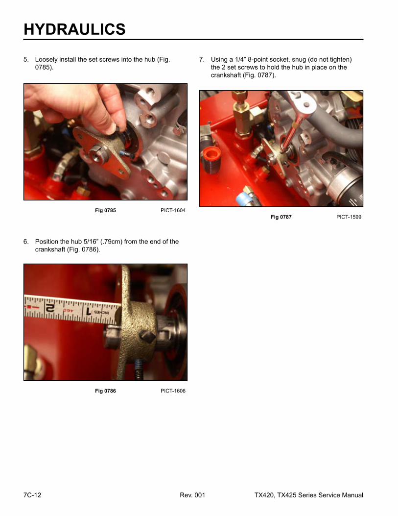
Fig 0786 PICT-1606
6. Position the hub 5/16” (.79cm) from the end of the crankshaft (Fig. 0786).
Fig 0785 PICT-1604
5. Loosely install the set screws into the hub (Fig. 0785).
Fig 0787 PICT-1599
7. Using a 1/4” 8-point socket, snug (do not tighten) the 2 set screws to hold the hub in place on the crankshaft (Fig. 0787).

HYDRAULICS
7C-13TX420, TX425 Series Service Manual Rev. 001
Fig 0790 PICT-1597
8. Ensure the rubber coupler is assembled as follows (Fig. 0788):
a. Place the spacers over the cap screws with the spacer flange on the bolt head side.
b. Install 2 of the bolt assemblies into opposite holes on the rubber coupler.
c. Place a washer on each of the installed bolt assemblies.
d. Install the other 2 bolt assemblies into the rubber coupler in the opposite direction as the previous 2 bolt assemblies.
10. Position the pump mount onto the engine (Fig. 0790 and Fig. 0791).
Note: The 2 bolt holes on the pump mount that are closer together are installed on the top.
Fig 0789 PICT-3375a
9. Slide 2 of the rubber coupler bolts into the holes in the engine hub. Install a nut onto each of the bolts securing the coupler assembly to the engine hub (Fig. 0789).
Fig 0788 coupler asm1
A. Spacer Coupling (4) D. Engine HubB. Capscrews (4) E. Rubber Coupling (2)C. Nuts (2) F. Washers (4)
AB
C
DE
F

HYDRAULICS
7C-14 Rev. 001 TX420, TX425 Series Service Manual
Fig 0792 PICT-1611a
Fig 0794 PICT-1612
11. Install the two bolts and washers into the lower holes of the pump mount to secure the pump mount to the engine (Fig. 0792).
13. Install 2 lower bolts and washers and one upper bolt securing the heat shield in place (Fig. 0794).
Fig 0793 PICT-1595
Fig 0791 PICT-1609a
12. Position the muffler heat shield onto the engine above the muffler (Fig. 0793).

HYDRAULICS
7C-15TX420, TX425 Series Service Manual Rev. 001
Fig 0796 PICT-1594
Fig 0798 PICT-1619
15. Using an 8mm socket, tighten the upper bolt securing the heat shield to the throttle plate linkage (Fig. 0796).
c. Loader arm and drived. Auxiliary line
Fig 0797 PICT-1618
Fig 0795 PICT-1614
1. Top view of the hydraulic tandem pump (Fig. 0797 and Fig. 0798):a. Suction hose fittingb. Suction hose fitting
14. Using a 5/8” socket, torque the 4 bolts securing the pump mount onto the engine to 50 ft-lbs. (67.79 Nm) (Fig. 0795).
A B
C D
Hydraulic Tandem Pump Installation

HYDRAULICS
7C-16 Rev. 001 TX420, TX425 Series Service Manual
Fig 0800 PICT-1620a
Fig 0802 PICT-1621a
3. Using 1/4”, 8-point socket, remove the 2 set screws securing the hub to the hydraulic tandem pump shaft. Remove the hub (Fig. 0800).
4. Install the replacement key into hydraulic pump shaft keyway (Fig. 0802).
Fig 0801 PICT-1621a Fig 0799 PICT-1627a
3. Remove the key from the hydraulic pump shaft key-way (Fig. 0801).
2. Measure the distance from the face of the hydraulic tandem pump to the face of the hub and note the measurement (Fig. 0799).

HYDRAULICS
7C-17TX420, TX425 Series Service Manual Rev. 001
Fig 0804 PICT-1624a Fig 0806 PICT-1626a
6. Apply thread locking compound to the 2 hub set screws (Fig. 0804).
8. Slide the hub assembly onto the hydraulic pump shaft (Fig. 0806).
Fig 0805 PICT-1625a Fig 0803 PICT-1623a
7. Loosely install the 2 set screws into the hub (Fig. 0805).
5. Apply anti-seize compound to the hydraulic pump shaft (Fig. 0803).

HYDRAULICS
7C-18 Rev. 001 TX420, TX425 Series Service Manual
Fig 0808 PICT-1628a
Fig 0810 PICT-1631a
10. Finger tighten the 2 set screws to secure the hub in position (Fig. 0808).
13. Using a 9/16” wrench, tighten the two bolts equally to draw the hydraulic pump up to the pump mount (Fig. 0810).
Fig 0809 PICT-1630a
Fig 0807 PICT-1627a
11. Position the pump assembly by inserting the pump hub into the pump mount. Align the pump hub to the 2 bolt/spacer/washer assemblies on the rubber coupler.
12. Install the 2 bolts that secure the hydraulic pump to the pump mount (Fig. 0809).
9. Position the hub assembly onto the pump shaft in the same location as before the hub was removed (see the previously noted measurement) (Fig. 0807).

HYDRAULICS
7C-19TX420, TX425 Series Service Manual Rev. 001
Fig 0812 PICT-1632
Fig 0814 PICT-1581a
16. Tighten and torque all 4 set screws (2 on each hub) to 90 – 110 in-lbs. (10.17 – 12.43 Nm) (Fig. 0812).
Note: Reinstall both spark plug wires.
18. Using a 15/16” wrench, connect the hydraulic line (loader arm and hydrostatic pumps) to the hydraulic fitting located on the left side of the hydraulic pump (Fig. 0814).
Fig 0813 PICT-1585a
Fig 0811 PICT-1629a
17. Using a 1-1/8” wrench, connect the hydraulic line (auxiliary) to the hydraulic fitting located on the left side of the hydraulic pump (Fig. 0813).
14. Install a nut onto one of the rubber coupler bolt assemblies. Tighten the nut using 1/2” wrenches.
15. Rotate the crank/pump shaft 180º. Install a nut onto the other rubber coupler bolt assembly. Tighten using 1/2” wrenches (Fig. 0811).

HYDRAULICS
7C-20 Rev. 001 TX420, TX425 Series Service Manual
Fig 0816 PICT-1533
20. Slide the 2 hose clamps into place. Using a 5/16” socket, tighten the two hose clamps onto the hydraulic pump suction hoses to secure them to the fittings on the tandem pump (Fig. 0816).
Fig 0815 PICT-1534
19. Connect the two suction hoses to the fittings on the right side of the hydraulic tandem pump (Fig. 0815).
Hydraulic Tandem Pump Rebuild
TX420 & 425 240000301 & up
Fig 0817 PICT-2823
Note: Cleanliness is a key factor in a successful repair of any hydraulic system. Thoroughly clean all exposed surfaces prior to any type of maintenance. Cleaning all parts by using a solvent wash and air drying is usually adequate. As with any precision equipment, all parts must be kept free of foreign material and chemicals. Protect all exposed sealing areas and open cavities from damage and foreign material.
Upon removal, all seals, o-rings, and gaskets should be replaced. During installation, lightly lubricate all seals, o-rings, and gaskets with clean oil prior to assembly.
1. Remove the key from the keyway of the pump shaft Fig. 0817).

HYDRAULICS
7C-21TX420, TX425 Series Service Manual Rev. 001
Fig 0819 PICT-2825a
Fig 0821 PICT-2828
4. Using a 7mm Allen wrench, loosen and remove the 4 bolts and washers securing the pump sections (Fig. 0819).
6. Remove the cap gasket from the pump housing (Fig. 0821).
Fig 0820 PICT-2826a
Fig 0818 PICT-2824a
5. Remove the cover from the pump assembly (Fig. 0820).
2. Secure the pump in a vise.
3. Mark the casing of the pump with a “V” that crosses over all sections of the pump (Fig. 0818).

HYDRAULICS
7C-22 Rev. 001 TX420, TX425 Series Service Manual
Fig 0823 PICT-2830a
Fig 0825 PICT-2833
2. Using a needle nose pliers, grab the center of the small bushing and lift the bushing from the pump housing assembly (Fig. 0823).
4. Remove the drive gear from the pump assembly (Fig. 0825).
Fig 0824 PICT-2832a
Fig 0822 PICT-2829
3. Remove the driven gear from the pump assembly (Fig. 0824).
1. Mark the bushing assembly with a single line that extends out onto the pump housing (Fig. 0822).
5 gpm Pump Disassembly

HYDRAULICS
7C-23TX420, TX425 Series Service Manual Rev. 001
Fig 0827 PICT-2835 Fig 0829 PICT-2838
6. Mark the inner small bushing assembly with a line that extends out onto the pump housing. This line should be on the opposite side as the previous marking (Fig. 0827).
1. Lift the pump housing off the 11 gpm pump housing (Fig. 0829).
Fig 0828 PICT-2836 Fig 0826 PICT-2834a
7. Lift the inner small bushing out of the pump housing (Fig. 0828).
5. Using a needle nose pliers grab the center of the inner small bushing and lift it partially out of the pump housing (Fig. 0826).
11 gpm Pump Disassembly

HYDRAULICS
7C-24 Rev. 001 TX420, TX425 Series Service Manual
Fig 0831 PICT-2839a Fig 0833 PICT-2841
3. Remove the drive link from the drive gear (Fig. 0831). 5. Remove the large pump bushing assembly from the
pump shaft cover (Fig. 0833).
Fig 0832 PICT-2840 Fig 0830 PICT-2882a
4. Mark the large pump bushing assembly with a “V” all the way down onto the pump shaft cover (Fig. 0832).
2. Remove the o-ring from the housing (Fig. 0830).

HYDRAULICS
7C-25TX420, TX425 Series Service Manual Rev. 001
Fig 0835 PICT-2843 Fig 0837 PICT-2846a
7. With the cover secured so the inside of the cover is facing up, remove the shaft seal from the inside of the pump cover (Fig. 0835).
9. Carefully drive the seal into the cover until it is seated (Fig. 0837).
Fig 0836 PICT-2844a Fig 0834 PICT-2842a
8. Install a new shaft seal in the pump cover so that the spring side of the seal is facing the housing side of the pump cover (Fig. 0836).
6. Using a snap ring pliers, remove the snap ring from the pump cover (Fig. 0834).

HYDRAULICS
7C-26 Rev. 001 TX420, TX425 Series Service Manual
Fig 0839 PICT-2849a
Fig 0841 PICT-2851a
Note: Lubricate all surfaces on reassembly.
1. Remove the bushing from the drive gear and driven gear shafts (Fig. 0839).
3. Remove the drive gear from the bushing (Fig. 0841).
Fig 0840 PICT-2850a Fig 0838 PICT-2848
2. Remove the driven gear from the bushing (Fig. 0840).
10. Install the snap ring into the pump cover (Fig. 0838).
11 gpm Pump Assembly Rebuild

HYDRAULICS
7C-27TX420, TX425 Series Service Manual Rev. 001
Fig 0843 PICT-2854a Fig 0845 PICT-2856a
5. Inspect the drive gear and driven gear surfaces for damage (Fig. 0843).
7. Remove the gear seal from the top and bottom bushings (Fig. 0845).
Fig 0844 PICT-2855a Fig 0842 PICT-2853a
6. Remove the back-up ring from the top and bottom bushings (Fig. 0844).
4. Inspect the gear surface of both of the bushings for damage (Fig. 0842).

HYDRAULICS
7C-28 Rev. 001 TX420, TX425 Series Service Manual
Fig 0849 PICT-2864a
12. Install the driven gear into the bushing (Fig. 0849).
Fig 0848 PICT-2863a
Fig 0846 PICT-2861
10. Repeat the previous 2 steps for the second bushing, gear seal and back-up ring.
11. Making note of the markings on the bushing assembly, install the drive gear into the bushing (Fig. 0848).
8. Install the gear seal with the lip side of the gasket facing away from the groove of the bushing (Fig. 0846).
Fig 0847 PICT-2862
9. Install the back-up ring into the bushing so that it rests in the lip of the gear seal (Fig. 0847).

HYDRAULICS
7C-29TX420, TX425 Series Service Manual Rev. 001
Fig 0851 PICT-2866a
Fig 0853 PICT-2868a
Note: Lubricate all surfaces on reassembly.
1. Remove one of the bushings (Fig. 0851).
3. Remove the drive gear (Fig. 0853).
Fig 0852 PICT-2867a
Fig 0850 PICT-2865a
2. Remove the driven gear (Fig. 0852).13. Install the second bushing onto the 2 gears (Fig. 0850).
5 gpm Pump Assembly Rebuild

HYDRAULICS
7C-30 Rev. 001 TX420, TX425 Series Service Manual
Fig 0855 PICT-2876a Fig 0857 PICT-2875a
5. Inspect the drive and driven gears for damage (Fig. 0855).
7. Remove the gear seal from the both of the bushings (Fig. 0857).
Fig 0856 PICT-2874a Fig 0854 PICT-2870a
6. Remove the back-up ring from both of the bushings (Fig. 0856).
4. Inspect the gear surfaces of both the bushings for damage (Fig. 0854).

HYDRAULICS
7C-31TX420, TX425 Series Service Manual Rev. 001
Fig 0859 PICT-2878a
Fig 0861 PICT-2880a
9. Install the back-up ring into the bushing so that it rests in the lip of the gear seal (Fig. 0859).
12. Install the driven gear onto the bushing (Fig. 0861).
Fig 0860 PICT-2879a
Fig 0858 PICT-2877a
10. Repeat the above 2 steps for the second bushing, gear seal and back-up ring.
11. Making note of the markings on the bushing assembly, install the drive gear into the bushing (Fig. 0860).
8. Install the gear seal with the lip side of the gasket facing away from the groove of the bushing (Fig. 0858).

HYDRAULICS
7C-32 Rev. 001 TX420, TX425 Series Service Manual
Fig 0863 PICT-2884a
Fig 0865 PICT-2886a
14. Inspect the drive link for damage (Fig. 0863).
2. Install the drive link onto the drive gear of the 11 gpm pump assembly (Fig. 0865).
Fig 0864 PICT-2885a
Fig 0862 PICT-2881a
1. Making note of the marks on the 11 gpm pump, slide the drive gear shaft of the 11 gpm pump assembly onto the mounting flange (Fig. 0864).
13. Install the second bushing onto the 2 gears (Fig. 0862).
Pump Assembly

HYDRAULICS
7C-33TX420, TX425 Series Service Manual Rev. 001
Fig 0869 PICT-2894a
6. Install the cover o-ring into the housing (Fig. 0869).
Fig 0866 PICT-2882a
Fig 0868 PICT-2892a
3. Install the mounting flange o-ring into the housing groove (Fig. 0866).
5. Making note of the markings on the 5 gpm pump assembly, slide the 5 gpm pump assembly into the housing (Fig. 0868).
Note: The pump shaft may have to be rotated to seat the 5 gpm pump onto the drive link.
Fig 0867 PICT-2890a
4. Making note of the markings on the housing and mounting flange, install the pump housing over the 11 gpm pump assembly and onto the mounting flange (Fig. 0867).

HYDRAULICS
7C-34 Rev. 001 TX420, TX425 Series Service Manual
Fig 0870 PICT-2895a
7. Install the housing cover onto the housing (Fig. 0870).
Fig 0872 PICT-2898a
9. Install the key into the keyway on the pump shaft (Fig. 0872).
Fig 0871 PICT-2896a
8. Using a 7mm Allen wrench, install the 4 bolts that secure the housing cover to the housing (Fig. 0871). Torque to 19 - 23 ft-lbs. (25.8 - 31.2 Nm).
1. Remove attachment from the traction unit.
2. Park the machine on a level surface.
3. Extend the tilt cylinder so that the attach plate lays parallel to the floor.
Tilt Cylinder Replacement
TX420 & 425 250000401 & up

HYDRAULICS
7C-35TX420, TX425 Series Service Manual Rev. 001
Fig 0876 PICT-1802
11. Using a 1/2” socket, remove the bolt securing the pivot pin to the quick attach assembly on the ram end of the tilt cylinder (Fig. 0876).
Fig 0875 PICT-1801
10. Using a 13/16” wrench, loosen and remove the two hydraulic lines from the tilt cylinder fittings (Fig. 0875).
Note: Capallhydrauliclinesandfittingssothatdebris does not enter the system.
Fig 0874 PICT-1800
5. Shut engine off.
6. Stroke the loader valve from dump to curl to remove pressure from the hydraulic lines.
7. Let hydraulic oil cool.
8. Place a drain pan under the tilt cylinder fittings.
9. Mark 1 of the 2 hydraulic tilt cylinder lines and fittings with the letter “A” (Fig. 0874).
Fig 0873 PICT-1799
4. Rest the quick attach assembly on wood blocks (Fig. 0873).

HYDRAULICS
7C-36 Rev. 001 TX420, TX425 Series Service Manual
Fig 0878 PICT-1805
13. Using a 1/2” socket and wrench, remove the bolt and nut securing the pivot pin to the loader arm (Fig. 0878).
Fig 0877 PICT-1804
12. Remove the pivot pin that secures the tilt cylinder to the quick attach assembly (Fig. 0877).
Fig 0880 PICT-1807
15. Using a 5/16” wrench, remove the grease fitting from the barrel end of the tilt cylinder (Fig. 0880).
Fig 0879 PICT-1806
14. Using a hammer and a punch, remove the pivot pin from the loader arm and cylinder barrel (Fig. 0879).

HYDRAULICS
7C-37TX420, TX425 Series Service Manual Rev. 001
Fig 0882 PICT-1808
1. Replace o-rings on the hydraulic cylinder fittings.
2. Using a 3/4” wrench, install two hydraulic fittings into the two ports of the tilt cylinder barrel (Fig. 0882).
Fig 0881 PICT-1808
16. Using a 3/4” wrench, remove the two hydraulic fittings from the tilt cylinder barrel (Fig. 0881).
Tilt Cylinder Installation
Fig 0883 PICT-1807
3. Using a 5/16” wrench, install the grease fitting into the barrel end of the tilt cylinder (Fig. 0883).
Fig 0884 PICT-1804
4. Place the tilt cylinder into the loader arm with the hydraulic fittings facing toward the rear and the grease fitting on the barrel end facing up. Install the lower pivot pin to secure the cylinder ram to the quick attach assembly (Fig. 0884).
HYDRAULICS
7C-38 Rev. 001 TX420, TX425 Series Service Manual
Fig 0885 PICT-1810 Fig 0887 PICT-1805
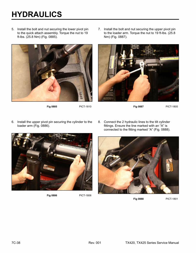
5. Install the bolt and nut securing the lower pivot pin to the quick attach assembly. Torque the nut to 19 ft-lbs. (25.8 Nm) (Fig. 0885).
7. Install the bolt and nut securing the upper pivot pin to the loader arm. Torque the nut to 19 ft-lbs. (25.8 Nm) (Fig. 0887).
Fig 0886 PICT-1806
6. Install the upper pivot pin securing the cylinder to the loader arm (Fig. 0886).
Fig 0888 PICT-1801
8. Connect the 2 hydraulic lines to the tilt cylinder fittings. Ensure the line marked with an “A” is connected to the fitting marked “A” (Fig. 0888).

HYDRAULICS
7C-39TX420, TX425 Series Service Manual Rev. 001
9. Start the machine and check for leaks.
10. Remove air from the system. Refer to “Purging Air Procedures” on page 12-27.
11. Remove the wood blocks and lower the loader arms.
Tilt Cylinder Assembly Rebuild
TX420 & 425 230000601 & up
Fig 0889 PICT-2954
1. Extend the ram of the tilt cylinder out approximately 6 to 12 inches (15.24 to 30.48cm).
2. Clean away all dirt and foreign substance from openings, particularly at the head of the hydraulic cylinder.
3. Clamp the tilt cylinder in a vise so that the locking ring slot is facing up.
4. Clean out all material from the locking slot (Fig. 0889).
Fig 0890 PICT-2953
Note: If excessive wear due to side-loads or binding is a possibility, mark or note the piston and head relationship to the rod and tube. This condition will usually show up as a highly polished surface on the piston and head 90° to the pin rotation axis (Fig. 0890).
Fig 0891 PICT-2956
5. Using a spanner wrench installed in the holes provided, rotate the head clockwise until the beveled edge of the retaining ring appears in the milled opening of the tube. Insert a flat blade screwdriver between the beveled edge of the retaining ring and the cylinder barrel to start the retaining ring through the opening (Fig. 0891).

HYDRAULICS
7C-40 Rev. 001 TX420, TX425 Series Service Manual
Fig 0893 PICT-2958a
7. Pull out on the rod to remove the piston and head assembly from the barrel (Fig. 0893).
Fig 0892 PICT-2957
8. Remove the barrel from the vise.
INSPECT ROD: There should be no scratches or pits deep enough to catch the fingernail. Pits that go to the base metal are unacceptable. Scratches that catch the fingernail but are not to the base metal, less than 0.5 inch long (1.27cm) and primarily in the circumferential direction are acceptable provided they cannot cut the rod seal. Chrome should be present over the entire surface of the rod and the lack thereof is unacceptable. In the event that an unacceptable condition occurs, the cylinder should be replaced.
INSPECT HEAD: Visually inspect the inside bore for scratches or polishing. Deep scratches are unacceptable. Polishing indicates uneven loading and when this occurs, the bore should be checked for out of-roundness. If out-of-roundness exceeds 0.007” (.18mm), this is unacceptable. Check the condition of the dynamic seals, looking particularly for metallic particles embedded in the piston seal surface. Remove the seals. Damage to the seal grooves, particularly on the sealing surfaces, is unacceptable. In the event that an unacceptable condition occurs, the cylinder should be replaced.
6. Continue to rotate the head counter-clockwise until the retaining ring is completely removed (Fig. 0892).
HYDRAULICS
7C-41TX420, TX425 Series Service Manual Rev. 001
Fig 0896 PICT-2962
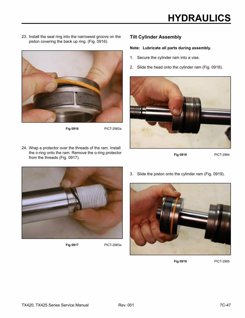
2. Carefully remove the seal from the ram assembly (Fig. 0896).
Fig 0895 PICT-2961
Fig 0894 PICT-2959a
1. Remove the piston wear ring from the ram assembly (Fig. 0895).
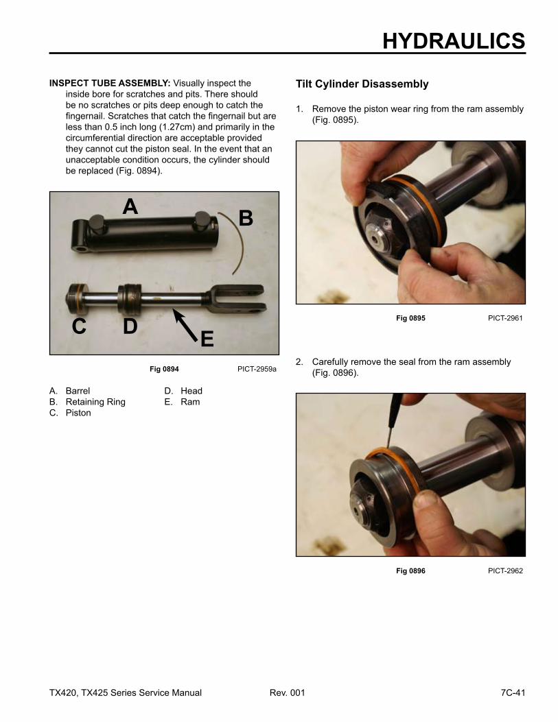
INSPECT TUBE ASSEMBLY: Visually inspect the inside bore for scratches and pits. There should be no scratches or pits deep enough to catch the fingernail. Scratches that catch the fingernail but are less than 0.5 inch long (1.27cm) and primarily in the circumferential direction are acceptable provided they cannot cut the piston seal. In the event that an unacceptable condition occurs, the cylinder should be replaced (Fig. 0894).
Tilt Cylinder Disassembly
A. Barrel D. HeadB. Retaining Ring E. RamC. Piston
A B
C D E

HYDRAULICS
7C-42 Rev. 001 TX420, TX425 Series Service Manual
Fig 0898 PICT-2964
Fig 0900 PICT-2966
4. Using a 1-1/2” socket, remove the nut from the ram assembly (Fig. 0898).
6. Remove the o-ring from the ram (Fig. 0900).
Fig 0899 PICT-2965 Fig 0897 PICT-2963
5. Slide the piston off the end of the ram (Fig. 0899).3. Remove the back-up piston seal from the ram assembly (Fig. 0897).

HYDRAULICS
7C-43TX420, TX425 Series Service Manual Rev. 001
Fig 0902 PICT-2968 Fig 0904 PICT-2970
8. Remove the flat back-up ring from the head on the ram assembly (Fig. 0902).
10. Remove the wiper seal from inside the head (Fig. 0904).
Fig 0903 PICT-2969 Fig 0901 PICT-2967
9. Slide the head off the end of the ram (Fig. 0903).7. Remove the o-ring from the head on the ram assembly (Fig. 0901).

HYDRAULICS
7C-44 Rev. 001 TX420, TX425 Series Service Manual
Fig 0906 PICT-2972a
12. Turn the head over and remove the wear ring from inside of head. (Fig. 0906).
Fig 0907 PICT-2973a
Fig 0905 PICT-2971
13. Thoroughly rinse the inside of the tube with a clean solvent. Rinse and clean all internal components of foreign material with a lint-free rag.
14. Visually inspect for material defects and contami-nation. All seals and o-rings must be replaced with new parts.
Head Assembly (Fig. 0907):
11. Remove the seal from inside the head (Fig. 0905).
A. Wiper Seal D. HeadB. Seal E. Backup RingC. Wear Ring F. O-Ring Seal
A B C D E F

HYDRAULICS
7C-45TX420, TX425 Series Service Manual Rev. 001
Fig 0908 PICT-2974
A. Piston Seal D. Wear Ring B. Back-up Piston Seal E. LocknutC. Piston
A B C D E
Piston Assembly (Fig. 0908):
Fig 0910 PICT-2976
17. Turn the head over and twist the wear seal into a “C” shape and allow it to snap into the groove (Fig. 0910).
Note: The groove of the seal faces toward the barrel side of the head.
Fig 0909 PICT-2975a
15. Lubricate the head and all seals with 10W-30 oil prior to installation.
16. From the bottom of the head install the wear ring (Fig. 0909).
Fig 0911 PICT-2977
18. Install the wiper seal so that the lip of the seal is installed in the groove inside the head (Fig. 0911).

HYDRAULICS
7C-46 Rev. 001 TX420, TX425 Series Service Manual
Fig 0914 PICT-2980a
21. Install the wear ring into the widest groove on the piston (Fig. 0914).
Fig 0915 PICT-2981a
Fig 0913 PICT-2979
22. Install the backup ring into the narrowest groove on the piston (Fig. 0915).20. Install the o-ring into the deepest groove in the
head. The o-ring is installed on the barrel side of the groove (Fig. 0913).
Note: If possible, the head/seal assembly should sit for at least one hour to allow the seals to normalize.
Fig 0912 PICT-2978a
19. Install the flat back-up ring into the deepest groove in the head. The flat back-up seal is installed up against the ram side of the groove (Fig. 0912).
HYDRAULICS
7C-47TX420, TX425 Series Service Manual Rev. 001
Fig 0916 PICT-2982a
23. Install the seal ring into the narrowest groove on the piston covering the back up ring. (Fig. 0916).
Fig 0918 PICT-2984
Note: Lubricate all parts during assembly.
1. Secure the cylinder ram into a vise.
2. Slide the head onto the cylinder ram (Fig. 0918).
Fig 0919 PICT-2985
Fig 0917 PICT-2983a
3. Slide the piston onto the cylinder ram (Fig. 0919).
24. Wrap a protector over the threads of the ram. Install the o-ring onto the ram. Remove the o-ring protector from the threads (Fig. 0917).
Tilt Cylinder Assembly

HYDRAULICS
7C-48 Rev. 001 TX420, TX425 Series Service Manual
Fig 0922 PICT-2988
7. Rotate the head until the ring hole in the ring groove is within the slot on the barrel (Fig. 0922).
Fig 0923 PICT-2991
Fig 0921 PICT-2987a
8. Insert the bent end of the ring through the notch in the barrel and into the hole in the groove. Place the spanner wrench onto the head assembly (Fig. 0923).
5. Remove the ram from the vise and secure the cylinder barrel into the vise.
6. Install the ram assembly into the cylinder barrel by rotating the head assembly while pushing the head into the barrel (Fig. 0921).
Fig 0920 PICT-2986
4. Install the nut onto the end of the ram. Using a 1-1/2” socket, torque the nut to 110 - 120 ft-lbs. (149.1 - 162.7 Nm) (Fig. 0920).

HYDRAULICS
7C-49TX420, TX425 Series Service Manual Rev. 001
Fig 0924 PICT-2994
9. Begin rotating the spanner wrench so that the head pulls the ring inside the barrel. Continue rotating until the beveled edge of ring is completely installed inside the barrel on the head assembly (Fig. 0924).
Note: The following procedure applies to both left and right side lift cylinders.
1. Remove attachment from the traction unit.
2. Park the machine on a level surface.
3. Raise the loader arms approximately 5” (12.7cm) from the frame straps.
TX425 250000401 & up
Lift Cylinder Replacement
Fig 0925 PICT-1781
4. Place two jack stands under the attach plate assembly. Lower the loader arms onto the jack stands to support the loader arms (Fig. 0925).
Fig 0926 PICT-1783
5. Shut engine off.
6. Stroke loader valve from raise to lower position to remove pressure from the hydraulic lines.
7. Let the hydraulic oil cool.
8. Using a 1/2” socket and wrench, remove the bolt and nut securing the lift cylinder pivot pin to the tower (Fig. 0926).

HYDRAULICS
7C-50 Rev. 001 TX420, TX425 Series Service Manual
Fig 0930 PICT-1786
13. Mark one of the hydraulic lines and corresponding fitting with the letter “A” (Fig. 0930).
Fig 0929 PICT-1785
12. Turn the lift cylinder so that the hydraulic fitting connections are facing the outside of the machine (Fig. 0929).
Fig 0928 PICT-1784
11. Support the lift cylinder and remove the pivot pin from the tower assembly (Fig. 0928).
Fig 0927 DSC-3576
9. Open the hood to the full upright position and support it with the hood support rod.
10. To get the pivot pin removal started, use a round steel rod approximately 30” (76.2cm) long and a hammer. Insert the rod between the engine plate and pump belt from the opposite side of the lift cylinder being removed. Using the hammer, tap on the rod, striking the pin from inside of the tower assembly, pushing the pin to the outside of the tower assembly (Fig. 0927).

HYDRAULICS
7C-51TX420, TX425 Series Service Manual Rev. 001
Fig 0932 PICT-1788
15. Using a 13/16” wrench, disconnect the second hydraulic line from the cylinder fitting (Fig. 0932).
Note: Capallhydrauliclinesandfittingssothatdebris does not enter the system.
Fig 0931 PICT-1787
14. Using a 13/16” wrench, disconnect the hydraulic line marked “A” from the cylinder fitting (Fig. 0931).
Fig 0934 PICT-1790
17. Using a punch and hammer, tap the front pivot pin partially out (Fig. 0934).
Fig 0933 PICT-1789
16. Using a 1/2” socket and wrench, remove the bolt and nut from the pivot pin securing the front of the cylinder to the loader arm (Fig. 0933).

HYDRAULICS
7C-52 Rev. 001 TX420, TX425 Series Service Manual
Fig 0938 PICT-1794a
21. Using a 5/16” wrench, remove the straight grease fitting from the ram end of the cylinder and install it into the replacement cylinder (Fig. 0938).
Fig 0937 PICT-1793
20. Using a 3/8” wrench, remove the 45º grease fitting from the barrel end of the cylinder and install it into the replacement cylinder (Fig. 0937).
Fig 0936 PICT-1792a
19. Remove the lift cylinder from the frame (Fig. 0936).
Fig 0935 PICT-1791
18. Support the lift cylinder and remove the front pivot pin (Fig. 0935).

HYDRAULICS
7C-53TX420, TX425 Series Service Manual Rev. 001
Fig 0940 PICT-1792a
23. Replace the o-rings on the hydraulic cylinder fittings.
24. Place the lift cylinder into the frame with the hydraulic fittings facing out (Fig. 0940).
Fig 0939 PICT-1795a
22. Using a 3/4” wrench, remove both fittings from the cylinder and install them into the replacement cylinder (Fig. 0939).
Fig 0942 PICT-1796
27. Install the bolt and nut securing the front pivot pin to the loader arms. Torque the nut to 19 ft-lbs. (25.76 Nm) (Fig. 0942).
Fig 0941 PICT-1791
25. Ensure the grease fitting on the ram end of the cylinder is facing down.
26. Install the front pivot pin securing the cylinder ram to the loader arm (Fig. 0941).

HYDRAULICS
7C-54 Rev. 001 TX420, TX425 Series Service Manual
Fig 0946 PICT-1797
32. Install the bolt and nut securing the rear pivot pin to the tower assembly. Torque the nut to 19 ft-lbs. (25.76 Nm) (Fig. 0946).
Fig 0945 PICT-1784a
30. Ensure the grease fitting on the cylinder end is facing up.
31. Install the rear pivot pin securing the cylinder to the tower assembly (Fig. 0945).
Fig 0944 PICT-1785
29. Turn the cylinder so that the hydraulic connections are facing down (Fig. 0944).
Fig 0943 PICT-1786
28. Connect the 2 hydraulic lines to the lift cylinder fittings. Ensure the line marked with an “A” is connected to the fitting marked “A” (Fig. 0943).

HYDRAULICS
7C-55TX420, TX425 Series Service Manual Rev. 001
33. Start the machine and check for leaks.
34. Remove air from the system. Refer to “Purging Air Procedures” on page 12-27.
35. Lower the loader arms.
Fig 0949 PICT-3036
5. Using a spanner wrench installed in the holes provided, rotate the head counterclockwise until the edge of the retaining ring appears in the milled opening of the tube. Insert a flat blade screwdriver between the beveled edge of the retaining ring and the cylinder barrel to start the retaining ring through the opening (Fig. 0949).
Fig 0948 PICT-3035
Note: If excessive wear due to side-loads or binding is a possibility, mark or note the piston and head relationship to the rod and tube. This condition will usually show up as a highly polished surface on the piston and head 90° to the pin rotation axis (Fig. 0948).
Lift Cylinder Assembly Rebuild
TX420 & 425 240000001 & up
Fig 0947 PICT-3034
1. Extend the ram of the tilt cylinder out approximately 6” to 12” (15.24 to 30.48cm).
2. Clean all dirt and other foreign substance from the openings, particularly at the head of the hydraulic cylinder.
3. Clamp the tilt cylinder in a vise so that the locking ring slot is facing up.
4. Clean out all material from the locking slot (Fig. 0947).
HYDRAULICS
7C-56 Rev. 001 TX420, TX425 Series Service Manual
Fig 0951 PICT-3038a
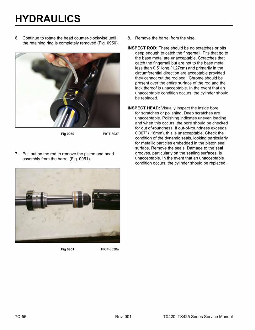
7. Pull out on the rod to remove the piston and head assembly from the barrel (Fig. 0951).
Fig 0950 PICT-3037
6. Continue to rotate the head counter-clockwise until the retaining ring is completely removed (Fig. 0950).
8. Remove the barrel from the vise.
INSPECT ROD: There should be no scratches or pits deep enough to catch the fingernail. Pits that go to the base metal are unacceptable. Scratches that catch the fingernail but are not to the base metal, less than 0.5” long (1.27cm) and primarily in the circumferential direction are acceptable provided they cannot cut the rod seal. Chrome should be present over the entire surface of the rod and the lack thereof is unacceptable. In the event that an unacceptable condition occurs, the cylinder should be replaced.
INSPECT HEAD: Visually inspect the inside bore for scratches or polishing. Deep scratches are unacceptable. Polishing indicates uneven loading and when this occurs, the bore should be checked for out of-roundness. If out-of-roundness exceeds 0.007” (.18mm), this is unacceptable. Check the condition of the dynamic seals, looking particularly for metallic particles embedded in the piston seal surface. Remove the seals. Damage to the seal grooves, particularly on the sealing surfaces, is unacceptable. In the event that an unacceptable condition occurs, the cylinder should be replaced.

HYDRAULICS
7C-57TX420, TX425 Series Service Manual Rev. 001
Fig 0954 PICT-3041a
2. Remove the piston seal from the ram assembly (Fig. 0954).
Fig 0953 PICT-3040
1. Remove the wear ring from the piston (Fig. 0953).
Lift Cylinder Disassembly
Fig 0952 PICT-3039a
INSPECT TUBE ASSEMBLY: Visually inspect the inside bore for scratches and pits. There should be no scratches or pits deep enough to catch the fingernail. Scratches that catch the fingernail but are less than 0.5” long (1.27cm) and primarily in the circumferential direction are acceptable provided they cannot cut the piston seal. In the event that an unacceptable condition occurs, the cylinder should be replaced (Fig. 0952).
A. Barrel D. HeadB. Retaining Ring E. RamC. Piston
A B
C D E

HYDRAULICS
7C-58 Rev. 001 TX420, TX425 Series Service Manual
Fig 0956 PICT-3043a
4. Using a 1-1/8” socket, remove the nut from the ram assembly (Fig. 0956).
Fig 0955 PICT-3042a
3. Remove the back-up piston seal from the ram assembly (Fig. 0955).
Fig 0958 PICT-3046a
6. Remove the inner o-ring from the inside of the piston (Fig. 0958).
Fig 0957 PICT-3045a
5. Slide the piston off the end of the ram (Fig. 0957).

HYDRAULICS
7C-59TX420, TX425 Series Service Manual Rev. 001
Fig 0962 PICT-3050a
10. Remove the wiper seal from inside the head (Fig. 0962).
Fig 0961 PICT-3049a
9. Slide the head off the end of the ram (Fig. 0961).
Fig 0960 PICT-3048a
8. Remove the flat back-up ring from the head on the ram assembly (Fig. 0960).
Fig 0959 PICT-3047a
7. Remove the o-ring from the head on the ram assembly (Fig. 0959).

HYDRAULICS
7C-60 Rev. 001 TX420, TX425 Series Service Manual
Fig 0964 PICT-3052a
12. Thoroughly rinse the inside of the head with a clean solvent. Rinse and clean all internal components of any foreign material with a lint-free rag.
13. Visually inspect for material defects and contami-nation. All seals and o-rings must be replaced with new parts.
Head Assembly (Fig. 0964):
Fig 0963 PICT-3051
11. Remove the wear seal from inside the head (Fig. 0963).
A. Wiper D. Static Back-upB. Wear Seal E. Static O-RingC. Head
A B C D E
Fig 0966 PICT-3057
14. Lubricate the head and all seals with 10W-30 oil prior to installation. Twist the wear seal into a “C” shape and allow it to snap into the groove (Fig. 0966).
Note: The groove of the seal faces toward the barrel side of the head.
Fig 0965 PICT-3056a
A. Piston Inner O-ring D. PistonB. Backup Piston Seal E. Wear RingC. Piston Seal F. Locknut
A B C D E F
Piston Assembly (Fig. 0965):

HYDRAULICS
7C-61TX420, TX425 Series Service Manual Rev. 001
Fig 0970 PICT-3061a
18. Install the back-up ring into the piston (Fig. 0970).
Fig 0969 PICT-3060a
17. Install the o-ring into the groove next to the flat back-up ring. The o-ring is installed on the barrel side of the groove (Fig. 0969).
Note: If possible, the head/seal assembly should sit for at least one hour to allow the seals to normalize.
Fig 0968 PICT-3059a
16. Install the flat back-up ring into the head. The flat back-up seal is installed up against the ram side of the groove (Fig. 0968).
Fig 0967 PICT-3058
15. Install the wiper seal so that the lip of the seal is installed in the groove inside the head (Fig. 0967).

HYDRAULICS
7C-62 Rev. 001 TX420, TX425 Series Service Manual
Fig 0972 PICT-3063a
20. Install the wear ring onto the piston (Fig. 0972).
Fig 0971 PICT-3062a
19. Install the piston seal on top of the back-up ring (Fig. 0971).
Fig 0974 PICT-3065a
3. Remove the thread protection material.
4. Slide the head onto the cylinder ram (Fig. 0974).
Fig 0973 PICT-3064a
Note: Lubricate all parts during assembly.
1. Secure the cylinder ram into a vise.
2. Protect the threads of the ram and then slide the o-ring onto the ram shaft and into the groove (Fig. 0973).
Lift Cylinder Assembly

HYDRAULICS
7C-63TX420, TX425 Series Service Manual Rev. 001
Fig 0978 PICT-3070a
9. Rotate the head until the ring hole in the ring groove is within the slot on the barrel (Fig. 0978).
Fig 0977 PICT-3068a
7. Remove the ram from the vise and secure the cylinder barrel into the vise.
8. Install the ram assembly into the cylinder barrel by rotating the piston assembly while pushing the piston into the barrel (Fig. 0977).
Fig 0976 PICT-3067a
6. Install the nut onto the end of the ram. Using a 1-1/8” socket, torque the nut to 100 - 120 ft-lbs. (135.6 - 162.7 Nm) (Fig. 0976).
Fig 0975 PICT-3066a
5. Slide the piston onto the cylinder ram (Fig. 0975).

HYDRAULICS
7C-64 Rev. 001 TX420, TX425 Series Service Manual
Fig 0980 PICT-3073
11. Begin rotating the spanner wrench so that the head pulls the ring inside the barrel. Continue rotating until the ring is completely installed inside the barrel on the head assembly (Fig. 0980).
Fig 0979 PICT-3071
10. Insert the end of the ring through the notch in the barrel and into the hole in the groove. Place the spanner wrench onto the head assembly (Fig. 0979).
Fig 0982 PICT-1751
3. Using a 3/8” socket remove the 4 screws from top panel. Remove panel (Fig. 0982).
Fig 0981 PICT-1729a
1. Park on a level surface and set the park brake.
2. Remove the rear panel (Fig. 0981).
Auxiliary Valve Removal
TX420 & 425 240000301 & up

HYDRAULICS
7C-65TX420, TX425 Series Service Manual Rev. 001
Fig 0984 PICT-1755
5. Using a 7/16” socket and wrench remove the 2 bolts and nuts from stop plate. Remove stop plate (Fig. 0984).
Fig 0983 PICT-1753
4. Using a 3/8” socket remove the 3 screws from the left side panel. Remove the panel (Fig. 0983).
Fig 0986 PICT-1761
7. Using a 1-1/8” wrench, remove line A from the valve fitting. Cap the line and fitting (Fig. 0986).
Fig 0985 PICT-1760
6. Mark each hydraulic line (Fig. 0985).
A. Inlet line from gear pumpB. Output line to female couplerC. Output line to male couplerD. Return oil to hydraulic oil cooler

HYDRAULICS
7C-66 Rev. 001 TX420, TX425 Series Service Manual
Fig 0988 PICT-1763
9. Using a 15/16” wrench, remove line C from the valve fitting. Cap the line and fitting (Fig. 0988).
Fig 0987 PICT-1762
8. Using a 15/16” wrench, remove line B from the valve fitting. Cap the line and fitting (Fig. 0987).
Fig 0990 PICT-1765
11. Disconnect the safety switch from the wire harness (Fig. 0990).
Fig 0989 PICT-1764
10. Using a 1-1/8” wrench, remove line D from the valve fitting. Cap the line and fitting (Fig. 0989).

HYDRAULICS
7C-67TX420, TX425 Series Service Manual Rev. 001
Fig 0992 PICT-1769
13. Lift the valve out of the frame (Fig. 0992).
Fig 0991 PICT-1768
12. Using a 1/2” socket and wrench remove the 2 mounting bolts and nuts (Fig. 0991).
Fig 0994 PICT-1779a
1. Using two 7/16” wrenches remove top nut and washer on the handle (Fig. 0994).
Fig 0993 PICT-1770
14. Remove the hydraulic fittings from the valve and reuse in the replacement valve (Fig. 0993).
Note: Replaceallo-ringsonthefittingspriortoinstalling into the replacement valve.
Handle Removal

HYDRAULICS
7C-68 Rev. 001 TX420, TX425 Series Service Manual
Fig 0996 PICT-1775a
3. Rotate the spring and remove it from the spacer (Fig. 0996).
Fig 0995 PICT-1774a
2. Remove the handle from the spacer (Fig. 0995).
Fig 0998 PICT-1778
5. Use a 1/2” wrench remove the screw from the valve cap (Fig. 0998).
Fig 0997 PICT-1777a
4. Use a 7/16” wrench to remove the spacer from the valve cap screw (Fig. 0997).
HYDRAULICS
7C-69TX420, TX425 Series Service Manual Rev. 001
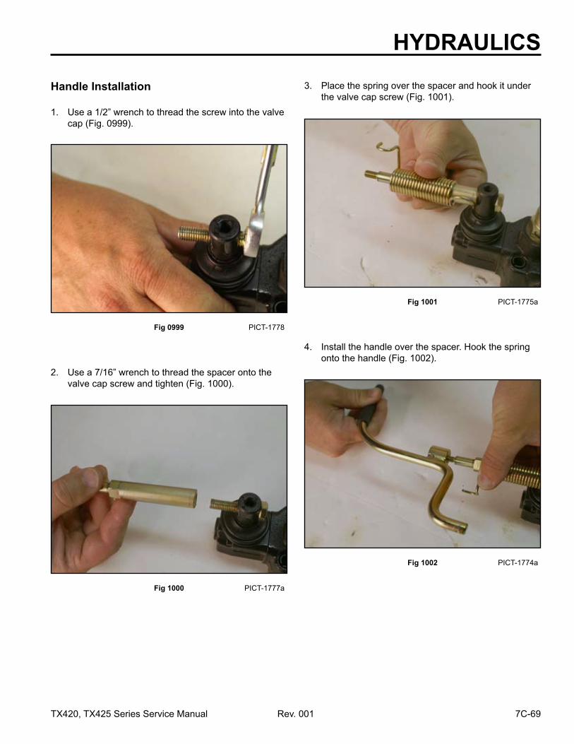
Fig 1000 PICT-1777a
2. Use a 7/16” wrench to thread the spacer onto the valve cap screw and tighten (Fig. 1000).
Fig 0999 PICT-1778
1. Use a 1/2” wrench to thread the screw into the valve cap (Fig. 0999).
Handle Installation
Fig 1002 PICT-1774a
4. Install the handle over the spacer. Hook the spring onto the handle (Fig. 1002).
Fig 1001 PICT-1775a
3. Place the spring over the spacer and hook it under the valve cap screw (Fig. 1001).

HYDRAULICS
7C-70 Rev. 001 TX420, TX425 Series Service Manual
Fig 1004 PICT-1780a
1. Use a 7/8” wrench to remove the switch from the valve (Fig. 1004).
Note: Replace the o-ring on the switch.
Fig 1003 PICT-1779a
5. Using two 7/16” wrenches install the top nut and washer onto the handle and tighten (Fig. 1003).
Safety Switch Removal
Fig 1006 PICT-1769
1. Lower the valve into the control panel (Fig. 1006).
Fig 1005 PICT-1780a
1. Thread the switch into the valve and use a 7/8” wrench to tighten (Fig. 1005).
Safety Switch Installation
Auxiliary Valve Installation

HYDRAULICS
7C-71TX420, TX425 Series Service Manual Rev. 001
Fig 1008 PICT-1765
3. Connect the safety switch to the wire harness (Fig. 1008).
Fig 1007 PICT-1768
2. Install the 2 mounting bolts and nuts. Tighten with a 1/2” socket and wrench (Fig. 1007).
Fig 1010 PICT-1763
5. Thread line C nut onto the valve fitting and tighten using a 15/16” wrench (Fig. 1010).
Fig 1009 PICT-1764
4. Remove all the protective caps. Thread line D nut onto the valve fitting and tighten using a 1-1/8” wrench (Fig. 1009).

HYDRAULICS
7C-72 Rev. 001 TX420, TX425 Series Service Manual
Fig 1012 PICT-1761
7. Thread line A nut onto the valve fitting and tighten using a 1-1/8” wrench (Fig. 1012).
Fig 1011 PICT-1762
6. Thread line B nut onto the valve fitting and tighten using a 15/16” wrench (Fig. 1011).
Fig 1014 PICT-1753
9. Using a 3/8” socket install the 3 screws to secure the left side panel to the tower (Fig. 1014).
Fig 1013 PICT-1755
8. Install the stop plate using a 7/16” socket and wrench. Tighten the 2 bolts and nuts to secure the stop plate to the control panel (Fig. 1013).

HYDRAULICS
7C-73TX420, TX425 Series Service Manual Rev. 001
Fig 1016 PICT-1729a
11. Install the rear panel (Fig. 1016).
Fig 1015 PICT-1751
10. Install the left panel using a 3/8” socket, tighten the 4 screws from top panel (Fig. 1015).
Fig 1018 PICT-1730
3. Using a 3/8” socket, remove the 3 self tapping screws from the right side panel and remove panel (Fig. 1018).
Fig 1017 PICT-1729a
1. Park the unit on a level surface and let hydraulic system cool.
2. Remove rear access panel (Fig. 1017).
Loader Valve Removal
TX420 & 425 240000301 & up

HYDRAULICS
7C-74 Rev. 001 TX420, TX425 Series Service Manual
Fig 1020 PICT-1733
Fig 1022 PICT-1739
5. Loosen the bottom nut on the brake cable and pull it out of the slot in the frame (Fig. 1020).
Note: Capalllinesandfittingstopreventdebrisfrom entering system.
8. Using a 13/16” wrench remove line B from the valve fitting (Fig. 1022).
Fig 1021 PICT-1738
Fig 1019 PICT-1732
6. Mark each hydraulic line as follows:A. Return line to hydraulic filterB. Tilt cylinder (curl)C. Tilt cylinder (dump)D. Lift cylinders (extend)E. Lift cylinder (retract)F. Inlet line from the gear pump
7. Using a 15/16” wrench remove line A from the valve fitting (Fig. 1021).
4. Using a 3/8” socket, remove the 4 self tapping screws from the right hand top panel and remove panel (Fig. 1019).

HYDRAULICS
7C-75TX420, TX425 Series Service Manual Rev. 001
Fig 1024 PICT-1741a Fig 1026 PICT-1743
10. Using a 13/16” wrench, remove line D from the valve fitting (Fig. 1024).
12. Using a 15/16” wrench, remove line F from the valve fitting (Fig. 1026).
Fig1025 PICT-1742a Fig 1023 PICT-1740a
11. Using a 13/16” wrench, remove line E from the valve fitting (Fig. 1025).
9. Using a 13/16” wrench, remove line C from the valve fitting (Fig. 1023).

HYDRAULICS
7C-76 Rev. 001 TX420, TX425 Series Service Manual
Fig 1028 PICT-1747
Fig 1030 PICT-2584a
14. Lift the valve out of the frame (Fig. 1028).
Note: Capanyopenhydrauliclinesandfittings.
16. Remove the handle from the removed valve and reuse in the replacement valve (Fig. 1030).
Fig 1029 PICT-1749a
Fig 1027 PICT-1744
15. Remove the hydraulic fittings from the removed valve and reuse in the replacement valve (Fig. 1029).
Note: Replaceallo-ringsonthefittingspriortoinstalling into the replacement valve.
13. Loosen and remove the 3 mounting screws on the front side of the valve (Fig. 1027).
HYDRAULICS
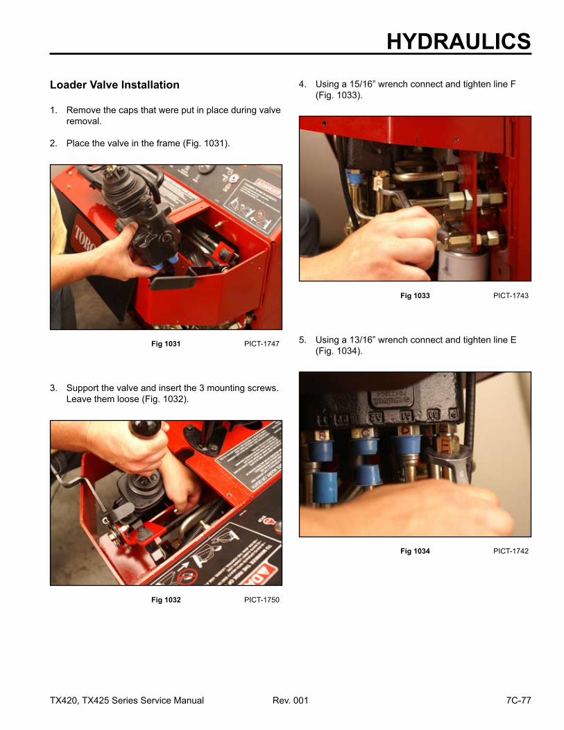
7C-77TX420, TX425 Series Service Manual Rev. 001
Fig 1032 PICT-1750
Fig 1034 PICT-1742
3. Support the valve and insert the 3 mounting screws. Leave them loose (Fig. 1032).
5. Using a 13/16” wrench connect and tighten line E (Fig. 1034).
Fig 1033 PICT-1743
Fig 1031 PICT-1747
4. Using a 15/16” wrench connect and tighten line F (Fig. 1033).
1. Remove the caps that were put in place during valve removal.
2. Place the valve in the frame (Fig. 1031).
Loader Valve Installation

HYDRAULICS
7C-78 Rev. 001 TX420, TX425 Series Service Manual
Fig 1036 PICT-1740 Fig 1038 PICT-1738
7. Using a 13/16” wrench connect and tighten line C (Fig. 1036).
9. Using a 15/16” wrench connect and tighten line A (Fig. 1038).
Fig 1037 PICT-1739 Fig 01035 PICT-1741
8. Using a 13/16” wrench connect and tighten line B (Fig. 1037).
6. Using a13/16” wrench connect and tighten line D (Fig. 1035).

HYDRAULICS
7C-79TX420, TX425 Series Service Manual Rev. 001
Fig 1040 PICT-1731 Fig 1042 PICT-1730
11. Start the engine. Raise and lower the lift cylinders. Also extend and retract tilt cylinder and check for leaks.
12. Install top panel and secure with 4 self tapping screws using a 3/8” socket (Fig. 1040).
14. Install the right side panel. Secure it with 3 self tapping screws using a 3/8” socket (Fig. 1042).
Fig 1041 PICT-1733
Fig 1039 PICT-1746
13. Place the brake cable into the frame slot and tighten bottom nut (Fig. 1041).
Note: Brake cable adjustment - top nut is 3 to 4 threads from the end of threaded stud.
10. Using a 1/2” socket tighten the 3 mounting screws on the front side of the valve (Fig. 1039).

HYDRAULICS
7C-80 Rev. 001 TX420, TX425 Series Service Manual
16. Remove all air from the system. Refer to “Purging Air Procedures” on page 12-27.
Fig 1043 PICT-1729a
15. Install the rear panel (Fig. 1043).
Fig 1044 PICT-2583
1. Before disassembly of any hydraulic component, use a clean, dirt-free work surface and clean solvent to prevent system contamination (Fig. 1044).
TX420 & 425 240000301 & up
Loader Valve Disassembly & Assembly
A. Rubber Bellows D. Spring CapB. System relief E. Detent spring capC. Work port relief (2)
ABC
D E

HYDRAULICS
7C-81TX420, TX425 Series Service Manual Rev. 001
Joystick Assembly Removal
Fig 1045 PICT-2588a
1. Remove the cable tie from around the rubber bellows (Fig. 1045).
Fig 1047 PICT-2591a
3. Using a 6mm Allen wrench, loosen the 3 hex head screws and spring lock washers (Fig. 1047).
Fig 1046 PICT-2589a
2. Remove the rubber bellows from the valve assembly (Fig. 1046). Wipe the excess grease from the joystick.
Fig 1048 PICT-2592a
4. Remove the articulated holder, screws and washers from the valve assembly (Fig. 1048).

HYDRAULICS
7C-82 Rev. 001 TX420, TX425 Series Service Manual
Fig 1051 PICT-2596a
7. Using a 13mm socket and wrench, remove the nut holding the joystick joint and then remove the pivot for the lift and tilt operation (Fig. 1051).
Fig 1050 PICT-2601a
6. Slide the end rod off the pin of the joystick joint for the tilt cylinder (Fig. 1050).
Fig 1049 PICT-2593a
5. Pictured below are the joystick joints (Fig. 1049).
A. Tilt Cylinder operationB. Loader Lift Cylinder operationC. Pivot for Lift and Tilt operation
A
B
C
Fig 1052 PICT-2597
8. Turn the loader lift joystick joint. Using a 3mm Allen wrench, remove the 2 hex head screws securing the joystick pivot to the valve assembly (Fig. 1052).

HYDRAULICS
7C-83TX420, TX425 Series Service Manual Rev. 001
Fig 1053 PICT-2598a
9. Remove the joystick pivot from the valve assembly (Fig. 1053).
Fig 1055 PICT-2598a
2. Position the joystick pivot on the valve assembly (Fig. 1055).
Fig 1054 PICT-2599a
1. Apply thread locking compound on the threads of both screws that secure the pivot to the valve assembly (Fig. 1054).
Joystick Assembly Installation
Fig 1056 PICT-2597
3. Using a 3mm Allen wrench, install the 2 hex head screws that secure the joystick pivot (Fig. 1056).

HYDRAULICS
7C-84 Rev. 001 TX420, TX425 Series Service Manual
Fig 1059 PICT-2601a
6. Slide the end of the joystick joint onto the pin for the tilt cylinder (Fig. 1059).
Fig 1058 PICT-2596a
5. Using a 13mm wrench and socket, tighten the nut securing the joystick joint to the pivot for the lift and tilt operation (Fig. 1058).
Fig 1057 PICT-2600a
4. Position the lift and tilt joystick joint onto the pivot and install the nut (Fig. 1057).
Fig 1060 PICT-2602a
7. Position the articulated holder with 3 hex head screws and lock washers onto the valve assembly and thread the 3 bolts onto the joystick joints (Fig. 1060).

HYDRAULICS
7C-85TX420, TX425 Series Service Manual Rev. 001
Fig 1061 PICT-2603a
8. Torque the 3 bolts to 17.7 ft-lbs. (24 Nm) (Fig. 1061).
Fig 1063 PICT-2605a
10. Position the rubber bellows over the base plate and install the tie strap in the groove of the rubber bellows (Fig. 1063).
Note: When installing the rubber bellows, there is an offset in the bellows. Ensure proper installation.
Fig 1062 PICT-2655
9. Lubricate all of the articulated parts inside the mechanical joystick area with synthetic base grease grade NLGI2 (Fig. 1062).
Fig 1064 PICT-2584a
11. Install the lift/tilt handle (Fig. 1064).

HYDRAULICS
7C-86 Rev. 001 TX420, TX425 Series Service Manual
Fig 1066 PICT-2589a
2. Remove the rubber bellows from the valve assembly (Fig. 1066). Wipe the excess grease from the joystick.
Fig 1065 PICT-2588a
Note: To disassemble and assemble the valve, it is best to hold the valve in a bench vise.
1. Remove the cable tie from around the rubber bellows (Fig. 1065).
Spool Removal
Fig 1068 PICT-2592a
4. Remove the articulated holder, screws and washers from the valve assembly (Fig. 1068).
Fig 1067 PICT-2591a
3. Using a 6mm Allen wrench, loosen the 3 hex head screws and spring lock washers (Fig. 1067).

HYDRAULICS
7C-87TX420, TX425 Series Service Manual Rev. 001
Fig 1070 PICT-2601a
6. Slide the end rod off the pin of the joystick joint for the tilt cylinder (Fig. 1070).
Fig 1069 PICT-2593a
5. Pictured below are the joystick joints (Fig. 1069).
A. Tilt Cylinder operationB. Loader Lift Cylinder operationC. Pivot for Lift and Tilt operation
A
B
C
Fig 1072 PICT-2608a
8. Using a 13mm socket and wrench, remove the nut holding the joystick pivot joint and then remove the pivot for the lift and tilt operation (Fig. 1072).
Fig 1071 PICT-2607a
7. Using a 13mm socket and wrench, remove the nut securing the joystick pin and then remove the pin (Fig. 1071).

HYDRAULICS
7C-88 Rev. 001 TX420, TX425 Series Service Manual
Fig 1074 PICT-2611
10. Using a 3mm Allen wrench, remove the two hex head bolts securing the joystick pivot to the valve assembly (Fig. 1074).
Fig 1073 PICT-2609a
9. Turn the lift pivot. Using a 13mm socket and wrench, remove the nut holding the joystick pivot joint and then remove the joint from the lift and tilt spool (Fig. 1073).
Fig 1076 PICT-2613
12. Remove the joystick base plate from the valve assembly (Fig. 1076).
Fig 1075 PICT-2612
11. Using a 4mm Allen wrench, remove the 2 hex head bolts that secure the joystick base plate to the valve assembly (Fig. 1075).

HYDRAULICS
7C-89TX420, TX425 Series Service Manual Rev. 001
Fig 1078 PICT-2614
14. Turn the valve assembly over. Using a 4mm Allen wrench, remove the two hex head bolts that secure each spring cap to the valve assembly (Fig. 1078).
Fig 1077 PICT-2641
13. Remove the gasket from the valve (Fig. 1077). 15. Remove both caps from the valve assembly (Fig. 1079).
Fig 1079 PICT-2616
16. Using a drift punch to hold the top end of the spool, use a 6mm wrench to remove the detent spring assembly from the bottom of the spool (Fig. 1080).
Fig 1080 PICT-2617

HYDRAULICS
7C-90 Rev. 001 TX420, TX425 Series Service Manual
Fig 1082 PICT-2620a
18. Using a drift punch to hold the top end of the spool, use a 5mm wrench to remove the spring valve assembly from the bottom of the spool (Fig. 1082).
Fig 1081 PICT-2618a
17. Remove the detent spring from the valve assembly (Fig. 1081).
Fig 1084 PICT-2622a
20. Remove the lift spool by twisting and pulling the spool from the valve (Fig. 1084).
Note: Visually inspect spool outside surfaces for scratches. Deep scratches are unacceptable and the spool needs to be replaced. Scratches that are deep enough to catch the fingernailarealsounacceptable,andthespool needs to be replaced.
Fig 1083 PICT-2621a
19. Turn the valve in the vise sideways. Remove the tilt spool by twisting and pulling the spool from the top of the valve (Fig. 1083).

HYDRAULICS
7C-91TX420, TX425 Series Service Manual Rev. 001
Fig 1086 PICT-2628
21. Using a tool with a 90° angle, (for example, a snap ring pliers with 90° tips) remove both the spool valve seals located at the top of the valve (Fig. 1086).
Fig 1085 PICT-2624a
Before replacing the spool, clean and inspect the inner bore for damage. Check the condi-tion of the o-rings, particularly for metallic particles embedded in the o-ring surface. Damage to o-ring grooves, particularly on the sealing surface, is unacceptable. In the event that an unacceptable condition occurs, the valve needs to be replaced (Fig. 1085).
A. Lift Spool with small relief holesB. Tilt Spool
A
B
Fig 1088 PICT-2629
Replace all seals and o-rings with new parts. Lubricate the valve, o-rings, and spool with 10W-30 oil prior to installation (Fig. 1088).
Fig 1087 PICT-2626
22. Remove the two o-rings located at the bottom of the valve; a small dental pick works to help remove the o-rings (Fig. 1087).
Spool Assembly
A. Spring Cap F. Spool Valve Seal (2)B. Tilt Spring G. Lift SpoolC. O-ring (2) H. Detent SpringD. Valve Body I. Detent CapE. Tilt Spool
A BC D
E F
GHI

HYDRAULICS
7C-92 Rev. 001 TX420, TX425 Series Service Manual
Fig 1090 PICT-2631
2. Lubricate and install the spool valve seals in the top of the valve (Fig. 1090).
Note: The thin wall of the seal goes into the valve bodyfirst.
Fig 1089 PICT-2630
1. Lubricate the two o-rings located at the bottom of the valve and install (Fig. 1089).
Fig 1092 PICT-2634
4. Lubricate and install the lift spool in the port closest to the relief, twist and push gently, so you do not damage the o-ring (Fig. 1092).
Fig 1091 PICT-2632
3. Lubricate the tilt spool. Install the spool in the port furthest away from the relief; twist and push gently, so you do not damage the o-ring (Fig. 1091).

HYDRAULICS
7C-93TX420, TX425 Series Service Manual Rev. 001
Fig 1094 PICT-2636
6. Lubricate the spring with synthetic base grease grade NLGI2 (Fig. 1094).
Fig 1093 PICT-2635
5. Install the spring valve assembly with a 5mm hex wrench and torque to 5 ft-lbs. (6.8 Nm) (Fig. 1093).
Fig 1096 PICT-2638
8. Lubricate the spring with synthetic base grease grade NLGI2 (Fig. 1096).
Fig 1095 PICT-2637
7. Install the detent spring assembly and torque to 5 ft-lbs. (6.8 Nm) (Fig. 1095).

HYDRAULICS
7C-94 Rev. 001 TX420, TX425 Series Service Manual
Fig 1098 PICT-2640
10. Tighten and torque the cap screws to 5 ft-lbs. (6.8 Nm) (Fig. 1098).
Fig 1097 PICT-2639
9. Install the spool caps over the detent and spring valve (Fig. 1097).
Fig 1100 PICT-2643
12. Position the joystick base plate over the spools and onto the gasket (Fig. 1100).
Fig 1099 PICT-2641
11. Rotate the valve in the bench vise. Install the gasket over the spools and onto the valve assembly (Fig. 1099).

HYDRAULICS
7C-95TX420, TX425 Series Service Manual Rev. 001
Fig 1102 PICT-2599a
14. Apply thread locking compound to the 2 screws that will secure the pivot to the valve (Fig. 1102).
Fig 1101 PICT-2644
13. Secure the base plate with 2 cap screws and tighten using a 4mm Allen wrench (Fig. 1101).
Fig 1104 PICT-2648a
16. Apply thread locking compound to the threads of the loader lift joystick joint (Fig. 1104).
Fig 1103 PICT-2646
15. Position the pivot onto the base plate and install the 2 screws, using a 3mm Allen wrench, to secure the pivot to the base plate. Torque the 2 screws to 7 ft-lbs. (9.5 Nm) (Fig. 1103).

HYDRAULICS
7C-96 Rev. 001 TX420, TX425 Series Service Manual
Fig 1106 PICT-2650a
18. Apply thread locking compound to the threads of the pivot joystick joint (Fig. 1106).
Fig 1105 PICT-2649a
17. Position the loader lift joystick joint into the lift spool and install the nut. Torque the nut to 31 ft-lbs. (42 Nm) (Fig. 1105).
Fig 1108 PICT-2652a
20. Apply blue thread locking material to the threads of the joystick pin (Fig. 1108).
Fig 1107 PICT-2651a
19. Position the pivot joystick joint into the pivot and install the nut. Torque the nut to 31 ft-lbs. (42 Nm) (Fig. 1107).

HYDRAULICS
7C-97TX420, TX425 Series Service Manual Rev. 001
Fig 1110 PICT-2654
22. Install the end rod onto the joystick pin (Fig. 1110).
Fig 1109 PICT-2653a
21. Position the joint pin into the tilt spool and install the nut. Torque the nut to 31 ft-lbs. (42 Nm) (Fig. 1109).
Fig 1112 PICT-2603a
24. Torque the 3 bolts to 17.7 ft-lbs. (24 Nm) (Fig. 1112).
Fig 1111 PICT-2602a
23. Position the articulated holder with 3 hex head screws and lock washers onto the valve assembly and thread the 3 bolts onto the joystick joints (Fig. 1111).

HYDRAULICS
7C-98 Rev. 001 TX420, TX425 Series Service Manual
Fig 1114 PICT-2605a
26. Position the rubber bellows over the base plate and install the tie strap in the groove of the rubber bellows (Fig. 1114).
Note: When installing the rubber bellows, there is an offset in the bellows. Ensure proper installation.
Fig 1113 PICT-2655
25. Lubricate all of the articulated parts inside the mechanical joystick area with synthetic base grease grade NLGI2 (Fig. 1113).
Fig 1116 PICT-2658
Pressure relief is designed to prevent internal fluid pressure from rising above a pre-determined maximum pressure.
1. Using a 24mm socket and wrench, loosen the body of the main relief valve from the main relief valve bonnet (Fig. 1116).
Fig 1115 PICT-2584a
27. Install the lift/tilt handle (Fig. 1115).
Main Relief Valve

HYDRAULICS
7C-99TX420, TX425 Series Service Manual Rev. 001
2. Using a 24mm wrench, remove the main relief valve from the valve assembly (Fig. 1117).
Fig 1117 PICT-2656
3. Remove the main relief valve assembly from the valve (Fig. 1118).
Fig 1118 PICT-2657a
Fig 1120 PICT-2659a
The relief valve is used to adjust to the specified system pressure (2400 + 50 psi or 165.47 + 3.45 bar) by increasing or decreasing the load on the spring against the disc. Loosen the lock nut; turn screw inward to increase the pressure or outward to decrease the pressure (Fig. 1120).
Fig 1119 PICT-2661a
4. Disconnect the body of the main relief valve from the main relief valve bonnet (Fig. 1119).
A. Bonnet F. Spring spacerB. Set screw lock nut G. BodyC. Set screw H. Body o-ringD. Set screw o-ring I. Back up o-ringE. Spring J. O-ring
A
B
CD
EF
G
H JI

HYDRAULICS
7C-100 Rev. 001 TX420, TX425 Series Service Manual
Fig 1122 PICT-2657a
6. Using a 24mm wrench, install the main relief valve into the valve assembly (Fig. 1122).
Fig 1121 PICT-2661a
5. Connect the body of the main relief valve to the main relief valve bonnet (Fig. 1121).
Fig 1124 PICT-2664
The work relief ports relieve the fluid spikes when the Lift and Tilt Cylinders are being actuated.
These ports are non-adjustable. Port relief setting is 2030 psi (140 bar) (Fig. 1124).
Fig 1123 PICT-2658
7. Using a 24mm socket and wrench, tighten the body of the main relief valve onto the main relief valve bonnet (Fig. 1123).
Work Port Relief

HYDRAULICS
7C-101TX420, TX425 Series Service Manual Rev. 001
Fig 1126 PICT-2668a
Fig 1125 PICT-2663
1. Using a 10mm Allen wrench, remove the 2 work port relief plugs (Fig. 1125 and Fig. 1126).
A. Relief C. O-ringB. Spring D. Plug
A B C D
Fig 1128 PICT-2671
3. Install both springs into the valve work ports (tapered end of the spring goes in first) (Fig. 1128).
Fig 1127 PICT-2667
2. Install both seats and reliefs into the valve work ports (Fig. 1127).

HYDRAULICS
7C-102 Rev. 001 TX420, TX425 Series Service Manual
Fig 1130 PICT-2583
Note: There are 3 “blank” ports on the valve that have plugs with o-rings inserted into them (Fig. 1130).
Fig 1129 PICT-2663
4. Install both work port relief plugs. Tighten using a 10mm Allen wrench (Fig. 1129).
Note: Port reliefs are set at 3050 psi (210 bar). Port reliefs relieve static pressure from the tilt cylinder.