Hydraulic Tail Trailer - Fontaine Heavy-Haul · Traverse trailer. The Fontaine Traverse trailer is...
33
Hydraulic Tail Trailer User Guide and Parts List Fontaine Trailer 5398 Highway 11 Springville, AL 35146 (205) 467-6171
Transcript of Hydraulic Tail Trailer - Fontaine Heavy-Haul · Traverse trailer. The Fontaine Traverse trailer is...
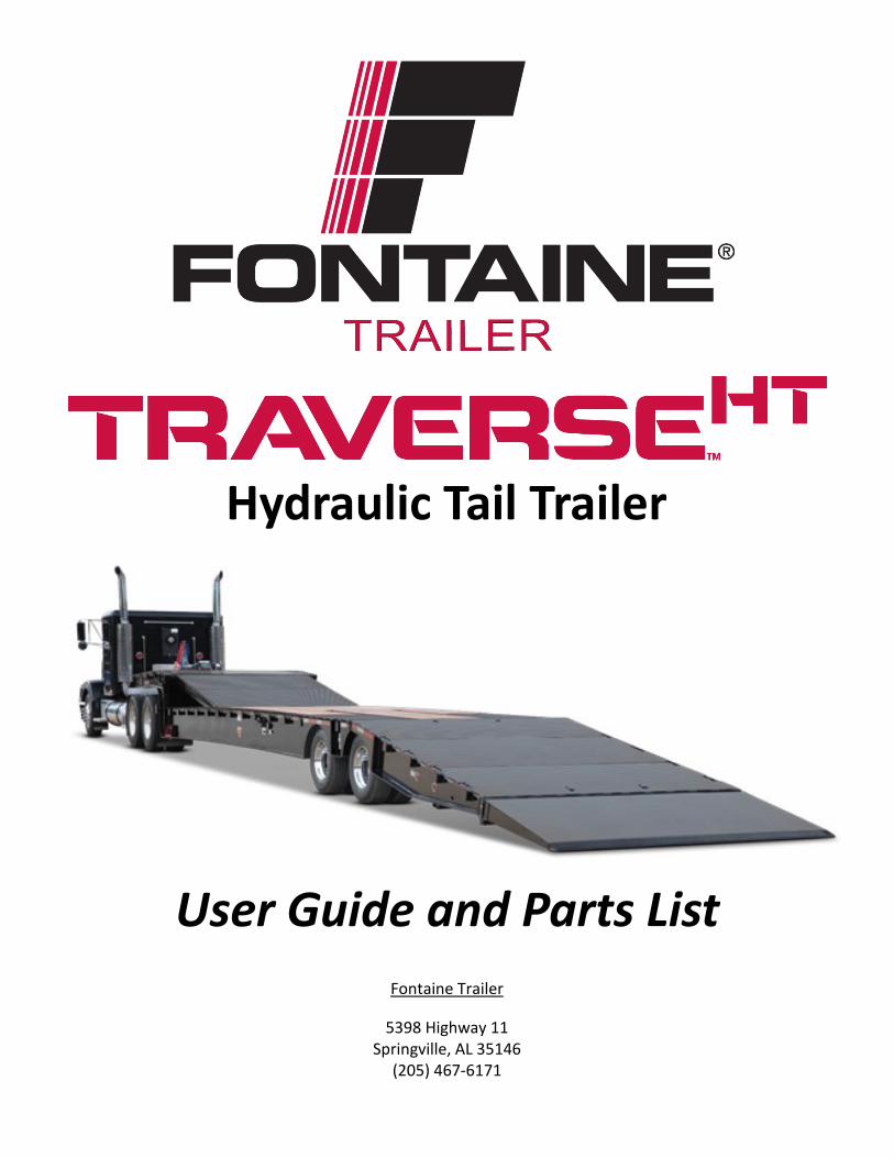
Hydraulic Tail Trailer
User Guide and Parts List
Fontaine Trailer
5398 Highway 11 Springville, AL 35146
(205) 467-6171

i-1
Fontaine Trailer Traverse User Guide and Parts List
Disclaimer
All information in this manual is based on the latest information available at the time of publishing. The illustrations used in this manual are intended as representative reference views. Because of our continuous product improvement policy, we may update content, illustrations and/or specifications to explain and/or clarify a product, service or maintenance improvement. We reserve the right to make any change at any time without notice.
©2015 Fontaine Trailer
Fontaine Trailer reserves all copyright and other rights in this manual and the manual’s content. No part of this manual may be reproduced or used in any way without the written permission of Fontaine Trailer, except as necessary to operate Fontaine Trailer equipment.
Dealer Contact Information For information regarding the operation, service or parts for this product, please contact the Fontaine Trailer dealer from which you purchased the trailer. If you have additional needs, contact Fontaine directly. Refer to page 1-1 for contact information.
Dealer name: ______________________________________________________________________________
Dealer address: ____________________________________________________________________________
Dealer phone number: ______________________________________________________________________
Trailer model: _____________________________________________________________________________
Trailer serial number: _______________________________________________________________________
Date of purchase: __________________________________________________________________________
i-2
Fontaine Trailer Traverse User Guide and Parts List
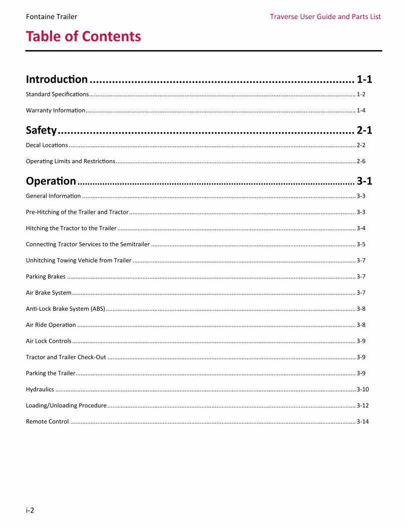
Table of Contents
Introduction ................................................................................... 1-1 Standard Specifications............................................................................................................................................................... 1-2
Warranty Information ................................................................................................................................................................. 1-4
Safety ............................................................................................. 2-1 Decal Locations ........................................................................................................................................................................... 2-2
Operating Limits and Restrictions ............................................................................................................................................... 2-6
Operation ................................................................................................................ 3-1 General Information ................................................................................................................................................................... 3-3
Pre-Hitching of the Trailer and Tractor ....................................................................................................................................... 3-3
Hitching the Tractor to the Trailer .............................................................................................................................................. 3-4
Connecting Tractor Services to the Semitrailer .......................................................................................................................... 3-5
Unhitching Towing Vehicle from Trailer ..................................................................................................................................... 3-7
Parking Brakes ............................................................................................................................................................................ 3-7
Air Brake System ......................................................................................................................................................................... 3-7
Anti-Lock Brake System (ABS) ..................................................................................................................................................... 3-8
Air Ride Operation ...................................................................................................................................................................... 3-8
Air Lock Controls ......................................................................................................................................................................... 3-9
Tractor and Trailer Check-Out .................................................................................................................................................... 3-9
Parking the Trailer....................................................................................................................................................................... 3-9
Hydraulics ................................................................................................................................................................................... 3-10
Loading/Unloading Procedure .................................................................................................................................................... 3-12
Remote Control .......................................................................................................................................................................... 3-14
i-3
Fontaine Trailer Traverse User Guide and Parts List
Introduction
Safety
Operation
Thumb Index
2
3
1

Fontaine Trailer Traverse User Guide and Parts List
1-1
Introduction
PLEASE READ THE ENTIRE MANUAL BEFORE ATTEMPTING TO OPERATE THE TRAILER.
The owner’s manual is an important part of understanding the specialized equipment and must be read prior to operating the trailer. Even if you are familiar with other trailers, it is important that you have a thorough understanding of the Traverse trailer to avoid personal injury or damage to the trailer. If this manual becomes unavailable to you, contact your local, authorized Fontaine dealer to order a replacement.
In this guide, you will find all the information necessary to operate and service your Fontaine Traverse trailer.
The Fontaine Traverse trailer is the industry’s premiere hydraulic tail trailer. It features the lowest deck height and the lowest load angle in the industry. The Traverse features the longest usable main tail, and it’s designed for easily moving equipment for frequent roll-on/roll-off loads. In addition, the Traverse is useful in the equipment recovery industry.
Should you require further assistance, please contact your Fontaine dealer.
This manual is divided into three sections:
The Operations section provides instructions for common use of the trailer.
The Service section outlines instructions for the general upkeep of the trailer. It also contains a troubleshooting guide and schematics.
The Parts List includes a listing of available parts, both standard and optional, for the trailer, as well as ordering information.
A separate Table of Contents for each section can be found at the start of the section.
If you are viewing this manual as a PDF on a computer, you may search for specific content by pressing the keys CTRL and F simultaneously. You may also jump to specific pages by clicking on items in the Thumb Index and Table of Contents.
For additional information and support for the Traverse, please contact Fontaine Trailer using one of the methods listed below:
Phone: (205) 467-6171 Toll-free: (800) 633-6551 Warranty: (866) 382-7278
Email: [email protected] For warranty inquires: [email protected] Part Source: [email protected]
Website: www.fontaineheavyhaul.com Fontaine Trailer 5398 Highway 11 Springville, AL 35146
1

Fontaine Trailer Traverse User Guide and Parts List
1-2
Capacity 40 tons (tandem) distributed evenly and 25 tons in 10 feet – GAWR and tire ratings determine legal loads
Load Base 10-foot rigid 2-point load centered in deck span
Framework All main longitudinal members fabricated with 100,000# minimum yield steel flanges with 50,000# webs
Length 48 feet
Width 102 inches
Gooseneck Design Fixed full width with slope
Gooseneck Platform Full width gooseneck platform with 1 3/8-inch wood floor
Loaded Fifth Wheel Height
49 inches
Swing Radius 85 inches
Power Source Set up for wet line operation. Auxiliary power unit available
Winch Located at front of gooseneck with EIPS wire rope and hook. 18K standard. 20K and 30K options with 2-speed
Radio Remote Control
Wireless convenience for main functions available
Landing Gear 2-speed OEM Standard with road-side crank handle
Tool Box Located on both sides of gooseneck
Electrical Receptacle J560 7-pin connector
Deck Design Flat level deck design
Loaded Deck Height 35 inches with 15 inches ground clearance
Flooring 1 3/8-inch nominal wood (full width)
Crossmembers 18 inch centers - 8-inch and 10-inch jr I-steel
Tie Downs Double key hole chain slots on 24-inch centers with stake pockets
Deck to Ramp Connections
Dual-acting hydraulic cylinders with reliefs for down pressure control
Number of axles 2
Axle Capacity 25,000 pounds nominal capacity per axle
Axle Spread 49 inches (between axles)
Brakes 12.25 inches x 7.5 inches with 6-inch autoslacks, heavy-duty brake drums, outboard mount, and 20,000-pound capacity
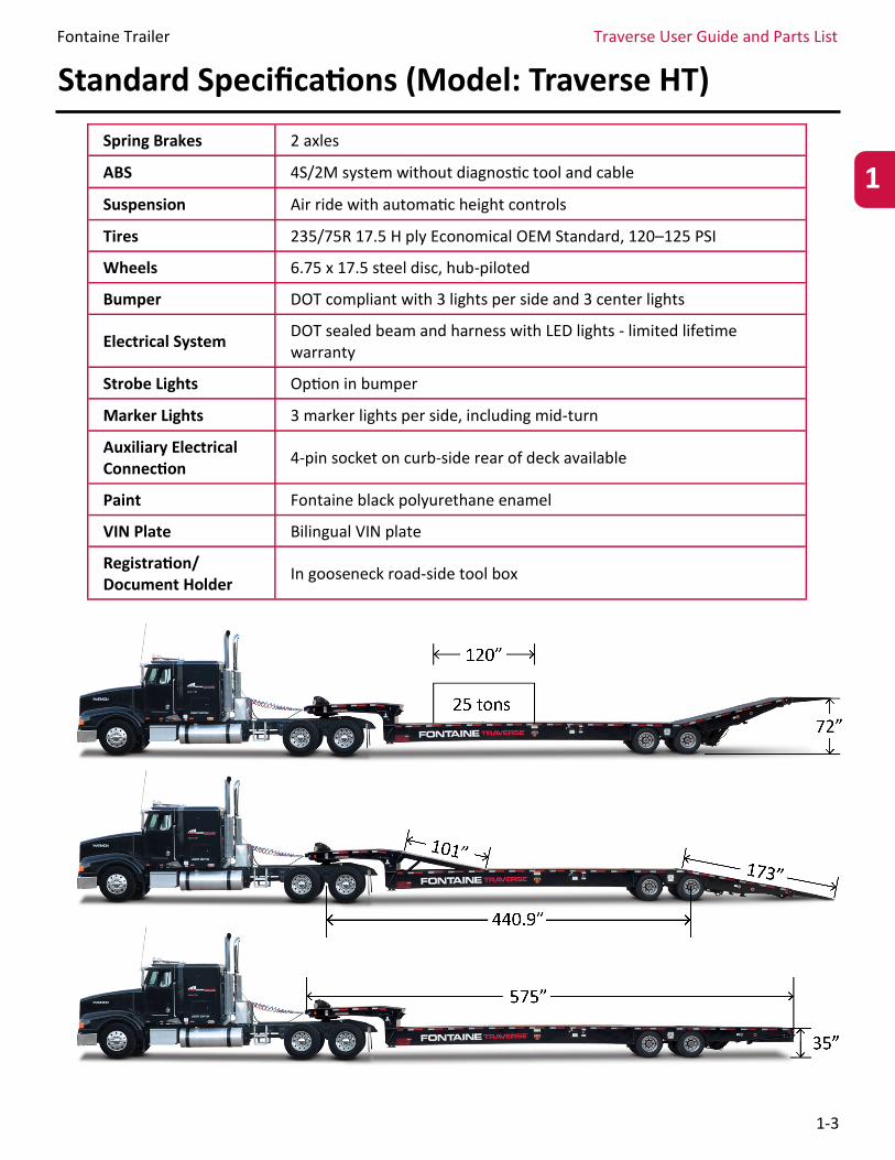
Standard Specifications (Model: Traverse HT)
Fontaine Trailer Traverse User Guide and Parts List
1-3
Spring Brakes 2 axles
ABS 4S/2M system without diagnostic tool and cable
Suspension Air ride with automatic height controls
Tires 235/75R 17.5 H ply Economical OEM Standard, 120–125 PSI
Wheels 6.75 x 17.5 steel disc, hub-piloted
Bumper DOT compliant with 3 lights per side and 3 center lights
Electrical System DOT sealed beam and harness with LED lights - limited lifetime warranty
Strobe Lights Option in bumper
Marker Lights 3 marker lights per side, including mid-turn
Auxiliary Electrical Connection
4-pin socket on curb-side rear of deck available
Paint Fontaine black polyurethane enamel
VIN Plate Bilingual VIN plate
Registration/Document Holder
In gooseneck road-side tool box
Standard Specifications (Model: Traverse HT)
1
Fontaine Trailer Traverse User Guide and Parts List
1-4
Warranty Information
Lowbed, Extendable and Specialty Trailer Limited Warranty Fontaine Trailer Company (“Fontaine”) warrants to the first user only (“First User”) that each new lowbed, extendable and specialty trailer (“Trailer”) manufactured by Fontaine will be free from defects in materials and workmanship for twelve (12) months from the delivery of the Trailer to First User. In addition, Fontaine warrants to First User that the main structural members and supports of the Trailer will be free from defects in material and workmanship for twenty-four (24) months from the date of delivery of Trailer to First User.
This Limited Warranty does not apply to and does not cover defects in material and workmanship due to or in any way arising out of:
Failure to properly maintain the Trailer or any other improper maintenance of the Trailer;
Abnormal use and service, including (without limitation) loading, unloading and/or transportation of non-uniformly distributed loads, use with corrosive cargo, and/or failure to adequately restrain or secure loads such that the Trailer is subjected to strains or impacts greater than are imposed by normal use;
Total weight of Trailer and cargo exceeding the gross vehicle weight rating (GVWR) stated on the vehicle identification plate affixed to the Trailer by Fontaine or the loading of each axle exceeding the gross axle weight rating (GAWR) listed on the vehicle identification plate;
Accidents;
Any other misuse or negligence.
In addition, this Limited Warranty does not cover:
Tires;
Except with respect to title, used goods sold by Fontaine, all of which are sold "as is";
Except with respect to title, items or parts not manufactured by Fontaine; provided, that Fontaine will, as an accommodation to First User, pass on to First User any warranty it receives from the manufacturer of such items or parts, but only to the extent allowed by such manufacturer;
Trailers which have been repaired or altered by anyone other than an authorized repair facility approved by Fontaine, unless in Fontaine’s sole and exclusive judgment, such repairs are in no way responsible for the condition complained of; and
Parts which are not defective but which wear out under normal use, such as (but not limited to) light bulbs, electrical receptacles, paint and coatings, brakes, linings, drums and return springs, equalizers, torque rod and camshaft bushings, camshafts, slack adjusters, brake cylinder diaphragms, springs, slider pads, wheel bearings, oil and oil seals, rim clamps and studs, gaskets and sealers, and all types of floors and floor boards.
If First User notifies Fontaine in writing within the applicable warranty period of a defect in the Trailer and Fontaine determines, after such tests and/or inspections as Fontaine deems appropriate, that such Trailer or part is not in conformity with this Limited Warranty, Fontaine will repair or replace, at its sole option, such defective Trailer or part, provided First User returns such Trailer or part to such repair facility as may be designated by Fontaine, freight prepaid. No Trailer or part shall be returned without Fontaine's prior approval. This shall be First User's exclusive remedy for Fontaine's liability hereunder. Any claims not made within the applicable warranty period are deemed waived by First User. In lieu of repairing or replacing the defective Trailer or part, Fontaine
Fontaine Trailer Traverse User Guide and Parts List
1-5
Warranty Information (cont.)
may, at its sole option, refund the purchase price of such Trailer or part.
THIS IS FONTAINE’S ONLY WARRANTY. FONTAINE MAKES NO OTHER WARRANTY OF ANY KIND WHATSOEVER, EXPRESS OR IMPLIED. ALL IMPLIED WARRANTIES OF MERCHANTABILTY AND/OR FITNESS FOR A PARTICULAR PUPROSE ARE HEREBY DISCLAIMED BY FONTAINE AND EXCLUDED.
Fontaine's liability to First User, or anyone claiming through or on behalf of First User, with respect to any claim or loss arising out of the Trailer or alleged to have resulted from an act or omission of Fontaine, whether negligent or otherwise, and whether in tort, contract, or otherwise, including failure to deliver, delay in delivery, or breach of warranty, shall be limited to an amount equal to the purchase price of the Trailer or part with respect to which such liability is claimed or, where appropriate and at the option of Fontaine, to repair or replacement of the Trailer or part. In no event shall Fontaine be liable for any bodily injury, death, or property damage resulting from or in any way arising out of the Trailer or its sale, use, or manufacture or for any cargo loss or loss of use. Fontaine is not responsible for any financial loss due to lack of use of the Trailer or any expenses arising therefrom, including but not limited to lodging, fuel, towing, loss of revenue and other expenses or damages. IN NO EVENT SHALL FONTAINE BE LIABLE FOR INCIDENTAL OR CONSEQUENTIAL DAMAGES, LOSSES, OR EXPENSES.
This Limited Warranty may not be changed except in writing by an authorized officer of Fontaine.
THE PROVISIONS OF THIS LIMITED WARRANTY SHALL BE INTERPRETED AND GOVERNED UNDER THE LAWS OF THE STATE OF ALABAMA. This Limited Warranty gives you specific rights, and you may also have other rights which vary from state to state. To facilitate coverage under this Limited Warranty, register the Trailer in Fontaine’s
warranty system at http://fontainetrailer.com/warranty/.
For more information on Fontaine products, please visit www.fontainetrailer.com.
1

Fontaine Trailer Traverse User Guide and Parts List
2-1
Safety
You must read and understand these guidelines before operating the trailer. Throughout this guide you will see a variety of color-coded safety indicators as detailed below. The indicators will provide important information for the proper care and usage of your trailer. It is vital that you familiarize yourself with the proper safety procedures to avoid personal injury or harm to the Traverse trailer.
Potential Safety Incidents Most Hydraulic Tail trailer incidents occur when unloading a load, when the ramps or tails are lowered unexpectedly or when a raised platform/load contact electrical lines. However, other accidents can occur.
Emptying a Load Anytime the platform of the trailer is raised, it places workers at risk unless hazardous situations are controlled or eliminated. Operators need to understand that the trailer is at a risk for a tipping incident when the platform is raised because raising the platform changes the trailer’s center of gravity. Even if the operating area is relatively flat, a tipping incident could occur if a slope is created by low tire pressure on one side or one set of tires sitting in a low area or a depression. Additional hazards that can increase the risk of a tipping incident include wind, loads that are not centered and jack-knifed trailers. The longer the trailer, the more surface area is exposed to high winds, placing lateral pressure on the trailer and creating the potential for a tipping incident.
When loading the platform of the trailer, evenly distribute the contents to maintain proper loading and prevent the load from shifting during unloading. When unloading, if the bed is raised too quickly, the shift of the load could damage the lift mechanism or cause the trailer and truck to tip over.
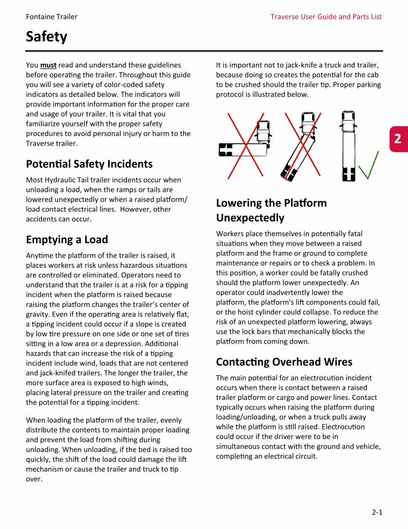
It is important not to jack-knife a truck and trailer, because doing so creates the potential for the cab to be crushed should the trailer tip. Proper parking protocol is illustrated below.
Lowering the Platform Unexpectedly Workers place themselves in potentially fatal situations when they move between a raised platform and the frame or ground to complete maintenance or repairs or to check a problem. In this position, a worker could be fatally crushed should the platform lower unexpectedly. An operator could inadvertently lower the platform, the platform's lift components could fail, or the hoist cylinder could collapse. To reduce the risk of an unexpected platform lowering, always use the lock bars that mechanically blocks the platform from coming down.
Contacting Overhead Wires The main potential for an electrocution incident occurs when there is contact between a raised trailer platform or cargo and power lines. Contact typically occurs when raising the platform during loading/unloading, or when a truck pulls away while the platform is still raised. Electrocution could occur if the driver were to be in simultaneous contact with the ground and vehicle, completing an electrical circuit.
2
Fontaine Trailer Traverse User Guide and Parts List
2-2
Additional Hazards Slips, falls and crushing incidents can occur when working around this trailer. Workers should make sure that the steps are clean of mud and debris and should use the handrails when accessing the truck and trailer. Crushing injuries to fingers and hands may result from opening and closing latches. More severe crushing injuries can occur when a worker is between the trailer or truck and a building or other structure.
Another potential hazard is a tip-over hazard, which may occur when the truck/trailer operates near a ditch bank. The vehicles can place considerable pressure on the banks of ditches or open excavations and the shoulder lanes alongside fields or excavations. If the soil on the shoulder is weak from freezing and thawing or prolonged wet weather, the weight could result in soil collapse and a potential tipping incident. To prevent this, keep your vehicle 300 feet or more from the edge of the ditch or drop-off.
Signal Words
Make sure you read and understand all the information contained in this guide and on the trailer’s decals before attempting to operate or maintain this trailer.
Decal Locations The Traverse trailer is equipped with safety decals that must never be ignored. Keep all safety labels in sound condition. Replacements are available from your Fontaine dealer (see contact information on page 1-1).
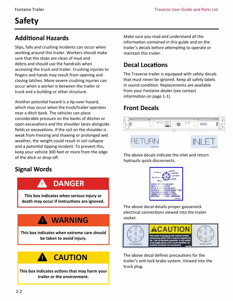
Front Decals
The above decals indicate the inlet and return hydraulic quick disconnects.
The above decal details proper gooseneck electrical connections viewed into the trailer socket.
The above decal defines precautions for the trailer’s anti-lock brake system. Viewed into the truck plug.
Safety
This box indicates when serious injury or death may occur if instructions are ignored.
This box indicates when extreme care should be taken to avoid injury.
This box indicates actions that may harm your trailer or the environment.
Fontaine Trailer Traverse User Guide and Parts List
2-3
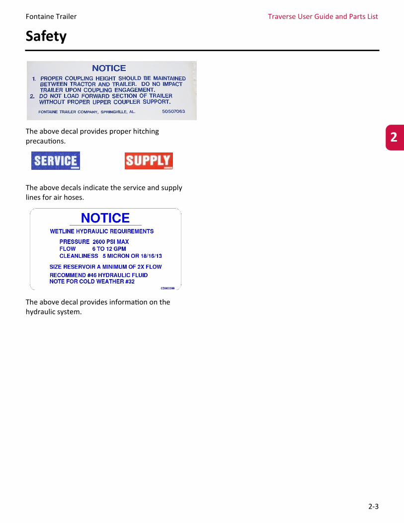
The above decal provides proper hitching precautions.
The above decals indicate the service and supply lines for air hoses.
The above decal provides information on the hydraulic system.
Safety
2
Fontaine Trailer Traverse User Guide and Parts List
2-4
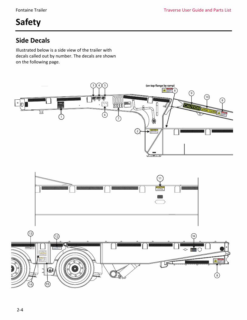
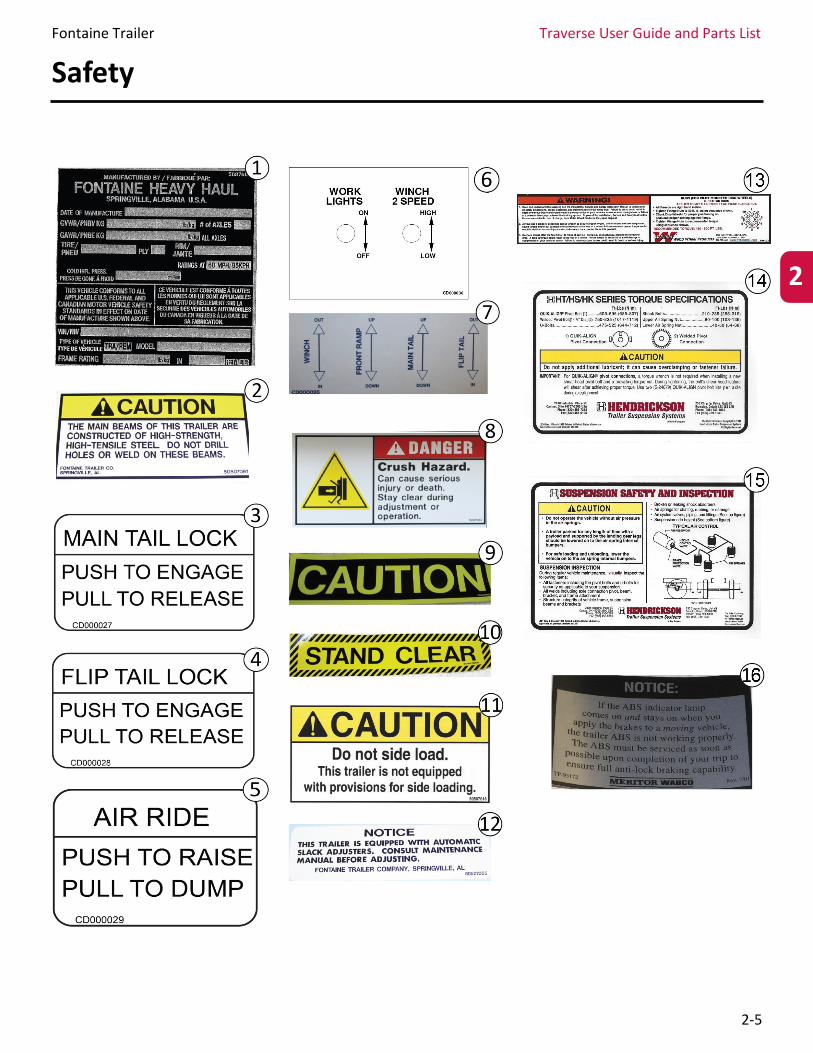
Side Decals Illustrated below is a side view of the trailer with decals called out by number. The decals are shown on the following page.
Safety
Fontaine Trailer Traverse User Guide and Parts List
2-5
Safety
2
Fontaine Trailer Traverse User Guide and Parts List
2-6
Operating Limits and Restrictions This Fontaine trailer was designed for operation within legal highway speed limits on reasonable road surfaces for the type of service it was built to perform in accordance with the following:
1. This trailer was built to carry cargo within the limitations of two weight ratings on the identification plate. These ratings, GAWR and GVWR, are:
• The GAWR (gross axle weight rating) is the structural capability of the lowest rated member of the running gear components: suspensions, hub, wheels and drums, rims, bearings, brakes, axles or tires.
The GVWR (gross vehicle weight rating) is the maximum combined weight of the vehicle and its payload based upon structural capability alone. The trailer structural capability is when the trailer is supported by the kingpin and axles with the load uniformly distributed throughout the cargo space, as defined by the VIN plate.
2. The cargo should be properly loaded, blocked and braced to prevent load shifts and to comply with the following sections of the Department of Transportation Regulations, Subpart 1 – Protection against Shifting and Falling Cargo:
• Section 393.100 – General rules for protection against shifting or falling cargo.
Section 393.102 – Securement systems. To properly secure cargo, it is important that the working load limits of the tie downs be known, as well as the working load limit of the anchor points.
NOTE: The maximum load indicated on the identification plate may or may not be a legal load on the highway you plan to use.
Section 393.104 – Blocking and bracing.
Section 393.106 – Front-end structure. Your trailer may or may not be equipped with a “rated” bulkhead. It is your responsibility to ensure compliance with 393.106.
Beginning March 1, 1998 all trailers are required by law to have anti-lock brake systems on at least one axle per FMVSS-121 (49CFR 571.121). A “4S-2M” system means there are 4 sensors and 2 modulator valves controlling the axles while a “2S-1M” system is 2 sensors and 1 modulator valve. Refer to the manufacturer of the ABS system for specific information on the various components.
Safety
Fontaine Trailer Traverse User Guide and Parts List
3-1
Operation
3
Expanded Table of Contents
General Information ................................................................................................ 3-3
Pre-Hitching of the Trailer and Tractor ............................................................ 3-3
Hitching the Tractor to the Trailer...................................................................... 3-4
Connecting Tractor Services to the Trailer ...................................................... 3-5
Electrical System .......................................................................................................... 3-5
Rear Strobe Light (Optional) ........................................................................................ 3-6
Auxiliary Power Socket (Optional) ................................................................................ 3-6
Unhitching the Tractor to the Trailer ................................................................ 3-7
Parking Brakes ........................................................................................................... 3-7
Air Brake System ....................................................................................................... 3-7
Anti-Lock Brake System (ABS) .............................................................................. 3-8
Air Ride Operation ................................................................................................... 3-8
Air Lock Controls ....................................................................................................... 3-9
Tractor and Trailer Check-Out ............................................................................. 3-9
Parking the Trailer .................................................................................................... 3-9
Hydraulics .................................................................................................................... 3-10
Winch Controls ............................................................................................................ 3-10
Front Ramp Lever ........................................................................................................ 3-11
Main Tail Lever ............................................................................................................. 3-12
Flip Tail Lever ............................................................................................................... 3-12
Fontaine Trailer Traverse User Guide and Parts List
3-2
Operation
Table of Contents (Continued)
Loading/Unloading Procedure ............................................................................ 3-12
Remote Control ......................................................................................................... 3-14
Fontaine Trailer Traverse User Guide and Parts List
3-3
Operation
General Information This section will provide information detailing the general operation procedures for the semitrailer, including location of different controls and their separate functions. Training is required. Take care to read all instructions, notes and warnings before operating the trailer. Refer back to the Introduction for a detailed explanation of the color-coded safety warnings (page 2-2).
Pre-hitching of the Trailer and Tractor
1. Put the tractor directly in front of the trailer. Align the tractor with the trailer. Never back the tractor under the trailer at an angle. This may cause damage to the trailer. Back slowly until the fifth wheel is within close proximity to touching the trailer. Shift the transmission to neutral, and apply the tractor park brake.
2. Inspect the fifth wheel assembly and truck frame to ensure that the proper hitch mounting, maintenance and position are within specification and ready to be hitched. Inspect the trailer kingpin plate. Evaluate the kingpin for proper maintenance and wear. The plate should be level with the fifth wheel, and the pin center aligned with the tractor’s fifth wheel.
3. The trailer should be low enough so that it is raised slightly by the tractor when the tractor is backed under it. Adjust the trailer height as needed using the landing gear.
4. The landing gear crank handle is located on the road-side of the gooseneck. Turning the handle clockwise will lower the landing gear, and counterclockwise will raise it. The landing gear is a 2-speed assembly. Pushing the handle inboard before turning will engage a faster set of gears. Pulling outboard on the handle will slow the speed and allow more power to lift the front of the trailer.
5. Inspect the area around the tractor and trailer. There needs to be clear area around both vehicles. Properly chock the trailer wheels, and ensure that any cargo load is properly secured.
Do not operate the trailer with any known fault that may endanger the user, those
nearby, other traffic, the load, or the equipment.
Do not operate the trailer until you have read the manual and have a complete
understanding for the uses of your trailer and the controls. Improper use may cause
personal injury, damage to your trailer and/or cargo, as well as
unnecessary repairs.
Check the area around the tractor and trailer for bystanders or foreign objects. Failure to have a clear area can cause injury, death, or
property damage.
3
Incorrect trailer height may result in damage to the kingpin, or not allow the tractor and
trailer to couple correctly.
Fontaine Trailer Traverse User Guide and Parts List
3-4
Operation
6. Inspect the gladhand seals on the airlines. Connect the red emergency line from the tractor to the red supply line on the front of the trailer. Connect the blue service line from the tractor to the blue service line on the front of the trailer. Make sure airlines are supported where they cannot be damaged while the tractor is backing under the trailer. Check the trailer air brake operation by applying and releasing the brakes from the control valve in the tractor. Listen for the sound of the trailer brakes being applied and released. Inspect the brake action on all trailer brakes for proper function at each brake.
Hitching the Tractor to the Trailer
1. Follow pre-hitching methods previously listed. Make sure to inspect both the tractor and trailer, chock the trailer wheels and verify the trailer park brakes are engaged.
2. Ensure the tractor fifth wheel coupler is open by pulling the latch handle. Check that the trailer height is correct for hitching, and confirm the tractor alignment with the trailer.
3. Back the tractor slowly under the trailer to avoid severely impacting the kingpin. Stop
when the kingpin is locked into the fifth wheel.
4. Shift the transmission to neutral and set the park brakes. Inspect the coupling. Make sure the fifth wheel jaws have closed around the shank of the kingpin. Check that the locking lever is in the “Lock” position. If the tractor is not coupled correctly follow the procedure for uncoupling and repeat the hitching procedure.
5. Raise the landing gear slightly off the ground. Release the tractor park brakes only, and slowly pull the tractor forward a few inches while the trailer brakes are still engaged. The fifth wheel should be locked at this time and the trailer should prevent tractor movement. If the tractor disconnects stop, park the tractor, and investigate. Correct the cause of the mis-couple and repeat the Hitching procedure.
6. Shift the transmission to neutral, set the park brakes and shut off the engine. Inspect the coupling to be sure the jaws are closed on the shank and the locking lever is in the “Lock” position.
Do not walk or stand between the tractor and trailer. Tractor movement can cause serious
injury or death.
Incorrect coupling procedures can result in accidents causing injury or death. Not all
tractors are identical. Be aware of the differences in the vehicles you operate.
Never back a tractor under a trailer at an angle or move the trailer while the landing
gear is down. Moving the trailer sideways or while the landing gear is down can damage the landing gear or other structures of the
trailer.
Make sure the parking brakes are engaged and the tractor cannot be moved before
placing any part of your body between the tractor and trailer. Tractor movement can
cause serious injury or death.
Fontaine Trailer Traverse User Guide and Parts List
3-5
Operation
Connecting Tractor Services to the Trailer 1. Plug the electrical cord into the front of the
trailer, and fasten the safety catch. The electrical connector has a keyed slot to help guide the correct alignment.
2. Visually inspect to see that the ABS light functions correctly when the power cord is connected. If the light stays on or comes on during use, have the ABS unit repaired at once.
3. If not already connected from the pre-hitch operation, connect the air lines. Inspect the gladhand seals on the airlines. Connect the red supply line from the tractor to the red supply line on the front of the trailer. Connect the blue service line from the tractor to the blue service line on the front of the trailer.
4. Make sure air and electrical lines will not be crushed or damaged by any moving parts.
5. If the truck is equipped with a hydraulic system, first ensure that the hydraulic system is off and there is no remaining pressure in the hydraulic supply lines. Also check the trailer lines, and move the hydraulic valve handles located on the road-side of the gooseneck to relieve any remaining pressure. Connect the hydraulic supply and return lines to the quick disconnect couplers on the front of the gooseneck to the left of the electrical connector.
Note: This Hydraulic Tail trailer requires a hydraulic supply system that is limited to 2600 psi max operating pressure and a flow rate of 6 to 12 gallons per minute. Oil cleanliness should be to 5 microns, or 18/16/13, for a trailer equipped with a remote control hydraulic valve. The minimum reservoir capacity should have enough space to accept an additional 2 gallons of oil that is displaced from the trailer hydraulic system, plus 2 times the flow capacity of the pump. For example, if the pump will flow 10 gpm, then the minimum oil level needs to be approximately 20 gallons, and the minimum tank size needs to be approximately 22 gallons. 6. Make sure the hydraulic lines will not be
crushed or damaged by any moving parts.
7. Fully raise the landing gear. The landing gear crank handle is located on the road-side of the gooseneck. Pull outboard on the handle to ensure the gear set is shifted to the power gears. Once the weight of the trailer is re-leased from the landing gear, push the handle inboard to engage the faster gears. Turn counterclockwise to raise the landing gear.
8. Upon properly completing the final connections of the tractor to the trailer, the motor carrier must perform a USDOT-qualified pre-trip/post-trip inspection.
Electrical System The lighting system for the HT trailer is a heavy-duty, 12-volt, 30-amp system. The 7-way receptacle is located on the front of the trailer near the gladhands. The electrical connector has a keyed slot to help guide the correct alignment. There is a hinge type cover that protects it from exposure. The same light switches that control the lights on the truck tractor control the trailer lights.
Proper maintenance of the lighting system requires periodic cleaning of lamps and reflectors to assure maximum visibility of the tractor and
3
Piercing Hazard. Pressurized fluid can penetrate the skin and result in serious injury.
Do not search for pressure or leaks without proper body and face protection. If you are exposed to high-pressure fluid spray, seek
medical care promptly.
Fontaine Trailer Traverse User Guide and Parts List
3-6
Operation
trailer. Ensure that all wiring connections are tight, lighting is securely installed, and the wiring is protected from pinch or damage.
The trailer is wired to supply constant power to the trailer’s anti-lock brake system (ABS) from the “Center Pin” of the main 7-way connector at the front of the trailer. All electrical circuits are grounded through the white wire of the 7-way to the tractor.
Reflectors are located on the front, sides, and rear sections of the trailer. They should be kept clean. Replace any reflectors or lighting that are missing or damaged.
Turn on the marker and identification lights for the truck and trailer. Be sure that the lights on the side of the trailer are illuminated any time that the hydraulic system is being used. This will alert bystanders. Power for the remote control is provided on the center pin (blue auxiliary wire). Refer to page 3-13 for remote control operation.
The switch on the side of the gooseneck by the air controls is for the 2-speed function on the winch. The winch will operate with normal power limits when the switch is off. By turning on the switch, the winch will operate at a faster speed; however, the power will be reduced. This option is available for some winches.
Rear Strobe Light A rear strobe light option is available for the HT
trailer. The two amber lights will be located in the
rear border on the left and right side between the
Stop/Turn lights. The switch to control the lights is
located on the road-side of the trailer behind the
axles. Turn the switch on to activate the strobe
lights. These lights are powered by an on-board
battery. The battery pack is located on the road-
side of the trailer behind the rear axles. This pack
includes a trickle charger that is connected to the
blue auxiliary wire of the trailer main harness.
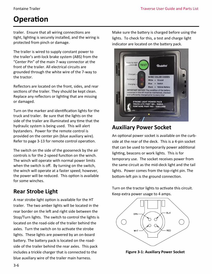
Make sure the battery is charged before using the
lights. To check for this, a test and charge light
indicator are located on the battery pack.
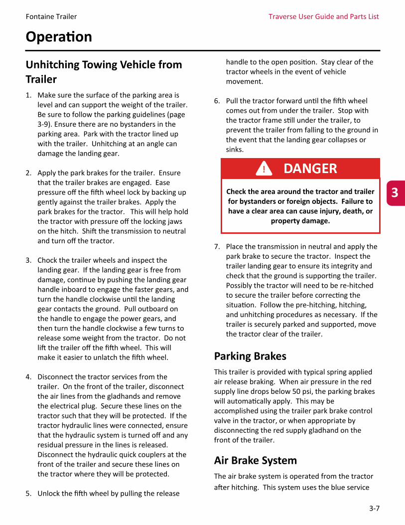
Auxiliary Power Socket An optional power socket is available on the curb-
side at the rear of the deck. This is a 4-pin socket
that can be used to temporarily power additional
lighting, beacons or work lights. This is for
temporary use. The socket receives power from
the same circuit as the mid-deck light and the tail
lights. Power comes from the top-right pin. The
bottom-left pin is the ground connection.
Turn on the tractor lights to activate this circuit.
Keep extra power usage to 4 amps.
Figure 3-1: Auxiliary Power Socket
Fontaine Trailer Traverse User Guide and Parts List
3-7
Operation
Unhitching Towing Vehicle from Trailer 1. Make sure the surface of the parking area is
level and can support the weight of the trailer. Be sure to follow the parking guidelines (page 3-9). Ensure there are no bystanders in the parking area. Park with the tractor lined up with the trailer. Unhitching at an angle can damage the landing gear.
2. Apply the park brakes for the trailer. Ensure that the trailer brakes are engaged. Ease pressure off the fifth wheel lock by backing up gently against the trailer brakes. Apply the park brakes for the tractor. This will help hold the tractor with pressure off the locking jaws on the hitch. Shift the transmission to neutral and turn off the tractor.
3. Chock the trailer wheels and inspect the landing gear. If the landing gear is free from damage, continue by pushing the landing gear handle inboard to engage the faster gears, and turn the handle clockwise until the landing gear contacts the ground. Pull outboard on the handle to engage the power gears, and then turn the handle clockwise a few turns to release some weight from the tractor. Do not lift the trailer off the fifth wheel. This will make it easier to unlatch the fifth wheel.
4. Disconnect the tractor services from the trailer. On the front of the trailer, disconnect the air lines from the gladhands and remove the electrical plug. Secure these lines on the tractor such that they will be protected. If the tractor hydraulic lines were connected, ensure that the hydraulic system is turned off and any residual pressure in the lines is released. Disconnect the hydraulic quick couplers at the front of the trailer and secure these lines on the tractor where they will be protected.
5. Unlock the fifth wheel by pulling the release
handle to the open position. Stay clear of the tractor wheels in the event of vehicle movement.
6. Pull the tractor forward until the fifth wheel comes out from under the trailer. Stop with the tractor frame still under the trailer, to prevent the trailer from falling to the ground in the event that the landing gear collapses or sinks.
7. Place the transmission in neutral and apply the park brake to secure the tractor. Inspect the trailer landing gear to ensure its integrity and check that the ground is supporting the trailer. Possibly the tractor will need to be re-hitched to secure the trailer before correcting the situation. Follow the pre-hitching, hitching, and unhitching procedures as necessary. If the trailer is securely parked and supported, move the tractor clear of the trailer.
Parking Brakes This trailer is provided with typical spring applied air release braking. When air pressure in the red supply line drops below 50 psi, the parking brakes will automatically apply. This may be accomplished using the trailer park brake control valve in the tractor, or when appropriate by disconnecting the red supply gladhand on the front of the trailer.
Air Brake System The air brake system is operated from the tractor
after hitching. This system uses the blue service
3 Check the area around the tractor and trailer for bystanders or foreign objects. Failure to have a clear area can cause injury, death, or
property damage.
Fontaine Trailer Traverse User Guide and Parts List
3-8
Operation
line and should be connected with the gladhand at
the front of the trailer. A minimum service
pressure of 90 psi in the system is required for the
brakes to function properly.
Anti-Lock Brake System (ABS) It is required that constant power for ABS is applied when the tractor key switch is on. The trailer is wired to receive constant power for the anti-lock brake system from the “Center Pin” (blue wire) of the main 7-way connector at the front of the trailer. All electrical circuits are grounded through the white wire of the 7-way to the tractor.
Meritor WABCO anti-lock braking system is standard equipment for this trailer. The system monitors wheel speed at all times and improves vehicle stability and control by reducing wheel lock during braking. In the event of Electronic Control Unit (ECU) malfunction, the ABS in the affected wheels is disabled. The affected wheels should continue to operate in a non-ABS braking mode, if the braking valve itself has not failed. The ABS should continue to operate on the wheels unaffected by the ECU malfunction.
An ABS indicator lamp is provided to let the driver know the status of the system. This amber lamp is located on the road-side (driver side) near the rear marker lamp. The lamp is identified with the letters ABS. It is normal for the lamp to come ON and go OFF when power is supplied to the system. The lamp should not stay on when the brakes are applied or the vehicle is moving faster than 4 miles per hour. If the lamp stays on, there is an ABS malfunction and the system needs to be inspected. It is important not to ignore this
indicator. The vehicle should be serviced using the appropriate Meritor Wabco Maintenance manual to ensure proper braking performance.
Air Ride Operation The trailer is equipped with an automatic leveling air ride suspension. The leveling valve is located in the center of the tandem axle assembly and is set for a loaded ride height of 35 inches measured to the top of the main beams. The loaded trailer kingpin plate height at the fifth wheel is 49 inches. Different tractors fifth wheel heights may affect the leveling of the air suspension. The tractors fifth wheel height must be equal to the designed kingpin height of the trailer. There must be a minimum of 80 psi air pressure in the air reservoir to open the brake protection valve and allow air to flow through the height control valve. A 10-second delay may occur before the height control valve will allow air to flow to or from the air springs.
A manual air suspension dump valve is located on the side of the gooseneck on the road-side. This valve is used during loading and unloading operations. Be sure that this valve is closed (pushed in) so that the air suspension has the appropriate air pressure before moving the trailer.
If ABS fault exists on the trailer, normal braking will occur, but the wheels may lock.
If this occurs, service the ABS as soon as possible. If air loss should occur in the suspension,
there are internal bumpers in the air springs. The manual dump valve can be used to shut off the air loss (pull out). Limited mobility can be used for the system to be repaired. In this condition care should be used to not
overload the axles.
Fontaine Trailer Traverse User Guide and Parts List
3-9
Operation
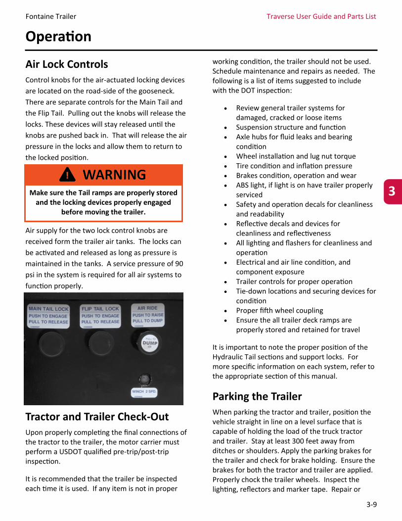
Air Lock Controls Control knobs for the air-actuated locking devices
are located on the road-side of the gooseneck.
There are separate controls for the Main Tail and
the Flip Tail. Pulling out the knobs will release the
locks. These devices will stay released until the
knobs are pushed back in. That will release the air
pressure in the locks and allow them to return to
the locked position.
Air supply for the two lock control knobs are
received form the trailer air tanks. The locks can
be activated and released as long as pressure is
maintained in the tanks. A service pressure of 90
psi in the system is required for all air systems to
function properly.
Tractor and Trailer Check-Out Upon properly completing the final connections of the tractor to the trailer, the motor carrier must perform a USDOT qualified pre-trip/post-trip inspection.
It is recommended that the trailer be inspected each time it is used. If any item is not in proper
working condition, the trailer should not be used. Schedule maintenance and repairs as needed. The following is a list of items suggested to include with the DOT inspection:
Review general trailer systems for damaged, cracked or loose items
Suspension structure and function Axle hubs for fluid leaks and bearing
condition Wheel installation and lug nut torque Tire condition and inflation pressure Brakes condition, operation and wear ABS light, if light is on have trailer properly
serviced Safety and operation decals for cleanliness
and readability Reflective decals and devices for
cleanliness and reflectiveness All lighting and flashers for cleanliness and
operation Electrical and air line condition, and
component exposure Trailer controls for proper operation Tie-down locations and securing devices for
condition Proper fifth wheel coupling Ensure the all trailer deck ramps are
properly stored and retained for travel
It is important to note the proper position of the Hydraulic Tail sections and support locks. For more specific information on each system, refer to the appropriate section of this manual.
Parking the Trailer When parking the tractor and trailer, position the vehicle straight in line on a level surface that is capable of holding the load of the truck tractor and trailer. Stay at least 300 feet away from ditches or shoulders. Apply the parking brakes for the trailer and check for brake holding. Ensure the brakes for both the tractor and trailer are applied. Properly chock the trailer wheels. Inspect the lighting, reflectors and marker tape. Repair or
3 Make sure the Tail ramps are properly stored and the locking devices properly engaged
before moving the trailer.
Fontaine Trailer Traverse User Guide and Parts List
3-10
Operation
replace as needed to properly identify the trailer. Check for any air leaks.
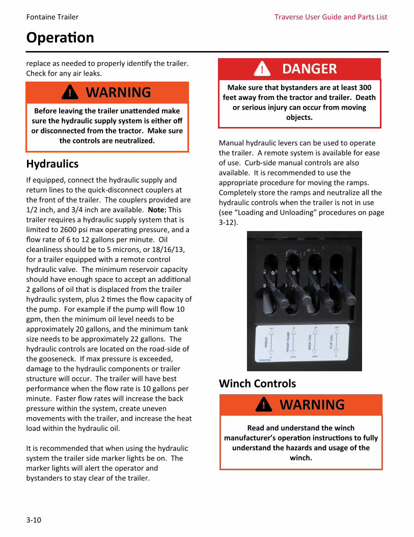
Hydraulics If equipped, connect the hydraulic supply and return lines to the quick-disconnect couplers at the front of the trailer. The couplers provided are 1/2 inch, and 3/4 inch are available. Note: This trailer requires a hydraulic supply system that is limited to 2600 psi max operating pressure, and a flow rate of 6 to 12 gallons per minute. Oil cleanliness should be to 5 microns, or 18/16/13, for a trailer equipped with a remote control hydraulic valve. The minimum reservoir capacity should have enough space to accept an additional 2 gallons of oil that is displaced from the trailer hydraulic system, plus 2 times the flow capacity of the pump. For example if the pump will flow 10 gpm, then the minimum oil level needs to be approximately 20 gallons, and the minimum tank size needs to be approximately 22 gallons. The hydraulic controls are located on the road-side of the gooseneck. If max pressure is exceeded, damage to the hydraulic components or trailer structure will occur. The trailer will have best performance when the flow rate is 10 gallons per minute. Faster flow rates will increase the back pressure within the system, create uneven movements with the trailer, and increase the heat load within the hydraulic oil. It is recommended that when using the hydraulic system the trailer side marker lights be on. The marker lights will alert the operator and bystanders to stay clear of the trailer.
Manual hydraulic levers can be used to operate the trailer. A remote system is available for ease of use. Curb-side manual controls are also available. It is recommended to use the appropriate procedure for moving the ramps. Completely store the ramps and neutralize all the hydraulic controls when the trailer is not in use (see “Loading and Unloading” procedures on page 3-12).
Winch Controls
Read and understand the winch manufacturer’s operation instructions to fully
understand the hazards and usage of the winch.
Before leaving the trailer unattended make sure the hydraulic supply system is either off or disconnected from the tractor. Make sure
the controls are neutralized.
Make sure that bystanders are at least 300 feet away from the tractor and trailer. Death
or serious injury can occur from moving objects.
Fontaine Trailer Traverse User Guide and Parts List
3-11
Do not side load or side drag items to the trailer. There are no outrigger supports and the winch is set up for pulling in line along the length of the trailer from the rear. Do not drag the cable against the deck. The winch control is the hydraulic lever on the left side of the valve located on the road-side of the gooseneck. There are three positions to this lever, and it is spring centered for the neutral position. Pushing up on the lever will unspool the cable. Pushing down on the lever will spool in the cable.
Additional winch controls are located on the road-side of the gooseneck next to the hydraulic valve. Some winches are available with a 2-speed control. By turning on the switch, the winch will operate at a faster speed but with reduced power. There is also a manual clutch that can be released to freespool the cable. Depressing the detent latch and turning the clutch lever as indicated on the winch label will freespool the cable. An optional air clutch is available. For this, pull out on the control knob to release the clutch, and push in to engage it.
Front Ramp Lever The front ramp hydraulic control is the second lever in the hydraulic valve next to the winch. The controls are labeled on the decal below the valve levers. There are three positions to the lever, and it is spring centered for the off position. Pushing up on the lever will raise the front ramp. The ramp has a load capacity of 10K lbs. In the fully raised position it will be supported by the gravity lock on the rear of the gooseneck. See the “Loading/Unloading Procedure” section for additional detail regarding the gravity lock. Pushing down on the lever will lower the ramp. The gravity lock must be released to lower the ramp from the fully raised position. The hydraulic valve for this ramp contains a down pressure control to help regulate the speed and hydraulic power in the lowering position.
Always leave at least one layer (five wraps) of cable on the winch spool for proper
performance and to ensure the cable does not detach. Death or serious injury can
Operation
Do not handle the cable when the winch is on. The cable can cut you or catch and pull you
into the spool causing serious injury. 3
It is important that the winch is not used to side load the trailer or side drag items to the trailer. This will cause damage to the trailer
and a roll over condition. Death, serious injury, and property damage will result.
Care must be given when un-spooling the cable to not “nest,” or bunch up, the cable
around the winch. Ensure there is some tension in the cable.
Never attempt to freespool the winch cable when the cable is under load. Loss of load
control can result in death, serious injury or damage to equipment.
Crush Hazard. When moving the front hydraulic ramp, keep away from the trailer
frame and front ramp.
Fontaine Trailer Traverse User Guide and Parts List
3-12
Operation
Main Tail Lever The main hydraulic tail lift cylinders are controlled by the third lever in the hydraulic valve. There are three positions to the lever, and it is spring centered for the off position. Pushing up on the lever will raise the tail assembly. The tail has a lift capacity of 25K lbs. Be mindful of legal axle loads when positioning payload for travel. To fully lower the ramp, the tail lock must be released. Pushing down on the lever will lower the ramp. The valve for this tail contains a down pressure control to reduce hydraulic power when making contact with the ground or any object.
Flip Tail Lever The small hydraulic flip tail is controlled by the last lever to the right side of the hydraulic valve. There are three positions to the lever, and it is spring centered for the off position. To move the tail from the closed position the lock must be released. Pushing up on the lever will rotate the flip tail out. Pushing down on the lever will rotate the flip tail in.
Loading/Unloading Procedure
Read and understand all procedures for parking and hydraulic system operation previously mentioned. Make sure the area around the tractor and trailer is clear and free from foreign objects and bystanders are at least 300 feet away. Park the tractor in a straight line with the trailer on level ground that can support the tractor and trailer. Put the transmission in neutral, and set the park brakes on both the tractor and trailer. Pull out the suspension dump valve on the side of the gooseneck. This will help to provide a stable and low ramp. Inspect any load on the trailer deck for proper securement.
Start the hydraulic power system. If the winch cable is connected to the ramps, it will need to be disconnected, or the cable will need to be spooled in or out from the winch accordingly while positioning the ramps to keep proper tension on the cable and prevent the load from shifting. If any load is secured to more than one ramp or deck platform, the load securement will need to be changed to allow the two platforms to move separately. Push the control for the Main Tail up, and hold the lever until the tail ramp assembly of the trailer is all the way raised. Pull out the air control knobs
This trailer must be hitched to a truck tractor with the landing gear raised.
Do not position yourself near the ramp assembly when moving the ramps. A
hydraulic failure could result in the ramps falling down.
By tilting the trailer ramps, the winch cable will change tension. Do not connect the cable to the ramps while tilting. This can also cause
the load to be moved.
Crush Hazard. When moving the hydraulic tail ramp assembly, keep away from the trailer
frame.
Fontaine Trailer Traverse User Guide and Parts List
3-13
Operation
3 3
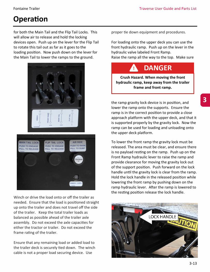
for both the Main Tail and the Flip Tail Locks. This will allow air to release and hold the locking devices open. Push up on the lever for the Flip Tail to rotate this tail out as far as it goes to the loading position. Now push down on the lever for the Main Tail to lower the ramps to the ground.
Winch or drive the load onto or off the trailer as needed. Ensure that the load is positioned straight up onto the trailer and does not travel off the side of the trailer. Keep the total trailer loads as balanced as possible ahead of the trailer axle assembly. Do not exceed the axle capacities for either the tractor or trailer. Do not exceed the frame rating of the trailer. Ensure that any remaining load or added load to the trailer deck is securely tied down. The winch cable is not a proper load securing device. Use
proper tie down equipment and procedures. For loading onto the upper deck you can use the front hydraulic ramp. Push up on the lever in the hydraulic valve labeled Front Ramp. Raise the ramp all the way to the top. Make sure
the ramp gravity lock device is in position, and lower the ramp onto the supports. Ensure the ramp is in the correct position to provide a close approach platform with the upper deck, and that it is supported properly by the gravity lock. Now the ramp can be used for loading and unloading onto the upper deck platform.
To lower the front ramp the gravity lock must be released. The area must be clear, and ensure there is no payload resting on the ramp. Push up on the Front Ramp hydraulic lever to raise the ramp and provide clearance for moving the gravity lock out of the support position. Push forward on the lock handle until the gravity lock is clear from the ramp. Hold the lock handle in the released position while lowering the front ramp by pushing down on the ramp hydraulic lever. After the ramp is lowered to the resting position release the lock handle.
Crush Hazard. When moving the front hydraulic ramp, keep away from the trailer
frame and front ramp.
Fontaine Trailer Traverse User Guide and Parts List
3-14
Operation
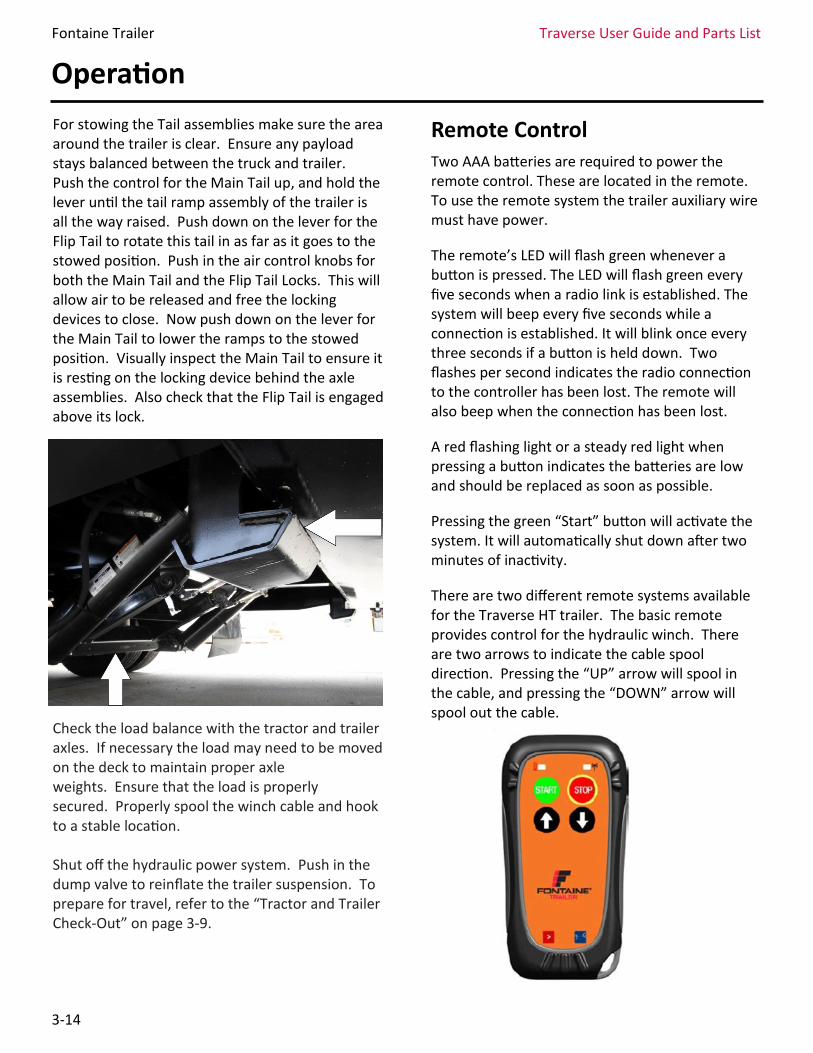
For stowing the Tail assemblies make sure the area around the trailer is clear. Ensure any payload stays balanced between the truck and trailer. Push the control for the Main Tail up, and hold the lever until the tail ramp assembly of the trailer is all the way raised. Push down on the lever for the Flip Tail to rotate this tail in as far as it goes to the stowed position. Push in the air control knobs for both the Main Tail and the Flip Tail Locks. This will allow air to be released and free the locking devices to close. Now push down on the lever for the Main Tail to lower the ramps to the stowed position. Visually inspect the Main Tail to ensure it is resting on the locking device behind the axle assemblies. Also check that the Flip Tail is engaged above its lock.
Check the load balance with the tractor and trailer axles. If necessary the load may need to be moved on the deck to maintain proper axle weights. Ensure that the load is properly secured. Properly spool the winch cable and hook to a stable location. Shut off the hydraulic power system. Push in the dump valve to reinflate the trailer suspension. To prepare for travel, refer to the “Tractor and Trailer Check-Out” on page 3-9.
Remote Control Two AAA batteries are required to power the remote control. These are located in the remote. To use the remote system the trailer auxiliary wire must have power.
The remote’s LED will flash green whenever a button is pressed. The LED will flash green every five seconds when a radio link is established. The system will beep every five seconds while a connection is established. It will blink once every three seconds if a button is held down. Two flashes per second indicates the radio connection to the controller has been lost. The remote will also beep when the connection has been lost.
A red flashing light or a steady red light when pressing a button indicates the batteries are low and should be replaced as soon as possible.
Pressing the green “Start” button will activate the system. It will automatically shut down after two minutes of inactivity.
There are two different remote systems available for the Traverse HT trailer. The basic remote provides control for the hydraulic winch. There are two arrows to indicate the cable spool direction. Pressing the “UP” arrow will spool in the cable, and pressing the “DOWN” arrow will spool out the cable.
Fontaine Trailer Traverse User Guide and Parts List
3-15
Operation
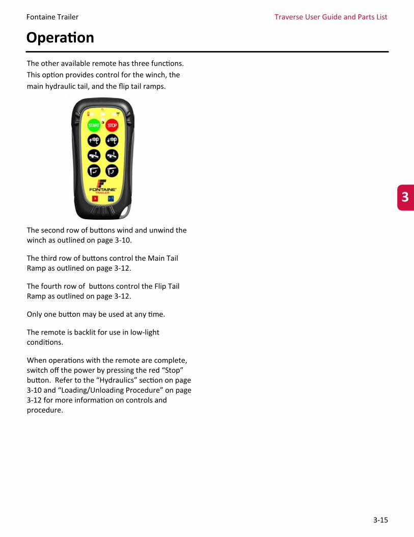
The other available remote has three functions.
This option provides control for the winch, the
main hydraulic tail, and the flip tail ramps.
The second row of buttons wind and unwind the winch as outlined on page 3-10.
The third row of buttons control the Main Tail Ramp as outlined on page 3-12.
The fourth row of buttons control the Flip Tail Ramp as outlined on page 3-12.
Only one button may be used at any time.
The remote is backlit for use in low-light conditions.
When operations with the remote are complete, switch off the power by pressing the red “Stop” button. Refer to the “Hydraulics” section on page 3-10 and “Loading/Unloading Procedure” on page 3-12 for more information on controls and procedure.
3