Hydraulic System Fundamentals
37
PowerPoint ® Presentation Chapter 3 Hydraulic System Fundamentals Hydraulic Principles • Hydraulic System Pressure Supplements • Hydraulic Means of Transmission • Fluid Power System Diagrams
-
Upload
mohammed-al-odat -
Category
Documents
-
view
223 -
download
0
Transcript of Hydraulic System Fundamentals
7/28/2019 Hydraulic System Fundamentals
http://slidepdf.com/reader/full/hydraulic-system-fundamentals 1/37
PowerPoint ® Presentation
Chapter 3
Hydraulic System Fundamentals
Hydraulic Principles • HydraulicSystem Pressure Supplements •
Hydraulic Means of Transmission •
Fluid Power System Diagrams
7/28/2019 Hydraulic System Fundamentals
http://slidepdf.com/reader/full/hydraulic-system-fundamentals 2/37
Chapter 3 — Hydraulic System Fundamentals
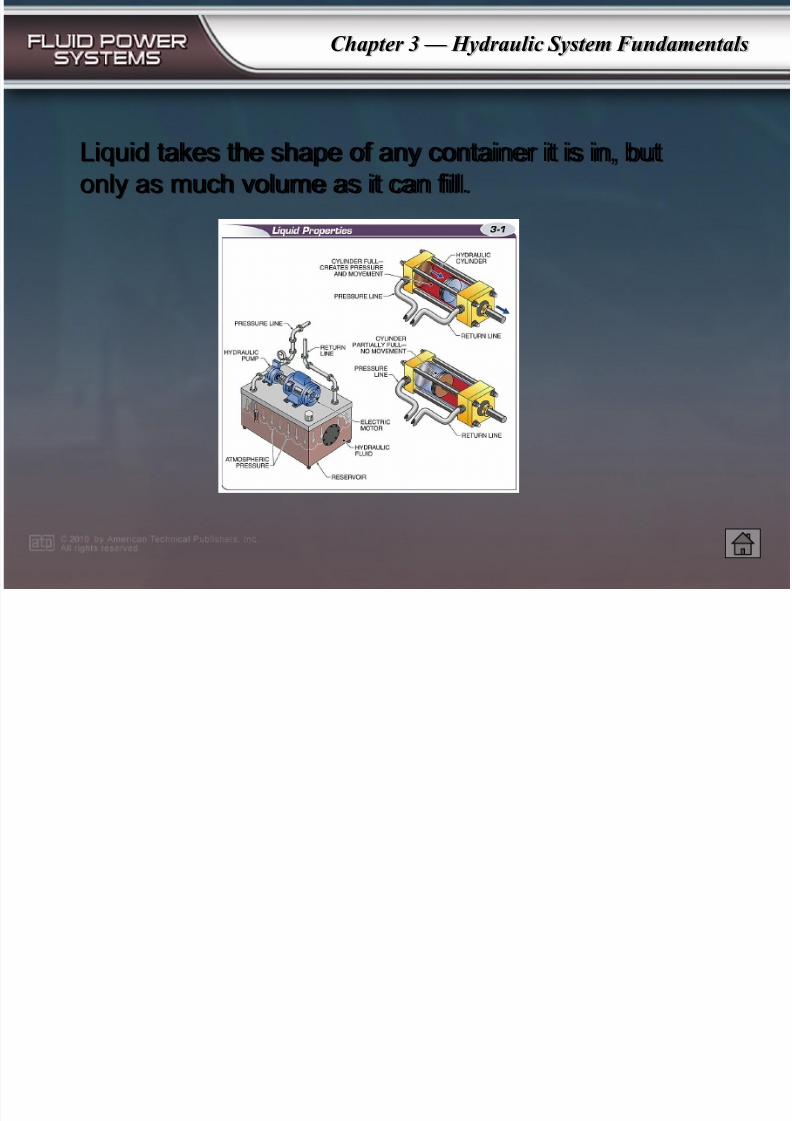
Liquid takes the shape of any container it is in, but
only as much volume as it can fill.
7/28/2019 Hydraulic System Fundamentals
http://slidepdf.com/reader/full/hydraulic-system-fundamentals 3/37
Chapter 3 — Hydraulic System Fundamentals
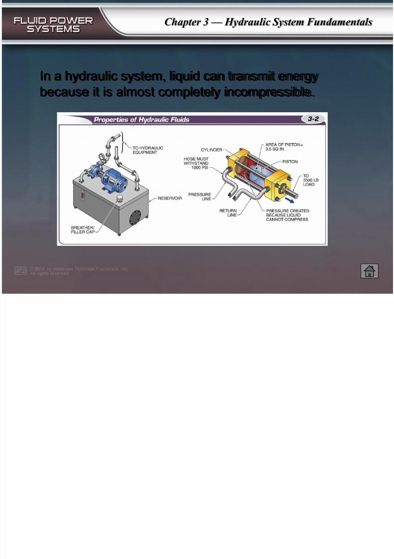
In a hydraulic system, liquid can transmit energy
because it is almost completely incompressible.
7/28/2019 Hydraulic System Fundamentals
http://slidepdf.com/reader/full/hydraulic-system-fundamentals 4/37
Chapter 3 — Hydraulic System Fundamentals
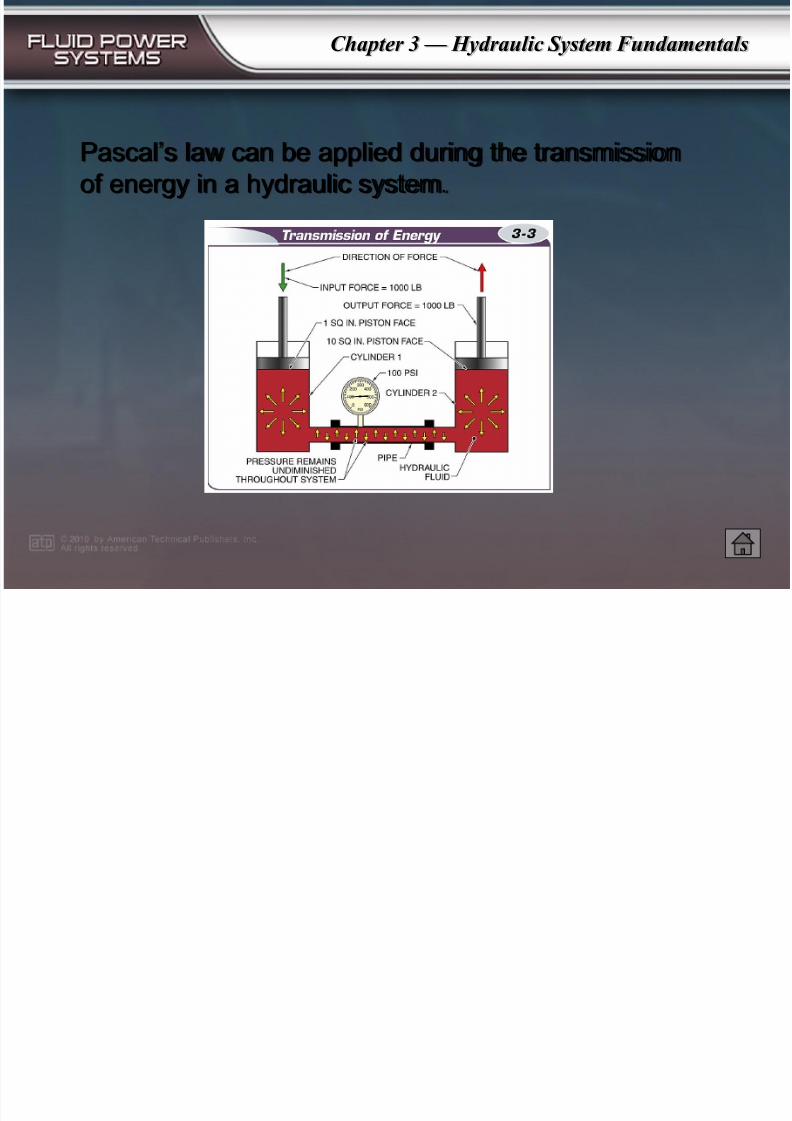
Pascal’s law can be applied during the transmission
of energy in a hydraulic system.
7/28/2019 Hydraulic System Fundamentals
http://slidepdf.com/reader/full/hydraulic-system-fundamentals 5/37
Chapter 3 — Hydraulic System Fundamentals
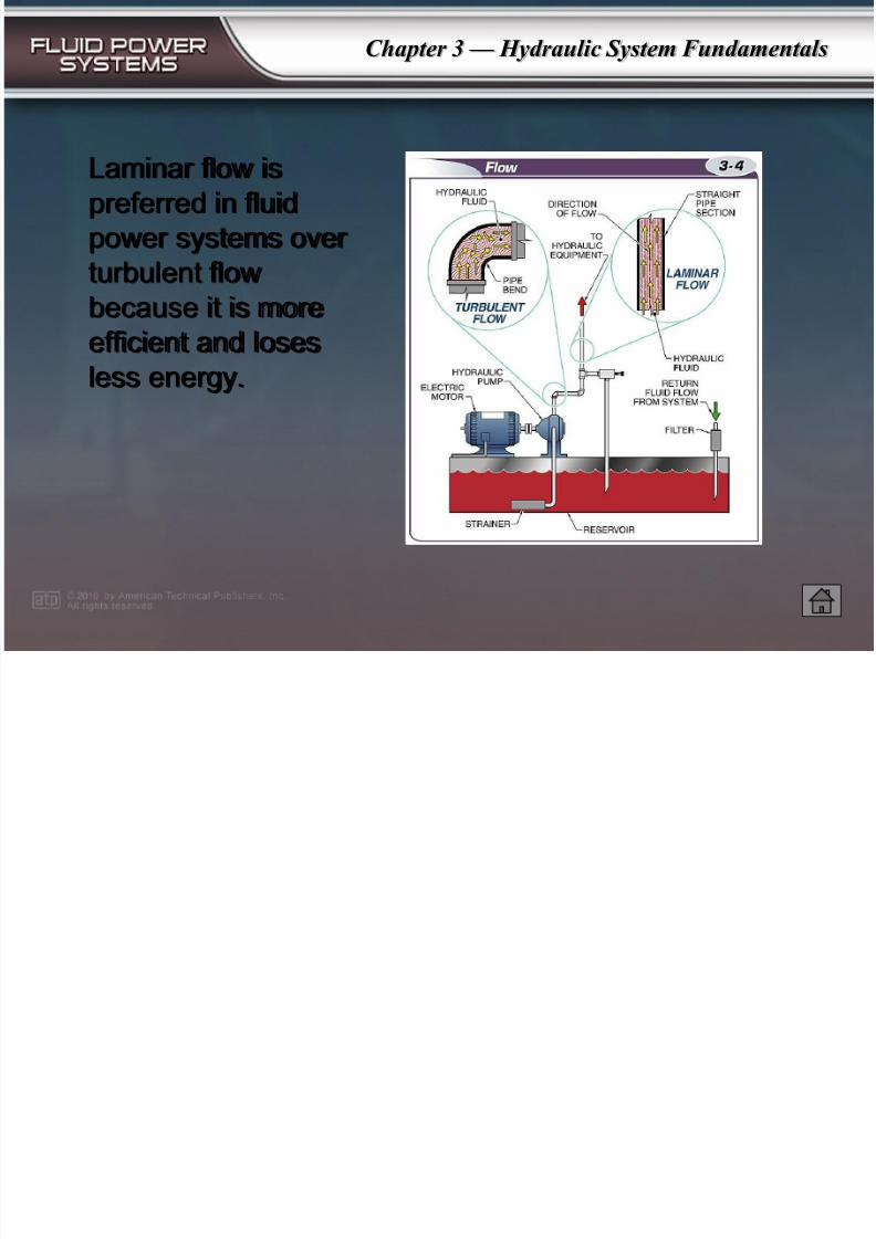
Laminar flow is
preferred in fluid
power systems over
turbulent flow
because it is moreefficient and loses
less energy.
7/28/2019 Hydraulic System Fundamentals
http://slidepdf.com/reader/full/hydraulic-system-fundamentals 6/37
Chapter 3 — Hydraulic System Fundamentals
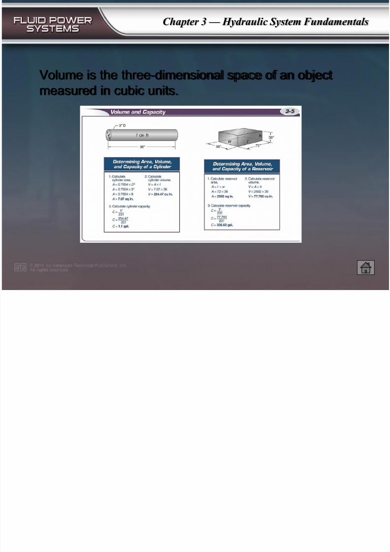
Volume is the three-dimensional space of an object
measured in cubic units.
7/28/2019 Hydraulic System Fundamentals
http://slidepdf.com/reader/full/hydraulic-system-fundamentals 7/37
Chapter 3 — Hydraulic System Fundamentals
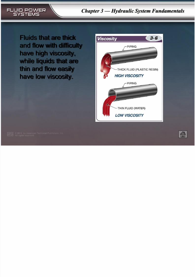
Fluids that are thick
and flow with difficulty
have high viscosity,
while liquids that are
thin and flow easilyhave low viscosity.
7/28/2019 Hydraulic System Fundamentals
http://slidepdf.com/reader/full/hydraulic-system-fundamentals 8/37
Chapter 3 — Hydraulic System Fundamentals
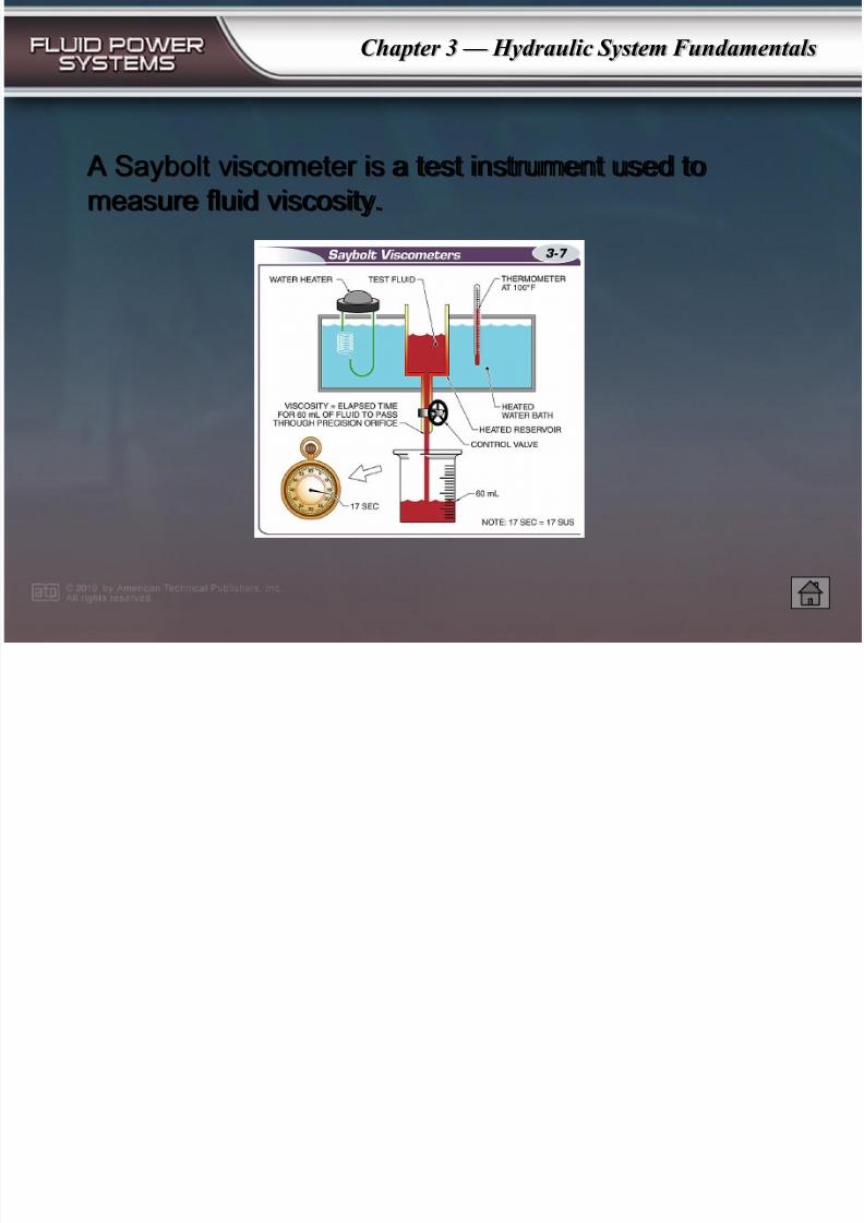
A Saybolt viscometer is a test instrument used to
measure fluid viscosity.
7/28/2019 Hydraulic System Fundamentals
http://slidepdf.com/reader/full/hydraulic-system-fundamentals 9/37
Chapter 3 — Hydraulic System Fundamentals
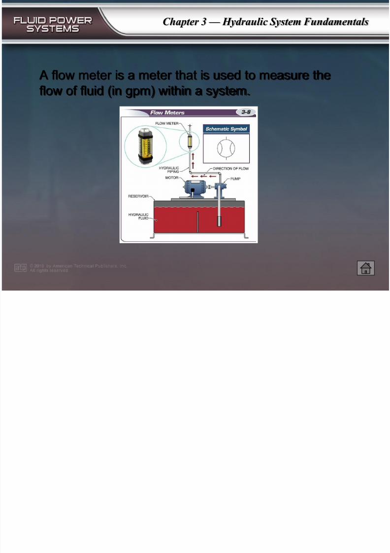
A flow meter is a meter that is used to measure the
flow of fluid (in gpm) within a system.
7/28/2019 Hydraulic System Fundamentals
http://slidepdf.com/reader/full/hydraulic-system-fundamentals 10/37
Chapter 3 — Hydraulic System Fundamentals
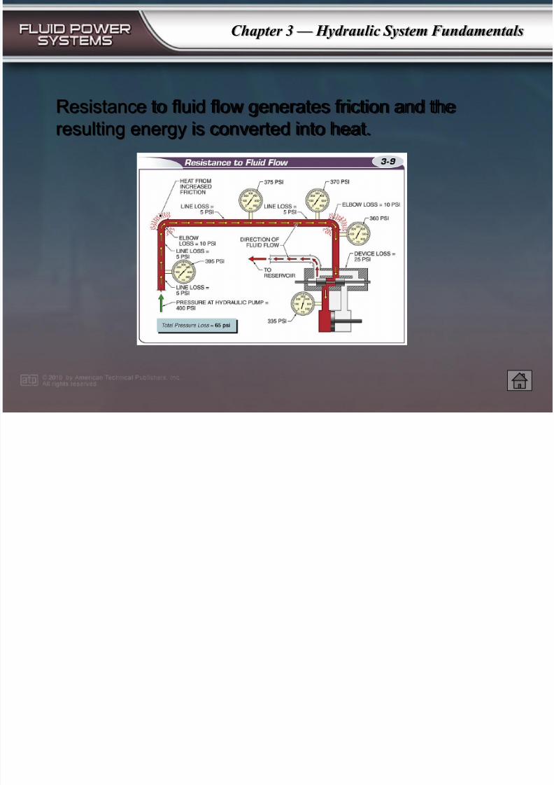
Resistance to fluid flow generates friction and the
resulting energy is converted into heat.
7/28/2019 Hydraulic System Fundamentals
http://slidepdf.com/reader/full/hydraulic-system-fundamentals 11/37
Chapter 3 — Hydraulic System Fundamentals
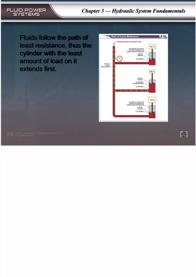
Fluids follow the path of
least resistance, thus the
cylinder with the least
amount of load on it
extends first.
7/28/2019 Hydraulic System Fundamentals
http://slidepdf.com/reader/full/hydraulic-system-fundamentals 12/37
Chapter 3 — Hydraulic System Fundamentals
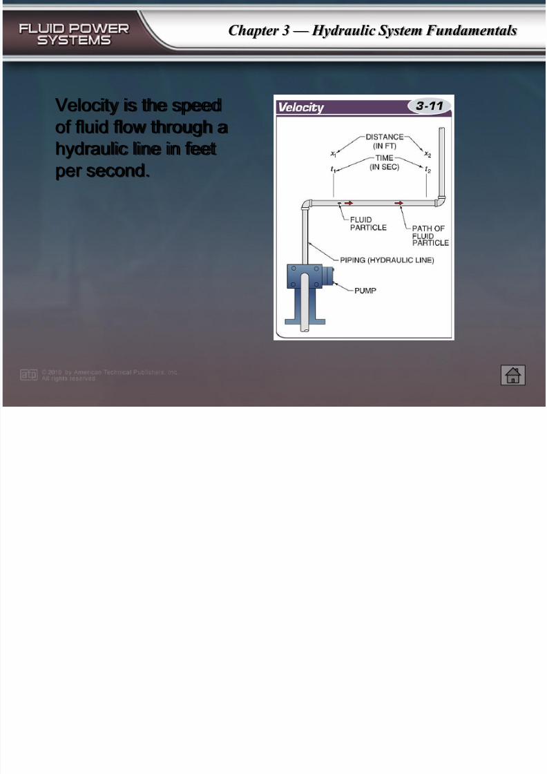
Velocity is the speed
of fluid flow through a
hydraulic line in feet
per second.
7/28/2019 Hydraulic System Fundamentals
http://slidepdf.com/reader/full/hydraulic-system-fundamentals 13/37
Chapter 3 — Hydraulic System Fundamentals
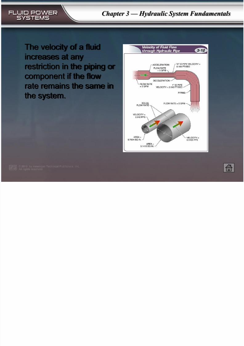
The velocity of a fluid
increases at any
restriction in the piping or
component if the flow
rate remains the same inthe system.
7/28/2019 Hydraulic System Fundamentals
http://slidepdf.com/reader/full/hydraulic-system-fundamentals 14/37
Chapter 3 — Hydraulic System Fundamentals
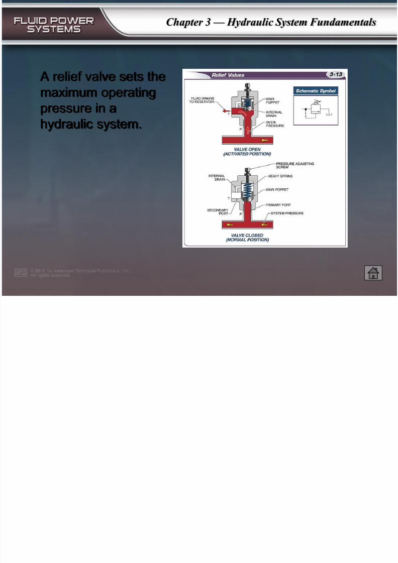
A relief valve sets the
maximum operating
pressure in a
hydraulic system.
7/28/2019 Hydraulic System Fundamentals
http://slidepdf.com/reader/full/hydraulic-system-fundamentals 15/37
Chapter 3 — Hydraulic System Fundamentals
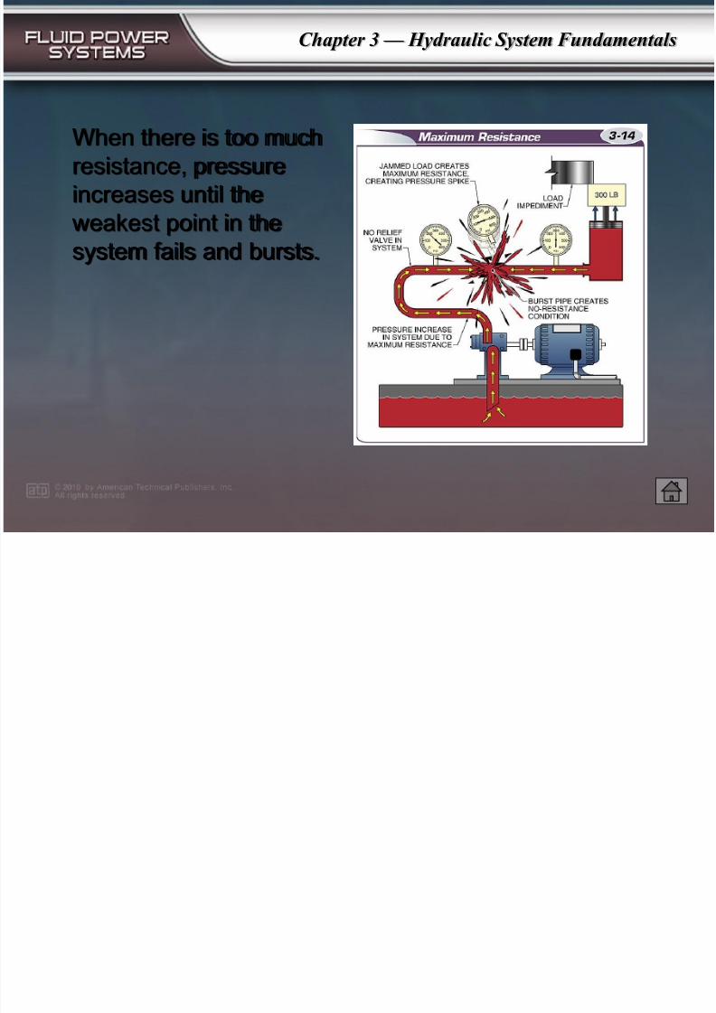
When there is too much
resistance, pressure
increases until the
weakest point in the
system fails and bursts.
7/28/2019 Hydraulic System Fundamentals
http://slidepdf.com/reader/full/hydraulic-system-fundamentals 16/37
Chapter 3 — Hydraulic System Fundamentals
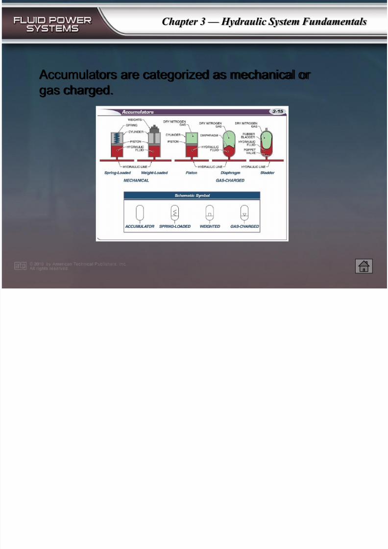
Accumulators are categorized as mechanical or
gas charged.
7/28/2019 Hydraulic System Fundamentals
http://slidepdf.com/reader/full/hydraulic-system-fundamentals 17/37
Chapter 3 — Hydraulic System Fundamentals
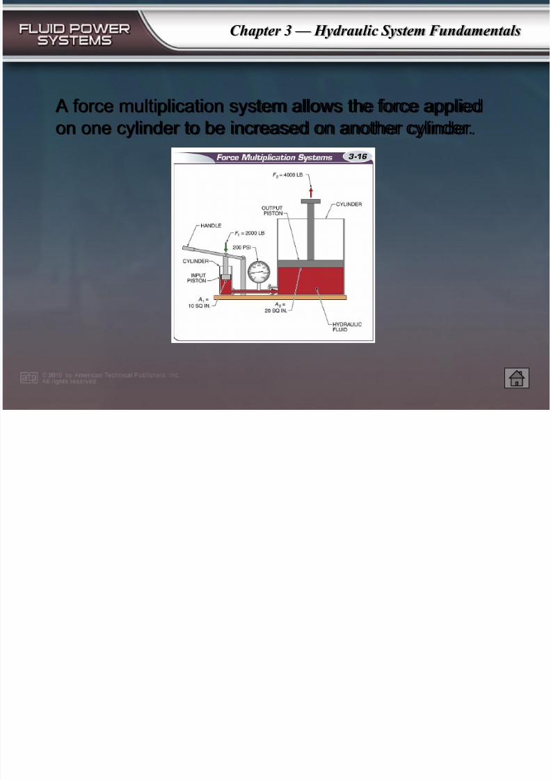
A force multiplication system allows the force applied
on one cylinder to be increased on another cylinder.
7/28/2019 Hydraulic System Fundamentals
http://slidepdf.com/reader/full/hydraulic-system-fundamentals 18/37
Chapter 3 — Hydraulic System Fundamentals
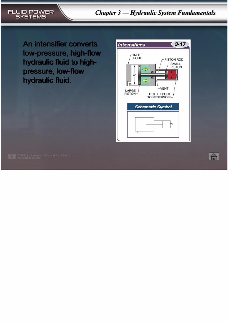
An intensifier converts
low-pressure, high-flow
hydraulic fluid to high-
pressure, low-flow
hydraulic fluid.
7/28/2019 Hydraulic System Fundamentals
http://slidepdf.com/reader/full/hydraulic-system-fundamentals 19/37
Chapter 3 — Hydraulic System Fundamentals
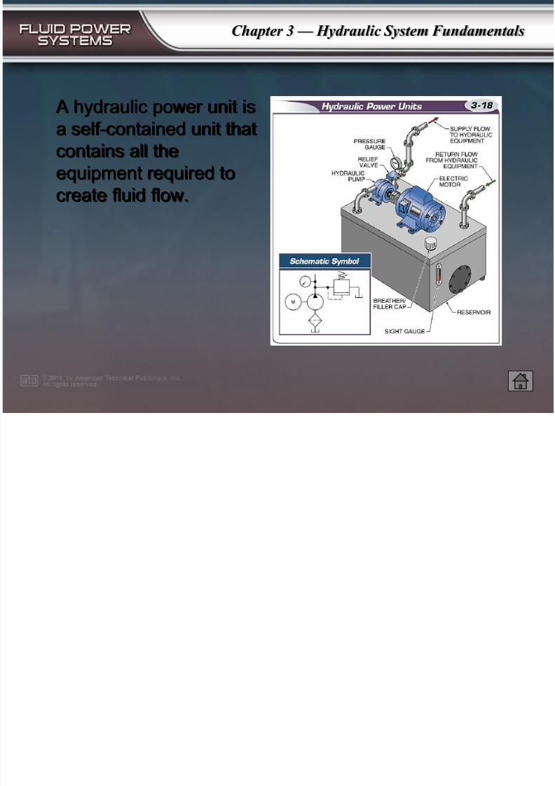
A hydraulic power unit is
a self-contained unit that
contains all the
equipment required to
create fluid flow.
7/28/2019 Hydraulic System Fundamentals
http://slidepdf.com/reader/full/hydraulic-system-fundamentals 20/37
Chapter 3 — Hydraulic System Fundamentals
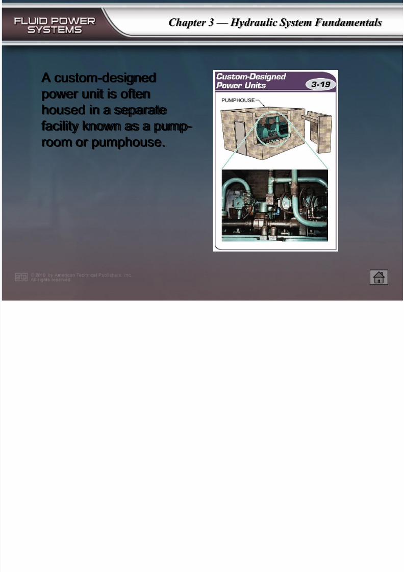
A custom-designed
power unit is often
housed in a separate
facility known as a pump-
room or pumphouse.
7/28/2019 Hydraulic System Fundamentals
http://slidepdf.com/reader/full/hydraulic-system-fundamentals 21/37
Chapter 3 — Hydraulic System Fundamentals
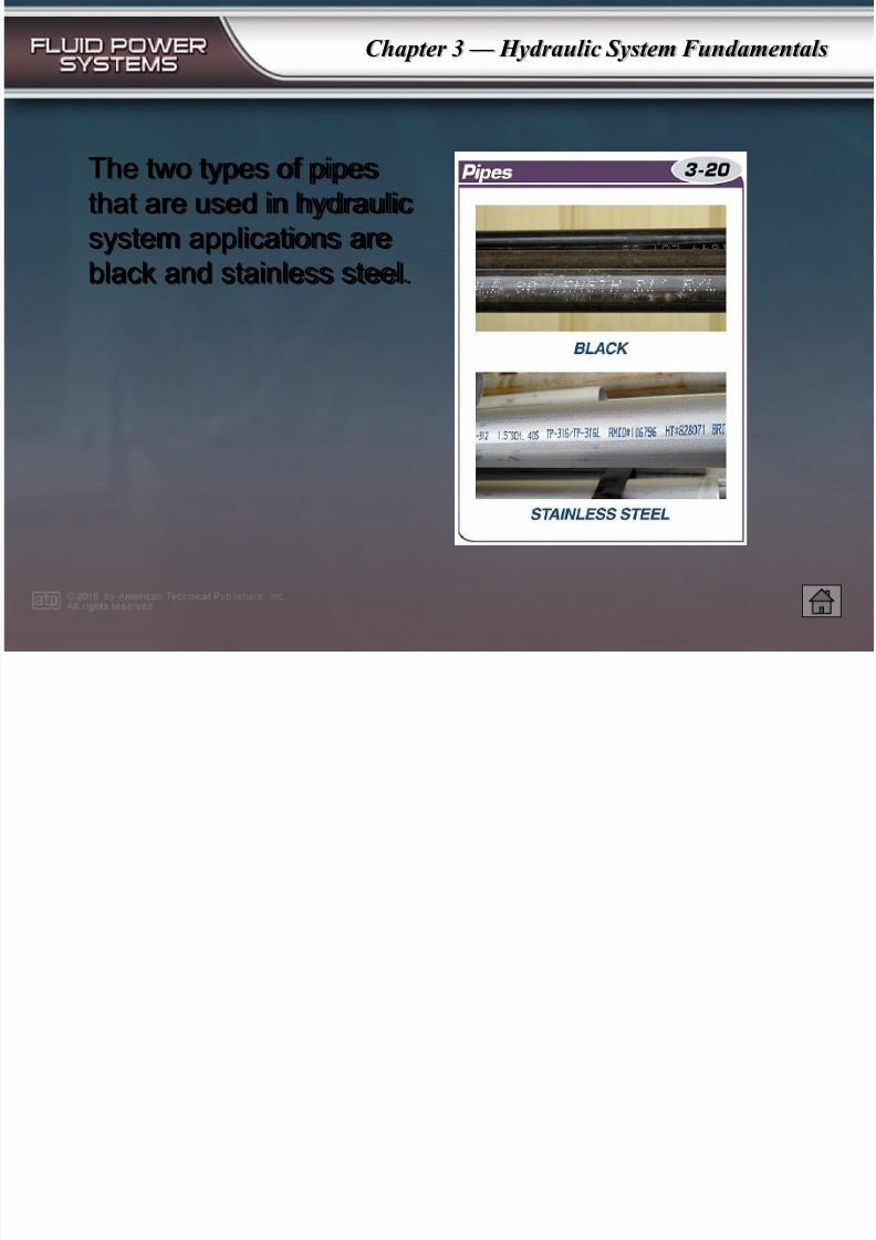
The two types of pipes
that are used in hydraulic
system applications are
black and stainless steel.
7/28/2019 Hydraulic System Fundamentals
http://slidepdf.com/reader/full/hydraulic-system-fundamentals 22/37
Chapter 3 — Hydraulic System Fundamentals
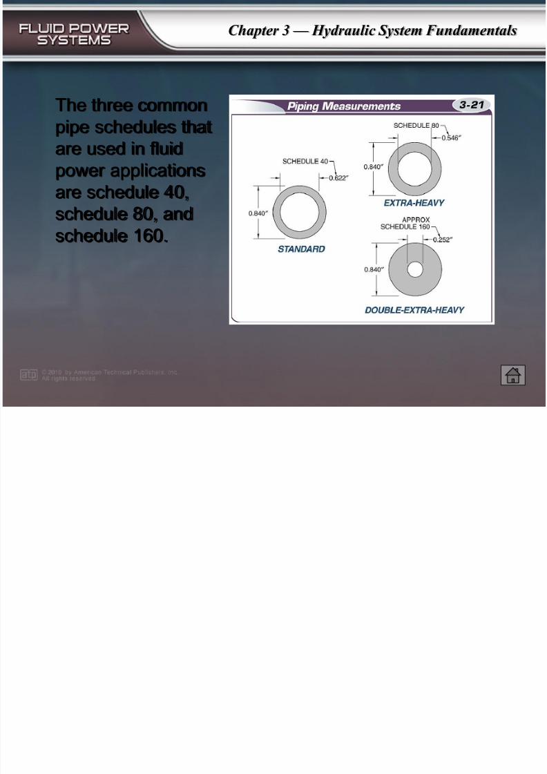
The three common
pipe schedules that
are used in fluid
power applications
are schedule 40,schedule 80, and
schedule 160.
7/28/2019 Hydraulic System Fundamentals
http://slidepdf.com/reader/full/hydraulic-system-fundamentals 23/37
Chapter 3 — Hydraulic System Fundamentals
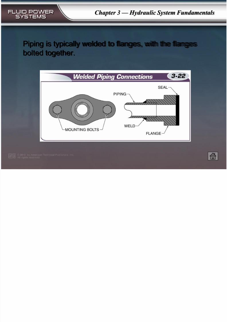
Piping is typically welded to flanges, with the flanges
bolted together.
7/28/2019 Hydraulic System Fundamentals
http://slidepdf.com/reader/full/hydraulic-system-fundamentals 24/37
Chapter 3 — Hydraulic System Fundamentals
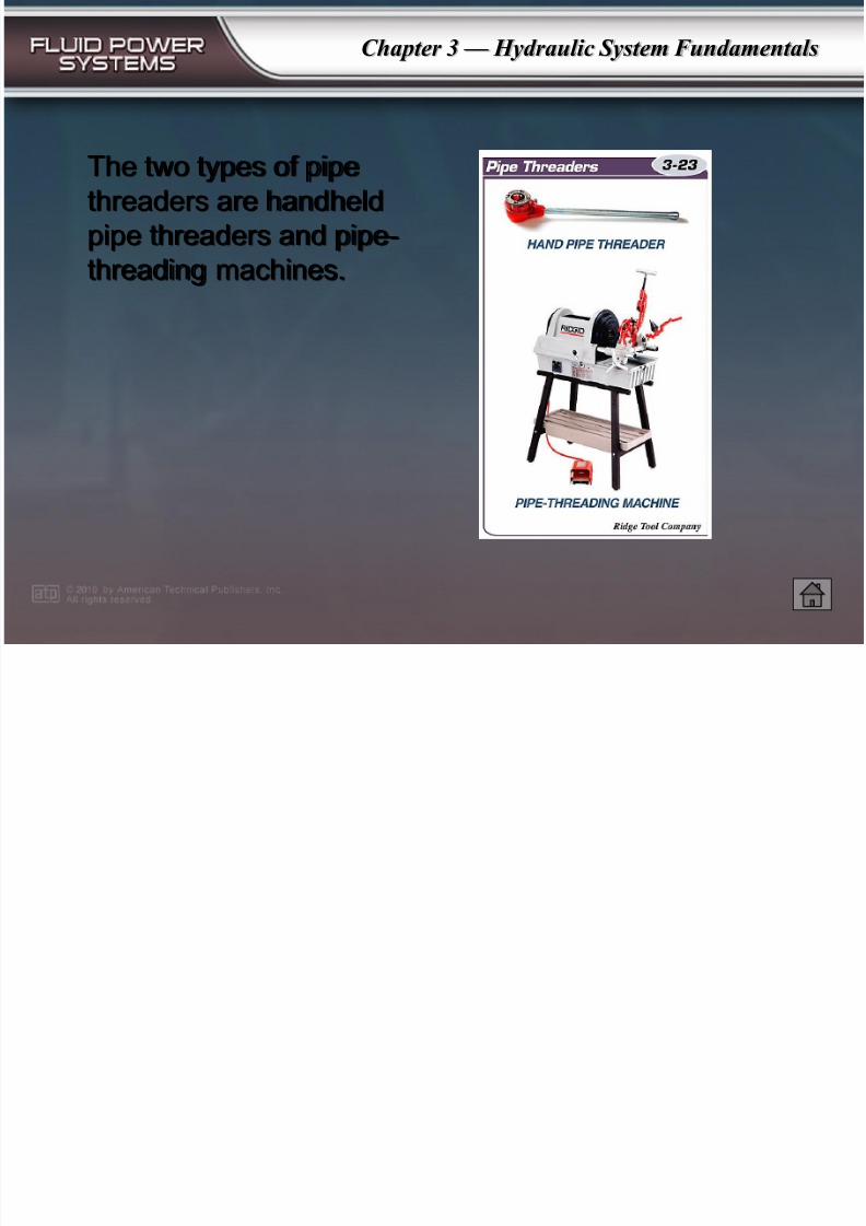
The two types of pipe
threaders are handheld
pipe threaders and pipe-
threading machines.
7/28/2019 Hydraulic System Fundamentals
http://slidepdf.com/reader/full/hydraulic-system-fundamentals 25/37
Chapter 3 — Hydraulic System Fundamentals
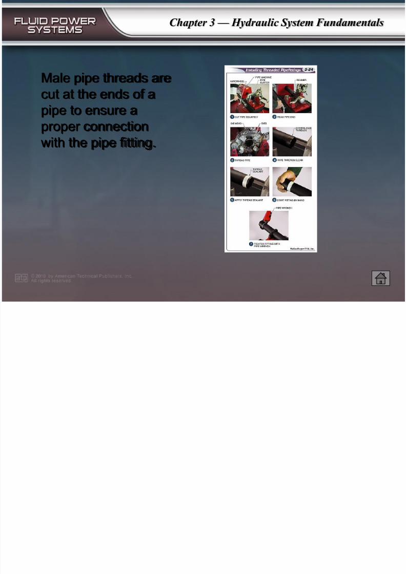
Male pipe threads are
cut at the ends of a
pipe to ensure a
proper connection
with the pipe fitting.
7/28/2019 Hydraulic System Fundamentals
http://slidepdf.com/reader/full/hydraulic-system-fundamentals 26/37
Chapter 3 — Hydraulic System Fundamentals
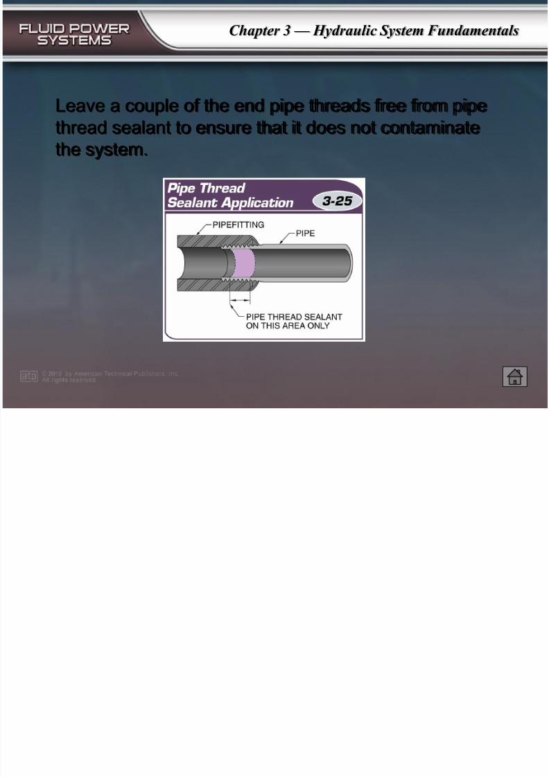
Leave a couple of the end pipe threads free from pipe
thread sealant to ensure that it does not contaminate
the system.
7/28/2019 Hydraulic System Fundamentals
http://slidepdf.com/reader/full/hydraulic-system-fundamentals 27/37
Chapter 3 — Hydraulic System Fundamentals
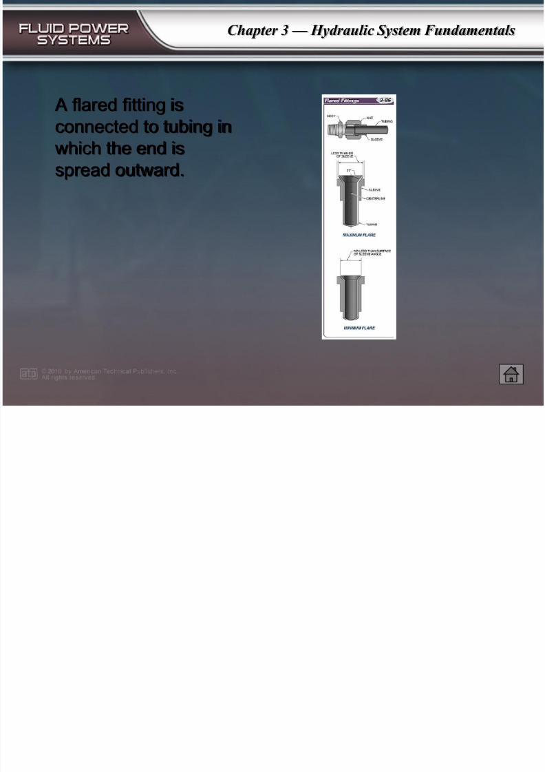
A flared fitting is
connected to tubing in
which the end is
spread outward.
7/28/2019 Hydraulic System Fundamentals
http://slidepdf.com/reader/full/hydraulic-system-fundamentals 28/37
Chapter 3 — Hydraulic System Fundamentals
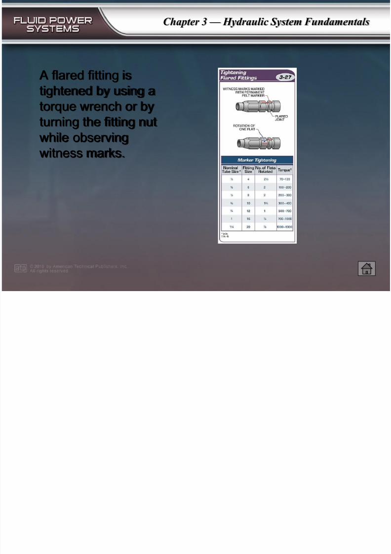
A flared fitting is
tightened by using a
torque wrench or by
turning the fitting nut
while observingwitness marks.
7/28/2019 Hydraulic System Fundamentals
http://slidepdf.com/reader/full/hydraulic-system-fundamentals 29/37
Chapter 3 — Hydraulic System Fundamentals
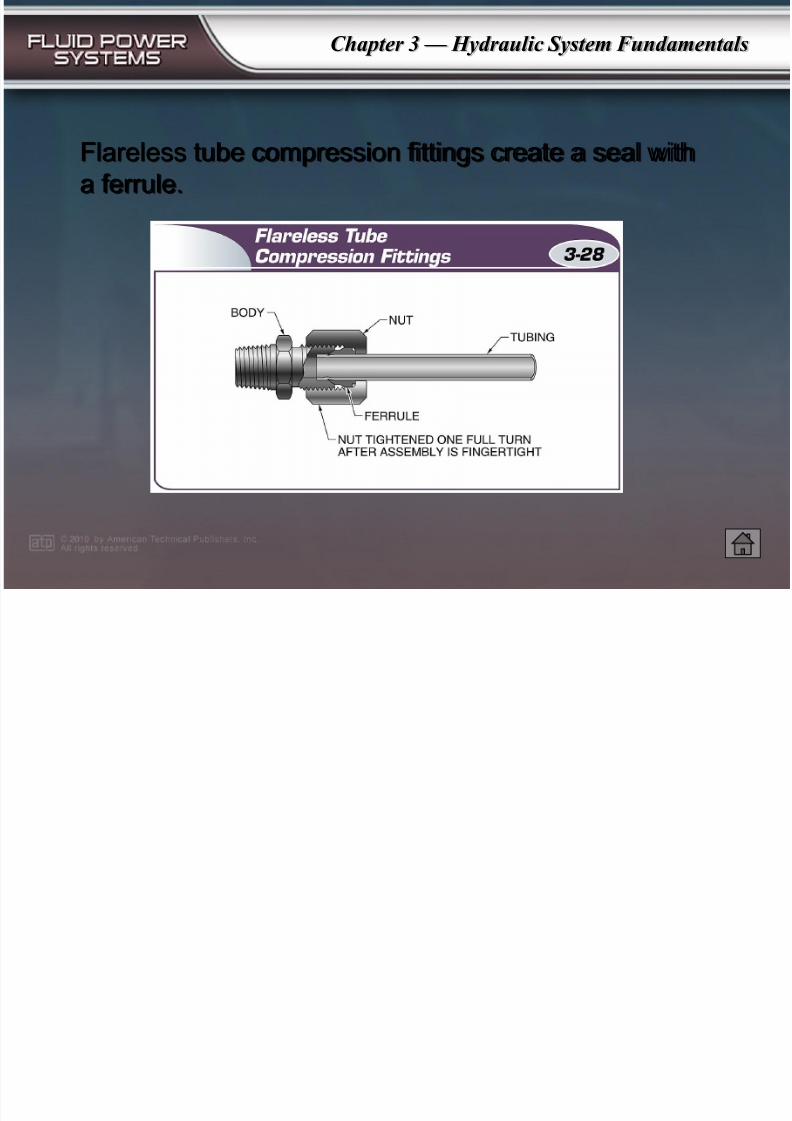
Flareless tube compression fittings create a seal witha ferrule.
7/28/2019 Hydraulic System Fundamentals
http://slidepdf.com/reader/full/hydraulic-system-fundamentals 30/37
Chapter 3 — Hydraulic System Fundamentals
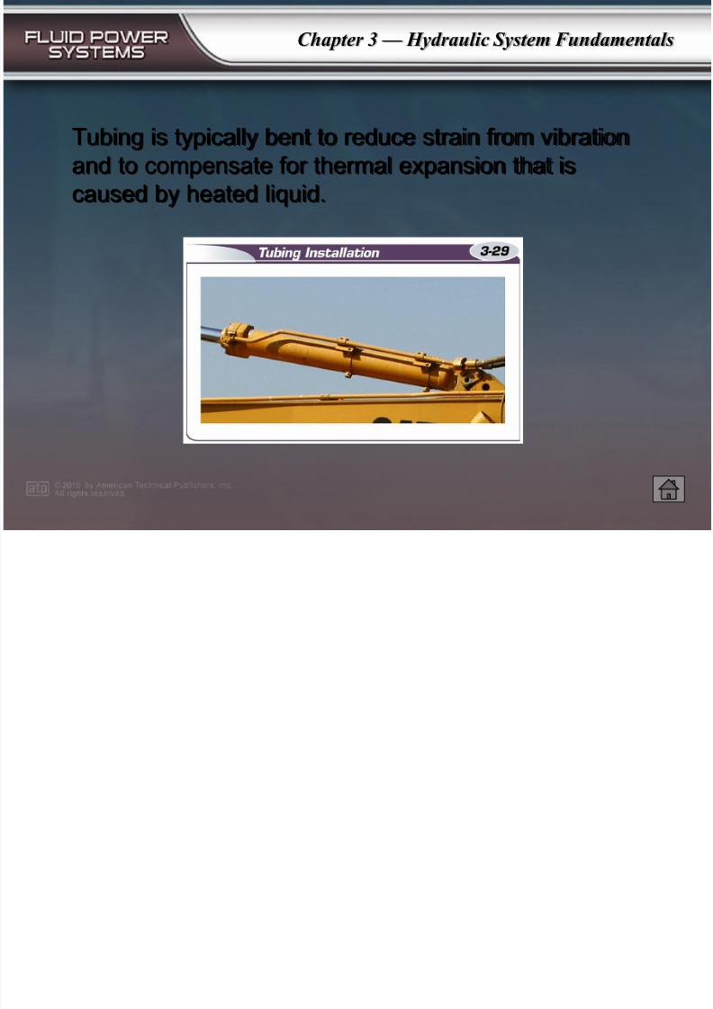
Tubing is typically bent to reduce strain from vibrationand to compensate for thermal expansion that is
caused by heated liquid.
7/28/2019 Hydraulic System Fundamentals
http://slidepdf.com/reader/full/hydraulic-system-fundamentals 31/37
Chapter 3 — Hydraulic System Fundamentals
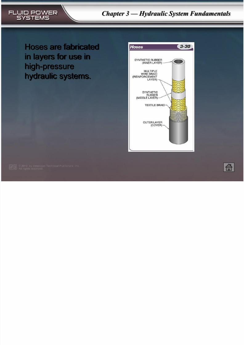
Hoses are fabricatedin layers for use in
high-pressure
hydraulic systems.
7/28/2019 Hydraulic System Fundamentals
http://slidepdf.com/reader/full/hydraulic-system-fundamentals 32/37
Chapter 3 — Hydraulic System Fundamentals
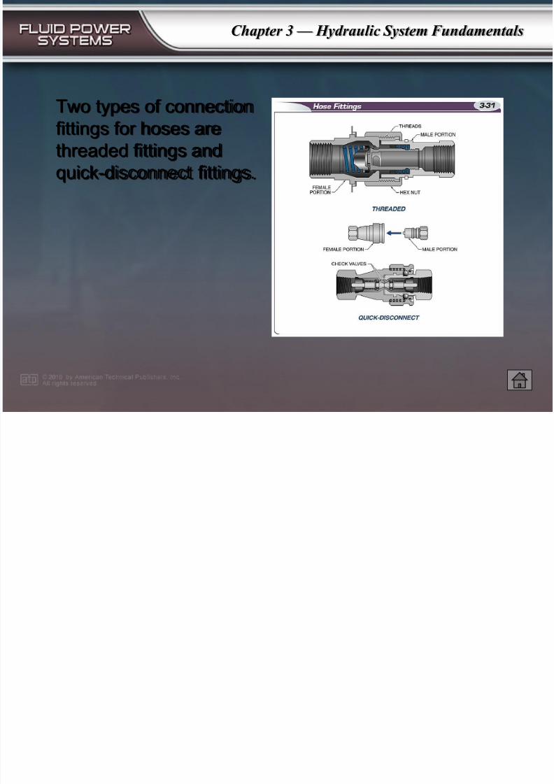
Two types of connectionfittings for hoses are
threaded fittings and
quick-disconnect fittings.
7/28/2019 Hydraulic System Fundamentals
http://slidepdf.com/reader/full/hydraulic-system-fundamentals 33/37
Chapter 3 — Hydraulic System Fundamentals
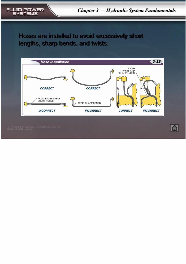
Hoses are installed to avoid excessively shortlengths, sharp bends, and twists.
7/28/2019 Hydraulic System Fundamentals
http://slidepdf.com/reader/full/hydraulic-system-fundamentals 34/37
Chapter 3 — Hydraulic System Fundamentals
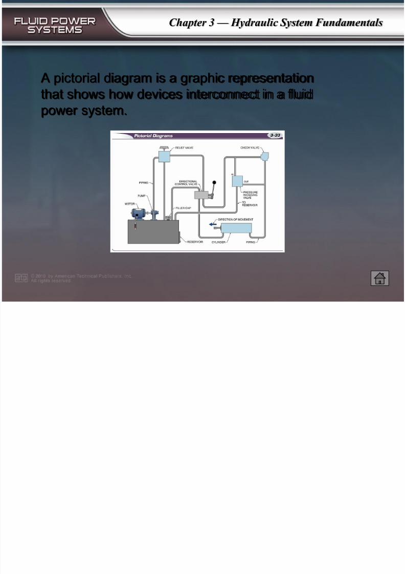
A pictorial diagram is a graphic representationthat shows how devices interconnect in a fluid
power system.
7/28/2019 Hydraulic System Fundamentals
http://slidepdf.com/reader/full/hydraulic-system-fundamentals 35/37
Chapter 3 — Hydraulic System Fundamentals
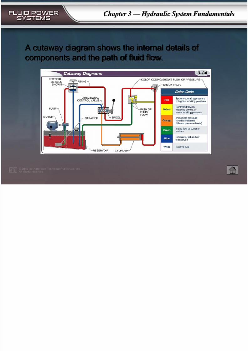
A cutaway diagram shows the internal details of components and the path of fluid flow.
7/28/2019 Hydraulic System Fundamentals
http://slidepdf.com/reader/full/hydraulic-system-fundamentals 36/37
Chapter 3 — Hydraulic System Fundamentals
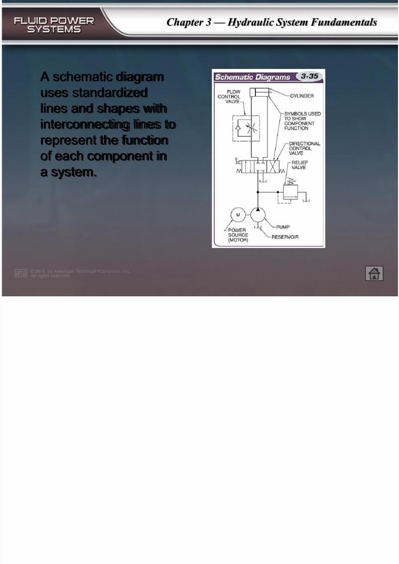
A schematic diagramuses standardized
lines and shapes with
interconnecting lines to
represent the functionof each component in
a system.
7/28/2019 Hydraulic System Fundamentals
http://slidepdf.com/reader/full/hydraulic-system-fundamentals 37/37
Chapter 3 — Hydraulic System Fundamentals
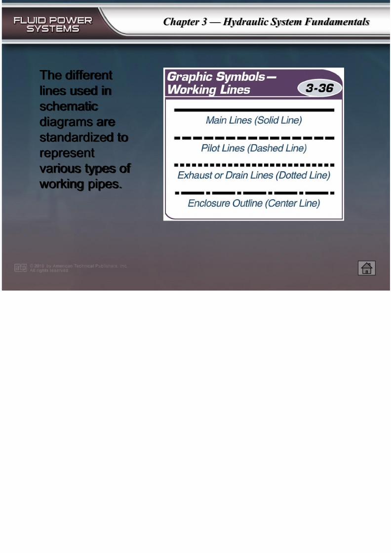
The differentlines used in
schematic
diagrams are
standardized torepresent
various types of
working pipes.