helping higher level learners to understand and use intensifiers efficiently

1
Hydraulic Seals

2
Hydraulic SealsParker HannifinPrädifa Technology Division

3
Hydraulic SealsParker HannifinPrädifa Technology Division
Precision seals for hydraulics
Elastomer seals are functionally reliable components of fluid engi-neering equipment and systems. Their advanced level of sealing technology is the result of many years of development and field experience gained in the various sectors of mechanical engineer-ing. Hydraulic sealing systems are used in a wide range of differ-ent applications, from construction machinery, which has to per-form under toughest pressure, temperature and media conditions, all the way to industrial water hydraulics in pressure intensifiers operating under extreme requirements with regard to lubrication, wear and corrosion.
Parker Hannifin offers a comprehensive product range to manu-facturers of hydraulics equipment, based on decades of experi-ence in sealing technology. Our application engineering consult-ing service assists customers with the selection of the suitable seal geometry and optimum compound. Our compound labs de-velop new materials and modify existing compounds for new ar-eas of application. Computer-aided simulation and analytical tools allow us to predict the functional performance characteristics and service life of our products, thus reducing development times and costs. Our extensive physical lab facilities are used for testing sealing elements and systems under conditions resembling their use in the field.
An extensive portfolio of sealing profiles, compounds and dimen-sions enables design engineers to find the suitable sealing system for any application. Our standard range is complemented by a host of special developments, created in close collaboration with our customers.The profile series presented in this catalogue consider existing ISO standards for installation spaces of piston seals, rod seals and wipers. The concrete contributions which Parker engineers continually make through their membership in respective stan-dardisation committees ensure that the dimensional standards established for these series conform to field requirements, now and in future.

4
Hydraulic SealsParker HannifinPrädifa Technology Division
Parker´s safety programme
Warning - user responsibilityThis document and other information from Parker Hannifin Corporation, its subsidiaries and authorized distributors provide product or system options for further investigation by users having technical expertise.
The user, through its own analysis and testing, is solely responsible for making the final selection of the system and components and assuring that all performance, endurance, maintenance, safety and warning re-quirements of the application are met. The user must analyze all aspects of the application, follow applicable industry standards, and follow the infor-mation concerning the product in the current product catalogue and in any materials provided by Parker or its subsidiaries or authorized distributors.To the extent that Parker or its subsidiaries or authorized distributors pro-vide component or system options based upon data or specifications pro-vided by the user, the user is responsible for determining that such data and specifications are suitable and sufficient for all applications and re-sponsibly foreseeable uses of the components or systems.
Range of applicationOur seals may only be used within the application parameters stated in our documents as regards compatibility with contact media, pressures, tem-peratures and time of storage. Application or use outside of the specified application parameters as well as the selection of different compounds by mistake may result in damage to life, the environment and/or equipment and facilities.
The information contained in our publications is based on know-how de-veloped over decades of experience in the manufacturing and application of seals. Despite this experience, unknown factors arising out of the practi-cal application of seals may considerably affect the overall applicability of this information in such a way that the recommendations provided herein are not to be considered generally binding.
The data for operating pressure, operating temperature, and surface speed stated in the columns represent maximum values and are interre-lated. Under extreme working conditions it is recommended not to use all maximum values simultaneously.
For special requirements (pressure, temperature, speed, etc.) please con-tact our consultancy service, so that suitable materials and/or designs can be recommended.
Compatibility of seals and operating media / cleaning agents
Due to the great diversity of operational parameters affecting fluidic devic-es and their impact on seals, it is absolutely imperative that manufacturers of these devices approve seals for functional and operational suitability under field conditions.
Furthermore, in view of the consistent increase of newly available media used as hydraulic oils, lubricants, and cleaning agents, special attention is invited to the aspect of compatibility with sealing elastomers currently in use.
Additives contained in base media in order to enhance certain functional characteristics may affect compatibility characteristics of sealing materi-als.
For this reason, it is imperative that any product equipped with our seals be tested for compatibility with operational media or cleaning agents ap-proved or specified by you either at your plant or by means of field tests prior to any field use.
We kindly ask you to comply with this notice since, as a manufacturer of seals, we are not in a position, as a matter of principle, to perform simula-tions of any and all conditions present in the final application nor of know-ing the composition of the operational media and cleaning agents used.
Design modifications We reserve the right to make design modifications without prior notifica-tion.
Prototypes and samples Prototypes and samples are produced from experimental moulds. The subsequent series production may differ in terms of production tech-niques from the prototype production unless specific agreement to the contrary was reached beforehand.
Delivery and services The delivery guarantee (availability of moulds) for individual dimensions of our range of products is limited to a period of 7 years.
Damaged moulds, including standard items, can only be replaced in case of sufficient demand. Most of the dimensions stated in this catalogue are normally (but not as a matter of course) available ex stock.
For the production of smaller quantities, special compounds, and in case of special production procedures, we reserve the right of charging a pro-rated share of set-up costs.
All deliveries and services are subject to our terms.
Quality systemsOur manufacturing sites are certified according to ISO 9001 and/or ISO/TS 16949 and/or EN9100.
CopyrightAll rights reserved by Parker Hannifin Corporation. Extracts may only be taken with permission. Modification rights reserved.
ValidityThis edition supersedes all prior documents.
5
Hydraulic SealsParker HannifinPrädifa Technology Division
Contents
Contents
General information 6
Sealing systems in typical applications 6
Sealing compounds for fluid technology 8
General installation guidelines for piston seals 18
General installation guidelines for rod seals 20
Maximum gap allowance 22
Wipers 25
Guiding elements 51
Rod seals 73
Piston seals 103
Other seal products 129
O-rings 130
Anti-extrusion rings 136
Static radial seal 139
Flange seals 141
Rotary seals 144
Sealing sets for piston accumulators 153
6
Hydraulic SealsParker HannifinPrädifa Technology Division
Gen
eral
info
rmat
ion
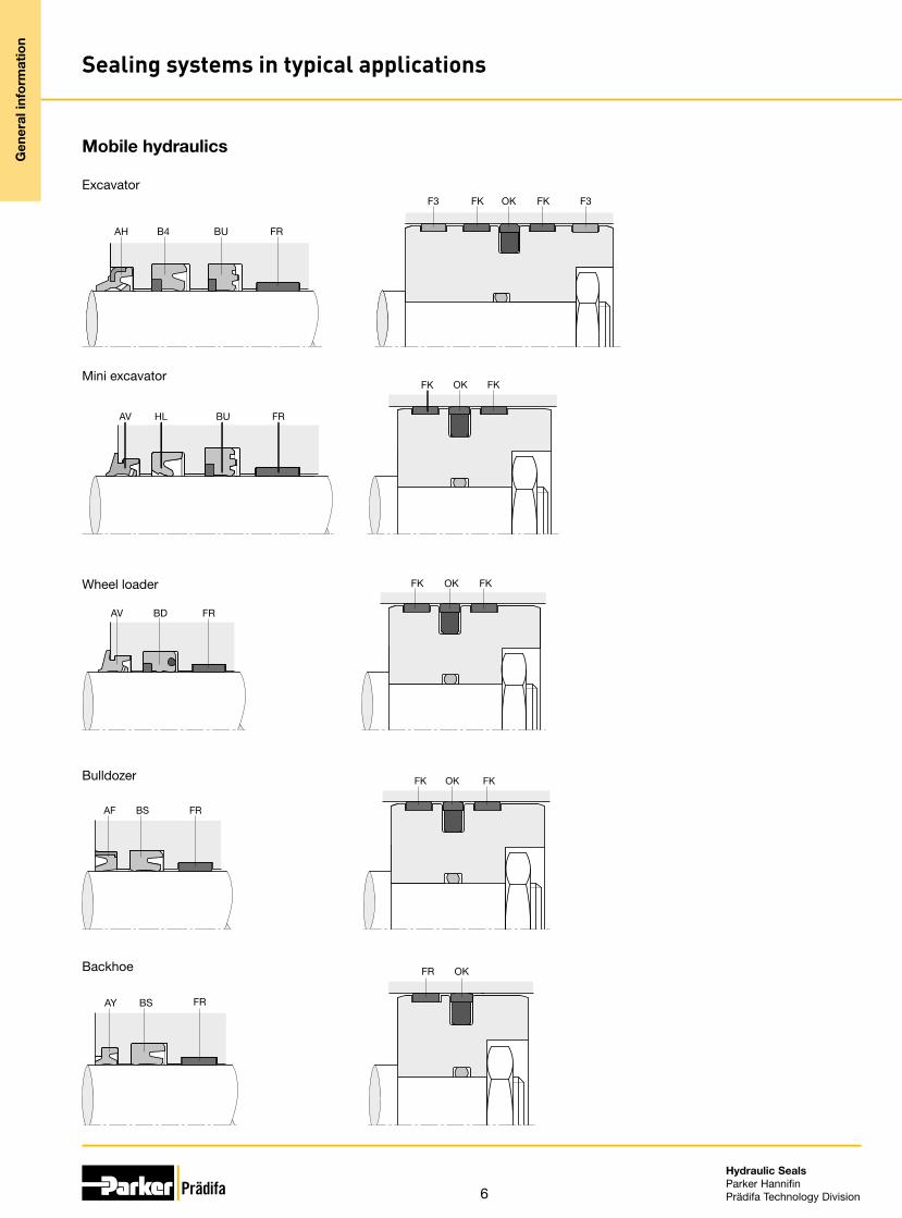
Sealing systems in typical applications
Mobile hydraulics
Excavator
AH B4 BU FR
F3 FK OK FK F3
Mini excavator
AV HL BU FR
FK OK FK
Wheel loader
AV BD FR
FK OK FK
Bulldozer
AF BS FR
FK OK FK
Backhoe
AY BS FR
FR OK

7
Hydraulic SealsParker HannifinPrädifa Technology Division
Gen
eral
info
rmat
ion
Sealing systems in typical applications
Fork lift
AY HL FR
KR FK
Skid steer
AV BS FR
KR FK
Stationary hydraulics
Industrial cylinder
A1 B3 FR
KR FK
Machine tool
A1 HL OD F3
OE F3
Injection moulding machine
AD B3 OD
FK
FR
OE FK

8
Hydraulic SealsParker HannifinPrädifa Technology Division
Gen
eral
info
rmat
ion
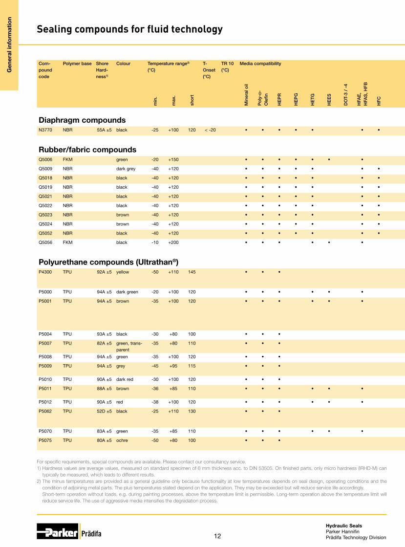
Sealing compounds for fluid technology
Compound code
Polymer base Shore Hard-ness1)
Colour Temperature range2)
(°C)T-Onset(°C)
TR 10(°C)
Media compatibility Application Standards Remarks
min
.
max
.
shor
t
Min
eral
oil
Poly
-α-
Ole
fin
HE
PR
HE
PG
HE
TG
HE
ES
DO
T-3
/ -4
HFA
E,
HFA
S, H
FB
HFC
HFD
Wat
er
Com
-p
ress
ed a
ir
Aci
ds
Lyes
Hyd
raul
ics
Pne
umat
-ic
s
Aut
omot
ive
Ind
ustr
ial
Min
ing
oil a
nd g
as
Gas
Food
, CP
I
Drin
king
w
ater
For specific requirements, special compounds are available. Please contact our consultancy service.1) Hardness values are average values, measured on standard specimen of 6 mm thickness acc. to DIN 53505. On finished parts, only micro hardness (IRHD-M) can
typically be measured, which leads to different results.2) The minus temperatures are provided as a general guideline only because functionality at low temperatures depends on seal design, operating conditions and the
condition of adjoining metal parts. The plus temperatures stated depend on the application. They may be exceeded but will reduce service life accordingly. Short-term operation without loads, e.g. during painting processes, above the temperature limit is permissible. Long-term operation above the temperature limit will
reduce service life. The use of aggressive media intensifies the degradation process.
Rubber – not resistant to mineral oilE8536 EPDM 70A ±5 black -50 +150 170 < -45 • • • • • • • • •
E0540 EPDM 80A ±5 black -50 +150 170 < -45 • • • • • • • •
E8790 EPDM 70A ±5 black -50 +150 170 < -40 • • • • • • • • • • KTW, WRAS, W 270,EN 681-1 and W 534, KIWA, NFS 61 and ACS
• standard for drinking water applications
E3676 EPDM 75A ±5 black -50 +150 200 < -45 • • • • • • • • •
E9135 EPDM 80A ±5 black -50 +150 200 < -45 • • • • • • • • • • • high tear resistance• high tensile strength
E9180 EPDM 75A ±5 black -50 +150 170 < -45 • • • • • • • • • Adblue® resistant
Rubber – resistant to mineral oilV3656 FKM 70A ±5 green -20 +200 230 < -9 • • • • • • • • • • • • • • • •
V9153 FKM 70A ±5 black -30 +200 230 < -28 • • • • • • • • • • • • • • • •
V0747 FKM 75A ±5 black -20 +200 230 < -10 • • • • • • • • • • • • • • • •
V8550 FKM 80A ±5 green -25 +200 230 < -20 • • • • • • • • • • • • • • • •
V3638 FKM 80A ±5 black -20 +200 230 < -10 • • • • • • • • • • • • • • • •
V3681 FKM 80A ±5 green -20 +200 230 < -10 • • • • • • • • • • • • • • • •
V3841 FKM 80A ±5 green -20 +200 230 < -10 • • • • • • • • • • • • • • • • • for bonded seals (rubber/metal, etc.)
V3664 FKM 85A ±5 green -20 +200 230 < -8 • • • • • • • • • • • • • • • • • improved chemical resis-tance
V9145 FKM 85A ±5 black -40 +200 230 < -38 • • • • • • • • • • • • • • • • • low-temperature compound
V9154 FKM 85A ±5 black -20 +200 230 < -10 • • • • • • • • • • • • • • • wear-resistant• for shock absorber applica-
tionsV9169 FKM 80A ±5 black -30 +200 230 < -29 • • • • • • • • • • • • • • • • • • • • • exhaust gas
• acetic acid resistant• resistant to condensate• suitable for biodiesel (RME)
applications• Fuels containing ethanol
(E85)V9134 FKM 72A ±5 green -10 +200 230 < -6 • • • • • • • • • • • • • • • • • • for bonded seals (rubber/
metal, etc.)V3839 FKM 90A ±5 green -20 +200 230 < -8 • • • • • • • • • • • • • • • • for bonded seals (rubber/
metal, etc.)N3560 NBR 60A ±5 black -40 +100 120 < -35 • • • • • • • • • • • • • • • •
N3567 NBR 70A ±5 black -20 +100 120 < -16 • • • • • • • • • • • • • • • • • • suitable for sealing plastic parts
N0674 NBR 70A ±5 black -30 +100 120 < -22 • • • • • • • • • • • • • • • • • •

9
Hydraulic SealsParker HannifinPrädifa Technology Division
Compound code
Polymer base Shore Hard-ness1)
Colour Temperature range2)
(°C)T-Onset(°C)
TR 10(°C)
Media compatibility Application Standards Remarks
min
.
max
.
shor
t
Min
eral
oil
Poly
-α-
Ole
fin
HE
PR
HE
PG
HE
TG
HE
ES
DO
T-3
/ -4
HFA
E,
HFA
S, H
FB
HFC
HFD
Wat
er
Com
-p
ress
ed a
ir
Aci
ds
Lyes
Hyd
raul
ics
Pne
umat
-ic
s
Aut
omot
ive
Ind
ustr
ial
Min
ing
oil a
nd g
as
Gas
Food
, CP
I
Drin
king
w
ater
Rubber – not resistant to mineral oilE8536 EPDM 70A ±5 black -50 +150 170 < -45 • • • • • • • • •
E0540 EPDM 80A ±5 black -50 +150 170 < -45 • • • • • • • •
E8790 EPDM 70A ±5 black -50 +150 170 < -40 • • • • • • • • • • KTW, WRAS, W 270,EN 681-1 and W 534, KIWA, NFS 61 and ACS
• standard for drinking water applications
E3676 EPDM 75A ±5 black -50 +150 200 < -45 • • • • • • • • •
E9135 EPDM 80A ±5 black -50 +150 200 < -45 • • • • • • • • • • • high tear resistance• high tensile strength
E9180 EPDM 75A ±5 black -50 +150 170 < -45 • • • • • • • • • Adblue® resistant
Rubber – resistant to mineral oilV3656 FKM 70A ±5 green -20 +200 230 < -9 • • • • • • • • • • • • • • • •
V9153 FKM 70A ±5 black -30 +200 230 < -28 • • • • • • • • • • • • • • • •
V0747 FKM 75A ±5 black -20 +200 230 < -10 • • • • • • • • • • • • • • • •
V8550 FKM 80A ±5 green -25 +200 230 < -20 • • • • • • • • • • • • • • • •
V3638 FKM 80A ±5 black -20 +200 230 < -10 • • • • • • • • • • • • • • • •
V3681 FKM 80A ±5 green -20 +200 230 < -10 • • • • • • • • • • • • • • • •
V3841 FKM 80A ±5 green -20 +200 230 < -10 • • • • • • • • • • • • • • • • • for bonded seals (rubber/metal, etc.)
V3664 FKM 85A ±5 green -20 +200 230 < -8 • • • • • • • • • • • • • • • • • improved chemical resis-tance
V9145 FKM 85A ±5 black -40 +200 230 < -38 • • • • • • • • • • • • • • • • • low-temperature compound
V9154 FKM 85A ±5 black -20 +200 230 < -10 • • • • • • • • • • • • • • • wear-resistant• for shock absorber applica-
tionsV9169 FKM 80A ±5 black -30 +200 230 < -29 • • • • • • • • • • • • • • • • • • • • • exhaust gas
• acetic acid resistant• resistant to condensate• suitable for biodiesel (RME)
applications• Fuels containing ethanol
(E85)V9134 FKM 72A ±5 green -10 +200 230 < -6 • • • • • • • • • • • • • • • • • • for bonded seals (rubber/
metal, etc.)V3839 FKM 90A ±5 green -20 +200 230 < -8 • • • • • • • • • • • • • • • • for bonded seals (rubber/
metal, etc.)N3560 NBR 60A ±5 black -40 +100 120 < -35 • • • • • • • • • • • • • • • •
N3567 NBR 70A ±5 black -20 +100 120 < -16 • • • • • • • • • • • • • • • • • • suitable for sealing plastic parts
N0674 NBR 70A ±5 black -30 +100 120 < -22 • • • • • • • • • • • • • • • • • •
Gen
eral
info
rmat
ion
Sealing compounds for fluid technology

10
Hydraulic SealsParker HannifinPrädifa Technology Division
Gen
eral
info
rmat
ion
Sealing compounds for fluid technology
Com-pound code
Polymer base Shore Hard-ness1)
Colour Temperature range2)
(°C)T-Onset(°C)
TR 10(°C)
Media compatibility Application Standards Remarks
min
.
max
.
shor
t
Min
eral
oil
Pol
y-α-
Ole
fin
HE
PR
HE
PG
HE
TG
HE
ES
DO
T-3
/ -4
HFA
E,
HFA
S, H
FB
HFC
HFD
Wat
er
Com
-p
ress
ed a
ir
Aci
ds
Lyes
Hyd
raul
ics
Pne
umat
-ic
s
Aut
omot
ive
Ind
ustr
ial
Min
ing
oil a
nd g
as
Gas
Food
, CP
I
Drin
king
w
ater
For specific requirements, special compounds are available. Please contact our consultancy service.1) Hardness values are average values, measured on standard specimen of 6 mm thickness acc. to DIN 53505. On finished parts, only micro hardness (IRHD-M) can
typically be measured, which leads to different results.2) The minus temperatures are provided as a general guideline only because functionality at low temperatures depends on seal design, operating conditions and the
condition of adjoining metal parts. The plus temperatures stated depend on the application. They may be exceeded but will reduce service life accordingly. Short-term operation without loads, e.g. during painting processes, above the temperature limit is permissible. Long-term operation above the temperature limit will
reduce service life. The use of aggressive media intensifies the degradation process.
Rubber – resistant to mineral oilN3571 NBR 70A ±5 black -35 +100 120 < -25 • • • • • • • • • • • • • • • • • •
N8612 NBR 70A ±5 black -35 +100 120 < -33 • • • • • • • • • • • • • • •
N3854 NBR 70A ±5 black -30 +100 120 < -19 • • • • • • • • • • • • • • • • • • • • KTW
N8602 NBR 70A ±5 black -50 +80 100 < -45 • • • • • • • • • • • • • • • • • • limited ozone resistance acc. to ISO 1431-1, procedure B
• good low-temperature re-sistance
N8604 NBR 70A ±5 black -30 +100 120 < -21 • • • • • • • • • • • • • • • • • • • limited ozone resistance acc. to DIN 53509/1
• DVGWN3566 NBR 75A ±5 yellow-brown -20 +100 120 < -5 • • • • • • • • • • • • • • • • • •
N3578 NBR 75A ±5 black -30 +100 120 < -23 • • • • • • • • • • • • • • • • •
N3771 NBR 80A ±5 black -15 +100 120 < -25 • • • • • • • • • • • • • • • • • • • heating oils
N3580 NBR 80A ±5 brown -25 +80 100 < -18 • • • • • • • • • • • • • • • • •
N9148 NBR 75A ±5 black -30 +100 130 < -30 • • • • • • • • • • • • • • • •
N8603 NBR 80A ±5 black -25 +100 120 < -18 • • • • • • • • • • • • • • • •
N8613 NBR 80A ±5 black -50 +80 100 < -45 • • • • • • • • • • • • • • • • • • • limited ozone resistance acc. to ISO 1431-1, procedure B
• good low-temperature re-sistance
• air brakesN3584 NBR 85A ±5 black -25 +100 120 < -20 • • • • • • • • • • • • • • • • •
N9150 NBR 70A ±5 black -35 +120 135 < -25 • • • • • • • • • • • • • • • • • •
N3582 NBR 85A ±5 brown -10 +80 120 < -2 • • • • • • • • • • • • • • • • • •
N3589 NBR 85A ±5 black -20 +100 120 < -15 • • • • • • • • • • • • • • • • • • suitable for sealing non-fer-rous metal and plastic parts
N3763 NBR 85A ±5 brown -25 +100 120 < -20 • • • • • • • • • • • • • • • • • •
N3544 NBR 90A ±5 black -25 +100 120 < -18 • • • • • • • • • • • • • • • • • •
N3587 NBR 90A ±5 black -25 +100 120 < -10 • • • • • • • • • • • • • • • • • • only for wipers
N3764 NBR 90A ±5 brown -10 +100 120 < -4 • • • • • • • • • • • • • • • • •
N1173 HNBR 75A ±5 black -25 +150 170 < -20 • • • • • • • • • • • • • • • • • • suitable for R134a, HFO 1234yf
N8615 HNBR/NBM 70A ±5 black -25 +130 150 < -22 • • • • • • • • • • • • • • • • •
N3573 HNBR/NBM 75A ±5 black -20 +150 170 < -16 • • • • • • • • • • • • • • • • •
N9192 HNBR 80A ±5 grey -35 +130 150 < -35 • • • • • • • • • • • • • • • • • • Adblue® resistant
KB163
KA183 HNBR 85A ±5 black -30 +130 150 < -35 • • • • • • • • • • • • • • • • • • good low-temperature resistance• NORSOK M-710 compliant
N9182 HNBR 75A ±5 black -30 +130 150 < -25 • • • • • • • • • • • • • • • • • • Adblue® resistant
N3510 HNBR/NBM 85A ±5 black -20 +150 170 < -18 • • • • • • • • • • • • • • • • •
N3512 HNBR/NBM 90A ±5 black -20 +150 170 < -16 • • • • • • • • • • • • • • • • •
N8526 HNBR/NBM 90A ±5 black -20 +150 170 < -16 • • • • • • • • • • • • • • • • • • outstanding wear resistance
N8557 HNBR 75A ±5 black -35 +130 150 < -35 • • • • • • • • • • • • • • • • • • central hydraulics media

11
Hydraulic SealsParker HannifinPrädifa Technology Division
Com-pound code
Polymer base Shore Hard-ness1)
Colour Temperature range2)
(°C)T-Onset(°C)
TR 10(°C)
Media compatibility Application Standards Remarks
min
.
max
.
shor
t
Min
eral
oil
Pol
y-α-
Ole
fin
HE
PR
HE
PG
HE
TG
HE
ES
DO
T-3
/ -4
HFA
E,
HFA
S, H
FB
HFC
HFD
Wat
er
Com
-p
ress
ed a
ir
Aci
ds
Lyes
Hyd
raul
ics
Pne
umat
-ic
s
Aut
omot
ive
Ind
ustr
ial
Min
ing
oil a
nd g
as
Gas
Food
, CP
I
Drin
king
w
ater
Rubber – resistant to mineral oilN3571 NBR 70A ±5 black -35 +100 120 < -25 • • • • • • • • • • • • • • • • • •
N8612 NBR 70A ±5 black -35 +100 120 < -33 • • • • • • • • • • • • • • •
N3854 NBR 70A ±5 black -30 +100 120 < -19 • • • • • • • • • • • • • • • • • • • • KTW
N8602 NBR 70A ±5 black -50 +80 100 < -45 • • • • • • • • • • • • • • • • • • limited ozone resistance acc. to ISO 1431-1, procedure B
• good low-temperature re-sistance
N8604 NBR 70A ±5 black -30 +100 120 < -21 • • • • • • • • • • • • • • • • • • • limited ozone resistance acc. to DIN 53509/1
• DVGWN3566 NBR 75A ±5 yellow-brown -20 +100 120 < -5 • • • • • • • • • • • • • • • • • •
N3578 NBR 75A ±5 black -30 +100 120 < -23 • • • • • • • • • • • • • • • • •
N3771 NBR 80A ±5 black -15 +100 120 < -25 • • • • • • • • • • • • • • • • • • • heating oils
N3580 NBR 80A ±5 brown -25 +80 100 < -18 • • • • • • • • • • • • • • • • •
N9148 NBR 75A ±5 black -30 +100 130 < -30 • • • • • • • • • • • • • • • •
N8603 NBR 80A ±5 black -25 +100 120 < -18 • • • • • • • • • • • • • • • •
N8613 NBR 80A ±5 black -50 +80 100 < -45 • • • • • • • • • • • • • • • • • • • limited ozone resistance acc. to ISO 1431-1, procedure B
• good low-temperature re-sistance
• air brakesN3584 NBR 85A ±5 black -25 +100 120 < -20 • • • • • • • • • • • • • • • • •
N9150 NBR 70A ±5 black -35 +120 135 < -25 • • • • • • • • • • • • • • • • • •
N3582 NBR 85A ±5 brown -10 +80 120 < -2 • • • • • • • • • • • • • • • • • •
N3589 NBR 85A ±5 black -20 +100 120 < -15 • • • • • • • • • • • • • • • • • • suitable for sealing non-fer-rous metal and plastic parts
N3763 NBR 85A ±5 brown -25 +100 120 < -20 • • • • • • • • • • • • • • • • • •
N3544 NBR 90A ±5 black -25 +100 120 < -18 • • • • • • • • • • • • • • • • • •
N3587 NBR 90A ±5 black -25 +100 120 < -10 • • • • • • • • • • • • • • • • • • only for wipers
N3764 NBR 90A ±5 brown -10 +100 120 < -4 • • • • • • • • • • • • • • • • •
N1173 HNBR 75A ±5 black -25 +150 170 < -20 • • • • • • • • • • • • • • • • • • suitable for R134a, HFO 1234yf
N8615 HNBR/NBM 70A ±5 black -25 +130 150 < -22 • • • • • • • • • • • • • • • • •
N3573 HNBR/NBM 75A ±5 black -20 +150 170 < -16 • • • • • • • • • • • • • • • • •
N9192 HNBR 80A ±5 grey -35 +130 150 < -35 • • • • • • • • • • • • • • • • • • Adblue® resistant
KB163
KA183 HNBR 85A ±5 black -30 +130 150 < -35 • • • • • • • • • • • • • • • • • • good low-temperature resistance• NORSOK M-710 compliant
N9182 HNBR 75A ±5 black -30 +130 150 < -25 • • • • • • • • • • • • • • • • • • Adblue® resistant
N3510 HNBR/NBM 85A ±5 black -20 +150 170 < -18 • • • • • • • • • • • • • • • • •
N3512 HNBR/NBM 90A ±5 black -20 +150 170 < -16 • • • • • • • • • • • • • • • • •
N8526 HNBR/NBM 90A ±5 black -20 +150 170 < -16 • • • • • • • • • • • • • • • • • • outstanding wear resistance
N8557 HNBR 75A ±5 black -35 +130 150 < -35 • • • • • • • • • • • • • • • • • • central hydraulics media
Gen
eral
info
rmat
ion
Sealing compounds for fluid technology
12
Hydraulic SealsParker HannifinPrädifa Technology Division
Gen
eral
info
rmat
ion
Sealing compounds for fluid technology
Com-pound code
Polymer base Shore Hard-ness1)
Colour Temperature range2)
(°C)T-Onset(°C)
TR 10(°C)
Media compatibility Application Standards Remarks
min
.
max
.
shor
t
Min
eral
oil
Pol
y-α-
Ole
fin
HE
PR
HE
PG
HE
TG
HE
ES
DO
T-3
/ -4
HFA
E,
HFA
S, H
FB
HFC
HFD
Wat
er
Com
-p
ress
ed a
ir
Aci
ds
Lyes
Hyd
raul
ics
Pne
umat
-ic
s
Aut
omot
ive
Ind
ustr
ial
Min
ing
oil a
nd g
as
Gas
Food
, CP
I
Drin
king
w
ater
For specific requirements, special compounds are available. Please contact our consultancy service.1) Hardness values are average values, measured on standard specimen of 6 mm thickness acc. to DIN 53505. On finished parts, only micro hardness (IRHD-M) can
typically be measured, which leads to different results.2) The minus temperatures are provided as a general guideline only because functionality at low temperatures depends on seal design, operating conditions and the
condition of adjoining metal parts. The plus temperatures stated depend on the application. They may be exceeded but will reduce service life accordingly. Short-term operation without loads, e.g. during painting processes, above the temperature limit is permissible. Long-term operation above the temperature limit will
reduce service life. The use of aggressive media intensifies the degradation process.
Diaphragm compoundsN3770 NBR 55A ±5 black -25 +100 120 < -20 • • • • • • • • • • • • • • • • • • low gas permeability
Rubber/fabric compoundsQ5006 FKM green -20 +150 • • • • • • • • • • •
Q5009 NBR dark grey -40 +120 • • • • • • • • • • • • • high-pressure cleaners
Q5018 NBR black -40 +120 • • • • • • • • • • • • • high-pressure cleaners
Q5019 NBR black -40 +120 • • • • • • • • • •
Q5021 NBR black -40 +120 • • • • • • • • • •
Q5022 NBR black -40 +120 • • • • • • • • • •
Q5023 NBR brown -40 +120 • • • • • • • • • • • • • high-pressure cleaners
Q5024 NBR brown -40 +120 • • • • • • • • • • • • • high-pressure cleaners
Q5052 NBR black -40 +120 • • • • • • • • • • • • • high-pressure cleaners
Q5056 FKM black -10 +200 • • • • • • • • • • • • • • • aramid fabrics
Polyurethane compounds (Ultrathan®)P4300 TPU 92A ±5 yellow -50 +110 145 • • • • • • • excellent high-temperature be-
haviour• excellent dynamic behaviour
P5000 TPU 94A ±5 dark green -20 +100 120 • • • • • • • • • • • • • • FDA • good hydrolysis resistance
P5001 TPU 94A ±5 brown -35 +100 120 • • • • • • • • • • • • • • exceeds VDMA Guideline 24568 for high-performance hydraulic oils of wa-ter hazard class 0
• good hydrolysis resistance
P5004 TPU 93A ±5 black -30 +80 100 • • • • • •
P5007 TPU 82A ±5 green, trans-parent
-35 +80 110 • • • • •
P5008 TPU 94A ±5 green -35 +100 120 • • • • • • • • • •
P5009 TPU 94A ±5 grey -45 +95 115 • • • • • • • • excellent low-temperature be-haviour
P5010 TPU 90A ±5 dark red -30 +100 120 • • • • • •
P5011 TPU 88A ±5 brown -36 +85 110 • • • • • • • • • • • • friction-optimized• very good wear resistance
P5012 TPU 90A ±5 red -38 +100 120 • • • • • • • • • • • • • central hydraulics media
P5062 TPU 52D ±5 black -25 +110 130 • • • • • • • • • • very good extrusion resistance• low friction• good hydrolysis resistance
P5070 TPU 83A ±5 green -35 +85 110 • • • • • • • • •
P5075 TPU 80A ±5 ochre -50 +80 100 • • • • • • • • outstanding low-temp. behaviour• outstanding dynamic behaviour

13
Hydraulic SealsParker HannifinPrädifa Technology Division
Com-pound code
Polymer base Shore Hard-ness1)
Colour Temperature range2)
(°C)T-Onset(°C)
TR 10(°C)
Media compatibility Application Standards Remarks
min
.
max
.
shor
t
Min
eral
oil
Pol
y-α-
Ole
fin
HE
PR
HE
PG
HE
TG
HE
ES
DO
T-3
/ -4
HFA
E,
HFA
S, H
FB
HFC
HFD
Wat
er
Com
-p
ress
ed a
ir
Aci
ds
Lyes
Hyd
raul
ics
Pne
umat
-ic
s
Aut
omot
ive
Ind
ustr
ial
Min
ing
oil a
nd g
as
Gas
Food
, CP
I
Drin
king
w
ater
Diaphragm compoundsN3770 NBR 55A ±5 black -25 +100 120 < -20 • • • • • • • • • • • • • • • • • • low gas permeability
Rubber/fabric compoundsQ5006 FKM green -20 +150 • • • • • • • • • • •
Q5009 NBR dark grey -40 +120 • • • • • • • • • • • • • high-pressure cleaners
Q5018 NBR black -40 +120 • • • • • • • • • • • • • high-pressure cleaners
Q5019 NBR black -40 +120 • • • • • • • • • •
Q5021 NBR black -40 +120 • • • • • • • • • •
Q5022 NBR black -40 +120 • • • • • • • • • •
Q5023 NBR brown -40 +120 • • • • • • • • • • • • • high-pressure cleaners
Q5024 NBR brown -40 +120 • • • • • • • • • • • • • high-pressure cleaners
Q5052 NBR black -40 +120 • • • • • • • • • • • • • high-pressure cleaners
Q5056 FKM black -10 +200 • • • • • • • • • • • • • • • aramid fabrics
Polyurethane compounds (Ultrathan®)P4300 TPU 92A ±5 yellow -50 +110 145 • • • • • • • excellent high-temperature be-
haviour• excellent dynamic behaviour
P5000 TPU 94A ±5 dark green -20 +100 120 • • • • • • • • • • • • • • FDA • good hydrolysis resistance
P5001 TPU 94A ±5 brown -35 +100 120 • • • • • • • • • • • • • • exceeds VDMA Guideline 24568 for high-performance hydraulic oils of wa-ter hazard class 0
• good hydrolysis resistance
P5004 TPU 93A ±5 black -30 +80 100 • • • • • •
P5007 TPU 82A ±5 green, trans-parent
-35 +80 110 • • • • •
P5008 TPU 94A ±5 green -35 +100 120 • • • • • • • • • •
P5009 TPU 94A ±5 grey -45 +95 115 • • • • • • • • excellent low-temperature be-haviour
P5010 TPU 90A ±5 dark red -30 +100 120 • • • • • •
P5011 TPU 88A ±5 brown -36 +85 110 • • • • • • • • • • • • friction-optimized• very good wear resistance
P5012 TPU 90A ±5 red -38 +100 120 • • • • • • • • • • • • • central hydraulics media
P5062 TPU 52D ±5 black -25 +110 130 • • • • • • • • • • very good extrusion resistance• low friction• good hydrolysis resistance
P5070 TPU 83A ±5 green -35 +85 110 • • • • • • • • •
P5075 TPU 80A ±5 ochre -50 +80 100 • • • • • • • • outstanding low-temp. behaviour• outstanding dynamic behaviour
Gen
eral
info
rmat
ion
Sealing compounds for fluid technology

14
Hydraulic SealsParker HannifinPrädifa Technology Division
Gen
eral
info
rmat
ion
Sealing compounds for fluid technology
Com-pound code
Polymer base Shore Hard-ness1)
Colour Temperature range2)
(°C)T-Onset(°C)
TR 10(°C)
Media compatibility Application Standards Remarks
min
.
max
.
shor
t
Min
eral
oil
Pol
y-α-
Ole
fin
HE
PR
HE
PG
HE
TG
HE
ES
DO
T-3
/ -4
HFA
E,
HFA
S, H
FB
HFC
HFD
Wat
er
Com
-p
ress
ed a
ir
Aci
ds
Lyes
Hyd
raul
ics
Pne
umat
-ic
s
Aut
omot
ive
Ind
ustr
ial
Min
ing
oil a
nd g
as
Gas
Food
, CP
I
Drin
king
w
ater
For specific requirements, special compounds are available. Please contact our consultancy service.1) Hardness values are average values, measured on standard specimen of 6 mm thickness acc. to DIN 53505. On finished parts, only micro hardness (IRHD-M) can
typically be measured, which leads to different results.2) The minus temperatures are provided as a general guideline only because functionality at low temperatures depends on seal design, operating conditions and the
condition of adjoining metal parts. The plus temperatures stated depend on the application. They may be exceeded but will reduce service life accordingly. Short-term operation without loads, e.g. during painting processes, above the temperature limit is permissible. Long-term operation above the temperature limit will
reduce service life. The use of aggressive media intensifies the degradation process.
Polyurethane compounds (Ultrathan®)P5080 TPU 88A ±5 light green -40 +85 110 • • • • • • • • • • • stick-slip free sliding
• central hydraulics mediaP6000 TPU 95A ±5 charcoal-
grey-35 +110 120 • • • • • • • • excellent wear resistance
P6030 TPU 94A ±5 orange -35 +105 120 • • • • • • • • • • high wear resistance
Plastic materialsW5005 TPE-E 40D ±5 nature -40 +100 120 • • • • • •
W5035 TPE-E 55D ±5 grey -40 +100 120 • • • • • •
W5001 POM nature -40 +100 120 • • • • • • • • • • • • • • • •
W5007 PA 6.6 nature -40 +110 130 • • • • • • • • • • • • • • • • • •
W5019 PA 6.6 + 30 % glas fibre
black -40 +120 140 • • • • • • • • • • • • • • • • • • •
W5059 PA 6.6 + 35 % glas fibre
black -40 +140 160 • • • • • • • • • • • • • • • • • •
W5098 PA 12 72D black -50 +100 150 • • • • • • • • • • • • • • • • • • •
W5097 PPA + 60 % glas fibre
dark grey -40 +200 220 • • • • • • • • •
W5306 PPS + 55 % glas fibre
nature -40 +200 220 • • • • • • • • • • • • • • • •
W5029 PEI + 10 % glas fibre
nature -50 +170 190 • • • • • glass-fibre reinforced
W5052 PEEK nature -40 +200 250 • • • • • • • • • • • • • • • • • rotary transmissions
W5082 PEEK + 30 % glas fibre
nature -40 +250 300 • • • • • • • • • • • • • • • •
W5314 PEEK + 30 % carbon fibre
black -40 +250 300 • • • • • • • • • • • • • • • •
nobrox® W6101
PK nature -40 +120 135 • • • • • • • • • • • • • • • • • • FDA • limited resistance to acids and lyees
nobrox®
W6100PK orange
brown-40 +120 135 • • • • • • • • • • • • • • • • limited resistance to acids and
lyeesnobrox® W5071
PK green (natural)
-40 +120 135 • • • • • • • • • • • • • • • limited resistance to acids and lyees• rotary transmissions
nobrox® W5072
PK + 15 % glas fibre
black -40 +120 135 • • • • • • • • • •
O-ring compounds for slipper sealsN0674 NBR 70A ±5 black -30 +100 120 < -22 • • • • • • • • • • • • • • • • • • • standard O-ring compound for
slipper sealsV0747 FKM 75A ±5 black -20 +200 230 < -10 • • • • • • • • • • • • • • •
N0756 NBR 75A ±5 black -50 +110 120 < -40 • • • • • • • • • • • • • • •
E0540 EPDM 80A ±5 black -40 +150 170 < -45 • • • • • • • •
N3578 NBR 75A ±5 black -30 +110 120 < -26 • • • • • • • • • • • • •

15
Hydraulic SealsParker HannifinPrädifa Technology Division
Com-pound code
Polymer base Shore Hard-ness1)
Colour Temperature range2)
(°C)T-Onset(°C)
TR 10(°C)
Media compatibility Application Standards Remarks
min
.
max
.
shor
t
Min
eral
oil
Pol
y-α-
Ole
fin
HE
PR
HE
PG
HE
TG
HE
ES
DO
T-3
/ -4
HFA
E,
HFA
S, H
FB
HFC
HFD
Wat
er
Com
-p
ress
ed a
ir
Aci
ds
Lyes
Hyd
raul
ics
Pne
umat
-ic
s
Aut
omot
ive
Ind
ustr
ial
Min
ing
oil a
nd g
as
Gas
Food
, CP
I
Drin
king
w
ater
Polyurethane compounds (Ultrathan®)P5080 TPU 88A ±5 light green -40 +85 110 • • • • • • • • • • • stick-slip free sliding
• central hydraulics mediaP6000 TPU 95A ±5 charcoal-
grey-35 +110 120 • • • • • • • • excellent wear resistance
P6030 TPU 94A ±5 orange -35 +105 120 • • • • • • • • • • high wear resistance
Plastic materialsW5005 TPE-E 40D ±5 nature -40 +100 120 • • • • • •
W5035 TPE-E 55D ±5 grey -40 +100 120 • • • • • •
W5001 POM nature -40 +100 120 • • • • • • • • • • • • • • • •
W5007 PA 6.6 nature -40 +110 130 • • • • • • • • • • • • • • • • • •
W5019 PA 6.6 + 30 % glas fibre
black -40 +120 140 • • • • • • • • • • • • • • • • • • •
W5059 PA 6.6 + 35 % glas fibre
black -40 +140 160 • • • • • • • • • • • • • • • • • •
W5098 PA 12 72D black -50 +100 150 • • • • • • • • • • • • • • • • • • •
W5097 PPA + 60 % glas fibre
dark grey -40 +200 220 • • • • • • • • •
W5306 PPS + 55 % glas fibre
nature -40 +200 220 • • • • • • • • • • • • • • • •
W5029 PEI + 10 % glas fibre
nature -50 +170 190 • • • • • glass-fibre reinforced
W5052 PEEK nature -40 +200 250 • • • • • • • • • • • • • • • • • rotary transmissions
W5082 PEEK + 30 % glas fibre
nature -40 +250 300 • • • • • • • • • • • • • • • •
W5314 PEEK + 30 % carbon fibre
black -40 +250 300 • • • • • • • • • • • • • • • •
nobrox® W6101
PK nature -40 +120 135 • • • • • • • • • • • • • • • • • • FDA • limited resistance to acids and lyees
nobrox®
W6100PK orange
brown-40 +120 135 • • • • • • • • • • • • • • • • limited resistance to acids and
lyeesnobrox® W5071
PK green (natural)
-40 +120 135 • • • • • • • • • • • • • • • limited resistance to acids and lyees• rotary transmissions
nobrox® W5072
PK + 15 % glas fibre
black -40 +120 135 • • • • • • • • • •
Gen
eral
info
rmat
ion
Sealing compounds for fluid technology
O-ring compounds for slipper sealsN0674 NBR 70A ±5 black -30 +100 120 < -22 • • • • • • • • • • • • • • • • • • • standard O-ring compound for
slipper sealsV0747 FKM 75A ±5 black -20 +200 230 < -10 • • • • • • • • • • • • • • •
N0756 NBR 75A ±5 black -50 +110 120 < -40 • • • • • • • • • • • • • • •
E0540 EPDM 80A ±5 black -40 +150 170 < -45 • • • • • • • •
N3578 NBR 75A ±5 black -30 +110 120 < -26 • • • • • • • • • • • • •

16
Hydraulic SealsParker HannifinPrädifa Technology Division
Gen
eral
info
rmat
ion
Sealing compounds for fluid technology
Com-pound code
Polymer base Shore Hard-ness1)
Colour Temperature range2)
(°C)T-Onset(°C)
TR 10(°C)
Media compatibility Application Standards Remarks
min
.
max
.
shor
t
Min
eral
oil
Pol
y-α-
Ole
fin
HE
PR
HE
PG
HE
TG
HE
ES
DO
T-3
/ -4
HFA
E,
HFA
S, H
FB
HFC
HFD
Wat
er
Com
-p
ress
ed a
ir
Aci
ds
Lyes
Hyd
raul
ics
Pne
umat
-ic
s
Aut
omot
ive
Ind
ustr
ial
Min
ing
oil a
nd g
as
Gas
Food
, CP
I
Drin
king
w
ater
For specific requirements, special compounds are available. Please contact our consultancy service.1) Hardness values are average values, measured on standard specimen of 6 mm thickness acc. to DIN 53505. On finished parts, only micro hardness (IRHD-M) can
typically be measured, which leads to different results.2) The minus temperatures are provided as a general guideline only because functionality at low temperatures depends on seal design, operating conditions and the
condition of adjoining metal parts. The plus temperatures stated depend on the application. They may be exceeded but will reduce service life accordingly. Short-term operation without loads, e.g. during painting processes, above the temperature limit is permissible. Long-term operation above the temperature limit will
reduce service life. The use of aggressive media intensifies the degradation process.
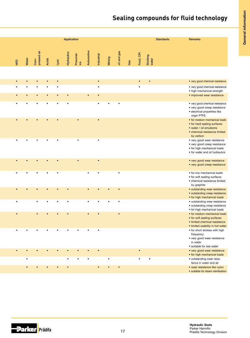
Polon® compounds001 Virgin PTFE white -190 +230 • • • • • • • • • • • • • • • • • • very good chemical resistance
003 Virgin TFM white -190 +230 • • • • • • • • • • • • • • • • • very good chemical resistance• high mechanical strength
012 modified PTFE
dark green -190 +230 • • • • • • • • • • • • • • • • • • improved wear resistance
025 PTFE + 15 % glas fibre
dark green -190 +290 • • • • • • • • • • • • • • • • • • • very good chemical resistance• very good creep resistance• electrical properties like
virgin PTFE031 PTFE
+ 15 % carbon
black -190 +290 • • • • • • • • • • • • • • • • • for medium mechanical loads• for hard sealing surfaces• water / oil emulsions• chemical resistance limited
by carbon003 PFTE
+ 23 % carbon + 2 % graphite
black -190 +315 • • • • • • • • • • • • • • • • • very good wear resistance• very good creep resistance• for high mechanical loads• for water and oil hydraulics
033 PTFE+ 25 %carbon
black -190 +315 • • • • • • • • • • • • • • • • • very good wear resistance• very good creep resistance
044 PTFE+ 15 %graphite
black -190 +230 • • • • • • • • • • • • • • • • • • for low mechanical loads• for soft sealing surfaces• chemical resistance limited
by graphite052 PTFE
+ 40 %bronze
bronze -156 +260 • • • • • • • • • • • • • • • • • • • • outstanding wear resistance• outstanding creep resistance• for high mechanical loads
062 PTFE + 60 % bronze
bronze -156 +260 • • • • • • • • • • • • • • • • • • • outstanding wear resistance• outstanding creep resistance• for high mechanical loads
067 PTFE+ 10 %ekonol
beige -260 +320 • • • • • • • • • • • • • • • • • • for medium mechanical loads• for soft sealing surfaces• limited chemical resistance• limited usability in hot water
074 PTFE+ 10 %carbon fibre
greyish -260 +310 • • • • • • • • • • • • • • • • • • • for short strokes with high frequency
• very good wear resistance in water
• suitable for sea water083 TPU 72D ±5 yellow, trans-
parent-20 +100 • • • • • • • • • • • • • • • • • • • • very good wear resistance
• for high mechanical loads314 UHMW-PE white -200 +80 • • • • • • • • • • • outstanding wear resis-
tance in water and air314 PVDF white/yellow -30 +140 • • • • • • • • • • • • • • • • • wear resistance like nylon
• suitable for steam sterilisation
17
Hydraulic SealsParker HannifinPrädifa Technology Division
Com-pound code
Polymer base Shore Hard-ness1)
Colour Temperature range2)
(°C)T-Onset(°C)
TR 10(°C)
Media compatibility Application Standards Remarks
min
.
max
.
shor
t
Min
eral
oil
Pol
y-α-
Ole
fin
HE
PR
HE
PG
HE
TG
HE
ES
DO
T-3
/ -4
HFA
E,
HFA
S, H
FB
HFC
HFD
Wat
er
Com
-p
ress
ed a
ir
Aci
ds
Lyes
Hyd
raul
ics
Pne
umat
-ic
s
Aut
omot
ive
Ind
ustr
ial
Min
ing
oil a
nd g
as
Gas
Food
, CP
I
Drin
king
w
ater
Polon® compounds001 Virgin PTFE white -190 +230 • • • • • • • • • • • • • • • • • • very good chemical resistance
003 Virgin TFM white -190 +230 • • • • • • • • • • • • • • • • • very good chemical resistance• high mechanical strength
012 modified PTFE
dark green -190 +230 • • • • • • • • • • • • • • • • • • improved wear resistance
025 PTFE + 15 % glas fibre
dark green -190 +290 • • • • • • • • • • • • • • • • • • • very good chemical resistance• very good creep resistance• electrical properties like
virgin PTFE031 PTFE
+ 15 % carbon
black -190 +290 • • • • • • • • • • • • • • • • • for medium mechanical loads• for hard sealing surfaces• water / oil emulsions• chemical resistance limited
by carbon003 PFTE
+ 23 % carbon + 2 % graphite
black -190 +315 • • • • • • • • • • • • • • • • • very good wear resistance• very good creep resistance• for high mechanical loads• for water and oil hydraulics
033 PTFE+ 25 %carbon
black -190 +315 • • • • • • • • • • • • • • • • • very good wear resistance• very good creep resistance
044 PTFE+ 15 %graphite
black -190 +230 • • • • • • • • • • • • • • • • • • for low mechanical loads• for soft sealing surfaces• chemical resistance limited
by graphite052 PTFE
+ 40 %bronze
bronze -156 +260 • • • • • • • • • • • • • • • • • • • • outstanding wear resistance• outstanding creep resistance• for high mechanical loads
062 PTFE + 60 % bronze
bronze -156 +260 • • • • • • • • • • • • • • • • • • • outstanding wear resistance• outstanding creep resistance• for high mechanical loads
067 PTFE+ 10 %ekonol
beige -260 +320 • • • • • • • • • • • • • • • • • • for medium mechanical loads• for soft sealing surfaces• limited chemical resistance• limited usability in hot water
074 PTFE+ 10 %carbon fibre
greyish -260 +310 • • • • • • • • • • • • • • • • • • • for short strokes with high frequency
• very good wear resistance in water
• suitable for sea water083 TPU 72D ±5 yellow, trans-
parent-20 +100 • • • • • • • • • • • • • • • • • • • • very good wear resistance
• for high mechanical loads314 UHMW-PE white -200 +80 • • • • • • • • • • • outstanding wear resis-
tance in water and air314 PVDF white/yellow -30 +140 • • • • • • • • • • • • • • • • • wear resistance like nylon
• suitable for steam sterilisation
Gen
eral
info
rmat
ion
Sealing compounds for fluid technology

18
Hydraulic SealsParker HannifinPrädifa Technology Division
Gen
eral
info
rmat
ion
General installation guidelines for piston seals
International (ISO) and national (DIN) standards for seal housing dimensions are in place and should be considered. For seals re-quiring a special groove, e.g. special seals, valve seals, rotor seals etc., the groove dimensions are stated separately. In general, the surface finishes, leading edge chamfers and dimensions stated here have already proved themselves and will mostly be found in the standards.
We recommend that customers adhere to the tolerances and sur-face finishes stated in this catalogue. This is a prerequisite for easy, damage-free installation and for the seal to retain the prop-erties stated in this catalogue. Surfaces: Grinding as final machining process for dynamic seal-ing surfaces is not sufficient. These surfaces have to be polished afterwards.
Radii: As for the necessary radii (r) please refer to the respective profile data or the applicable standards.
rounded and smooth
Solid piston
Split piston
R3
R3C = D – d
4
20 - 30°
R4
R1
R2
C
Ø D
Ø
D
Ø d
Ø d
r2r1r 1
r 2
Surfaces
Dynamic sealing surfacesFor rubber and PTFE productsR1: Rz 1.0 µm / Ra 0.2 µm80 % ≤ *tp1 ≤ 95 %
For polyurethane productsR1: Rz 1.6 µm / Ra 0.4 µm60 % ≤ *tp1 ≤ 80 %
Static sealing surfacesR2: Rz 6.3 µm / Ra 0.8 µm*tp2 ≥ 60 %
Non-sealing surfaces and lead-in chamfers R3: Rz 16 µm / Ra 4 µmR4: Rz 10 µm / Ra 1.6 µm
* Measured in a depth of 25 % of the Rt-value based on a refer-ence level (zero line) set at 5 % bearing area.
Stretchable seals with tight fit
When seals have a tight fit the piston shoulder diameter can be re-duced to ease assembly. By adapting this principal, metal to metal contact, caused by the piston contacting the cylinder wall surface under high transverse loads, is avoided.
Radii: As for the necessary radii please refer to the respective pro-file data or the applicable standards.
Ø d
Ø D
r 2r 3
r1
1∕3 - ½ S *
S
“X”
“X”

19
Hydraulic SealsParker HannifinPrädifa Technology Division
Gen
eral
info
rmat
ion
General installation guidelines for piston seals
PTFE-seals
Installation guidelines for PTFE sealsThe grooves must be carefully cleaned and deburred. The cyl-inder bore must have a lead-in chamfer. When fitting the piston sealing ring there is always the danger that the ring may tilt and be sheared off by normal lead-in chamfers (see fig.). We therefore recommend that up to a cylinder diameter of 230 mm a lead-in chamfer according to detail “A” is considered. In the case of small-er rings which are especially liable to bending we recommend an open-groove design for diameters smaller than 30 mm.
L
15°Piston seal ringO-ring
Fig. 1
A
10 - 15°
Ø D
+ a
Ø D
b0.7 L
b
Detail A
Fig. 2
Ø D min. a max. b
≤ 45 0.8 2.4
45 - 175 1 3
175 - 230 1.5 4.5
Assembly instruction for PTFE sealsInstall the O-ring in the groove as per normal practice. Piston seal-ing rings of up to 100 mm diameter and wall thickness of over 1.6 mm should be „slowly“ expanded and fitted with an assembly tool (see fig. 3). Larger rings can be expanded by hand. Uneven stretching or overstretching must be avoided under all circum-stances.
Should it be necessary to pull the rings over existing guide ring grooves, then these grooves must be covered with plastic tape, or alternatively the expanding mandrel must reach the groove in question (see fig. 3). This ensures that the piston sealing ring does not snap into the wrong groove. The use of a burnishing shell is recommended when the assembly of a piston is made difficult by an overstretched ring or when the cylinder has an inadequate lead-in chamfer (see fig. 4).Assembly aids can be manufactured conveniently out of metal. However, in many cases polyamide or POM is also suitable.
Expanding jacketExpanding mandrel Piston seal
Groove cover
O-Ring 5° Cone Inside Ø of the piston sealing ring less 3 mm
Piston
Fig. 3
L Ø D
Burnishing shell
Fig. 4
20
Hydraulic SealsParker HannifinPrädifa Technology Division
Gen
eral
info
rmat
ion
General installation guidelines for rod seals
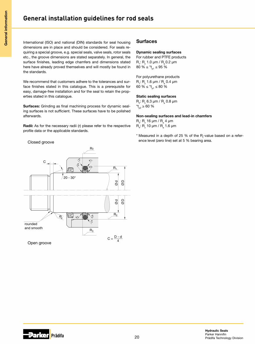
International (ISO) and national (DIN) standards for seal housing dimensions are in place and should be considered. For seals re-quiring a special groove, e.g. special seals, valve seals, rotor seals etc., the groove dimensions are stated separately. In general, the surface finishes, leading edge chamfers and dimensions stated here have already proved themselves and will mostly be found in the standards.
We recommend that customers adhere to the tolerances and sur-face finishes stated in this catalogue. This is a prerequisite for easy, damage-free installation and for the seal to retain the prop-erties stated in this catalogue. Surfaces: Grinding as final machining process for dynamic seal-ing surfaces is not sufficient. These surfaces have to be polished afterwards.
Radii: As for the necessary radii (r) please refer to the respective profile data or the applicable standards.
Closed groove
Open groove
rounded and smooth
R3
20 - 30°
Ø d
Ø D
Ø d
Ø D
C
R3
R4
R1
R2
C = D - d4
r 1
r1
r 2
r2
r1r2r 2
Surfaces
Dynamic sealing surfacesFor rubber and PTFE productsR1: Rz 1.0 µm / Ra 0.2 µm80 % ≤ *tp1 ≤ 95 %
For polyurethane productsR1: Rz 1.6 µm / Ra 0.4 µm60 % ≤ *tp1 ≤ 80 %
Static sealing surfacesR2: Rz 6.3 µm / Ra 0.8 µm*tp2 ≥ 60 %
Non-sealing surfaces and lead-in chamfers R3: Rz 16 µm / Ra 4 µmR4: Rz 10 µm / Ra 1.6 µm
* Measured in a depth of 25 % of the Rt-value based on a refer-ence level (zero line) set at 5 % bearing area.

21
Hydraulic SealsParker HannifinPrädifa Technology Division
Gen
eral
info
rmat
ion
General installation guidelines for rod seals
PTFE-seals
Installation guidelines for PTFE sealsThe grooves must be carefully cleaned and deburred. The rods must have a lead-in chamfer (see picture on previous page).We recommend open-groove designs for rod diameters smaller than 30 mm as these rings are prone to breaking if deformed as described above.
Assembly instruction for PTFE sealsFirst the O-ring must be installed in the groove. Then the rod seal should be carefully formed into a kidney shape without sharp bends as shown in fig. 2. This deformed ring is placed in the groove and rounded with the aid of a pin.
Fig. 1: Another type of installation aid. It consists of a metal pin which has a female cone-shaped recess at one of its front-ends. The PTFE ring can be easily placed in the recess by manually de-forming it (see fig. 2). Due to the reduced diameter the PTFE ring (still placed on the pin) can now be installed into the groove. After removal of the pin the PTFE ring can be pressed into the groove and re-formed.
Fig. 1
Fig. 2

22
Hydraulic SealsParker HannifinPrädifa Technology Division
Gen
eral
info
rmat
ion
Maximum gap allowance
Definition
The maximum gap “e”, stated with the respective profile, stands for the maximum gap occuring between rod and guidance resp. between piston and cylinder exhausting all tolerances and maxi-mum excentricity.
Conditions
1. Surface quality according to our recommendations (see „General Installation Guidelines“)
2. Lubricating fluids
For special conditions, e.g. nonlub fluids, water, acids, alcalies, please contact our consultancy service.
The nomographs in our catalogues have been developed for the „worst case“, that means pushing conditions (for the rod e.g. plunger conditions) and softest material in the corresponding group (e.g. 85 Shore A for polyurethanes and 70 Shore A for NBR).
If the application is not in a pushing mode, the extrusion gap can be increased by 25 %.
If instead of a 85 Shore A polyurethane a 93 Shore material or in-stead of a 70 Shore NBR a 85 Shore material is used, the extru-sion gap can be increased by another 15 % (intermediate values to be balanced).
Ø d
SeP
Ø D
S
e
P
A
A = pushingB = pulling
B B A
Piston Rod
Example 1: Polyurethane seals of Shore A ≥ 85 and cotton-reinforced seals
(see following pages)
d/D = Dynamic seal diameter = 90 mm*S = Cross-section = 7.5 mmP = Pressure = 315 barT = Temperature = 80 °C
* Insert the dynamic diameter and not the static one (groove diam-eter or tight fit). Means cylinder diameter for the piston seal (D) and rod diameter for the rod seal (d).
Method:1. Draw a line connecting d/D to S and extend it until intersec-
tion with the line ξ1.2. Draw a line connecting P to T and extend it until intersection
with the line ξ2.3. Connect the two intersections and read the allowable gap
(0.16 mm) on scale “e”.
Example 2: NBR, HNBR and FKM seals between 70 and 85 Shore A
(see following pages)
d/D = Dynamic seal diameter = 100 mm*S = Cross-section = 6 mmP = Pressure = 100 barT = Temperature = 80 °C
* Insert the dynamic diameter and not the static one (groove diam-eter or tight fit). Means cylinder diameter for the piston seal (D) and rod diameter for the rod seal (d).
Method:1. Draw a line connecting d/D to S and extend it until intersec-
tion with the line ξ1.2. Draw a line connecting P to T and extend it until intersection
with the line ξ2.3. Connect the two intersections and read the allowable gap
(0.18 mm) on scale “e”.

23
Hydraulic SealsParker HannifinPrädifa Technology Division
Gen
eral
info
rmat
ion
Maximum gap allowance
Polyurethane seals of Shore A ≥ 85 and cotton-reinforced seals
S [mm]
T [°C]
d/D [mm]
e [mm]
MPa bar
P
Tem
per
atur
e lim
it fo
r P
UR
Ant
i-ex
trus
ion
rings
ob
ligat
ory
Rad
ial s
eal h
eigt
h
Dyn
amic
sea
l dia
met
er
Op
erat
ing
pre
ssur
e m
ax
Gap
siz
e
Op
erat
ing
tem
per
atur
e m
ax
30 302826
2425
2220 20
1816
1514
12.512
10
7,5
543.5
8
6
4
2
10
0
1.0
0.9
0.8
100
0.7
0.6
0.5
0.4
0.3
0.2
0.1
0
10009080
7060
50
40
30
20
10
86
4
2
0.5
0
800
630
500
400
315
250
160
100
10
8
5
-40
20
10
0
-10
-20
-30
30
50
60
40
70
80
90
100
110
120
130
200
20
16
30
40
60
220250
400500
320
1012
25
32
40
50
6380
100125160
10
20
50
7080
100
300
∞
200 220250
20.150
320
2560
ory
0.2
0 1
0
4
10
200250
400500
320
1001251
100
300

24
Hydraulic SealsParker HannifinPrädifa Technology Division
Gen
eral
info
rmat
ion
Maximum gap allowance
NBR, HNBR and FKM seals between 70 and 85 Shore
T [°C]
Ant
i-ex
trus
ion
rings
ob
ligat
ory
S [mm]
d/D [mm]
e [mm]
MPa barP
Use
of
30 3028
2425
26
22
20 20
0
2
3,545
4
6
7,58
10
12,5
15
10
12
14
16
18
200
70
32
25
20 20
10 10
12
16
30
40
5060
80
63
40
50
100125
160220250320
80
100
300400400
500
0,5
0
0,1
0,2
0,3
0,4
250
160
20
10 100
86
4
2
8
5
0
-40
-30
-20
-10
0
10
20
30
40
50
60
70
80
90100
110120130140150160170180190200
NB
RH
NB
RFK
M
∞
10
0,5
Rad
ial c
ross
sec
tion
Dyn
amic
sea
l dia
met
er
Op
erat
ing
pre
ssur
e m
ax
Gap
siz
e
Op
erat
ing
tem
per
atur
e m
ax
Wipers

25
Hydraulic SealsParker HannifinPrädifa Technology Division
Wip
ers
Wipers
Profile cross-section Profile reference Page
Wipers
A1 (NBR) 26
A1 (PUR) 29
AF 32
AG 34
AH 36
AM 38
Double wipers
AD 40
AV 46
AY 48

26
Hydraulic SealsParker HannifinPrädifa Technology Division
Wip
ers
Wiper ring A1 (NBR)
The purpose of the profile A1 wiper ring is to prevent dust, dirt, grains of sand and metal swarf from penetrating. This is achieved by a special design which largely pre-vents the development of scratches, protects the guiding parts and extends the work-ing life of the seals.Oversized diameters ensure a tight fit in the groove thus preventing the penetration of foreign particles and dampness.
The profile A1 wiper ring provides a technically accurate closure at the cylinder; no screwrings and brackets are required. No close tolerances are necessary and no met-al inserts. The corrosion which may occur with metal-cased wipers will be prevented. For the groove close tolerances are not required.
If minor quantities or other diameters are required, these may be cut from the next largest size having the same cross-section (for further instruction please refer to „in-stallation”).
• Good wear resistance.• High temperature resistance in case of
suitable compound selection.• Excellent media resistance in case of
suitable compound selection.• Suitable compounds available for
special requirements of the chemical process industry.
• Suitable compounds available for spe-cial requirements of the food processing industry.
• Dimensions according to DIN ISO 6195, Type E.
• Product geometry prevents dirt depos-its at the front face of the cylinder.
• Installation in closed and undercut housings.
Range of applicationThe profile A1 wiper ring is designed for axially operated rods in hydraulic and pneu-matic cylinders, plungers and rod-guidances.
Operating temperature -35 °C to +100 °C
Sliding speed ≤ 2 m/s
CompoundsThe standard material is a NBR-based elastomer compound with a hardness of ap-prox. 90 Shore A.The profile A1 (NBR) wiper ring is resistant to greases, lubricants, hydraulic oils, HFA-, HFB-, HFC-media, petrol, petroleum, water and lyes.
InstallationThe profile A1 wiper ring is supplied as a continuous ring. Any pressure on the back of the ring should be avoided. Intermediate sizes may easily be cut from the next largest ring with the same cross-section. The ring is to be cut at an angle of 90° to the new circumference length (+ 2 to 3 % in excess). Due to the excess length the two ends will fit closely together so that no gap will occur. Gluing is not necessary. The wiper can easily be pressed into the groove and will fit perfectly tight.
In case of special operating conditions (specific pressure loads, temperature, speed, use in water, HFA, HFB fluids etc.), please contact our consultancy service for a selection of the material and design best suit-ing your particular application requirements.

27
Hydraulic SealsParker HannifinPrädifa Technology Division
Wip
ers
Wiper ring A1 (NBR) Ø
d
Ø D
H11
Ø d
H
L+ 0,15
a±0,2
n±
0,1
Ø D
For surface finish, lead in chamfer and other installation dimensions see „General installation guidelines“.
Further sizes on request.
d, D, H, L, a, n, Order code4 12 7 4 1 1 A1 0015 N35875 8 4 2.2 1 0.5 A1 0025 N35876 10 4 2.2 1 0.5 A1 0035 N35878 14 5 2.6 1 1 A1 0042 N35878 16 7 4 1 1 A1 0045 N3587
10 16 5 2.6 1 1 A1 1002 N358710 18 7 4 1 1 A1 1005 N358712 18 5 2.6 1 1 A1 1009 N358712 20 7 4 1 1 A1 1010 N358714 20 5 3.1 1 1 A1 1014 N358714 22 7 4 1 1 A1 1015 N358715 23 7 4 1 1 A1 1020 N358716 22 5 3.1 1 1 A1 1016 N358716 24 7 4 1 1 A1 1025 N358717 25 7 4 1 1 A1 1030 N358718 24 5 3.1 1 1 A1 1034 N358718 26 7 4 1 1 A1 1035 N358720 26 5 3.1 1 1 A1 2026 N358720 28 7 4 1 1 A1 2005 N358722 30 7 4 1 1 A1 2010 N358723 31 7 4 1 1 A1 2015 N358724 32 7 4 1 1 A1 2020 N358725 33 7 4 1 1 A1 2025 N358726 34 7 4 1 1 A1 2030 N358728 36 7 4 1 1 A1 2035 N358730 36 7 4 1 1 A1 3003 N358730 38 7 4 1 1 A1 3005 N358732 40 7 4 1 1 A1 3010 N358733 41 7 4 1 1 A1 3015 N358734 42 7 4 1 1 A1 3020 N358735 43 7 4 1 1 A1 3025 N358736 44 7 4 1 1 A1 3030 N358738 46 7 4 1 1 A1 3035 N358740 48 7 4 1 1 A1 4005 N3587
d, D, H, L, a, n, Order code42 50 7 4 1 1 A1 4015 N358744 52 7 4 1 1 A1 4025 N358745 53 7 4 1 1 A1 4030 N358746 54 7 4 1 1 A1 4040 N358747 55 7 4 1 1 A1 4045 N358748 56 7 4 1 1 A1 4050 N358750 58 7 4 1 1 A1 5005 N358750 62 10 5.5 1.5 1.5 A1 5010 N358751 59 7 4 1 1 A1 5015 N358752 60 7 4 1 1 A1 5020 N358754 62 7 4 1 1 A1 5030 N358755 63 7 4 1 1 A1 5035 N358756 64 7 4 1 1 A1 5040 N358757 65 7 4 1 1 A1 5042 N358758 66 7 4 1 1 A1 5045 N358760 68 7 4 1 1 A1 6005 N358760 72 10 5.5 1.5 1.5 A1 6010 N358762 70 7 4 1 1 A1 6015 N358763 71 7 4 1 1 A1 6020 N358764 72 7 4 1 1 A1 6025 N358765 73 7 4 1 1 A1 6030 N358766 74 7 4 1 1 A1 6035 N358767 75 7 4 1 1 A1 6040 N358768 76 7 4 1 1 A1 6045 N358770 78 7 4 1 1 A1 7005 N358772 80 7 4 1 1 A1 7015 N358773 81 7 4 1 1 A1 7018 N358775 83 7 4 1 1 A1 7025 N358778 86 7 4 1 1 A1 7040 N358780 88 7 4 1 1 A1 8002 N358782 90 7 4 1 1 A1 8010 N358783 91 7 4 1 1 A1 8015 N358785 93 7 4 1 1 A1 8025 N358786 94 7 4 1 1 A1 8030 N3587

28
Hydraulic SealsParker HannifinPrädifa Technology Division
Wip
ers
Wiper ring A1 (NBR) Ø
d
Ø D
H11
Ø d
H
L+ 0,15
a±0,2
n±
0,1
Ø D
For surface finish, lead in chamfer and other installation dimensions see „General installation guidelines“.
Further sizes on request.
d, D, H, L, a, n, Order code88 96 7 4 1 1 A1 8040 N358790 98 7 4 1 1 A1 9005 N358792 100 7 4 1 1 A1 9015 N358793 101 7 4 1 1 A1 9020 N358795 103 7 4 1 1 A1 9030 N358797 105 7 4 1 1 A1 9045 N3587
100 108 7 4 1 1 A1 A010 N3587105 117 10 5.5 1.5 1.5 A1 A035 N3587106 118 10 5.5 1.5 1.5 A1 A040 N3587110 118 7 4 1 1 A1 B005 N3587110 122 10 5.5 1.5 1.5 A1 B010 N3587112 124 10 5.5 1.5 1.5 A1 B020 N3587114 122 7 4 1 1 A1 B028 N3587115 127 10 5.5 1.5 1.5 A1 B035 N3587118 130 10 5.5 1.5 1.5 A1 B050 N3587120 132 10 5.5 1.5 1.5 A1 C010 N3587125 137 10 5.5 1.5 1.5 A1 C020 N3587128 140 10 5.5 1.5 1.5 A1 C035 N3587130 142 10 5.5 1.5 1.5 A1 D010 N3587135 147 10 5.5 1.5 1.5 A1 D025 N3587140 152 10 5.5 1.5 1.5 A1 E010 N3587142 154 10 5.5 1.5 1.5 A1 E020 N3587145 157 10 5.5 1.5 1.5 A1 E035 N3587149 157 7 4 1 1 A1 E090 N3587150 162 10 5.5 1.5 1.5 A1 F005 N3587152 164 10 5.5 1.5 1.5 A1 F015 N3587155 167 10 5.5 1.5 1.5 A1 F030 N3587160 172 10 5.5 1.5 1.5 A1 G010 N3587165 177 10 5.5 1.5 1.5 A1 G025 N3587166 178 10 5.5 1.5 1.5 A1 G030 N3587168 176 7 4 1 1 A1 G060 N3587170 182 10 5.5 1.5 1.5 A1 H010 N3587175 187 10 5.5 1.5 1.5 A1 H025 N3587180 192 10 5.5 1.5 1.5 A1 J010 N3587
d, D, H, L, a, n, Order code185 197 10 5.5 1.5 1.5 A1 J050 N3587190 202 10 5.5 1.5 1.5 A1 K015 N3587195 207 10 5.5 1.5 1.5 A1 K030 N3587200 212 10 5.5 1.5 1.5 A1 L003 N3587210 218 7 4 1 1 A1 L009 N3587210 225 13 6.5 2 2 A1 L010 N3587220 235 13 6.5 2 2 A1 M010 N3587230 245 13 6.5 2 2 A1 M016 N3587235 250 13 6.5 2 2 A1 M020 N3587240 255 13 6.5 2 2 A1 N015 N3587250 265 13 6.5 2 2 A1 N040 N3587260 275 13 6.5 2 2 A1 O005 N3587265 280 13 6.5 2 2 A1 O030 N3587300 315 13 6.5 2 2 A1 Q010 N3587305 320 13 6.5 2 2 A1 Q015 N3587310 325 13 6.5 2 2 A1 Q020 N3587315 330 13 6.5 2 2 A1 Q025 N3587320 335 13 6.5 2 2 A1 Q030 N3587340 355 13 6.5 2 2 A1 Q035 N3587365 380 13 6.5 2 2 A1 Q050 N3587400 415 13 6.5 2 2 A1 R020 N3587450 465 13 6.5 2 2 A1 R015 N3587500 515 13 6.5 2 2 A1 S015 N3587

29
Hydraulic SealsParker HannifinPrädifa Technology Division
Wip
ers
Wiper ring A1 (PUR)
The function of the profile A1 Ultrathan® wiper ring is to prevent dust, dirt, grains of sand and metal swarf from penetrating. This is achieved by a special design which largely prevents the development of chamfers, protects the guiding parts and extends the working life of the seals.Oversized diameters ensure a tight fit in the groove thus preventing the penetration of foreign particles and dampness.This profile A1 wiper ring provides a technically accurate closure at the cylinder; no screwrings and brackets are required. No close tolerances are necessary and no met-al inserts. The corrosion which may occur with metal-cased wipers will be prevented. For the groove close tolerances are not required.
If minor quantities or other diameters are required, these may be cut from the next largest size having the same cross-section (for further instruction please refer to „Installation”).
• Extreme wear resistance.• Excellent media resistance in case of
suitable compound selection.• Suitable compounds available for
special requirements of the chemical process industry.
• Suitable compounds available for spe-cial requirements of the food processing industry.
• Dimensions according to DIN ISO 6195, Type E.
• Product geometry prevents dirt depos-its at the front face of the cylinder.
• Installation in closed and undercut housings.
• Additional sizes of machined products available on short notice.
Range of applicationThe profile A1 Ultrathan® wiper ring is designed for axially operated rods in hydraulic cylinders, plungers and rod guidances.
Operating temperature -35 °C to +110 °C
Sliding speed ≤ 2 m/s
CompoundsThe Ultrathan® P5008 compound is a Parker material based on polyurethane with a hardness of approx. 93 Shore A. Its main advantages in comparison with other poly-urethane materials currently available on the market are the increased heat and wear resistance.
InstallationThe profile A1 Ultrathan® wiper ring can be snapped into simple housings. The wiper lip should not come into contact with piston rod eye or their connecting pieces. It is however recommended that the wiper lip be positioned outside the housing so that the wiped-off dirt can be easily removed.
In case of special operating conditions (specific pressure loads, temperature, speed, use in water, HFA, HFB fluids etc.), please contact our consultancy service for a selection of the material and design best suit-ing your particular application requirements.

30
Hydraulic SealsParker HannifinPrädifa Technology Division
Wip
ers
Wiper ring A1 (PUR) Ø
d
Ø D
H11
Ø d
H
Ø D
L+ 0,15
a±0,2
n±
0,1
For surface finish, lead in chamfer and other installation dimensions see „General installation guidelines“.
Further sizes on request.
d, D, H, L, a, n, Order code12 20 7 4 1 1 A1 1010 P500814 22 7 4 1 1 A1 1015 P500816 24 7 4 1 1 A1 1025 P500818 26 7 4 1 1 A1 1035 P500820 28 7 4 1 1 A1 2005 P500822 30 7 4 1 1 A1 2010 P500825 33 7 4 1 1 A1 2025 P500828 36 7 4 1 1 A1 2035 P500830 38 7 4 1 1 A1 3005 P500832 40 7 4 1 1 A1 3010 P500835 43 7 4 1 1 A1 3025 P500836 44 7 4 1 1 A1 3030 P500838 46 7 4 1 1 A1 3035 P500840 48 7 4 1 1 A1 4005 P500842 50 7 4 1 1 A1 4015 P500845 53 7 4 1 1 A1 4030 P500848 56 7 4 1 1 A1 4050 P500850 58 7 4 1 1 A1 5005 P500850 62 10 5.5 1.5 1.5 A1 5010 P500855 63 7 4 1 1 A1 5035 P500856 64 7 4 1 1 A1 5040 P500860 68 7 4 1 1 A1 6005 P500862 70 7 4 1 1 A1 6015 P500863 71 7 4 1 1 A1 6020 P500865 73 7 4 1 1 A1 6030 P500870 78 7 4 1 1 A1 7005 P500870 82 10 5.5 1.5 1.5 A1 7008 P500875 83 7 4 1 1 A1 7025 P500878 86 7 4 1 1 A1 7040 P500880 88 7 4 1 1 A1 8002 P500880 92 10 5.5 1.5 1.5 A1 8003 P500885 93 7 4 1 1 A1 8025 P500890 98 7 4 1 1 A1 9005 P500895 103 7 4 1 1 A1 9030 P5008

31
Hydraulic SealsParker HannifinPrädifa Technology Division
Wip
ers
Wiper ring A1 (PUR) Ø
d
Ø D
H11
Ø d
H
Ø D
L+ 0,15
a±0,2
n±
0,1
For surface finish, lead in chamfer and other installation dimensions see „General installation guidelines“.
Further sizes on request.
d, D, H, L, a, n, Order code97 105 7 4 1 1 A1 9045 P5008
100 108 7 4 1 1 A1 A010 P5008105 117 10 5.5 1.5 1.5 A1 A035 P5008110 122 10 5.5 1.5 1.5 A1 B010 P5008120 132 10 5.5 1.5 1.5 A1 C010 P5008125 137 10 5.5 1.5 1.5 A1 C020 P5008128 140 10 5.5 1.5 1.5 A1 C035 P5008130 142 10 5.5 1.5 1.5 A1 D010 P5008140 152 10 5.5 1.5 1.5 A1 E010 P5008145 157 10 5.5 1.5 1.5 A1 E035 P5008150 162 10 5.5 1.5 1.5 A1 F005 P5008160 172 10 5.5 1.5 1.5 A1 G010 P5008170 182 10 5.5 1.5 1.5 A1 H010 P5008180 192 10 5.5 1.5 1.5 A1 J010 P5008190 202 10 5.5 1.5 1.5 A1 K015 P5008200 212 10 5.5 1.5 1.5 A1 L003 P5008220 235 13 6.5 2 2 A1 M010 P5008230 245 13 6.5 2 2 A1 M016 P5008240 255 13 6.5 2 2 A1 N015 P5008260 275 13 6.5 2 2 A1 O005 P5008275 290 13 6.5 2 2 A1 O075 P5008325 340 13 6.5 2 2 A1 Q032 P5008

32
Hydraulic SealsParker HannifinPrädifa Technology Division
Wip
ers
Wiper ring with metal case AF
The profile AF Ultrathan® wiper ring serves the purpose of preventing the penetration of dust, dirt, sand, and metal swarf into hydraulic cylinders. This reduces the risk of scoring caused by contaminants from external sources imbedded in the sliding parts. The excellent wiping effect is achieved by the special design of the wiper lip.The proven PU-compound P5008 stands for high abrasion resistance, minor perma-nent deformation, and robustness vis-a-vis external mechanical impact. By means of a press fit of the metal scan vis-a-vis the external diameter of the seal housing, the wiper is securely held in place in the axially open installation housing. Thanks to the flush end fit of the wiper lip with the cylinder head the lip enjoys a high degree of protection against damage from external causes.
Profile AF provides a proper sealing end device from an engineering point of view and, in conjunction with our rod seals profiles B3 and BU constitutes a sealing system that has been tried and proven under the toughest field conditions.
• Robust seal profile for harshest operat-ing conditions.
• Extreme wear resistance.• Suitable for fully automatic installation.• Dimensions according to DIN ISO 6195,
Type B.• Simple fabrication of the housing.
Range of applicationHydraulic cylinders and valves.
Operating temperature -35 °C to +100 °C
Sliding speed ≤ 2 m/s
CompoundsStandard material of the elastomer part is Ultrathan® P5008, a polyurethane-based Parker compound with a hardness of approx. 93 Shore A. In comparison with other polyurethane materials currently available on the market, it excels because of its in-creased heat and wear resistance.
InstallationThe profile AF Ultrathan® wiper rings are manufactured with a slightly oversized outer diameter D, thus ensuring a secure press fit in the groove DH8 after installation. Any contact of the wiper lip with piston rod eyes or other connecting parts should be avoided.
In case of special operating conditions (specific pressure loads, temperature, speed, use in water, HFA, HFB fluids etc.), please contact our consultancy service for a selection of the material and design best suit-ing your particular application requirements.

33
Hydraulic SealsParker HannifinPrädifa Technology Division
Wip
ers
Wiper ring with metal case AF
Ø D
H8
Ø d
a
10°
L+ 0,5
R ≤ 0,5
Ø d
Ø D
For surface finish, lead in chamfer and other installation dimensions see „General installation guidelines“.
1) DIN ISO 6195, Type B* Moulds not available on the date of printing.Further sizes on request.
d, D, L, a, ISO1) Order code20 30 7 1 • AF 2030 Z5071*25 35 7 1 • AF 2535 Z5071*30 40 6 1 AF 3040 Z507136 48 6 1 AF 3648 Z507140 50 7 1 • AF 4050 Z5071*40 52 6 1 AF 4052 Z507145 55 7 1 • AF 4555 Z5071*45 60 7.5 1 AF 4560 Z507150 60 7 1 • AF 5060 Z5071*50 65 7.5 1 AF 5064 Z507156 70 7.5 1 AF 5656 Z507157.15 69.96 7.92 1.5 AF 5715 Z507160 70 7 1 AF 6005 Z507160 74 8 1.5 AF 6008 Z510760 75 - 0.7 AF 6028 Z507163 73 7 1 • AF 6375 Z507163 78 7.5 1 AF 6378 Z507165 79 8 1.5 AF 6505 Z507165 80 5 0.7 AF 6509 Z507169.85 95.4 12.7 2 AF 6908 Z5071*70 80 7 1 • AF 7005 Z507170 84 8 1.5 AF 7016 Z507170 85 7.5 1 AF 7085 Z507171 86 5 0.7 AF 7110 Z507175 85 7 1 AF 7505 Z507175 89 8 1.5 AF 7537 Z507175 90 5 0.7 AF 7590 Z507176.5 96.5 10 2 AF 7696 Z5071*80 90 7 1 • AF 8090 Z5071*80 94 8 1.5 AF 8013 Z507180 95 5 0.7 AF 8005 Z507180 100 10 2 AF 8021 Z507182.55 108.08 12.7 2 AF 8205 Z5071*85 95 7 1 AF 8505 Z5071
d, D, L, a, ISO1) Order code85 99 8 1.5 AF 8509 Z507185 105 10 2 AF 8515 Z5071*90 100 7 1 • AF 9020 Z507190 104 8 1.5 AF 9033 Z507190 105 6 1 AF 9030 Z507190 110 10 2 AF 9037 Z507195 109 8 1.5 AF 9505 Z5071
100 114 8 1.5 AF A014 Z5071100 115 7 1 AF A016 Z5071100 115 9 1.5 • AF A015 Z5071*100 120 10 2 AF A021 Z5071101.6 114 8 1.5 AF A024 Z5071110 125 9 1.5 • AF B025 Z5071110 126 9 1.5 AF B009 Z5071110 130 10 2 AF B011 Z5071120 140 8 1.5 AF C023 Z5071120 140 10 2 AF C024 Z5071125 140 9 2 • AF C514 Z5071*

34
Hydraulic SealsParker HannifinPrädifa Technology Division
Wip
ers
Wiper ring with metal case AG
The profile AG Ultrathan® wiper ring serves the purpose of preventing the penetra-tion of dust, dirt, sand, and metal swarf at the spherical bearings of a hydraulic cyl-inder rod end. This reduces the danger of „scuffing” on the swivel bolt as a result of contamination from external sources. The excellent wiping effect is achieved by the special design of the wiper lip. Furthermore, the wiper lip opens up during lubrication allowing excess lubricant to escape.
The proven PU-compound P5008 stands for high abrasion resistance, minor perma-nent deformation, and robustness vis-a-vis external mechanical impact. By means of a press fit of the metal scan vis-a-vis the external diameter of the seal housing, the wiper is securely held in place in the axially open installation housing. Thanks to the flush end fit of the wiper lip with the swivel riveting jig the lip enjoys a high degree of protection against damage from external causes.
• Robust seal profile for harshest operat-ing conditions.
• Extreme wear resistance.• Suitable for fully automatic installation.• Simple fabrication of the housing.
Range of applicationHydraulic cylinders and valves
Operating temperature -35 °C to +100 °C
Sliding speed ≤ 2 m/s
CompoundsStandard material of the elastomer part is Ultrathan® P5008, a polyurethane-based Parker compound with a Shore A hardness of approx. 93. In comparison with other polyurethane materials currently available on the market, it excels because of its in-creased heat and wear resistance.
InstallationThe profile AG Ultrathan® wiper rings are manufactured with a slightly oversized outer diameter D, thus ensuring a secure press fit in the groove DH8 after installation. Any contact of the wiper lip with piston rod eyes or other connecting parts should be avoided.
In case of special operating conditions (specific pressure loads, temperature, speed, use in water, HFA, HFB fluids etc.), please contact our consultancy service for a selection of the material and design best suit-ing your particular application requirements.

35
Hydraulic SealsParker HannifinPrädifa Technology Division
Wip
ers
Wiper ring with metal case AG
Ø D
H8
Ø d
a
10°
L+ 0,5
R ≤ 0,5
Ø d
Ø D
For surface finish, lead in chamfer and other installation dimensions see „General installation guidelines“.
Further sizes on request.
d, D, L, a, Order code25 35 4 1 AG 2535 Z507130 40 4 1 AG 3040 Z507135 45 4 1 AG 3545 Z507138 48 4 1 AG 3848 Z507140 50 4 1 AG 4050 Z507145 55 4 1 AG 4555 Z507150 60 5 1 AG 5060 Z507150 65 5 1 AG 050F Z507155 65 4.2 1 AG 5565 Z507160 70 4.5 1 AG 6071 Z507160 75 5 1 AG 6028 Z507163 80 5 1 AG 6380 Z507165 80 5 1 AG 6509 Z507170 80 4.5 1 AG 7081 Z507170 85 5 1 AG 7005 Z507170 85 7.5 1 AG 7085 Z507171 86 5 1 AG 7110 Z507175 90 5 1 AG 7590 Z507180 90 4.5 1 AG 8091 Z507180 95 5 1 AG 8005 Z507180 95 6.5 1 AG 8006 Z507185 95 4.5 1 AG 8596 Z507185 100 4 1 AG 8500 Z507185 100 6 1 AG 8506 Z507190 105 4 1 AG 9005 Z507190 105 6 1 AG 9030 Z507195 110 6.5 1 AG 9510 Z507195 110 8 1.5 AG 9511 Z5071
100 115 7 1 AG A016 Z5071100 120 6.5 1 AG A020 Z5071105 120 7 1 AG A105 Z5071110 125 6.5 1 AG B023 Z5071110 125 8 1.5 AG B110 Z5071110 130 4.5 1 AG B131 Z5071
d, D, L, a, Order code120 135 6.5 1 AG C006 Z5071120 135 8 1.5 AG C120 Z5071

36
Hydraulic SealsParker HannifinPrädifa Technology Division
Wip
ers
Double wiper with metal case AH
The profile AH Ultrathan® double wiper ring serves the purpose of preventing the penetration of dust, dirt, sand, and metal swarf into hydraulic cylinders. This reduces the risk of scoring caused by contaminants from external sources embedded in the sliding parts. The excellent wiping effect is achieved by the special design of the wiper lip. In addition, the sealing lip on the side of the medium reduces the residual oil film.
The proven Ultrathan® compound P5008 stands for high abrasion resistance, minor permanent deformation, and robustness vis-a-vis external mechanical impact. By means of a press fit of the metal case vis-a-vis the external diameter of the seal hous-ing, the wiper is securely held in place in the axially open installation housing.
• Robust seal profile for harshest operat-ing conditions.
• Extreme wear resistance.• Suitable for fully automatic installation.• Product geometry prevents dirt depos-
its at the front face of the cylinder.• Simple fabrication of the housing.
Range of applicationHydraulic cylinders
Operating temperature -35 °C to +100 °C
Sliding speed ≤ 2 m/s
CompoundsUltrathan® P5008 is a polyurethane-based Parker compound with a hardness of ap-prox. 93 Shore A.In comparison with other polyurethane materials currently available on the market it excels because of its increased heat and wear resistance.
InstallationThe profile AH double wiper rings are manufactured with a slightly oversized outer di-ameter D, thus ensuring a secure press fit in the groove DH8 after installation. Any con-tact of the wiper lip with piston rod eyes or other connecting parts should be avoided.
In case of special operating conditions (specific pressure loads, temperature, speed, use in water, HFA, HFB fluids etc.), please contact our consultancy service for a selection of the material and design best suit-ing your particular application requirements.

37
Hydraulic SealsParker HannifinPrädifa Technology Division
Wip
ers
Double wiper with metal case AH
L+ 0,5
Ø D
H8
Ø d
a
10° R ≤ 0,5
Ø d
Ø D
For surface finish, lead in chamfer and other installation dimensions see „General installation guidelines“.
1) DIN ISO 6195, Type B* Moulds not available on the date of printing.Further sizes on request.
d, D, L, a, ISO1) Order code20 30 7 1 • AH 2030 Z5071*22 32 7 1 • AH 2232 Z5071*25 35 7 1 • AH 2535 Z5071*28 38 7 1 • AH 2838 Z5071*32 42 7 1 • AH 3242 Z5071*36 46 7 1 • AH 3646 Z5071*40 50 7 1 • AH 4050 Z5071*45 55 7 1 • AH 4555 Z5071*50 60 7 1 • AH 5060 Z5071*56 66 7 1 • AH 5666 Z5071*60 70 7 1 • AH 6070 Z507163 73 7 1 • AH 6373 Z5071*70 80 7 1 • AH 7080 Z5071*70 80 7 1.5 AH 7008 Z5071*75 89 8 1.5 AH 7589 Z5071*80 90 7 1 • AH 8090 Z5071*80 90 8 1.5 AH 8007 Z507180 94 8 1.5 AH 8095 Z507185 99 8 1.5 AH 8599 Z507190 100 7 1 • AH 9010 Z5071*90 100 9.5 1.5 AH 9007 Z507190 104 8 1.5 AH 9004 Z507190 109 8 1.5 AH 9509 Z5071
100 110 7 1.5 AH A010 Z5071100 114 8 1.5 AH A114 Z5071100 115 9 1 • AH A115 Z5071*115 125 9 1 • AH A125 Z5071*125 140 9 1 • AH B140 Z5071*

38
Hydraulic SealsParker HannifinPrädifa Technology Division
Wip
ers
Wiper ring with metal case AM
Because of their special profile, the profile AM wiper rings prevent the penetration of dust, dirt, grains of sand and metal swarf. Scoring is avoided to a great extent. Therefore sliding surfaces will be protected, the service life of the seals will be ex-tended.Oversized diameters ensure a tight fit when assembled and prevent the penetration of foreign particles at the outer diameter of the wiper. The profile AM wiper rings will provide a neat closure at the cylinder; no special screwrings or holding plates are required.
• Good wear resistance.• Suitable for fully automatic installation.• High temperature resistance in case of
suitable compound selection.• Excellent media resistance in case of
suitable compound selection.
Range of applicationHydraulic and pneumatic cylinders, valve lifters etc.
Operating temperature -35 °C to +100 °C
Pneumatics -35 °C to +80 °C
Sliding speed ≤ 2 m/s
CompoundsStandard compound for the rubber part of the wiper is a NBR elastomer with a hard-ness of approx. 90 Shore A (Z5053). Additionally, a large number of dimensions is also available with FKM elastomer (Z5066).
InstallationThe profile AM wiper rings are manufactured with a slightly oversized outer diameter D, thus ensuring a secure press fit in the groove DH8 after installation. Any contact of the wiper lip with piston rod eyes or other connecting parts should be avoided.
In case of special operating conditions (specific pressure loads, temperature, speed, use in water, HFA, HFB fluids etc.), please contact our consultancy service for a selection of the material and design best suit-ing your particular application requirements.

39
Hydraulic SealsParker HannifinPrädifa Technology Division
Wip
ers
Wiper ring with metal case AM Ø
d
Ø D
Ø D
H8
Ø d
H
h
L+ 0,5
a
10°
For surface finish, lead in chamfer and other installation dimensions see „General installation guidelines“.
1) DIN ISO 6195, Type BFurther sizes on request.
d, D, H, h/L, a, ISO1) Order code6 13 4.5 3 0.6 AM 0018 Z5053
10 16 4.5 3 0.6 AM 1016 Z505310 20 8 5 1 AM 1020 Z505312 20 6 4 0.8 AM 1029 Z505312 22 8 5 1 AM 1030 Z505314 22 4 3 0.6 AM 1035 Z505316 22 4 3 0.6 AM 1053 Z505316 26 8 5 1 AM 1055 Z505318 28 10 7 1.4 • AM 1080 Z505320 28 5 3.5 0.8 AM 2001 Z505320 30 6 4 0.8 AM 2003 Z505320 30 10 7 1.4 • AM 2005 Z505322 28 9 5 1 AM 2012 Z505322 32 10 7 1.4 • AM 2015 Z505324 35 8 5 1 AM 2435 Z505325 35 10 7 1.4 • AM 2048 Z505328 40 10 7 1.4 AM 2087 Z505330 40 8 5 1 AM 3010 Z505330 40 10 7 1.4 AM 3012 Z505332 45 8 4 0.8 AM 3020 Z505332 45 10 7 1.4 AM 3022 Z505335 45 10 7 1.4 AM 3050 Z505336 45 10 7 1.4 AM 3054 Z505336 46 8 5 1 AM 3055 Z505340 50 8 5 1 AM 4004 Z505340 50 10 7 1.4 • AM 4005 Z505342 52 10 7 1.4 AM 4022 Z505345 55 10 7 1.4 • AM 4050 Z505345 60 10 7 1.4 AM 4052 Z505350 56 8 5 1 AM 5004 Z505350 60 8 5 1 AM 5007 Z505350 60 10 7 1.4 • AM 5006 Z505350 65 8 5 1 AM 5010 Z505355 63 10 7 1.4 AM 5050 Z5053
d, D, H, h/L, a, ISO1) Order code55 65 10 7 1.4 AM 5048 Z505356 66 8 5 1 AM 5051 Z505356 66 10 7 1.4 • AM 5052 Z505360 70 10 7 1.4 AM 6007 Z505360 74 8 5 0.8 AM 6008 Z505363 75 10 7 1.4 AM 6035 Z505363 83 8 5 1 AM 6043 Z505365 75 10 7 1.4 AM 6050 Z505370 80 10 7 1.4 • AM 7008 Z505375 85 10 7 1.4 AM 7050 Z505380 90 10 7 1.4 • AM 8009 Z505384 94 8 5 1 AM 8044 Z505385 95 10 7 1.4 AM 8050 Z505390 100 7 5 1 AM 9009 Z505390 100 10 7 1.4 • AM 9010 Z505395 106 10 7 1.4 AM 9507 Z5053
100 110 7 5 1 AM A007 Z5053100 110 10 7 1.4 AM A010 Z5053110 120 10 7 1.4 AM B020 Z5053115 125 10 7 1.4 AM B050 Z5053120 130 10 7 1.4 AM C030 Z5053125 140 12 9 1.8 • AM C050 Z5053130 145 12 9 1.8 AM D001 Z5053140 155 12 9 1.8 • AM E005 Z5053150 166 12 8 1.8 AM F003 Z5053160 176 12 8 1.8 AM G008 Z5053165 180 12 8 1.8 AM G060 Z5053170 185 14 10 2 AM H015 Z5053180 195 14 10 2 AM J009 Z5053200 220 16 12 2.4 AM L020 Z5053240 260 16 12 2.4 AM N010 Z5092

40
Hydraulic SealsParker HannifinPrädifa Technology Division
Wip
ers
Slipper Seal® Double wiper AD
The function of wiper rings is to prevent dust, dirt, grains of sand and metal swarf from penetrating into axially moving rods and plungers. Thus the development of scratches is largely prevented, guiding elements and seals are protected and the working life of the sealing system is extended.
Profile AD consists of a PTFE wiper ring and an elastomer O-ring as a preloading ele-ment. It combines two functions: wiping against pollution from outside and a sealing function which reduces the residual oil film.
The material combination of the slipper ring (PTFE) and the O-ring (elastomer) makes this product suitable for a wide range of applications, especially for aggressive media and/or high temperatures. Multiple compounds can alternatively be selected accord-ing to the individual application profile.
• Excellent wear resistance.• Minimal break-away and dynamic fric-
tion and no stick-slip tendency ensures uniform motion even at low speeds.
• Good energy efficiency due to low fric-tion.
• High temperature resistance assured by suitable O-ring compound selection.
• Adaptable to nearly all media thanks to high chemical resistance of the sealing ring and large O-ring compound selec-tion.
• Dimensions according to DIN ISO 6195, Type C or Type D.
• Available in diameters from 4 to 3000 mm.
• Installation in closed and undercut housings.
Range of applicationOperating temperature -30 °C to +100 °C 1)
with FKM O-ring -30 °C to +200 °C
Sliding speed ≤ 4 m/s
1) With deviation from standard temperature range, please contact our consultancy service for adequate O-ring compound.
CompoundsWiper ring: Polon® 052, modified PTFE with 40 % bronze.O-ring: N0674, NBR elastomer with approx. 70 Shore A.
In case of special operating conditions (specific pressure loads, temperature, speed, use in water, HFA, HFB fluids etc.), please contact our consultancy service for a selection of the material and design best suit-ing your particular application requirements.

41
Hydraulic SealsParker HannifinPrädifa Technology Division
Wip
ers
Slipper Seal® Double wiper AD
Ø D
H10
= d
+ 2
G
(G)
Ø d
f7
Ø D
1+0,
1
L+ 0,2
R R
15°
Ø d
Ø D
For surface finish, lead in chamfer and other installation dimensions see „General installation guidelines“.
1) Housing dimensions according to DIN ISO 6195, Type D.2) Housing dimensions according to DIN ISO 6195, Type C.
Housing dimensionsSeries
no.Cross-section
O-ring cross-section
Recommended rod Ø range
Groove width
Groove depth
Ø Retainer ring Radius max.
ISO1) ISO2)
(mm) d(mm)
L(mm)
G(mm)
D1(mm)
R(mm)
≥ <
00590 A 1.78 6 12 3.7 2.40 d + 1.5 0.4 ●00590 B 2.62 12 65 5.0 3.40 d + 1.5 0.4 ●00590 C 3.53 65 250 6.0 4.40 d + 2.0 0.4
00590 D 5.33 250 420 8.4 6.10 d + 2.0 0.4
00590 E 6.99 420 650 11.0 8.00 d + 2.5 0.4
00590 G 8.40 650 1000 14.0 10.00 d + 2.5 0.4
00590 K 1.78 6 25 4.0 3.00 d + 2.5 0.4 ●00590 L 2.62 28 50 5.0 4.00 d + 3.0 0.4 ●00590 M 3.53 56 100 6.0 5.00 d + 3.0 0.4 ●00590 N 5.33 110 200 8.5 7.50 d + 4.0 0.4 ●00590 O 6.99 220 360 12.0 10.00 d + 6.0 0.4 ●

42
Hydraulic SealsParker HannifinPrädifa Technology Division
Wip
ers
Slipper Seal® Double wiper AD
Ø D
H10
= d
+ 2
G
(G)
Ø d
f7
Ø D
1+0,
1
L+ 0,2
R R
15°
Ø d
Ø D
For surface finish, lead in chamfer and other installation dimensions see „General installation guidelines“.
Ordering exampleRod diameter 40 mm
AD 0400 052 00591 B (40 × 46.8 × 5)
AD Profile
0400 Rod diameter × 10
052 Compound
00591 Series no. / compound code O-ring
00590 without O-ring
00591 N0674 (NBR) 70±5 Shore A -30 / +110°C
00592 V0747 (FKM) 75±5 Shore A -25 / +200°C
00593 N3575 (NBR) 75±5 Shore A -50 / +110°C
00594 E0540 (EPDM) 80±5 Shore A -40 / +150°C
00595 N3578 (NBR) 75±5 Shore A -30 / +110°C
00596 N0552 (NBR) 90±5 Shore A -30 / +100°C
00597 N1173 (HNBR) 70±5 Shore A -30 / +150°C
B Cross-section
Please note: For certain applications, it might be convenient to use a non-standard cross-section – reduced or heavier. In these cases, please replace the standard cross-section code (in above example: „B“) by the one you require (for example „A“ or „C“).

43
Hydraulic SealsParker HannifinPrädifa Technology Division
Wip
ers
Slipper Seal® Double wiper AD
Ø D
H10
= d
+ 2
G
(G)
Ø d
f7
Ø D
1+0,
1
L+ 0,2
R R
15°
Ø d
Ø D
For surface finish, lead in chamfer and other installation dimensions see „General installation guidelines“.
1) Housing dimensions according to DIN ISO 6195, Type C or Type D.Further sizes on request.
Standard rangeSize Groove O-ring ISO1)
Ø d Ø D Ø D1 L No. CS ID
(mm) (mm) (mm) (mm) (mm) (mm)
0040 4 8.80 5.50 3.70 2-009 1.78 5.28 ●0050 5 9.80 6.50 3.70 2-010 1.78 6.07 ●0070 7 11.80 8.50 3.70 2-011 1.78 7.65
0080 8 12.80 9.50 3.70 2-012 1.78 9.25 ●0100 10 14.80 11.50 3.70 2-013 1.78 10.82 ●0120 12 18.80 13.50 5 2-113 2.62 13.94 ●0140 14 20.80 15.50 5 2-114 2.62 15.54 ●0150 15 21.80 16.50 5 2-115 2.62 17.12
0160 16 22.80 17.50 5 2-116 2.62 18.72 ●0180 18 24.80 19.50 5 2-117 2.62 20.29 ●0200 20 26.80 21.50 5 2-118 2.62 21.89 ●0240 24 30.80 25.50 5 2-120 2.62 25.07
0250 25 31.80 26.50 5 2-121 2.62 26.64 ●0260 26 32.80 27.50 5 2-122 2.62 28.24
0280 28 34.80 29.50 5 2-123 2.62 29.82 ●0300 30 36.80 31.50 5 2-124 2.62 31.42
0320 32 38.80 33.50 5 2-126 2.62 34.59 ●0350 35 41.80 36.50 5 2-127 2.62 36.17
0370 37 43.80 38.50 5 2-129 2.62 39.34
0380 38 44.80 39.50 5 2-130 2.62 40.94
0400 40 46.80 41.50 5 2-131 2.62 42.52 ●0420 42 48.80 43.50 5 2-132 2.62 44.12
0450 45 51.80 46.50 5 2-134 2.62 47.29 ●0480 48 54.80 49.50 5 2-136 2.62 50.47
0500 50 56.80 51.50 5 2-137 2.62 52.07 ●0520 52 58.80 53.50 5 2-138 2.62 53.64
0550 55 61.80 56.50 5 2-140 2.62 56.82
0580 58 64.80 59.50 5 2-142 2.62 59.99
0600 60 66.80 61.50 5 2-143 2.62 61.60
0650 65 73.80 67 6 2-231 3.53 66.27

44
Hydraulic SealsParker HannifinPrädifa Technology Division
Wip
ers
Slipper Seal® Double wiper AD
Ø D
H10
= d
+ 2
G
(G)
Ø d
f7
Ø D
1+0,
1
L+ 0,2
R R
15°
Ø d
Ø D
For surface finish, lead in chamfer and other installation dimensions see „General installation guidelines“.
1) Housing dimensions according to DIN ISO 6195, Type C or Type D.Further sizes on request.
Size Groove O-ring ISO1)
Ø d Ø D Ø D1 L No. CS ID
(mm) (mm) (mm) (mm) (mm) (mm)
0700 70 78.80 72 6 2-233 3.53 72.62 ●0750 75 83.80 77 6 2-234 3.53 75.79
0800 80 88.80 82 6 2-236 3.53 82.14 ●0850 85 93.80 87 6 2-237 3.53 85.32
0900 90 98.80 92 6 2-239 3.53 91.67 ●0950 95 103.80 97 6 2-241 3.53 98.02
1000 100 108.80 102 6 2-242 3.53 101.19 ●1100 110 118.80 112 6 2-245 3.53 110.72 ●1200 120 128.80 122 6 2-249 3.53 123.42
1250 125 133.80 127 6 2-250 3.53 126.59 ●1300 130 138.80 132 6 2-252 3.53 132.94
1400 140 148.80 142 6 2-255 3.53 142.47
1500 150 158.80 152 6 2-258 3.53 151.99
1550 155 163.80 157 6 2-259 3.53 158.34
1600 160 168.80 162 6 2-260 3.53 164.69
1700 170 178.80 172 6 2-261 3.53 171.04
1750 175 183.80 177 6 2-262 3.53 177.39
1800 180 188.80 182 6 2-263 3.53 183.74
1850 185 193.80 187 6 2-263 3.53 183.74
1900 190 198.80 192 6 2-264 3.53 190.09
1950 195 203.80 197 6 2-265 3.53 196.44
2000 200 208.80 202 6 2-266 3.53 202.79
2100 210 218.80 212 6 2-267 3.53 209.14
2200 220 228.80 222 6 2-269 3.53 221.84
2250 225 233.80 227 6 2-270 3.53 228.19
2300 230 238.80 232 6 2-271 3.53 234.54
2400 240 248.80 242 6 2-272 3.53 240.89
2500 250 258.80 252 6 2-274 3.53 253.59 ●2600 260 272.20 262 8.40 2-378 5.33 266.07
2700 270 282.20 272 8.40 2-379 5.33 278.77

45
Hydraulic SealsParker HannifinPrädifa Technology Division
Wip
ers
Slipper Seal® Double wiper AD
Ø D
H10
= d
+ 2
G
(G)
Ø d
f7
Ø D
1+0,
1
L+ 0,2
R R
15°
Ø d
Ø D
For surface finish, lead in chamfer and other installation dimensions see „General installation guidelines“.
1) Housing dimensions according to DIN ISO 6195, Type C or Type D.Further sizes on request.
Size Groove O-ring ISO1)
Ø d Ø D Ø D1 L No. CS ID
(mm) (mm) (mm) (mm) (mm) (mm)
2800 280 292.20 282 8.40 2-379 5.33 278.77 ●2900 290 302.20 292 8.40 2-380 5.33 291.47
3000 300 312.20 302 8.40 2-381 5.33 304.17
3100 310 322.20 312 8.40 2-381 5.33 304.17
3200 320 332.20 322 8.40 2-382 5.33 329.57 ●3300 330 342.20 332 8.40 2-382 5.33 329.57
3400 340 352.20 342 8.40 2-382 5.33 329.57
3500 350 362.20 352 8.40 2-383 5.33 354.97
3600 360 372.20 362 8.40 2-383 5.33 354.97 ●3700 370 382.20 372 8.40 2-383 5.33 354.97
3800 380 392.20 382 8.40 2-384 5.33 380.37
3900 390 402.20 392 8.40 2-384 5.33 380.37
4000 400 412.20 402 8.40 2-385 5.33 405.26
4100 410 422.20 412 8.40 2-385 5.33 405.26
4200 420 432.20 422.50 8.40 2-386 5.33 430.66
4300 430 446 432.50 11 2-463 6.99 430.66
4400 440 456 442.50 11 2-464 6.99 443.38
4500 450 466 452.50 11 2-465 6.99 456.03
4600 460 476 462.50 11 2-466 6.99 468.76
4700 470 486 472.50 11 2-466 6.99 468.76
4800 480 496 482.50 11 2-467 6.99 481.46
4900 490 506 492.50 11 2-468 6.99 494.16
5000 500 516 502.50 11 2-469 6.99 506.86

46
Hydraulic SealsParker HannifinPrädifa Technology Division
Wip
ers
Double wiper AV
The AV wiper protects the hydraulic system against, dust, dirt, moisture and other environmental influences. The moulded dirt shield on the wiper prevents the migration of moisture underneath the wiper in the groove. The common occurrence of corrosion in the groove can thus be avoided. In applications with a vertically positioned piston rod head the dirt shield to protect the seal groove is particularly effective. Water running down the piston rod is diverted and does not enter the wiper groove. Due to the press fit in the housing and the pressure relief drill hole the risk of the wiper being pushed out of the cylinder housing is minimised.
• Robust seal profile for harshest operat-ing conditions.
• Extreme wear resistance.• Excellent media resistance in case of
suitable compound selection.• Suitable compounds available for
special requirements of the chemical process industry.
• Suitable compounds available for spe-cial requirements of the food processing industry.
• The dirt shield prevents the intrusion of dirt and moisture in vertical cylinder applications.
• Installation in closed and undercut housings.
• Additional sizes of machined products available on short notice.
Range of applicationThe AV wiper can be used in all hydraulic cylinders and is particularly well-suited for mobile applications.
Operating temperature -35 °C to +100 °C
Sliding speed ≤ 2 m/s
CompoundsThe standard material is Ultrathan® P5008, a Parker compound based on polyure-thane with a hardness of approx. 93 Shore A. Compared to off-the-shelf polyurethane grades it is characterized by higher thermal and hydrolysis resistance and a lower compression set.
InstallationThe profile AV double lip wiper ring can easily be snapped into grooves of simple design. Any contact of the wiper lip with piston rod eyes or other connecting parts should be avoided.However, we recommend the wiper lip to be out-side the housing, so that the wiped-off dirt falls off. A ring-shaped area for improved abutting of the dirt shield should be provided at the front side of the cylinder.
In case of special operating conditions (specific pressure loads, temperature, speed, use in water, HFA, HFB fluids etc.), please contact our consultancy service for a selection of the material and design best suit-ing your particular application requirements.

47
Hydraulic SealsParker HannifinPrädifa Technology Division
Wip
ers
Double wiper AV
L+0,2
a+0,2
Ø d
Ø D
R 0,50,3 × 45°
H
Ø D
H 1
0
Ø D
1H 1
0
h
Ø d
f 8R 0,5
For surface finish, lead in chamfer and other installation dimensions see „General installation guidelines“.
* Moulds not available on the date of printing.
d, D, H, L, a, D1, Order code28 36 7.75 4 1 34 AV2836P5008*30 38 7.75 4 1 36 AV3038P5008*36 44 7.75 4 1 42 AV3644P5008*40 48 7.75 4 1 46 AV4048P500845 53 7.75 4 1 51 AV4553P500856 68 10 5.5 1.5 65 AV5668P5008*63 75 10 5.5 1.5 72 AV6375P5008*80 92 10 5.5 1.5 89 AV8092P5008*
100 115 16 9.5 3 110 AVA115P5008*125 140 16 9.5 3 135 AVC140P5008*140 155 16 9.5 3 150 AVE155P5008*160 175 16 9.5 3 170 AVJ020P5008*180 195 16 9.5 3 190 AVK195P5008*200 215 16 9.5 3 210 AVL215P5008*

48
Hydraulic SealsParker HannifinPrädifa Technology Division
Wip
ers
Double wiper AY
The purpose of the profile AY Ultrathan® double lip wiper is to prevent dust, dirt, grains of sand, and metal swarfs. This is achieved by a special design which largely prevents scoring, protects the guiding parts and extends the service life of the seals. In addition, the sealing lip facing the media reduces the residual oil film. The profile AY double wiper ring closes the rod in the direction of the cylinder. No special screwrings or brackets are required for installation. No close tolerances and no metal inserts are required. The wiper is supplied as a continuous ring and can easily be pressed into the groove.The polyurethane compound ensures excellent properties with regard to dry run, in-creased wear resistance, and extended service life due to good resistance to ozone and radiation caused by weather conditions.
We recommend profile AY Ultrathan® double-lip wiper when using PTFE rod seals or whenever the residual oil film is to be kept at a minimum.
• Extreme wear resistance.• Excellent media resistance in case of
suitable compound selection.• Suitable compounds available for
special requirements of the chemical process industry.
• Suitable compounds available for spe-cial requirements of the food processing industry.
• Dimensions according to DIN ISO 6195, Type C.
• Installation in closed and undercut housings.
• Additional sizes of machined products available on short notice.
Range of applicationDouble wiper rings profile AY are designed for axially operated rods in hydraulic and pneumatic cylinders, lifters, and rod guidances.
Operating temperature -35 °C to +100 °C
Pneumatics -35 °C to +80 °C
Sliding speed ≤ 2 m/s
CompoundsUltrathan® P5008 is a polyurethane-based Parker compound with a hardness of ap-prox. 93 Shore A. In comparison with other polyurethane materials currently available on the market it excels because of its increased heat resistance, improved against hydrolysis, and lower compression set values.
InstallationThe profile AY double lip wiper ring can easily be snapped into grooves of simple design. Any contact of the wiper lip with piston rod eyes or other connecting parts should be avoided.However, we recommend the wiper lip to be out-side the housing, so that the wiped-off dirt falls off.
In case of special operating conditions (specific pressure loads, temperature, speed, use in water, HFA, HFB fluids etc.), please contact our consultancy service for a selection of the material and design best suit-ing your particular application requirements.

49
Hydraulic SealsParker HannifinPrädifa Technology Division
Wip
ers
Double wiper AY Ø
d
Ø D
H*)
a = H - h a
R = 0,5
h
R1
R1
Ø d
Ø D
2H11
Ø D
1H11
15°
L+ 0,3 (Ø ≥ 100)
Ø ≤ 90: R1 = 0,2 Ø ≥ 100: R1 = 0,3
+ 0,2 (Ø ≤ 90)
For surface finish, lead in chamfer and other installation dimensions see „General installation guidelines“.
* Edges deburred
1) DIN ISO 6195, Type C, for ISO 6020-2 cylinders.Further sizes on request.
d, D, H, h, D2, L, ISO1) Order code8 13 4.1 3.1 10.5 3.5 AY 0080 P5008
10 16 4.8 3.6 12.5 4 • AY 1003 P500812 18 4.8 3.6 14.5 4 • AY 1020 P500814 20 4.8 3.6 16.5 4 • AY 1040 P500815 21 4.8 3.6 17.5 4 AY 1521 P500816 22 4.8 3.6 18.5 4 • AY 1059 P500818 24 4.8 3.6 20.5 4 • AY 1080 P500820 26 4.8 3.6 22.5 4 • AY 2026 P500822 28 4.8 3.6 24.5 4 • AY 2020 P500825 31 4.8 3.6 27.5 4 • AY 2050 P500828 36 5.8 4.5 31 5 • AY 2080 P500830 38 5.8 4.5 33 5 AY 3001 P500832 40 5.8 4.5 35 5 • AY 3002 P500835 43 5.8 4.5 38 5 AY 3039 P500836 44 5.8 4.5 39 5 • AY 3060 P500837 45 5.8 4.5 40 5 AY 3070 P500840 48 5.8 4.5 43 5 • AY 4002 P500845 53 5.8 4.5 48 5 • AY 4045 P500850 58 5.8 4.5 53 5 • AY 5002 P500851 59 5.8 4.5 54 5 AY 5010 P500855 65 6.8 5.3 58 6 AY 5050 P500856 66 6.8 5.3 59 6 • AY 5060 P500860 70 6.8 5.3 63 6 AY 6003 P500863 73 6.8 5.3 66 6 • AY 6030 P500865 75 6.8 5.3 68 6 AY 6065 P500870 80 6.8 5.3 73 6 • AY 7000 P500875 85 6.8 5.3 78 6 AY 7085 P500880 90 6.8 5.3 83 6 • AY 8030 P500885 95 6.8 5.3 88 6 AY 8050 P500890 100 6.8 5.3 93 6 • AY 9000 P5008
100 110 6.8 5.3 103 6 • AY A005 P5008110 125 9.5 7.5 114 8.5 • AY B000 P5008120 135 9.5 7.5 124 8.5 • AY C020 P5009125 140 9.5 7.5 129 8.5 • AY C030 P5008
d, D, H, h, D2, L, ISO1) Order code138 158 9.5 7.5 142 8.5 AY D838 P5008140 155 9.5 7.5 144 8.5 • AY E001 P5008160 175 9.5 7.5 164 8.5 • AY G001 P5008

50
Hydraulic SealsParker HannifinPrädifa Technology Division
Gui
din
g e
lem
ents

51
Hydraulic SealsParker HannifinPrädifa Technology Division
Gui
din
g e
lem
ents
Guiding elements
Profile cross-section Profile reference Page
Guiding elements
F3 53
FC 59
FR 61
FK 67

52
Hydraulic SealsParker HannifinPrädifa Technology Division
Gui
din
g e
lem
ents
Guiding elements
Guide rings and tapes prevent metallic contact between pistons and cylinders or rods and glands where forces act perpendicular to the direction of movement.These lateral forces (F) lead to a pressure distribution as shown in fig. 1. In practice, calculation based on the projected surface has proved to be a simple and more useful method. This means that the load carrying area (A) can be calculated from the length (H) multiplied by the diameter (D) (see fig. 2). The surface obtained is about 5 times larger than the assumed bearing area of fig. 1, so that lower specific loads must be reckoned with. In order to obtain the same values for lateral forces “F”, the specific load must be only 1/5 of the max. force shown in fig. 1. The indicated permis-sible specific forces (Fperm.) take this into account, and the admis-sible specific pressure mentioned relates to the projected area as shown in fig. 2.
The values of the gaps (e) or shoulder diameters specified on drawings and Tables guarantee maximum efficiency of the guid-ing elements.For operation together with a seal, however, the extrusion gap (e) specified for this particular seal is most important. Especially un-der high pressure the maximum gap behind the seal must be the basis for the determination of the piston-shoulder diameter be-tween seal and guide tape (refer to chapter “Maximum gap allow-ance”). If the specified nominal measurements and tolerances are used to calculate the groove bottom diameter of the guide tapes, optimum guidance quality will be obtained and metallic contact prevented.
Figure:H = Length of the guiding tape
Figure 1:
D' ≈ ¹∕5 D
F
A' = D' × H
H
Figure 2:
Ø D
F
A = D × H
H

53
Hydraulic SealsParker HannifinPrädifa Technology Division
Gui
din
g e
lem
ents
Slipper Seal® Guiding tape (piston/rod) F3
The guiding tape profile F3 is specially designed for use in hydraulic cylinders.
• Vibration absorption effect.• Very good emergency running proper-
ties in low-lube conditions.• High load capacity (compressive
strength), low wear and reduced friction due to special bronze additive in PTFE material.
• Also available as bulk material.• Any desired nominal diameter available
due to use of machining technique.• Suitable for cylinder repairs.• Ideally suited for large-diameters.• Installation in closed and undercut
housings.
Range of applicationOperating temperature -100 °C to +200 °C
Sliding speed ≤ 5 m/s
CompoundsStandard: Polon® 052, PTFE + 40 % bronze.On request: Polon® 062, PTFE + 60 % bronze.For cylinders made of alloys, light metal and high-grade steel, we recommend the use of compound Polon® 033 (PTFE + 25 % carbon).
InstallationThe gap dimensions “e” guarantee an optimum service life of the guidance tapes. For the seals, however, the gaps “e” as mentioned on the respective catalogue pages are to be considered when it is essential to observe full operating conditions („Range of Application“) for the seals.
In case of special operating conditions (specific pressure loads, temperature, speed, use in water, HFA, HFB fluids etc.), please contact our consultancy service for a selection of the material and design best suit-ing your particular application requirements.

54
Hydraulic SealsParker HannifinPrädifa Technology Division
Gui
din
g e
lem
ents
Slipper Seal® Guiding tape (piston/rod) F3
Surfaces
Guiding tape F3:smooth (standard)
Guiding tape FW:structured (on request)
Cut types
Type A(angle-cut)
Type S(straight-cut)
Type Z(step-cut)
Types A and S are used for bearings where it is imperative that the system pressure is carried on to the seals. They are designed as „open bearings“ with a well defined gap. Type Z is a closed bearing, which in certain applications is used as a combined seal and bearing.

55
Hydraulic SealsParker HannifinPrädifa Technology Division
Gui
din
g e
lem
ents
Slipper Seal® Guiding tape (piston/rod) F3
Calculation of the stretched length „U“
U
The length „U“ of the tape is to be calculated from the mean circumferential length less the clearance at the joint „k“. The k-values stated in the table are based on a temperature rise of 120 °C. (S = thickness of the guiding tape.)
Calculation of the stretched length „U“
Cylinder Ø D H8 Stretched length U Gap
Rod diameter df7 (mm) Piston Rod Tolerance (mm) k (mm)
≤ 45
U = π × (D – S) – k U = π × (d S) – k
± 0.25 1.8
> 45 ± 0.4 3.5
> 80 ± 0.6 4.4
> 100 ± 0.8 5.6
> 125 ± 1 6.6
> 150 ± 1.2 8
> 180 ± 1.4 9.5
> 215 ± 1.6 12
> 270 ± 1.8 15.5
> 330 ± 2 19

56
Hydraulic SealsParker HannifinPrädifa Technology Division
Gui
din
g e
lem
ents
Slipper Seal® Guiding tape (piston/rod) F3
Selection of the axial guiding width L
Choose the appropriate curve for the applicable guide tolerances. Note that the more precise the guidance, the lower the value for the selected ε.
The following formula provides the minimum guidance width:
FL ≥ ––––––––––––––
Q (di - k · √2)
d = inner diameter [mm]k = gap [mm]L = guidance width [mm]Qperm. = permissible specific load [N/mm2 ]F = lateral force [N]
We recommend that the largest possible guidance length always be used even if the calculation yields a smaller value.
Permissible specific load Qperm. in relation to temperature t and the respective permanent set ε for the compounds Polon® 052:
2
0
6
4
8
10
12
14
16
18
20
22
20 40 60 80 100 Temp.
052
ε ε ε ε
= 8 %= 6 %= 4 %= 2 %
Permissible specific load Qperm. in relation to temperature t and the respective permanent set ε for the compounds Polon® 062:
2
0
6
4
8
10
12
14
16
18
20
22
20 40 60 80 100 Temp.
ε ε ε ε
= 8 %= 6 %= 4 %= 2 %

57
Hydraulic SealsParker HannifinPrädifa Technology Division
Gui
din
g e
lem
ents
Slipper Seal® Guiding tape (piston/rod) F3
R ≤ 0,2
R ≤ 0,2R ≤ 0
,2
R ≤ 0
,2
Ø D
H9
Ø D
H9
Ø d
f8
Ø d
f7
LL
e
e
Ø D
S
Ø d
S
k k
For surface finish, lead in chamfer and other installation dimensions see „General installation guidelines“.
Housing dimensionsSeries no. Recommended
rod Ø rangeGuiding tape Groove
d/D(mm)
S,(mm),
L,(mm),
d(mm)
D(mm)
e(mm)
15063 ≤ 50 1.50+0.02-0.03 6.30.1 D - 3.0 d + 3.0 0.25
15081 ≤ 50 1.50+0.02-0.03 8.10.1 D - 3.0 d + 3.0 0.25
15100 ≤ 50 1.50+0.02-0.03 10.00.1 D - 3.0 d + 3.0 0.25
15150 ≤ 50 1.50+0.02-0.03 15.00.1 D - 3.0 d + 3.0 0.25
16025 ≤ 50 1.55+0.02-0.03 2.50.1 D - 3.1 d + 3.1 0.25
16040 ≤ 51 1.55+0.02-0.03 4.00.1 D - 3.1 d + 3.1 0.25
20063 ≤ 50 2.00-0.05 6.30.1 D - 4.0 d + 4.0 0.30
20081 ≤ 51 2.00-0.05 8.10.1 D - 4.0 d + 4.0 0.30
20097 > 50 2.00-0.05 9.70.1 D - 4.0 d + 4.0 0.30
20150 > 50 2.00-0.05 15.00.1 D - 4.0 d + 4.0 0.30
20200 > 50 2.00-0.05 20.00.1 D - 4.0 d + 4.0 0.30
25042 > 50 2.50-0.05 4.20.1 D - 5.0 d + 5.0 0.40
25056 > 50 2.50-0.05 5.60.1 D - 5.0 d + 5.0 0.40
25063 > 50 2.50-0.05 6.30.1 D - 5.0 d + 5.0 0.40
25081 > 50 2.50-0.05 8.10.1 D - 5.0 d + 5.0 0.40
25097 > 50 2.50-0.05 9.70.1 D - 5.0 d + 5.0 0.40
25150 > 50 2.50-0.05 15.00.2 D - 5.0 d + 5.0 0.40
25200 > 50 2.50-0.05 20.00.2 D - 5.0 d + 5.0 0.40
25250 > 50 2.50-0.05 25.00.2 D - 5.0 d + 5.0 0.40
25300 > 50 2.50-0.05 30.00.2 D - 5.0 d + 5.0 0.40

58
Hydraulic SealsParker HannifinPrädifa Technology Division
Gui
din
g e
lem
ents
Slipper Seal® Guiding tape (piston/rod) F3
R ≤ 0,2
R ≤ 0,2R ≤ 0
,2
R ≤ 0
,2
Ø D
H9
Ø D
H9
Ø d
f8
Ø d
f7
LL
e
e
Ø D
S
Ø d
S
k k
For surface finish, lead in chamfer and other installation dimensions see „General installation guidelines“.
Ordering example piston guidanceMating surface steel
Surface smooth
Piston diameter 80 mm
Groove 9.7 × 2.5 mm
a) by the metre F3 0000 052 25097 A (9.7 × 2.5)
b) cut to length F3 0800 052 25097 A (9.7 × 2.5 × 239)
F3 Profile
0800 Piston diameter × 10 (by the metre: 0000)
052 Compound
25097 Series no.
A Type of cut
Ordering example rod guidanceSurface structured
Rod diameter 50 mm
Groove outer diameter OD = ID + 2S
Groove 6.3 × 2.5 mm
FW 0550 052 25063 A (6.3 × 2.5 × 161.5)

59
Hydraulic SealsParker HannifinPrädifa Technology Division
Gui
din
g e
lem
ents
Guiding tape (piston/rod) FC
FC guiding tapes are extremely wear-resistant and suitable for piston and rod guid-ing. They can be cut to any desired length (max. 5.5 m). The tapes are wound on flat coils with a core diameter of approximately 120 mm. FC guiding tape stock is sold in packaging units of 5.5-metre rolls (desired length to be cut by the customer).
• Minimal play due to extremely small manufacturing tolerances of the guiding elements.
• Vibration absorption effect.• Extreme wear resistance.• Improved sliding properties due to sur-
face structure.• Can be elongated or compressed within
limited diameter ranges (preferably ≥ 100 mm).
• Significantly higher permissible loading pressure compared with other guidance tape materials.
• Any desired nominal diameter available due to use of machining technique.
• Suitable for cylinder repairs.• Ideally suited for large-diameters.• Bulk material.• Installation in closed and undercut
housings.
Range of applicationGuiding element for pistons and rods in hydraulic cylinders.
Operating temperature FC Q5030T FC Q5038T
-40 °C to +120 °C-50 °C to +130 °C
in HFA, HFB and HFC fluids -30 °C to +80 °C
Pressure resistance acc. to EN ISO 604 FC Q5030T FC Q5038T
270 N/mm²320 N/mm²
Sliding speed ≤ 0.5 m/s
CompoundsDuroplastic synthetic resins with fabric reinforcement.Q5030T: phenole resin-polyester fabric laminate, colour: grey.Q5038T: phenole resin-acrylic fabric laminate, colour: brown.
InstallationFor piston and rod diameters up to 100 mm, we recommend our FR/FK guide rings.
For surface requirements, see chapter „General Installation Guidelines“.
The installed rings must have a gap „k“ between their diagonally cut ends:k = 0.008 x d + 2The calculated values for „k“ are rounded up to the nearest millimetre.
The calculation of the permissible radial force is based on the projected area D × H (cylinder) or d × H (rod).
Example: permissible radial force FR for a cylinder diameter of D = 80 mm, length L = 15 mm, compound Q5038T and safety factor 4:
96 000 N80 × 15 × 320 D × L × q
FR = = =ν 4
Recommendation for determing the safety factor ν: ν > 3
Calculation of elongated length“U“ (piston) = π × (D - S) - k
Calculation of elongated length“U“ (rod) = π × (d + S) - k
In case of special operating conditions (specific pressure loads, temperature, speed, use in water, HFA, HFB fluids etc.), please contact our consultancy service for a selection of the material and design best suit-ing your particular application requirements.

60
Hydraulic SealsParker HannifinPrädifa Technology Division
Gui
din
g e
lem
ents
Guiding tape (piston/rod) FC
k
L+0,2 L+0,2
Ø d
f7
Ø d Ø
DH
9
Ø d
f8
Ø D
H9
k
Ø D
S
S
R ≤ 0,2 R ≤ 0,2
R ≤ 0
,2
R ≤ 0
,2
For surface finish, lead in chamfer and other installation dimensions see „General installation guidelines“.
Further sizes on request.
U, S, L, Order codeFC Q5030T5500 2.5 5.6 FC 2556 Q5030T5500 2.5 9.7 FC 2597 Q5030T5500 2.5 15 FC 2515 Q5030T5500 2.5 20 FC 2520 Q5030T5500 2.5 25 FC 2525 Q5030T5500 2.5 30 FC 2530 Q5030T
FC Q5038T5500 2.5 5.6 FC 2556 Q5038T5500 2.5 9.7 FC 2597 Q5038T5500 2.5 15 FC 2515 Q5038T5500 2.5 20 FC 2520 Q5038T5500 2.5 25 FC 2525 Q5038T5500 2.5 30 FC 2530 Q5038T
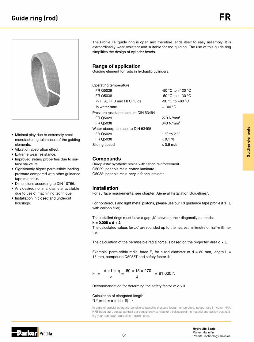
61
Hydraulic SealsParker HannifinPrädifa Technology Division
Gui
din
g e
lem
ents
Guide ring (rod) FR
The Profile FR guide ring is open and therefore lends itself to easy assembly. It is extraordinarily wear-resistant and suitable for rod guiding. The use of this guide ring simplifies the design of cylinder heads.
• Minimal play due to extremely small manufacturing tolerances of the guiding elements.
• Vibration absorption effect.• Extreme wear resistance.• Improved sliding properties due to sur-
face structure.• Significantly higher permissible loading
pressure compared with other guidance tape materials.
• Dimensions according to DIN 10766.• Any desired nominal diameter available
due to use of machining technique.• Installation in closed and undercut
housings.
Range of applicationGuiding element for rods in hydraulic cylinders.
Operating temperature FR Q5029 FR Q5038
-50 °C to +120 °C-50 °C to +130 °C
in HFA, HFB and HFC fluids -30 °C to +80 °C
in water max. + 100 °C
Pressure resistance acc. to DIN 53454 FR Q5029 FR Q5038
270 N/mm²340 N/mm²
Water absorption acc. to DIN 53495 FR Q5029 FR Q5038
1 % to 2 %< 0.1 %
Sliding speed ≤ 0.5 m/s
CompoundsDuroplastic synthetic resins with fabric reinforcement.Q5029: phenole resin-cotton laminate.Q5038: phenole resin-acrylic fabric laminate.
InstallationFor surface requirements, see chapter „General Installation Guidelines“.
For nonferrous and light metal pistons, please use our F3 guidance tape profile (PTFE with carbon filler).
The installed rings must have a gap „k“ between their diagonally cut ends:k = 0.008 x d + 2The calculated values for „k“ are rounded up to the nearest millimetre or half-millime-tre.
The calculation of the permissible radial force is based on the projected area d × L.
Example: permissible radial force FR for a rod diameter of d = 80 mm, length L = 15 mm, compound Q5038T and safety factor 4:
81 000 N80 × 15 × 270 d × L × q
FR = = =ν 4
Recommendation for determing the safety factor ν: ν > 3
Calculation of elongated length“U“ (rod) = π × (d + S) - k
In case of special operating conditions (specific pressure loads, temperature, speed, use in water, HFA, HFB fluids etc.), please contact our consultancy service for a selection of the material and design best suit-ing your particular application requirements.

62
Hydraulic SealsParker HannifinPrädifa Technology Division
Gui
din
g e
lem
ents
Guide ring (rod) FR
R ≤ 0,2
R ≤ 0
,2
kk
L+0,2
Ø d
Ø D
H9
Ø d
1D11
Ø d
f7
For surface finish, lead in chamfer and other installation dimensions see „General installation guidelines“.
Ordering exampleGuide ring profile FR for a rod diameter of 63 mm.
Order code FR 6370 Q5029 (63 × 68 × 9,7)
FR Profile reference
6370 Dimension code
Q5029 or Q5038 Standard compound
d × D × L Nominal dimensions

63
Hydraulic SealsParker HannifinPrädifa Technology Division
Gui
din
g e
lem
ents
Guide ring (rod) FR
R ≤ 0,2
R ≤ 0
,2
kk
L+0,2
Ø d
Ø D
H9
Ø d
1D11
Ø d
f7
For surface finish, lead in chamfer and other installation dimensions see „General installation guidelines“.
Further sizes on request.
d, D, L, d1, Order code11 14 2.6 11.2 FR 1114 Q503812 15 3.6 12.2 FR 1215 Q503812 15.1 4 12.2 FR 1216 Q503814 17 2.5 14.2 FR 1417 Q503815 18 2.5 15.2 FR 1518 Q503815.5 19 3.6 15.7 FR 1519 Q503818 21 2.5 18.2 FR 1823 Q503818 21 6 18.2 FR 1821 Q503820 25 4 20.2 FR 2025 Q503820 25 5.6 20.2 FR 2005 Q503820 25 9.7 20.2 FR 2007 Q503820 26 5.1 20.2 FR 2008 Q503822 25 2.5 22.2 FR 2225 Q503822 25.1 4 22.2 FR 2224 Q503822 26 5.6 22.2 FR 2226 Q503825 30 5.6 25.2 FR 2506 Q503825 30 9.7 25.2 FR 2507 Q503825.4 28.5 4 25.6 FR 2528 Q503827 32 5.6 27.2 FR 2702 Q503828 33 5.6 28.2 FR 2823 Q503828 33 9.7 28.2 FR 2833 Q503830 33 2.5 30.2 FR 3033 Q503830 34 9.7 30.2 FR 3034 Q503830 35 4 30.2 FR 3002 Q503830 35 5.6 30.2 FR 3001 Q503830 35 9.7 30.2 FR 3003 Q503830 36 5.1 30.2 FR 3036 Q503832 37 5.6 32.3 FR 3205 Q503832 37 9.7 32.3 FR 3209 Q503834 40 5.1 34.3 FR 3440 Q503835 40 4 35.3 FR 3505 Q503835 40 5.6 35.3 FR 3506 Q503835 40 9.7 35.3 FR 3507 Q503835 45 15 35.3 FR 3528 Q5038
d, D, L, d1, Order code36 41 5.6 36.3 FR 3618 Q503836 41 9.7 36.3 FR 3620 Q503837 42 5.6 37.3 FR 3742 Q503838 41 2.5 38.3 FR 3841 Q503840 45 5.6 40.4 FR 4004 Q503840 45 9.7 40.4 FR 4006 Q503840 45 15 40.4 FR 4010 Q503840 45.1 5.6 40.4 FR 4047 Q503840 46 9.8 40.4 FR 4046 Q503844 50 5.1 44.4 FR 4451 Q503845 48 2.5 45.4 FR 4548 Q503845 50 5.6 45.4 FR 4504 Q503845 50 6.3 45.4 FR 4506 Q503845 50 9.7 45.4 FR 4505 Q503845 50 15 45.4 FR 4508 Q503848 53 9.7 48.4 FR 4853 Q503850 55 5.6 50.4 FR 5015 Q503850 55 6.3 50.4 FR 5063 Q503850 55 9.7 50.4 FR 5018 Q503850 55 20 50.4 FR 5019 Q503850.8 55.8 16 51.2 FR 5079 Q503850.8 55.8 25 51.2 FR 5080 Q503853 58 9.7 53.4 FR 5309 Q503855 58 4 55.4 FR 5558 Q503855 60 5.6 55.4 FR 5505 Q503855 60 6.3 55.4 FR 5560 Q503855 60 9.7 55.4 FR 5507 Q503855 60 15 55.4 FR 5510 Q503857 60 4 57.4 FR 5760 Q503858 63 5.6 58.4 FR 5808 Q503858 63 6.3 58.4 FR 5680 Q503858 63 9.7 58.4 FR 5805 Q503860 65 5.6 60.5 FR 6006 Q503860 65 6.3 60.5 FR 6065 Q5038

64
Hydraulic SealsParker HannifinPrädifa Technology Division
Gui
din
g e
lem
ents
Guide ring (rod) FR
R ≤ 0,2
R ≤ 0
,2
kk
L+0,2
Ø d
Ø D
H9
Ø d
1D11
Ø d
f7
For surface finish, lead in chamfer and other installation dimensions see „General installation guidelines“.
Further sizes on request.
d, D, L, d1, Order code60 65 9.7 60.5 FR 6005 Q503860 65 15 60.5 FR 6010 Q503860 65 25 60.5 FR 6012 Q503863 68 5.6 63.5 FR 6305 Q503863 68 6.3 63.5 FR 6368 Q503863 68 9.7 63.5 FR 6370 Q503863 68 15 63.5 FR 6315 Q503863 68 25 63.5 FR 6368 Q503865 70 5.6 65.5 FR 6501 Q503865 70 9.7 65.5 FR 6503 Q503865 70 15 65.5 FR 6506 Q503870 75 6.3 70.5 FR 7000 Q503870 75 9.7 70.5 FR 7005 Q503870 75 15 70.5 FR 7004 Q503875 80 5.6 75.5 FR 7503 Q503875 80 6.3 75.5 FR 7504 Q503875 80 9.7 75.5 FR 7506 Q503875 80 15 75.5 FR 7505 Q503879 84 15 79.5 FR 7984 Q503880 84 15 80.5 FR 8009 Q503880 85 5.6 80.5 FR 8085 Q503880 85 9.7 80.5 FR 8010 Q503880 85 15 80.5 FR 8012 Q503880 85 25 80.5 FR 8014 Q503883 88 9.7 83.5 FR 8388 Q503885 90 9.7 85.5 FR 8509 Q503885 90 15 85.5 FR 8515 Q503885 90 25 85.5 FR 8525 Q503885 95 25 85.5 FR 8510 Q503886 90 10 86.5 FR 8690 Q503890 95 9.7 90.5 FR 9094 Q503890 95 15 90.5 FR 9095 Q503890 95 20 90.5 FR 9020 Q503890 95 25 90.5 FR 9025 Q5038
d, D, L, d1, Order code90 95 30 90.5 FR 9030 Q503890 100 15 90.5 FR 9010 Q503895 100 9.7 95.6 FR 9510 Q503895 100 15 95.6 FR 9511 Q5038
100 105 5.6 100.6 FR A003 Q5038100 105 9.7 100.6 FR A004 Q5038100 105 15 100.6 FR A005 Q5038100 105 20 100.6 FR A006 Q5038100 105 25 100.6 FR A025 Q5038100 110 25 100.6 FR A027 Q5038105 110 9.7 105.6 FR A505 Q5038105 110 15 105.6 FR A511 Q5038105 110 20 105.6 FR A520 Q5038105 110 25 105.6 FR A510 Q5038110 115 9.7 110.6 FR B008 Q5038110 115 15 110.6 FR B009 Q5038110 115 25 110.6 FR B011 Q5038110 120 15 110.6 FR B007 Q5038110 125 25 110.6 FR B025 Q5038114 120 10 114.6 FR B040 Q5038115 120 9.7 115.6 FR B051 Q5038115 120 15 115.6 FR B053 Q5038115 120 25 115.6 FR B525 Q5038120 125 9.7 120.6 FR C051 Q5038120 125 15 120.6 FR C052 Q5038120 125 25 120.6 FR C026 Q5038125 130 9.7 125.6 FR C053 Q5038125 130 15 125.6 FR C055 Q5038125 130 25 125.6 FR C030 Q5038126 130 15 126.6 FR C130 Q5038130 135 15 130.6 FR D005 Q5038135 140 9.7 135.6 FR D050 Q5038135 140 15 135.6 FR D051 Q5038135 140 25 135.6 FR D052 Q5038

65
Hydraulic SealsParker HannifinPrädifa Technology Division
Gui
din
g e
lem
ents
Guide ring (rod) FR
R ≤ 0,2
R ≤ 0
,2
kk
L+0,2
Ø d
Ø D
H9
Ø d
1D11
Ø d
f7
For surface finish, lead in chamfer and other installation dimensions see „General installation guidelines“.
Further sizes on request.
d, D, L, d1, Order code136 140 15 136.6 FR D140 Q5038140 145 9.7 140.7 FR E031 Q5038140 145 15 140.7 FR E038 Q5038140 145 25 140.7 FR E032 Q5038145 150 9.7 145.7 FR E047 Q5038145 150 15 145.7 FR E050 Q5038150 155 9.7 150.7 FR F009 Q5038150 155 15 150.7 FR F050 Q5038150 155 25 150.7 FR F015 Q5038155 160 9.7 155.7 FR F051 Q5038155 160 15 155.7 FR F052 Q5038155 160 25 155.7 FR F055 Q5038160 165 9.7 160.7 FR G008 Q5038160 165 15 160.7 FR G007 Q5038160 165 25 160.7 FR G025 Q5038165 170 9.7 165.7 FR G565 Q5038165 170 15 165.7 FR G570 Q5038170 175 9.7 170.7 FR H024 Q5038170 175 15 170.7 FR H015 Q5038170 175 25 170.7 FR H025 Q5038175 180 9.7 175.7 FR H050 Q5038175 180 15 175.7 FR H051 Q5038175 180 25 175.7 FR H053 Q5038176 181 38 176.7 FR H062 Q5038180 185 15 180.7 FR J019 Q5038180 185 25 180.7 FR J020 Q5038180 185 38 180.7 FR J021 Q5038185 190 25 185.7 FR J525 Q5038186 190 15 186.7 FR J060 Q5038190 195 15 190.7 FR K012 Q5038190 200 15 190.7 FR K014 Q5038192 200 40 192.7 FR K240 Q5038195 200 9.7 195.7 FR K049 Q5038195 200 15 195.7 FR K052 Q5038
d, D, L, d1, Order code195 200 25 195.7 FR K051 Q5038200 205 15 200.7 FR L004 Q5038200 205 25 200.7 FR L025 Q5038202 210 25 205.7 FR L050 Q5038205 210 25 205.7 FR L065 Q5038205 210 25 205.7 FR L075 Q5038210 215 25 210.7 FR L509 Q5038215 220 15 215.7 FR L520 Q5038215 220 20 215.7 FR L524 Q5038215 220 25 215.7 FR L525 Q5038220 225 9.7 220.7 FR M004 Q5038220 225 15 220.7 FR M005 Q5038220 225 25 220.7 FR M009 Q5038220 228 25 220.7 FR M012 Q5038220 230 25 220.7 FR M030 Q5038222 227 15 222.7 FR M070 Q5038225 230 15 225.7 FR M125 Q5038230 235 25 230.7 FR M525 Q5038235 240 9.7 235.7 FR M554 Q5038235 240 15 235.7 FR M550 Q5038235 240 25 235.7 FR M560 Q5038235 240 35 235.7 FR M558 Q5038235 250 25 235.7 FR M600 Q5038245 250 15 245.7 FR N042 Q5038245 250 20 245.7 FR N043 Q5038245 250 25 245.7 FR N045 Q5038250 255 15 250.7 FR N520 Q5038250 255 25 250.7 FR N525 Q5038250 258 25 250.7 FR N530 Q5038260 265 15 260.7 FR O008 Q5038260 265 25 260.7 FR O010 Q5038260 266 30 260.7 FR O011 Q5038265 270 15 265.7 FR O515 Q5038265 270 25 265.7 FR O520 Q5038

66
Hydraulic SealsParker HannifinPrädifa Technology Division
Gui
din
g e
lem
ents
Guide ring (rod) FR
R ≤ 0,2
R ≤ 0
,2
kk
L+0,2
Ø d
Ø D
H9
Ø d
1D11
Ø d
f7
For surface finish, lead in chamfer and other installation dimensions see „General installation guidelines“.
Further sizes on request.
d, D, L, d1, Order code270 275 25 270.7 FR O706 Q5038275 280 15 275.8 FR O715 Q5038275 280 20 275.8 FR O720 Q5038275 280 25 275.8 FR O725 Q5038280 270 23 280.8 FR P023 Q5038280 285 15 280.8 FR P015 Q5038280 285 25 280.8 FR P024 Q5038280 290 25 280.8 FR P025 Q5038295 300 15 295.8 FR P551 Q5038295 300 24 295.8 FR P550 Q5038300 305 25 301 FR Q005 Q5038305 310 15 306 FR Q002 Q5038310 315 25 311 FR Q010 Q5038312 320 25 313 FR Q130 Q5038314 320 30 315 FR Q011 Q5038315 320 15 316 FR Q014 Q5038315 320 25 316 FR Q015 Q5038320 325 15 321 FR Q215 Q5038320 325 25 321 FR Q217 Q5038325 330 20 326 FR Q230 Q5038325 330 25 326 FR Q233 Q5038330 335 15 331 FR Q335 Q5038330 335 25 331 FR Q336 Q5038335 340 15 336 FR Q334 Q5038345 350 25 346 FR Q425 Q5038350 355 15 351 FR Q050 Q5038350 355 15 351 FR Q515 Q5038350 355 25 351 FR Q051 Q5038350 360 25 351 FR Q060 Q5038355 360 20 356 FR Q552 Q5038355 360 40 356 FR Q555 Q5038375 380 15 376 FR Q715 Q5038375 380 25 376 FR Q725 Q5038390 395 25 391 FR Q900 Q5038
d, D, L, d1, Order code440 445 15 441 FR R024 Q5038442 450 25 443 FR R410 Q5038445 450 25 446 FR R025 Q5038460 465 9.5 461 FR R465 Q5038465 470 15 466 FR R615 Q5038495 500 15 496 FR R915 Q5038575 580 25 576 FR S075 Q5038600 605 25 601 FR S610 Q5038

67
Hydraulic SealsParker HannifinPrädifa Technology Division
Gui
din
g e
lem
ents
Guide ring (piston) FK
The Profile FK guide ring is open and therefore lends itself to easy assembly. It is ex-traordinarily wear-resistant and suitable for piston guiding. The use of this guide ring simplifies the design of pistons.
• Minimal play due to extremely small manufacturing tolerances of the guiding elements.
• Vibration absorption effect.• Extreme wear resistance.• Improved sliding properties due to sur-
face structure.• Easy snap assembly on a single-part
piston.• Significantly higher permissible loading
pressure compared with other guidance tape materials.
• Dimensions according to DIN 10766.• Also available as bulk material.• Any desired nominal diameter available
due to use of machining technique.• Installation in closed and undercut
housings.
Range of applicationGuiding element for pistons and piston rods in hydraulic cylinders.
Operating temperature FKS525Q5038 FK Q5029
-50 °C to +130 °C-50 °C to +120 °C
in HFA, HFB and HFC fluids -30 °C to +80 °C
in water max. + 100 °C
Pressure resistance acc. to DIN 53454 FKS525Q5038 FK Q5029
340 N/mm²270 N/mm²
Water absorption acc. to DIN 53495 FKS525Q5038 FK Q5029
< 0.1 %1 % to 2 %
Sliding speed ≤ 0.5 m/s
CompoundsDuroplastic synthetic resins with fabric reinforcement.Q5029: phenole resin-cotton laminate.Q5038: phenole resin-acrylic fabric laminate.
InstallationFor surface requirements, see chapter „General Installation Guidelines“.
For nonferrous and light metal pistons, please use our F3 guidance tape profile (PTFE with carbon filler).
The installed rings must have a gap „k“ between their diagonally cut ends:k = 0.008 x d + 2The calculated values for „k“ are rounded up to the nearest millimetre or half-millime-tre.
The calculation of the permissible radial force is based on the projected area D × L.
Example: permissible radial force FR for a cylinder diameter of D = 80 mm, length L = 15 mm, compound Q5038T and safety factor 4:
81 000 N80 × 15 × 270 D × L × q
FR = = =ν 4
Recommendation for determing the safety factor ν: ν > 3
Calculation of elongated length“U“ (piston) = π × (D - S) - k
In case of special operating conditions (specific pressure loads, temperature, speed, use in water, HFA, HFB fluids etc.), please contact our consultancy service for a selection of the material and design best suit-ing your particular application requirements.
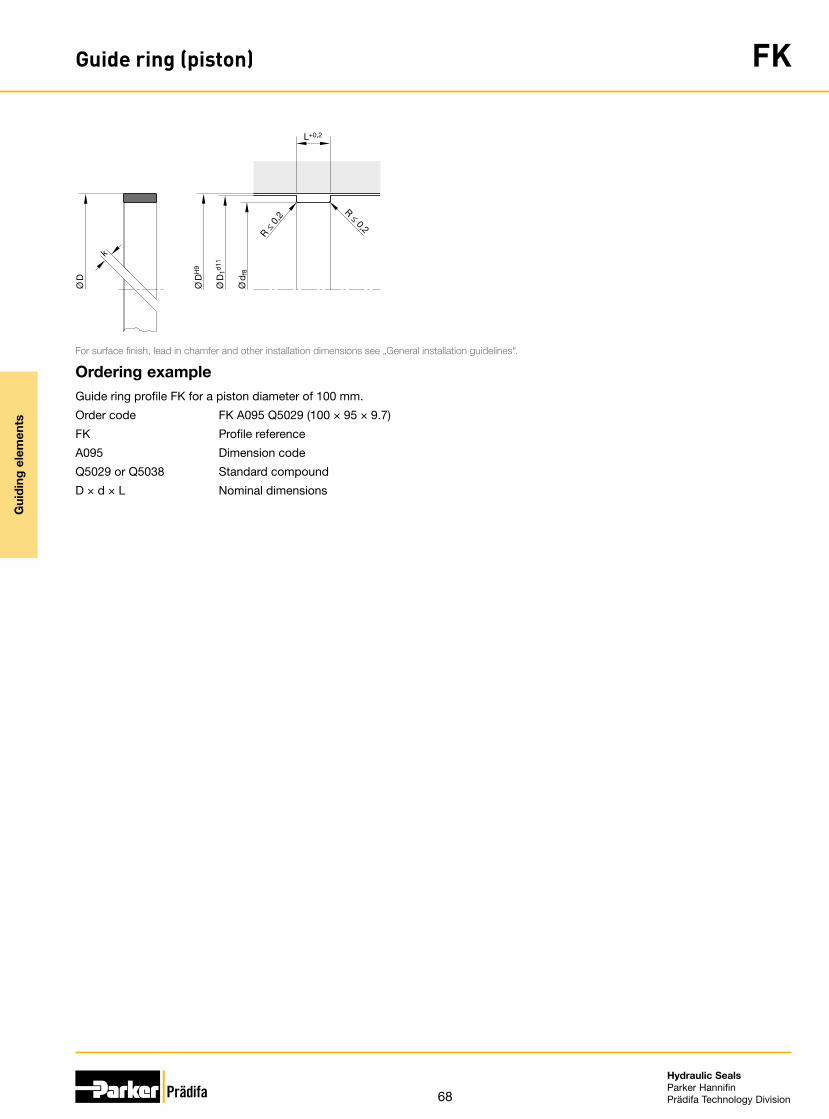
68
Hydraulic SealsParker HannifinPrädifa Technology Division
Gui
din
g e
lem
ents
Guide ring (piston) FK
R ≤ 0,2
R ≤ 0
,2
k
L+0,2
Ø D
Ø D
H9
Ø D
1d11
Ø d
f8
For surface finish, lead in chamfer and other installation dimensions see „General installation guidelines“.
Ordering exampleGuide ring profile FK for a piston diameter of 100 mm.
Order code FK A095 Q5029 (100 × 95 × 9.7)
FK Profile reference
A095 Dimension code
Q5029 or Q5038 Standard compound
D × d × L Nominal dimensions

69
Hydraulic SealsParker HannifinPrädifa Technology Division
Gui
din
g e
lem
ents
Guide ring (piston) FK
R ≤ 0,2
R ≤ 0
,2
k
L+0,2
Ø D
Ø D
H9
Ø D
1d11
Ø d
f8
For surface finish, lead in chamfer and other installation dimensions see „General installation guidelines“.
Further sizes on request.
D, d, L, D1, Order code25 20 5.6 24.8 FK 2520 Q503825 20 9.7 24.8 FK 2597 Q503828 23 6.3 27.8 FK 2923 Q503832 27 5.6 31.8 FK 3227 Q503832 27 9.7 31.8 FK 3228 Q503835 30 5.6 34.8 FK 3530 Q503835 30 9.7 34.8 FK 3597 Q503836 31 5.6 35.8 FK 3631 Q503840 35 5.6 39.7 FK 4035 Q503840 35 9.7 39.7 FK 4097 Q503842 37 5.6 41.7 FK 4237 Q503845 40 5.6 44.6 FK 4540 Q503845 40 9.7 44.6 FK 4597 Q503850 45 5.6 49.6 FK 5043 Q503850 45 9.7 49.6 FK 5045 Q503855 50 5.6 54.6 FK 5550 Q503855 50 9.7 54.6 FK 5597 Q503860 55 5.6 59.6 FK 6055 Q503860 55 9.7 59.6 FK 6097 Q503863 58 5.6 62.6 FK 5356 Q503863 58 6.3 62.6 FK 6359 Q503863 58 9.7 62.6 FK 6397 Q503865 60 5.6 64.5 FK 6561 Q503865 60 6.3 64.5 FK 6560 Q503865 60 9.7 64.5 FK 6597 Q503870 65 5.6 69.5 FK 7030 Q503870 65 6.3 69.5 FK 7065 Q503870 65 9.7 69.5 FK 7097 Q503870 65 15 69.5 FK 7015 Q503875 70 5.6 74.5 FK 7569 Q503875 70 9.7 74.5 FK 7570 Q503875 70 15 74.5 FK 7515 Q503880 75 6.3 79.5 FK 8075 Q503880 75 9.7 79.5 FK 8076 Q5038
D, d, L, D1, Order code80 75 15 79.5 FK 8015 Q503880 75 25 79.5 FK 8077 Q503885 80 6.3 84.5 FK 8580 Q503885 80 9.7 84.5 FK 8581 Q503885 80 15 84.5 FK 8515 Q503890 85 5.6 89.5 FK 9084 Q503890 85 9.7 89.5 FK 9086 Q503890 85 15 89.5 FK 9015 Q503890 85 25 89.5 FK 9085 Q503895 90 5.6 94.5 FK 9591 Q503895 90 9.7 94.5 FK 9590 Q503895 90 15 94.5 FK 9515 Q5038
100 95 5.6 99.4 FK A094 Q5038100 95 9.7 99.4 FK A095 Q5038100 95 15 99.4 FK 9513 Q5038105 100 9.7 104.4 FK A500 Q5038105 100 15 104.4 FK A515 Q038110 105 9.7 109.4 FK B005 Q5038110 105 15 109.4 FK B015 Q5038115 110 9.7 114.4 FK B510 Q5038115 110 15 114.4 FK B110 Q5038120 115 9.7 119.4 FK C115 Q5038120 115 15 119.4 FK C120 Q5038125 120 9.7 124.4 FK C520 Q5038125 120 15 124.4 FK C525 Q5038130 125 9.7 129.4 FK D026 Q5038130 125 15 129.4 FK D045 Q5038140 135 9.7 139.4 FK E035 Q5038140 135 15 139.4 FK E015 Q5038145 140 9.7 144.3 FK E540 Q5038145 140 15 144.3 FK E550 Q5038150 145 9.7 149.3 FK F045 Q5038150 145 15 149.3 FK F050 Q5038155 150 9.7 154.3 FK F550 Q5038

70
Hydraulic SealsParker HannifinPrädifa Technology Division
Gui
din
g e
lem
ents
Guide ring (piston) FK
R ≤ 0,2
R ≤ 0
,2
k
L+0,2
Ø D
Ø D
H9
Ø D
1d11
Ø d
f8
For surface finish, lead in chamfer and other installation dimensions see „General installation guidelines“.
Further sizes on request.
D, d, L, D1, Order code155 150 15 154.3 FK F551 Q5038155 150 25 154.3 FK F525 Q5038160 155 9.7 159.3 FK G055 Q5038160 155 15 159.3 FK G056 Q5038160 155 20 159.3 FK G025 Q5038165 160 9.7 164.3 FK G560 Q5038165 160 15 164.3 FK G561 Q5038165 160 25 164.3 FK G525 Q5038170 165 9.7 169.3 FK H065 Q5038170 165 15 169.3 FK H066 Q5038170 165 25 169.3 FK H075 Q5038175 170 9.7 174.3 FK H570 Q5038175 170 15 174.3 FK H571 Q5038175 170 25 174.3 FK H525 Q5038180 175 9.7 179.3 FK J075 Q5038180 175 15 179.3 FK J175 Q5038180 175 25 179.3 FK J025 Q5038190 185 9.7 189.3 FK K165 Q5038190 185 15 189.3 FK K175 Q5038190 185 25 189.3 FK K185 Q5038200 195 9.7 199.3 FK L095 Q5038200 195 15 199.3 FK L096 Q5038200 195 25 199.3 FK L195 Q5038205 200 15 204.3 FK L500 Q5038205 200 25 204.3 FK L525 Q5038210 205 15 209.3 FK L005 Q5038210 205 25 209.3 FK L026 Q5038215 210 15 214.3 FK L520 Q5038215 210 25 214.3 FK L526 Q5038220 215 15 219.3 FK M015 Q5038220 215 25 219.3 FK M016 Q5038225 220 15 224.3 FK M520 Q5038225 220 25 224.3 FK M525 Q5038230 225 15 229.3 FK M025 Q5038
D, d, L, D1, Order code230 225 25 229.3 FK M225 Q5038240 235 15 239.3 FK N036 Q5038240 235 25 239.3 FK N050 Q5038250 245 15 249.3 FK N046 Q5038250 245 25 249.3 FK N245 Q5038255 250 15 254.3 FK N550 Q5038255 250 25 254.3 FK N525 Q5038260 255 15 259.3 FK O015 Q5038260 255 25 259.3 FK O025 Q5038265 260 15 264.3 FK O660 Q5038265 260 25 264.3 FK O625 Q5038270 265 15 269.3 FK O065 Q5038270 265 25 269.3 FK O075 Q5038275 270 15 274.3 FK O515 Q5038275 270 25 274.3 FK O525 Q5038280 275 15 279.2 FK P076 Q5038280 275 25 279.2 FK P025 Q5038285 280 15 284.2 FK P580 Q5038285 280 25 284.2 FK P525 Q5038290 285 15 289.2 FK P085 Q5038290 285 25 289.2 FK P095 Q5038300 295 15 299.2 FK Q001 Q5038300 295 25 299.2 FK Q000 Q5038310 305 15 309 FK Q010 Q5038310 305 25 309 FK Q025 Q5038320 315 15 319 FK Q020 Q5038320 315 25 319 FK Q021 Q5038330 325 15 329 FK Q015 Q5038330 325 25 329 FK Q030 Q5038350 345 15 349 FK Q315 Q5038350 345 25 349 FK Q346 Q5038380 375 15 379 FK Q070 Q5038380 375 25 379 FK Q080 Q5038400 395 15 399 FK R015 Q5038
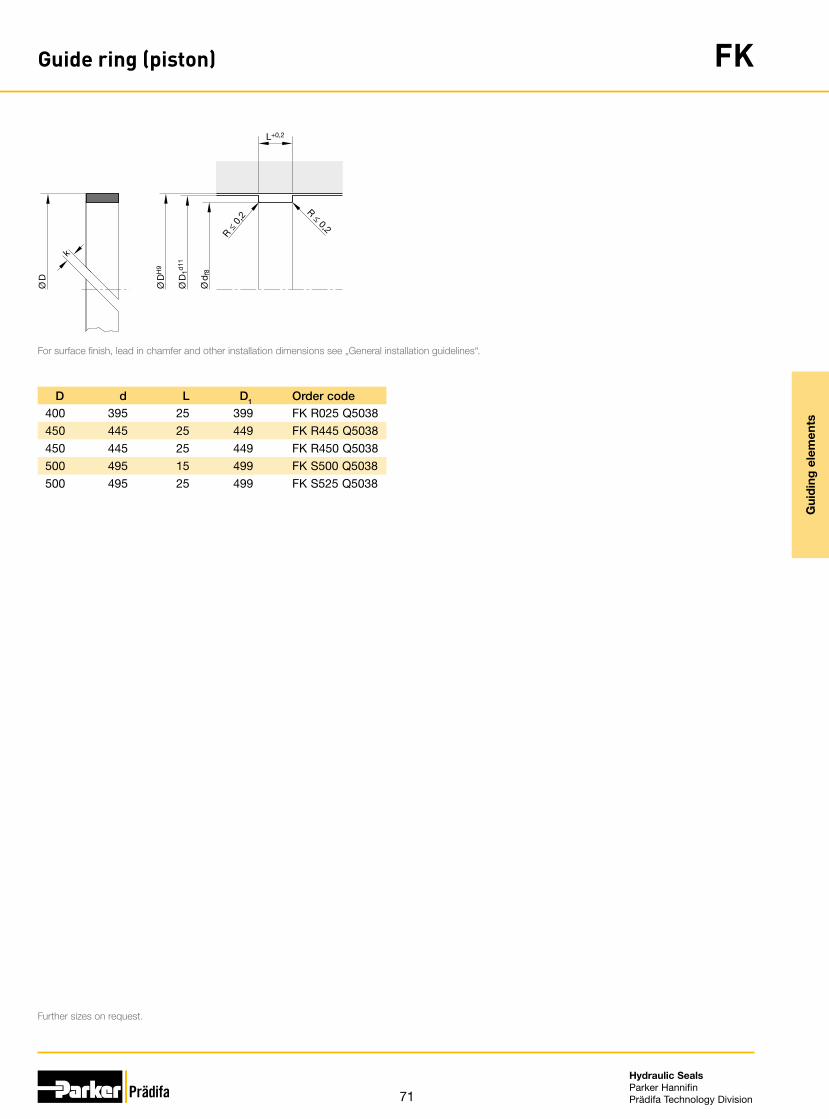
71
Hydraulic SealsParker HannifinPrädifa Technology Division
Gui
din
g e
lem
ents
Guide ring (piston) FK
R ≤ 0,2
R ≤ 0
,2
k
L+0,2
Ø D
Ø D
H9
Ø D
1d11
Ø d
f8
For surface finish, lead in chamfer and other installation dimensions see „General installation guidelines“.
Further sizes on request.
D, d, L, D1, Order code400 395 25 399 FK R025 Q5038450 445 25 449 FK R445 Q5038450 445 25 449 FK R450 Q5038500 495 15 499 FK S500 Q5038500 495 25 499 FK S525 Q5038

72
Hydraulic SealsParker HannifinPrädifa Technology Division
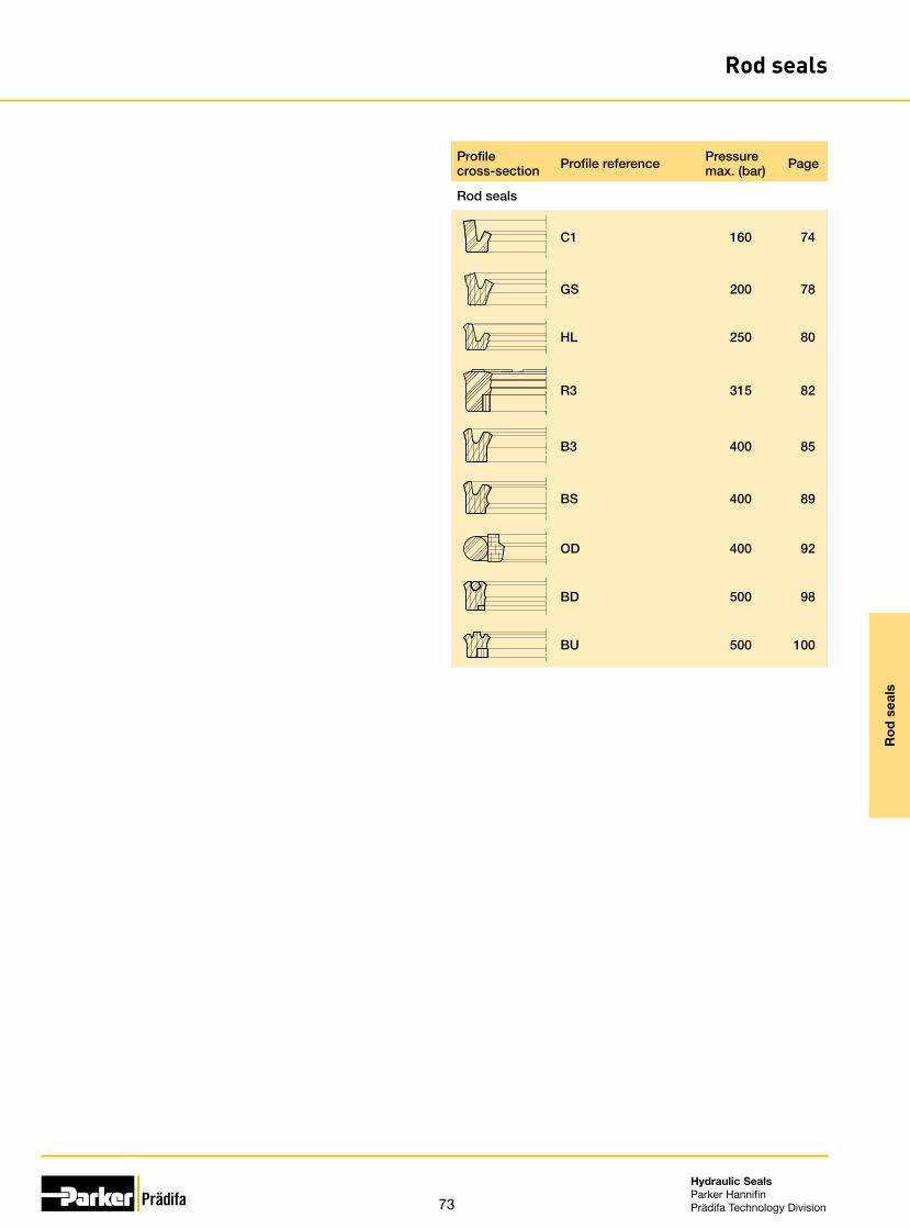
73
Hydraulic SealsParker HannifinPrädifa Technology Division
Ro
d s
eals
Rod seals
Profile cross-section Profile reference Pressure
max. (bar) Page
Rod seals
C1 160 74
GS 200 78
HL 250 80
R3 315 82
B3 400 85
BS 400 89
OD 400 92
BD 500 98
BU 500 100

74
Hydraulic SealsParker HannifinPrädifa Technology Division
Ro
d s
eals
Rod seal C1
The profile C1 rod seal meets the requirements of the manufacturers of hydraulic and pneumatic equipment for seals with the smallest possible housings. Although cross-sections and heights are very small, the sealing performance is excellent.
Extremely low friction is experienced because of the short contact of the sealing sur-face area. Back-up rings or brackets are not required because of the special design.
Use in pneumatic equipment is only possible when consistent supply of lubricant such as oiled air is assured. For installation in non-lubricated pneumatic systems (dry air) we recommend our profile E5 which fits into the same housings.
• Good wear resistance.• Easy installation.• High temperature resistance in case of
suitable compound selection.• Excellent media resistance in case of
suitable compound selection.• Suitable compounds available for
special requirements of the chemical process industry.
• Suitable compounds available for spe-cial requirements of the food processing industry.
• Installation in closed and undercut housings.
Range of applicationThe profile C1 rod seal is especially recommended for plungers, piston rods, stems and valve lifters as well as for slowly operating pneumatic rotors (v ≤ 0,2 m/s).
Operating pressure 1)
Hydraulics ≤ 160 bar
Pneumatics ≤ 16 bar
Rotary transmissions ≤ 20 bar
Operating temperature
Hydraulics -35 °C to +100 °C
Pneumatics -35 °C to +80 °C
Sliding speed
Hydraulics ≤ 0.5 m/s
Pneumatics ≤ 1 m/s
Rotary transmissions ≤ 0.2 m/s
Recommendation for rotary transmissions: P × v ≤ 3(Definition see catalogue „Hydraulic Seals“, chapter „Rotary Seals“, introduction).
1) Dependent upon cross-section and compound.
CompoundsStandard: N3571, NBR compound (≈ 70 Shore A).For low temperatures: N8602, NBR compound (≈ 70 Shore A).For high temperatures: V3664, FKM compound (≈ 85 Shore A).
InstallationThe profile C1 rod seals are manufactured over-sized on the external diameters in relation to the nominal dimensions. This ensures the required tight fit. Only after instal-lation the sealing lip diameter will show the desired dimensions. Profile C1 can easily be snapped into the grooves.When choosing a seal for a particular diameter, it is best to select the one with the largest possible cross-section.
Note: For nominal diameters ≤ 25 mm an open housing is recommended, according to the seals cross-section and the position of the groove (stuffing box installation).
In case of special operating conditions (specific pressure loads, temperature, speed, use in water, HFA, HFB fluids etc.), please contact our consultancy service for a selection of the material and design best suit-ing your particular application requirements.

75
Hydraulic SealsParker HannifinPrädifa Technology Division
Ro
d s
eals
Rod seal C1
R ≤ 0,2
R ≤ 0,2
Ø D
H9
(Pne
u. e9
)
H8
H11
Ø d
f7
Ø D
Ø d
L+ 0,2
H
e
R ≤ 0,2
R ≤ 0,2
For surface finish, lead in chamfer and other installation dimensions see „General installation guidelines“.
„e“ see chapter „Maximum gap allowance“.
Further sizes on request.
d, D, H, L, Order code2 7 3.5 4 C1 0003 N35713 7 3 3.5 C1 0005 N35713 9 4.5 5 C1 0009 N35713 10 5 5.5 C1 0011 N35714 8 3 3.5 C1 0013 N35714 9 3.5 4 C1 0016 N35714 10 4.2 4.7 C1 0019 N35714 12 4.5 5 C1 0022 N35714 12 5.5 6 C1 0024 N35714 14 5.8 6.3 C1 0028 N35714.5 8 3 3.5 C1 0032 N35715 9 2.5 3 C1 0035 N35715 10 4 4.5 C1 0038 N35715 12 4.5 5 C1 0041 N35716 10 3 3.5 C1 0055 N35716 12 4.2 4.7 C1 0058 N35716 13 5 5.5 C1 0059 N35716 15 7 7.5 C1 0062 N35716 16 5 5.5 C1 0065 N35717 13 4 4.5 C1 0070 N35718 14 4 4.5 C1 0074 N35718 14.5 4.5 5 C1 0077 N35718 16 5.5 6 C1 0080 N35718 18 8 8.5 C1 0083 N35719 14 3.5 4 C1 0087 N35719.3 14 3 3.5 C1 0090 N35719.5 18.5 7 7.5 C1 0094 N3571
10 13.6 2.3 2.7 C1 1002 N357110 15 3.5 4 C1 1005 N357110 16 4.5 5 C1 1008 N357110 16 6 6.5 C1 1011 N357110 18 5.5 6 C1 1015 N357110 20 7 7.5 C1 1018 N357110.4 15.2 3.5 4 C1 1020 N3571
d, D, H, L, Order code11 17 4 4.5 C1 1022 N357111 18 4.5 5 C1 1025 N357112 18.5 4.5 5 C1 1028 N357112 19 4.5 5 C1 1030 N357112 20 5.5 6 C1 1033 N357112.75 19.2 3.8 4.3 C1 1035 N357113 17.5 2.8 3.3 C1 1036 N357113.8 22 5.5 6 C1 1037 N357114 19 3.5 4 C1 1039 N357114 20 4.8 5.3 C1 1040 N357114 22 5.5 6 C1 1041 N357114 25 8 8.5 C1 1042 N357115 22 5 5.5 C1 1044 N357115.8 24 5.5 6 C1 1047 N357116 22.5 4.5 5 C1 1049 N357116 23 5.5 6 C1 1051 N357116 23.5 5.5 6 C1 1052 N357116 24 5.5 6 C1 1053 N357116 26 7 7.5 C1 1056 N357116 27 7.5 8 C1 1058 N357117 25 5.5 6 C1 1060 N357118 25 4.5 5 C1 1062 N357118 25 5.5 6 C1 1063 N357118 26 5.5 6 C1 1066 N357118 30 8.5 9.5 C1 1070 N357118.5 25.5 5.5 6 C1 1074 N357119 25 5 5.5 C1 1079 N357120 26 4 4.5 C1 2003 N357120 26 4.8 5.3 C1 2005 N357120 28 5.5 6 C1 2009 N357120 28 8 8.5 C1 2013 N357120 30 7 7.5 C1 2020 N357120 32 7 7.5 C1 2022 N357122 29 5.5 6 C1 2025 N3571

76
Hydraulic SealsParker HannifinPrädifa Technology Division
Ro
d s
eals
Rod seal C1
R ≤ 0,2
R ≤ 0,2
Ø D
H9
(Pne
u. e9
)
H8
H11
Ø d
f7
Ø D
Ø d
L+ 0,2
H
e
R ≤ 0,2
R ≤ 0,2
For surface finish, lead in chamfer and other installation dimensions see „General installation guidelines“.
„e“ see chapter „Maximum gap allowance“.
Further sizes on request.
d, D, H, L, Order code22 30 5.5 6 C1 2029 N357122 32 7 7.5 C1 2031 N357122 32 8 8.5 C1 2030 N357122 34 8.5 9.5 C1 2033 N357123 31 5.5 6 C1 2038 N357124 32 5.5 6 C1 2043 N357125 32 5.5 6 C1 2053 N357125 33 5.5 6 C1 2058 N357125 33 8 8.5 C1 2061 N357125 35 6 6.5 C1 2064 N357125 35 7 7.5 C1 2065 N357125 36 8 8.5 C1 2066 N357125 37 8.5 9.5 C1 2069 N357125 40 10 11 C1 2075 N357126 36 7 7.5 C1 2078 N357128 36 5.5 6 C1 2085 N357128 38 7 7.5 C1 2089 N357128 40 8.5 9.5 C1 2095 N357130 38 5.5 6 C1 3005 N357130 38 8 8.5 C1 3010 N357130 40 7 7.5 C1 3015 N357130 42 8 8.5 C1 3019 N357130 42 8.5 9.5 C1 3020 N357132 40 5.5 6 C1 3025 N357132 42 7 7.5 C1 3030 N357132 45 10 11 C1 3032 N357133 43 7 7.5 C1 3035 N357134 44 7 7.5 C1 3040 N357135 43 8 8.5 C1 3045 N357135 45 7 7.5 C1 3050 N357136 44 5.5 6 C1 3605 N357136 46 7 7.5 C1 3055 N357136 50 10 11 C1 3057 N357137 47 7 7.5 C1 3059 N3571
d, D, H, L, Order code38 48 7 7.5 C1 3060 N357140 48 8 8.5 C1 4010 N357140 50 7 7.5 C1 4015 N357140 52 8.5 9.5 C1 4020 N357142 52 7 7.5 C1 4025 N357144 54 7 7.5 C1 4030 N357145 53 5.5 6 C1 4505 N357145 55 7 7.5 C1 4035 N357145 60 10 11 C1 4040 N357146 56 7 7.5 C1 4046 N357147 57 7 7.5 C1 4055 N357148 58 7 7.5 C1 4060 N357150 58 8 8.5 C1 5005 N357150 60 7 7.5 C1 5010 N357150 63 8.5 9.5 C1 5015 N357150 63 12 13 C1 5017 N357150 66 11 12 C1 5020 N357154 64 7 7.5 C1 5035 N357155 65 7 7.5 C1 5040 N357156 66 7 7.5 C1 5043 N357156 70 12 13 C1 5044 N357157 67 7 7.5 C1 5053 N357158 68 7 7.5 C1 5058 N357159 71 7.5 8 C1 5085 N357160 72 8.5 9.5 C1 6005 N357160 80 14 15 C1 6010 N357163 73 7 7.5 C1 6025 N357163 75 8.5 9.5 C1 6035 N357163 78 8.5 9.5 C1 6036 N358463 80 16 17 C1 6037 N357164 76 7.5 8 C1 6040 N357165 77 8.5 9.5 C1 6055 N357168 80 8.5 9.5 C1 6070 N357170 82 8.5 9.5 C1 7003 N3571

77
Hydraulic SealsParker HannifinPrädifa Technology Division
Ro
d s
eals
Rod seal C1
R ≤ 0,2
R ≤ 0,2
Ø D
H9
(Pne
u. e9
)
H8
H11
Ø d
f7
Ø D
Ø d
L+ 0,2
H
e
R ≤ 0,2
R ≤ 0,2
For surface finish, lead in chamfer and other installation dimensions see „General installation guidelines“.
„e“ see chapter „Maximum gap allowance“.
Further sizes on request.
d, D, H, L, Order code75 87 8.5 9.5 C1 7020 N357175 95 14 15 C1 7030 N357180 90 7 7.5 C1 8010 N357180 92 7.5 8 C1 8013 N357180 92 8.5 9.5 C1 8015 N357180 100 14 15 C1 8025 N357185 97 8.5 9.5 C1 8040 N357185 100 10 11 C1 8045 N357188 100 8.5 9.5 C1 8070 N357190 102 6.5 7 C1 9014 N357190 102 8.5 9.5 C1 9015 N357190 110 16 17 C1 9018 N357195 107 8.5 9.5 C1 9035 N3571
100 110 7 7.5 C1 A010 N3571100 115 10 11 C1 A015 N3571105 120 10 11 C1 A051 N3571105 125 12 13 C1 A055 N3571110 125 10 11 C1 B015 N3571110 130 14 15 C1 B020 N3571115 130 10 11 C1 B040 N3571115 135 14 15 C1 B045 N3571120 135 10 11 C1 C015 N3571120 140 14 15 C1 C020 N3571125 140 10 11 C1 C035 N3571125 145 12 13 C1 C037 N3571130 145 10 11 C1 D015 N3571130 150 14 15 C1 D020 N3571135 150 10 11 C1 D035 N3571140 160 14 15 C1 E015 N3571142 157 10 11 C1 E035 N3571145 165 13 14 C1 E050 N3571150 170 14 15 C1 F020 N3571154 176 15.5 16.5 C1 F040 N3571155 170 10 11 C1 F053 N3571
d, D, H, L, Order code155 175 14 15 C1 F055 N3571160 180 14 15 C1 G015 N3571160 184 15 16 C1 G024 N3571166 188 15.5 16.5 C1 G040 N3571170 190 14 15 C1 H007 N3571170 194 15 16 C1 H010 N3571180 200 14 15 C1 J005 N3571185 210 17.5 18.5 C1 J025 N3571185 215 20 21 C1 J032 N3571190 210 14 15 C1 K010 N3571200 220 14 15 C1 L015 N3571200 230 15 16 C1 L025 N3571210 230 14 15 C1 L040 N3571220 250 20 21 C1 M017 N3571225 250 14 15 C1 M020 N3571235 265 21 22 C1 M030 N3571240 270 20 21 C1 N035 N3571260 280 14 15 C1 O007 N3571260 290 21 22 C1 O010 N3571280 310 20 21 C1 O031 N3571310 330 14 15 C1 Q001 N3571320 350 20 21 C1 Q050 N3571

78
Hydraulic SealsParker HannifinPrädifa Technology Division
Ro
d s
eals
Rod seal GS
The GS rod seal has been specifically developed for the challenging demands of gas spring applications. Apart from small housings, they include long service life and maximum gas tightness with low friction. These properties make the seal, in addition to its use in gas springs, suitable for applications in hydraulic and pneumatic equip-ment that involve the same demands. The short contact space of the sealing area guarantees low friction values. Back-up rings or retainers are not required due to the special shape. The seal can be used in both hydraulic and pneumatic systems with oiled air. The GS rod seal is compatible with the time-tested C1 seal profile and fits into the same housings.
• Good wear resistance.• Easy installation.• High temperature resistance in case of
suitable compound selection.• Excellent media resistance in case of
suitable compound selection.• Suitable compounds available for
special requirements of the chemical process industry.
• Suitable compounds available for spe-cial requirements of the food processing industry.
• Installation in closed and undercut housings.
Range of applicationThe GS rod seal is particularly well suited for gas springs, piston rods, spindles and valve lifters as well as for slow-running rotating unions (v ≤ 0.2 m/s).
Operating pressure 1)
Hydraulics ≤ 200 bar
Gas springs ≤ 200 bar
Rotary transmissions ≤ 20 bar
Operating temperature -35 °C to +90 °C
Sliding speed
Hydraulics ≤ 1 m/s
Gas springs ≤ 1 m/s
Rotary transmissions ≤ 0.2 m/s
Recommendation for rotary transmissions: P × v ≤ 3(For definition see catalogue „Hydraulic Seals“, chapter „Rotary Seals“, introduction).1) Dependent upon cross-section and compound.
CompoundsStandard: P5008, TPU (≈ 94 Shore A).For high pressures (> 200 bar): P6000, TPU (≈ 94 Shore A).For low temperatures (> –55 °C): P5009, TPU (≈ 93 Shore A).For high temperatures (< 120 °C): P4300, TPU (≈92 Shore A).
InstallationProfile GS rod seals are manufactured with an oversized outer diameter, which results in the required secure press fit on the adhesion part. The sealing lip only achieves the require size during installation. GS rod seals can be easily snapped into the housing by deforming them in the shape of a kidney.When selecting the seal for a certain diameter the seal with the largest possible cross-section should be given preference.
In the case of nominal diameters ≤ 25 mm, depending on the seal’s cross-section and position of the installation groove, an open housing is recommended. For applications in gas springs – as opposed to the general installation guidelines contained in our catalogues – we recommend housings with improved surface re-quirements. Dynamic sealing: Rz < 0,5 µmStatic sealing: Rz < 1,0 µmPercentage of contact area: tp > 80 %
In case of special operating conditions (specific pressure loads, temperature, speed, use in water, HFA, HFB fluids etc.), please contact our consultancy service for a selection of the material and design best suit-ing your particular application requirements.
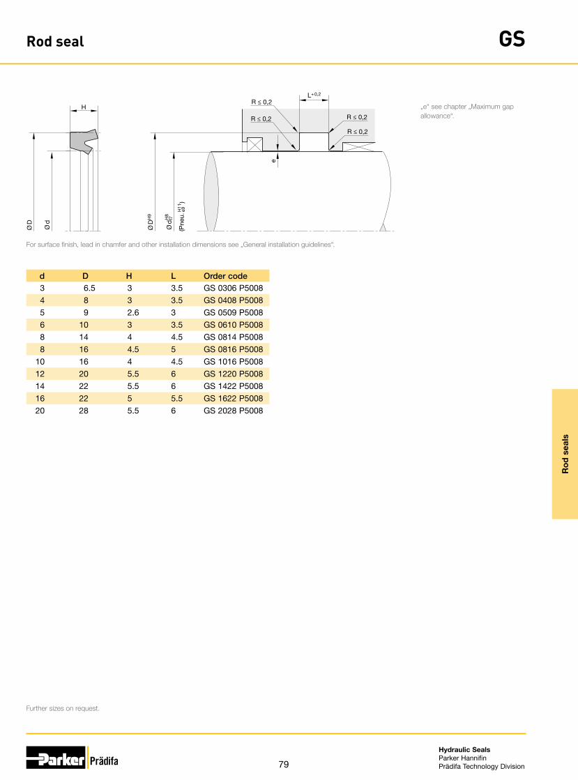
79
Hydraulic SealsParker HannifinPrädifa Technology Division
Ro
d s
eals
Rod seal GS
R ≤ 0,2
R ≤ 0,2
Ø D
H9
(Pne
u. e9
)
H8
H11
Ø d
f7
Ø D
Ø d
L+ 0,2
H
e
R ≤ 0,2
R ≤ 0,2
For surface finish, lead in chamfer and other installation dimensions see „General installation guidelines“.
„e“ see chapter „Maximum gap allowance“.
Further sizes on request.
d, D, H, L, Order code3 6.5 3 3.5 GS 0306 P50084 8 3 3.5 GS 0408 P50085 9 2.6 3 GS 0509 P50086 10 3 3.5 GS 0610 P50088 14 4 4.5 GS 0814 P50088 16 4.5 5 GS 0816 P5008
10 16 4 4.5 GS 1016 P500812 20 5.5 6 GS 1220 P500814 22 5.5 6 GS 1422 P500816 22 5 5.5 GS 1622 P500820 28 5.5 6 GS 2028 P5008

80
Hydraulic SealsParker HannifinPrädifa Technology Division
Ro
d s
eals
Rod seal HL
The HL Ultrathan® rod seal is a friction-optimised sealing solution for mobile and sta-tionary hydraulic applications, featuring a new type of functional principle: the single-acting rod seal has pressure-activated, cascading dynamic sealing edges.This design clearly reduces static and dynamic friction in hydraulic cylinders and in-creases the efficiency of hydraulic systems.
• Minimal break-away and dynamic fric-tion and no stick-slip tendency ensures uniform motion even at low speeds.
• No stick-slip tendency in case of low sliding speeds.
• Low break-away and dynamic friction, even after prolonged standstill under high pressure.
• Constantly low dynamic friction throughout the part‘s service life.
• Insensitive to pressure peaks.• Improved lubrication due to pressure
medium deposit in the dynamic contact area.
• High extrusion resistance.• Excellent media resistance in case of
suitable compound selection.• Suitable compounds available for
special requirements of the chemical process industry.
• Suitable compounds available for spe-cial requirements of the food processing industry.
• Dimensions according to ISO 5597.• Short axial assembly length.• Installation in closed and undercut
housings.• Additional sizes of machined products
available on short notice.
Range of applicationMainly for applications with increased requirements regarding friction and sliding be-haviour in mobile and stationary hydraulics. The dimensions mainly conform to the requirements of ISO 5597 for housing and diameters respectively.
Operating pressure ≤ 250 bar
Operating temperature -35 °C to +110 °C
Sliding speed ≤ 1 m/s
Media Hydraulic oils based on mineral oil and PAO fluids
CompoundsThe Ultrathan® P6030 compound is a Parker material based on polyurethane with a hardness of approx. 93 Shore A. Its main advantages in comparison with other poly-urethane materials currently available on the market are its excellent wear resistance, low compression set and improved temperature resistance.
InstallationThe seals should have an axial clearance (see columns H and L). To avoid damage at the sealing lips, the seals should not be pulled over sharp edges during installation.Normally these seals may be snapped into closed grooves. Where access is restricted special assembly tools may be required. Proposals for the design of such tools will be provided on request. For gap sizes see chapter „Maximum Gap Allowance“.
In case of special operating conditions (specific pressure loads, temperature, speed, use in water, HFA, HFB fluids etc.), please contact our consultancy service for a selection of the material and design best suit-ing your particular application requirements.

81
Hydraulic SealsParker HannifinPrädifa Technology Division
Ro
d s
eals
Rod seal HL Ø
D
Ø d
H
Ø D
H11
L+ 0,25
*)
e
H8
Ø d
f7
R ≤ 0,2
R ≤ 0,2
R ≤ 0,2
R ≤ 0,2
For surface finish, lead in chamfer and other installation dimensions see „General installation guidelines“.
Further sizes on request.
d, D, H, L, Order code20 28 4.5 5 HL 2028 P603022 30 4.5 5 HL 2230 P603025 33 4.5 5 HL 2533 P603030 40 5.7 6.3 HL 3040 P603032 42 5.7 6.3 HL 3242 P603035 45 5.7 6.3 HL 3545 P603036 46 5.7 6.3 HL 3646 P603037 47 5.7 6.3 HL 3747 P603040 50 5.7 6.3 HL 4050 P603045 55 5.7 6.3 HL 4555 P603050 60 5.7 6.3 HL 5060 P603056 66 6.5 7 HL 5666 P603063 72.6 5.5 6.3 HL 6372 P603065 75 7 7.5 HL 6575 P6030

82
Hydraulic SealsParker HannifinPrädifa Technology Division
Ro
d s
eals
Rod seal R3
The profile R3 rod seal is a sealing element of compact design with a special anti-extrusion ring.The main advantages of this combination are smooth running, excellent sealing per-formance and high wear resistance, even under exceptionally hard working condi-tions.These rod seals guarantee a leakfree performance even at low pressures or when rod movement occurs without pressure.
• Enhanced sealing performance in non-pressurized conditions.
• Good wear resistance.• Insensitive to pressure peaks.• High temperature resistance in case of
suitable compound selection.• Improved lubrication due to pressure
medium deposit in the dynamic contact area.
• High extrusion resistance.• Excellent media resistance in case of
suitable compound selection.• Suitable compounds available for
special requirements of the chemical process industry.
• Suitable compounds available for spe-cial requirements of the food processing industry.
• Dimensions according to ISO 5597.• Installation in closed and undercut
housings.
Range of applicationSeals for piston rods in hydraulic cylinders.
Operating pressure ≤ 315 bar
Operating temperature -30 °C to +100 °C
Sliding speed ≤ 0.5 m/s
CompoundsRubber part:Standard: N3544, NBR compound (≈ 88 Shore A).For high temperatures: V3664, FKM compound (≈ 85 Shore A).Glide ring: Polon® 062, modified PTFE + 60 % bronze.
InstallationThis rod seal profile R3 is manufactured with a slightly oversized outer diameter, thus ensuring a tight fit in the groove. The preload at the inner diameter necessary for the functioning of the seal will only be generated after installation.The working life of the seal is mainly influenced by the max. gap at the pressure-opposite of the sealing element.
In case of special operating conditions (specific pressure loads, temperature, speed, use in water, HFA, HFB fluids etc.), please contact our consultancy service for a selection of the material and design best suit-ing your particular application requirements.

83
Hydraulic SealsParker HannifinPrädifa Technology Division
Ro
d s
eals
Rod seal R3
R ≤ 0,2
*R ≤ 0,3
R ≤ 0,2
*R ≤ 0,3
Ø D
H9
H8
Ø d
f7
Ø d
1+ 0
,1
Ø D
Ø d
L+ 0,25
H
For surface finish, lead in chamfer and other installation dimensions see „General installation guidelines“.
* In the case of designs according to ISO standard, the radii given there should be used.
1) ISO 5597* Moulds not available on the date of printing.Further sizes on request.
d, D, H, L, d1, ISO1) Order code10 18 5.8 6.3 10.2 • R3 0010 0025212 20 5.8 6.3 12.2 • R3 0012 0025212 20 7 7.5 12.2 R3 0013 0025214 22 5.8 6.3 14.2 • R3 0015 0025214 22 7 7.5 14.2 R3 0009 0025214 24 7.5 8 14.2 • R3 0016 0025215 24 7 7.5 15.2 R3 0008 0025216 24 5.8 6.3 16.2 • R3 0017 0025216 26 7.5 8 16.2 • R3 0018 0025218 25 7 7.5 18.2 R3 0019 0025218 26 5.8 6.3 18.2 • R3 0020 0025220 28 5.8 6.3 20.3 • R3 0022 0025220 30 7.5 8 20.3 • R3 0023 0025220 30 8 9 20.3 R3 0024 0025222 30 5.8 6.3 22.3 • R3 0025 0025222 30 7 7.5 22.3 R3 0026 0025222 32 7.5 8 22.3 • R3 0028 0025225 33 5.8 6.3 25.3 • R3 0029 0025225 33 7 7.5 25.3 R3 0030 00252*25 35 7.5 8 25.3 • R3 0031 0025225 37 10 11 25.3 R3 0032 0025225 40 10 11 25.3 R3 0531 0025228 36 7 7.5 28.3 R3 0034 0025228 38 7.5 8 28.3 • R3 0035 0025228 38 8 9 28.3 R3 0036 0025228 40 9 10 28.3 R3 0027 0025230 38 7 7.5 30.3 R3 0033 0025230 40 10 11 30.3 R3 0004 0025232 42 7.5 8 32.3 • R3 0038 0025232 44 10 11 32.3 R3 0039 0025232 45 10 11 32.3 R3 0049 0025235 43 7 7.5 35.3 R3 0535 0025235 45 8.5 9.5 35.3 R3 0050 0025236 44 7 7.5 36.3 R3 0042 00252
d, D, H, L, d1, ISO1) Order code36 44 8 9 36.3 R3 0043 0025236 46 7.5 8 36.3 • R3 0044 0025236 46 10 11 36.3 R3 0045 0025236 51 11.5 12.5 36.3 • R3 0047 0025240 48 7.5 8 40.4 R3 0540 0025140 50 7.5 8 40.4 • R3 0040 0025140 50 10 11 40.4 R3 0050 0025140 55 10 11 40.4 R3 0006 0025242 54 10 11 42.4 R3 0037 0025145 53 5.8 6.3 45.4 • R3 0076 0025145 53 8 9 45.4 R3 0073 0025145 55 7.5 8 45.4 • R3 0053 0025145 55 10 11 45.4 R3 0054 0025145 60 11 12.5 45.4 • R3 0055 0025150 60 7.5 8 50.4 • R3 0056 0025150 65 10 11 50.4 • R3 0007 0025250 65 11.5 12.5 50.4 • R3 0058 0025152 68 12 13 52.4 R3 0052 0025255 63 7 7.5 55.4 R3 0064 0025156 68 10 11 56.4 R3 0077 0025156 71 12 12.5 56.4 • R3 0059 0025156 76 15 16 56.4 R3 0060 0025160 68 8 9 60.4 R3 0066 0025160 70 7.5 8 60.4 R3 0067 0025160 72 10 11 60.4 R3 0061 0025160 75 12 13 60.4 R3 0065 0025160 80 16 17 60.4 R3 0071 0025163 78 11.5 12.5 63.4 • R3 0062 0025170 82 10 11 70.4 R3 0068 0025170 85 12 12.5 70.4 • R3 0069 0025170 90 15 16 70.4 R3 0070 0025180 92 10 11 80.4 R3 0079 0025180 95 12 12.5 80.4 • R3 0080 0025190 105 12 12.5 90.4 • R3 0090 00251

84
Hydraulic SealsParker HannifinPrädifa Technology Division
Ro
d s
eals
Rod seal R3
R ≤ 0,2
*R ≤ 0,3
R ≤ 0,2
*R ≤ 0,3
Ø D
H9
H8
Ø d
f7
Ø d
1+ 0
,1
Ø D
Ø d
L+ 0,25
H
For surface finish, lead in chamfer and other installation dimensions see „General installation guidelines“.
* In the case of designs according to ISO standard, the radii given there should be used.
1) ISO 5597* Moulds not available on the date of printing.Further sizes on request.
d, D, H, L, d1, ISO1) Order code90 110 15 16 90.4 • R3 0091 00251
100 115 12 13 100.4 R3 0100 00251100 120 15 16 100.4 • R3 0101 00251100 125 19 20 100.4 R3 0102 00251110 130 15 16 110.4 • R3 0110 00251125 145 15 16 125.4 • R3 0125 00251130 150 15 16 130.4 R3 0130 00251140 160 15 16 140.4 • R3 0140 00251160 185 19 20 160.4 • R3 0160 00251180 205 19 20 180.4 • R3 0180 00251200 225 19 20 200.4 • R3 0200 00251280 310 23 25 280.4 • R3 0280 00251320 360 30 32 320.4 • R3 0320 00252360 400 30 32 360.4 • R3 0360 00252

85
Hydraulic SealsParker HannifinPrädifa Technology Division
Ro
d s
eals
Rod seal B3
The profile B3 Ultrathan® rod seal is a lipseal which fits in the groove. These seals may be used for all applications where the physical properties of normal or fabric reinforced elastomers are insufficient.
• Robust seal profile for harshest operat-ing conditions.
• Extreme wear resistance.• Easier installation.• Insensitive to pressure peaks.• High extrusion resistance.• Excellent media resistance in case of
suitable compound selection.• Suitable compounds available for
special requirements of the chemical process industry.
• Suitable compounds available for spe-cial requirements of the food processing industry.
• Dimensions according to ISO 5597.• Installation in closed and undercut
housings.• Low compression set.• Additional sizes of machined products
available on short notice.
Range of applicationMainly for the sealing of piston rods and plungers in heavy duty applications in mo-bile and stationary hydraulics. The dimensions mainly conform to the requirements of ISO 5597 and ISO 3320 for housing and diameters respectively.
Operating pressure ≤ 400 bar
Operating temperature -35 °C to +110 °C
Sliding speed ≤ 0.5 m/s
Media Hydraulic oils based on mineral oil
CompoundsThe Ultrathan® P5008 compound is a Parker material based on polyurethane with a hardness of approx. 93 Shore A. Its main advantages in comparison with other poly-urethane materials currently available on the market are the increased heat resistance and the lower compression set.For media containing water, we recommend our hydrolysis resistent polyurethane compound P5001.
InstallationThe seals should have an axial clearance (see columns H and L). To avoid damage at the sealing lips, the seals should not be pulled over sharp edges during installation.Normally these seals may be snapped into closed grooves. Where access is restricted special assembly tools may be required. Proposals for the design of such tools will be provided on request. For gap sizes see chapter “Maximum Gap Allowance”.
In case of special operating conditions (specific pressure loads, temperature, speed, use in water, HFA, HFB fluids etc.), please contact our consultancy service for a selection of the material and design best suit-ing your particular application requirements.

86
Hydraulic SealsParker HannifinPrädifa Technology Division
Ro
d s
eals
Rod seal B3 Ø
D
Ø d
H
Ø D
H11
H8
Ø d
f7
L+ 0,25
*)
R ≤ 0,2
R ≤ 0,2
e
R ≤ 0,2
R ≤ 0,2
For surface finish, lead in chamfer and other installation dimensions see „General installation guidelines“.
* In the case of designs according to ISO standard, the radii given there should be used.„e“ see chapter „Maximum gap allowance“.
1) For housings according to ISO 5597 for ISO 6020-2 cylinders.2) Standard sizes for housings according to ISO 5597.Further sizes on request.
d, D, H, L, ISO1) ISO2) Order code4 12 6 7 B3 0412 P50086 13 5 5.6 B3 0613 P50086 14 5.7 6.3 • B3 0614 P50088 14 5 5.6 B3 0814 P50088 16 5.7 6.3 • B3 0816 P50089 14.5 5 5.6 B3 0914 P50089 16 5.7 6.3 B3 0916 P5008
10 14 3.7 4.2 B3 1015 P500810 16 4.5 5.2 B3 1016 P500810 17 5.7 6.3 B3 1017 P500810 18 5.7 6.3 • B3 1018 P500812 19 5 5.6 • • B3 1211 P500812 20 5.7 6.3 • B3 1212 P500812 22 7.3 8 • B3 1222 P500814 21 5 5.6 • • B3 1421 P500814 22 7.3 8 B3 1422 P500814 24 7.3 8 • B3 1424 P500814 24 8 9 B3 1425 P500814.28 20.7 3.5 3.9 B3 1428 P500815 25 6 6.7 B3 1515 P500815 25 8 9 B3 1525 P500816 22 5 5.6 B3 1620 P500816 24 5.7 6.3 • B3 1624 P500816 26 7.3 8 • B3 1626 P500818 24 5 5.6 B3 1824 P500818 25 5 5.6 • • B3 1826 P500818 26 5.7 6.3 B3 1825 P500818 28 7.3 8 • B3 1827 P500818 28 8 9 B3 1828 P500819.05 25.4 6.35 7.14 B3 1905 P500820 26 5 5.6 B3 2026 P500820 28 5.7 6.3 • B3 2028 P500820 30 7.3 8 • B3 2030 P500822 28 5 5.6 B3 2225 P5008
d, D, H, L, ISO1) ISO2) Order code22 29 5 5.6 • • B3 2229 P500822 30 5.7 6.3 • B3 2230 P500822 32 7.3 8 • B3 2232 P500825 32 6 7 B3 2525 P500825 33 5.7 6.3 • B3 2532 P500825 33 6.5 7.3 B3 2533 P500825 33 8 9 B3 2534 P500825 35 7.3 8 • B3 2535 P500825 40 10 11 B3 2537 P500825 40 11 12 B3 2539 P500828 36 5.7 6.3 • • B3 2836 P500828 36 8 9 B3 2837 P500828 38 7.3 8 • B3 2038 P500828 38 10 11 B3 2838 P500828 43 11.4 12.5 B3 2843 P500830 38 5.7 6.3 B3 3003 P500830 38 8 9 B3 3002 P500830 40 7.3 8 • B3 3040 P500830 40 10 11 B3 3005 P500830 45 10 11 B3 3015 P500832 40 6 7 B3 3206 P500832 40 6.7 7.5 B3 3240 P500832 42 7.3 8 • B3 3242 P500832 42 10 11 B3 3243 P500832 45 10 11 B3 3245 P500832 47 10 11 B3 3020 P500834.9 47.6 9.9 11 B3 3490 P500835 43 6 6.7 B3 3506 P500835 45 7 8 B3 3544 P500835 45 10 11 B3 3545 P500836 44 5.7 6.3 • • B3 3644 P500836 46 7.3 8 • B3 3646 P500838 50 10 11 B3 3800 P500838.1 50.8 9.53 10.3 B3 3801 P5008

87
Hydraulic SealsParker HannifinPrädifa Technology Division
Ro
d s
eals
Rod seal B3 Ø
D
Ø d
H
Ø D
H11
H8
Ø d
f7
L+ 0,25
*)
R ≤ 0,2
R ≤ 0,2
e
R ≤ 0,2
R ≤ 0,2
For surface finish, lead in chamfer and other installation dimensions see „General installation guidelines“.
* In the case of designs according to ISO standard, the radii given there should be used.„e“ see chapter „Maximum gap allowance“.
1) For housings according to ISO 5597 for ISO 6020-2 cylinders.2) Standard sizes for housings according to ISO 5597.Further sizes on request.
d, D, H, L, ISO1) ISO2) Order code40 48 5.7 6.3 B3 4002 P500840 48 8 9 B3 4003 P500840 50 7.3 8 • B3 4004 P500840 50 8 9 B3 4006 P500840 50 10 11 B3 4005 P500841.22 50.8 8.3 9.1 B3 4022 P500842 52 7.3 8 B3 5242 P500842.25 52 9.5 10.5 B3 4043 P500845 53 5.6 6.3 • • B3 4050 P500845 53 8 9 B3 4502 P500845 53 10 11 B3 4553 P500845 55 5.8 6.5 B3 4554 P500845 55 7.3 8 • B3 4555 P500845 55 10 11 B3 4556 P500845 57 9 10 B3 4557 P500845 60 11.4 12.5 • B3 4560 P500850 58 8 9 B3 5002 P500850 60 7.3 8 • B3 5004 P500850 60 10 11 B3 5006 P500850 63 10 11 B3 050L P500850 65 11.4 12.5 • B3 5065 P500850 70 14 15.5 B3 5067 P500850.8 63.5 9.5 10.3 B3 5008 P500855 63 8 9 B3 5555 P500855 65 7.3 8 B3 5563 P500855 65 10 11 B3 5565 P500855 65 12 13 B3 5570 P500855 70 10 11 B3 5070 P500856 66 6.5 7.5 • • B3 5666 P500856 71 8.6 9.5 B3 5668 P500856 71 11.4 12.5 • B3 5671 P500857.15 69.85 9.53 10.3 B3 5077 P500858 68 7.3 8 B3 5868 P500860 68 8 9 B3 6068 P5008
d, D, H, L, ISO1) ISO2) Order code60 70 10 11 B3 6070 P500860 75 10 11 B3 6074 P500860.33 73.03 9.53 10.3 B3 6033 P500863 73 6.5 7.3 B3 6372 P500863 73 12 13 B3 6373 P500863 75 10 11 B3 6375 P500863 78 10 11 B3 6377 P500863 78 11.4 12.5 • B3 6378 P500863.5 76.2 9.53 10.3 B3 6064 P500865 73 8 9 B3 6502 P500865 75 7 8 B3 6076 P500865 75 12 13 B3 6075 P500865 78 10 11 B3 065C P500865 80 12 13 B3 6504 P500869.8 82.6 9.75 10.5 B3 6980 P500870 78 8 9 B3 7070 P500870 80 6.5 7.5 B3 7079 P500870 80 7 7.8 B3 7078 P500870 80 12 13 B3 7080 P500870 82 8.7 9.7 B3 7082 P500870 85 11.4 12.5 • B3 7085 P500875 85 7 8 B3 7585 P500875 85 12 13 B3 7586 P500875 88 10 11 B3 7588 P500875 90 10 11 B3 7590 P500875 90 12 13 B3 7591 P500876 88 6 7 B3 076A P500876.2 88.9 9.53 10.3 B3 7620 P500878 86 8.5 9.5 B3 7800 P500880 90 7 8 B3 8088 P500880 90 10 11 B3 8089 P500880 90 12 13 B3 8090 P500880 95 10 11 B3 8093 P500880 95 11.4 12.5 • B3 8094 P5008

88
Hydraulic SealsParker HannifinPrädifa Technology Division
Ro
d s
eals
Rod seal B3 Ø
D
Ø d
H
Ø D
H11
H8
Ø d
f7
L+ 0,25
*)
R ≤ 0,2
R ≤ 0,2
e
R ≤ 0,2
R ≤ 0,2
For surface finish, lead in chamfer and other installation dimensions see „General installation guidelines“.
* In the case of designs according to ISO standard, the radii given there should be used.„e“ see chapter „Maximum gap allowance“.
1) For housings according to ISO 5597 for ISO 6020-2 cylinders.2) Standard sizes for housings according to ISO 5597.Further sizes on request.
d, D, H, L, ISO1) ISO2) Order code80 100 12 13 B3 8099 P500880 105 12 13 B3 085C P500885 100 9 10 B3 8509 P500885 100 12 13 B3 8510 P500885 105 12 13 B3 8505 P500888.9 101.6 9.53 10.3 B3 8889 P500890 100 6.5 7.5 • • B3 9001 P500890 102 9 10 B3 9002 P500890 105 9 10 B3 9004 P500890 105 11.4 12.5 B3 9006 P500890 105 11.4 12.5 • B3 9005 P500890 110 12 13 B3 9009 P500890 110 14.5 16 B3 9010 P500892 105 9.5 10.6 B3 9210 P500895 110 9 10 B3 9505 P500895 110 10 11 B3 095B P500895 115 12 13 B3 095C P5008
100 115 9 10 B3 A015 P5008100 120 11.5 12.5 B3 A018 P5008100 120 14.5 16 • B3 A020 P5008101.6 117.48 9.53 10.3 B3 A060 P5008105 120 10 11 B3 A503 P5008105 120 11.4 12.5 B3 A511 P5008105 125 14.5 16 B3 A505 P5008110 125 9 10 B3 B024 P5008110 125 9.6 10.6 • • B3 B025 P5008110 130 12 13 B3 B029 P5008110 130 14.5 16 • B3 B030 P5008114.3 130.18 9.53 10.3 B3 B044 P5008115 135 11.5 12.5 B3 B052 P5008120 135 14.5 16 B3 C017 P5008120 140 15 16 B3 C040 P5008125 145 12 13 B3 C244 P5008125 145 14.5 16 • B3 C245 P5008
d, D, H, L, ISO1) ISO2) Order code125.1 140.5 9.8 10.9 B3 C224 P5008130 150 12 13 B3 D049 P5008130 150 15 16 B3 D050 P5008139.7 155.58 9.53 10.3 B3 D097 P5008140 150 6 7 B3 140E P5008140 155 9.6 10.6 • • B3 E055 P5008140 160 14.5 16 • B3 E060 P5008145 165 14.5 16 B3 E065 P5008150 170 15 16 B3 F070 P5008152.4 171.45 12.7 13.49 B3 F072 P5008160 180 15 16 B3 G080 P5008160 185 18.2 20 • B3 G085 P5008170 200 18.2 20 B3 H020 P5008180 200 15 16 B3 J020 P5008180 205 18.2 20 • B3 J005 P5008190 210 15 16 B3 K005 P5008200 220 12 13 B3 200A P5008200 225 18.2 20 • B3 L025 P5008200 230 18 19 B3 L030 P5008210 230 15 16 B3 L110 P5008220 250 22.7 25 • B3 M050 P5008225 250 18 19 B3 M070 P5008250 280 22.7 25 • B3 N580 P5008280 300 15 16 B3 P005 P5008280 310 22.7 25 • B3 P010 P5008390 420 22.7 25 B3 Q420 P5008

89
Hydraulic SealsParker HannifinPrädifa Technology Division
Ro
d s
eals
Rod seal BS
The profile BS Ultrathan® rod seal is a lip seal with a secondary sealing lip and tight fit at the outer diameter. Wear and dry run are largely prevented by the additional lu-bricant retained under the seal, created by the secondary lip. In some cases this sec-ond sealing lip may even act as a substitute for a costly tandem-arrangement when complete sealing under certain working conditions can only be achieved by two seals placed one behind the other in separate housings.
For telescopic cylinders, we recommend the version with a 4-mm profile width.
• Excellent sealing performance due to elongated contact area and multiple sealing lips.
• Exceptionally high static and dynamic sealing performance.
• Enhanced sealing performance in non-pressurized conditions.
• Penetration of air into the system is largely prevented.
• Robust seal profile for harshest operat-ing conditions.
• Extreme wear resistance.• Easier installation.• Insensitive to pressure peaks.• Improved lubrication due to pressure
medium deposit in the dynamic contact area.
• High extrusion resistance.• Excellent media resistance in case of
suitable compound selection.• Suitable compounds available for
special requirements of the chemical process industry.
• Suitable compounds available for spe-cial requirements of the food processing industry.
• Dimensions according to ISO 5597.• Short radial assembly depth.• Installation in closed and undercut
housings.• Additional sizes of machined products
available on short notice.
Range of applicationMainly for the sealing of piston rods and plungers in heavy duty applications in mo-bile and stationary hydraulics. The dimensions mainly conform to the requirements of ISO 5597 and ISO 3320 for housing and diameters respectively.
Operating pressure ≤ 400 bar
Operating temperature -35 °C to +110 °C
Sliding speed ≤ 0.5 m/s
Media Hydraulic oils based on mineral oil
CompoundsThe compound Ultrathan® P5008 is a Parker material based on polyurethane with a hardness of approx. 93 Shore A. Its main advantages in comparison with other poly-urethane materials currently available on the market are the increased heat resistance and the lower compression set.For media containing water, we recommend our hydrolysis-resistent polyurethane compound P5001.
InstallationThe seals should have an axial clearance (see columns H and L). To avoid damage at the sealing lips, the seals should not be pulled over sharp edges during installation.Normally these seals may be snapped into closed grooves. Where access is restricted special assembly tools may be required. Proposals for the design of such tools will be provided on request. For gap sizes see chapter “Maximum Gap Allowance”.
In case of special operating conditions (specific pressure loads, temperature, speed, use in water, HFA, HFB fluids etc.), please contact our consultancy service for a selection of the material and design best suit-ing your particular application requirements.

90
Hydraulic SealsParker HannifinPrädifa Technology Division
Ro
d s
eals
Rod seal BS
Ø D
H11
H8
Ø d
f7
Ø D
Ø d
L+ 0,25
H
*)
R ≤ 0,2
R ≤ 0,2
e
R ≤ 0,2
R ≤ 0,2
For surface finish, lead in chamfer and other installation dimensions see „General installation guidelines“.
* In the case of designs according to ISO standard, the radii given there should be used.„e“ see chapter „Maximum gap allowance“.
1) For housings according to ISO 5597 for ISO 6020-2 cylinders.2) Standard sizes for housings according to ISO 5597.Further sizes on request.
d, D, H, L, ISO1) ISO2) Order code8 16 5.7 6.3 • BS 0816 P50089 16 5.7 6.3 BS 0916 P5008
10 16 4.5 5.3 BS 1016 P500810 17 5.7 6.3 BS 1017 P500810 18 5.7 6.3 • BS 1018 P500812.7 19.05 4.5 5.3 BS 1270 P500814 20 5.7 6.3 BS 1420 P500814 22 5.7 6.3 • BS 1422 P500814 24 7.3 8 • BS 1424 P500816 24 5.8 6.3 • BS 1624 P500816 26 7.3 8 • BS 1626 P500818 28 7.3 8 • BS 1827 P500820 30 7.3 8 • BS 2030 P500822 32 7.3 8 • BS 2232 P500825 33 6.5 7.3 BS 2533 P500825 35 7.3 8 • BS 2535 P500826 36 10 11 BS 2605 P500828 36 7 7.5 BS 2836 P500828 38 7.3 8 • BS 2838 P500830 40 10 11 BS 3005 P500830 45 10 11 BS 3030 P500832 42 7.3 8 • BS 3242 P500832 42 10 11 BS 3243 P500832 45 10 11 BS 3245 P500835 45 10 11 BS 3545 P500835 50 10 11 BS 3550 P500836 46 7.3 8 • BS 3646 P500836 48 10 11 BS 3649 P500836 51 10 11 BS 3651 P500837 47 10 11 BS 3747 P500840 48 11.5 12.5 BS 4004 P500840 49.52 9.6 10.5 BS 4049 P500840 50 10 11 BS 4005 P500840 52 7.4 8 BS 5608 P5008
d, D, H, L, ISO1) ISO2) Order code40 52 8 9 BS 4008 P500840 55 11.4 12.5 • BS 4007 P500843 53 7.3 8 BS 4051 P500845 53 5.6 6.3 • • BS 4553 P500845 55 7.3 8 • BS 4555 P500845 55 10 11 BS 4556 P500845 57.7 9.6 10.5 BS 4557 P500845 60 10.5 11.5 BS 4562 P500845 60 11.4 12.5 • BS 4561 P500846 56 10 11 BS 4605 P500848 56 11.5 12.5 BS 4856 P500850 60 7.3 8 • BS 5004 P500850 60 10 11 BS 5006 P500850 62.7 9.6 10.5 BS 5062 P500850 65 10 11 BS 5064 P500850 65 11.4 12.5 • BS 5065 P500850.8 63.5 9.5 10.3 BS 5085 P500852 62 10 11 BS 5203 P500855 65 10 11 BS 5564 P500855 65 11 12 BS 5565 P500855 67 10 11 BS 5567 P500856 71 11.4 12.5 • BS 5609 P500858 66 11.5 12.5 BS 5866 P500860 68 13 14 BS 6068 P500860 70 7.5 8.5 BS 6069 P500860 70 10 11 BS 6070 P500860 75 10 11 BS 6074 P500863 71 8 9 BS 6371 P500863 78 10 11 BS 6377 P500863 78 11.4 12.5 • BS 6378 P500865 73 11.5 12.5 BS 6573 P500865 75 12 13 BS 6075 P500865 85 11.4 12.5 BS 6578 P500868 78 12 13 BS 6805 P5008

91
Hydraulic SealsParker HannifinPrädifa Technology Division
Ro
d s
eals
Rod seal BS
Ø D
H11
H8
Ø d
f7
Ø D
Ø d
L+ 0,25
H
*)
R ≤ 0,2
R ≤ 0,2
e
R ≤ 0,2
R ≤ 0,2
For surface finish, lead in chamfer and other installation dimensions see „General installation guidelines“.
* In the case of designs according to ISO standard, the radii given there should be used.„e“ see chapter „Maximum gap allowance“.
1) For housings according to ISO 5597 for ISO 6020-2 cylinders.2) Standard sizes for housings according to ISO 5597.Further sizes on request.
d, D, H, L, ISO1) ISO2) Order code70 80 12 13 BS 7080 P500870 85 10 11 BS 7084 P500870 85 11.4 12.5 • BS 7085 P500874 82 11.5 12.5 BS 7482 P500875 85 11.5 12.5 BS 7585 P500875 88 10 11 BS 7588 P500875 90 10 11 BS 7590 P500877 87 11.5 12.5 BS 7787 P500878 86 11.5 12.5 BS 7804 P500880 88 11.5 12.5 BS 8088 P500880 90 12 13 BS 8090 P500880 95 11.4 12.5 • BS 8095 P500880 100 12 13 BS 8099 P500881 89 11.5 12.5 BS 8150 P500882.55 95.25 9.53 10.3 BS 8255 P500885 93 11.5 12.5 BS 8593 P500885 100 12 13 BS 8510 P500890 98 11.5 12.5 BS 9098 P500890 105 11.4 12.5 • BS 9005 P500892 107 11.4 12.5 BS 9203 P500895 115 12 13 BS 9515 P500897 105 13 14 BS 9705 P5008
100 108 12 13 BS A008 P5008100 120 12 13 BS A019 P5008100 120 14.5 16 • BS A020 P5008105 113 11.5 12.5 BS A513 P5008105 117 9.1 10 BS A517 P5008107 115 11.5 12.5 BS A715 P5008110 125 14.5 16 BS B025 P5008110 130 14.5 16 • BS B030 P5008118 126 13 14 BS B805 P5008120 128 11.5 12.5 BS C028 P5008120 130 14 15 BS C030 P5008125 133 11.5 12.5 BS C233 P5008
d, D, H, L, ISO1) ISO2) Order code128 136 9.1 10 BS C836 P5008128 140 9.1 10 BS C840 P5008130 145 12 13 BS D045 P5008140 160 14.5 16 • BS E060 P5008143 151 13 14 BS E305 P5008145 153 11.5 12.5 BS E050 P5008150 170 15 16 BS F070 P5008152 160 9.1 10 BS F252 P5008152 164 9.1 10 BS F264 P5008160 185 18.2 20 • BS G085 P5008167 175 11.5 12.5 BS G704 P5008167 176 11.5 12.5 BS G705 P5008170 200 18 19 BS H020 P5008171 179 13 14 BS H105 P5008176 186 12 13 BS H160 P5008177.7 195 9.73 11.3 BS H169 P5008180 188 9.1 10 BS J080 P5008180 188 11.5 12.5 BS J088 P5008180 192 9.1 10 BS J092 P5008193 201 11.5 12.5 BS K003 P5008200 211 12 13 BS L005 P5008200 225 18.2 20 • BS L025 P5008209.55 226.77 9.73 11.3 BS L008 P5008212 220 9.1 10 BS L012 P5008212 224 9.1 10 BS L024 P5008220 228 11.5 12.5 BS M028 P5008220 250 22.7 25 • BS M050 P5008223 231 11.5 12.5 BS M060 P5008228.5 246 9 10 BS M085 P5008230 260 22.7 25 BS M110 P5008250 280 22.7 25 • BS N580 P5008266.7 284 9.73 11.3 BS O005 P5008280 310 18 19 BS P008 P5008

92
Hydraulic SealsParker HannifinPrädifa Technology Division
Ro
d s
eals
Slipper Seal® Rod sealing set OD
The single-acting rod sealing set profile OD consists of a PTFE rod sealing ring and an elastomer O-ring as a preloading element. The asymmetrical cross-section of the slipper ring is designed for best drag oil performance during stroke in both directions. Optimal sealing performance will be obtained if the rod sealing set is used in tandem with a double-wiper.
Profile OD is particularly suitable for sealing rods in control cylinders, servo-assisted equipment, machine tools and quick acting cylinders. The sealing set is also suitable for applications in the automotive (e.g. shock absorbers) and process industries.
The material combination of the slipper ring (PTFE) and the O-ring (elastomer) makes this product suitable for a wide range of applications, especially for aggressive media and/or high temperatures. Multiple compounds can alternatively be selected accord-ing to the individual application profile.
• Good sealing performance in extremely small assembly conditions.
• Excellent wear resistance.• Minimal break-away and dynamic fric-
tion and no stick-slip tendency ensures uniform motion even at low speeds.
• Good energy efficiency due to low fric-tion.
• Insensitive to pressure peaks.• High temperature resistance assured by
suitable O-ring compound selection.• High extrusion resistance.• Adaptable to nearly all media thanks to
high chemical resistance of the sealing ring and large O-ring compound selec-tion.
• Dimensions according to ISO 7425-2.• Also available as double-acting version.• Short axial assembly length.• Installation in closed and undercut
housings.• Available in diameters from 4 to
3000 mm.• Additional sizes of machined products
available on short notice.
Range of applicationOperating pressure ≤ 400 bar
in case of reduced extrusion gap (H7/f7) and large cross sections
≤ 600 bar
Operating temperature -30 °C to +100 °C 1)
Sliding speed ≤ 4 m/s
1) With deviation from standard temperature range, please contact our consultancy service for adequate O-ring compound.
CompoundsSealing ring: Polon® 052, modified PTFE + 40 % bronze.O-ring: N0674, NBR elastomer with approx. 70 Shore A.
InstallationFor diameters < 30 mm open grooves are required.
In case of special operating conditions (specific pressure loads, temperature, speed, use in water, HFA, HFB fluids etc.), please contact our consultancy service for a selection of the material and design best suit-ing your particular application requirements.

93
Hydraulic SealsParker HannifinPrädifa Technology Division
Ro
d s
eals
Slipper Seal® Rod sealing set OD
Ø D
H9
= d
+ 2
G
L+ 0,2
R ≤ 0,3
R ≤ 0,3
½ e
R1 R1
Ø d
f7(G
)
15°
Ø D
Ø d
For surface finish, lead in chamfer and other installation dimensions see „General installation guidelines“.
1) Housing dimensions according to ISO 7425-2
Housing dimensionsSeries
no.Cross-section
O-ring cross-section
Recommended rod Ø range
Groove width
Groove depth
Gap max. 0–200 bar
Gap max. 200–400 bar
Radius max.
ISO1)
(mm) d(mm)
L(mm)
G(mm)
e(mm)
e(mm)
R1(mm)
≥ <
00170 A 1.78 4 8 2.2 2.45 0.6 - 0.4 0.4 - 0.2 0.5
00170 B 2.62 8 19 3.2 3.65 0.8 - 0.5 0.5 - 0.3 0.5
00170 C 3.53 19 38 4.2 5.35 0.8 - 0.5 0.5 - 0.3 0.5
00170 D 5.33 38 200 6.3 7.55 1 - 0.6 0.6 - 0.4 0.9
00170 E 6.99 200 256 8.1 10.25 1 - 0.6 0.6 - 0.4 0.9
00170 F 6.99 256 650 8.1 12 1.2 - 0.7 0.7 - 0.5 0.9
00170 G 8.4 650 1000 9.5 13.65 1.4 - 0.8 0.8 - 0.6 0.9
00170 H 12 1000 - 13.8 19 1.4 - 0.8 0.8 - 0.6 0.9
00170 K 1.78 4 8 2.2 2.5 0.6 - 0.4 0.4 - 0.2 0.5 ●00170 L 2.62 8 19 3.2 3.75 0.8 - 0.5 0.5 - 0.3 0.5 ●00170 M 3.53 19 38 4.2 5.5 0.8 - 0.5 0.5 - 0.3 0.5 ●00170 N 5.33 38 200 6.3 7.75 1 - 0.6 0.6 - 0.4 0.9 ●00170 O 6.99 200 256 8.1 10.5 1 - 0.6 0.6 - 0.4 0.9 ●00170 P 6.99 256 650 8.1 12.25 1.2 - 0.7 0.7 - 0.5 0.9 ●

94
Hydraulic SealsParker HannifinPrädifa Technology Division
Ro
d s
eals
Slipper Seal® Rod sealing set OD
Ø D
H9
= d
+ 2
G
L+ 0,2
R ≤ 0,3
R ≤ 0,3
½ e
R1 R1
Ø d
f7(G
)
15°
Ø D
Ø d
For surface finish, lead in chamfer and other installation dimensions see „General installation guidelines“.
Ordering exampleRod diameter 40 mm
OD 0400 052 00171 D (40,0 × 55,1 × 6,3)
OD Profile
0400 Rod diameter × 10
052 Compound
00171 Series no. / compound code O-ring
00170 without O-ring
00171 N0674 (NBR) 70±5 Shore A -30 / +110 °C
00172 V0747 (FKM) 75±5 Shore A -25 / +200 °C
00173 N0756 (NBR) 75±5 Shore A -50 / +110 °C
00174 E0540 (EPDM) 80±5 Shore A -40 / +150°C
00175 N3578 (NBR) 75±5 Shore A -30 / +110 °C
00176 N0552 (NBR) 90±5 Shore A -30 / +100 °C
00177 N1173 (HNBR) 70±5 Shore A -30 / +150 °C
D Cross-section
Please note: For certain applications, it might be convenient to use a non-standard cross-section – reduced or heavier. In these cases, please replace the standard cross-section code (in above example: „D“) by the one you require (for example „C“ or „E“).

95
Hydraulic SealsParker HannifinPrädifa Technology Division
Ro
d s
eals
Slipper Seal® Rod sealing set OD
Ø D
H9
= d
+ 2
G
L+ 0,2
R ≤ 0,3
R ≤ 0,3
½ e
R1 R1
Ø d
f7(G
)
15°
Ø D
Ø d
For surface finish, lead in chamfer and other installation dimensions see „General installation guidelines“.
1) ISO 7425-2Further sizes on request.
Standard rangeSize Groove O-ring ISO1)
Ø d Ø D L No. CS ID
(mm) (mm) (mm) (mm) (mm)
0040 4 8.90 2.20 2-010 1.78 6.07
0050 5 9.90 2.20 2-010 1.78 6.07
0060 6 11 2.20 2-011 1.78 7.65 ●0070 7 11.90 2.20 2-012 1.78 9.25
0080 8 13 2.20 2-012 1.78 9.25 ●0080 8 15.30 3.20 2-111 2.62 10.77
0100 10 15 2.20 2-013 1.78 10.82 ●0100 10 17.30 3.20 2-112 2.62 12.37
0120 12 17 2.20 2-015 1.78 14 ●0120 12 19.30 3.20 2-114 2.62 15.54
0120 12 19.50 3.20 2-114 2.62 15.54 ●0140 14 19 2.20 2-016 1.78 15.60 ●0140 14 21.50 3.20 2-115 2.62 17.12 ●0150 15 22.30 3.20 2-116 2.62 18.72
0160 16 23.50 3.20 2-116 2.62 18.72 ●0180 18 25.30 3.20 2-117 2.62 20.29
0180 18 25.50 3.20 2-117 2.62 20.29 ●0200 20 27.50 3.20 2-118 2.62 21.89 ●0200 20 30.70 4.20 2-214 3.53 24.99
0200 20 31 4.20 2-214 3.53 24.99 ●0220 22 29.50 3.20 2-120 2.62 25.07 ●0220 22 32.70 4.20 2-215 3.53 26.57
0220 22 33 4.20 2-215 3.53 26.57 ●0250 25 32.50 3.20 2-122 2.62 26.24 ●0250 25 35.70 4.20 2-217 3.53 29.32
0250 25 36 4.20 2-217 3.53 29.32 ●0260 26 36.70 4.20 2-218 3.53 31.34
0280 28 38.70 4.20 2-219 3.53 32.92
0280 28 39 4.20 2-219 3.53 32.92 ●0300 30 40.70 4.20 2-220 3.53 34.52
Size Groove O-ring ISO1)
Ø d Ø D L No. CS ID
(mm) (mm) (mm) (mm) (mm)
0320 32 42.70 4.20 2-221 3.53 36.09
0320 32 43 4.20 2-221 3.53 36.09 ●0350 35 45.70 4.20 2-222 3.53 37.69
0360 36 47 4.20 2-223 3.53 40.87 ●0380 38 53.10 6.30 2-327 5.33 43.82
0400 40 51 4.20 2-224 3.53 44.04 ●0400 40 55.10 6.30 2-328 5.33 46.99
0420 42 57.10 6.30 2-328 5.33 46.99
0450 45 56 4.20 2-226 3.53 50.39 ●0450 45 60.10 6.30 2-329 5.33 50.17
0480 48 63.10 6.30 2-330 5.33 53.34
0500 50 61 4.20 2-227 3.53 53.57 ●0500 50 65.10 6.30 2-331 5.33 56.52
0520 52 67.10 6.30 2-331 5.33 56.52
0550 55 70.10 6.30 2-332 5.33 59.69
0560 56 67 4.20 2-229 3.53 59.92 ●0560 56 71.50 6.30 2-332 5.33 59.69 ●0580 58 73.10 6.30 2-333 5.33 62.87
0600 60 75.10 6.30 2-334 5.33 66.04
0630 63 74 4.20 2-231 3.53 66.27 ●0630 63 78.50 6.30 2-335 5.33 69.22 ●0650 65 80.10 6.30 2-335 5.33 69.22
0700 70 85.10 6.30 2-337 5.33 75.57
0700 70 85.50 6.30 2-337 5.33 75.57 ●0750 75 90.10 6.30 2-339 5.33 81.92
0800 80 95.10 6.30 2-340 5.33 85.09
0800 80 95.50 6.30 2-340 5.33 85.09 ●0850 85 100.10 6.30 2-342 5.33 91.44
0900 90 105.10 6.30 2-343 5.33 94.62
0900 90 105.50 6.30 2-343 5.33 94.62 ●

96
Hydraulic SealsParker HannifinPrädifa Technology Division
Ro
d s
eals
Slipper Seal® Rod sealing set OD
Ø D
H9
= d
+ 2
G
L+ 0,2
R ≤ 0,3
R ≤ 0,3
½ e
R1 R1
Ø d
f7(G
)
15°
Ø D
Ø d
For surface finish, lead in chamfer and other installation dimensions see „General installation guidelines“.
1) ISO 7425-2Further sizes on request.
Size Groove O-ring ISO1)
Ø d Ø D L No. CS ID
(mm) (mm) (mm) (mm) (mm)
0950 95 110.10 6.30 2-345 5.33 100.97
1000 100 115.10 6.30 2-346 5.33 104.14
1000 100 115.50 6.30 2-346 5.33 104.14 ●1100 110 125.10 6.30 2-350 5.33 116.84
1100 110 125.50 6.30 2-350 5.33 116.84 ●1200 120 135.10 6.30 2-353 5.33 126.37
1250 125 140.10 6.30 2-354 5.33 129.54
1250 125 140.50 6.30 2-354 5.33 129.54 ●1300 130 145.10 6.30 2-356 5.33 135.89
1400 140 155.10 6.30 2-359 5.33 145.42
1400 140 155.50 6.30 2-359 5.33 145.42 ●1500 150 165.10 6.30 2-361 5.33 151.77
1600 160 175.10 6.30 2-363 5.33 164.47
1600 160 175.50 6.30 2-363 5.33 164.47 ●1600 160 181 8.10 2-439 6.99 164.47 ●1700 170 185.10 6.30 2-365 5.33 177.17
1750 175 190.10 6.30 2-365 5.33 177.17
1800 180 195.10 6.30 2-366 5.33 183.52
1800 180 195.50 6.30 2-366 5.33 183.52 ●1800 180 201 8.10 2-442 6.99 183.52 ●1850 185 200.10 6.30 2-367 5.33 189.87
1900 190 205.10 6.30 2-368 5.33 196.22
1950 195 210.10 6.30 2-368 5.33 196.22
2000 200 220.50 8.10 2-445 6.99 202.57
2000 200 221 8.10 2-445 6.99 202.57 ●2100 210 230.50 8.10 2-446 6.99 215.27
2200 220 240.50 8.10 2-447 6.99 227.97
2200 220 241 8.10 2-447 6.99 227.97 ●2300 230 250.50 8.10 2-448 6.99 240.67
2400 240 260.50 8.10 2-449 6.99 240.67
Size Groove O-ring ISO1)
Ø d Ø D L No. CS ID
(mm) (mm) (mm) (mm) (mm)
2500 250 270.50 8.10 2-449 6.99 253.37
2500 250 271 8.10 2-449 6.99 253.37 ●2600 260 284 8.10 2-450 6.99 266.07
2700 270 294 8.10 2-451 6.99 278.77
2800 280 304 8.10 2-452 6.99 291.47
2800 280 304.50 8.10 2-452 6.99 291.47 ●2900 290 314 8.10 2-453 6.99 304.17
3000 300 324 8.10 2-453 6.99 304.17
3100 310 334 8.10 2-454 6.99 316.87
3200 320 344 8.10 2-455 6.99 329.57
3200 320 344.50 8.10 2-455 6.99 329.57 ●3300 330 354 8.10 2-456 6.99 342.27
3400 340 364 8.10 2-457 6.99 354.97
3500 350 374 8.10 2-457 6.99 354.97
3600 360 384 8.10 2-458 6.99 367.67
3600 360 384.50 8.10 2-458 6.99 367.67 ●3700 370 394 8.10 2-459 6.99 380.37
3800 380 404 8.10 2-460 6.99 393.07
3900 390 414 8.10 2-461 6.99 405.26
4000 400 424 8.10 2-461 6.99 405.26
4100 410 434 8.10 2-462 6.99 417.96
4200 420 444 8.10 2-463 6.99 430.66
4300 430 454 8.10 2-464 6.99 443.36
4400 440 464 8.10 2-464 6.99 443.36
4500 450 474 8.10 2-465 6.99 456.06
4600 460 484 8.10 2-466 6.99 468.76
4700 470 494 8.10 2-467 6.99 481.46
4800 480 504 8.10 2-468 6.99 494.16
4900 490 514 8.10 2-469 6.99 506.86
5000 500 524 8.10 2-469 6.99 506.86

97
Hydraulic SealsParker HannifinPrädifa Technology Division
Ro
d s
eals
Slipper Seal® Rod sealing set OD
Ø D
H9
= d
+ 2
G
L+ 0,2
R ≤ 0,3
R ≤ 0,3
½ e
R1 R1
Ø d
f7(G
)
15°
Ø D
Ø d
For surface finish, lead in chamfer and other installation dimensions see „General installation guidelines“.
1) ISO 7425-2Further sizes on request.
Size Groove O-ring ISO1)
Ø d Ø D L No. CS ID
(mm) (mm) (mm) (mm) (mm)
5200 520 544 8.10 2-470 6.99 532.26
5500 550 574 8.10 2-471 6.99 557.66
5700 570 594 8.10 2-472 6.99 582.68
6000 600 624 8.10 2-473 6.99 608.08
6200 620 644 8.10 2-474 6.99 633.48
6400 640 664 8.10 2-475 6.99 658.88
6500 650 677.30 9.50 - 8.40 660.00
7000 700 727.30 9.50 - 8.40 695.00
8000 800 827.30 9.50 - 8.40 810.00
9000 900 927.30 9.50 - 8.40 910.00

98
Hydraulic SealsParker HannifinPrädifa Technology Division
Ro
d s
eals
Rod seal BD
The profile BD Ultrathan® rod seal is the result of a further development of the Parker seal Park-O-Pak® with a secondary sealing lip and a highly extrusion resistant back-up ring. Due to the secondary lip, additional lubricant is retained in the sealing gap. This greatly prevents dry-run and wear, thus increasing the seals service life. Additionally, this second sealing lip may even act as a substitute for a costly tandem arrange-ment when, under certain conditions, satisfactory sealing performance can only be achieved by two seals placed one behind the other in separate installation grooves.These seals may be used for all applications where the physical properties of normal or fabric reinforced elastomers are insufficient.
• Exceptionally high static and dynamic sealing performance.
• Enhanced sealing performance in non-pressurized conditions.
• Penetration of air into the system is largely prevented.
• Robust seal profile for harshest operat-ing conditions.
• Extreme wear resistance.• Easier installation.• Insensitive to extreme pressure peaks.• Improved lubrication due to pressure
medium deposit in the dynamic contact area.
• Extremely high extrusion resistance.• Excellent media resistance in case of
suitable compound selection.• Suitable compounds available for
special requirements of the chemical process industry.
• Suitable compounds available for spe-cial requirements of the food processing industry.
• Dimensions according to ISO 5597.• Installation in closed and undercut
housings.• Low compression set.• Additional sizes of machined products
available on short notice.
Range of applicationMainly for the sealing of piston rods and plungers on heavy duty applications in mo-bile and stationary hydraulics.
Operating pressure ≤ 500 bar
Pressure peaks ≤ 1000 bar
Operating temperature -35 °C to +110 °C
Sliding speed ≤ 0.5 m/s
Media Hydraulic oils based on mineral oil
CompoundsThe compound Ultrathan® P5008 is a Parker material based on polyurethane with a hardness of approx. 93 Shore A.NBR-O-ring with approx. 70 Shore A.Back-up ring made of filled polyamide (W5019).
InstallationThe seals should have an axial clearance (see columns H and L). To avoid damage at the sealing lips, the seals should not be pulled over sharp edges during installation.Normally these seals may be snapped into closed grooves. Where access is restricted special assembly tools may be required. Proposals for the design of such tools will be provided on request. For gap sizes see chapter “Maximum Gap Allowance”.
In case of special operating conditions (specific pressure loads, temperature, speed, use in water, HFA, HFB fluids etc.), please contact our consultancy service for a selection of the material and design best suit-ing your particular application requirements.
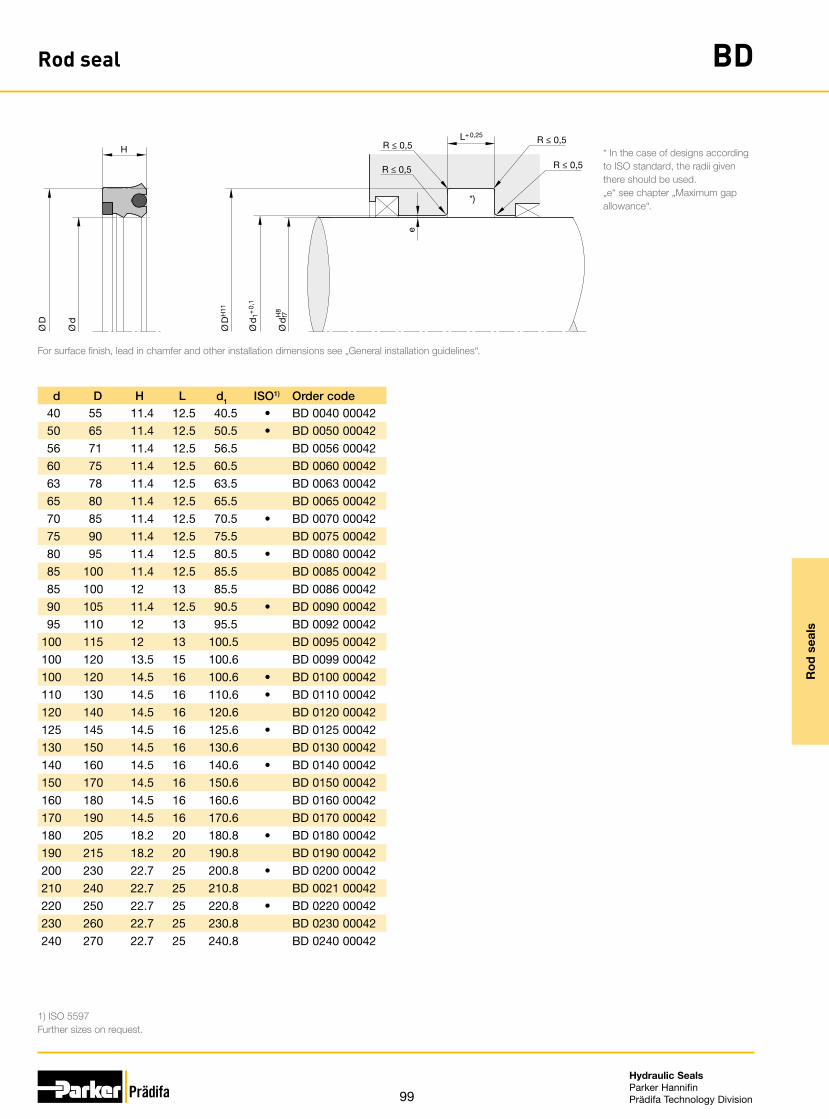
99
Hydraulic SealsParker HannifinPrädifa Technology Division
Ro
d s
eals
Rod seal BD
Ø D
H11
H8
Ø d
f7
L+ 0,25
H
*)
R ≤ 0,5
R ≤ 0,5
Ø d
1+ 0
,1
e
R ≤ 0,5
R ≤ 0,5
Ø D
Ø d
For surface finish, lead in chamfer and other installation dimensions see „General installation guidelines“.
* In the case of designs according to ISO standard, the radii given there should be used.„e“ see chapter „Maximum gap allowance“.
1) ISO 5597Further sizes on request.
d, D, H, L, d1, ISO1) Order code40 55 11.4 12.5 40.5 • BD 0040 0004250 65 11.4 12.5 50.5 • BD 0050 0004256 71 11.4 12.5 56.5 BD 0056 0004260 75 11.4 12.5 60.5 BD 0060 0004263 78 11.4 12.5 63.5 BD 0063 0004265 80 11.4 12.5 65.5 BD 0065 0004270 85 11.4 12.5 70.5 • BD 0070 0004275 90 11.4 12.5 75.5 BD 0075 0004280 95 11.4 12.5 80.5 • BD 0080 0004285 100 11.4 12.5 85.5 BD 0085 0004285 100 12 13 85.5 BD 0086 0004290 105 11.4 12.5 90.5 • BD 0090 0004295 110 12 13 95.5 BD 0092 00042
100 115 12 13 100.5 BD 0095 00042100 120 13.5 15 100.6 BD 0099 00042100 120 14.5 16 100.6 • BD 0100 00042110 130 14.5 16 110.6 • BD 0110 00042120 140 14.5 16 120.6 BD 0120 00042125 145 14.5 16 125.6 • BD 0125 00042130 150 14.5 16 130.6 BD 0130 00042140 160 14.5 16 140.6 • BD 0140 00042150 170 14.5 16 150.6 BD 0150 00042160 180 14.5 16 160.6 BD 0160 00042170 190 14.5 16 170.6 BD 0170 00042180 205 18.2 20 180.8 • BD 0180 00042190 215 18.2 20 190.8 BD 0190 00042200 230 22.7 25 200.8 • BD 0200 00042210 240 22.7 25 210.8 BD 0021 00042220 250 22.7 25 220.8 • BD 0220 00042230 260 22.7 25 230.8 BD 0230 00042240 270 22.7 25 240.8 BD 0240 00042

100
Hydraulic SealsParker HannifinPrädifa Technology Division
Ro
d s
eals
Rod seal BU
The profile BU Ultrathan® rod seal is a compact seal with an integrated anti-extrusion ring. A typical application of this seal profile is its use as a buffer seal in sealing sys-tems often found on construction machinery cylinders. These cylinders operate under extreme conditions where pressures up to 1000 bar are not unusual.The Ultrathan® rod seal profile BU is used to protect the secondary seal from this load. Due to its special form the seal is in a position to transfer pressure, which develops between the primary and secondary seal, back into the system. Single as well as tan-dem configurations of this seal profile are possible.
• Enhanced sealing performance in non-pressurized conditions.
• Robust seal profile for harshest operat-ing conditions.
• Extreme wear resistance.• Insensitive to extreme pressure peaks.• Extremely high extrusion resistance.• Excellent media resistance in case of
suitable compound selection.• Suitable compounds available for
special requirements of the chemical process industry.
• Suitable compounds available for spe-cial requirements of the food processing industry.
• Dimensions according to ISO 5597.• Dimensions according to ISO 7425-2.• Short axial assembly length.• Installation in closed and undercut
housings.• Additional sizes of machined products
available on short notice.
Range of applicationPrimarily for sealing cylinders in mobile hydraulics.
Operating pressure ≤ 500 bar
Pressure peaks ≤ 1000 bar
Operating temperature -35 °C to +110 °C
Sliding speed ≤ 0.5 m/s
Media Hydraulic oils based on mineral oil
CompoundsThe compound Ultrathan® P5008 is a Parker material based on polyurethane with a Shore A hardness of approx. 93.Back-up ring compound: W5019
InstallationThe seals should have an axial clearance (see columns H and L). To avoid damage at the sealing lips, the seals should not be pulled over sharp edges during installation.Normally these seals may be snapped into closed grooves. Where access is restricted special assembly tools may be required. Proposals for the design of such tools will be provided on request. For gap sizes see chapter “Maximum Gap Allowance”.
In case of special operating conditions (specific pressure loads, temperature, speed, use in water, HFA, HFB fluids etc.), please contact our consultancy service for a selection of the material and design best suit-ing your particular application requirements.

101
Hydraulic SealsParker HannifinPrädifa Technology Division
Ro
d s
eals
Rod seal BU
R*
R*
R*
R*
Ø D
H11
H8
Ø d
f7
L+ 0,2
H
Ø d
1+ 0
,1
Ø ≤ 63: R* ≤ 0,5Ø ≥ 63: R* ≤ 0,9
Ø D
Ø d
For surface finish, lead in chamfer and other installation dimensions see „General installation guidelines“.
1) Standard sizes for housings according to ISO 5597.2) Standard sizes for housings according to ISO 7425-2.Further sizes on request.
d, D, H, L, d1, ISO1) ISO2) Order code55 70 8.5 9.5 55.5 BU 0055 0006056 71 8.5 9.5 56.5 • BU 0056 0060060 75 8.5 9.5 60.5 BU 0060 0060060 75.1 6.1 6.3 60.5 BU 0061 0065663 78.1 6.1 6.3 63.4 BU 0063 0065665 80 8.5 9.5 65.4 BU 0065 0060065 80.5 6.1 6.3 65.4 • BU 0066 0065670 85 8.5 9.5 70.5 • BU 0070 0060070 85.1 6.1 6.3 70.5 BU 0071 0065675 90 8.5 9.5 75.5 BU 0075 0060080 95 8.5 9.5 80.5 • BU 0080 0060080 95.1 6.1 6.3 80.5 BU 0084 0065680 95.5 6.1 6.3 80.4 • BU 0082 0065685 100.5 6.1 6.3 85.4 • BU 0085 0065690 105 8.5 9.5 90.5 • BU 0090 0060090 105.5 6.1 6.3 90.4 • BU 0091 0065695 110.5 6.1 6.3 95.4 • BU 0094 00656
100 115.5 6.1 6.3 100.4 • BU 0104 00656100 120 11.4 12.5 100.6 • BU 0100 00600110 125.5 6.1 6.3 110.4 • BU 0118 00656110 130 11.4 12.5 110.6 • BU 0110 00600120 140 11.4 12.5 120.6 • BU 0120 00600130 150 14.5 16 130.6 BU 0130 00600140 160 14.5 16 140.6 • BU 0140 00600150 170 14.5 16 150.6 • BU 0150 00600160 180 14.5 16 160.6 BU 0160 00600170 190 10.3 11 170.6 BU 0170 00656180 205 14.5 16 180.8 • BU 0180 00600200 225 14.5 16 200.8 • BU 0200 00600220 250 18.2 20 220.8 • BU 0220 00600250 280 18.2 20 250.8 • BU 0250 00600280 310 18.2 20 280.8 BU 0280 00657

102
Hydraulic SealsParker HannifinPrädifa Technology Division
Pis
ton
seal
s

103
Hydraulic SealsParker HannifinPrädifa Technology Division
Pis
ton
seal
s
Piston seals
Profile cross-section Profile reference Pressure
max. (bar) Page
Piston seals
C2 160 104
KR 300 107
B7 400 110
OE 400 113
OG 400 118
ZW 400 123
OK 800 126

104
Hydraulic SealsParker HannifinPrädifa Technology Division
Pis
ton
seal
s
Piston seal C2
The profile C2 piston seal meets the requirements of the manufacturers of hydraulic and pneumatic equipment for seals with the smallest possible housings. Although cross-sections and heights are very small the sealing performance is excellent.
Extremely low friction is experienced because of the short contact to the sealing sur-face area. Because of the special design, back-up rings or brackets are not required.
Use in pneumatic equipment is only possible when consistent supply of lubricant such as oiled air is assured. For installation in non-lubricated pneumatic systems (dry air) we recommend our profile E4 which fits into the same housings.
• Good wear resistance.• Easier installation.• Suitable for fully automatic installation.• Assembly on one-part piston is pos-
sible.• High temperature resistance in case of
suitable compound selection.• Excellent media resistance in case of
suitable compound selection.• Suitable compounds available for
special requirements of the chemical process industry.
• Suitable compounds available for spe-cial requirements of the food processing industry.
• Installation in closed and undercut housings.
Range of applicationEspecially recommended for pistons in hydraulic and pneumatic cylinders.
Operating pressure 1)
Hydraulics ≤ 160 bar
Pneumatics ≤ 16 bar
Operating temperature
Hydraulics -25 °C to +100 °C
Pneumatics -25 °C to +80 °C
Sliding speed ≤ 0.5 m/s
1) Dependent upon cross-section and compound.
CompoundsStandard: N3584, NBR compound (≈ 85 Shore A).For low temperatures: N8613, NBR compound (≈ 80 Shore A).For high temperatures: V3664, FKM compound (≈ 85 Shore A).
InstallationThe profile C2 piston seals are manufactured undersized in relation to the nominal di-mensions. Only after installation will the sealing lip diameter have the desired dimen-sions. This lip seal may easily be snapped into the grooves. Care should be taken that the seals are not pulled over sharp edges.In the case of double-acting pistons, pressure peaks should be avoided. In such cases, sealing elements with larger cross-sections or other profiles with header rings should be used.
In case of special operating conditions (specific pressure loads, temperature, speed, use in water, HFA, HFB fluids etc.), please contact our consultancy service for a selection of the material and design best suit-ing your particular application requirements.

105
Hydraulic SealsParker HannifinPrädifa Technology Division
Pis
ton
seal
s
Piston seal C2
Ø D
H11
Ø d
h9
Ø d
1
Ø D
Ø d
L+ 0,2
H
R ≤ 0,2
R ≤ 0,2
e
R ≤ 0,2
R ≤ 0,2
For surface finish, lead in chamfer and other installation dimensions see „General installation guidelines“.
„e“ see chapter „Maximum gap allowance“.d1 = minimum piston diameter on pressure side.
Further sizes on request.
D, d, H, L, d1, Order code4 1.5 1.7 2 3 C2 0010 N35845 2 2.2 2.5 4 C2 0014 N35846 2.5 2 2.3 4.5 C2 0023 N35846 3 3 3.5 5 C2 0025 N35847.5 4 2 2.3 6 C2 0033 N35848 3 3.5 4 5.5 C2 0035 N35848 5 4 4.5 7 C2 0045 N35849.5 4.5 3.5 4 7 C2 0065 N3584
10 3 4 4.5 6.5 C2 1010 N358410 5 3.5 4 7.5 C2 1020 N358410 6 4.2 4.7 8 C2 1029 N358411 6 4 4.5 8.5 C2 1035 N358412 6 4 4.5 9 C2 1040 N358412 8 3 3.5 10 C2 1045 N358413 7 4 4.5 10 C2 1055 N358413.5 8 4 4.5 11 C2 1058 N358414 6 5.5 6 10 C2 1063 N358414 8 4 4.5 11 C2 1066 N358415 7 5.5 6 11 C2 1070 N358416 8 5.5 6 12 C2 1080 N358416 10 4 4.5 13 C2 1083 N358416 10 6 6.5 13 C2 1086 N358417.5 11.7 3 3.5 14.8 C2 1088 N358418 10 5 5.5 14 C2 1091 N357118 10 5.5 6 14 C2 1092 N358418 12 4.2 4.7 15 C2 1093 N358419.05 10.5 5.5 6 15 C2 1097 N358420 10 7 7.5 15 C2 2005 N358420 12 5.5 6 16 C2 2010 N358420 14 4.2 4.7 17 C2 2012 N358422 14 5.5 6 18 C2 2020 N358424 16 5.5 6 20 C2 2030 N358425 17 5.5 6 21 C2 2040 N358426 18 5.5 6 22 C2 2050 N3584
D, d, H, L, d1, Order code28 18 8 8.5 23 C2 2060 N358428 20 5.5 6 24 C2 2065 N358430 18 8 8.5 24 C2 3010 N358430 20 7 7.5 25 C2 3015 N358430 22 5.5 6 26 C2 3018 N358432 22 5 5.5 27 C2 3025 N358432 22 7 7.5 27 C2 3030 N358432 24 5.5 6 28 C2 3035 N358435 25 7 7.5 30 C2 3050 N358436 26 7 7.5 31 C2 3055 N358437 21 12 13 29 C2 3060 N358437 29 5.5 6 33 C2 3063 N358438 28 7 7.5 33 C2 3065 N358439.69 26.99 6.35 6.85 33.5 C2 3093 N358440 30 7 7.5 35 C2 4005 N358440 32 5.5 6 36 C2 4010 N358445 35 7 7.5 40 C2 4035 N358445 37 6 6.5 41 C2 4047 N358446 36 7 7.5 41 C2 4045 N358448 40 5.5 6 44 C2 4065 N358450 36 10 11 43 C2 5005 N358450 40 7 7.5 45 C2 5010 N358450 42 8 8.5 46 C2 5012 N358450.8 41.28 7.93 8.43 51 C2 5016 N358452 36 12 13 44 C2 5020 N358452 42 7 7.5 48 C2 5025 N358455 45 7 7.5 50 C2 5045 N358460 40 12 13 50 C2 6005 N358460 50 7 7.5 55 C2 6010 N358460 50 10 11 55 C2 6011 N358462 46 12 13 52 C2 6020 N358462 47 10 11 51.5 C2 6023 N358462 52 7 7.5 57 C2 6028 N358463 45 12 13 54 C2 6040 N3584
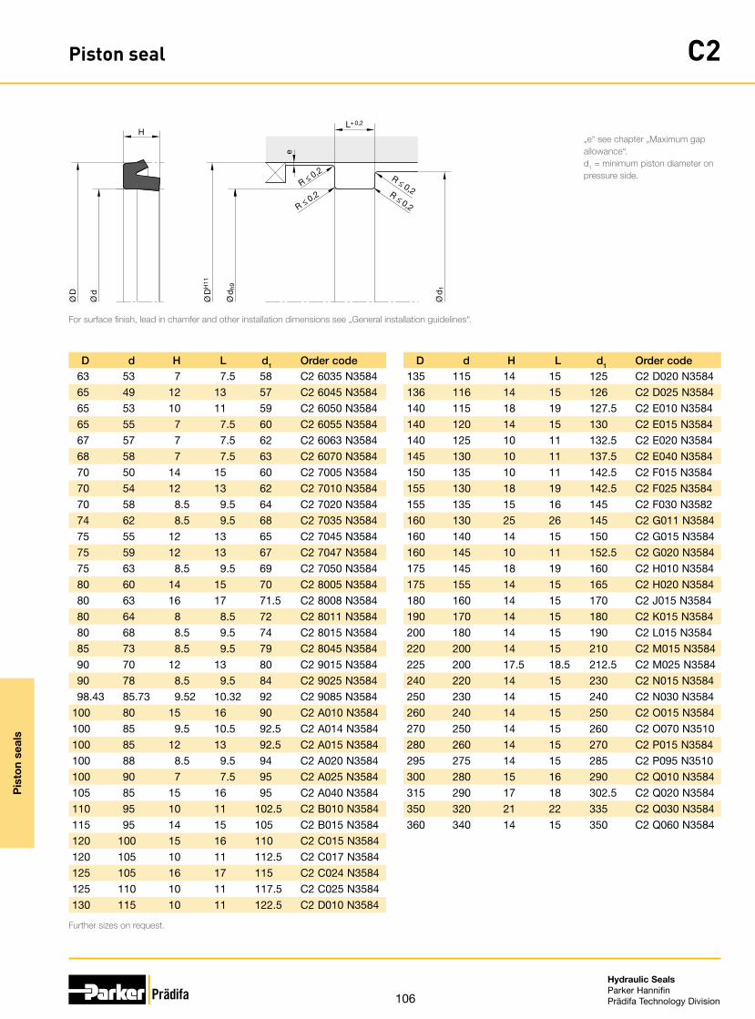
106
Hydraulic SealsParker HannifinPrädifa Technology Division
Pis
ton
seal
s
Piston seal C2
Ø D
H11
Ø d
h9
Ø d
1
Ø D
Ø d
L+ 0,2
H
R ≤ 0,2
R ≤ 0,2
e
R ≤ 0,2
R ≤ 0,2
For surface finish, lead in chamfer and other installation dimensions see „General installation guidelines“.
„e“ see chapter „Maximum gap allowance“.d1 = minimum piston diameter on pressure side.
Further sizes on request.
D, d, H, L, d1, Order code63 53 7 7.5 58 C2 6035 N358465 49 12 13 57 C2 6045 N358465 53 10 11 59 C2 6050 N358465 55 7 7.5 60 C2 6055 N358467 57 7 7.5 62 C2 6063 N358468 58 7 7.5 63 C2 6070 N358470 50 14 15 60 C2 7005 N358470 54 12 13 62 C2 7010 N358470 58 8.5 9.5 64 C2 7020 N358474 62 8.5 9.5 68 C2 7035 N358475 55 12 13 65 C2 7045 N358475 59 12 13 67 C2 7047 N358475 63 8.5 9.5 69 C2 7050 N358480 60 14 15 70 C2 8005 N358480 63 16 17 71.5 C2 8008 N358480 64 8 8.5 72 C2 8011 N358480 68 8.5 9.5 74 C2 8015 N358485 73 8.5 9.5 79 C2 8045 N358490 70 12 13 80 C2 9015 N358490 78 8.5 9.5 84 C2 9025 N358498.43 85.73 9.52 10.32 92 C2 9085 N3584
100 80 15 16 90 C2 A010 N3584100 85 9.5 10.5 92.5 C2 A014 N3584100 85 12 13 92.5 C2 A015 N3584100 88 8.5 9.5 94 C2 A020 N3584100 90 7 7.5 95 C2 A025 N3584105 85 15 16 95 C2 A040 N3584110 95 10 11 102.5 C2 B010 N3584115 95 14 15 105 C2 B015 N3584120 100 15 16 110 C2 C015 N3584120 105 10 11 112.5 C2 C017 N3584125 105 16 17 115 C2 C024 N3584125 110 10 11 117.5 C2 C025 N3584130 115 10 11 122.5 C2 D010 N3584
D, d, H, L, d1, Order code135 115 14 15 125 C2 D020 N3584136 116 14 15 126 C2 D025 N3584140 115 18 19 127.5 C2 E010 N3584140 120 14 15 130 C2 E015 N3584140 125 10 11 132.5 C2 E020 N3584145 130 10 11 137.5 C2 E040 N3584150 135 10 11 142.5 C2 F015 N3584155 130 18 19 142.5 C2 F025 N3584155 135 15 16 145 C2 F030 N3582160 130 25 26 145 C2 G011 N3584160 140 14 15 150 C2 G015 N3584160 145 10 11 152.5 C2 G020 N3584175 145 18 19 160 C2 H010 N3584175 155 14 15 165 C2 H020 N3584180 160 14 15 170 C2 J015 N3584190 170 14 15 180 C2 K015 N3584200 180 14 15 190 C2 L015 N3584220 200 14 15 210 C2 M015 N3584225 200 17.5 18.5 212.5 C2 M025 N3584240 220 14 15 230 C2 N015 N3584250 230 14 15 240 C2 N030 N3584260 240 14 15 250 C2 O015 N3584270 250 14 15 260 C2 O070 N3510280 260 14 15 270 C2 P015 N3584295 275 14 15 285 C2 P095 N3510300 280 15 16 290 C2 Q010 N3584315 290 17 18 302.5 C2 Q020 N3584350 320 21 22 335 C2 Q030 N3584360 340 14 15 350 C2 Q060 N3584

107
Hydraulic SealsParker HannifinPrädifa Technology Division
Pis
ton
seal
s
Piston sealing set KR
The Ultrathan® piston sealing set profile KR complements the product range of dou-ble-acting piston seals (OE, OK) for installation housings according to ISO 7425/1 by a product which is preferably used in the pressure range up to a maximum of 300 bar. The seal components are a slide ring consisting of a newly developed polyurethane with improved sliding qualities and an especially high module and a leader element with rectangular cross-section made of an NBR-elastomere.
• Exceptionally high static and dynamic sealing performance.
• Good sealing performance in extremely small assembly conditions.
• Can also be used for single-acting ap-plications.
• Robust seal profile for harshest operat-ing conditions.
• Extreme wear resistance.• Long service life thanks to application-
optimized compounds.• Constantly low dynamic friction
throughout the part‘s service life.• Easy snap assembly on a single-part
piston.• Insensitive to pressure peaks.• Functional reliability at critical tempera-
tures.• High extrusion resistance.• Dimensions according to ISO 7425-1.• Short axial assembly length.• Installation in closed and undercut
housings.
Range of applicationThe KR profile is suitable for use in all standard industrial cylinders as well as in farm-ing equipment, light construction machinery and mobile devices. Due to the excep-tionally high dynamic sealing performance, it is particularly suited for leakage-critical applications.
Operating pressure ≤ 300 bar
Operating temperature -35 °C to +110 °C
Sliding speed ≤ 0.5 m/s
CompoundsSlide ring: Ultrathan® P5062, modified polyurethane with a hardness of approximately 55 Shore D.Expander ring: NB078, NBR-elastomer with a hardness of approximately 80 Shore A.
InstallationThe installation groove must be carefully deburred and cleaned. The cylinder bore must have a leading edge chamfer. Profile KR can be snapped into closed grooves.
In case of special operating conditions (specific pressure loads, temperature, speed, use in water, HFA, HFB fluids etc.), please contact our consultancy service for a selection of the material and design best suit-ing your particular application requirements.
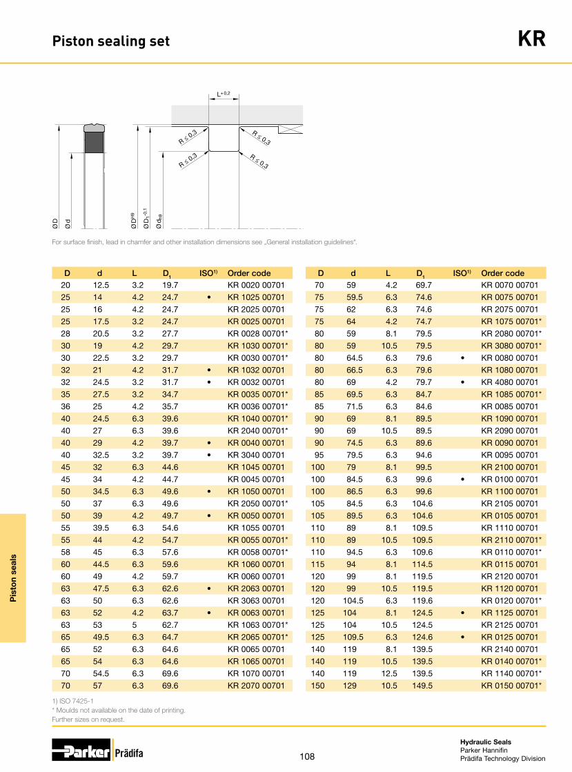
108
Hydraulic SealsParker HannifinPrädifa Technology Division
Pis
ton
seal
s
Piston sealing set KR
L+ 0,2
R ≤ 0,3
R ≤ 0,3
R ≤ 0,3
R ≤ 0,3
Ø D
H9
Ø d
h9
Ø D
1-0,1
Ø d
Ø D
For surface finish, lead in chamfer and other installation dimensions see „General installation guidelines“.
1) ISO 7425-1* Moulds not available on the date of printing.Further sizes on request.
D, d, L, D1, ISO1) Order code20 12.5 3.2 19.7 KR 0020 0070125 14 4.2 24.7 • KR 1025 0070125 16 4.2 24.7 KR 2025 0070125 17.5 3.2 24.7 KR 0025 0070128 20.5 3.2 27.7 KR 0028 00701*30 19 4.2 29.7 KR 1030 00701*30 22.5 3.2 29.7 KR 0030 00701*32 21 4.2 31.7 • KR 1032 0070132 24.5 3.2 31.7 • KR 0032 0070135 27.5 3.2 34.7 KR 0035 00701*36 25 4.2 35.7 KR 0036 00701*40 24.5 6.3 39.6 KR 1040 00701*40 27 6.3 39.6 KR 2040 00701*40 29 4.2 39.7 • KR 0040 0070140 32.5 3.2 39.7 • KR 3040 0070145 32 6.3 44.6 KR 1045 0070145 34 4.2 44.7 KR 0045 0070150 34.5 6.3 49.6 • KR 1050 0070150 37 6.3 49.6 KR 2050 00701*50 39 4.2 49.7 • KR 0050 0070155 39.5 6.3 54.6 KR 1055 0070155 44 4.2 54.7 KR 0055 00701*58 45 6.3 57.6 KR 0058 00701*60 44.5 6.3 59.6 KR 1060 0070160 49 4.2 59.7 KR 0060 0070163 47.5 6.3 62.6 • KR 2063 0070163 50 6.3 62.6 KR 3063 0070163 52 4.2 63.7 • KR 0063 0070163 53 5 62.7 KR 1063 00701*65 49.5 6.3 64.7 KR 2065 00701*65 52 6.3 64.6 KR 0065 0070165 54 6.3 64.6 KR 1065 0070170 54.5 6.3 69.6 KR 1070 0070170 57 6.3 69.6 KR 2070 00701
D, d, L, D1, ISO1) Order code70 59 4.2 69.7 KR 0070 0070175 59.5 6.3 74.6 KR 0075 0070175 62 6.3 74.6 KR 2075 0070175 64 4.2 74.7 KR 1075 00701*80 59 8.1 79.5 KR 2080 00701*80 59 10.5 79.5 KR 3080 00701*80 64.5 6.3 79.6 • KR 0080 0070180 66.5 6.3 79.6 KR 1080 0070180 69 4.2 79.7 • KR 4080 0070185 69.5 6.3 84.7 KR 1085 00701*85 71.5 6.3 84.6 KR 0085 0070190 69 8.1 89.5 KR 1090 0070190 69 10.5 89.5 KR 2090 0070190 74.5 6.3 89.6 KR 0090 0070195 79.5 6.3 94.6 KR 0095 00701
100 79 8.1 99.5 KR 2100 00701100 84.5 6.3 99.6 • KR 0100 00701100 86.5 6.3 99.6 KR 1100 00701105 84.5 6.3 104.6 KR 2105 00701105 89.5 6.3 104.6 KR 0105 00701110 89 8.1 109.5 KR 1110 00701110 89 10.5 109.5 KR 2110 00701*110 94.5 6.3 109.6 KR 0110 00701*115 94 8.1 114.5 KR 0115 00701120 99 8.1 119.5 KR 2120 00701120 99 10.5 119.5 KR 1120 00701120 104.5 6.3 119.6 KR 0120 00701*125 104 8.1 124.5 • KR 1125 00701125 104 10.5 124.5 KR 2125 00701125 109.5 6.3 124.6 • KR 0125 00701140 119 8.1 139.5 KR 2140 00701140 119 10.5 139.5 KR 0140 00701*140 119 12.5 139.5 KR 1140 00701*150 129 10.5 149.5 KR 0150 00701*

109
Hydraulic SealsParker HannifinPrädifa Technology Division
Pis
ton
seal
s
Piston sealing set KR
L+ 0,2
R ≤ 0,3
R ≤ 0,3
R ≤ 0,3
R ≤ 0,3
Ø D
H9
Ø d
h9
Ø D
1-0,1
Ø d
Ø D
For surface finish, lead in chamfer and other installation dimensions see „General installation guidelines“.
1) ISO 7425-1* Moulds not available on the date of printing.Further sizes on request.
D, d, L, D1, ISO1) Order code160 139 8.1 159.5 • KR 0160 00701180 159 8.1 179.5 KR 0180 00701*200 175 12.5 199.5 • KR 1200 00701*200 179 8.1 199.5 • KR 0200 00701

110
Hydraulic SealsParker HannifinPrädifa Technology Division
Pis
ton
seal
s
Piston seal B7
The profile B7 Ultrathan® piston seal is a lipseal which fits tightly in the groove. This seal may be used for all applications where the physical properties of normal or fabric reinforced elastomers are insufficient.
• Robust seal profile for harshest operat-ing conditions.
• Extreme wear resistance.• Easier installation.• Suitable for fully automatic installation.• Assembly on one-part piston is pos-
sible.• Insensitive to pressure peaks.• High extrusion resistance.• Excellent media resistance in case of
suitable compound selection.• Suitable compounds available for
special requirements of the chemical process industry.
• Suitable compounds available for spe-cial requirements of the food processing industry.
• Dimensions according to ISO 5597.• Installation in closed and undercut
housings.• Additional sizes of machined products
available on short notice.
Range of applicationMainly for the sealing of pistons in heavy duty applications in mobile and stationary hydraulics.
Operating pressure ≤ 400 bar
Operating temperature -35 °C to +110 °C
Sliding speed ≤ 0.5 m/s
Media Hydraulic oils based on mineral oil
CompoundsThe Ultrathan® P5008 compound is a Parker material based on polyurethane with a hardness of approx. 93 Shore A. Its main advantages in comparison with other poly-urethane materials currently available on the market are the increased heat resistance and the lower compression set.For media containing water, we recommend our hydrolysis-resistant polyurethane compound P5001.
InstallationThe seals should have an axial clearance (see columns H and L). To avoid damage at the sealing lips, the seals should not be pulled over sharp edges during installation.Normally these seals may be snapped into closed grooves. Where access is restricted special assembly tools may be required. Proposals for the design of such tools will be provided on request.
In case of special operating conditions (specific pressure loads, temperature, speed, use in water, HFA, HFB fluids etc.), please contact our consultancy service for a selection of the material and design best suit-ing your particular application requirements.

111
Hydraulic SealsParker HannifinPrädifa Technology Division
Pis
ton
seal
s
Piston seal B7
R 1
R1
Ø D
H9
L+ 0,25
H
Ø d
h9
Ø D
Ø d
e
R2 ≤ 0,2R 2
≤ 0,
2
**)
Ø < 100: R1 ≤ 0,3Ø ≥ 100: R1 ≤ 0,8
For surface finish, lead in chamfer and other installation dimensions see „General installation guidelines“.
** In the case of designs according to ISO standard, the radii given there should be used.„e“ see chapter „Maximum gap allowance“.
1) For housings according to ISO 5597 for ISO 6020-2 cylinders.2) Standard sizes for housings according to ISO 5597.Further sizes on request.
D, d, H, L, ISO1) ISO2) Order code15 10 4.2 4.7 B7 1504 P500816 8 5.7 6.3 • B7 1608 P500816 10 5.7 6.3 B7 1610 P500820 12 4.2 4.7 B7 2011 P500820 12 5.7 6.3 • B7 2012 P500822 12 8 9 B7 2212 P500824 16 5.7 6.3 B7 2416 P500825 15 7.3 8 • B7 2015 P500825 17 4.5 5 • B7 2516 P500825 17 5.7 6.3 • B7 2517 P500825 18 5 5.6 • B7 2520 P500827 20 7 8 B7 2720 P500828 20 7 8 B7 2810 P500832 22 7.3 8 • B7 3222 P500832 24 5.7 6.3 • B7 3224 P500832 25 5 5.6 • B7 3226 P500834 22 8.5 9.5 B7 3422 P500835 25 6 6.8 B7 3524 P500835 25 7.3 8 B7 3525 P500838.1 30.1 5.7 6.3 B7 3810 P500839 29 7.3 8 B7 3909 P500840 28 10 11 B7 4018 P500840 30 7.3 8 • B7 4030 P500840 30 10 11 B7 4031 P500840 32 5.7 6.3 • • B7 4032 P500840 33 8 9 B7 4033 P500843 33 7.3 8 B7 4304 P500845 35 7.3 8 B7 4535 P500850 35 10 11 B7 5010 P500850 35 11.4 12.5 • B7 5035 P500850 40 7.3 8 • B7 5040 P500850 40 10 11 B7 5041 P500850 42 5.7 6.3 • B7 5016 P500850.8 41.17 6.2 7 B7 5043 P5008
D, d, H, L, ISO1) ISO2) Order code52 42 7.3 8 B7 5209 P500854 44 5.5 6.1 B7 5405 P500854 44 7.3 8 B7 5409 P500855 45 7.3 8 B7 5545 P500857 41 11.4 12.5 B7 5703 P500860 50 7.3 8 B7 6050 P500860 50 10 11 B7 6009 P500863 48 8.6 9.5 • B7 6032 P500863 48 11.4 12.5 • B7 6348 P500863 53 7.3 8 • B7 6353 P500863 55 5.7 6.3 • B7 6355 P500865 55 7.3 8 B7 6055 P500867 57 7.3 8 B7 6709 P500868 58 9.5 10.5 B7 6805 P500870 60 7.5 8.2 B7 7011 P500870 60 12 13 B7 7012 P500875 63 8.7 9.5 B7 7027 P500880 60 14.5 16 • B7 8060 P500880 65 8.6 9.5 • B7 8008 P500880 65 11.4 12.5 • B7 8065 P500880 70 6.7 7.5 • B7 8010 P500880 70 12 13 B7 8011 P500890 75 11.4 12.5 B7 9075 P500895 80 11.4 12.5 B7 9580 P5008
100 80 14.5 16 • B7 A080 P5008100 85 11.4 12.5 • B7 A085 P5008100 88 9.5 10.5 B7 A088 P5008100 90 6.7 7.5 • B7 A090 P5008110 90 8 9 B7 B008 P5008110 90 15 16.5 B7 B004 P5008115 98 14.5 16 B7 B050 P5008120 105 11.4 12.5 B7 C120 P5008121 111.1 9.5 10.5 B7 C050 P5008125 100 18.2 20 • B7 C210 P5008

112
Hydraulic SealsParker HannifinPrädifa Technology Division
Pis
ton
seal
s
Piston seal B7
R 1
R1
Ø D
H9
L+ 0,25
H
Ø d
h9
Ø D
Ø d
e
R2 ≤ 0,2R 2
≤ 0,
2
**)
Ø < 100: R1 ≤ 0,3Ø ≥ 100: R1 ≤ 0,8
For surface finish, lead in chamfer and other installation dimensions see „General installation guidelines“.
** In the case of designs according to ISO standard, the radii given there should be used.„e“ see chapter „Maximum gap allowance“.
1) For housings according to ISO 5597 for ISO 6020-2 cylinders.2) Standard sizes for housings according to ISO 5597.Further sizes on request.
D, d, H, L, ISO1) ISO2) Order code125 105 14.5 16 • B7 C215 P5008125 110 9.6 10.6 • B7 C219 P5008145 115 18 20 B7 E050 P5008152.4 136.5 10 11 B7 F024 P5008160 135 18.2 20 • B7 G035 P5008160 140 14.5 16 • B7 G040 P5008180 150 18 20 B7 J004 P5008200 170 22.7 25 • B7 L007 P5008200 175 18.2 20 • B7 L010 P5008200 185 9.6 10.6 • B7 L013 P5008220 200 15 16.5 B7 M020 P5008240 215 15 16.5 B7 N010 P5008250 220 22.7 25 • B7 N120 P5008250 225 18.2 20 • B7 N125 P5008250 230 15 16.5 B7 N130 P5008270 240 22.5 25 B7 O170 P5008310 280 22.7 25 B7 Q028 P5008320 290 20 22 • B7 Q210 P5008

113
Hydraulic SealsParker HannifinPrädifa Technology Division
Pis
ton
seal
s
Slipper Seal® Piston sealing set OE
The double-acting piston sealing set profile OE consists of a PTFE piston sealing ring and an elastomer O-ring as a preloading element.
Profile OE is particularly suitable for double-acting pistons in control cylinders, in ser-vo-controlled systems, machine tools, quick acting and steering cylinders.
The material combination of the slipper ring (PTFE) and the O-ring (elastomer) makes this product suitable for a wide range of applications, especially for aggressive media and/or high temperatures. Multiple compounds can alternatively be selected accord-ing to the individual application profile.
• Good sealing performance in extremely small assembly conditions.
• Can also be used for single-acting ap-plications.
• Excellent wear resistance.• Minimal break-away and dynamic fric-
tion and no stick-slip tendency ensures uniform motion even at low speeds.
• Good energy efficiency due to low fric-tion.
• Assembly on one-part piston is pos-sible.
• Insensitive to pressure peaks.• High temperature resistance assured by
suitable O-ring compound selection.• High extrusion resistance.• Adaptable to nearly all media thanks to
high chemical resistance of the sealing ring and large O-ring compound selec-tion.
• Dimensions according to ISO 7425-1.• Short axial assembly length.• Installation in closed and undercut
housings.• Available in diameters from 4 to
3000 mm.• Additional sizes of machined products
available on short notice.
Range of applicationOperating pressure ≤ 400 bar
in case of reduced extrusion gap (H7/f7) and large cross sections
≤ 600 bar
Operating temperature -30 °C to +100 °C 1)
Sliding speed ≤ 4 m/s
1) With deviation from standard temperature range, please contact our consultancy service for adequate O-ring compound.
CompoundsSealing ring: Polon® 052, modified PTFE + 40 % bronze.O-ring: N0674, NBR elastomer with approx. 70 Shore A.
InstallationThis seal should only be used in combination with guiding elements (e.g. F3).
In case of special operating conditions (specific pressure loads, temperature, speed, use in water, HFA, HFB fluids etc.), please contact our consultancy service for a selection of the material and design best suit-ing your particular application requirements.
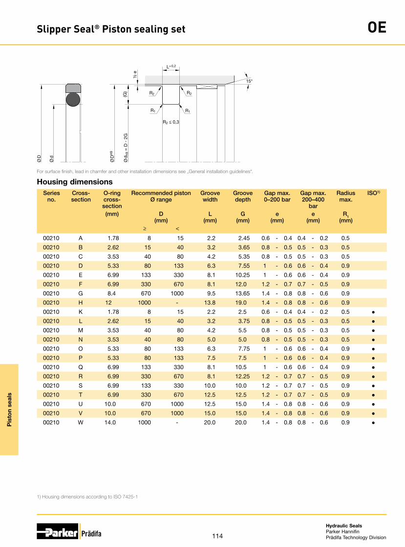
114
Hydraulic SealsParker HannifinPrädifa Technology Division
Pis
ton
seal
s
Slipper Seal® Piston sealing set OE
Ø d
h9 =
D -
2G
Ø D
H9
L+ 0,2
(G)
R1R1
R2
R2 ≤ 0,3
R2
15°
½ e
Ø D
Ø d
For surface finish, lead in chamfer and other installation dimensions see „General installation guidelines“.
1) Housing dimensions according to ISO 7425-1
Housing dimensionsSeries
no.Cross-section
O-ring cross-section
Recommended piston Ø range
Groove width
Groove depth
Gap max. 0–200 bar
Gap max. 200–400
bar
Radius max.
ISO1)
(mm) D (mm)
L (mm)
G (mm)
e (mm)
e (mm)
R1 (mm)
≥ <
00210 A 1.78 8 15 2.2 2.45 0.6 - 0.4 0.4 - 0.2 0.5
00210 B 2.62 15 40 3.2 3.65 0.8 - 0.5 0.5 - 0.3 0.5
00210 C 3.53 40 80 4.2 5.35 0.8 - 0.5 0.5 - 0.3 0.5
00210 D 5.33 80 133 6.3 7.55 1 - 0.6 0.6 - 0.4 0.9
00210 E 6.99 133 330 8.1 10.25 1 - 0.6 0.6 - 0.4 0.9
00210 F 6.99 330 670 8.1 12.0 1.2 - 0.7 0.7 - 0.5 0.9
00210 G 8.4 670 1000 9.5 13.65 1.4 - 0.8 0.8 - 0.6 0.9
00210 H 12 1000 - 13.8 19.0 1.4 - 0.8 0.8 - 0.6 0.9
00210 K 1.78 8 15 2.2 2.5 0.6 - 0.4 0.4 - 0.2 0.5 ●00210 L 2.62 15 40 3.2 3.75 0.8 - 0.5 0.5 - 0.3 0.5 ●00210 M 3.53 40 80 4.2 5.5 0.8 - 0.5 0.5 - 0.3 0.5 ●00210 N 3.53 40 80 5.0 5.0 0.8 - 0.5 0.5 - 0.3 0.5 ●00210 O 5.33 80 133 6.3 7.75 1 - 0.6 0.6 - 0.4 0.9 ●00210 P 5.33 80 133 7.5 7.5 1 - 0.6 0.6 - 0.4 0.9 ●00210 Q 6.99 133 330 8.1 10.5 1 - 0.6 0.6 - 0.4 0.9 ●00210 R 6.99 330 670 8.1 12.25 1.2 - 0.7 0.7 - 0.5 0.9 ●00210 S 6.99 133 330 10.0 10.0 1.2 - 0.7 0.7 - 0.5 0.9 ●00210 T 6.99 330 670 12.5 12.5 1.2 - 0.7 0.7 - 0.5 0.9 ●00210 U 10.0 670 1000 12.5 15.0 1.4 - 0.8 0.8 - 0.6 0.9 ●00210 V 10.0 670 1000 15.0 15.0 1.4 - 0.8 0.8 - 0.6 0.9 ●00210 W 14.0 1000 - 20.0 20.0 1.4 - 0.8 0.8 - 0.6 0.9 ●

115
Hydraulic SealsParker HannifinPrädifa Technology Division
Pis
ton
seal
s
Slipper Seal® Piston sealing set OE
Ø d
h9 =
D -
2G
Ø D
H9
L+ 0,2
(G)
R1R1
R2
R2 ≤ 0,3
R2
15°
½ e
Ø D
Ø d
For surface finish, lead in chamfer and other installation dimensions see „General installation guidelines“.
Ordering examplePiston diameter 80 mm
OE 0800 052 00211 D (80.0 x 64.5 x 6.3)
OE Profile
0800 Piston diameter × 10
052 Compound
00211 Series no. / compound code O-ring
00210 without O-ring
00211 N0674 (NBR) 70±5 Shore A -30 / +110 °C
00212 V0747 (FKM) 75±5 Shore A -25 / +200 °C
00213 N0756 (NBR) 75±5 Shore A -50 / +110 °C
00214 E0540 (EPDM) 80±5 Shore A -40 / +150 °C
00215 N3578 (NBR) 75±5 Shore A -30 / +110 °C
00216 N0552 (NBR) 90±5 Shore A -30 / +100 °C
00217 N1173 (HNBR) 70±5 Shore A -30 / +150 °C
D Cross-section
Please note: For certain applications, it might be convenient to use a non-standard cross-section – reduced or heavier. In these cases, please replace the standard cross-section code (in above example: „D“) by the one you require (for example „C“ or „E“).

116
Hydraulic SealsParker HannifinPrädifa Technology Division
Pis
ton
seal
s
Slipper Seal® Piston sealing set OE
Ø d
h9 =
D -
2G
Ø D
H9
L+ 0,2
(G)
R1R1
R2
R2 ≤ 0,3
R2
15°
½ e
Ø D
Ø d
For surface finish, lead in chamfer and other installation dimensions see „General installation guidelines“.
1) ISO 7425-1Further sizes on request.
Standard rangeSize Groove O-ring ISO1)
Ø D Ø d L No. CS ID
(mm) (mm) (mm) (mm) (mm)
0080 8 3.10 2.20 2-006 1.78 2.90
0100 10 5.10 2.20 2-008 1.78 4.47
0120 12 7.10 2.20 2-010 1.78 6.07
0150 15 7.50 3.20 2-109 2.62 7.59
0160 16 11 2.20 2-013 1.78 10.82 ●0160 16 8.50 3.20 2-109 2.62 7.59 ●0180 18 10.50 3.20 2-110 2.62 9.19
0200 20 15 2.20 2-015 1.78 14 ●0200 20 12.50 3.20 2-111 2.62 10.77 ●0220 22 14.50 3.20 2-113 2.62 13.94
0250 25 17.50 3.20 2-115 2.62 17.12 ●0250 25 14 4.20 2-207 3.53 13.87 ●0250 25 15 5 2-208 3.53 15.47 ●0280 28 20.50 3.20 2-116 2.62 18.72
0300 30 22.50 3.20 2-118 2.62 21.89
0320 32 24.50 3.20 2-119 2.62 23.47 ●0320 32 21 4.20 2-211 3.53 20.22 ●0320 32 22 5 2-212 3.53 21.82 ●0350 35 27.50 3.20 2-121 2.62 26.64
0400 40 32.50 3.20 2-124 2.62 31.42 ●0400 40 29 4.20 2-216 3.53 28.17 ●0400 40 30 5 2-217 3.53 29.74 ●0420 42 31 4.20 2-217 3.53 29.74
0450 45 34 4.20 2-219 3.53 32.92
0480 48 37 4.20 2-221 3.53 36.09
0500 50 39 4.20 2-222 3.53 37.69 ●0500 50 34.50 6.30 2-324 5.33 34.29 ●0500 50 35 7.50 2-324 5.33 34.29 ●0520 52 41 4.20 2-223 3.53 40.87
0550 55 44 4.20 2-224 3.53 44.04
Size Groove O-ring ISO1)
Ø D Ø d L No. CS ID
(mm) (mm) (mm) (mm) (mm)
0600 60 49 4.20 2-225 3.53 47.22
0630 63 52 4.20 2-226 3.53 50.39 ●0630 63 47.50 6.30 2-328 5.33 46.99 ●0630 63 48 7.50 2-328 5.33 46.99 ●0650 65 54 4.20 2-227 3.53 53.57
0700 70 59 4.20 2-228 3.53 56.74
0800 80 69 4.20 2-232 3.53 69.44 ●0800 80 64.50 6.30 2-333 5.33 62.87 ●0850 85 69.50 6.30 2-335 5.33 69.22
0900 90 74.50 6.30 2-336 5.33 72.39
0950 95 79.50 6.30 2-338 5.33 78.74
1000 100 89 4.20 2-238 3.53 88.49 ●1000 100 84.50 6.30 2-339 5.33 81.92 ●1050 105 89.50 6.30 2-341 5.33 88.27
1100 110 94.50 6.30 2-343 5.33 94.62
1150 115 99.50 6.30 2-344 5.33 97.79
1200 120 104.50 6.30 2-346 5.33 104.14
1250 125 109.50 6.30 2-347 5.33 107.32 ●1250 125 104 8.10 6-392 6.99 99 ●1250 125 105 10 6-392 6.99 99 ●1300 130 114.50 6.30 2-349 5.33 113.67
1350 135 114 8.10 2-425 6.99 113.67
1400 140 119 8.10 2-426 6.99 116.84
1450 145 124 8.10 2-428 6.99 123.19
1500 150 129 8.10 2-429 6.99 126.37
1550 155 134 8.10 2-431 6.99 132.72
1600 160 144.50 6.30 2-358 5.33 142.24 ●1600 160 139 8.10 2-433 6.99 139.07 ●1600 160 135 12.50 2-431 6.99 132.72 ●1650 165 144 8.10 2-434 6.99 142.24

117
Hydraulic SealsParker HannifinPrädifa Technology Division
Pis
ton
seal
s
Slipper Seal® Piston sealing set OE
Ø d
h9 =
D -
2G
Ø D
H9
L+ 0,2
(G)
R1R1
R2
R2 ≤ 0,3
R2
15°
½ e
Ø D
Ø d
For surface finish, lead in chamfer and other installation dimensions see „General installation guidelines“.
1) ISO 7425-1Further sizes on request.
Size Groove O-ring ISO1)
Ø D Ø d L No. CS ID
(mm) (mm) (mm) (mm) (mm)
1700 170 149 8.10 2-436 6.99 148.59
1750 175 154 8.10 2-437 6.99 151.77
1800 180 159 8.10 2-438 6.99 158.12
1850 185 164 8.10 2-439 6.99 164.47
1900 190 169 8.10 2-439 6.99 164.47
1950 195 174 8.10 2-440 6.99 170.82
2000 200 184.50 6.30 2-366 5.33 183.52 ●2000 200 179 8.10 2-441 6.99 177.17 ●2000 200 175 12.50 2-440 6.99 170.82 ●2100 210 189 8.10 2-442 6.99 183.52
2200 220 199 8.10 2-444 6.99 196.22
2300 230 209 8.10 2-445 6.99 202.57
2400 240 219 8.10 2-446 6.99 215.27
2500 250 229 8.10 2-447 6.99 227.97 ●2500 250 225.50 8.10 2-447 6.99 227.97 ●2600 260 239 8.10 2-447 6.99 227.97
2700 270 249 8.10 2-448 6.99 240.67
2800 280 259 8.10 2-449 6.99 253.37
2900 290 269 8.10 2-450 6.99 266.07
3000 300 279 8.10 2-451 6.99 278.77
3100 310 289 8.10 2-451 6.99 278.77
3200 320 299 8.10 2-452 6.99 291.47 ●3200 320 295.50 8.10 2-452 6.99 291.47 ●3300 330 305.50 8.10 2-453 6.99 304.17
3400 340 315.50 8.10 2-453 6.99 304.17
3500 350 325.50 8.10 2-454 6.99 316.87
3600 360 335.50 8.10 2-455 6.99 329.57
3700 370 345.50 8.10 2-456 6.99 342.27
3800 380 355.50 8.10 2-457 6.99 354.97
3900 390 365.50 8.10 2-457 6.99 354.97
Size Groove O-ring ISO1)
Ø D Ø d L No. CS ID
(mm) (mm) (mm) (mm) (mm)
4000 400 375.50 8.10 2-458 6.99 367.67 ●4000 400 370 12.50 6-672 10 364 ●4000 400 360 20 6-895 14 359 ●4100 410 385.50 8.10 2-459 6.99 380.37
4200 420 395.50 8.10 2-460 6.99 393.07
4300 430 405.50 8.10 2-461 6.99 405.26
4400 440 415.50 8.10 2-461 6.99 405.26
4500 450 425.50 8.10 2-462 6.99 417.96
4600 460 435.50 8.10 2-463 6.99 430.66
4700 470 445.50 8.10 2-464 6.99 443.36
4800 480 455.50 8.10 2-465 6.99 456.06
4900 490 465.50 8.10 2-465 6.99 456.06
5000 500 475.50 8.10 2-466 6.99 468.76 ●5000 500 470 12.50 6-827 10 470 ●5200 520 495.50 8.10 2-468 6.99 494.16
5500 550 525.50 8.10 2-469 6.99 506.86
5700 570 545.50 8.10 2-470 6.99 532.26
6000 600 575.50 8.10 2-471 6.99 557.66
6200 620 595.50 8.10 2-472 6.99 582.68
6400 640 615.50 8.10 2-473 6.99 608.08
6500 650 622 9.50 - 8.40 635
7000 700 672 9.50 - 8.40 660
8000 800 772 9.50 - 8.40 770
9000 900 872 9.50 - 8.40 888

118
Hydraulic SealsParker HannifinPrädifa Technology Division
Pis
ton
seal
s
Slipper Seal® Piston sealing set OG
The single-acting piston sealing set profile OG consists of a PTFE piston sealing ring and an elastomer O-ring as a preloading element.
The asymmetrical cross-section of the slipper ring is designed for best drag oil perfor-mance during stroke in both directions.
Profile OG is particularly suitable for single-acting pistons in control cylinders, in servo controlled systems, machine tools, quick acting cylinders.
The material combination of the slipper ring (PTFE) and the O-ring (elastomer) makes this product suitable for a wide range of applications, especially for aggressive media and/or high temperatures. Multiple compounds can alternatively be selected accord-ing to the individual application profile.
• Good sealing performance in extremely small assembly conditions.
• Excellent wear resistance.• Minimal break-away and dynamic fric-
tion and no stick-slip tendency ensures uniform motion even at low speeds.
• Good energy efficiency due to low fric-tion.
• Insensitive to pressure peaks.• High temperature resistance assured by
suitable O-ring compound selection.• High extrusion resistance.• Adaptable to nearly all media thanks to
high chemical resistance of the sealing ring and large O-ring compound selec-tion.
• Dimensions according to ISO 7425-1.• Also available as double-acting version.• Short axial assembly length.• Installation in closed and undercut
housings.• Available in diameters from 4 to
3000 mm.• Additional sizes of machined products
available on short notice.
Range of applicationOperating pressure ≤ 400 bar
in case of reduced extrusion gap (H7/f7) and large cross sections
≤ 600 bar
Operating temperature -30 °C to +100 °C 1)
Sliding speed ≤ 4 m/s
1) With deviation from standard temperature range, please contact our consultancy service for adequate O-ring compound.
CompoundsSealing ring: Polon® 052, modified PTFE + 40 % bronze.O-ring: N0674, NBR elastomer with approx. 70 Shore A.
InstallationThis seal should only be used in combination with guiding elements (e.g. F3).
In case of special operating conditions (specific pressure loads, temperature, speed, use in water, HFA, HFB fluids etc.), please contact our consultancy service for a selection of the material and design best suit-ing your particular application requirements.

119
Hydraulic SealsParker HannifinPrädifa Technology Division
Pis
ton
seal
s
Slipper Seal® Piston sealing set OG
Ø d
h9 =
D -
2G
Ø D
H9
L+ 0,2
(G)
R1R1
R2
R2 ≤ 0,3
R2
15°
½ e
Ø D
Ø d
For surface finish, lead in chamfer and other installation dimensions see „General installation guidelines“.
1) Housing dimensions according to ISO 7425-1
Housing dimensionsSeries no. Cross-
sectionO-ring cross-section
Recommended piston Ø range
Groove width
Groove depth
Gap max. 0–200 bar
Gap max. 200–400 bar
Radius max.
ISO1)
(mm) D(mm)
L(mm)
G(mm)
e(mm)
e(mm)
R1(mm)
≥ <
00270 A 1.78 8 17 2.2 2.45 0.6 - 0.4 0.4 - 0.2 0.5
00270 B 2.62 17 27 3.2 3.65 0.8 - 0.5 0.5 - 0.3 0.5
00270 C 3.53 27 60 4.2 5.35 0.8 - 0.5 0.5 - 0.3 0.5
00270 D 5.33 60 200 6.3 7.55 1.0 - 0.6 0.6 - 0.4 0.9
00270 E 6.99 200 256 8.1 10.25 1.0 - 0.6 0.6 - 0.4 0.9
00270 F 6.99 256 670 8.1 12 1.2 - 0.7 0.7 - 0.5 0.9
00270 G 8.4 670 1000 9.5 13.65 1.4 - 0.8 0.8 - 0.6 0.9
00270 H 12 1000 - 13.8 19 1.4 - 0.8 0.8 - 0.6 0.9
00270 K 1.78 8 17 2.2 2.5 0.6 - 0.4 0.4 - 0.2 0.5 ●00270 L 2.62 17 27 3.2 3.75 0.8 - 0.5 0.5 - 0.3 0.5 ●00270 M 3.53 27 60 4.2 5.5 0.8 - 0.5 0.5 - 0.3 0.5 ●00270 N 3.53 27 60 5 5 0.8 - 0.5 0.5 - 0.3 0.5 ●00270 O 5.33 60 200 6.3 7.75 1.0 - 0.6 0.6 - 0.4 0.9 ●00270 P 5.33 60 200 7.5 7.5 1.0 - 0.6 0.6 - 0.4 0.9 ●00270 Q 6.99 200 256 8.1 10.5 1.0 - 0.6 0.6 - 0.4 0.9 ●00270 R 6.99 256 670 8.1 12.25 1.2 - 0.7 0.7 - 0.5 0.9 ●00270 S 6.99 200 256 10 10 1.2 - 0.7 0.7 - 0.5 0.9 ●00270 T 6.99 256 670 12.5 12.5 1.2 - 0.7 0.7 - 0.5 0.9 ●00270 U 10.00 670 1000 12.5 15 1.4 - 0.8 0.8 - 0.6 0.9 ●00270 V 10.00 670 1000 15 15 1.4 - 0.8 0.8 - 0.6 0.9 ●00270 W 14.00 1000 - 20 20 1.4 - 0.8 0.8 - 0.6 0.9 ●

120
Hydraulic SealsParker HannifinPrädifa Technology Division
Pis
ton
seal
s
Slipper Seal® Piston sealing set OG
Ø d
h9 =
D -
2G
Ø D
H9
L+ 0,2
(G)
R1R1
R2
R2 ≤ 0,3
R2
15°
½ e
Ø D
Ø d
For surface finish, lead in chamfer and other installation dimensions see „General installation guidelines“.
Ordering examplePiston diameter 80 mm
OG 0800 052 00271 D (80 × 64.9 × 6.3)
OG Profile
0800 Piston diameter × 10
052 Compound
00271 Series no. / compound code O-ring
00270 without O-ring
00271 N0674 (NBR) 70±5 Shore A -30 / +110 °C
00272 V0747 (FKM) 75±5 Shore A -25 / +200 °C
00273 N0756 (NBR) 75±5 Shore A -50 / +110 °C
00274 E0540 (EPDM) 80±5 Shore A -40 / +150 °C
00275 N3578 (NBR) 75±5 Shore A -30 / +110 °C
00276 N0552 (NBR) 90±5 Shore A -30 / +100 °C
00277 N1173 (HNBR) 70±5 Shore A -30 / +150 °C
D Cross-section
Please note: For certain applications, it might be convenient to use a non-standard cross-section – reduced or heavier. In these cases, please replace the standard cross-section code (in above example: „D“) by the one you require (for example „C“ or „E“).

121
Hydraulic SealsParker HannifinPrädifa Technology Division
Pis
ton
seal
s
Slipper Seal® Piston sealing set OG
Ø d
h9 =
D -
2G
Ø D
H9
L+ 0,2
(G)
R1R1
R2
R2 ≤ 0,3
R2
15°
½ e
Ø D
Ø d
For surface finish, lead in chamfer and other installation dimensions see „General installation guidelines“.
1) ISO 7425-1Further sizes on request.
Standard rangeSize Groove O-ring ISO1)
Ø D Ø d L No. CS ID
(mm) (mm) (mm) (mm) (mm)
0080 8 3.10 2.20 2-006 1.78 2.90
0100 10 5.10 2.20 2-008 1.78 4.47
0120 12 7.10 2.20 2-010 1.78 6.07
0150 15 7.50 3.20 2-109 2.62 7.59
0160 16 11 2.20 2-013 1.78 10.82 ●0160 16 8.50 3.20 2-109 2.62 7.59 ●0180 18 10.50 3.20 2-110 2.62 9.19
0200 20 15 2.20 2-015 1.78 14 ●0200 20 12.50 3.20 2-111 2.62 10.77 ●0220 22 14.50 3.20 2-113 2.62 13.94
0250 25 17.50 3.20 2-115 2.62 17.12 ●0250 25 14 4.20 2-207 3.53 13.87 ●0250 25 15 5 2-208 3.53 15.47 ●0280 28 20.50 3.20 2-116 2.62 18.72
0300 30 22.50 3.20 2-118 2.62 21.89
0320 32 24.50 3.20 2-119 2.62 23.47 ●0320 32 21 4.20 2-211 3.53 20.22 ●0320 32 22 5 2-212 3.53 21.82 ●0350 35 27.50 3.20 2-121 2.62 26.64
0400 40 32.50 3.20 2-124 2.62 31.42 ●0400 40 29 4.20 2-216 3.53 28.17 ●0400 40 30 5 2-217 3.53 29.74 ●0420 42 31 4.20 2-217 3.53 29.74
0450 45 34 4.20 2-219 3.53 32.92
0480 48 37 4.20 2-221 3.53 36.09
0500 50 39 4.20 2-222 3.53 37.69 ●0500 50 34.50 6.30 2-324 5.33 34.29 ●0500 50 35 7.50 2-324 5.33 34.29 ●0520 52 41 4.20 2-223 3.53 40.87
0550 55 44 4.20 2-224 3.53 44.04
Size Groove O-ring ISO1)
Ø D Ø d L No. CS ID
(mm) (mm) (mm) (mm) (mm)
0600 60 49 4.20 2-225 3.53 47.22
0630 63 52 4.20 2-226 3.53 50.39 ●0630 63 47.50 6.30 2-328 5.33 46.99 ●0630 63 48 7.50 2-328 5.33 46.99 ●0650 65 54 4.20 2-227 3.53 53.57
0700 70 59 4.20 2-228 3.53 56.74
0800 80 69 4.20 2-232 3.53 69.44 ●0800 80 64.50 6.30 2-333 5.33 62.87 ●0850 85 69.50 6.30 2-335 5.33 69.22
0900 90 74.50 6.30 2-336 5.33 72.39
0950 95 79.50 6.30 2-338 5.33 78.74
1000 100 89 4.20 2-238 3.53 88.49 ●1000 100 84.50 6.30 2-339 5.33 81.92 ●1050 105 89.50 6.30 2-341 5.33 88.27
1100 110 94.50 6.30 2-343 5.33 94.62
1150 115 99.50 6.30 2-344 5.33 97.79
1200 120 104.50 6.30 2-346 5.33 104.14
1250 125 109.50 6.30 2-347 5.33 107.32 ●1250 125 104 8.10 6-392 6.99 99 ●1250 125 105 10 6-392 6.99 99 ●1300 130 114.50 6.30 2-349 5.33 113.67
1350 135 114 8.10 2-425 6.99 113.67
1400 140 119 8.10 2-426 6.99 116.84
1450 145 124 8.10 2-428 6.99 123.19
1500 150 129 8.10 2-429 6.99 126.37
1550 155 134 8.10 2-431 6.99 132.72
1600 160 144.50 6.30 2-358 5.33 142.24 ●1600 160 139 8.10 2-433 6.99 139.07 ●1600 160 135 12.50 2-431 6.99 132.72 ●1650 165 144 8.10 2-434 6.99 142.24

122
Hydraulic SealsParker HannifinPrädifa Technology Division
Pis
ton
seal
s
Slipper Seal® Piston sealing set OG
Ø d
h9 =
D -
2G
Ø D
H9
L+ 0,2
(G)
R1R1
R2
R2 ≤ 0,3
R2
15°
½ e
Ø D
Ø d
For surface finish, lead in chamfer and other installation dimensions see „General installation guidelines“.
1) ISO 7425-1Further sizes on request.
Size Groove O-ring ISO1)
Ø D Ø d L No. CS ID
(mm) (mm) (mm) (mm) (mm)
1700 170 149 8.10 2-436 6.99 148.59
1750 175 154 8.10 2-437 6.99 151.77
1800 180 159 8.10 2-438 6.99 158.12
1850 185 164 8.10 2-439 6.99 164.47
1900 190 169 8.10 2-439 6.99 164.47
1950 195 174 8.10 2-440 6.99 170.82
2000 200 184.50 6.30 2-366 5.33 183.52 ●2000 200 179 8.10 2-441 6.99 177.17 ●2000 200 175 12.50 2-440 6.99 170.82 ●2100 210 189 8.10 2-442 6.99 183.52
2200 220 199 8.10 2-444 6.99 196.22
2300 230 209 8.10 2-445 6.99 202.57
2400 240 219 8.10 2-446 6.99 215.27
2500 250 229 8.10 2-447 6.99 227.97 ●2500 250 225.50 8.10 2-447 6.99 227.97 ●2600 260 239 8.10 2-447 6.99 227.97
2700 270 249 8.10 2-448 6.99 240.67
2800 280 259 8.10 2-449 6.99 253.37
2900 290 269 8.10 2-450 6.99 266.07
3000 300 279 8.10 2-451 6.99 278.77
3100 310 289 8.10 2-451 6.99 278.77
3200 320 299 8.10 2-452 6.99 291.47 ●3200 320 295.50 8.10 2-452 6.99 291.47 ●3300 330 305.50 8.10 2-453 6.99 304.17
3400 340 315.50 8.10 2-453 6.99 304.17
3500 350 325.50 8.10 2-454 6.99 316.87
3600 360 335.50 8.10 2-455 6.99 329.57
3700 370 345.50 8.10 2-456 6.99 342.27
3800 380 355.50 8.10 2-457 6.99 354.97
3900 390 365.50 8.10 2-457 6.99 354.97
Size Groove O-ring ISO1)
Ø D Ø d L No. CS ID
(mm) (mm) (mm) (mm) (mm)
4000 400 375.50 8.10 2-458 6.99 367.67 ●4000 400 370 12.50 6-672 10 364 ●4000 400 360 20 6-895 14 359 ●4100 410 385.50 8.10 2-459 6.99 380.37
4200 420 395.50 8.10 2-460 6.99 393.07
4300 430 405.50 8.10 2-461 6.99 405.26
4400 440 415.50 8.10 2-461 6.99 405.26
4500 450 425.50 8.10 2-462 6.99 417.96
4600 460 435.50 8.10 2-463 6.99 430.66
4700 470 445.50 8.10 2-464 6.99 443.36
4800 480 455.50 8.10 2-465 6.99 456.06
4900 490 465.50 8.10 2-465 6.99 456.06
5000 500 475.50 8.10 2-466 6.99 468.76 ●5000 500 470 12.50 6-827 10 470 ●5200 520 495.50 8.10 2-468 6.99 494.16
5500 550 525.50 8.10 2-469 6.99 506.86
5700 570 545.50 8.10 2-470 6.99 532.26
6000 600 575.50 8.10 2-471 6.99 557.66
6200 620 595.50 8.10 2-472 6.99 582.68
6400 640 615.50 8.10 2-473 6.99 608.08
6500 650 622 9.50 - 8.40 635
7000 700 672 9.50 - 8.40 660
8000 800 772 9.50 - 8.40 770
9000 900 872 9.50 - 8.40 888

123
Hydraulic SealsParker HannifinPrädifa Technology Division
Pis
ton
seal
s
Piston sealing set ZW
The profile ZW double-acting piston sealing set consists of an elastomer sealing com-ponent, two anti-extrusion and two angular guide rings.
• Good wear resistance.• Assembly on one-part piston is pos-
sible.• Installation in closed and undercut
housings.
Range of applicationSealing set for double-acting pistons in presses, drive cylinders, back-up and operat-ing cylinders for industrial and mobile hydraulics.
Operating pressure ≤ 400 bar
Operating temperature -35 °C to +100 °C
in HFA, HFB and HFC fluids +60 °C
Sliding speed ≤ 0.5 m/s
CompoundsRubber component: Highly wear-resistant NBR-compound NB078 with a hardness of 80 Shore A.Anti-extrusion rings: High-strength, wear-optimized polyester elastomer (W5035).Angular guide rings: Thermoplast for high pressure resistance even with increased temperatures (W5301).
InstallationSharp edges and burrs in the assembly area of the seal must be removed. Assembly is performed in the following sequence: „rubber seal, anti-extrusion rings, angular guide rings“. Ensure that the contact points (gaps) of the angular guide and anti-extrusion rings are arranged in staggering positions.
In case of special operating conditions (specific pressure loads, temperature, speed, use in water, HFA, HFB fluids etc.), please contact our consultancy service for a selection of the material and design best suit-ing your particular application requirements.

124
Hydraulic SealsParker HannifinPrädifa Technology Division
Pis
ton
seal
s
Piston sealing set ZW
a+ 0,1 a+ 0,1L+ 0,1
H+ 0,3
R ≤ 0,2
R ≤ 0,4
R ≤ 0,4
Ø D
H9
Ø d
h9
Ø d
1 h9
Ø d
2 h1
1
Ø d
Ø D
20° -
30°
For surface finish, lead in chamfer and other installation dimensions see „General installation guidelines“.
Further sizes on request.
D, d, L, H, d1, d2, a, Order code30 21 13.5 17.7 27 29 2.1 ZW 0030 0026032 22 15.5 20.7 28 31 2.6 ZW 0032 0026040 24 18.4 31.1 35.4 38.5 6.35 ZW 0040 0026040 26 15.5 20.7 36 39 2.6 ZW 1040 0026040 30 16.4 29.1 35.4 38.5 6.35 ZW 2040 0026045 35 16.4 29.1 40.4 43.5 6.35 ZW 2045 0026050 34 18.4 31.1 45.4 48.5 6.35 ZW 0050 0026050 34 20.5 26.7 46 49 3.1 ZW 1050 0026050 38 20.5 28.9 46 48.5 4.2 ZW 2050 0026055 39 18.4 31.1 50.36 53.5 6.35 ZW 0055 0026060 44 18.4 31.1 55.4 58.5 6.35 ZW 0060 0026060 44 20.5 26.7 56 59 3.1 ZW 1060 0026060 48 20.5 28.9 56 58.5 4.2 ZW 2060 0026063 47 18.4 31.1 58.4 61.5 6.35 ZW 0063 0026063 47 19.4 32.1 58.4 61.5 6.35 ZW 1063 0026063 47 20.5 26.7 59 62 3.1 ZW 2063 0026063 51 20.5 28.9 59 61.5 4.2 ZW 3063 0026065 49 20.5 26.7 61 64 3.1 ZW 0065 0026065 50 18.4 31.1 60.4 63.5 6.35 ZW 1065 0026070 50 22.4 35.1 64.2 68.3 6.35 ZW 0070 0026070 54 20.5 26.7 66 69 3.1 ZW 1070 0026070 58 20.5 28.9 66 68.5 4.2 ZW 2070 0026075 55 22.4 35.1 69.2 73.3 6.35 ZW 0075 0026080 60 22.4 35.1 74.15 78.3 6.35 ZW 0080 0026080 62 22.5 29.7 76 79 3.6 ZW 1080 0026080 66 22.5 32.9 76 78.5 5.2 ZW 2080 0026085 65 22.4 31.5 79.3 83.3 6.35 ZW 0085 0026090 70 22.4 35.1 84.15 88.3 6.35 ZW 0090 0026090 72 22.5 29.7 86 89 3.6 ZW 1090 00260
100 75 22.4 35.1 93.15 98 6.35 ZW 0100 00260100 82 22.5 29.7 96 99 3.6 ZW 1100 00260100 86 22.5 32.9 96 98.5 5.2 ZW 2100 00260105 80 22.4 35.4 98.1 103 6.5 ZW 0105 00260110 85 22.4 35.1 103.1 108 6.35 ZW 0110 00260

125
Hydraulic SealsParker HannifinPrädifa Technology Division
Pis
ton
seal
s
Piston sealing set ZW
a+ 0,1 a+ 0,1L+ 0,1
H+ 0,3
R ≤ 0,2
R ≤ 0,4
R ≤ 0,4
Ø D
H9
Ø d
h9
Ø d
1 h9
Ø d
2 h1
1
Ø d
Ø D
20° -
30°
For surface finish, lead in chamfer and other installation dimensions see „General installation guidelines“.
Further sizes on request.
D, d, L, H, d1, d2, a, Order code110 92 22.5 29.7 106 109 3.6 ZW 1110 00260110 96 22.5 32.9 106 109.4 5.2 ZW 2110 00260115 90 22.4 35.1 108.1 113 6.35 ZW 0115 00260115 97 22.5 29.7 111 114 3.6 ZW 1115 00260120 95 22.4 35.1 113.1 118 6.35 ZW 0120 00260125 100 25.4 38.1 118.1 123 6.35 ZW 0125 00260125 108 26.5 40.9 121 124.4 7.2 ZW 2125 00260140 115 25.4 38.1 133 138 6.35 ZW 1140 00260140 115 25.4 44.4 132.6 137.5 9.5 ZW 0140 00260140 118 26.5 36.7 136 139 5.1 ZW 2140 00260150 125 25.4 38.1 143 148 6.35 ZW 1150 00260150 125 25.4 44.4 142.6 147.5 9.5 ZW 0150 00260160 130 25.4 38.1 152.7 158 6.35 ZW 3160 00260160 135 25.4 44.4 152.6 157.5 9.5 ZW 0160 00260170 145 25.4 50.8 161.7 167.1 12.7 ZW 0170 00260180 150 35.4 48.1 172.95 177.87 6.35 ZW 0180 00260180 155 25.4 50.8 171.7 177.1 12.7 ZW 1180 00260200 175 25.4 50.8 191.6 197 12.7 ZW 0200 00260220 190 35.4 48.1 212.7 217.9 6.35 ZW 0220 00260250 220 35.4 48.1 242.9 247.85 6.35 ZW 0250 00260250 225 25.4 50.8 241.6 247 12.7 ZW 1250 00260

126
Hydraulic SealsParker HannifinPrädifa Technology Division
Pis
ton
seal
s
Piston sealing set OK
The profile OK piston sealing set is primarily designed for heavy hydraulic applications and is preferably fitted in double-acting pistons.
• Extreme wear resistance.• Easy installation on single-part piston
without assembly aids due to the split design of the sealing ring.
• Assembly on one-part piston is pos-sible.
• Insensitive to extreme pressure peaks.• Extremely high extrusion resistance.• High extrusion resistance in case of
high pressures and large gaps due to the special compound properties of the seal ring.
• Dimensions according to ISO 7425-1.• Short axial assembly length.• Installation in closed and undercut
housings.• Additional sizes of machined products
available on short notice.
Range of applicationOperating pressure ≤ 800 bar
Operating temperature -30 °C to +110 °C
Sliding speed ≤ 1 m/s
CompoundsSealing ring: filled modified thermoplast (W5019).Expander ring: NBR-based elastomer with approx. 70 Shore A (N3571).
InstallationThe installation groove must be carefully deburred and cleaned. The cylinder bore must have a leading edge chamfer. Profile OK can be snapped into closed grooves.
In case of special operating conditions (specific pressure loads, temperature, speed, use in water, HFA, HFB fluids etc.), please contact our consultancy service for a selection of the material and design best suit-ing your particular application requirements.

127
Hydraulic SealsParker HannifinPrädifa Technology Division
Pis
ton
seal
s
Piston sealing set OK
Ø D
H9
Ø D
L+ 0,2
Ø D
1-0,1
Ø d
h9
Ø d
h9
R 1 R1
R2 = 0,3R2 =
0,3
Ø D ≥ 63: R1 = 0,9Ø D < 63: R1 = 0,5
For surface finish, lead in chamfer and other installation dimensions see „General installation guidelines“.
1) ISO 7425-1* Moulds not available on the date of printing.Further sizes on request.
D, d, L, D1, ISO1) Order code25 16 4.2 24.3 OK 0025 0070432 21 4.2 31.3 • OK 0032 0070440 26.3 5.8 39.2 OK 0040 0070140 29 4.2 39.3 • OK 0040 0070450 34.5 6.3 49 • OK 0049 0070150 36.3 5.8 49.2 OK 0050 0070150 37 8 69.2 OK 0051 0070450 39 4.2 49.3 OK 0050 0070455 44 4.2 54.3 OK 0054 0070455 44 4.2 54.3 OK 0054 0070460 41.7 7 59.2 OK 0061 0070460 49 4.2 59.3 OK 0060 0070463 44.7 7 62.2 OK 0063 0070163 47.5 6.3 62 • OK 0062 0070163 52 4.2 62.2 • OK 0064 0070470 51.7 7 69.2 OK 0070 0070170 54.5 6.3 69.2 OK 0072 0070470 54.5 6.3 69.2 OK 0072 0070470 59 4.2 69.3 OK 0070 0070475 54 8 74.2 OK 0075 0070175 59.5 6.3 74 OK 0076 0070180 59 8 79 OK 0080 0070180 64.5 6.3 79 • OK 0083 0070185 64 8 84 OK 0085 0070190 69 8 89 OK 0090 0070190 74.5 6.3 89 OK 0091 0070195 74 8 94 OK 0095 00701
100 79 8 99 OK 0100 00701100 84.5 6.3 99 • OK 0101 00701105 84 8 103.8 OK 0105 00701110 89 8 108.8 OK 0110 00701110 94.5 6.3 109 OK 0111 00701115 94 8 113.8 OK 0115 00701115 100 8 113.8 OK 0116 00701
D, d, L, D1, ISO1) Order code120 99 8 118.8 OK 0120 00701125 104 8 123.8 • OK 0125 00701125 109.5 6.3 124 • OK 0124 00701130 109 8 128.8 OK 0130 00701130 114.5 6.3 129 OK 0131 00701*130 115 8 128.8 OK 0132 00701135 114 8 133.8 OK 1135 00701135 119.5 6.3 134 OK 0135 00704140 119 8 138.8 OK 0140 00701140 125 8 138.8 OK 0141 00701145 124 8 143.8 OK 0145 00701150 129 8 148.8 OK 0150 00701150 135 8 148.8 OK 0151 00701152.4 131.5 8 151.2 OK 0152 00701160 139 8 158.8 • OK 0160 00701160 148 8 158.8 OK 0163 00701165 144 8 163.8 OK 0165 00701170 149 8 168.8 OK 0170 00701175 154 8 173.8 OK 0175 00704180 159 8 178.8 OK 0180 00701190 169 8 188.8 OK 0190 00701200 179 8 198.8 • OK 0200 00701210 189 8 208.4 OK 0210 00701220 199 8 218.4 OK 0220 00701220 205 8 218.4 OK 0221 00701230 209 8 228.4 OK 0230 00704240 225 8 238.4 OK 0240 00701250 229 8 248.4 • OK 0250 00701260 239 8 258.4 OK 0260 00704270 249 8 268.4 OK 0270 00701280 255.5 8 278.4 OK 0280 00701290 271 9.5 287.8 OK 0290 00701300 272 9.5 297.8 OK 0300 00701320 292 9.5 317.8 OK 0320 00701

128
Hydraulic SealsParker HannifinPrädifa Technology Division
Pis
ton
seal
s
Piston sealing set OK
Ø D
H9
Ø D
L+ 0,2
Ø D
1-0,1
Ø d
h9
Ø d
h9
R 1 R1
R2 = 0,3R2 =
0,3
Ø D ≥ 63: R1 = 0,9Ø D < 63: R1 = 0,5
For surface finish, lead in chamfer and other installation dimensions see „General installation guidelines“.
1) ISO 7425-1* Moulds not available on the date of printing.Further sizes on request.
D, d, L, D1, ISO1) Order code330 302 9.5 327.8 OK 0330 00701350 322 9.5 347.8 OK 0350 00701370 342 9.5 367.8 OK 0370 00701420 392 9.5 417.8 OK 0420 00701450 422 9.5 447.8 OK 0451 00701480 452 9.5 477.8 OK 0480 00701

129
Hydraulic SealsParker HannifinPrädifa Technology Division
Oth
er s
eal p
rod
ucts
Other seal products
Profile cross-section Profile reference Page
O-rings
V1 130
Anti-extrusion rings
XA, XB, XC 136
Static radial seal
HS 139
Flange seals
OV 141
Rotary seals
KA 144
OR 146
RS 151
Sealing sets for piston accumulators
KS 153

130
Hydraulic SealsParker HannifinPrädifa Technology Division
Oth
er s
eal p
rod
ucts
O-ring V1
Ultrathan® O-rings are made from an in-house developed polyurethane compound with a very low compression set.This low compression set made it possible to produce polyurethane O-rings. An O-ring made of polyurethane material is more resistant to extrusion than standard O-rings, so that it may be favourably used in all applications with very high pulsating pressures, or with restricted housing space not allowing the use of back-up rings.Due to the high abrasion resistance, polyurethane O-rings are well suited for dynamic applications. Very good results have been achieved e.g. with air valves sealing at pilot pistons or at the main spool dynamic sealing system. Also in applications with short stroke positioning and clamping cylinders, and in valves for systems operated with poorly lubricating HFA fluids. Polyurethane O-rings are used for control purposes; an example is the crossing of drill ports during which O-rings made of rubber elastomers are vulnerable to abrasive wear, significantly shortening their service life.
• Robust seal profile for harshest operat-ing conditions.
• Extreme wear resistance.• Suitable for fully automatic installation.• Insensitive to pressure peaks.• High extrusion resistance.• Excellent media resistance in case of
suitable compound selection.• Suitable compounds available for
special requirements of the chemical process industry.
• Suitable compounds available for spe-cial requirements of the food processing industry.
• Installation in closed and undercut housings.
• Can be used in existing O-ring grooves.• Additional sizes of machined products
available on short notice.
Range of applicationThe Ultrathan® O-rings are used when the physical properties of other compounds are insufficient.Mainly for the sealing of cylinders, controls and valves.
Operating pressure ≤ 600 bar 1)
Operating temperature
Hydraulics -35 °C to +100 °C
in water, HFA and HFB fluids -35 °C to +50 °C
Pneumatics -35 °C to +80 °C
Sliding speed ≤ 0.5 m/s
Media Hydraulic oils based on mineral oil, HFA, and HFB fluids
1) With reduced extrusion gap and suitable cross-section.
CompoundsThe compound Ultrathan® P5008 is a Parker standard material based on polyurethane with a Shore A hardness of approx. 93. Its main advantages in comparison with other polyurethane materials currently available on the market are the increased heat resis-tance and the lower compression set.For fluids containing water, we recommend our hydrolysis-resistant compounds P5000, P5001, P5012 and P5070.
InstallationDue to the higher modulus of the polyurethane compounds, the housings are slightly different from those of standard O-rings.All edges should be rounded by at least R = 0.1.In the case of special applications, please discuss your problems with our consul-tancy service.Polyurethane O-rings show no tendency to twisting.
In case of special operating conditions (specific pressure loads, temperature, speed, use in water, HFA, HFB fluids etc.), please contact our consultancy service for a selection of the material and design best suit-ing your particular application requirements.

131
Hydraulic SealsParker HannifinPrädifa Technology Division
Oth
er s
eal p
rod
ucts
O-ring V1
L
L L L
t
tt
R
R R
R
t
S
Ø d
For surface finish, lead in chamfer and other installation dimensions see „General installation guidelines“.
* Groove depth t = Back-up dimension t
O-ring glandsizesS
(mm)R
(mm)Groove depth(radial) t (mm)*
Groove width(axial) L (mm)
static dynamic hydraulic dynamic pneumatic without back-up ring
1.00 0.2 0.65±0.05 0.75±0.02 0.80±0.02 1.4+0.2
1.50 0.2 1.05±0.05 1.20±0.02 1.25±0.02 2.0+0.2
1.80 0.2 1.30±0.05 1.45±0.02 1.55±0.02 2.4+0.2
2.00 0.2 1.50±0.05 1.65±0.02 1.75±0.02 2.7+0.2
2.50 0.2 1.95±0.05 2.10±0.02 2.20±0.02 3.4+0.2
2.65 0.3 2.05±0.05 2.25±0.02 2.35±0.02 3.6+0.2
3.00 0.3 2.40±0.05 2.55±0.02 2.70±0.02 4.2+0.2
3.50 0.3 2.80±0.07 3.05±0.05 3.20±0.05 4.8+0.2
3.55 0.3 2.85±0.07 3.10±0.05 3.25±0.05 4.8+0.2
4.00 0.3 3.25±0.07 3.50±0.05 3.65±0.05 5.4+0.2
5.00 0.3 4.15±0.10 4.45±0.05 4.65±0.05 6.8+0.2
5.30 0.5 4.40±0.10 4.70±0.05 4.90±0.05 7.2+0.2
7.00 0.5 5.85±0.10 6.25±0.05 6.55±0.05 9.6+0.2
Recommended interference
S
S
S
S
S
S

132
Hydraulic SealsParker HannifinPrädifa Technology Division
Oth
er s
eal p
rod
ucts
O-ring V1
L
L L L
t
tt
R
R R
R
t
S
Ø d
For surface finish, lead in chamfer and other installation dimensions see „General installation guidelines“.
Further sizes on request.
d, S, Order code1.78 1.7 V1 0067 P50082 2 V1 0087 P50082.5 1.2 V1 0110 P50082.9 1.8 V1 0140 P50083 1.5 V1 0151 P50083.2 1.8 V1 0166 P50083.4 1.9 V1 0180 P50083.5 1.2 V1 0185 P50084 1.5 V1 0208 P50084 2 V1 0212 P50084 2.15 V1 0214 P50084.2 1.9 V1 0235 P50084.6 2 V1 0263 P50085 1.5 V1 0285 P50085 2 V1 0291 P50085 2.5 V1 0294 P50085.28 1.78 V1 0305 P50085.3 2.4 V1 0310 P50085.7 1.9 V1 0320 P50086 2 V1 0335 P50086.3 2.4 V1 0362 P50086.4 2 V1 0367 P50086.7 2 V1 0379 P50087 2 V1 0397 P50087 2.4 V1 0399 P50087.3 2.4 V1 0430 P50087.5 2 V1 0443 P50088 1.65 V1 0484 P50088 2 V1 0485 P50088 2.5 V1 0490 P50088.3 2.4 V1 0525 P50089 1.5 V1 0562 P50089 2 V1 0566 P50089.19 2.62 V1 0603 P5008
d, S, Order code9.25 1.78 V1 0615 P50089.3 2.4 V1 0620 P5008
10 2 V1 1010 P500810 2.5 V1 1015 P500810 3 V1 1020 P500810.3 2.4 V1 1045 P500810.77 2.62 V1 1059 P500810.82 1.78 V1 1065 P500811 2 V1 1074 P500811 3 V1 1085 P500811.3 2.4 V1 1115 P500811.3 2.5 V1 1117 P500812 2 V1 1146 P500812 2.5 V1 1150 P500812 3 V1 1155 P500812.1 2.7 V1 1182 P500812.3 2.4 V1 1190 P500812.37 2.62 V1 1194 P500812.42 1.78 V1 1200 P500813 2 V1 1219 P500813 3 V1 1227 P500813.3 2.4 V1 1253 P500813.3 2.5 V1 1255 P500813.59 2.7 V1 1271 P500813.94 2.62 V1 1269 P500814 1.78 V1 1284 P500814 2 V1 1287 P500814 3 V1 1298 P500814.03 2.61 V1 1312 P500815 3 V1 1365 P500815.3 2.4 V1 1397 P500815.54 2.62 V1 1415 P500815.6 1.78 V1 1418 P500816 2 V1 1435 P5008

133
Hydraulic SealsParker HannifinPrädifa Technology Division
Oth
er s
eal p
rod
ucts
O-ring V1
L
L L L
t
tt
R
R R
R
t
S
Ø d
For surface finish, lead in chamfer and other installation dimensions see „General installation guidelines“.
Further sizes on request.
d, S, Order code16.2 2 V1 1478 P500816.3 2.4 V1 1480 P500816.4 2 V1 1483 P500816.9 2.7 V1 1505 P500817 2 V1 1520 P500817 3 V1 1530 P500817.12 2.62 V1 1556 P500818 2 V1 1575 P500818.2 3 V1 1615 P500818.4 2.7 V1 1622 P500818.64 3.53 V1 1638 P500818.72 2.62 V1 1640 P500819 2 V1 1670 P500819 2.5 V1 1675 P500819.2 3 V1 1730 P500819.3 2.4 V1 1740 P500819.4 2.1 V1 1947 P500820 2 V1 2015 P500820 2.5 V1 2020 P500820 3 V1 2025 P500820 5 V1 2045 P500820.22 3.53 V1 2090 P500820.3 2.4 V1 2105 P500821 3.53 V1 2141 P500821.3 2.4 V1 2167 P500821.3 3.6 V1 2170 P500821.82 3.53 V1 2181 P500821.95 1.78 V1 2195 P500822 1.5 V1 2204 P500822 2 V1 2208 P500822.2 3 V1 2255 P500823 2.5 V1 2273 P500823 3 V1 2278 P500823.47 2.62 V1 2313 P5008
d, S, Order code23.5 3.6 V1 2317 P500824 2 V1 2330 P500824 2.5 V1 2335 P500824.99 3.53 V1 2394 P500825 2 V1 2405 P500825 5 V1 2435 P500825.2 3 V1 2477 P500826 2 V1 2497 P500826.2 3 V1 2540 P500827 2.5 V1 2575 P500828 2 V1 2620 P500828 3 V1 2630 P500828 4 V1 2640 P500828.17 3.53 V1 2658 P500828.24 2.62 V1 2664 P500829.2 3 V1 2742 P500829.74 2.95 V1 2764 P500829.87 1.78 V1 2780 P500830 2 V1 3010 P500830.3 2.4 V1 3073 P500831.54 3.53 V1 3145 P500832 2 V1 3158 P500832 3 V1 3168 P500832 4 V1 3178 P500833 2 V1 3220 P500833 3.5 V1 3235 P500834.2 3 V1 3351 P500834.52 3.53 V1 3361 P500834.59 2.62 V1 3355 P500835 2 V1 3370 P500835 3 V1 3380 P500835.2 3 V1 3415 P500836 2 V1 3430 P500836 3.53 V1 3446 P5008

134
Hydraulic SealsParker HannifinPrädifa Technology Division
Oth
er s
eal p
rod
ucts
O-ring V1
L
L L L
t
tt
R
R R
R
t
S
Ø d
For surface finish, lead in chamfer and other installation dimensions see „General installation guidelines“.
Further sizes on request.
d, S, Order code37 4 V1 3540 P500837.69 3.53 V1 3579 P500838 2 V1 3595 P500839 2 V1 3650 P500839.2 3 V1 3683 P500840 2 V1 4015 P500840.2 3 V1 4077 P500840.64 5.33 V1 4086 P500843.82 5.33 V1 4294 P500844 3 V1 4305 P500845 3 V1 4400 P500845 4 V1 4410 P500846.99 5.33 V1 4514 P500848.9 2.62 V1 4645 P500850 2 V1 5015 P500850 3 V1 5025 P500850.16 5.33 V1 5066 P500850.2 3 V1 5069 P500853.34 5.33 V1 5274 P500854 3 V1 5300 P500855 4 V1 5360 P500856 3 V1 5410 P500856 6 V1 5422 P500859 3.53 V1 5580 P500859.69 5.33 V1 5604 P500860 3 V1 6020 P500860 4 V1 6030 P500860 5 V1 6040 P500864 3 V1 6285 P500864.2 5.7 V1 6322 P500865 5 V1 6370 P500866 5.33 V1 6443 P500868 3.53 V1 6551 P500869.2 5.7 V1 6654 P5008
d, S, Order code69.21 5.33 V1 6655 P500869.52 2.62 V1 6677 P500870 3 V1 7020 P500870 5 V1 7040 P500875 3 V1 7340 P500875.8 3.53 V1 7391 P500879.77 5.33 V1 7619 P500880 3 V1 8020 P500880 5 V1 8040 P500882.14 3.53 V1 8168 P500885 5 V1 8275 P500888 5.33 V1 8423 P500889.2 5.7 V1 8485 P500890 5 V1 9040 P500891.4 5.33 V1 9113 P500895 5 V1 9330 P500899.6 5.7 V1 9585 P5008
100 5.33 V1 A043 P5008100.97 5.33 V1 A089 P5008105 3 V1 A275 P5008107.28 5.33 V1 A419 P5008109.2 5.7 V1 A495 P5008109.6 5.7 V1 A530 P5008110 5 V1 B030 P5008110.49 5.33 V1 B066 P5008112 6 V1 B117 P5008114.6 5.7 V1 B216 P5008116.84 6.99 V1 B297 P5008119.6 5.7 V1 B398 P5008120 4 V1 C030 P5008120 5 V1 C040 P5008120.02 5.33 V1 C072 P5008124.6 5.7 V1 C307 P5008126.37 6.99 V1 C363 P5008

135
Hydraulic SealsParker HannifinPrädifa Technology Division
Oth
er s
eal p
rod
ucts
O-ring V1
L
L L L
t
tt
R
R R
R
t
S
Ø d
For surface finish, lead in chamfer and other installation dimensions see „General installation guidelines“.
Further sizes on request.
d, S, Order code129.54 5.33 V1 C480 P5008130 5.33 V1 D039 P5008134.6 5.7 V1 D185 P5008135 5 V1 D205 P5008136.12 3.6 V1 D276 P5008151.77 6.99 V1 F085 P5008152 5 V1 F123 P5008158 5.7 V1 F292 P5008178 5.7 V1 H240 P5008190 5 V1 K035 P5008196.22 6.99 V1 K247 P5008200 5 V1 L025 P5008202.57 6.99 V1 L073 P5008225 5 V1 M135 P5008

136
Hydraulic SealsParker HannifinPrädifa Technology Division
Oth
er s
eal p
rod
ucts
Slipper Seal® Back-up ring XA, XB, XC
Standard back-up rings are used for static and dynamic applications in connection with O-rings, to prevent extrusion of the O-ring into the diametral clearance.The single cut and spiral design rings are easily installed into closed grooves while the single solid design, recommended for highest pressures, is for installation in open groove.
Polon® back-up rings are available in three versions:• XA: single solid• XB: single cut • XC: spiral cut
• Insensitive to pressure peaks.• High extrusion resistance.• Excellent media resistance in case of
suitable compound selection.• Suitable compounds available for
special requirements of the chemical process industry.
• Suitable compounds available for spe-cial requirements of the food processing industry.
• Any desired nominal diameter available due to use of machining technique.
• Installation in closed and undercut housings.
Range of applicationWe recommend to specify back-up rings when at least one of the following working conditions is present in cases where the intention is to seal with O-rings only:
• Pressure above 70 bar (7MPa)• Diametral clearance exceeding 0.25 mm at p > 10 bar (1MPa)• High stroke frequency• High temperatures• Contaminated medium• Strong pressure pulsing or pressure changes
CompoundsPolon® 001, virgin PTFE.
InstallationIn case of single-acting O-rings, it is sufficient to install only one back-up ring on the leeside of the O-rings. In case of double-acting sealing, two back-up rings are required.Installation grooves should basically be produced with a rectangular cross-section (parallel side walls). If this for machining reasons is impossible, max. deviation of 5° is allowed.A spiral anti-extrusion ring consists of two spiral windings which are cut at the ends and allows for compensating for large temperature variations and tolerances by means of a screw-like elongation or contraction. Only to be used in reciprocating ap-plications.In case of single-acting O-rings, it is sufficient to install only one anti-extrusion ring on the downstream side of the O-ring. In case of a double-acting sealing function, two anti-extrusion rings are required at each side of the O-ring.Installation grooves should preferably be made with parallel side walls. If for machin-ing reasons this is not possible, a maximum deviation of 5° is allowed.Anti-extrusion rings with concave face on the O-ring side are recommended in case of wide or out-of-tolerance bores and shafts. Additionally, this type of anti-extrusion ring extends the operating pressure of the O-ring and its specific shape tends to keep the O-ring round, even under high-pressure, resulting in better seal performance.
In case of special operating conditions (specific pressure loads, temperature, speed, use in water, HFA, HFB fluids etc.), please contact our consultancy service for a selection of the material and design best suit-ing your particular application requirements.

137
Hydraulic SealsParker HannifinPrädifa Technology Division
Oth
er s
eal p
rod
ucts
Slipper Seal® Back-up ring XA, XB, XC
L2L1
h
tL
XA XB1) XC1)
For surface finish, lead in chamfer and other installation dimensions see „General installation guidelines“.
1) Scarf-cut rings are required for in-stallation in partially or fully closed-grooves.2) XA: single solid, XB: single cut, XC: spiral cut
Housing dimensionsSeries
no.Series
no.Series
no.Cross-section
O-ring cross-section
Back-up ring
Groove depth Groove width
static dynamic hydraulic
dynamic pneu-matic
without back-up
ring
one back-up
ring
two back-up
rings(X) (Y) (Z)
XA XB XC (mm) h (mm) t (mm) L (mm)
0901 0902 0903 A 1.78 1.0±0.1 1.30±0.05 1.45±0.02 1.55±0.02 2.4+0.2-0.0 3.4+0.2
-0.0 4.4+0.2-0.0
0901 0902 0903 B 2.00 1.0±0.1 1.50±0.05 1.65±0.02 1.75±0.02 2.7+0.2-0.0 3.7+0.2
-0.0 4.7+0.2-0.0
0901 0902 0903 C 2.40 1.5±0.1 1.85±0.05 2.00±0.02 2.10±0.02 3.3+0.2-0.0 4.7+0.2
-0.0 6.1+0.2-0.0
0901 0902 0903 D 2.50 1.5±0.1 1.95±0.05 2.10±0.02 2.20±0.02 3.4+0.2-0.0 4.9+0.2
-0.0 6.4+0.2-0.0
0901 0902 0903 E 2.62 1.5±0.1 2.05±0.05 2.25±0.02 2.35±0.02 3.6+0.2-0.0 5.1+0.2
-0.0 6.6+0.2-0.0
0901 0902 0903 F 3.00 1.5±0.1 2.40±0.05 2.55±0.02 2.70±0.02 4.2+0.2-0.0 5.7+0.2
-0.0 7.2+0.2-0.0
0901 0902 0903 G 3.53 1.5±0.1 2.85±0.07 3.10±0.05 3.25±0.05 4.8+0.2-0.0 6.3+0.2
-0.0 7.8+0.2-0.0
0901 0902 0903 H 4.00 1.5±0.1 3.25±0.07 3.50±0.05 3.65±0.05 5.4+0.2-0.0 6.9+0.2
-0.0 8.4+0.2-0.0
0901 0902 0903 I 5.00 2.0±0.1 4.15±0.10 4.45±0.05 4.65±0.05 6.8+0.2-0.0 8.8+0.2
-0.0 10.8+0.2-0.0
0901 0902 0903 J 5.33 2.0±0.1 4.40±0.10 4.70±0.05 4.90±0.05 7.2+0.2-0.0 9.2+0.2
-0.0 11.2+0.2-0.0
0901 0902 0903 K 5.70 2.0±0.1 4.40±0.10 5.10±0.05 5.30±0.05 7.7+0.2-0.0 9.9+0.2
-0.0 12.0+0.2-0.0
0901 0902 0903 L 6.99 2.5±0.1 5.85±0.10 6.25±0.05 6.55±0.05 9.6+0.2-0.0 12.1+0.2
-0.0 14.6+0.2-0.0
0901 0902 0903 M 8.40 2.5±0.1 7.00±0.10 7.55±0.05 7.90±0.05 11.5+0.2-0.0 14.6+0.2
-0.0 17.6+0.2-0.0
0901 0902 0903 N 1.78 1.4±0.1 1.30±0.05 1.45±0.02 1.55±0.02 2.4+0.2-0.0 3.8+0.2
-0.0 5.2+0.2-0.0
0901 0902 0903 O 2.00 1.4±0.1 1.50±0.05 1.65±0.02 1.75±0.02 2.7+0.2-0.0 4.1+0.2
-0.0 5.5+0.2-0.0
0901 0902 0903 P 2.40 1.4±0.1 1.80±0.05 2.05±0.02 2.10±0.02 3.2+0.2-0.0 4.6+0.2
-0.0 6.0+0.2-0.0
0901 0902 0903 Q 2.50 1.4±0.1 1.90±0.05 2.15±0.02 2.20±0.02 3.3+0.2-0.0 4.7+0.2
-0.0 6.1+0.2-0.0
0901 0902 0903 R 2.62 1.4±0.1 2.00±0.05 2.25±0.02 2.35±0.02 3.6+0.2-0.0 5.0+0.2
-0.0 6.4+0.2-0.0
0901 0902 0903 T 3.00 1.4±0.1 2.30±0.05 2.60±0.02 2.70±0.02 4.0+0.2-0.0 5.4+0.2
-0.0 6.8+0.2-0.0
0901 0902 0903 U 3.53 1.4±0.1 2.70±0.07 3.10±0.05 3.25±0.05 4.8+0.2-0.0 6.2+0.2
-0.0 7.6+0.2-0.0
0901 0902 0903 V 4.00 1.4±0.1 3.10±0.07 3.50±0.05 3.65±0.05 5.5+0.2-0.0 6.9+0.2
-0.0 8.6+0.2-0.0
0901 0902 0903 W 5.00 1.7±0.1 4.00±0.10 4.40±0.05 4.65±0.05 6.6+0.2-0.0 8.3+0.2
-0.0 10.0+0.2-0.0
0901 0902 0903 X 5.33 1.7±0.1 4.30±0.10 4.70±0.05 4.90±0.05 7.1+0.2-0.0 8.8+0.2
-0.0 10.5+0.2-0.0
0901 0902 0903 Y 5.70 1.7±0.1 4.60±0.10 5.00±0.05 5.30±0.05 7.2+0.2-0.0 8.9+0.2
-0.0 10.6+0.2-0.0
0901 0902 0903 Z 6.99 2.5±0.1 5.80±0.10 6.10±0.05 6.55±0.05 9.5+0.2-0.0 12.0+0.2
-0.0 14.5+0.2-0.0

138
Hydraulic SealsParker HannifinPrädifa Technology Division
Oth
er s
eal p
rod
ucts
Slipper Seal® Back-up ring XA, XB, XC
L2L1
h
t
L
XA XB1) XC1)
For surface finish, lead in chamfer and other installation dimensions see „General installation guidelines“.
1) Scarf-cut rings are required for installation in partially or fully closed-grooves.2) XA: single solid, XB: single cut, XC: spiral cut
Ordering exampleGroove outer diameter 100 mm
O-ring 2.5 mm
Design XA (endless)
Application static
XA 1000 001 0901X D (96.1 × 100 × 1.5)
XA Profile
1000 Groove outer diameter × 10
001 Compound
0901X Series no.
0901X static
0901Y dynamic hydraulic
0901Z dynamic pneumatic
D Cross-section
Ordering exampleGroove inner diameter 60 mm
Groove outer diameter OD = ID + 2S
O-ring 5.33 mm
Design XB (single cut)
Application dynamic hydraulic
XB 0694 001 0902Y J (60 × 69.4 × 2)
XB Profile
0694 Groove outer diameter × 10
001 Compound
0902Y Series no.
0902X static
0902Y dynamic hydraulic
0902Z dynamic pneumatic
J Cross-section

139
Hydraulic SealsParker HannifinPrädifa Technology Division
Oth
er s
eal p
rod
ucts
Static radial seal HS
Parker has developed the HS seal profile as a viable alternative to to convention-ally used O-ring / back-up ring combinations for static sealing applications at high pressures. The robust symmetrical seal geometry and use of particularly extrusion-resistant Parker polyurethane compounds not only simplifies installation but also en-hances the sealing effect in pulsating pressure conditions. As a result, service life is significantly extended.The advantages of the HS seal result from the serial configuration of the two sealing areas, which doubles the protection against leakage compared to a single seal. In ad-dition, with two sealing areas or sealing edge pairs backing up the seal, exceptional protection against twisting of the seal is achieved, both during installation and in op-eration at pulsating pressures, for instance in combination with breathing components and coaxiality defects of the groove. The use of particularly extrusion-resistant materials, especially the P6000 polyure-thane compound with 94 Shore A hardness, eliminates the need for back-up rings.
• Robust seal profile for harshest operat-ing conditions.
• Insensitive to pressure peaks.• High extrusion resistance.• Excellent media resistance in case of
suitable compound selection.• Suitable compounds available for
special requirements of the chemical process industry.
• Suitable compounds available for spe-cial requirements of the food processing industry.
• Installation in closed and undercut housings.
• Additional sizes of machined products available on short notice.
Range of applicationThe Ultrathan® seal HS is suitable for radial, static applications at high pressures such as hydraulic valves and cylinders, machine tools, injection-moulding machines.
Operating pressure ≤ 600 bar 1)
Operating temperature -35 °C to +110 °C
1) With reduced extrusion gap and suitable cross-section.
CompoundsUltrathan® P5008 compound is a Parker material based on polyurethane with a hard-ness of approx. 94 Shore A. For media containing water, we recommend our hydrolysis resistent compound P5001.
InstallationThe seals should not be pulled over sharp edges during installation.Normally these seals may be snapped into closed grooves. Where access is restricted special assembly tools may be required. Proposals for the design of such tools will be provided on request.
In case of special operating conditions (specific pressure loads, temperature, speed, use in water, HFA, HFB fluids etc.), please contact our consultancy service for a selection of the material and design best suit-ing your particular application requirements.

140
Hydraulic SealsParker HannifinPrädifa Technology Division
Oth
er s
eal p
rod
ucts
Static radial seal HS
Ø D
H9
Ø D
1 h9
L+ 0,2
Ø d
Ø D
R
R < 0,4
H
For surface finish, lead in chamfer and other installation dimensions see „General installation guidelines“.
Further sizes on request.
D, D1, H, L, Order code31.75 27.6 4.8 5.8 HS 2731 P600032 27.8 3.84 4.7 HS 2732 P600036.5 32.4 2.8 3.2 HS 3632 P600039.67 35.3 3.84 4.7 HS 3539 P600040 34.4 4 5 HS 4034 P600042 36.4 4 5 HS 4236 P600045 40 4.4 5.4 HS 4550 P600048 42.3 4.3 5.3 HS 4840 P600048 43 3.2 4 HS 4843 P600050 44.4 4.6 5.6 HS 5044 P600050 45.8 3.6 4.4 HS 5045 P600052 32.3 3.84 4.7 HS 3252 P600055 50 4.3 5.3 HS 5550 P600057 52.2 3.3 4.1 HS 5752 P600060 54.3 4.6 5.6 HS 6054 P600063 57.4 4.2 5.2 HS 5763 P600065 59.4 4 5 HS 6559 P600068 62.7 4 5 HS 6862 P600070 65 4 5 HS 7065 P600072 66.4 4 5 HS 7266 P600075 69.4 4.6 5.6 HS 7569 P600076.2 70.2 4.8 5.8 HS 7670 P600080 73.6 6 7 HS 8073 P600080 74.4 4.8 5.8 HS 8074 P600084.7 78.58 4 5 HS 8478 P600085 79.4 4.5 5.5 HS 8579 P600090 83 5.5 6.5 HS 9083 P6000
100 94.5 4.7 5.7 HS A094 P6000110 101.4 8 9 HS B110 P6000

141
Hydraulic SealsParker HannifinPrädifa Technology Division
Oth
er s
eal p
rod
ucts
Flange seal OV
In many cases standard O-rings are not suitable for flange sealing due to marginal conditions such as high pressures or unsuitable surface finish of the flanges. As a result, the Ultrathan® flange seal profile OV was developed especially for SAE flanges.
The particularly low compression set of the polyurethane compound P5008 ensures dimension stability of the seal over a large temperature range. Its high extrusion re-sistance prevents gap extrusion even if the flanges „breathe“ under pressure. Due to the good abrasion resistance less preparation is necessary on the surface finish of the sealing area of the flange. The frequently occurring „pumping“ phenomenon of close fitting O-rings is prevented by the shape of the flange seal profile OV.
• Enhanced sealing performance in non-pressurized conditions.
• Insensitive to pressure peaks.• Seal geometry prevents pressure build-
up on low-pressure side in case of pres-sure peaks.
• High extrusion resistance.• Excellent media resistance in case of
suitable compound selection.• Suitable compounds available for
special requirements of the chemical process industry.
• Suitable compounds available for spe-cial requirements of the food processing industry.
• Installation in closed and undercut housings.
• Interference fit on the outer diameter enables overhead installation.
• Additional sizes of machined products available on short notice.
Range of applicationStatic seal for SAE flanges.
Operating pressure ≤ 600 bar
Operating temperature -35 °C to +100 °C
CompoundsUltrathan® P5008 is a polyurethane-based Parker compound with a hardness of ap-prox. 93 Shore A. In comparison with other polyurethane materials currently available on the market it excels because of its increased heat resistance, improved perfor-mance against hydrolysis, and low compression set values.
InstallationThe installation groove at the back of the sealing element must be ventilated. The peak-to-valley height of the seal orientated plate surface must be Rt ≤ 6.3 µm, where-as the plate with the countersink must have a peak-to-valley height of Rt = 20–30 µm, e.g. obtained by milling according to DIN 3142 B5–P4. If there are several passage bores, additional ventilation channels can be provided between the oil supply bores.
In case of special operating conditions (specific pressure loads, temperature, speed, use in water, HFA, HFB fluids etc.), please contact our consultancy service for a selection of the material and design best suit-ing your particular application requirements.

142
Hydraulic SealsParker HannifinPrädifa Technology Division
Oth
er s
eal p
rod
ucts
Flange seal OV
Ø D+0,1
B±0,25
H±
0,05
R ≤ 0,5
Ø d
Ø D
Ø d
Rt = 20 - 30
R ≤ 0,5
Rt ≤ 6,3
For surface finish, lead in chamfer and other installation dimensions see „General installation guidelines“.
Further sizes on request.
d, D, H, B, SAE flange size, Order code17 25.4 2.85 4.2 ½˝ OV 1704 P500823.4 31.8 2.85 4.2 ¾˝ OV 2308 P500826.3 33.5 2.2 3.6 - OV 2630 P500831.3 39.7 2.85 4.2 1˝ OV 3106 P500836.1 44.5 2.85 4.2 1¼˝ OV 3605 P500836.2 45 3.3 4.4 - OV 3606 P500845.4 53.8 2.85 4.2 1½˝ OV 4527 P500855 63.4 2.85 4.2 2˝ OV 5540 P500867.8 76.2 2.85 4.2 2½˝ OV 6776 P500883.55 91.95 2.85 4.2 3˝ OV 8355 P5008

143
Hydraulic SealsParker HannifinPrädifa Technology Division
Oth
er s
eal p
rod
ucts
Rotary seals
Precision seals for rotary applications
The construction machinery and general mobile equipment indus-tries require efficient rotary transmissions for hydraulic fluids. This applies in all cases where the use of hoses is not practicable for reasons of safety, function or lack of space.
Parker took into consideration the compact design of these rotary transmissions and designed equally compact sealing elements which can be snapped into simple grooves.There are two different types of rotary seals: For the stator with dy-namic sealing on the inside, and for the rotor with dynamic sealing on the outside diameter of the seal.Care must be taken to ensure that the high pressure channels are placed towards the center, while the return, the low pressure, the control, and the leakage channels are placed towards the end (atmospheric side) of the rotor. This will ensure that the highly stressed high pressure seals are lubricated and cooled from both sides, and that no contamination may penetrate from outside. Due to the reciprocal pressure load, the back-up rings will also be suf-ficiently lubricated.As the end seals are subjected to low pressure only, the problem of contamination and abrasion is here of minor importance.
Please contact our application engineering department before in-stalling a continuously rotating transmission.
The P ∙ v-valueIt is a basic principle that the higher the operating pressure, the lower the allowable peripheral speed, and vice versa. In this con-text, the characteristic value P ∙ v should be mentioned. As a prod-uct of pressure [bar] and speed [m/s], it marks the upper limit of allowable loading.The P ∙ v-value varies for different types of seals and is stated for every profile on the respective catalogue page (working condi-tions).
These values represent an estimation on the basis of many years of experience, and are based on normal operating conditions. Expressed in another way, in isolated cases these values can be considerably lower, e.g. when the temperature is very high or when a very poor lubricant is used. Additionally, the prescribed limits regarding pressure and speed must be observed.
1
2
3
1 = Pneumatic pressure2 = Pilot pressure3 = System pressure 4 = Drain or return pressure
3
4

144
Hydraulic SealsParker HannifinPrädifa Technology Division
Oth
er s
eal p
rod
ucts
Rotary sealing set KA
The profile KA rotary sealing set consists of a fabric-reinforced rubber sealing part and two back-up rings to increase the stability and to prevent extrusion into the gap, especially for applications where eccentricity occurs.
Due to the special design of the dynamic surface a „grease depot” will be built up retaining the lubrication film and avoiding dry operation.
• Enhanced sealing performance in non-pressurized conditions.
• Robust seal profile for harshest operat-ing conditions.
• Extreme wear resistance.• Insensitive to pressure peaks.• High temperature resistance in case of
suitable compound selection.• Extremely high extrusion resistance.• Installation in closed and undercut
housings.
Range of applicationMainly for applications where the pressure alternates from one side of the seal to the other, such as pivots for rotating track rings, swivel joints, hose reels, and in machine tool hydraulics.
Operating pressure
≤ 60 °C ≤ 400 bar
≤ 80 °C ≤ 315 bar
≤ 100 °C ≤ 250 bar
Operating temperature -30 °C to +100 °C
Sliding speed ≤ 0.2 m/s
Recommendation for rotary transmissions: P ∙ v ≤ 50(For definition see catalogue „Hydraulic Seals”, chapter „Rotary seals”, introduc-tion.)
CompoundsStandard compound for the sealing part is a NBR-based elastomer with fabric-rein-forced dynamic surface (Z5011/Z5014). The back-up rings are made of a polyamid-based material.
InstallationThe profile KA rotary sealing sets are designed to be snapped into closed grooves. Special versions for open grooves in endseal applications are available. During instal-lation, first the sealing part must be installed, followed by the back-up ring. To avoid damaging the seal, sharp edges within the installation area should be removed.
In case of special operating conditions (specific pressure loads, temperature, speed, use in water, HFA, HFB fluids etc.), please contact our consultancy service for a selection of the material and design best suit-ing your particular application requirements.

145
Hydraulic SealsParker HannifinPrädifa Technology Division
Oth
er s
eal p
rod
ucts
Rotary sealing set KA Ø
d
Ø D
HØ
DH
9
Ø d
f7
L+ 0,2
R1
R2
R1
R2
Ø < 40: R1 = 0,3R2 = 0,1
Ø ≥ 40: R1 = 0,5R2 = 0,2
For surface finish, lead in chamfer and other installation dimensions see „General installation guidelines“.
Further sizes on request.
d, D, H, L, Order code30 42 6 7 KA 0030 0065050 62 7.5 8.5 KA 0050 0065065 77 6 7 KA 0065 0065089 106 8.5 9.5 KA 0089 0065090 106 10 11 KA 0092 0065090 110 10 11 KA 0090 0065090 110 11 12 KA 0091 0065090 110 12 13 KA 0093 0065095 112 10 11 KA 0087 0065095 115 11 12 KA 0088 00650
100 120 11 12 KA 0100 00650100 120 12 13 KA 0101 00650105 125 11 12 KA 0104 00650105 125 11 12 KA 0107 00650109 129 10 11 KA 0109 00650110 130 10 11 KA 0110 00650110 130 12 13 KA 0112 00650125 145 12 13 KA 0125 00650130 145 10 11 KA 0128 00650130 150 10 11 KA 0132 00650140 160 12 13 KA 0141 00650160 180 10 11 KA 0161 00650180 200 10 11 KA 0181 00650200 220 10 11 KA 0200 00650200 225 15 16 KA 0201 00650210 235 12.5 13.5 KA 0211 00650262 292 15 16 KA 0262 00650

146
Hydraulic SealsParker HannifinPrädifa Technology Division
Oth
er s
eal p
rod
ucts
Slipper Seal® Rotary sealing set OR
Producers of rotary distributors prefer simplified seal designs. This can be achieved by means of profile OR internally sealing rotary sealing sets. The OR sealing set consists of a wear-resistant, low-friction slipper sealing ring and an elastomer O-ring as a preloading element.
It is suitable mainly for applications where the pressure alternates from one side of the seal to the other, such as pivots for rotating track rings, swivel joints, hose reels, and in machine tool hydraulics. If the sealing set is used as an end seal, it is recommended to install a wiper ring at the end of the components.
Depending on the special working conditions, the rotary sealing set OR is equipped with one or two circumferential lubricating grooves.
• Good sealing performance in extremely small assembly conditions.
• Excellent wear resistance.• Minimal break-away and dynamic fric-
tion and no stick-slip tendency ensures uniform motion even at low speeds.
• Good energy efficiency due to low fric-tion.
• Insensitive to pressure peaks.• High temperature resistance assured by
suitable O-ring compound selection.• Improved lubrication due to pressure
medium deposit in the dynamic contact area.
• High extrusion resistance.• Adaptable to nearly all media thanks to
high chemical resistance of the sealing ring and large O-ring compound selec-tion.
• Short axial assembly length.• Installation in closed and undercut
housings.• Available in diameters from 4 to
3000 mm.• Additional sizes of machined products
available on short notice.
Range of applicationOperating pressure ≤ 300 bar
Operating temperature -30 °C to +100 °C 1)
Sliding speed ≤ 1 m/s
Recommendation for rotary transmissions: P × v ≤ 25 (40)(For definition see catalogue „Hydraulic Seals“, chapter „Rotary Seals“, introduc-tion.)1) With deviation from standard temperature range, please contact our consultancy
service for adequate O-ring compound.
CompoundsSealing ring: Polon® 033, modified PTFE + 25 % carbon.O-ring: N0674, NBR elastomer with approx. 70 Shore A.
InstallationFor diameters < 30 mm open grooves are required.This seal should only be used in combination with closed guiding elements.
In case of special operating conditions (specific pressure loads, temperature, speed, use in water, HFA, HFB fluids etc.), please contact our consultancy service for a selection of the material and design best suit-ing your particular application requirements.

147
Hydraulic SealsParker HannifinPrädifa Technology Division
Oth
er s
eal p
rod
ucts
Slipper Seal® Rotary sealing set OR
Ø D
H9 =
d +
2G
(G)
½ e
15°
Ø d
f7
L+ 0,2
R1
R ≤ 0,3
R1
R ≤ 0,3
Ø D
Ø d
For surface finish, lead in chamfer and other installation dimensions see „General installation guidelines“.
Housing dimensionsSeries
no.Cross-section
O-ring cross-section
Recommended shaft Ø range
Groove width
Groove depth
Gap max. 0–200 bar
Gap max. 200–400 bar
Radius max.
(mm) d(mm)
L(mm)
G(mm)
e(mm)
e(mm)
R1(mm)
≥, <,
00160 A 1.78 4 8 2.2 2.45 0.4 - 0.2 0.2 - 0.1 0.5
00160 B 2.62 8 19 3.2 3.75 0.4 - 0.2 0.2 - 0.1 0.5
00160 C 3.53 19 38 4.2 5.50 0.6 - 0.3 0.3 - 0.2 0.5
00160 D 5.33 38 200 6.3 7.75 0.8 - 0.4 0.4 - 0.2 0.9
00160 E 6.99 200 256 8.1 10.50 1 - 0.5 0.5 - 0.3 0.9
00160 F 6.99 256 650 8.1 12.25 1 - 0.5 0.5 - 0.3 0.9
00160 G 8.40 650 1000 9.5 14.00 1 - 0.5 0.5 - 0.3 0.9
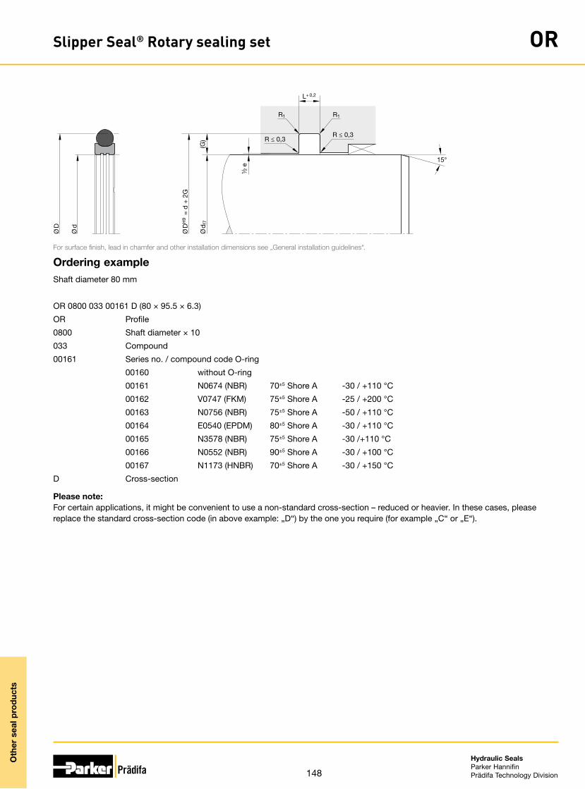
148
Hydraulic SealsParker HannifinPrädifa Technology Division
Oth
er s
eal p
rod
ucts
Slipper Seal® Rotary sealing set OR
Ø D
H9 =
d +
2G
(G)
½ e
15°
Ø d
f7
L+ 0,2
R1
R ≤ 0,3
R1
R ≤ 0,3
Ø D
Ø d
For surface finish, lead in chamfer and other installation dimensions see „General installation guidelines“.
Ordering exampleShaft diameter 80 mm
OR 0800 033 00161 D (80 × 95.5 × 6.3)
OR Profile
0800 Shaft diameter × 10
033 Compound
00161 Series no. / compound code O-ring
00160 without O-ring
00161 N0674 (NBR) 70±5 Shore A -30 / +110 °C
00162 V0747 (FKM) 75±5 Shore A -25 / +200 °C
00163 N0756 (NBR) 75±5 Shore A -50 / +110 °C
00164 E0540 (EPDM) 80±5 Shore A -30 / +110 °C
00165 N3578 (NBR) 75±5 Shore A -30 /+110 °C
00166 N0552 (NBR) 90±5 Shore A -30 / +100 °C
00167 N1173 (HNBR) 70±5 Shore A -30 / +150 °C
D Cross-section
Please note: For certain applications, it might be convenient to use a non-standard cross-section – reduced or heavier. In these cases, please replace the standard cross-section code (in above example: „D“) by the one you require (for example „C“ or „E“).

149
Hydraulic SealsParker HannifinPrädifa Technology Division
Oth
er s
eal p
rod
ucts
Slipper Seal® Rotary sealing set OR
Ø D
H9 =
d +
2G
(G)
½ e
15°
Ø d
f7
L+ 0,2
R1
R ≤ 0,3
R1
R ≤ 0,3
Ø D
Ø d
For surface finish, lead in chamfer and other installation dimensions see „General installation guidelines“.
Further sizes on request.
Standard rangeSize Groove O-ring
Ø d Ø D L No. CS ID
(mm) (mm) (mm) (mm) (mm)
0040 4 8.90 2.20 2-010 1.78 6.07
0060 6 10.90 2.20 2-011 1.78 7.65
0080 8 12.90 2.20 2-012 1.78 9.25
0100 10 14.90 2.20 2-013 1.78 10.82
0120 12 16.90 2.20 2-015 1.78 14.00
0140 14 18.90 2.20 2-016 1.78 15.60
0160 16 20.90 2.20 2-017 1.78 17.17
0170 17 21.90 2.20 2-018 1.78 18.77
0180 18 22.90 2.20 2-019 1.78 20.35
0190 19 26.50 3.20 2-118 2.62 21.89
0200 20 27.50 3.20 2-119 2.62 23.47
0220 22 29.50 3.20 2-120 2.62 25.07
0240 24 31.50 3.20 2-121 2.62 26.64
0250 25 32.50 3.20 2-122 2.62 28.24
0270 27 34.50 3.20 2-123 2.62 29.82
0280 28 35.50 3.20 2-124 2.62 31.41
0300 30 37.50 3.20 2-125 2.62 32.99
0320 32 39.50 3.20 2-126 2.62 34.59
0330 33 40.50 3.20 2-127 2.62 36.17
0350 35 42.50 3.20 2-128 2.62 37.77
0360 36 43.50 3.20 2-129 2.62 39.34
0370 37 44.50 3.20 2-130 2.62 40.94
0380 38 49 4.20 2-223 3.53 40.87
0400 40 51 4.20 2-224 3.53 44.04
0420 42 53 4.20 2-225 3.53 47.22
0450 45 56 4.20 2-226 3.53 50.39
0480 48 59 4.20 2-227 3.53 53.57
0500 50 61 4.20 2-228 3.53 56.74
0550 55 66 4.20 2-229 3.53 59.92
0600 60 71 4.20 2-230 3.53 63.09
Size Groove O-ring
Ø d Ø D L No. CS ID
(mm) (mm) (mm) (mm) (mm)
0630 63 74 4.20 2-231 3.53 66.27
0650 65 76 4.20 2-232 3.53 69.44
0700 70 81 4.20 2-233 3.53 72.62
0750 75 86 4.20 2-235 3.53 78.97
0800 80 91 4.20 2-237 3.53 85.32
0850 85 96 4.20 2-238 3.53 88.49
0900 90 101 4.20 2-240 3.53 94.84
0950 95 106 4.20 2-242 3.53 101.19
1000 100 111 4.20 2-243 3.53 104.37
1100 110 121 4.20 2-246 3.53 113.89
1200 120 131 4.20 2-249 3.53 123.42
1300 130 141 4.20 2-252 3.53 132.94
1400 140 151 4.20 2-255 3.53 142.47
1500 150 161 4.20 2-258 3.53 151.99
1600 160 171 4.20 2-260 3.53 164.69
1700 170 181 4.20 2-261 3.53 171.04
1800 180 191 4.20 2-263 3.53 183.74
1900 190 201 4.20 2-264 3.53 190.09
2000 200 215.50 6.30 2-369 5.33 202.57
2100 210 225.50 6.30 2-371 5.33 215.27
2200 220 235.50 6.30 2-372 5.33 221.62
2300 230 245.50 6.30 2-374 5.33 234.32
2400 240 255.50 6.30 2-375 5.33 240.67
2500 250 265.50 6.30 2-377 5.33 253.37
2560 256 277 8.10 2-449 6.99 253.37
2600 260 281 8.10 2-450 6.99 266.07
2700 270 291 8.10 2-451 6.99 278.77
2800 280 301 8.10 2-451 6.99 278.77
2900 290 311 8.10 2-452 6.99 291.47
3000 300 321 8.10 2-453 6.99 304.17

150
Hydraulic SealsParker HannifinPrädifa Technology Division
Oth
er s
eal p
rod
ucts
Slipper Seal® Rotary sealing set OR
Ø D
H9 =
d +
2G
(G)
½ e
15°
Ø d
f7
L+ 0,2
R1
R ≤ 0,3
R1
R ≤ 0,3
Ø D
Ø d
For surface finish, lead in chamfer and other installation dimensions see „General installation guidelines“.
Further sizes on request.
Size Groove O-ring
Ø d Ø D L No. CS ID
(mm) (mm) (mm) (mm) (mm)
3100 310 331 8.10 2-454 6.99 316.87
3200 320 241 8.10 2-455 6.99 329.57
3300 330 351 8.10 2-456 6.99 342.27
3400 340 361 8.10 2-457 6.99 354.97
3500 350 371 8.10 2-457 6.99 354.97
3600 360 281 8.10 2-458 6.99 367.67
3700 370 391 8.10 2-459 6.99 380.37
3800 380 401 8.10 2-460 6.99 393.07
3900 390 411 8.10 2-461 6.99 405.26
4000 400 421 8.10 2-461 6.99 405.26
4200 420 431 8.10 2-462 6.99 430.66
4500 450 471 8.10 2-465 6.99 456.06
4700 470 491 8.10 2-467 6.99 481.46
5000 500 521 8.10 2-469 6.99 506.86
5300 530 551 8.10 2-470 6.99 532.26
5500 550 571 8.10 2-471 6.99 557.66
5800 580 601 8.10 2-472 6.99 582.68
6000 600 621 8.10 2-473 6.99 608.08
6200 620 641 8.10 2-473 6.99 608.08
6400 640 661 8.10 2-474 6.99 633.48
6500 650 678 9.50 - 8.40 649
8000 800 828 9.50 - 8.40 810

151
Hydraulic SealsParker HannifinPrädifa Technology Division
Oth
er s
eal p
rod
ucts
Rotary sealing set RS
The profile RS rotary sealing set consists of a high-strength thermoplastic slide ring with particularly stable thermic properties and an elastomer expander ring.
The special contact surface geometry at the inner diameter of the slide ring with the patented (EP 0 643 243 B2) altering pitch has a major benefical effect on the lubrica-tion of the seal. This impacts positively on both friction resistance and wear.
The expander ring responsible for the static sealing function has a rectangular cross-section. Compared to O-rings, this has advantages with regard to contact load (seal-ing) and deformation behavior (pumping inside the groove).
The dynamic interior sealing method is preferable. We do not recommend a dynamic exterior sealing arrangement.
The slide ring compound used and its geometry allow use of the seal even under maximum permissible pressure (and in case of pressure peaks) without requiring ad-ditional anti-extrusion rings. At the same time, it is possible to take maximum advan-tage of the diameter play between rotor and stator without any functional impairment.
In principle, the seal can also be used as a final exterior sealing device. In case of doubt, however, we recommend the use of our profiles C5 or C9.
• Enhanced sealing performance in non-pressurized conditions.
• Robust seal profile for harshest operat-ing conditions.
• Extreme wear resistance.• Long service life thanks to application-
optimized compounds.• Insensitive to pressure peaks.• Improved lubrication due to pressure
medium deposit in the dynamic contact area.
• Extremely high extrusion resistance.• Installation in closed and undercut
housings.
Range of applicationPrimarily for alternating sealing of rotary applications in rotating tracks, pivot drives, hose reels, and in machine tool hydraulics.
Operating pressure ≤ 500 bar
Operating temperature -35 °C to +100 °C
Sliding speed ≤ 0.5 m/s
Recommendation for rotary transmissions:P × v ≤ 40 for L = 4.1 to 4.2P × v ≤ 70 for L = 6.0 to 6.3(For definition see catalogue „Hydraulic Seals“, chapter „Rotary Seals“, introduc-tion.)
CompoundsThe standard compound for the slide ring is a thermoplastic compound (W5071) with outstanding physical properties.The expander ring consists of our tried and proven standard NBR compound N3571 with 70 Shore A. For higher temperatures, we recommend HNBR compounds.
InstallationThe axial fit of the seal is especially narrow and suitable for grooves conforming to DIN ISO 7425. This benefits the total installation length of the rotary transmissions. By selecting suitable compounds, snap installation depending on profile width down to rotor diameter of app. 30 mm is possible. Below that, we recommend axially open grooves for installation.
In case of special operating conditions (specific pressure loads, temperature, speed, use in water, HFA, HFB fluids etc.), please contact our consultancy service for a selection of the material and design best suit-ing your particular application requirements.

152
Hydraulic SealsParker HannifinPrädifa Technology Division
Oth
er s
eal p
rod
ucts
Rotary sealing set RS
Ø d
1+0,
1
L+ 0,2
15°
R ≤ 0,5
R ≤ 0,5
R ≤ 0,5
R ≤ 0,5
Ø D
H9
Ø d
f7
Ø D
Ø d
For surface finish, lead in chamfer and other installation dimensions see „General installation guidelines“.
Further sizes on request.
d, D, L, Order code25 32.5 3.2 RS 0025 0071645 51.6 4.1 RS 0045 0071650 61 4.1 RS 0050 0071655 61.6 4.1 RS 0055 0071660 71 4.1 RS 0060 0071680 91 4.1 RS 0080 0071695 110.5 6.3 RS 0095 00716
100 111 4.1 RS 0100 00716105 120.4 6.2 RS 0105 00716110 121 4.2 RS 0110 00716124 139.2 6.1 RS 0124 00716125 135.4 5.1 RS 0125 00716130 140 6 RS 0130 00715145 160 6.2 RS 0145 00716160 171.7 5.7 RS 0160 00716170 185.2 6.2 RS 0170 00716250 265.5 6.3 RS 0250 00716

153
Hydraulic SealsParker HannifinPrädifa Technology Division
Oth
er s
eal p
rod
ucts
Sealing set for piston accumulators KS
The Ultrathan® sealing set profile KS has been developed especially for sealing pis-tons in dual media hydraulic accumulators. It consits of two u-rings of different design and compound. The shape of the seals makes them ideal for the permanent separa-tion of the pressurized media e.g. oil and gas with low friction forces.
The KS can be used in other applications including industrial shock absorbers, hydro-pneumatic equipment such as feed and counter balance units, hydro-pneumatic booster or converter units, pressure transducers and operating cylinders.
• Robust seal profile for harshest operat-ing conditions.
• Extreme wear resistance.• Assembly on one-part piston is pos-
sible.• High extrusion resistance.• Excellent media resistance in case of
suitable compound selection.• Suitable compounds available for
special requirements of the chemical process industry.
• Suitable compounds available for spe-cial requirements of the food processing industry.
• Dimensions according to ISO 5597.• Installation in closed and undercut
housings.• Additional sizes of machined products
available on short notice.
Range of applicationOperating pressure ≤ 350 bar
Operating temperature -30 °C to +80 °C
Sliding speed ≤ 3 m/s
Media Hydraulic oils based on mineral oil and gases
CompoundsParker polyurethane Ultrathan® P5008 is used for the oil side seal and polyurethane Ultrathan® P5010 is used for the gas side. When compared to commercial polyure-thanes both these compounds have a superior resistance to high temperature and lower compression set values.
InstallationThe performance of profile KS piston seal set is only guaranteed when the green colour seal (KH ... P5008) is installed on the oil side of the piston and the red colour seal (KG ... P5010) on the gas side. The general recommendations as shown in our hydraulics brochure are applicable to the housing groove and seal installation, e. g. no sharp edges, no sharp tools, clean components, etc.
In case of special operating conditions (specific pressure loads, temperature, speed, use in water, HFA, HFB fluids etc.), please contact our consultancy service for a selection of the material and design best suit-ing your particular application requirements.

154
Hydraulic SealsParker HannifinPrädifa Technology Division
Oth
er s
eal p
rod
ucts
Sealing set for piston accumulators KS
R ≤ 0,2
R ≤
0,2
R ≤ 0,3
R ≤ 0,3
R ≤
0,3
R ≤ 0,2
R ≤
0,2
R ≤
0,3
Ø d
Ø D
Ø D
H9
Ø d
Ø D
Ø d
h9
L+ 0,25 L+ 0,25
H
H
For surface finish, lead in chamfer and other installation dimensions see „General installation guidelines“.
1) ISO 5597Further sizes on request.
D, d, H, L, ISO1) Order code32 24 5.7 6.3 KS 0032 0071035 27 5.7 6.3 KS 0035 0071040 32 5.7 6.3 • KS 0040 0071050 40 7.3 8 • KS 0050 0071063 53 7.3 8 • KS 0063 0071080 65 11.4 12.5 • KS 0080 0071085.73 70.73 11.4 12.5 KS 0086 00710
100 85 11.4 12.5 • KS 0100 00710125 105 14.5 16 • KS 0125 00710160 140 14.5 16 • KS 0160 00714180 160 14.5 16 KS 0180 00710


PTD 3350 EN · 02/2016© 2016 Parker Hannifin Corporation · Subject to change.
Parker-Prädifa Worldwide
Europe, Middle East, AfricaAE – United Arab Emirates, Dubai Tel: +971 4 8127100 [email protected]
AT – Austria, Wiener Neustadt Tel: +43 (0)2622 23501-0 [email protected]
AT – Eastern Europe, Wiener Neustadt Tel: +43 (0)2622 23501 900 [email protected]
AZ – Azerbaijan, Baku Tel: +994 50 2233 458 [email protected]
BE/LU – Belgium, Nivelles Tel: +32 (0)67 280 900 [email protected]
BG – Bulgaria, Sofia Tel: +359 2 980 1344 [email protected]
BY – Belarus, Minsk Tel: +48 (0)22 573 24 00 [email protected]
CH – Switzerland, Etoy Tel: +41 (0)21 821 87 00 [email protected]
CZ – Czech Republic, Klecany Tel: +420 284 083 111 [email protected]
DE – Germany, Kaarst Tel: +49 (0)2131 4016 0 [email protected]
DK – Denmark, Ballerup Tel: +45 43 56 04 00 [email protected]
ES – Spain, Madrid Tel: +34 902 330 001 [email protected]
FI – Finland, Vantaa Tel: +358 (0)20 753 2500 [email protected]
FR – France, Contamine s/Arve Tel: +33 (0)4 50 25 80 25 [email protected]
GR – Greece, Athens Tel: +30 210 933 6450 [email protected]
HU – Hungary, Budaörs Tel: +36 23 885 470 [email protected]
IE – Ireland, Dublin Tel: +353 (0)1 466 6370 [email protected]
IT – Italy, Corsico (MI) Tel: +39 02 45 19 21 [email protected]
KZ – Kazakhstan, Almaty Tel: +7 7273 561 000 [email protected]
NL – The Netherlands, Oldenzaal Tel: +31 (0)541 585 000 [email protected]
NO – Norway, Asker Tel: +47 66 75 34 00 [email protected]
PL – Poland, Warsaw Tel: +48 (0)22 573 24 00 [email protected]
RO – Romania, Bucharest Tel: +40 21 252 1382 [email protected]
RU – Russia, Moscow Tel: +7 495 645-2156 [email protected]
SE – Sweden, Spånga Tel: +46 (0)8 59 79 50 00 [email protected]
SK – Slovakia, Banská Bystrica Tel: +421 484 162 252 [email protected]
SL – Slovenia, Novo Mesto Tel: +386 7 337 6650 [email protected]
TR – Turkey, Istanbul Tel: +90 216 4997081 [email protected]
UA – Ukraine, Kiev Tel: +48 (0)22 573 24 00 [email protected]
UK – United Kingdom, Warwick Tel: +44 (0)1926 317 878 [email protected]
ZA – South Africa, Kempton Park Tel: +27 (0)11 961 0700 [email protected]
North AmericaCA – Canada, Milton, Ontario Tel: +1 905 693 3000
US – USA, Cleveland Tel: +1 216 896 3000
Asia PacificAU – Australia, Castle Hill Tel: +61 (0)2-9634 7777
CN – China, Shanghai Tel: +86 21 2899 5000
HK – Hong Kong Tel: +852 2428 8008
IN – India, Mumbai Tel: +91 22 6513 7081-85
JP – Japan, Tokyo Tel: +81 (0)3 6408 3901
KR – South Korea, Seoul Tel: +82 2 559 0400
MY – Malaysia, Shah Alam Tel: +60 3 7849 0800
NZ – New Zealand, Mt Wellington Tel: +64 9 574 1744
SG – Singapore Tel: +65 6887 6300
TH – Thailand, Bangkok Tel: +662 186 7000
TW – Taiwan, Taipei Tel: +886 2 2298 8987
South AmericaAR – Argentina, Buenos Aires Tel: +54 3327 44 4129
BR – Brazil, Sao Jose dos Campos Tel: +55 800 727 5374
CL – Chile, Santiago Tel: +56 2 623 1216
MX – Mexico, Toluca Tel: +52 72 2275 4200
Parker Hannifin GmbHEngineered Materials Group EuropeP.O. Box 164174306 Bietigheim-Bissingen ∙ GermanyTel. +49 7142 351-0 ∙ Fax +49 7142 351-293www.parker.com/praedifae-mail: [email protected]