HYDRAULIC SEALING ELEMENTS
14
HYDRAULIC SEALING ELEMENTS
Transcript of HYDRAULIC SEALING ELEMENTS

TOLERANCES FOR ELASTOMERS
16
NOMINAL DIMENSION CLASS M1 CLASS M2 CLASS M3 CLASS M4
F
C F
C
F
C
F
C
≤ 6.3 ±0.10 ±0.10 ±0.15 ±0.20 ±0.25 ±0.40 ±0.50 ±0.506.3< ≤10 ±0.10 ±0.15 ±0.20 ±0.20 ±0.30 ±0.50 ±0.70 ±0.7010< ≤16 ±0.15 ±0.20 ±0.20 ±0.25 ±0.40 ±0.60 ±0.80 ±0.8016< ≤25 ±0.20 ±0.20 ±0.25 ±0.35 ±0.50 ±0.80 ±1.00 ±1.0025< ≤40 ±0.20 ±0.25 ±0.35 ±0.40 ±0.60 ±1.00 ±1.30 ±1.3040< ≤63 ±0.25 ±0.35 ±0.40 ±0.50 ±0.80 ±1.30 ±1.60 ±1.6063< ≤100 ±0.35 ±0.40 ±0.50 ±0.70 ±1.00 ±1.60 ±2.00 ±2.00100< ≤160 ±0.40 ±0.50 ±0.70 ±0.80 ±1.30 ±2.00 ±2.50 ±2.50
Extract from DIN 7168.
NOMINAL DIMENSION
TOLERANCES ACCORDING TO DIN 7168 “MEDIUM”
RESTRICTED WORKING TOLERANCES
≤ 6
6< ≤30
30< ≤65
65< ≤120
120< ≤200
±0.1 ±0.2 ±0.3 ±0.3 ±0.5
0.100.150.200.300.40
Permissible deviations of dimensions in mm.
160< 0.30 0.50 0.80 1.50 1.50
Permissible deviations in %.
Extract from ISO 3302-1.
TOLERANCES FOR MACHINED PARTS OF THERMOPLASTICS
HYDRAULIC SEALING ELEMENTS

Hydraulic cylinders are being used in mechanical applications where reciprocating forces and movements are needed. Sealing element is one of the most important parts of the cylinders. The sealing elements are being installed into the respective groove with a preload. Figure 1 shows the sealing element in free state, preload after the assembly of the seal and the free space needed in the housing.
The sealing element is able to work in low pressures due to this preload. Figure 2 shows the pressurized media filling into the groove and sealing element is expanded with this pressure. Sealing elements are produced from such materials that can change their form when force is applied (Figure 2) and can return to the original form when this force disappears (Figure 1). In this respect sealing elements are produced from elastomers, thermoplastics or thermoplastic elastomers.
PRESSURE
The first important feature that should be looked at in the system is the pressure, because the system working force is obtained by the cylinder bore diameter and the system pressure. While calculating the system pressure we recommend to take the shock pressures into consideration which are generally higher than the normal operating pressures. Nowadays the demand for higher forces made the system pressures increase in the hydraulic systems. That is why there are new profiles with new engineering materials in the sealing elements. Kastaş offers sealing solutions that can go up to 700 bar. Operating pressure of the sealing elements can be seen in Product Programme.
HYDRAULIC SEALING ELEMENTS
18
WORKING PRINCIPLE OF SEALING ELEMENTS
System pressure, sliding speed, temperature, media, surface roughness and system tolerances are the important parameters when choosing the type of the sealing element.
CHOOSING SEALING ELEMENTS
Figure 1Sealing element in free state
Figure 2Sealing element under pressure
The media and the working temperature are two most important factors in choosing the material for sealing elements. The ideal working temperature for sealing element and system is 50°C, but the application temperature usually goes up to 100°C. In dynamic applications, sealing elements do have direct contact with the sliding surface and that is why they have been effected by the heat originated from the friction forces. The system temperature should be less than the working temperature of the sealing element. Table 1 shows the maximum operating temperatures of the sealing elements. For special applications that require high temperatures, we recommend sealing elements produced from FKM and/or PTFE material. For low temperatures, it is believed that the sealing elements become harder (glass transition) and will not do the required job, but actually depending on the media the sealing elements are able to work without any problems up to -40°C. The operating temperatures for the sealing elements can be seen in Product’s Programme.
TEMPERATURE
19
The minimum and maximum operating temperature of the sealing elements do change with the media they are being used in. Sealing elements can be used in mineral oils (DIN 51524), non flammable hydraulic oils (VDMA 24317 or DIN 24320), atmosphere, water and different type of media (See section; Chemical Resistance of Rubber Materials). Table 1 shows the most common media used with the sealing elements.
The viscosity of the media is one of the reasons of wear in the sealing elements. Pressure and temperature change the viscosity of the media. The viscosity of the media increases with the pressure. Increasing temperature reduces the viscosity of the media (this change depends on the media type). The effect of operating pressure and temperature on the viscosity should be investigated when choosing the media type.
MEDIA
Material WaterAirOperating Temp.Non-Flammable Hydraulic Oils
Mineral Oils
HFA HFB HFC HFD
80 NBR -30 55 60 60 - 105 105 90
70 NBR -35 55 60 60 - 105 105 90
90 NBR -30 55 60 60 - 105 105 90
90 FKM -25 55 60 60 150 225 200 80
70 FKM -30 55 60 60 150 225 200 80
80 PU -30 40 40 40 - 80 80 40
92 PU -30 40 40 40 - 100 80 40
POM -40 55 60 60 80 125 100 90
PTFE -80 - - - 150 200 200 150
Polyester Elastomer -30 40 40 40 - 100 80 40
Figure 3Friction force vs Sliding Speed
MIXEDFRICTION
STATIC FRICTION
FLUIDFRICTION
SPEED
FRIC
TIO
N F
ORC
E
SPEED
The speed of the cylinder can go up to 15 m/sec depending on the material of the sealing element, design and the application. Speed is one of the important features which defines the oil film generation and the friction forces. Figure 3 shows increasing of the friction forces with speed increasing and oil film thickness decreasing. That is why at high sliding speeds the sealing elements should be chosen from PTFE material. The sliding speed for the sealing elements can be seen in our Product Programme.
OPERATING TEMPERATURE OF THE MATERIALS USED FOR SEALING ELEMENTS
STANDARD KASTAŞ COMPOUNDS
Table 1Operating temperature of the materials used for sealing elements

20
The surfaces that the sealing elements will be working should be honed, grinded and polished. Surface roughness should be according to the catalogue information of the respective sealing element. Figure 4 shows the schematic of sealing element material matching with the surface roughness values. As it is seen in Figure 4, rubber materials can adopt with the irregularities of the surface; on the other hand PTFE material adaptation is not as good as the other sealing materials.
SURFACE ROUGHNESS
Figure 4 Sealing edge in contact with counter surface
Ra value that we indicate in our catologue is the arithmetic average of the absoloute roughness values in specific length of surface (Figure 5).
METAL
NBR
METAL
METAL
PTFE
PU
Figure 5 Calculation of Ra surface roughness value
L
SURFACE AXIS
t
Ra
Ra= 1Lt
0
Lt
5
Rz 5
Rz1+Rz2+Rz3+Rz4+Rz5
5Rz=
Rz value that we indicate in our catologue is the average of the 5 consecutive maximumum roughness values in specific length of surface, Rmax is the maximum of these values (Figure 6).
Figure 6 Rz surface roughness value and calculation of Rmax
3 4
t
1
max
L L L L L
L
R
Rz 1Rz 2 Rz 3
Rz 4
2
As it can be seen from the above graphs, similar values of Rmax at depth C, we see that Rmr value varies between 35% and 90%. The surface roughness on last graph shown on the left side gives an example of the ideal surface. It is also seen that we do not want to have Rmr value to be 100%. If the Rmr value is higher than 90%, the sliding surface behaves like a mirror and do not leave any oil film on the surface. This basically makes the sealing element to be damaged in shorter period of time.
21
Figure 8Surface roughness samples
0 20 40 60 80 100 %
Figure 7 Calculation of Rmr surface roughness ratio
Rmr= x1+x2+x3+x4+x5+x6
LT
x100
xxL
C=
x xx x1 2 43 5 6
T
Rz2
During the working of the sealing element average surface contact area does have an important role besides the Ra and Rz values. Surface contact area Rmr is the ratio of surface roughness cutted with C depth and the proportion of the contact surface areas to non contact surface areas in the specific surface length. Kastaş supplies Rmr values in the catalogue in order to maximize the performance of the sealing elements according to C=Rz/2 (Figure 7).
22
System tolerances are the important factors on the life span ofthe sealing elements. Inappropriate dimensions, tolerances and decentered hydraulic cylinders make the sealing elements wear out in short period of time and the system do not give the required performance.
All the dimensions and tolerances are indicated on the product pages of our catalogue. Table 2 shows the general tolerances used in the hydraulic systems. The cylinder bore in hydraulic system is produced from ST 52 or better quality.
Sliding surfaces should have the mentioned operations (honed, grinded, etc) in order to obtain the required surface roughness values. Rods should be produced from steel (chrome plated, grinded and polished). Other cylinder parts should be from steel, steel casting, cast iron or special engineering plastics.
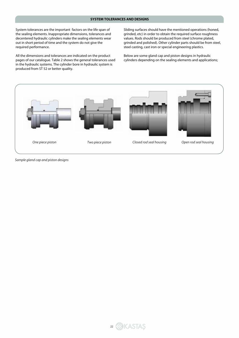
Below are some gland cap and piston designs in hydraulic cylinders depending on the sealing elements and applications;
SYSTEM TOLERANCES AND DESIGNS
One piece piston Two piece piston Closed rod seal housing Open rod seal housing
Sample gland cap and piston designs

22
System tolerances are the important factors on the life span ofthe sealing elements. Inappropriate dimensions, tolerances and decentered hydraulic cylinders make the sealing elements wear out in short period of time and the system do not give the required performance.
All the dimensions and tolerances are indicated on the product pages of our catalogue. Table 2 shows the general tolerances used in the hydraulic systems. The cylinder bore in hydraulic system is produced from ST 52 or better quality.
Sliding surfaces should have the mentioned operations (honed, grinded, etc) in order to obtain the required surface roughness values. Rods should be produced from steel (chrome plated, grinded and polished). Other cylinder parts should be from steel, steel casting, cast iron or special engineering plastics.
Below are some gland cap and piston designs in hydraulic cylinders depending on the sealing elements and applications;
SYSTEM TOLERANCES AND DESIGNS
One piece piston Two piece piston Closed rod seal housing Open rod seal housing
Sample gland cap and piston designs
23
TOLE
RAN
CES
IN H
YDRA
ULI
C CY
LIN
DER
S
>
<=
H8
H9
H10
H
11
H12
e9
f7
f8
f9
h8
h9
h1
0 h1
1
3 +1
4 +2
5 +4
0 +6
0 +1
00
-14
-6
-6
-6
0 0
0 0
-0
-0
-0
-0
-0
-3
9 -1
6 -2
0 -3
1 -1
4 -2
5 -4
0 -6
0
3
6 +1
8 +3
0 +4
8 +7
5 +1
20
-20
-10
-10
-10
0 0
0 0
-0
-0
-0
-0
-0
-5
0 -2
2 -2
8 -4
0 -1
8 -3
0 -4
8 -7
5
6
10
+22
+36
+58
+90
+150
-2
5 -1
3 -1
3 -1
3 0
0 0
0
-0
-0
-0
-0
-0
-6
1 -2
8 -3
5 -4
9 -2
2 -3
6 -5
8 -9
0
10
18
+2
7 +4
3 +7
0 +1
10
+180
-3
2 -1
6 -1
6 -1
6 0
0 0
0
-0
-0
-0
-0
-0
-7
5 -3
4 -4
3 -5
9 -2
7 -4
3 -7
0 -1
10
18
30
+3
3 +5
2 +8
4 +1
30
+210
-4
0 -2
0 -2
0 -2
0 0
0 0
0
-0
-0
-0
-0
-0
-9
2 -4
1 -5
3 -7
2 -3
3 -5
2 -8
4 -1
30
30
50
+3
9 +6
2 +1
00
+160
+2
50
-50
-25
-25
-25
0 0
0 0
-0
-0
-0
-0
-0
-1
12
-50
-64
-87
-39
-62
-100
-1
60
50
80
+4
6 +7
4 +1
20
+190
+3
00
-60
-30
-30
-30
0 0
0 0
-0
-0
-0
-0
-0
-1
34
-60
-76
-104
-4
6 -7
4 -1
20
-190
80
12
0 +5
4 +8
7 +1
40
+220
+3
50
-72
-36
-36
-36
0 0
0 0
-0
-0
-0
-0
-0
-1
59
-71
-90
-123
-5
4 -8
7 -1
40
-220
12
0 18
0 +6
3 +1
00
+160
+2
50
+400
-8
5 -4
3 -4
3 -4
3 0
0 0
0
-0
-0
-0
-0
-0
-1
85
-83
-106
-1
43
-63
-100
-1
60
-250
18
0 25
0 +7
2 +1
15
+185
+2
90
+460
-1
00
-50
-50
-50
0 0
0 0
-0
-0
-0
-0
-0
-2
15
-96
-122
-1
65
-72
-115
-1
85
-290
25
0 31
5 +8
1 +1
30
+210
+3
20
+520
-1
10
-56
-56
-56
0 0
0 0
-0
-0
-0
-0
-0
-2
40
-108
-1
37
-185
-8
1 -1
30
-210
-3
20
31
5 40
0 +8
9 +1
40
+230
+3
60
+570
-1
25
-62
-62
-62
0 0
0 0
-0
-0
-0
-0
-0
-2
65
-119
-1
51
-202
-8
9 -1
40
-230
-3
60
40
0 50
0 +9
7 +1
55
+250
+4
00
+630
-1
35
-68
-68
-68
0 0
0 0
-0
-0
-0
-0
-0
-2
90
-131
-1
65
-223
-9
7 -1
55
-250
-4
00
NO
MIN
AL
DIM
ENSI
ON
(mm
)
HO
LE T
OLE
RAN
CES
(µm
)RO
D T
OLE
RAN
CES
(µm
)
Tabl
e 2
Tole
ranc
es in
hyd
raul
ic c
ylin
ders
Extr
act f
rom
ISO
286
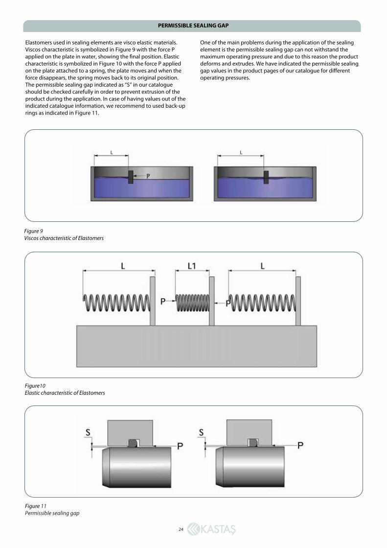
Elastomers used in sealing elements are visco elastic materials. Viscos characteristic is symbolized in Figure 9 with the force P applied on the plate in water, showing the final position. Elastic characteristic is symbolized in Figure 10 with the force P applied on the plate attached to a spring, the plate moves and when the force disappears, the spring moves back to its original position. The permissible sealing gap indicated as “S” in our catalogue should be checked carefully in order to prevent extrusion of the product during the application. In case of having values out of the indicated catalogue information, we recommend to used back-up rings as indicated in Figure 11.
One of the main problems during the application of the sealing element is the permissible sealing gap can not withstand the maximum operating pressure and due to this reason the product deforms and extrudes. We have indicated the permissible sealing gap values in the product pages of our catalogue for different operating pressures.
PERMISSIBLE SEALING GAP
24
Figure 9Viscos characteristic of Elastomers
Figure10Elastic characteristic of Elastomers
Figure 11Permissible sealing gap
L L
Before installation; we highly recommend to see section; General Installation Information of Technical Catalogue. Heating the seals before installation to +70°C hot oil will make the seal material more elastic and it will be easier to install the seal. It is very important not to create any condition to damage the material of the sealing element during this process.
Hydraulic sealing elements can be installed to the open and closed grooves by hand. We recommend special assembly tools for the installation of the sealing elements in especially closed grooves. These assembly tools will speed up the installation and prevent the damaging of the sealing element. Different assembly tool samples can be seen in Figure 12.
INSTALLATION
25
Figure 12Sample assembly tools for closed rod seal housing
After the installation of the rod seals, in order not to have damage on the sealing elements while pushing the rod though the gland cap special assembly tool shown in Figure 13 should be used in order the protect the seals while the rod is inserted to the gland cap. All the assembly tools should not have any sharp edges and the surface roughness should be less than Rt ≤ 4µm.
Figure 13Assembly device after seal is installed

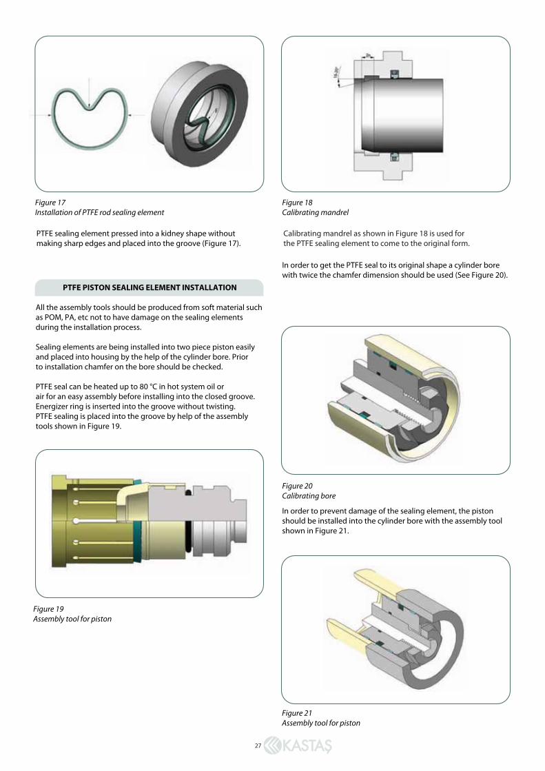
In order to get the PTFE seal to its original shape a cylinder bore with twice the chamfer dimension should be used (See Figure 20).
In order to prevent damage of the sealing element, the piston should be installed into the cylinder bore with the assembly tool shown in Figure 21.
27
PTFE sealing element pressed into a kidney shape without making sharp edges and placed into the groove (Figure 17).
Figure 17Installation of PTFE rod sealing element
Calibrating mandrel as shown in Figure 18 is used for the PTFE sealing element to come to the original form.
Figure 18Calibrating mandrel
Figure 20Calibrating bore
Figure 21Assembly tool for piston
Figure 19Assembly tool for piston
PTFE PISTON SEALING ELEMENT INSTALLATION
All the assembly tools should be produced from soft material such as POM, PA, etc not to have damage on the sealing elements during the installation process.
Sealing elements are being installed into two piece piston easily and placed into housing by the help of the cylinder bore. Prior to installation chamfer on the bore should be checked.
PTFE seal can be heated up to 80 °C in hot system oil or air for an easy assembly before installing into the closed groove. Energizer ring is inserted into the groove without twisting. PTFE sealing is placed into the groove by help of the assembly tools shown in Figure 19.

28
SAMPLE DESIGNS
Light duty sample design-1
Light duty sample design-2
Light duty sample design-3
K06 K22 KBTKO K15 K69KO
K05 K33 K68KO KOK18
K07 K36 K68KO KOK23 KKT

28
SAMPLE DESIGNS
Light duty sample design-1
Light duty sample design-2
Light duty sample design-3
K06 K22 KBTKO K15 K69KO
K05 K33 K68KO KOK18
K07 K36 K68KO KOK23 KKT
29
Medium duty sample design-4
Medium duty sample design-5
Medium duty sample design-6
K05 K32 K68KO KO+K81K18K29 K69
K703 K81+KO K81+KOKBTKBT K17K35

30
Heavy duty sample design-7
Heavy duty sample design-8
Heavy duty sample design-9
K27 K84 K83K73K73 K19K31 K29 KBTKBT
DRAINAGECHANNEL
K11 K34 K73 K84 KBT K73
K42
K83
K05 K01 K73 K84 KBT KBT K03 K73 K81+KO