Hydraulic Recovery Winch · Hydraulic Recovery Winch ... The winch should be mounted as closed to...
12
1
Transcript of Hydraulic Recovery Winch · Hydraulic Recovery Winch ... The winch should be mounted as closed to...
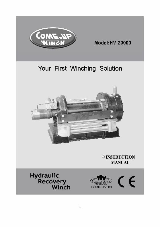
1
2
Hydraulic Recovery Winch
Thanks for purchasing a WINCH. This manual covers operation and maintenance of the winch. All information in this publication is based on the latest
production information available at the time of printing.
General Safety Precautions
A Winch is designed to give safe and dependable service if operated
according to the instructions. Read and understand this manual before installation and
operation of winch.
Follow these general safety precautions:
˙̇̇̇Don't use unsuitable snatch block or accessories.
˙̇̇̇Don't use unsuitable wire rope in construction , strength or having any defects.
˙̇̇̇Check the winch for smooth operation without load before winching operation.
˙̇̇̇Make sure the wire rope is wound evenly on the first layer on the drum, rewind it if not
evenly wound.
1. The winch is rated for intermittent-periodic duty.
2. The winch is not to be used to lift, support or otherwise transport personnel.
3. A minimum of five (5) wraps of rope around the drum are necessary to support the
rated load.
4. When choosing the right winch, you need to consider the vehicle size and weight.
As a general guide, you need a winch with a maximum load rating of at least one
and a half times greater than the gross vehicle weight.
5. The rated line pull of the winch must be powerful enough to overcome the added
resistance caused by whatever the vehicle is stuck in.
WARNING
3
I. Safety Precaution
Please read and understand this Instruction Manual before installing your winch.
Don’t use unsuitable wire rope in construction, strength or having any defects.
Don’t use unsuitable hook and snatch block for wire rope.
The operator of winch in some cases may be required to have
qualification according to applicable laws and ordinances.
Do not use winch as a lifting device or a hoist for vertical lifting
Do not use winch to move people.
Do not exceed maximum line pull ratings shown in tables.
Shock load must not exceed these ratings.
Keep hands clear of wire rope and fairlead opening.
Pull from a fleet angle below 15 degree to straighten up the vehicle
or load. The improper fleet angle could increase wear and tear
on the winch and the wire rope.
Use leather gloves or a heavy rag when handling the wire rope.
When winching a heavy load lay a heavy blanket or jacket
over the wire rope near the hook end.
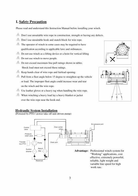
Reservoir
Suction
strainer
Return
filter
Pump
Control
Hydraulic System Installation
Pressurerelief valve
Over center
valvevalve
Winch
Transfer
box PTO
( Powered by a PTO / power take off unit driven pump)( Powered by a PTO / power take off unit driven pump)
Air pressure port
Drain port
Advantage: Professional winch system for
“Working” applications, cost
effective, extremely powerful,
reliable, light weight and
variable line speed for high
work rate.
Hydraulic System Installation (Powered by PTO / power take off unit driven pump)
4
As a general rule: � The hydraulic system shown above must contain over center valve, control valve and pressure
relief valve for having the winch operated correctly. Failure to use the correct valves may result in damage to the winch, property, or personal injury.
� The relief valve must be set at the winch operating pressure and doest not exceed the rated pressure. Failure to use the correct pressure and flow may result in damage to the winch, property or personal injury.
� The hydraulic pressure or flow lower than those ratings for the winch may result in a lower line pull or lower line speed.
� The bigger nominal bore hose, the better winch performance. ���� Keeping cleanliness and accuracy on the hydraulic system installation are essential to have
hydraulic system functioned properly ���� Pressure and flow loss is increased as hose length increases or hose size decreases. ���� Pressure and return lines in excess of 3.5 meter ( 11.5” ) should be compensated with an increase
in nominal hose size ����Setting range of 70~210 bar and pilot ratio of 4.1:1 for over center valve are recommended.
II. Performance Data ���� Specification
Model HV-20000
Line Pull kg / lb 9,090 / 20,000
Line Speed mpm / fpm 7.2 / 23.6
Operation pressure 172 bar / 2,500 psi
Max. oil flow 15.9 g / min ( 60 l / min)
Displacement 125 cm
3 / rev
7.6 in3 / rev Motor
Rotation Anti-clockwise
Type 2 stage planetary gear Gear
train Ratio 32:1
Freespool One way rotating ring gear
Brake Spring-applied,multi-disc brake integrated in motor
���� Line Pull and Speed Model HV-20000
Line pull kg / lb 9,090 / 20,000
Line speed mpm / fpm 7.2 / 23.6 1st
layer Rope cap m / ft 12.3 / 40.7
Line pull kg / lb 7,690 / 16,918
Line speed mpm / fpm 8.5 / 27.9 2nd
layer Rope cap m / ft 26.8 / 88.7
Line pull kg / lb 6,664 / 14,661
Line speed mpm / fpm 9.8 / 32.2 3rd
layer Rope cap m / ft 43.6 / 144.4
Line pull kg / lb 5,880 / 12,936
Line speed mpm / fpm 11.1 / 36.4 4th
layer Rope cap m / ft 62.6 / 207.4
Line pull kg / lb 5,260 / 11,572
Line speed mpm / fpm 12.4 / 40.7 5th
layer Rope cap m / ft 80 / 265
The performance listed is applicable only when using the recommended wire rope of
14 mm X 80 m ( 9/16” X 265’ ) 6 X W(19) + IWRC
5
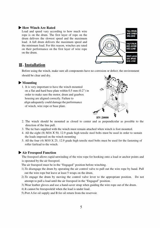
���� How Winch Are Rated Load and speed vary according to how much wire
rope is on the drum. The first layer of rope on the
drum delivers the slowest speed and the maximum
load. A full drum delivers the maximum speed and
the minimum load. For this reason, winches are rated
on their performance on the first layer of wire rope
on the drum.
.ⅢⅢⅢⅢ Installation
Before using the winch, make sure all components have no corrosion or defect; the environment
should be clear and dry.
���� Mounting
1. It is very important to have the winch mounted
on a flat and hard base plate within 0.5 mm (0.2”) in
order to make sure the motor, drum and gearbox
housing are aligned correctly. Failure to
ialigniadequately couldidamageitheiperformance
of winch, wire rope or base plate.
HV-20000
2. The winch should be mounted as closed to center and as perpendicular as possible to the
direction of the line pull.
3. The tie bars supplied with the winch must remain attached when winch is foot mounted.
4. All the eight (8) M16 X 50, 12.9 grade high tensile steel bolts must be used in order to sustain
the loads imposed on the winch mounting
5. All the four (4) M10 X 25, 12.9 grade high tensile steel bolts must be used for the fastening of
roller fairlead to the winch.
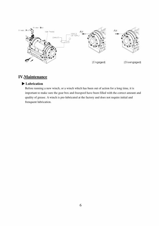
���� Air Freespool Function
The freespool allows rapid unwinding of the wire rope for hooking onto a load or anchor points and
is operated by the air freespool.
The air freespool must be in the “Engaged” position before winching.
1).To disengage the drum by operating the air control valve to pull out the wire rope by hand. Pull
out the wire rope but leave at least 5 wraps on the drum.
2).To engage the drum by moving the control valve lever to the appropriate position. Do not
attempt to pull a load until the air freespool in the “Engaged” position.
3).Wear leather gloves and use a hand-saver strap when guiding the wire rope out of the drum.
4).It cannot be freespooleld when the load is under load.
5).Port A for oil supply and B for oil return from the reservoir.
6
IV.Maintenance
���� Lubrication
Before running a new winch, or a winch which has been out of action for a long time, it is
important to make sure the gear box and freespool have been filled with the correct amount and
quality of grease. A winch is pre-lubricated at the factory and does not require initial and
frenquent lubrication.
7
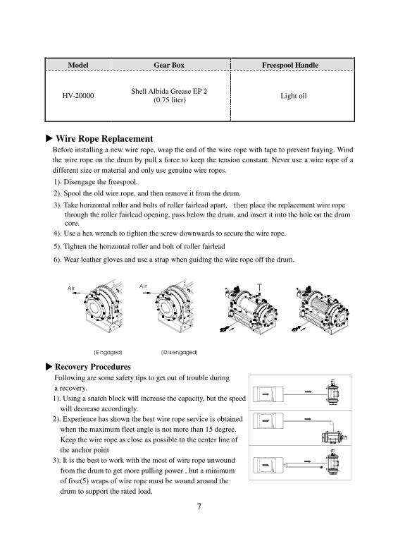
Model Gear Box Freespool Handle
HV-20000 Shell Albida Grease EP 2
(0.75 liter) Light oil
� Wire Rope Replacement Before installing a new wire rope, wrap the end of the wire rope with tape to prevent fraying. Wind
the wire rope on the drum by pull a force to keep the tension constant. Never use a wire rope of a
different size or material and only use genuine wire ropes.
1). Disengage the freespool.
2). Spool the old wire rope, and then remove it from the drum.
3). Take horizontal roller and bolts of roller fairlead apart, then place the replacement wire rope
through the roller fairlead opening, pass below the drum, and insert it into the hole on the drum
core.
4). Use a hex wrench to tighten the screw downwards to secure the wire rope.
5). Tighten the horizontal roller and bolt of roller fairlead
6). Wear leather gloves and use a strap when guiding the wire rope off the drum.
���� Recovery Procedures
Following are some safety tips to get out of trouble during
a recovery.
1). Using a snatch block will increase the capacity, but the speed
will decrease accordingly.
2). Experience has shown the best wire rope service is obtained
when the maximum fleet angle is not more than 15 degree.
Keep the wire rope as close as possible to the center line of
the anchor point
3). It is the best to work with the most of wire rope unwound
from the drum to get more pulling power , but a minimum
of five(5) wraps of wire rope must be wound around the drum to support the rated load.
8
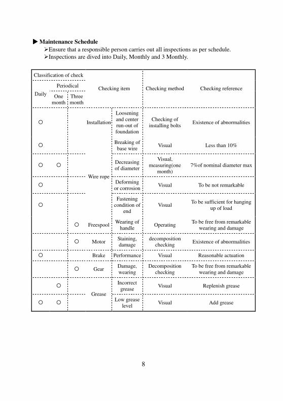
���� Maintenance Schedule
�Ensure that a responsible person carries out all inspections as per schedule.
�Inspections are dived into Daily, Monthly and 3 Monthly.
Classification of check
Periodical
Daily One
month
Three
month
Checking item Checking method Checking reference
� Installation
Loosening
and center
run-out of
foundation
Checking of
installing bolts Existence of abnormalities
� Breaking of
base wire Visual Less than 10%
� � Decreasing
of diameter
Visual,
measuring(one
month)
7%of nominal diameter max
� Deforming
or corrosion Visual To be not remarkable
�
Wire rope
Fastening
condition of
end
Visual To be sufficient for hanging
up of load
� Freespool Wearing of
handle Operating
To be free from remarkable
wearing and damage
� Motor Staining,
damage
decomposition
checking Existence of abnormalities
� Brake Performance Visual Reasonable actuation
� Gear Damage,
wearing
Decomposition
checking
To be free from remarkable
wearing and damage
� Incorrect
grease Visual Replenish grease
� �
Grease Low grease
level Visual Add grease
9
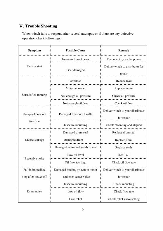
ⅤⅤⅤⅤ. Trouble Shooting
When winch fails to respond after several attempts, or if there are any defective
operation check followings:
Symptom Possible Cause Remedy
Disconnection of power Reconnect hydraulic power
Fails in start Gear damaged
Deliver winch to distributor for
repair
Overload Reduce load
Motor worn out Replace motor
Not enough oil pressure Check oil pressure
Unsatisfied running
Not enough oil flow Check oil flow
Damaged freespool handle Deliver winch to your distributor
for repair Freespool does not
function
Insecure mounting Check mounting and aligned
Damaged drum seal Replace drum seal
Damaged drum Replace drum Grease leakage
Damaged motor and gearbox seal Replace seals
Low oil level Refill oil
Excessive noise
Oil flow too high Check oil flow rate
Fail in immediate
stop after power off
Damaged braking system in motor
and over center valve
Deliver winch to your distributor
for repair
Insecure mounting Check mounting
Low oil flow Check flow rate Drum noise
Low relief Check relief valve setting
10
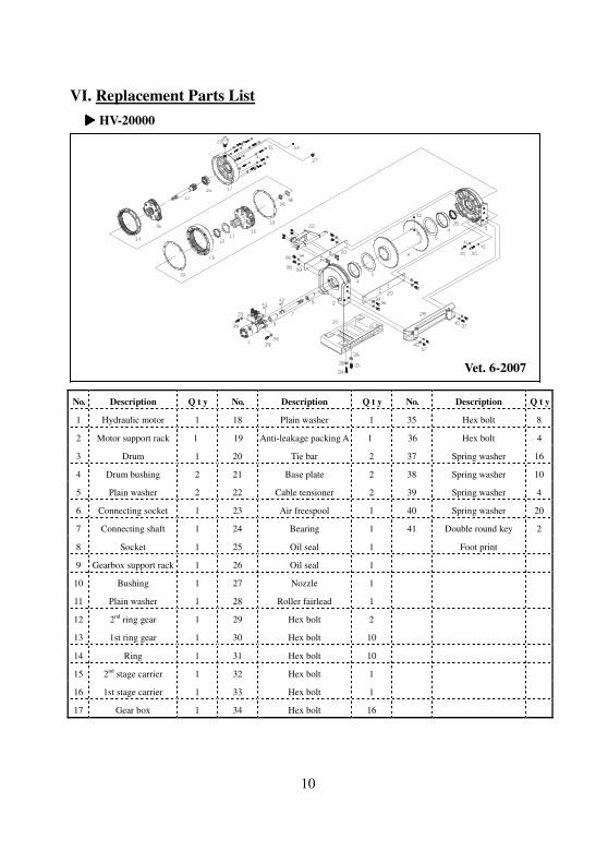
VI. Replacement Parts List
���� HV-20000
Vet. 6-2007
N o . Description Q t y N o . Description Q t y N o . Description Q t y
1 Hydraulic motor 1 18 Plain washer 1 35 Hex bolt 8
2 Motor support rack 1 19 Anti-leakage packing A 1 36 Hex bolt 4
3 Drum 1 20 Tie bar 2 37 Spring washer 16
4 Drum bushing 2 21 Base plate 2 38 Spring washer 10
5 Plain washer 2 22 Cable tensioner 2 39 Spring washer 4
6 Connecting socket 1 23 Air freespool 1 40 Spring washer 20
7 Connecting shaft 1 24 Bearing 1 41 Double round key 2
8 Socket 1 25 Oil seal 1 Foot print
9 Gearbox support rack 1 26 Oil seal 1
10 Bushing 1 27 Nozzle 1
11 Plain washer 1 28 Roller fairlead 1
12 2nd
ring gear 1 29 Hex bolt 2
13 1st ring gear 1 30 Hex bolt 10
14 Ring 1 31 Hex bolt 10
15 2nd
stage carrier 1 32 Hex bolt 1
16 1st stage carrier 1 33 Hex bolt 1
17 Gear box 1 34 Hex bolt 16
Limited Warranty
This Limited Warranty is given by the Comeup Industries Inc. (the "Seller") to
the original purchaser (the "Purchaser") of a Winch specified in this
manual. This Limited Warranty is not transferable to any other party.
The Seller takes the responsibility for all parts and components, with the
exception of the wire rope, motor and electric parts to be free from defects in
materials and workmanship appearing under normal use for as long as the said
Purchaser owns the vehicle that the winch was originally mounted on. Electrical
components are warranted for 1 Year from date of purchase under the same
conditions. Any Winch, which is defective, will be repaired or
replaced without charge to the Purchaser.
Upon discovering any defect, the Purchaser under this Limited Warranty is
requested to return the complete winch and inform the seller or their authorized
distributors of any claims. The Purchaser must provide a copy of the proof of
purchase bearing the winch serial number, date of purchase, owners name and
address, vehicle details and registration number.
The Limited Warranty does not cover any failure that results from
improper installation, operation or the Purchaser’s modification in
design. The winch is designed for vehicle self-recovery use only and
should not be used in industrial applications or for moving people. The
Seller does not warrant them to be suitable for such use.
HV-20000 IM-2007-01-500

11