Hydraulic Pump and Power Systems Division
162
Hydraulic Pump and Power Systems Division Product Range - HY28-2673-01/HPD/US aerospace climate control electromechanical filtration fluid & gas handling hydraulics hydraulics pneumatics pneumatics process control sealing & shielding
Transcript of Hydraulic Pump and Power Systems Division
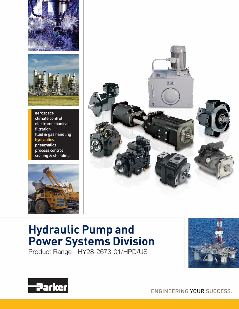
Hydraulic Pump andPower Systems DivisionProduct Range - HY28-2673-01/HPD/US
aerospaceclimate controlelectromechanicalfiltrationfluid & gas handlinghydraulicshydraulicspneumaticspneumaticsprocess controlsealing & shielding
© Copyright 2012, Parker Hannifin Corporation. All Rights Reserved.
WARNING - USER RESPONSIBILITYFAILURE OR IMPROPER SELECTION OR IMPROPER USE OF THE PRODUCTS DESCRIBED HEREIN OR RELATED ITEMS CAN CAUSE DEATH, PERSONAL INJURY AND PROPERTY DAMAGE. This document and other information from Parker-Hannifin Corporation, its subsidiaries and authorized distributors provide product or system options for further investigation by users having technical expertise.
The user, through its own analysis and testing, is solely responsible for making the final selection of the system and components and assuring that all performance, endurance, maintenance, safety and warning requirements of the application are met. The user must analyze all aspects of the application, follow applicable industry standards, and follow the information concerning the product in the current product catalog and in any other materials provided from Parker or its subsidiaries or authorized distributors.
To the extent that Parker or its subsidiaries or authorized distributors provide component or system options based upon data or specifications provided by the user, the user is responsible for determining that such data and specifications are suitable and sufficient for all applications and reasonably foreseeable uses of the components or systems.
OFFER OF SALEThe items described in this document are hereby offered for sale by Parker-Hannifin Corporation, its subsidiaries or its authorized distributor. This offer and its accepteance are governed by the provisions stated in the detailed "Offer of Sale" elsewhere in this document.
Introduction ��������������������������������������������������������������������������������������������������������������������������������������������1-2
Piston Pumps (Open Circuit & Bent Axis)P1 Medium Pressure Mobile Piston Pumps ��������������������������������������������������������������������������������������������������5-16PD Medium Pressure Industrial Piston Pumps ����������������������������������������������������������������������������������������������5-16P2 High Pressure/High Speed Mobile Piston Pumps ����������������������������������������������������������������������������������17-20P3 High Pressure/Super Charged Mobile Piston Pumps ����������������������������������������������������������������������������21-24PVplus High Pressure Industrial Piston Pumps �������������������������������������������������������������������������������������������25-30Premier Series High Pressure/Performance Piston Pumps �������������������������������������������������������������������������31-36VP1 Load Sensing Truck Pumps �����������������������������������������������������������������������������������������������������������������37-40PAVC Medium Pressure/Super Charged Piston Pumps ������������������������������������������������������������������������������41-44F11 Small Frame Fixed Displacement Bent-Axis Pumps/Motors ����������������������������������������������������������������45-48F12 Large Frame Fixed Displacement Bent-Axis Pumps/Motors ����������������������������������������������������������������49-52F1 Fixed Displacement Bent-Axis Truck Pumps/Motors ������������������������������������������������������������������������������53-56F2 Twin Flow Bent-Axis Truck Pumps ����������������������������������������������������������������������������������������������������������57-60
Gold Cup Open & Closed Circuit Pumps & Motors for Hydrostatic Transmissions �����������������������������������������������������������������������������������������������������������������������63-74
Vane PumpsSDV 10/20 Medium Pressure Single Vane Pumps ��������������������������������������������������������������������������������������77-80SDV2010 Medium Pressure Double Vane Pumps ���������������������������������������������������������������������������������������81-84T7A Series High Performance Small Displacement Single Vane Pumps ����������������������������������������������������85-86T6 Series Single, Double & Triple High Performance Vane Pumps �������������������������������������������������������������87-90T7 Series Single, Double & Triple High Performance Vane Pumps �������������������������������������������������������������91-93T67 High Performance Vane Pumps ������������������������������������������������������������������������������������������������������������94-96T6H/T7H Hybrid Technology Variable Piston Fixed Vane Pumps ���������������������������������������������������������������97-100
Motors F11 Small Frame Fixed Displacement Bent-Axis Pumps/Motors ������������������������������������������������������������103-106F12 Large Frame Fixed Displacement Bent-Axis Pumps/Motors ������������������������������������������������������������107-110F1 Fixed Displacement Bent-Axis Truck Pumps/Motors ��������������������������������������������������������������������������111-112V12 Small Frame Variable Displacement Bent-Axis Motors ��������������������������������������������������������������������113-116V14 Large Frame Variable Displacement Bent-Axis Motors ��������������������������������������������������������������������117-120T12 Dual Displacement Bent-Axis Motors �����������������������������������������������������������������������������������������������121-124M3/M4 High Performance Vane Motors ���������������������������������������������������������������������������������������������������125-127M5 High Performance Vane Motors ���������������������������������������������������������������������������������������������������������128-130MR-MRE Low Speed High Torque Small Displacement Radial Piston Motors ����������������������������������������131-134MRT-MRTE-MRTF Low Speed High Torque Large Displacement Radial Piston Motors �����������������������131,135-137MRD-MRDE, MRV-MRVE Low Speed High Torque Variable Displacement Radial Piston Motors ���131,138-140
Gold Cup Open & Closed Circuit Pumps & Motors for Hydrostatic Transmissions �����������������������������������������������������������������������������������������������������������������������63-74
Power Units D-Pak 5 Gallon �����������������������������������������������������������������������������������������������������������������������������������������143-144 H-Pak 10-40 Gallon, 0�9 - 6�3 GPM ���������������������������������������������������������������������������������������������������������145-152 V-Pak 10-40 Gallon, 2 - 15�6 GPM �����������������������������������������������������������������������������������������������������������145-152 V-Pak Low Profile 80 Gallon ���������������������������������������������������������������������������������������������������������������������145-152
ReferenceSAE Flanges and Shafts ���������������������������������������������������������������������������������������������������������������������������������155Formulas and Conversions �����������������������������������������������������������������������������������������������������������������������������156Offer of Sale ����������������������������������������������������������������������������������������������������������������������������������������������������157
(I) = Industrial (M) = Mobile (B) = both Industrial & Mobile
(M) (I) (M) (M) (I) (B) (M) (B) (M) (M) (M) (M)
(M) (M) (M) (M) (M) (M) (B) (B) (B) (B) (B)
(I)(I)(I)(I)
(B)
(B)
(B) (B) (B) (B) (B) (B) (B)
1
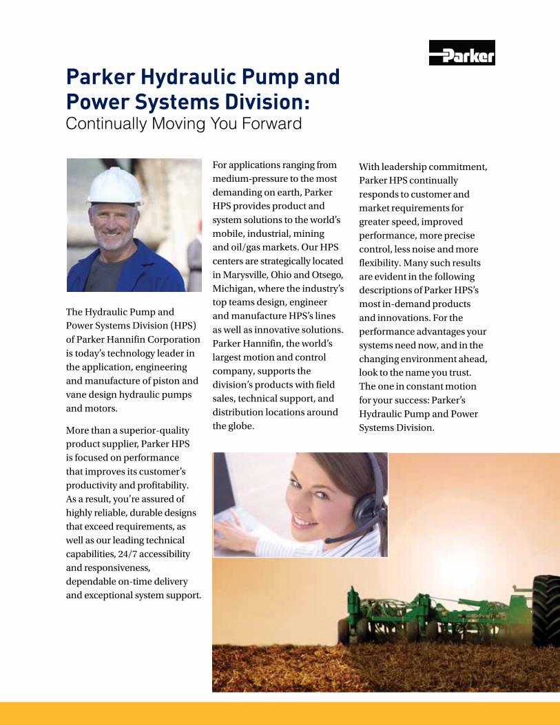
Parker Hydraulic Pump and Power Systems Division:Continually Moving You Forward
The Hydraulic Pump and Power Systems Division (HPS) of Parker Hannifin Corporation is today’s technology leader in the application, engineering and manufacture of piston and vane design hydraulic pumps and motors.
More than a superior-quality product supplier, Parker HPS is focused on performance that improves its customer’s productivity and profitability. As a result, you’re assured of highly reliable, durable designs that exceed requirements, as well as our leading technical capabilities, 24/7 accessibility and responsiveness, dependable on-time delivery and exceptional system support.
For applications ranging from medium-pressure to the most demanding on earth, Parker HPS provides product and system solutions to the world’s mobile, industrial, mining and oil/gas markets. Our HPS centers are strategically located in Marysville, Ohio and Otsego, Michigan, where the industry’s top teams design, engineer and manufacture HPS’s lines as well as innovative solutions. Parker Hannifin, the world’s largest motion and control company, supports the division’s products with field sales, technical support, and distribution locations around the globe.
With leadership commitment, Parker HPS continually responds to customer and market requirements for greater speed, improved performance, more precise control, less noise and more flexibility. Many such results are evident in the following descriptions of Parker HPS’s most in-demand products and innovations. For the performance advantages your systems need now, and in the changing environment ahead, look to the name you trust. The one in constant motion for your success: Parker’s Hydraulic Pump and Power Systems Division.

2
The Powerful Advantages of Parker HPD• Technology Leadership forengineered solutions thatexceed expectations
• Complete Product Lines
• Pumps – open and closedcircuit, axial piston, bent axisand vane
• Pressures – medium, high,extreme
• Motors – fixed and variable;wide speed capability
• Power Units
• Custom Systems
• Added-Value Capabilities
• New-Product Development
• Customized Solutions
• Industry-Leading Lead Times
• 24/7 Access and Response
• Applications Team
• Industry-Leading TechnicalSupport

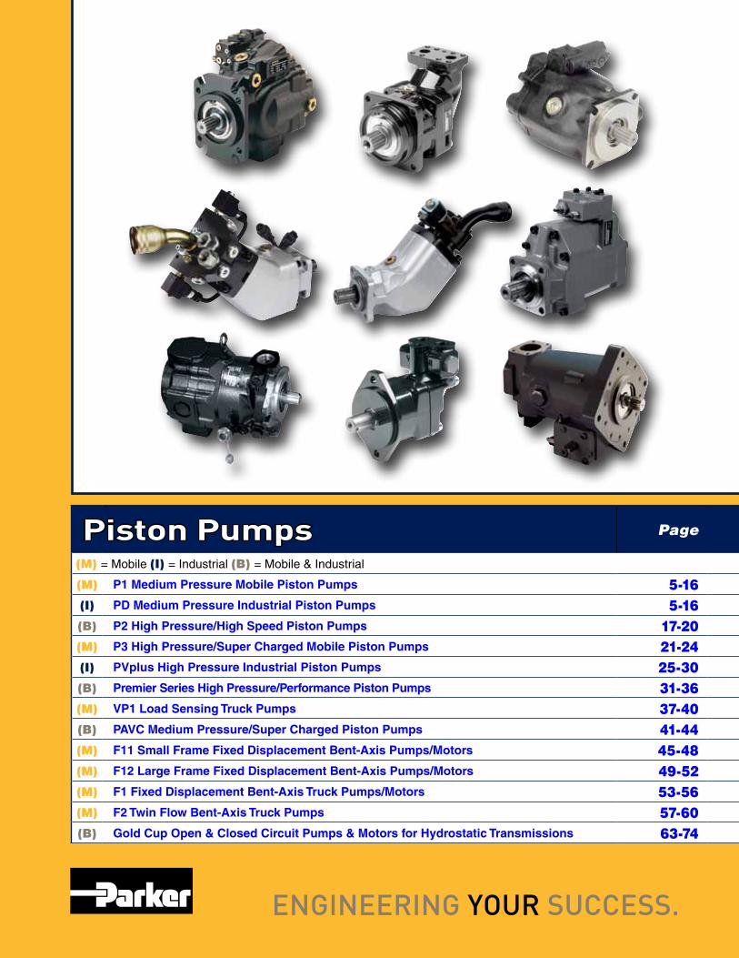
Piston Pumps Page
(M) = Mobile (I) = Industrial (B) = Mobile & Industrial
(M) P1 Medium Pressure Mobile Piston Pumps 5-16(I) PD Medium Pressure Industrial Piston Pumps 5-16(B) P2 High Pressure/High Speed Piston Pumps 17-20(M) P3 High Pressure/Super Charged Mobile Piston Pumps 21-24(I) PVplus High Pressure Industrial Piston Pumps 25-30(B) Premier Series High Pressure/Performance Piston Pumps 31-36(M) VP1 Load Sensing Truck Pumps 37-40(B) PAVC Medium Pressure/Super Charged Piston Pumps 41-44(M) F11 Small Frame Fixed Displacement Bent-Axis Pumps/Motors 45-48(M) F12 Large Frame Fixed Displacement Bent-Axis Pumps/Motors 49-52(M) F1 Fixed Displacement Bent-Axis Truck Pumps/Motors 53-56(M) F2 Twin Flow Bent-Axis Truck Pumps 57-60(B) Gold Cup Open & Closed Circuit Pumps & Motors for Hydrostatic Transmissions 63-74
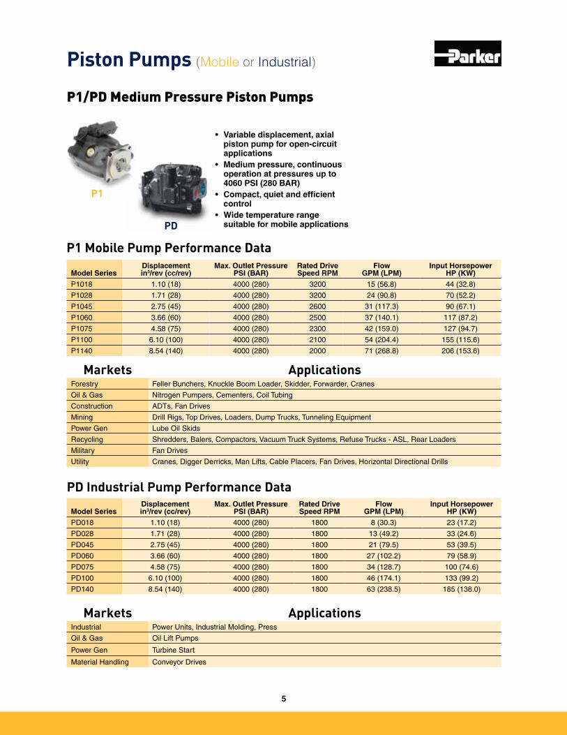
Piston Pumps (Mobile or Industrial)
• Variable displacement, axial piston pump for open-circuit applications
• Medium pressure, continuous operation at pressures up to 4060 PSI (280 BAR)
• Compact, quiet and efficient control
• Wide temperature range suitable for mobile applications
P1/PD Medium Pressure Piston Pumps
Markets ApplicationsForestry Feller Bunchers, Knuckle Boom Loader, Skidder, Forwarder, Cranes
Oil & Gas Nitrogen Pumpers, Cementers, Coil Tubing
Construction ADTs, Fan Drives
Mining Drill Rigs, Top Drives, Loaders, Dump Trucks, Tunneling Equipment
Power Gen Lube Oil Skids
Recycling Shredders, Balers, Compactors, Vacuum Truck Systems, Refuse Trucks - ASL, Rear Loaders
Military Fan Drives
Utility Cranes, Digger Derricks, Man Lifts, Cable Placers, Fan Drives, Horizontal Directional Drills
P1 Mobile Pump Performance Data
Model SeriesDisplacementin3/rev (cc/rev)
Max. Outlet PressurePSI (BAR)
Rated Drive Speed RPM
Flow GPM (LPM)
Input Horsepower HP (KW)
P1018 1�10 (18) 4000 (280) 3200 15 (56�8) 44 (32�8)
P1028 1�71 (28) 4000 (280) 3200 24 (90�8) 70 (52�2)
P1045 2�75 (45) 4000 (280) 2600 31 (117�3) 90 (67�1)
P1060 3�66 (60) 4000 (280) 2500 37 (140�1) 117 (87�2)
P1075 4�58 (75) 4000 (280) 2300 42 (159�0) 127 (94�7)
P1100 6�10 (100) 4000 (280) 2100 54 (204�4) 155 (115�6)
P1140 8�54 (140) 4000 (280) 2000 71 (268�8) 206 (153�6)
PD Industrial Pump Performance Data
Model SeriesDisplacementin3/rev (cc/rev)
Max. Outlet PressurePSI (BAR)
Rated Drive Speed RPM
Flow GPM (LPM)
Input Horsepower HP (KW)
PD018 1�10 (18) 4000 (280) 1800 8 (30�3) 23 (17�2)
PD028 1�71 (28) 4000 (280) 1800 13 (49�2) 33 (24�6)
PD045 2�75 (45) 4000 (280) 1800 21 (79�5) 53 (39�5)
PD060 3�66 (60) 4000 (280) 1800 27 (102�2) 79 (58�9)
PD075 4�58 (75) 4000 (280) 1800 34 (128�7) 100 (74�6)
PD100 6�10 (100) 4000 (280) 1800 46 (174�1) 133 (99�2)
PD140 8�54 (140) 4000 (280) 1800 63 (238�5) 185 (138�0)
Markets ApplicationsIndustrial Power Units, Industrial Molding, Press
Oil & Gas Oil Lift Pumps
Power Gen Turbine Start
Material Handling Conveyor Drives
P1
PD
5
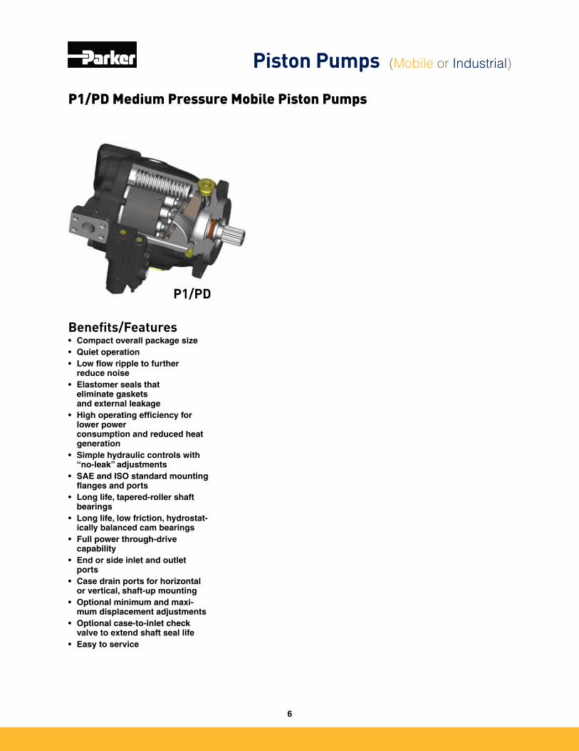
P1/PD Medium Pressure Mobile Piston Pumps
Piston Pumps (Mobile or Industrial)
Benefits/Features• Compact overall package size• Quiet operation• Low flow ripple to further
reduce noise• Elastomer seals that
eliminate gaskets and external leakage
• High operating efficiency for lower power consumption and reduced heat generation
• Simple hydraulic controls with “no-leak” adjustments
• SAE and ISO standard mounting flanges and ports
• Long life, tapered-roller shaft bearings
• Long life, low friction, hydrostat-ically balanced cam bearings
• Full power through-drive capability
• End or side inlet and outlet ports
• Case drain ports for horizontal or vertical, shaft-up mounting
• Optional minimum and maxi-mum displacement adjustments
• Optional case-to-inlet check valve to extend shaft seal life
• Easy to service
P1/PD
6
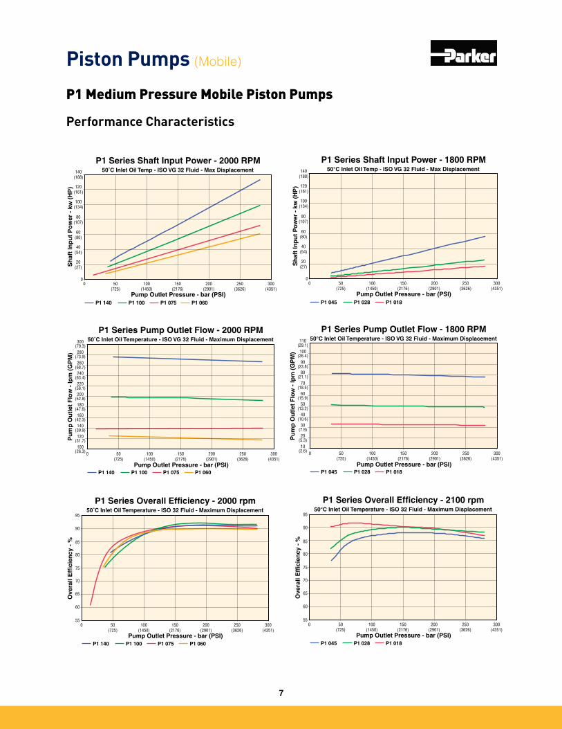
P1 Medium Pressure Mobile Piston Pumps
Piston Pumps (Mobile)
P1 Series Shaft Input Power - 2000 RPM50˚C Inlet Oil Temp - ISO VG 32 Fluid - Max Displacement
0 50 (725)
100(1450)
150(2176)
200(2901)
250(3626)
300(4351)
Pump Outlet Pressure - bar (PSI)
Sh
aft
Inp
ut
Po
wer
- k
w (
HP
)
P1 140
0
20(27)
40(54)
60(80)
80(107)
100(134)
120(161)
140(188)
P1 100 P1 075 P1 060
P1 Series Shaft Input Power - 1800 RPM50°C Inlet Oil Temp - ISO VG 32 Fluid - Max Displacement
0 50(725)
100(1450)
150(2176)
200(2901)
250(3626)
300(4351)
Pump Outlet Pressure - bar (PSI)S
haf
t In
pu
t P
ow
er -
kw
(H
P)
P1 045
0
20(27)
40(54)
60(80)
80(107)
100(134)
120(161)
140(188)
P1 028 P1 018
100(26.3)
120(31.7)
140(39.9)
160(42.3)
180(47.6)
200(52.8)
220(58.1)
240(63.4)
260(68.7)
280(73.9)
300(79.3)
0 50 (725)
100(1450)
150(2176)
200(2901)
250(3626)
300(4351)
Pump Outlet Pressure - bar (PSI)
Pu
mp
Ou
tlet
Flo
w -
lpm
(G
PM
)
P1 Series Pump Outlet Flow - 2000 RPM50˚C Inlet Oil Temperature - ISO VG 32 Fluid - Maximum Displacement
P1 140 P1 100 P1 075 P1 060
10(2.6)
20(5.3)
30(7.9)
40(10.6)
50(13.2)
60(15.9)
70(18.5)
80(21.1)
90(23.8)
100(26.4)
110(29.1)
0 50(725)
100(1450)
150(2176)
200(2901)
250(3626)
300(4351)
Pump Outlet Pressure - bar (PSI)
Pu
mp
Ou
tlet
Flo
w -
lpm
(G
PM
)
P1 Series Pump Outlet Flow - 1800 RPM50°C Inlet Oil Temperature - ISO VG 32 Fluid - Maximum Displacement
P1 045 P1 028 P1 018
P1 Series Overall Efficiency - 2000 rpm50˚C Inlet Oil Temperature - ISO 32 Fluid - Maximum Displacement
0 50 (725)
100(1450)
150(2176)
200(2901)
250(3626)
300(4351)
Pump Outlet Pressure - bar (PSI)
Ove
rall
Eff
icie
ncy
- %
55
60
65
70
75
80
85
90
95
P1 140 P1 100 P1 075 P1 060
P1 Series Overall Efficiency - 2100 rpm50°C Inlet Oil Temperature - ISO 32 Fluid - Maximum Displacement
0 50(725)
100(1450)
150(2176)
200(2901)
250(3626)
300(4351)
Pump Outlet Pressure - bar (PSI)
Ove
rall
Eff
icie
ncy
- %
55
60
65
70
75
80
85
90
95
P1 045 P1 028 P1 018
Performance Characteristics
7
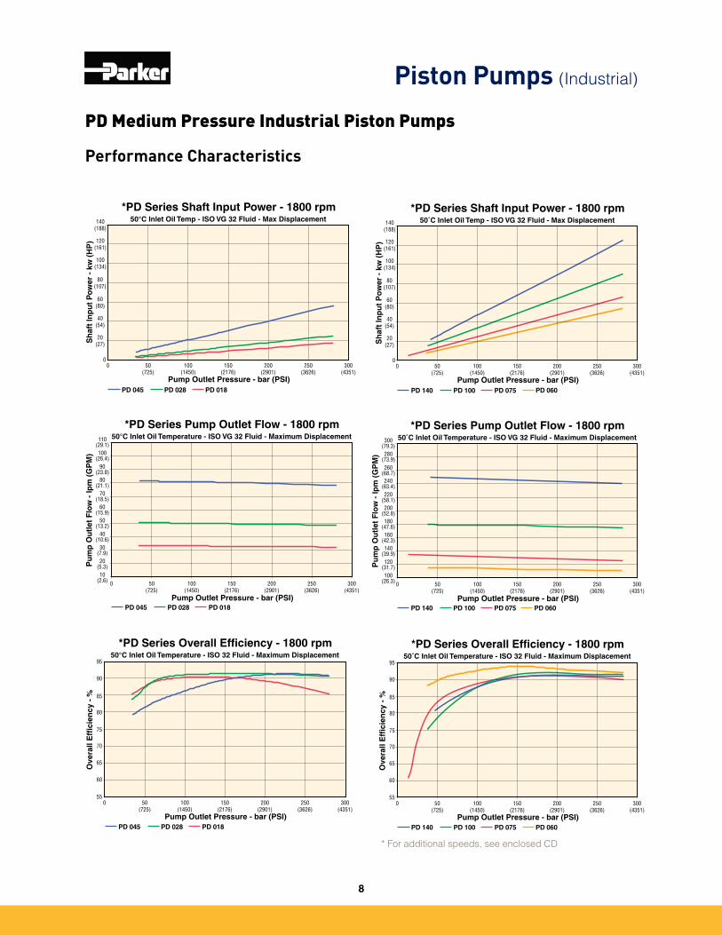
PD Medium Pressure Industrial Piston Pumps
Piston Pumps (Industrial)
* For additional speeds, see enclosed CD
*PD Series Shaft Input Power - 1800 rpm50˚C Inlet Oil Temp - ISO VG 32 Fluid - Max Displacement
0 50 (725)
100(1450)
150(2176)
200(2901)
250(3626)
300(4351)
Pump Outlet Pressure - bar (PSI)S
haf
t In
pu
t P
ow
er -
kw
(H
P)
PD 140
0
20(27)
40(54)
60(80)
80(107)
100(134)
120(161)
140(188)
PD 100 PD 075 PD 060
100(26.3)
120(31.7)
140(39.9)
160(42.3)
180(47.6)
200(52.8)
220(58.1)
240(63.4)
260(68.7)
280(73.9)
300(79.3)
0 50 (725)
100(1450)
150(2176)
200(2901)
250(3626)
300(4351)
Pump Outlet Pressure - bar (PSI)
Pu
mp
Ou
tlet
Flo
w -
lpm
(G
PM
)
*PD Series Pump Outlet Flow - 1800 rpm50˚C Inlet Oil Temperature - ISO VG 32 Fluid - Maximum Displacement
PD 140 PD 100 PD 075 PD 060
*PD Series Overall Efficiency - 1800 rpm50˚C Inlet Oil Temperature - ISO 32 Fluid - Maximum Displacement
0 50 (725)
100(1450)
150(2176)
200(2901)
250(3626)
300(4351)
Pump Outlet Pressure - bar (PSI)
Ove
rall
Eff
icie
ncy
- %
55
60
65
70
75
80
85
90
95
PD 140 PD 100 PD 075 PD 060
*PD Series Shaft Input Power - 1800 rpm50°C Inlet Oil Temp - ISO VG 32 Fluid - Max Displacement
0 50(725)
100(1450)
150(2176)
200(2901)
250(3626)
300(4351)
Pump Outlet Pressure - bar (PSI)
Sh
aft
Inp
ut
Po
wer
- k
w (
HP
)
PD 045
0
20(27)
40(54)
60(80)
80(107)
100(134)
120(161)
140(188)
PD 028 PD 018
10(2.6)
20(5.3)
30(7.9)
40(10.6)
50(13.2)
60(15.9)
70(18.5)
80(21.1)
90(23.8)
100(26.4)
110(29.1)
0 50(725)
100(1450)
150(2176)
200(2901)
250(3626)
300(4351)
Pump Outlet Pressure - bar (PSI)
Pu
mp
Ou
tlet
Flo
w -
lpm
(G
PM
)
*PD Series Pump Outlet Flow - 1800 rpm50°C Inlet Oil Temperature - ISO VG 32 Fluid - Maximum Displacement
PD 045 PD 028 PD 018
*PD Series Overall Efficiency - 1800 rpm50°C Inlet Oil Temperature - ISO 32 Fluid - Maximum Displacement
0 50(725)
100(1450)
150(2176)
200(2901)
250(3626)
300(4351)
Pump Outlet Pressure - bar (PSI)
Ove
rall
Eff
icie
ncy
- %
55
60
65
70
75
80
85
90
95
PD 045 PD 028 PD 018
Performance Characteristics
8
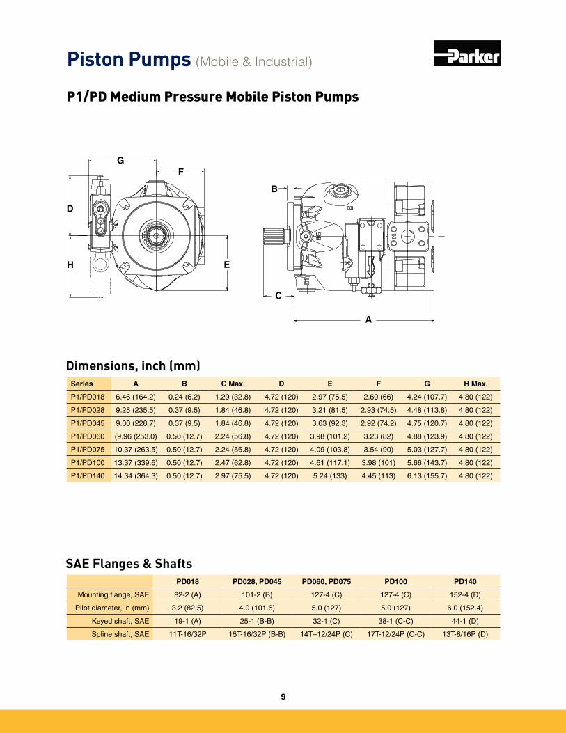
Piston Pumps (Mobile & Industrial)
P1/PD Medium Pressure Mobile Piston Pumps
A
C
B
E
FG
D
H
Dimensions, inch (mm)
SAE Flanges & Shafts
Series A B C Max. D E F G H Max.
P1/PD018 6�46 (164�2) 0�24 (6�2) 1�29 (32�8) 4�72 (120) 2�97 (75�5) 2�60 (66) 4�24 (107�7) 4�80 (122)
P1/PD028 9�25 (235�5) 0�37 (9�5) 1�84 (46�8) 4�72 (120) 3�21 (81�5) 2�93 (74�5) 4�48 (113�8) 4�80 (122)
P1/PD045 9�00 (228�7) 0�37 (9�5) 1�84 (46�8) 4�72 (120) 3�63 (92�3) 2�92 (74�2) 4�75 (120�7) 4�80 (122)
P1/PD060 (9�96 (253�0) 0�50 (12�7) 2�24 (56�8) 4�72 (120) 3�98 (101�2) 3�23 (82) 4�88 (123�9) 4�80 (122)
P1/PD075 10�37 (263�5) 0�50 (12�7) 2�24 (56�8) 4�72 (120) 4�09 (103�8) 3�54 (90) 5�03 (127�7) 4�80 (122)
P1/PD100 13�37 (339�6) 0�50 (12�7) 2�47 (62�8) 4�72 (120) 4�61 (117�1) 3�98 (101) 5�66 (143�7) 4�80 (122)
P1/PD140 14�34 (364�3) 0�50 (12�7) 2�97 (75�5) 4�72 (120) 5�24 (133) 4�45 (113) 6�13 (155�7) 4�80 (122)
PD018 PD028, PD045 PD060, PD075 PD100 PD140
Mounting flange, SAE 82-2 (A) 101-2 (B) 127-4 (C) 127-4 (C) 152-4 (D)
Pilot diameter, in (mm) 3�2 (82�5) 4�0 (101�6) 5�0 (127) 5�0 (127) 6�0 (152�4)
Keyed shaft, SAE 19-1 (A) 25-1 (B-B) 32-1 (C) 38-1 (C-C) 44-1 (D)
Spline shaft, SAE 11T-16/32P 15T-16/32P (B-B) 14T–12/24P (C) 17T-12/24P (C-C) 13T-8/16P (D)
9
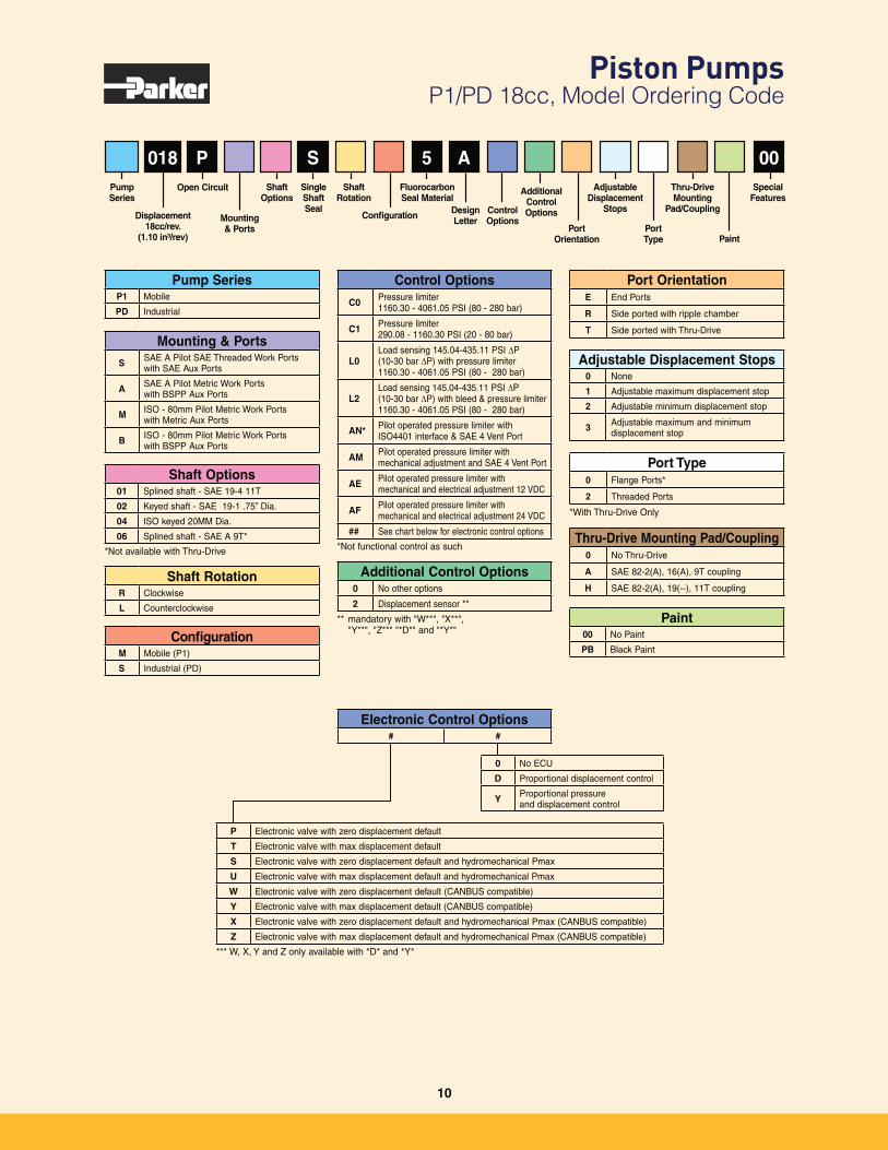
Piston Pumps P1/PD 18cc, Model Ordering Code
Paint00 No Paint
PB Black Paint
018
Shaft Options01 Splined shaft - SAE 19-4 11T
02 Keyed shaft - SAE 19-1 .75” Dia.
04 ISO keyed 20MM Dia.
06 Splined shaft - SAE A 9T*
*Not available with Thru-Drive
Shaft RotationR Clockwise
L Counterclockwise
Pump SeriesP1 Mobile
PD Industrial
ConfigurationM Mobile (P1)
S Industrial (PD)
Mounting & PortsS SAE A Pilot SAE Threaded Work Ports
with SAE Aux Ports
A SAE A Pilot Metric Work Ports with BSPP Aux Ports
M ISO - 80mm Pilot Metric Work Ports with Metric Aux Ports
B ISO - 80mm Pilot Metric Work Ports with BSPP Aux Ports
P S 5 A 00Adjustable
Displacement Stops
Port Type
Thru-Drive Mounting
Pad/Coupling
Paint
Special Features
Adjustable Displacement Stops0 None
1 Adjustable maximum displacement stop
2 Adjustable minimum displacement stop
3 Adjustable maximum and minimum displacement stop
Pump Series
Port OrientationE End Ports
R Side ported with ripple chamber
T Side ported with Thru-Drive
Thru-Drive Mounting Pad/Coupling0 No Thru-Drive
A SAE 82-2(A), 16(A), 9T coupling
H SAE 82-2(A), 19(--), 11T coupling
Port Type0 Flange Ports*
2 Threaded Ports
*With Thru-Drive Only
Displacement 18cc/rev.
(1.10 in³/rev)
Mounting & Ports
Open Circuit
Port Orientation
Shaft Rotation
Design Letter
Additional Control OptionsControl
OptionsConfiguration
Single Shaft Seal
Shaft Options
Fluorocarbon Seal Material
Control Options
C0 Pressure limiter 1160.30 - 4061.05 PSI (80 - 280 bar)
C1 Pressure limiter 290.08 - 1160.30 PSI (20 - 80 bar)
L0Load sensing 145.04-435.11 PSI P (10-30 bar P) with pressure limiter 1160.30 - 4061.05 PSI (80 - 280 bar)
L2Load sensing 145.04-435.11 PSI P (10-30 bar P) with bleed & pressure limiter 1160.30 - 4061.05 PSI (80 - 280 bar)
AN* Pilot operated pressure limiter with ISO4401 interface & SAE 4 Vent Port
AM Pilot operated pressure limiter with mechanical adjustment and SAE 4 Vent Port
AE Pilot operated pressure limiter with mechanical and electrical adjustment 12 VDC
AF Pilot operated pressure limiter with mechanical and electrical adjustment 24 VDC
## See chart below for electronic control options
*Not functional control as such
P Electronic valve with zero displacement default
T Electronic valve with max displacement default
S Electronic valve with zero displacement default and hydromechanical Pmax
U Electronic valve with max displacement default and hydromechanical Pmax
W Electronic valve with zero displacement default (CANBUS compatible)
Y Electronic valve with max displacement default (CANBUS compatible)
X Electronic valve with zero displacement default and hydromechanical Pmax (CANBUS compatible)
Z Electronic valve with max displacement default and hydromechanical Pmax (CANBUS compatible)
*** W, X, Y and Z only available with *D* and *Y*
0 No ECU
D Proportional displacement control
Y Proportional pressure and displacement control
Electronic Control Options# #
Additional Control Options0 No other options
2 Displacement sensor **
** mandatory with "W**", "X**", "Y**", "Z**" "*D*" and "*Y*"
10
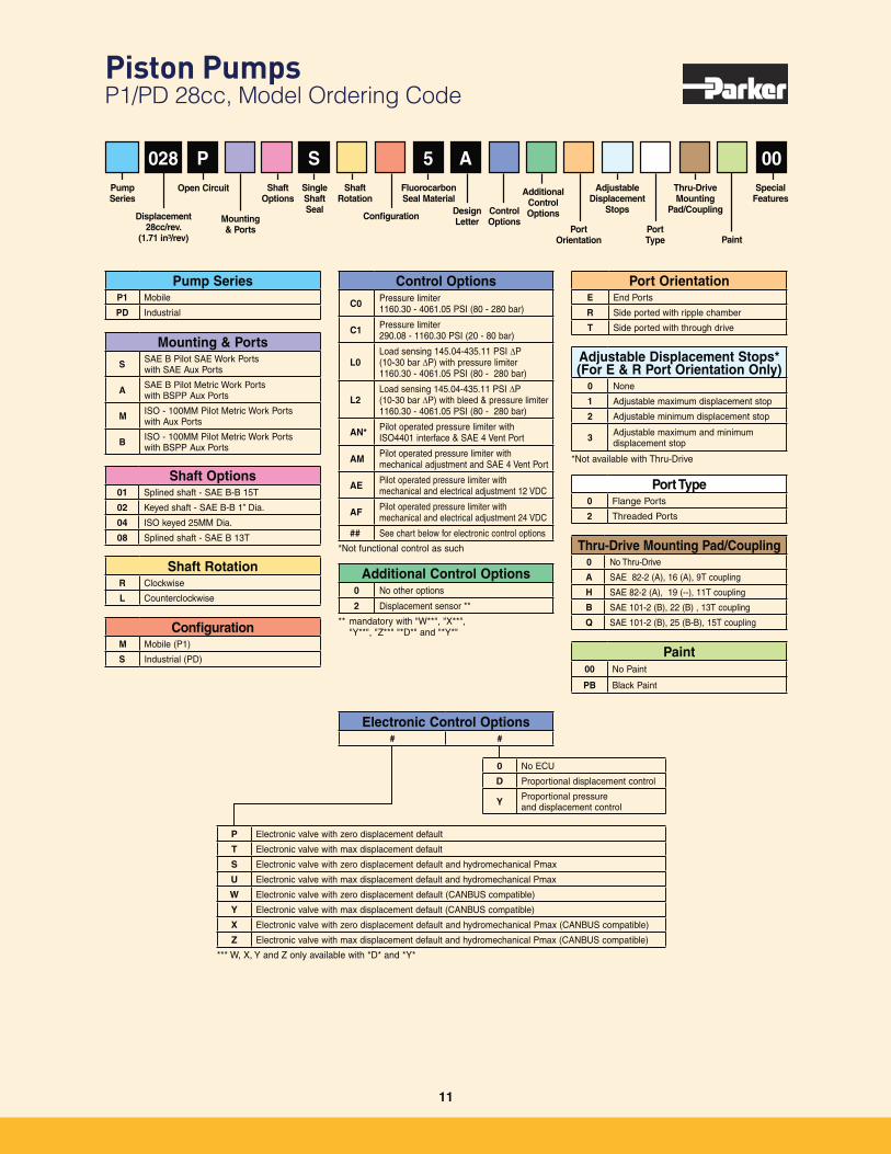
Piston Pumps P1/PD 28cc, Model Ordering Code
Paint00 No Paint
PB Black Paint
Shaft Options01 Splined shaft - SAE B-B 15T
02 Keyed shaft - SAE B-B 1” Dia.
04 ISO keyed 25MM Dia.
08 Splined shaft - SAE B 13T
Shaft RotationR Clockwise
L Counterclockwise
Pump SeriesP1 Mobile
PD Industrial
ConfigurationM Mobile (P1)
S Industrial (PD)
Mounting & PortsS SAE B Pilot SAE Work Ports
with SAE Aux Ports
A SAE B Pilot Metric Work Ports with BSPP Aux Ports
M ISO - 100MM Pilot Metric Work Ports with Aux Ports
B ISO - 100MM Pilot Metric Work Ports with BSPP Aux Ports
Adjustable Displacement Stops*(For E & R Port Orientation Only)
0 None
1 Adjustable maximum displacement stop
2 Adjustable minimum displacement stop
3 Adjustable maximum and minimum displacement stop
*Not available with Thru-Drive
Port OrientationE End Ports
R Side ported with ripple chamber
T Side ported with through drive
Control Options
C0 Pressure limiter 1160.30 - 4061.05 PSI (80 - 280 bar)
C1 Pressure limiter 290.08 - 1160.30 PSI (20 - 80 bar)
L0Load sensing 145.04-435.11 PSI P (10-30 bar P) with pressure limiter 1160.30 - 4061.05 PSI (80 - 280 bar)
L2Load sensing 145.04-435.11 PSI P (10-30 bar P) with bleed & pressure limiter 1160.30 - 4061.05 PSI (80 - 280 bar)
AN* Pilot operated pressure limiter with ISO4401 interface & SAE 4 Vent Port
AM Pilot operated pressure limiter with mechanical adjustment and SAE 4 Vent Port
AE Pilot operated pressure limiter with mechanical and electrical adjustment 12 VDC
AF Pilot operated pressure limiter with mechanical and electrical adjustment 24 VDC
## See chart below for electronic control options
*Not functional control as such
028 P S 5 A 00Adjustable
Displacement Stops
Port Type
Thru-Drive Mounting
Pad/Coupling
Paint
Special Features
Pump Series
Displacement 28cc/rev.
(1.71 in³/rev)
Mounting & Ports
Open Circuit
Port Orientation
Shaft Rotation
Design Letter
Additional Control OptionsControl
OptionsConfiguration
Single Shaft Seal
Shaft Options
Fluorocarbon Seal Material
Thru-Drive Mounting Pad/Coupling0 No Thru-Drive
A SAE 82-2 (A), 16 (A), 9T coupling
H SAE 82-2 (A), 19 (--), 11T coupling
B SAE 101-2 (B), 22 (B) , 13T coupling
Q SAE 101-2 (B), 25 (B-B), 15T coupling
Port Type0 Flange Ports
2 Threaded Ports
P Electronic valve with zero displacement default
T Electronic valve with max displacement default
S Electronic valve with zero displacement default and hydromechanical Pmax
U Electronic valve with max displacement default and hydromechanical Pmax
W Electronic valve with zero displacement default (CANBUS compatible)
Y Electronic valve with max displacement default (CANBUS compatible)
X Electronic valve with zero displacement default and hydromechanical Pmax (CANBUS compatible)
Z Electronic valve with max displacement default and hydromechanical Pmax (CANBUS compatible)
*** W, X, Y and Z only available with *D* and *Y*
0 No ECU
D Proportional displacement control
Y Proportional pressure and displacement control
Electronic Control Options# #
Additional Control Options0 No other options
2 Displacement sensor **
** mandatory with "W**", "X**", "Y**", "Z**" "*D*" and "*Y*"
11
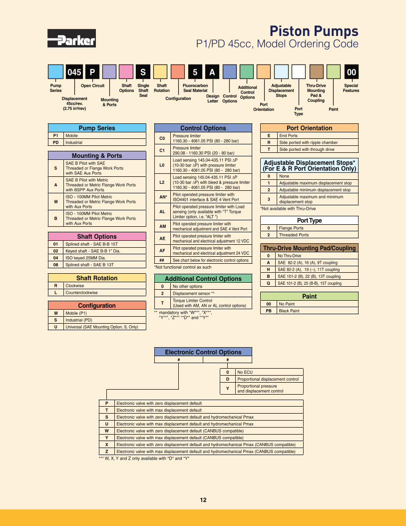
Piston Pumps P1/PD 45cc, Model Ordering Code
Paint00 No Paint
PB Black Paint
Thru-Drive Mounting Pad/Coupling0 No Thru-Drive
A SAE 82-2 (A), 16 (A), 9T coupling
H SAE 82-2 (A), 19 (--), 11T coupling
B SAE 101-2 (B), 22 (B), 13T coupling
Q SAE 101-2 (B), 25 (B-B), 15T coupling
045
Shaft Options01 Splined shaft - SAE B-B 15T
02 Keyed shaft - SAE B-B 1” Dia.
04 ISO keyed 25MM Dia.
08 Splined shaft - SAE B 13T
Shaft RotationR Clockwise
L Counterclockwise
Pump SeriesP1 Mobile
PD Industrial
ConfigurationM Mobile (P1)
S Industrial (PD)
U Universal (SAE Mounting Option, S, Only)
Mounting & Ports
SSAE B Pilot with SAE Threaded or Flange Work Ports with SAE Aux Ports
ASAE B Pilot with Metric Threaded or Metric Flange Work Ports with BSPP Aux Ports
MISO - 100MM Pilot Metric Threaded or Metric Flange Work Ports with Aux Ports
BISO - 100MM Pilot Metric Threaded or Metric Flange Work Ports with Aux Ports
Additional Control Options0 No other options
2 Displacement sensor **
T Torque Limiter Control (Used with AM, AN or AL control options)
** mandatory with "W**", "X**", "Y**", "Z**" "*D*" and "*Y*"
Port Type0 Flange Ports
2 Threaded Ports
P S 5 A 00Adjustable
Displacement Stops
Port Type
Thru-Drive Mounting
Pad & Coupling
Paint
Special Features
Adjustable Displacement Stops*(For E & R Port Orientation Only)
0 None
1 Adjustable maximum displacement stop
2 Adjustable minimum displacement stop
3 Adjustable maximum and minimum displacement stop
*Not available with Thru-Drive
Pump Series
Port OrientationE End Ports
R Side ported with ripple chamber
T Side ported with through drive
Displacement 45cc/rev.
(2.75 in³/rev)
Mounting & Ports
Open Circuit
Port Orientation
Shaft Rotation
Design Letter
Additional Control OptionsControl
OptionsConfiguration
Single Shaft Seal
Shaft Options
Fluorocarbon Seal Material
Control Options
C0 Pressure limiter 1160.30 - 4061.05 PSI (80 - 280 bar)
C1 Pressure limiter 290.08 - 1160.30 PSI (20 - 80 bar)
L0Load sensing 145.04-435.11 PSI P (10-30 bar P) with pressure limiter 1160.30 - 4061.05 PSI (80 - 280 bar)
L2Load sensing 145.04-435.11 PSI P (10-30 bar P) with bleed & pressure limiter 1160.30 - 4061.05 PSI (80 - 280 bar)
AN* Pilot operated pressure limiter with ISO4401 interface & SAE 4 Vent Port
ALPilot operated pressure limiter with Load sensing (only available with "T" Torque Limiter option, i.e. "ALT ")
AM Pilot operated pressure limiter with mechanical adjustment and SAE 4 Vent Port
AE Pilot operated pressure limiter with mechanical and electrical adjustment 12 VDC
AF Pilot operated pressure limiter with mechanical and electrical adjustment 24 VDC
## See chart below for electronic control options
*Not functional control as such
P Electronic valve with zero displacement default
T Electronic valve with max displacement default
S Electronic valve with zero displacement default and hydromechanical Pmax
U Electronic valve with max displacement default and hydromechanical Pmax
W Electronic valve with zero displacement default (CANBUS compatible)
Y Electronic valve with max displacement default (CANBUS compatible)
X Electronic valve with zero displacement default and hydromechanical Pmax (CANBUS compatible)
Z Electronic valve with max displacement default and hydromechanical Pmax (CANBUS compatible)
*** W, X, Y and Z only available with *D* and *Y*
0 No ECU
D Proportional displacement control
Y Proportional pressure and displacement control
Electronic Control Options# #
12
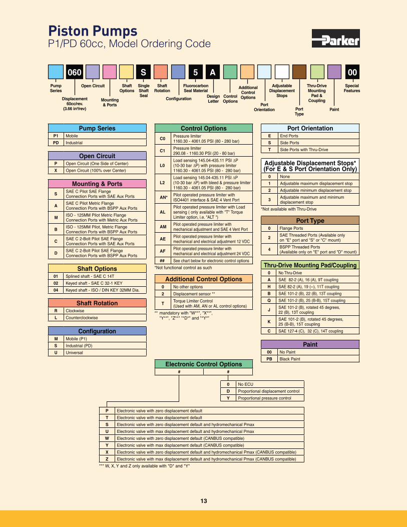
Piston Pumps P1/PD 60cc, Model Ordering Code
Additional Control Options0 No other options
2 Displacement sensor **
T Torque Limiter Control (Used with AM, AN or AL control options)
** mandatory with "W**", "X**", "Y**", "Z**" "*D*" and "*Y*"
Control Options
C0 Pressure limiter 1160.30 - 4061.05 PSI (80 - 280 bar)
C1 Pressure limiter 290.08 - 1160.30 PSI (20 - 80 bar)
L0Load sensing 145.04-435.11 PSI P (10-30 bar P) with pressure limiter 1160.30 - 4061.05 PSI (80 - 280 bar)
L2Load sensing 145.04-435.11 PSI P (10-30 bar P) with bleed & pressure limiter 1160.30 - 4061.05 PSI (80 - 280 bar)
AN* Pilot operated pressure limiter with ISO4401 interface & SAE 4 Vent Port
ALPilot operated pressure limiter with Load sensing ( only available with "T" Torque Limiter option, i.e. "ALT ")
AM Pilot operated pressure limiter with mechanical adjustment and SAE 4 Vent Port
AE Pilot operated pressure limiter with mechanical and electrical adjustment 12 VDC
AF Pilot operated pressure limiter with mechanical and electrical adjustment 24 VDC
## See chart below for electronic control options
*Not functional control as such
060
Shaft Options01 Splined shaft - SAE C 14T
02 Keyed shaft - SAE C 32-1 KEY
04 Keyed shaft - ISO / DIN KEY 32MM Dia.
Shaft RotationR Clockwise
L Counterclockwise
Pump SeriesP1 Mobile
PD Industrial
ConfigurationM Mobile (P1)
S Industrial (PD)
U Universal
Mounting & PortsS SAE C Pilot SAE Flange
Connection Ports with SAE Aux Ports
A SAE C Pilot Metric Flange Connection Ports with BSPP Aux Ports
M ISO - 125MM Pilot Metric Flange Connection Ports with Metric Aux Ports
B ISO - 125MM Pilot, Metric Flange Connection Ports with BSPP Aux Ports
C SAE C 2-Bolt Pilot SAE Flange Connection Ports with SAE Aux Ports
D SAE C 2-Bolt Pilot SAE Flange Connection Ports with BSPP Aux Ports
Open CircuitP Open Circuit (One Side of Center)
X Open Circuit (100% over Center)
Port Type0 Flange Ports
2 SAE Threaded Ports (Available only on "E" port and "S" or "C" mount)
4 BSPP Threaded Ports (Available only on "E" port and "D" mount)
S 5 A 00Adjustable
Displacement Stops
Port Type
Thru-Drive Mounting
Pad & Coupling
Paint
Special Features
Adjustable Displacement Stops*(For E & S Port Orientation Only)
0 None
1 Adjustable maximum displacement stop
2 Adjustable minimum displacement stop
3 Adjustable maximum and minimum displacement stop
*Not available with Thru-Drive
Pump Series
Port OrientationE End Ports
S Side Ports
T Side Ports with Thru-Drive
Displacement 60cc/rev.
(3.66 in³/rev)
Mounting & Ports
Open Circuit
Port Orientation
Shaft Rotation
Design Letter
Additional Control OptionsControl
OptionsConfiguration
Single Shaft Seal
Shaft Options
Fluorocarbon Seal Material
Paint00 No Paint
PB Black Paint
Thru-Drive Mounting Pad/Coupling0 No Thru-Drive
A SAE 82-2 (A), 16 (A), 9T coupling
H SAE 82-2 (A), 19 (--), 11T coupling
B SAE 101-2 (B), 22 (B), 13T coupling
Q SAE 101-2 (B), 25 (B-B), 15T coupling
J SAE 101-2 (B), rotated 45 degrees, 22 (B), 13T coupling
K SAE 101-2 (B), rotated 45 degrees, 25 (B-B), 15T coupling
C SAE 127-4 (C), 32 (C), 14T coupling
P Electronic valve with zero displacement default
T Electronic valve with max displacement default
S Electronic valve with zero displacement default and hydromechanical Pmax
U Electronic valve with max displacement default and hydromechanical Pmax
W Electronic valve with zero displacement default (CANBUS compatible)
Y Electronic valve with max displacement default (CANBUS compatible)
X Electronic valve with zero displacement default and hydromechanical Pmax (CANBUS compatible)
Z Electronic valve with max displacement default and hydromechanical Pmax (CANBUS compatible)
*** W, X, Y and Z only available with *D* and *Y*
0 No ECU
D Proportional displacement control
Y Proportional pressure control
Electronic Control Options# #
13
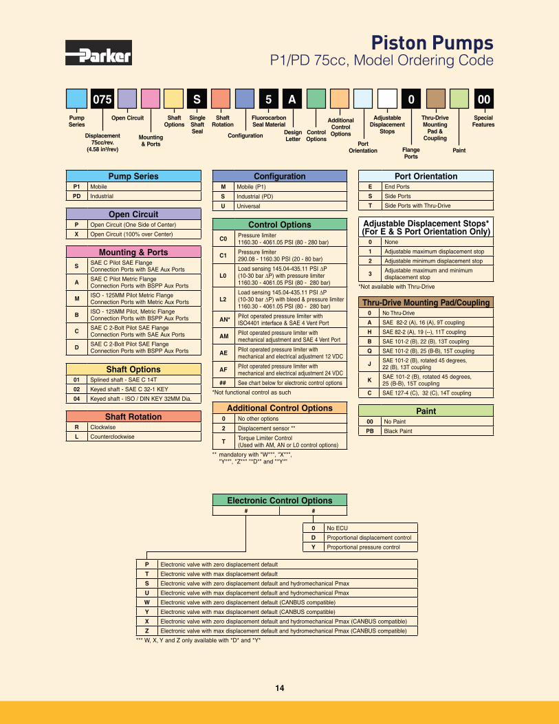
Piston Pumps P1/PD 75cc, Model Ordering Code
Paint00 No Paint
PB Black Paint
Thru-Drive Mounting Pad/Coupling0 No Thru-Drive
A SAE 82-2 (A), 16 (A), 9T coupling
H SAE 82-2 (A), 19 (--), 11T coupling
B SAE 101-2 (B), 22 (B), 13T coupling
Q SAE 101-2 (B), 25 (B-B), 15T coupling
J SAE 101-2 (B), rotated 45 degrees, 22 (B), 13T coupling
K SAE 101-2 (B), rotated 45 degrees, 25 (B-B), 15T coupling
C SAE 127-4 (C), 32 (C), 14T coupling
075 S 5 A 0 00Adjustable
Displacement Stops
Thru-Drive Mounting
Pad & Coupling
Paint
Special Features
Pump Series
Displacement 75cc/rev.
(4.58 in³/rev)
Mounting & Ports
Open Circuit
Port Orientation
Shaft Rotation
Design Letter
Additional Control OptionsControl
OptionsConfiguration
Single Shaft Seal
Shaft Options
Fluorocarbon Seal Material
Control Options
C0 Pressure limiter 1160.30 - 4061.05 PSI (80 - 280 bar)
C1 Pressure limiter 290.08 - 1160.30 PSI (20 - 80 bar)
L0Load sensing 145.04-435.11 PSI P (10-30 bar P) with pressure limiter 1160.30 - 4061.05 PSI (80 - 280 bar)
L2Load sensing 145.04-435.11 PSI P (10-30 bar P) with bleed & pressure limiter 1160.30 - 4061.05 PSI (80 - 280 bar)
AN* Pilot operated pressure limiter with ISO4401 interface & SAE 4 Vent Port
AM Pilot operated pressure limiter with mechanical adjustment and SAE 4 Vent Port
AE Pilot operated pressure limiter with mechanical and electrical adjustment 12 VDC
AF Pilot operated pressure limiter with mechanical and electrical adjustment 24 VDC
## See chart below for electronic control options
*Not functional control as such
Shaft Options01 Splined shaft - SAE C 14T
02 Keyed shaft - SAE C 32-1 KEY
04 Keyed shaft - ISO / DIN KEY 32MM Dia.
Shaft RotationR Clockwise
L Counterclockwise
Pump SeriesP1 Mobile
PD Industrial
Open CircuitP Open Circuit (One Side of Center)
X Open Circuit (100% over Center)
ConfigurationM Mobile (P1)
S Industrial (PD)
U Universal
Mounting & PortsS SAE C Pilot SAE Flange
Connection Ports with SAE Aux Ports
A SAE C Pilot Metric Flange Connection Ports with BSPP Aux Ports
M ISO - 125MM Pilot Metric Flange Connection Ports with Metric Aux Ports
B ISO - 125MM Pilot, Metric Flange Connection Ports with BSPP Aux Ports
C SAE C 2-Bolt Pilot SAE Flange Connection Ports with SAE Aux Ports
D SAE C 2-Bolt Pilot SAE Flange Connection Ports with BSPP Aux Ports
Adjustable Displacement Stops*(For E & S Port Orientation Only)
0 None
1 Adjustable maximum displacement stop
2 Adjustable minimum displacement stop
3 Adjustable maximum and minimum displacement stop
*Not available with Thru-Drive
Port OrientationE End Ports
S Side Ports
T Side Ports with Thru-Drive
Flange Ports
P Electronic valve with zero displacement default
T Electronic valve with max displacement default
S Electronic valve with zero displacement default and hydromechanical Pmax
U Electronic valve with max displacement default and hydromechanical Pmax
W Electronic valve with zero displacement default (CANBUS compatible)
Y Electronic valve with max displacement default (CANBUS compatible)
X Electronic valve with zero displacement default and hydromechanical Pmax (CANBUS compatible)
Z Electronic valve with max displacement default and hydromechanical Pmax (CANBUS compatible)
*** W, X, Y and Z only available with *D* and *Y*
0 No ECU
D Proportional displacement control
Y Proportional pressure control
Electronic Control Options# #
Additional Control Options0 No other options
2 Displacement sensor **
T Torque Limiter Control (Used with AM, AN or L0 control options)
** mandatory with "W**", "X**", "Y**", "Z**" "*D*" and "*Y*"
14
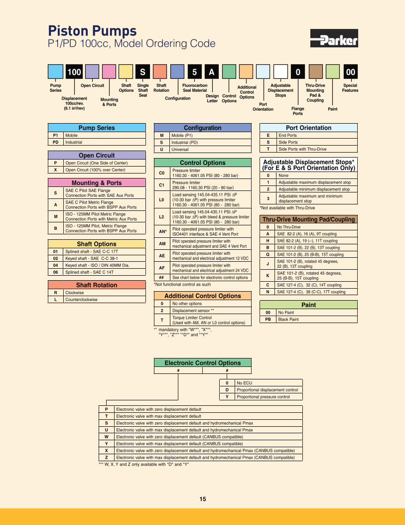
Piston Pumps P1/PD 100cc, Model Ordering Code
Paint00 No Paint
PB Black Paint
Thru-Drive Mounting Pad/Coupling0 No Thru-Drive
A SAE 82-2 (A), 16 (A), 9T coupling
H SAE 82-2 (A), 19 (--), 11T coupling
B SAE 101-2 (B), 22 (B), 13T coupling
Q SAE 101-2 (B), 25 (B-B), 15T coupling
J SAE 101-2 (B), rotated 45 degrees, 22 (B), 13T coupling
K SAE 101-2 (B), rotated 45 degrees, 25 (B-B), 15T coupling
C SAE 127-4 (C), 32 (C), 14T coupling
N SAE 127-4 (C), 38 (C-C), 17T coupling
100
Shaft Options01 Splined shaft - SAE C-C 17T
02 Keyed shaft - SAE C-C 38-1
04 Keyed shaft - ISO / DIN 40MM Dia.
06 Splined shaft - SAE C 14T
Pump SeriesP1 Mobile
PD Industrial
Mounting & PortsS SAE C Pilot SAE Flange
Connection Ports with SAE Aux Ports
A SAE C Pilot Metric Flange Connection Ports with BSPP Aux Ports
M ISO - 125MM Pilot Metric Flange Connection Ports with Metric Aux Ports
B ISO - 125MM Pilot, Metric Flange Connection Ports with BSPP Aux Ports
S 5 A 0 00Adjustable
Displacement Stops
Thru-Drive Mounting
Pad & Coupling
Paint
Special Features
Pump Series
Displacement 100cc/rev.
(6.1 in³/rev)
Mounting & Ports
Open Circuit
Port Orientation
Shaft Rotation
Design Letter
Additional Control OptionsControl
OptionsConfiguration
Single Shaft Seal
Shaft Options
Fluorocarbon Seal Material
Control Options
C0 Pressure limiter 1160.30 - 4061.05 PSI (80 - 280 bar)
C1 Pressure limiter 290.08 - 1160.30 PSI (20 - 80 bar)
L0Load sensing 145.04-435.11 PSI P (10-30 bar P) with pressure limiter 1160.30 - 4061.05 PSI (80 - 280 bar)
L2Load sensing 145.04-435.11 PSI P (10-30 bar P) with bleed & pressure limiter 1160.30 - 4061.05 PSI (80 - 280 bar)
AN* Pilot operated pressure limiter with ISO4401 interface & SAE 4 Vent Port
AM Pilot operated pressure limiter with mechanical adjustment and SAE 4 Vent Port
AE Pilot operated pressure limiter with mechanical and electrical adjustment 12 VDC
AF Pilot operated pressure limiter with mechanical and electrical adjustment 24 VDC
## See chart below for electronic control options
*Not functional control as suchShaft RotationR Clockwise
L Counterclockwise
ConfigurationM Mobile (P1)
S Industrial (PD)
U Universal
Adjustable Displacement Stops*(For E & S Port Orientation Only)
0 None
1 Adjustable maximum displacement stop
2 Adjustable minimum displacement stop
3 Adjustable maximum and minimum displacement stop
*Not available with Thru-Drive
Port OrientationE End Ports
S Side Ports
T Side Ports with Thru-Drive
Flange Ports
Open CircuitP Open Circuit (One Side of Center)
X Open Circuit (100% over Center)
P Electronic valve with zero displacement default
T Electronic valve with max displacement default
S Electronic valve with zero displacement default and hydromechanical Pmax
U Electronic valve with max displacement default and hydromechanical Pmax
W Electronic valve with zero displacement default (CANBUS compatible)
Y Electronic valve with max displacement default (CANBUS compatible)
X Electronic valve with zero displacement default and hydromechanical Pmax (CANBUS compatible)
Z Electronic valve with max displacement default and hydromechanical Pmax (CANBUS compatible)
*** W, X, Y and Z only available with *D* and *Y*
0 No ECU
D Proportional displacement control
Y Proportional pressure control
Electronic Control Options# #
Additional Control Options0 No other options
2 Displacement sensor **
T Torque Limiter Control (Used with AM, AN or L0 control options)
** mandatory with "W**", "X**", "Y**", "Z**" "*D*" and "*Y*"
15
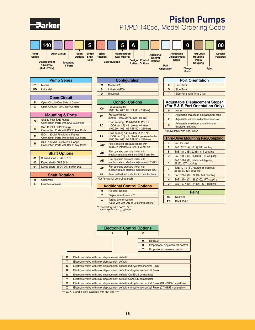
Piston Pumps P1/PD 140cc, Model Ordering Code
Thru-Drive Mounting Pad/Coupling0 No Thru-Drive
A SAE 82-2 (A), 16 (A), 9T coupling
B SAE 101-2 (B), 22 (B), 11T coupling
Q SAE 101-2 (B), 25 (B-B), 13T coupling
J SAE 101-2 (B), rotated 45 degrees, 22 (B), 15T coupling
K SAE 101-2 (B), rotated 45 degrees, 25 (B-B), 13T coupling
C SAE 127-4 (C), 32 (C), 14T coupling
N SAE 127-4 (C), 38 (C-C), 17T coupling
D SAE 152-4 (D), 44 (D), 13T coupling
140
Shaft Options01 Splined shaft - SAE D 13T
02 Keyed shaft - SAE D 44-1
04 Keyed shaft - ISO / DIN 50MM Dia.
Mounting & PortsS SAE D Pilot SAE Flange
Connection Ports with SAE Aux Ports
A SAE D Pilot BSPP Flange Connection Ports with BSPP Aux Ports
M ISO - 180MM Pilot Metric Flange Connection Ports with Metric Aux Ports
B ISO - 180MM Pilot Metric Flange Connection Ports with BSPP Aux Ports
S 5 A 0 00Adjustable
Displacement Stops
Thru-Drive Mounting
Pad & Coupling
Paint
Special Features
Pump Series
Displacement 140cc/rev.
(8.54 in³/rev)
Mounting & Ports
Open Circuit
Port Orientation
Shaft Rotation
Design Letter
Additional Control OptionsControl
OptionsConfiguration
Single Shaft Seal
Shaft Options
Fluorocarbon Seal Material
Paint00 No Paint
PB Black Paint
Pump SeriesP1 Mobile
PD Industrial
Control Options
C0 Pressure limiter 1160.30 - 4061.05 PSI (80 - 280 bar)
C1 Pressure limiter 290.08 - 1160.30 PSI (20 - 80 bar)
L0Load sensing 145.04-435.11 PSI P (10-30 bar P) with pressure limiter 1160.30 - 4061.05 PSI (80 - 280 bar)
L2Load sensing 145.04-435.11 PSI P (10-30 bar P) with bleed & pressure limiter 1160.30 - 4061.05 PSI (80 - 280 bar)
AN* Pilot operated pressure limiter with ISO4401 interface & SAE 4 Vent Port
AM Pilot operated pressure limiter with mechanical adjustment and SAE 4 Vent Port
AE Pilot operated pressure limiter with mechanical and electrical adjustment 12 VDC
AF Pilot operated pressure limiter with mechanical and electrical adjustment 24 VDC
## See chart below for electronic control options
*Not functional control as suchShaft Rotation
R Clockwise
L Counterclockwise
ConfigurationM Mobile (P1)
S Industrial (PD)
U Universal
Port OrientationE End Ports
S Side Ports
T Side Ports with Thru-Drive
Flange Ports
Adjustable Displacement Stops*(For E & S Port Orientation Only)
0 None
1 Adjustable maximum displacement stop
2 Adjustable minimum displacement stop
3 Adjustable maximum and minimum displacement stop
*Not available with Thru-Drive
Open CircuitP Open Circuit (One Side of Center)
X Open Circuit (100% over Center)
P Electronic valve with zero displacement default
T Electronic valve with max displacement default
S Electronic valve with zero displacement default and hydromechanical Pmax
U Electronic valve with max displacement default and hydromechanical Pmax
W Electronic valve with zero displacement default (CANBUS compatible)
Y Electronic valve with max displacement default (CANBUS compatible)
X Electronic valve with zero displacement default and hydromechanical Pmax (CANBUS compatible)
Z Electronic valve with max displacement default and hydromechanical Pmax (CANBUS compatible)
*** W, X, Y and Z only available with *D* and *Y*
0 No ECU
D Proportional displacement control
Y Proportional pressure control
Electronic Control Options# #
Additional Control Options0 No other options
2 Displacement sensor **
T Torque Limiter Control (Used with AM, AN or L0 control options)
** mandatory with "W**", "X**", "Y**", "Z**" "*D*" and "*Y*"
16
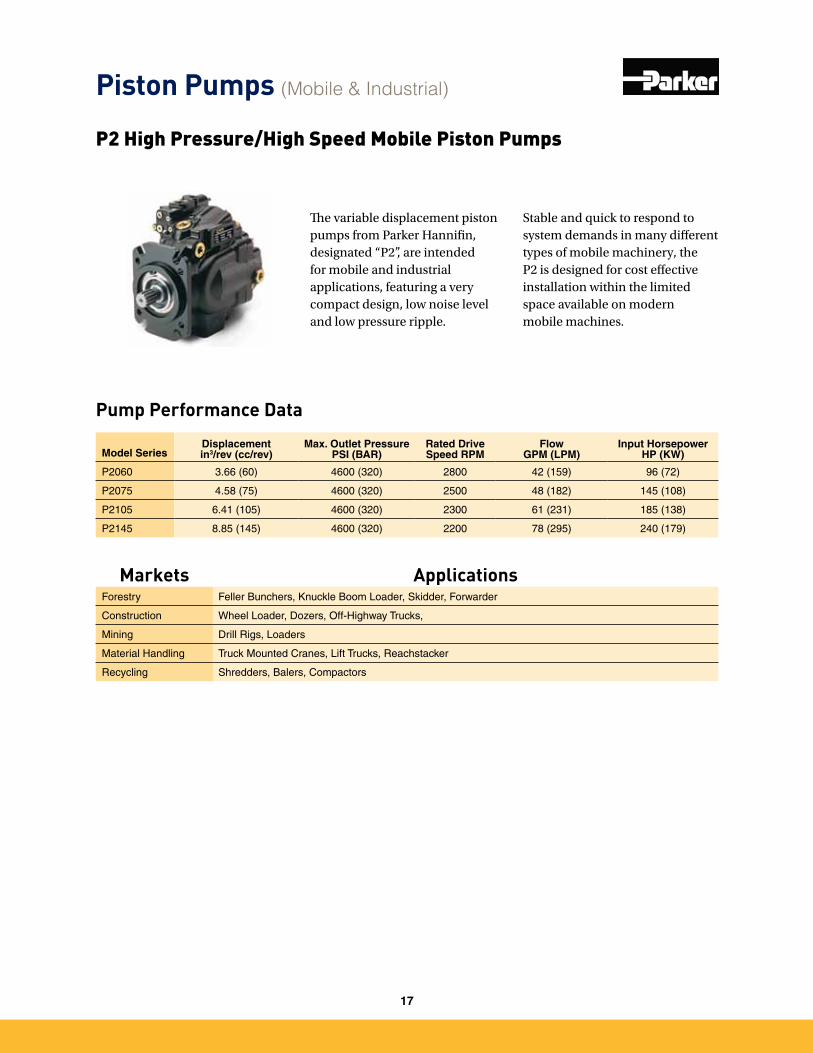
Pump Performance Data
The variable displacement piston pumps from Parker Hannifin, designated “P2”, are intended for mobile and industrial applications, featuring a very compact design, low noise level and low pressure ripple.
Stable and quick to respond to system demands in many different types of mobile machinery, the P2 is designed for cost effective installation within the limited space available on modern mobile machines.
P2 High Pressure/High Speed Mobile Piston Pumps
Model SeriesDisplacementin3/rev (cc/rev)
Max. Outlet PressurePSI (BAR)
Rated Drive Speed RPM
Flow GPM (LPM)
Input Horsepower HP (KW)
P2060 3�66 (60) 4600 (320) 2800 42 (159) 96 (72)
P2075 4�58 (75) 4600 (320) 2500 48 (182) 145 (108)
P2105 6�41 (105) 4600 (320) 2300 61 (231) 185 (138)
P2145 8�85 (145) 4600 (320) 2200 78 (295) 240 (179)
Piston Pumps (Mobile & Industrial)
Markets ApplicationsForestry Feller Bunchers, Knuckle Boom Loader, Skidder, Forwarder
Construction Wheel Loader, Dozers, Off-Highway Trucks,
Mining Drill Rigs, Loaders
Material Handling Truck Mounted Cranes, Lift Trucks, Reachstacker
Recycling Shredders, Balers, Compactors
17
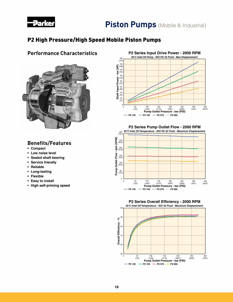
Performance Characteristics
Benefits/Features• Compact• Low noise level• Sealed shaft bearing• Service friendly• Reliable• Long-lasting• Flexible• Easy to install• High self-priming speed
P2 Series Input Drive Power - 2000 RPM40˚C Inlet Oil Temp - ISO VG 32 Fluid - Max Displacement
0 50 (725)
100(1450)
150(2176)
200(2901)
250(3626)
350(5075)
300(4351)
Pump Outlet Pressure - bar (PSI)
Sh
aft
Inp
ut
Po
wer
- k
w (
HP
)
0
20(27)
40(54)
60(80)
80(107)
100(134)
120(161)
140(188)
160(215)
P2 145 P2 105 P2 075 P2 060
50(13.2)
100(26.4)
150(39.6)
200(52.8)
250(66.0)
300(79.3)
00
50 (725)
100(1450)
150(2176)
200(2901)
250(3626)
300(4351)
350(5075)
Pump Outlet Pressure - bar (PSI)
Pu
mp
Ou
tlet
Flo
w -
lpm
(G
PM
)
P2 Series Pump Outlet Flow - 2000 RPM40˚C Inlet Oil Temperature - ISO VG 32 Fluid - Maximum Displacement
P2 145 P2 105 P2 075 P2 060
P2 Series Overall Efficiency - 2000 RPM40˚C Inlet Oil Temperature - ISO 32 Fluid - Maximum Displacement
0 50 (725)
100(1450)
150(2176)
200(2901)
250(3626)
300(4351)
Pump Outlet Pressure - bar (PSI)
Ove
rall
Eff
icie
ncy
- %
50
60
70
80
90
100
P2 145 P2 105 P2 075 P2 060
P2 High Pressure/High Speed Mobile Piston Pumps
Piston Pumps (Mobile & Industrial)
18
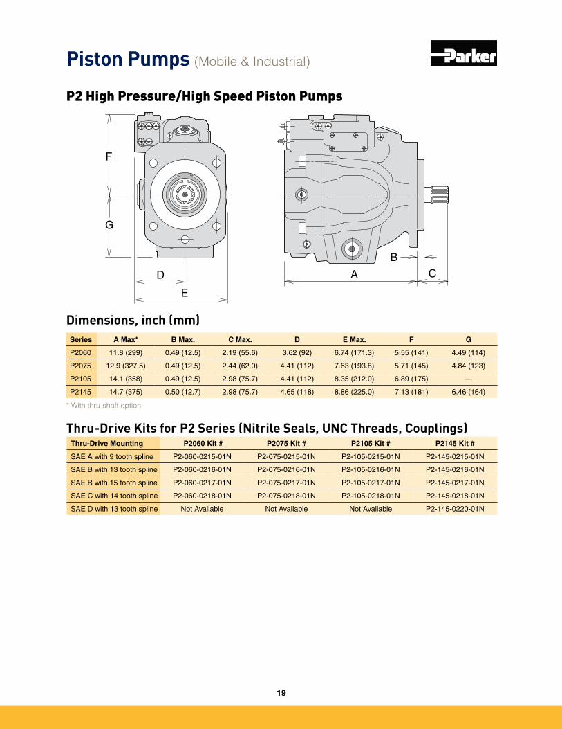
Dimensions, inch (mm)
G
F
D
E
A C
B
Series A Max* B Max. C Max. D E Max. F G
P2060 11�8 (299) 0�49 (12�5) 2�19 (55�6) 3�62 (92) 6�74 (171�3) 5�55 (141) 4�49 (114)
P2075 12�9 (327�5) 0�49 (12�5) 2�44 (62�0) 4�41 (112) 7�63 (193�8) 5�71 (145) 4�84 (123)
P2105 14�1 (358) 0�49 (12�5) 2�98 (75�7) 4�41 (112) 8�35 (212�0) 6�89 (175) —
P2145 14�7 (375) 0�50 (12�7) 2�98 (75�7) 4�65 (118) 8�86 (225�0) 7�13 (181) 6�46 (164)
* With thru-shaft option
Thru-Drive Mounting P2060 Kit # P2075 Kit # P2105 Kit # P2145 Kit #
SAE A with 9 tooth spline P2-060-0215-01N P2-075-0215-01N P2-105-0215-01N P2-145-0215-01N
SAE B with 13 tooth spline P2-060-0216-01N P2-075-0216-01N P2-105-0216-01N P2-145-0216-01N
SAE B with 15 tooth spline P2-060-0217-01N P2-075-0217-01N P2-105-0217-01N P2-145-0217-01N
SAE C with 14 tooth spline P2-060-0218-01N P2-075-0218-01N P2-105-0218-01N P2-145-0218-01N
SAE D with 13 tooth spline Not Available Not Available Not Available P2-145-0220-01N
Thru-Drive Kits for P2 Series (Nitrile Seals, UNC Threads, Couplings)
Piston Pumps (Mobile & Industrial)
P2 High Pressure/High Speed Piston Pumps
19
Percent of Max
Displacement
ShaftOption
Model
Maximum Rated Torque
TA/TB Adj. Range20%-60%
of Max Torque
TC/TD Adj. Range,50%-90%
of Max Torque
Nm lb-in Nm lb-in Nm lb-in
P2060 339 3004 68-204 600-1802 170-306 1502-2703
P2075 424 3755 85-254 751-2253 212-382 1877-3379
P2105 594 5257 119-356 1051-3154 297-535 2628-4731
P2145 820 7259 164-492 1451-4355 410-738 3629-6533
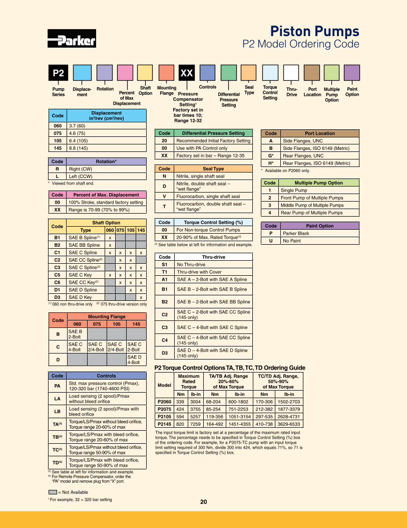
P2 XX
Code Controls
PA Std� max pressure control (Pmax), 120-320 bar (1740-4600 PSI)
LA Load sensing (2 spool)/Pmax without bleed orifice
LB Load sensing (2 spool)/Pmax with bleed orifice
TA(3) Torque/LS/Pmax without bleed orifice, Torque range 20-60% of max
TB(3) Torque/LS/Pmax with bleed orifice, Torque range 20-60% of max
TC(3) Torque/LS/Pmax without bleed orifice, Torque range 50-90% of max
TD(3) Torque/LS/Pmax with bleed orifice, Torque range 50-90% of max
Code Rotation*
R Right (CW)
L Left (CCW)
* Viewed from shaft end�
Code Percent of Max. Displacement
00 100% Stroke, standard factory setting
XX Range is 70-99 (70% to 99%)
Code Displacement in3/rev (cm3/rev)
060 3�7 (60)
075 4�6 (75)
105 6�4 (105)
145 8�8 (145)
Multiple PumpOption
Thru-Drive
Torque Control Setting
Displace-ment
PumpSeries
Port Location
Paint Option
CodeMounting Flange
060 075 105 145
B SAE B 2-Bolt
C SAE C 4-Bolt
SAE C 2/4-Bolt
SAE C 2/4-Bolt
SAE C 2-Bolt
D SAE D4-Bolt
Code Differential Pressure Setting
20 Recommended Initial Factory Setting
00 Use with PA Control only
XX Factory set in bar – Range 12-35
Code Seal Type
N Nitrile, single shaft seal
D Nitrile, double shaft seal – “wet flange”
V Fluorocarbon, single shaft seal
T Fluorocarbon, double shaft seal – “wet flange”
Code Thru-drive
S1 No Thru-drive
T1 Thru-drive with Cover
A1 SAE A – 2-Bolt with SAE A Spline
B1 SAE B – 2-Bolt with SAE B Spline
B2 SAE B – 2-Bolt with SAE BB Spline
C2 SAE C – 2-Bolt with SAE CC Spline (145 only)
C3 SAE C – 4-Bolt with SAE C Spline
C4 SAE C – 4-Bolt with SAE CC Spline (145 only)
D3 SAE D – 4-Bolt with SAE D Spline (145 only)
Code Port Location
A Side Flanges, UNC
B Side Flanges, ISO 6149 (Metric)
G* Rear Flanges, UNC
H* Rear Flanges, ISO 6149 (Metric)
* Available on P2060 only�
Code Multiple Pump Option
1 Single Pump
2 Front Pump of Multiple Pumps
3 Middle Pump of Multiple Pumps
4 Rear Pump of Multiple Pumps
Code Paint Option
P Parker Black
U No Paint
= Not Available
CodeShaft Option
Type 060 075 105 145
B1 SAE B Spline(1) x
B2 SAE BB Spline x
C1 SAE C Spline x x x x
C2 SAE CC Spline(2) x x
C3 SAE C Spline(2) x x x
C5 SAE C Key x x x x
C6 SAE CC Key(2) x x x
D1 SAE D Spline x x
D3 SAE D Key x(1) 060 non thru-drive only (2) 075 thru-drive version only
(3) See table at left for information and example�(4) For Remote Pressure Compensator, order the
“PA” model and remove plug from “X” port�
1 For example, 32 = 320 bar setting
P2 Torque Control Options TA, TB, TC, TD Ordering Guide
The input torque limit is factory set at a percentage of the maximum rated input torque� The percentage needs to be specified in Torque Control Setting (%) box of the ordering code� For example, for a P2075-TC pump with an input torque limit setting required of 300 Nm, divide 300 into 424, which equals 71%, so 71 is specified in Torque Control Setting (%) box�
Code Torque Control Setting (%)
00 For Non-torque Control Pumps
XX 20-90% of Max� Rated Torque(3)
(3) See table below at left for information and example�
Controls
Pressure Compensator
Setting1
Factory set in bar times 10; Range 12-32
Differential Pressure Setting
Piston Pumps P2 Model Ordering Code
Rotation SealType
MountingFlange
20
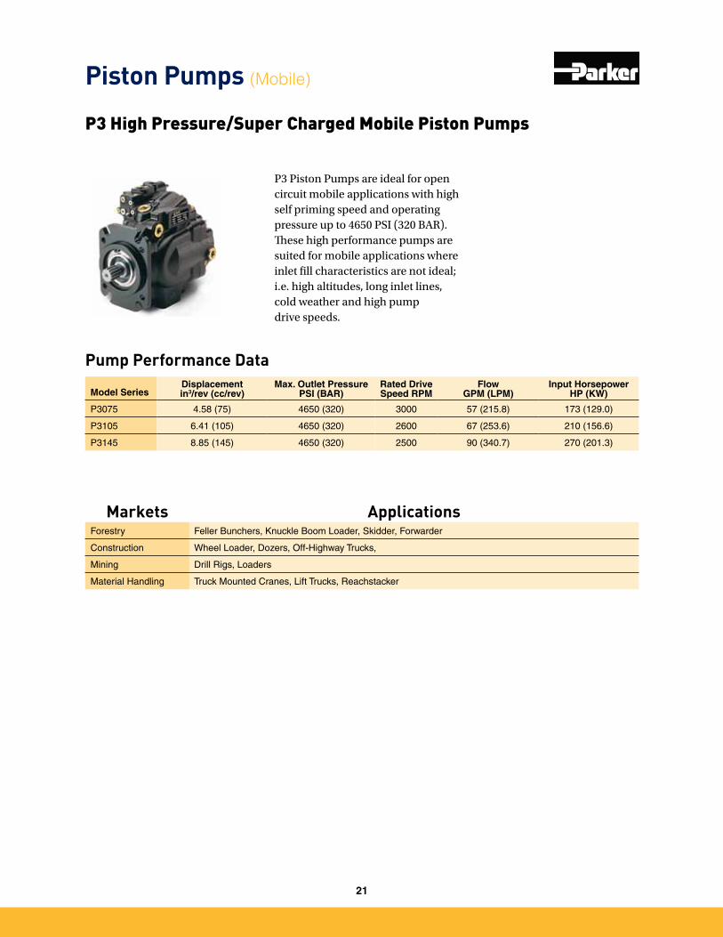
Pump Performance Data
P3 Piston Pumps are ideal for open circuit mobile applications with high self priming speed and operating pressure up to 4650 PSI (320 BAR). These high performance pumps are suited for mobile applications where inlet fill characteristics are not ideal; i.e. high altitudes, long inlet lines, cold weather and high pump drive speeds.
P3 High Pressure/Super Charged Mobile Piston Pumps
Model SeriesDisplacementin3/rev (cc/rev)
Max. Outlet PressurePSI (BAR)
Rated Drive Speed RPM
Flow GPM (LPM)
Input Horsepower HP (KW)
P3075 4�58 (75) 4650 (320) 3000 57 (215�8) 173 (129�0)
P3105 6�41 (105) 4650 (320) 2600 67 (253�6) 210 (156�6)
P3145 8�85 (145) 4650 (320) 2500 90 (340�7) 270 (201�3)
Piston Pumps (Mobile)
Markets ApplicationsForestry Feller Bunchers, Knuckle Boom Loader, Skidder, Forwarder
Construction Wheel Loader, Dozers, Off-Highway Trucks,
Mining Drill Rigs, Loaders
Material Handling Truck Mounted Cranes, Lift Trucks, Reachstacker
21
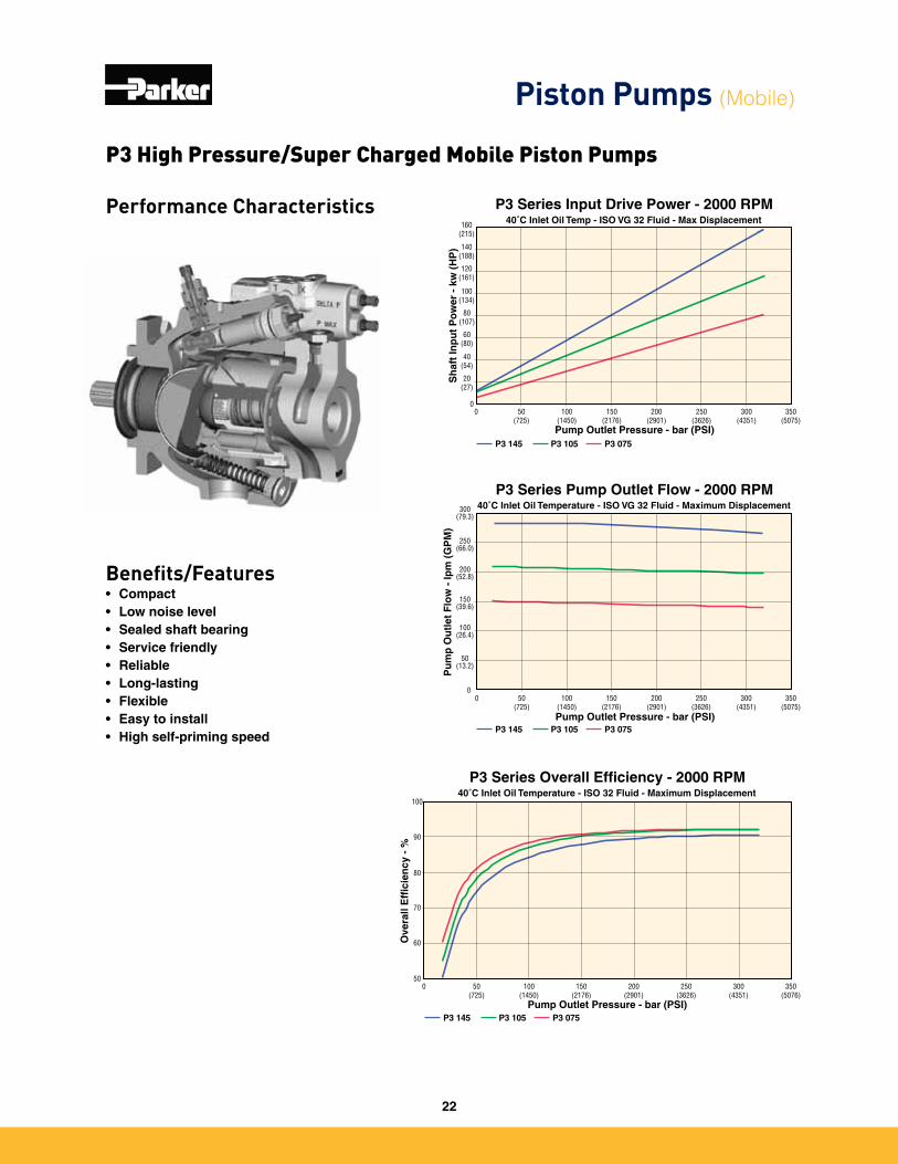
Performance Characteristics
Benefits/Features• Compact• Low noise level• Sealed shaft bearing• Service friendly• Reliable• Long-lasting• Flexible• Easy to install• High self-priming speed
P3 Series Input Drive Power - 2000 RPM40˚C Inlet Oil Temp - ISO VG 32 Fluid - Max Displacement
0 50 (725)
100(1450)
150(2176)
200(2901)
250(3626)
350(5075)
300(4351)
Pump Outlet Pressure - bar (PSI)
Sh
aft
Inp
ut
Po
wer
- k
w (
HP
)
0
20(27)
40(54)
60(80)
80(107)
100(134)
120(161)
140(188)
160(215)
P3 145 P3 105 P3 075
50(13.2)
100(26.4)
150(39.6)
200(52.8)
250(66.0)
300(79.3)
00
50 (725)
100(1450)
150(2176)
200(2901)
250(3626)
300(4351)
350(5075)
Pump Outlet Pressure - bar (PSI)
Pu
mp
Ou
tlet
Flo
w -
lpm
(G
PM
)
P3 Series Pump Outlet Flow - 2000 RPM40˚C Inlet Oil Temperature - ISO VG 32 Fluid - Maximum Displacement
P3 145 P3 105 P3 075
P3 Series Overall Efficiency - 2000 RPM40˚C Inlet Oil Temperature - ISO 32 Fluid - Maximum Displacement
0 50 (725)
100(1450)
150(2176)
200(2901)
250(3626)
300(4351)
350(5076)
Pump Outlet Pressure - bar (PSI)
Ove
rall
Eff
icie
ncy
- %
50
60
70
80
90
100
P3 145 P3 105 P3 075
P3 High Pressure/Super Charged Mobile Piston Pumps
Piston Pumps (Mobile)
22
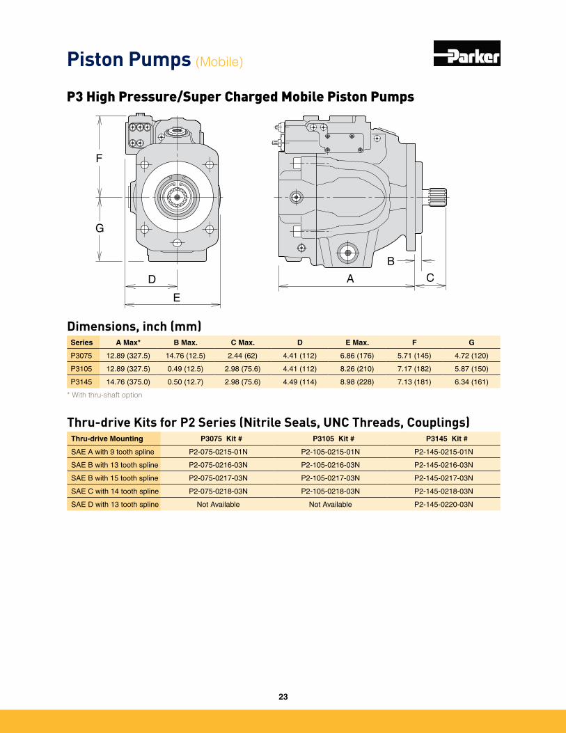
Dimensions, inch (mm)Series A Max* B Max. C Max. D E Max. F G
P3075 12�89 (327�5) 14�76 (12�5) 2�44 (62) 4�41 (112) 6�86 (176) 5�71 (145) 4�72 (120)
P3105 12�89 (327�5) 0�49 (12�5) 2�98 (75�6) 4�41 (112) 8�26 (210) 7�17 (182) 5�87 (150)
P3145 14�76 (375�0) 0�50 (12�7) 2�98 (75�6) 4�49 (114) 8�98 (228) 7�13 (181) 6�34 (161)
G
F
D
E
A C
B
Thru-drive Mounting P3075 Kit # P3105 Kit # P3145 Kit #
SAE A with 9 tooth spline P2-075-0215-01N P2-105-0215-01N P2-145-0215-01N
SAE B with 13 tooth spline P2-075-0216-03N P2-105-0216-03N P2-145-0216-03N
SAE B with 15 tooth spline P2-075-0217-03N P2-105-0217-03N P2-145-0217-03N
SAE C with 14 tooth spline P2-075-0218-03N P2-105-0218-03N P2-145-0218-03N
SAE D with 13 tooth spline Not Available Not Available P2-145-0220-03N
Thru-drive Kits for P2 Series (Nitrile Seals, UNC Threads, Couplings)
* With thru-shaft option
Piston Pumps (Mobile)
P3 High Pressure/Super Charged Mobile Piston Pumps
23
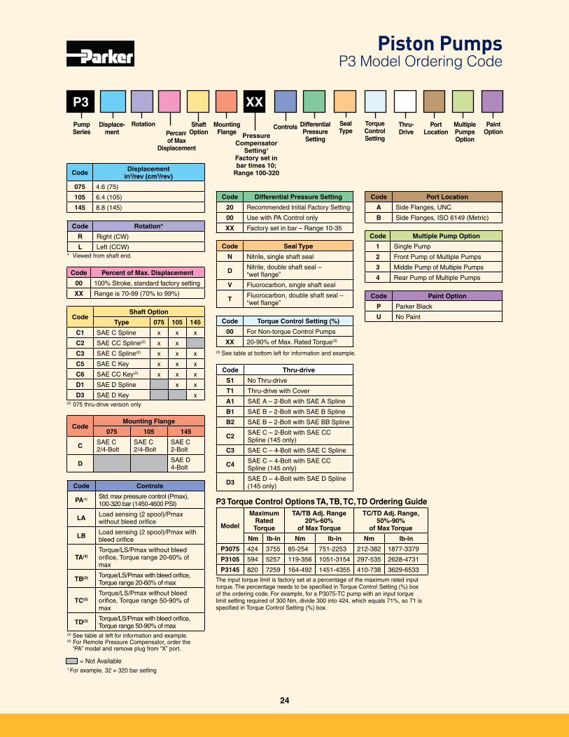
Pressure Compensator
Setting1
Factory set in bar times 10;
Range 100-320
Model
Maximum Rated Torque
TA/TB Adj. Range20%-60%
of Max Torque
TC/TD Adj. Range,50%-90%
of Max Torque
Nm lb-in Nm lb-in Nm lb-in
P3075 424 3755 85-254 751-2253 212-382 1877-3379
P3105 594 5257 119-356 1051-3154 297-535 2628-4731
P3145 820 7259 164-492 1451-4355 410-738 3629-6533
P3
Code Controls
PA(4) Std� max pressure control (Pmax), 100-320 bar (1450-4600 PSI)
LA Load sensing (2 spool)/Pmax without bleed orifice
LB Load sensing (2 spool)/Pmax with bleed orifice
TA(3)Torque/LS/Pmax without bleed orifice, Torque range 20-60% of max
TB(3) Torque/LS/Pmax with bleed orifice, Torque range 20-60% of max
TC(3)Torque/LS/Pmax without bleed orifice, Torque range 50-90% of max
TD(3) Torque/LS/Pmax with bleed orifice, Torque range 50-90% of max
(3) See table at left for information and example�(4) For Remote Pressure Compensator, order the
“PA” model and remove plug from “X” port�
Code Rotation*
R Right (CW)
L Left (CCW)* Viewed from shaft end�
Code Percent of Max. Displacement
00 100% Stroke, standard factory setting
XX Range is 70-99 (70% to 99%)
Code Displacement in3/rev (cm3/rev)
075 4�6 (75)
105 6�4 (105)
145 8�8 (145)
Multiple Pumps Option
Thru-Drive
Torque Control Setting
MountingFlange
Displace-ment
PumpSeries
Port Location
Paint Option
CodeMounting Flange
075 105 145
C SAE C 2/4-Bolt
SAE C 2/4-Bolt
SAE C 2-Bolt
D SAE D4-Bolt
Code Differential Pressure Setting
20 Recommended Initial Factory Setting
00 Use with PA Control only
XX Factory set in bar – Range 10-35
Code Seal Type
N Nitrile, single shaft seal
D Nitrile, double shaft seal – “wet flange”
V Fluorocarbon, single shaft seal
T Fluorocarbon, double shaft seal – “wet flange”
Code Thru-drive
S1 No Thru-drive
T1 Thru-drive with Cover
A1 SAE A – 2-Bolt with SAE A Spline
B1 SAE B – 2-Bolt with SAE B Spline
B2 SAE B – 2-Bolt with SAE BB Spline
C2 SAE C – 2-Bolt with SAE CC Spline (145 only)
C3 SAE C – 4-Bolt with SAE C Spline
C4 SAE C – 4-Bolt with SAE CC Spline (145 only)
D3 SAE D – 4-Bolt with SAE D Spline (145 only)
Code Port Location
A Side Flanges, UNC
B Side Flanges, ISO 6149 (Metric)
Code Multiple Pump Option
1 Single Pump
2 Front Pump of Multiple Pumps
3 Middle Pump of Multiple Pumps
4 Rear Pump of Multiple Pumps
Code Paint Option
P Parker Black
U No Paint
= Not Available
CodeShaft Option
Type 075 105 145
C1 SAE C Spline x x x
C2 SAE CC Spline(2) x x
C3 SAE C Spline(2) x x x
C5 SAE C Key x x x
C6 SAE CC Key(2) x x x
D1 SAE D Spline x x
D3 SAE D Key x(2) 075 thru-drive version only
P3 Torque Control Options TA, TB, TC, TD Ordering Guide
The input torque limit is factory set at a percentage of the maximum rated input torque� The percentage needs to be specified in Torque Control Setting (%) box of the ordering code� For example, for a P3075-TC pump with an input torque limit setting required of 300 Nm, divide 300 into 424, which equals 71%, so 71 is specified in Torque Control Setting (%) box�
Code Torque Control Setting (%)
00 For Non-torque Control Pumps
XX 20-90% of Max� Rated Torque(3)
(3) See table at bottom left for information and example�
Percant of Max
Displacement
Rotation Controls Differential Pressure Setting
Piston Pumps P3 Model Ordering Code
XX
1 For example, 32 = 320 bar setting
ShaftOption
SealType
24
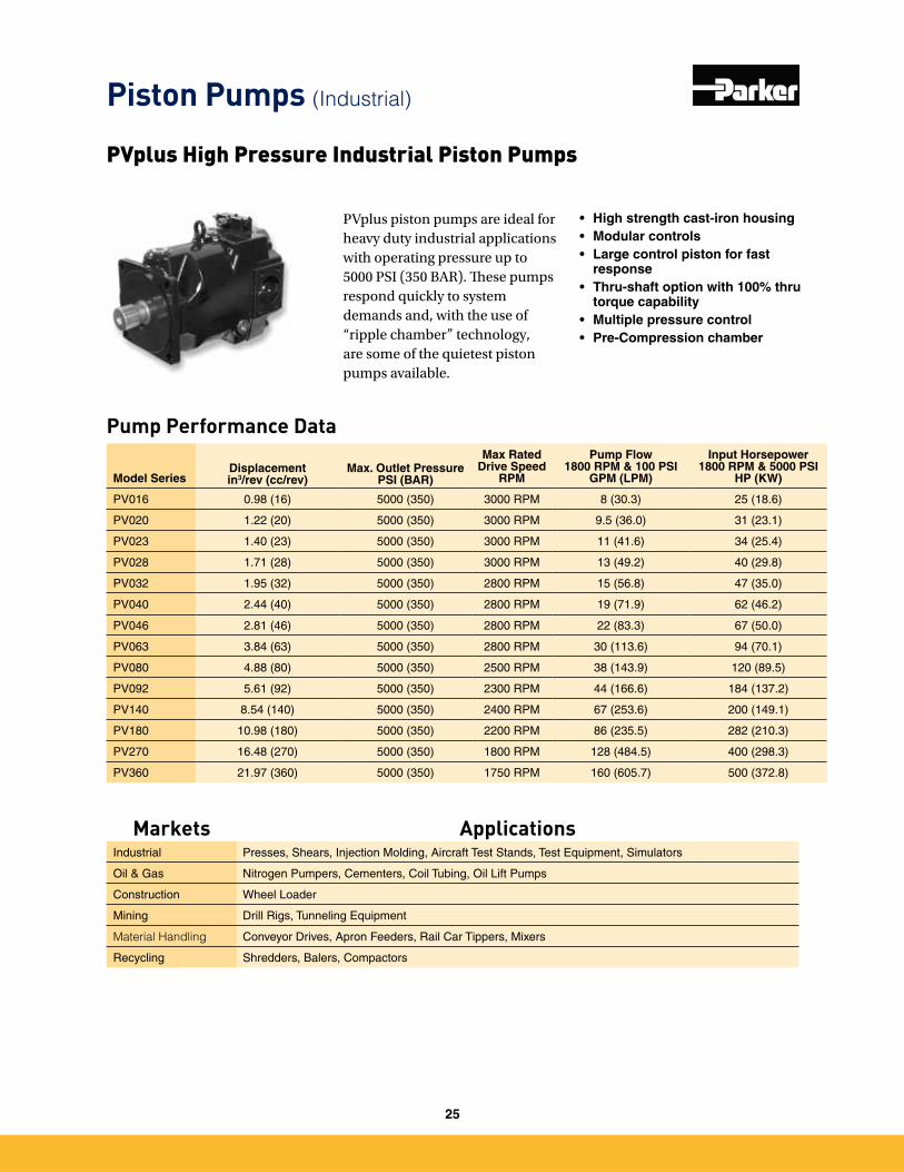
Pump Performance Data
Model SeriesDisplacementin3/rev (cc/rev)
Max. Outlet PressurePSI (BAR)
Max Rated Drive Speed
RPM
Pump Flow 1800 RPM & 100 PSI
GPM (LPM)
Input Horsepower 1800 RPM & 5000 PSI
HP (KW)
PV016 0�98 (16) 5000 (350) 3000 RPM 8 (30�3) 25 (18�6)
PV020 1�22 (20) 5000 (350) 3000 RPM 9�5 (36�0) 31 (23�1)
PV023 1�40 (23) 5000 (350) 3000 RPM 11 (41�6) 34 (25�4)
PV028 1�71 (28) 5000 (350) 3000 RPM 13 (49�2) 40 (29�8)
PV032 1�95 (32) 5000 (350) 2800 RPM 15 (56�8) 47 (35�0)
PV040 2�44 (40) 5000 (350) 2800 RPM 19 (71�9) 62 (46�2)
PV046 2�81 (46) 5000 (350) 2800 RPM 22 (83�3) 67 (50�0)
PV063 3�84 (63) 5000 (350) 2800 RPM 30 (113�6) 94 (70�1)
PV080 4�88 (80) 5000 (350) 2500 RPM 38 (143�9) 120 (89�5)
PV092 5�61 (92) 5000 (350) 2300 RPM 44 (166�6) 184 (137�2)
PV140 8�54 (140) 5000 (350) 2400 RPM 67 (253�6) 200 (149�1)
PV180 10�98 (180) 5000 (350) 2200 RPM 86 (235�5) 282 (210�3)
PV270 16�48 (270) 5000 (350) 1800 RPM 128 (484�5) 400 (298�3)
PV360 21�97 (360) 5000 (350) 1750 RPM 160 (605�7) 500 (372�8)
PVplus piston pumps are ideal for heavy duty industrial applications with operating pressure up to 5000 PSI (350 BAR). These pumps respond quickly to system demands and, with the use of “ripple chamber” technology, are some of the quietest piston pumps available.
• High strength cast-iron housing• Modular controls• Large control piston for fast
response• Thru-shaft option with 100% thru
torque capability• Multiple pressure control• Pre-Compression chamber
PVplus High Pressure Industrial Piston Pumps
Piston Pumps (Industrial)
Markets ApplicationsIndustrial Presses, Shears, Injection Molding, Aircraft Test Stands, Test Equipment, Simulators
Oil & Gas Nitrogen Pumpers, Cementers, Coil Tubing, Oil Lift Pumps
Construction Wheel Loader
Mining Drill Rigs, Tunneling Equipment
Material Handling Conveyor Drives, Apron Feeders, Rail Car Tippers, Mixers
Recycling Shredders, Balers, Compactors
25

PVplus High Pressure Industrial Piston Pumps
Benefits/Features• High strength cast-iron hous-
ing for high reliability and quiet operation
• Modular controls for field con-vertibility
• Large control piston for fast response
• Thru-shaft option with 100% thru torque capability
• Multiple pressure control with valves mounted directly on pump
• Pre-compression chamber to minimize over-all system noise
• High self-priming speed and cold start capability
Piston Pumps (Industrial)
26
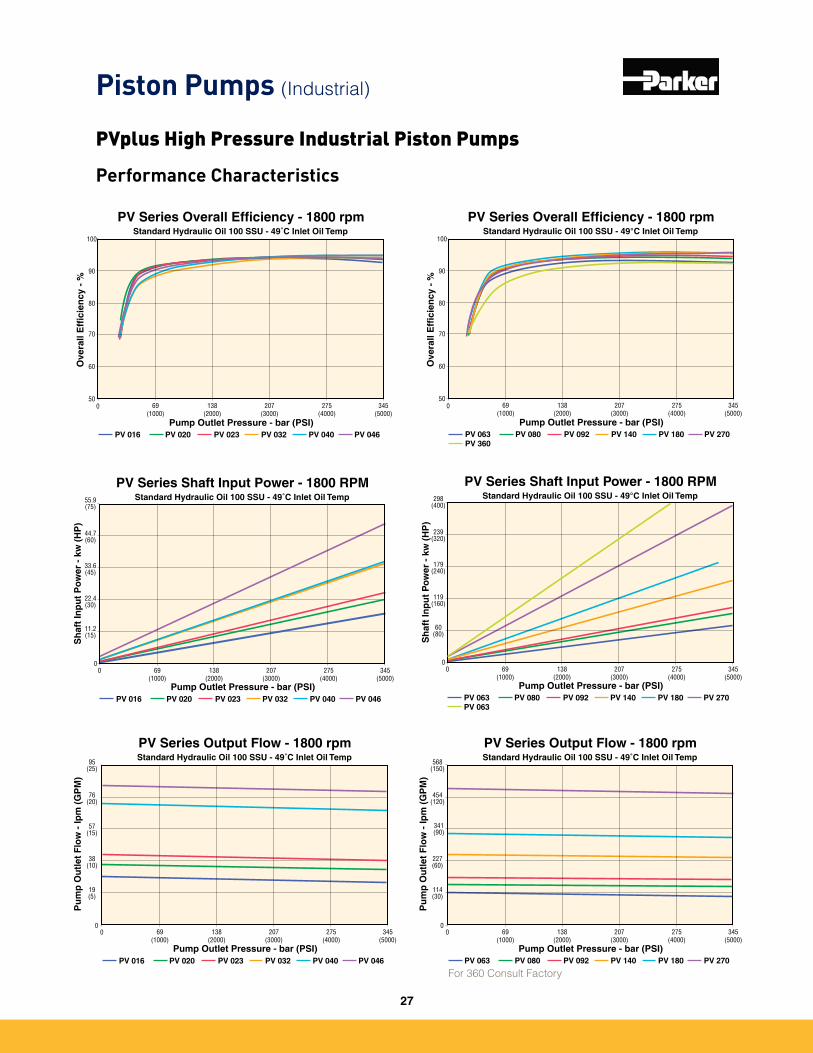
Performance Characteristics
69(1000)
138(2000)
275 (4000)
345 (5000)
207 (3000)
PV Series Overall Efficiency - 1800 rpmStandard Hydraulic Oil 100 SSU - 49˚C Inlet Oil Temp
0
Pump Outlet Pressure - bar (PSI)
Ove
rall
Eff
icie
ncy
- %
50
60
70
80
90
100
PV 016 PV 020 PV 023 PV 032 PV 040 PV 046
69(1000)
138(2000)
275(4000)
345(5000)
207(3000)
PV Series Overall Efficiency - 1800 rpmStandard Hydraulic Oil 100 SSU - 49°C Inlet Oil Temp
0
Pump Outlet Pressure - bar (PSI)O
vera
ll E
ffic
ien
cy -
%
50
60
70
80
90
100
PV 063PV 360
PV 080 PV 092 PV 140 PV 180 PV 270
PV Series Shaft Input Power - 1800 RPMStandard Hydraulic Oil 100 SSU - 49˚C Inlet Oil Temp
0
Pump Outlet Pressure - bar (PSI)
Sh
aft
Inp
ut
Po
wer
- k
w (
HP
)
0
22.4(30)
11.2(15)
33.6 (45)
44.7 (60)
55.9(75)
69(1000)
138(2000)
275 (4000)
345 (5000)
207 (3000)
PV 016 PV 020 PV 023 PV 032 PV 040 PV 046
PV Series Shaft Input Power - 1800 RPMStandard Hydraulic Oil 100 SSU - 49°C Inlet Oil Temp
0
Pump Outlet Pressure - bar (PSI)
Sh
aft
Inp
ut
Po
wer
- k
w (
HP
)
0
119(160)
60(80)
179(240)
239(320)
298(400)
69(1000)
138(2000)
275(4000)
345(5000)
207(3000)
PV 063PV 063
PV 080 PV 092 PV 140 PV 180 PV 270
PV Series Output Flow - 1800 rpmStandard Hydraulic Oil 100 SSU - 49˚C Inlet Oil Temp
00
Pump Outlet Pressure - bar (PSI)
95 (25)
76 (20)
57 (15)
38 (10)
19 (5)
Pu
mp
Ou
tlet
Flo
w -
lpm
(G
PM
)
PV 016 PV 020 PV 023 PV 032 PV 040 PV 046
69(1000)
138(2000)
275 (4000)
345 (5000)
207 (3000)
PV Series Output Flow - 1800 rpmStandard Hydraulic Oil 100 SSU - 49˚C Inlet Oil Temp
00
Pump Outlet Pressure - bar (PSI)
568 (150)
454 (120)
341 (90)
227 (60)
114 (30)
Pu
mp
Ou
tlet
Flo
w -
lpm
(G
PM
)
69(1000)
138(2000)
275 (4000)
345 (5000)
207 (3000)
PV 063 PV 080 PV 092 PV 140 PV 180 PV 270
Piston Pumps (Industrial)
PVplus High Pressure Industrial Piston Pumps
For 360 Consult Factory
27
B
C
Shaft Option "K"
D
F
G
A
A2
E
H
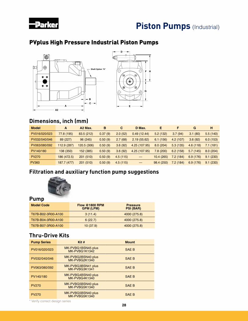
Model A A2 Max. B C D Max. E F G H
PV016/020/023 77�8 (195) 83�5 (212) 0�37 (9) 2�0 (52) 0�49 (12�44) 5�2 (132) 3�7 (94) 3�1 (80) 5�5 (140)
PV032/040/046 89 (227) 96 (245) 0�50 (9) 2�7 (68) 2�19 (55�62) 6�1 (156) 4�2 (107) 3�6 (92) 6�0 (153)
PV063/080/092 112�9 (287) 120�5 (306) 0�50 (9) 3�6 (92) 4�25 (107�95) 8�0 (204) 5�3 (135) 4�6 (118) 7�1 (181)
PV140/180 138 (350) 152 (385) 0�50 (9) 3�6 (92) 4�25 (107�95) 7�8 (200) 6�2 (158) 5�7 (145) 8�0 (204)
PV270 186 (472�5) 201 (510) 0�50 (9) 4�5 (115) — 10�4 (265) 7�2 (184) 6�9 (176) 9�1 (230)
PV360 187�7 (477) 201 (510) 0�50 (9) 4�5 (115) — 98�4 (250) 7�2 (184) 6�9 (176) 9�1 (230)
Dimensions, inch (mm)
Filtration and auxiliary function pump suggestions
Model Code Flow @1800 RPMGPM (LPM)
PressurePSI (BAR)
T67B-B02-3R00-A100 3 (11�4) 4000 (275�8)
T67B-B04-3R00-A100 6 (22�7) 4000 (275�8)
T67B-B07-3R00-A100 10 (37�9) 4000 (275�8)
Pump Series Kit # Mount
PV016/020/023 MK-PVBG1BSN45 plus MK-PVBG1K1342 SAE B
PV032/040/046 MK-PVBG2BSN40 plusMK-PVBG2K1340 SAE B
PV063/080/092 MK-PVBG3BSN41 plusMK-PVBG3K1341 SAE B
PV140/180 MK-PVBG4BSN40 plusMK-PVBG4K1340 SAE B
PV270 MK-PVBG5BSN40 plusMK-PVBG5K1340 SAE B
PV270 MK-PVBG5BSN40 plusMK-PVBG5K1340 SAE B
Pump
Thru-Drive Kits
* Verify correct design series
Piston Pumps (Industrial)
PVplus High Pressure Industrial Piston Pumps
28
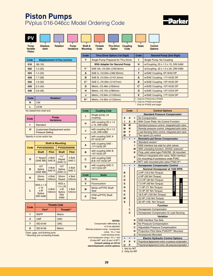
PV
Code Pump Variations
1 Standard
9* Customized Displacement and/or Pressure Setting
*Specify in cc/rev and/or bar�
Code Rotation*
R CW
L CCW
Code Displacement in3/rev (cc/rev)
016 �98 (16)
020 1�2 (20)
023 1�4 (23)
028 1�7 (28)
032 1�9 (32)
040 2�4 (40)
046 2�8 (46)
Code Coupling Code
1 Single pump, no coupling
H with coupling 25 x 1�5 x 15, DIN 5480
J with coupling 32 x 1�5 x 20, DIN 5480
Y with coupling SAE A 9T-16/32 DP
A with coupling SAE - 11T-16/32 DP
B with coupling SAE B 13T-16/32 DP
C with coupling SAE B-B 15T-16/32 DP
D with coupling SAE C 14T-12/24 DP
Code Seals
N Nitrile
V Fluorocarbon
W Nitrile w/PTFE Shaft Seal
P FPM w/PTFE Shaft Seal
Pump VariablePiston
Displace- ment
Rotation PumpVariations
Shaft & Mounting
Threads Code
Code
Shaft & Mounting
PV016/020/023 PV032/040/046
Shaft Pilot Shaft Pilot
D 1" Keyed (SAE BB)
4 Bolt SAE B
1¼" Keyed
(SAE C)
4 Bolt SAE C
E15T
Spline (SAE BB)
4 Bolt SAE B
14T Spline
(SAE C)
4 Bolt SAE C
K 25mm Keyed
4 Bolt 100mm
32mm Keyed
4 Bolt 125mm
L
W25 x 1�5 x 15 x 8f
Spline DIN 5480
4-Bolt 100mm
W32 x 1�5 x 20
x 8f Spline DIN 5480
4 Bolt 125mm
Code Control Options
Standard Pressure Compensator
0 0 1 No Compensator
1 0 0 With Cover Plate, No Control FunctionM M Standard pressure control, integrated pilot valveM R Remote pressure control, integrated pilot valveM F Load Sensing (flow) control, integrated pilot valveM T Two spool LS control• • • Remote/Load Sense Compensator
C Standard version 1
1 NG6 interface top side for pilot valvesW With unloading function, 24VDC solenoid 1
K Prop�-pilot valve type PVACRE��35 mounted
Z Without integrated pilot valve, NG6 interface,for mounting of accessory code PVAC
P MT1 with mounted pilot valve PVAC1P 2
• • • Horsepower Compensator Control
Nominal Horsepower at 1500 RPM
B 3 HP (19�5 Nm Torque)
C 4 HP (26 Nm Torque)
D 5�5 HP (36 Nm Torque)
E 7�5 HP (49 Nm Torque)
G 11 HP (71 Nm Torque)
H 15 HP (97 Nm Torque)
K 18�5 HP (120 Nm Torque)
M 22 HP (142 Nm Torque)
S 30 HP (195 Nm Torque)
Function
L Horsepower Compensator
C Horsepower Compensator & Load Sensing
Variation
A NG6 Interface Top Side
B No Pressure Compensation
C Adjustable Pressure Compensation
D Proportion Pilot Valve PVACPP* Mounted
Z Accessories Mounted• • • Electro Hydraulic Control OptionsF P V Proportional displacement control, no pressure compensationU P Proportional displacement control, with pressurecompensation
1 Not for MT2 Only for MT
NOTES:Compensator differential Dp
is to be adjusted: Remote pressure comp�, horsepower
comp� 15 ± 1 bar Load-sensing comp�
(not horsepower comp�) 10 ± 1 bar (Codes MF* and LS part of MT*)
Consult catalog on CD for electrohydraulic control options.
PV
016/
020/
023
PV
032/
040/
046
*As viewed from shaft end�
CouplingCode
Piston Pumps PVplus 016-046cc Model Ordering Code
Code Thru-Drive Option (1st Digit)
T Single Pump Prepared for Thru-Drive
With Adapter for Second Pump
Y 1 SAE AA, ∅2�00in (∅50�8mm)
A SAE A, ∅3�25in (∅82�55mm)
B SAE B, ∅4�00in (∅101�6mm)
C 2 SAE C, ∅5�00in (∅127mm)
G Metric, ∅2�48in (∅63mm)
H Metric, ∅3�15in (∅80mm)
J Metric, ∅3�94in (∅100mm)
K 2 Metric, ∅4�92in (∅125mm)
Code Second Pump (2nd Digit)
1 Single Pump, No Coupling
H w/Coupling, 25 x 1�5 x 15, DIN 5480
J w/Coupling, 32 x 1�5 x 20, DIN 5480
Y w/SAE Coupling, 9T-16/32 DP
A w/SAE Coupling, 11T-16/32 DP
B w/SAE Coupling, 13T-16/32 DP
C* w/SAE Coupling, 15T-16/32 DP
D w/SAE Coupling, 14T-12/24 DP
E w/SAE Coupling, 17T-12/24 DP
1 Only for PV016 thru PV0232 Only for PV032 and larger * Only for PV032 and larger
Thru-Drive Option
CodeThreads Code
Port* Threads**
1 BSPP Metric
3 UNF UNC
7 ISO 6149 UNC
8 ISO 6149 Metric
*Drain, gage, and flushing ports�** Mounting and connecting threads
Control Options
Seals
29
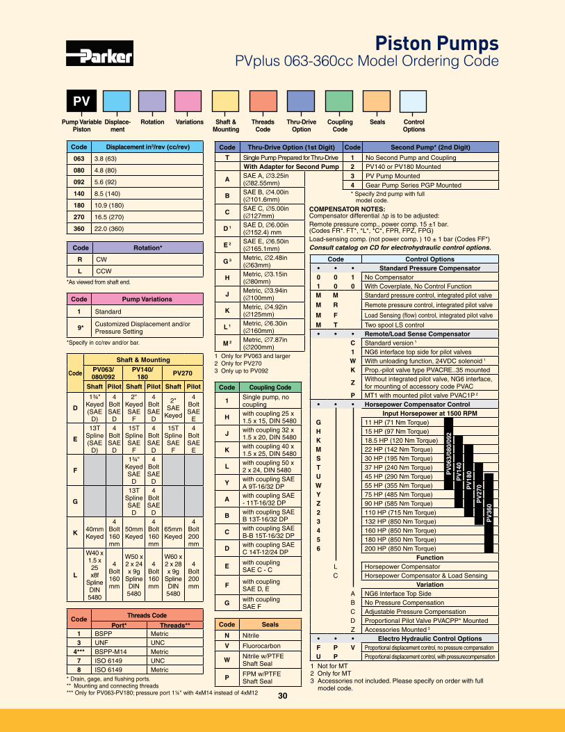
Code Thru-Drive Option (1st Digit)
T Single Pump Prepared for Thru-DriveWith Adapter for Second Pump
A SAE A, ∅3�25in (∅82�55mm)
B SAE B, ∅4�00in (∅101�6mm)
C SAE C, ∅5�00in(∅127mm)
D 1 SAE D, ∅6�00in(∅152�4) mm
E 2 SAE E, ∅6�50in (∅165�1mm)
G 3 Metric, ∅2�48in(∅63mm)
H Metric, ∅3�15in(∅80mm)
J Metric, ∅3�94in(∅100mm)
K Metric, ∅4�92in(∅125mm)
L 1 Metric, ∅6�30in(∅160mm)
M 2 Metric, ∅7�87in (∅200mm)
Code Control Options• • • Standard Pressure Compensator0 0 1 No Compensator1 0 0 With Coverplate, No Control FunctionM M Standard pressure control, integrated pilot valve
M R Remote pressure control, integrated pilot valve
M F Load Sensing (flow) control, integrated pilot valve
M T Two spool LS control• • • Remote/Load Sense Compensator
C Standard version 1
1 NG6 interface top side for pilot valvesW With unloading function, 24VDC solenoid 1
K Prop�-pilot valve type PVACRE��35 mounted
Z Without integrated pilot valve, NG6 interface,for mounting of accessory code PVAC
P MT1 with mounted pilot valve PVAC1P 2
• • • Horsepower Compensator ControlInput Horsepower at 1500 RPM
G 11 HP (71 Nm Torque)H 15 HP (97 Nm Torque)K 18�5 HP (120 Nm Torque)M 22 HP (142 Nm Torque)S 30 HP (195 Nm Torque)T 37 HP (240 Nm Torque)U 45 HP (290 Nm Torque)W 55 HP (355 Nm Torque)Y 75 HP (485 Nm Torque)Z 90 HP (585 Nm Torque)2 110 HP (715 Nm Torque)3 132 HP (850 Nm Torque)4 160 HP (850 Nm Torque)5 180 HP (850 Nm Torque)6 200 HP (850 Nm Torque)
FunctionL Horsepower CompensatorC Horsepower Compensator & Load Sensing
VariationA NG6 Interface Top SideB No Pressure CompensationC Adjustable Pressure CompensationD Proportional Pilot Valve PVACPP* MountedZ Accessories Mounted 3
• • • Electro Hydraulic Control OptionsF P V Proportional displacement control, no pressure compensationU P Proportional displacement control, with pressurecompensation
1 Not for MT2 Only for MT3 Accessories not included� Please specify on order with full
model code�
Code Coupling Code
1 Single pump, no coupling
H with coupling 25 x 1�5 x 15, DIN 5480
J with coupling 32 x 1�5 x 20, DIN 5480
K with coupling 40 x 1�5 x 25, DIN 5480
L with coupling 50 x 2 x 24, DIN 5480
Y with coupling SAE A 9T-16/32 DP
A with coupling SAE - 11T-16/32 DP
B with coupling SAE B 13T-16/32 DP
C with coupling SAE B-B 15T-16/32 DP
D with coupling SAE C 14T-12/24 DP
E with coupling SAE C - C
F with coupling SAE D, E
G with coupling SAE F
PV
Code Pump Variations
1 Standard
9* Customized Displacement and/or Pressure Setting
*Specify in cc/rev and/or bar�
Code Rotation*
R CW
L CCW
Code Displacement in3/rev (cc/rev)
063 3�8 (63)
080 4�8 (80)
092 5�6 (92)
140 8�5 (140)
180 10�9 (180)
270 16�5 (270)
360 22�0 (360)
Pump Variable Piston
Displace- ment
Rotation Variations Shaft & Mounting
Threads Code
CouplingCode
Code Threads Code
Port* Threads**1 BSPP Metric3 UNF UNC
4*** BSPP-M14 Metric7 ISO 6149 UNC8 ISO 6149 Metric
* Drain, gage, and flushing ports�** Mounting and connecting threads*** Only for PV063-PV180; pressure port 1¼" with 4xM14 instead of 4xM12
Code
Shaft & Mounting
PV063/080/092
PV140/180 PV270
Shaft Pilot Shaft Pilot Shaft Pilot
D
1¾" Keyed (SAE
D)
4 BoltSAE
D
2" Keyed SAE
F
4 Bolt SAE
D
2" SAE
Keyed
4 Bolt SAE
E
E
13T Spline (SAE
D)
4 Bolt SAE
D
15T Spline SAE
F
4 Bolt SAE
D
15T Spline SAE
F
4 Bolt SAE
E
F
1¾" Keyed SAE
D
4 Bolt SAE
D
G
13T Spline SAE
D
4 Bolt SAE
D
K 40mm Keyed
4 Bolt160mm
50mm Keyed
4 Bolt 160mm
65mm Keyed
4 Bolt 200mm
L
W40 x 1�5 x 25 x8f
Spline DIN 5480
4 Bolt160mm
W50 x 2 x 24 x 9g
Spline DIN 5480
4 Bolt 160mm
W60 x 2 x 28 x 9g
Spline DIN 5480
4 Bolt 200mm
PV
140
PV
180
PV
270
PV
360
*As viewed from shaft end�
Code Second Pump* (2nd Digit)
1 No Second Pump and Coupling2 PV140 or PV180 Mounted3 PV Pump Mounted4 Gear Pump Series PGP Mounted
* Specify 2nd pump with full model code�
PV
063/
080/
092
COMPENSATOR NOTES:Compensator differential Dp is to be adjusted:Remote pressure comp�, power comp� 15 ±1 bar� (Codes FR*� FT*, *L*, *C*, FPR, FPZ, FPG)Load-sensing comp� (not power comp� ) 10 ± 1 bar (Codes FF*)Consult catalog on CD for electrohydraulic control options.
Piston Pumps PVplus 063-360cc Model Ordering Code
1 Only for PV063 and larger2 Only for PV270 3 Only up to PV092
Thru-Drive Option
Seals Control Options
Code Seals
N Nitrile
V Fluorocarbon
W Nitrile w/PTFE Shaft Seal
P FPM w/PTFE Shaft Seal
30
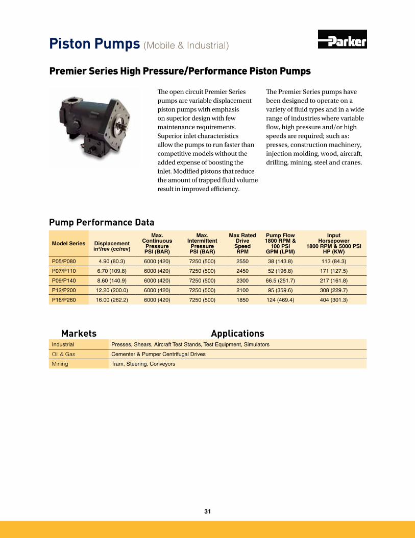
Pump Performance Data
Model Series
Displacementin3/rev (cc/rev)
Max. Continuous
PressurePSI (BAR)
Max. Intermittent
PressurePSI (BAR)
Max Rated DriveSpeedRPM
Pump Flow 1800 RPM &
100 PSIGPM (LPM)
Input Horsepower
1800 RPM & 5000 PSIHP (KW)
P05/P080 4�90 (80�3) 6000 (420) 7250 (500) 2550 38 (143�8) 113 (84�3)
P07/P110 6�70 (109�8) 6000 (420) 7250 (500) 2450 52 (196�8) 171 (127�5)
P09/P140 8�60 (140�9) 6000 (420) 7250 (500) 2300 66�5 (251�7) 217 (161�8)
P12/P200 12�20 (200�0) 6000 (420) 7250 (500) 2100 95 (359�6) 308 (229�7)
P16/P260 16�00 (262�2) 6000 (420) 7250 (500) 1850 124 (469�4) 404 (301�3)
The open circuit Premier Series pumps are variable displacement piston pumps with emphasis on superior design with few maintenance requirements. Superior inlet characteristics allow the pumps to run faster than competitive models without the added expense of boosting the inlet. Modified pistons that reduce the amount of trapped fluid volume result in improved efficiency.
The Premier Series pumps have been designed to operate on a variety of fluid types and in a wide range of industries where variable flow, high pressure and/or high speeds are required; such as: presses, construction machinery, injection molding, wood, aircraft, drilling, mining, steel and cranes.
Premier Series High Pressure/Performance Piston Pumps
Piston Pumps (Mobile & Industrial)
Markets ApplicationsIndustrial Presses, Shears, Aircraft Test Stands, Test Equipment, Simulators
Oil & Gas Cementer & Pumper Centrifugal Drives
Mining Tram, Steering, Conveyors
31
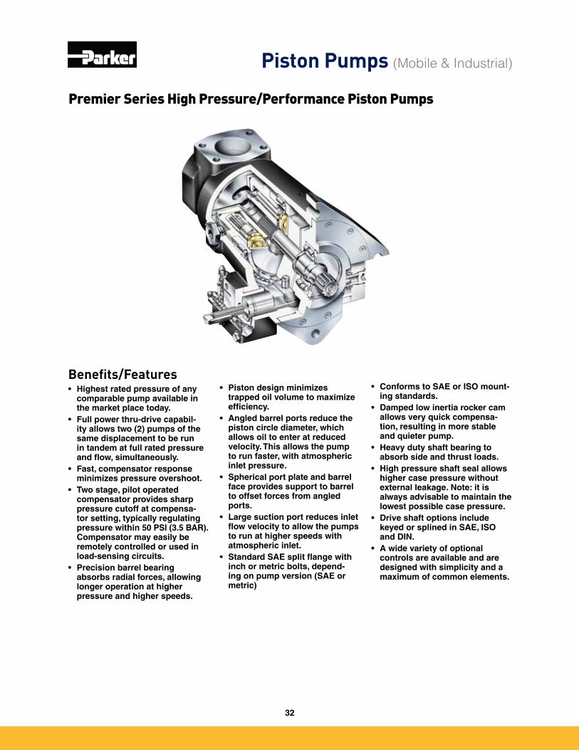
Benefits/Features• Highest rated pressure of any
comparable pump available in the market place today.
• Full power thru-drive capabil-ity allows two (2) pumps of the same displacement to be run in tandem at full rated pressure and flow, simultaneously.
• Fast, compensator response minimizes pressure overshoot.
• Two stage, pilot operated compensator provides sharp pressure cutoff at compensa-tor setting, typically regulating pressure within 50 PSI (3.5 BAR). Compensator may easily be remotely controlled or used in load-sensing circuits.
• Precision barrel bearing absorbs radial forces, allowing longer operation at higher pressure and higher speeds.
• Piston design minimizes trapped oil volume to maximize efficiency.
• Angled barrel ports reduce the piston circle diameter, which allows oil to enter at reduced velocity. This allows the pump to run faster, with atmospheric inlet pressure.
• Spherical port plate and barrel face provides support to barrel to offset forces from angled ports.
• Large suction port reduces inlet flow velocity to allow the pumps to run at higher speeds with atmospheric inlet.
• Standard SAE split flange with inch or metric bolts, depend-ing on pump version (SAE or metric)
Premier Series High Pressure/Performance Piston Pumps
• Conforms to SAE or ISO mount-ing standards.
• Damped low inertia rocker cam allows very quick compensa-tion, resulting in more stable and quieter pump.
• Heavy duty shaft bearing to absorb side and thrust loads.
• High pressure shaft seal allows higher case pressure without external leakage. Note: it is always advisable to maintain the lowest possible case pressure.
• Drive shaft options include keyed or splined in SAE, ISO and DIN.
• A wide variety of optional controls are available and are designed with simplicity and a maximum of common elements.
Piston Pumps (Mobile & Industrial)
32
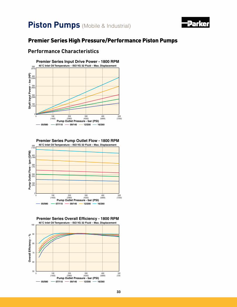
Premier Series Input Drive Power - 1800 RPM40˚C Inlet Oil Temperature – ISO VG 32 Fluid – Max. Displacement
0
Pump Outlet Pressure - bar (PSI)
Sh
aft
Inp
ut
Po
wer
– k
w (
HP
)
0
200(268)
100(134)
300 (402)
400 (536)
500(670)
100(1450)
200(2900)
400 (5800)
500(7250)
300 (4350)
05/080 07/110 09/140 12/200 16/260
Premier Series Pump Outlet Flow - 1800 RPM40˚C Inlet Oil Temperature – ISO VG 32 Fluid – Max. Displacement
0
Pump Outlet Pressure - bar (PSI)
Pu
mp
Ou
tlet
Flo
w -
lpm
(G
PM
)
0
200(53)
100(26)
300 (79)
400 (106)
500(132)
100(1450)
200(2900)
400 (5800)
500(7250)
300 (4350)
05/080 07/110 09/140 12/200 16/260
Premier Series Overall Efficiency - 1800 RPM40˚C Inlet Oil Temperature – ISO VG 32 Fluid – Max. Displacement
0
Pump Outlet Pressure - bar (PSI)
Ove
rall
Eff
icie
ncy
– %
50
70
60
80
90
100
100(1450)
200(2900)
400 (5800)
500(7250)
300 (4350)
05/080 07/110 09/140 12/200 16/260
Piston Pumps (Mobile & Industrial)
Premier Series High Pressure/Performance Piston Pumps
Performance Characteristics
33
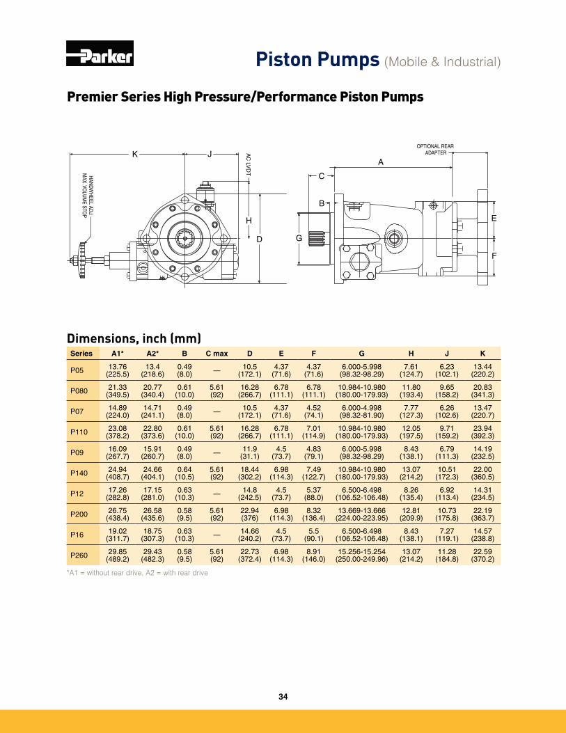
Dimensions, inch (mm)Series A1* A2* B C max D E F G H J K
P05 13�76(225�5)
13�4(218�6)
0�49(8�0) — 10�5
(172�1)4�37
(71�6)4�37
(71�6)6�000-5�998
(98�32-98�29)7�61
(124�7)6�23
(102�1)13�44
(220�2)
P080 21�33(349�5)
20�77(340�4)
0�61(10�0)
5�61(92)
16�28(266�7)
6�78(111�1)
6�78(111�1)
10�984-10�980(180�00-179�93)
11�80(193�4)
9�65(158�2)
20�83(341�3)
P07 14�89(224�0)
14�71(241�1)
0�49(8�0) — 10�5
(172�1)4�37
(71�6)4�52
(74�1)6�000-4�998
(98�32-81�90)7�77
(127�3)6�26
(102�6)13�47
(220�7)
P110 23�08(378�2)
22�80(373�6)
0�61(10�0)
5�61(92)
16�28(266�7)
6�78(111�1)
7�01(114�9)
10�984-10�980(180�00-179�93)
12�05(197�5)
9�71(159�2)
23�94(392�3)
P09 16�09(267�7)
15�91(260�7)
0�49(8�0) — 11�9
(31�1)4�5
(73�7)4�83
(79�1)6�000-5�998
(98�32-98�29)8�43
(138�1)6�79
(111�3)14�19
(232�5)
P140 24�94(408�7)
24�66(404�1)
0�64(10�5)
5�61(92)
18�44(302�2)
6�98(114�3)
7�49(122�7)
10�984-10�980(180�00-179�93)
13�07(214�2)
10�51(172�3)
22�00(360�5)
P12 17�26(282�8)
17�15(281�0)
0�63(10�3) — 14�8
(242�5)4�5
(73�7)5�37
(88�0)6�500-6�498
(106�52-106�48)8�26
(135�4)6�92
(113�4)14�31
(234�5)
P200 26�75(438�4)
26�58(435�6)
0�58(9�5)
5�61(92)
22�94(376)
6�98(114�3)
8�32(136�4)
13�669-13�666(224�00-223�95)
12�81(209�9)
10�73(175�8)
22�19(363�7)
P16 19�02(311�7)
18�75(307�3)
0�63(10�3) — 14�66
(240�2)4�5
(73�7)5�5
(90�1)6�500-6�498
(106�52-106�48)8�43
(138�1)7�27
(119�1)14�57
(238�8)
P260 29�85(489�2)
29�43(482�3)
0�58(9�5)
5�61(92)
22�73(372�4)
6�98(114�3)
8�91(146�0)
15�256-15�254(250�00-249�96)
13�07(214�2)
11�28(184�8)
22�59(370�2)
*A1 = without rear drive, A2 = with rear drive
A
E
F
B
C
G
H
D
JK AC
LVD
T
OPTIONAL REAR ADAPTER
HAN
DWH
EEL ADJ.
MAX. VO
LUM
E STOP
Piston Pumps (Mobile & Industrial)
Premier Series High Pressure/Performance Piston Pumps
34
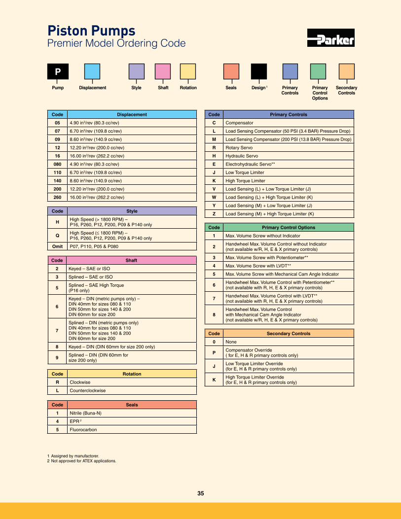
Code Shaft
2 Keyed – SAE or ISO
3 Splined – SAE or ISO
5 Splined – SAE High Torque (P16 only)
6
Keyed – DIN (metric pumps only) –DIN 40mm for sizes 080 & 110DIN 50mm for sizes 140 & 200DIN 60mm for size 200
7
Splined – DIN (metric pumps only)DIN 40mm for sizes 080 & 110DIN 50mm for sizes 140 & 200DIN 60mm for size 200
8 Keyed – DIN (DIN 60mm for size 200 only)
9 Splined – DIN (DIN 60mm for size 200 only)
P
Code Displacement
05 4�90 in3/rev (80�3 cc/rev)
07 6�70 in3/rev (109�8 cc/rev)
09 8�60 in3/rev (140�9 cc/rev)
12 12�20 in3/rev (200�0 cc/rev)
16 16�00 in3/rev (262�2 cc/rev)
080 4�90 in3/rev (80�3 cc/rev)
110 6�70 in3/rev (109�8 cc/rev)
140 8�60 in3/rev (140�9 cc/rev)
200 12�20 in3/rev (200�0 cc/rev)
260 16�00 in3/rev (262�2 cc/rev)
Pump
Code Style
H High Speed (> 1800 RPM) – P16, P260, P12, P200, P09 & P140 only
Q High Speed (≤ 1800 RPM) – P16, P260, P12, P200, P09 & P140 only
Omit P07, P110, P05 & P080
Displacement
Code Rotation
R Clockwise
L Counterclockwise
Code Seals
1 Nitrile (Buna-N)
4 EPR 2
5 Fluorocarbon
Design 1
Code Primary Controls
C Compensator
L Load Sensing Compensator (50 PSI (3�4 BAR) Pressure Drop)
M Load Sensing Compensator (200 PSI (13�8 BAR) Pressure Drop)
R Rotary Servo
H Hydraulic Servo
E Electrohydraulic Servo**
J Low Torque Limiter
K High Torque Limiter
V Load Sensing (L) + Low Torque Limiter (J)
W Load Sensing (L) + High Torque Limiter (K)
Y Load Sensing (M) + Low Torque Limiter (J)
Z Load Sensing (M) + High Torque Limiter (K)
Code Primary Control Options
1 Max� Volume Screw without Indicator
2 Handwheel Max� Volume Control without Indicator (not available w/R, H, E & X primary controls)
3 Max� Volume Screw with Potentiometer**
4 Max� Volume Screw with LVDT**
5 Max� Volume Screw with Mechanical Cam Angle Indicator
6 Handwheel Max� Volume Control with Petentiometer**(not available with R, H, E & X primary controls)
7 Handwheel Max� Volume Control with LVDT**(not available with R, H, E & X primary controls)
8Handwheel Max� Volume Control with Mechanical Cam Angle Indicator (not available w/R, H, E & X primary controls)
Code Secondary Controls
0 None
P Compensator Override ( for E, H & R primary controls only)
J Low Torque Limiter Override (for E, H & R primary controls only)
K High Torque Limiter Override (for E, H & R primary controls only)
Style Shaft Rotation Seals Primary Controls
Primary Control Options
Secondary Controls
1 Assigned by manufactorer�2 Not approved for ATEX applications�
Piston Pumps Premier Model Ordering Code
35
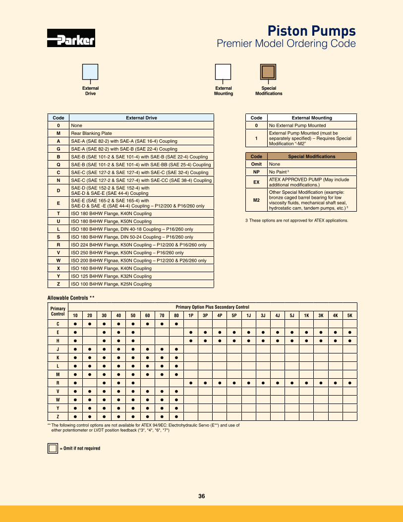
= Omit if not required
Code External Drive
0 None
M Rear Blanking Plate
A SAE-A (SAE 82-2) with SAE-A (SAE 16-4) Coupling
G SAE-A (SAE 82-2) with SAE-B (SAE 22-4) Coupling
B SAE-B (SAE 101-2 & SAE 101-4) with SAE-B (SAE 22-4) Coupling
Q SAE-B (SAE 101-2 & SAE 101-4) with SAE-BB (SAE 25-4) Coupling
C SAE-C (SAE 127-2 & SAE 127-4) with SAE-C (SAE 32-4) Coupling
N SAE-C (SAE 127-2 & SAE 127-4) with SAE-CC (SAE 38-4) Coupling
D SAE-D (SAE 152-2 & SAE 152-4) with SAE-D & SAE-E (SAE 44-4) Coupling
E SAE-E (SAE 165-2 & SAE 165-4) with SAE-D & SAE -E (SAE 44-4) Coupling – P12/200 & P16/260 only
T ISO 180 B4HW Flange, K40N Coupling
U ISO 180 B4HW Flange, K50N Coupling
L ISO 180 B4HW Flange, DIN 40-18 Coupling – P16/260 only
S ISO 180 B4HW Flange, DIN 50-24 Coupling – P16/260 only
R ISO 224 B4HW Flange, K50N Coupling – P12/200 & P16/260 only
V ISO 250 B4HW Flange, K50N Coupling – P16/260 only
W ISO 200 B4HW Flgnae, K50N Coupling – P12/200 & P26/260 only
X ISO 160 B4HW Flange, K40N Coupling
Y ISO 125 B4HW Flange, K32N Coupling
Z ISO 100 B4HW Flange, K25N Coupling
Code External Mounting
0 No External Pump Mounted
1External Pump Mounted (must be separately specified) – Requires Special Modification “-M2”
Code Special Modifications
Omit None
NP No Paint 3
EX ATEX APPROVED PUMP (May include additional modifications�)
M2
Other Special Modification (example: bronze caged barrel bearing for low viscosity fluids, mechanical shaft seal, hydrostatic cam, tandem pumps, etc�) 3
External Mounting
Special Modifications
Allowable Controls **
PrimaryControl
Primary Option Plus Secondary Control
10 20 30 40 50 60 70 80 1P 3P 4P 5P 1J 3J 4J 5J 1K 3K 4K 5K
C l l l l l l l l
E l l l l l l l l l l l l l l l l
H l l l l l l l l l l l l l l l l
J l l l l l l l l
K l l l l l l l l
L l l l l l l l l
M l l l l l l l l
R l l l l l l l l l l l l l l l l
V l l l l l l l l
W l l l l l l l l
Y l l l l l l l l
Z l l l l l l l l
** The following control options are not available for ATEX 94/9EC: Electrohydraulic Servo (E**) and use of either potentiometer or LVDT position feedback (*3*, *4*, *6*, *7*)
ExternalDrive
3 These options are not approved for ATEX applications�
Piston Pumps Premier Model Ordering Code
36
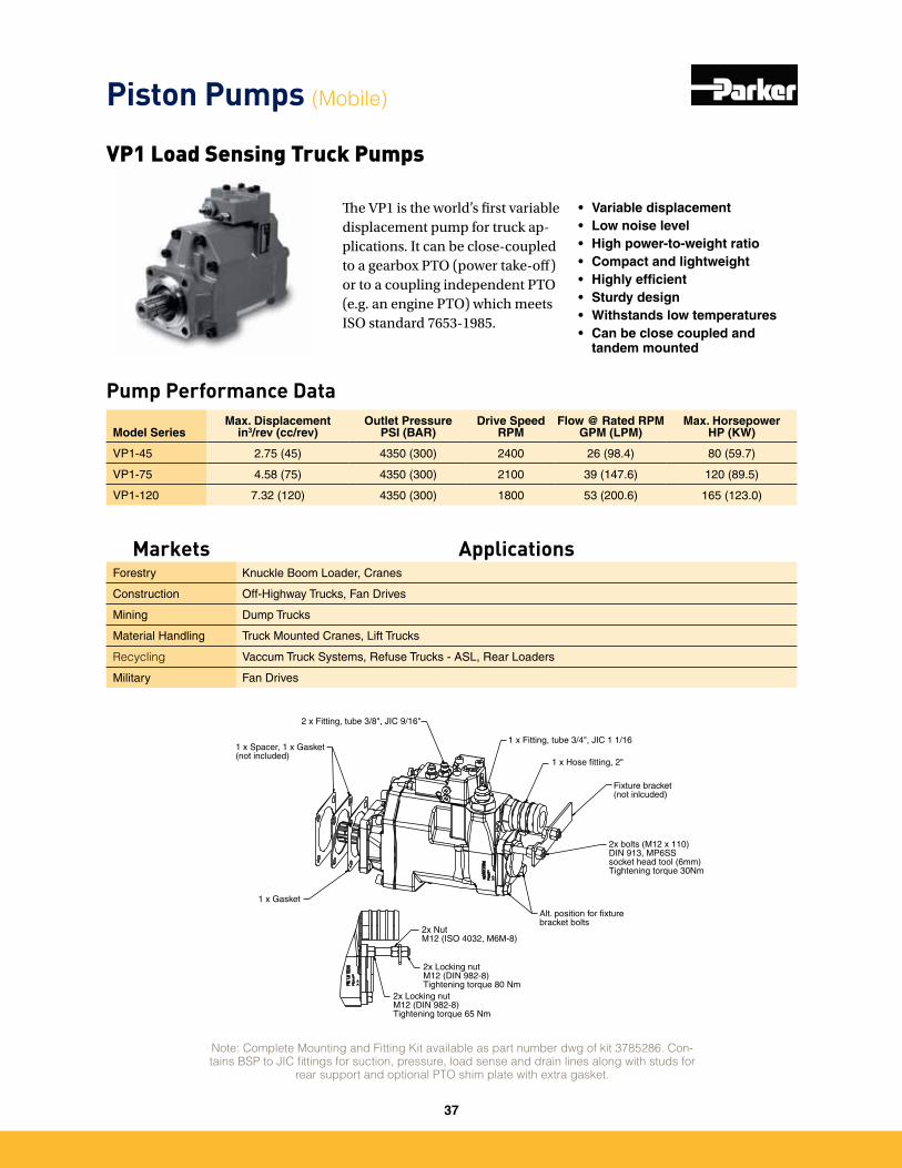
The VP1 is the world’s first variable displacement pump for truck ap-plications. It can be close-coupled to a gearbox PTO (power take-off) or to a coupling independent PTO (e.g. an engine PTO) which meets ISO standard 7653-1985.
• Variable displacement• Low noise level• High power-to-weight ratio• Compact and lightweight• Highly efficient• Sturdy design• Withstands low temperatures• Can be close coupled and
tandem mounted
Pump Performance Data
VP1 Load Sensing Truck Pumps
Model SeriesMax. Displacement
in3/rev (cc/rev)Outlet Pressure
PSI (BAR)Drive Speed
RPMFlow @ Rated RPM
GPM (LPM)Max. Horsepower
HP (KW)
VP1-45 2�75 (45) 4350 (300) 2400 26 (98�4) 80 (59�7)
VP1-75 4�58 (75) 4350 (300) 2100 39 (147�6) 120 (89�5)
VP1-120 7�32 (120) 4350 (300) 1800 53 (200�6) 165 (123�0)
Note: Complete Mounting and Fitting Kit available as part number dwg of kit 3785286. Con-tains BSP to JIC fittings for suction, pressure, load sense and drain lines along with studs for
rear support and optional PTO shim plate with extra gasket.
1 x Fitting, tube 3/4", JIC 1 1/16
1 x Hose fitting, 2"
Fixture bracket(not inlcuded)
2x bolts (M12 x 110)DIN 913, MP6SSsocket head tool (6mm)Tightening torque 30Nm
Alt. position for fixturebracket bolts
2x NutM12 (ISO 4032, M6M-8)
2x Locking nutM12 (DIN 982-8)Tightening torque 80 Nm
2x Locking nutM12 (DIN 982-8)Tightening torque 65 Nm
1 x Gasket
1 x Spacer, 1 x Gasket(not included)
2 x Fitting, tube 3/8", JIC 9/16"
Piston Pumps (Mobile)
Markets ApplicationsForestry Knuckle Boom Loader, Cranes
Construction Off-Highway Trucks, Fan Drives
Mining Dump Trucks
Material Handling Truck Mounted Cranes, Lift Trucks
Recycling Vaccum Truck Systems, Refuse Trucks - ASL, Rear Loaders
Military Fan Drives
37
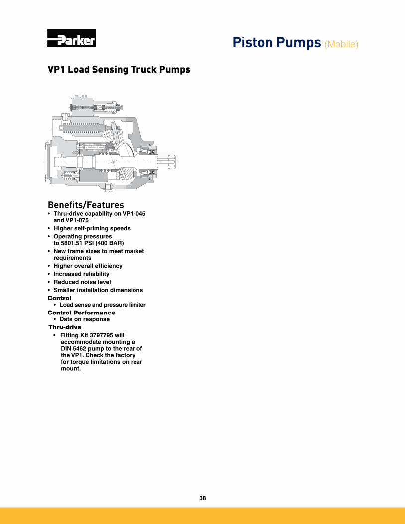
Benefits/Features• Thru-drive capability on VP1-045
and VP1-075• Higher self-priming speeds• Operating pressures
to 5801.51 PSI (400 BAR)• New frame sizes to meet market
requirements• Higher overall efficiency• Increased reliability• Reduced noise level• Smaller installation dimensionsControl
• Load sense and pressure limiterControl Performance
• Data on responseThru-drive • Fitting Kit 3797795 will
accommodate mounting a DIN 5462 pump to the rear of the VP1. Check the factory for torque limitations on rear mount.
VP1 Load Sensing Truck Pumps
Piston Pumps (Mobile)
38
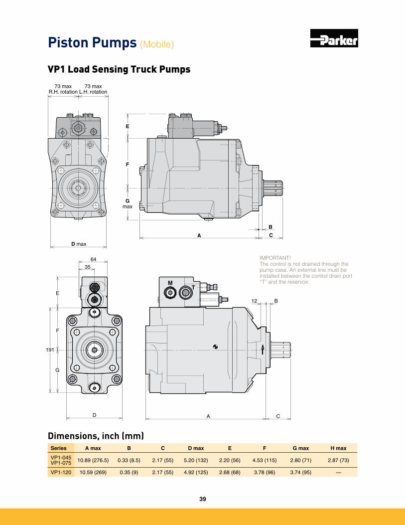
Dimensions, inch (mm)Series A max B C D max E F G max H max
VP1-045 VP1-075 10�89 (276�5) 0�33 (8�5) 2�17 (55) 5�20 (132) 2�20 (56) 4�53 (115) 2�80 (71) 2�87 (73)
VP1-120 10�59 (269) 0�35 (9) 2�17 (55) 4�92 (125) 2�68 (68) 3�78 (96) 3�74 (95) —
A C
B
D max
F
Gmax
E
73 maxR.H. rotation
73 maxL.H. rotation
191
F
G
64
35
D A C
E
B12
MT IMPORTANT!
The control is not drained through the pump case. An external line must be installed between the control drain port “T” and the reservoir.
IMPORTANT!The control is not drained through the pump case. An external line must be installed between the control drain port “T” and the reservoir.
Piston Pumps (Mobile)
VP1 Load Sensing Truck Pumps
39
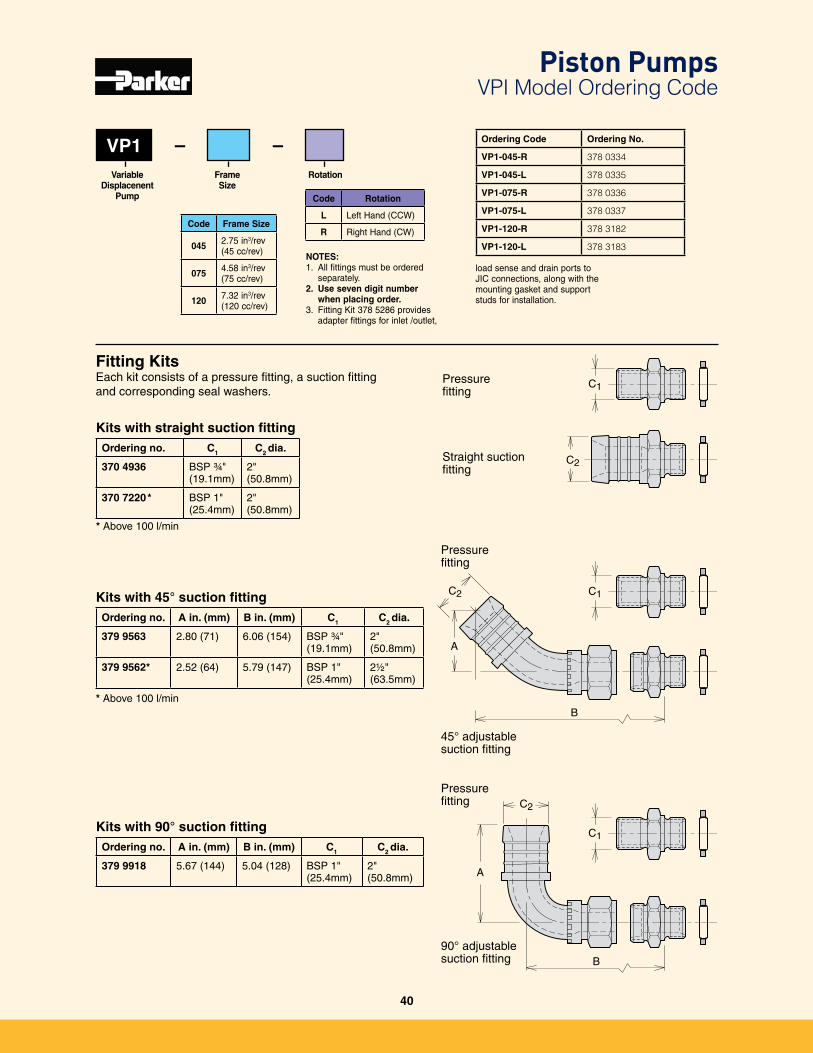
VP1
Code Frame Size
045 2�75 in3/rev(45 cc/rev)
075 4�58 in3/rev(75 cc/rev)
120 7�32 in3/rev(120 cc/rev)
Frame Size
Variable Displacenent
Pump
Rotation
– – Ordering Code Ordering No.
VP1-045-R 378 0334
VP1-045-L 378 0335
VP1-075-R 378 0336
VP1-075-L 378 0337
VP1-120-R 378 3182
VP1-120-L 378 3183
Kits with 90° suction fittingOrdering no. A in. (mm) B in. (mm) C1 C2 dia.
379 9918 5�67 (144) 5�04 (128) BSP 1"(25�4mm)
2"(50�8mm)
Kits with straight suction fittingOrdering no. C1 C2 dia.
370 4936 BSP ¾" (19�1mm)
2"(50�8mm)
370 7220* BSP 1"(25�4mm)
2"(50�8mm)
* Above 100 l/min
Kits with 45° suction fittingOrdering no. A in. (mm) B in. (mm) C1 C2 dia.
379 9563 2�80 (71) 6�06 (154) BSP ¾"(19�1mm)
2"(50�8mm)
379 9562* 2�52 (64) 5�79 (147) BSP 1"(25�4mm)
2½"(63�5mm)
* Above 100 l/min
Fitting KitsEach kit consists of a pressure fitting, a suction fitting and corresponding seal washers�
C2
C2
C2
C1
C1
C1
Fittings_install_GB.epsLeif A./020115
A
B
A
B
Pressure fitting
Straight suction fitting
Pressure fitting
45° adjustable suction fitting
Pressure fitting
90° adjustable suction fitting
NOTES: 1� All fittings must be ordered
separately�2. Use seven digit number
when placing order.3� Fitting Kit 378 5286 provides
adapter fittings for inlet /outlet,
Code Rotation
L Left Hand (CCW)
R Right Hand (CW)
load sense and drain ports to JIC connections, along with the mounting gasket and support studs for installation�
Piston Pumps VPI Model Ordering Code
40
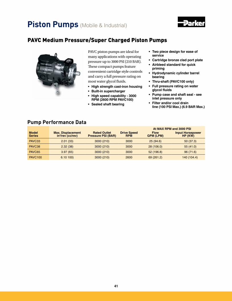
PAVC piston pumps are ideal for many applications with operating pressure up to 3000 PSI (210 BAR). These compact pumps feature convenient cartridge style controls and carry a full pressure rating on most water glycol fluids.• High strength cast-iron housing• Built-in supercharger• High speed capability - 3000
RPM (2600 RPM PAVC100)• Sealed shaft bearing
At MAX RPM and 3000 PSIModel Series
Max. Displacementin3/rev (cc/rev)
Rated Outlet Pressure PSI (BAR)
Drive SpeedRPM
Flow GPM (LPM)
Input Horsepower HP (KW)
PAVC33 2�01 (33) 3000 (210) 3000 25 (94�6) 50 (37�3)
PAVC38 2�32 (38) 3000 (210) 3000 28 (106�0) 55 (41�0)
PAVC65 3�97 (65) 3000 (210) 3000 52 (196�8) 96 (71�6)
PAVC100 6�10 100) 3000 (210) 2600 69 (261�2) 140 (104�4)
Pump Performance Data
• Two piece design for ease of service
• Cartridge bronze clad port plate• Airbleed standard for quick
priming• Hydrodynamic cylinder barrel
bearing• Thru-shaft (PAVC100 only)• Full pressure rating on water
glycol fluids• Pump case and shaft seal - see
inlet pressure only• Filter and/or cool drain
line (100 PSI Max.) (6.9 BAR Max.)
PAVC Medium Pressure/Super Charged Piston Pumps
Piston Pumps (Mobile & Industrial)
41
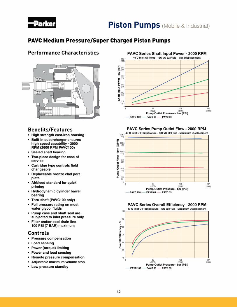
Performance Characteristics
Benefits/Features• High strength cast-iron housing• Built-in supercharger ensures
high speed capability - 3000 RPM (2600 RPM PAVC100)
• Sealed shaft bearing• Two-piece design for ease of
service• Cartridge type controls field
changeable• Replaceable bronze clad port
plate• Airbleed standard for quick
priming• Hydrodynamic cylinder barrel
bearing• Thru-shaft (PAVC100 only)• Full pressure rating on most
water glycol fluids• Pump case and shaft seal are
subjected to inlet pressure only• Filter and/or cool drain line
100 PSI (7 BAR) maximum
Controls• Pressure compensation• Load sensing• Power (torque) limiting• Power and load sensing• Remote pressure compensation• Adjustable maximum volume stop• Low pressure standby
PAVC Series Overall Efficiency - 2000 RPM49˚C Inlet Oil Temperature - ISO 32 Fluid - Maximum Displacement
0 69(1000)
138(2000)
207 (3000)
Pump Outlet Pressure - bar (PSI)
Ove
rall
Eff
icie
ncy
- %
40
50
60
70
80
90
100
PAVC 100 PAVC 65 PAVC 33
PAVC Series Shaft Input Power - 2000 RPM49˚C Inlet Oil Temp - ISO VG 32 Fluid - Max Displacement
0
Pump Outlet Pressure - bar (PSI)
Sh
aft
Inp
ut
Po
wer
- k
w (
HP
)PAVC 100
0
7.5(10 )
22.4(30)
37.3(50)
52.2 (70)
67.1(90)
82.0(110)
PAVC 65 PAVC 33
69(1000)
138(2000)
207 (3000)
0
18.9(5)
56.8 (15)
94.6(25)
132.5(35)
170.3 (45)
208.2(55)
0 69(1000)
138(2000)
207(3000)
Pump Outlet Pressure - bar (PSI)
Pu
mp
Ou
tlet
Flo
w -
lpm
(G
PM
)
PAVC Series Pump Outlet Flow - 2000 RPM 49˚C Inlet Oil Temperature - ISO VG 32 Fluid - Maximum Displacement
PAVC 100 PAVC 65 PAVC 33
PAVC Medium Pressure/Super Charged Piston Pumps
Piston Pumps (Mobile & Industrial)
42
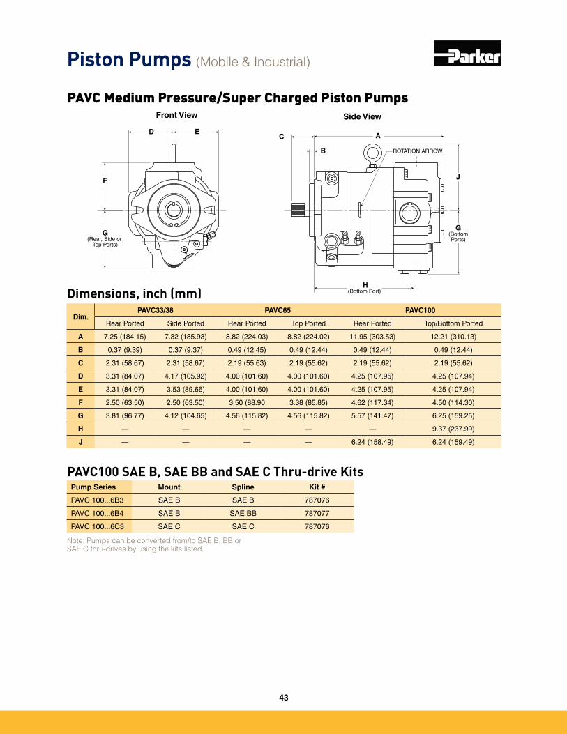
Dim.PAVC33/38 PAVC65 PAVC100
Rear Ported Side Ported Rear Ported Top Ported Rear Ported Top/Bottom Ported
A 7�25 (184�15) 7�32 (185�93) 8�82 (224�03) 8�82 (224�02) 11�95 (303�53) 12�21 (310�13)
B 0�37 (9�39) 0�37 (9�37) 0�49 (12�45) 0�49 (12�44) 0�49 (12�44) 0�49 (12�44)
C 2�31 (58�67) 2�31 (58�67) 2�19 (55�63) 2�19 (55�62) 2�19 (55�62) 2�19 (55�62)
D 3�31 (84�07) 4�17 (105�92) 4�00 (101�60) 4�00 (101�60) 4�25 (107�95) 4�25 (107�94)
E 3�31 (84�07) 3�53 (89�66) 4�00 (101�60) 4�00 (101�60) 4�25 (107�95) 4�25 (107�94)
F 2�50 (63�50) 2�50 (63�50) 3�50 (88�90 3�38 (85�85) 4�62 (117�34) 4�50 (114�30)
G 3�81 (96�77) 4�12 (104�65) 4�56 (115�82) 4�56 (115�82) 5�57 (141�47) 6�25 (159�25)
H — — — — — 9�37 (237�99)
J — — — — 6�24 (158�49) 6�24 (159�49)
Dimensions, inch (mm)
ROTATION ARROW
C
B
J
H(Bottom Port)
AD E
F
G(Rear, Side or
Top Ports)
Side ViewFront View
G(BottomPorts)
Pump Series Mount Spline Kit #
PAVC 100���6B3 SAE B SAE B 787076
PAVC 100���6B4 SAE B SAE BB 787077
PAVC 100���6C3 SAE C SAE C 787076
PAVC100 SAE B, SAE BB and SAE C Thru-drive Kits
Note: Pumps can be converted from/to SAE B, BB or SAE C thru-drives by using the kits listed.
Piston Pumps (Mobile & Industrial)
PAVC Medium Pressure/Super Charged Piston Pumps
43
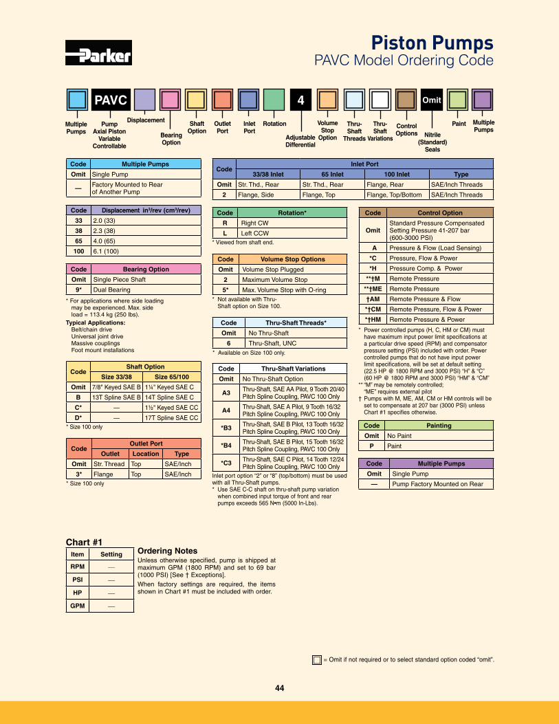
= Omit if not required or to select standard option coded “omit”�
Nitrile(Standard)
Seals
PAVC
Ordering NotesUnless otherwise specified, pump is shipped at maximum GPM (1800 RPM) and set to 69 bar (1000 PSI) [See † Exceptions]�
When factory settings are required, the items shown in Chart #1 must be included with order�
Omit4
Code Thru-Shaft Variations
Omit No Thru-Shaft Option
A3 Thru-Shaft, SAE AA Pilot, 9 Tooth 20/40 Pitch Spline Coupling, PAVC 100 Only
A4 Thru-Shaft, SAE A Pilot, 9 Tooth 16/32 Pitch Spline Coupling, PAVC 100 Only
*B3 Thru-Shaft, SAE B Pilot, 13 Tooth 16/32 Pitch Spline Coupling, PAVC 100 Only
*B4 Thru-Shaft, SAE B Pilot, 15 Tooth 16/32 Pitch Spline Coupling, PAVC 100 Only
*C3 Thru-Shaft, SAE C Pilot, 14 Tooth 12/24 Pitch Spline Coupling, PAVC 100 Only
Inlet port option “2” or “8” (top/bottom) must be used with all Thru-Shaft pumps�* Use SAE C-C shaft on thru-shaft pump variation
when combined input torque of front and rear pumps exceeds 565 N•m (5000 In-Lbs).
Code Rotation*
R Right CW
L Left CCW* Viewed from shaft end�
* For applications where side loading may be experienced� Max� side load = 113�4 kg (250 lbs)�
Typical Applications: Belt/chain drive Universal joint drive Massive couplings Foot mount installations
Code Control Option
OmitStandard Pressure Compensated Setting Pressure 41-207 bar (600-3000 PSI)
A Pressure & Flow (Load Sensing)
*C Pressure, Flow & Power
*H Pressure Comp� & Power
**†M Remote Pressure
**†ME Remote Pressure
†AM Remote Pressure & Flow
*†CM Remote Pressure, Flow & Power
*†HM Remote Pressure & Power
Code Multiple Pumps
Omit Single Pump
— Factory Mounted to Rear of Another Pump
Code Displacement in3/rev (cm3/rev)
33 2�0 (33)
38 2�3 (38)
65 4�0 (65)
100 6�1 (100)
Code Bearing Option
Omit Single Piece Shaft
9* Dual Bearing
* Size 100 only
CodeInlet Port
33/38 Inlet 65 Inlet 100 Inlet Type
Omit Str� Thd�, Rear Str� Thd�, Rear Flange, Rear SAE/Inch Threads
2 Flange, Side Flange, Top Flange, Top/Bottom SAE/Inch Threads
CodeOutlet Port
Outlet Location Type
Omit Str� Thread Top SAE/Inch
3* Flange Top SAE/Inch
Item Setting
RPM —
PSI —
HP —
GPM —
Chart #1
CodeShaft Option
Size 33/38 Size 65/100
Omit 7/8" Keyed SAE B 1¼" Keyed SAE C
B 13T Spline SAE B 14T Spline SAE C
C* — 1½" Keyed SAE CC
D* — 17T Spline SAE CC* Size 100 only
Code Volume Stop Options
Omit Volume Stop Plugged
2 Maximum Volume Stop
5* Max� Volume Stop with O-ring* Not available with Thru-
Shaft option on Size 100�
Code Thru-Shaft Threads*
Omit No Thru-Shaft
6 Thru-Shaft, UNC
* Available on Size 100 only�
Code Painting
Omit No Paint
P Paint
Code Multiple Pumps
Omit Single Pump
— Pump Factory Mounted on Rear
* Power controlled pumps (H, C, HM or CM) must have maximum input power limit specifications at a particular drive speed (RPM) and compensator pressure setting (PSI) included with order� Power controlled pumps that do not have input power limit specifications, will be set at default setting (22�5 HP @ 1800 RPM and 3000 PSI) “H” & “C” (60 HP @ 1800 RPM and 3000 PSI) “HM” & “CM”
** “M” may be remotely controlled; “ME” requires external pilot
† Pumps with M, ME, AM, CM or HM controls will be set to compensate at 207 bar (3000 PSI) unless Chart #1 specifies otherwise�
Multiple Pumps
PaintThru- Shaft
Variations
ControlOptions
Thru-Shaft
Threads
Volume Stop
OptionAdjustableDifferential
RotationInletPort
OutletPort
ShaftOption
Multiple Pumps
DisplacementPump
Axial PistonVariable
Controllable
Bearing Option
Piston Pumps PAVC Model Ordering Code
44
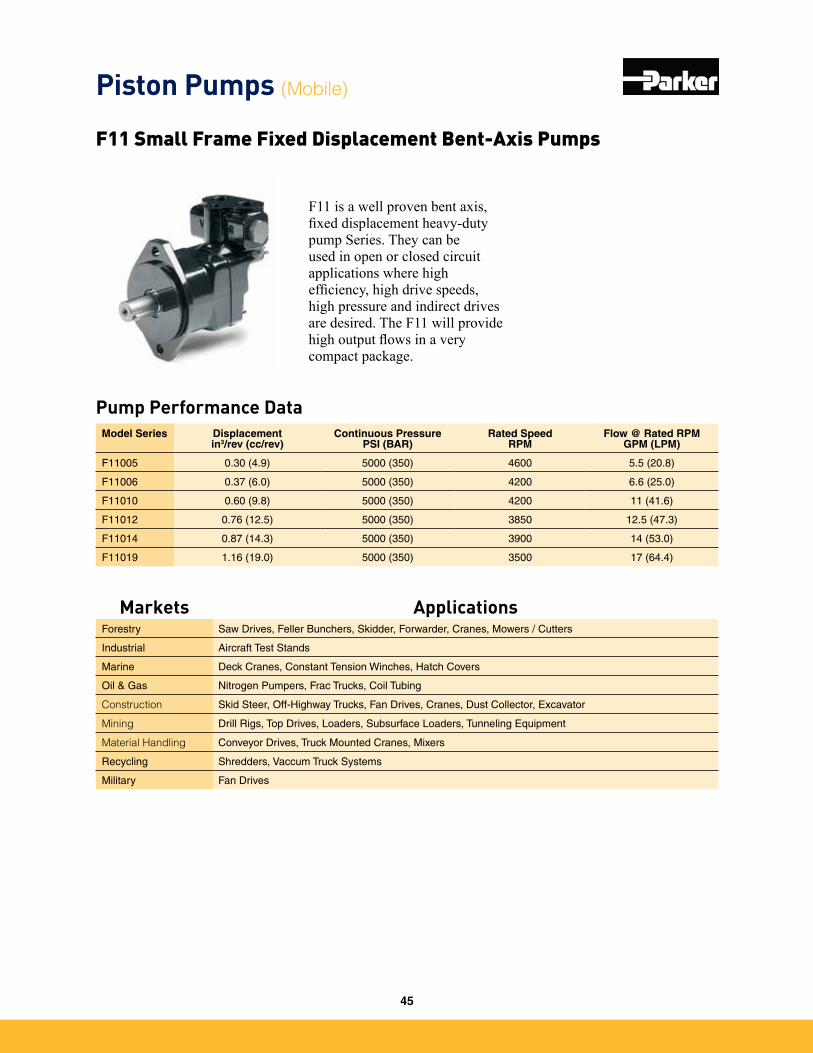
F11 is a well proven bent axis, fixed displacement heavy-duty pump Series. They can be used in open or closed circuit applications where high efficiency, high drive speeds, high pressure and indirect drives are desired. The F11 will provide high output flows in a very compact package.
Pump Performance Data
F11 Small Frame Fixed Displacement Bent-Axis Pumps
Model Series Displacementin3/rev (cc/rev)
Continuous PressurePSI (BAR)
Rated SpeedRPM
Flow @ Rated RPMGPM (LPM)
F11005 0�30 (4�9) 5000 (350) 4600 5�5 (20�8)
F11006 0�37 (6�0) 5000 (350) 4200 6�6 (25�0)
F11010 0�60 (9�8) 5000 (350) 4200 11 (41�6)
F11012 0�76 (12�5) 5000 (350) 3850 12�5 (47�3)
F11014 0�87 (14�3) 5000 (350) 3900 14 (53�0)
F11019 1�16 (19�0) 5000 (350) 3500 17 (64�4)
Piston Pumps (Mobile)
Markets ApplicationsForestry Saw Drives, Feller Bunchers, Skidder, Forwarder, Cranes, Mowers / Cutters
Industrial Aircraft Test Stands
Marine Deck Cranes, Constant Tension Winches, Hatch Covers
Oil & Gas Nitrogen Pumpers, Frac Trucks, Coil Tubing
Construction Skid Steer, Off-Highway Trucks, Fan Drives, Cranes, Dust Collector, Excavator
Mining Drill Rigs, Top Drives, Loaders, Subsurface Loaders, Tunneling Equipment
Material Handling Conveyor Drives, Truck Mounted Cranes, Mixers
Recycling Shredders, Vaccum Truck Systems
Military Fan Drives
45
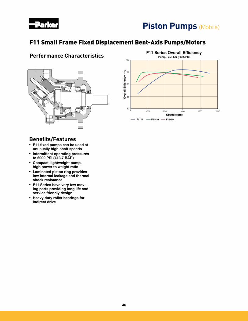
Performance Characteristics
Benefits/Features• F11 fixed pumps can be used at
unusually high shaft speeds• Intermittent operating pressures
to 6000 PSI (413.7 BAR)• Compact, lightweight pump,
high power to weight ratio• Laminated piston ring provides
low internal leakage and thermal shock resistance
• F11 Series have very few mov-ing parts providing long life and service friendly design
• Heavy duty roller bearings for indirect drive
Pump - 250 bar (3625 PSI)
Ove
rall
Eff
icie
ncy
- %
F11-5 F11-10 F11-19
100
95
90
80
85
0 20001000 40003000 5000
Speed (rpm)
F11 Series Overall Efficiency
F11 Small Frame Fixed Displacement Bent-Axis Pumps/Motors
Piston Pumps (Mobile)
46
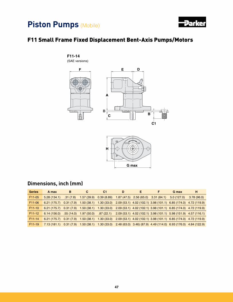
Dimensions, inch (mm)
F11-150(SAE version)
H max
F11-14(SAE versions)
BB
A
CCW CW
A
C
F
B
C1
E D
G max
H
A
G
B
C1
B
C
DEF max
Series A max B C C1 D E F G max H
F11-05 5�28 (134�1) �31 (7�8) 1�57 (39�9) 0�39 (8�89) 1�87 (47�5) 2�56 (65�0) 3�31 (84�1) 5�0 (127�0) 3�78 (96�0)
F11-06 6�21 (175�7) 0�31 (7�9) 1�50 (38�1) 1�30 (33�0) 2�09 (53�1) 4�02 (102�1) 3�98 (101�1) 6�85 (174�0) 4�72 (119�9)
F11-10 6�21 (175�7) 0�31 (7�9) 1�50 (38�1) 1�30 (33�0) 2�09 (53�1) 4�02 (102�1) 3�98 (101�1) 6�85 (174�0) 4�72 (119�9)
F11-12 6�14 (156�0) �55 (14�0) 1�97 (50�0) �87 (22�1) 2�09 (53�1) 4�02 (102�1) 3�98 (101�1) 5�98 (151�9) 4�57 (116�1)
F11-14 6�21 (175�7) 0�31 (7�9) 1�50 (38�1) 1�30 (33�0) 2�09 (53�1) 4�02 (102�1) 3�98 (101�1) 6�85 (174�0) 4�72 (119�9)
F11-19 7�13 (181�1) 0�31 (7�9) 1�50 (38�1) 1�30 (33�0) 2�48 (63�0) 3�46) (87�9) 4�49 (114�0) 6�93 (176�0) 4�84 (122�9)
Piston Pumps (Mobile)
F11 Small Frame Fixed Displacement Bent-Axis Pumps/Motors
47
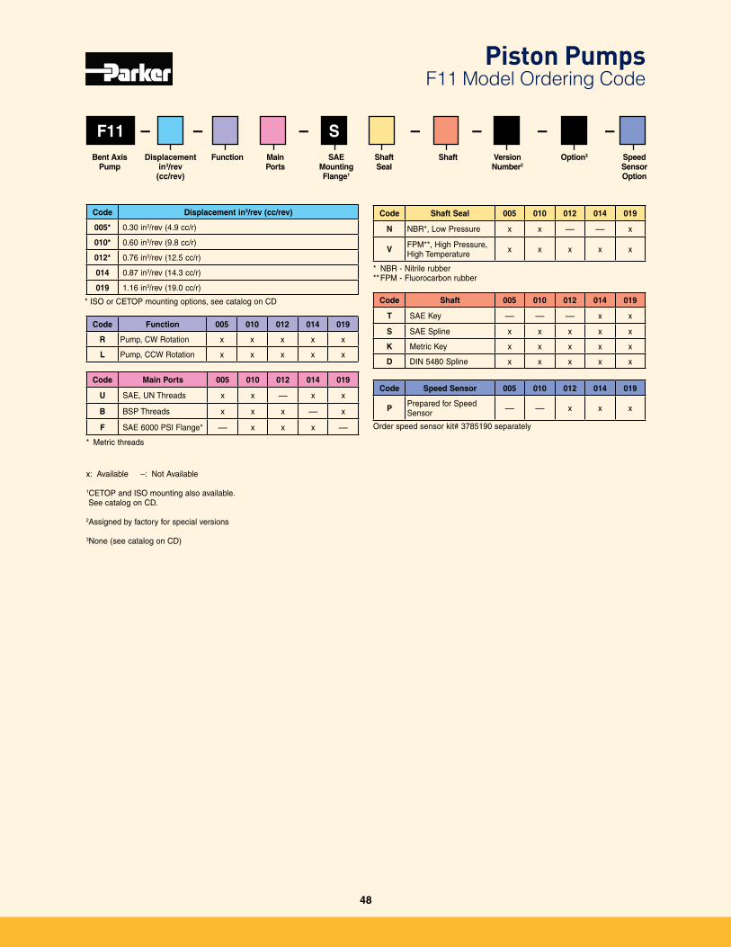
F11
Code Displacement in3/rev (cc/rev)
005* 0�30 in3/rev (4�9 cc/r)
010* 0�60 in3/rev (9�8 cc/r)
012* 0�76 in3/rev (12�5 cc/r)
014 0�87 in3/rev (14�3 cc/r)
019 1�16 in3/rev (19�0 cc/r)
– – –– S – – –
Code Function 005 010 012 014 019
R Pump, CW Rotation x x x x x
L Pump, CCW Rotation x x x x x
Code Main Ports 005 010 012 014 019
U SAE, UN Threads x x — x x
B BSP Threads x x x — x
F SAE 6000 PSI Flange* — x x x —
* Metric threads
Code Shaft Seal 005 010 012 014 019
N NBR*, Low Pressure x x — — x
V FPM**, High Pressure, High Temperature x x x x x
* NBR - Nitrile rubber** FPM - Fluorocarbon rubber
Code Shaft 005 010 012 014 019
T SAE Key — — — x x
S SAE Spline x x x x x
K Metric Key x x x x x
D DIN 5480 Spline x x x x x
Code Speed Sensor 005 010 012 014 019
P Prepared for Speed Sensor — — x x x
x: Available –: Not Available
1CETOP and ISO mounting also available� See catalog on CD�
2Assigned by factory for special versions
3None (see catalog on CD)
Displacementin3/rev
(cc/rev)
Bent Axis Pump
Option3SAEMounting Flange1
Shaft Seal
Shaft Version Number2
Main Ports
Speed Sensor Option
Function
* ISO or CETOP mounting options, see catalog on CD
Order speed sensor kit# 3785190 separately
Piston Pumps F11 Model Ordering Code
48
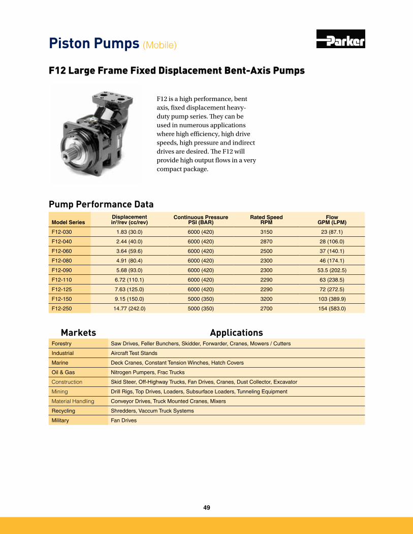
F12 is a high performance, bent axis, fixed displacement heavy-duty pump series. They can be used in numerous applications where high efficiency, high drive speeds, high pressure and indirect drives are desired. The F12 will provide high output flows in a very compact package.
Pump Performance Data
Model SeriesDisplacementin3/rev (cc/rev)
Continuous PressurePSI (BAR)
Rated SpeedRPM
FlowGPM (LPM)
F12-030 1�83 (30�0) 6000 (420) 3150 23 (87�1)
F12-040 2�44 (40�0) 6000 (420) 2870 28 (106�0)
F12-060 3�64 (59�6) 6000 (420) 2500 37 (140�1)
F12-080 4�91 (80�4) 6000 (420) 2300 46 (174�1)
F12-090 5�68 (93�0) 6000 (420) 2300 53�5 (202�5)
F12-110 6�72 (110�1) 6000 (420) 2290 63 (238�5)
F12-125 7�63 (125�0) 6000 (420) 2290 72 (272�5)
F12-150 9�15 (150�0) 5000 (350) 3200 103 (389�9)
F12-250 14�77 (242�0) 5000 (350) 2700 154 (583�0)
F12 Large Frame Fixed Displacement Bent-Axis Pumps
Piston Pumps (Mobile)
Markets ApplicationsForestry Saw Drives, Feller Bunchers, Skidder, Forwarder, Cranes, Mowers / Cutters
Industrial Aircraft Test Stands
Marine Deck Cranes, Constant Tension Winches, Hatch Covers
Oil & Gas Nitrogen Pumpers, Frac Trucks
Construction Skid Steer, Off-Highway Trucks, Fan Drives, Cranes, Dust Collector, Excavator
Mining Drill Rigs, Top Drives, Loaders, Subsurface Loaders, Tunneling Equipment
Material Handling Conveyor Drives, Truck Mounted Cranes, Mixers
Recycling Shredders, Vaccum Truck Systems
Military Fan Drives
49
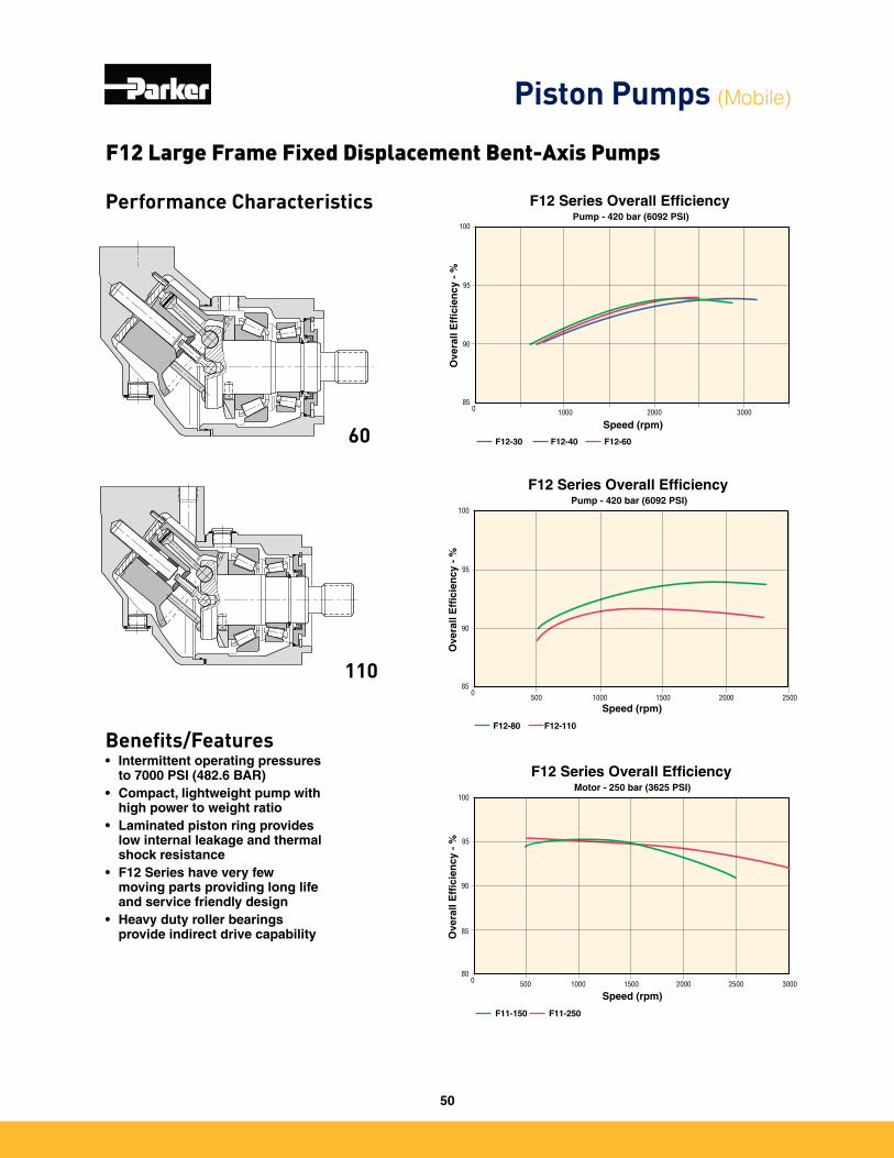
Performance Characteristics
Benefits/Features• Intermittent operating pressures
to 7000 PSI (482.6 BAR)• Compact, lightweight pump with
high power to weight ratio• Laminated piston ring provides
low internal leakage and thermal shock resistance
• F12 Series have very few moving parts providing long life and service friendly design
• Heavy duty roller bearings provide indirect drive capability
60
110
Ove
rall
Eff
icie
ncy
- %
F12-30 F12-40 F12-60
100
95
90
850 2000 30001000
Speed (rpm)
Pump - 420 bar (6092 PSI)
F12 Series Overall Efficiency
Pump - 420 bar (6092 PSI)
Ove
rall
Eff
icie
ncy
- %
F12-80 F12-110
100
95
90
850
2000 25001000 1500500
Speed (rpm)
F12 Series Overall Efficiency
F12 Large Frame Fixed Displacement Bent-Axis Pumps
Piston Pumps (Mobile)
Motor - 250 bar (3625 PSI)
Ove
rall
Eff
icie
ncy
- %
F11-150 F11-250
100
95
90
80
85
0 1500500 1000 25002000 3000
Speed (rpm)
F12 Series Overall Efficiency
50
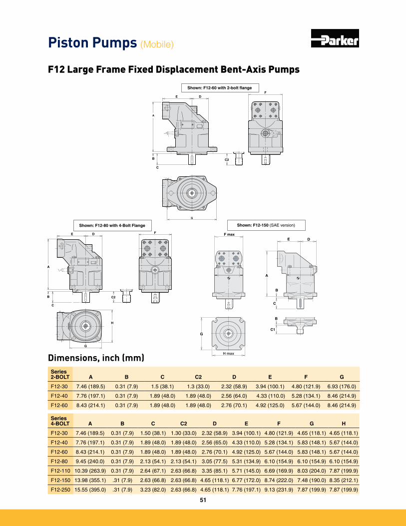
Dimensions, inch (mm)Series 2-BOLT A B C C2 D E F G
F12-30 7�46 (189�5) 0�31 (7�9) 1�5 (38�1) 1�3 (33�0) 2�32 (58�9) 3�94 (100�1) 4�80 (121�9) 6�93 (176�0)
F12-40 7�76 (197�1) 0�31 (7�9) 1�89 (48�0) 1�89 (48�0) 2�56 (64�0) 4�33 (110�0) 5�28 (134�1) 8�46 (214�9)
F12-60 8�43 (214�1) 0�31 (7�9) 1�89 (48�0) 1�89 (48�0) 2�76 (70�1) 4�92 (125�0) 5�67 (144�0) 8�46 (214�9)
Series 4-BOLT A B C C2 D E F G H
F12-30 7�46 (189�5) 0�31 (7�9) 1�50 (38�1) 1�30 (33�0) 2�32 (58�9) 3�94 (100�1) 4�80 (121�9) 4�65 (118�1) 4�65 (118�1)
F12-40 7�76 (197�1) 0�31 (7�9) 1�89 (48�0) 1�89 (48�0) 2�56 (65�0) 4�33 (110�0) 5�28 (134�1) 5�83 (148�1) 5�67 (144�0)
F12-60 8�43 (214�1) 0�31 (7�9) 1�89 (48�0) 1�89 (48�0) 2�76 (70�1) 4�92 (125�0) 5�67 (144�0) 5�83 (148�1) 5�67 (144�0)
F12-80 9�45 (240�0) 0�31 (7�9) 2�13 (54�1) 2�13 (54�1) 3�05 (77�5) 5�31 (134�9) 6�10 (154�9) 6�10 (154�9) 6�10 (154�9)
F12-110 10�39 (263�9) 0�31 (7�9) 2�64 (67�1) 2�63 (66�8) 3�35 (85�1) 5�71 (145�0) 6�69 (169�9) 8�03 (204�0) 7�87 (199�9)
F12-150 13�98 (355�1) �31 (7�9) 2�63 (66�8) 2�63 (66�8) 4�65 (118�1) 6�77 (172�0) 8�74 (222�0) 7�48 (190�0) 8�35 (212�1)
F12-250 15�55 (395�0) �31 (7�9) 3�23 (82�0) 2�63 (66�8) 4�65 (118�1) 7�76 (197�1) 9�13 (231�9) 7�87 (199�9) 7�87 (199�9)
Piston Pumps (Mobile)
F12 Large Frame Fixed Displacement Bent-Axis Pumps
A
C
E DF
B C2
G
Shown: F12-60 with 2-bolt flange
E
A
C
B
D F
C2
G
H
Shown: F12-80 with 4-Bolt Flange
A
C
E DF
B C2
G
Shown: F12-60 with 2-bolt flange
E
A
C
B
D F
C2
G
H
Shown: F12-80 with 4-Bolt Flange
H max
A
G
B
C1
B
C
DEF max
Shown: F12-150 (SAE version)
51
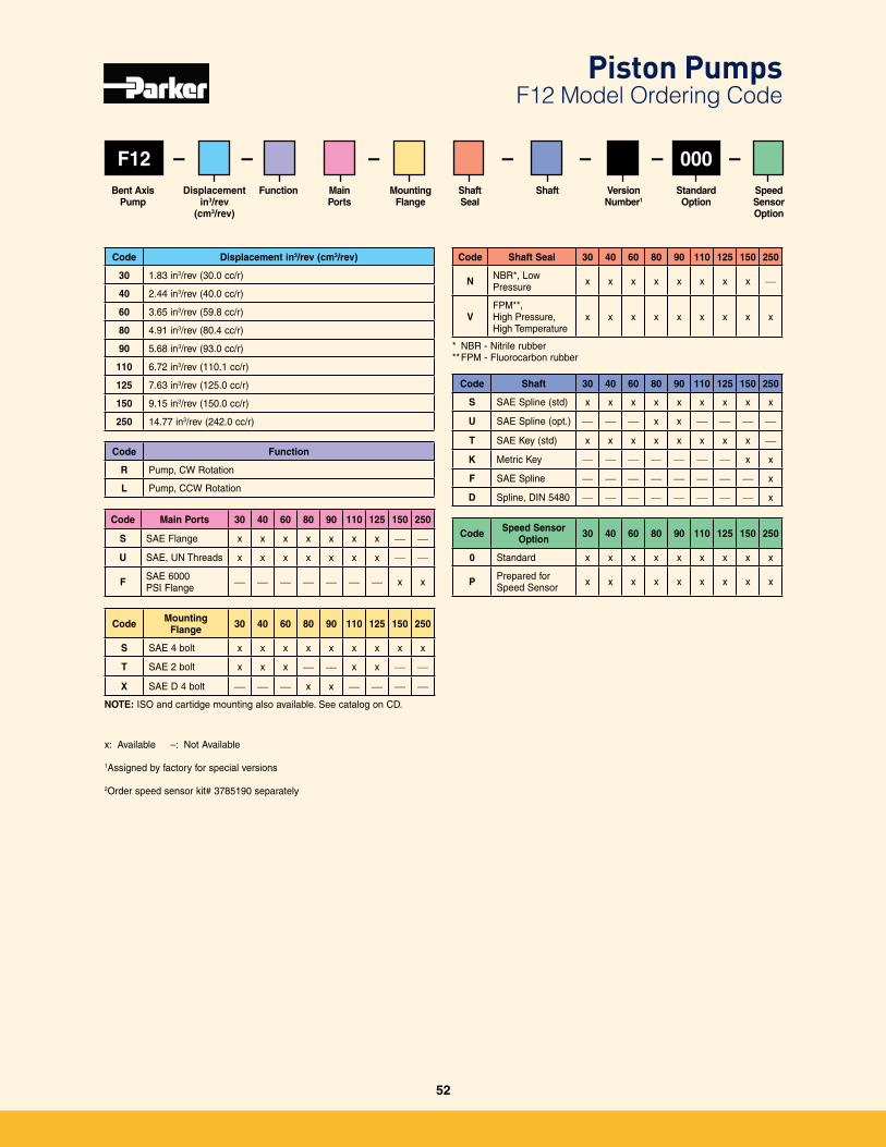
F12
Code Displacement in3/rev (cm3/rev)
30 1�83 in3/rev (30�0 cc/r)
40 2�44 in3/rev (40�0 cc/r)
60 3�65 in3/rev (59�8 cc/r)
80 4�91 in3/rev (80�4 cc/r)
90 5�68 in3/rev (93�0 cc/r)
110 6�72 in3/rev (110�1 cc/r)
125 7�63 in3/rev (125�0 cc/r)
150 9�15 in3/rev (150�0 cc/r)
250 14�77 in3/rev (242�0 cc/r)
Displacementin3/rev
(cm3/rev)
StandardOption
Mounting Flange
Shaft Seal
Shaft Version Number1
Main Ports
– – –Speed Sensor Option
– – – –000Function
Code Main Ports 30 40 60 80 90 110 125 150 250
S SAE Flange x x x x x x x — —
U SAE, UN Threads x x x x x x x — —
F SAE 6000 PSI Flange — — — — — — — x x
Code Shaft Seal 30 40 60 80 90 110 125 150 250
N NBR*, Low Pressure x x x x x x x x —
VFPM**, High Pressure, High Temperature
x x x x x x x x x
* NBR - Nitrile rubber** FPM - Fluorocarbon rubber
Code Function
R Pump, CW Rotation
L Pump, CCW Rotation
Code Mounting Flange 30 40 60 80 90 110 125 150 250
S SAE 4 bolt x x x x x x x x x
T SAE 2 bolt x x x — — x x — —
X SAE D 4 bolt — — — x x — — — —
NOTE: ISO and cartidge mounting also available� See catalog on CD�
Code Shaft 30 40 60 80 90 110 125 150 250
S SAE Spline (std) x x x x x x x x x
U SAE Spline (opt�) — — — x x — — — —
T SAE Key (std) x x x x x x x x —
K Metric Key — — — — — — — x x
F SAE Spline — — — — — — — — x
D Spline, DIN 5480 — — — — — — — — x
Code Speed Sensor Option 30 40 60 80 90 110 125 150 250
0 Standard x x x x x x x x x
P Prepared for Speed Sensor x x x x x x x x x
x: Available –: Not Available
1Assigned by factory for special versions
2Order speed sensor kit# 3785190 separately
Bent Axis Pump
Piston Pumps F12 Model Ordering Code
52
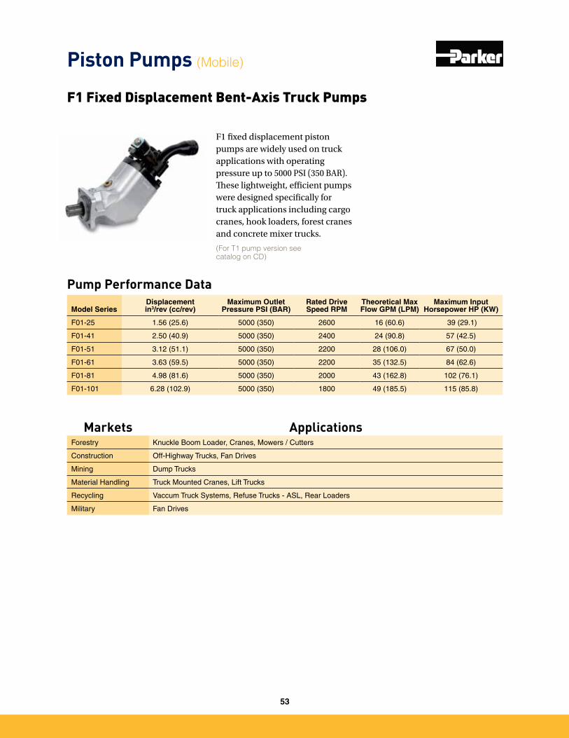
F1 fixed displacement piston pumps are widely used on truck applications with operating pressure up to 5000 PSI (350 BAR). These lightweight, efficient pumps were designed specifically for truck applications including cargo cranes, hook loaders, forest cranes and concrete mixer trucks.
Pump Performance Data
F1 Fixed Displacement Bent-Axis Truck Pumps
Model Series Displacementin3/rev (cc/rev)
Maximum Outlet Pressure PSI (BAR)
Rated Drive Speed RPM
Theoretical Max Flow GPM (LPM)
Maximum Input Horsepower HP (KW)
F01-25 1�56 (25�6) 5000 (350) 2600 16 (60�6) 39 (29�1)
F01-41 2�50 (40�9) 5000 (350) 2400 24 (90�8) 57 (42�5)
F01-51 3�12 (51�1) 5000 (350) 2200 28 (106�0) 67 (50�0)
F01-61 3�63 (59�5) 5000 (350) 2200 35 (132�5) 84 (62�6)
F01-81 4�98 (81�6) 5000 (350) 2000 43 (162�8) 102 (76�1)
F01-101 6�28 (102�9) 5000 (350) 1800 49 (185�5) 115 (85�8)
(For T1 pump version see catalog on CD)
Piston Pumps (Mobile)
Markets ApplicationsForestry Knuckle Boom Loader, Cranes, Mowers / Cutters
Construction Off-Highway Trucks, Fan Drives
Mining Dump Trucks
Material Handling Truck Mounted Cranes, Lift Trucks
Recycling Vaccum Truck Systems, Refuse Trucks - ASL, Rear Loaders
Military Fan Drives
53
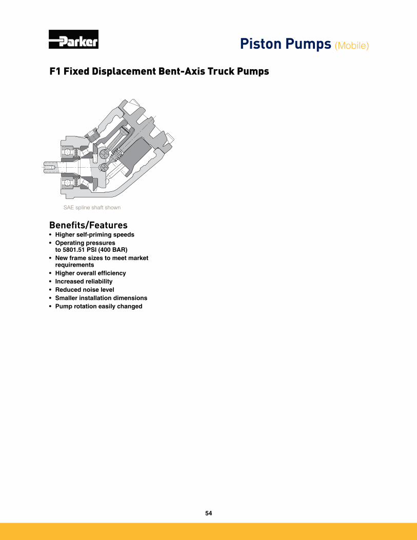
Benefits/Features• Higher self-priming speeds• Operating pressures
to 5801.51 PSI (400 BAR)• New frame sizes to meet market
requirements• Higher overall efficiency• Increased reliability• Reduced noise level• Smaller installation dimensions• Pump rotation easily changed
SAE spline shaft shown
F1 Fixed Displacement Bent-Axis Truck Pumps
Piston Pumps (Mobile)
54
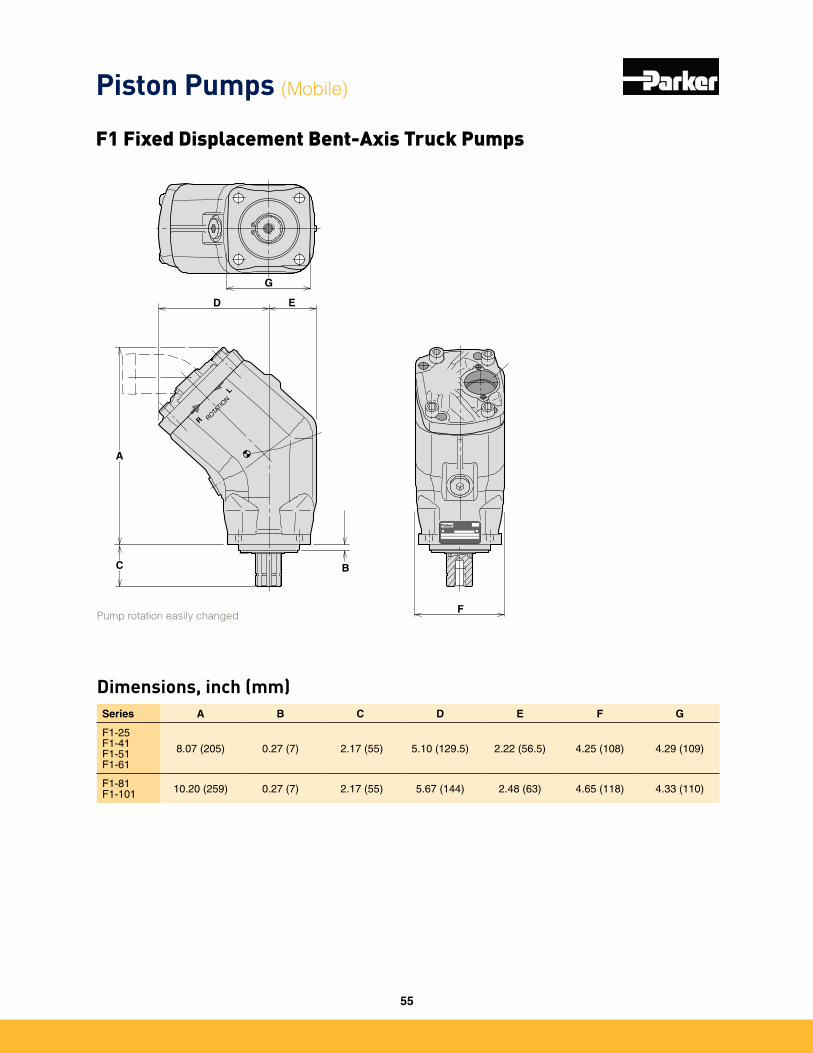
Dimensions, inch (mm)
Parker
C
A
B
F
G
D E
R ROTA
TION L
Series A B C D E F G
F1-25 F1-41 F1-51 F1-61
8�07 (205) 0�27 (7) 2�17 (55) 5�10 (129�5) 2�22 (56�5) 4�25 (108) 4�29 (109)
F1-81 F1-101 10�20 (259) 0�27 (7) 2�17 (55) 5�67 (144) 2�48 (63) 4�65 (118) 4�33 (110)
Pump rotation easily changed
Piston Pumps (Mobile)
F1 Fixed Displacement Bent-Axis Truck Pumps
55
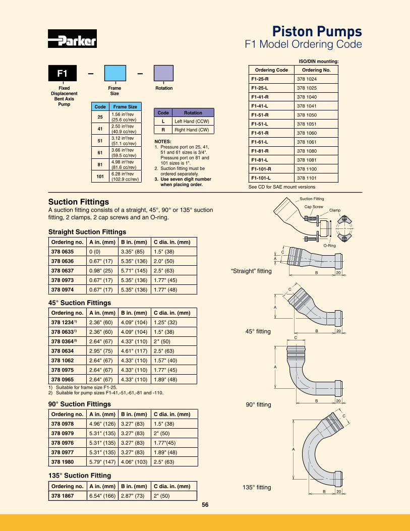
“Straight” fitting
45° fitting
90° fitting
135° fitting
Ordering no. A in. (mm) B in. (mm) C dia. in. (mm)
378 0635 0 (0) 3�35" (85) 1�5" (38)
378 0636 0�67" (17) 5�35" (136) 2�0" (50)
378 0637 0�98" (25) 5�71" (145) 2�5" (63)
378 0973 0�67" (17) 5�35" (136) 1�77" (45)
378 0974 0�67" (17) 5�35" (136) 1�77" (48)
Suction FittingsA suction fitting consists of a straight, 45°, 90° or 135° suction fitting, 2 clamps, 2 cap screws and an O-ring�
Straight Suction Fittings
Ordering no. A in. (mm) B in. (mm) C dia. in. (mm)
378 12341) 2�36" (60) 4�09" (104) 1�25" (32)
378 06331) 2�36" (60) 4�09" (104) 1�5" (38)
378 03642) 2�64" (67) 4�33" (110) 2" (50)
378 0634 2�95" (75) 4�61" (117) 2�5" (63)
378 1062 2�64" (67) 4�33" (110) 1�57" (40)
378 0975 2�64" (67) 4�33" (110) 1�77" (45)
378 0965 2�64" (67) 4�33" (110) 1�89" (48)1) Suitable for frame size F1-25�2) Suitable for pump sizes F1-41,-51,-61,-81 and -110�
Ordering no. A in. (mm) B in. (mm) C dia. in. (mm)
378 0978 4�96" (126) 3�27" (83) 1�5" (38)
378 0979 5�31" (135) 3�27" (83) 2" (50)
378 0976 5�31" (135) 3�27" (83) 1�77"(45)
378 0977 5�31" (135) 3�27" (83) 1�89" (48)
378 1980 5�79" (147) 4�06" (103) 2�5" (63)
45° Suction Fittings
90° Suction Fittings
Ordering no. A in. (mm) B in. (mm) C dia. in. (mm)
378 1867 6�54" (166) 2�87" (73) 2" (50)
135° Suction Fitting
C
C
C
C
A
A
A
B 20
B 20
B 20
A
B 20
O-Ring
Suction Fitting
Cap ScrewClamp
F1
Code Frame Size
25 1�56 in3/rev(25�6 cc/rev)
41 2�50 in3/rev(40�9 cc/rev)
51 3�12 in3/rev(51�1 cc/rev)
61 3�66 in3/rev(59�5 cc/rev)
81 4�98 in3/rev(81�6 cc/rev)
101 6�28 in3/rev(102�9 cc/rev)
Code Rotation
L Left Hand (CCW)
R Right Hand (CW)
Frame Size
Fixed Displacenent
Bent Axis Pump
Rotation
– – Ordering Code Ordering No.
F1-25-R 378 1024
F1-25-L 378 1025
F1-41-R 378 1040
F1-41-L 378 1041
F1-51-R 378 1050
F1-51-L 378 1051
F1-61-R 378 1060
F1-61-L 378 1061
F1-81-R 378 1080
F1-81-L 378 1081
F1-101-R 378 1100
F1-101-L 378 1101
NOTES: 1� Pressure port on 25, 41,
51 and 61 sizes is 3/4"� Pressure port on 81 and 101 sizes is 1"�
2� Suction fitting must be ordered separately�
3. Use seven digit number when placing order.
ISO/DIN mounting:
See CD for SAE mount versions
Piston Pumps F1 Model Ordering Code
56
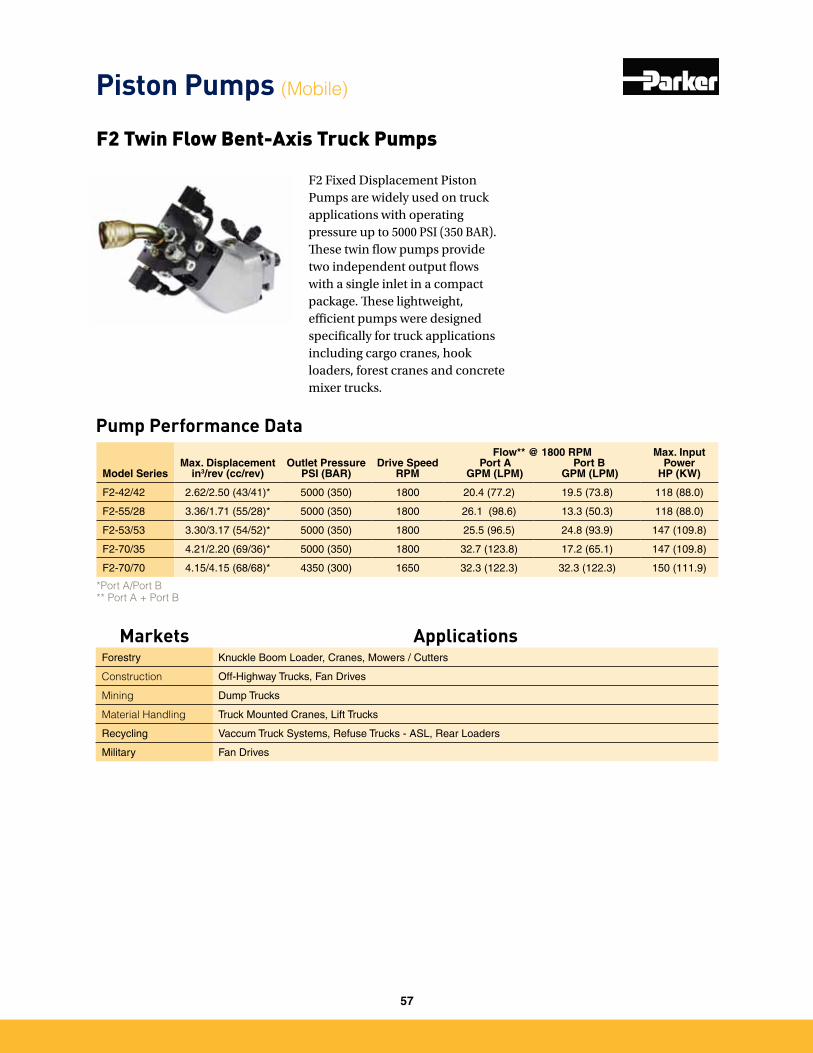
F2 Fixed Displacement Piston Pumps are widely used on truck applications with operating pressure up to 5000 PSI (350 BAR). These twin flow pumps provide two independent output flows with a single inlet in a compact package. These lightweight, efficient pumps were designed specifically for truck applications including cargo cranes, hook loaders, forest cranes and concrete mixer trucks.
Pump Performance Data
F2 Twin Flow Bent-Axis Truck Pumps
Model SeriesMax. Displacement
in3/rev (cc/rev)Outlet Pressure
PSI (BAR)Drive Speed
RPM
Flow** @ 1800 RPM Port A Port B
GPM (LPM) GPM (LPM)
Max. Input Power
HP (KW)
F2-42/42 2�62/2�50 (43/41)* 5000 (350) 1800 20�4 (77�2) 19�5 (73�8) 118 (88�0)
F2-55/28 3�36/1�71 (55/28)* 5000 (350) 1800 26�1 (98�6) 13�3 (50�3) 118 (88�0)
F2-53/53 3�30/3�17 (54/52)* 5000 (350) 1800 25�5 (96�5) 24�8 (93�9) 147 (109�8)
F2-70/35 4�21/2�20 (69/36)* 5000 (350) 1800 32�7 (123�8) 17�2 (65�1) 147 (109�8)
F2-70/70 4�15/4�15 (68/68)* 4350 (300) 1650 32�3 (122�3) 32�3 (122�3) 150 (111�9)
*Port A/Port B ** Port A + Port B
Piston Pumps (Mobile)
Markets ApplicationsForestry Knuckle Boom Loader, Cranes, Mowers / Cutters
Construction Off-Highway Trucks, Fan Drives
Mining Dump Trucks
Material Handling Truck Mounted Cranes, Lift Trucks
Recycling Vaccum Truck Systems, Refuse Trucks - ASL, Rear Loaders
Military Fan Drives
57
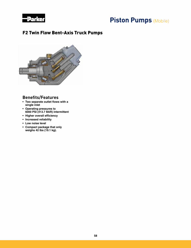
Benefits/Features• Two separate outlet flows with a
single inlet • Operating pressures to
6000 PSI (413.7 BAR) intermittent• Higher overall efficiency• Increased reliability• Low noise level• Compact package that only
weighs 42 lbs (19.1 kg).
F2 Twin Flow Bent-Axis Truck Pumps
Piston Pumps (Mobile)
58
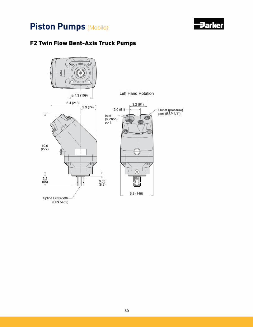
10.9(277)
2.2(55) 0.33
(8.5)
8.4 (213)
4.3 (109)
2.9 (74)
5.8 (148)
B
Left Hand Rotation
Spline B8x32x36 (DIN 5462)
Inlet (suction) port
Outlet (pressure)port (BSP 3/4")
3.2 (81)
2.0 (51)
Piston Pumps (Mobile)
F2 Twin Flow Bent-Axis Truck Pumps
59
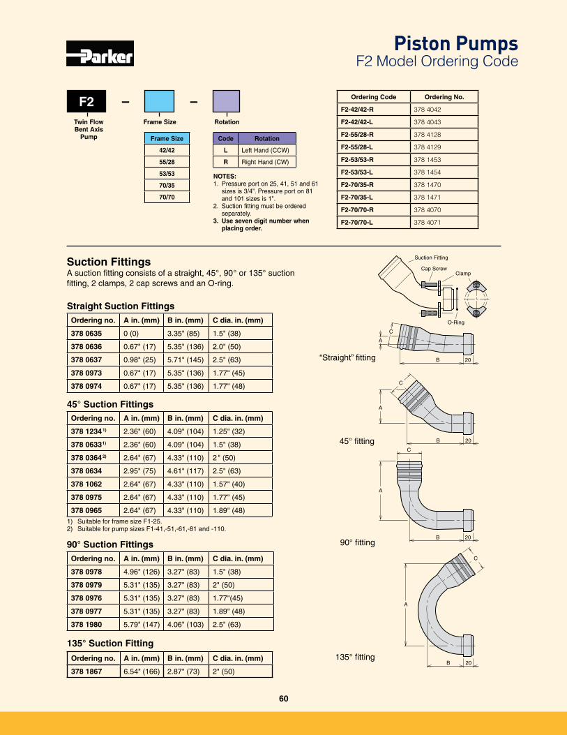
F2
Frame Size
42/42
55/28
53/53
70/35
70/70
Code Rotation
L Left Hand (CCW)
R Right Hand (CW)
Frame SizeTwin Flow Bent Axis
Pump
Rotation
– – Ordering Code Ordering No.
F2-42/42-R 378 4042
F2-42/42-L 378 4043
F2-55/28-R 378 4128
F2-55/28-L 378 4129
F2-53/53-R 378 1453
F2-53/53-L 378 1454
F2-70/35-R 378 1470
F2-70/35-L 378 1471
F2-70/70-R 378 4070
F2-70/70-L 378 4071
“Straight” fitting
45° fitting
90° fitting
135° fitting
Suction FittingsA suction fitting consists of a straight, 45°, 90° or 135° suction fitting, 2 clamps, 2 cap screws and an O-ring�
C
C
C
C
A
A
A
B 20
B 20
B 20
A
B 20
O-Ring
Suction Fitting
Cap ScrewClamp
NOTES: 1� Pressure port on 25, 41, 51 and 61
sizes is 3/4"� Pressure port on 81 and 101 sizes is 1"�
2� Suction fitting must be ordered separately�
3. Use seven digit number when placing order.
Piston Pumps F2 Model Ordering Code
Ordering no. A in. (mm) B in. (mm) C dia. in. (mm)
378 0635 0 (0) 3�35" (85) 1�5" (38)
378 0636 0�67" (17) 5�35" (136) 2�0" (50)
378 0637 0�98" (25) 5�71" (145) 2�5" (63)
378 0973 0�67" (17) 5�35" (136) 1�77" (45)
378 0974 0�67" (17) 5�35" (136) 1�77" (48)
Straight Suction Fittings
Ordering no. A in. (mm) B in. (mm) C dia. in. (mm)
378 12341) 2�36" (60) 4�09" (104) 1�25" (32)
378 06331) 2�36" (60) 4�09" (104) 1�5" (38)
378 03642) 2�64" (67) 4�33" (110) 2" (50)
378 0634 2�95" (75) 4�61" (117) 2�5" (63)
378 1062 2�64" (67) 4�33" (110) 1�57" (40)
378 0975 2�64" (67) 4�33" (110) 1�77" (45)
378 0965 2�64" (67) 4�33" (110) 1�89" (48)1) Suitable for frame size F1-25�2) Suitable for pump sizes F1-41,-51,-61,-81 and -110�
Ordering no. A in. (mm) B in. (mm) C dia. in. (mm)
378 0978 4�96" (126) 3�27" (83) 1�5" (38)
378 0979 5�31" (135) 3�27" (83) 2" (50)
378 0976 5�31" (135) 3�27" (83) 1�77"(45)
378 0977 5�31" (135) 3�27" (83) 1�89" (48)
378 1980 5�79" (147) 4�06" (103) 2�5" (63)
45° Suction Fittings
90° Suction Fittings
Ordering no. A in. (mm) B in. (mm) C dia. in. (mm)
378 1867 6�54" (166) 2�87" (73) 2" (50)
135° Suction Fitting
60

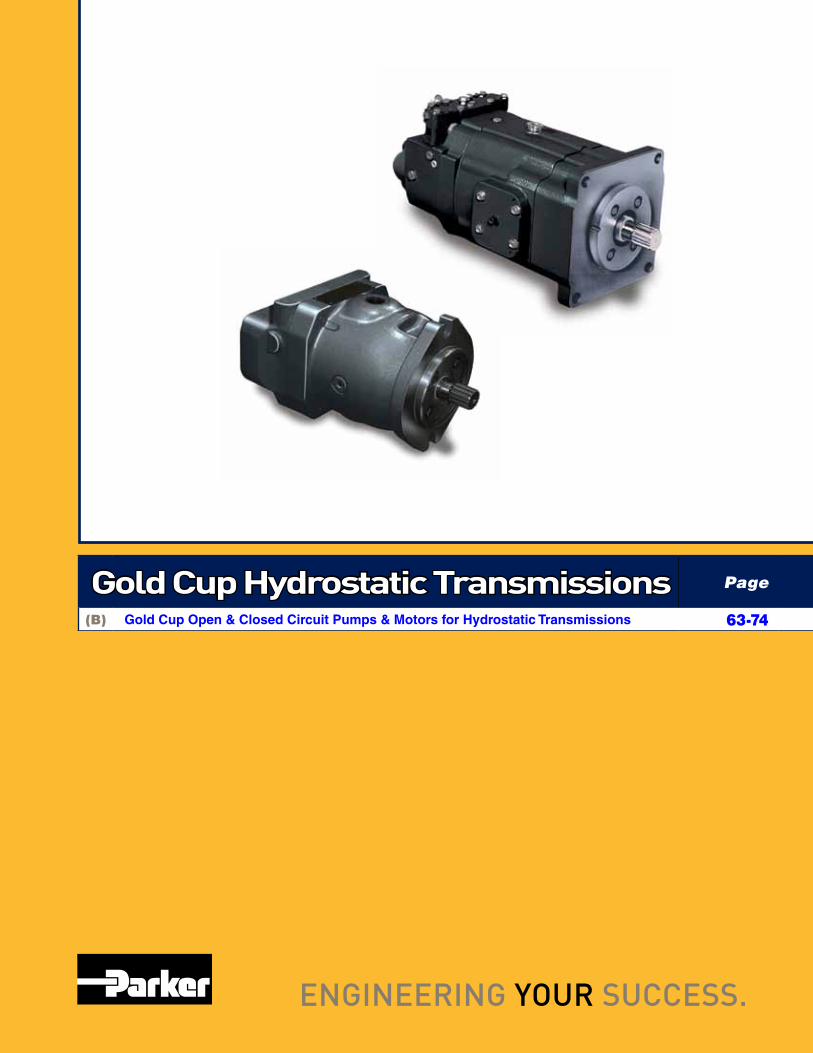
Gold Cup Hydrostatic Transmissions Page
(B) Gold Cup Open & Closed Circuit Pumps & Motors for Hydrostatic Transmissions 63-74
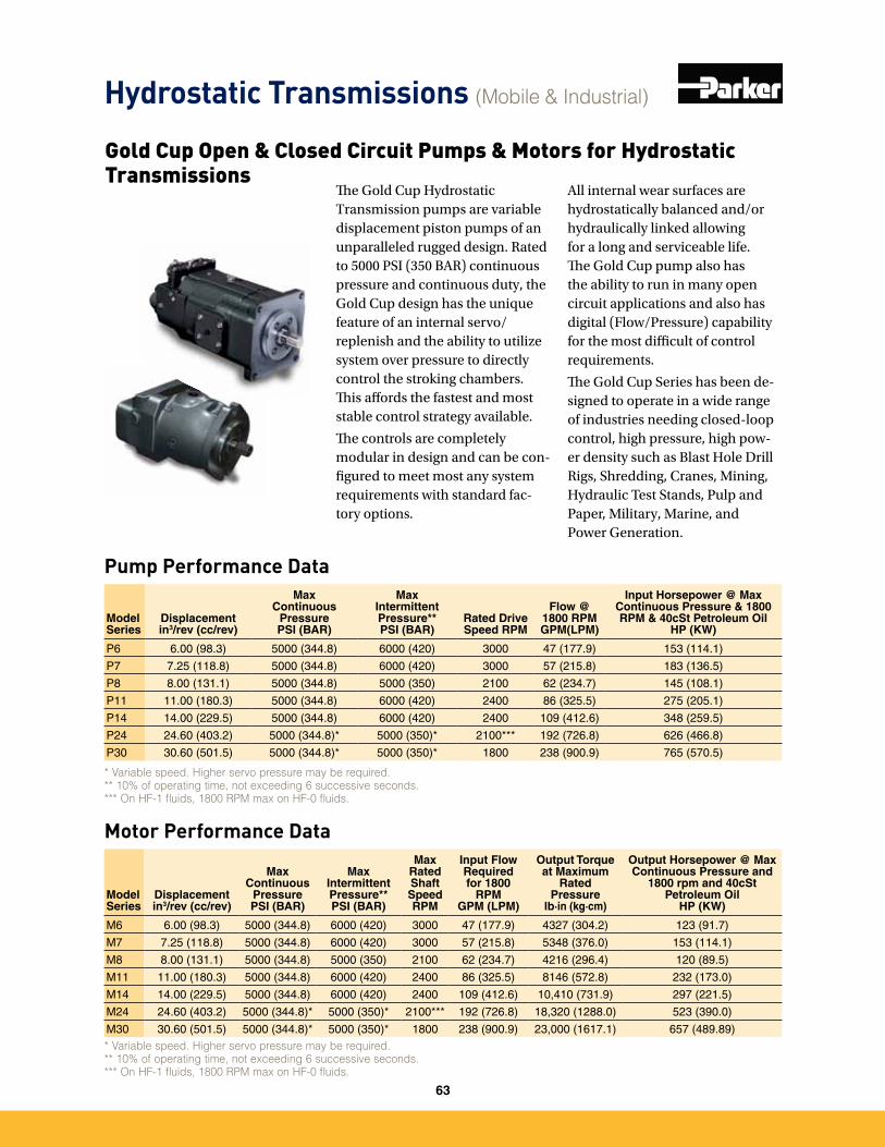
Pump Performance Data
Model Series
Displacementin3/rev (cc/rev)
Max Continuous
Pressure PSI (BAR)
Max Intermittent Pressure** PSI (BAR)
Rated Drive Speed RPM
Flow @ 1800 RPMGPM(LPM)
Input Horsepower @ Max Continuous Pressure & 1800 RPM & 40cSt Petroleum Oil
HP (KW)
P6 6�00 (98�3) 5000 (344�8) 6000 (420) 3000 47 (177�9) 153 (114�1)
P7 7�25 (118�8) 5000 (344�8) 6000 (420) 3000 57 (215�8) 183 (136�5)
P8 8�00 (131�1) 5000 (344�8) 5000 (350) 2100 62 (234�7) 145 (108�1)
P11 11�00 (180�3) 5000 (344�8) 6000 (420) 2400 86 (325�5) 275 (205�1)
P14 14�00 (229�5) 5000 (344�8) 6000 (420) 2400 109 (412�6) 348 (259�5)
P24 24�60 (403�2) 5000 (344�8)* 5000 (350)* 2100*** 192 (726�8) 626 (466�8)
P30 30�60 (501�5) 5000 (344�8)* 5000 (350)* 1800 238 (900�9) 765 (570�5)
* Variable speed. Higher servo pressure may be required. ** 10% of operating time, not exceeding 6 successive seconds.*** On HF-1 fluids, 1800 RPM max on HF-0 fluids.
Motor Performance Data
Model Series
Displacementin3/rev (cc/rev)
Max Continuous
PressurePSI (BAR)
Max Intermittent Pressure**PSI (BAR)
Max Rated Shaft SpeedRPM
Input Flow Required for 1800
RPMGPM (LPM)
Output Torque at Maximum
Rated Pressure
lb·in (kg·cm)
Output Horsepower @ Max Continuous Pressure and
1800 rpm and 40cSt Petroleum Oil
HP (KW)
M6 6�00 (98�3) 5000 (344�8) 6000 (420) 3000 47 (177�9) 4327 (304�2) 123 (91�7)
M7 7�25 (118�8) 5000 (344�8) 6000 (420) 3000 57 (215�8) 5348 (376�0) 153 (114�1)
M8 8�00 (131�1) 5000 (344�8) 5000 (350) 2100 62 (234�7) 4216 (296�4) 120 (89�5)
M11 11�00 (180�3) 5000 (344�8) 6000 (420) 2400 86 (325�5) 8146 (572�8) 232 (173�0)
M14 14�00 (229�5) 5000 (344�8) 6000 (420) 2400 109 (412�6) 10,410 (731�9) 297 (221�5)
M24 24�60 (403�2) 5000 (344�8)* 5000 (350)* 2100*** 192 (726�8) 18,320 (1288�0) 523 (390�0)
M30 30�60 (501�5) 5000 (344�8)* 5000 (350)* 1800 238 (900�9) 23,000 (1617�1) 657 (489�89)* Variable speed. Higher servo pressure may be required. ** 10% of operating time, not exceeding 6 successive seconds.*** On HF-1 fluids, 1800 RPM max on HF-0 fluids.
The Gold Cup Hydrostatic Transmission pumps are variable displacement piston pumps of an unparalleled rugged design. Rated to 5000 PSI (350 BAR) continuous pressure and continuous duty, the Gold Cup design has the unique feature of an internal servo/replenish and the ability to utilize system over pressure to directly control the stroking chambers. This affords the fastest and most stable control strategy available.
The controls are completely modular in design and can be con-figured to meet most any system requirements with standard fac-tory options.
All internal wear surfaces are hydrostatically balanced and/or hydraulically linked allowing for a long and serviceable life. The Gold Cup pump also has the ability to run in many open circuit applications and also has digital (Flow/Pressure) capability for the most difficult of control requirements.
The Gold Cup Series has been de-signed to operate in a wide range of industries needing closed-loop control, high pressure, high pow-er density such as Blast Hole Drill Rigs, Shredding, Cranes, Mining, Hydraulic Test Stands, Pulp and Paper, Military, Marine, and Power Generation.
Hydrostatic Transmissions (Mobile & Industrial)
Gold Cup Open & Closed Circuit Pumps & Motors for Hydrostatic Transmissions
63
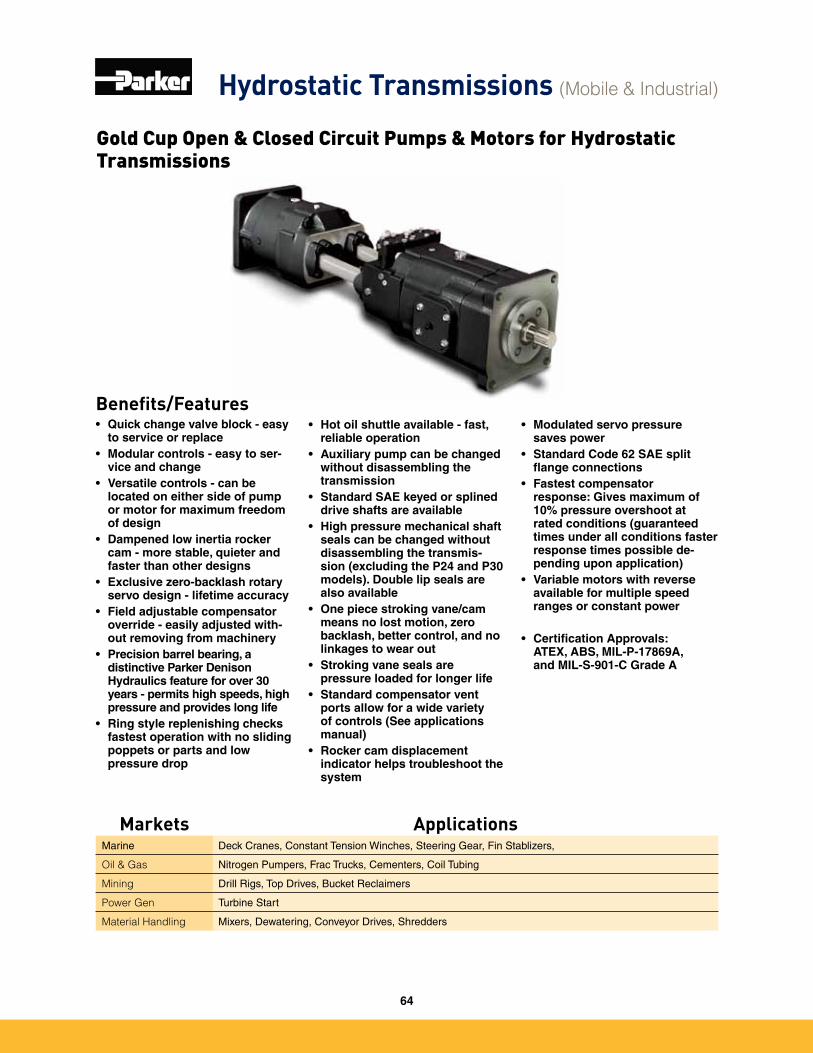
Benefits/Features• Quick change valve block - easy
to service or replace• Modular controls - easy to ser-
vice and change• Versatile controls - can be
located on either side of pump or motor for maximum freedom of design
• Dampened low inertia rocker cam - more stable, quieter and faster than other designs
• Exclusive zero-backlash rotary servo design - lifetime accuracy
• Field adjustable compensator override - easily adjusted with-out removing from machinery
• Precision barrel bearing, a distinctive Parker Denison Hydraulics feature for over 30 years - permits high speeds, high pressure and provides long life
• Ring style replenishing checks fastest operation with no sliding poppets or parts and low pressure drop
• Hot oil shuttle available - fast, reliable operation
• Auxiliary pump can be changed without disassembling the transmission
• Standard SAE keyed or splined drive shafts are available
• High pressure mechanical shaft seals can be changed without disassembling the transmis-sion (excluding the P24 and P30 models). Double lip seals are also available
• One piece stroking vane/cam means no lost motion, zero backlash, better control, and no linkages to wear out
• Stroking vane seals are pressure loaded for longer life
• Standard compensator vent ports allow for a wide variety of controls (See applications manual)
• Rocker cam displacement indicator helps troubleshoot the system
Hydrostatic Transmissions (Mobile & Industrial)
Gold Cup Open & Closed Circuit Pumps & Motors for Hydrostatic Transmissions
• Modulated servo pressure saves power
• Standard Code 62 SAE split flange connections
• Fastest compensator response: Gives maximum of 10% pressure overshoot at rated conditions (guaranteed times under all conditions faster response times possible de-pending upon application)
• Variable motors with reverse available for multiple speed ranges or constant power
• Certification Approvals: ATEX, ABS, MIL-P-17869A, and MIL-S-901-C Grade A
Markets ApplicationsMarine Deck Cranes, Constant Tension Winches, Steering Gear, Fin Stablizers,
Oil & Gas Nitrogen Pumpers, Frac Trucks, Cementers, Coil Tubing
Mining Drill Rigs, Top Drives, Bucket Reclaimers
Power Gen Turbine Start
Material Handling Mixers, Dewatering, Conveyor Drives, Shredders
64
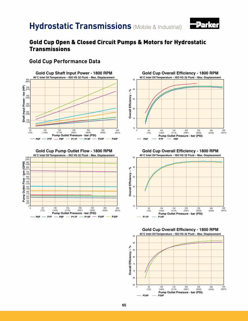
Gold Cup Performance Data
Gold Cup Pump Outlet Flow - 1800 RPM40˚C Inlet Oil Temperature – ISO VG 32 Fluid – Max. Displacement
0
Pump Outlet Pressure - bar (PSI)
Pu
mp
Ou
tlet
Flo
w -
lpm
(G
PM
)
0
400(106)
200(53)
600 (159)
800 (211)
1000(264)
100(1450)
200(2901)
250 (3626)
350(5075)
300 (4350)
P6P P7P P8P P11P P14P
50(725)
150(2176)
P24P P30P
900(238)
700(185)
500(132)
300(79)
100(26)
Gold Cup Overall Efficiency - 1800 RPM
0
Pump Outlet Pressure - bar (PSI)
Ove
rall
Eff
icie
ncy
– %
70
80
75
85
90
95
P6P P7P P8P
40˚C Inlet Oil Temperature – ISO VG 32 Fluid – Max. Displacement
100(1450)
200(2901)
250 (3626)
350(5075)
300 (4350)
50(725)
150(2176)
Gold Cup Overall Efficiency - 1800 RPM
0
Pump Outlet Pressure - bar (PSI)
Ove
rall
Eff
icie
ncy
– %
70
80
75
85
90
95
P11P P14P
40˚C Inlet Oil Temperature – ISO VG 32 Fluid – Max. Displacement
100(1450)
200(2901)
250 (3626)
350(5075)
300 (4350)
50(725)
150(2176)
Gold Cup Overall Efficiency - 1800 RPM
0
Pump Outlet Pressure - bar (PSI)
Ove
rall
Eff
icie
ncy
– %
70
80
75
85
90
95
P24P P30P
40˚C Inlet Oil Temperature – ISO VG 32 Fluid – Max. Displacement
100(1450)
200(2901)
250 (3626)
350(5075)
300 (4350)
50(725)
150(2176)
60
65
Gold Cup Shaft Input Power - 1800 RPM40˚C Inlet Oil Temperature – ISO VG 32 Fluid – Max. Displacement
Pump Outlet Pressure - bar (PSI)
Sh
aft
Inp
ut
Po
wer
- k
w (
HP
)
0
200(268)
100(134)
300 (402)
400 (536)
500(670)
100(1450)
200(2901)
250 (3626)
350(5075)
300 (4350)
P6P P7P P8P P11P P14P
50(725)
150(2176)
P24P P30P
600(804)
Hydrostatic Transmissions (Mobile & Industrial)
Gold Cup Open & Closed Circuit Pumps & Motors for Hydrostatic Transmissions
65
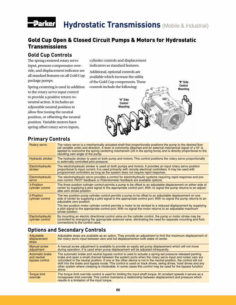
Primary ControlsRotary servo The rotary servo is a mechanically actuated shaft that proportionally positions the pump to the desired flow
(all variable units) and direction� A lever is commonly attached and an external mechanical signal of ±19° is applied to overcome the spring centering mechanism (20 in lbs spring force) and is directly proportional to the resulting cam angle of the pump�
Hydraulic stroker The hydraulic stroker is used on both pump and motors� This control positions the rotary servo proportionally to externally controlled pilot pressure�
Electrohydraulic stroker
The electrohydraulic stroker is used on both pumps and motors� It provides an input rotary servo position proportional to input current� It is used primarily with remote electrical controllers� It may be used with programmed controllers as long as the system does not require rapid response�
Electrohydraulic servo
The electrohydraulic servo provides a control for electrohydraulic systems requiring rapid response and pre-cise control� RVDT feedback or Potentiometer feedback are available options�
3-Position cylinder control
The three position cylinder control permits a pump to be offset to an adjustable displacement on either side of center by supplying a pilot signal to the appropriate control port� With no signal the pump returns to an adjust-able zero stroke position�
2-Position cylinder control
The two position pump cylinder control permits a pump to be offset to an adjustable displacement on one side of center by supplying a pilot signal to the appropriate control port� With no signal the pump returns to an adjustable zero position� The two position motor cylinder control permits a motor to be stroked to a reduced displacement by supplying a pilot signal to the appropriate control port� With no signal the motor returns to an adjustable maximum stroke position�
Electrohydraulic cylinder control
By mounting an electric directional control valve on the cylinder control, the pump or motor stroke may be controlled by energizing the appropriate solenoid valve, eliminating the need for separate mounting and fluid connections to the control valve�
Options and Secondary ControlsAdjustable displacement stops
Adjustable stops are available as an option� They provide an adjustment to limit the maximum displacement of the rotary servo input between zero and full displacementon both sides of center�
Manual screw adjustment
A manual screw adjustment is available to provide an easily set pump displacement which will not move during operation� It is used when pump displacement will be adjusted infrequently�
Automatic brake and neutral bypass control
The automatic brake and neutral bypass control is used to actuate a spring set pressure released parking brake and open a small channel between the system ports when the rotary servo input and rocker cam are coincident in the neutral position� If one or the other device is not in the neutral position, the control will not shift into the brake and bypass mode� This control is used on track drives, swing drives, hoist drives and any other system where creeping is intolerable� In some cases this control may be used for the bypass function alone�
Torque limit override
The torque limit override control is used for limiting the input shaft torque� At constant speeds it serves as a horsepower limit override� This control maintains a relationship between displacement and pressure which results in a limitation of the input torque�
"A" Side Control
Mounting
"B" Side Control
Mounting
Gold Cup ControlsThe spring centered rotary servo input, pressure compensator over-ride, and displacement indicator are all standard features on all Gold Cup package pumps.
Spring centering is used in addition to the rotary servo input control to provide a positive return-to-neutral action. It includes an adjustable neutral position to allow fine tuning the neutral position, or offsetting the neutral position. Variable motors have spring offset rotary servo inputs,
cylinder controls and displacement indicators as standard features.
Additional, optional controls are available which increase the utility of the Gold Cup components. These controls include the following:
Hydrostatic Transmissions (Mobile & Industrial)
Gold Cup Open & Closed Circuit Pumps & Motors for Hydrostatic Transmissions
66
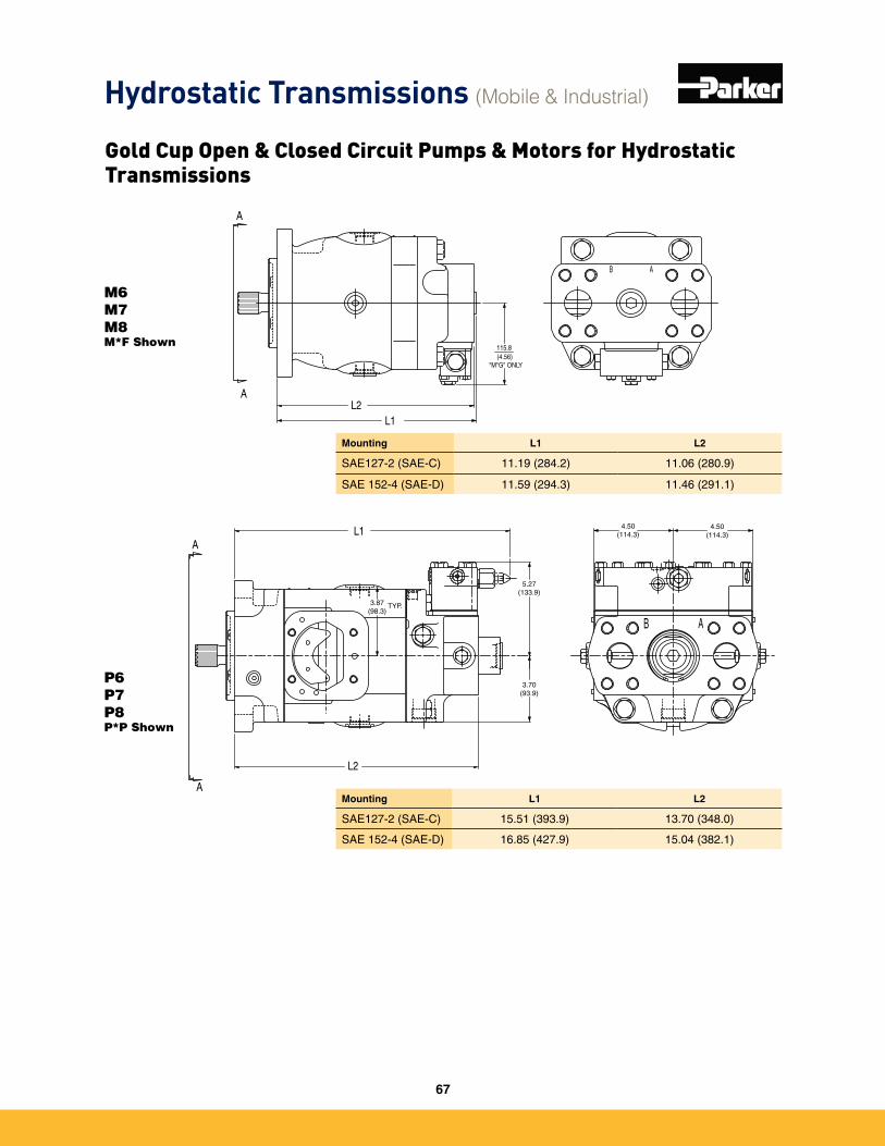
AB
L2
L1
3.87(98.3)
TYP.
5.27(133.9)
3.70(93.9)
4.50(114.3)
4.50(114.3)
"M*G" ONLY(4.56)115.8
AB
A
L1L2
A
A
AMounting L1 L2
SAE127-2 (SAE-C) 15�51 (393�9) 13�70 (348�0)
SAE 152-4 (SAE-D) 16�85 (427�9) 15�04 (382�1)
Mounting L1 L2
SAE127-2 (SAE-C) 11�19 (284�2) 11�06 (280�9)
SAE 152-4 (SAE-D) 11�59 (294�3) 11�46 (291�1)
M6M7M8M*F Shown
P6P7P8P*P Shown
Hydrostatic Transmissions (Mobile & Industrial)
Gold Cup Open & Closed Circuit Pumps & Motors for Hydrostatic Transmissions
67
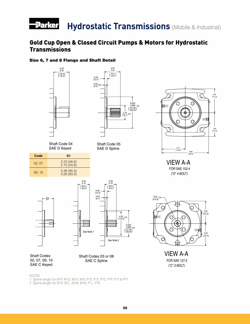
Size 6, 7 and 8 Flange and Shaft Detail
)(
DIA.
DIA.
DIA.
)DIA.
DIA.
(
0.25(6.4)
0.49(12.4)
MAX.
S1
VIEW A-A
FOR SAE 152-4("D" 4-BOLT)
("C" 2-BOLT)FOR SAE 127-2
VIEW A-A
Shaft Code 04SAE D Keyed
Shaft Code 05SAE D Spline
Shaft Codes02, 07, 09, 10SAE C Keyed
Shaft Codes 03 or 08SAE C Spline
2.97 2.9175.473.9( )
2.97 2.9175.473.9( )
2.76(70.1)
6.0005.998
152.40152.35
4.50 (114.3)
4.50 (114.3)
8.88(225.6)
4.44(112.8)
2.232.1556.6 54.6 )(
2.232.1556.6 54.6
0.49(12.4)
0.24(6.1)
4.50(114.3)
5.0004.998
127.00126.95)(
8.50(215.9)
4.22(107.2)
4.22(107.2)
See Note 1
See Note 2
NOTES1 Spline length for M*F, M*G, M*H, M*V, P*S, P*X, P*D, P*P, P*V & P*F.2 Spline length for M*R, M*L, M*M, M*N, P*L, P*R.
Code S1
02, 07 2.23 (56.6)2.15 (54.6)
09, 10 3.36 (85.3)3.28 (83.3)
Hydrostatic Transmissions (Mobile & Industrial)
Gold Cup Open & Closed Circuit Pumps & Motors for Hydrostatic Transmissions
68
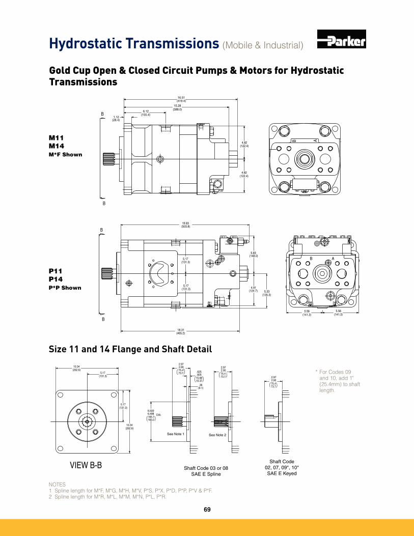
(131.3)5.17
(262.6)10.34
VIEW B-B
DIA.6.5006.498165.1165.0
75.473.7
2.972.90
.36(9.1)
2.972.9075.473.7 .625
.605
Shaft Code 03 or 08SAE E Spline
Shaft Code02, 07, 09*, 10*SAE E Keyed
(131.3)5.17
(262.6)10.34
15.8815.37
75.473.7
2.972.90
See Note 1 See Note 2
M11M14M*F Shown
P11P14P*P Shown
B A
4.91(124.7) 5.33
(135.3)
(141.3)5.56
5.17(131.3)
(148.0)5.83
(419.4)16.51
15.28(388.0)
1.12(28.4)
6.12(155.4)
4.82(122.4)
B A
4.82(122.4)
5.17(131.3)
(141.3)5.56
19.83(503.8)
18.31(465.2)
B
B
B
B
* For Codes 09 and 10, add 1" (25.4mm) to shaft length.
NOTES1 Spline length for M*F, M*G, M*H, M*V, P*S, P*X, P*D, P*P, P*V & P*F.2 Spline length for M*R, M*L, M*M, M*N, P*L, P*R.
Size 11 and 14 Flange and Shaft Detail
Hydrostatic Transmissions (Mobile & Industrial)
Gold Cup Open & Closed Circuit Pumps & Motors for Hydrostatic Transmissions
69
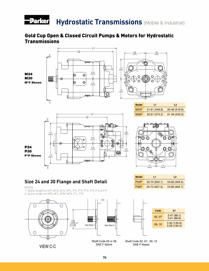
B A
C
C
(185.7) (154.4)
(157.0)6.18
(120.7)4.75
7.31 6.08
L1L2
K
G
K
TP
O
6.18(157.0)
(185.7)7.31
7.86(199.6)
L1L2
B A
6.18(157.0)
(185.7)7.31
7.86(199.6)
(185.7)7.31
(157.0)6.18
C
C
7.15(181.6)
7.15(181.6)
7.0006.998 DIA.
3.473.41
VIEW C-C
S1
Shaft Code 03 or 08SAE F Spline
Shaft Code 02, 07, 09, 10SAE F Keyed
See Note 1 See Note 2177.80 177.75( )
88.186.6( )
3.473.4188.186.6( )
0.61 (15.5)
M24M30M*F Shown
P24P30P*P Shown
Model L1 L2
P24P 23�70 (602�1) 18�08 (459�4)
P30P 24�70 (627�5) 19�08 (484�7)
Model L1 L2
M24F 21�61 (548�8) 20�46 (519�6)
M30F 22�61 (574�2) 21�46 (545�0)
Code S1
02, 07 3�47 (88�1)3�41 (86�6)
09, 10 5�35 (135�9)5�29 (134�4)
NOTES1 Spline length for M*F, M*G, M*H, M*V, P*S, P*X, P*D, P*P, P*V & P*F.2 Spline length for M*R, M*L, M*M, M*N, P*L, P*R.
Size 24 and 30 Flange and Shaft Detail
Hydrostatic Transmissions (Mobile & Industrial)
Gold Cup Open & Closed Circuit Pumps & Motors for Hydrostatic Transmissions
70
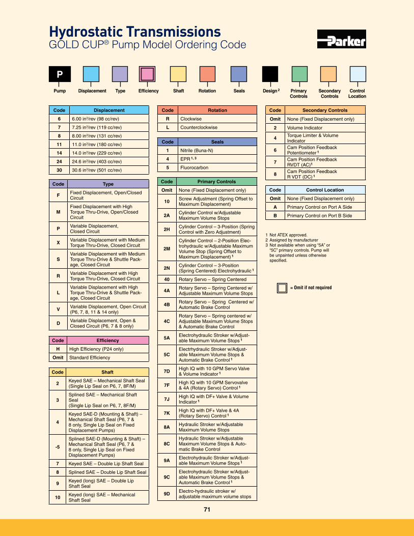
Code Shaft
2 Keyed SAE – Mechanical Shaft Seal (Single Lip Seal on P6, 7, 8F/M)
3Splined SAE – Mechanical Shaft Seal(Single Lip Seal on P6, 7, 8F/M)
4
Keyed SAE-D (Mounting & Shaft) – Mechanical Shaft Seal (P6, 7 & 8 only, Single Lip Seal on Fixed Displacement Pumps)
-5
Splined SAE-D (Mounting & Shaft) – Mechanical Shaft Seal (P6, 7 & 8 only, Single Lip Seal on Fixed Displacement Pumps)
7 Keyed SAE – Double Lip Shaft Seal
8 Splined SAE – Double Lip Shaft Seal
9 Keyed (long) SAE – Double Lip Shaft Seal
10 Keyed (long) SAE – Mechanical Shaft Seal
P
Pump
= Omit if not required
Displacement
Code Efficiency
H High Efficiency (P24 only)
Omit Standard Efficiency
Type Efficiency
Code Rotation
R Clockwise
L Counterclockwise
Code Seals
1 Nitrile (Buna-N)
4 EPR 1, 3
5 Fluorocarbon
Design 2
Code Secondary Controls
Omit None (Fixed Displacement only)
2 Volume Indicator
4 Torque Limiter & Volume Indicator
6 Cam Position Feedback Potentiometer 1
7 Cam Position Feedback RVDT (AC)1
8 Cam Position Feedback R VDT (DC) 1
Code Control Location
Omit None (Fixed Displacement only)
A Primary Control on Port A Side
B Primary Control on Port B Side
RotationShaft Seals Primary Controls
Secondary Controls
ControlLocation
1 Not ATEX approved�2 Assigned by manufacturer3 Not available when using “5A” or
“5C” primary controls� Pump will be unpainted unless otherwise specified�
Code Displacement
6 6�00 in3/rev (98 cc/rev)
7 7�25 in3/rev (119 cc/rev)
8 8�00 in3/rev (131 cc/rev)
11 11�0 in3/rev (180 cc/rev)
14 14�0 in3/rev (229 cc/rev)
24 24�6 in3/rev (403 cc/rev)
30 30�6 in3/rev (501 cc/rev)
Code Type
F Fixed Displacement, Open/Closed Circuit
MFixed Displacement with High Torque Thru-Drive, Open/Closed Circuit
P Variable Displacement, Closed Circuit
X Variable Displacement with Medium Torque Thru-Drive, Closed Circuit
SVariable Displacement with Medium Torque Thru-Drive & Shuttle Pack-age, Closed Circuit
R Variable Displacement with High Torque Thru-Drive, Closed Circuit
LVariable Displacement with High Torque Thru-Drive & Shuttle Pack-age, Closed Circuit
V Variable Displacement, Open Circuit (P6, 7, 8, 11 & 14 only)
D Variable Displacement, Open & Closed Circuit (P6, 7 & 8 only)
Code Primary Controls
Omit None (Fixed Displacement only)
10 Screw Adjustment (Spring Offset to Maximum Displacement)
2A Cylinder Control w/Adjustable Maximum Volume Stops
2H Cylinder Control – 3-Position (Spring Control with Zero Adjustment)
2M
Cylinder Control – 2-Position Elec-trohydraulic w/Adjustable Maximum Volume Stop (Spring Offset to Maximum Displacement) 1
2N Cylinder Control – 3-Position (Spring Centered) Electrohydraulic 1
40 Rotary Servo – Spring Centered
4A Rotary Servo – Spring Centered w/Adjustable Maximum Volume Stops
4B Rotary Servo – Spring Centered w/Automatic Brake Control
4CRotary Servo – Spring centered w/Adjustable Maximum Volume Stops
& Automatic Brake Control
5A Electrohydraulic Stroker w/Adjust-able Maximum Volume Stops 1
5CElectrhydraulic Stroker w/Adjust-able Maximum Volume Stops & Automatic Brake Control 1
7D High IQ with 10 GPM Servo Valve & Volume Indicator 1
7F High IQ with 10 GPM Servovalve & 4A (Rotary Servo) Control 1
7J High IQ with DF+ Valve & Volume Indicator 1
7K High IQ with DF+ Valve & 4A (Rotary Servo) Control 1
8A Hydraulic Stroker w/Adjustable Maximum Volume Stops
8CHydraulic Stroker w/Adjustable Maximum Volume Stops & Auto-matic Brake Control
9A Electrohydraulic Stroker w/Adjust-able Maximum Volume Stops 1
9CElectrohydraulic Stroker w/Adjust-able Maximum Volume Stops & Automatic Brake Control 1
9D Electro-hydraulic stroker w/ adjustable maximum volume stops
Hydrostatic Transmissions GOLD CUP® Pump Model Ordering Code
71
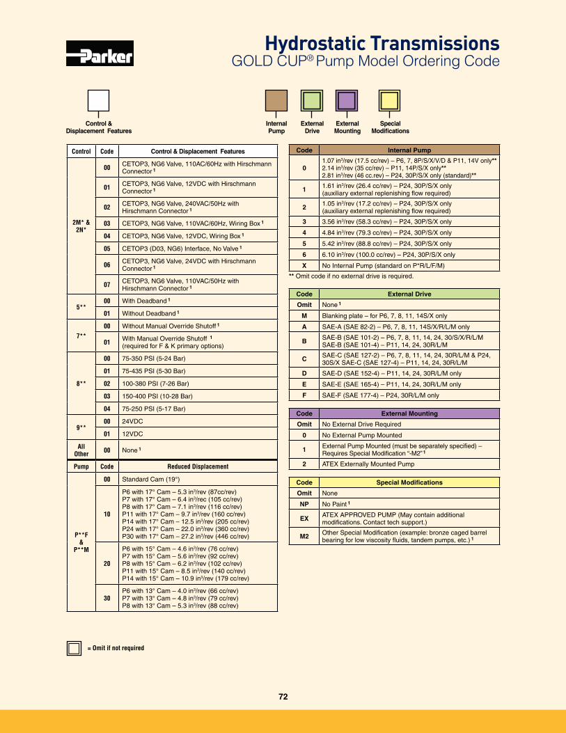
Control &Displacement Features
= Omit if not required
Code Internal Pump
01�07 in3/rev (17�5 cc/rev) – P6, 7, 8P/S/X/V/D & P11, 14V only** 2�14 in3/rev (35 cc/rev) – P11, 14P/S/X only**
2�81 in3/rev (46 cc�rev) – P24, 30P/S/X only (standard)**
1 1�61 in3/rev (26�4 cc/rev) – P24, 30P/S/X only(auxiliary external replenishing flow required)
2 1�05 in3/rev (17�2 cc/rev) – P24, 30P/S/X only(auxiliary external replenishing flow required)
3 3�56 in3/rev (58�3 cc/rev) – P24, 30P/S/X only
4 4�84 in3/rev (79�3 cc/rev) – P24, 30P/S/X only
5 5�42 in3/rev (88�8 cc/rev) – P24, 30P/S/X only
6 6�10 in3/rev (100�0 cc/rev) – P24, 30P/S/X only
X No Internal Pump (standard on P*R/L/F/M)
** Omit code if no external drive is required�
Code External Drive
Omit None 1
M Blanking plate – for P6, 7, 8, 11, 14S/X only
A SAE-A (SAE 82-2) – P6, 7, 8, 11, 14S/X/R/L/M only
B SAE-B (SAE 101-2) – P6, 7, 8, 11, 14, 24, 30/S/X/R/L/MSAE-B (SAE 101-4) – P11, 14, 24, 30R/L/M
C SAE-C (SAE 127-2) – P6, 7, 8, 11, 14, 24, 30R/L/M & P24, 30S/X SAE-C (SAE 127-4) – P11, 14, 24, 30R/L/M
D SAE-D (SAE 152-4) – P11, 14, 24, 30R/L/M only
E SAE-E (SAE 165-4) – P11, 14, 24, 30R/L/M only
F SAE-F (SAE 177-4) – P24, 30R/L/M only
Code External Mounting
Omit No External Drive Required
0 No External Pump Mounted
1 External Pump Mounted (must be separately specified) – Requires Special Modification “-M2” 1
2 ATEX Externally Mounted Pump
Code Special Modifications
Omit None
NP No Paint 1
EX ATEX APPROVED PUMP (May contain additional modifications� Contact tech support�)
M2 Other Special Modification (example: bronze caged barrel bearing for low viscosity fluids, tandem pumps, etc�) 1
ExternalDrive
External Mounting
Special Modifications
Control Code Control & Displacement Features
2M* & 2N*
00 CETOP3, NG6 Valve, 110AC/60Hz with Hirschmann Connector 1
01 CETOP3, NG6 Valve, 12VDC with Hirschmann Connector 1
02 CETOP3, NG6 Valve, 240VAC/50Hz with Hirschmann Connector 1
03 CETOP3, NG6 Valve, 110VAC/60Hz, Wiring Box 1
04 CETOP3, NG6 Valve, 12VDC, Wiring Box 1
05 CETOP3 (D03, NG6) Interface, No Valve 1
06 CETOP3, NG6 Valve, 24VDC with Hirschmann Connector 1
07 CETOP3, NG6 Valve, 110VAC/50Hz with Hirschmann Connector 1
5**00 With Deadband 1
01 Without Deadband 1
7**00 Without Manual Override Shutoff 1
01 With Manual Override Shutoff 1
(required for F & K primary options)
8**
00 75-350 PSI (5-24 Bar)
01 75-435 PSI (5-30 Bar)
02 100-380 PSI (7-26 Bar)
03 150-400 PSI (10-28 Bar)
04 75-250 PSI (5-17 Bar)
9**00 24VDC
01 12VDC
All Other 00 None 1
Pump Code Reduced Displacement
P**F &
P**M
00 Standard Cam (19°)
10
P6 with 17° Cam – 5�3 in3/rev (87cc/rev)
P7 with 17° Cam – 6�4 in3/rec (105 cc/rev)P8 with 17° Cam – 7�1 in3/rev (116 cc/rev)P11 with 17° Cam – 9�7 in3/rev (160 cc/rev)P14 with 17° Cam – 12�5 in3/rev (205 cc/rev)P24 with 17° Cam – 22�0 in3/rev (360 cc/rev)P30 with 17° Cam – 27�2 in3/rev (446 cc/rev)
20
P6 with 15° Cam – 4�6 in3/rev (76 cc/rev)P7 with 15° Cam – 5�6 in3/rev (92 cc/rev)P8 with 15° Cam – 6�2 in3/rev (102 cc/rev)P11 with 15° Cam – 8�5 in3/rev (140 cc/rev)P14 with 15° Cam – 10�9 in3/rev (179 cc/rev)
30P6 with 13° Cam – 4�0 in3/rev (66 cc/rev)P7 with 13° Cam – 4�8 in3/rev (79 cc/rev)P8 with 13° Cam – 5�3 in3/rev (88 cc/rev)
InternalPump
Hydrostatic Transmissions GOLD CUP® Pump Model Ordering Code
72
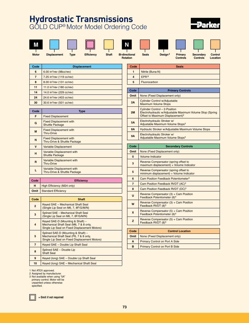
Code Shaft
2 Keyed SAE – Mechanical Shaft Seal (Single Lip Seal on M6, 7, 8F/G/M/N)
3 Splined SAE – Mechanical Shaft Seal(Single Lip Seal on M6, 7, 8F/G/M/N)
4Keyed SAE-D (Mounting & Shaft) – Mechanical Shaft Seal (M6, 7 & 8 only, Single Lip Seal on Fixed Displacement Motors)
5Splined SAE-D (Mounting & Shaft) – Mechanical Shaft Seal (P6, 7 & 8 only, Single Lip Seal on Fixed Displacement Motors)
7 Keyed SAE – Double Lip Shaft Seal
8 Splined SAE – Double Lip Shaft Seal
9 Keyed (long) SAE – Double Lip Shaft Seal
10 Keyed (long) SAE – Mechanical Shaft Seal
NM
Code Displacement
6 6�00 in3/rev (98cc/rev)
7 7�25 in3/rev (119 cc/rev)
8 8�00 in3/rev (131 cc/rev)
11 11�0 in3/rev (180 cc/rev)
14 14�0 in3/rev (229 cc/rev)
24 24�6 in3/rev (403 cc/rev)
30 30�6 in3/rev (501 cc/rev)
Motor
Code Type
F Fixed Displacement
G Fixed Displacement with Shuttle Package
M Fixed Displacement with Thru-Drive
N Fixed Displacement with Thru-Drive & Shuttle Package
V Variable Displacement
H Variable Displacement with Shuttle Package
R Variable Displacement with Thru-Drive
L Variable Displacement with Thru-Drive & Shuttle Package
= Omit if not required
Displacement
Code Efficiency
H High Efficiency (M24 only)
Omit Standard Efficiency
Type
Code Seals
1 Nitrile (Buna-N)
4 EPR 3
5 Fluorocarbon
Design 2
Code Primary Controls
Omit None (Fixed Displacement only)
2A Cylinder Control w/Adjustable Maximum Volume Stops
2MCylinder Control – 2-Position Electrohydraulic w/Adjustable Maximum Volume Stop (Spring Offset to Maximum Displacement)1
5A Electrohydraulic Stroker w/ Adjustable Maximum Volume Stops1
8A Hydraulic Stroker w/Adjustable Maximum Volume Stops
9A Electrohydraulic Stroker w/ Adjustable Maximum Volume Stops1
Code Secondary Controls
Omit None (Fixed Displacement only)
0 Volume Indicator
3 Reverse Compensator (spring offset to maximum displacement) + Volume Indicator
5 Reverse Compensator (spring offset to minimum displacement) + Volume Indicator
6 Cam Position Feedback Potentiometer1
7 Cam Position Feedback RVDT (AC)1
8 Cam Position Feedback RVDT (DC)1
U Reverse Compensator (3) + Cam Position Feedback Potentiometer (6)1
W Reverse Compensator (3) + Cam Position Feedback RVDT (8)1
X Reverse Compensator (5) + Cam Position Feedback Potentiometer (6)1
Z Reverse Compensator (5) + Cam Position Feedback RVDT (8)1
Code Control Location
Omit None (Fixed Displacement only)
A Primary Control on Port A Side
B Primary Control on Port B Side
Bi-directionalRotation
Shaft Seals Primary Controls
Secondary Controls
ControlLocation
1 Not ATEX approved�2 Assigned by manufacturer�3 Not available when using “5A”
primary control� Motor will be unpainted unless otherwise specified�
Efficiency
Hydrostatic Transmissions GOLD CUP® Motor Model Ordering Code
73
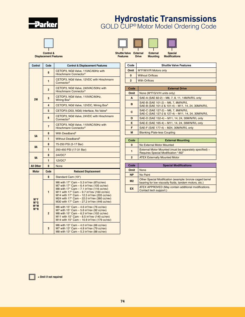
Control &Displacement Features
= Omit if not required
Code External Drive
Omit None (M*F/G/V/H units only)
A SAE-A (SAE 82-2) – M6, 7, 8, 11, 14M/N/R/L only
B SAE-B (SAE 101-2) – M6, 7, 8M/N/R/L SAE-B (SAE 101-2 & 101-4) – M11, 14, 24, 30M/N/R/L
C SAE-C (SAE 127-2) – M6, 7, 8M/N/R/LSAE-C (SAE 127-2 & 127-4) – M11, 14, 24, 30M/N/R/L
D SAE-D (SAE 152-4) – M11, 14, 24, 30M/N/R/L only
E SAE-E (SAE 165-4) – M11, 14, 24, 30M/N/R/L only
F SAE-F (SAE 177-4) – M24, 30M/N/R/L only
M Blanking Plate-less Coupling
Code External Mounting
0 No External Motor Mounted
1 External Motor Mounted (must be separately specified) – Requires Special Modification “-M2”
2 ATEX Externally Mounted Motor
Code Special Modifications
Omit None
NP No Paint
M2 Other Special Modification (example: bronze caged barrel bearing for low viscosity fluids, tandem motors, etc�)
EX ATEX APPROVED (May contain additional modifications� Contact tech support�)
ExternalDrive
External Mounting
Special Modifications
Control Code Control & Displacement Features
2M
0 CETOP3, NG6 Valve, 110AC/60Hz with Hirschmann Connector1
1 CETOP3, NG6 Valve, 12VDC with Hirschmann Connector1
2 CETOP3, NG6 Valve, 240VAC/50Hz with Hirschmann Connector1
3 CETOP3, NG6 Valve, 110VAC/60Hz, Wiring Box1
4 CETOP3, NG6 Valve, 12VDC, Wiring Box1
5 CETOP3 (D03, NG6) Interface, No Valve1
6 CETOP3, NG6 Valve, 24VDC with Hirschmann Connector1
7 CETOP3, NG6 Valve, 110VAC/50Hz with Hirschmann Connector1
5A0 With Deadband1
1 Without Deadband1
8A0 75-250 PSI (5-17 Bar)
1 250-450 PSI (17-31 Bar)
9A0 24VDC1
1 12VDC1
All Other 0 None
Motor Code Reduced Displacement
M*F M*GM*MM*N
0 Standard Cam (19°)
1
M6 with 17° Cam – 5�3 in3/rev (87cc/rev)M7 with 17° Cam – 6�4 in3/rec (105 cc/rev)M8 with 17° Cam – 7�1 in3/rev (116 cc/rev)M11 with 17° Cam – 9�7 in3/rev (160 cc/rev)M14 with 17° Cam – 12�5 in3/rev (205 cc/rev)M24 with 17° Cam – 22�0 in3/rev (360 cc/rev)M30 with 17° Cam – 27�2 in3/rev (446 cc/rev)
2
M6 with 15° Cam – 4�6 in3/rev (76 cc/rev)M7 with 15° Cam – 5�6 in3/rev (92 cc/rev)M8 with 15° Cam – 6�2 in3/rev (102 cc/rev)M11 with 15° Cam – 8�5 in3/rev (140 cc/rev)M14 with 15° Cam – 10�9 in3/rev (179 cc/rev)
3M6 with 13° Cam – 4�0 in3/rev (66 cc/rev)M7 with 13° Cam – 4�8 in3/rev (79 cc/rev)M8 with 13° Cam – 5�3 in3/rev (88 cc/rev)
Shuttle Valve Features
Code Shuttle Valve Features
Omit M*F/M/V/R Motors only
0 Without Orifices
2 With Orifices
Hydrostatic Transmissions GOLD CUP® Motor Model Ordering Code
74

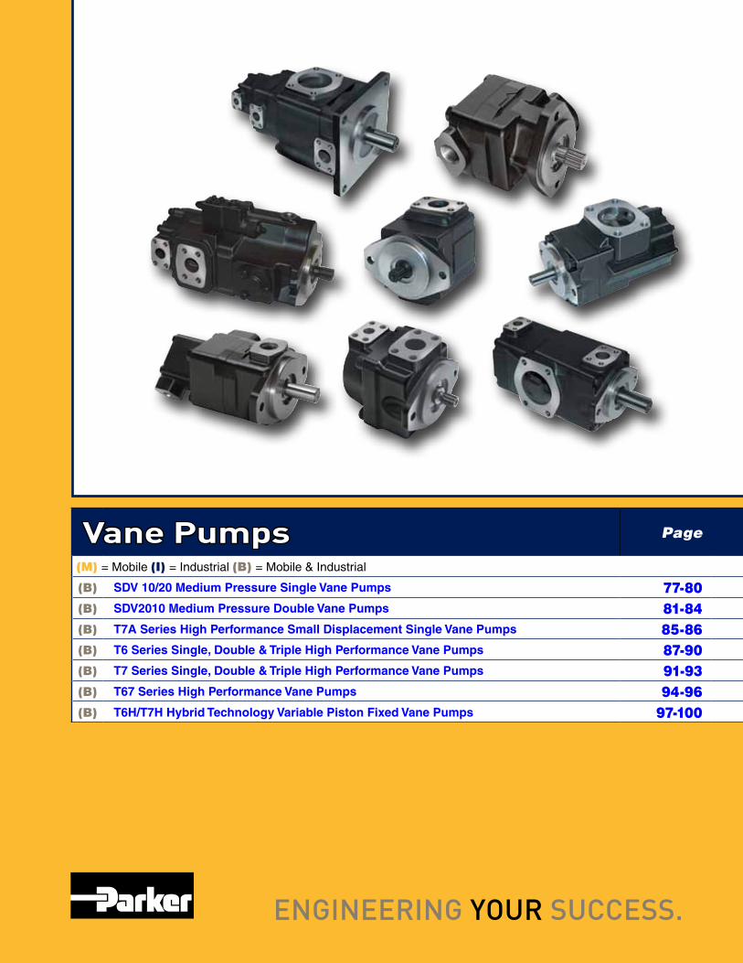
Vane Pumps Page
(M) = Mobile (I) = Industrial (B) = Mobile & Industrial
(B) SDV 10/20 Medium Pressure Single Vane Pumps 77-80(B) SDV2010 Medium Pressure Double Vane Pumps 81-84(B) T7A Series High Performance Small Displacement Single Vane Pumps 85-86(B) T6 Series Single, Double & Triple High Performance Vane Pumps 87-90(B) T7 Series Single, Double & Triple High Performance Vane Pumps 91-93(B) T67 Series High Performance Vane Pumps 94-96(B) T6H/T7H Hybrid Technology Variable Piston Fixed Vane Pumps 97-100
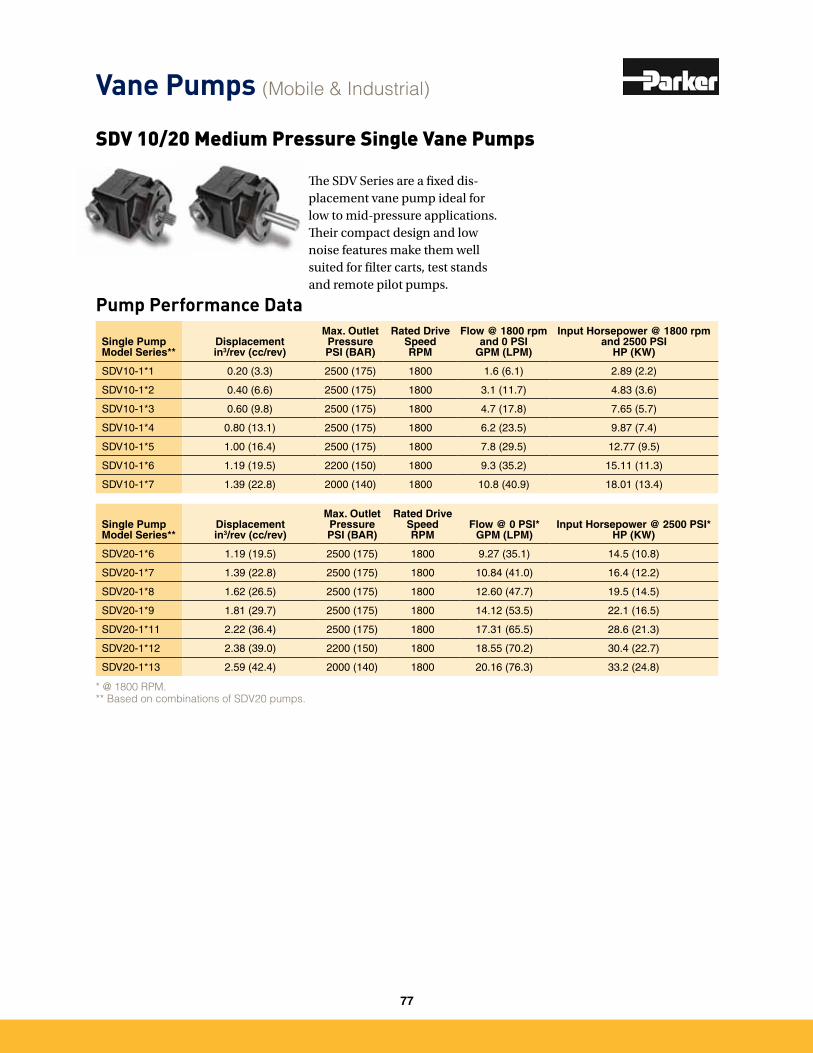
Vane Pumps (Mobile & Industrial)
Pump Performance Data
SDV 10/20 Medium Pressure Single Vane Pumps
The SDV Series are a fixed dis-placement vane pump ideal for low to mid-pressure applications. Their compact design and low noise features make them well suited for filter carts, test stands and remote pilot pumps.
Single Pump Model Series**
Displacementin3/rev (cc/rev)
Max. Outlet PressurePSI (BAR)
Rated Drive SpeedRPM
Flow @ 1800 rpm and 0 PSI
GPM (LPM)
Input Horsepower @ 1800 rpm and 2500 PSI
HP (KW)
SDV10-1*1 0�20 (3�3) 2500 (175) 1800 1�6 (6�1) 2�89 (2�2)
SDV10-1*2 0�40 (6�6) 2500 (175) 1800 3�1 (11�7) 4�83 (3�6)
SDV10-1*3 0�60 (9�8) 2500 (175) 1800 4�7 (17�8) 7�65 (5�7)
SDV10-1*4 0�80 (13�1) 2500 (175) 1800 6�2 (23�5) 9�87 (7�4)
SDV10-1*5 1�00 (16�4) 2500 (175) 1800 7�8 (29�5) 12�77 (9�5)
SDV10-1*6 1�19 (19�5) 2200 (150) 1800 9�3 (35�2) 15�11 (11�3)
SDV10-1*7 1�39 (22�8) 2000 (140) 1800 10�8 (40�9) 18�01 (13�4)
Single Pump Model Series**
Displacementin3/rev (cc/rev)
Max. Outlet PressurePSI (BAR)
Rated Drive SpeedRPM
Flow @ 0 PSI*GPM (LPM)
Input Horsepower @ 2500 PSI*HP (KW)
SDV20-1*6 1�19 (19�5) 2500 (175) 1800 9�27 (35�1) 14�5 (10�8)
SDV20-1*7 1�39 (22�8) 2500 (175) 1800 10�84 (41�0) 16�4 (12�2)
SDV20-1*8 1�62 (26�5) 2500 (175) 1800 12�60 (47�7) 19�5 (14�5)
SDV20-1*9 1�81 (29�7) 2500 (175) 1800 14�12 (53�5) 22�1 (16�5)
SDV20-1*11 2�22 (36�4) 2500 (175) 1800 17�31 (65�5) 28�6 (21�3)
SDV20-1*12 2�38 (39�0) 2200 (150) 1800 18�55 (70�2) 30�4 (22�7)
SDV20-1*13 2�59 (42�4) 2000 (140) 1800 20�16 (76�3) 33�2 (24�8)
* @ 1800 RPM.** Based on combinations of SDV20 pumps.
77
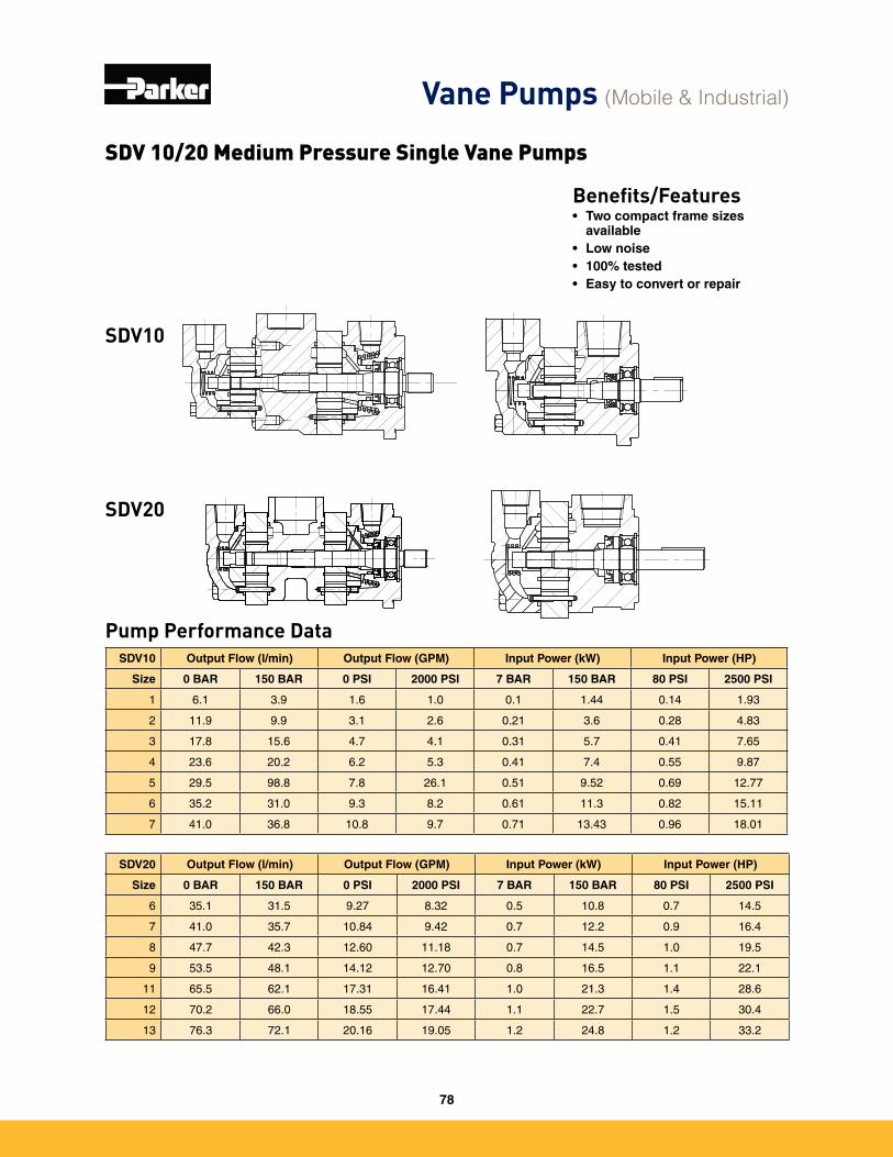
Vane Pumps (Mobile & Industrial)
Pump Performance Data
Benefits/Features• Two compact frame sizes
available• Low noise• 100% tested• Easy to convert or repair
SDV10
SDV20
SDV20 Output Flow (l/min) Output Flow (GPM) Input Power (kW) Input Power (HP)
Size 0 BAR 150 BAR 0 PSI 2000 PSI 7 BAR 150 BAR 80 PSI 2500 PSI
6 35�1 31�5 9�27 8�32 0�5 10�8 0�7 14�5
7 41�0 35�7 10�84 9�42 0�7 12�2 0�9 16�4
8 47�7 42�3 12�60 11�18 0�7 14�5 1�0 19�5
9 53�5 48�1 14�12 12�70 0�8 16�5 1�1 22�1
11 65�5 62�1 17�31 16�41 1�0 21�3 1�4 28�6
12 70�2 66�0 18�55 17�44 1�1 22�7 1�5 30�4
13 76�3 72�1 20�16 19�05 1�2 24�8 1�2 33�2
SDV10 Output Flow (l/min) Output Flow (GPM) Input Power (kW) Input Power (HP)
Size 0 BAR 150 BAR 0 PSI 2000 PSI 7 BAR 150 BAR 80 PSI 2500 PSI
1 6�1 3�9 1�6 1�0 0�1 1�44 0�14 1�93
2 11�9 9�9 3�1 2�6 0�21 3�6 0�28 4�83
3 17�8 15�6 4�7 4�1 0�31 5�7 0�41 7�65
4 23�6 20�2 6�2 5�3 0�41 7�4 0�55 9�87
5 29�5 98�8 7�8 26�1 0�51 9�52 0�69 12�77
6 35�2 31�0 9�3 8�2 0�61 11�3 0�82 15�11
7 41�0 36�8 10�8 9�7 0�71 13�43 0�96 18�01
SDV 10/20 Medium Pressure Single Vane Pumps
78
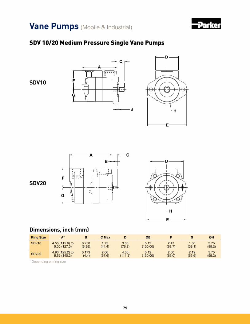
Ring Size A* B C Max D ØE F G ØH
SDV10 4�55 (115�6) to 5�00 (127�0)
0�250 (6�35)
1�75(44�4)
3�00 (76�2)
5�12 (130�00)
2�47(62�7)
1�50(38�1)
3�75(95�2)
SDV20 4�93 (125�2) to 5�52 (140�2)
0�173 (4�4)
2�66(67�6)
4�38 (111�2)
5�12 (130�00)
2�60 (66�0)
2�19 (55�6)
3�75(95�2)
* Depending on ring size
Dimensions, inch (mm)
H
A
B
CD
F
E
G
A
B
C
D
E
F
G
H
SDV10
SDV20
Vane Pumps (Mobile & Industrial)
SDV 10/20 Medium Pressure Single Vane Pumps
79
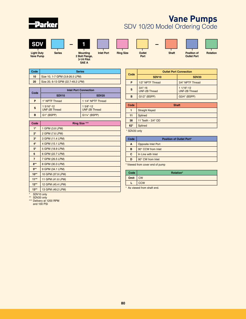
SDV 1
Code Rotation*
Omit CW
L CCW
* As viewed from shaft end�
Code Series
10 Size 10, 1-7 GPM (3�8-26�5 LPM)
20 Size 20, 6-13 GPM (22�7-49�2 LPM)
* SDV10 only** SDV20 only*** Delivery at 1200 RPM
and 100 PSI
Code Shaft
1 Straight Keyed
11 Splined
38 11 Teeth - 3/4" OD
62* Splined
SeriesLight DutyVane Pump
Mounting 2 Bolt Flange,
3-1/4 Pilot SAE A
RotationRing Size Outlet Port
ShaftInlet Port
– –
CodeInlet Port Connection
SDV10 SDV20
P 1" NPTF Thread 1 1/4" NPTF Thread
S 1 5/16"-12 UNF-2B Thread
1 5/8"-12 UNF-2B Thread
B G1" (BSPP) G1¼" (BSPP)
Code Ring Size ***
1* 1 GPM (3�8 LPM)
2* 2 GPM (7�6 LPM)
3* 3 GPM (11�4 LPM)
4* 4 GPM (15�1 LPM)
5* 5 GPM (18�9 LPM)
6 6 GPM (22�7 LPM)
7 7 GPM (26�5 LPM)
8** 8 GPM (30�3 LPM)
9** 9 GPM (34�1 LPM)
10** 10 GPM (37�9 LPM)
11** 11 GPM (41�6 LPM)
12** 12 GPM (45�4 LPM)
13** 13 GPM (49�2 LPM)
CodeOutlet Port Connection
SDV10 SDV20
P 1/2" NPTF Thread 3/4" NPTF Thread
S 3/4"-16 UNF-2B Thread
1 1/16"-12 UNF-2B Thread
B G1/2" (BSPP) G3/4" (BSPP)
* SDV20 only
* Viewed from cover end of pump
Code Position of Outlet Port*
A Opposite Inlet Port
B 90° CCW from Inlet
C In Line with Inlet
D 90° CW from Inlet
Vane Pumps SDV 10/20 Model Ordering Code
Position of Outlet Port
80
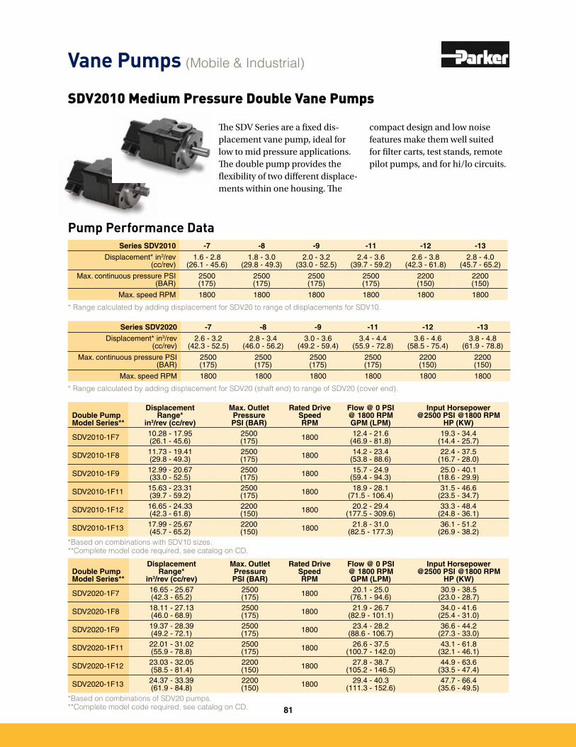
Pump Performance Data
SDV2010 Medium Pressure Double Vane Pumps
The SDV Series are a fixed dis-placement vane pump, ideal for low to mid pressure applications. The double pump provides the flexibility of two different displace-ments within one housing. The
compact design and low noise features make them well suited for filter carts, test stands, remote pilot pumps, and for hi/lo circuits.
Series SDV2020 -7 -8 -9 -11 -12 -13
Displacement* in3/rev(cc/rev)
2�6 - 3�2(42�3 - 52�5)
2�8 - 3�4(46�0 - 56�2)
3�0 - 3�6(49�2 - 59�4)
3�4 - 4�4(55�9 - 72�8)
3�6 - 4�6(58�5 - 75�4)
3�8 - 4�8(61�9 - 78�8)
Max� continuous pressure PSI(BAR)
2500(175)
2500(175)
2500(175)
2500(175)
2200(150)
2200(150)
Max� speed RPM 1800 1800 1800 1800 1800 1800
* Range calculated by adding displacement for SDV20 (shaft end) to range of SDV20 (cover end).
Series SDV2010 -7 -8 -9 -11 -12 -13
Displacement* in3/rev(cc/rev)
1�6 - 2�8(26�1 - 45�6)
1�8 - 3�0(29�8 - 49�3)
2�0 - 3�2(33�0 - 52�5)
2�4 - 3�6(39�7 - 59�2)
2�6 - 3�8(42�3 - 61�8)
2�8 - 4�0(45�7 - 65�2)
Max� continuous pressure PSI(BAR)
2500(175)
2500(175)
2500(175)
2500(175)
2200(150)
2200(150)
Max� speed RPM 1800 1800 1800 1800 1800 1800
* Range calculated by adding displacement for SDV20 to range of displacements for SDV10.
Double Pump Model Series**
Displacement Range*
in3/rev (cc/rev)
Max. Outlet Pressure PSI (BAR)
Rated Drive Speed RPM
Flow @ 0 PSI @ 1800 RPMGPM (LPM)
Input Horsepower @2500 PSI @1800 RPM
HP (KW)
SDV2020-1F7 16�65 - 25�67(42�3 - 65�2)
2500(175) 1800 20�1 - 25�0
(76�1 - 94�6)30�9 - 38�5
(23�0 - 28�7)
SDV2020-1F8 18�11 - 27�13(46�0 - 68�9)
2500(175) 1800 21�9 - 26�7
(82�9 - 101�1)34�0 - 41�6
(25�4 - 31�0)
SDV2020-1F9 19�37 - 28�39(49�2 - 72�1)
2500(175) 1800 23�4 - 28�2
(88�6 - 106�7)36�6 - 44�2
(27�3 - 33�0)
SDV2020-1F11 22�01 - 31�02(55�9 - 78�8)
2500(175) 1800 26�6 - 37�5
(100�7 - 142�0)43�1 - 61�8
(32�1 - 46�1)
SDV2020-1F12 23�03 - 32�05(58�5 - 81�4)
2200(150) 1800 27�8 - 38�7
(105�2 - 146�5)44�9 - 63�6
(33�5 - 47�4)
SDV2020-1F13 24�37 - 33�39(61�9 - 84�8)
2200(150) 1800 29�4 - 40�3
(111�3 - 152�6)47�7 - 66�4
(35�6 - 49�5)*Based on combinations of SDV20 pumps.**Complete model code required, see catalog on CD.
Double Pump Model Series**
Displacement Range*
in3/rev (cc/rev)
Max. Outlet Pressure PSI (BAR)
Rated Drive Speed RPM
Flow @ 0 PSI @ 1800 RPMGPM (LPM)
Input Horsepower @2500 PSI @1800 RPM
HP (KW)
SDV2010-1F7 10�28 - 17�95 (26�1 - 45�6)
2500(175) 1800 12�4 - 21�6
(46�9 - 81�8)19�3 - 34�4
(14�4 - 25�7)
SDV2010-1F8 11�73 - 19�41(29�8 - 49�3)
2500(175) 1800 14�2 - 23�4
(53�8 - 88�6)22�4 - 37�5
(16�7 - 28�0)
SDV2010-1F9 12�99 - 20�67(33�0 - 52�5)
2500(175) 1800 15�7 - 24�9
(59�4 - 94�3)25�0 - 40�1
(18�6 - 29�9)
SDV2010-1F11 15�63 - 23�31(39�7 - 59�2)
2500(175) 1800 18�9 - 28�1
(71�5 - 106�4)31�5 - 46�6
(23�5 - 34�7)
SDV2010-1F12 16�65 - 24�33(42�3 - 61�8)
2200(150) 1800 20�2 - 29�4
(177�5 - 309�6)33�3 - 48�4
(24�8 - 36�1)
SDV2010-1F13 17�99 - 25�67(45�7 - 65�2)
2200(150) 1800 21�8 - 31�0
(82�5 - 177�3)36�1 - 51�2
(26�9 - 38�2)*Based on combinations with SDV10 sizes.**Complete model code required, see catalog on CD.
Vane Pumps (Mobile & Industrial)
81
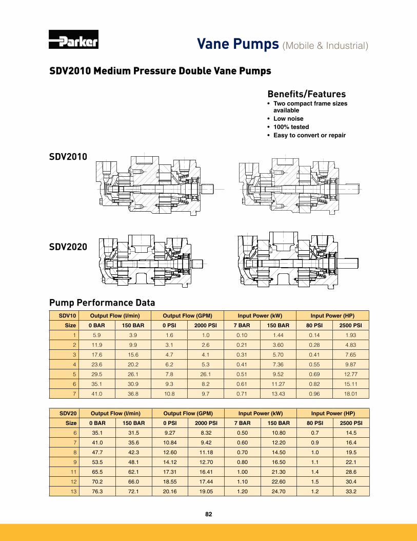
Pump Performance Data
SDV2020
SDV2010
Benefits/Features• Two compact frame sizes
available• Low noise• 100% tested• Easy to convert or repair
SDV10 Output Flow (l/min) Output Flow (GPM) Input Power (kW) Input Power (HP)
Size 0 BAR 150 BAR 0 PSI 2000 PSI 7 BAR 150 BAR 80 PSI 2500 PSI
1 5.9 3.9 1.6 1.0 0.10 1.44 0.14 1.93
2 11.9 9.9 3.1 2.6 0.21 3.60 0.28 4.83
3 17.6 15.6 4.7 4.1 0.31 5.70 0.41 7.65
4 23.6 20.2 6.2 5.3 0.41 7.36 0.55 9.87
5 29.5 26.1 7.8 26.1 0.51 9.52 0.69 12.77
6 35.1 30.9 9.3 8.2 0.61 11.27 0.82 15.11
7 41.0 36.8 10.8 9.7 0.71 13.43 0.96 18.01
SDV20 Output Flow (l/min) Output Flow (GPM) Input Power (kW) Input Power (HP)
Size 0 BAR 150 BAR 0 PSI 2000 PSI 7 BAR 150 BAR 80 PSI 2500 PSI
6 35�1 31�5 9�27 8�32 0�50 10�80 0�7 14�5
7 41�0 35�6 10�84 9�42 0�60 12�20 0�9 16�4
8 47�7 42�3 12�60 11�18 0�70 14�50 1�0 19�5
9 53�5 48�1 14�12 12�70 0�80 16�50 1�1 22�1
11 65�5 62�1 17�31 16�41 1�00 21�30 1�4 28�6
12 70�2 66�0 18�55 17�44 1�10 22�60 1�5 30�4
13 76�3 72�1 20�16 19�05 1�20 24�70 1�2 33�2
SDV2010 Medium Pressure Double Vane Pumps
Vane Pumps (Mobile & Industrial)
82
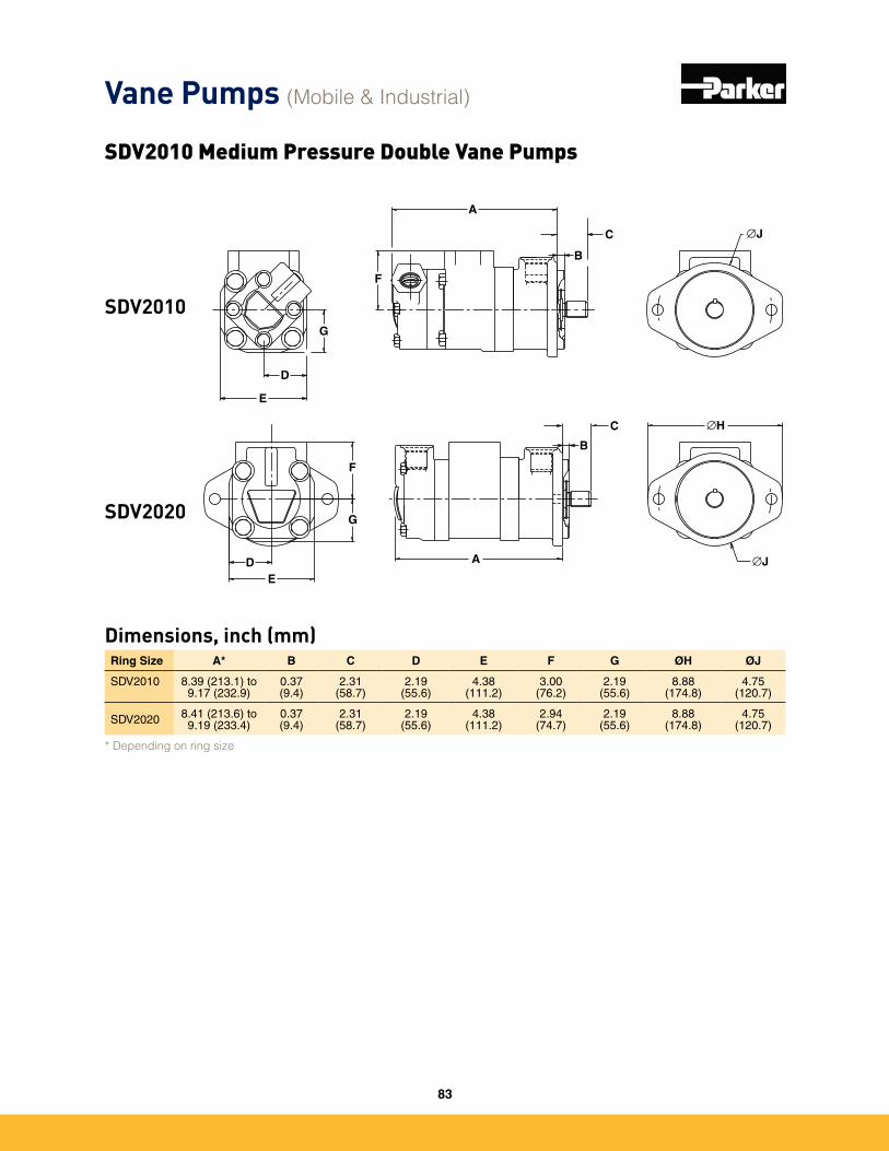
Ring Size A* B C D E F G ØH ØJ
SDV2010 8�39 (213�1) to 9�17 (232�9)
0�37(9�4)
2�31(58�7)
2�19(55�6)
4�38(111�2)
3�00(76�2)
2�19(55�6)
8�88(174�8)
4�75(120�7)
SDV2020 8�41 (213�6) to 9�19 (233�4)
0�37 (9�4)
2�31(58�7)
2�19(55�6)
4�38(111�2)
2�94(74�7)
2�19(55�6)
8�88(174�8)
4�75(120�7)
* Depending on ring size
Dimensions, inch (mm)
A
B
C
D
E
F
G
∅J
C
B
A ∅JDE
F
G
∅H
SDV2020
SDV2010
Vane Pumps (Mobile & Industrial)
SDV2010 Medium Pressure Double Vane Pumps
83
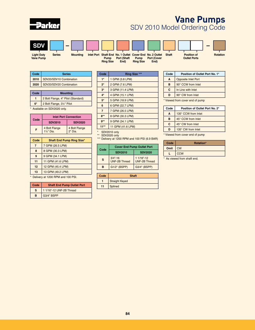
SDV
Code Mounting
1 2 Bolt Flange, 4" Pilot (Standard)
6* 2 Bolt Flange, 3¼" Pilot
Code Rotation*
Omit CW
L CCW
* As viewed from shaft end�
Code Series
2010 SDV20/SDV10 Combination
2020 SDV20/SDV20 Combination
* SDV2010 only** SDV2020 only*** Delivery at 1200 RPM and 100 PSI (6�9 BAR)
Code Shaft
1 Straight Keyed
11 Splined
SeriesLight DutyVane Pump
Mounting RotationShaft End Pump
Ring Size
No. 1 Outlet Port (Shaft
End)
ShaftInlet Port
–
CodeInlet Port Connection
SDV2010 SDV2020
F 4 Bolt Flange1½" Dia�
4 Bolt Flange 2" Dia�
Code Ring Size ***
1* 1 GPM (3�8 LPM)
2* 2 GPM (7�6 LPM)
3* 3 GPM (11�4 LPM)
4* 4 GPM (15�1 LPM)
5* 5 GPM (18�9 LPM)
6 6 GPM (22�7 LPM)
7 7 GPM (26�5 LPM)
8** 8 GPM (30�3 LPM)
9** 9 GPM (34�1 LPM)
11** 11 GPM (41�6 LPM)
CodeCover End Pump Outlet Port
SDV2010 SDV2020
S 3/4"-16 UNF-2B Thread
1 1/16"-12 UNF-2B Thread
B G1/2" (BSPP) G3/4" (BSPP)
* Viewed from cover end of pump
Code Position of Outlet Port No. 1*
A Opposite Inlet Port
B 90° CCW from Inlet
C In Line with Inlet
D 90° CW from Inlet
* Available on SDV2020 only�
Code Shaft End Pump Ring Size*
7 7 GPM (26�5 LPM)
8 8 GPM (30�3 LPM)
9 9 GPM (34�1 LPM)
11 11 GPM (41�6 LPM)
12 12 GPM (45�4 LPM)
13 13 GPM (49�2 LPM)
Code Shaft End Pump Outlet Port
S 1 1/16"-12 UNF-2B Thread
B G3/4" BSPP
Cover End Pump
Ring Size
No. 2 Outlet Port (Cover
End)
–
* Viewed from cover end of pump
Code Position of Outlet Port No. 2*
A 135° CCW from Inlet
B 45° CCW from Inlet
C 45° CW from Inlet
D 135° CW from Inlet
Position of Outlet Ports
* Delivery at 1200 RPM and 100 PSI�
Vane Pumps SDV 2010 Model Ordering Code
84
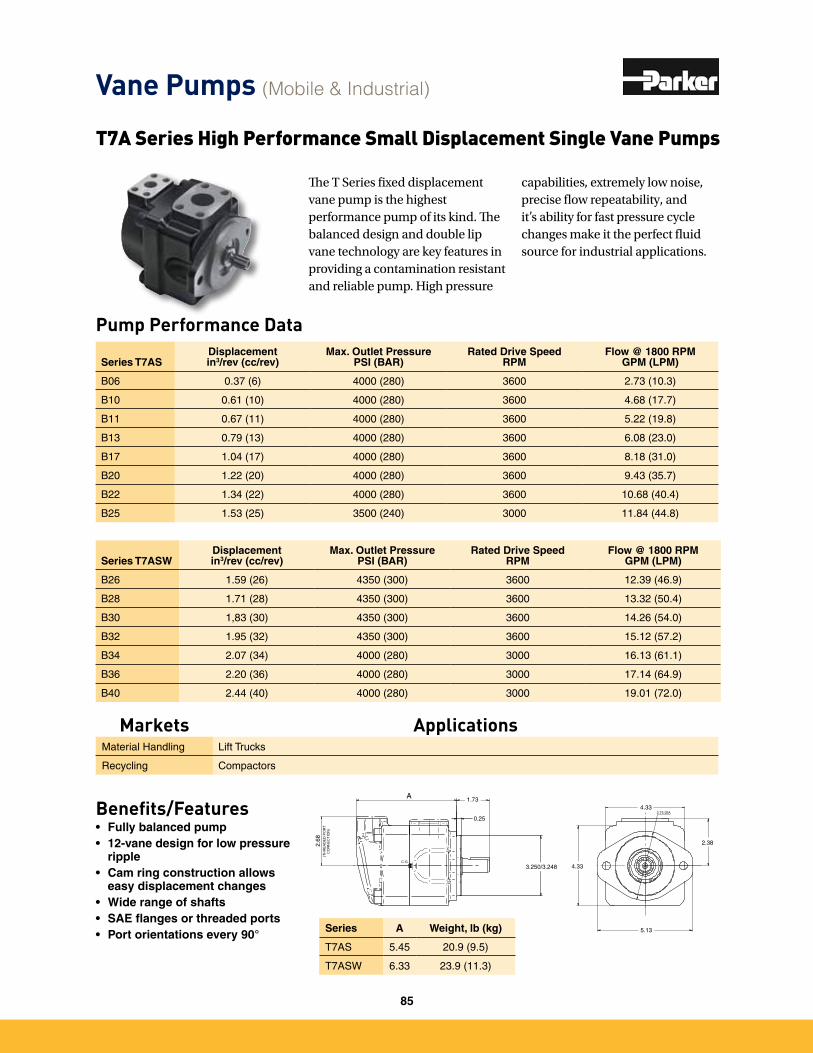
Benefits/Features• Fully balanced pump• 12-vane design for low pressure
ripple• Cam ring construction allows
easy displacement changes• Wide range of shafts• SAE flanges or threaded ports• Port orientations every 90°
T7A Series High Performance Small Displacement Single Vane Pumps
The T Series fixed displacement vane pump is the highest performance pump of its kind. The balanced design and double lip vane technology are key features in providing a contamination resistant and reliable pump. High pressure
capabilities, extremely low noise, precise flow repeatability, and it’s ability for fast pressure cycle changes make it the perfect fluid source for industrial applications.
Series T7ASDisplacementin3/rev (cc/rev)
Max. Outlet PressurePSI (BAR)
Rated Drive SpeedRPM
Flow @ 1800 RPMGPM (LPM)
B06 0�37 (6) 4000 (280) 3600 2�73 (10�3)
B10 0�61 (10) 4000 (280) 3600 4�68 (17�7)
B11 0�67 (11) 4000 (280) 3600 5�22 (19�8)
B13 0�79 (13) 4000 (280) 3600 6�08 (23�0)
B17 1�04 (17) 4000 (280) 3600 8�18 (31�0)
B20 1�22 (20) 4000 (280) 3600 9�43 (35�7)
B22 1�34 (22) 4000 (280) 3600 10�68 (40�4)
B25 1�53 (25) 3500 (240) 3000 11�84 (44�8)
Series T7ASWDisplacementin3/rev (cc/rev)
Max. Outlet PressurePSI (BAR)
Rated Drive SpeedRPM
Flow @ 1800 RPMGPM (LPM)
B26 1�59 (26) 4350 (300) 3600 12�39 (46�9)
B28 1�71 (28) 4350 (300) 3600 13�32 (50�4)
B30 1,83 (30) 4350 (300) 3600 14�26 (54�0)
B32 1�95 (32) 4350 (300) 3600 15�12 (57�2)
B34 2�07 (34) 4000 (280) 3000 16�13 (61�1)
B36 2�20 (36) 4000 (280) 3000 17�14 (64�9)
B40 2�44 (40) 4000 (280) 3000 19�01 (72�0)
Vane Pumps (Mobile & Industrial)
Markets ApplicationsMaterial Handling Lift Trucks
Recycling Compactors
3.75 DIA
(THR
EAD
ED P
ORT
CO
NNEC
TIO
N)
C.G.
2.68
A
0.25
2.38
1.734.33
5.13
3.250/3.248 4.33
Series A Weight, lb (kg)
T7AS 5�45 20�9 (9�5)
T7ASW 6�33 23�9 (11�3)
Pump Performance Data
85
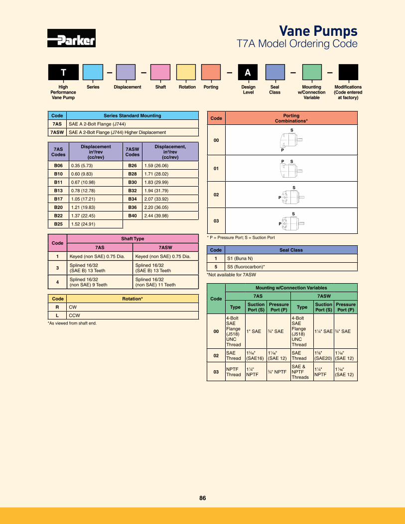
T ASeriesHigh
PerformanceVane Pump
Displacement Mountingw/Connection
Variable
Rotation Design Level
Seal Class
Shaft
– – –Modifications(Code entered
at factory)
– –Porting
Code Series Standard Mounting
7AS SAE A 2-Bolt Flange (J744)
7ASW SAE A 2-Bolt Flange (J744) Higher Displacement
7ASCodes
Displacement in3/rev
(cc/rev)
7ASW Codes
Displacement, in3/rev
(cc/rev)
B06 0�35 (5�73) B26 1�59 (26�06)
B10 0�60 (9�83) B28 1�71 (28�02)
B11 0�67 (10�98) B30 1�83 (29�99)
B13 0�78 (12�78) B32 1�94 (31�79)
B17 1�05 (17�21) B34 2�07 (33�92)
B20 1�21 (19�83) B36 2�20 (36�05)
B22 1�37 (22�45) B40 2�44 (39�98)
B25 1�52 (24�91)
CodeShaft Type
7AS 7ASW
1 Keyed (non SAE) 0�75 Dia� Keyed (non SAE) 0�75 Dia�
3 Splined 16/32 (SAE B) 13 Teeth
Splined 16/32 (SAE B) 13 Teeth
4 Splined 16/32 (non SAE) 9 Teeth
Splined 16/32 (non SAE) 11 Teeth
Code Rotation*
R CW
L CCW
Code Seal Class
1 S1 (Buna N)
5 S5 (fluorocarbon)*
Code Porting Combinations*
00
S
P
01
SP
02
S
P
03
S
P
* P = Pressure Port; S = Suction Port
Code
Mounting w/Connection Variables
7AS 7ASW
Type Suction Port (S)
Pressure Port (P) Type Suction
Port (S)Pressure Port (P)
00
4-Bolt SAE Flange (J518)UNC Thread
1" SAE 3⁄v" SAE
4-Bolt SAE Flange (J518)UNC Thread
11⁄v" SAE 3⁄v" SAE
02 SAE Thread
15⁄zn" (SAE16)
11⁄zn"(SAE 12)
SAE Thread
15⁄," (SAE20)
11⁄zn"(SAE 12)
03 NPTF Thread
11⁄v" NPTF
3⁄v" NPTFSAE & NPTF Threads
11⁄v" NPTF
11⁄zn"(SAE 12)
*Not available for 7ASW
*As viewed from shaft end�
Vane Pumps T7A Model Ordering Code
86
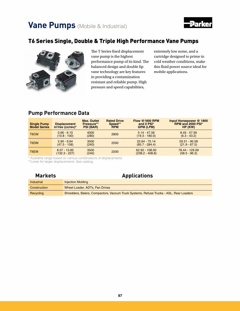
T6 Series Single, Double & Triple High Performance Vane Pumps
* Available range based on various combinations of displacements **Lower for larger displacements. See catalog.
Pump Performance Data
Single Pump Model Series
Displacement in3/rev (cc/rev)*
Max. Outlet Pressure**PSI (BAR)
Rated Drive Speed**
RPM
Flow @1800 RPM and 0 PSI*GPM (LPM)
Input Horsepower @ 1800 RPM and 2000 PSI*
HP (KW)
T6CM 0�66 - 6�10(10�8 - 100)
4000(280) 2800 5�14 - 47�56
(19�3 - 180�0)8�45 - 57�95(6�3 - 43�2)
T6DM 2�90 - 9�64(47�5 - 158)
3500(240) 2500 22�64 - 75�14
(85�7 - 284�4)29�31 - 90�58(21�9 - 67�5)
T6EM 8�07 - 13�85(132�3 - 227)
3500(240) 2200 62�92 - 108�00
(238�2 - 408�8)78�44 - 129�09(58�5 - 96�3)
The T Series fixed displacement vane pump is the highest performance pump of its kind. The balanced design and double lip vane technology are key features in providing a contamination resistant and reliable pump. High pressure and speed capabilities,
extremely low noise, and a cartridge designed to prime in cold weather conditions, make this fluid power source ideal for mobile applications.
Vane Pumps (Mobile & Industrial)
Markets ApplicationsIndustrial Injection Molding
Construction Wheel Loader, ADTs, Fan Drives
Recycling Shredders, Balers, Compactors, Vaccum Truck Systems, Refuse Trucks - ASL, Rear Loaders
87
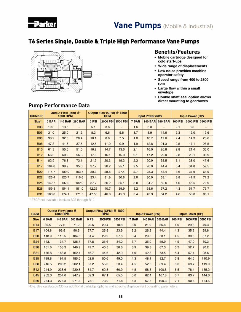
Single Pump Model Series
Displacement in3/rev (cc/rev)*
Max. Outlet Pressure**PSI (BAR)
Rated Drive Speed**
RPM
Flow @1800 RPM and 0 PSI*GPM (LPM)
Input Horsepower @ 1800 RPM and 2000 PSI*
HP (KW)
T6CM 0�66 - 6�10(10�8 - 100)
4000(280) 2800 5�14 - 47�56
(19�3 - 180�0)8�45 - 57�95(6�3 - 43�2)
T6DM 2�90 - 9�64(47�5 - 158)
3500(240) 2500 22�64 - 75�14
(85�7 - 284�4)29�31 - 90�58(21�9 - 67�5)
T6EM 8�07 - 13�85(132�3 - 227)
3500(240) 2200 62�92 - 108�00
(238�2 - 408�8)78�44 - 129�09(58�5 - 96�3)
T6DMOutput Flow (lpm) @
1800 RPMOutput Flow (GPM) @ 1800
RPM Input Power (kW) Input Power (HP)
Size 0 BAR 140 BAR 300 BAR 0 PSI 2000 PSI 3500 PSI 7 BAR 140 BAR 300 BAR 100 PSI 2000 PSI 3500 PSI
B14 85�5 77�2 71�2 22�6 20�4 18�8 3�0 21�9 36�8 4�0 29�3 49�3
B17 104�8 96�5 90�5 27�7 25�5 23�9 3�2 26�2 44�4 4�3 35�2 59�6
B20 118�9 110�5 104�5 31�4 29�2 27�6 3�4 29�5 50�1 4�5 39�5 67�2
B24 143�1 134�7 128�7 37�8 35�6 34�0 3�7 35�0 59�9 4�9 47�0 80�3
B28 161�6 153�3 146�9 42�7 40�5 38�8 3�9 39�3 67�3 5�2 52�7 90�2
B31 176�8 168�8 162�4 46�7 44�6 42�9 4�0 42�8 73�5 5�4 57�4 98�6
B35 199�8 191�5 185�5 52�8 50�6 49�0 4�3 48�1 82�7 5�8 64�5 110�9
B38 216�5 208�2 202�1 57�2 55�0 53�4 4�5 52�0 89�4 6�0 69�7 119�9
B42 244�9 236�6 230�5 64�7 62�5 60�9 4�8 58�5 100�8 6�5 78�4 135�2
B45 262�3 254�0 247�9 69�3 67�1 65�5 5�0 62�4 107�8 6�7 83�7 144�6
B50 284�3 276�3 271�8 75�1 73�0 71�8 5�3 67�6 100�3 7�1 90�6 134�5
Note: See catalog on CD for additional cartridge options and specific displacement operating parameters.
Benefits/Features• Mobile cartridge designed for
cold start-ups• Wide range of displacements• Low noise provides machine
operator safety• Speed range from 400 to 2800
rpm• Large flow within a small
envelope• Double shaft seal option allows
direct mounting to gearboxesPump Performance Data
T6CM/CPOutput Flow (lpm) @
1800 RPMOutput Flow (GPM) @ 1800
RPM Input Power (kW) Input Power (HP)
Size** 0 BAR 140 BAR 280 BAR 0 PSI 2000 PSI 3500 PSI 7 BAR 140 BAR 280 BAR 100 PSI 2000 PSI 3500 PSI
B03 19�3 13�6 – 5�1 3�6 – 1�6 6�3 – 2�1 8�5 –
B05 31�0 25�0 21�2 8�2 6�6 5�6 1�7 8�9 14�6 2�3 12�0 19�6
B06 38�2 32�6 28�4 10�1 8�6 7�5 1�8 10�7 17�6 2�4 14�3 23�6
B08 47�3 41�6 37�5 12�5 11�0 9�9 1�9 12�8 21�3 2�5 17�1 28�5
B10 61�3 55�6 51�5 16�2 14�7 13�6 2�1 16�0 26�8 2�8 21�4 36�0
B12 66�6 60�9 56�8 17�6 16�1 15�0 2�1 17�2 29�0 2�8 23�1 38�9
B14 82�9 76�8 73�1 21�9 20�3 19�3 2�3 20�9 35�5 3�1 28�0 47�6
B17 104�8 99�2 95�0 27�7 26�2 25�1 2�5 26�0 44�4 3�4 34�8 59�5
B20 114�7 109�0 103�7 30�3 28�8 27�4 2�7 28�3 48�4 3�6 37�9 64�9
B22 126�4 120�7 116�6 33�4 31�9 30�8 2�8 30�9 53�1 3�8 41�5 71�2
B25 142�7 137�0 132�9 37�7 36�2 35�1 3�0 34�7 59�6 4�0 46�5 79�9
B28 159�8 154�1 151�0 42�23 40�7 39�9 3�2 38�6 57�2 4�3 51�7 76�7
B31 180�0 174�1 171�5 47�56 46�0 45�3 3�4 43�3 64�2 4�6 58�0 86�1
** T6CP not available in sizes B03 through B12
T6 Series Single, Double & Triple High Performance Vane Pumps
Vane Pumps (Mobile & Industrial)
88
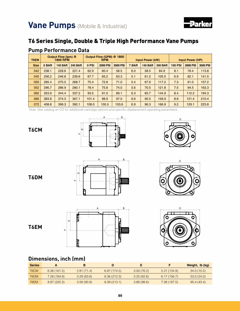
Pump Performance Data
T6EMOutput Flow (lpm) @
1800 RPMOutput Flow (GPM) @ 1800
RPM Input Power (kW) Input Power (HP)
Size 0 BAR 140 BAR 240 BAR 0 PSI 2000 PSI 3500 PSI 7 BAR 140 BAR 300 BAR 100 PSI 2000 PSI 3500 PSI
042 238�1 228�6 221�4 62�9 60�4 58�5 6�0 58�5 84�9 8�1 78�4 113�8
045 256�2 246�8 239�6 67�7 65�2 63�3 5�1 61�2 105�5 6�9 82�1 141�5
050 285�4 275�5 268�7 75�4 72�8 71�0 5�4 67�9 117�2 7�3 91�0 157�2
052 296�7 286�9 280�1 78�4 75�8 74�0 5�6 70�5 121�8 7�5 94�5 163�3
062 353�9 344�4 337�2 93�5 91�0 89�1 6�3 83�7 144�9 8�4 112�2 194�3
066 383�8 374�3 367�1 101�4 98�9 97�0 6�6 90�5 156�9 8�8 121�4 210�4
072 408�8 399�3 392�1 108�0 105�5 103�6 6�9 96�3 166�9 9�2 129�1 223�8
Note: See catalog on CD for additional cartridge options and specific displacement operating parameters.
Dimensions, inch (mm)Series A B D E F Weight, lb (kg)
T6CM 6.36 (161.5) 2.81 (71.4) 6.87 (174.5) 3.00 (76.2) 5.31 (134.9) 34.0 (15.5)
T6DM 7.28 (184.9) 3.29 (83.6) 8.36 (212.3) 3.25 (82.6) 6.17 (156.7) 53.0 (24.0)
T6EM 8.87 (225.3) 3.58 (90.9) 8.39 (213.1) 3.88 (98.6) 7.38 (187.5) 95.4 (43.4)
T6CM
T6DM
T6EM
F
E
A DB
DA B
FE
EF
A BD
Vane Pumps (Mobile & Industrial)
T6 Series Single, Double & Triple High Performance Vane Pumps
89
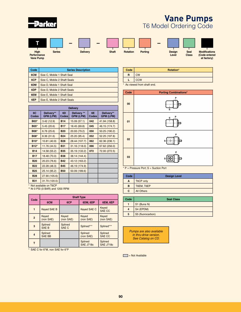
Series A B D E F Weight, lb (kg)
T6CM 6.36 (161.5) 2.81 (71.4) 6.87 (174.5) 3.00 (76.2) 5.31 (134.9) 34.0 (15.5)
T6DM 7.28 (184.9) 3.29 (83.6) 8.36 (212.3) 3.25 (82.6) 6.17 (156.7) 53.0 (24.0)
T6EM 8.87 (225.3) 3.58 (90.9) 8.39 (213.1) 3.88 (98.6) 7.38 (187.5) 95.4 (43.4)
T
Code Rotation*
R CW
L CCW
* As viewed from shaft end�
Code Series Description
6CM Size C, Mobile 1 Shaft Seal
6CP Size C, Mobile 2 Shaft Seals
6DM Size D, Mobile 1 Shaft Seal
6DP Size D, Mobile 2 Shaft Seals
6EM Size E, Mobile 1 Shaft Seal
6EP Size E, Mobile 2 Shaft Seals
Code Seal Class
1 S1 (Buna N)
4 S4 (EPDM)
5 S5 (fluorocarbon)
SeriesHigh PerformanceVane Pump
Delivery Rotation Porting Design Level
Seal Class
Shaft
– –
CodeShaft Type
6CM 6CP 6DM, 6DP 6EM, 6EP
1 Keyed SAE B Keyed SAE C Keyed SAE CC
2 Keyed (non SAE)
Keyed (non SAE)
Keyed (non SAE)
Keyed (non SAE)
3 Splined SAE B
Splined SAE C Splined*** Splined***
4 Splined SAE BB
Splined (non SAE)
Splined SAE CC
T SplinedSAE J718c
SplinedSAE J718c
* SAE C for 6*M, non SAE for 6*P
Delivery
6C Codes
Delivery**GPM (LPM)
6D Codes
Delivery **GPM (LPM)
6E Codes
Delivery**GPM (LPM)
B03* 3�42 (12�9) B14 15�09 (57�1) 042 41�94 (158�8)
B05* 5�45 (20�6) B17 18�45 (69�8) 045 46�15 (174�7)
B06* 6�76 (25�6) B20 20�93 (79�2) 050 50�25 (190�2)
B08* 8�36 (31�6) B24 25�20 (95�4) 052 52�25 (197�8)
B10* 10�81 (40�9) B28 28�44 (107�7) 062 62�36 (236�1)
B12* 11�76 (44�5) B31 31�16 (118�0) 066 67�62 (256�0)
B14 14�58 (55�2) B35 35�19 (133�2) 072 72�00 (272�5)
B17 18�48 (70�0) B38 38�14 (144�4)
B20 20�23 (76�6) B42 43�12 (163�2)
B22 22�28 (48�3) B45 46�19 (174�9)
B25 25�14 (95�2) B50 50�09 (189�6)
B28 27�90 (105�6)
B31 31�70 (120�0)
* Not available on T6CP** At 0 PSI (0 BAR) and 1200 RPM
Code Porting Combinations*
00
P
S
01
PS
02
P
S
03
P
S
* P = Pressure Port; S = Suction Port
–Modifications(Code entered
at factory)
Code Design Level
A T6CP only
B T6EM, T6EP
C All Others
Pumps are also available in thru-drive version. See Catalog on CD.
= Not Available
Vane Pumps T6 Model Ordering Code
90
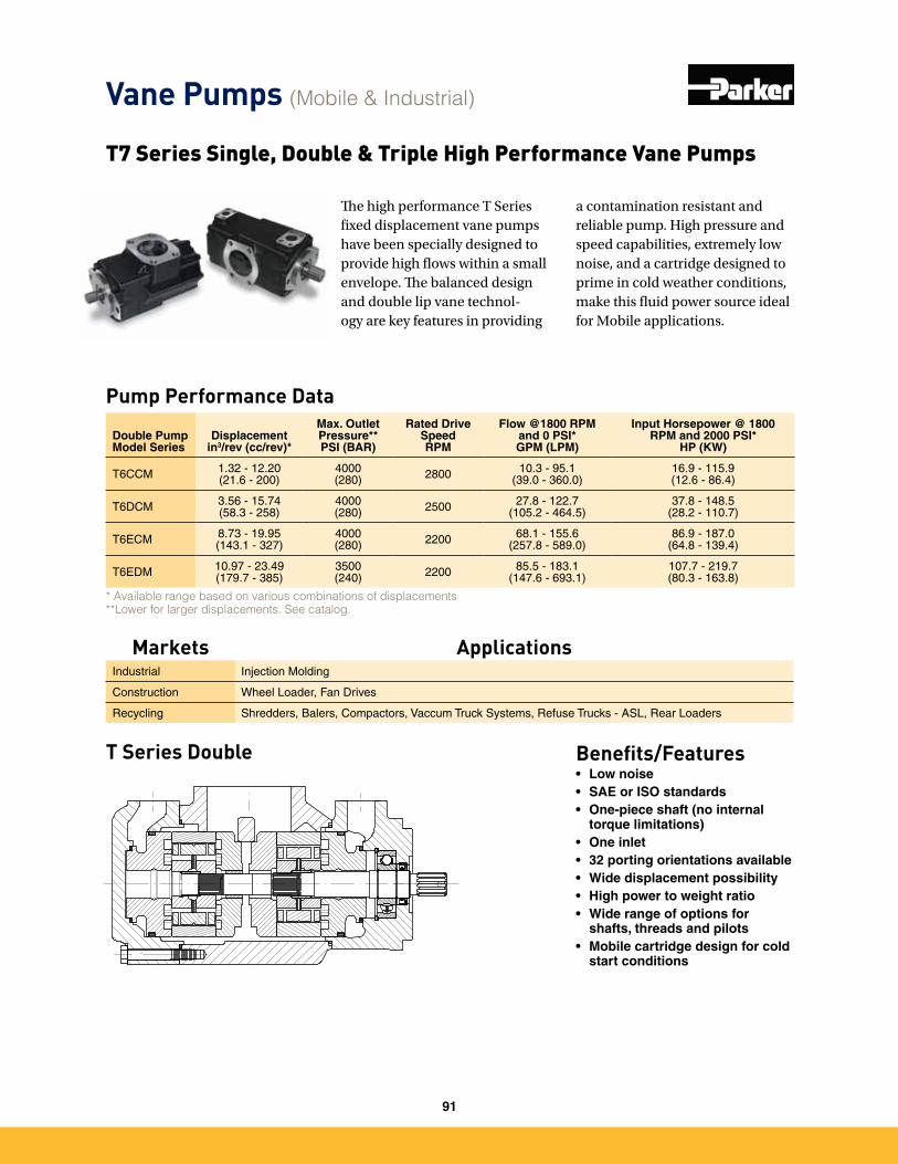
T7 Series Single, Double & Triple High Performance Vane Pumps
* Available range based on various combinations of displacements **Lower for larger displacements. See catalog.
Pump Performance Data
Double Pump Model Series
Displacement in3/rev (cc/rev)*
Max. Outlet Pressure**PSI (BAR)
Rated Drive SpeedRPM
Flow @1800 RPM and 0 PSI*GPM (LPM)
Input Horsepower @ 1800 RPM and 2000 PSI*
HP (KW)
T6CCM 1�32 - 12�20(21�6 - 200)
4000(280) 2800 10�3 - 95�1
(39�0 - 360�0)16�9 - 115�9(12�6 - 86�4)
T6DCM 3�56 - 15�74(58�3 - 258)
4000(280) 2500 27�8 - 122�7
(105�2 - 464�5)37�8 - 148�5
(28�2 - 110�7)
T6ECM 8�73 - 19�95(143�1 - 327)
4000(280) 2200 68�1 - 155�6
(257�8 - 589�0)86�9 - 187�0
(64�8 - 139�4)
T6EDM 10�97 - 23�49(179�7 - 385)
3500(240) 2200 85�5 - 183�1
(147�6 - 693�1)107�7 - 219�7(80�3 - 163�8)
T Series Double Benefits/Features• Low noise• SAE or ISO standards• One-piece shaft (no internal
torque limitations)• One inlet• 32 porting orientations available• Wide displacement possibility• High power to weight ratio• Wide range of options for
shafts, threads and pilots• Mobile cartridge design for cold
start conditions
The high performance T Series fixed displacement vane pumps have been specially designed to provide high flows within a small envelope. The balanced design and double lip vane technol-ogy are key features in providing
a contamination resistant and reliable pump. High pressure and speed capabilities, extremely low noise, and a cartridge designed to prime in cold weather conditions, make this fluid power source ideal for Mobile applications.
Vane Pumps (Mobile & Industrial)
Markets ApplicationsIndustrial Injection Molding
Construction Wheel Loader, Fan Drives
Recycling Shredders, Balers, Compactors, Vaccum Truck Systems, Refuse Trucks - ASL, Rear Loaders
91
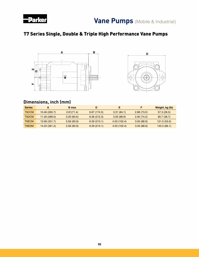
Dimensions, inch (mm)Series A B max D E F Weight, kg (lb)
T6CCM 10�46 (265�7) 2�81(71�4) 6�87 (174�5) 3�31 (84�1) 2�88 (73�2) 57�3 (26�0)
T6DCM 11�26 (286�0) 3�29 (83�6) 8�36 (212�3) 3�50 (88�9) 2�92 (74�2) 80�7 (36�7)
T6ECM 13�06 (331�7) 3�58 (90�9) 8�39 (213�1) 4�03 (102�4) 3�50 (88�9) 121�0 (55�0)
T6EDM 14�22 (361�2) 3�58 (90�9) 8�39 (213�1) 4�03 (102�4) 3�50 (88�9) 145�5 (66�1)
C.G.
A B D
FE
GT7 Series Single, Double & Triple High Performance Vane Pumps
Vane Pumps (Mobile & Industrial)
92
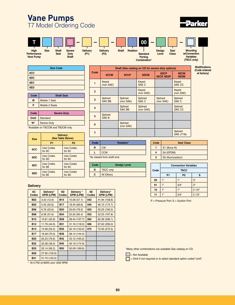
Vane Pumps T7 Model Ordering Code
T
Code Rotation*
R CW
L CCW
*As viewed from shaft end�
Code Seal Class
1 S1 (Buna N)
4 S4 (EPDM)
5 S5 (fluorocarbon)
High PerformanceVane Pump
Delivery(P1)
RotationStandardPorting
Combination1
Design Level
Seal Class
Shaft
Code
Shaft (See catalog on CD for severe duty options)
6CCM 6CCP 6DCM 6DCP6ECP, 6EDP
6ECM6EDM
1 Keyed (non SAE)
KeyedSAE C
KeyedSAE CC
2 Keyed(non SAE)
Keyed(non SAE)
3 SplinedSAE BB
Splined (non SAE)
SplinedSAE C
Splined(non SAE)
SplinedSAE C
4 SplinedSAE BB
Splined(non SAE)
SplinedSAE CC
5 SplinedSAE B
6 Splined(non SAE)
T Splined SAE J718c
Modifications(Code entered
at factory)
–Delivery
(P2)
– – – –
Delivery
Size Code
6CC
6DC
6EC
6ED
SizeDelivery
(See Table Below)
P1 P2
6CC Use Codes for 6C
Use Codes for 6C
6DC Use Codes for 6D
Use Codes for 6C
6EC Use Codes for 6E
Use Codes for 6C
6ED Use Codes for 6E
Use Codes for 6D
Code
Connection Variables
T6CC
P1 P2 S
00 1" 1" 3"
01 1" 3/4" 3"
10 1" 1" 2 1/2"
11 1" 3/4" 2 1/2"
P = Pressure Port; S = Suction Port
00Size Shaft
SealSevereDutyShaft
Code Shaft Seal
M Mobile 1 Seal
P Mobile 2 Seals
Code Severe Duty
Omit Standard
W* Severe Duty
*Available on T6CCM and T6DCM only�
6C Codes
Delivery*GPM (LPM)
6D Codes
Delivery *GPM (LPM)
6E Codes
Delivery*GPM (LPM)
B03 3�42 (12�9) B14 15�09 (57�1) 042 41�94 (158�8)
B05 5�45 (20�6) B17 18�45 (69�8) 045 46�15 (174�7)
B06 6�76 (25�6) B20 20�93 (79�2) 050 50�25 (190�2)
B08 8�36 (31�6) B24 25�20 (95�4) 052 52�25 (197�8)
B10 10�81 (40�9) B28 28�44 (107�7) 062 62�36 (236�1)
B12 11�76 (44�5) B31 31�16 (118�0) 066 67�62 (256�0)
B14 14�58 (55�2) B35 35�19 (133�2) 072 72�00 (272�5)
B17 18�48 (70�0) B38 38�14 (144�4)
B20 20�23 (76�6) B42 43�12 (163�2)
B22 22�28 (48�3) B45 46�19 (174�9)
B25 25�14 (95�2) B50 50�09 (189�6)
B28 27�90 (105�6)
B31 31�70 (120�0)
* At 0 PSI (0 BAR) and 1200 RPM
Code Deslgn Level
D T6CC only
C All Others
= Not Available
1Many other combinations are available See catalog on CD�
= Omit if not required or to select standard option coded “omit”�
Mounting w/Connection
Variables(T6CC only)
93
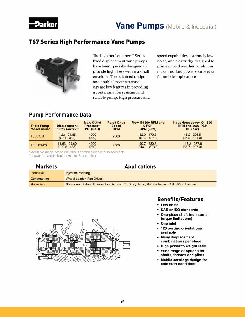
T67 Series High Performance Vane Pumps
Pump Performance Data
* Available range based on various combinations of displacements. ** Lower for larger displacements. See catalog.
Triple Pump Model Series
Displacement in3/rev (cc/rev)*
Max. Outlet Pressure**PSI (BAR)
Rated Drive SpeedRPM
Flow @1800 RPM and 0 PSI*
GPM (LPM)
Input Horsepower @ 1800 RPM and 2000 PSI*
HP (KW)
T6DCCM 4�22 - 21�85(69�1 - 358)
4000(280) 2500 32�9 - 170�3
(124�5 - 644�7)46�2 - 206�5
(34�5 - 154�0)
T6EDCM/S 11�63 - 29�60(190�5 - 485)
4000(280) 2200 90�7 - 230�7
(343�3 - 873�3)116�2 - 277�6(86�7 - 207�0)
Benefits/Features• Low noise• SAE or ISO standards• One-piece shaft (no internal
torque limitations)• One inlet• 128 porting orientations
available• Many displacement
combinations per stage• High power to weight ratio• Wide range of options for
shafts, threads and pilots• Mobile cartridge design for
cold start conditions
The high performance T Series fixed displacement vane pumps have been specially designed to provide high flows within a small envelope. The balanced design and double lip vane technol-ogy are key features in providing a contamination resistant and reliable pump. High pressure and
speed capabilities, extremely low noise, and a cartridge designed to prime in cold weather conditions, make this fluid power source ideal for mobile applications.
Vane Pumps (Mobile & Industrial)
Markets ApplicationsIndustrial Injection Molding
Construction Wheel Loader, Fan Drives
Recycling Shredders, Balers, Compactors, Vaccum Truck Systems, Refuse Trucks - ASL, Rear Loaders
94
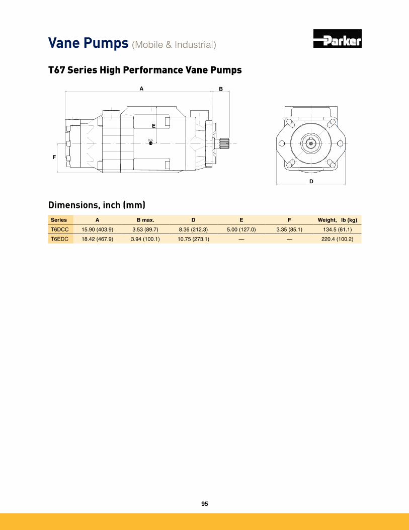
T67 Series High Performance Vane Pumps
Dimensions, inch (mm)Series A B max. D E F Weight, lb (kg)
T6DCC 15�90 (403�9) 3�53 (89�7) 8�36 (212�3) 5�00 (127�0) 3�35 (85�1) 134�5 (61�1)
T6EDC 18�42 (467�9) 3�94 (100�1) 10�75 (273�1) — — 220�4 (100�2)
C.G.
D
A B
E
F
Vane Pumps (Mobile & Industrial)
95
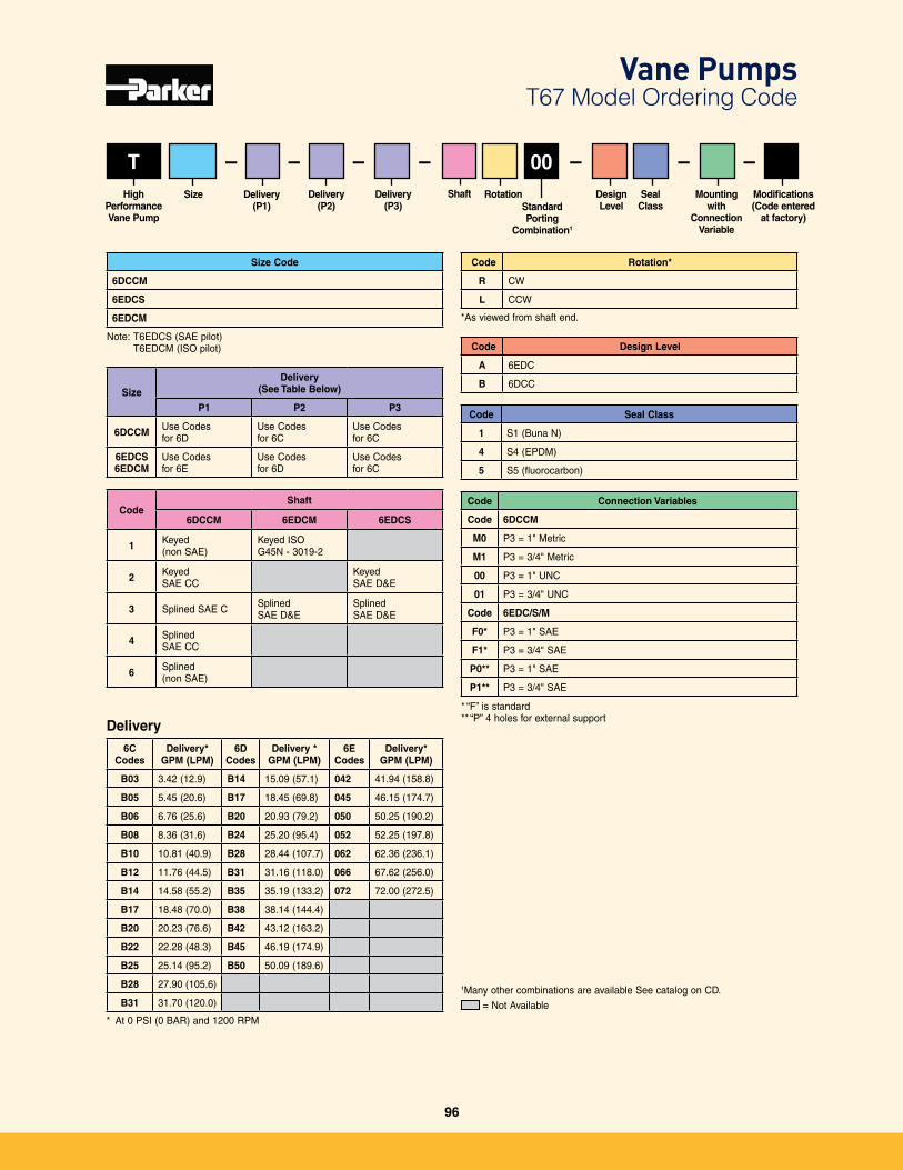
T
Code Rotation*
R CW
L CCW
*As viewed from shaft end�
Code Seal Class
1 S1 (Buna N)
4 S4 (EPDM)
5 S5 (fluorocarbon)
SizeHigh PerformanceVane Pump
Delivery(P1)
Mountingwith
Connection Variable
Rotation Design Level
Seal Class
Shaft
CodeShaft
6DCCM 6EDCM 6EDCS
1 Keyed (non SAE)
Keyed ISOG45N - 3019-2
2 Keyed SAE CC
Keyed SAE D&E
3 Splined SAE C Splined SAE D&E
Splined SAE D&E
4 Splined SAE CC
6 Splined (non SAE)
Modifications(Code entered
at factory)
–Delivery
(P2)
– – – –
Delivery
Size Code
6DCCM
6EDCS
6EDCM
SizeDelivery
(See Table Below)
P1 P2 P3
6DCCM Use Codes for 6D
Use Codes for 6C
Use Codes for 6C
6EDCS6EDCM
Use Codes for 6E
Use Codes for 6D
Use Codes for 6C
–00–Delivery
(P3)
Code Design Level
A 6EDC
B 6DCC
Code Connection Variables
Code 6DCCM
M0 P3 = 1" Metric
M1 P3 = 3/4" Metric
00 P3 = 1" UNC
01 P3 = 3/4" UNC
Code 6EDC/S/M
F0* P3 = 1" SAE
F1* P3 = 3/4" SAE
P0** P3 = 1" SAE
P1** P3 = 3/4" SAE
= Not Available
1Many other combinations are available See catalog on CD�
Note: T6EDCS (SAE pilot) T6EDCM (ISO pilot)
* “F” is standard** “P” 4 holes for external support
Vane Pumps T67 Model Ordering Code
StandardPorting
Combination1
6C Codes
Delivery*GPM (LPM)
6D Codes
Delivery *GPM (LPM)
6E Codes
Delivery*GPM (LPM)
B03 3�42 (12�9) B14 15�09 (57�1) 042 41�94 (158�8)
B05 5�45 (20�6) B17 18�45 (69�8) 045 46�15 (174�7)
B06 6�76 (25�6) B20 20�93 (79�2) 050 50�25 (190�2)
B08 8�36 (31�6) B24 25�20 (95�4) 052 52�25 (197�8)
B10 10�81 (40�9) B28 28�44 (107�7) 062 62�36 (236�1)
B12 11�76 (44�5) B31 31�16 (118�0) 066 67�62 (256�0)
B14 14�58 (55�2) B35 35�19 (133�2) 072 72�00 (272�5)
B17 18�48 (70�0) B38 38�14 (144�4)
B20 20�23 (76�6) B42 43�12 (163�2)
B22 22�28 (48�3) B45 46�19 (174�9)
B25 25�14 (95�2) B50 50�09 (189�6)
B28 27�90 (105�6)
B31 31�70 (120�0)
* At 0 PSI (0 BAR) and 1200 RPM
96
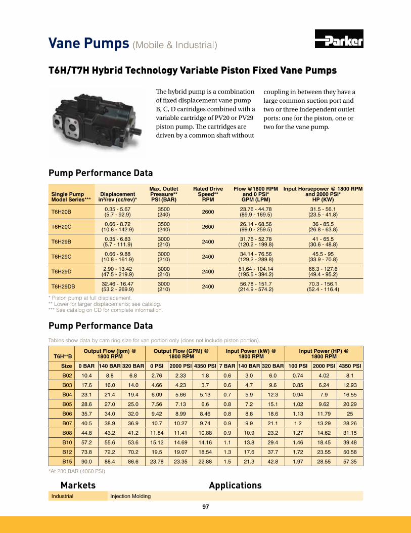
Pump Performance Data
T6H/T7H Hybrid Technology Variable Piston Fixed Vane Pumps
The hybrid pump is a combination of fixed displacement vane pump B, C, D cartridges combined with a variable cartridge of PV20 or PV29 piston pump. The cartridges are driven by a common shaft without
Pump Performance Data
T6H**BOutput Flow (lpm) @
1800 RPMOutput Flow (GPM) @
1800 RPMInput Power (kW) @
1800 RPMInput Power (HP) @
1800 RPM
Size 0 BAR 140 BAR 320 BAR 0 PSI 2000 PSI 4350 PSI 7 BAR 140 BAR 320 BAR 100 PSI 2000 PSI 4350 PSI
B02 10�4 8�8 6�8 2�76 2�33 1�8 0�6 3�0 6�0 0�74 4�02 8�1
B03 17�6 16�0 14�0 4�66 4�23 3�7 0�6 4�7 9�6 0�85 6�24 12�93
B04 23�1 21�4 19�4 6�09 5�66 5�13 0�7 5�9 12�3 0�94 7�9 16�55
B05 28�6 27�0 25�0 7�56 7�13 6�6 0�8 7�2 15�1 1�02 9�62 20�29
B06 35�7 34�0 32�0 9�42 8�99 8�46 0�8 8�8 18�6 1�13 11�79 25
B07 40�5 38�9 36�9 10�7 10�27 9�74 0�9 9�9 21�1 1�2 13�29 28�26
B08 44�8 43�2 41�2 11�84 11�41 10�88 0�9 10�9 23�2 1�27 14�62 31�15
B10 57�2 55�6 53�6 15�12 14�69 14�16 1�1 13�8 29�4 1�46 18�45 39�48
B12 73�8 72�2 70�2 19�5 19�07 18�54 1�3 17�6 37�7 1�72 23�55 50�58
B15 90�0 88�4 86�6 23�78 23�35 22�88 1�5 21�3 42�8 1�97 28�55 57�35
*At 280 BAR (4060 PSI)
Tables show data by cam ring size for van portion only (does not include piston portion).
Single Pump Model Series***
Displacement in3/rev (cc/rev)*
Max. Outlet Pressure**PSI (BAR)
Rated Drive Speed**
RPM
Flow @1800 RPM and 0 PSI*GPM (LPM)
Input Horsepower @ 1800 RPM and 2000 PSI*
HP (KW)
T6H20B 0�35 - 5�67(5�7 - 92�9)
3500(240) 2600 23�76 - 44�78
(89�9 - 169�5)31�5 - 56�1
(23�5 - 41�8)
T6H20C 0�66 - 8�72(10�8 - 142�9)
3500(240) 2600 26�14 - 68�56
(99�0 - 259�5)36 - 85�5
(26�8 - 63�8)
T6H29B 0�35 - 6�83(5�7 - 111�9)
3000(210) 2400 31�76 - 52�78
(120�2 - 199�8)41 - 65�5
(30�6 - 48�8)
T6H29C 0�66 - 9�88(10�8 - 161�9)
3000(210) 2400 34�14 - 76�56
(129�2 - 289�8)45�5 - 95
(33�9 - 70�8)
T6H29D 2�90 - 13�42(47�5 - 219�9)
3000(210) 2400 51�64 - 104�14
(195�5 - 394�2)66�3 - 127�6(49�4 - 95�2)
T6H29DB 32�46 - 16�47(53�2 - 269�9)
3000(210) 2400 56�78 - 151�7
(214�9 - 574�2)70�3 - 156�1
(52�4 - 116�4)
* Piston pump at full displacement.** Lower for larger displacements; see catalog.*** See catalog on CD for complete information.
Vane Pumps (Mobile & Industrial)
Markets ApplicationsIndustrial Injection Molding
coupling in between they have a large common suction port and two or three independent outlet ports: one for the piston, one or two for the vane pump.
97
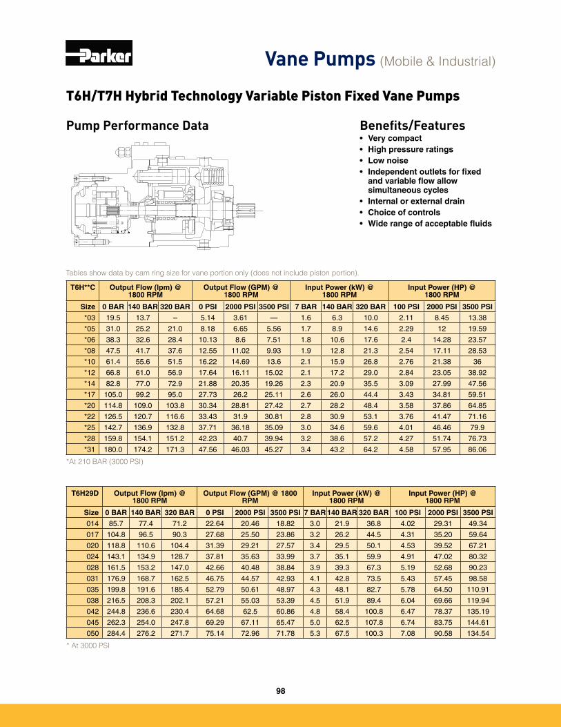
Pump Performance Data Benefits/Features• Very compact • High pressure ratings• Low noise• Independent outlets for fixed
and variable flow allow simultaneous cycles
• Internal or external drain• Choice of controls• Wide range of acceptable fluids
T6H29D Output Flow (lpm) @ 1800 RPM
Output Flow (GPM) @ 1800 RPM
Input Power (kW) @ 1800 RPM
Input Power (HP) @ 1800 RPM
Size 0 BAR 140 BAR 320 BAR 0 PSI 2000 PSI 3500 PSI 7 BAR 140 BAR 320 BAR 100 PSI 2000 PSI 3500 PSI
014 85�7 77�4 71�2 22�64 20�46 18�82 3�0 21�9 36�8 4�02 29�31 49�34
017 104�8 96�5 90�3 27�68 25�50 23�86 3�2 26�2 44�5 4�31 35�20 59�64
020 118�8 110�6 104�4 31�39 29�21 27�57 3�4 29�5 50�1 4�53 39�52 67�21
024 143�1 134�9 128�7 37�81 35�63 33�99 3�7 35�1 59�9 4�91 47�02 80�32
028 161�5 153�2 147�0 42�66 40�48 38�84 3�9 39�3 67�3 5�19 52�68 90�23
031 176�9 168�7 162�5 46�75 44�57 42�93 4�1 42�8 73�5 5�43 57�45 98�58
035 199�8 191�6 185�4 52�79 50�61 48�97 4�3 48�1 82�7 5�78 64�50 110�91
038 216�5 208�3 202�1 57�21 55�03 53�39 4�5 51�9 89�4 6�04 69�66 119�94
042 244�8 236�6 230�4 64�68 62�5 60�86 4�8 58�4 100�8 6�47 78�37 135�19
045 262�3 254�0 247�8 69�29 67�11 65�47 5�0 62�5 107�8 6�74 83�75 144�61
050 284�4 276�2 271�7 75�14 72�96 71�78 5�3 67�5 100�3 7�08 90�58 134�54
* At 3000 PSI
T6H**C Output Flow (lpm) @ 1800 RPM
Output Flow (GPM) @ 1800 RPM
Input Power (kW) @ 1800 RPM
Input Power (HP) @ 1800 RPM
Size 0 BAR 140 BAR 320 BAR 0 PSI 2000 PSI 3500 PSI 7 BAR 140 BAR 320 BAR 100 PSI 2000 PSI 3500 PSI
*03 19�5 13�7 – 5�14 3�61 — 1�6 6�3 10�0 2�11 8�45 13�38
*05 31�0 25�2 21�0 8�18 6�65 5�56 1�7 8�9 14�6 2�29 12 19�59
*06 38�3 32�6 28�4 10�13 8�6 7�51 1�8 10�6 17�6 2�4 14�28 23�57
*08 47�5 41�7 37�6 12�55 11�02 9�93 1�9 12�8 21�3 2�54 17�11 28�53
*10 61�4 55�6 51�5 16�22 14�69 13�6 2�1 15�9 26�8 2�76 21�38 36
*12 66�8 61�0 56�9 17�64 16�11 15�02 2�1 17�2 29�0 2�84 23�05 38�92
*14 82�8 77�0 72�9 21�88 20�35 19�26 2�3 20�9 35�5 3�09 27�99 47�56
*17 105�0 99�2 95�0 27�73 26�2 25�11 2�6 26�0 44�4 3�43 34�81 59�51
*20 114�8 109�0 103�8 30�34 28�81 27�42 2�7 28�2 48�4 3�58 37�86 64�85
*22 126�5 120�7 116�6 33�43 31�9 30�81 2�8 30�9 53�1 3�76 41�47 71�16
*25 142�7 136�9 132�8 37�71 36�18 35�09 3�0 34�6 59�6 4�01 46�46 79�9
*28 159�8 154�1 151�2 42�23 40�7 39�94 3�2 38�6 57�2 4�27 51�74 76�73
*31 180�0 174�2 171�3 47�56 46�03 45�27 3�4 43�2 64�2 4�58 57�95 86�06
*At 210 BAR (3000 PSI)
Tables show data by cam ring size for vane portion only (does not include piston portion).
T6H/T7H Hybrid Technology Variable Piston Fixed Vane Pumps
Vane Pumps (Mobile & Industrial)
98
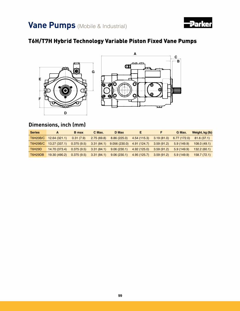
Dimensions, inch (mm)
D
G
F
E
CB
A
Series A B max C Max. D Max E F G Max. Weight, kg (lb)
T6H20B/C 12�64 (321�1) 0�31 (7�9) 2�75 (69�8) 8�86 (225�0) 4�54 (115�3) 3�19 (81�0) 6�77 (172�0) 81�6 (37�1)
T6H29B/C 13�27 (337�1) 0�375 (9�5) 3�31 (84�1) 9�056 (230�0) 4�91 (124�7) 3�59 (91�2) 5�9 (149�9) 108�0 (49�1)
T6H29D 14�70 (373�4) 0�375 (9�5) 3�31 (84�1) 9�06 (230�1) 4�92 (125�0) 3�59 (91�2) 5�9 (149�9) 132�2 (60�1)
T6H29DB 19�30 (490�2) 0�375 (9�5) 3�31 (84�1) 9�06 (230�1) 4�95 (125�7) 3�59 (91�2) 5�9 (149�9) 158�7 (72�1)
Vane Pumps (Mobile & Industrial)
T6H/T7H Hybrid Technology Variable Piston Fixed Vane Pumps
99
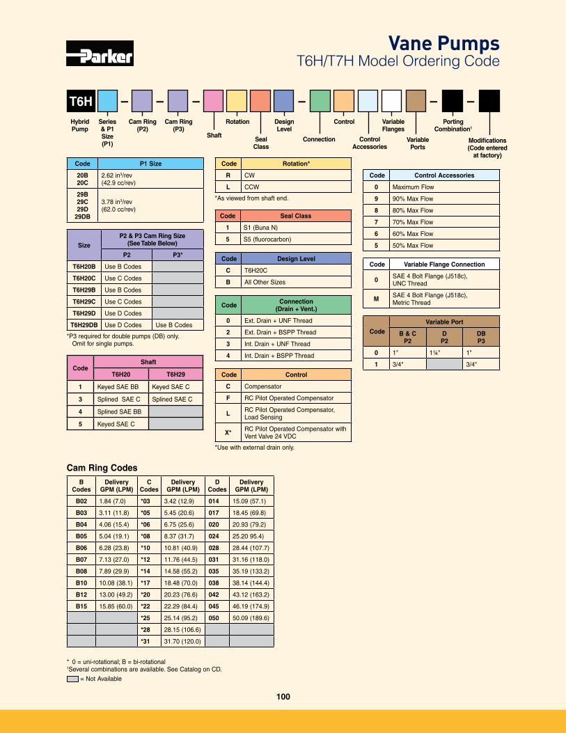
T6H
Code Rotation*
R CW
L CCW
*As viewed from shaft end�
Code Seal Class
1 S1 (Buna N)
5 S5 (fluorocarbon)
Hybrid Pump
Cam Ring(P2)
Rotation Design Level
Seal Class
Shaft
CodeShaft
T6H20 T6H29
1 Keyed SAE BB Keyed SAE C
3 Splined SAE C Splined SAE C
4 Splined SAE BB
5 Keyed SAE C
BCodes
Delivery GPM (LPM)
C Codes
Delivery GPM (LPM)
D Codes
Delivery GPM (LPM)
B02 1�84 (7�0) *03 3�42 (12�9) 014 15�09 (57�1)
B03 3�11 (11�8) *05 5�45 (20�6) 017 18�45 (69�8)
B04 4�06 (15�4) *06 6�75 (25�6) 020 20�93 (79�2)
B05 5�04 (19�1) *08 8�37 (31�7) 024 25�20 95�4)
B06 6�28 (23�8) *10 10�81 (40�9) 028 28�44 (107�7)
B07 7�13 (27�0) *12 11�76 (44�5) 031 31�16 (118�0)
B08 7�89 (29�9) *14 14�58 (55�2) 035 35�19 (133�2)
B10 10�08 (38�1) *17 18�48 (70�0) 038 38�14 (144�4)
B12 13�00 (49�2) *20 20�23 (76�6) 042 43�12 (163�2)
B15 15�85 (60�0) *22 22�29 (84�4) 045 46�19 (174�9)
*25 25�14 (95�2) 050 50�09 (189�6)
*28 28�15 (106�6)
*31 31�70 (120�0)
Modifications(Code entered
at factory)
–Cam Ring
(P3)
Cam Ring Codes
Code P1 Size
20B20C
2�62 in3/rev(42�9 cc/rev)
29B29C29D
29DB
3�78 in3/rev(62�0 cc/rev)
SizeP2 & P3 Cam Ring Size
(See Table Below)
P2 P3*
T6H20B Use B Codes
T6H20C Use C Codes
T6H29B Use B Codes
T6H29C Use C Codes
T6H29D Use D Codes
T6H29DB Use D Codes Use B Codes
*P3 required for double pumps (DB) only� Omit for single pumps�
Code Design Level
C T6H20C
B All Other Sizes
Series& P1Size (P1)
– – – ––
Connection
Control
Control Accessories
Variable Flanges
PortingCombination1
Variable Ports
Code Connection (Drain + Vent.)
0 Ext� Drain + UNF Thread
2 Ext� Drain + BSPP Thread
3 Int� Drain + UNF Thread
4 Int� Drain + BSPP Thread
Code Control
C Compensator
F RC Pilot Operated Compensator
L RC Pilot Operated Compensator, Load Sensing
X* RC Pilot Operated Compensator with Vent Valve 24 VDC
*Use with external drain only�
Code Control Accessories
0 Maximum Flow
9 90% Max Flow
8 80% Max Flow
7 70% Max Flow
6 60% Max Flow
5 50% Max Flow
Code Variable Flange Connection
0 SAE 4 Bolt Flange (J518c), UNC Thread
M SAE 4 Bolt Flange (J518c), Metric Thread
CodeVariable Port
B & CP2
DP2
DBP3
0 1" 1¼" 1"
1 3/4" 3/4"
* 0 = uni-rotational; B = bi-rotational1Several combinations are available� See Catalog on CD�
Vane Pumps T6H/T7H Model Ordering Code
= Not Available
100

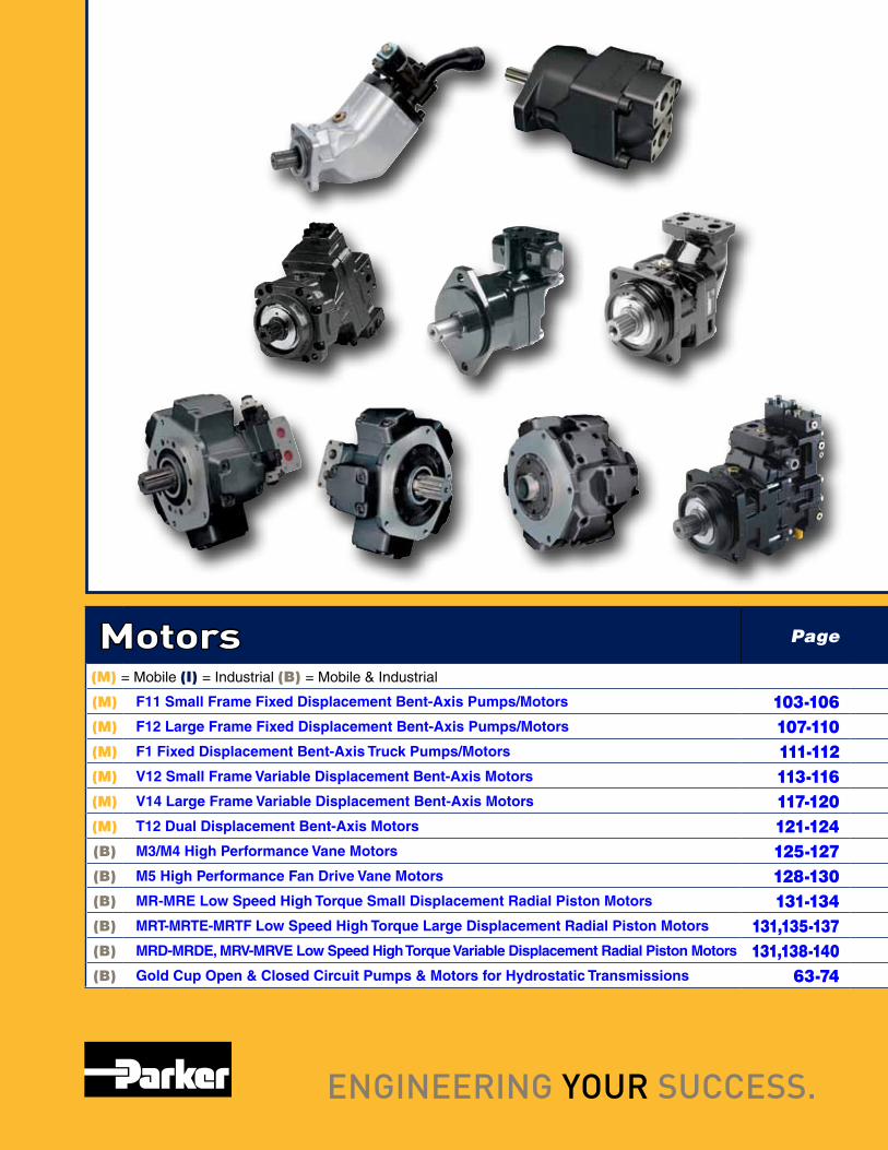
Motors Page
(M) = Mobile (I) = Industrial (B) = Mobile & Industrial
(M) F11 Small Frame Fixed Displacement Bent-Axis Pumps/Motors 103-106(M) F12 Large Frame Fixed Displacement Bent-Axis Pumps/Motors 107-110(M) F1 Fixed Displacement Bent-Axis Truck Pumps/Motors 111-112(M) V12 Small Frame Variable Displacement Bent-Axis Motors 113-116(M) V14 Large Frame Variable Displacement Bent-Axis Motors 117-120(M) T12 Dual Displacement Bent-Axis Motors 121-124(B) M3/M4 High Performance Vane Motors 125-127(B) M5 High Performance Fan Drive Vane Motors 128-130(B) MR-MRE Low Speed High Torque Small Displacement Radial Piston Motors 131-134(B) MRT-MRTE-MRTF Low Speed High Torque Large Displacement Radial Piston Motors 131,135-137(B) MRD-MRDE, MRV-MRVE Low Speed High Torque Variable Displacement Radial Piston Motors 131,138-140(B) Gold Cup Open & Closed Circuit Pumps & Motors for Hydrostatic Transmissions 63-74
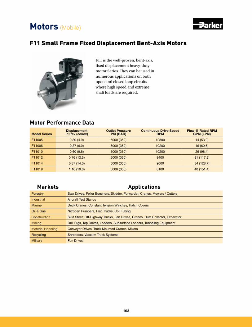
F11 is the well-proven, bent-axis, fixed displacement heavy-duty motor Series. They can be used in numerous applications on both open and closed loop circuits where high speed and extreme shaft loads are required.
Motor Performance Data
F11 Small Frame Fixed Displacement Bent-Axis Motors
Model SeriesDisplacementin3/rev (cc/rev)
Outlet PressurePSI (BAR)
Continuous Drive SpeedRPM
Flow @ Rated RPMGPM (LPM)
F11005 0�30 (4�9) 5000 (350) 12800 14 (53�0)
F11006 0�37 (6�0) 5000 (350) 10200 16 (60�6)
F11010 0�60 (9�8) 5000 (350) 10200 26 (98�4)
F11012 0�76 (12�5) 5000 (350) 9400 31 (117�3)
F11014 0�87 (14�3) 5000 (350) 9000 34 (128�7)
F11019 1�16 (19�0) 5000 (350) 8100 40 (151�4)
Motors (Mobile)
Markets ApplicationsForestry Saw Drives, Feller Bunchers, Skidder, Forwarder, Cranes, Mowers / Cutters
Industrial Aircraft Test Stands
Marine Deck Cranes, Constant Tension Winches, Hatch Covers
Oil & Gas Nitrogen Pumpers, Frac Trucks, Coil Tubing
Construction Skid Steer, Off-Highway Trucks, Fan Drives, Cranes, Dust Collector, Excavator
Mining Drill Rigs, Top Drives, Loaders, Subsurface Loaders, Tunneling Equipment
Material Handling Conveyor Drives, Truck Mounted Cranes, Mixers
Recycling Shredders, Vaccum Truck Systems
Military Fan Drives
103
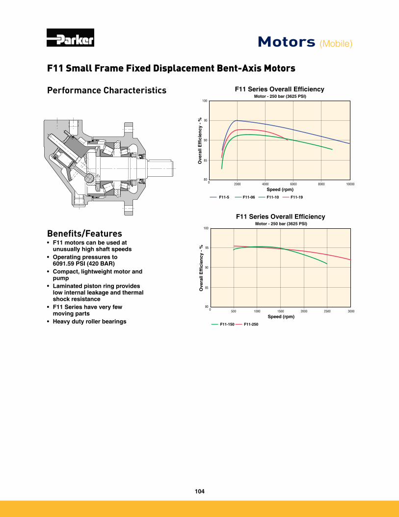
Performance Characteristics
Benefits/Features• F11 motors can be used at
unusually high shaft speeds• Operating pressures to
6091.59 PSI (420 BAR)• Compact, lightweight motor and
pump• Laminated piston ring provides
low internal leakage and thermal shock resistance
• F11 Series have very few moving parts
• Heavy duty roller bearings
Motors (Mobile)
Motor - 250 bar (3625 PSI)
Ove
rall
Eff
icie
ncy
- %
F11-150 F11-250
100
95
90
80
85
0 1500500 1000 25002000 3000
Speed (rpm)
F11 Series Overall Efficiency
Motor - 250 bar (3625 PSI)
Ove
rall
Eff
icie
ncy
- %
F11-5 F11-06
100
95
90
80
85
0 40002000 80006000 10000
Speed (rpm)
F11 Series Overall Efficiency
F11-10 F11-19
F11 Small Frame Fixed Displacement Bent-Axis Motors
104
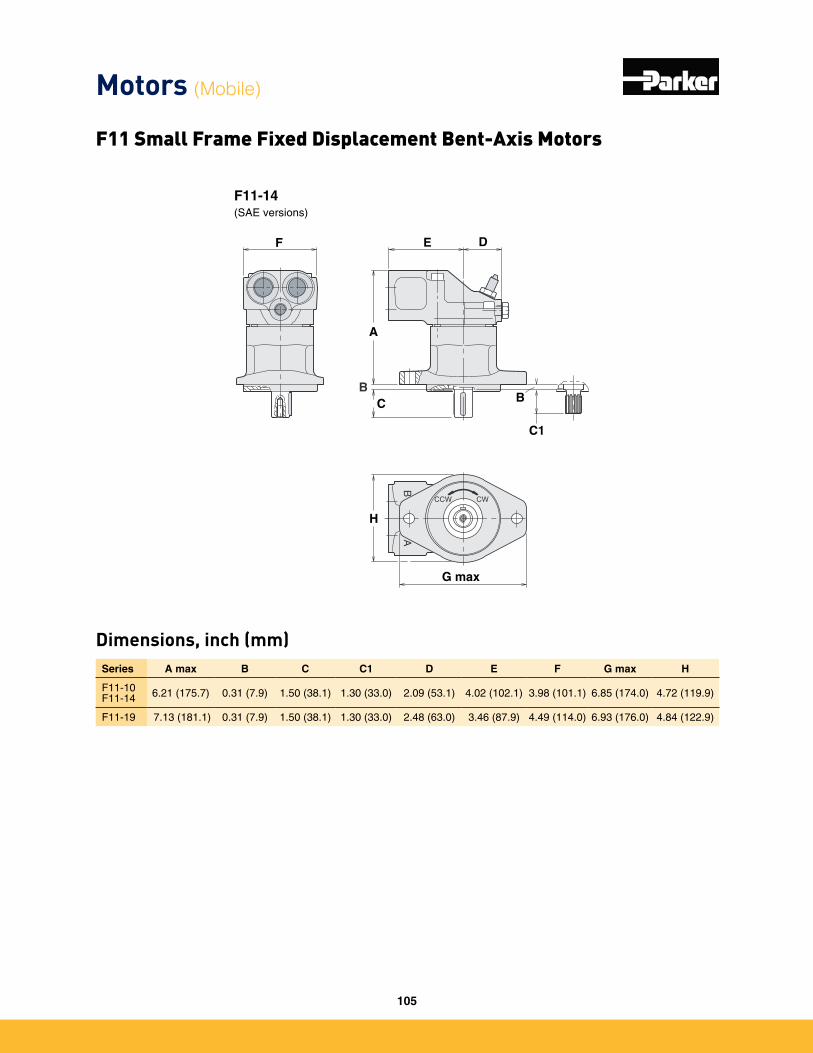
Dimensions, inch (mm)Series A max B C C1 D E F G max H
F11-10 F11-14 6�21 (175�7) 0�31 (7�9) 1�50 (38�1) 1�30 (33�0) 2�09 (53�1) 4�02 (102�1) 3�98 (101�1) 6�85 (174�0) 4�72 (119�9)
F11-19 7�13 (181�1) 0�31 (7�9) 1�50 (38�1) 1�30 (33�0) 2�48 (63�0) 3�46 (87�9) 4�49 (114�0) 6�93 (176�0) 4�84 (122�9)
Motors (Mobile)
F11 Small Frame Fixed Displacement Bent-Axis Motors F11-150(SAE version)
H max
F11-14(SAE versions)
BB
A
CCW CW
A
C
F
B
C1
E D
G max
H
A
G
B
C1
B
C
DEF max
105
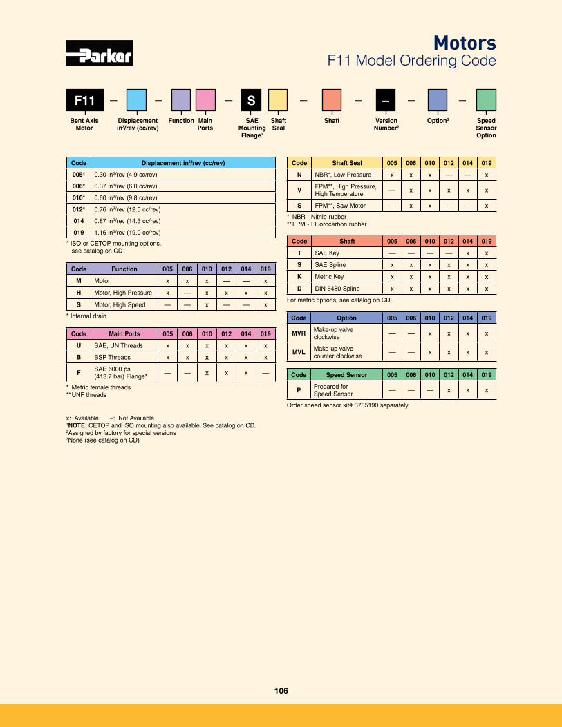
F11
Code Displacement in3/rev (cc/rev)
005* 0�30 in3/rev (4�9 cc/rev)
006* 0�37 in3/rev (6�0 cc/rev)
010* 0�60 in3/rev (9�8 cc/rev)
012* 0�76 in3/rev (12�5 cc/rev)
014 0�87 in3/rev (14�3 cc/rev)
019 1�16 in3/rev (19�0 cc/rev)
– – –– S – –– –
Code Function 005 006 010 012 014 019
M Motor x x x — — x
H Motor, High Pressure x — x x x x
S Motor, High Speed — — x — — x
* Internal drain
Code Main Ports 005 006 010 012 014 019
U SAE, UN Threads x x x x x x
B BSP Threads x x x x x x
F SAE 6000 psi (413�7 bar) Flange* — — x x x —
* Metric female threads** UNF threads
Code Shaft Seal 005 006 010 012 014 019
N NBR*, Low Pressure x x x — — x
V FPM**, High Pressure, High Temperature — x x x x x
S FPM**, Saw Motor — x x — — x
* NBR - Nitrile rubber** FPM - Fluorocarbon rubber
Code Shaft 005 006 010 012 014 019
T SAE Key — — — — x x
S SAE Spline x x x x x x
K Metric Key x x x x x x
D DIN 5480 Spline x x x x x x
For metric options, see catalog on CD�
Code Option 005 006 010 012 014 019
MVR Make-up valve clockwise — — x x x x
MVL Make-up valve counter clockwise — — x x x x
Code Speed Sensor 005 006 010 012 014 019
P Prepared for Speed Sensor — — — x x x
Order speed sensor kit# 3785190 separately
x: Available –: Not Available1NOTE: CETOP and ISO mounting also available� See catalog on CD�2Assigned by factory for special versions3None (see catalog on CD)
Displacement in3/rev (cc/rev)
Bent Axis Motor
Option3Shaft Seal
Shaft Version Number2
Main Ports
Speed Sensor Option
Function
* ISO or CETOP mounting options, see catalog on CD
MotorsF11 Model Ordering Code
SAEMounting Flange1
106
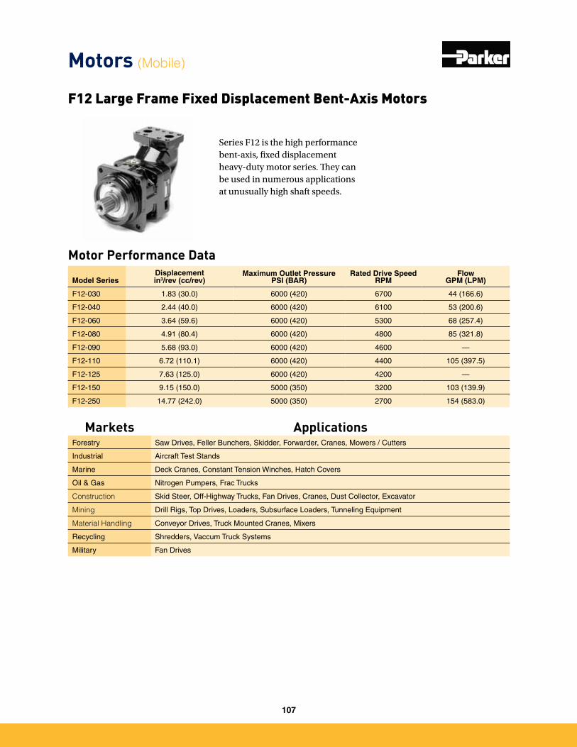
Series F12 is the high performance bent-axis, fixed displacement heavy-duty motor series. They can be used in numerous applications at unusually high shaft speeds.
Motor Performance Data
Model SeriesDisplacementin3/rev (cc/rev)
Maximum Outlet PressurePSI (BAR)
Rated Drive SpeedRPM
FlowGPM (LPM)
F12-030 1�83 (30�0) 6000 (420) 6700 44 (166�6)
F12-040 2�44 (40�0) 6000 (420) 6100 53 (200�6)
F12-060 3�64 (59�6) 6000 (420) 5300 68 (257�4)
F12-080 4�91 (80�4) 6000 (420) 4800 85 (321�8)
F12-090 5�68 (93�0) 6000 (420) 4600 —
F12-110 6�72 (110�1) 6000 (420) 4400 105 (397�5)
F12-125 7�63 (125�0) 6000 (420) 4200 —
F12-150 9�15 (150�0) 5000 (350) 3200 103 (139�9)
F12-250 14�77 (242�0) 5000 (350) 2700 154 (583�0)
F12 Large Frame Fixed Displacement Bent-Axis Motors
Motors (Mobile)
Markets ApplicationsForestry Saw Drives, Feller Bunchers, Skidder, Forwarder, Cranes, Mowers / Cutters
Industrial Aircraft Test Stands
Marine Deck Cranes, Constant Tension Winches, Hatch Covers
Oil & Gas Nitrogen Pumpers, Frac Trucks
Construction Skid Steer, Off-Highway Trucks, Fan Drives, Cranes, Dust Collector, Excavator
Mining Drill Rigs, Top Drives, Loaders, Subsurface Loaders, Tunneling Equipment
Material Handling Conveyor Drives, Truck Mounted Cranes, Mixers
Recycling Shredders, Vaccum Truck Systems
Military Fan Drives
107
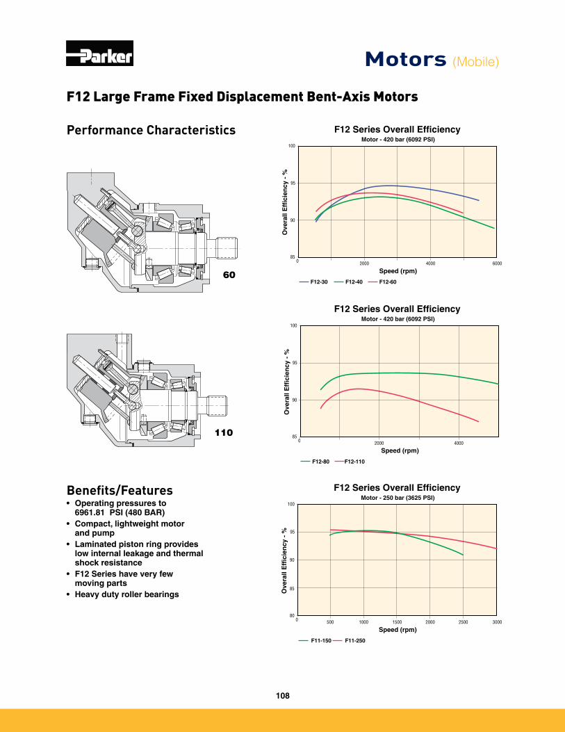
Performance Characteristics
Benefits/Features• Operating pressures to
6961.81 PSI (480 BAR)• Compact, lightweight motor
and pump• Laminated piston ring provides
low internal leakage and thermal shock resistance
• F12 Series have very few moving parts
• Heavy duty roller bearings
60
110
Motor - 420 bar (6092 PSI)
Ove
rall
Eff
icie
ncy
- %
F12-30 F12-40 F12-60
100
95
90
850 2000 4000 6000
Speed (rpm)
F12 Series Overall Efficiency
Ove
rall
Eff
icie
ncy
- %
F12-80 F12-110
100
95
90
850 2000 4000
Speed (rpm)
Motor - 420 bar (6092 PSI)
F12 Series Overall Efficiency
F12 Large Frame Fixed Displacement Bent-Axis Motors
Motors (Mobile)
Motor - 250 bar (3625 PSI)
Ove
rall
Eff
icie
ncy
- %
F11-150 F11-250
100
95
90
80
85
0 1500500 1000 25002000 3000
Speed (rpm)
F12 Series Overall Efficiency
108
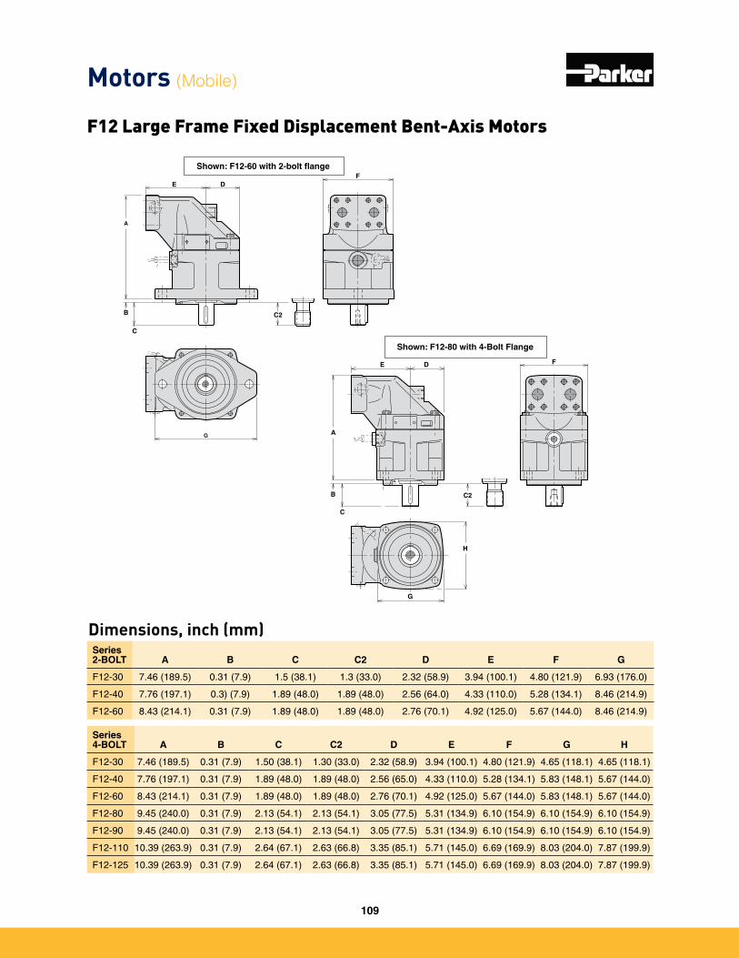
Dimensions, inch (mm)
A
C
E DF
B C2
G
Shown: F12-60 with 2-bolt flange
E
A
C
B
D F
C2
G
H
Shown: F12-80 with 4-Bolt Flange
Series 2-BOLT A B C C2 D E F G
F12-30 7�46 (189�5) 0�31 (7�9) 1�5 (38�1) 1�3 (33�0) 2�32 (58�9) 3�94 (100�1) 4�80 (121�9) 6�93 (176�0)
F12-40 7�76 (197�1) 0�3) (7�9) 1�89 (48�0) 1�89 (48�0) 2�56 (64�0) 4�33 (110�0) 5�28 (134�1) 8�46 (214�9)
F12-60 8�43 (214�1) 0�31 (7�9) 1�89 (48�0) 1�89 (48�0) 2�76 (70�1) 4�92 (125�0) 5�67 (144�0) 8�46 (214�9)
Series 4-BOLT A B C C2 D E F G H
F12-30 7�46 (189�5) 0�31 (7�9) 1�50 (38�1) 1�30 (33�0) 2�32 (58�9) 3�94 (100�1) 4�80 (121�9) 4�65 (118�1) 4�65 (118�1)
F12-40 7�76 (197�1) 0�31 (7�9) 1�89 (48�0) 1�89 (48�0) 2�56 (65�0) 4�33 (110�0) 5�28 (134�1) 5�83 (148�1) 5�67 (144�0)
F12-60 8�43 (214�1) 0�31 (7�9) 1�89 (48�0) 1�89 (48�0) 2�76 (70�1) 4�92 (125�0) 5�67 (144�0) 5�83 (148�1) 5�67 (144�0)
F12-80 9�45 (240�0) 0�31 (7�9) 2�13 (54�1) 2�13 (54�1) 3�05 (77�5) 5�31 (134�9) 6�10 (154�9) 6�10 (154�9) 6�10 (154�9)
F12-90 9�45 (240�0) 0�31 (7�9) 2�13 (54�1) 2�13 (54�1) 3�05 (77�5) 5�31 (134�9) 6�10 (154�9) 6�10 (154�9) 6�10 (154�9)
F12-110 10�39 (263�9) 0�31 (7�9) 2�64 (67�1) 2�63 (66�8) 3�35 (85�1) 5�71 (145�0) 6�69 (169�9) 8�03 (204�0) 7�87 (199�9)
F12-125 10�39 (263�9) 0�31 (7�9) 2�64 (67�1) 2�63 (66�8) 3�35 (85�1) 5�71 (145�0) 6�69 (169�9) 8�03 (204�0) 7�87 (199�9)
Motors (Mobile)
F12 Large Frame Fixed Displacement Bent-Axis Motors
109
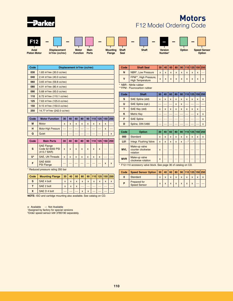
F12
Code Displacement in3/rev (cc/rev)
030 1�83 in3/rev (30�0 cc/rev)
040 2�44 in3/rev (40�0 cc/rev)
060 3�65 in3/rev (59�8 cc/rev)
080 4�91 in3/rev (80�4 cc/rev)
090 5�68 in3/rev (93�0 cc/rev)
110 6�72 in3/rev (110�1 cc/rev)
125 7�63 in3/rev (125�0 cc/rev)
150 9�15 in3/rev (150�0 cc/rev)
250 14�77 in3/rev (242�0 cc/rev)
Displacement in3/rev (cc/rev)
Axial Piston Motor
OptionMounting Flange
Shaft Seal
Shaft Version Number1
Main Ports
– – –Speed Sensor
Option
– – –– –Motor
Function
Code Main Ports 30 40 60 80 90 110 125 150 250
SSAE Flange Code 62 6000 PSI (413�7 BAR)
x x x x x x x — —
U* SAE, UN Threads x x x x x x x — —
F SAE 6000 PSI Flange — — — — — — — x x
* Reduced pressure rating 350 bar
Code Shaft Seal 30 40 60 80 90 110 125 150 250
N NBR*, Low Pressure x x x x x x x x —
V FPM**, High Pressure, High Temperature x x x x x x x x x
* NBR - Nitrile rubber** FPM - Fluorocarbon rubber
Code Mounting Flange 30 40 60 80 90 110 125 150 250
S SAE 4 bolt x x x x x x x x x
T SAE 2 bolt x x x — — — — — —
X SAE D 4 bolt — — — x x — — — —
NOTE: ISO and cartidge mounting also available� See catalog on CD�
Code Shaft 30 40 60 80 90 110 125 150 250
S SAE Spline (std) x x x x x x x x x
U SAE Spline (opt�) — — — x x — — — —
T SAE Key (std) x x x x x x x x —
K Metric Key — — — — — — — x x
F SAE Spline — — — — — — — — x
D Spline, DIN 5480 — — — — — — — — x
Code Option 30 40 60 80 90 110 125 150 250
000 Standard x x x x x x x x x
L01 Integr� Flushing Valve x x x x x —* —* — —
MVLMake-up valvecounter clockwise rotation
x — — — — — — — —
MVR Make-up valveclockwise rotation x — — — — — — — —
* F12-110 accessory valve block� See page 36 of catalog on CD�
x: Available –: Not Available1Assigned by factory for special versions2Order speed sensor kit# 3785190 separately�
MotorsF12 Model Ordering Code
Code Motor Function 30 40 60 80 90 110 125 150 250
M Motor x x x x x x x x —
H Motor-High Pressure — — — — — — — x —
Q Quiet — — — — — — — — x
Code Speed Sensor Option 30 40 60 80 90 110 125 150 250
0 Standard x x x x x x x x x
P Prepared for Speed Sensor x x x x x x x — —
110
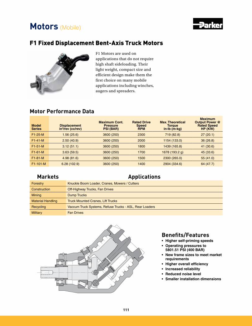
F1 Motors are used on applications that do not require high shaft sideloading. Their light weight, compact size and efficient design make them the first choice on many mobile applications including winches, augers and spreaders.
Motor Performance Data
Benefits/Features• Higher self-priming speeds• Operating pressures to
5801.51 PSI (400 BAR)• New frame sizes to meet market
requirements• Higher overall efficiency• Increased reliability• Reduced noise level• Smaller installation dimensions
F1 Fixed Displacement Bent-Axis Truck Motors
Model Series
Displacementin3/rev (cc/rev)
Maximum Cont. PressurePSI (BAR)
Rated Drive SpeedRPM
Max. Theoretical Torque
in-lb (m-kg)
Maximum Output Power @
Rated SpeedHP (KW)
F1-25-M 1�56 (25�6) 3600 (250) 2300 719 (82�8) 27 (20�1)
F1-41-M 2�50 (40�9) 3600 (250) 2000 1154 (133�0) 36 (26�8)
F1-51-M 3�12 (51�1) 3600 (250) 1800 1439 (165�8) 41 (30�6)
F1-61-M 3�63 (59�5) 3600 (250) 1700 1678 (193�2 g) 45 (33�6)
F1-81-M 4�98 (81�6) 3600 (250) 1500 2300 (265�0) 55 (41�0)
F1-101-M 6�28 (102�9) 3600 (250) 1400 2904 (334�6) 64 (47�7)
Motors (Mobile)
Markets ApplicationsForestry Knuckle Boom Loader, Cranes, Mowers / Cutters
Construction Off-Highway Trucks, Fan Drives
Mining Dump Trucks
Material Handling Truck Mounted Cranes, Lift Trucks
Recycling Vaccum Truck Systems, Refuse Trucks - ASL, Rear Loaders
Military Fan Drives
111
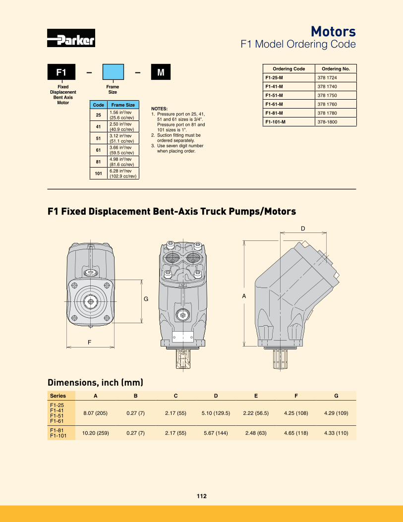
Dimensions, inch (mm)Series A B C D E F G
F1-25 F1-41 F1-51 F1-61
8�07 (205) 0�27 (7) 2�17 (55) 5�10 (129�5) 2�22 (56�5) 4�25 (108) 4�29 (109)
F1-81 F1-101 10�20 (259) 0�27 (7) 2�17 (55) 5�67 (144) 2�48 (63) 4�65 (118) 4�33 (110)
A
D
F
G
F1 MFrame Size
Fixed Displacenent
Bent Axis Motor
– –
NOTES: 1� Pressure port on 25, 41,
51 and 61 sizes is 3/4"� Pressure port on 81 and 101 sizes is 1"�
2� Suction fitting must be ordered separately�
3� Use seven digit number when placing order�
Ordering Code Ordering No.
F1-25-M 378 1724
F1-41-M 378 1740
F1-51-M 378 1750
F1-61-M 378 1760
F1-81-M 378 1780
F1-101-M 378-1800
F1 Fixed Displacement Bent-Axis Truck Pumps/Motors
MotorsF1 Model Ordering Code
Code Frame Size
25 1�56 in3/rev(25�6 cc/rev)
41 2�50 in3/rev(40�9 cc/rev)
51 3�12 in3/rev(51�1 cc/rev)
61 3�66 in3/rev(59�5 cc/rev)
81 4�98 in3/rev(81�6 cc/rev)
101 6�28 in3/rev(102�9 cc/rev)
112
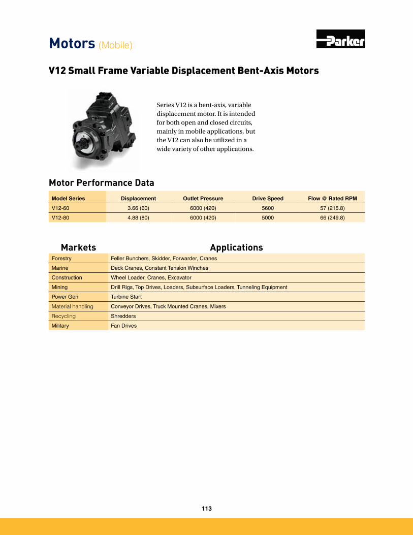
Motor Performance Data
Series V12 is a bent-axis, variable displacement motor. It is intended for both open and closed circuits, mainly in mobile applications, but the V12 can also be utilized in a wide variety of other applications.
Model Series Displacement Outlet Pressure Drive Speed Flow @ Rated RPM
V12-60 3�66 (60) 6000 (420) 5600 57 (215�8)
V12-80 4�88 (80) 6000 (420) 5000 66 (249�8)
V12 Small Frame Variable Displacement Bent-Axis Motors
Motors (Mobile)
Markets ApplicationsForestry Feller Bunchers, Skidder, Forwarder, Cranes
Marine Deck Cranes, Constant Tension Winches
Construction Wheel Loader, Cranes, Excavator
Mining Drill Rigs, Top Drives, Loaders, Subsurface Loaders, Tunneling Equipment
Power Gen Turbine Start
Material handling Conveyor Drives, Truck Mounted Cranes, Mixers
Recycling Shredders
Military Fan Drives
113
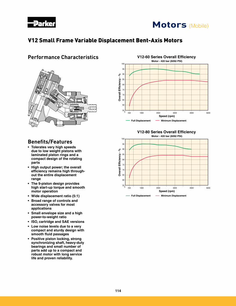
Performance Characteristics
Benefits/Features• Tolerates very high speeds
due to low weight pistons with laminated piston rings and a compact design of the rotating parts
• High output power; the overall efficiency remains high through-out the entire displacement range
• The 9-piston design provides high start-up torque and smooth motor operation
• Wide displacement ratio (5:1)• Broad range of controls and
accessory valves for most applications
• Small envelope size and a high power-to-weight ratio
• ISO, cartridge and SAE versions• Low noise levels due to a very
compact and sturdy design with smooth fluid passages
• Positive piston locking, strong synchronizing shaft, heavy-duty bearings and small number of parts add up to a compact and robust motor with long service life and proven reliability.
55
60
65
70
75
80
85
90
95
100Motor - 420 bar (6092 PSI)
Ove
rall
Eff
icie
ncy
- %
Full Displacement Minimum Displacement
0 20001000250 3000 50004000
Speed (rpm)
V12-60 Series Overall Efficiency
55
60
65
70
75
80
85
90
95
100Motor - 420 bar (6092 PSI)
Ove
rall
Eff
icie
ncy
- %
Full Displacement Minimum Displacement
0 20001000250 3000 50004000
Speed (rpm)
V12-80 Series Overall Efficiency
V12 Small Frame Variable Displacement Bent-Axis Motors
Motors (Mobile)
114
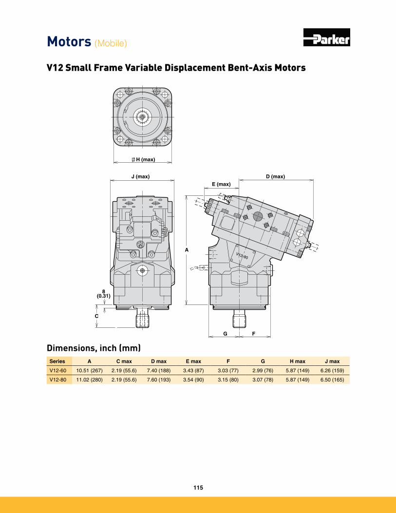
Dimensions, inch (mm)
V12-80
H (max)
D (max)E (max)
J (max)
8(0.31)
C
A
G F
Series A C max D max E max F G H max J max
V12-60 10�51 (267) 2�19 (55�6) 7�40 (188) 3�43 (87) 3�03 (77) 2�99 (76) 5�87 (149) 6�26 (159)
V12-80 11�02 (280) 2�19 (55�6) 7�60 (193) 3�54 (90) 3�15 (80) 3�07 (78) 5�87 (149) 6�50 (165)
Motors (Mobile)
V12 Small Frame Variable Displacement Bent-Axis Motors
115
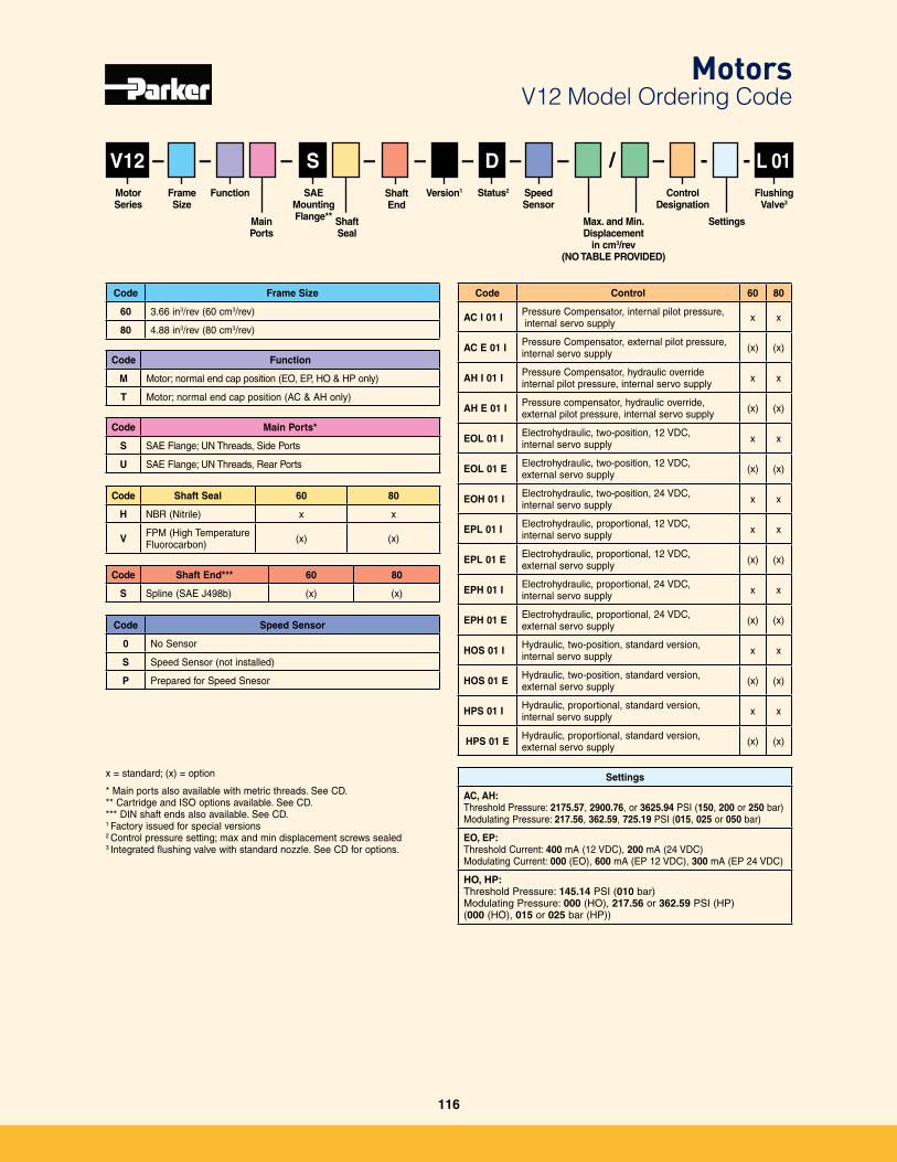
V12
Code Frame Size
60 3�66 in3/rev (60 cm3/rev)
80 4�88 in3/rev (80 cm3/rev)
Frame Size
Motor Series
Flushing Valve3
Function
Main Ports
Shaft End
SAEMounting Flange**
–Speed Sensor
Status2
– – –– /–––
Shaft Seal
Version1
Max. and Min. Displacement
in cm3/rev(NO TABLE PROVIDED)
Code Shaft Seal 60 80
H NBR (Nitrile) x x
V FPM (High Temperature Fluorocarbon) (x) (x)
Code Control 60 80
AC I 01 I Pressure Compensator, internal pilot pressure, internal servo supply x x
AC E 01 I Pressure Compensator, external pilot pressure, internal servo supply (x) (x)
AH I 01 I Pressure Compensator, hydraulic overrideinternal pilot pressure, internal servo supply x x
AH E 01 I Pressure compensator, hydraulic override,external pilot pressure, internal servo supply (x) (x)
EOL 01 I Electrohydraulic, two-position, 12 VDC, internal servo supply x x
EOL 01 E Electrohydraulic, two-position, 12 VDC, external servo supply (x) (x)
EOH 01 I Electrohydraulic, two-position, 24 VDC, internal servo supply x x
EPL 01 I Electrohydraulic, proportional, 12 VDC, internal servo supply x x
EPL 01 E Electrohydraulic, proportional, 12 VDC, external servo supply (x) (x)
EPH 01 I Electrohydraulic, proportional, 24 VDC, internal servo supply x x
EPH 01 E Electrohydraulic, proportional, 24 VDC, external servo supply (x) (x)
HOS 01 I Hydraulic, two-position, standard version, internal servo supply x x
HOS 01 E Hydraulic, two-position, standard version, external servo supply (x) (x)
HPS 01 I Hydraulic, proportional, standard version, internal servo supply x x
HPS 01 E Hydraulic, proportional, standard version, external servo supply (x) (x)
Code Shaft End*** 60 80
S Spline (SAE J498b) (x) (x)
Code Function
M Motor; normal end cap position (EO, EP, HO & HP only)
T Motor; normal end cap position (AC & AH only)
Code Main Ports*
S SAE Flange; UN Threads, Side Ports
U SAE Flange; UN Threads, Rear Ports
Code Speed Sensor
0 No Sensor
S Speed Sensor (not installed)
P Prepared for Speed Snesor
--– L 01Control
Designation
Settings
Settings
AC, AH:Threshold Pressure: 2175.57, 2900.76, or 3625.94 PSI (150, 200 or 250 bar)Modulating Pressure: 217.56, 362.59, 725.19 PSI (015, 025 or 050 bar)
EO, EP:Threshold Current: 400 mA (12 VDC), 200 mA (24 VDC)Modulating Current: 000 (EO), 600 mA (EP 12 VDC), 300 mA (EP 24 VDC)
HO, HP: Threshold Pressure: 145.14 PSI (010 bar)Modulating Pressure: 000 (HO), 217.56 or 362.59 PSI (HP) (000 (HO), 015 or 025 bar (HP))
DS
x = standard; (x) = option
* Main ports also available with metric threads� See CD�** Cartridge and ISO options available� See CD�*** DIN shaft ends also available� See CD�1 Factory issued for special versions2 Control pressure setting; max and min displacement screws sealed3 Integrated flushing valve with standard nozzle� See CD for options�
MotorsV12 Model Ordering Code
116
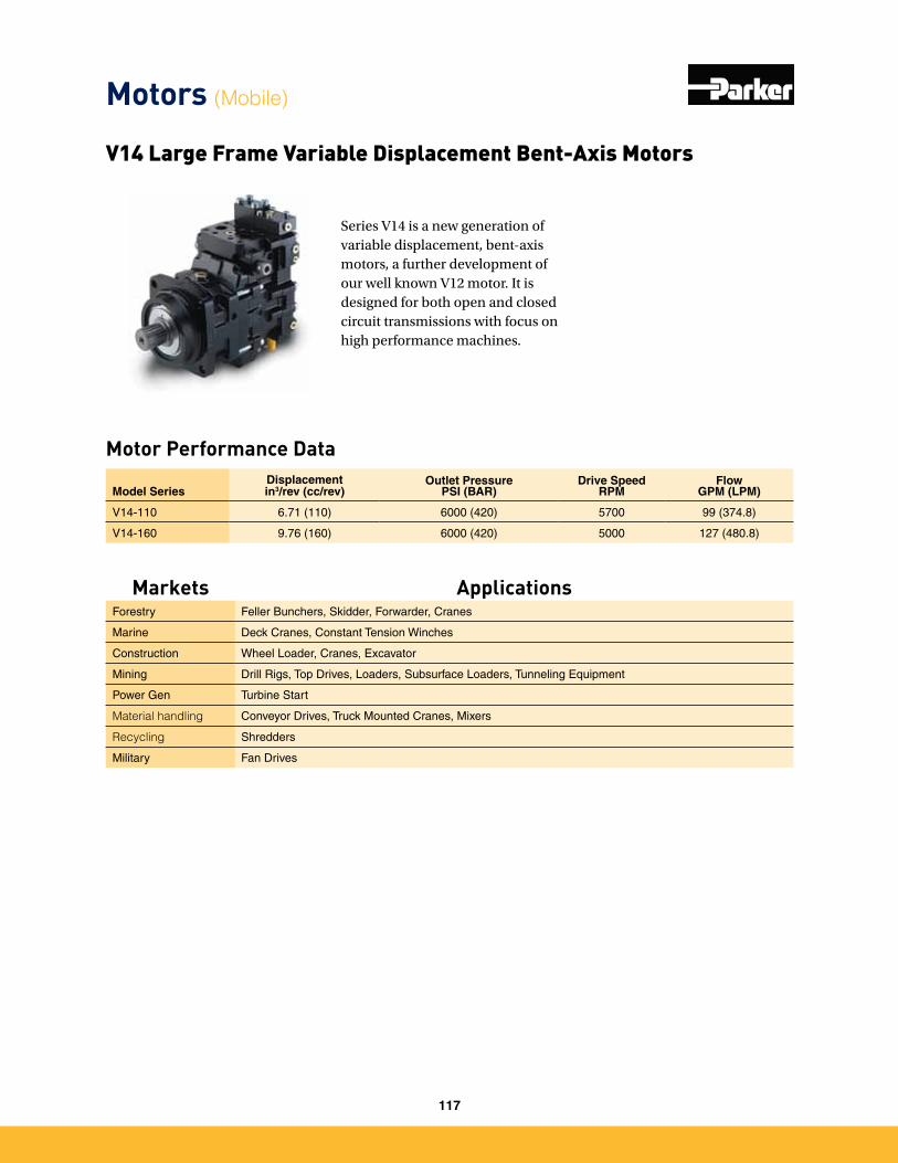
Motor Performance Data
Series V14 is a new generation of variable displacement, bent-axis motors, a further development of our well known V12 motor. It is designed for both open and closed circuit transmissions with focus on high performance machines.
Model SeriesDisplacementin3/rev (cc/rev)
Outlet PressurePSI (BAR)
Drive SpeedRPM
FlowGPM (LPM)
V14-110 6�71 (110) 6000 (420) 5700 99 (374�8)
V14-160 9�76 (160) 6000 (420) 5000 127 (480�8)
V14 Large Frame Variable Displacement Bent-Axis Motors
Motors (Mobile)
Markets ApplicationsForestry Feller Bunchers, Skidder, Forwarder, Cranes
Marine Deck Cranes, Constant Tension Winches
Construction Wheel Loader, Cranes, Excavator
Mining Drill Rigs, Top Drives, Loaders, Subsurface Loaders, Tunneling Equipment
Power Gen Turbine Start
Material handling Conveyor Drives, Truck Mounted Cranes, Mixers
Recycling Shredders
Military Fan Drives
117
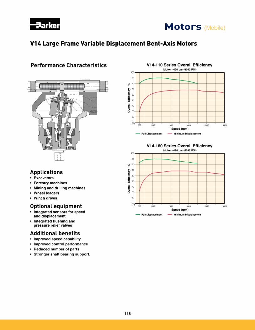
Performance Characteristics
Applications• Excavators• Forestry machines• Mining and drilling machines• Wheel loaders• Winch drives
Optional equipment• Integrated sensors for speed
and displacement• Integrated flushing and
pressure relief valves
Additional benefits• Improved speed capability• Improved control performance• Reduced number of parts• Stronger shaft bearing support.
55
60
65
70
75
80
85
90
95
100Motor - 420 bar (6092 PSI)
Ove
rall
Eff
icie
ncy
- %
Full Displacement Minimum Displacement
0 20001000250 3000 50004000
Speed (rpm)
V14-110 Series Overall Efficiency
55
60
65
70
75
80
85
90
95
100Motor - 420 bar (6092 PSI)
Ove
rall
Eff
icie
ncy
- %
Full Displacement Minimum Displacement
0 20001000250 3000 50004000
Speed (rpm)
V14-160 Series Overall Efficiency
V14 Large Frame Variable Displacement Bent-Axis Motors
Motors (Mobile)
118
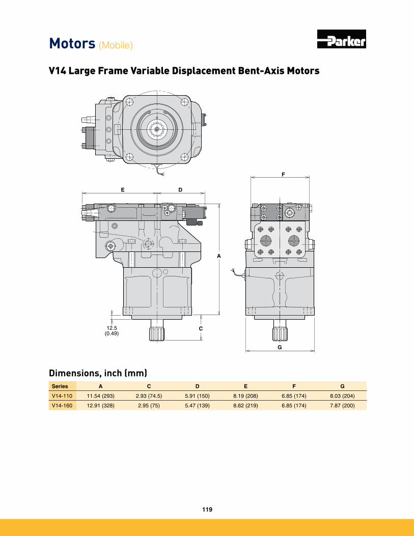
Dimensions, inch (mm)
E D
A
C12.5(0.49)
F
G
Series A C D E F G
V14-110 11�54 (293) 2�93 (74�5) 5�91 (150) 8�19 (208) 6�85 (174) 8�03 (204)
V14-160 12�91 (328) 2�95 (75) 5�47 (139) 8�62 (219) 6�85 (174) 7�87 (200)
Motors (Mobile)
V14 Large Frame Variable Displacement Bent-Axis Motors
119
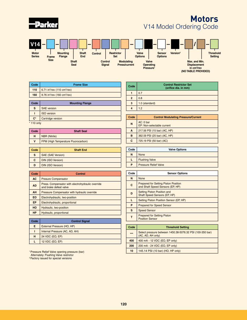
V14
Code Frame Size
110 6�71 in3/rev (110 cm3/rev)
160 9�76 in3/rev (160 cm3/rev)
Frame Size
Motor Series
Threshold Setting
Mounting Flange
Shaft Seal
Shaft End
Control Signal
–Sensor Options
Control
Code Mounting Flange
S SAE version
I ISO version
C* Cartridge version
– – –– /–––Restrictor
Set
ModulatingPress/current
Valve Options
Valve OperatingPressure1
Version2
Max. and Min. Displacement
in cm3/rev(NO TABLE PROVIDED)
Code Shaft Seal
H NBR (Nitrile)
V FPM (High Temperature Fluorocarbon)
Code Control
AC Presure Compensator
AD Press� Compensator with electrohydraulic override and brake defeat valve
AH Pressure Compensator with hydraulic override
EO Electrohydraulic, two-position
EP Electrohydraulic, proportional
HO Hydraulic, two-position
HP Hydraulic, proportional
Code Shaft End
S SAE (SAE Version)
C DIN (ISO Version)
D DIN (ISO Version)
Code Control Signal
E External Pressure (HO, HP)
I Internal Pressure (AC, AD, AH)
H 24 VDC (EO, EP)
L 12 VDC (EO, EP)
Code Control Restrictor Set (orifice dia. in mm)
1 0�7
2 0�8
3 1�0 (standard)
4 1�2
Code Control Modulating Pressure/Current
N AC: 0 bar EP: Non-selectable current
A 217�56 PSI (15 bar) (AC, HP)
B 362�59 PSI (25 bar) (AC, HP)
C 725�19 PSI (50 bar) (AC)
Code Valve Options
N None
L Flushing Valve
P Pressure Relief Valve
Code Sensor Options
N None
C Prepared for Setting Piston Position and Shaft Speed Sensors (EP, HP)
D Setting Piston Position and Shaft Speed Sensors (EP, HP)
L Setting Piston Position Sensor (EP, HP)
P Prepared for Speed Sensor
S Speed Sensor
T Prepared for Setting Piston Position Sensor
Code Threshold Setting
*** Select pressure between 1450�38-5076�32 PSI (100-350 bar) (AC, AD, AH only)
400 400 mA - 12 VDC (EO, EP only)
200 200 mA - 24 VDC (EO, EP only)
10 145�14 PSI (10 bar) (HO, HP only)
* 110 only
MotorsV14 Model Ordering Code
1 Pressure Relief Valve opening pressure (bar) Alternately: Flushing Valve restrictor2 Factory issued for special versions
120
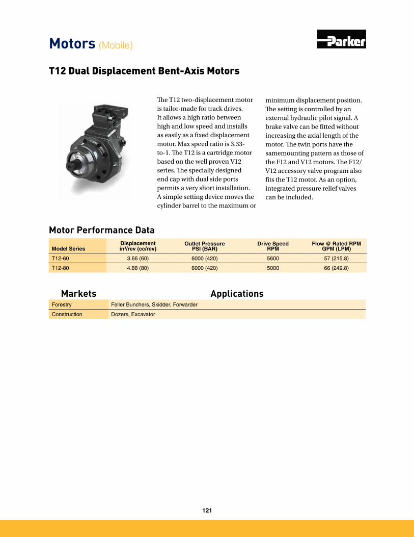
Motor Performance Data
The T12 two-displacement motor is tailor-made for track drives. It allows a high ratio between high and low speed and installs as easily as a fixed displacement motor. Max speed ratio is 3.33-to-1. The T12 is a cartridge motor based on the well proven V12 series. The specially designed end cap with dual side ports permits a very short installation. A simple setting device moves the cylinder barrel to the maximum or
minimum displacement position. The setting is controlled by an external hydraulic pilot signal. A brake valve can be fitted without increasing the axial length of the motor. The twin ports have the samemounting pattern as those of the F12 and V12 motors. The F12/V12 accessory valve program also fits the T12 motor. As an option, integrated pressure relief valves can be included.
Model SeriesDisplacementin3/rev (cc/rev)
Outlet PressurePSI (BAR)
Drive SpeedRPM
Flow @ Rated RPM GPM (LPM)
T12-60 3�66 (60) 6000 (420) 5600 57 (215�8)
T12-80 4�88 (80) 6000 (420) 5000 66 (249�8)
T12 Dual Displacement Bent-Axis Motors
Motors (Mobile)
Markets ApplicationsForestry Feller Bunchers, Skidder, Forwarder
Construction Dozers, Excavator
121
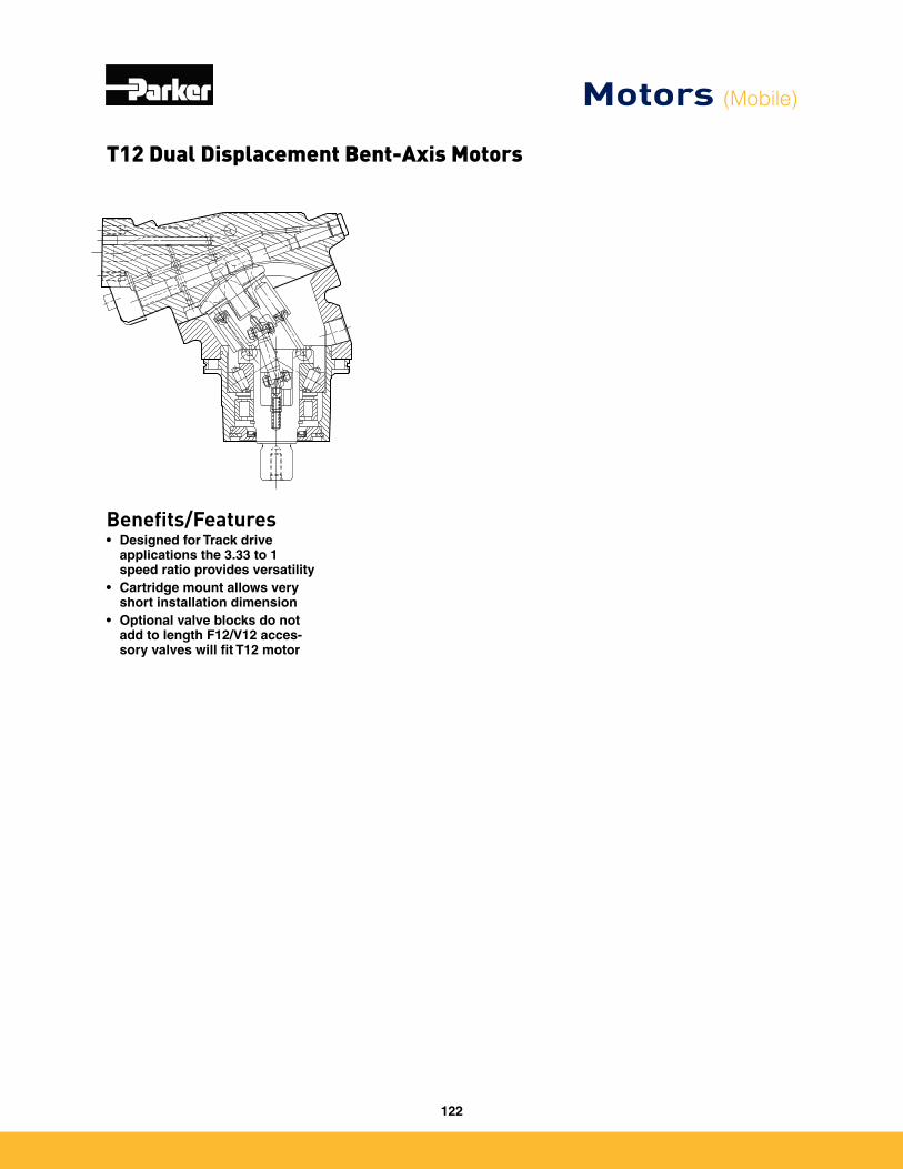
Benefits/Features• Designed for Track drive
applications the 3.33 to 1 speed ratio provides versatility
• Cartridge mount allows very short installation dimension
• Optional valve blocks do not add to length F12/V12 acces-sory valves will fit T12 motor
T12 Dual Displacement Bent-Axis Motors
Motors (Mobile)
122
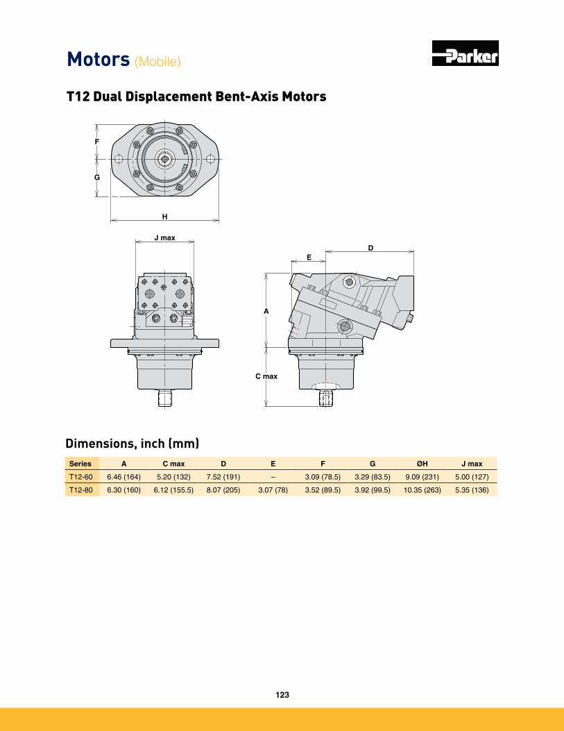
Dimensions, inch (mm)Series A C max D E F G ØH J max
T12-60 6�46 (164) 5�20 (132) 7�52 (191) – 3�09 (78�5) 3�29 (83�5) 9�09 (231) 5�00 (127)
T12-80 6�30 (160) 6�12 (155�5) 8�07 (205) 3�07 (78) 3�52 (89�5) 3�92 (99�5) 10�35 (263) 5�35 (136)
J maxD
E
A
C max
H
F
G
Motors (Mobile)
T12 Dual Displacement Bent-Axis Motors
123
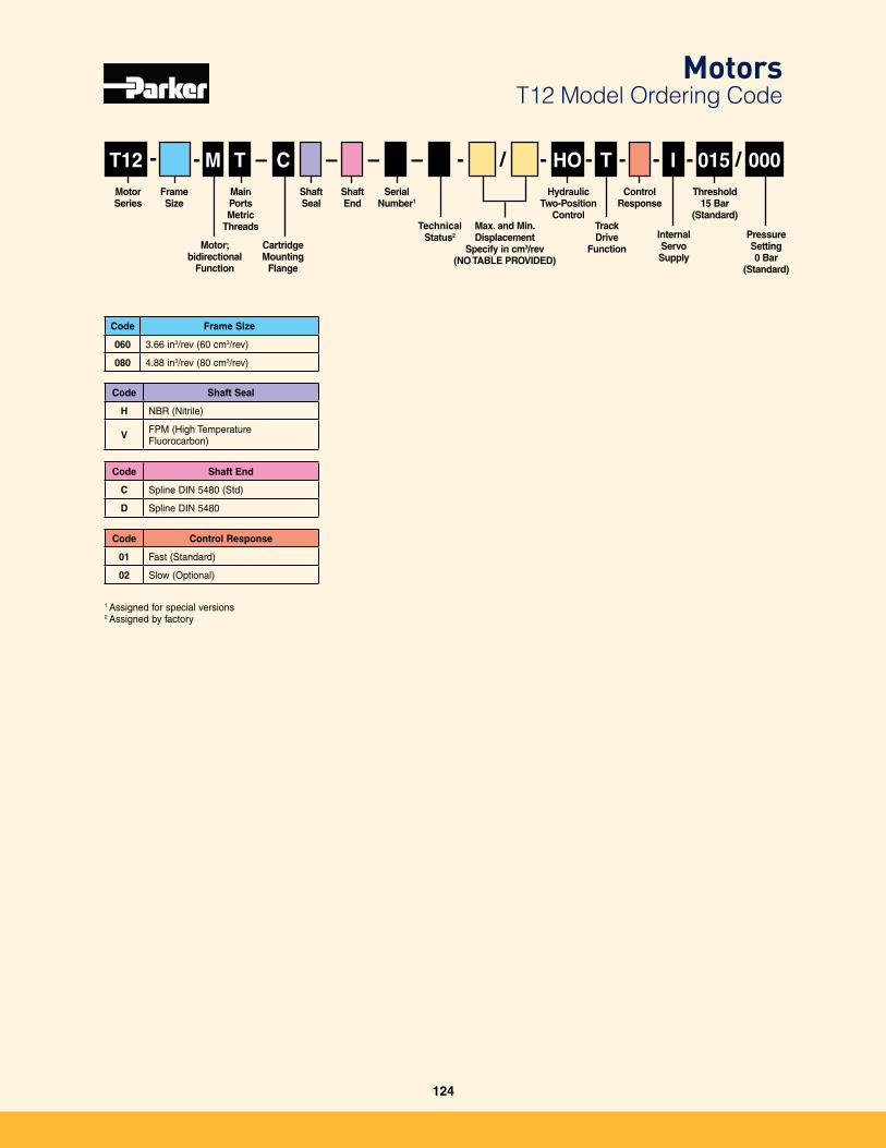
Threshold15 Bar
(Standard)Max. and Min. Displacement
Specify in cm3/rev(NO TABLE PROVIDED)
T12
Code Frame Size
060 3�66 in3/rev (60 cm3/rev)
080 4�88 in3/rev (80 cm3/rev)
- - – -- /–––
Code Shaft Seal
H NBR (Nitrile)
V FPM (High Temperature Fluorocarbon)
Code Shaft End
C Spline DIN 5480 (Std)
D Spline DIN 5480
---M T C HO T -I /015 000
Code Control Response
01 Fast (Standard)
02 Slow (Optional)
Frame Size
Motor Series
Pressure Setting0 Bar
(Standard)
Motor; bidirectional
Function
Main PortsMetric
Threads
Shaft End
CartridgeMounting
Flange
Control Response
TechnicalStatus2
Shaft Seal
Serial Number1
Hydraulic Two-Position
Control
InternalServo Supply
TrackDrive
Function
MotorsT12 Model Ordering Code
1 Assigned for special versions2 Assigned by factory
124
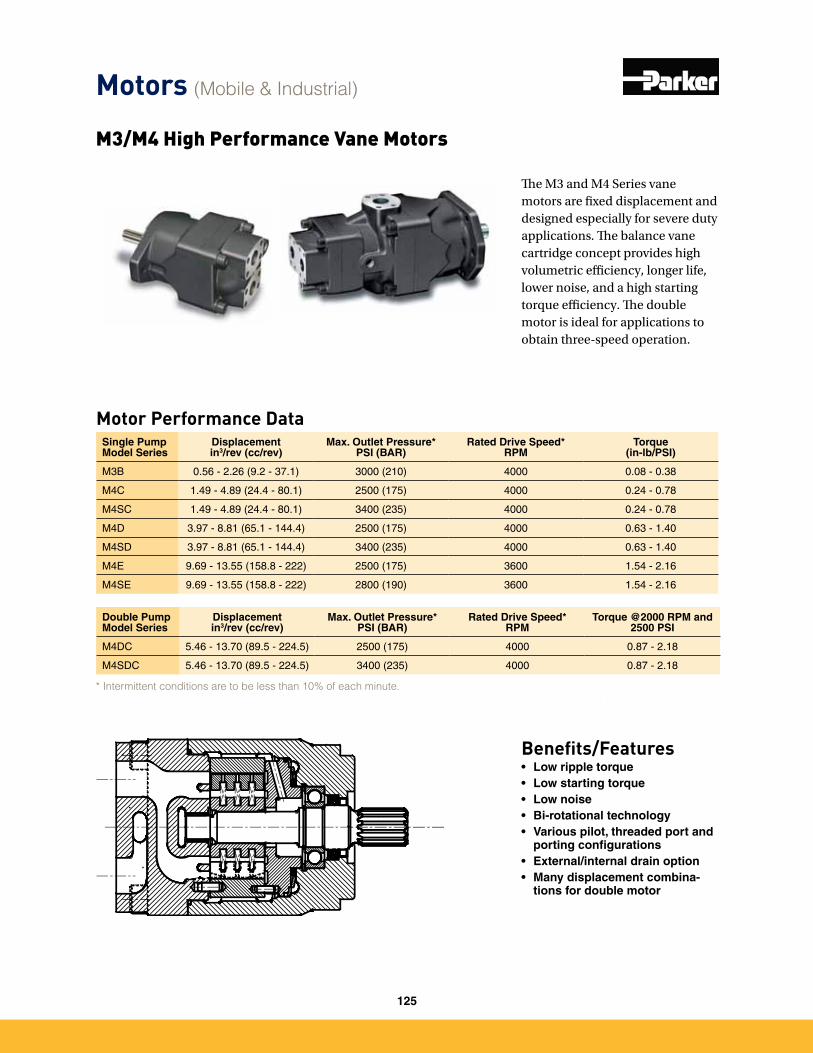
M3/M4 High Performance Vane Motors
Motor Performance DataSingle Pump Model Series
Displacement in3/rev (cc/rev)
Max. Outlet Pressure*PSI (BAR)
Rated Drive Speed*RPM
Torque (in-lb/PSI)
M3B 0�56 - 2�26 (9�2 - 37�1) 3000 (210) 4000 0�08 - 0�38
M4C 1�49 - 4�89 (24�4 - 80�1) 2500 (175) 4000 0�24 - 0�78
M4SC 1�49 - 4�89 (24�4 - 80�1) 3400 (235) 4000 0�24 - 0�78
M4D 3�97 - 8�81 (65�1 - 144�4) 2500 (175) 4000 0�63 - 1�40
M4SD 3�97 - 8�81 (65�1 - 144�4) 3400 (235) 4000 0�63 - 1�40
M4E 9�69 - 13�55 (158�8 - 222) 2500 (175) 3600 1�54 - 2�16
M4SE 9�69 - 13�55 (158�8 - 222) 2800 (190) 3600 1�54 - 2�16
Double Pump Model Series
Displacement in3/rev (cc/rev)
Max. Outlet Pressure*PSI (BAR)
Rated Drive Speed*RPM
Torque @2000 RPM and 2500 PSI
M4DC 5�46 - 13�70 (89�5 - 224�5) 2500 (175) 4000 0�87 - 2�18
M4SDC 5�46 - 13�70 (89�5 - 224�5) 3400 (235) 4000 0�87 - 2�18
Benefits/Features• Low ripple torque• Low starting torque• Low noise• Bi-rotational technology• Various pilot, threaded port and
porting configurations• External/internal drain option• Many displacement combina-
tions for double motor
The M3 and M4 Series vane motors are fixed displacement and designed especially for severe duty applications. The balance vane cartridge concept provides high volumetric efficiency, longer life, lower noise, and a high starting torque efficiency. The double motor is ideal for applications to obtain three-speed operation.
* Intermittent conditions are to be less than 10% of each minute.
Motors (Mobile & Industrial)
125
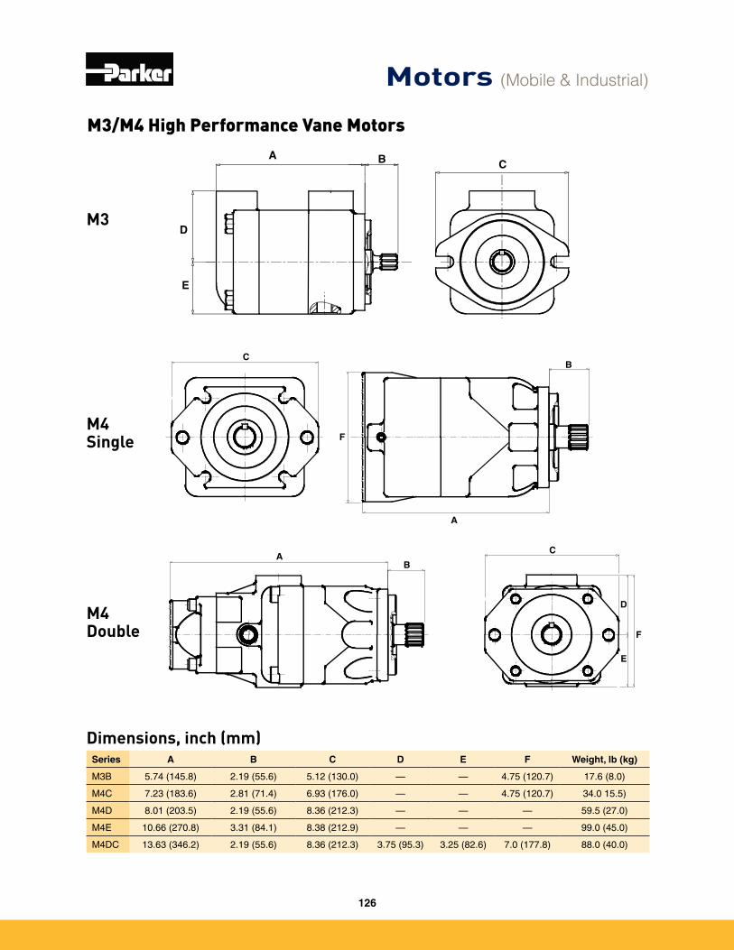
Dimensions, inch (mm)
M3
M4 Single
Series A B C D E F Weight, lb (kg)
M3B 5�74 (145�8) 2�19 (55�6) 5�12 (130�0) — — 4�75 (120�7) 17�6 (8�0)
M4C 7�23 (183�6) 2�81 (71�4) 6�93 (176�0) — — 4�75 (120�7) 34�0 15�5)
M4D 8�01 (203�5) 2�19 (55�6) 8�36 (212�3) — — — 59�5 (27�0)
M4E 10�66 (270�8) 3�31 (84�1) 8�38 (212�9) — — — 99�0 (45�0)
M4DC 13�63 (346�2) 2�19 (55�6) 8�36 (212�3) 3�75 (95�3) 3�25 (82�6) 7�0 (177�8) 88�0 (40�0)
A B
D
E
C
A
BC
F
C
D
E
F
BA
M4 Double
M3/M4 High Performance Vane Motors
Motors (Mobile & Industrial)
126
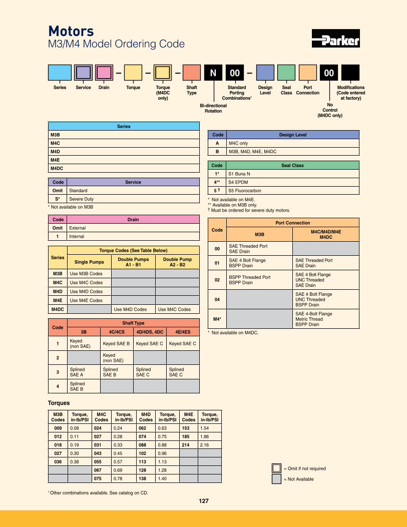
Motors M3/M4 Model Ordering Code
Series
M3B
M4C
M4D
M4E
M4DCCode Seal Class
1* S1 Buna N
4** S4 EPDM
5 † S5 Fluorocarbon
* Not available on M4E�** Available on M3B only�† Must be ordered for severe duty motors�
Series PortConnection
StandardPorting
Combinations1
Design Level
Seal Class
ShaftType
CodeShaft Type
3B 4C/4CS 4D/4DS, 4DC 4E/4ES
1 Keyed (non SAE) Keyed SAE B Keyed SAE C Keyed SAE C
2 Keyed (non SAE)
3 Splined SAE A
Splined SAE B
Splined SAE C
Splined SAE C
4 Splined SAE B
M3BCodes
Torque, in-lb/PSI
M4C Codes
Torque, in-lb/PSI
M4D Codes
Torque, in-lb/PSI
M4E Codes
Torque, in-lb/PSI
009 0�08 024 0�24 062 0�63 153 1�54
012 0�11 027 0�28 074 0�75 185 1�86
018 0�19 031 0�33 088 0�88 214 2�16
027 0�30 043 0�45 102 0�96
036 0�38 055 0�57 113 1�13
067 0�69 128 1�28
075 0�78 138 1�40
Modifications(Code entered
at factory)
Drain
Code Service
Omit Standard
S* Severe Duty
* Not available on M3B
Code Drain
Omit External
1 Internal
Service
Code Design Level
A M4C only
B M3B, M4D, M4E, M4DC
Code
Port Connection
M3B M4C/M4D/M4EM4DC
00 SAE Threaded PortSAE Drain
01 SAE 4 Bolt FlangeBSPP Drain
SAE Threaded PortSAE Drain
02 BSPP Threaded PortBSPP Drain
SAE 4 Bolt FlangeUNC ThreadedSAE Drain
04SAE 4 Bolt FlangeUNC ThreadedBSPP Drain
M4*SAE 4-Bolt FlangeMetric ThreadBSPP Drain
* Not available on M4DC�
= Not Available
= Omit if not required
Series
Torque Codes (See Table Below)
Single Pumps Double PumpsA1 - B1
Double PumpA2 - B2
M3B Use M3B Codes
M4C Use M4C Codes
M4D Use M4D Codes
M4E Use M4E Codes
M4DC Use M4D Codes Use M4C Codes
Torques
– – 0000N––
No Control
(M4DC only)
Torque Torque(M4DConly)
1 Other combinations available� See catalog on CD�
Bi-directionalRotation
127
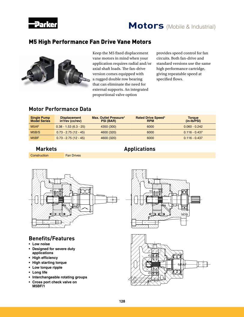
M5 High Performance Fan Drive Vane Motors
Motor Performance DataSingle Pump Model Series
Displacement in3/rev (cc/rev)
Max. Outlet Pressure*PSI (BAR)
Rated Drive Speed*RPM
Torque (in-lb/PSI)
M5AF 0�38 - 1�53 (6�3 - 25) 4350 (300) 6000 0�060 - 0�242
M5B/S 0�73 - 2�75 (12 - 45) 4600 (320) 6000 0�116 - 0�437
M5BF 0�73 - 2�75 (12 - 45) 4600 (320) 6000 0�116 - 0�437
Benefits/Features• Low noise• Designed for severe duty
applications• High efficiency• High starting torque• Low torque ripple• Long life• Interchangeable rotating groups• Cross port check valve on
M5BF/1
M5BF
M5B
M5AF
Keep the M5 fixed displacement vane motors in mind when your application requires radial and/or axial shaft loads. The fan-drive version comes equipped with a rugged double row bearing that can eliminate the need for external supports. An integrated proportional valve option
provides speed control for fan circuits. Both fan-drive and standard versions use the same high performance cartridge, giving repeatable speed at specified flows.
Motors (Mobile & Industrial)
Markets ApplicationsConstruction Fan Drives
128
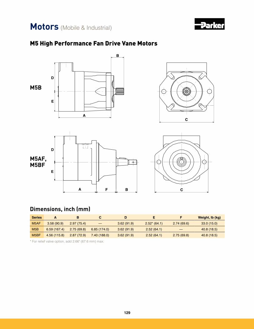
Dimensions, inch (mm)Series A B C D E F Weight, lb (kg)
M5AF 3�58 (90�9) 2�97 (75�4) — 3�62 (91�9) 2�52* (64�1) 2�74 (69�6) 33�0 (15�0)
M5B 6�59 (167�4) 2�75 (69�8) 6�85 (174�0) 3�62 (91�9) 2�52 (64�1) — 40�8 (18�5)
M5BF 4�56 (115�8) 2�87 (72�9) 7�40 (188�0) 3�62 (91�9) 2�52 (64�1) 2�75 (69�8) 40�8 (18�5)
* For relief valve option, add 2.66" (67.6 mm) max.
M5 High Performance Fan Drive Vane Motors
D
E
A
B
C
CA BF
D
E
M5B
M5AF, M5BF
Motors (Mobile & Industrial)
129
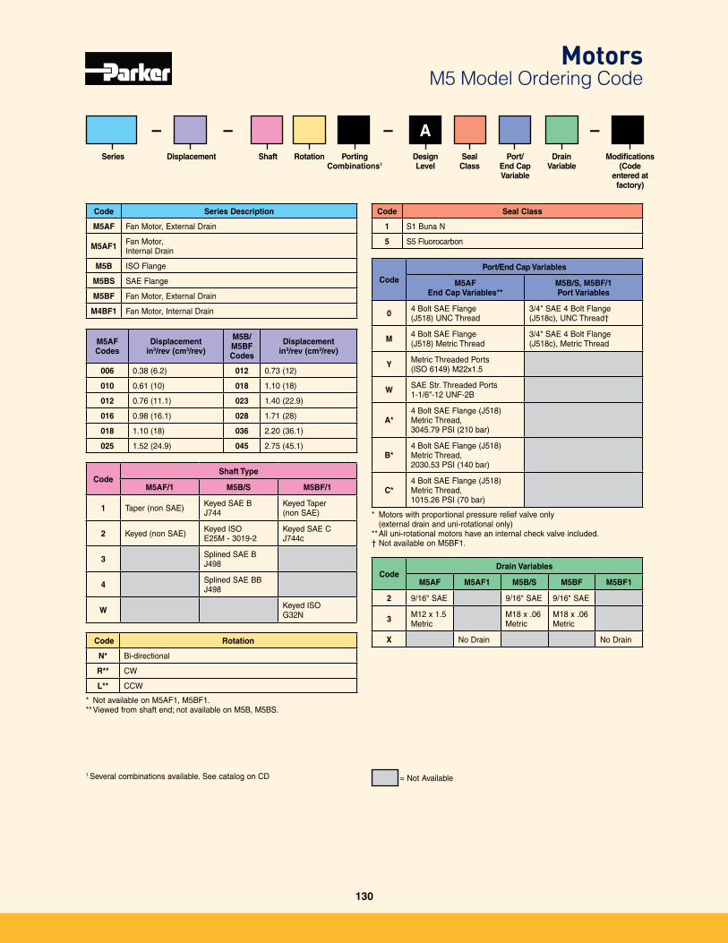
Code Rotation
N* Bi-directional
R** CW
L** CCW
* Not available on M5AF1, M5BF1�** Viewed from shaft end; not available on M5B, M5BS�
Code Series Description
M5AF Fan Motor, External Drain
M5AF1 Fan Motor,Internal Drain
M5B ISO Flange
M5BS SAE Flange
M5BF Fan Motor, External Drain
M4BF1 Fan Motor, Internal Drain
Code Seal Class
1 S1 Buna N
5 S5 Fluorocarbon
Series Port/End CapVariable
Rotation PortingCombinations1
Design Level
Seal Class
Shaft
CodeShaft Type
M5AF/1 M5B/S M5BF/1
1 Taper (non SAE) Keyed SAE B J744
Keyed Taper (non SAE)
2 Keyed (non SAE) Keyed ISOE25M - 3019-2
Keyed SAE CJ744c
3 Splined SAE BJ498
4 Splined SAE BBJ498
W Keyed ISOG32N
M5AFCodes
Displacement in3/rev (cm3/rev)
M5B/M5BF Codes
Displacementin3/rev (cm3/rev)
006 0�38 (6�2) 012 0�73 (12)
010 0�61 (10) 018 1�10 (18)
012 0�76 (11�1) 023 1�40 (22�9)
016 0�98 (16�1) 028 1�71 (28)
018 1�10 (18) 036 2�20 (36�1)
025 1�52 (24�9) 045 2�75 (45�1)
Modifications(Code
entered at factory)
Code
Port/End Cap Variables
M5AFEnd Cap Variables**
M5B/S, M5BF/1Port Variables
0 4 Bolt SAE Flange(J518) UNC Thread
3/4" SAE 4 Bolt Flange (J518c), UNC Thread†
M 4 Bolt SAE Flange(J518) Metric Thread
3/4" SAE 4 Bolt Flange(J518c), Metric Thread
Y Metric Threaded Ports(ISO 6149) M22x1�5
W SAE Str� Threaded Ports 1-1/6"-12 UNF-2B
A*4 Bolt SAE Flange (J518) Metric Thread, 3045�79 PSI (210 bar)
B*4 Bolt SAE Flange (J518)Metric Thread, 2030�53 PSI (140 bar)
C*4 Bolt SAE Flange (J518)Metric Thread, 1015�26 PSI (70 bar)
* Motors with proportional pressure relief valve only (external drain and uni-rotational only)
** All uni-rotational motors have an internal check valve included�† Not available on M5BF1�
= Not Available
– – A–Drain
VariableDisplacement
–
CodeDrain Variables
M5AF M5AF1 M5B/S M5BF M5BF1
2 9/16" SAE 9/16" SAE 9/16" SAE
3 M12 x 1�5 Metric
M18 x �06 Metric
M18 x �06 Metric
X No Drain No Drain
MotorsM5 Model Ordering Code
1 Several combinations available� See catalog on CD
130
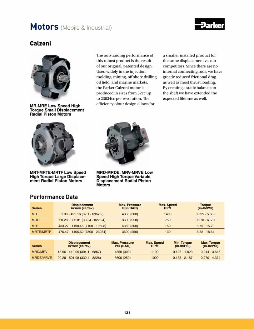
Calzoni
MR-MRE Low Speed High Torque Small Displacement Radial Piston Motors
MRT-MRTE-MRTF Low Speed High Torque Large Displace-ment Radial Piston Motors
MRD-MRDE, MRV-MRVE Low Speed High Torque Variable Displacement Radial Piston Motors
The outstanding performance of this robust product is the result of our original, patented design. Used widely in the injection molding, mining, off shore drilling, oil field, and marine markets, the Parker Calzoni motor is produced in sizes from 32cc up to 23034cc per revolution. The efficiency ofour design allows for
SeriesDisplacementin3/rev (cc/rev)
Max. PressurePSI (BAR)
Max. SpeedRPM
Torque (in-lb/PSI)
MR 1�96 - 425�16 (32�1 - 6967�2) 4350 (300) 1400 0�025 - 5�665
MRE 20�28 - 502�01 (332�4 - 8226�4) 3600 (250) 750 0�270 - 6�657
MRT 433�27 - 1190�45 (7100 - 19508) 4350 (300) 150 5�75 - 15�79
MRTE/MRTF 476�47 - 1405�62 (7808 - 23034) 3600 (250) 130 6�32 - 18�64
SeriesDisplacementin3/rev (cc/rev)
Max. PressurePSI (BAR)
Max. SpeedRPM
Min. Torque (in-lb/PSI)
Max. Torque (in-lb/PSI)
MRD/MRV 18�56 - 419�05 (304�1 - 6867) 4350 (300) 1100 0�123 - 1�823 0�244 - 3�646
MRDE/MRVE 20�28 - 501�98 (332�4 - 8226) 3600 (250) 1000 0�135 - 2�187 0�270 - 4�374
a smaller installed product for the same displacement vs. our competitors. Since there are no internal connecting rods, we have greatly reduced frictional drag as well as most thrust loading. By creating a static balance on the shaft we have extended the expected lifetime as well.
Performance Data
Motors (Mobile & Industrial)
131
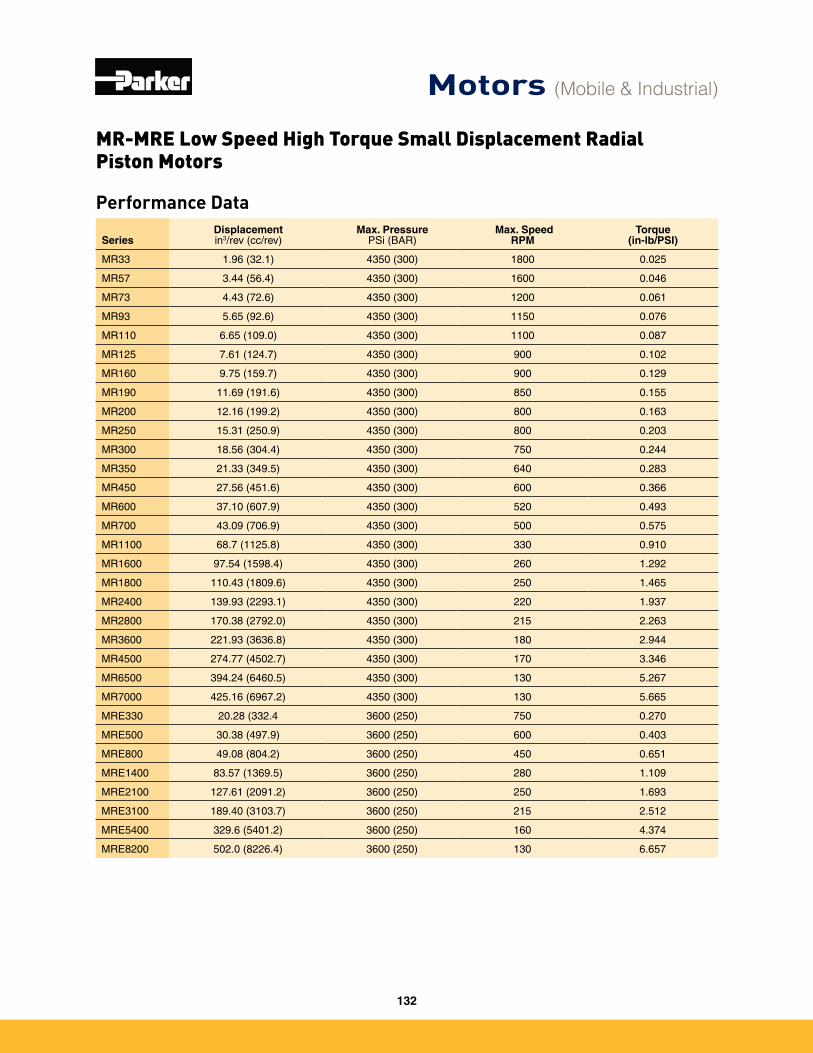
Performance Data
SeriesDisplacementin3/rev (cc/rev)
Max. PressurePSi (BAR)
Max. SpeedRPM
Torque (in-lb/PSI)
MR33 1�96 (32�1) 4350 (300) 1800 0�025
MR57 3�44 (56�4) 4350 (300) 1600 0�046
MR73 4�43 (72�6) 4350 (300) 1200 0�061
MR93 5�65 (92�6) 4350 (300) 1150 0�076
MR110 6�65 (109�0) 4350 (300) 1100 0�087
MR125 7�61 (124�7) 4350 (300) 900 0�102
MR160 9�75 (159�7) 4350 (300) 900 0�129
MR190 11�69 (191�6) 4350 (300) 850 0�155
MR200 12�16 (199�2) 4350 (300) 800 0�163
MR250 15�31 (250�9) 4350 (300) 800 0�203
MR300 18�56 (304�4) 4350 (300) 750 0�244
MR350 21�33 (349�5) 4350 (300) 640 0�283
MR450 27�56 (451�6) 4350 (300) 600 0�366
MR600 37�10 (607�9) 4350 (300) 520 0�493
MR700 43�09 (706�9) 4350 (300) 500 0�575
MR1100 68�7 (1125�8) 4350 (300) 330 0�910
MR1600 97�54 (1598�4) 4350 (300) 260 1�292
MR1800 110�43 (1809�6) 4350 (300) 250 1�465
MR2400 139�93 (2293�1) 4350 (300) 220 1�937
MR2800 170�38 (2792�0) 4350 (300) 215 2�263
MR3600 221�93 (3636�8) 4350 (300) 180 2�944
MR4500 274�77 (4502�7) 4350 (300) 170 3�346
MR6500 394�24 (6460�5) 4350 (300) 130 5�267
MR7000 425�16 (6967�2) 4350 (300) 130 5�665
MRE330 20�28 (332�4 3600 (250) 750 0�270
MRE500 30�38 (497�9) 3600 (250) 600 0�403
MRE800 49�08 (804�2) 3600 (250) 450 0�651
MRE1400 83�57 (1369�5) 3600 (250) 280 1�109
MRE2100 127�61 (2091�2) 3600 (250) 250 1�693
MRE3100 189�40 (3103�7) 3600 (250) 215 2�512
MRE5400 329�6 (5401�2) 3600 (250) 160 4�374
MRE8200 502�0 (8226�4) 3600 (250) 130 6�657
MR-MRE Low Speed High Torque Small Displacement Radial Piston Motors
Motors (Mobile & Industrial)
132
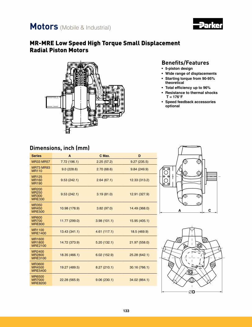
Dimensions, inch (mm)Series A C Max. D
MR33 MR57 7�72 (196�1) 2�25 (57�2) 9�27 (235�5)
MR73 MR93 MR110 9�0 (228�6) 2�70 (68�6) 9�84 (249�9)
MR125 MR160 MR190
9�53 (242�1) 2�64 (67�1) 12�33 (313�2)
MR200 MR250 MR300 MRE330
9�53 (242�1) 3�19 (81�0) 12�91 (327�9)
MR350 MR450 MRE500
10�98 (178�9) 3�82 (97�0) 14�49 (368�0)
MR600 MR700 MRE800
11�77 (299�0) 3�98 (101�1) 15�95 (405�1)
MR1100 MRE1400 13�43 (341�1) 4�61 (117�1) 18�5 (469�9)
MR1600 MR1800 MRE2100
14�72 (373�9) 5�20 (132�1) 21�97 (558�0)
MR2400 MR2800 MRE3100
18�35 (466�1) 6�02 (152�9) 25�28 (642�1)
MR3600 MR4500 MRE5400
19�27 (489�5) 8�27 (210�1) 30�16 (766�1)
MR6500 MR7000 MRE8200
22�28 (565�9) 9�06 (230�1) 34�02 (864�1)
Benefits/Features• 5-piston design• Wide range of displacements• Starting torque from 90-95%
theoretical• Total efficiency up to 96%• Resistance to thermal shocks
ΔT = 176°F• Speed feedback accessories
optional
∅DA C
∅DA C
Motors (Mobile & Industrial)
MR-MRE Low Speed High Torque Small Displacement Radial Piston Motors
133
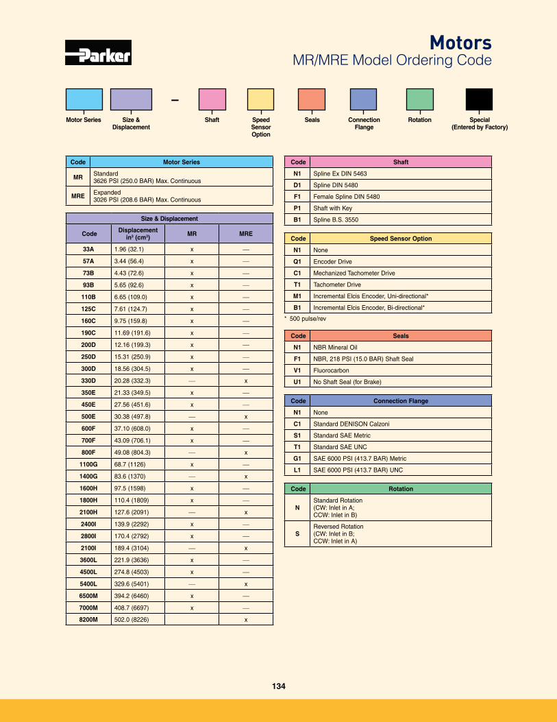
Code Motor Series
MR Standard 3626 PSI (250�0 BAR) Max� Continuous
MRE Expanded 3026 PSI (208�6 BAR) Max� Continuous
Size & Displacement
Motor Series Special(Entered by Factory)
Connection Flange
SealsShaft
–Speed Sensor Option
Code Rotation
N Standard Rotation(CW: Inlet in A; CCW: Inlet in B)
SReversed Rotation(CW: Inlet in B; CCW: Inlet in A)
Code Connection Flange
N1 None
C1 Standard DENISON Calzoni
S1 Standard SAE Metric
T1 Standard SAE UNC
G1 SAE 6000 PSI (413�7 BAR) Metric
L1 SAE 6000 PSI (413�7 BAR) UNC
Code Seals
N1 NBR Mineral Oil
F1 NBR, 218 PSI (15�0 BAR) Shaft Seal
V1 Fluorocarbon
U1 No Shaft Seal (for Brake)
Size & Displacement
Code Displacement in3 (cm3) MR MRE
33A 1�96 (32�1) x —
57A 3�44 (56�4) x —
73B 4�43 (72�6) x —
93B 5�65 (92�6) x —
110B 6�65 (109�0) x —
125C 7�61 (124�7) x —
160C 9�75 (159�8) x —
190C 11�69 (191�6) x —
200D 12�16 (199�3) x —
250D 15�31 (250�9) x —
300D 18�56 (304�5) x —
330D 20�28 (332�3) — x
350E 21�33 (349�5) x —
450E 27�56 (451�6) x —
500E 30�38 (497�8) — x
600F 37�10 (608�0) x —
700F 43�09 (706�1) x —
800F 49�08 (804�3) — x
1100G 68�7 (1126) x —
1400G 83�6 (1370) — x
1600H 97�5 (1598) x —
1800H 110�4 (1809) x —
2100H 127�6 (2091) — x
2400I 139�9 (2292) x —
2800I 170�4 (2792) x —
2100I 189�4 (3104) — x
3600L 221�9 (3636) x —
4500L 274�8 (4503) x —
5400L 329�6 (5401) — x
6500M 394�2 (6460) x —
7000M 408�7 (6697) x —
8200M 502�0 (8226) x
Code Speed Sensor Option
N1 None
Q1 Encoder Drive
C1 Mechanized Tachometer Drive
T1 Tachometer Drive
M1 Incremental Elcis Encoder, Uni-directional*
B1 Incremental Elcis Encoder, Bi-directional*
* 500 pulse/rev
Code Shaft
N1 Spline Ex DIN 5463
D1 Spline DIN 5480
F1 Female Spline DIN 5480
P1 Shaft with Key
B1 Spline B�S� 3550
MotorsMR/MRE Model Ordering Code
Rotation
134
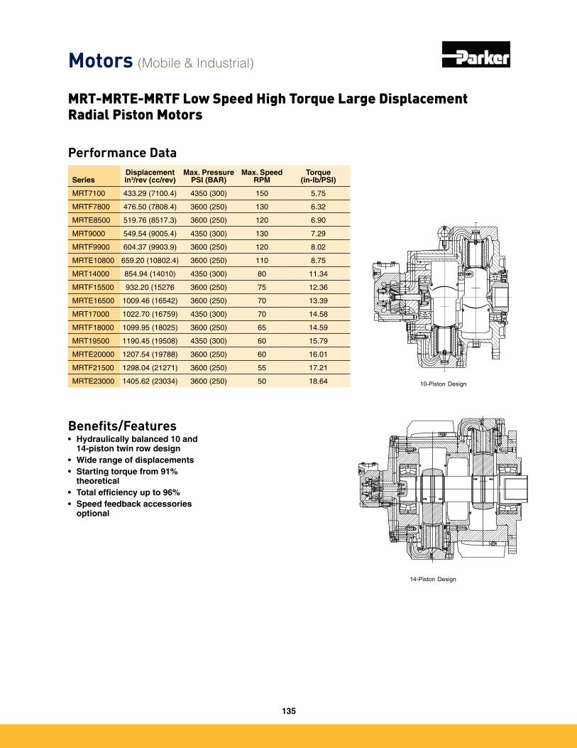
Performance Data
SeriesDisplacementin3/rev (cc/rev)
Max. PressurePSI (BAR)
Max. SpeedRPM
Torque (in-lb/PSI)
MRT7100 433�29 (7100�4) 4350 (300) 150 5�75
MRTF7800 476�50 (7808�4) 3600 (250) 130 6�32
MRTE8500 519�76 (8517�3) 3600 (250) 120 6�90
MRT9000 549�54 (9005�4) 4350 (300) 130 7�29
MRTF9900 604�37 (9903�9) 3600 (250) 120 8�02
MRTE10800 659�20 (10802�4) 3600 (250) 110 8�75
MRT14000 854�94 (14010) 4350 (300) 80 11�34
MRTF15500 932�20 (15276 3600 (250) 75 12�36
MRTE16500 1009�46 (16542) 3600 (250) 70 13�39
MRT17000 1022�70 (16759) 4350 (300) 70 14�58
MRTF18000 1099�95 (18025) 3600 (250) 65 14�59
MRT19500 1190�45 (19508) 4350 (300) 60 15�79
MRTE20000 1207�54 (19788) 3600 (250) 60 16�01
MRTF21500 1298�04 (21271) 3600 (250) 55 17�21
MRTE23000 1405�62 (23034) 3600 (250) 50 18�64 10-Piston Design
14-Piston Design
Benefits/Features• Hydraulically balanced 10 and
14-piston twin row design• Wide range of displacements• Starting torque from 91%
theoretical• Total efficiency up to 96%• Speed feedback accessories
optional
Motors (Mobile & Industrial)
MRT-MRTE-MRTF Low Speed High Torque Large Displacement Radial Piston Motors
135
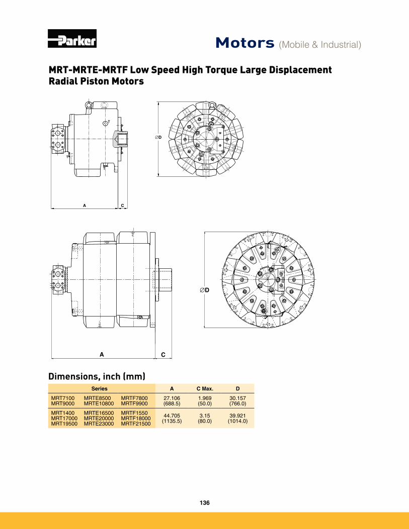
Series A C Max. D
MRT7100 MRT9000
MRTE8500 MRTE10800
MRTF7800 MRTF9900
27�106 (688�5)
1�969 (50�0)
30�157 (766�0)
MRT1400 MRT17000 MRT19500
MRTE16500 MRTE20000 MRTE23000
MRTF1550 MRTF18000 MRTF21500
44�705 (1135�5)
3�15(80�0)
39�921 (1014�0)
Dimensions, inch (mm)
Motors (Mobile & Industrial)
MRT-MRTE-MRTF Low Speed High Torque Large Displacement Radial Piston Motors
136
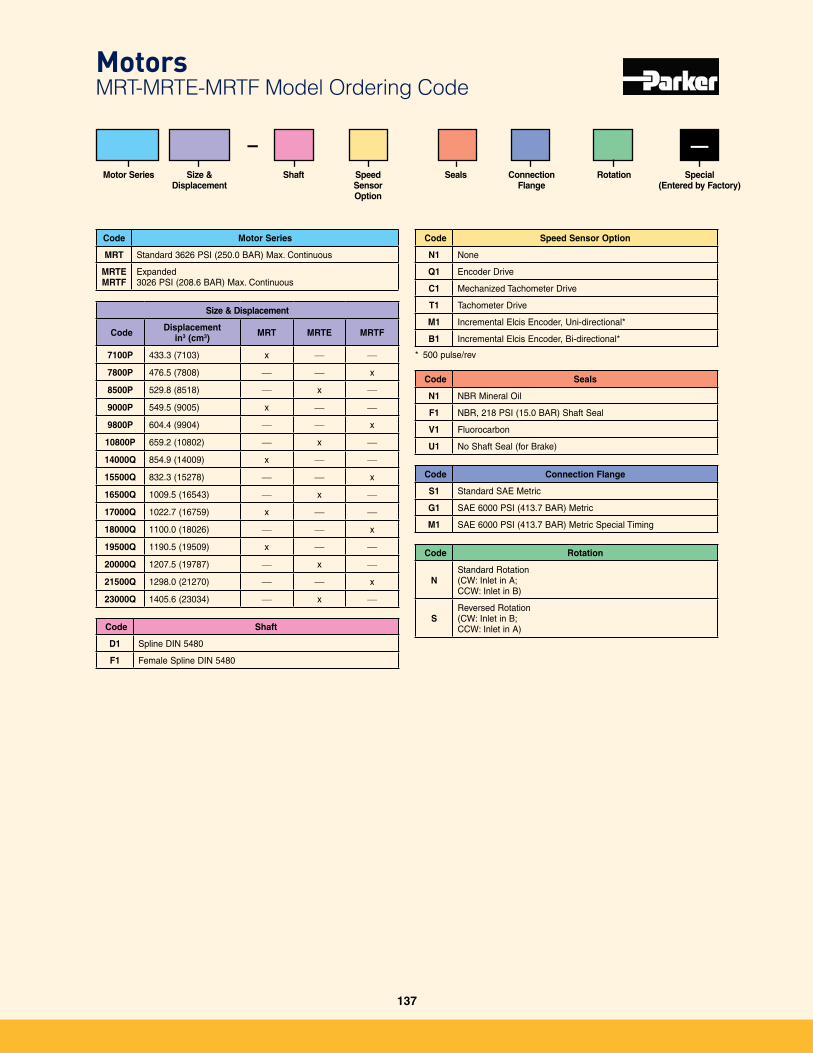
Code Motor Series
MRT Standard 3626 PSI (250�0 BAR) Max� Continuous
MRTEMRTF
Expanded 3026 PSI (208�6 BAR) Max� Continuous
Size & Displacement
Motor Series Connection Flange
SealsShaft
–Speed Sensor Option
Code Rotation
N Standard Rotation(CW: Inlet in A; CCW: Inlet in B)
SReversed Rotation(CW: Inlet in B; CCW: Inlet in A)
—
Code Connection Flange
S1 Standard SAE Metric
G1 SAE 6000 PSI (413�7 BAR) Metric
M1 SAE 6000 PSI (413�7 BAR) Metric Special Timing
Code Seals
N1 NBR Mineral Oil
F1 NBR, 218 PSI (15�0 BAR) Shaft Seal
V1 Fluorocarbon
U1 No Shaft Seal (for Brake)
Size & Displacement
Code Displacement in3 (cm3) MRT MRTE MRTF
7100P 433�3 (7103) x — —
7800P 476�5 (7808) — — x
8500P 529�8 (8518) — x —
9000P 549�5 (9005) x — —
9800P 604�4 (9904) — — x
10800P 659�2 (10802) — x —
14000Q 854�9 (14009) x — —
15500Q 832�3 (15278) — — x
16500Q 1009�5 (16543) — x —
17000Q 1022�7 (16759) x — —
18000Q 1100�0 (18026) — — x
19500Q 1190�5 (19509) x — —
20000Q 1207�5 (19787) — x —
21500Q 1298�0 (21270) — — x
23000Q 1405�6 (23034) — x —
Code Speed Sensor Option
N1 None
Q1 Encoder Drive
C1 Mechanized Tachometer Drive
T1 Tachometer Drive
M1 Incremental Elcis Encoder, Uni-directional*
B1 Incremental Elcis Encoder, Bi-directional*
* 500 pulse/rev
Code Shaft
D1 Spline DIN 5480
F1 Female Spline DIN 5480
Motors MRT-MRTE-MRTF Model Ordering Code
Rotation Special(Entered by Factory)
137
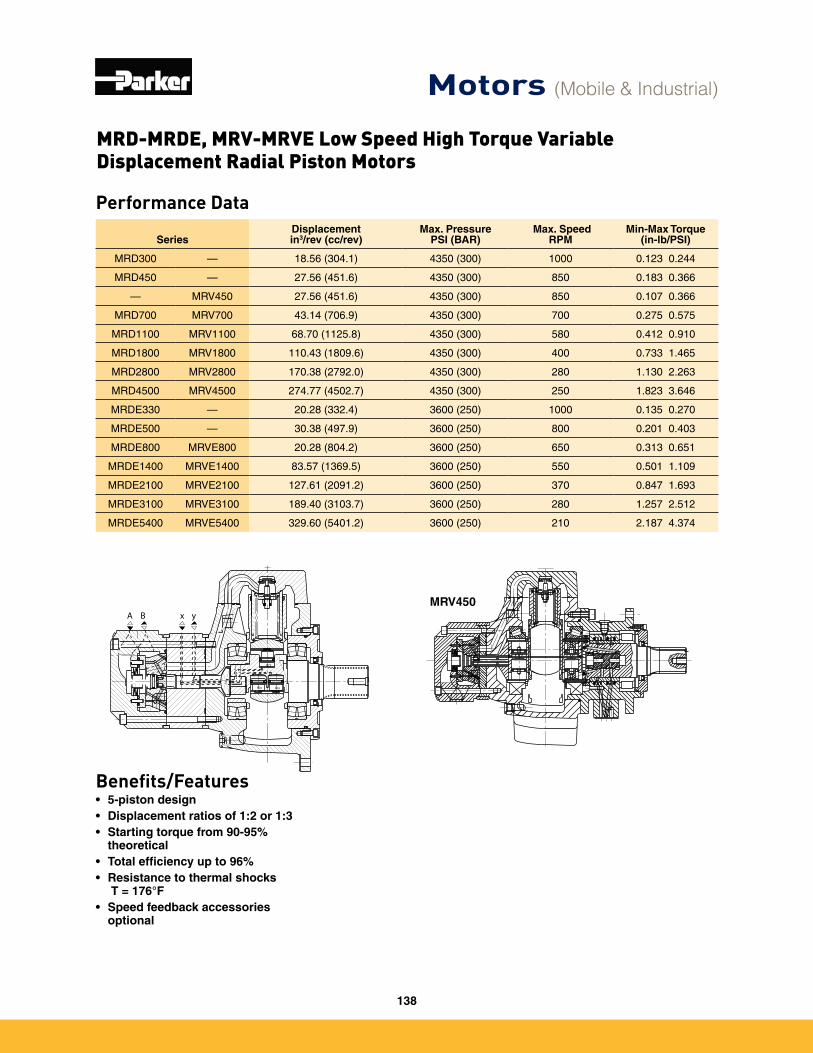
Performance Data
SeriesDisplacementin3/rev (cc/rev)
Max. PressurePSI (BAR)
Max. SpeedRPM
Min-Max Torque (in-lb/PSI)
MRD300 — 18�56 (304�1) 4350 (300) 1000 0�123 0�244
MRD450 — 27�56 (451�6) 4350 (300) 850 0�183 0�366
— MRV450 27�56 (451�6) 4350 (300) 850 0�107 0�366
MRD700 MRV700 43�14 (706�9) 4350 (300) 700 0�275 0�575
MRD1100 MRV1100 68�70 (1125�8) 4350 (300) 580 0�412 0�910
MRD1800 MRV1800 110�43 (1809�6) 4350 (300) 400 0�733 1�465
MRD2800 MRV2800 170�38 (2792�0) 4350 (300) 280 1�130 2�263
MRD4500 MRV4500 274�77 (4502�7) 4350 (300) 250 1�823 3�646
MRDE330 — 20�28 (332�4) 3600 (250) 1000 0�135 0�270
MRDE500 — 30�38 (497�9) 3600 (250) 800 0�201 0�403
MRDE800 MRVE800 20�28 (804�2) 3600 (250) 650 0�313 0�651
MRDE1400 MRVE1400 83�57 (1369�5) 3600 (250) 550 0�501 1�109
MRDE2100 MRVE2100 127�61 (2091�2) 3600 (250) 370 0�847 1�693
MRDE3100 MRVE3100 189�40 (3103�7) 3600 (250) 280 1�257 2�512
MRDE5400 MRVE5400 329�60 (5401�2) 3600 (250) 210 2�187 4�374
Benefits/Features• 5-piston design• Displacement ratios of 1:2 or 1:3• Starting torque from 90-95%
theoretical• Total efficiency up to 96%• Resistance to thermal shocks
ΔT = 176°F• Speed feedback accessories
optional
MRV450
Motors (Mobile & Industrial)
MRD-MRDE, MRV-MRVE Low Speed High Torque Variable Displacement Radial Piston Motors
138
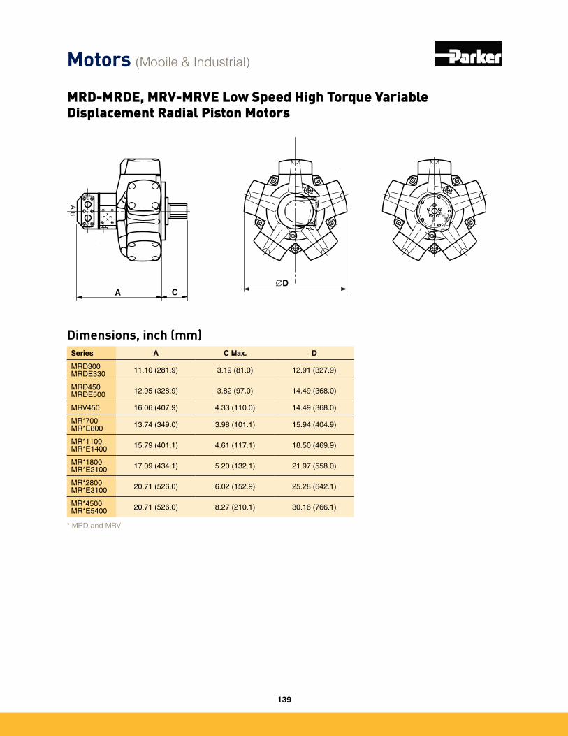
Motors (Mobile & Industrial)
MRD-MRDE, MRV-MRVE Low Speed High Torque Variable Displacement Radial Piston Motors
* MRD and MRV
Dimensions, inch (mm)Series A C Max. D
MRD300 MRDE330 11�10 (281�9) 3�19 (81�0) 12�91 (327�9)
MRD450 MRDE500 12�95 (328�9) 3�82 (97�0) 14�49 (368�0)
MRV450 16�06 (407�9) 4�33 (110�0) 14�49 (368�0)
MR*700 MR*E800 13�74 (349�0) 3�98 (101�1) 15�94 (404�9)
MR*1100 MR*E1400 15�79 (401�1) 4�61 (117�1) 18�50 (469�9)
MR*1800 MR*E2100 17�09 (434�1) 5�20 (132�1) 21�97 (558�0)
MR*2800 MR*E3100 20�71 (526�0) 6�02 (152�9) 25�28 (642�1)
MR*4500 MR*E5400 20�71 (526�0) 8�27 (210�1) 30�16 (766�1)
139
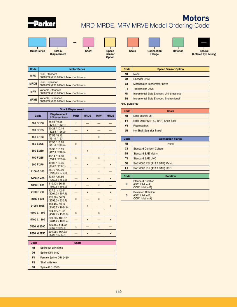
Code Motor Series
MRD Dual, Standard 3626 PSI (250�0 BAR) Max� Continuous
MRDE Dual, Expanded 3026 PSI (208�6 BAR) Max� Continuous
MRV Variable, Standard 3626 PSI (250�0 BAR) Max� Continuous
MRVE Variable, Expanded 3026 PSI (208�6 BAR) Max� Continuous
Connection Flange
SealsShaft Speed Sensor Option
Code Rotation
N Standard Rotation(CW: Inlet in A; CCW: Inlet in B)
SReversed Rotation(CW: Inlet in B; CCW: Inlet in A)
Code Connection Flange
N1 None
C1 Standard Denison Calzoni
S1 Standard SAE Metric
T1 Standard SAE UNC
G1 SAE 6000 PSI (413�7 BAR) Metric
L1 SAE 6000 PSI (413�7 BAR) UNC
Code Seals
N1 NBR Mineral Oil
F1 NBR, 218 PSI (15�0 BAR) Shaft Seal
V1 Fluorocarbon
U1 No Shaft Seal (for Brake)
Size & Displacement
Code Displacement in3/rev (cc/rev) MRD MRDE MRV MRVE
300 D 150 18�56 / 9�28(304�1 / 152�1) x — — —
330 D 165 20�28 / 10�14(332�4 / 166�2) — x — —
450 E 133 27�56 / 8�12(451�6 / 133) — — x —
450 E 225 27�56 / 13�78(451�6 / 225�8) x — — —
500 E 250 30�38 / 15�19(497�9 / 248�9) — x — —
700 F 235 43�14 / 14�38(706�9 / 235�6) x — x —
800 F 270 49�08 / 16�36(804�2 / 268�1) — x — x
1100 G 375 68�70 / 22�90(1125�8 / 375�3) x x —
1400 G 450 83�57 / 27�86(1369�5 / 456�5) — x — x
1800 H 600 110�43 / 36�81(1809�6 / 603�2) x — x —
2100 H 700 127�61 / 42�54(2091�2 / 697�1) — x — x
2800 I 930 170�38 / 56�79(2792�0 / 930�7) x — x —
3100 I 1035 189�40 / 63�14(3103�7 / 1034�6) — x — x
4500 L 1500 274�77 / 91�59(4502�7 / 1500�9) x — x —
5400 L 1800 329�60 / 109�87(5401�2 / 1800�4) — x — x
7000 M 2300 425�15 / 141�72(6967 / 2322�4) x — x —
8200 M 2750 501�98 / 167�33(8226 / 2742�1) — x — x
Code Speed Sensor Option
N1 None
Q1 Encoder Drive
C1 Mechanized Tachometer Drive
T1 Tachometer Drive
M1 Incremental Elcis Encoder, Uni-directional*
B1 Incremental Elcis Encoder, Bi-directional*
*500 pulse/rev
Code Shaft
N1 Spline Ex DIN 5463
D1 Spline DIN 5480
F1 Female Spline DIN 5480
P1 Shaft with Key
B1 Spline B�S� 3550
MotorsMRD-MRDE, MRV-MRVE Model Ordering Code
Rotation
Size &
DisplacementMotor Series
–Special
(Entered by Factory)
—
140

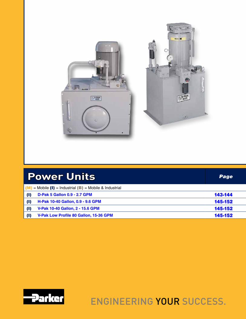
Power Units Page
(M) = Mobile (I) = Industrial (B) = Mobile & Industrial
(I) D-Pak 5 Gallon 0.9 - 2.7 GPM 143-144(I) H-Pak 10-40 Gallon, 0.9 - 9.6 GPM 145-152(I) V-Pak 10-40 Gallon, 2 - 15.6 GPM 145-152(I) V-Pak Low Profile 80 Gallon, 15-36 GPM 145-152
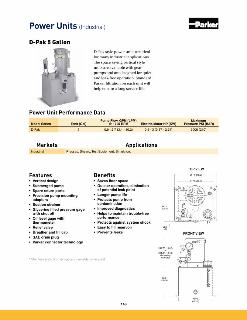
Power Units (Industrial)
D-Pak style power units are ideal for many industrial applications. The space saving vertical style units are available with gear pumps and are designed for quiet and leak-free operation. Standard Parker filtration on each unit will help ensure a long service life.
Power Unit Performance Data
Model Series Tank (Gal)Pump Flow, GPM (LPM)
@ 1725 RPM Electric Motor HP (KW)Maximum
Pressure PSI (BAR)
D-Pak 5 0�9 - 2�7 (3�4 - 10�2) 0�5 - 3 (0�37 - 2�24) 3000 (210)
D-Pak 5 Gallon
263.1(10.36)
317.5 (12.5)
381.0 (15.0)
317.5 (12.5)
307.9(12.12)
22.9(.9)
P
T
B A
TOP VIEW
FRONT VIEW
269.75 (10.62)to
341.37 (13.44)dependingon motor
Features• Vertical design• Submerged pump• Spare return ports• Precision pump mounting
adapters• Suction strainer• Glycerine filled pressure gage
with shut off• Oil level gage with
thermometer• Relief valve• Breather and fill cap• SAE drain plug• Parker connector technology
Benefits• Saves floor space• Quieter operation, elimination
of potential leak point• Longer pump life• Protects pump from
contamination• Improved diagnostics• Helps to maintain trouble-free
performance• Protects against system shock• Easy to fill reservoir• Prevents leaks
Markets ApplicationsIndustrial Presses, Shears, Test Equipment, Simulators
* Stainless units & other options available on request
143
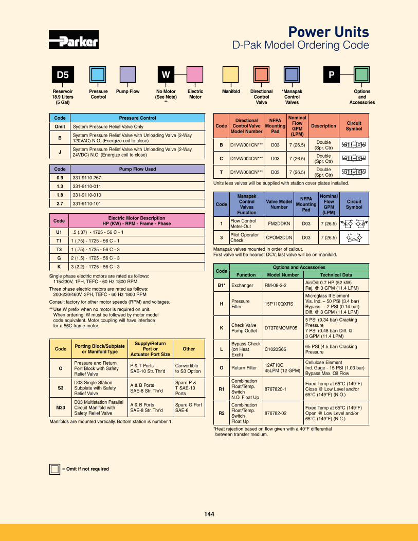
Code Electric Motor DescriptionHP (KW) - RPM - Frame - Phase
U1 �5 (�37) - 1725 - 56 C - 1
T1 1 (�75) - 1725 - 56 C - 1
T3 1 (�75) - 1725 - 56 C - 3
G 2 (1�5) - 1725 - 56 C - 3
K 3 (2�2) - 1725 - 56 C - 3
Single phase electric motors are rated as follows: 115/230V, 1PH, TEFC - 60 Hz 1800 RPM
Three phase electric motors are rated as follows: 200-230/460V, 3PH, TEFC - 60 Hz 1800 RPM
Consult factory for other motor speeds (RPM) and voltages�
** Use W prefix when no motor is required on unit� When ordering, W must be followed by motor model code equivalent� Motor coupling will have interface for a 56C frame motor�
WD5
Code Pump Flow Used
0.9 331-9110-267
1.3 331-9110-011
1.8 331-9110-010
2.7 331-9110-101
P
Reservoir18.9 Liters
(5 Gal)
No Motor (See Note)
**
Code Pressure Control
Omit System Pressure Relief Valve Only
B System Pressure Relief Valve with Unloading Valve (2-Way 120VAC) N�O� (Energize coil to close)
J System Pressure Relief Valve with Unloading Valve (2-Way 24VDC) N�O� (Energize coil to close)
Code Porting Block/Subplate or Manifold Type
Supply/Return Port or
Actuator Port SizeOther
OPressure and Return Port Block with Safety Relief Valve
P & T PortsSAE-10 Str� Thr'd
Convertible to S3 Option
S3D03 Single Station Subplate with Safety Relief Valve
A & B PortsSAE-8 Str� Thr'd
Spare P & T SAE-10 Ports
M33D03 Multistation Parallel Circuit Manifold with Safety Relief Valve
A & B PortsSAE-8 Str� Thr'd
Spare G Port SAE-6
Manifolds are mounted vertically� Bottom station is number 1�
Code
ManapakControlValves
Function
Valve Model Number
NFPA Mounting
Pad
Nominal Flow GPM (LPM)
Circuit Symbol
1 Flow Control Meter-Out FM2DDKN D03 7 (26�5)
A B
3 Pilot Operator Check CPOM2DDN D03 7 (26�5)
A B
Manapak valves mounted in order of callout� First valve will be nearest DCV; last valve will be on manifold�
CodeOptions and Accessories
Function Model Number Technical Data
B1* Exchanger RM-08-2-2 Air/Oil: 0�7 HP (52 kW) Rej� @ 3 GPM (11�4 LPM)
H Pressure Filter 15P110QXRS
Microglass II ElementVis� Ind� – 50 PSI (3�4 bar)Bypass – 2 PSI (0�14 bar)Diff� @ 3 GPM (11�4 LPM)
K Check ValvePump Outlet DT370MOMF05
5 PSI (0�34 bar) Cracking Pressure7 PSI (0�48 bar) Diff� @ 3 GPM (11�4 LPM)
LBypass Check(on Heat Exch)
C1020S65 65 PSI (4�5 bar) Cracking Pressure
O Return Filter 12AT10C 45LPM (12 GPM)
Cellulose ElementInd� Gage - 15 PSI (1�03 bar)Bypass Max� Oil Flow
R1
CombinationFloat/Temp� SwitchN�O� Float Up
8767820-1Fixed Temp at 65°C (149°F)Close @ Low Level and/or65°C (149°F) (N�O�)
R2
Combination Float/Temp� SwitchFloat Up
876782-02Fixed Temp at 65°C (149°F)Open @ Low Level and/or65°C (149°F) (N�C�)
*Heat rejection based on flow given with a 40°F differential between transfer medium�
CodeDirectional
Control Valve Model Number
NFPA Mounting
Pad
Nominal Flow GPM (LPM)
Description Circuit Symbol
B D1VW001CN*** D03 7 (26�5) Double (Spr� Ctr)
A B
P T
➤➤➤
➤
C D1VW004CN*** D03 7 (26�5) Double (Spr� Ctr)
A B
P T
➤➤➤
➤
T D1VW008CN*** D03 7 (26�5) Double (Spr� Ctr)
A B
P T
➤➤➤
➤
Units less valves will be supplied with station cover plates installed�
= Omit if not required
Pressure Control
Pump Flow ElectricMotor
Manifold DirectionalControl Valve
*ManapakControlValves
Optionsand
Accessories
Power Units D-Pak Model Ordering Code
144
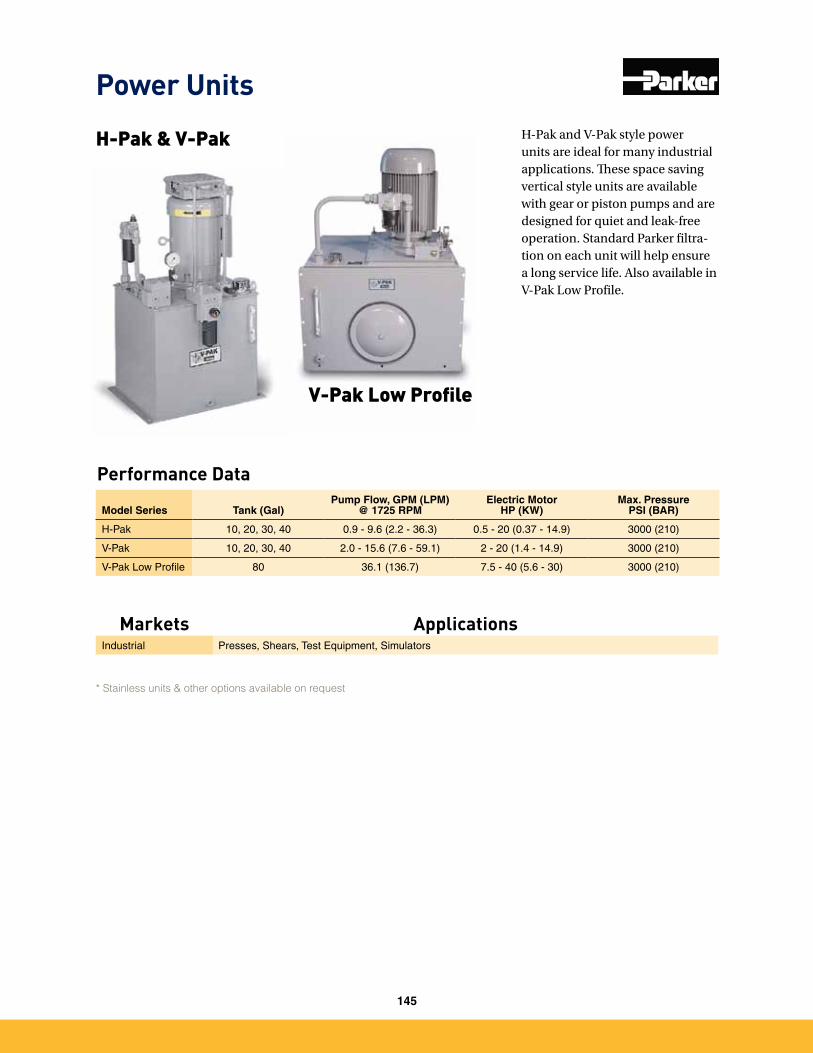
H-Pak and V-Pak style power units are ideal for many industrial applications. These space saving vertical style units are available with gear or piston pumps and are designed for quiet and leak-free operation. Standard Parker filtra-tion on each unit will help ensure a long service life. Also available in V-Pak Low Profile.
Performance Data
Model Series Tank (Gal)Pump Flow, GPM (LPM)
@ 1725 RPMElectric Motor
HP (KW)Max. Pressure
PSI (BAR)
H-Pak 10, 20, 30, 40 0�9 - 9�6 (2�2 - 36�3) 0�5 - 20 (0�37 - 14�9) 3000 (210)
V-Pak 10, 20, 30, 40 2�0 - 15�6 (7�6 - 59�1) 2 - 20 (1�4 - 14�9) 3000 (210)
V-Pak Low Profile 80 36�1 (136�7) 7�5 - 40 (5�6 - 30) 3000 (210)
H-Pak & V-Pak
V-Pak Low Profile
Power Units
Markets ApplicationsIndustrial Presses, Shears, Test Equipment, Simulators
* Stainless units & other options available on request
145
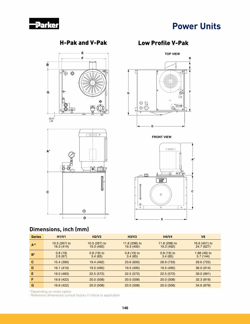
Power Units
22.9(.9)
G
B
E
F
D
A
C
A-D03B-D05
B-D03A-D05
PT
PU
MP
PR
IME
CO
NT
RO
LP
UM
P C
OM
PE
NS
AT
OR
DO NOT ADJUSTSAFETY RELIEF
T
P
D
F
B
E
V-PAK
A
C
G
TOP VIEW
FRONT VIEW
Series H1/V1 H2/V2 H3/V3 H4/V4 V8
A*† 10�5 (267) to 16�3 (414)
10�5 (267) to 19�3 (492)
11�8 (298) to 19�3 (492)
11�8 (298) to 19�3 (492)
16�6 (451) to 24�7 (627)
B* 0�8 (19)2�6 (67)
0�8 (19) to 3�4 (85)
0�8 (19) to 3�4 (85)
0�8 (19) to 3�4 (85)
1�88 (48) to 5�7 (144)
C 15�4 (390) 19�4 (492) 23�6 (600) 28�9 (733) 28�6 (725)
D 16�1 (410) 19�5 (495) 19�5 (495) 19�5 (495) 36�0 (914)
E 19�0 (483) 22�5 (572) 22�5 (572) 22�5 (572) 39�0 (991)
F 16�6 (422) 20�0 (508) 20�0 (508) 20�0 (508) 32�3 (819)
G 16�6 (422) 20�0 (508) 20�0 (508) 20�0 (508) 34�6 (879)
* Depending on motor option† Reference dimensions consult factory if critical to application
H-Pak and V-Pak Low Profile V-Pak
Dimensions, inch (mm)
*
*
146
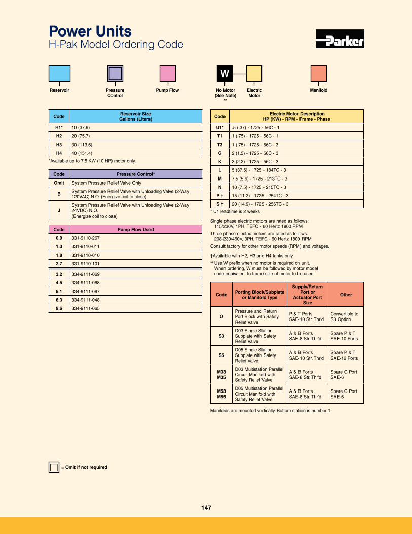
Power Units H-Pak Model Ordering Code
Code Electric Motor DescriptionHP (KW) - RPM - Frame - Phase
U1* �5 (�37) - 1725 - 56C - 1
T1 1 (�75) - 1725 - 56C - 1
T3 1 (�75) - 1725 - 56C - 3
G 2 (1�5) - 1725 - 56C - 3
K 3 (2�2) - 1725 - 56C - 3
L 5 (37�5) - 1725 - 184TC - 3
M 7�5 (5�6) - 1725 - 213TC - 3
N 10 (7�5) - 1725 - 215TC - 3
P † 15 (11�2) - 1725 - 254TC - 3
S † 20 (14�9) - 1725 - 256TC - 3
* U1 leadtime is 2 weeks
Single phase electric motors are rated as follows: 115/230V, 1PH, TEFC - 60 Hertz 1800 RPM
Three phase electric motors are rated as follows: 208-230/460V, 3PH, TEFC - 60 Hertz 1800 RPM
Consult factory for other motor speeds (RPM) and voltages�
†Available with H2, H3 and H4 tanks only�
** Use W prefix when no motor is required on unit� When ordering, W must be followed by motor model code equivalent to frame size of motor to be used�
W
Code Pump Flow Used
0.9 331-9110-267
1.3 331-9110-011
1.8 331-9110-010
2.7 331-9110-101
3.2 334-9111-069
4.5 334-9111-068
5.1 334-9111-067
6.3 334-9111-048
9.6 334-9111-065
Code Reservoir SizeGallons (Liters)
H1* 10 (37�9)
H2 20 (75�7)
H3 30 (113�6)
H4 40 (151�4)
Reservoir No Motor (See Note)
**
Code Pressure Control*
Omit System Pressure Relief Valve Only
B System Pressure Relief Valve with Unloading Valve (2-Way 120VAC) N�O� (Energize coil to close)
JSystem Pressure Relief Valve with Unloading Valve (2-Way 24VDC) N�O�(Energize coil to close)
Code Porting Block/Subplate or Manifold Type
Supply/Return Port or
Actuator Port Size
Other
OPressure and Return Port Block with Safety Relief Valve
P & T PortsSAE-10 Str� Thr'd
Convertible to S3 Option
S3D03 Single Station Subplate with Safety Relief Valve
A & B PortsSAE-8 Str� Thr'd
Spare P & T SAE-10 Ports
S5D05 Single Station Subplate with Safety Relief Valve
A & B PortsSAE-10 Str� Thr'd
Spare P & T SAE-12 Ports
M33M35
D03 Multistation Parallel Circuit Manifold with Safety Relief Valve
A & B PortsSAE-8 Str� Thr'd
Spare G Port SAE-6
M53M55
D05 Multistation Parallel Circuit Manifold with Safety Relief Valve
A & B PortsSAE-8 Str� Thr'd
Spare G Port SAE-6
Manifolds are mounted vertically� Bottom station is number 1�
Pressure Control
Pump Flow ElectricMotor
Manifold
*Available up to 7�5 KW (10 HP) motor only�
= Omit if not required
147
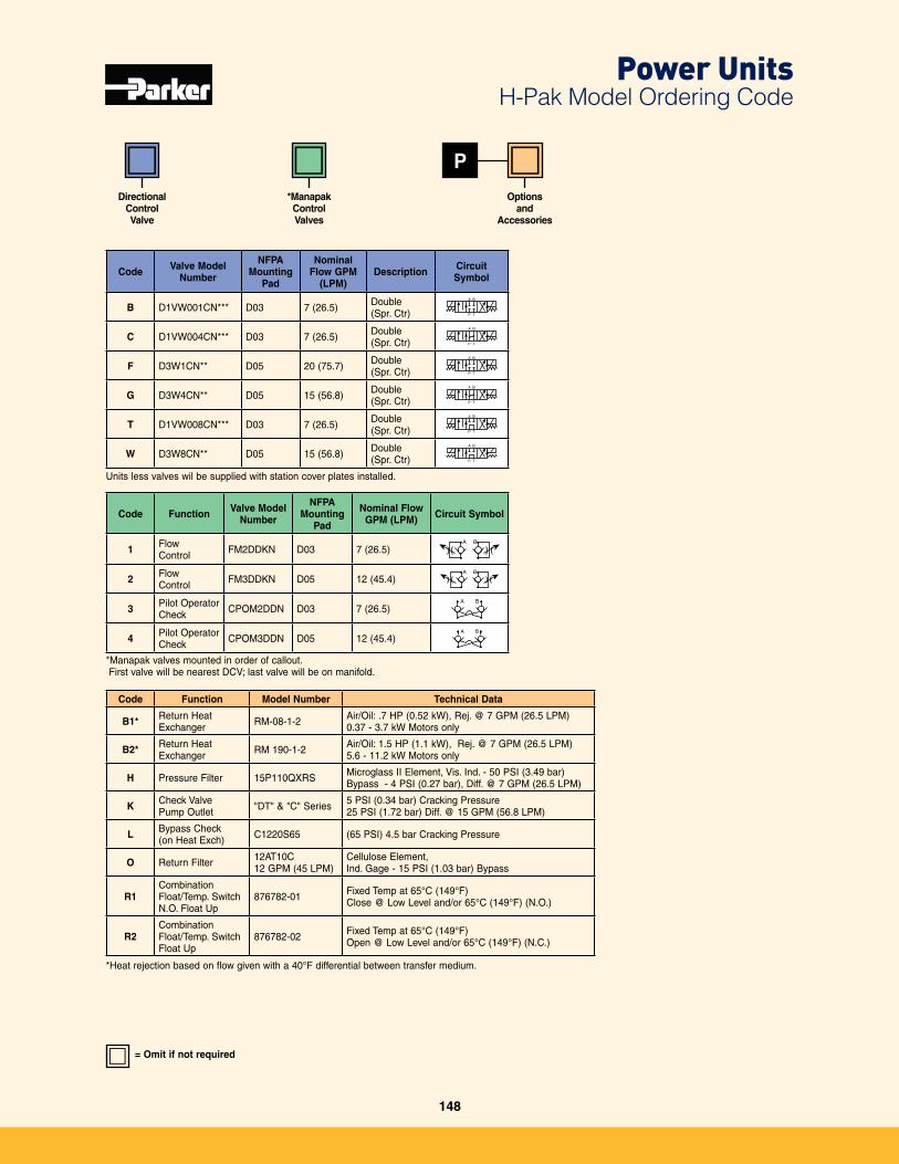
Power Units H-Pak Model Ordering Code
P
Code Function Valve Model Number
NFPA Mounting
Pad
Nominal Flow GPM (LPM) Circuit Symbol
1 Flow Control FM2DDKN D03 7 (26�5)
A B
2 Flow Control FM3DDKN D05 12 (45�4)
A B
3 Pilot Operator Check CPOM2DDN D03 7 (26�5)
A B
4 Pilot Operator Check CPOM3DDN D05 12 (45�4)
A B
*Manapak valves mounted in order of callout� First valve will be nearest DCV; last valve will be on manifold�
Code Function Model Number Technical Data
B1* Return Heat Exchanger RM-08-1-2 Air/Oil: �7 HP (0�52 kW), Rej� @ 7 GPM (26�5 LPM)
0�37 - 3�7 kW Motors only
B2* Return Heat Exchanger RM 190-1-2 Air/Oil: 1�5 HP (1�1 kW), Rej� @ 7 GPM (26�5 LPM)
5�6 - 11�2 kW Motors only
H Pressure Filter 15P110QXRS Microglass II Element, Vis� Ind� - 50 PSI (3�49 bar)Bypass - 4 PSI (0�27 bar), Diff� @ 7 GPM (26�5 LPM)
K Check ValvePump Outlet "DT" & "C" Series 5 PSI (0�34 bar) Cracking Pressure
25 PSI (1�72 bar) Diff� @ 15 GPM (56�8 LPM)
L Bypass Check(on Heat Exch) C1220S65 (65 PSI) 4�5 bar Cracking Pressure
O Return Filter 12AT10C 12 GPM (45 LPM)
Cellulose Element, Ind� Gage - 15 PSI (1�03 bar) Bypass
R1CombinationFloat/Temp� SwitchN�O� Float Up
876782-01 Fixed Temp at 65°C (149°F)Close @ Low Level and/or 65°C (149°F) (N�O�)
R2Combination Float/Temp� SwitchFloat Up
876782-02 Fixed Temp at 65°C (149°F)Open @ Low Level and/or 65°C (149°F) (N�C�)
*Heat rejection based on flow given with a 40°F differential between transfer medium�
Code Valve Model Number
NFPA Mounting
Pad
Nominal Flow GPM
(LPM)Description Circuit
Symbol
B D1VW001CN*** D03 7 (26�5) Double (Spr� Ctr)
A B
P T
➤➤➤
➤
C D1VW004CN*** D03 7 (26�5) Double (Spr� Ctr)
A B
P T
➤➤➤
➤
F D3W1CN** D05 20 (75�7) Double (Spr� Ctr)
A B
P T
➤➤➤
➤
G D3W4CN** D05 15 (56�8) Double (Spr� Ctr)
A B
P T
➤➤➤
➤
T D1VW008CN*** D03 7 (26�5) Double (Spr� Ctr)
A B
P T
➤➤➤
➤
W D3W8CN** D05 15 (56�8) Double (Spr� Ctr)
A B
P T
➤➤➤
➤
Units less valves wil be supplied with station cover plates installed�
DirectionalControl Valve
*ManapakControlValves
Optionsand
Accessories
= Omit if not required
148
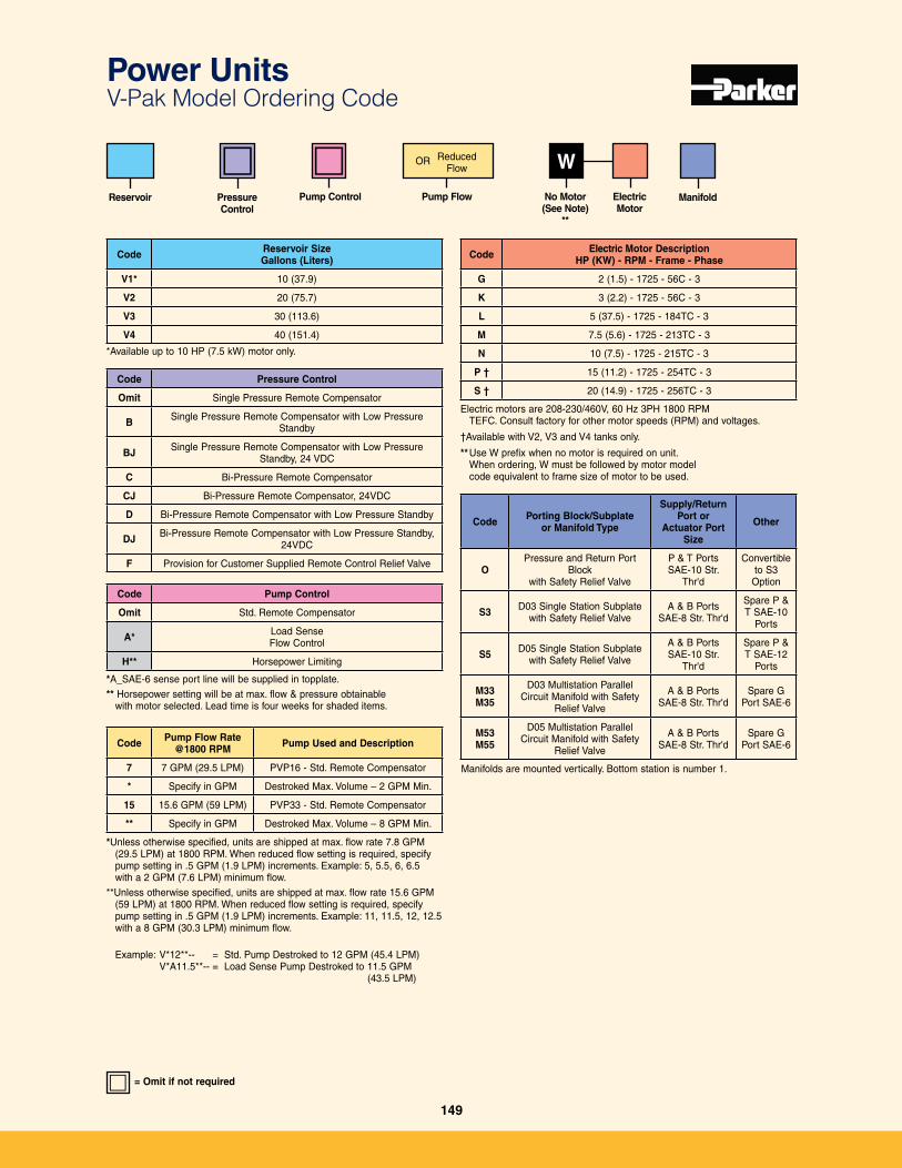
Code Electric Motor DescriptionHP (KW) - RPM - Frame - Phase
G 2 (1�5) - 1725 - 56C - 3
K 3 (2�2) - 1725 - 56C - 3
L 5 (37�5) - 1725 - 184TC - 3
M 7�5 (5�6) - 1725 - 213TC - 3
N 10 (7�5) - 1725 - 215TC - 3
P † 15 (11�2) - 1725 - 254TC - 3
S † 20 (14�9) - 1725 - 256TC - 3
Electric motors are 208-230/460V, 60 Hz 3PH 1800 RPM TEFC� Consult factory for other motor speeds (RPM) and voltages�
†Available with V2, V3 and V4 tanks only�
** Use W prefix when no motor is required on unit� When ordering, W must be followed by motor model code equivalent to frame size of motor to be used�
W
Code Reservoir SizeGallons (Liters)
V1* 10 (37�9)
V2 20 (75�7)
V3 30 (113�6)
V4 40 (151�4)
No Motor (See Note)
**
Code Pressure Control
Omit Single Pressure Remote Compensator
B Single Pressure Remote Compensator with Low Pressure Standby
BJ Single Pressure Remote Compensator with Low Pressure Standby, 24 VDC
C Bi-Pressure Remote Compensator
CJ Bi-Pressure Remote Compensator, 24VDC
D Bi-Pressure Remote Compensator with Low Pressure Standby
DJ Bi-Pressure Remote Compensator with Low Pressure Standby, 24VDC
F Provision for Customer Supplied Remote Control Relief Valve
Code Porting Block/Subplate or Manifold Type
Supply/Return Port or
Actuator Port Size
Other
OPressure and Return Port
Block with Safety Relief Valve
P & T PortsSAE-10 Str�
Thr'd
Convertible to S3
Option
S3 D03 Single Station Subplate with Safety Relief Valve
A & B PortsSAE-8 Str� Thr'd
Spare P & T SAE-10
Ports
S5 D05 Single Station Subplate with Safety Relief Valve
A & B PortsSAE-10 Str�
Thr'd
Spare P & T SAE-12
Ports
M33M35
D03 Multistation Parallel Circuit Manifold with Safety
Relief Valve
A & B PortsSAE-8 Str� Thr'd
Spare G Port SAE-6
M53M55
D05 Multistation Parallel Circuit Manifold with Safety
Relief Valve
A & B PortsSAE-8 Str� Thr'd
Spare G Port SAE-6
Manifolds are mounted vertically� Bottom station is number 1�
Pressure Control
Pump Control ElectricMotor
Manifold
*Available up to 10 HP (7�5 kW) motor only�
*A_SAE-6 sense port line will be supplied in topplate�
** Horsepower setting will be at max� flow & pressure obtainablewith motor selected� Lead time is four weeks for shaded items�
Code Pump Control
Omit Std� Remote Compensator
A* Load Sense Flow Control
H** Horsepower Limiting
Pump Flow
Reduced Flow
OR
Code Pump Flow Rate @1800 RPM Pump Used and Description
7 7 GPM (29�5 LPM) PVP16 - Std� Remote Compensator
* Specify in GPM Destroked Max� Volume – 2 GPM Min�
15 15�6 GPM (59 LPM) PVP33 - Std� Remote Compensator
** Specify in GPM Destroked Max� Volume – 8 GPM Min�
*Unless otherwise specified, units are shipped at max� flow rate 7�8 GPM (29�5 LPM) at 1800 RPM� When reduced flow setting is required, specify pump setting in �5 GPM (1�9 LPM) increments� Example: 5, 5�5, 6, 6�5 with a 2 GPM (7�6 LPM) minimum flow�
**Unless otherwise specified, units are shipped at max� flow rate 15�6 GPM (59 LPM) at 1800 RPM� When reduced flow setting is required, specify pump setting in �5 GPM (1�9 LPM) increments� Example: 11, 11�5, 12, 12�5 with a 8 GPM (30�3 LPM) minimum flow�
Example: V*12**-- = Std� Pump Destroked to 12 GPM (45�4 LPM) V*A11�5**-- = Load Sense Pump Destroked to 11�5 GPM
(43�5 LPM)
= Omit if not required
Power Units V-Pak Model Ordering Code
Reservoir
149
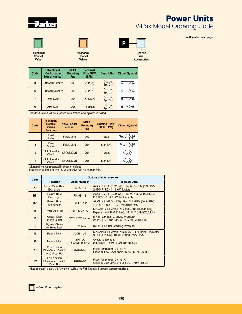
P
Code
Manapak ControlValves
Function
Valve Model Number
NFPA Mounting
Pad
Nominal Flow GPM (LPM) Circuit Symbol
1 Flow Control FM2DDKN D03 7 (26�5)
A B
2 Flow Control FM3DDKN D05 12 (45�4)
A B
3 Pilot Operator Check CPOM2DDN D03 7 (26�5)
A B
4 Pilot Operator Check CPOM3DDN D05 12 (45�4)
A B
*Manapak valves mounted in order of callout� First valve will be nearest DCV; last valve will be on manifold�
CodeOptions and Accessories
Function Model Number Technical Data
A* Pump Case Heat Exchanger RM-08-4-2 Air/Oil: 0�7 HP (0�52 kW), Rej� @ �5 GPM (1�9 LPM)
2-15 HP (1�5 - 11�2 kW) Motors
B1* Return Heat Exchanger RM-08-1-2 Air/Oil: 0�7 HP (0�52 kW), Rej� @ 7 GPM (26�5 LPM)
2-5 HP (1�5 - 3�7 kW) Motors only
B2* Return Heat Exchanger RM 190-1-2 Air/Oil: 1�5 HP (1�1 kW), Rej� @ 7 GPM (26�5 LPM)
7�5-15 HP (5�6 - 11�2 kW) Motors only
H Pressure Filter 15P110QXRS Microglass II Element, Vis� Ind� - 50 PSI (3�49 bar)Bypass - 4 PSI (0�27 bar), Diff� @ 7 GPM (26�5 LPM)
K Check ValvePump Outlet "DT" & "C" Series 5 PSI (0�34 bar) Cracking Pressure
25 PSI (1�72 bar) Diff� @ 15 GPM (56�8 LPM)
L Bypass Check(on Heat Exch) C1220S65 (65 PSI) 4�5 bar Cracking Pressure
N Return Filter 40CN110B Microglass II Element, Visual 25 PSI (1�72 bar) Indicator 3 PSI (0�21 bar) Diff� @ 7 GPM (26�5 LPM)
O Return Filter 12AT10C 12 GPM (45 LPM)
Cellulose Element, Ind� Gage - 15 PSI (1�03 bar) Bypass
R1Combination
Float/Temp� SwitchN�O� Float Up
876782-01 Fixed Temp at 65°C (149°F)Close @ Low Level and/or 65°C (149°F) (N�O�)
R2Combination
Float/Temp� SwitchFloat Up
876782-02 Fixed Temp at 65°C (149°F)Open @ Low Level and/or 65°C (149°F) (N�C�)
*Heat rejection based on flow given with a 40°F differential between transfer medium�
CodeDirectional
Control Valve Model Number
NFPA Mounting
Pad
Nominal Flow GPM
(LPM)Description Circuit Symbol
B D1VW001CN*** D03 7 (26�5) Double (Spr� Ctr)
A B
P T
➤➤➤
➤
C D1VW004CN*** D03 7 (26�5) Double (Spr� Ctr)
A B
P T
➤➤➤
➤
F D3W1CN** D05 20 (75�7) Double (Spr� Ctr)
A B
P T
➤➤➤
➤
G D3W4CN** D05 15 (56�8) Double (Spr� Ctr)
A B
P T
➤➤➤
➤
Units less valves wil be supplied with station cover plates installed�
DirectionalControl Valve
*ManapakControlValves
Optionsand
Accessories
= Omit if not required
continued on next page
Power Units V-Pak Model Ordering Code
150
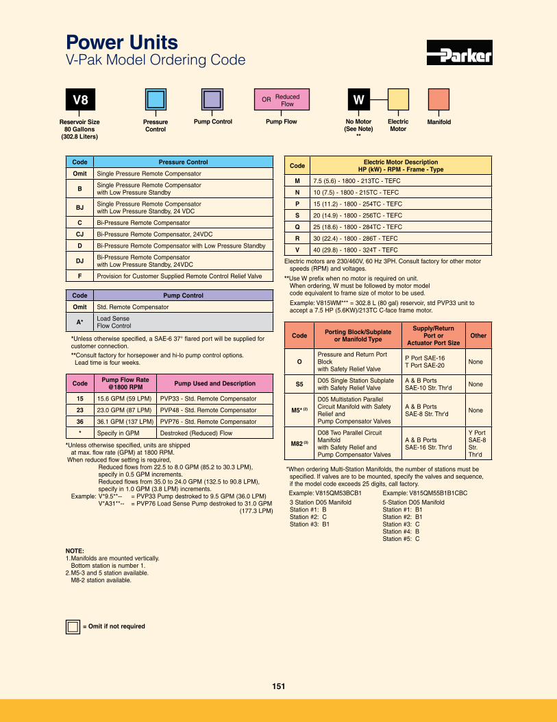
Code Electric Motor DescriptionHP (kW) - RPM - Frame - Type
M 7�5 (5�6) - 1800 - 213TC - TEFC
N 10 (7�5) - 1800 - 215TC - TEFC
P 15 (11�2) - 1800 - 254TC - TEFC
S 20 (14�9) - 1800 - 256TC - TEFC
Q 25 (18�6) - 1800 - 284TC - TEFC
R 30 (22�4) - 1800 - 286T - TEFC
V 40 (29�8) - 1800 - 324T - TEFC
Electric motors are 230/460V, 60 Hz 3PH� Consult factory for other motor speeds (RPM) and voltages�
**Use W prefix when no motor is required on unit� When ordering, W must be followed by motor model code equivalent to frame size of motor to be used�
Example: V815WM*** = 302�8 L (80 gal) reservoir, std PVP33 unit to accept a 7�5 HP (5�6KW)/213TC C-face frame motor�
WV8
Reservoir Size 80 Gallons
(302.8 Liters)
No Motor (See Note)
**
Code Pressure Control
Omit Single Pressure Remote Compensator
B Single Pressure Remote Compensator with Low Pressure Standby
BJ Single Pressure Remote Compensator with Low Pressure Standby, 24 VDC
C Bi-Pressure Remote Compensator
CJ Bi-Pressure Remote Compensator, 24VDC
D Bi-Pressure Remote Compensator with Low Pressure Standby
DJ Bi-Pressure Remote Compensator with Low Pressure Standby, 24VDC
F Provision for Customer Supplied Remote Control Relief Valve
Code Porting Block/Subplate or Manifold Type
Supply/Return Port or
Actuator Port SizeOther
OPressure and Return Port Block with Safety Relief Valve
P Port SAE-16T Port SAE-20 None
S5 D05 Single Station Subplate with Safety Relief Valve
A & B PortsSAE-10 Str� Thr'd None
M5* (2)
D05 Multistation Parallel Circuit Manifold with Safety Relief and Pump Compensator Valves
A & B PortsSAE-8 Str� Thr'd None
M82 (3)
D08 Two Parallel Circuit Manifold with Safety Relief and Pump Compensator Valves
A & B PortsSAE-16 Str� Thr'd
Y PortSAE-8 Str� Thr'd
*When ordering Multi-Station Manifolds, the number of stations must be specified� If valves are to be mounted, specify the valves and sequence, if the model code exceeds 25 digits, call factory�
Example: V815QM53BCB1 Example: V815QM55B1B1CBC
3 Station D05 Manifold 5-Station D05 Manifold Station #1: B Station #1: B1 Station #2: C Station #2: B1 Station #3: B1 Station #3: C Station #4: B Station #5: C
NOTE: 1� Manifolds are mounted vertically�
Bottom station is number 1�2� M5-3 and 5 station available�
M8-2 station available�
Pressure Control
Pump Control ElectricMotor
Manifold
Code Pump Control
Omit Std� Remote Compensator
A* Load Sense Flow Control
*Unless otherwise specified, a SAE-6 37° flared port will be supplied for customer connection�
**Consult factory for horsepower and hi-lo pump control options� Lead time is four weeks�
Pump Flow
Code Pump Flow Rate @1800 RPM Pump Used and Description
15 15�6 GPM (59 LPM) PVP33 - Std� Remote Compensator
23 23�0 GPM (87 LPM) PVP48 - Std� Remote Compensator
36 36�1 GPM (137 LPM) PVP76 - Std� Remote Compensator
* Specify in GPM Destroked (Reduced) Flow
*Unless otherwise specified, units are shipped at max� flow rate (GPM) at 1800 RPM�
When reduced flow setting is required, Reduced flows from 22�5 to 8�0 GPM (85�2 to 30�3 LPM),
specify in 0�5 GPM increments� Reduced flows from 35�0 to 24�0 GPM (132�5 to 90�8 LPM),
specify in 1�0 GPM (3�8 LPM) increments� Example: V*9�5**-- = PVP33 Pump destroked to 9�5 GPM (36�0 LPM)
V*A31**-- = PVP76 Load Sense Pump destroked to 31�0 GPM (177�3 LPM)
= Omit if not required
Reduced Flow
OR
Power Units V-Pak Model Ordering Code
151
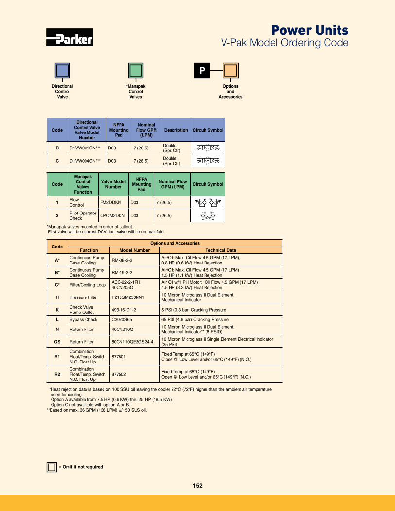
P
Code
ManapakControlValves
Function
Valve Model Number
NFPA Mounting
Pad
Nominal Flow GPM (LPM) Circuit Symbol
1 Flow Control FM2DDKN D03 7 (26�5)
A B
3 Pilot Operator Check CPOM2DDN D03 7 (26�5)
A B
*Manapak valves mounted in order of callout� First valve will be nearest DCV; last valve will be on manifold�
CodeOptions and Accessories
Function Model Number Technical Data
A* Continuous Pump Case Cooling RM-08-2-2 Air/Oil: Max� Oil Flow 4�5 GPM (17 LPM),
0�8 HP (0�6 kW) Heat Rejection
B* Continuous Pump Case Cooling RM-19-2-2 Air/Oil: Max� Oil Flow 4�5 GPM (17 LPM)
1�5 HP (1�1 kW) Heat Rejection
C* Filter/Cooling Loop ACC-22-2-1PH40CN205Q
Air Oil w/1 PH Motor: Oil Flow 4�5 GPM (17 LPM), 4�5 HP (3�3 kW) Heat Rejection
H Pressure Filter P210QM250NN1 10 Micron Microglass II Dual Element, Mechanical Indicator
K Check ValvePump Outlet 493-16-D1-2 5 PSI (0�3 bar) Cracking Pressure
L Bypass Check C2020S65 65 PSI (4�6 bar) Cracking Pressure
N Return Filter 40CN210Q 10 Micron Microglass II Dual Element, Mechanical Indicator** (8 PSID)
QS Return Filter 80CN110QE2GS24-4 10 Micron Microglass II Single Element Electrical Indicator (25 PSI)
R1CombinationFloat/Temp� SwitchN�O� Float Up
877501 Fixed Temp at 65°C (149°F)Close @ Low Level and/or 65°C (149°F) (N�O�)
R2Combination Float/Temp� SwitchN�C� Float Up
877502 Fixed Temp at 65°C (149°F)Open @ Low Level and/or 65°C (149°F) (N�C�)
*Heat rejection data is based on 100 SSU oil leaving the cooler 22°C (72°F) higher than the ambient air temperature used for cooling�
Option A available from 7�5 HP (0�6 KW) thru 25 HP (18�5 KW)� Option C not available with option A or B�**Based on max� 36 GPM (136 LPM) w/150 SUS oil�
Code
DirectionalControl Valve Valve Model
Number
NFPA Mounting
Pad
Nominal Flow GPM
(LPM)Description Circuit Symbol
B D1VW001CN*** D03 7 (26�5) Double (Spr� Ctr)
A B
P T
➤➤➤
➤
C D1VW004CN*** D03 7 (26�5) Double (Spr� Ctr)
A B
P T
➤➤➤
➤
DirectionalControl Valve
*ManapakControlValves
Optionsand
Accessories
= Omit if not required
Power Units V-Pak Model Ordering Code
152

Reference Page
(M) = Mobile (I) = Industrial (B) = Mobile & Industrial
SAE Flanges and Shafts 155 Formulas & Conversions 156 Offer of Sale 157
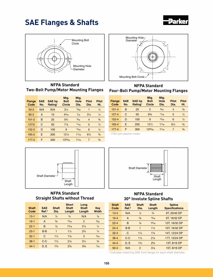
SAE Flanges & Shafts
Flange Code
SAE No.
SAE hp Rating1
Mtg. Bolt
Circle
Mtg. Hole Dia.
Pilot Dia.
Pilot Ht.
50-2 N/A N/A 3Z⁄v ZC⁄cx 1 Z⁄v
82-2 A 10 4C⁄zn M⁄zn 3Z⁄v Z⁄v
101-2 B 25 5C⁄v >⁄zn 4 C⁄,
127/2 C 50 7Z⁄, ZZ⁄zn 5 Z⁄x
152-2 D 100 9 ZC⁄zn 6 Z⁄x
165-2 E 200 12Z⁄x 1Z⁄zn 6Z⁄x B⁄,
177-2 F 300 13XB⁄cx 1Z⁄zn 7 B⁄,
Flange Code
SAE No.
SAE hp Rating1
Mtg. Bolt
Circle
Mtg. Hole Dia.
Pilot Dia.
Pilot Ht.
101-4 B 25 5 >⁄zn 4 C⁄,
127-4 C 50 6C⁄, ZZ⁄zn 5 Z⁄x
152-4 D 100 9 ZC⁄zn 6 Z⁄x
165-4 E 200 12Z|x 1Z⁄zn 6Z⁄x B⁄,
177-4 F 300 13XB⁄cx 1Z⁄zn 7 B⁄,
1 1750 rpm electric motor
Shaft Code
SAE Ref.2
Shaft Dia.
Short Shaft
Length
Long Shaft
LengthKey
Width
13-1 N/A Z⁄x C⁄v N/A Z⁄,
16-1 A B⁄, ZB⁄zn 2 B⁄cx
22-1 B M⁄, 1B⁄zn 2Z⁄x Z⁄v
25-1 B-B 1 1Z⁄x 2C⁄v Z⁄v
32-1 C 1Z⁄v 1M⁄, 3 B⁄zn
38-1 C-C 1Z⁄x 2Z⁄, 3Z⁄v C⁄,
44-1 D, E 1C⁄v 2B⁄, 3B⁄, M⁄zn
Shaft Code
SAE Ref.2
Shaft Dia.
Shaft Length
Spline Specifications
13-4 N/A Z⁄x C⁄v 9T, 20/40 DP
16-4 A B⁄, ZB⁄zn 9T, 16/32 DP
22-4 B M⁄, 1B⁄zn 13T, 16/32 DP
25-4 B-B 1 1Z⁄x 15T, 16/32 DP
32-4 C 1Z⁄v 1M⁄, 14T, 12/24 DP
38-4 C-C 1Z⁄x 2Z⁄, 17T, 12/24 DP
44-4 D, E 1C⁄v 2B⁄, 13T, 8/16 DP
50-4 N/A 2 3Z⁄, 15T, 8/16 DP2 Indicates matching SAE front flange for each shaft diameter.
Mounting Hole Diameter
Mounting Bolt Circle
Mounting Bolt Circle
Mounting Hole Diameter
Shaft Diameter
Shaft Length
Shaft Diameter
ShaftLength
NFPA StandardFour-Bolt Pump/Motor Mounting Flanges
NFPA StandardTwo-Bolt Pump/Motor Mounting Flanges
NFPA StandardStraight Shafts without Thread
NFPA Standard30° Involute Spline Shafts
155
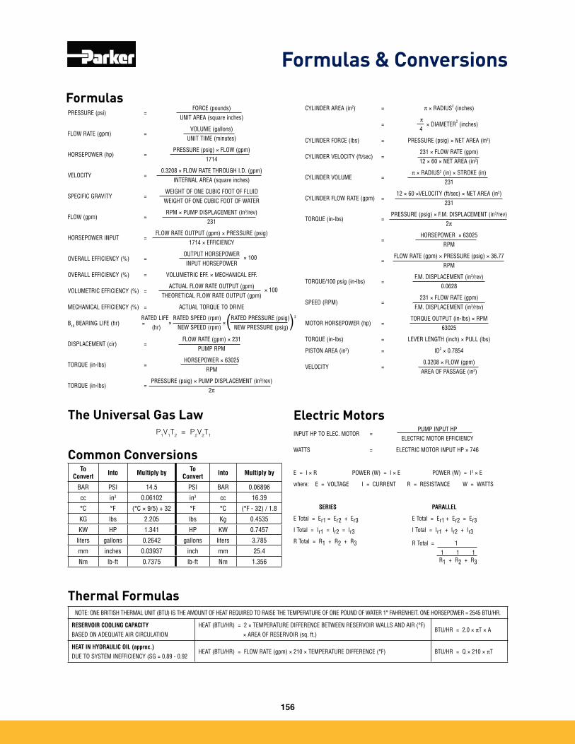
CYLINDER AREA (in2) = p × RADIUS2 (inches)
=p
× DIAMETER2 (inches)
4
CYLINDER FORCE (lbs) = PRESSURE (psig) × NET AREA (in2)
CYLINDER VELOCITY (ft/sec) =231 × FLOW RATE (gpm)12 × 60 × NET AREA (in2)
CYLINDER VOLUME =p × RADIUS2 (in) × STROKE (in)
231
CYLINDER FLOW RATE (gpm) =12 × 60 ×VELOCITY (ft/sec) × NET AREA (in2)
231
TORQUE (in-lbs) =PRESSURE (psig) × F.M. DISPLACEMENT (in3/rev)
2p
=HORSEPOWER × 63025
RPM
=FLOW RATE (gpm) × PRESSURE (psig) × 36.77
RPM
TORQUE/100 psig (in-lbs) =F.M. DISPLACEMENT (in3/rev)
0.0628
SPEED (RPM) =231 × FLOW RATE (gpm)
F.M. DISPLACEMENT (in3/rev)
MOTOR HORSEPOWER (hp) =TORQUE OUTPUT (in-lbs) × RPM
63025
TORQUE (in-lbs) = LEVER LENGTH (inch) × PULL (lbs)
PISTON AREA (in2) = ID2 × 0.7854
VELOCITY =0.3208 × FLOW (gpm)
AREA OF PASSAGE (in2)
PRESSURE (psi) =FORCE (pounds)
UNIT AREA (square inches)
FLOW RATE (gpm) =VOLUME (gallons)
UNIT TIME (minutes)
HORSEPOWER (hp) =PRESSURE (psig) × FLOW (gpm)
1714
VELOCITY =0.3208 × FLOW RATE THROUGH I.D. (gpm)
INTERNAL AREA (square inches)
SPECIFIC GRAVITY =WEIGHT OF ONE CUBIC FOOT OF FLUIDWEIGHT OF ONE CUBIC FOOT OF WATER
FLOW (gpm) =RPM × PUMP DISPLACEMENT (in3/rev)
231
HORSEPOWER INPUT =FLOW RATE OUTPUT (gpm) × PRESSURE (psig)
1714 × EFFICIENCY
OVERALL EFFICIENCY (%) =OUTPUT HORSEPOWER × 100INPUT HORSEPOWER
OVERALL EFFICIENCY (%) = VOLUMETRIC EFF. × MECHANICAL EFF.
VOLUMETRIC EFFICIENCY (%) =ACTUAL FLOW RATE OUTPUT (gpm) × 100
THEORETICAL FLOW RATE OUTPUT (gpm)
MECHANICAL EFFICIENCY (%) = ACTUAL TORQUE TO DRIVE
B10 BEARING LIFE (hr) =
DISPLACEMENT (cir) =FLOW RATE (gpm) × 231
PUMP RPM
TORQUE (in-lbs) =HORSEPOWER × 63025
RPM
TORQUE (in-lbs) =PRESSURE (psig) × PUMP DISPLACEMENT (in3/rev)
2p
RATED LIFE×
(hr)RATED SPEED (rpm)
×NEW SPEED (rpm)
RATED PRESSURE (psig) 3
NEW PRESSURE (psig)( )
Common ConversionsTo
Convert Into Multiply by To Convert Into Multiply by
BAR PSI 14.5 PSI BAR 0.06896
cc in3 0.06102 in3 cc 16.39
°C °F (°C × 9/5) + 32 °F °C (°F - 32) / 1.8
KG lbs 2.205 lbs Kg 0.4535
KW HP 1.341 HP KW 0.7457
liters gallons 0.2642 gallons liters 3.785
mm inches 0.03937 inch mm 25.4
Nm lb-ft 0.7375 lb-ft Nm 1.356
Thermal FormulasNOTE: ONE BRITISH THERMAL UNIT (BTU) IS THE AMOUNT OF HEAT REQUIRED TO RAISE THE TEMPERATURE OF ONE POUND OF WATER 1° FAHRENHEIT. ONE HORSEPOWER = 2545 BTU/HR.
RESERVOIR COOLING CAPACITYBASED ON ADEQUATE AIR CIRCULATION
HEAT (BTU/HR) = 2 × TEMPERATURE DIFFERENCE BETWEEN RESERVOIR WALLS AND AIR (°F) × AREA OF RESERVOIR (sq. ft.)
BTU/HR = 2.0 × pT × A
HEAT IN HYDRAULIC OIL (approx.)DUE TO SYSTEM INEFFICIENCY (SG = 0.89 - 0.92
HEAT (BTU/HR) = FLOW RATE (gpm) × 210 × TEMPERATURE DIFFERENCE (°F) BTU/HR = Q × 210 × pT
Electric MotorsINPUT HP TO ELEC. MOTOR =
PUMP INPUT HPELECTRIC MOTOR EFFICIENCY
WATTS = ELECTRIC MOTOR INPUT HP × 746
E = I × R POWER (W) = I × E POWER (W) = I2 × E
where: E = VOLTAGE I = CURRENT R = RESISTANCE W = WATTS
SERIES PARALLEL
E Total = Er1 = Er2 + Er3 E Total = Er1 + Er2 = Er3
I Total = Ir1 = Ir2 = Ir3 I Total = Ir1 + Ir2 + Ir3
R Total = R1 + R2 + R3 R Total = 1 1 1 1
R1 + R2 + R3
Formulas
The Universal Gas LawP1V1T2 = P2V2T1
Formulas & Conversions
156
Offer of Sale
157
The items described in this document and other documents and descriptions provided by Parker Hannifin Corporation, Hydraulics Group, and its authorized distributors (“Seller”) are hereby offered for sale at prices to be established by Seller� This offer and its acceptance by any customer (“Buyer”) shall be governed by all of the following Terms and Conditions� Buyer’s order for any item described in its document, when communicated to Seller verbally, or in writing, shall constitute acceptance of this offer� All goods or work described will be referred to as “Products”�
1. Terms and Conditions. Seller’s willingness to offer Products, or accept an order for Products, to or from Buyer is expressly conditioned on Buyer’s assent to these Terms and Conditions and to the terms and conditions found on-line at www�parker�com/saleterms/� Seller objects to any contrary or additional term or condition of Buyer’s order or any other document issued by Buyer�2. Price Adjustments; Payments. Prices stated on the reverse side or preceding pages of this document are valid for 30 days� After 30 days, Seller may change prices to reflect any increase in its costs resulting from state, federal or local legislation, price increases from its suppliers, or any change in the rate, charge, or classification of any carrier� The prices stated on the reverse or preceding pages of this document do not include any sales, use, or other taxes unless so stated specifically� Unless otherwise specified by Seller, all prices are F�O�B� Seller’s facility, and payment is due 30 days from the date of invoice� After 30 days, Buyer shall pay interest on any unpaid invoices at the rate of 1�5% per month or the maximum allowable rate under applicable law�3. Delivery Dates; Title and Risk; Shipment. All delivery dates are approximate and Seller shall not be responsible for any damages resulting from any delay� Regard-less of the manner of shipment, title to any products and risk of loss or damage shall pass to Buyer upon tender to the carrier at Seller’s facility (i�e�, when it’s on the truck, it’s yours)� Unless otherwise stated, Seller may exercise its judgment in choosing the carrier and means of delivery� No deferment of shipment at Buyers’ request beyond the respective dates indicated will be made except on terms that will indemnify, defend and hold Seller harmless against all loss and additional expense� Buyer shall be responsible for any additional shipping charges incurred by Seller due to Buyer’s changes in shipping, product specifications or in accordance with Section 13, herein�4. Warranty. Seller warrants that the Products sold hereunder shall be free from defects in material or workmanship for a period of eighteen months from the date of delivery to Buyer� The prices charged for Seller’s products are based upon the exclu-sive limited warranty stated above, and upon the following disclaimer: DISCLAIMER OF WARRANTY: THIS WARRANTY COMPRISES THE SOLE AND ENTIRE WARRANTY PERTAINING TO PRODUCTS PROVIDED HEREUNDER� SELLER DISCLAIMS ALL OTHER WARRANTIES, EXPRESS AND IMPLIED, INCLUDING MERCHANTABILITY AND FITNESS FOR A PARTICULAR PURPOSE�5. Claims; Commencement of Actions. Buyer shall promptly inspect all Products upon delivery� No claims for shortages will be allowed unless reported to the Seller within 10 days of delivery� No other claims against Seller will be allowed unless asserted in writing within 60 days after delivery or, in the case of an alleged breach of warranty, within 30 days after the date within the warranty period on which the defect is or should have been discovered by Buyer� Any action based upon breach of this agreement or upon any other claim arising out of this sale (other than an action by Seller for any amount due to Seller from Buyer) must be commenced within thirteen months from the date of tender of delivery by Seller or, for a cause of action based upon an alleged breach of warranty, within thirteen months from the date within the warranty period on which the defect is or should have been discovered by Buyer�6. LIMITATION OF LIABILITY. UPON NOTIFICATION, SELLER WILL, AT ITS OPTION, REPAIR OR REPLACE A DEFECTIVE PRODUCT, OR REFUND THE PURCHASE PRICE� IN NO EVENT SHALL SELLER BE LIABLE TO BUYER FOR ANY SPECIAL, INDIRECT, INCIDENTAL OR CONSEQUENTIAL DAMAGES ARISING OUT OF, OR AS THE RESULT OF, THE SALE, DELIVERY, NON-DELIVERY, SERVICING, USE OR LOSS OF USE OF THE PRODUCTS OR ANY PART THEREOF, OR FOR ANY CHARGES OR EXPENSES OF ANY NATURE INCURRED WITHOUT SELLER’S WRITTEN CONSENT, EVEN IF SELLER HAS BEEN NEGLIGENT, WHETHER IN CONTRACT, TORT OR OTHER LEGAL THEORY� IN NO EVENT SHALL SELLER’S LIABILITY UNDER ANY CLAIM MADE BY BUYER EXCEED THE PURCHASE PRICE OF THE PRODUCTS�7. Contingencies. Seller shall not be liable for any default or delay in performance if caused by circumstances beyond the reasonable control of Seller�8. User Responsibility. The user, through its own analysis and testing, is solely responsible for making the final selection of the system and Product and assuring that all performance, endurance, maintenance, safety and warning requirements of the application are met� The user must analyze all aspects of the application and follow applicable industry standards and Product information� If Seller provides Product or system options, the user is responsible for determining that such data and specifications are suitable and sufficient for all applications and reasonably foresee-able uses of the Products or systems�9. Loss to Buyer’s Property. Any designs, tools, patterns, materials, drawings, confidential information or equipment furnished by Buyer or any other items which become Buyer’s property, may be considered obsolete and may be destroyed by Seller after two consecutive years have elapsed without Buyer placing an order for the items which are manufactured using such property� Seller shall not be responsible for any loss or damage to such property while it is in Seller’s possession or control�10. Special Tooling. A tooling charge may be imposed for any special tooling, including without limitation, dies, fixtures, molds and patterns, acquired to manufacture Products� Such special tooling shall be and remain Seller’s property notwithstanding payment of any charges by Buyer� In no event will Buyer acquire any interest in apparatus belonging to Seller which is utilized in the manufacture of the Products, even if such apparatus has been specially converted or adapted for such manufacture and notwithstanding any charges paid by Buyer� Unless otherwise agreed, Seller shall have the right to alter, discard or otherwise dispose of any special tooling or other property in its sole discretion at any time�
11. Buyer’s Obligation; Rights of Seller. To secure payment of all sums due or otherwise, Seller shall retain a security interest in the goods delivered and this agreement shall be deemed a Security Agreement under the Uniform Commercial Code� Buyer authorizes Seller as its attorney to execute and file on Buyer’s behalf all documents Seller deems necessary to perfect its security interest� Seller shall have a security interest in, and lien upon, any property of Buyer in Seller’s possession as security for the payment of any amounts owed to Seller by Buyer�12. Improper Use and Indemnity. Buyer shall indemnify, defend, and hold Seller harmless from any claim, liability, damages, lawsuits, and costs (including attorney fees), whether for personal injury, property damage, patent, trademark or copyright infringement or any other claim, brought by or incurred by Buyer, Buyer’s employees, or any other person, arising out of: (a) improper selection, improper application or other misuse of Products purchased by Buyer from Seller; (b) any act or omission, negligent or otherwise, of Buyer; (c) Seller’s use of patterns, plans, drawings, or specifications furnished by Buyer to manufacture Product; or (d) Buyer’s failure to comply with these terms and conditions� Seller shall not indemnify Buyer under any circumstance except as otherwise provided�13. Cancellations and Changes. Orders shall not be subject to cancellation or change by Buyer for any reason, except with Seller’s written consent and upon terms that will indemnify, defend and hold Seller harmless against all direct, incidental and consequential loss or damage� Seller may change product features, specifications, designs and availability with notice to Buyer�14. Limitation on Assignment. Buyer may not assign its rights or obligations under this agreement without the prior written consent of Seller�15. Entire Agreement. This agreement contains the entire agreement between the Buyer and Seller and constitutes the final, complete and exclusive expression of the terms of the agreement� All prior or contemporaneous written or oral agreements or negotiations with respect to the subject matter are herein merged� 16. Waiver and Severability. Failure to enforce any provision of this agreement will not waive that provision nor will any such failure prejudice Seller’s right to enforce that provision in the future� Invalidation of any provision of this agreement by legislation or other rule of law shall not invalidate any other provision herein� The remaining provisions of this agreement will remain in full force and effect�17. Termination. This agreement may be terminated by Seller for any reason and at any time by giving Buyer thirty (30) days written notice of termination� In addition, Seller may by written notice immediately terminate this agreement for the following: (a) Buyer commits a breach of any provision of this agreement (b) the appointment of a trustee, receiver or custodian for all or any part of Buyer’s property (c) the filing of a petition for relief in bankruptcy of the other Party on its own behalf, or by a third party (d) an assignment for the benefit of creditors, or (e) the dissolution or liquidation of the Buyer�18. Governing Law. This agreement and the sale and delivery of all Products here-under shall be deemed to have taken place in and shall be governed and construed in accordance with the laws of the State of Ohio, as applicable to contracts executed and wholly performed therein and without regard to conflicts of laws principles� Buyer irrevocably agrees and consents to the exclusive jurisdiction and venue of the courts of Cuyahoga County, Ohio with respect to any dispute, controversy or claim arising out of or relating to this agreement� Disputes between the parties shall not be settled by arbitration unless, after a dispute has arisen, both parties expressly agree in writing to arbitrate the dispute� 19. Indemnity for Infringement of Intellectual Property Rights. Seller shall have no liability for infringement of any patents, trademarks, copyrights, trade dress, trade secrets or similar rights except as provided in this Section� Seller will defend and indemnify Buyer against allegations of infringement of U�S� patents, U�S� trademarks, copyrights, trade dress and trade secrets (“Intellectual Property Rights”)� Seller will defend at its expense and will pay the cost of any settlement or damages awarded in an action brought against Buyer based on an allegation that a Product sold pursuant to this Agreement infringes the Intellectual Property Rights of a third party� Seller’s obligation to defend and indemnify Buyer is contingent on Buyer notifying Seller within ten (10) days after Buyer becomes aware of such allegations of infringement, and Seller having sole control over the defense of any allegations or actions including all negotiations for settlement or compromise� If a Product is subject to a claim that it infringes the Intellectual Property Rights of a third party, Seller may, at its sole expense and option, procure for Buyer the right to continue using the Product, replace or modify the Product so as to make it noninfringing, or offer to accept return of the Product and return the purchase price less a reasonable allowance for depreciation� Notwithstanding the foregoing, Seller shall have no liability for claims of infringement based on information provided by Buyer, or directed to Products delivered hereunder for which the designs are specified in whole or part by Buyer, or infringements resulting from the modification, combination or use in a system of any Product sold hereunder� The foregoing provisions of this Section shall constitute Seller’s sole and exclusive liability and Buyer’s sole and exclusive remedy for infringement of Intellectual Property Rights�20. Taxes. Unless otherwise indicated, all prices and charges are exclusive of excise, sales, use, property, occupational or like taxes which may be imposed by any taxing authority upon the manufacture, sale or delivery of Products�21. Equal Opportunity Clause. For the performance of government contracts and where dollar value of the Products exceed $10,000, the equal employment opportunity clauses in Executive Order 11246, VEVRAA, and 41 C�F�R� §§ 60-1�4(a), 60-741�5(a), and 60-250�4, are hereby incorporated�
System RequirementsTo view the DVD, the following are required:
• Pentium®3-classprocessor• Win2000,WinXP,WinVistaorWin7
• 32MBofRAM• 1GBofavailablehard-diskspace
• DVDplayer
Acrobat ReaderCatalog files are viewed using Adobe Acrobat Reader. If you do not have Acrobat Reader installed on your PC, Win Vista, Win 7 and most Win XP systems will give you an web install option for Acrobat Reader on the bottom of the DVD install menu.You must have Acrobat 6.0 or higher to take advantage of the search feature described in the next section.
To View the DVDThe DVD is self-loading. Just place it in your DVD drive. Acrobat Reader will open (or install), and the opening page will appear on your monitor. From this page you can navigate to the following sections.
• Search*takesyoutothesearch feature.Whenthesearch windowopens,typeaword(s) orcode*andpressenter.A listofpageswherethatword appearsisshown.Selectone andclicktheViewbutton. Repeatasneeded.
• ProductInformationor Contentstakesyoutothe selectionofcatalogsand productsontheDVD.
• ProductOverviewtakesyoutoa.pdffileofthis Hydraulic Pump and Power Systems Division ProductRange.
• Warning/OfferofSaletakesyoutotheselegaldocuments.
• GettingStartedprovidesasummaryofhowtonavigateusingAcrobatReader.
• ContactUsprovidesyouwithphone,faxandonlineinformation.
Text links are easily identified by blue type. The catalog files are fully bookmarked to make navigation quick and easy. Each catalog also has a bookmark which will take you to the Parker web home page if you are online while you are viewing the DVD.
Adobe and Acrobat are registered trademarks of Adobe Systems Inc.
Windows is a registered trademark of Microsoft Corp.
Catalog HY28-2673-01/HPD/US 04/2013 Web Only
© 2013 Parker Hannifin Corporation, all rights reserved
Parker Hannifin Corporation Hydraulics Pump and Power Systems Division 14249 Industrial Parkway Marysville, OH 43040 Tel: 937-644-4532Fax: 937-642-3639www.parker.com/hps