Hydraulic Power Units Vertical Mount - Airline Hydraulics
32
Transcript of Hydraulic Power Units Vertical Mount - Airline Hydraulics

2 Hydraulic power units, vertical mount, fixed displacement gear pumps
D03/NG6 Bar I
Return Line Filter ‘
Tank
Assembly
Air Breather/Filler Cap
Oil Level Gage
w/Thermometer

Hydraulic power units, vertical mount, fixed displacement gear pumps 3
1A complete standard power unit program featuring: I
~ A full range of standard sizes . . .1.7,2.6, and 6.9 gallon aluminum reservoirs,
10, 15, and 25 gallon steel reservoirs.
Z Pump flow rates of 0.5 to 10.4 GPM.
Z System pressures ranging from 250 to 3,625 PSI.
3 Vertically mounted electric motors in sizesfrom 1/3 to 20 HP.
Z In-tank return line filter enables compact design
and reduces possibility of oil spillage during element
change (an important environmental concern).
2 Filter has a removable bowl which preventscontamination from entering reservoir during
filter element change.
~ Steel reservoirs feature a slanted bottom tofacilitate draining of unit and contaminate removal.
Z All units include a drain port to simplify oil changing.
❑ Oil level gage with thermometer for easy check offluid level and temperature
❑ Optional bar manifolds, heat exchanger and/oraccessories can be specified to form a complete
compact system.
❑ All units are fully assembled, tested and painted.

4 Hydraulic power units, vertical mount, fixed displacement gear pumps
Index
Aluminum Tank
Tank Size Pump Flow Rate Motor Size Page Number
1.7 Gallon 0.49 to 0.73 GPM l/3tol-l/2HP 6-9
6 Liter 1.86 to 2.76 L/rein,
2.6 Gallon 0.49 to 0.98 GPM l/3t02HP 10-1310 Liter 1,86 to 3.71 L/rein,
6,9 Gallon 1,47 to 2.57 GPM l/3to 7-1/2 HP 14-17
26 Liter 5.56 to 9.73 Llmin.
Steel Tank
Tank Size Pump Flow Rate Motor Size Page Number
10 Gallon 1,81 to 3.72 GPM l/2to10HP 18-21
38 Liter 6,85 to 14.04 L/rein.
15 Gallon 3,71 to 6,43 GPM 1 to 20 HP 22-25
57 Liter 14.04 to 24,34 Llmin.! i 1
25 Gallon 7.41 to 10.37 GPM 2 to 20 HP 26-2995 Liter 28.05 to 39,25 L/rein.
I Accessories
Heat Exchanger 30
Water Modulating ValveI 30
D03/NG6 Bar Manifold 31
I Specifying / Ordering Procedure:
1. Pump Flow Rate/ Tank Size
2. Pressure/ Horsepower
3. Accessories/ Options
Specifying Example:
Start your selection process in the Index above. The Pump Flow Rate and the Tank Size
should lead you to the catalog pages for the Hydraulic Power Unit you require.
Based upon your selection in (1.) above, the first page of that section features the Selection
Chart/Ordering Pati Numbers. This chart enables you to further refine your selection accord-
ing to pressure and horsepower. In the same chart, you can choose which Hydraulic Power
Unit you require (with Pressure Relief Valve or with Bar Manifold and Relief Valve Module),
Specify this Part Number on your purchase order.
For convenience, the Bar Manifold Selection Chart and the Accessory Selection Chart
are on the same page with the Selection Chart/Ordering Par-1Numbers.
Select the Bar Manifold and Directional/Modular Valves, as required,
Select the desired Accessories,
Specify the Part Number for each optional item on your purchase order, together with
the Power Unit Patt Number you have chosen.
If requirements are: ● a flow rate of 0.6 GPM,
● a 2-1/2 gallon tank,
● and a pressure maximum of 1500 PSI,
● with a pressure relief valve.
The index would lead you to page 10 of this catalog. In the Selection Chart/Ordering Pat-l
Numbers, you would see that the second pump with 0.097 in’ displacement will assure a
flow rate of at least 0.6 GPM. And a 3/4 HP Motor will deliver up to the 1500 PSI you require,
Selecting the Power Unit with Pressure Relief Valve identifies Part Number 9815230144
to specify on your purchase order.
If your application also requires a Visual Filter Clogging Indicator, you would find that in the
Accessory Chart on the same page and add Patt Number 9815230106 to your specification,

Hydraulic power units, vertical mount, fixed displacement gear pumps 5
1Technical Specifications
General
Tank Sizes I 1.7, 2.6, 6.9 Gallon Aluminum Die Cast
10, 15, 25 Gallon Welded Steel
Gear Pumps 112 to 10-1/4 GPM
Electric Motors 113 to 20 HP at 1750 RPM,
C-Face, TEFC 230/460/3/60 (Other voltages per request)
I Installation Position I Vertical Mount Pump/Motor Group
I ODeratina Pressure I Reference Individual PumriMotor Selection Charts I
I Hydraulic Fluid I Petroleum based hydraulic oil “1Fluid Temperature 5° Fto 176°F (–15° Cto 80’C)
Seals Buna N
Standard Equipment
Accessories
Drain Plug – Sight Glass – Filler/Breather –
Return Filter: 10 Micron - Drain Port – Gage Port –
Sensing Port for Optional Water Valve (Steel tanks only)
Relief Block/Valve – D03/NG6 Bar Manifold: 1 to 5 Station with
Relief Module - Filter Indicators - Water Valve (Steel tanks only) -
Heat Exchanaer (Steel tanks onlv)
I Valving \ Reference Bosch Catalogs for Directional Control and Modular Valves I
I Scope of Supply I Units are completely assembled, as selected from the following
selection charts, tested and painted II Reference I
Catalog Catalog Number
Gear Pumps: HPUS-AKYOOl/3US(4-92)
Pressure Relief Valve: 1987760701
Direction Control Valves 571102
D03/NG6 HPus-AKYoo6/18us
Modular Valves D03/NG6: HPUS-AKYO1 0/1 US(6.90)
Price
SEE ‘PRICE LIST HYDRAULIC POWER UNIT, VERTICAL MOUNT, FIXED DISPLACEMENT GEAR PUMPS”
I Product Literature Disclaimer I
SPECIFICATIONS AND/OR DIMENSIONS ARE SUBJECT TO CHANGE WITHOUT PRIOR NOTICE. PLEASE CONSULT FACTORY.

6 Hydraulic power units, vertical mount, fixed displacement gear pumps
1 I I I
~ 1.7 Gallon/6 Liter Aluminum Tank II Specifying/Ordering Procedure : See page 4. ~1
I Selection Chart/Orderina Part Numbers
Tank
Volume
Gallon
(Liter)
1.7
(6)
Pump
Displacement
Ins/Rev
(cm’/Rev)
.065
(1 .06)
.097
(1 .59)
Flow
@l 750 RPM
GPM
(L/rein)
,492
(1 ,86)
,73
(2.76)
113 950 66 9815230120
112 1450 100 9815230121
314 2200 152 9815230122
1 2950 204 9815230123
1t3 650 45 9815230124
112 1000 69 9815230125
314 1500 104 9815230126
1 2000 138 98152301271y2 3000 207 9815230128
Standard Power Units Include:Tank with Drain Plug Return Line Filter
~
Oil Level Gage with Thermometer Pressure Relief BlockAir Breather/Filler Cap Drain Connection (DR)Pump/ Motor Assembly Pressure Gage Connection (GA)
All Units are Completely Assembled, Tested and Painted.
Power Unit with Bar
Manifold (D03/NG6)
w/Relief Vlv. Module
Part Number
9815230129
9815230130
9815230131
9815230132
9815230133
9815230134
9815230135
9815230136
9815230137
Select Bar Manifold
below.
Select Accessories
below, if desired.
Bar Manifold Selection Chart
Manifold Type Reference Description Part Number
Bar Manifold See page 31.
(D03/NG6)
I
Directional Control Valves See page 31.
1 Valve Station with Relief Valve Module
2 Valve Stations with Relief Valve Module
3 Valve Stations with Relief Valve Module
4 Valve Stations with Relief Valve Module
5 Valve Stations with Relief Valve Module
See Bosch Cataloa “Directional Control Valve D03°
98152301019815230102981523010398152301049815230105
Select from cataloa.
~Modular Valves
1
See page 31, I For Check, Reducing, Flow Control and Relief Valves, I Select from catalog.
see Bosch Catalog “Modular Valves DO-3 (NG-6)”
I Accessory Selection Chart IAccessory Reference Description Part Number
I Filter Clogging Indicator II
Visual (Gage) 9815230106
Electrical (Pressure Switch) 250 VAC 9815230107
Electrical with Light (DIN Plug with Light 24 Volt DC) 9815230108
Electrical with Light (DIN Plug with Light 115 Volt AC) 9815230109
Electrical with Light (DIN Plug with Light 230 Volt AC) 9815230110

Hydraulic power units, vertical mount, fixed displacement gear pumps 7
11.7 Gallon/6 Liter Aluminum Tank
Standard Power Unit with Pressure Relief Valve
DR
#6 SAE
GA. P. T
‘4sA-‘1----
—7 ‘–-
14
II
11
B)x
10
#8 SAE
9
%’ 5
Features:1. Tank
2. Tank Drain Plug
3. Oil Level Gage w/Thermometer
4. Steel cover
5. Air Breather/Filter Cap
6. Pump/Motor Assembly
7. Pressure Relief Valve
8, Return Line Filter
9. Optional Visual Indicator10, Optional Electrical Indicator
11, Optional Electrical Indicator w/Light
Standard Power Unit with D03/NG6 Bar Manifold and Pressure Relief Valve Module
DR
#6 SAE
l–- lL–– —–— —J –-
Features:
1. Tank
2. Tank Drain Plug
3, Oil Level Gage w/Thermometer
4. Steel cover
5. Air Breather/Filter Cap
6. Pump/Motor Assembly
7. Return Line Filter
8. Optional Visual Indicator
9. Optional Electrical Indicator
10. Optional Electrical Indicator w/Light
11. Optional D03/NG6 Bar Manifold with Pressure
Relief Valve Module Available in 1 thru 5 Stations,
14 12X

8 Hydraulic power units, vertical mount, fixed displacement gear pumps
I 1.7 Gallon/6 Liter Aluminum Tank
Standard Power Unit with Pressure Relief Valve
~~
GA#4 SAE GAGECONNECTION
‘1
(3’5:
.
641)
I
I
H5,120(130.00)
— 7.875 —(200.00)
Inches (Millimeters)
PRESSURE DRRELIEF VALVE 37” FLARE
P#8 SAE
PRESSURECONNECTION
AIR BREATHER& FILLER CAP
A/’\RETURN LINEFILTER
II T
1/3HP=17562(446,07)
1/2HP=17.562(446.07)
3/4HP =1 7.562(446.07)
#8 SAERETURN
CONNECTION
1HP=18.500I (470.90)
OIL LEVEL >1-1/2HP=18.500
(470,90)GAGE WITH
THERMOMETER
r(4) M8MOUNTING HOLESTAPPED .375” (9.53)DEEP
1-0.688(17,48)
1.376 _(35,00)
-
L G 114 TANKDRAIN PLUG
~ 8.270 _(210.00)
—~l.023—(280.00)
— 10.562 —(288.27)
_l ~ 13.000(330.20) -
7.254(184.25)
J

Hydraulic power units, vertical mount, fixed displacement gear pumps 9
1.7 Gallon/6 Liter Aluminum Tank
Standard Power Unit with D03/NG6 Bar Manifold and Pressure Relief Valve Module Inches (Millimeters)
D031NG6 BARMANIFOLD AND
PRESSURE RELIEFVALVE MODULE
1 DR
GA#4 SAE GAGECONNECTION
I
1.376(35.00) -
~J
lr(53j2:o)-
0.437- *(11 .09) 7.875
(200.00)
l/3 HP=17.562(446.07)
112HP =1 7,562(446.07)
314HP =1 7,562(446.07)
1HP=18500(470.90)
1-1/2HP=18.500(470,90)
(4) M6MOUNTING HOLESTAPPED .375” (9.53)DEEP
RET”RN LINE ~ WFILTER
#8 SAECUSTOMER
CONNECTIONS(FAR SIDq
THE:
)
~G I,4TANKDRAIN PLUG

10 Hydraulic power units, vertical mount, fixed displacement gear pumps
2.6 Gallon/10 Liter Aluminum Tank Specifying/Ordering Procedure : See page 4.
Selection Chart/Ordering Part Numbers
FTank
Volume
Gallon
(Liter)
2.6
(1 o)
Pump
Displacement
In’/Rev
(cm’/Rev)
.065
(1 ,06)
Flow
@J1750F
GPM(Llmin)
.492
(1 .66)
Power Unit with
Pressure Relief Va
Part Number
Power Unit with Bar
Manifold (D03/NG6)
w/Relief Vlv. Module
Motor
HP
Pressure Max @ HP
bar
66
100
152
204
45
69
104
136
207
35
52
76
104
155
207
Psl
9501450
22002950
Pati Number
98152301531131/2
3141
9815230138981523013998152301409815230141
981523015498152301559815230156
.097(1 .59)
.73
(2,76)
.98
(3.71)
113
112
3141
65010001500
20003000
98152301429815230143981523014498152301459815230146
981523015798152301589815230159981523016098152301611 1/2
.129
(2,11)
1/311231411y,
2
500750
11001500
22503000
981523014798152301489815230149981523015098152301519815230152
981523016298152301639815230164981523016598152301669815230167
Select Accessories
below, if desired.
Select Bar Manifold
below.Standard Power Units IncludeTank with Drain PIUCI Return Line Filter Select Accessories
below, if desired,Oil Level Gage with-Thermometer Pressure Relief BlockAir Breather/Filler Ca~ Drain Connection (DR)Pump/ Motor Assembly Pressure Gage Connection (GA)
All Units are Completely Assembled, Tested and Painted.
I 1
I Bar Manifold Selection Chart I
Manifold Tv~e Reference
See page 31.
Description Part Number
1 Valve Station with Relief Valve Module 9815230101
2 Valve Stations with Relief Valve Module 9815230102
3 Valve Stations with Relief Valve Module 9815230103
4 Valve Stations with Relief Valve Module 9815230104
5 Valve Stations with Relief Valve Module 9815230105
See Bosch Catalog “Directional Control Valve D03° Select from catalog,
For Check, Reducing, Flow Control and Relief Valves, Select from catalog,
see Bosch Catalog “Modular Valves DO-3 (NG-6)”
Bar Manifold
(D03/NG6)
See page 31.
See page 31.
I Directional Control Valves
Accessory Selection Chart
Accessory Reference Description Part Number
Filter Clogging Indicator Visual (Gage) 9815230106
Electrical (Pressure Switch) 250 VAC 9815230107
Electrical with Light (DIN Plug with Light 24 Volt DC) 9815230108
Electrical with Light (DIN Plug with Light 115 Volt AC) 9815230109
Electrical with Light (DIN Plug with Light 230 Volt AC) 9815230110

Hydraulic power units, vertical mount, fixed displacement gear pumps 11
I 2.6 Gallon/10 Liter Aluminum Tank
Standard Power Unit with Pressure Relief Valve
5$5z
w~ o
; ~ !$$F
ZtiZz Iuz ~z ~z<z Dz ~z =ZKO ao Lono 00 EE3 ‘xO
DR=GA=P= .T Features:#6 SAE #4 SAE #8 SAE Z #l 2 SAE 1. Tank— ——— ——
,12. Tank Drain Plug
3. Oil Level Gage wflhermometer
t J 4, Steel cover——— ——— -7 5, Air Breather/Filter Cap
6, Pump/Motor Assembly
7, Pressure Relief Valve
8. Return Line Filter
9. Optional Visual Indicator
10. Optional Electrical Indicator
11. Optional Electrical Indicator w/Light
[ 83
14 21
Standard Power Unit with D03/NG6 Bar Manifold and Pressure Relief Valve Module
z z z zo 6 ~Q Kg WsFg ~
u+25 20 !+5
Zz Wz py py py
~~ :5 ~g~z (J-JZ30 3000 00
Features:1. Tank
2. Tank Drain Plug
3. Oil Level Gage wllhermometer
4. Steel cover
5. Air Breather/Filter Cap
6. Pump/Motor Assembly
7. Return Line Filter
8. Optional Visual Indicator9. Optional Electrical Indicator
10. Optional Electrical Indicator w/Light
11. Optional D03/NG6 Bar Manifold with Pressure
Relief Valve Module Available in 1 thru 5 Stations.

12 Hydraulic power units, vertical mount, fixed displacement gear pumps
2.6 Gallon/10 Liter Aluminum Tank
Standard Power Unit with Preseure Relief Valve
1.51538.50) -
II
_ 9.723 ~(247,00)
10.500 —.(266.70)
1
l/3 HP=1g.187(487.35)
l/2 HP=1g.187(487,35)
3/4 HP=1g,187(487.35)
1HP=20125(511.18)
l-1/2HP =20,125(51 1.18)
2HP=21.125(536.58)
(4)M8MOUNllNG HOLESTAFPED.375 (9.53)DEEP
Inches (Millimeters)
T DR#12 SAE 37° FLARE
FRESSURE & FILLERCAPCONNECTION
)
0“750~:=11(19.05)

Hydraulic power units, vertical mount, fixed displacement gear pumps 13
2.6 Gallon/10 Liter Aluminum Tank
Standard Power Unit with D03/NG6 Bar Manifold and Pressure Relief Valve Module Inches (Millimeters)
DR37” FL4RE
r
6) DRAIN
nCONNECllON
RETURNLINEFILTER
DOWNG6 BARMANIFOLDAND
FRESSURERELIEFVALVEMODULE
#8 SAE GACUSTOMER #4 SAE GAGE CONNECTION
/
CONNECTIONS
\
1.515-(38.50)
I A
1
I
Illw
II [G 114 TANKDRAIN PLUG
Im
l/3 HP:19187(487.35)
l/2 HP=1g187(487.35)
3/4 HP=1g187(487,35)
1HP =20.1 25(511.18)
-1/2HP =20.125(511.18)
2HP=21.125(536,58) )
(4’4
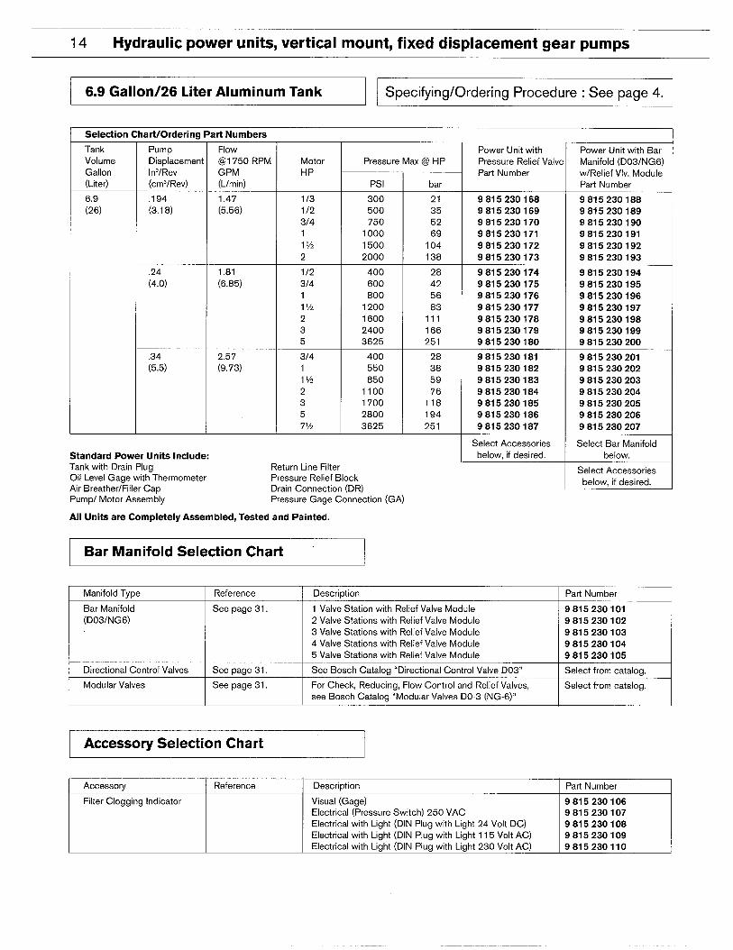
14 Hydraulic power units, vertical mount, fixed displacement gear pumps
6.9 Gallon/26 Liter Aluminum Tank Specifying/Ordering Procedure : See page 4.
Selection
Tank
art/Ord[
Pump
Displac
In’/Rev
(cm’/Rc
.194
(3.1 8)
,24
(4.0)
.34(5.5)
art Numbers
Flow
(@I 750 RPM
GPM
(L/rein)
1,47
(5.56)
Power Unit with
Pressure Relief L
Part Number
Power Unit with
Manifold (D03/F
w/Relief Vlv, Mo
Part Number
Volume
Gallon
(Liter)
Pressure Max @ HP
HP
Psl bar
6.9
(26)
113
112
3/4
111/2
2
300
500750
1000
1500
2000
21
35
52
69
104
138
9815230168
9815230169
9815230170
9815230171
9815230172
9815230173
9815230188
9815230189
9815230190
9815230191
9815230192
9815230193
1.81
(6.85)
112
3/4
1l%
2
3
5
314
11y!
2
3
57y2
400
600
800
1200
1600
2400
3625
400
550
850
1100
1700
2800
3625
28
42
56
83
111
166
251
28
38
59
76
118
194
251
9815230174
9815230175
9815230176
9815230177
9815230178
9815230179
9815230180
9815230194
9815230195
9815230196
9815230197
9815230198
9815230199
9815230200
2.57
(9,73)
9815230181
9815230182
9815230183
9815230184
9815230185
9815230186
9815230187
Select Accessories
below, if desired,
9815230201
9815230202
9815230203
9815230204
9815230205
9815230206
9815230207
Select Bar Manif
below.Standard Power Unita Include:Tank with Drain PIUQ Return Line Filter Select Accessor
below, if desireOil Level Gage with-Thermometer Pressure Relief BlockAir Breather/Filler Cao Drain Connection (DR)Pump/ Motor Assembly Pressure Gage Connection (GA)
All Units are Completely Assembled, Tested and Painted.
I Bar Manifold Selection Chart 1
Reference
See page 31.
Manifold Type Description
1 Valve Station with Relief Valve Module
2 Valve Stations with Relief Valve Module
3 Valve Stations with Relief Valve Module
4 Valve Stations with Relief Valve Module
5 Valve Stations with Relief Valve Module
See Bosch Catalog “Directional Control Valve D03°
For Check, Reducing, Flow Control and Relief Valves,
see Bosch Catalog “Modular Valves DO-3 (NG-6)”
Parl Number
IBar Manifold
(D03/NG6)
9815230101
9815230102
9815230103
9815230104
9815230105
Directional Control Valves See page 31.
See page 31.
Select from catalog.
Select from catalog.I Modular Valves
I Accessory Selection Chart
Accessory Reference Description Part Number
Filter Clogging Indicator Visual (Gage) 9815230106Electrical (Pressure Switch) 250 VAC 9815230107
Electrical with Light (DIN Plug with Light 24 Volt DC) 9815230108
Electrical with Light (DIN Plug with Light 115 Volt AC) 9815230109
Electrical with Light (DIN Plug with Light 230 Volt AC) 9815230110

Hydraulic power units, vertical mount, fixed displacement gear pumps 15
I 6.9 Gallon/26 Liter Aluminum Tank
Features:1. Tank
2. Tank Drain Plug
3. Oil Level Gage w/thermometer
4. Steel cover
5. Air Breather/Filter Cap
6. Pump/Motor Assembly
7. Pressure Relief Valve
8. Return Line Filter
9. Optional Visual Indicator
10. Optional Electrical Indicator
11. Optional Electrical Indicator w/Light
Standard Power Unit with Pressure Relief Valve
zo $6
z
u~o
F F F(-)-)~g z%
Zz Wz ~z ~z<z OZ ~z =’ZEo <0 FJOao 00 %: Kc)
DR. GA 7P= =T
#6 SAE #4 SAE #SSAE ?? #12 SAE—-- —.— —
1-—————— J
71
1
611
II 83
14 2A
Standard Power Unit with D03/NG6 Bar Manifold and Pressure Relief Valve Module
z z z z zO? @F
~Q &
g$ S6 !s6 26 Features:Zz WZ pg ~~ pg~z Oz g= (/)Z ~z 1. Tank
ctono SE 00
30 3000 00
2. Tank Drain Plug
3, Oil Level Gage wllhermometer
4. Steel cover
5. Air Breather/Filter Cap
6. Pump/Motor Assembly
7. Return Line Filter
8. Optional Visual Indicator
9. optional Electrical Indicator10. Optional Electrical Indicator w/Light
11. Optional D03/NG6 Bar Manifold with Pressure
Relief Valve Module Available in 1 thru 5 Stations.

16 Hydraulic power units, vertical mount, fixed displacement gear pumps
I 6,9 GalIon/26 Liter Aluminum Tank I
Standard Power Unit with Pressure Relief Valve Inches (Millimeters)
T#12 SAERETURN DR
CONNECTION 37” RARE
7 r
(#6) DFWNCONNECTION
REIURNUNE HLTER
PRESSUREREUEFVALVE
P/#8 SAE PRESSURE AIR BREATHER -“’”
CONNECTION & FILLER CAP
—1
I
I
I
o
3,22[[82.0(
6.930‘(1 76.00)–
— 13.390 —(340.00)
13,750
I(349.25)
l/3 HP= 21875(555.83)
1121-IP= p~e?~(555.63))
314HP= 21.875(555.63)
lHP= 22.812(579.42)
l-1/2 HP= 22.812(579.42)
2HP= 23312(592,1 2)
3HP= 25.125(638.16)
5HP = 26.500(673.10)
7-1/2 HP= 28125(714,36)
= (4) MIOMOUNTING HOLESTAPPED.593 (15)DEEP
GA#4 SAE GAGECONNECTION
3.22882.00)
[.
I
II
I
I
~ G112TPNKWR-UG
12.834 _(326.00)
19.290(490.00)
❑
I
20.000(508.00)
11.!(292
_OIL
~G:WITHTHERM.

Hydraulic power units, vertical mount, fixed displacement gear pumps 17
6.9 Gallon/26 Liter Aluminum Tank
Standard Power Unit with D031NG6 Bar Manifold and Pressure Relief Valve Module Inches (Millimeters)
DR37 FLARE(#6) DRAIN
/- CONNECTION
/
3,22[(82.0(
7
.
.
.
I
I
RETURNLINEFILTER
D031NG6BARMANIFOLD
FRE3S~R;RELIEFVALVE
MODULE
21,875(555.63)21.675(555,63)21.675(555,63)22.612(579,42)22.812(579.42)23.312(592.1 2)25.125(638.18)26,500(673.10)28,125(71 4.38)
Jy (4)M1OMOUNTING HOLES
_ 6.930TAFFED .593”(15)
(176.00)DEEP
4 H-2.560(65.03)
GA#4 SAE GAGE CONNECTION
\
mIzEII!m
.D
■
.
0■
3.226[82,00)
–(:0;::7
1GI,2TANKDRAINFLUG
I
I
.
[
12.834 —~(326,00)
19.290(490.00)
20.000(508.00)
I11.531
(292,89)OIL
$G:
THERM.

18 Hydraulic power units, vertical mount, fixed displacement gear pumps
I , I 1
I 10 Gallon/38 Liter Steel Tank II Specifying/Ordering Procedure : See page 4. II 1 I
Selection Chart/Ordering Part Numbers
Tank
Volume
Gallon
(Liter)
;;8)
Pump
Displacement
In’/Rev
(cm’/Rev)
.24
(4.0)
.34
(5.5)
,49(8,0)
Flow
@?l750 RPM
GPM
(Umin)
1,81
(6.85)
2.57
(9.73)
3.72
(1 4.04)
Motor
HP
1/2
314
1l%
2
3
5
314
11y2
2
3
571/2
Pressure Msx @ HP
Psl
400
600
800
1200
1600
2400
3625
400
550
850
1100
1700
2800
3625
350
550
750
1150
1950
2900
3625
Standard Power Units Include:Tank with Drain PlugOil Level Gage with ThermometerAir Breather/Filler CapPump/ Motor Assembly
Return Line FilterPressure Relief BlockDrain Connection (DR)Pressure Gage Connection (GA)
All Units are Completely Assembled, Tested and Painted.
Bar Manifold Selection Chart
bar
28
42
56
83
111
166
251
28
38
59
76
118
194
251
25
38
52
80
135
201
251
Power Unit with
Pressure Relief Valve
Part Number
9815230208
9815230209
9815230210
9815230211
9815230212
9815230213
9815230214
9815230215
9815230216
9815230217
9815230218
9815230219
9815230220
9815230221
9815230222
9815230223
9815230224
9815230225
9815230226
9815230227
9815230228
Select Accessories
below, if desired.
Power Unit with Bar
Manifold (D03/NG6)
w/Relief Vlv. Module
Part Number
9815230229
9815230230
9815230231
9815230232
9815230233
9815230234
9815230235
9815230236
9815230237
9815230238
9815230239
9815230240
9815230241
9815230242
9815230243
9815230244
9815230245
9815230246
9815230247
9815230248
9815230249
Select Bar Manifold
below.
Select Accessories
below, if desired.
Manifold Type Reference Description Part Number1
Bar Manifold See page 31, 1 Valve Station with Relief Valve Module 9815230101
(D03/NG6) 2 Valve Stations with Relief Valve Module 9815230102
3 Valve Stations with Relief Valve Module 9815230103
4 Valve Stations with Relief Valve Module 9815230104
5 Valve Stations with Relief Valve Module 9815230105
Directional Control Valves See page 31. See Bosch Catalog “Directional Control Valve D03° Select from catalog. I
I Modular Valves I See page 31.
~
For Check, Reducing, Flow Control and Relief Valves, ISelect from catalog.
see Bosch Catalog “Modular Valves DO-3 (NG-6)” 1
Accessory Selection Chart
Accessory Reference Description Part Number
Filter Clogging Indicator Visual (Gage)
Electrical (Pressure Switch) 250 VAC
Electrical with Light (DIN Plug with Light 24 Volt DC)
Electrical with Light (DIN Plug with Light 115 Volt AC)
Electrical with Light (DIN Plug with Light 230 Volt AC)
Heat Exchanger See page 30. Water to Oil 10 RB5-30 t
9815230106
9815230107
9815230108
9815230109
9815230110
9815230111 1Water Valve I See page 30. Modulating Valve w/Bulbwell 1/2 RB5-45-B 9815230112

Hydraulic power units, vertical mount, fixed displacement gear pumps 19
I 10 Gallon/38 Liter Steel Tank I
Standard Power Unit with Pressure Relief Valve
z zo 50 5 Features:
1. Tank
2. Tank Drain Plug6
3. Oil Level Gage w/Thermometer~
4. Steel cover
35. Air Breather/Filter Cap
6. Pump/Motor Assembly
~ 7. Pressure Relief Valve— 8. Return Line Filter
9. Optional Visual Indicator
10. Optional Electrical Indicator13
11. Optional Electrical Indicator w/Light
12. Optional Heat Exchanger
13. Optional Water Modulating Valve
Standard Power Unit with D03/NG6 Bar Manifold and Pressure Relief Valve Module
56E5 @ Es
~; g~ >0 !45Features:
py p$ 1. Tank
gg $5 ~g mz
d8 %
2. Tank Drain Plug
3. Oil Level Gage wflhermometer
DR. GA- A.-B AB-- AB 4. Steel cover. .5. Air Breather/Filter Cap
6. Pump/Motor Assembly
7. Return Line Filter
8. Optional Visual Indicator
9, Optional Electrical Indicator
10, Optional Electrical Indicator w/Light
11, Optional D03/NG6 Bar Manifold with Pressure
Relief Valve Module Available in 1 thru 5 Stations.
12, Optional Heat Exchanger
13, Optional Water Modulating Valve

20 Hydraulic power units, vertical mount, fixed displacement gear pumps
I 10 Gallon/38 Liter Steel Tank
Standard Power Unit with Pressure Relief Valve Inches (Millimeters)
l/2 HP= 20.313(515.95)
3/4HP = 20.313(515.95)
IHP= 21.250(539.75)
l-1/2 HP= 21.250(539.75)
2HP = 22.250(565.15)
3HP = 23563(598.50)
5HP = 24.938(633.43)
7-1 /2HP = 26’563(674.70)
IOHP= 27.313(693,75)
I J
GA#4 S4EGAGE
1 iP

Hydraulic power units, vertical mount, fixed displacement gear pumps 21
I 10 Gallon/38 Liter Steel Tank I
Standard Power Unit with D03/NG6 Bar Manifold and Pressure Relief Valve Module Inches (Millimeters)
OPT.WATERMODULATING DRVALVE1/2 NFT 37” PAREWATER IN (#6) DRAIN OPT HEATEXCH.
\CONNECTION
1CONNECTION 3/4 NFTWATER OUT
CONNECTION
mf 34HP=
112HP=
1 lHP=
] l-l/2HP=Li.+
~ 5HP=
t-‘ ““.. . 7-1/2HP =. .
~!,:::,:::,:::::,,:::‘“HplI ~\0,500,12.70,DlA
MTG.HOLE(4FWCES) 4 I }fg?jo)
\ \ r
20.313(51 5.95)20.313(515.95)21.250(539,75)21.250(539.75)22.250(565.15)
23.563(598.50)
24.938(633.43)26,563(674.70)
27.313(693.75) r
10.500(266.70)
L
2,750(69,85)
—.

22 Hydraulic power units, vertical mount, fixed displacement gear pumps
15 Gallon/57 Liter Steel Tank Specifying/Ordering Procedure : See page 4.
rt/Orderi na Part NumbersSelection Ck
Pump
Displacement
In’lRev
(cm3/Rev)
Tan k
Volume
Gallon
(Liter)
;557)
Flow
@1750F
GPM
(Llmin)
Power Unit with
Pressure Relief Valve
Part Number
Power Unit with Bar
Manifold (D03/NG6)
w/Relief Vlv. Module
Part Number
Motor
HP
Pressure Max @ HP
Psi
350
550
750
1150
1950
2900
3625
250
400
550
850
1400
2100
2850
3625
450
650
1100
1700
2250
3400
3625
bar
25
38
52
80
135
201
251
18
28
38
59
97
149
197
251
.49
(8.0)
3.71
(1 4.04)
11y2
2
3
571/2
10
9815230250
9815230251
9815230252
9815230253
9815230254
9815230255
9815230256
9815230272
9815230273
9815230274
9815230275
9815230276
9815230277
9815230278
,67
(11 .0)
5.07
(1 9.19)
11y2
2
3
57%
10
15
9815230257
9815230258
9815230259
9815230260
9815230261
9815230262
9815230263
9815230264
9815230279
9815230280
9815230281
9815230282
9815230283
9815230284
9815230285
9815230286
9815230287.85
(1 4.0)
6.43
(24.34)
2
3
571/2
10
15
20
32
45
76
118
156
235
251
9815230265
9815230266
9815230267
9815230268
9815230269
9815230270
9815230271
Select Accessories
below, if desired.
9815230288
9815230289
9815230290
9815230291
9815230292
9815230293
Select Bar Manifold
below.Standard Power Units Include:Tank with Drain Plug Return Line Filter
Oil Level Gage with Thermometer Pressure Relief BlockAir Breather/Filler Ca~ Drain Connection (DR)
Select Accessories
below, if desired.
Pump/ Motor Assembly Pressure Gage Connection (GA)
All Units are Completely Assembled, Tested and Painted.
Bar Manifold Selection Chart
Manifold Tv~e \ Reference Description Part Number
Bar Manifold
(D03/NG6)
See page 31. 1 Valve Station with Relief Valve Module
2 Valve Stations with Relief Valve Module
3 Valve Stations with Relief Valve Module
4 Valve Stations with Relief Valve Module
5 Valva Stations with Relief Valve Module
9815230101
9815230102
9815230103
9815230104
9815230105
See r3aae 31.t See Bosch Catalog “Directional Control Valve D03°Directional Control Valves
Modular Valves See page 31. For Check, Reducing, Flow Control and Relief Valves,
see Bosch Catalog “Modular Valves DO-3 (NG-6)”L
I Accessory Selection Chart I
1 Accessory Reference Description Part Number
Filter Clogging Indicator Visual (Gage) 9815230106
Electrical (Pressure Switch) 250 VAC 9815230107
Electrical with Light (DIN Plug with Light 24 Volt DC) 9815230108
Electrical with Light (DIN Plug with Light 115 Volt AC) 9815230109
Electrical with Light (DIN Plug with Light 230 Volt AC) 9815230110
Heat Exchanger See page 30. Water to Oil 10 RB5-30 9815230111
Water Valve See page 30. Modulating Valve w/Bulbwell 1/2 RB5-45-B 9815230112
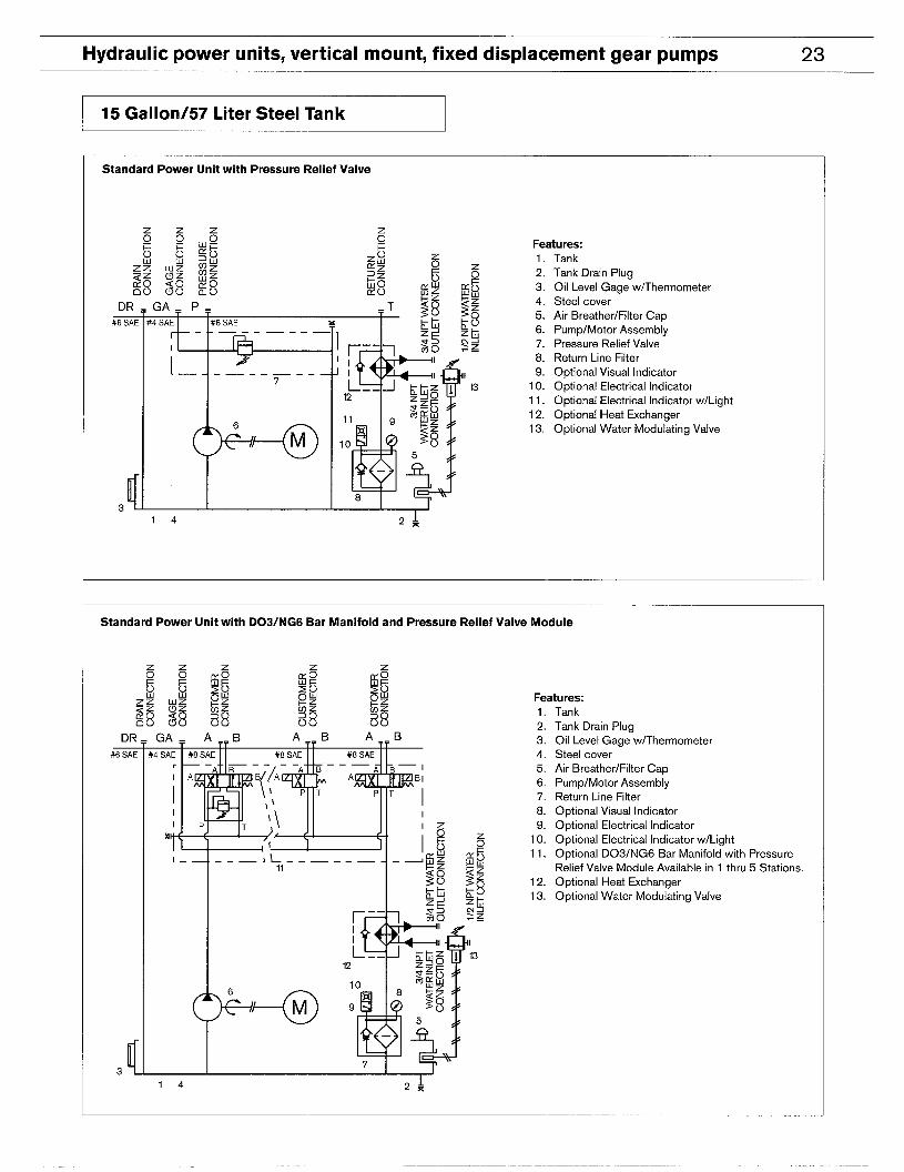
Hydraulic power units, vertical mount, fixed displacement gear pumps 23
15 Gallon/57 Liter Steel Tank
Standard Power Unit with Pressure Relief Valve
z z z zFeatures:1, Tank
5 2. Tank Drain Plug
g 3, Oil Level Gage wiThermometer
4. Steel cover
~5. Air Breather/Filter Cap
6. Pump/Motor Assembly
~ 7. Pressure Relief Valve
8. Return Line Filter
9. Optional Visual Indicator
13 10. Optional Electrical Indicator
11. Optional Electrical Indicator w/Light
12. Optional Heat Exchanger
13. Optional Water Modulating Valve
Standard Power Unit with D03/NG6 Bar Manifold and Pressure Relief Valve Module
66~~g~
KGUIF
w~
Zo g~gl+ Features:
~g j$ ~g Oz58 %
1, Tank
2, Tank Drain PlugDR. GA. A.. B A_. B .-BA 3, Oil Level Gage w/Thermometer
4, Steel cover
5. Air Breather/Filter Cap
6. Pump/Motor Assembly
7, Return Line Filter
8. optional Visual Indicator9. Optional Electrical Indicator
10. Optional Electrical Indicator w/Light
11. Optional D03/NG6 Bar Manifold with Pressure
Relief Valve Module Available in 1 thru 5 Stations.
12. Optional Heat Exchanger
13. Optional Water Modulating Valve

24 Hydraulic power units, vertical mount, fixed displacement gear pumps
15 GaIlon/57 Liter Steel Tank
Standard Power Unit with Pressure Relief Valve Inches (Millimeters)
T#12 SAE REIURN
CONNECTION
OPT.WATER DRMODULATING 37° FLARE
:8 SAE RETURN
VALVE1/2 NW CONNECTION
\
WATER IN OPT. HEATCONNECllON EXCHANGER
3/4 NPT. WATER OUT 2.750
CONNECTION (69.85)
o 0 !I—
o
REIURN
P/’/ c
.
LINE
kti ‘
aFILTER
— —+—-—— -—
PRESSUREREUEFVALVE . .
@
c
r12.000
(304.80)
I
II“k0.500(12.70)DAMTG. HOLE (4 PL4CES)
!==%==!’’’O’O)(457.20)
o I o bI I
J#8 SAE
PRESSURECONNECTION
AR BRE4THER J& FILLERCAP
tlGA
#4 SWG4GEI
a3wEcrm
1 P
/ k

Hydraulic power units, vertical mount, fixed displacement gear pumps 25
I 15 Gallon/57 Liter Steel Tank
Standard Power Unit with D03/NG6 Bar Manifold and Pressure Relief Valve Module Inches (Millimeters)
OPT,WATER DRMODULATING 37’ FLARE OPT. HEATEXCH.
3/4 NPTWATEROUTCONNECTION
i2.750
(69,85)
o_ o 0 t
‘“@P “0
\, 1
I W I
23,750(603.25)25.063(636.60)26.438(671 ,53)28.063(71 2.80)28.613(713,85)30.750(781 ,05)
32.500(825.50)
k=3!!==!t-’i”0’(457.20)
I=d I \
I
I+—–— Ell—iJ-@0
AIR BREATHERJ& FILLERCAP
—
D03/NG6BARMANIFOLD
AND PRES8UREREUEFVALVE
MODULE
12.000(304.80)
(736,60)

26 Hydraulic power units, vertical mount, fixed displacement gear pumps
25 Gallon/95 Liter Steel Tank Specifying/Ordering Procedure : See page 4,
Selection Chart/Ordering Part Numbers
Tank
Volume
Gallon
(Liter)
25
(95)
Pump
Displacement
In’/Rev
(cm’/Rev)
Flow
@l 750 RPM
GPM
(L/rein)
7.41
(28.05)
Power Unit with
Pressure Relief Valw
Par-t Number
Power Unit with Bar
Manifold (D03/NG6)
w/Relief Vlv. Module
Motor
HP
Pressure Max @ HP
Psi
350
550
950
1450
1950
2900
3625
300
450
800
1200
1650
2450
3045
250
400
700
1050
1400
2100
2610
bar
25
38
66
101
135
201
251
21
32
56
83
114
170
211
18
28
49
73
97
145
181
Part Number
9815230315.98
(1 6.0)
2
3
57y2
10
15
20
9815230294
9815230295
9815230296
9815230297
9815230298
9815230299
9815230300
9815230316
9815230317
9815230318
9815230319
9815230320
9815230321
8.78
(33.23)
1.16
(1 9.0)
2
3
57y2
10
15
20
9815230301
9815230302
9815230303
9815230304
9815230305
9815230306
9815230307
9815230322
9815230323
9815230324
9815230325
9815230326
9815230327
9815230328
10,37
(39.25)
1.37
(22.5)
2
3
57%
10
15
20
9815230308
9815230309
9815230310
9815230311
9815230312
9815230313
9815230314
9815230329
9815230330
9815230331
9815230332
9815230333
9815230334
9815230335
Select Accessories
below, if desired.
Select Bar Manifold
below,
Select Accessories
below. if desired.
Standard Power Unita Include:Tank with Drain Plus Return Line Filter
Oil Level Gage with-Thermometer Pressure Relief BlockAir Breather;tiller Cap Drain Connection (DR)Pump/ Motor Assembly Pressure Gage Connection (GA)
All Units are Completely Assembled, Tested and Painted.
I Bar Manifold Selection Chart II Manifold Type I Reference I Description I Par-1Number
Bar Manifold See page 31. 1 Valve Station with Relief Valve Module
(D03/NG6) 2 Valve Stations with Relief Valve Module
3 Valve Stations with Relief Valve Module
4 Valve Stations with Relief Valve Module
5 Valve Stations with Relief Valve Module
98152301019815230102981523010398152301049815230105
Directional Control Valves See page 31. See Basch Catalog “Directional Control Valve D03° Select from catalog.
I Modular Valves I See page 31. I For Check, Reducing, Flow Control and Relief Valves,
1
Select from catalog,
see Bosch Catalog “Madular Valves DO-3 (NG-6)”
Accessory Selection Chart
r Reference Description
Visual (Gage)
Electrical (Pressure Switch) 250 VAC
Electrical with Light (DIN Plug with Light 24 Volt DC)
Electrical with Light (DIN Plug with Light 115 Volt AC)
=
Part Number
9815230106
9815230107
9815230108
9815230109
9815230110
9815230111b Electrical with Light (DIN Plug with Light 230 Volt AC)
See Daae 30. Water to Oil 10 RB5-30
I Water Valve I See page 30. I Modulating Valve w/Bulbwell 1/2 RB5-45-B I 9815230112 I

Hydraulic power units, vertical mount, fixed displacement gear pumps 27
25 Gallon/95 Liter Steel Tank
Standard Power Unit with Pressure Relief Valve
z z z zFeatures:1. Tank
5 2. Tank Drain Plug
~ 3. Oil Level Gage w/Thermometer
z 4. Steel cover
85. Air Breather/Filter Cap
$6. Pump/Motor Assembly
7. Pressure Relief Valve—8, Return Line Filter
9. Optional Visual Indicator
n 10. Optional Electrical Indicator
11, Optional Electrical Indicator w/Light
12. Optional Heat Exchanger
13. Optional Water Modulating Valve
Standard Power Unit with D03/NG6 Bar Manifold and Pressure Relief Valve Module
56~~g~
CK6WF
~$
~g20Oy Features:
g~ $5 ~g (J3Z &z
58 381, Tank
2, Tank Drain PlugDR. GA. A.. B A B .-BA-- 3, Oil Level Gage w/Thermometer
4, Steel cover
5. Air Breather/Filter Cap
6, Pump/Motor Assembly
7, Return Line Filter
8, Optional Visual Indicator
9, Optional Electrical Indicator
10, Optional Electrical Indicator w/Light
11, Optional D03/NG6 Bar Manifold with Pressure
Relief Valve Module Available in 1 thru 5 Stations.
12. Optional Heat Exchanger
13. Optional Water Modulating Valve

28 Hydraulic power units, vertical mount, fixed displacement gear pumps
25 Gallon/95 Liter Steel Tank
Standard Power Unit with Pressure Relief Valve Inches (Millimeters)
------ t------,
I2HP = 27,750
(704.85)
l!3HP = 29,063
(738.20)
5HP = 30,438
‘..~~(773.13)
i7-1 /2HP = 32,063
(814.40)
)-) I IOHP= 32813(833.45)
15HP = 34,750(882.85)
P“ rJ 20HP = 36500u
. (927.10)❑
“❑
.❑
.❑
u
..
.H
u.
.H
.,,
.u
..
.“
.❑
.,
.❑
..
u.
❑❑
,,u..
i
.❑
%
❑
.
. ....
L.=. ==u===... ===. ==...=.=. ..==7..-... . . . . . J
~
0,500 (12.70) D!AMTG, HOLE (4 PLACES)
OPT WATER DR TMODULAllNG 37” PLAREVALVE1/2 NPT (#8) DRAIN
#6 SAE RETURNCONNECTION
T )#16 SAE RETURN
CONNECTION
RETuRNLINE
HLTER
PRESSUREREUEFVALVE
o I o $5/ I
j AIRBREATHERJ& ilL.ER CAP
#8 SAEPRESSURE
CONNECTION
GA#4 S4EG4EE03tU4ECTD’J
7 in
\ I
1r ( I
( t
16.000(406.40)
C,l -J-.----J-*--V,1
---- L +.,------------- +.,-!t,, !. -------------, ,.!
--:---iJ;---\;--L.\
~ 2901JIJ ~(736.60)

Hydraulic power units, vertical mount, fixed displacement gear pumps 29
25 Gallon/95 Liter Steel Tank
Standard Power Unit with D03/NG6 Bar Manifold and Pressure Relief Valve Module Inches (Millimeters)
RETURNUNE
FILTER
Do3iNG6BARMANIFOLD
AND PRESSUREREUEFVALVE
MODULE
3HP = 29063(738.20)
5HP = 30438(773.13)
1/2HP = 32063(81 4.40)
10HP = 32,813(833.45)
15HP = 34,750(882.65)
20HP = ~:2;0100)
\ I I
r16.000
(406.40)
1
0.375(9.53) jL

30 Hydraulic power units, vertical mount, fixed displacement gear pumps
Heat Exchanger
Water to Oil with Built In By-Pass Valve
Performance Characteristics
The curve shown is based onDZ
cooling water at 85° F (28° C) y 20and oil leaving the cooler at 125°
F(52° C). Curve performance isg 15
based on oil with a viscosity of
100 SUS (21 cSt) at 100° Fo 10
(38”C). Pressure drop= 5 PSI at~
20 GPM, n896
Specifications o■ Pressure Rating – 54Maximum working pressure:
Oil side -550 PSI (38 bar),rY3
Water side -220 PSI (15 bar)O_I
■ Temperature Rating –
Maximum working 2 34579 15 20 30 40 50 70temperature: 350° F (1 75° C)
■ Oil to Water Ratio -2:1 OIL FLOW - GPM
@
r-
L-
Water Modulating Valve with Bulbwell
Specifications
■ Standard valve mounting
is on water inlet.
■ Pressure Rating – Maximum
recommended pressure is 125
PSI (8.6 bar).
■ Adjustment Range – This
valve can be adjusted to open
within a range of 60° F to 140°
F (18° Cto 60° C).
■ Temperature Adjustment –
To adjust for lower temperature,
turn adjusting cup counter- 1
clockwise. To adjust for higher
temperature, turn adjustment
cup clockwise. (1/4 turn = 5° F)
■ Modulation Range –\\
This valve is normally closed. A
\@/+ ti~~
MTG, HOLE (4 FfACES)
~~”j) ~93~$jcj~j=]
(76.20)
17,000(431 .60)18.000
(457.20) (736.60)

Hydraulic power units, vertical mount, fixed displacement gear pumps 31
Bar Manifold D03/NG6
u3.00(76,20)
0.62
n
0.62(15,75) (15.75)
I I I
Inches (Millimeters)
,
Q/ OPTIONALGAGE4.50
(114.30)
rI I
I
STATION“ ‘~~5
@ (@~mSTA:ION
1
STATION4
I
1STATION
3J
I
STATION
2 I!Z!!!Z!!!1
I
STATION
I rim
2.13
1 0 (54.10)TYPICAL
I 1 , I
1- 5.08(129,03)
1OPllONAL LIGHT 0.47
(11 .94)
~(l,,J“60’0’J,5■ Any combination of single Note: When ordering valves as part of a bar manifold, please
or double solenoid directional specify the part number(s) ~ the station to which they are to
control valves may be used. be mounted. Stations are identified as in above drawing.
Refer to Bosch catalog
“Directional Control Valve
D03 (NG6).”
■ All modular valves may be
used. Refer to Bosch catalog
“Modular Valves D03 (NG6).”

ROBERT BOSCH FLUID POWER CORPORATIONP.O. BOX 2025RACINE, WISCONSIN 53401-2025 U.S.A.Phone (414)554-7100, Fax (414)554-7117
PRINTED IN U.S.A.
9 535 233 102HPUS AKY 004/3 US (8.93)