HYDRAULIC MOTORS OP
21
HYDRAULIC MOTORS OP Pressure Losses 12 APPLICATION » » » » » » » Conveyors; Feeding mechanism of robots and manipulators; Metal working machines; Textile machines; Machines for agriculture; Food industries; etc. Grass cutting machinery Specification data .............OP-02÷04 Function diagrams ..............OP-05÷09 Dimensions and mounting ........ OP-10 Wheel motor ............................ OP-11 Shaft extensions ........................ OP-12 Permissible shaft loads .............. OP-13 Order code .............................. OP-17 CONTENTS OPTIONS 30 25 20 15 10 5 0 0 10 20 30 40 50 60 70 80 Q l/min p bar 25÷623,6 1600÷95 3,3÷50 3,3÷10,5 140÷55 40÷60 10 Mineral based- HLP(DIN 51524) or HM(ISO 6743/4) -30÷90 20÷75 ISO code 20/16 (Min. recommended fluid filtration of 25 micron) GENERAL 100 140 Pressure drop (bar) Viscosity (mm /s) 2 Oil flow in drain line (l/min) 20 35 20 35 2,5 1,8 3,5 2,8 Oil flow in drain line » » » » » » » » Model- Spool valve, gerotor; Flange and wheel mount; Motor with needle bearing Side and rear ports; Shafts- straight, splined and tapered; Shaft seal for high and low pressure; Metric and BSPP ports; Other special features. Displacement, Max. Speed, Max. Torque, Max. Output, Max. Pressure Drop, Max. Oil Flow, Min. Speed, Pressure fluid Temperature range, Optimal Viscosity range, Filtration [cm /rev.] [RPM] [daNm] [kW] [bar] [l/min] [RPM] [C] [mm /s] 3 O 2
Transcript of HYDRAULIC MOTORS OP

HYDRAULIC MOTORS OP
Pressure Losses
12
APPLICATION»
»
»
»
»
»
»
Conveyors;Feeding mechanism of robots and manipulators;Metal working machines;Textile machines;Machines for agriculture;Food industries;
etc.Grass cutting machinery
Specification data .............OP-02÷04
Function diagrams ..............OP-05÷09
Dimensions and mounting ........ OP-10
Wheel motor ............................ OP-11
Shaft extensions ........................ OP-12
Permissible shaft loads .............. OP-13
Order code .............................. OP-17
CONTENTS OPTIONS
30
25
20
15
10
5
0
0 10 20 30 40 50 60 70 80 Q l/min
pbar
25÷623,6
1600÷95
3,3÷50
3,3÷10,5
140÷55
40÷60
10
Mineral based- HLP(DIN 51524) or HM(ISO 6743/4)
-30÷90
20÷75
ISO code 20/16 (Min. recommended fluid filtration of 25 micron)
GENERAL
100
140
Pressure drop(bar)
Viscosity(mm /s)2
Oil flow indrain line
(l/min)20
35
20
35
2,5
1,8
3,5
2,8
Oil flow in drain line
»
»
»
»
»
»
»
»
Model- Spool valve, gerotor;Flange and wheel mount;Motor with needle bearingSide and rear ports;Shafts- straight, splined and tapered;Shaft seal for high and low pressure;Metric and BSPP ports;Other special features.
Displacement,
Max. Speed,
Max. Torque,
Max. Output,
Max. Pressure Drop,
Max. Oil Flow,
Min. Speed,
Pressure fluid
Temperature range,
Optimal Viscosity range,
Filtration
[cm /rev.]
[RPM]
[daNm]
[kW]
[bar]
[l/min]
[RPM]
[ C ]
[mm /s]
3
O
2
marina guaitoli
Motors OP - 01

OP OP OP OP(W) OP OP(W) OP OP(W) OP25 32 40 50 50…B… 80 80…B… 100 100…B…
25 32,0 40,0 49,5 49,5 79,2 79,2 99 99
Max. Speed, cont. 1600 1560 1500 1210 1210 755 755 605 605
[RPM] int.* 1800 1720 1750 1515 1515 945 945 755 755
Max. Torque, cont. 3,3 4,3 6,2 9,4 9,4 15,1 15,1 19,3 19,3
[daNm] int.* 4,7 6,1 8,2 11,9 11,9 19,5 19,5 23,7 23,7
peak** 6,7 8,6 10,7 14,3 14,3 22,4 22,4 27,5 27,5
Max. Output, cont. 4,5 5,8 8,4 10,1 10,1 10,2 10,2 10,5 10,5
[kW] int.* 6,1 7,8 11,6 12,2 12,2 12,5 12,5 12,8 12,8
Max. Pressure cont. 100 100 120 140 140 140 140 140 140
Drop, int.* 140 140 155 175 175 175 175 175 175
[bar] peak** 225 225 225 225 225 225 225 225 225
Max. Oil Flow, cont. 40 50 60 60 60 60 60 60 60
[lpm] int.* 45 55 70 75 75 75 75 75 75
Max. Inlet cont. 175 175 175 175 175 175 175 175 175
Pressure, int.* 200 200 200 200 200 200 200 200 200
[bar] peak** 225 225 225 225 225 225 225 225 225
Max. Return cont. 0-100 RPM 150 150 150 150 100 150 100 150 100
Pressure w/o cont. 100-300 RPM 75 75 75 75 30 75 30 75 30
Drain Line or cont. 300-600 RPM 50 50 50 50 15 50 15 50 15
Max. Pressure in cont. >600 RPM 20 20 20 20 - 20 - 20 -
Drain Line, [bar] int.* 0-max RPM 150 150 150 150 100 150 100 150 100
Max. Return cont. 175 175 175 175 175 175 175 175 175
Pressure with int.* 200 200 200 200 200 200 200 200 200
Drain Line, [bar] peak** 225 225 225 225 225 225 225 225 225
10 10 10 10 10 10 10 10 10
Min. Starting Torque at max. press. drop cont. 3 4 5.4 7,8 7,8 13,2 13,2 16,6 16,6
[daNm] at max. press. drop int.* 4.2 5,6 6.9 10 10 16,8 16,8 21 21
Min. Speed [RPM] 20 15 10 10 10 10 10 10 10
OPF 5,6 5,6 5,7 5,8 5,9 6,1OP(F)(E)…B… 5,9 (6,4) 6 (6,5) 6,2 (6,7)OPQ(N) 5,2 5,3 5,5
OP(F)(N)E 6,3 6,4 6,6
OPW(N) 5,5 5,6 5,8
OPQ(N)E 5,7 5,8 6,0
Weight [kg]
Type
Displacement [cm3/rev.]
Max. Starting Pressure with Unloaded Shaft [bar]
* Intermittent operation: the permissible values may occur for max. 10% of every minute.** Peak load: the permissible values may occur for max. 1% of every minute.*** For speeds of 10 RPM or lower, consult factory or your regional manager.1. Intermittent speed and intermittent pressure drop must not occur simultaneously.2. Recommended filtration is per ISO cleanliness code 20/16. A nominal filtration of 25 micron or better.3. Recommended using a premium quality, anti-wear type mineral based hydraulic oil
4. Recommended minimum oil viscosity 13 mm²/s at operating temperatures.5. Recommended maximum system operating temperature is 82 C.6. To assure optimum motor life fill with fluid prior to loading and run at moderate load and speed for 10-15 minutes.
HLP(DIN51524) or HM (ISO 6743/4).If using synthetic fluids consult the factory for alternative seal materials.
0
13
SPECIFICATION DATA
Motors OP - 02

SPECIFICATION DATA (continued)
T y p e OP 125 OP OP 160 OP OP 200 OP OPW 125 125...B... OPW 160 160...B... OPW 200 200...B...
158,4
378
472
31,3
37,8
43,8
10,1
12,1
140
175
225
60
75
175
200
225
150
75
50
-
150
175
200
225
8
28,2
35,5
10
6,4
5,8
6,9
6,1
6,3
158,4
378
472
31,3
37,8
43,8
10,1
12,1
140
175
225
60
75
175
200
225
100
30
15
-
100
175
200
225
8
28,2
35,5
10
6,5(6,9)
198
303
378
36,6
45,6
55
10
12
140
175
225
60
75
175
200
225
150
75
50
-
150
175
200
225
7
33,5
42,6
10
6,6
6,0
7,1
6,3
6,5
198
303
378
36,6
45,6
55
10
12
140
175
225
60
75
175
200
225
100
30
15
-
100
175
200
225
7
33,5
42,6
10
6,7(7,2)
123,8
486
605
23,7
29,8
36,5
10
12
140
175
225
60
75
175
200
225
150
75
50
-
150
175
200
225
9
20,7
26,6
10
6,2
5,6
6,7
5,9
6,1
123,8
486
605
23,7
29,8
36,5
10
12
140
175
225
60
75
175
200
225
100
30
15
-
100
175
200
225
9
20,7
26,6
10
6,3(6,8)
Displacement, [cm /rev.]Max. Speed,[RPM]Max.Torque[daNm]Max. Output,[kW]Max. PressureDrop[bar]Max. Oil Flow[l/min]Max. InletPressure[bar]Max. Return Pressurew/o Drain Line orMax. Pressure inDrain Line,[bar]Max. Return Pressurewith Drain Line[bar]Max. Starting Pressure with Unloaded Shaft, [bar]Min. Starting Torque[daNm]Min. Speed***, [RPM]Weight, avg. [kg]
3
cont.int.*cont.int.*peak**cont.int.*cont.int.*peak**cont.int.*cont.int.*peak**cont. 0-100 RPMcont. 100-300 RPMcont. 300-600 RPMcont. >600 RPMint.* 0-max. RPMcont.int.*peak**
at max. press drop cont.at max. press. drop int.*
OPFOP(F)(E)...OPQ(N)OP(F)(N)EOPW(N)OPQ(N)E
B...
* Intermittent operation: the permissible values may occur for max. 10% of every minute.** Peak load: the permissible values may occur for max. 1% of every minute.*** For speeds of 10 RPM or lower, consult factory or your regional manager.1. Intermittent speed and intermittent pressure drop must not occur simultaneously.2. Recommended filtration is per ISO cleanliness code 20/16. A nominal filtration of 25 micron or better.3. Recommended using a premium quality, anti-wear type mineral based hydraulic oil
4. Recommended minimum oil viscosity 13 mm²/s at operating temperatures.5. Recommended maximum system operating temperature is 82 C.6. To assure optimum motor life fill with fluid prior to loading and run at moderate load and speed for 10-15 minutes.
HLP(DIN51524) or HM (ISO 6743/4).If using synthetic fluids consult the factory for alternative seal materials.
0
marina guaitoli
Motors OP - 03

SPECIFICATION DATA (continued)
T y p e 250 250...B... 315 315...B... 400 400...B... 500 630OP(W) OP OP(W) OP OP(W) OP OP OP
247,5
242
303
38
58,3
68,5
7,5
12
110
175
225
60
75
175
200
225
150
75
-
-
150
175
200
225
6
33,6
54,2
10
6,8
6,2
7,3
6,5
6,7
247,5
242
303
47
58,3
68,5
9,5
12
140
175
225
60
75
175
200
225
100
30
-
-
100
175
200
225
6
42,8
54,2
10
6,9(7,4)
316,8
190
236
38
56
85
5,7
9
90
140
225
60
75
175
200
225
150
75
-
-
150
175
200
225
5
34,4
61,9
10
7,1
6,5
7,6
6,8
7,0
316,8
190
236
48,6
56
85
7,6
9
120
140
225
60
75
175
200
225
100
30
-
-
100
175
200
225
5
45,8
61,9
10
7,2(7,7)
396
150
189
36
59
85,4
4,6
7,8
70
115
180
60
75
175
200
225
150
75
-
-
150
175
200
225
5
34,5
60,8
10
7,6
6,8
8,1
7,2
7,3
396
150
189
50
59
85,4
6,2
7,8
95
115
180
60
75
175
200
225
100
30
-
-
100
175
200
225
5
46,8
60,8
10
7,7(8,2)
495
120
150
39
57
78
3,5
7,2
60
90
130
60
75
140
175
225
150
75
-
-
150
140
175
225
5
36
54
10
8,9
8,3
9,3
8,8
623,6
95
120
44
64
82
3,3
5,6
55
80
110
60
75
140
175
225
150
-
-
-
150
140
175
225
5
41,5
62
10
9,5
9,0
10
8,5
Displacement, [cm /rev.]Max. Speed,[RPM]Max.Torque[daNm]Max. Output,[kW]Max. PressureDrop[bar]Max. Oil Flow[l/min]Max. InletPressure[bar]Max. Return Pressurew/o Drain Line orMax. Pressure inDrain Line,[bar]Max. Return Pressurewith Drain Line[bar]Max. Starting Pressure with UnloadedShaft, [bar]Min. Starting Torque[daNm]Min. Speed***, [RPM]Weight, avg. [kg]
3
cont.int.*cont.int.*peak**cont.int.*cont.int.*peak**cont.int.*cont.int.*peak**cont. 0-100 RPMcont. 100-300 RPMcont. 300-600 RPMcont. >600 RPMint.* 0-max. RPMcont.int.*peak**
at max. press drop cont.at max. press. drop int.*
OPFOP(F)(E)...OPQ(N)OP(F)(N)EOPW(N)OPQ(N)E
B...
* Intermittent operation: the permissible values may occur for max. 10% of every minute.** Peak load: the permissible values may occur for max. 1% of every minute.*** For speeds of 10 RPM or lower, consult factory or your regional manager.1. Intermittent speed and intermittent pressure drop must not occur simultaneously.2. Recommended filtration is per ISO cleanliness code 20/16. A nominal filtration of 25 micron or better.3. Recommended using a premium quality, anti-wear type mineral based hydraulic oil
4. Recommended minimum oil viscosity 13 mm²/s at operating temperatures.5. Recommended maximum system operating temperature is 82 C.6. To assure optimum motor life fill with fluid prior to loading and run at moderate load and speed for 10-15 minutes.
HLP(DIN51524) or HM (ISO 6743/4).If using synthetic fluids consult the factory for alternative seal materials.
0
Motors OP - 04

SPECIFICATION DATA for OP...FR
Type
Max. Starting Pressure withUnloaded Shaft, [bar]
OP 100OP 50 OP 160OP 80 OP 125 OP 200
8 8 8 7,5 6,5 5,5
Look at specification data for hydraulic motors series OP standard version. Only the parameter Starting Pressure ismodified.
version “FR” these are the hydraulic motors with reduced mechanical losses , for wich at disengagedcondition ( unconnected with driving mechanism ) the rotation of the shaft could be realized by means of small torque.This advantage is especially usefull at operating with high frequencies of rotation (over than 300 min ) and low pressuredrop, which is inbred for types with displacements of up to 200 cm3. It is normal for these for the different condition ofoperation to have high torque, as well as high volume losses: the values of the volumetric efficiency are lower (up to 5 %for middle and up to 10 % for high values of the pressure drop), than these of the normal versions. That's why therecommended operatingfor “FR version is for applications with pressure drop up to 100 bar.
Additional advantages of “FR” version are prolonging of the life of the hydraulic motors at high frequencies ofrotation, as well as the possibility to use them in systems with big variation of the loading.
Free Running
-1
OP 25
8
OP 32
8
OP 40
8
Low Speed Valve (LSV) “LSV” Series hydraulic motors have been designed to operate with normal pressure drop and toensure smooth run at low speed (up to 200 RPM), as the best security for operation is guaranteed at frequency of rotation20 ÷ 50 RPM . They have an increased starting pressure drop and are not recommended for using at pressure less than40 bar.Look at specification data for hydraulic motors standard version. The modification concerns only the followingparameters: maximum speed, maximum output,maximum Oil flow and maximum starting pressure.
SPECIFICATION DATA for OP...LSV
Type
Max. Output[kW]Max. Oil Flow[lpm]
Max. Speed[RPM]
Cont.
Int.*
Cont.
Int.*
Cont.
Int.*
OP40
OP32
OP25
OP200
OP50
OP315
OP80
OP250
OP400
200
250
0,7
1,2
9,0
13,5
200
250
0,9
1,5
11,0
16,5
200
250
1,2
2,0
11
14
200
250
2,0
3,2
15
20
200
250
3
5
22
29
200
250
7,0
9,8
40
50
200
250
5,2
9,1
40
50
190
236
4,2
7,2
40
50
150
190
3,4
6,0
40
50
OP500
OP630
80
101
2,9
5,0
40
50
64
80
2,6
4,2
40
50
OP100
200
250
3,8
6,0
24
33
OP125
200
250
4,9
7,2
30
38
OP160
200
250
6,1
9,5
34
46
SPECIFICATION DATA for OP...LL
Type
Max. Output[kW]Max. Pressure Drop[bar]
Max. Torque[daNm]
Min. Starting Torque[daNm]
Cont.
Int.*
Cont.
Int.*
Cont.
Int.*
Cont.
Int.*
OP40
OP32
OP25
OP200
OP50
OP315
OP80
OP250
OP400
3,1
4,3
4,3
6,0
100
140
4,5
6,0
4,1
5,8
5,6
7,7
100
140
5,7
7,0
5,8
7,8
8,2
11,5
120
155
6,8
8,0
9,0
11,3
10
12
140
175
7,4
9,5
14,4
18,5
10,1
12,3
140
175
12,5
16,0
34,8
43,3
9,9
11,8
140
175
31,8
40,5
44,6
55,4
9,4
11,8
140
175
40,7
51,5
46,2
53,2
7,5
8,9
120
140
43,5
58,8
47,5
56,0
6,1
7,7
95
115
44,5
57,8
Look at specification data for hydraulic motors series OP standard version. The modification concerns only theparameters: maximum torque,maximum output, minimum starting torque.
“LL” Series hydraulic motors have been designed to operate at the whole standard range ofworking conditions (pressure drop and frequency of rotation ) , but with considerable decreased volumetric losses in thedrainage ports. Their main purposeis to operateas series-connected motors in hydraulic systems.
For this version is permissible decreasing of the maximal torque with up to 5% (at middle speed) and up to 10%(at high speed) in comparison to the standard versions of motors.
Low Leakage (LL)
OP500
OP630
38
55
3,4
7,1
60
90
46
52
42,8
62,0
3,2
5,5
55
80
50
60
OP100
18,4
22,5
10,4
12,6
140
175
15,8
20,0
OP125
22,5
28,3
9,9
11,8
140
175
19,6
25,2
OP160
29,8
36,0
10
12
140
175
26,8
33,7
25 25 25 20 20 20 20 15 15 15 12 12 10 10Max. Starting Pressure withunloaded Shaft, [bar]
marina guaitoli
Motors OP - 05
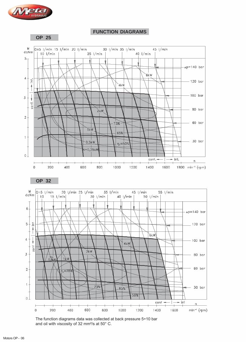
OP 32
OP 25
17
FUNCTION DIAGRAMS
The function diagrams data was collected at back pressure 5÷10 barand oil with viscosity of 32 mm²/s at 50° C.
Motors OP - 06

OP 50
OP 40
18
FUNCTION DIAGRAMS
The function diagrams data was collected at back pressure 5÷10 barand oil with viscosity of 32 mm²/s at 50° C.
marina guaitoli
Motors OP - 07

MOTORS
EPM
OP 100
19
FUNCTION DIAGRAMS
The function diagrams data was collected at back pressure 5÷10 barand oil with viscosity of 32 mm²/s at 50° C.
OP 80
Motors OP - 08

OP 160
20
FUNCTION DIAGRAMS
The function diagrams data was collected at back pressure 5÷10 barand oil with viscosity of 32 mm²/s at 50° C.
OP 125
Motors OP - 09
MOTORS
EPM
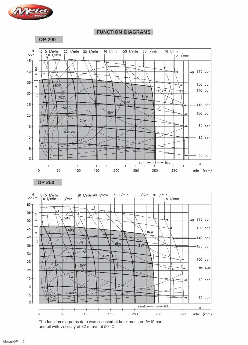
OP 250
21
FUNCTION DIAGRAMS
The function diagrams data was collected at back pressure 5÷10 barand oil with viscosity of 32 mm²/s at 50° C.
OP 200
Motors OP - 10

Motoren
EPMM
OP 400
FUNCTION DIAGRAM
The function diagram data was collected at back pressure 5÷10 barand oil with viscosity of 32 mm²/s at 50° C.
OP 315
MOTORS
EPM
22
Motors OP - 11

OP 630
23
FUNCTION DIAGRAM
The function diagram data was collected at back pressure 5÷10 barand oil with viscosity of 32 mm²/s at 50° C.
OP 500
MOTORS
EPM
100 20 30 5040 60 70 9080 100 110 130120 140 150
n
min (rpm)-1
0
5
10
15
20
25
30
35
40
45
50
55
60
65
70
75
M
daNm
int.
cont.
int.cont.
10 l/min
Q=5 l/min 20 l/min 30 l/min 40 l/min 50 l/min 60 l/min 70 l/min 75 l/min
N=0,5kW80%
75%1kW
2kW
3kW
4kW 5kW
6kW
70%
60%
65% 50%
110 bar
90 bar
75 bar
60 bar
45 bar
30 bar
15 bar
0
5
10
15
20
25
30
35
40
45
50
55
60
65
70
int.
cont.
int.cont.
100 20 30 5040 60 70 9080 100 110 120
n
min (rpm)-1
M
daNm 10 l/min
Q=5 l/min 20 l/min 30 l/min 40 l/min 50 l/min 60 l/min 70 l/min 75 l/min
80 bar
70 bar
55 bar
45 bar
30 bar
15 bar
N=0,5kW80%
75%1kW
2kW
3kW 4kW5kW
70%65%
60%50%
Motors OP - 12

DIMENSIONS AND MOUNTING DATA
MountingPorting
E -RearPorts
Oval Mount (2 Holes)
F - Oval Mount (4 Holes)
Q - Square Mount (4 Bolts)C :P :T :
4xM8-13mm depth2xG1/2 or 2xM22x1,5-15mm depthG1/4 or M14x1,5-12mm depth (plugged)
(A, B)
Side Ports
L,mm L,mm L,mm L,mm L1, mm133,2
134,5
135,2
135,6
139,6
142,2
145,6
150,2
155,6
162,2
171,6
182,2
193,0
210,5
139,4
140,7
141,4
141,8
145,8
148,4
151,8
156,4
161,8
168,4
177,8
188,4
199,0
216,5
151,2
152,5
153,2
155,8
159,8
162,4
165,8
170,4
175,8
182,4
191,8
202,4
213,0
230,5
157,4
158,7
159,4
162,0
166,0
168,6
172,0
176,6
182,0
188,6
198,0
208,6
219,0
236,5
4,60
5,90
7,40
6,67
10,67
13,33
16,67
21,33
26,67
33,33
42,67
53,33
66,63
84,00
TypeOPF 25OPF 32OPF 40OPF 50OPF 80OPF 100OPF 125OPF 160OPF 200OPF 250OPF 315OPF 400OPF 500OPF 630
OP(F)E 25OP(F)E 32OP(F)E 40OP(F)E 50OP(F)E 80OP(F)E 100OP(F)E 125OP(F)E 160OP(F)E 200OP(F)E 250OP(F)E 315OP(F)E 400OP(F)E 500OP(F)E 630
Type Type
OPQ 50OPQ 80OPQ 100OPQ 125OPQ 160OPQ 200OPQ 250OPQ 315OPQ 400OPQ 500OPQ 630
OPQ 25OPQ 32OPQ 40
Type
OPQE 50OPQE 80OPQE 100OPQE 125OPQE 160OPQE 200OPQE 250OPQE 315OPQE 400OPQE 500OPQE 630
OPQE 25OPQE 32OPQE 40
MOTORS
EPM
55±0,1
2x 13,52x 13,5
55±0,1
min 15 deepmin 15 deep
max Lmax L
4x 13,54x 13,5
55±0,1Port A
Port B
Standard RotationViewed from Shaft EndPort A Pressurized - CWPort B Pressurized - CCW
Reverse RotationViewed from Shaft End
Port B Pressurized - CWPort A Pressurized - CCW
Port A
Port B
106,4±0,2
ø106,4±0,2
marina guaitoli
Motors OP - 11

DIMENSIONS AND MOUNTING DATA - OPW
P :T :
(A, B)2xG1/2 or 2xM22x1,5 - 15 mm depthG1/4 or M14x1,5 - 12 mm depth (plugged)
W - Wheel Mount
L, mm L , mm1
76,5
78,0
79,5
82,0
85,0
88,0
93,0
98,0
105,0
114,0
125,0
78,0
4,6
5,9
7,4
6,67
10,67
13,33
16,67
21,33
26,67
33,33
42,67
53,33
Type
OPW(N) 25OPW(N) 32OPW(N) 40OPW(N) 50OPW(N) 80OPW(N) 100OPW(N) 125OPW(N) 160OPW(N) 200OPW(N) 250OPW(N) 315OPW(N) 400
MOTORS
EPM
Standard RotationViewed from Shaft EndPort A Pressurized - CWPort B Pressurized - CCW
Reverse RotationViewed from Shaft End
Port B Pressurized - CWPort A Pressurized - CCW
max 105max 105
ø103±0,1
55±0,1
max100
max100
maxL
maxL
min
20
T
P(A,B)P(A,B)
Port A Port B
1: Max. radial shaft load2: n=300 min3: n=500 min4: n=800 min
-1
-1
-1
PERMISSIBLE SHAFT LOADS
OPW
1: Max. radial shaft load2: n= 50 min3: n=200 min4: n=800 min
-1
-1
-1
P
daNrad
0
200
400
600
800
1000
1200
1400
1600
0 20 40 60 80 100 mm112,4
Pa =150 daNmax
Pa =200 daNmax
4
3
2
1
P
daNrad
Pa =150 daNmax
Pa =200 daNmax
00 20 40 60 80 100 112,4 mm
200
400
600
800
1000
1200
1400
1600
4
3
21
The curves apply to a B10 bearing life of 2000 hours.
OPWN
Motors OP - 12

26
SHAFT EXTENSIONS FOR OP AND OR MOTORSMOTORS
CB ø32 straight, Parallel key A10x8x45 DIN 6885Max. Torque 77 daNm
-
SB - splined A25x22xH10 DIN 5482Max. Torque 44 daNm
KB - tapered 1:10, key B6x6x20 DIN 6885Max. Torque 77 daNm
Parallel
C ø25 straight, key A8x7x32 DIN 6885Max. Torque 44 daNm
- Parallel
CO ø1" straight, key ¼"x¼"x1¼" BS46Max. Torque 44 daNm
- Parallel
SH - splined, BS 2059 (SAE 6B)Max. Torque 44 daNm
K tapered 1:10, key B5x5x14 DIN 6885Max. Torque 40 daNm
- Parallel
SA splined, B25x22h9 DIN 5482Max. Torque 40 daNm
-
�- Motor Mounting Surface
HB splined , ANSI B92.1-1976 NormMax. Torque 77 daNm
- ø1¼" 14T
OB tapered 1:8 , key "x "x1¼" BS46Max. Torque 77 daNm
- SAEJ 501 Parallel 5
16
5
16
ø25±0,210
ø22±0,130
ø25,32±0,03
min 26,4min 26,4
M8
min16 Deep
M8
min16 Deep
43,2±0,5
M8
min16 Deep
M8
min16 Deep
43,2±0,5
M8
min16 Deep
M8
min16 Deep 56,5+0,4-1,0+0,4-1,0
43,2±0,5M8
min16 Deep
M8
min16 Deep
56,5+0,4-1,0+0,4-1,0
35±0,6
ø4
5±0,255±0,25
S=1 / "
Tightening Torque
20±1 daNm
716
56,5+0,4-1,0+0,4-1,0
M8
min16 Deep
M8
min16 Deep
58±0,458±0,4
36±0,7
ø4,5±0,1ø4,5±0,1
5±0,25
ø35±0,01
S=41Tightening Torque
20±1 daNm
S=30Tightening Torque
10±1 daNmø4,5±0,1
5±0,25
ø28,56±0,01
43,2±0,5M8
min16 Deep
M8
min16 Deep
marina guaitoli
Motors OP - 13

27
PERMISSIBLE SHAFT LOADS FOR OP MOTORS
The permissible radial shaft load P depends on the speed (RPM) and distance (L) from the point of loadto the mounting flange.
rad
Radial Shaft Load P for Shaft Extensions
by L=30 (24) mmrad C, CO
MOTORS
Mounting Flange
Shaft Version cylindrical - C, COtapered - K, splined - SH
cylindrical - C, COsplined - HBcylindrical - CB
Radial Shaft Load Pradx , daN800
n2500095+L
x , daN800n
1875095+L
x , daN800n
25000101+L
*
1: Max. radial shaft load2: n= 50 min3: n=200 min4: n=800 min
-1
-1
-1
n<200 min ; max P =800 daN-1rad
*n>200 min ; L<55 mm-1_
Prad
daN
Pa =150 daNmax
Pa =200 daNmax
Oval Mount
Square Mount
Prad
The curves apply to a B10 bearing life of 2000 hours.
OPN
P
daNrad
0
200
400
600
800
1000
1200
1400
1600
020406080 mm-20 -40
Pa =150 daNmax
Pa =200 daNmax
OP
4
3
21
Motors OP - 14

Meta Hydraulic is introducing hydraulic motor with a new generation of speed sensor. The electric output
signal is a standard voltage signal that can be used for regulating the speed of a motor.
The speed is measured by a sensor in accordance with the Hall principle. Signal processing and
amplification are performed in the sensor housing.Aconnection is provided in the housing by a Plug connector
M12 Series.
HYDRAULIC MOTORS WITH SPEED SENSOR TYPE OP...RS
This performance is applicable for all motors of OP and OR series. The main technical features
correspond to the standard motors series OP and OR.
For detail technical and mounting data please refer to Meta catalogue.
OP...RS
Hall sensor
marina guaitoli
Motors OP - 15
Giordano Benassi

U
ff1f2
U >U -2Vhigh d.c.
U <2Vlow
Output signal
DIFFERENTIAL HALL SENSOR
Load max.:I =I <50mAhigh low
No load current, max: 20 mA
Wiring diagram
1
4
3 min. R =U /I (=50 mA)L d. c. m ax.PNP
+Ud.c.
-Ud.c.
Stik type
1 2
34 Terminal No. Connection
1
2
3
4
U (+supply)d. c.
No connection
U (-supply)d. c.
Output signal
Technical data
Frequency rangeOutputPower supplyCurrent inputCurrent loadAmbient TemperatureProtectionPlug connectorMounting principle
3...20 000 HzPNP10...36 VDC20 mA (@24 VDC)500 mA (@24 VDC;24 C)minus 40... plus 125 CIP 67M12-SeriesISO 6149
0
0
f =f±10%1
Motors OP - 16

C
VC
CO
VCO
-
-
-
-
ø25 straight, Parallel key A8x7x32 DIN6885ø25 straight, Parallel key A8x7x32 DIN6885with corrosion resistant bushingø1" straight, Parallel key ¼"x¼"x1¼" BS46ø1" straight, Parallel key ¼"x¼"x1¼" BS46with corrosion resistant bushing
omit - none-Low Leakage- Low Speed Valve- Free Running
LL
LSV
FR
M
omit - BSPP (ISO 228)- Metric (ISO 262)
O P
Pos.3 - Mounting Flange
Pos. 9 - Special Features (see Specification data on page OP - 05)
Pos.10 - Rotation
Pos.11 - (Paint)***Option
Pos.12 -
Pos.4 - (needle bearings)Option
Pos.5 - Port type
Pos.6 - Displacement codePos. 8 - Ports
omit - Standard Rotation- Reverse RotationR
omit - no Paint- Painted- Corrosion Protected Paint
P
PC
omit - none- needle bearingsN* with
omit - Side ports- Rear portsE
Pos. 7 - Shaft Extensions**(see page OP - 13)
omit - Oval mount- Oval mount- S
, two holes, four holes
quare mount, four bolts- Wheel mount
F
Q
W
SH
VSH
K
SA
VSA
HB
- ø25,32 splined BS 2059 (SAE 6B)- ø25,32 splined BS 2059 (SAE 6B)with corrosion resistant bushing
-- ø24,5 splined B 25x22 DIN 5482- ø24,5 splined B 25x22 DIN 5482
with corrosion resistant bushingø32 straight, Parallel key A10x8x45 DIN6885ø35 tapered 1:10, Parallel key B6x6x20 DIN6885splined A 25x22 DIN 5482ø1¼" tapered1:8, Parallel key "x "x1¼" BS46
- ø1¼" splined 14T ANSI B92.1 - 1976
CB
KB
SB
OB
ø28,56 tapered 1:10, Parallel key B5x5x14 DIN6885
-
-
-
-
25*
32*
40*
50
80
100
125
160
200
250
315
400
500
630
- 25,0 [cm /rev]- 32,0 [cm /rev]- 40,0 [cm /rev]- 49,5 [cm /rev]- 79,2 [cm /rev]- 99,0 [cm /rev]- 123,8 [cm /rev]- 158,4 [cm /rev]- 198,0 [cm /rev]- 247,5 [cm /rev]- 316,8 [cm /rev]- 396,0 [cm /rev]- 495,0 [cm /rev]- 623,6 [cm /rev]
3
3
3
3
3
3
3
3
3
3
3
3
3
3
Uomit - with drain port
- without drain port
Pos.2 - Case DrainDomit - Low pressure seal or Seal for "...B" shaft
- High pressure seal not for "...B" shaft
Pos.1 - Shaft Seal Version (see page OR-10)
ORDER CODE
1 2 3 4 5 6 7 8 9 10 11 12
NOTES:D
Q, W, N “...B”
* Only with " " Shaft Seal Versions!** The permissible output torque for shafts must be not exceeded!
The following combinations are not allowed- options with shafts.***Color at customer's request.
The hydraulic motors are mangano-phosphatized as standard.
Speed Monitoringomit - none
- with speed sensor (PNP pull-down resistor)
- with speed sensor (NPN pull-up resistor)
RS-P
RS-N
marina guaitoli
Motors OP - 17

SPECIFICATION DATA
* Intermittent operation: the permissible values may occur for max. 10% of every minute.
OP50/NA OP80/NAOP100/NAOP125/NAOP160/NAOP200/NAOP250/NAOP315/NAOP400/NA
49,5
79,2
99,0
123,8
158,4
198,0
247,5
316,8
396,0
Displa-cement
[cm /rev]3
Max.Speed[RPM]
Max. Torque[daNm]
Max. PressureDrop[bar]
Max. OilFlow[lpm]
cont. cont. cont.
Code
int* int* cont.
Max. Output[kW]
cont. int*
200
200
200
200
200
200
200
190
15
9,4
15,1
19,3
23,7
26,4
30,0
33,0
34,7
33,5
11,9
19,5
23,7
29,8
37,8
36,5
40,5
40,2
41,0
1,5
2,5
4,0
5,0
4,5
5,0
5,5
5,5
4,5
2,0
3,0
4,5
5,5
5,5
6,5
6,0
6,0
6,0
140
140
140
140
120
115
100
85
65
175
175
175
175
175
140
125
100
80
10
16
20
25
32
40
50
60
60
Meta Hydraulic presents the new hydraulic motor OP.../NA, which is modification of thehydraulic motor type OP. Dimension and pressure range are same as OP hydraulicmotor.
OP.../NA is suitable for driven mechanism where is demand smooth operation low speedand high pressure. It is designed with separated output shaft and spool valve and can bespecified with low internal leakage, thereby:
A
B
�
�
�
�
Good start-up characteristics;Precise control of the Torque at low small flow.Smooth operation at high pressure and small oil flow;High volumetric efficiency.
�
�
�
Actuator motor as driving-motor forsteering mechanism of the the three-wheel vehicles;
For conveyors (series connection);
Dosing motor etc.
INTRODUCTION
APPLICATION T L
RP
HydraulicReservoir
LOW SPEED HIGH TORQUE MOTORS OP.../NA
Motors OP.../NA - 01

O P1 2 3 4 5 6
Pos.1 - Displacement code50
80
100
125
160
200
250
315
400
- 49,5 [cm /rev]- 79,2 [cm /rev]- 99,0 [cm /rev]- 123,8 [cm /rev]- 158,4 [cm /rev]- 198,0 [cm /rev]- 247,5 [cm /rev]- 316,8 [cm /rev]- 398,0 [cm /rev]
3
3
3
3
3
3
3
3
3
C
CO
-
-
ø25 straight, Parallel key A8x7x32 DIN6885ø1" straight, Parallel key ¼"x¼"x1¼" BS46
- ø28,32 splined BS 2059 (SAE 6B)-
ø24,5 splined B25x22h9 DIN 5482
SH
K ø28,56 tapered 1:10, Parallel key,B5x5x14 DIN6885
-SA
Pos.2 - Shaft Extensions*
Pos. 4 - Rotation
Pos. 5 - (Paint)**Option
Pos. 6 - Design Series
omit - Standard Rotation- Reverse RotationR
omit - no Paint- Painted- Corrosion Protected Paint
P
PC
NA - Low speed, high pressure
M
omit - BSPP (ISO 228)- Metric (ISO 262)
Pos. 3 - Ports
ORDER CODE
NOTES:* The permissible output torque for shafts must be not exceeded!** Color at customer's request.
The hydraulic motors are mangano phosphatized as standard.
NA
marina guaitoli
Motors OP.../NA - 02