HYDRAULIC MOTORS - Niehues · HYDRAULIC MOTOR SAFETY PRECAUTION A hydraulic motor must not be used...
92
HYDRAULIC MOTORS Medium Duty Series Delivering The Power To Get Work Done HYDRAULIC MOTORS LD | MD | HD HYDRAULIC MOTOR | BRAKE UNITS STEERING UNITS HYDRAULIC BRAKES HYDRAULIC PUMPS FLOW DIVIDERS
Transcript of HYDRAULIC MOTORS - Niehues · HYDRAULIC MOTOR SAFETY PRECAUTION A hydraulic motor must not be used...
HYDRAULIC MOTORSMedium Duty Series
Delivering The Power To Get Work Done
HYDRAULIC MOTORS
LD | MD | HD
HYDRAULIC MOTOR | BRAKE
UNITS
STEERING UNITS
HYDRAULIC BRAKES
HYDRAULIC PUMPS
FLOW DIVIDERS

DELIVERING THE POWER TO GET WORK DONEDELIVERING THE POWER TO GET WORK DONE 3
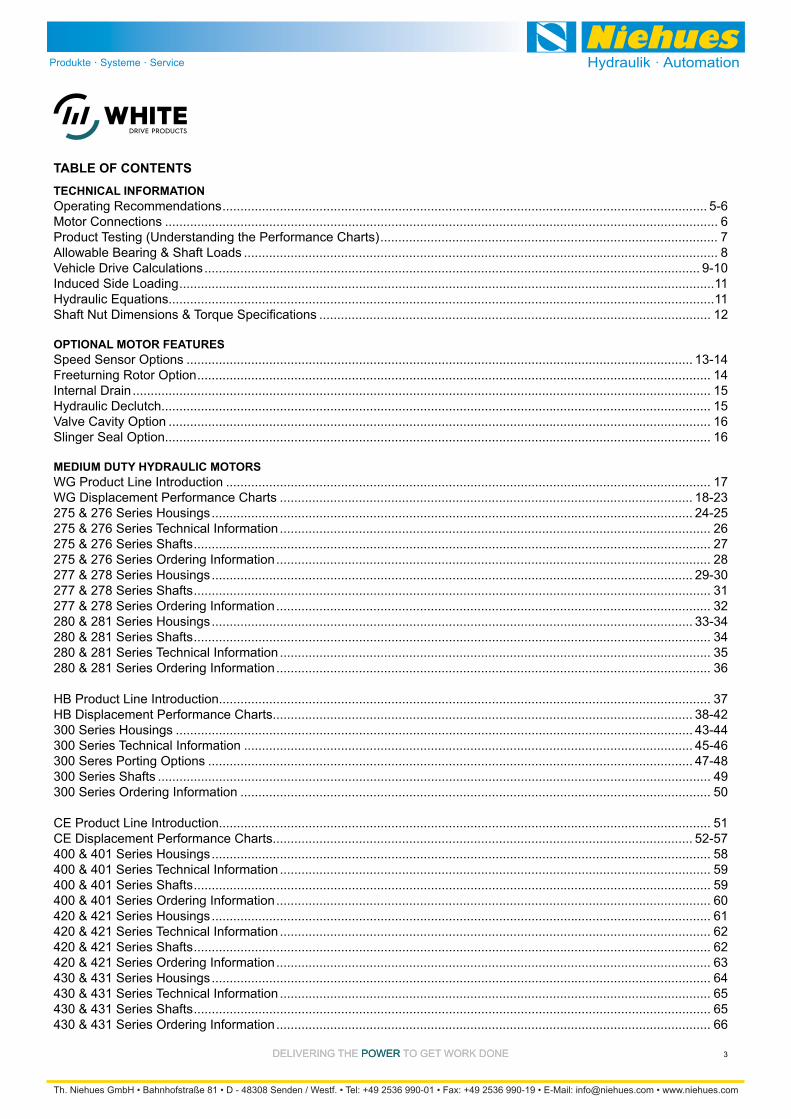
TABLE OF CONTENTSTECHNICAL INFORMATIONOperating Recommendations ....................................................................................................................................... 5-6Motor Connections .......................................................................................................................................................... 6Product Testing (Understanding the Performance Charts) .............................................................................................. 7Allowable Bearing & Shaft Loads .................................................................................................................................... 8Vehicle Drive Calculations .......................................................................................................................................... 9-10Induced Side Loading .....................................................................................................................................................11Hydraulic Equations........................................................................................................................................................11
............................................................................................................. 12
OPTIONAL MOTOR FEATURESSpeed Sensor Options ............................................................................................................................................. 13-14Freeturning Rotor Option ............................................................................................................................................... 14Internal Drain ................................................................................................................................................................. 15Hydraulic Declutch......................................................................................................................................................... 15Valve Cavity Option ....................................................................................................................................................... 16Slinger Seal Option........................................................................................................................................................ 16
MEDIUM DUTY HYDRAULIC MOTORSWG Product Line Introduction ....................................................................................................................................... 17WG Displacement Performance Charts ................................................................................................................... 18-23275 & 276 Series Housings ...................................................................................................................................... 24-25275 & 276 Series Technical Information ........................................................................................................................ 26275 & 276 Series Shafts ................................................................................................................................................ 27275 & 276 Series Ordering Information ......................................................................................................................... 28277 & 278 Series Housings ...................................................................................................................................... 29-30277 & 278 Series Shafts ................................................................................................................................................ 31277 & 278 Series Ordering Information ......................................................................................................................... 32280 & 281 Series Housings ...................................................................................................................................... 33-34280 & 281 Series Shafts ................................................................................................................................................ 34280 & 281 Series Technical Information ........................................................................................................................ 35280 & 281 Series Ordering Information ......................................................................................................................... 36
HB Product Line Introduction......................................................................................................................................... 37HB Displacement Performance Charts..................................................................................................................... 38-42300 Series Housings ................................................................................................................................................ 43-44300 Series Technical Information ............................................................................................................................. 45-46300 Seres Porting Options ....................................................................................................................................... 47-48300 Series Shafts .......................................................................................................................................................... 49300 Series Ordering Information ................................................................................................................................... 50
CE Product Line Introduction......................................................................................................................................... 51CE Displacement Performance Charts..................................................................................................................... 52-57400 & 401 Series Housings ........................................................................................................................................... 58400 & 401 Series Technical Information ........................................................................................................................ 59400 & 401 Series Shafts ................................................................................................................................................ 59400 & 401 Series Ordering Information ......................................................................................................................... 60420 & 421 Series Housings ........................................................................................................................................... 61420 & 421 Series Technical Information ........................................................................................................................ 62420 & 421 Series Shafts ................................................................................................................................................ 62420 & 421 Series Ordering Information ......................................................................................................................... 63430 & 431 Series Housings ........................................................................................................................................... 64430 & 431 Series Technical Information ........................................................................................................................ 65430 & 431 Series Shafts ................................................................................................................................................ 65430 & 431 Series Ordering Information ......................................................................................................................... 66

DELIVERING THE POWER TO GET WORK DONEDELIVERING THE POWER TO GET WORK DONE4
TABLE OF CONTENTS
RE Product Line Introduction......................................................................................................................................... 67RE Displacement Performance Charts..................................................................................................................... 68-73505 & 506 Series Housings ...................................................................................................................................... 74-75505 & 506 Series Technical Information ........................................................................................................................ 76505 & 506 Series Shafts ................................................................................................................................................ 77505 & 506 Series Ordering Information ......................................................................................................................... 78520 & 521 Series Housings ........................................................................................................................................... 79520 & 521 Series Technical Information ........................................................................................................................ 80520 & 521 Series Shafts ................................................................................................................................................ 81520 & 521 Series Ordering Information ......................................................................................................................... 82530 & 531 Series Housings ........................................................................................................................................... 83530 & 531 Series Technical Information ........................................................................................................................ 84530 & 531 Series Shafts ................................................................................................................................................ 85530 & 531 Series Ordering Information ......................................................................................................................... 86535 & 536 Series Housings ........................................................................................................................................... 87535 & 536 Series Technical Information ........................................................................................................................ 87535 & 536 Series Shafts ................................................................................................................................................ 88535 & 536 Series Ordering Information ......................................................................................................................... 88540 & 541 Series Housings ........................................................................................................................................... 89540 & 541 Series Technical Information ........................................................................................................................ 90540 & 541 Series Ordering Information ......................................................................................................................... 90

DELIVERING THE POWER TO GET WORK DONEDELIVERING THE POWER TO GET WORK DONE 5
OPERATING RECOMMENDATIONSOIL TYPE
are recommended for systems incorporating White Drive Products motors. Straight oils can be used but may require VI (viscosity index) improvers depending on the operating temperature range of the system. Other water based and environmentally friendly oils may be used, but service life of the motor and other components in the system may be
-
for compatibility. Testing under actual operating conditions is the only way to determine if acceptable service life will be achieved.
FLUID VISCOSITY & FILTRATIONFluids with a viscosity between 20 - 43 cSt [100 - 200 S.U.S.] at operating temperature is recommended. Fluid temperature should also be maintained below 85°C [180° F]. It is also suggested that the type of pump and its oper-
cavitation at the inlet side of the pump. Systems that operate over a wide range of temperatures may require viscosity
White Drive Products recommends maintaining an oil clean-liness level of ISO 17-14 or better.
INSTALLATION & START-UPWhen installing a White Drive Products motor it is important
the mounting surface of the application. Mounting hardware of the appropriate grade and size must be used. Hubs, pul-
avoid inducing excessive thrust or radial loads. Although
never be used to install any type of output device onto the shaft. The port plugs should only be removed from the mo-tor when the system connections are ready to be made. To avoid contamination, remove all matter from around the
system connections are made, it is recommended that the motor be run-in for 15-30 minutes at no load and half speed to remove air from the hydraulic system.
MOTOR PROTECTIONOver-pressurization of a motor is one of the primary causes of motor failure. To prevent these situations, it is necessary to provide adequate relief protection for a motor based on the pressure ratings for that particular model. For systems that may experience overrunning conditions, special pre-
energy into hydraulic energy. Unless the system is properly
can occur. To protect against this condition a counterbal-ance valve or relief cartridge must be incorporated into the
cartridge is used, it must be installed upline of the motor, if not in the motor, to relieve the pressure created by the over-running motor. To provide proper motor protection for an over-running load application, the pressure setting of the pressure relief valve must not exceed the intermittent rating of the motor.
HYDRAULIC MOTOR SAFETY PRECAUTIONA hydraulic motor must not be used to hold a suspended load. Due to the necessary internal tolerances, all hydraulic motors will experience some degree of creep when a load induced torque is applied to a motor at rest. All applica-tions that require a load to be held must use some form of
MOTOR/BRAKE PRECAUTIONCaution! - -
-cuitry must be designed to bring the load to a stop before
Caution! - Because it is possible for some large displace-
maximum system pressure be limited for these applications. Failure to do so could cause serious injury or death. When
performance chart for the series and displacement chosen for the application to verify that the maximum operating pressure of the system will not allow the motor to produce
it is vital that the system relief be set low enough to insure
option is not recommended due to the possibility of return -
34 bar [500 psi] pressure reducing valve is recommended
However, if a pressure reducing valve is used in a system
valve should be set to 34 bar [500 psi] over the expected
before all connections are tightened. To facilitate this op-
DELIVERING THE POWER TO GET WORK DONEDELIVERING THE POWER TO GET WORK DONE6
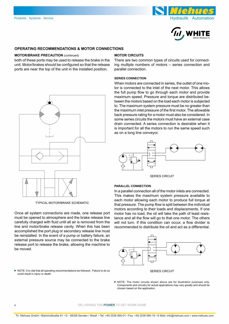
OPERATING RECOMMENDATIONS & MOTOR CONNECTIONSMOTOR CIRCUITSThere are two common types of circuits used for connect-ing multiple numbers of motors – series connection and parallel connection.
SERIES CONNECTION
When motors are connected in series, the outlet of one mo-tor is connected to the inlet of the next motor. This allows
maximum speed. Pressure and torque are distributed be-tween the motors based on the load each motor is subjected to. The maximum system pressure must be no greater than
some series circuits the motors must have an external case drain connected. A series connection is desirable when it is important for all the motors to run the same speed such as on a long line conveyor.
SERIES CIRCUIT
PARALLEL CONNECTION
In a parallel connection all of the motor inlets are connected.
each motor allowing each motor to produce full torque at
motors according to their loads and displacements. If one -
recommended to distribute the oil and act as a differential.
SERIES CIRCUIT
NOTE: The motor circuits shown above are for illustration purposes only. Components and circuitry for actual applications may vary greatly and should be chosen based on the application.
ports are near the top of the unit in the installed position.
MOTOR/BRAKE PRECAUTION (continued)
Once all system connections are made, one release port
accomplished the port plug or secondary release line must be reinstalled. In the event of a pump or battery failure, an
be moved.
NOTE: It is vital that all operating recommendations be followed. Failure to do so could result in injury or death.
TYPICAL MOTOR/BRAKE SCHEMATIC
DELIVERING THE POWER TO GET WORK DONEDELIVERING THE POWER TO GET WORK DONE 7
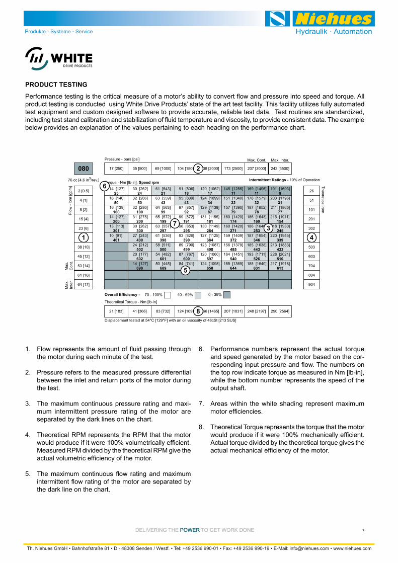
the motor during each minute of the test.
Pressure refers to the measured pressure differential between the inlet and return ports of the motor during the test.
The maximum continuous pressure rating and maxi-mum intermittent pressure rating of the motor are
Theoretical RPM represents the RPM that the motor
Measured RPM divided by the theoretical RPM give the
product testing is conducted using White Drive Products’ state of the art test facility. This facility utilizes fully automated test equipment and custom designed software to provide accurate, reliable test data. Test routines are standardized,
below provides an explanation of the values pertaining to each heading on the performance chart.
PRODUCT TESTING
Performance numbers represent the actual torque and speed generated by the motor based on the cor-
the top row indicate torque as measured in Nm [lb-in], while the bottom number represents the speed of the output shaft.
Areas within the white shading represent maximum
Theoretical Torque represents the torque that the motor
Actual torque divided by the theoretical torque gives the
1.
2.
3.
4.
5.
6.
7.
8.
25
50
100
200
301
401
24
50
100
200
300
400
502
602
690
21
43
99
199
297
398
500
601
689
18
43
92
191
295
390
499
600
688
17
34
87
181
284
384
498
597
658
11
32
79
174
271
372
485
540
644
11
32
78
160
253
346
443
526
631
9
31
77
154
245
339
433
510
613
[127]
[140]
[139]
[127]
[113]
[91]
14
16
16
14
13
10
[262]
[286]
[280]
[275]
[262]
[243]
[212]
[177]
[127]
30
32
32
31
30
27
24
20
14
[543]
[559]
[563]
[572]
[557]
[536]
[511]
[482]
[445]
61
63
64
65
63
61
58
54
50
[806]
[839]
[857]
[872]
[853]
[826]
[790]
[767]
[741]
91
95
97
99
96
93
89
87
84
[1062]
[1099]
[1139]
[1155]
[1149]
[1125]
[1087]
[1060]
[1098]
120
124
129
131
130
127
123
120
124
[1285]
[1340]
[1390]
[1420]
[1420]
[1409]
[1379]
[1451]
[1369]
145
151
157
160
160
159
156
164
155
[1496]
[1579]
[1652]
[1643]
[1646]
[1654]
[1638]
[1711]
[1640]
169
178
187
186
186
187
185
193
185
[1693]
[1796]
[1865]
[1911]
[1930]
[1945]
[1883]
[2021]
[1918]
191
203
211
216
218
220
213
228
217
Flow
- lp
m [g
pm]
17 [250] 35 [500] 69 [1000] 104 [1500] 138 [2000] 173 [2500] 207 [3000] 242 [3500]
Pressure - bars [psi]
21 [183] 41 [366] 83 [732] 124 [1099] 166 [1465] 207 [1831] 248 [2197] 290 [2564]
Theoretical Torque - Nm [lb-in]
Max
.In
ter.
Max
.C
ont.
76 cc [4.6 in3/rev.]
080
2 [0.5]
4 [1]
8 [2]
15 [4]
23 [6]
30 [8]
38 [10]
45 [12]
53 [14]
61 [16]
64 [17]
26
51
101
201
302
402
503
603
704
804
904
Theoretical rpm
Overall Efficiency - 70 - 100% 40 - 69% 0 - 39%
Intermittent Ratings - 10% of Operation
Displacement tested at 54°C [129°F] with an oil viscosity of 46cSt [213 SUS]
Max. Inter.Max. Cont.
1
2
34
5
8
7
Torque - Nm [lb-in], Speed rpm6
DELIVERING THE POWER TO GET WORK DONEDELIVERING THE POWER TO GET WORK DONE8
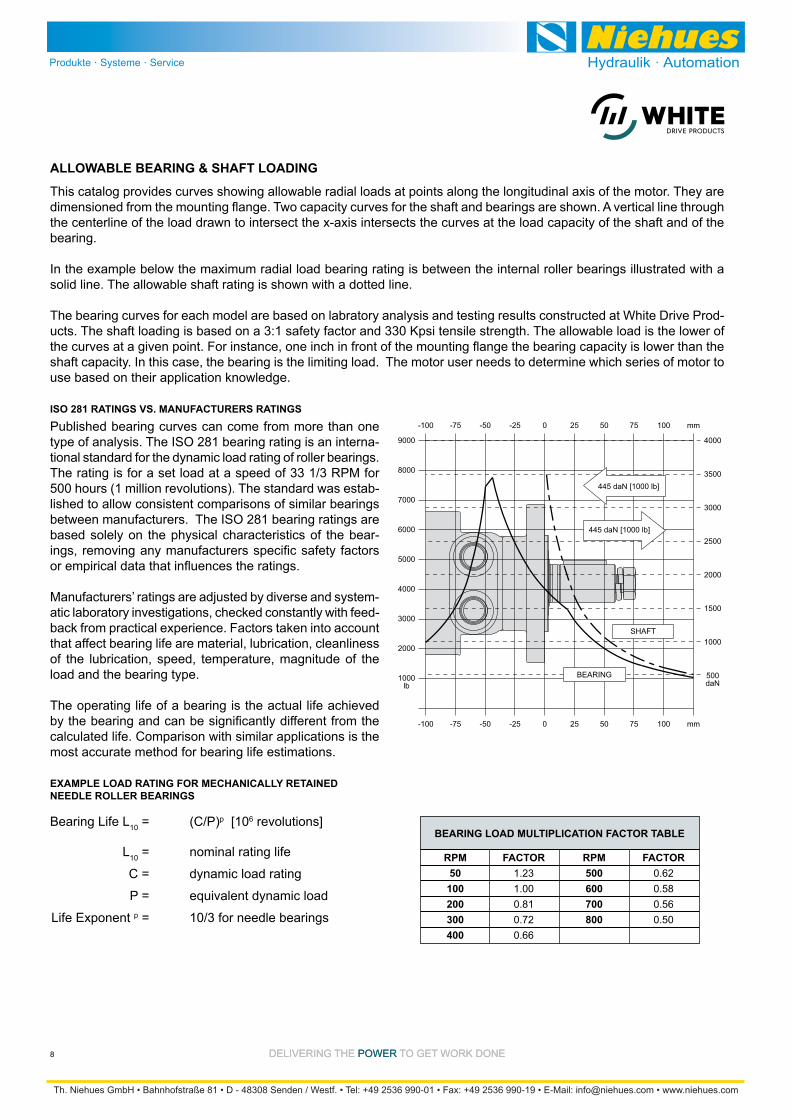
This catalog provides curves showing allowable radial loads at points along the longitudinal axis of the motor. They are
the centerline of the load drawn to intersect the x-axis intersects the curves at the load capacity of the shaft and of the bearing.
In the example below the maximum radial load bearing rating is between the internal roller bearings illustrated with a solid line. The allowable shaft rating is shown with a dotted line.
The bearing curves for each model are based on labratory analysis and testing results constructed at White Drive Prod-ucts. The shaft loading is based on a 3:1 safety factor and 330 Kpsi tensile strength. The allowable load is the lower of
shaft capacity. In this case, the bearing is the limiting load. The motor user needs to determine which series of motor to
Published bearing curves can come from more than one type of analysis. The ISO 281 bearing rating is an interna-tional standard for the dynamic load rating of roller bearings. The rating is for a set load at a speed of 33 1/3 RPM for 500 hours (1 million revolutions). The standard was estab-lished to allow consistent comparisons of similar bearings between manufacturers. The ISO 281 bearing ratings are based solely on the physical characteristics of the bear-
Manufacturers’ ratings are adjusted by diverse and system--
that affect bearing life are material, lubrication, cleanliness of the lubrication, speed, temperature, magnitude of the load and the bearing type.
The operating life of a bearing is the actual life achieved
calculated life. Comparison with similar applications is the most accurate method for bearing life estimations.
ALLOWABLE BEARING & SHAFT LOADING
9000
8000
7000
6000
5000
4000
3000
2000
1000lb
4000
3500
3000
2500
2000
1500
1000
500daN
445 daN [1000 lb]
445 daN [1000 lb]
BEARING
SHAFT
-100 -50 -25 0 25 50 75 100 mm-75
-100 -50 -25 0 25 50 75 100 mm-75
ISO 281 RATINGS VS. MANUFACTURERS RATINGS
EXAMPLE LOAD RATING FOR MECHANICALLY RETAINED NEEDLE ROLLER BEARINGS
Bearing Life L10 = (C/P)p [106 revolutions]
L10 = nominal rating life
C = dynamic load rating
P = equivalent dynamic load Life Exponent p = 10/3 for needle bearings
BEARING LOAD MULTIPLICATION FACTOR TABLE
RPM FACTOR RPM FACTOR 50 1.23 500 0.62 100 1.00 600 0.58 200 0.81 700 0.56 300 0.72 800 0.50 400 0.66
DELIVERING THE POWER TO GET WORK DONEDELIVERING THE POWER TO GET WORK DONE 9
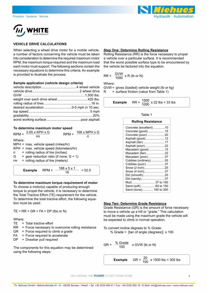
Step One: Determine Rolling ResistanceRolling Resistance (RR) is the force necessary to propel a vehicle over a particular surface. It is recommended that the worst possible surface type to be encountered by the vehicle be factored into the equation.
When selecting a wheel drive motor for a mobile vehicle,
into consideration to determine the required maximum motor RPM, the maximum torque required and the maximum load each motor must support. The following sections contain the necessary equations to determine this criteria. An example is provided to illustrate the process.
Concrete (excellent) .............10Concrete (good)....................15Concrete (poor) ....................20Asphalt (good) ......................12Asphalt (fair) .........................17Asphalt (poor) .......................22Macadam (good) ..................15Macadam (fair) .....................22Macadam (poor) ...................37Cobbles (ordinary) ................55Cobbles (poor) ......................37Snow (2 inch)........................25Snow (4 inch)........................37Dirt (smooth) .........................25Dirt (sandy) ...........................37Mud............................37 to 150Sand (soft) .................60 to 150Sand (dune) .............160 to 300
Table 1
Step Two: Determine Grade ResistanceGrade Resistance (GR) is the amount of force necessary to move a vehicle up a hill or “grade.” This calculation must be made using the maximum grade the vehicle will be expected to climb in normal operation.
To convert incline degrees to % Grade: % Grade = [tan of angle (degrees)] x 100
To determine maximum torque requirement of motorTo choose a motor(s) capable of producing enough torque to propel the vehicle, it is necessary to determine the Total Tractive Effort (TE) requirement for the vehicle. To determine the total tractive effort, the following equa-tion must be used:
TE = RR + GR + FA + DP (lbs or N)
Where:TE = Total tractive effortRR = Force necessary to overcome rolling resistanceGR = Force required to climb a gradeFA = Force required to accelerateDP = Drawbar pull required
The components for this equation may be determined using the following steps:
To determine maximum motor speed
Rolling Resistance
2.65 x KPH x GrmRPM =
Where:MPH = max. vehicle speed (miles/hr)
ri = rolling radius of tire (inches)G = gear reduction ratio (if none, G = 1)rm = rolling radius of tire (meters)
Sample application (vehicle design criteria)vehicle description .....................................4 wheel vehiclevehicle drive.................................................. 2 wheel driveGVW .................................................................1,500 lbs.weight over each drive wheel ................................425 lbs.rolling radius of tires ..................................................16 in.desired acceleration .............................0-5 mph in 10 sec.top speed ................................................................. 5 mphgradability ................................................................... 20%
.....................................poor asphalt
VEHICLE DRIVE CALCULATIONS
168 x MPH x GriRPM =
Example 168 x 5 x 116RPM = = 52.5
GVW1000RR = x R (lb or N)
Where:
R = surface friction (value from Table 1)
Example 15001000RR = x 22 lbs = 33 lbs
% Grade100GR = x GVW (lb or N)
Example 20100GR = x 1500 lbs = 300 lbs
DELIVERING THE POWER TO GET WORK DONEDELIVERING THE POWER TO GET WORK DONE10
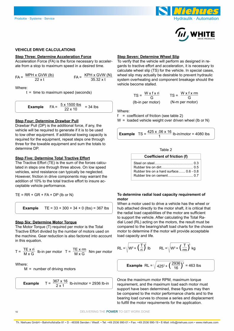
Step Three: Determine Acceleration ForceAcceleration Force (FA) is the force necessary to acceler-ate from a stop to maximum speed in a desired time.
Where: t = time to maximum speed (seconds)
Step Seven: Determine Wheel SlipTo verify that the vehicle will perform as designed in re-gards to tractive effort and acceleration, it is necessary to calculate wheel slip (TS) for the vehicle. In special cases, wheel slip may actually be desirable to prevent hydraulic
vehicle become stalled.
Where:
W = loaded vehicle weight over driven wheel (lb or N)
Steel on steel ........................................ 0.3Rubber tire on dirt ................................. 0.5Rubber tire on a hard surface ....... 0.6 - 0.8Rubber tire on cement .......................... 0.7
Table 2
To determine radial load capacity requirement of motorWhen a motor used to drive a vehicle has the wheel or hub attached directly to the motor shaft, it is critical that
to support the vehicle. After calculating the Total Ra-dial Load (RL) acting on the motors, the result must be compared to the bearing/shaft load charts for the chosen motor to determine if the motor will provide acceptable load capacity and life.
Once the maximum motor RPM, maximum torque requirement, and the maximum load each motor must
be compared to the motor performance charts and to the bearing load curves to choose a series and displacement
VEHICLE DRIVE CALCULATIONS
MPH x GVW (lb)22 x tFA = KPH x GVW (N)
35.32 x tFA =
Example FA = = 34 lbs5 x 1500 lbs22 x 10
Step Four: Determine Drawbar PullDrawbar Pull (DP) is the additional force, if any, thevehicle will be required to generate if it is to be used to tow other equipment. If additional towing capacity is required for the equipment, repeat steps one through three for the towable equipment and sum the totals to determine DP.
Step Five: Determine Total Tractive EffortThe Tractive Effort (TE) is the sum of the forces calcu-lated in steps one through three above. On low speed vehicles, wind resistance can typically be neglected. However, friction in drive components may warrant the addition of 10% to the total tractive effort to insure ac-ceptable vehicle performance.
TE = RR + GR + FA + DP (lb or N)
Example TE = 33 + 300 + 34 + 0 (lbs) = 367 lbs
Step Six: Determine Motor TorqueThe Motor Torque (T) required per motor is the Total Tractive Effort divided by the number of motors used on the machine. Gear reduction is also factored into account in this equation.
TE x riM x GT = lb-in per motor TE x rm
M x GT = Nm per motor
Where: M = number of driving motors
Example T = lb-in/motor = 2936 lb-in367 x 162 x 1
(N-m per motor)(lb-in per motor)
W x f x riGTS = W x f x rm
GTS =
Example TS = lb-in/motor = 4080 lbs425 x .06 x 161
RL = W2 + ( ) lbT 2
ri RL = W2 + ( ) T 2
rm
Example RL = 4252 + ( )2293616 = 463 lbs
DELIVERING THE POWER TO GET WORK DONEDELIVERING THE POWER TO GET WORK DONE 11
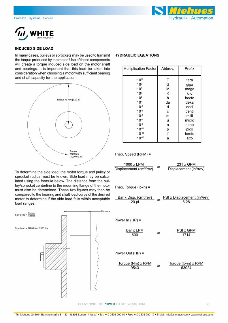
the torque produced by the motor. Use of these components will create a torque induced side load on the motor shaft
and shaft capacity for the application. 1012 T tera109 G giga106 M mega103
102 h hecto101
10-1 d deci10-2 c centi10-3 m milli10-6 u micro10-9 n nano10-12 p pico10-15 f femto10-18 a atto
Multiplication Factor Abbrev.
HYDRAULIC EQUATIONS
INDUCED SIDE LOAD
Radius 76 mm [3.00 in]
Torque1129 Nm[10000 lb-in]
To determine the side load, the motor torque and pulley or -
lated using the formula below. The distance from the pul-
compared to the bearing and shaft load curve of the desired motor to determine if the side load falls within acceptable load ranges.
DistanceSide Load =
Side Load = 14855 Nm [3333 lbs]
TorqueRadius
Theo. Speed (RPM) =
1000 x LPMDisplacement (cm3/rev) or 231 x GPM
Displacement (in3/rev)
Bar x Disp. (cm3/rev)20 pi
Theo. Torque (lb-in) =
or PSI x Displacement (in3/rev)6.28
PSI x GPM1714
Bar x LPM600
Power In (HP) =
or
Torque (lb-in) x RPM63024
Torque (Nm) x RPM9543
Power Out (HP) =
or
DELIVERING THE POWER TO GET WORK DONEDELIVERING THE POWER TO GET WORK DONE12
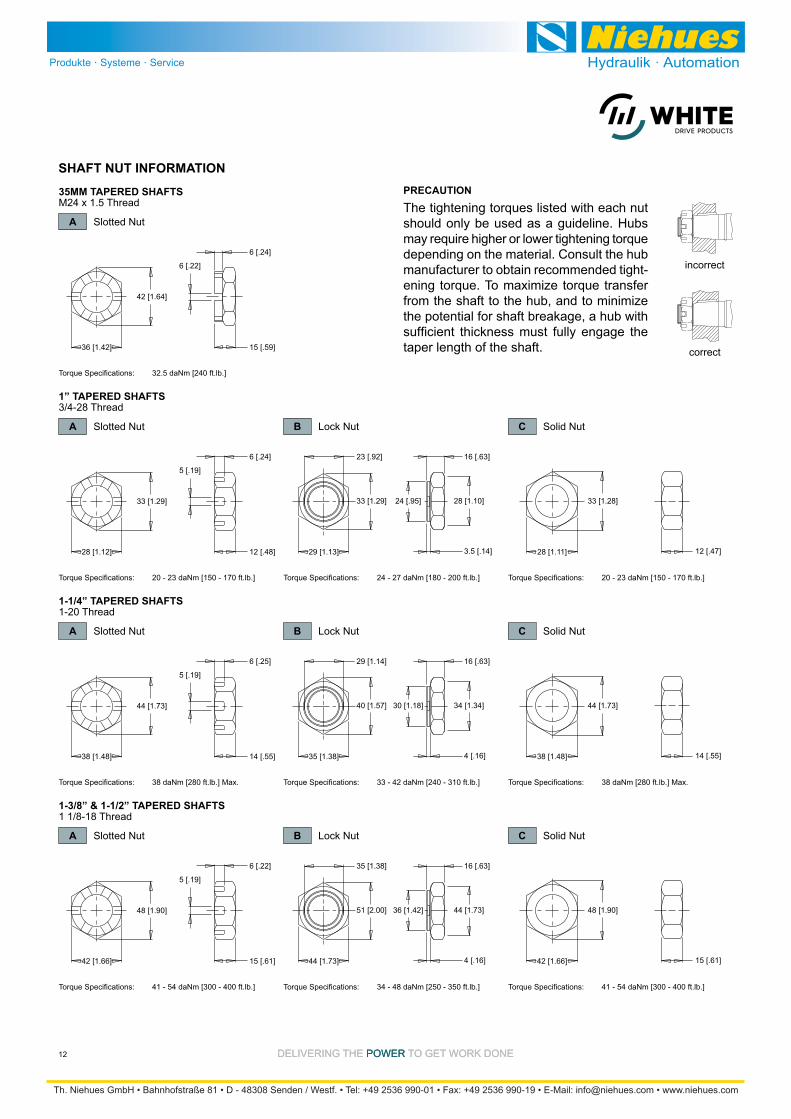
A Slotted Nut
35MM TAPERED SHAFTS
B Lock Nut
B Lock Nut
B Lock Nut
C Solid Nut
C Solid Nut
C Solid Nut
M24 x 1.5 Thread
A Slotted Nut
1” TAPERED SHAFTS3/4-28 Thread
A Slotted Nut
1-1/4” TAPERED SHAFTS1-20 Thread
A Slotted Nut
1-3/8” & 1-1/2” TAPERED SHAFTS1 1/8-18 Thread
33 [1.29]
5 [.19]
6 [.24]
12 [.48]
Torque Specifications: 20 - 23 daNm [150 - 170 ft.lb.]
29 [1.13]28 [1.12]
42 [1.64]
6 [.22]
6 [.24]
15 [.59]
Torque Specifications: 32.5 daNm [240 ft.lb.]
36 [1.42]
16 [.63]
3.5 [.14]
33 [1.29]
28 [1.11] 12 [.47]
33 [1.28]
23 [.92]
24 [.95] 28 [1.10]
Torque Specifications: 24 - 27 daNm [180 - 200 ft.lb.] Torque Specifications: 20 - 23 daNm [150 - 170 ft.lb.]
44 [1.73]
5 [.19]
6 [.25]
14 [.55]
Torque Specifications: 38 daNm [280 ft.lb.] Max.
35 [1.38]38 [1.48]
16 [.63]
4 [.16]
40 [1.57]
38 [1.48] 14 [.55]
44 [1.73]
29 [1.14]
30 [1.18] 34 [1.34]
Torque Specifications: 33 - 42 daNm [240 - 310 ft.lb.] Torque Specifications: 38 daNm [280 ft.lb.] Max.
48 [1.90]
5 [.19]
6 [.22]
15 [.61]
Torque Specifications: 41 - 54 daNm [300 - 400 ft.lb.]
44 [1.73]42 [1.66]
16 [.63]
4 [.16]
51 [2.00]
42 [1.66] 15 [.61]
48 [1.90]
35 [1.38]
36 [1.42] 44 [1.73]
Torque Specifications: 34 - 48 daNm [250 - 350 ft.lb.] Torque Specifications: 41 - 54 daNm [300 - 400 ft.lb.]
The tightening torques listed with each nut should only be used as a guideline. Hubs may require higher or lower tightening torque depending on the material. Consult the hub manufacturer to obtain recommended tight-ening torque. To maximize torque transfer from the shaft to the hub, and to minimize
taper length of the shaft.
SHAFT NUT INFORMATIONPRECAUTION
correct
incorrect
DELIVERING THE POWER TO GET WORK DONEDELIVERING THE POWER TO GET WORK DONE 13
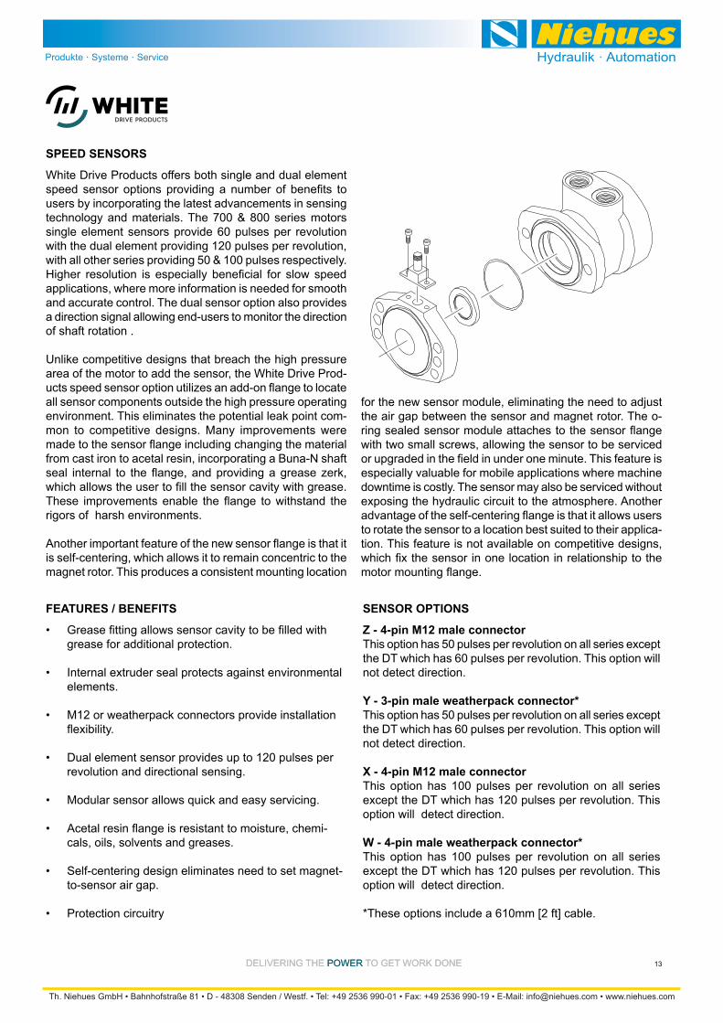
White Drive Products offers both single and dual element
users by incorporating the latest advancements in sensing technology and materials. The 700 & 800 series motors single element sensors provide 60 pulses per revolution with the dual element providing 120 pulses per revolution, with all other series providing 50 & 100 pulses respectively.
applications, where more information is needed for smooth and accurate control. The dual sensor option also provides a direction signal allowing end-users to monitor the direction of shaft rotation .
area of the motor to add the sensor, the White Drive Prod-
all sensor components outside the high pressure operating -
mon to competitive designs. Many improvements were
from cast iron to acetal resin, incorporating a Buna-N shaft
rigors of harsh environments.
is self-centering, which allows it to remain concentric to the magnet rotor. This produces a consistent mounting location
Z - 4-pin M12 male connectorThis option has 50 pulses per revolution on all series except the DT which has 60 pulses per revolution. This option will not detect direction.
Y - 3-pin male weatherpack connector*This option has 50 pulses per revolution on all series except the DT which has 60 pulses per revolution. This option will not detect direction.
X - 4-pin M12 male connectorThis option has 100 pulses per revolution on all series except the DT which has 120 pulses per revolution. This option will detect direction.
W - 4-pin male weatherpack connector*This option has 100 pulses per revolution on all series except the DT which has 120 pulses per revolution. This option will detect direction.
*These options include a 610mm [2 ft] cable.
SENSOR OPTIONS
SPEED SENSORS
grease for additional protection.
Internal extruder seal protects against environmental elements.
Dual element sensor provides up to 120 pulses per revolution and directional sensing.
-cals, oils, solvents and greases.
Self-centering design eliminates need to set magnet-to-sensor air gap.
Protection circuitry
FEATURES / BENEFITS
for the new sensor module, eliminating the need to adjust the air gap between the sensor and magnet rotor. The o-
with two small screws, allowing the sensor to be serviced
especially valuable for mobile applications where machine downtime is costly. The sensor may also be serviced without exposing the hydraulic circuit to the atmosphere. Another
to rotate the sensor to a location best suited to their applica-tion. This feature is not available on competitive designs,

DELIVERING THE POWER TO GET WORK DONEDELIVERING THE POWER TO GET WORK DONE14
SINGLE ELEMENT SENSOR - Y & Z
DUAL ELEMENT SENSOR - X & W
Supply voltages ................................................7.5-24 VdcMaximum output off voltage .......................................24 VMaximum continuous output current .................... < 25 ma Signal levels (low, high) .................... 0.8 to supply voltageOperating Temp ................-30°C to 83°C [-22°F to 181°F]
Supply voltages ................................................7.5-18 VdcMaximum output off voltage .......................................18 VMaximum continuous output current .................... < 20 ma Signal levels (low, high) .................... 0.8 to supply voltageOperating Temp ................-30°C to 83°C [-22°F to 181°F]
SENSOR CONNECTORS
PROTECTION CIRCUITRY
The single element sensor has been improved and in-corporates protection circuitry to avoid electrical damage caused by:
SPEED SENSORS
FREE TURNING ROTOR
The ‘AC’ option or “Free turning” option refers to a specially prepared rotor assembly. This rotor assembly has increased clearance between the rotor tips and rollers allowing it to turn more freely than a standard rotor assembly. For spool valve motors, additional clearance is also provided between the shaft and housing bore. The ‘AC’ option is available for all motor series and displacements.
There are several applications and duty cycle conditions where ‘AC’ option performance characteristics can be
-ditional clearance helps to minimize internal pressure drop
at metal to metal contact areas and can help extend the life of the motor in high rpm or even over speed conditions. The ‘AC’ option should be considered for applications that require continuous operation above 57 LPM [15 GPM] and/
by specifying the ‘AC’ option. The additional clearance
be bypassed through the motor rather than being absorbed
12
34
PIN 1 positive brown or red 2 n/a white 3 negative blue 4 pulse out black
Z Option
12
34
PIN 1 positive brown or red 2 direction out white 3 negative blue 4 pulse out black
X Option
PIN A positive brown or red B negative blue C pulse out black D n/a whiteC B A
Y Option
CD B A
PIN A positive brown or red B negative blue C pulse out black D direction out white
W Option
surges (60 Vdc max.)
The protection circuit feature will help “save” the sensor from damage mentioned above caused by:
failure or harness damage resulting from accidental conditions (i.e. severed or grounded wire, ice, etc.)
electrical/electronic components that may be intermittent or damaged and “loading down” the system.
While no protection circuit can guarantee against any and all fault conditions. The single element sensor from White Drive Products with protection circuitry is designed to handle potential hazards commonly seen in real world applications.
Unprotected versions are also available for operation at lower voltages down to 4.5V.

DELIVERING THE POWER TO GET WORK DONEDELIVERING THE POWER TO GET WORK DONE 15
each port of the endcover. During normal motor operation, pressure in the input and return lines of the motor close the
valve between the case and low pressure line opens, al-
pressure differential, the internal drain option operates in either direction of motor rotation.
Although this option can simplify many motor installations, -
sure remains below allowable levels (see table below) to insure proper motor operation and life. If return line pressure
-ing catastrophic seal failure. Installing motors with internal drains in series is not recommended unless overall pres-sure drop over all motors is below the maximum allowable
your authorized White Drive Products representative.
The declutch or ‘AE’ option, available on the RE and CE -
tions requiring the motor to have the ability to “freewheel”
components, the torque required to turn the output shaft is minimal. Selection of this option allows freewheeling speeds up to 1,000 RPM* depending on the displacement of the motor and duty cycle of the application.
To enable the motor to perform this function, the standard rotor assembly is replaced with a freeturn rotor assembly. Next, the standard balance plate and endcover is replaced with a special wear plate and ported endcover. The wear
to each other. The ported endcover features a movable piston capable of sealing the seven holes in the wear plate.
When standard motor function is required, pressure is supplied to the endcover port, moving the piston against the wear plate. This action seals the seven holes allowing the motor to function as normal. However, when pressure is removed from the endcover port, the pressure created by the turning rotor assembly pushes the piston away from
this condition, oil may circulate freely within the rotor and endcover assemblies, allowing the rotor assembly to rotate freely within the motor.
This option is especially useful in applications ranging from winch drives to towable wheel drives. Depending on the valves and hydrau-lic circuitry, operation of the freewheel function may be manually or automatically selected. A basic schematic is shown to the right.
The internal drain is an option available on all HB, DR, and DT Series motors, and is standard on all WP, WR, WS, and D9 series motors. Typically, a separate drain line
to the reservoir when using a HB, DR, or DT Series motor. However, the internal drain option eliminates the need for
requirements for the motor.
INTERNAL DRAIN
HYDRAULIC DECLUTCH
Series Cont. bar [psi] Inter. bar [psi] HB 69 [1000] 103 [1500]
DR 69 [1000] 103 [1500]
DT 21 [300] 34 [500]
D9 21 [300] 21 [300]
Brakes 34 [500] 34 [500]
MAXIMUM ALLOWABLEBACK PRESSURE
through the motor to provide cooling.
DELIVERING THE POWER TO GET WORK DONEDELIVERING THE POWER TO GET WORK DONE16
The valve cavity option provides a cost effective way to incorporate a variety of cartridge valves integral to the mo-tor. The valve cavity is a standard 10 series (12 series on the 800 series motor) 2-way cavity that accepts numerous
and high pressure shuttle valves. Installation of a relief car-tridge into the cavity provides an extra margin of safety for
cartridges from 69 to 207 bar [1000 to 3000 psi] may also be factory installed.
VALVE CAVITY
into the valve cavity to provide a simple method for con-trolling motor speed. It is also possible to incorporate the speed sensor option and a programmable logic controller
fully automated speed control system. For motors with
into the cavity to provide a simple, fully integrated method for supplying release pressure to the pilot line to actuate an
cavity option, contact an authorized White Drive Products distributor.
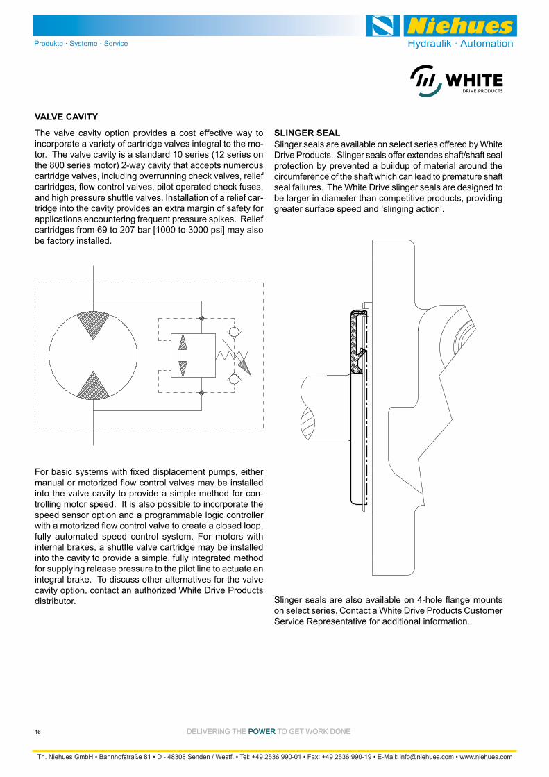
Slinger seals are available on select series offered by White Drive Products. Slinger seals offer extendes shaft/shaft seal protection by prevented a buildup of material around the circumference of the shaft which can lead to premature shaft seal failures. The White Drive slinger seals are designed to be larger in diameter than competitive products, providing greater surface speed and ‘slinging action’.
SLINGER SEAL
on select series. Contact a White Drive Products Customer Service Representative for additional information.

DELIVERING THE POWER TO GET WORK DONE
For Medium Duty ApplicationsWG (All Series)
17
Max. Speed Max. Flow Max. Torque Max. Pressure rpm lpm [gpm] Nm [lb-in] bar [psi]
040 41 [2.5] 830 1020 34 [9] 42 [11] 71 [630] 100 [870] 138 [2000] 190 [2750] 207 [3000]045 44 [2.7] 770 940 34 [9] 42 [11] 78 [685] 108 [955] 138 [2000] 190 [2750] 207 [3000]060 60 [3.6] 760 950 45 [12] 57 [15] 107 [950] 150 [1320] 138 [2000] 190 [2750] 207 [3000]
070 70 [4.3] 650 810 45 [12] 57 [15] 127 [1120] 176 [1560] 138 [2000] 190 [2750] 207 [3000] 090 88 [5.4] 520 650 45 [12] 57 [15] 162 [1430] 224 [1985] 138 [2000] 190 [2750] 207 [3000] 100 100 [6.1] 450 570 45 [12] 57 [15] 185 [1640] 257 [2275] 138 [2000] 190 [2750] 207 [3000] 130 129 [7.9] 350 440 45 [12] 57 [15] 241 [2135] 334 [2960] 138 [2000] 190 [2750] 207 [3000] 160 161 [9.8] 280 350 45 [12] 57 [15] 304 [2690] 421 [3730] 138 [2000] 190 [2750] 207 [3000] 200 200 [12.2] 220 280 45 [12] 57 [15] 379 [3350] 525 [4650] 138 [2000] 190 [2750] 207 [3000] 230 231 [14.1] 240 330 57 [15] 76 [20] 380 [3380] 529 [4680] 121 [1750] 165 [2400] 200 [2900] 320 322 [19.7] 175 235 57 [15] 76 [20] 458 [4050] 600 [5300] 103 [1500] 134 [1950] 169 [2450] 400 404 [24.4] 140 185 57 [15] 76 [20] 548 [4850] 758 [6710] 100 [1450] 135 [1960] 170 [2460]
CODE Displacement cm3 [in3/rev] cont. inter. cont. inter. cont. inter. cont. inter. peak
SPECIFICATIONS
The White Drive Products tradition of providing motors that excel in demanding applications continues with the WG series. WG motors provide an exceptionally solid platform for any light-duty application where sideload may present a concern. The WG incorporates our Roller Stator® design which reduces friction and extends motor life. With displace-ments ranging from 41 - 404 cm3 [2.5 - 24.4 in3] per revolu-tion and a choice of mounting, shaft, and port options, this motor is made to satisfy a variety of applications. The WG
long motor life at an affordable price.
OVERVIEW
Needle Roller Bearing is in optimum location to allow load to be placed as close to the center line of bearing as possible.
High Pressure Buna® Shaft Seal offers superior seal life and performance and eliminates the need for a case drain.
provide long life.
life by using roller contact versus solid, sliding contact design.
Rubber Energized Steel Face Seal does not extrude or melt under high pressure or high temperature.
FEATURES / BENEFITS
SERIES DESCRIPTIONS
Performance data is typical. Performance of production units varies slightly from one motor to another. Running at intermittent ratings should not exceed 10% of every minute of operation.
conveyors, carwashes, positioners, light to medium-duty wheel drives, sweepers, grain augers, spreaders, feed rollers, screw drives, brush drives and more
TYPICAL APPLICATIONS
275/276 - Hydraulic Motor Standard
277/278 - Hydraulic Motor
280/281 - Hydraulic Motor
DELIVERING THE POWER TO GET WORK DONE
For Medium Duty ApplicationsWG (All Series)
18
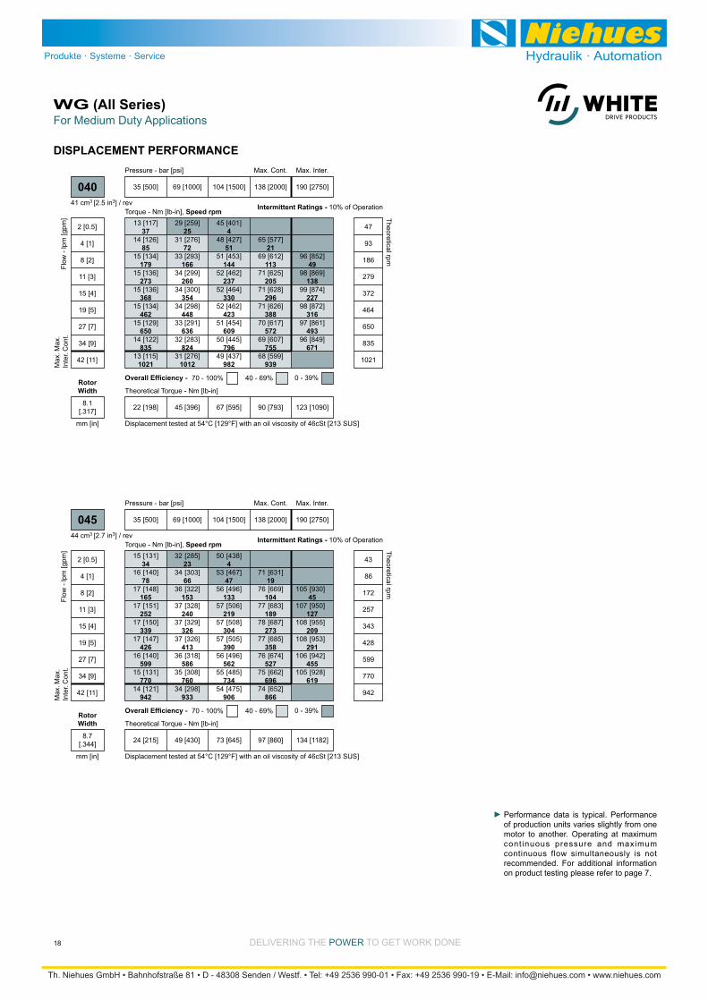
DISPLACEMENT PERFORMANCE
Performance data is typical. Performance of production units varies slightly from one motor to another. Operating at maximum continuous pressure and maximum continuous flow simultaneously is not recommended. For additional information on product testing please refer to page 7.
13 [117]37
14 [126]85
15 [134]179
15 [136]273
15 [136]368
15 [134]462
15 [129]650
14 [122]835
13 [115]1021
Torque - Nm [lb-in], Speed rpm
Flow
- lp
m [g
pm]
35 [500] 69 [1000] 104 [1500] 138 [2000] 190 [2750]
Max. Inter.Max. Cont.
Theoretical Torque - Nm [lb-in]
Max
.In
ter.
Max
.C
ont.
040
Theoretical rpm
Overall Efficiency - 70 - 100% 40 - 69% 0 - 39%
Intermittent Ratings - 10% of Operation
29 [259]25
31 [276]72
33 [293]166
34 [299]260
34 [300]354
34 [298]448
33 [291]636
32 [283]824
31 [276]1012
45 [401]4
48 [427]51
51 [453]144
52 [462]237
52 [464]330
52 [462]423
51 [454]609
50 [445]796
49 [437]982
65 [577]21
69 [612]113
71 [625]205
71 [628]296
71 [626]388
70 [617]572
69 [607]755
68 [599]939
2 [0.5]
4 [1]
8 [2]
11 [3]
15 [4]
19 [5]
27 [7]
34 [9]
42 [11]
47
93
186
279
372
464
650
835
1021
96 [852]49
98 [869]138
99 [874]227
98 [872]316
97 [861]493
96 [849]671
22 [198] 45 [396] 67 [595] 90 [793] 123 [1090]
Displacement tested at 54°C [129°F] with an oil viscosity of 46cSt [213 SUS]
Pressure - bar [psi]
41 cm3 [2.5 in3] / rev
mm [in]
RotorWidth
8.1[.317]
34
78
165
252
339
426
599
770
942
23
66
153
240
326
413
586
760
933
4
47
133
219
304
390
562
734
906
19
104
189
273
358
527
696
866
45
127
209
291
455
619
[131]
[140]
[148]
[151]
[150]
[147]
[140]
[131]
[121]
15
16
17
17
17
17
16
15
14
[285]
[303]
[322]
[328]
[329]
[326]
[318]
[308]
[298]
32
34
36
37
37
37
36
35
34
[438]
[467]
[496]
[506]
[508]
[505]
[496]
[485]
[475]
50
53
56
57
57
57
56
55
54
[631]
[669]
[683]
[687]
[685]
[674]
[662]
[652]
71
76
77
78
77
76
75
74
[930]
[950]
[955]
[953]
[942]
[928]
105
107
108
108
106
105
Torque - Nm [lb-in], Speed rpm
Flow
- lp
m [g
pm]
35 [500] 69 [1000] 104 [1500] 138 [2000] 190 [2750]
Max. Inter.Max. Cont.
Theoretical Torque - Nm [lb-in]
Max
.In
ter.
Max
.C
ont.
045
Theoretical rpm
Overall Efficiency - 70 - 100% 40 - 69% 0 - 39%
Intermittent Ratings - 10% of Operation
2 [0.5]
4 [1]
8 [2]
11 [3]
15 [4]
19 [5]
27 [7]
34 [9]
42 [11]
43
86
172
257
343
428
599
770
942
24 [215] 49 [430] 73 [645] 97 [860] 134 [1182]
Displacement tested at 54°C [129°F] with an oil viscosity of 46cSt [213 SUS]
Pressure - bar [psi]
44 cm3 [2.7 in3] / rev
mm [in]
RotorWidth
8.7[.344]

DELIVERING THE POWER TO GET WORK DONE
For Medium Duty ApplicationsWG (All Series)
19
DISPLACEMENT PERFORMANCE
Performance data is typical. Performance of production units varies slightly from one motor to another. Operating at maximum continuous pressure and maximum continuous flow simultaneously is not recommended. For additional information on product testing please refer to page 7.
26
58
122
187
251
316
445
572
762
952
17
49
113
178
242
306
435
563
756
949
3
35
98
162
226
289
417
544
735
926
14
77
140
203
265
391
517
705
893
34
94
155
216
337
459
641
[191]
[203]
[213]
[214]
[211]
[205]
[190]
[170]
[136]
[98]
22
23
24
24
24
23
21
19
15
11
[400]
[425]
[450]
[458]
[458]
[453]
[437]
[417]
[384]
[349]
45
48
51
52
52
51
49
47
43
39
[608]
[648]
[687]
[702]
[704]
[700]
[685]
[664]
[632]
[599]
69
73
78
79
80
79
77
75
71
68
[870]
[924]
[945]
[950]
[948]
[932]
[912]
[879]
[850]
98
104
107
107
107
105
103
99
96
[1280]
[1310]
[1320]
[1319]
[1304]
[1282]
[1251]
145
148
149
149
147
145
141
Torque - Nm [lb-in], Speed rpm
Flow
- lp
m [g
pm]
35 [500] 69 [1000] 104 [1500] 138 [2000] 190 [2750]
Max. Inter.Max. Cont.
Theoretical Torque - Nm [lb-in]
Max
.In
ter.
Max
.C
ont.
060
Theoretical rpm
Overall Efficiency - 70 - 100% 40 - 69% 0 - 39%
Intermittent Ratings - 10% of Operation
Displacement tested at 54°C [129°F] with an oil viscosity of 46cSt [213 SUS]
2 [0.5]
4 [1]
8 [2]
11 [3]
15 [4]
19 [5]
27 [7]
34 [9]
45 [12]
57 [15]
32
64
127
191
254
318
445
572
762
952
33 [292] 65 [580] 98 [869] 131 [1159] 180 [1594]
Pressure - bar [psi]
60 cm3 [3.6 in3] / rev
mm [in]
RotorWidth
11.8[.463]
22
50
105
160
215
271
381
490
653
816
15
42
97
152
207
262
372
483
648
813
2
30
84
139
193
248
357
466
630
793
12
66
120
174
227
335
442
604
765
29
81
133
185
289
393
549
[231]
[244]
[255]
[256]
[251]
[243]
[222]
[196]
[149]
[96]
[474]
[504]
[534]
[542]
[541]
[535]
[514]
[488]
[443]
[393]
[718]
[765]
[812]
[829]
[831]
[827]
[807]
[781]
[736]
[690]
[1025]
[1090]
[1115]
[1121]
[1119]
[1100]
[1073]
[1030]
[986]
[1507]
[1544]
[1557]
[1556]
[1539]
[1512]
[1470]
26
28
29
29
28
27
25
22
17
11
54
57
60
61
61
60
58
55
50
44
81
86
92
94
94
93
91
88
83
78
116
123
126
127
126
124
121
116
111
170
175
176
176
174
171
166
Torque - Nm [lb-in], Speed rpm
Flow
- lp
m [g
pm]
35 [500] 69 [1000] 104 [1500] 138 [2000] 190 [2750]
Max. Inter.Max. Cont.
Theoretical Torque - Nm [lb-in]
Max
.In
ter.
Max
.C
ont.
070
Theoretical rpm
Overall Efficiency - 70 - 100% 40 - 69% 0 - 39%
Intermittent Ratings - 10% of Operation
Displacement tested at 54°C [129°F] with an oil viscosity of 46cSt [213 SUS]
2 [0.5]
4 [1]
8 [2]
11 [3]
15 [4]
19 [5]
27 [7]
34 [9]
45 [12]
57 [15]
28
55
109
164
218
272
381
490
653
816
38 [338] 76 [667] 115 [1015] 153 [1354] 210 [1861]
Pressure - bar [psi]
70 cm3 [4.3 in3] / rev
mm [in]
RotorWidth
13.8[.542]
DELIVERING THE POWER TO GET WORK DONE
For Medium Duty ApplicationsWG (All Series)
20
DISPLACEMENT PERFORMANCE
17
39
83
127
171
215
303
389
519
648
12
33
77
121
165
208
296
383
515
646
2
24
67
110
154
197
284
370
500
630
10
52
95
138
181
266
351
480
608
23
64
106
147
230
312
436
[301]
[318]
[331]
[331]
[323]
[312]
[280]
[242]
[173]
[94]
[609]
[647]
[684]
[694]
[692]
[683]
[654]
[616]
[549]
[473]
[917]
[967]
[1036]
[1058]
[1061]
[1055]
[1028]
[990]
[925]
[853]
[1305]
[1388]
[1421]
[1430]
[1427]
[1402]
[1365]
[1301]
[1232]
[1917]
[1966]
[1984]
[1984]
[1962]
[1926]
[1864]
34
36
37
37
37
35
32
27
20
11
69
73
77
78
78
77
74
70
62
53
104
110
117
120
120
119
116
112
105
96
147
157
161
162
161
158
154
147
139
217
222
224
224
222
218
211
Torque - Nm [lb-in], Speed rpm
Flow
- lp
m [g
pm]
35 [500] 69 [1000] 104 [1500] 138 [2000] 190 [2750]
Max. Inter.Max. Cont.
Theoretical Torque - Nm [lb-in]
Max
.In
ter.
Max
.C
ont.
090
Theoretical rpm
Overall Efficiency - 70 - 100% 40 - 69% 0 - 39%
Intermittent Ratings - 10% of Operation
Displacement tested at 54°C [129°F] with an oil viscosity of 46cSt [213 SUS]
2 [0.5]
4 [1]
8 [2]
11 [3]
15 [4]
19 [5]
27 [7]
34 [9]
45 [12]
57 [15]
22
44
87
130
173
216
303
389
519
648
48 [426] 96 [852] 144 [1278] 193 [1704] 265 [2343]
Pressure - bar [psi]
88 cm3 [5.4 in3] / rev
mm [in]
RotorWidth
17.3[.682]
15
35
73
112
150
189
266
341
455
569
10
29
68
106
144
183
260
336
451
566
2
21
59
97
135
173
249
325
439
553
9
46
83
121
158
233
308
421
533
20
56
93
129
201
274
383
[350]
[369]
[383]
[382]
[372]
[358]
[320]
[273]
[190]
[93]
[701]
[744]
[786]
[798]
[795]
[784]
[749]
[703]
[622]
[528]
[1052]
[1120]
[1189]
[1214]
[1218]
[1211]
[1178]
[1133]
[1053]
[964]
[1496]
[1592]
[1630]
[1641]
[1637]
[1607]
[1564]
[1485]
[1399]
[2196]
[2254]
[2275]
[2276]
[2251]
[2209]
[2133]
40
42
43
43
42
40
36
31
21
10
79
84
89
90
90
89
85
79
70
60
119
128
134
137
138
137
133
128
119
109
169
180
184
185
185
182
177
168
158
248
255
257
257
254
250
241
Torque - Nm [lb-in], Speed rpm
Flow
- lp
m [g
pm]
35 [500] 69 [1000] 104 [1500] 138 [2000] 190 [2750]
Max. Inter.Max. Cont.
Theoretical Torque - Nm [lb-in]
Max
.In
ter.
Max
.C
ont.
100
Theoretical rpm
Overall Efficiency - 70 - 100% 40 - 69% 0 - 39%
Intermittent Ratings - 10% of Operation
Displacement tested at 54°C [129°F] with an oil viscosity of 46cSt [213 SUS]
2 [0.5]
4 [1]
8 [2]
11 [3]
15 [4]
19 [5]
27 [7]
34 [9]
45 [12]
57 [15]
19
38
76
114
152
190
266
341
455
569
55 [486] 110 [971] 165 [1457] 220 [1943] 302 [2671]
Pressure - bar [psi]
100 cm3 [6.1 in3] / rev
mm [in]
RotorWidth
19.7[.777]
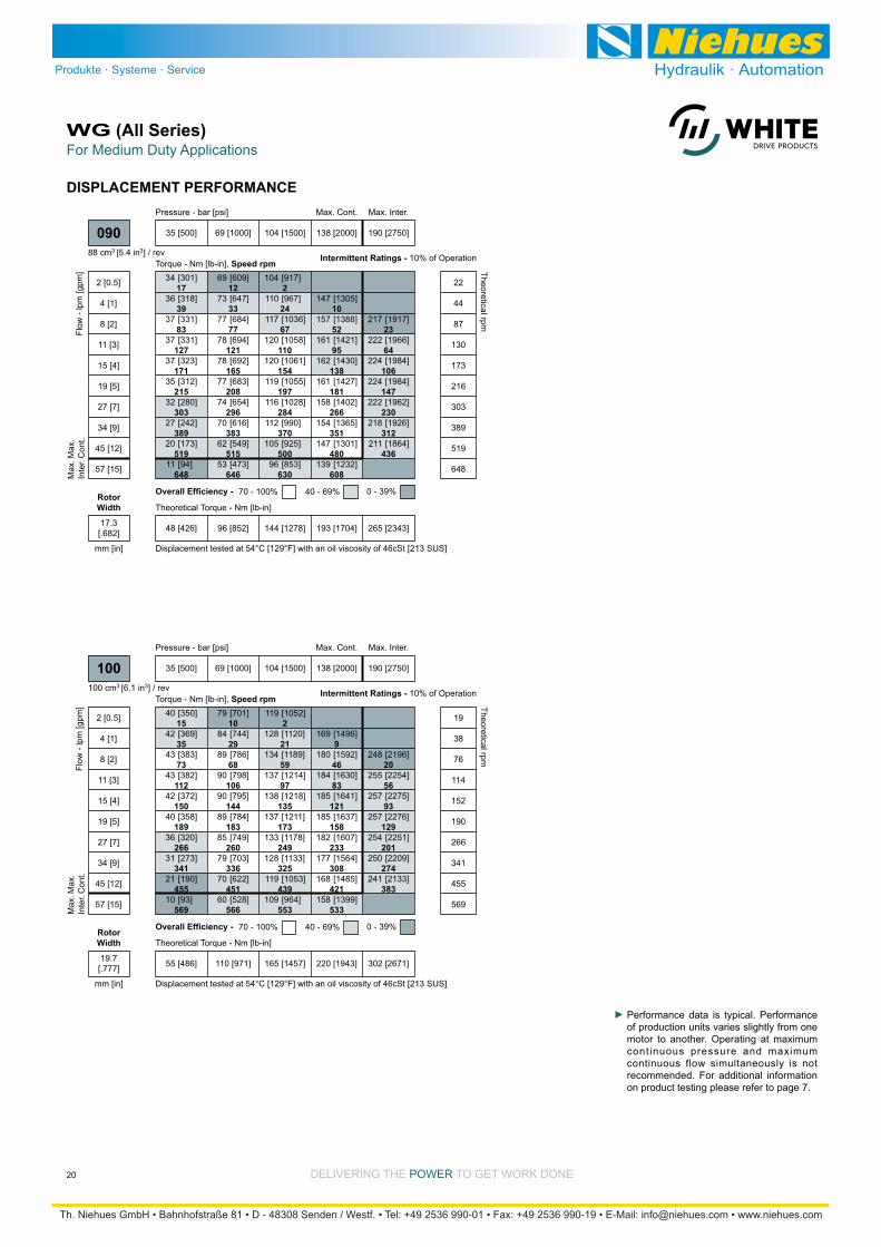
Performance data is typical. Performance of production units varies slightly from one motor to another. Operating at maximum continuous pressure and maximum continuous flow simultaneously is not recommended. For additional information on product testing please refer to page 7.

DELIVERING THE POWER TO GET WORK DONE
For Medium Duty ApplicationsWG (All Series)
21
DISPLACEMENT PERFORMANCE
12
27
57
87
116
146
206
265
353
441
8
23
53
82
112
142
201
261
350
440
1
16
46
75
105
134
193
252
341
429
7
36
65
94
123
181
239
326
414
16
44
72
100
156
213
297
[463]
[487]
[505]
[502]
[488]
[413]
[413]
[347]
[228]
[89]
[917]
[972]
[1026]
[1041]
[1037]
[1021]
[972]
[908]
[792]
[657]
[1370]
[1458]
[1548]
[1580]
[1586]
[1576]
[1531]
[1469]
[1355]
[1224]
[1943]
[2069]
[2120]
[2134]
[2130]
[2091]
[2030]
[1919]
[1792]
[2851]
[2929]
[2958]
[2961]
[2929]
[2872]
[2764]
52
55
57
57
55
53
47
39
26
10
104
110
116
118
117
115
110
103
89
74
155
165
175
179
179
178
173
166
153
138
220
234
240
241
241
239
229
217
202
322
331
334
335
331
325
312
Torque - Nm [lb-in], Speed rpm
Flow
- lp
m [g
pm]
35 [500] 69 [1000] 104 [1500] 138 [2000] 190 [2750]
Max. Inter.Max. Cont.
Theoretical Torque - Nm [lb-in]
Max
.In
ter.
Max
.C
ont.
130
Theoretical rpm
Overall Efficiency - 70 - 100% 40 - 69% 0 - 39%
Intermittent Ratings - 10% of Operation
Displacement tested at 54°C [129°F] with an oil viscosity of 46cSt [213 SUS]
2 [0.5]
4 [1]
8 [2]
11 [3]
15 [4]
19 [5]
27 [7]
34 [9]
45 [12]
57 [15]
15
30
59
89
118
147
206
265
353
441
71 [626] 141 [1252] 212 [1877] 283 [2503] 389 [3442]
Pressure - bar [psi]
129 cm3 [7.9 in3] / rev
mm [in]
RotorWidth
25.4[1.002]
9
21
45
69
93
117
165
212
282
353
6
18
42
66
90
113
161
209
280
351
1
13
36
60
84
107
154
202
272
343
5
29
52
75
98
145
191
261
331
12
35
57
80
125
170
237
[590]
[620]
[641]
[636]
[617]
[590]
[518]
[429]
[271]
[85]
[1158]
[1228]
[1295]
[1313]
[1307]
[1287]
[1222]
[1137]
[982]
[800]
[1726]
[1836]
[1949]
[1991]
[1997]
[1984]
[1927]
[1845]
[1693]
[1516]
[2445]
[2604]
[2668]
[2687]
[2682]
[2631]
[2552]
[2404]
[2231]
[3585]
[3684]
[3722]
[3728]
[3688]
[3614]
[3471]
67
70
72
72
70
67
59
49
31
10
131
139
146
148
148
145
138
128
111
90
195
207
220
225
226
224
218
208
191
171
276
294
301
304
303
297
288
272
252
405
416
421
421
417
408
392
Torque - Nm [lb-in], Speed rpm
Flow
- lp
m [g
pm]
35 [500] 69 [1000] 104 [1500] 138 [2000] 190 [2750]
Max. Inter.Max. Cont.
Theoretical Torque - Nm [lb-in]
Max
.In
ter.
Max
.C
ont.
160
Theoretical rpm
Overall Efficiency - 70 - 100% 40 - 69% 0 - 39%
Intermittent Ratings - 10% of Operation
Displacement tested at 54°C [129°F] with an oil viscosity of 46cSt [213 SUS]
2 [0.5]
4 [1]
8 [2]
11 [3]
15 [4]
19 [5]
27 [7]
34 [9]
45 [12]
57 [15]
12
24
47
71
94
118
165
212
282
353
88 [783] 177 [1565] 265 [2348] 354 [3131] 486 [4305]
Pressure - bar [psi]
161 cm3 [9.8 in3] / rev
mm [in]
RotorWidth
31.8[1.252]
Performance data is typical. Performance of production units varies slightly from one motor to another. Operating at maximum continuous pressure and maximum continuous flow simultaneously is not recommended. For additional information on product testing please refer to page 7.
DELIVERING THE POWER TO GET WORK DONE
For Medium Duty ApplicationsWG (All Series)
22
DISPLACEMENT PERFORMANCE
84
88
91
90
87
83
73
60
36
9
164
173
183
185
184
181
172
159
137
110
243
259
275
280
281
280
271
259
237
211
344
367
376
378
378
371
359
337
312
504
519
524
525
519
509
488
[742]
[778]
[804]
[796]
[772]
[736]
[643]
[528]
[322]
[80]
[1447]
[1534]
[1617]
[1639]
[1631]
[1605]
[1522]
[1411]
[1210]
[973]
[2152]
[2289]
[2430]
[2482]
[2490]
[2474]
[2400]
[2295]
[2098]
[1865]
[3045]
[3244]
[3325]
[3349]
[3343]
[3279]
[3178]
[2985]
[2758]
[4464]
[4589]
[4638]
[4646]
[4597]
[4503]
[4317]
Torque - Nm [lb-in], Speed rpm
Flow
- lp
m [g
pm]
35 [500] 69 [1000] 104 [1500] 138 [2000] 190 [2750]
Max. Inter.Max. Cont.
Theoretical Torque - Nm [lb-in]
Max
.In
ter.
Max
.C
ont.
200
Theoretical rpm
Overall Efficiency - 70 - 100% 40 - 69% 0 - 39%
Intermittent Ratings - 10% of Operation
Displacement tested at 54°C [129°F] with an oil viscosity of 46cSt [213 SUS]
2 [0.5]
4 [1]
8 [2]
11 [3]
15 [4]
19 [5]
27 [7]
34 [9]
45 [12]
57 [15]
10
19
38
57
76
95
133
171
228
285
110 [971] 219 [1941] 329 [2912] 439 [3882] 603 [5338]
8
17
37
56
75
94
133
171
228
285
5
15
34
53
72
91
130
168
226
283
1
10
29
48
67
86
124
163
220
277
4
23
42
61
79
117
154
210
267
10
28
46
64
101
137
192
Pressure - bar [psi]
200 cm3 [12.2 in3] / rev
mm [in]
RotorWidth
39.4[1.552]
7
15
32
48
65
82
115
148
197
247
4
13
29
46
63
79
112
146
196
245
328
1
9
25
42
58
75
108
141
190
240
322
7
23
39
56
72
105
137
186
236
317
4
20
36
52
69
101
134
182
231
14
30
46
62
94
126
174
222
98
102
106
104
101
96
84
69
41
9
190
201
212
215
214
210
199
184
157
125
62
282
300
318
325
326
324
314
300
274
242
181
349
371
380
382
381
372
358
332
301
240
398
425
435
438
438
429
416
390
359
510
523
528
529
521
508
483
453
[864]
[905]
[934]
[925]
[895]
[853]
[743]
[607]
[364]
[76]
[1678]
[1779]
[1875]
[1900]
[1890]
[1860]
[1761]
[1631]
[1393]
[1111]
[551]
[2493]
[2652]
[2816]
[2876]
[2885]
[2866]
[2780]
[2655]
[2422]
[2145]
[1600]
[3089]
[3286]
[3363]
[3382]
[3369]
[3289]
[3167]
[2936]
[2662]
[2124]
[3526]
[3757]
[3851]
[3880]
[3872]
[3798]
[3679]
[3451]
[3180]
[4509]
[4631]
[4675]
[4677]
[4612]
[4498]
[4274]
[4007]
Torque - Nm [lb-in], Speed rpm
Flow
- lp
m [g
pm]
35 [500] 69 [1000] 104 [1500] 121 [1750] 138 [2000] 166 [2400]
Max. Inter.Max. Cont.
Theoretical Torque - Nm [lb-in]
Max
.In
ter.
Max
.C
ont.
230
Theoretical rpm
Overall Efficiency - 70 - 100% 40 - 69% 0 - 39%
Intermittent Ratings - 10% of Operation
Displacement tested at 54°C [129°F] with an oil viscosity of 46cSt [213 SUS]
2 [0.5]
4 [1]
8 [2]
11 [3]
15 [4]
19 [5]
27 [7]
34 [9]
45 [12]
57 [15]
76 [20]
9
17
33
50
66
83
115
148
197
247
329
127 [1121] 253 [2242] 380 [3363] 443 [3924] 507 [4484] 608 [5381]
Pressure - bar [psi]
231 cm3 [14.1 in3] / rev
mm [in]
RotorWidth
45.5[1.791]
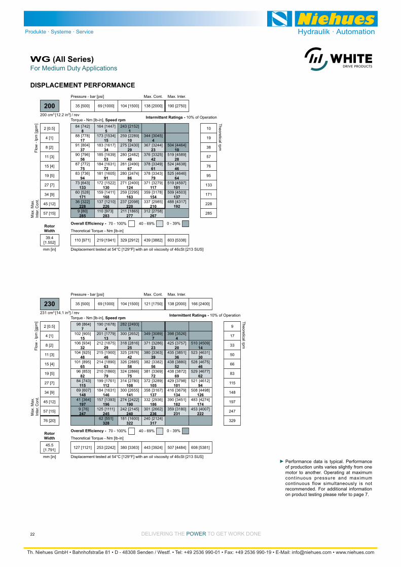
Performance data is typical. Performance of production units varies slightly from one motor to another. Operating at maximum continuous pressure and maximum continuous flow simultaneously is not recommended. For additional information on product testing please refer to page 7.

DELIVERING THE POWER TO GET WORK DONE
For Medium Duty ApplicationsWG (All Series)
23
DISPLACEMENT PERFORMANCE
11
23
35
47
59
82
106
142
177
9
21
33
45
57
81
104
140
176
235
18
30
42
54
77
101
136
172
231
15
26
38
50
73
96
131
166
[2501]
[2635]
[2670]
[2654]
[2610]
[2468]
[2279]
[1931]
[1517]
[692]
[3951]
[4036]
[4049]
[4021]
[3897]
[3717]
[3377]
[2970]
[2160]
[5136]
[5265]
[5303]
[5291]
[5184]
[5012]
[4678]
[4277]
[1280]
[1319]
[1304]
[1260]
[1199]
[1039]
[841]
[485]
[64]
145
149
147
142
135
117
95
55
7
283
298
302
300
295
279
258
218
171
78
447
456
457
454
440
420
382
336
244
580
595
599
598
586
566
529
483
Torque - Nm [lb-in], Speed rpm
Flow
- lp
m [g
pm]
35 [500] 69 [1000] 104 [1500] 134 [1950]
Max. Inter.Max. Cont.
Theoretical Torque - Nm [lb-in]
Max
.In
ter.
Max
.C
ont.
320
Theoretical rpm
Overall Efficiency - 70 - 100% 40 - 69% 0 - 39%
Intermittent Ratings10% of Operation
4 [1]
8 [2]
11 [3]
15 [4]
19 [5]
27 [7]
34 [9]
45 [12]
57 [15]
76 [20]
12
24
36
48
59
83
106
142
177
236
177 [1564] 354 [3129] 530 [4693] 689 [6102]
Displacement tested at 54°C [129°F] with an oil viscosity of 46cSt [213 SUS]
Pressure - bar [psi]
322 cm3 [19.7 in3] / rev
mm [in]
RotorWidth
63.5[2.501]
3
12
22
34
45
60
71
95
119
139
186
3
11
18
32
44
55
69
91
117
138
184
7
16
28
37
45
58
86
112
135
183
5
13
24
29
36
49
79
109
133
171
210
211
207
192
188
176
144
112
85
11
341
353
373
386
377
370
365
327
293
266
180
537
548
546
531
545
534
513
476
433
337
687
693
732
753
758
737
719
688
643
[1513]
[1858]
[1867]
[1832]
[1699]
[1664]
[1558]
[1274]
[991]
[752]
[97]
[3018]
[3124]
[3301]
[3416]
[3336]
[3274]
[3230]
[2894]
[2593]
[2354]
[1593]
[4752]
[4850]
[4832]
[4699]
[4823]
[4726]
[4540]
[4212]
[3832]
[2982]
[6080]
[6133]
[6478]
[6664]
[6708]
[6522]
[6363]
[6088]
[5690]
Torque - Nm [lb-in], Speed rpm
Flow
- lp
m [g
pm]
35 [500] 69 [1000] 104 [1500] 134 [1950]
Pressure - bar [psi] Max. Inter.Max. Cont.
Theoretical Torque - Nm [lb-in]
Max
.In
ter.
Max
.C
ont.
400
Theoretical rpm
Overall Efficiency - 70 - 100% 40 - 69% 0 - 39%
Intermittent Ratings10% of Operation
2 [0.5]
4 [1]
8 [2]
11 [3]
15 [4]
19 [5]
27 [7]
34 [9]
45 [12]
57 [15]
76 [20]
5
12
25
37
50
62
74
99
124
141
186
225 [1991] 450 [3982] 643 [5690] 868 [7681]
Displacement tested at 54°C [129°F] with an oil viscosity of 46cSt [213 SUS]
404 cm3 [24.4 in3] / rev
mm [in]
RotorWidth
63.5[2.501]
Performance data is typical. Performance of production units varies slightly from one motor to another. Operating at maximum continuous pressure and maximum continuous flow simultaneously is not recommended. For additional information on product testing please refer to page 7.
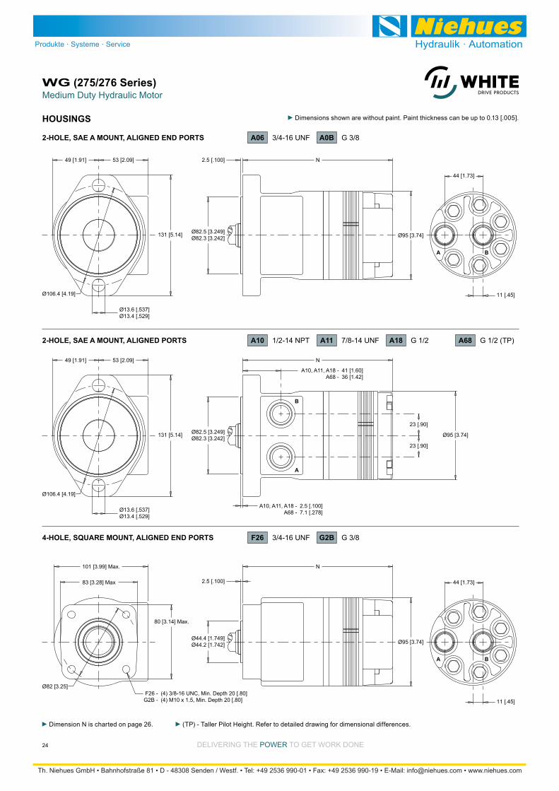
Medium Duty Hydraulic MotorWG (275/276 Series)
24 DELIVERING THE POWER TO GET WORK DONE
A
B
131 [5.14] Ø82.5 [3.249]Ø82.3 [3.242]
Ø106.4 [4.19]
53 [2.09] 2.5 [.100]49 [1.91]
Ø13.6 [.537]Ø13.4 [.529]
N
Ø95 [3.74]
A B
44 [1.73]
11 [.45]
Ø82 [3.25]
83 [3.28] Max 2.5 [.100]
101 [3.99] Max.
80 [3.14] Max.
N
Ø95 [3.74]
A B
44 [1.73]
11 [.45]
131 [5.14] Ø82.5 [3.249]Ø82.3 [3.242]
Ø44.4 [1.749]Ø44.2 [1.742]
Ø106.4 [4.19]
53 [2.09]49 [1.91]
Ø13.6 [.537]Ø13.4 [.529]
N
Ø95 [3.74]
23 [.90]
23 [.90]
A10, A11, A18 - 2.5 [.100] A68 - 7.1 [.278]
A10, A11, A18 - 41 [1.60] A68 - 36 [1.42]
F26 - (4) 3/8-16 UNC, Min. Depth 20 [.80] G2B - (4) M10 x 1.5, Min. Depth 20 [.80]
2-HOLE, SAE A MOUNT, ALIGNED PORTS
4-HOLE, SQUARE MOUNT, ALIGNED END PORTS
A10 1/2-14 NPT A11 7/8-14 UNF
G2B G 3/8
A0B G 3/8
F26 3/4-16 UNF
A18 G 1/2 A68 G 1/2 (TP)
2-HOLE, SAE A MOUNT, ALIGNED END PORTS A06 3/4-16 UNF
HOUSINGS
Dimension N is charted on page 26. (TP) - Taller Pilot Height. Refer to detailed drawing for dimensional differences.
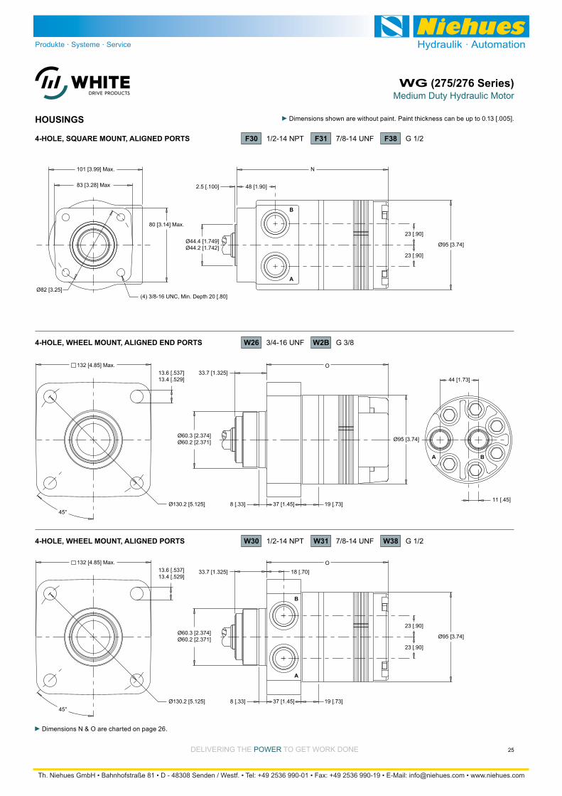
Medium Duty Hydraulic MotorWG (275/276 Series)
25DELIVERING THE POWER TO GET WORK DONE
A
B
45°
132 [4.85] Max.
Ø130.2 [5.125] 8 [.33]
O
A B
44 [1.73]
11 [.45]
A
B
Ø82 [3.25]
83 [3.28] Max 2.5 [.100] 48 [1.90]
101 [3.99] Max.
80 [3.14] Max.
N
Ø44.4 [1.749]Ø44.2 [1.742] Ø95 [3.74]
23 [.90]
23 [.90]
(4) 3/8-16 UNC, Min. Depth 20 [.80]
13.6 [.537]13.4 [.529]
Ø60.3 [2.374]Ø60.2 [2.371] Ø95 [3.74]
37 [1.45] 19 [.73]
33.7 [1.325]
45°
132 [4.85] Max.
Ø130.2 [5.125] 8 [.33]
O13.6 [.537]13.4 [.529]
Ø60.3 [2.374]Ø60.2 [2.371]
37 [1.45] 19 [.73]
33.7 [1.325] 18 [.70]
23 [.90]
23 [.90]
Ø95 [3.74]
4-HOLE, WHEEL MOUNT, ALIGNED END PORTS
4-HOLE, WHEEL MOUNT, ALIGNED PORTS
W26 3/4-16 UNF
W31 7/8-14 UNF
W2B G 3/8
W30 1/2-14 NPT W38 G 1/2
F30 1/2-14 NPT F31 7/8-14 UNF F38 G 1/24-HOLE, SQUARE MOUNT, ALIGNED PORTS
Dimensions N & O are charted on page 26.
HOUSINGS

Medium Duty Hydraulic MotorWG (275/276 Series)
26 DELIVERING THE POWER TO GET WORK DONE
LENGTH & WEIGHT CHARTDimension N is the overall motor length from the rear of the motor
is referenced on detailed housing drawings listed on pages 24-25.
Side Ports End Ports Weight N#
040045060070090100130160200230320400
kg [lb]
7.3 [15.9]
7.3 [16.0]
7.4 [16.3]
7.5 [16.4]
7.6 [16.8]
7.7 [17.0]
8.0 [17.5]
8.2 [18.0]
8.5 [18.7]
8.7 [19.2]
9.5 [20.8]
9.5 [20.8]
mm [in]
137 [5.39]
138 [5.43]
141 [5.55]
143 [5.63]
147 [5.79]
149 [5.87]
155 [6.10]
161 [6.34]
169 [6.65]
175 [6.89]
193 [7.60]
193 [7.60]
mm [in]
156 [6.16]
157 [6.19]
160 [6.31]
162 [6.38]
166 [6.52]
168 [6.62]
174 [6.84]
180 [7.09]
188 [7.39]
194 [7.63]
212 [8.34]
212 [8.34]housing, substract 4.5 [.178] from the dimension.
The bearing curve represents allowable bearing loads based on ISO 281 bearing capacity for an L10 life of 2,000 hours at 100 rpm. Radial loads for speeds other than 100 rpm may be calculated using the multiplication factor table on page 8.
ALLOWABLE SHAFT LOAD / BEARING CURVE
TECHNICAL INFORMATION
3000
8000
SAE A & SQUARE MOUNTS
7000
6000
5000
4000
lb
2000
1000
1000
3500
3000
2500
2000
1500
daN
500
2 in3-4 10-3 -1-2
50 mm75-100 250-75 -25-50
445 daN [1000 lb]
445 daN [1000 lb]
SHAFT
BEARING
3000
8000
WHEEL MOUNTS
7000
6000
5000
4000
lb
2000
1000
1000
3500
3000
2500
2000
1500
daN
500
3 in4-3 21-2 0-1
75 mm100-75 5025-50 0-25
445 daN [1000 lb]
445 daN [1000 lb]
SHAFT
BEARING
Dimension O is the overall motor length from the rear of the motor
is referenced on detailed housing drawings listed on page 25.
Side Ports End Ports Weight O#
040045060070090100130160200230320400
kg [lb]
7.6 [16.7]
7.6 [16.8]
7.7 [17.0]
7.8 [17.2]
8.0 [17.5]
8.0 [17.7]
8.3 [18.2]
8.5 [18.8]
8.9 [19.5]
9.1 [20.0]
9.8 [21.6]
9.8 [21.6]
mm [in]
106 [4.17]
106 [4.17]
110 [4.33]
112 [4.41]
115 [4.53]
118 [4.65]
123 [4.84]
130 [5.12]
137 [5.39]
144 [5.67]
162 [6.38]
162 [6.38]
mm [in]
125 [4.93]
125 [4.95]
129 [5.07]
131 [5.15]
134 [5.29]
137 [5.39]
142 [5.61]
149 [5.86]
156 [6.16]
163 [6.40]
181 [7.11]
181 [7.11]
The overall motor weights listed in both charts above are referencing the end ported options, -

Medium Duty Hydraulic MotorWG (275/276 Series)
27DELIVERING THE POWER TO GET WORK DONE
6 [.24]
30.9 [1.218]29.7 [1.168]8.0 [.314]
7.9 [.313]
25.4 [1.000]25.4 [.999]
5/16-18 UNC, Min. Depth 20 [.80]
27.8 [1.094]27.6 [1.085]
Ø25.0 [.985]Ø25.0 [.984]
P
40 [1.58]
P
P
M8 x 1.25, Min. Depth 20 [.80]
P2
6.4 [.251]6.4 [.250]
28.2 [1.110]28.0 [1.101]
6 [.24]
26.0 [1.020]24.6 [.970]
34 [1.34]
22 [.85]
4 [.16]
2.7 [.105]
6.4 [.251]6.4 [.250] 19.1 [.750]
18.3 [.720]
1:8 Taper2 [.09]
25.4 [1.000]25.4 [0.999]
Max. Torque: 655 Nm [5800 lb-in] Max. Torque: 678 Nm [6000 lb-in]
14 1” Tapered (SAE Standard)
Max. Torque: 655 Nm [5800 lb-in]
10 1” Straight 15 1” Straight Extended 12 25mm Straight 89 25mm Straight Stepdown
A slotted hex nut is standard on this shaft.
P
25 [1.00]
17 [.67]
4 [.16]
2.3 [.092]
4.8 [.189]4.8 [.188] 19.6 [.770]
18.3 [.720]
1:8 Taper2 [.10]
25.4 [1.000]25.4 [0.999]
13 1” Tapered
Max. Torque: 655 Nm [5800 lb-in]
A slotted hex nut is standard on this shaft.
SHAFTS
MOUNTING / SHAFT LENGTH CHART
Dimension P is the overall distance from the motor mounting surface to the end of the shaft.
Additional shaft length information, if necessary, is noted as P2 and does not increase or decrease the listed P dimensions in this chart. The overall shaft lengths are already factored into the overall distance from the mounting surface to the end of the shaft.
Square & A Wheel Mounts MountsP
#101213141589
mm [in]
N/A
43 [1.70]
N/A
N/A
N/A
45 [1.78]
mm [in]
45 [1.77]
49 [1.94]
56 [2.21]
61 [2.41]
64 [2.50]
51 [2.00]
mm [in]
76 [2.99]
80 [3.16]
87 [3.43]
92 [3.63]
95 [3.77]
82 [3.22]
P2
Add 4.5 [.178] to shaft dimension P when a A68 housing is used.
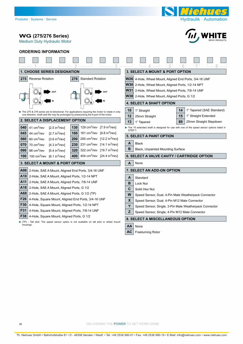
Medium Duty Hydraulic MotorWG (275/276 Series)
28 DELIVERING THE POWER TO GET WORK DONE
ORDERING INFORMATION
1 2 3 4 5 6 7 8
41 cm3/rev [2.5 in3/rev]
44 cm3/rev [2.7 in3/rev]
60 cm3/rev [3.6 in3/rev]
70 cm3/rev [4.3 in3/rev]
88 cm3/rev [5.4 in3/rev]
100 cm3/rev [6.1 in3/rev]
Reverse Rotation Standard Rotation
The 275 & 276 series are bi-directional. For applications requiring the motor to rotate in only one direction, shaft seal life may be prolonged by pressurizing the A port of the motor.
129 cm3/rev [7.9 in3/rev]
161 cm3/rev [9.8 in3/rev]
200 cm3/rev [12.2 in3/rev]
231 cm3/rev [14.1 in3/rev]
322 cm3/rev [19.7 in3/rev]
404 cm3/rev [24.4 in3/rev]
2-Hole, SAE A Mount, Aligned End Ports, 3/4-16 UNF
2-Hole, SAE A Mount, Aligned Ports, 1/2-14 NPT
2-Hole, SAE A Mount, Aligned Ports, 7/8-14 UNF
2-Hole, SAE A Mount, Aligned Ports, G 1/2
2-Hole, SAE A Mount, Aligned Ports, G 1/2 (TP)
4-Hole, Square Mount, Aligned End Ports, 3/4-16 UNF
4-Hole, Square Mount, Aligned Ports, 1/2-14 NPT
4-Hole, Square Mount, Aligned Ports, 7/8-14 UNF
4-Hole, Square Mount, Aligned Ports, G 1/2
1” Straight
25mm Straight
1” Tapered
1” Tapered (SAE Standard)
1” Straight Extended
25mm Straight Stepdown
Black
Black, Unpainted Mounting Surface
Standard
Lock Nut
Solid Hex Nut
Speed Sensor, Dual, 4-Pin Male Weatherpack Connector
Speed Sensor, Dual, 4-Pin M12 Male Connector
Speed Sensor, Single, 3-Pin Male Weatherpack Connector
Speed Sensor, Single, 4-Pin M12 Male Connector
None
Freeturning Rotor
The 15 extended shaft is designed for use with one of the speed sensor options listed in STEP 7.
(TP) - Tall pilot. The speed sensor option is not available on tall pilot or wheel mount housings.
None
4-Hole, Wheel Mount, Aligned End Ports, 3/4-16 UNF
2-Hole, Wheel Mount, Aligned Ports, 1/2-14 NPT
2-Hole, Wheel Mount, Aligned Ports, 7/8-14 UNF
2-Hole, Wheel Mount, Aligned Ports, G 1/2
275
1. CHOOSE SERIES DESIGNATION
2. SELECT A DISPLACEMENT OPTION
040045060070090100
130160200230320400
3. SELECT A MOUNT & PORT OPTION
3. SELECT A MOUNT & PORT OPTION
A06A10A11A18A68F26F30F31F38
4. SELECT A SHAFT OPTION
101213
W26W30W31W38
141589
5. SELECT A PAINT OPTION
AB
6. SELECT A VALVE CAVITY / CARTRIDGE OPTION
7. SELECT AN ADD-ON OPTION
ABCWXYZ
8. SELECT A MISCELLANEOUS OPTION
AAAC
276
A

Medium Duty Hydraulic MotorWG (277/278 Series)
29DELIVERING THE POWER TO GET WORK DONE
HOUSINGS
A
B
131 [5.14]
Ø106.4 [4.19]
53 [2.09]49 [1.91]
Ø13.6 [.537]Ø13.4 [.529]
131 [5.14] Ø82.5 [3.249]Ø82.3 [3.242]
Ø106.4 [4.19]
53 [2.09]49 [1.91]
Ø13.6 [.537]Ø13.4 [.529]
Ø95 [3.74]
23 [.90]
23 [.90]
A
B
Ø82.5 [3.249]Ø82.3 [3.242]
N
Ø95 [3.74]
23 [.90]
23 [.90]
2.5 [.100]
2.5 [.100]
48 [1.90]
N48 [1.90]
14 [.56]
14 [.56]
63.5 [2.500]
2-HOLE, SAE A MOUNT, ALIGNED MANIFOLD PORTS A17 1/2” Drilled
A10 1/2-14 NPT A11 7/8-14 UNF2-HOLE, SAE A MOUNT, ALIGNED END PORTS
Dimension N and allowable sideload information is found on page 26.

Medium Duty Hydraulic MotorWG (277/278 Series)
30 DELIVERING THE POWER TO GET WORK DONE
HOUSINGS
Dimensions N & O and allowable sideload information is found on page 26.
A
B
45°
132 [4.85] Max.
Ø130.2 [5.125]
A
B
Ø82 [3.25]
83 [3.28] Max 2.5 [.100] 41 [1.60]
101 [3.99] Max.
80 [3.14] Max.
N
Ø44.4 [1.749]Ø44.2 [1.742] Ø95 [3.74]
23 [.90]
23 [.90]
(4) 3/8-16 UNC, Min. Depth 20 [.80]
13.6 [.537]13.4 [.529]
8 [.33]
O
Ø60.3 [2.374]Ø60.2 [2.371]
37 [1.45] 19 [.73]
33.7 [1.325] 19 [.75]
23 [.90]
23 [.90]
Ø95 [3.74]
4-HOLE, WHEEL MOUNT, ALIGNED PORTS W30 1/2-14 NPT
F30 1/2-14 NPT F31 7/8-14 UNF4-HOLE, SQUARE MOUNT, ALIGNED PORTS

Medium Duty Hydraulic MotorWG (277/278 Series)
31DELIVERING THE POWER TO GET WORK DONE
6 [.24]
30.9 [1.218]29.7 [1.168]8.0 [.314]
7.9 [.313]
25.4 [1.000]25.4 [.999]
5/16-18 UNC, Min. Depth 20 [.80]
27.8 [1.094]27.6 [1.085]
Ø25.0 [.985]Ø25.0 [.984]
P
40 [1.58]
P
P
M8 x 1.25, Min. Depth 20 [.80]
P2
6.4 [.251]6.4 [.250]
28.2 [1.110]28.0 [1.101]
6 [.24]
26.0 [1.020]24.6 [.970]
34 [1.34]
22 [.85]
4 [.16]
2.7 [.105]
6.4 [.251]6.4 [.250] 19.1 [.750]
18.3 [.720]
1:8 Taper2 [.09]
25.4 [1.000]25.4 [0.999]
Max. Torque: 655 Nm [5800 lb-in] Max. Torque: 678 Nm [6000 lb-in]
14 1” Tapered (SAE Standard)
Max. Torque: 655 Nm [5800 lb-in]
10 1” Straight 15 1” Straight Extended 12 25mm Straight 89 25mm Straight Stepdown
A slotted hex nut is standard on this shaft.
P
25 [1.00]
17 [.67]
4 [.16]
2.3 [.092]
4.8 [.189]4.8 [.188] 19.6 [.770]
18.3 [.720]
1:8 Taper2 [.10]
25.4 [1.000]25.4 [0.999]
13 1” Tapered
Max. Torque: 655 Nm [5800 lb-in]
A slotted hex nut is standard on this shaft.
SHAFTS
MOUNTING / SHAFT LENGTH CHART
Dimension P is the overall distance from the motor mounting surface to the end of the shaft.
Additional shaft length information, if necessary, is noted as P2 and does not increase or decrease the listed P dimensions in this chart. The overall shaft lengths are already factored into the overall distance from the mounting surface to the end of the shaft.
Square & A Wheel Mounts MountsP
#101213141589
mm [in]
N/A
43 [1.70]
N/A
N/A
N/A
45 [1.78]
mm [in]
45 [1.77]
49 [1.94]
56 [2.21]
61 [2.41]
64 [2.50]
51 [2.00]
mm [in]
76 [2.99]
80 [3.16]
87 [3.43]
92 [3.63]
95 [3.77]
82 [3.22]
P2

Medium Duty Hydraulic MotorWG (277/278 Series)
32 DELIVERING THE POWER TO GET WORK DONE
1 2 3 4 5 6 7 8
41 cm3/rev [2.5 in3/rev]
44 cm3/rev [2.7 in3/rev]
60 cm3/rev [3.6 in3/rev]
70 cm3/rev [4.3 in3/rev]
88 cm3/rev [5.4 in3/rev]
100 cm3/rev [6.1 in3/rev]
Reverse Rotation Standard Rotation
The 277 & 278 series are bi-directional. For applications requiring the motor to rotate in only one direction, shaft seal life may be prolonged by pressurizing the A port of the motor.
129 cm3/rev [7.9 in3/rev]
161 cm3/rev [9.8 in3/rev]
200 cm3/rev [12.2 in3/rev]
231 cm3/rev [14.1 in3/rev]
322 cm3/rev [19.7 in3/rev]
404 cm3/rev [24.4 in3/rev]
2-Hole, SAE A Mount, Aligned Ports, 1/2-14 NPT
2-Hole, SAE A Mount, Aligned Ports, 7/8-14 UNF
2-Hole, SAE A Mount, Aligned Manifold Ports, 1/2” Drilled
4-Hole, Square Mount, Aligned Ports, 1/2-14 NPT
4-Hole, Square Mount, Aligned Ports, 7/8-14 UNF
4-Hole, Wheel Mount, Aligned Ports, 7/8-14 UNF
1” Straight
25mm Straight
1” Tapered
1” Tapered (SAE Standard)
1” Straight Extended
25mm Straight Stepdown
Black
Black, Unpainted Mounting Surface
Standard
Lock Nut
Solid Hex Nut
Speed Sensor, Dual, 4-Pin Male Weatherpack Connector
Speed Sensor, Dual, 4-Pin M12 Male Connector
Speed Sensor, Single, 3-Pin Male Weatherpack Connector
Speed Sensor, Single, 4-Pin M12 Male Connector
None
Freeturning Rotor
The 15 extended shaft is designed for use with one of the speed sensor options listed in STEP 7.
The speed sensor option is not available on wheel mount housings.
None
277
1. CHOOSE SERIES DESIGNATION
2. SELECT A DISPLACEMENT OPTION
040045060070090100
130160200230320400
3. SELECT A MOUNT & PORT OPTION
A10A11A17F30F31W31
4. SELECT A SHAFT OPTION
101213
131589
5. SELECT A PAINT OPTION
AB
6. SELECT A VALVE CAVITY / CARTRIDGE OPTION
7. SELECT AN ADD-ON OPTION
ABCWXYZ
8. SELECT A MISCELLANEOUS OPTION
AAAC
278
A
ORDERING INFORMATION
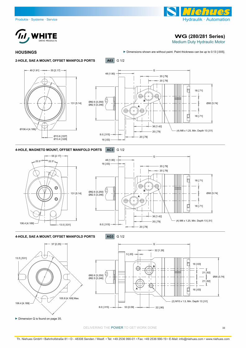
Medium Duty Hydraulic MotorWG (280/281 Series)
33DELIVERING THE POWER TO GET WORK DONE
HOUSINGS
Dimension Q is found on page 35.
A
B
A
BØ82.6 [3.250]Ø82.5 [3.246]
Q
Ø95 [3.74]
18 [.71]
18 [.71]
8.0 [.315]
16 [.63]
36 [1.42]
20 [.79]
20 [.79]
48 [1.90]
20 [.79]
20 [.79]
131 [5.14]
131 [5.14]
Ø106.4 [4.189]
55 [2.17]49 [1.91]
Ø13.6 [.537]Ø13.4 [.529]
Ø82.6 [3.250]Ø82.5 [3.246]
Q
Ø95 [3.74]
18 [.71]
18 [.71]
8.0 [.315]
16 [.63]
36 [1.42]
20 [.79]
20 [.79]
48 [1.90]
20 [.79]
20 [.79]
55 [2.17]
106.4 [4.189] 13.5 [.531]
22.5° 22.5°
Ø82.6 [3.250]Ø82.5 [3.246]
Q
Ø95 [3.74]
16 [.63]
16 [.63]
21 [.82]
21 [.82]
8.0 [.315]
32 [1.26]5 [.20]
53 [2.09] 22 [.90]
(2) M10 x 1.5, Min. Depth 13 [.51]
A
B
105.9 [4.169] Max.
57 [2.25]
106.4 [4.189]
13.5 [.531]
(4) M8 x 1.25, Min. Depth 13 [.51]
(4) M8 x 1.25, Min. Depth 13 [.51]
4-HOLE, MAGNETO MOUNT, OFFSET MANIFOLD PORTS AC3 G 1/2
A63 G 1/22-HOLE, SAE A MOUNT, OFFSET MANIFOLD PORTS
4-HOLE, SAE A MOUNT, OFFSET MANIFOLD PORTS AG3 G 1/2
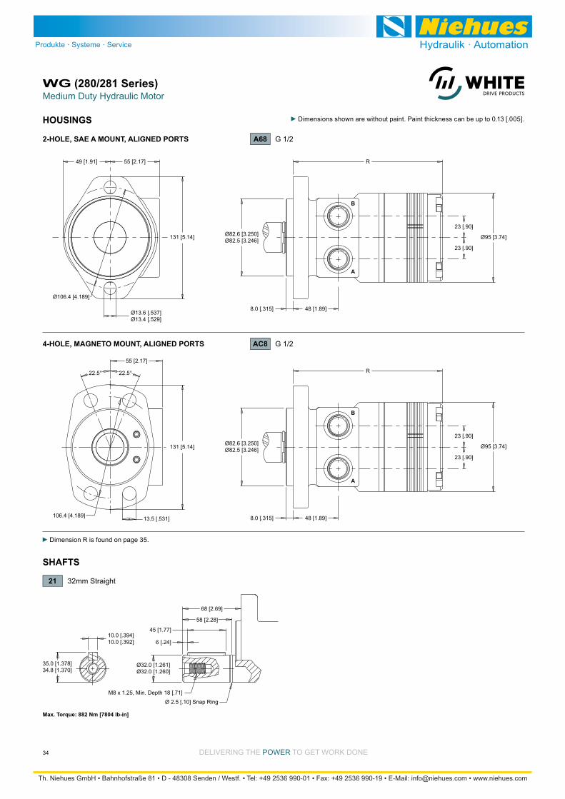
Medium Duty Hydraulic MotorWG (280/281 Series)
34 DELIVERING THE POWER TO GET WORK DONE
HOUSINGS
Dimension R is found on page 35.
SHAFTS
A
B
Ø82.6 [3.250]Ø82.5 [3.246]
R
Ø95 [3.74]
23 [.90]
23 [.90]
8.0 [.315] 48 [1.89]
A
B
131 [5.14]
131 [5.14]
Ø106.4 [4.189]
55 [2.17]49 [1.91]
Ø13.6 [.537]Ø13.4 [.529]
Ø82.6 [3.250]Ø82.5 [3.246]
R
Ø95 [3.74]
23 [.90]
23 [.90]
8.0 [.315] 48 [1.89]
55 [2.17]
106.4 [4.189] 13.5 [.531]
22.5° 22.5°
4-HOLE, MAGNETO MOUNT, ALIGNED PORTS AC8 G 1/2
A68 G 1/22-HOLE, SAE A MOUNT, ALIGNED PORTS
6 [.24]
45 [1.77]10.0 [.394]10.0 [.392]
35.0 [1.378]34.8 [1.370]
Ø32.0 [1.261]Ø32.0 [1.260]
68 [2.69]
M8 x 1.25, Min. Depth 18 [.71]
Ø 2.5 [.10] Snap Ring
58 [2.28]
Max. Torque: 882 Nm [7804 lb-in]
21 32mm Straight
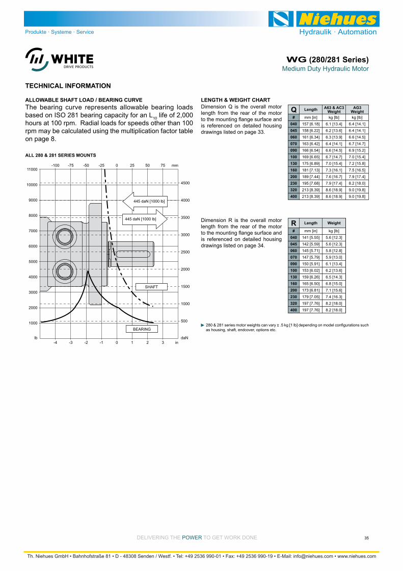
Medium Duty Hydraulic MotorWG (280/281 Series)
35DELIVERING THE POWER TO GET WORK DONE
LENGTH & WEIGHT CHARTDimension Q is the overall motor length from the rear of the motor
is referenced on detailed housing drawings listed on page 33.
A63 & AC3 AG3 Weight Weight Q
#040045060070090100130160200230320400
kg [lb]
6.4 [14.1]
6.4 [14.1]
6.6 [14.5]
6.7 [14.7]
6.9 [15.2]
7.0 [15.4]
7.2 [15.8]
7.5 [16.5]
7.9 [17.4]
8.2 [18.0]
9.0 [19.8]
9.0 [19.8]
mm [in]
157 [6.18]
158 [6.22]
161 [6.34]
163 [6.42]
166 [6.54]
169 [6.65]
175 [6.89]
181 [7.13]
189 [7.44]
195 [7.68]
213 [8.39]
213 [8.39]
kg [lb]
6.1 [13.4]
6.2 [13.6]
6.3 [13.9]
6.4 [14.1]
6.6 [14.5]
6.7 [14.7]
7.0 [15.4]
7.3 [16.1]
7.6 [16.7]
7.9 [17.4]
8.6 [18.9]
8.6 [18.9]
LengthThe bearing curve represents allowable bearing loads based on ISO 281 bearing capacity for an L10 life of 2,000 hours at 100 rpm. Radial loads for speeds other than 100 rpm may be calculated using the multiplication factor table on page 8.
ALLOWABLE SHAFT LOAD / BEARING CURVE
TECHNICAL INFORMATION
Dimension R is the overall motor length from the rear of the motor
is referenced on detailed housing drawings listed on page 34.
as housing, shaft, endcover, options etc.
3000
8000
ALL 280 & 281 SERIES MOUNTS
7000
6000
5000
4000
lb
2000
1000
1000
3500
9000 4000
10000 4500
11000
3000
2500
2000
1500
daN
500
2 in3-4 10-3 -1-2
50 mm75-100 250-75 -25-50
445 daN [1000 lb]
445 daN [1000 lb]
SHAFT
BEARING
#040045060070090100130160200230320400
mm [in]
141 [5.55]
142 [5.59]
145 [5.71]
147 [5.79]
150 [5.91]
153 [6.02]
159 [6.26]
165 [6.50]
173 [6.81]
179 [7.05]
197 [7.76]
197 [7.76]
kg [lb]
5.6 [12.3]
5.6 [12.3]
5.8 [12.8]
5.9 [13.0]
6.1 [13.4]
6.2 [13.6]
6.5 [14.3]
6.8 [15.0]
7.1 [15.6]
7.4 [16.3]
8.2 [18.0]
8.2 [18.0]
Length WeightR
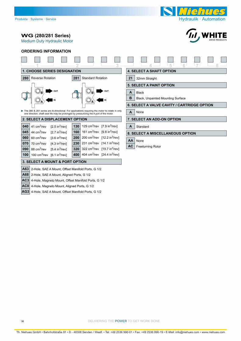
Medium Duty Hydraulic MotorWG (280/281 Series)
36 DELIVERING THE POWER TO GET WORK DONE
ORDERING INFORMATION
1 2 3 4 5 6 7 8
41 cm3/rev [2.5 in3/rev]
44 cm3/rev [2.7 in3/rev]
60 cm3/rev [3.6 in3/rev]
70 cm3/rev [4.3 in3/rev]
88 cm3/rev [5.4 in3/rev]
100 cm3/rev [6.1 in3/rev]
Reverse Rotation Standard Rotation
The 280 & 281 series are bi-directional. For applications requiring the motor to rotate in only one direction, shaft seal life may be prolonged by pressurizing the A port of the motor.
129 cm3/rev [7.9 in3/rev]
161 cm3/rev [9.8 in3/rev]
200 cm3/rev [12.2 in3/rev]
231 cm3/rev [14.1 in3/rev]
322 cm3/rev [19.7 in3/rev]
404 cm3/rev [24.4 in3/rev]
2-Hole, SAE A Mount, Offset Manifold Ports, G 1/2
2-Hole, SAE A Mount, Aligned Ports, G 1/2
4-Hole, Magneto Mount, Offset Manifold Ports, G 1/2
4-Hole, Magneto Mount, Aligned Ports, G 1/2
4-Hole, SAE A Mount, Offset Manifold Ports, G 1/2
32mm Straight
Black
Black, Unpainted Mounting Surface
Standard
None
Freeturning Rotor
None
280
1. CHOOSE SERIES DESIGNATION
2. SELECT A DISPLACEMENT OPTION
040045060070090100
130160200230320400
3. SELECT A MOUNT & PORT OPTION
A63A68AC3AC8AG3
4. SELECT A SHAFT OPTION
21
5. SELECT A PAINT OPTION
AB
6. SELECT A VALVE CAVITY / CARTRIDGE OPTION
7. SELECT AN ADD-ON OPTION
A
8. SELECT A MISCELLANEOUS OPTION
AAAC
281
A
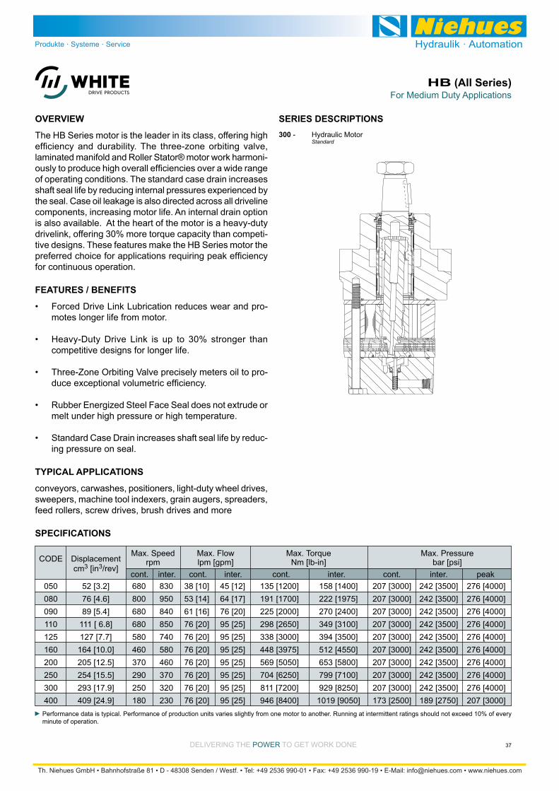
DELIVERING THE POWER TO GET WORK DONE
For Medium Duty ApplicationsHB (All Series)
37
SPECIFICATIONS
The HB Series motor is the leader in its class, offering high
-
of operating conditions. The standard case drain increases shaft seal life by reducing internal pressures experienced by
components, increasing motor life. An internal drain option is also available. At the heart of the motor is a heavy-duty
-
for continuous operation.
OVERVIEW
-motes longer life from motor.
competitive designs for longer life.
Three-Zone Orbiting Valve precisely meters oil to pro-
Rubber Energized Steel Face Seal does not extrude or melt under high pressure or high temperature.
Standard Case Drain increases shaft seal life by reduc-ing pressure on seal.
FEATURES / BENEFITS
SERIES DESCRIPTIONS
Performance data is typical. Performance of production units varies slightly from one motor to another. Running at intermittent ratings should not exceed 10% of every minute of operation.
conveyors, carwashes, positioners, light-duty wheel drives, sweepers, machine tool indexers, grain augers, spreaders, feed rollers, screw drives, brush drives and more
TYPICAL APPLICATIONS
Max. Speed Max. Flow Max. Torque Max. Pressure rpm lpm [gpm] Nm [lb-in] bar [psi]
050 52 [3.2] 680 830 38 [10] 45 [12] 135 [1200] 158 [1400] 207 [3000] 242 [3500] 276 [4000] 080 76 [4.6] 800 950 53 [14] 64 [17] 191 [1700] 222 [1975] 207 [3000] 242 [3500] 276 [4000] 090 89 [5.4] 680 840 61 [16] 76 [20] 225 [2000] 270 [2400] 207 [3000] 242 [3500] 276 [4000] 110 111 [ 6.8] 680 850 76 [20] 95 [25] 298 [2650] 349 [3100] 207 [3000] 242 [3500] 276 [4000] 125 127 [7.7] 580 740 76 [20] 95 [25] 338 [3000] 394 [3500] 207 [3000] 242 [3500] 276 [4000] 160 164 [10.0] 460 580 76 [20] 95 [25] 448 [3975] 512 [4550] 207 [3000] 242 [3500] 276 [4000] 200 205 [12.5] 370 460 76 [20] 95 [25] 569 [5050] 653 [5800] 207 [3000] 242 [3500] 276 [4000] 250 254 [15.5] 290 370 76 [20] 95 [25] 704 [6250] 799 [7100] 207 [3000] 242 [3500] 276 [4000] 300 293 [17.9] 250 320 76 [20] 95 [25] 811 [7200] 929 [8250] 207 [3000] 242 [3500] 276 [4000] 400 409 [24.9] 180 230 76 [20] 95 [25] 946 [8400] 1019 [9050] 173 [2500] 189 [2750] 207 [3000]
CODE Displacement cm3 [in3/rev] cont. inter. cont. inter. cont. inter. cont. inter. peak
300 - Hydraulic Motor Standard

DELIVERING THE POWER TO GET WORK DONE
For Medium Duty ApplicationsHB (All Series)
38
DISPLACEMENT PERFORMANCE
36
72
142
288
31
69
140
286
26
65
135
285
431
577
21
63
133
284
427
572
699
847
9
33
122
265
416
568
683
825
32
102
245
396
543
665
798
9
77
211
347
488
634
770
57
189
321
463
604
[66]
[77]
[75]
[68]
7
9
9
8
[158]
[164]
[164]
[164]
18
19
19
19
[314]
[335]
[342]
[340]
[319]
[304]
38
38
39
38
36
34
[447]
[505]
[521]
[507]
[492]
[467]
[451]
[427]
51
57
59
57
56
53
51
48
[587]
[631]
[690]
[688]
[669]
[646]
[628]
[606]
66
71
78
78
76
73
71
68
[772]
[840]
[872]
[859]
[841]
[810]
[781]
87
95
99
97
95
92
88
[866]
[964]
[993]
[1009]
[1001]
[978]
[980]
98
109
112
114
113
111
111
[1086]
[1145]
[1182]
[1183]
[1174]
123
129
134
134
133
Torque - Nm [lb-in], Speed rpm
Flow
- lp
m [g
pm]
17 [250] 35 [500] 69 [1000] 104 [1500] 138 [2000] 173 [2500] 207 [3000] 242 [3500]
14 [127] 29 [255] 58 [510] 86 [764] 115 [1019] 144 [1274] 173 [1529] 202 [1783]
Theoretical Torque - Nm [lb-in]
Max
.In
ter.
Max
.C
ont.
050
2 [0.5]
4 [1]
8 [2]
15 [4]
23 [6]
30 [8]
38 [10]
45 [12]
37
73
145
289
434
578
722
867
Theoretical rpm
Overall Efficiency - 70 - 100% 40 - 69% 0 - 39%
Intermittent Ratings - 10% of Operation
Displacement tested at 54°C [129°F] with an oil viscosity of 46cSt [213 SUS]
Max. Cont. Max. Inter.Pressure - bar [psi]
52 cm3 [3.2 in3] / rev
mm [in]
RotorWidth
8.0[.316]
25
50
100
200
301
401
24
50
100
200
300
400
502
602
690
21
43
99
199
297
398
500
601
689
18
43
92
191
295
390
499
600
688
17
34
87
181
284
384
498
597
658
11
32
79
174
271
372
485
540
644
11
32
78
160
253
346
443
526
631
9
31
77
154
245
339
433
510
613
[127]
[140]
[139]
[127]
[113]
[91]
14
16
16
14
13
10
[262]
[286]
[280]
[275]
[262]
[243]
[212]
[177]
[127]
30
32
32
31
30
27
24
20
14
[543]
[559]
[563]
[572]
[557]
[536]
[511]
[482]
[445]
61
63
64
65
63
61
58
54
50
[806]
[839]
[857]
[872]
[853]
[826]
[790]
[767]
[741]
91
95
97
99
96
93
89
87
84
[1062]
[1099]
[1139]
[1155]
[1149]
[1125]
[1087]
[1060]
[1098]
120
124
129
131
130
127
123
120
124
[1285]
[1340]
[1390]
[1420]
[1420]
[1409]
[1379]
[1451]
[1369]
145
151
157
160
160
159
156
164
155
[1496]
[1579]
[1652]
[1643]
[1646]
[1654]
[1638]
[1711]
[1640]
169
178
187
186
186
187
185
193
185
[1693]
[1796]
[1865]
[1911]
[1930]
[1945]
[1883]
[2021]
[1918]
191
203
211
216
218
220
213
228
217
Torque - Nm [lb-in], Speed rpm
Flow
- lp
m [g
pm]
17 [250] 35 [500] 69 [1000] 104 [1500] 138 [2000] 173 [2500] 207 [3000] 242 [3500]
21 [183] 41 [366] 83 [732] 124 [1099] 166 [1465] 207 [1831] 248 [2197] 290 [2564]
Theoretical Torque - Nm [lb-in]
Max
.In
ter.
Max
.C
ont.
080
2 [0.5]
4 [1]
8 [2]
15 [4]
23 [6]
30 [8]
38 [10]
45 [12]
53 [14]
61 [16]
64 [17]
26
51
101
201
302
402
503
603
704
804
904
Theoretical rpm
Overall Efficiency - 70 - 100% 40 - 69% 0 - 39%
Intermittent Ratings - 10% of Operation
Displacement tested at 54°C [129°F] with an oil viscosity of 46cSt [213 SUS]
Max. Cont. Max. Inter.Pressure - bar [psi]
76 cm3 [4.6 in3] / rev
mm [in]
RotorWidth
11.7[.462]
Performance data is typical. Performance of production units varies slightly from one motor to another. Operating at maximum continuous pressure and maximum cont inuous f low simultaneously is not recommended. For additional information on product testing please refer to page 7.
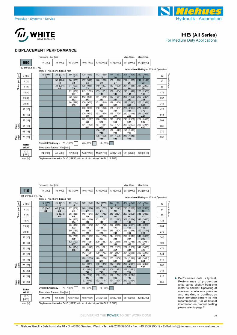
DELIVERING THE POWER TO GET WORK DONE
For Medium Duty ApplicationsHB (All Series)
39
16
33
16
33
67
14
31
64
134
202
269
339
407
475
11
27
59
126
196
267
336
406
473
542
609
678
746
813
847
9
21
49
117
186
258
327
397
466
536
603
677
743
810
844
8
19
46
110
177
247
315
386
451
523
593
661
735
803
835
6
18
44
104
167
267
304
368
441
510
580
645
714
783
828
5
16
43
104
163
229
292
360
426
492
561
627
[106]
[142]
12
16
[347]
[374]
[372]
39
42
42
[777]
[857]
[866]
[835]
[819]
[785]
[738]
[723]
[654]
88
97
98
94
93
89
83
82
74
[1199]
[1290]
[1313]
[1320]
[1312]
[1287]
[1232]
[1281]
[1143]
[1261]
[1059]
[944]
[824]
[762]
[678]
135
146
148
149
148
145
139
145
129
143
120
107
93
86
77
1609]
[1763]
[1782]
[1777]
[1775]
[1760]
[1718]
[1853]
[1621]
[1763]
[1586]
[1419]
[1393]
[1234]
[1171]
182
199
201
201
201
199
194
209
183
199
179
160
157
139
132
[1977]
[2179]
[2204]
[2223]
[2215]
[2204]
[2163]
[2578]
[2103]
[2224]
[2058]
[1918]
[1823]
[1744]
[1694]
223
246
249
251
250
249
244
291
238
251
233
217
206
197
191
[2420]
[2592]
[2629]
[2674]
[2671]
[2648]
[2617]
[2786]
[2539]
[2666]
[2510]
[2374]
[2271]
[2214]
[2154]
273
293
297
302
302
299
296
315
287
301
284
268
257
250
243
[2690]
[2916]
[3050]
[3083]
[3078]
[3114]
[3086]
[3031]
[3085]
[3213]
[3071]
[2896]
304
329
345
348
348
352
349
343
349
363
347
327
Torque - Nm [lb-in], Speed rpm
Flow
- lp
m [g
pm]
17 [250] 35 [500] 69 [1000] 104 [1500] 138 [2000] 173 [2500] 207 [3000] 242 [3500]
31 [271] 61 [541] 122 [1083] 184 [1624] 245 [2166] 306 [2707] 367 [3248] 428 [3790]
Theoretical Torque - Nm [lb-in]
Max
.In
ter.
Max
.C
ont.
110
2 [0.5]
4 [1]
8 [2]
15 [4]
23 [6]
30 [8]
38 [10]
45 [12]
53 [14]
61 [16]
68 [18]
76 [20]
83 [22]
91 [24]
95 [25]
17
34
68
136
204
272
340
408
476
544
612
680
748
816
850
Theoretical rpm
Overall Efficiency - 70 - 100% 40 - 69% 0 - 39%
Intermittent Ratings - 10% of Operation
Displacement tested at 54°C [129°F] with an oil viscosity of 46cSt [213 SUS]
Max. Cont. Max. Inter.Pressure - bar [psi]
111 cm3 [6.8 in3] / rev
mm [in]
RotorWidth
17.3[.681]
DISPLACEMENT PERFORMANCE
21 19
41
84
17
38
79
167
252
339
15
34
73
158
243
331
416
505
590
677
13
30
67
149
233
317
403
490
578
660
748
835
10
27
66
143
227
309
391
475
558
644
729
819
7
26
60
141
222
301
381
462
544
629
719
806
5
23
59
135
218
300
370
448
530
610
[106]12 [231]
[264]
[291]
26
30
33
[609]
[605]
[629]
[636]
[633]
[598]
69
68
71
72
72
68
[889]
[947]
[958]
[1003]
[995]
[960]
[959]
[961]
[1287]
[1190]
100
107
108
113
112
109
108
109
145
134
[1259]
[1296]
[1323]
[1351]
[1340]
[1340]
[1328]
[1356]
[1678]
[1654]
[1201]
[1205]
142
146
149
153
151
151
150
153
190
187
136
136
[1537]
[1596]
[1620]
[1664]
[1654]
[1660]
[1667]
[1728]
[1886]
[1701]
[1675]
[1536]
174
180
183
188
187
188
188
195
213
192
189
174
[1826]
[1875]
[1956]
[1990]
[1996]
[2012]
[2024]
[2049]
[2135]
[2007]
[2122]
[1916]
206
212
221
225
226
227
229
232
241
227
240
216
[2049]
[2142]
[2223]
[2300]
[2304]
[2326]
[2393]
[2398]
[2495]
[2384]
232
242
251
260
260
263
270
271
282
269
Torque - Nm [lb-in], Speed rpm
Flow
- lp
m [g
pm]
17 [250] 35 [500] 69 [1000] 104 [1500] 138 [2000] 173 [2500] 207 [3000] 242 [3500]
24 [215] 49 [430] 97 [860] 146 [1290] 194 [1720] 243 [2150] 291 [2580] 340 [3010]
Theoretical Torque - Nm [lb-in]
Max
.In
ter.
Max
.C
ont.
090
2 [0.5]
4 [1]
8 [2]
15 [4]
23 [6]
30 [8]
38 [10]
45 [12]
53 [14]
61 [16]
68 [18]
76 [20]
22
43
86
172
257
343
428
514
599
685
770
856
Theoretical rpm
Overall Efficiency - 70 - 100% 40 - 69% 0 - 39%
Intermittent Ratings - 10% of Operation
Displacement tested at 54°C [129°F] with an oil viscosity of 46cSt [213 SUS]
Max. Cont. Max. Inter.Pressure - bar [psi]
89 cm3 [5.4 in3] / rev
mm [in]
RotorWidth
13.7[.541]
Performance data is typical. Performance of production units varies slightly from one motor to another. Operating at maximum continuous pressure and maximum cont inuous f low simultaneously is not recommended. For additional information on product testing please refer to page 7.
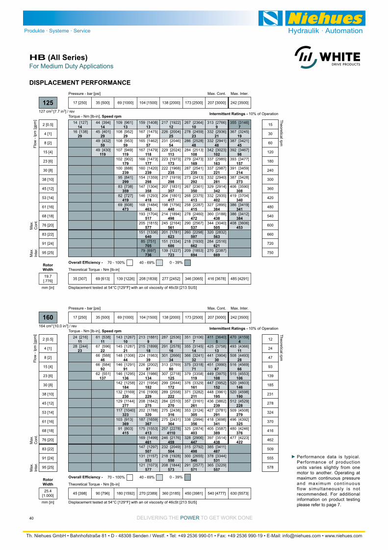
DELIVERING THE POWER TO GET WORK DONE
For Medium Duty ApplicationsHB (All Series)
40
11
23
11
22
46
92
137
10
21
44
91
136
184
230
277
323
369
415
9
18
39
87
134
182
229
275
320
367
413
461
507
553
577
8
16
34
80
125
172
222
270
316
364
4110
459
504
550
573
7
14
32
71
119
161
211
261
305
356
403
447
498
546
571
5
13
30
67
108
152
195
239
291
341
389
438
487
531
557
4
11
28
66
106
146
190
228
279
325
376
422
[216]
[244]
24
28
[538]
[596]
[588]
[584]
[551]
61
67
66
66
62
[1267]
[1287]
[1306]
[1291]
[1295]
[1258]
[1169]
[1144]
[1040]
[913]
[803]
143
145
148
146
146
142
132
129
117
103
91
[1881]
[1899]
[1983]
[2002]
[1986]
[1954]
[1909]
[1842]
[1788]
[1659]
[1553]
[1499]
[1297]
[1157]
[1073]
213
215
224
226
224
221
216
208
202
187
175
169
147
131
121
[2536]
[2578]
[2666]
[2769]
[2718]
[2644]
[2558]
[2510]
[2438]
[2431]
[2278]
[2176]
[2049]
[1928]
[1844]
287
291
301
313
307
299
289
284
275
275
257
246
232
218
208
[3106]
[3145]
[3241]
[3318]
[3358]
[3329]
[3282]
[3161]
[3124]
[2994]
[2874]
[2906]
[2792]
[2655]
[2577]
351
355
366
375
379
376
371
357
353
338
325
328
315
300
291
[3640]
[3758]
[3904]
[3990]
[3975]
[3952]
[3961]
[3862]
[3781]
[3698]
[3587]
[3514]
[3411]
[3344]
[3229]
411
425
441
451
449
447
448
436
427
418
405
397
385
378
365
[4159]
[4366]
[4493]
[4569]
[4553]
[4603]
[4598]
[4529]
[4508]
[4392]
[4246]
[4223]
470
493
508
516
515
520
520
512
509
496
480
477
Torque - Nm [lb-in], Speed rpm
Flow
- lp
m [g
pm]
17 [250] 35 [500] 69 [1000] 104 [1500] 138 [2000] 173 [2500] 207 [3000] 242 [3500]
45 [398] 90 [796] 180 [1592] 270 [2389] 360 [3185] 450 [3981] 540 [4777] 630 [5573]
Theoretical Torque - Nm [lb-in]
Max
.In
ter.
Max
.C
ont.
160
2 [0.5]
4 [1]
8 [2]
15 [4]
23 [6]
30 [8]
38 [10]
45 [12]
53 [14]
61 [16]
68 [18]
76 [20]
83 [22]
91 [24]
95 [25]
12
24
47
93
139
185
231
278
324
370
416
462
509
555
578
Theoretical rpm
Overall Efficiency - 70 - 100% 40 - 69% 0 - 39%
Intermittent Ratings - 10% of Operation
Displacement tested at 54°C [129°F] with an oil viscosity of 46cSt [213 SUS]
Max. Cont. Max. Inter.Pressure - bar [psi]
164 cm3 [10.0 in3] / rev
mm [in]
RotorWidth
25.4[1.000]
DISPLACEMENT PERFORMANCE
14
29
14
29
59
119
13
29
59
119
179
239
299
359
419
473
13
27
57
118
177
239
298
358
418
463
517
577
640
705
736
12
25
54
113
173
235
298
357
417
440
498
561
623
686
723
10
23
48
108
169
235
292
350
413
415
472
537
597
662
694
9
21
48
102
163
221
281
342
402
384
438
505
563
621
669
7
19
45
98
157
214
273
308
340
341
384
453
[127]
[138]
14
16
[394]
[401]
[432]
[430]
44
45
49
49
[961]
[952]
[953]
[949]
[902]
[888]
[841]
[738]
[727]
[608]
109
108
108
107
102
100
95
83
82
69
[1408]
[1475]
[1462]
[1479]
[1473]
[1420]
[1359]
[1304]
[1293]
[1484]
[1704]
[1815]
[1336]
[751]
[697]
159
167
165
167
166
160
154
147
146
168
193
205
151
85
79
[1922]
[2004]
[2046]
[2024]
[1973]
[1968]
[1919]
[1831]
[1801]
[1756]
[1894]
[2164]
[1781]
[1334]
[1227]
217
226
231
229
223
222
217
207
204
198
214
245
201
151
139
[2364]
[2459]
[2528]
[2513]
[2473]
[2541]
[2413]
[2361]
[2375]
[2287]
[2460]
[2567]
[2298]
[1930]
[1853]
267
278
286
284
279
287
273
267
268
258
278
290
260
218
209
[2766]
[2936]
[2941]
[3023]
[2985]
[2987]
[2940]
[2914]
[2935]
[2895]
[3188]
[3040]
[2832]
[2516]
[2387]
313
332
332
342
337
337
332
329
332
327
360
344
320
284
270
[3146]
[3245]
[3421]
[3467]
[3477]
[3459]
[3428]
[3590]
[3704]
[3419]
[3412]
[3606]
355
367
387
392
393
391
387
406
419
386
386
408
Torque - Nm [lb-in], Speed rpm
Flow
- lp
m [g
pm]
17 [250] 35 [500] 69 [1000] 104 [1500] 138 [2000] 173 [2500] 207 [3000] 242 [3500]
35 [307] 69 [613] 139 [1226] 208 [1839] 277 [2452] 346 [3065] 416 [3678] 485 [4291]
Theoretical Torque - Nm [lb-in]
Max
.In
ter.
Max
.C
ont.
125
2 [0.5]
4 [1]
8 [2]
15 [4]
23 [6]
30 [8]
38 [10]
45 [12]
53 [14]
61 [16]
68 [18]
76 [20]
83 [22]
91 [24]
95 [25]
15
30
60
120
180
240
300
360
420
480
540
600
660
720
750
Theoretical rpm
Overall Efficiency - 70 - 100% 40 - 69% 0 - 39%
Intermittent Ratings - 10% of Operation
Displacement tested at 54°C [129°F] with an oil viscosity of 46cSt [213 SUS]
Max. Cont. Max. Inter.Pressure - bar [psi]
127 cm3 [7.7 in3] / rev
mm [in]
RotorWidth
19.7[.776]
Performance data is typical. Performance of production units varies slightly from one motor to another. Operating at maximum continuous pressure and maximum cont inuous f low simultaneously is not recommended. For additional information on product testing please refer to page 7.
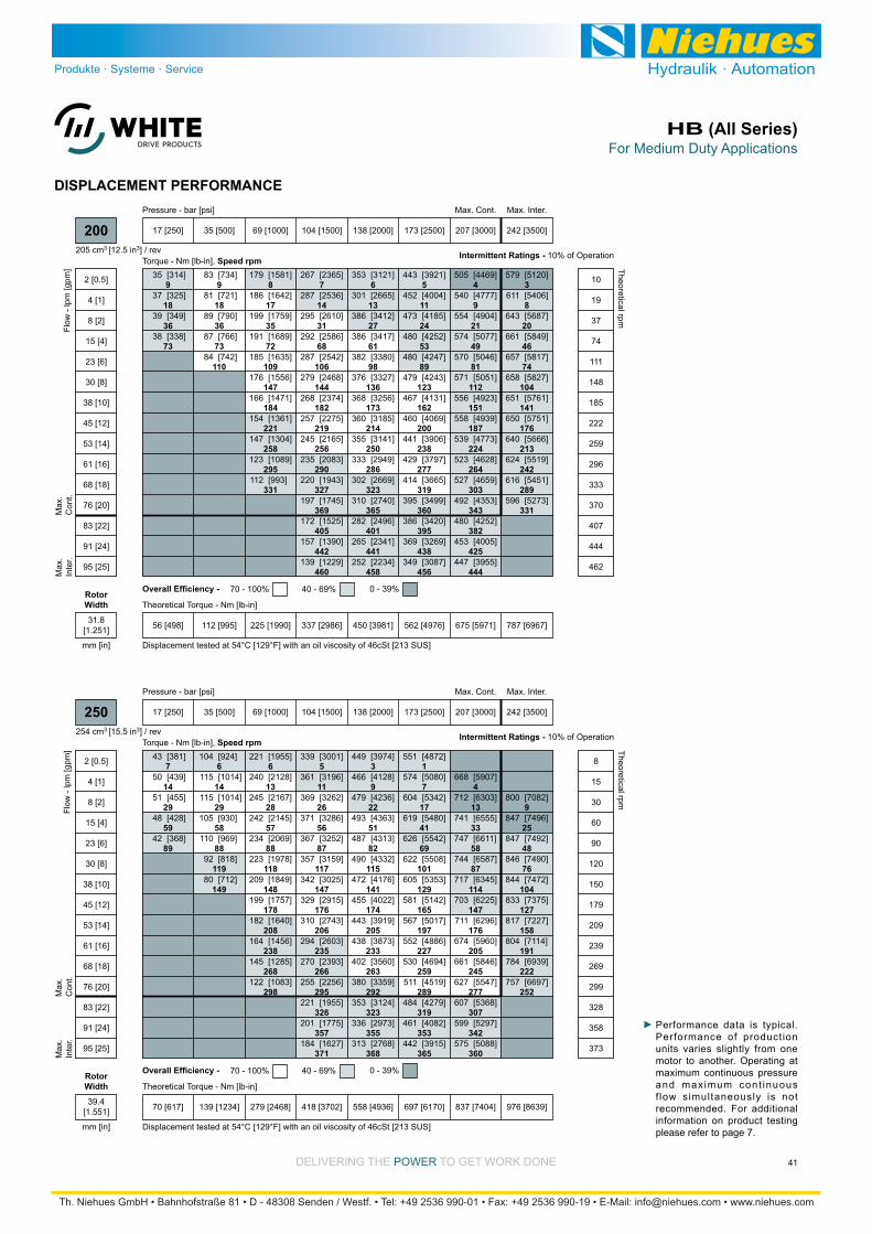
DELIVERING THE POWER TO GET WORK DONE
For Medium Duty ApplicationsHB (All Series)
41
7
14
29
59
89
6
14
29
58
88
119
149
6
13
28
57
88
118
148
178
208
238
268
298
5
11
26
56
87
117
147
176
206
235
266
295
326
357
371
3
9
22
51
82
115
141
174
205
233
263
292
323
355
368
1
7
17
41
69
101
129
165
197
227
259
289
319
353
365
4
13
33
58
87
114
147
176
205
245
277
307
342
360
9
25
48
76
104
127
158
191
222
252
[381]
[439]
[455]
[428]
[368]
43
50
51
48
42
[924]
[1014]
[1014]
[930]
[969]
[818]
[712]
104
115
115
105
110
92
80
[1955]
[2128]
[2167]
[2145]
[2069]
[1978]
[1849]
[1757]
[1640]
[1456]
[1285]
[1083]
221
240
245
242
234
223
209
199
182
164
145
122
[3001]
[3196]
[3262]
[3286]
[3252]
[3159]
[3025]
[2915]
[2743]
[2603]
[2393]
[2256]
[1955]
[1775]
[1627]
339
361
369
371
367
357
342
329
310
294
270
255
221
201
184
[3974]
[4128]
[4236]
[4363]
[4313]
[4332]
[4176]
[4022]
[3919]
[3873]
[3560]
[3359]
[3124]
[2973]
[2768]
449
466
479
493
487
490
472
455
443
438
402
380
353
336
313
[4872]
[5080]
[5342]
[5480]
[5542]
[5508]
[5353]
[5142]
[5017]
[4886]
[4694]
[4519]
[4279]
[4082]
[3915]
551
574
604
619
626
622
605
581
567
552
530
511
484
461
442
[5907]
[6303]
[6555]
[6611]
[6587]
[6345]
[6225]
[6296]
[5960]
[5846]
[5547]
[5368]
[5297]
[5088]
668
712
741
747
744
717
703
711
674
661
627
607
599
575
[7082]
[7496]
[7492]
[7490]
[7472]
[7375]
[7227]
[7114]
[6939]
[6697]
800
847
847
846
844
833
817
804
784
757
Torque - Nm [lb-in], Speed rpm
Flow
- lp
m [g
pm]
17 [250] 35 [500] 69 [1000] 104 [1500] 138 [2000] 173 [2500] 207 [3000] 242 [3500]
70 [617] 139 [1234] 279 [2468] 418 [3702] 558 [4936] 697 [6170] 837 [7404] 976 [8639]
Theoretical Torque - Nm [lb-in]
Max
.In
ter.
Max
.C
ont.
250
2 [0.5]
4 [1]
8 [2]
15 [4]
23 [6]
30 [8]
38 [10]
45 [12]
53 [14]
61 [16]
68 [18]
76 [20]
83 [22]
91 [24]
95 [25]
8
15
30
60
90
120
150
179
209
239
269
299
328
358
373
Theoretical rpm
Overall Efficiency - 70 - 100% 40 - 69% 0 - 39%
Intermittent Ratings - 10% of Operation
Displacement tested at 54°C [129°F] with an oil viscosity of 46cSt [213 SUS]
Max. Cont. Max. Inter.Pressure - bar [psi]
254 cm3 [15.5 in3] / rev
mm [in]
RotorWidth
39.4[1.551]
DISPLACEMENT PERFORMANCE
9
18
36
73
9
18
36
73
110
8
17
35
72
109
147
184
221
258
295
331
7
14
31
68
106
144
182
219
256
290
327
369
405
442
460
6
13
27
61
98
136
173
214
250
286
323
365
401
441
458
5
11
24
53
89
123
162
200
238
277
319
360
395
438
456
4
9
21
49
81
112
151
187
224
264
303
343
382
425
444
3
8
20
46
74
104
141
176
213
242
289
331
[314]
[325]
[349]
[338]
35
37
39
38
[734]
[721]
[790]
[766]
[742]
83
81
89
87
84
[1581]
[1642]
[1759]
[1689]
[1635]
[1556]
[1471]
[1361]
[1304]
[1089]
[993]
179
186
199
191
185
176
166
154
147
123
112
[2365]
[2536]
[2610]
[2586]
[2542]
[2468]
[2374]
[2275]
[2165]
[2083]
[1943]
[1745]
[1525]
[1390]
[1229]
267
287
295
292
287
279
268
257
245
235
220
197
172
157
139
[3121]
[2665]
[3412]
[3417]
[3380]
[3327]
[3256]
[3185]
[3141]
[2949]
[2669]
[2740]
[2496]
[2341]
[2234]
353
301
386
386
382
376
368
360
355
333
302
310
282
265
252
[3921]
[4004]
[4185]
[4252]
[4247]
[4243]
[4131]
[4069]
[3906]
[3797]
[3665]
[3499]
[3420]
[3269]
[3087]
443
452
473
480
480
479
467
460
441
429
414
395
386
369
349
[4469]
[4777]
[4904]
[5077]
[5046]
[5051]
[4923]
[4939]
[4773]
[4628]
[4659]
[4353]
[4252]
[4005]
[3955]
505
540
554
574
570
571
556
558
539
523
527
492
480
453
447
[5120]
[5406]
[5687]
[5849]
[5817]
[5827]
[5761]
[5751]
[5666]
[5519]
[5451]
[5273]
579
611
643
661
657
658
651
650
640
624
616
596
Torque - Nm [lb-in], Speed rpm
Flow
- lp
m [g
pm]
17 [250] 35 [500] 69 [1000] 104 [1500] 138 [2000] 173 [2500] 207 [3000] 242 [3500]
56 [498] 112 [995] 225 [1990] 337 [2986] 450 [3981] 562 [4976] 675 [5971] 787 [6967]
Theoretical Torque - Nm [lb-in]
Max
.In
ter.
Max
.C
ont.
200
2 [0.5]
4 [1]
8 [2]
15 [4]
23 [6]
30 [8]
38 [10]
45 [12]
53 [14]
61 [16]
68 [18]
76 [20]
83 [22]
91 [24]
95 [25]
10
19
37
74
111
148
185
222
259
296
333
370
407
444
462
Theoretical rpm
Overall Efficiency - 70 - 100% 40 - 69% 0 - 39%
Intermittent Ratings - 10% of Operation
Displacement tested at 54°C [129°F] with an oil viscosity of 46cSt [213 SUS]
Max. Cont. Max. Inter.Pressure - bar [psi]
205 cm3 [12.5 in3] / rev
mm [in]
RotorWidth
31.8[1.251]
Performance data is typical. Performance of production units varies slightly from one motor to another. Operating at maximum continuous pressure and maximum cont inuous f low simultaneously is not recommended. For additional information on product testing please refer to page 7.
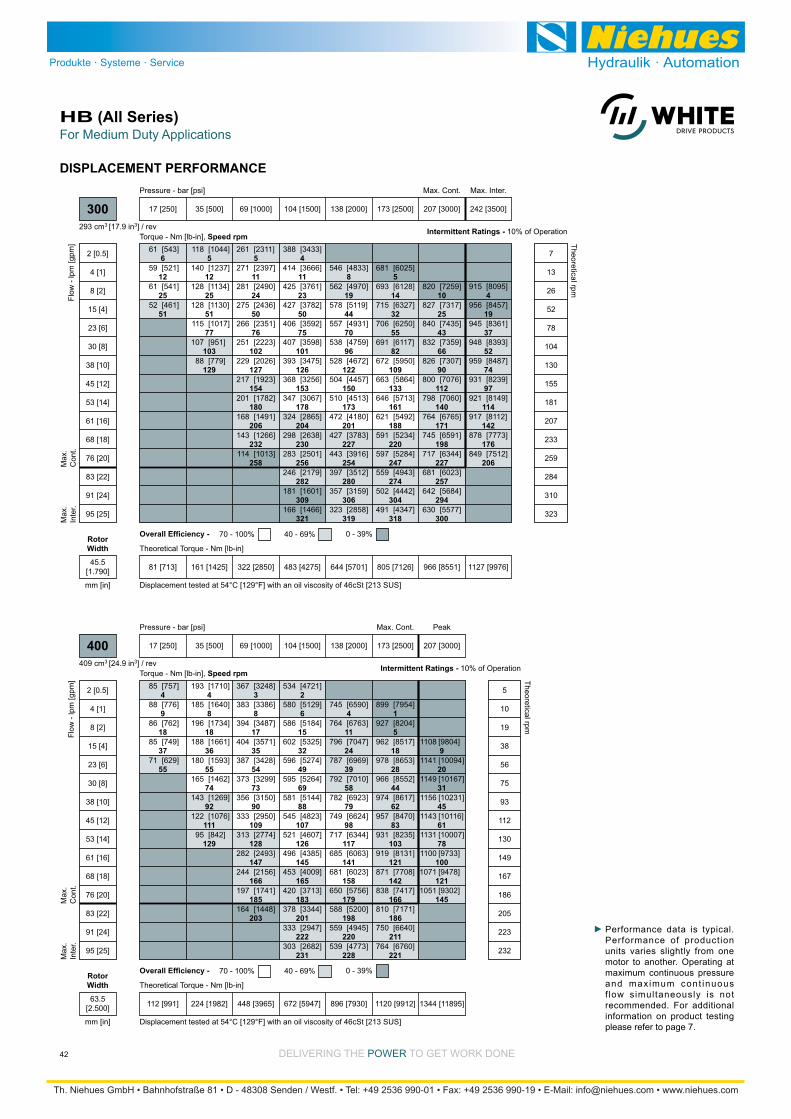
DELIVERING THE POWER TO GET WORK DONE
For Medium Duty ApplicationsHB (All Series)
42
DISPLACEMENT PERFORMANCE
6
12
25
51
5
12
25
51
77
103
129
5
11
24
50
76
102
127
154
180
206
232
258
4
11
23
50
75
101
126
153
178
204
230
256
282
309
321
8
19
44
70
96
122
150
173
201
227
254
280
306
319
5
14
32
55
82
109
133
161
188
220
247
274
304
318
10
25
43
66
90
112
140
171
198
227
257
294
300
4
19
37
52
74
97
114
142
176
206
[543]
[521]
[541]
[461]
61
59
61
52
[1044]
[1237]
[1134]
[1130]
[1017]
[951]
[779]
118
140
128
128
115
107
88
[2311]
[2397]
[2490]
[2436]
[2351]
[2223]
[2026]
[1923]
[1782]
[1491]
[1266]
[1013]
261
271
281
275
266
251
229
217
201
168
143
114
[3433]
[3666]
[3761]
[3782]
[3592]
[3598]
[3475]
[3256]
[3067]
[2865]
[2638]
[2501]
[2179]
[1601]
[1466]
388
414
425
427
406
407
393
368
347
324
298
283
246
181
166
[4833]
[4970]
[5119]
[4931]
[4759]
[4672]
[4457]
[4513]
[4180]
[3783]
[3916]
[3512]
[3159]
[2858]
546
562
578
557
538
528
504
510
472
427
443
397
357
323
[6025]
[6128]
[6327]
[6250]
[6117]
[5950]
[5864]
[5713]
[5492]
[5234]
[5284]
[4943]
[4442]
[4347]
681
693
715
706
691
672
663
646
621
591
597
559
502
491
[7259]
[7317]
[7435]
[7359]
[7307]
[7076]
[7060]
[6765]
[6591]
[6344]
[6023]
[5684]
[5577]
820
827
840
832
826
800
798
764
745
717
681
642
630
[8095]
[8457]
[8361]
[8393]
[8487]
[8239]
[8149]
[8112]
[7773]
[7512]
915
956
945
948
959
931
921
917
878
849
Torque - Nm [lb-in], Speed rpm
Flow
- lp
m [g
pm]
17 [250] 35 [500] 69 [1000] 104 [1500] 138 [2000] 173 [2500] 207 [3000] 242 [3500]
81 [713] 161 [1425] 322 [2850] 483 [4275] 644 [5701] 805 [7126] 966 [8551] 1127 [9976]
Theoretical Torque - Nm [lb-in]
Max
.In
ter.
Max
.C
ont.
300
2 [0.5]
4 [1]
8 [2]
15 [4]
23 [6]
30 [8]
38 [10]
45 [12]
53 [14]
61 [16]
68 [18]
76 [20]
83 [22]
91 [24]
95 [25]
7
13
26
52
78
104
130
155
181
207
233
259
284
310
323
Theoretical rpm
Overall Efficiency - 70 - 100% 40 - 69% 0 - 39%
Intermittent Ratings - 10% of Operation
Displacement tested at 54°C [129°F] with an oil viscosity of 46cSt [213 SUS]
Max. Cont. Max. Inter.Pressure - bar [psi]
293 cm3 [17.9 in3] / rev
mm [in]
RotorWidth
45.5[1.790]
4
9
18
37
55
4
8
18
36
55
74
92
111
129
3
8
17
35
54
73
90
109
128
147
166
185
203
2
6
15
32
49
69
88
107
126
145
165
183
201
222
231
4
11
24
39
58
79
98
117
141
158
179
198
220
228
1
5
18
28
44
62
83
103
121
142
166
186
211
221
9
20
31
45
61
78
100
121
145
[757]
[776]
[762]
[749]
[629]
85
88
86
85
71
[1710]
[1640]
[1734]
[1661]
[1593]
[1462]
[1269]
[1076]
[842]
193
185
196
188
180
165
143
122
95
[3248]
[3386]
[3487]
[3571]
[3428]
[3299]
[3150]
[2950]
[2774]
[2493]
[2156]
[1741]
[1448]
367
383
394
404
387
373
356
333
313
282
244
197
164
[4721]
[5129]
[5184]
[5325]
[5274]
[5264]
[5144]
[4823]
[4607]
[4385]
[4009]
[3713]
[3344]
[2947]
[2682]
534
580
586
602
596
595
581
545
521
496
453
420
378
333
303
[6590]
[6763]
[7047]
[6969]
[7010]
[6923]
[6624]
[6344]
[6063]
[6023]
[5756]
[5200]
[4945]
[4773]
745
764
796
787
792
782
749
717
685
681
650
588
559
539
[7954]
[8204]
[8517]
[8653]
[8552]
[8617]
[8470]
[8235]
[8131]
[7708]
[7417]
[7171]
[6640]
[6760]
899
927
962
978
966
974
957
931
919
871
838
810
750
764
[9804]
[10094]
[10167]
[10231]
[10116]
[10007]
[9733]
[9478]
[9302]
1108
1141
1149
1156
1143
1131
1100
1071
1051
Torque - Nm [lb-in], Speed rpm
Flow
- lp
m [g
pm]
17 [250] 35 [500] 69 [1000] 104 [1500] 138 [2000] 173 [2500] 207 [3000]
Pressure - bar [psi]
112 [991] 224 [1982] 448 [3965] 672 [5947] 896 [7930] 1120 [9912] 1344 [11895]
Theoretical Torque - Nm [lb-in]
Max
.In
ter.
Max
.C
ont.
400
2 [0.5]
4 [1]
8 [2]
15 [4]
23 [6]
30 [8]
38 [10]
45 [12]
53 [14]
61 [16]
68 [18]
76 [20]
83 [22]
91 [24]
95 [25]
5
10
19
38
56
75
93
112
130
149
167
186
205
223
232
Theoretical rpm
Overall Efficiency - 70 - 100% 40 - 69% 0 - 39%
Intermittent Ratings - 10% of Operation
Displacement tested at 54°C [129°F] with an oil viscosity of 46cSt [213 SUS]
Max. Cont. Peak
409 cm3 [24.9 in3] / rev
mm [in]
RotorWidth
63.5[2.500]
Performance data is typical. Performance of production units varies slightly from one motor to another. Operating at maximum continuous pressure and maximum cont inuous f low simultaneously is not recommended. For additional information on product testing please refer to page 7.
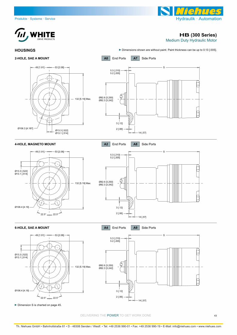
Medium Duty Hydraulic MotorHB (300 Series)
43DELIVERING THE POWER TO GET WORK DONE
HOUSINGS
Dimension S is charted on page 45.
132 [5.19] Max. Ø82.6 [3.250]Ø82.3 [3.242]
Ø106.4 [4.19]
53 [2.08]5.3 [.210]5.2 [.205]
49 [1.91]
Ø13.3 [.522]Ø13.1 [.514]
S
22.5° 22.5°
3 [.12]
2 [.06]14 [.57]
132 [5.19] Max. Ø82.6 [3.250]Ø82.3 [3.242]
Ø106.4 [4.19]
53 [2.08]5.3 [.210]5.2 [.205]
49 [1.91]
Ø13.3 [.522]Ø13.1 [.514]
S
22.5° 22.5°
3 [.12]
2 [.06]14 [.57]
132 [5.19] Max. Ø82.6 [3.250]Ø82.3 [3.242]
Ø106.3 [4.187]
53 [2.08]5.3 [.210]5.2 [.205]
49 [1.91]
Ø13.3 [.522]Ø13.1 [.514]
S
3 [.12]
2 [.06]14 [.57]
4-HOLE, MAGNETO MOUNT
6-HOLE, SAE A MOUNT
A7 Side Ports2-HOLE, SAE A MOUNT A0 End Ports
A8 Side PortsA2 End Ports
A9 Side PortsA4 End Ports

Medium Duty Hydraulic MotorHB (300 Series)
44 DELIVERING THE POWER TO GET WORK DONE
HOUSINGS
Dimensions S & T are charted on page 45. Dimension U is charted on page 46.
90 [3.56]79 [3.12] Max.
Ø82.6 [3.250]
(4) 3/8-16 UNC,Min. Depth 16 [.63]
96 [3.78] T
3 [.12]2 [.06]
132 [5.19] Max.
Ø82.6 [3.250]Ø82.3 [3.242]
Ø127.0 [4.999]Ø126.8 [4.994]
Ø147.6 [5.812]
41 [1.62]
138 [5.45] Max.
Ø13.3 [.522]Ø13.1 [.514]
U
45°
36 [1.42]3 [.10] Min.
45°
177 [6.96] Max. Ø101.6 [3.999]Ø101.4 [3.992]
Ø146 [5.75]51 [2.00]
60 [2.37] Max. 3.2 [.125]60 [2.37] Max.
Ø13.3 [.522]Ø13.1 [.514]
S
3 [.12]
2 [.06]
4-HOLE, SQUARE MOUNT
4-HOLE, WHEEL MOUNT
B7 Side Ports2-HOLE, SAE B MOUNT B0 End Ports
F8 Side PortsF2 End Ports
W8 Side PortsW2 End Ports

Medium Duty Hydraulic MotorHB (300 Series)
45DELIVERING THE POWER TO GET WORK DONE
TECHNICAL INFORMATION
3000
9000
8000
4-HOLE SQUARE MOUNTS
7000
6000
5000
4000
lb
2000
1000
1000
4000
3000
3500
2500
2000
1500
daN
500
2 in3-3 1-2 -1 0
mm75-75 5025-50 -25 0
445 daN [1000 lb]
445 daN [1000 lb]
SHAFT
BEARING
3000
8000
SAE A & B MOUNTS
7000
6000
5000
4000
lb
2000
1000
1000
3500
3000
2500
2000
1500
daN
500
3 in4-3 21-2 0-1
75 mm100-75 5025-50 0-25
445 daN [1000 lb]
445 daN [1000 lb]
SHAFT
BEARING
The bearing curve represents allowable bearing loads based on ISO 281 bearing capacity for an L10 life of 2,000 hours at 100 rpm. Radial loads for speeds other than 100 rpm may be calculated using the multiplication factor table on page 8.
ALLOWABLE SHAFT LOAD / BEARING CURVE LENGTH & WEIGHT CHARTDimension S is the overall motor length from the rear of the motor
is referenced on detailed housing drawings listed on pages 43 & 44.
Endcovers Endcovers on pg. 47 on pg. 48 WeightS
#050080090110125160200250300400
kg [lb]
8.8 [19.5]
9.1 [20.0]
9.2 [20.2]
9.4 [20.7]
9.5 [21.0]
9.8 [21.7]
10.2 [22.5]
10.6 [23.4]
11.0 [24.3]
12.0 [26.4]
mm [in]
177 [6.97]
181 [7.11]
183 [7.19]
186 [7.33]
189 [7.43]
194 [7.65]
201 [7.90]
208 [8.20]
214 [8.44]
233 [9.15]
mm [in]
195 [7.68]
199 [7.82]
201 [7.90]
204 [8.04]
207 [8.14]
212 [8.36]
219 [8.61]
226 [8.91]
232 [9.15]
251 [9.86]right for SAE B mount housings.
Dimension T is the overall motor length from the rear of the motor
is referenced on detailed housing drawings listed on page 44.
Endcovers Endcovers on pg. 47 on pg. 48 WeightT
#050080090110125160200250300400
kg [lb]
8.3 [18.4]
8.6 [18.9]
8.7 [19.1]
8.9 [19.6]
9.0 [19.9]
9.3 [20.6]
9.7 [21.4]
10.1 [22.3]
10.5 [23.2]
11.5 [25.3]
mm [in]
180 [7.09]
184 [7.23]
186 [7.31]
189 [7.45]
192 [7.55]
197 [7.77]
204 [8.02]
211 [8.32]
218 [8.56]
236 [9.27]
mm [in]
198 [7.80]
202 [7.94]
204 [8.02]
207 [8.16]
210 [8.26]
215 [8.48]
222 [8.73]
229 [9.03]
236 [9.27]
254 [9.98]
housing, shaft, endcover, options etc.
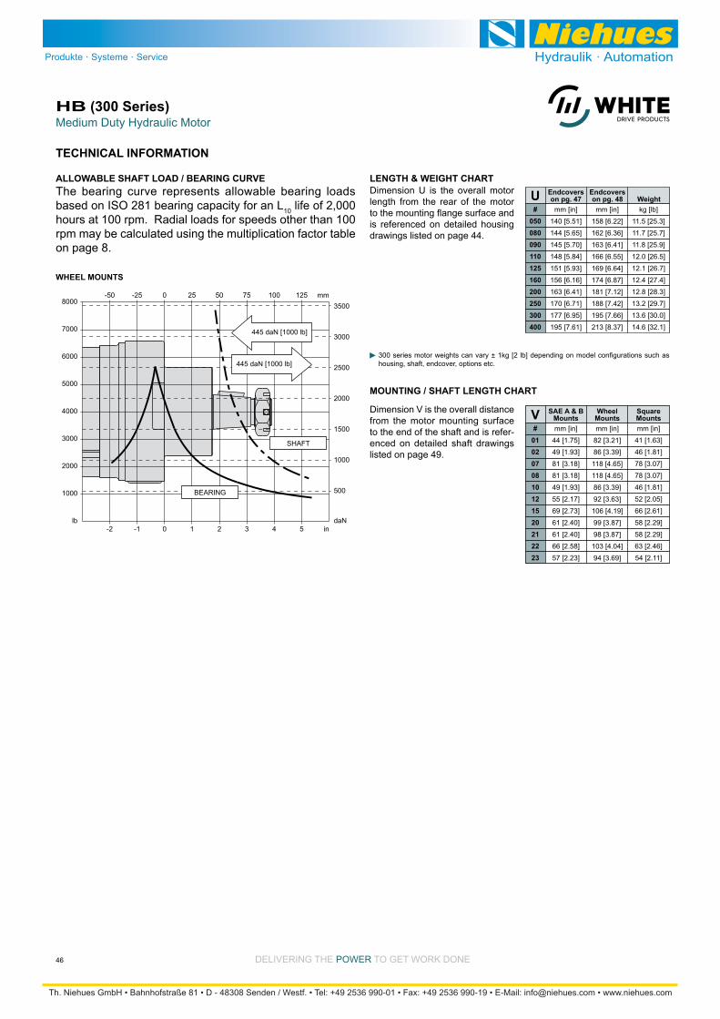
Medium Duty Hydraulic MotorHB (300 Series)
46 DELIVERING THE POWER TO GET WORK DONE
TECHNICAL INFORMATION
3000
8000
WHEEL MOUNTS
7000
6000
5000
4000
lb
2000
1000
1000
3500
3000
2500
2000
1500
daN
500
4 in5-2 32-1 10
100 mm125-50 7550-25 250
445 daN [1000 lb]
445 daN [1000 lb]
SHAFT
BEARING
LENGTH & WEIGHT CHARTDimension U is the overall motor length from the rear of the motor
is referenced on detailed housing drawings listed on page 44.
Endcovers Endcovers on pg. 47 on pg. 48 WeightU
#050080090110125160200250300400
kg [lb]
11.5 [25.3]
11.7 [25.7]
11.8 [25.9]
12.0 [26.5]
12.1 [26.7]
12.4 [27.4]
12.8 [28.3]
13.2 [29.7]
13.6 [30.0]
14.6 [32.1]
mm [in]
140 [5.51]
144 [5.65]
145 [5.70]
148 [5.84]
151 [5.93]
156 [6.16]
163 [6.41]
170 [6.71]
177 [6.95]
195 [7.61]
mm [in]
158 [6.22]
162 [6.36]
163 [6.41]
166 [6.55]
169 [6.64]
174 [6.87]
181 [7.12]
188 [7.42]
195 [7.66]
213 [8.37]
The bearing curve represents allowable bearing loads based on ISO 281 bearing capacity for an L10 life of 2,000 hours at 100 rpm. Radial loads for speeds other than 100 rpm may be calculated using the multiplication factor table on page 8.
ALLOWABLE SHAFT LOAD / BEARING CURVE
housing, shaft, endcover, options etc.
MOUNTING / SHAFT LENGTH CHART
Dimension V is the overall distance from the motor mounting surface to the end of the shaft and is refer-enced on detailed shaft drawings listed on page 49.
SAE A & BMounts
WheelMounts
SquareMountsV
#0102070810121520212223
mm [in]
41 [1.63]
46 [1.81]
78 [3.07]
78 [3.07]
46 [1.81]
52 [2.05]
66 [2.61]
58 [2.29]
58 [2.29]
63 [2.46]
54 [2.11]
mm [in]
44 [1.75]
49 [1.93]
81 [3.18]
81 [3.18]
49 [1.93]
55 [2.17]
69 [2.73]
61 [2.40]
61 [2.40]
66 [2.58]
57 [2.23]
mm [in]
82 [3.21]
86 [3.39]
118 [4.65]
118 [4.65]
86 [3.39]
92 [3.63]
106 [4.19]
99 [3.87]
98 [3.87]
103 [4.04]
94 [3.69]
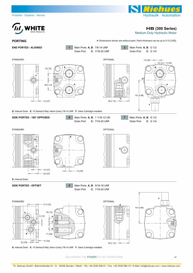
Medium Duty Hydraulic MotorHB (300 Series)
47DELIVERING THE POWER TO GET WORK DONE
PORTING
A
B
CC
A
B
A
B
CA
B
C
12 [.47]
12 [.47]13 [.50]
24 [.97]
A
B
C C
19 [.75]
28 [1.12]
31 [1.22]
22 [.85]13 [.52]
5 [.19]
18 [.72]
17 [.66]
D
D D
F
F
A
B
E29 [1.13]
E
29 [1.13]
D
101 [3.96]
101 [3.96]
14 [.55]5 [.20]
SIDE PORTED - 180° OPPOSED
SIDE PORTED - OFFSET
END PORTED - ALIGNED 1 Main Ports A, B: 7/8-14 UNFDrain Port C: 7/16-20 UNF
2 Main Ports A, B: G 1/2Drain Port C: G 1/4
6 Main Ports A, B: 1 1/16-12 UNDrain Port C: 7/16-20 UNF
5 Main Ports A, B: 9/16-18 UNFDrain Port C: 7/16-20 UNF
7 Main Ports A, B: G 1/2Drain Port C: G 1/4
STANDARD OPTIONAL
STANDARD
STANDARD
OPTIONAL
OPTIONAL
D: Internal Drain E: 10 Series/2-Way Valve Cavity 7/8-14 UNF F: Valve Cartridge Installed
D: Internal Drain E: 10 Series/2-Way Valve Cavity 7/8-14 UNF F: Valve Cartridge Installed
D: Internal Drain

Medium Duty Hydraulic MotorHB (300 Series)
48 DELIVERING THE POWER TO GET WORK DONE
PORTING
A
B
C
A
B
18 [.72]27 [1.04]
22 [.87]
30 [1.17]22 [.87]
(2) M10x1.5, Min. Depth 11 [.43]17 [.65]
32 [1.26]
32 [1.26]
A
B
C
C30 [1.17]
11 [.46]
D
F
E
35 [1.36]
13 [.53]
D
97 [3.81]
15 [.58]
A
B
D
5 [.20]
5 [.20]
C
SIDE PORTED - OFFSET MANIFOLD
SIDE PORTED - OFFSET 1 Main Ports A, B: 7/8-14 UNFDrain Port C: 7/16-20 UNF
2 Main Ports A, B: G 1/2Drain Port C: G 1/4
3 Main Ports A, B: G 1/2Drain Port C: G 1/4
STANDARD OPTIONAL
STANDARD OPTIONAL
D: Internal Drain E: 10 Series/2-Way Valve Cavity 7/8-14 UNF F: Valve Cartridge Installed
D: Internal Drain
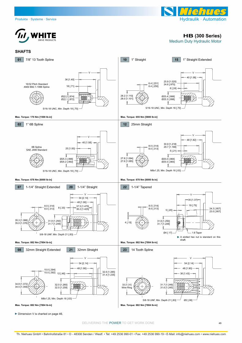
Medium Duty Hydraulic MotorHB (300 Series)
49DELIVERING THE POWER TO GET WORK DONE
SHAFTS
32.0 [1.260]32.0 [1.259]
V
54 [2.14]
M8x1.25, Min. Depth 16 [.63]
34.8 [1.372]34.5 [1.359]
32.6 [1.285]31.4 [1.235]
48 [1.90]
12 [.46]10.0 [.394]10.0 [.392]
V
35 [1.37]
19 [.75]
5 [.20]
4 [.15]
8.0 [.314]8.0 [.313] 24.3 [.957]
23.0 [.907]
1:8 TaperØ4 [.17]
31.8 [1.250]31.7 [1.249]
5 [.21]
30.9 [1.218]29.7 [1.168]8.0 [.314]
8.0 [.313]
27.8 [1.094]27.6 [1.085]
Ø25.0 [.984]Ø25.0 [.983]
V
M8x1.25, Min. Depth 16 [.63]
48 [1.82]
6 [.24]
25.9 [1.020]24.6 [.970]6.4 [.251]
6.4 [.250]
31.8 [1.250]31.7 [1.249]
25 [1.00]
18 [.71]
5/16-18 UNC, Min. Depth 18 [.70]
5/16-18 UNC, Min. Depth 18 [.70]
28.2 [1.110]28.0 [1.101]
Ø25.4 [.999]Ø25.3 [.998]
Ø22.2 [.874]Ø22.1 [.872]
Ø25.3 [.996]Ø25.2 [.992]
40 [1.58]
36 [1.40]
V
V54 [2.14]
VV
5/8-18 UNF, Min. Depth 21 [.83]
5/16-18 UNC, Min. Depth 18 [.70]
40 [1.58]
6B SplineSAE J499 Standard
16/32 Pitch StandardANSI B92.1-1996 Spline
35.3 [1.388]35.0 [1.376]
37.5 [1.475]36.2 [1.425]
48 [1.90]
8 [.33]8.0 [.314]8.0 [.313]
31.7 [1.249]31.6 [1.245]
V
54 [2.14]
5/8-18 UNF, Min. Depth 21 [.83] Ø2 [.06]
33 [1.31]Wire Ring
48 [1.90]
36 [1.43]
01 7/8” 13 Tooth Spline
Max. Torque: 170 Nm [1500 lb-in]
Max. Torque: 882 Nm [7804 lb-in]
02 1” 6B Spline
Max. Torque: 678 Nm [6000 lb-in]
07 1-1/4” Straight Extended 22 1-1/4” Tapered
23 14 Tooth Spline
Max. Torque: 882 Nm [7804 lb-in]
Max. Torque: 655 Nm [5800 lb-in]
20 1-1/4” Straight
12 25mm Straight
Max. Torque: 678 Nm [6000 lb-in]
08 32mm Straight Extended 21 32mm Straight
10 1” Straight 15 1” Straight Extended
Max. Torque: 882 Nm [7804 lb-in]
Max. Torque: 882 Nm [7804 lb-in]
A slotted hex nut is standard on this shaft.
Dimension V is charted on page 46.
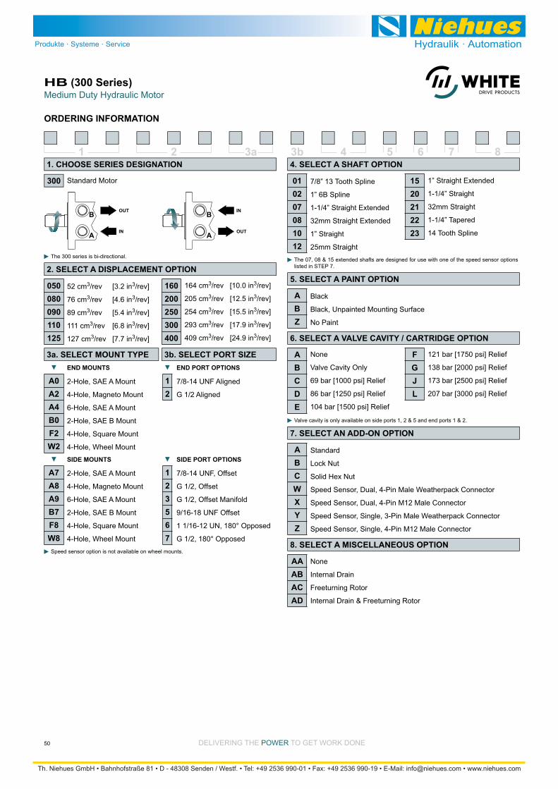
Medium Duty Hydraulic MotorHB (300 Series)
50 DELIVERING THE POWER TO GET WORK DONE
ORDERING INFORMATION
1 2 3b3a 4 5 6 7 8
52 cm3/rev [3.2 in3/rev]
76 cm3/rev [4.6 in3/rev]
89 cm3/rev [5.4 in3/rev]
111 cm3/rev [6.8 in3/rev]
127 cm3/rev [7.7 in3/rev]
Standard Motor
The 300 series is bi-directional.
164 cm3/rev [10.0 in3/rev]
205 cm3/rev [12.5 in3/rev]
254 cm3/rev [15.5 in3/rev]
293 cm3/rev [17.9 in3/rev]
409 cm3/rev [24.9 in3/rev]
2-Hole, SAE A Mount
4-Hole, Magneto Mount
6-Hole, SAE A Mount
2-Hole, SAE B Mount
4-Hole, Square Mount
4-Hole, Wheel Mount
7/8” 13 Tooth Spline
1” 6B Spline
1-1/4” Straight Extended
32mm Straight Extended
1” Straight
25mm Straight
1” Straight Extended
1-1/4” Straight
32mm Straight
1-1/4” Tapered
14 Tooth Spline
Black
Black, Unpainted Mounting Surface
No Paint
Standard
Lock Nut
Solid Hex Nut
Speed Sensor, Dual, 4-Pin Male Weatherpack Connector
Speed Sensor, Dual, 4-Pin M12 Male Connector
Speed Sensor, Single, 3-Pin Male Weatherpack Connector
Speed Sensor, Single, 4-Pin M12 Male Connector
None
Internal Drain
Freeturning Rotor
Internal Drain & Freeturning Rotor
The 07, 08 & 15 extended shafts are designed for use with one of the speed sensor options listed in STEP 7.
Speed sensor option is not available on wheel mounts.
None
Valve Cavity Only
69 bar [1000 psi] Relief
86 bar [1250 psi] Relief
104 bar [1500 psi] Relief
121 bar [1750 psi] Relief
138 bar [2000 psi] Relief
173 bar [2500 psi] Relief
207 bar [3000 psi] Relief
Valve cavity is only available on side ports 1, 2 & 5 and end ports 1 & 2.
7/8-14 UNF Aligned
G 1/2 Aligned
2-Hole, SAE A Mount
4-Hole, Magneto Mount
6-Hole, SAE A Mount
2-Hole, SAE B Mount
4-Hole, Square Mount
4-Hole, Wheel Mount
7/8-14 UNF, Offset
G 1/2, Offset
G 1/2, Offset Manifold
9/16-18 UNF Offset
1 1/16-12 UN, 180° Opposed
G 1/2, 180° Opposed
050080090110125
160200250300400
12
SIDE MOUNTS
300
1. CHOOSE SERIES DESIGNATION
2. SELECT A DISPLACEMENT OPTION
END MOUNTS
3a. SELECT MOUNT TYPE 3b. SELECT PORT SIZE
A0A2A4B0F2W2
4. SELECT A SHAFT OPTION
010207081012
1520212223
5. SELECT A PAINT OPTION
ABZ
6. SELECT A VALVE CAVITY / CARTRIDGE OPTION
7. SELECT AN ADD-ON OPTION
ABCWXYZ
8. SELECT A MISCELLANEOUS OPTION
AAABACAD
ABCDE
FGJL
END PORT OPTIONS
A7A8A9B7F8W8
123567
SIDE PORT OPTIONS

DELIVERING THE POWER TO GET WORK DONE
For Medium Duty ApplicationsCE (All Series)
51
Needle Roller Bearing is in optimum location to allow load to be placed as close to center line of bearing as possible.
Three Bearing Options allow load carrying capability of motor to be matched to application.
distribution of oil and reduces overall motor length.
Pressure-Compensated Balance Plate improves volu-
The combination of compact size, light weight and low speed
available. To reduce overall motor length and weight, all unnecessary material was removed from the housing and the valve was placed in the face of the rotor. The pressure-compensated balance plate allows the motor to maintain
for applications with strict weight and size requirements.
SPECIFICATIONS
OVERVIEW
FEATURES / BENEFITS
400/401 - Hydraulic Motor Standard
SERIES DESCRIPTIONS
Performance data is typical. Performance of production units varies slightly from one motor to another. Running at intermittent ratings should not exceed 10% of every minute of operation.
Medium-duty wheel drives, grapple heads, feed rollers, broom drives and more
TYPICAL APPLICATIONS
Max. Speed Max. Flow Max. Torque Max. Pressure rpm lpm [gpm] Nm [lb-in] bar [psi]
120 121 [7.4] 360 490 45 [12] 61 [16] 322 [2850] 356 [3150] 207 [3000] 224 [3250] 241 [3500] 160 162 [9.9] 370 470 61 [16] 76 [20] 424 [3750] 501 [4430] 207 [3000] 224 [3250] 241 [3500] 200 204 [12.4] 300 370 61 [16] 76 [20] 525 [4650] 593 [5250] 207 [3000] 224 [3250] 241 [3500] 230 232 [14.2] 260 320 61 [16] 76 [20] 559 [4950] 646 [5720] 207 [3000] 224 [3250] 241 [3500] 260 261 [15.9] 260 350 68 [18] 91 [24] 706 [6250] 760 [6730] 207 [3000] 224 [3250] 241 [3500] 300 300 [18.3] 250 320 76 [20] 95 [25] 802 [7100] 862 [7630] 207 [3000] 224 [3250] 241 [3500] 350 348 [21.2] 220 270 76 [20] 95 [25] 904 [8000] 1017 [9000] 207 [3000] 224 [3250] 241 [3500] 375 375 [22.8] 200 250 76 [20] 95 [25] 972 [8600] 1040 [9200] 207 [3000] 224 [3250] 241 [3500] 470 465 [28.3] 160 200 76 [20] 95 [25] 1040 [9200] 1153 [10200] 172 [2500] 189 [2750] 207 [3000] 540 536 [32.7] 140 170 76 [20] 95 [25] 1003 [8875] 1209 [10700] 138 [2000] 172 [2500] 207 [3000] 750 748 [45.6] 100 130 76 [20] 95 [25] 1082 [9575] 1237 [10950] 103 [1500] 121 [1750] 138 [2000]
CODE Displacement cm3 [in3/rev] cont. inter. cont. inter. cont. inter. cont. inter. peak
420/421 - Hydraulic Motor
430/431 - Hydraulic Motor
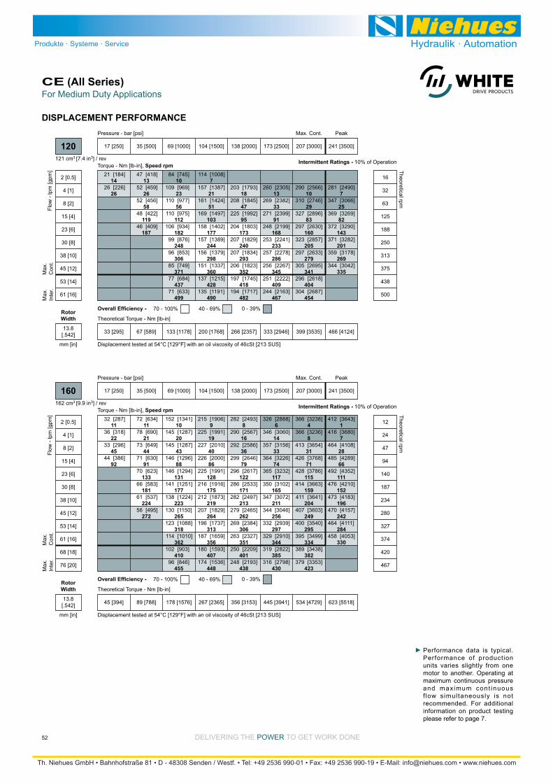
DELIVERING THE POWER TO GET WORK DONE
For Medium Duty ApplicationsCE (All Series)
52
DISPLACEMENT PERFORMANCE
14
26
13
26
58
119
187
10
23
56
112
182
248
306
371
437
499
7
21
51
103
177
244
298
360
428
490
18
47
95
173
240
293
352
418
482
13
33
91
168
233
286
345
409
467
10
29
83
160
205
279
341
404
454
7
25
82
143
201
269
335
[184]
[226]
21
26
[418]
[459]
[456]
[422]
[409]
47
52
52
48
46
[745]
[969]
[977]
[975]
[934]
[876]
[853]
[749]
[684]
[633]
84
109
110
110
106
99
96
85
77
71
[1008]
[1387]
[1424]
[1497]
[1402]
[1389]
[1379]
[1337]
[1215]
[1191]
114
157
161
169
158
157
156
151
137
135
[1793]
[1845]
[1992]
[1803]
[1829]
[1834]
[1823]
[1745]
[1717]
203
208
225
204
207
207
206
197
194
[2305]
[2382]
[2399]
[2199]
[2241]
[2278]
[2267]
[2222]
[2163]
260
269
271
248
253
257
256
251
244
[2566]
[2746]
[2896]
[2630]
[2857]
[2633]
[2695]
[2618]
[2687]
290
310
327
297
323
297
305
296
304
[2490]
[3066]
[3269]
[3290]
[3282]
[3178]
[3042]
281
347
369
372
371
359
344
Torque - Nm [lb-in], Speed rpm
Flow
- lp
m [g
pm]
17 [250] 35 [500] 69 [1000] 104 [1500] 138 [2000] 173 [2500] 207 [3000] 241 [3500]
Peak
33 [295] 67 [589] 133 [1178] 200 [1768] 266 [2357] 333 [2946] 399 [3535] 466 [4124]
Theoretical Torque - Nm [lb-in]
Max
.In
ter.
Max
.C
ont.
120
2 [0.5]
4 [1]
8 [2]
15 [4]
23 [6]
30 [8]
38 [10]
45 [12]
53 [14]
61 [16]
16
32
63
125
188
250
313
375
438
500
Theoretical rpm
Overall Efficiency - 70 - 100% 40 - 69% 0 - 39%
Intermittent Ratings - 10% of Operation
Displacement tested at 54°C [129°F] with an oil viscosity of 46cSt [213 SUS]
Max. Cont.Pressure - bar [psi]
121 cm3 [7.4 in3] / rev
mm [in]
RotorWidth
13.8[.542]
11
22
45
92
11
21
44
91
133
181
224
272
10
20
43
88
131
177
223
265
318
362
410
455
9
19
40
86
128
175
219
264
313
356
407
448
8
16
36
79
122
171
213
262
306
351
401
438
6
14
33
74
117
165
211
256
297
344
385
430
4
8
31
71
115
159
204
249
295
334
382
423
1
7
28
66
111
152
196
242
284
330
[287]
[318]
[296]
[386]
32
36
33
44
[634]
[690]
[649]
[630]
[623]
[583]
[537]
[495]
72
78
73
71
70
66
61
56
[1341]
[1287]
[1287]
[1296]
[1294]
[1251]
[1224]
[1150]
[1088]
[1010]
[903]
[846]
152
145
145
146
146
141
138
130
123
114
102
96
[1906]
[1991]
[2010]
[2000]
[1991]
[1916]
[1873]
[1829]
[1737]
[1659]
[1593]
[1536]
215
225
227
226
225
216
212
207
196
187
180
174
[2493]
[2567]
[2586]
[2646]
[2617]
[2533]
[2497]
[2465]
[2384]
[2327]
[2209]
[2193]
282
290
292
299
296
286
282
279
269
263
250
248
[2888]
[3060]
[3156]
[3226]
[3232]
[3102]
[3072]
[3046]
[2939]
[2910]
[2822]
[2798]
326
346
357
364
365
350
347
344
332
329
319
316
[3238]
[3236]
[3654]
[3768]
[3786]
[3663]
[3641]
[3603]
[3540]
[3499]
[3438]
[3353]
366
366
413
426
428
414
411
407
400
395
389
379
[3643]
[3680]
[4108]
[4289]
[4352]
[4210]
[4183]
[4157]
[4111]
[4053]
412
416
464
485
492
476
473
470
464
458
Torque - Nm [lb-in], Speed rpm
Flow
- lp
m [g
pm]
17 [250] 35 [500] 69 [1000] 104 [1500] 138 [2000] 173 [2500] 207 [3000] 241 [3500]
45 [394] 89 [788] 178 [1576] 267 [2365] 356 [3153] 445 [3941] 534 [4729] 623 [5518]
Theoretical Torque - Nm [lb-in]
Max
.In
ter.
Max
.C
ont.
160
2 [0.5]
4 [1]
8 [2]
15 [4]
23 [6]
30 [8]
38 [10]
45 [12]
53 [14]
61 [16]
68 [18]
76 [20]
12
24
47
94
140
187
234
280
327
374
420
467
Theoretical rpm
Overall Efficiency - 70 - 100% 40 - 69% 0 - 39%
Intermittent Ratings - 10% of Operation
Displacement tested at 54°C [129°F] with an oil viscosity of 46cSt [213 SUS]
PeakMax. Cont.Pressure - bar [psi]
162 cm3 [9.9 in3] / rev
mm [in]
RotorWidth
13.8[.542]
Performance data is typical. Performance of production units varies slightly from one motor to another. Operating at maximum continuous pressure and maximum cont inuous f low simultaneously is not recommended. For additional information on product testing please refer to page 7.
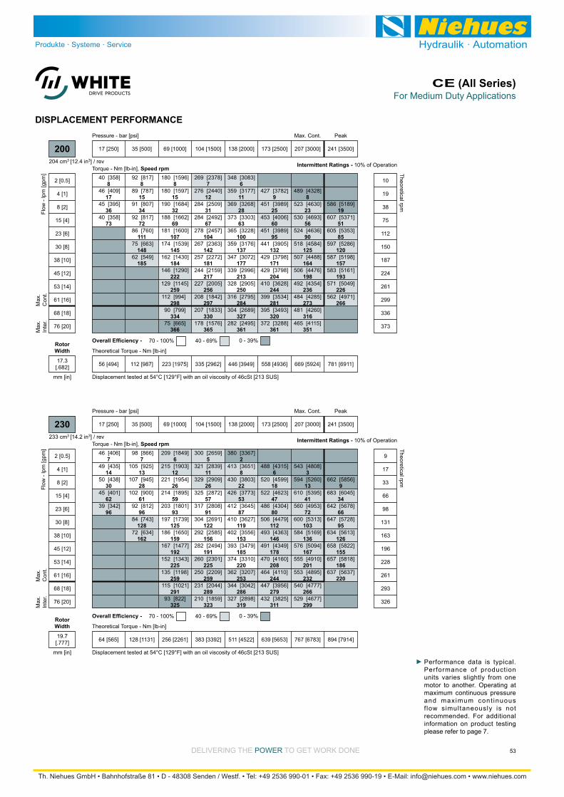
DELIVERING THE POWER TO GET WORK DONE
For Medium Duty ApplicationsCE (All Series)
53
DISPLACEMENT PERFORMANCE
8
17
36
73
8
15
34
72
111
148
185
8
15
32
69
107
145
184
222
259
298
334
366
7
12
31
67
104
142
181
217
256
297
330
365
6
11
28
63
100
137
177
213
250
284
327
361
9
25
60
95
132
171
204
244
281
320
361
8
23
56
90
125
164
198
236
273
316
351
19
51
85
120
157
193
226
266
[358]
[409]
[395]
[358]
40
46
45
40
[817]
[787]
[807]
[817]
[760]
[663]
[549]
92
89
91
92
86
75
62
[1596]
[1597]
[1684]
[1662]
[1600]
[1539]
[1430]
[1290]
[1145]
[994]
[799]
[665]
180
180
190
188
181
174
162
146
129
112
90
75
[2378]
[2440]
[2509]
[2492]
[2457]
[2363]
[2272]
[2159]
[2005]
[1842]
[1833]
[1576]
269
276
284
284
278
267
257
244
227
208
207
178
[3083]
[3177]
[3268]
[3303]
[3228]
[3176]
[3072]
[2996]
[2905]
[2795]
[2689]
[2495]
348
359
369
373
365
359
347
339
328
316
304
282
[3782]
[3989]
[4006]
[3989]
[3905]
[3798]
[3798]
[3628]
[3534]
[3493]
[3288]
427
451
453
451
441
429
429
410
399
395
372
[4328]
[4630]
[4693]
[4636]
[4584]
[4488]
[4476]
[4354]
[4285]
[4260]
[4115]
489
523
530
524
518
507
506
492
484
481
465
[5189]
[5371]
[5353]
[5286]
[5198]
[5161]
[5049]
[4971]
586
607
605
597
587
583
571
562
Torque - Nm [lb-in], Speed rpm
Flow
- lp
m [g
pm]
17 [250] 35 [500] 69 [1000] 104 [1500] 138 [2000] 173 [2500] 207 [3000] 241 [3500]
56 [494] 112 [987] 223 [1975] 335 [2962] 446 [3949] 558 [4936] 669 [5924] 781 [6911]
Theoretical Torque - Nm [lb-in]
Max
.In
ter.
Max
.C
ont.
200
2 [0.5]
4 [1]
8 [2]
15 [4]
23 [6]
30 [8]
38 [10]
45 [12]
53 [14]
61 [16]
68 [18]
76 [20]
10
19
38
75
112
150
187
224
261
299
336
373
Theoretical rpm
Overall Efficiency - 70 - 100% 40 - 69% 0 - 39%
Intermittent Ratings - 10% of Operation
Displacement tested at 54°C [129°F] with an oil viscosity of 46cSt [213 SUS]
PeakMax. Cont.Pressure - bar [psi]
204 cm3 [12.4 in3] / rev
mm [in]
RotorWidth
17.3[.682]
7
14
30
62
96
7
13
28
61
96
128
162
6
12
26
59
93
125
159
192
225
259
291
325
5
11
26
57
91
122
156
191
225
259
289
323
2
8
22
53
87
119
153
185
220
253
286
319
6
18
47
80
112
146
178
208
244
279
311
3
13
41
72
103
136
167
201
232
266
299
9
34
66
95
126
155
186
220
[406]
[435]
[438]
[401]
[342]
46
49
50
45
39
[866]
[925]
[945]
[900]
[812]
[743]
[634]
98
105
107
102
92
84
72
[1849]
[1903]
[1954]
[1895]
[1801]
[1739]
[1650]
[1477]
[1343]
[1198]
[1021]
[822]
209
215
221
214
203
197
186
167
152
135
115
93
[2659]
[2839]
[2909]
[2872]
[2808]
[2691]
[2585]
[2494]
[2301]
[2209]
[2044]
[1859]
300
321
329
325
317
304
292
282
260
250
231
210
[3367]
[3651]
[3803]
[3773]
[3645]
[3627]
[3556]
[3479]
[3310]
[3207]
[3042]
[2898]
380
413
430
426
412
410
402
393
374
362
344
327
[4315]
[4599]
[4623]
[4304]
[4479]
[4363]
[4349]
[4160]
[4110]
[3956]
[3825]
488
520
522
486
506
493
491
470
464
447
432
[4808]
[5260]
[5395]
[4953]
[5313]
[5169]
[5094]
[4910]
[4895]
[4777]
[4677]
543
594
610
560
600
584
576
555
553
540
529
[5856]
[6045]
[5678]
[5728]
[5613]
[5822]
[5818]
[5637]
662
683
642
647
634
658
657
637
Torque - Nm [lb-in], Speed rpm
Flow
- lp
m [g
pm]
17 [250] 35 [500] 69 [1000] 104 [1500] 138 [2000] 173 [2500] 207 [3000] 241 [3500]
64 [565] 128 [1131] 256 [2261] 383 [3392] 511 [4522] 639 [5653] 767 [6783] 894 [7914]
Theoretical Torque - Nm [lb-in]
Max
.In
ter.
Max
.C
ont.
230
2 [0.5]
4 [1]
8 [2]
15 [4]
23 [6]
30 [8]
38 [10]
45 [12]
53 [14]
61 [16]
68 [18]
76 [20]
9
17
33
66
98
131
163
196
228
261
293
326
Theoretical rpm
Overall Efficiency - 70 - 100% 40 - 69% 0 - 39%
Intermittent Ratings - 10% of Operation
Displacement tested at 54°C [129°F] with an oil viscosity of 46cSt [213 SUS]
PeakMax. Cont.Pressure - bar [psi]
233 cm3 [14.2 in3] / rev
mm [in]
RotorWidth
19.7[.777]
Performance data is typical. Performance of production units varies slightly from one motor to another. Operating at maximum continuous pressure and maximum cont inuous f low simultaneously is not recommended. For additional information on product testing please refer to page 7.

DELIVERING THE POWER TO GET WORK DONE
For Medium Duty ApplicationsCE (All Series)
54
DISPLACEMENT PERFORMANCE
6
12
26
54
84
5
10
23
51
81
113
142
173
203
232
4
9
20
48
74
107
137
169
201
131
258
287
319
348
3
8
20
46
74
105
134
166
195
226
255
286
319
346
1
6
17
42
69
100
128
161
191
220
248
281
312
335
2
13
36
60
89
119
152
183
210
242
271
299
333
7
30
53
81
109
143
170
199
229
257
287
332
21
45
71
98
129
157
189
215
[514]
[547]
[543]
[536]
[500]
58
62
61
61
57
[1120]
[1097]
[1150]
[1109]
[1067]
[981]
[909]
[771]
[664]
[538]
127
124
130
125
121
111
103
87
75
61
[2140]
[2191]
[2200]
[2284]
[2169]
[2143]
[2034]
[1915]
[1786]
[1687]
[1486]
[1345]
[1143]
[924]
242
248
249
258
245
242
230
216
202
191
168
152
129
104
[3068]
[3133]
[3295]
[3339]
[3326]
[3268]
[3161]
[3057]
[2928]
[2769]
[2614]
[1455]
[2208]
[2063]
347
354
372
377
376
369
357
345
331
313
295
277
249
233
[3759]
[3950]
[4234]
[4436]
[4406]
[4327]
[4273]
[4002]
[3841]
[3847]
[3664]
[3570]
[3372]
[3166]
425
446
478
501
498
489
483
452
434
435
414
403
381
358
[4377]
[4972]
[5306]
[5391]
[5374]
[5267]
[5111]
[4897]
[4892]
[4652]
[4598]
[4365]
[4168]
495
562
600
609
607
595
578
553
553
526
520
493
471
[5599]
[6192]
[6309]
[6290]
[6198]
[5708]
[5811]
[5803]
[5642]
[5585]
[5489]
[4875]
633
700
713
711
700
645
657
656
638
631
620
551
[6915]
[7214]
[7167]
[6740]
[6557]
[6718]
[6601]
[6567]
781
815
810
762
741
759
746
742
Torque - Nm [lb-in], Speed rpm
Flow
- lp
m [g
pm]
17 [250] 35 [500] 69 [1000] 104 [1500] 138 [2000] 173 [2500] 207 [3000] 241 [3500]
72 [633] 143 [1266] 286 [2532] 429 [3798] 572 [5064] 715 [6330] 858 [7596] 1001 [8861]
Theoretical Torque - Nm [lb-in]
Max
.In
ter.
Max
.C
ont.
260
2 [0.5]
4 [1]
8 [2]
15 [4]
23 [6]
30 [8]
38 [10]
45 [12]
53 [14]
61 [16]
68 [18]
76 [20]
83 [22]
91 [24]
8
15
30
59
88
117
146
175
204
233
262
291
320
349
Theoretical rpm
Overall Efficiency - 70 - 100% 40 - 69% 0 - 39%
Intermittent Ratings - 10% of Operation
Displacement tested at 54°C [129°F] with an oil viscosity of 46cSt [213 SUS]
PeakMax. Cont.Pressure - bar [psi]
261 cm3 [15.9 in3] / rev
mm [in]
RotorWidth
22.1[.872]
5
12
23
47
73
4
10
21
44
70
97
126
150
176
3
10
19
40
64
93
121
149
174
200
227
252
277
302
314
3
8
19
38
62
92
118
146
171
196
225
251
276
301
313
2
6
16
37
61
86
112
140
166
194
219
248
274
299
310
1
4
14
34
55
77
104
130
155
181
212
240
263
293
309
10
29
48
72
95
121
143
172
196
225
252
282
298
5
23
43
64
86
109
136
157
186
207
[559]
[493]
[522]
[503]
[447]
63
56
59
57
50
[1202]
[1230]
[1185]
[1189]
[1109]
[986]
[853]
[689]
[525]
136
139
134
134
125
111
96
78
59
[2518]
[2410]
[2676]
[2620]
[2534]
[2468]
[2306]
[2013]
[1889]
[1603]
[1405]
[1115]
[919]
[590]
[496]
285
272
302
296
286
279
261
228
213
181
159
126
104
67
56
[3656]
[3418]
[3781]
[3602]
[3886]
[3752]
[3687]
[3252]
[3410]
[3085]
[2823]
[2560]
[2309]
[1925]
[1740]
413
386
427
407
439
424
417
367
385
349
319
289
261
218
197
[4537]
[4272]
[4611]
[4398]
[4946]
[5020]
[4712]
[4434]
[4383]
[4195]
[4241]
[3703]
[3454]
[3441]
[3225]
513
483
521
497
559
567
532
501
495
474
479
418
390
389
364
[5129]
[4834]
[5196]
[5324]
[5992]
[6059]
[5832]
[5694]
[5509]
[5484]
[5112]
[4962]
[4907]
[4686]
[4281]
580
546
587
602
677
685
659
643
623
620
578
561
555
530
484
[5952]
[6161]
[6978]
[7142]
[7121]
[6781]
[6618]
[6471]
[6356]
[6221]
[6011]
[5766]
[5594]
673
696
789
807
805
766
748
731
718
703
679
652
632
[6572]
[6852]
[7762]
[8139]
[7994]
[7875]
[7186]
[7519]
[7348]
[7180]
743
774
877
920
903
890
812
850
830
811
Torque - Nm [lb-in], Speed rpm
Flow
- lp
m [g
pm]
17 [250] 35 [500] 69 [1000] 104 [1500] 138 [2000] 173 [2500] 207 [3000] 241 [3500]
82 [729] 165 [1457] 329 [2914] 494 [4371] 659 [5828] 823 [7285] 988 [8742] 1152 [10199]
Theoretical Torque - Nm [lb-in]
Max
.In
ter.
Max
.C
ont.
300
2 [0.5]
4 [1]
8 [2]
15 [4]
23 [6]
30 [8]
38 [10]
45 [12]
53 [14]
61 [16]
68 [18]
76 [20]
83 [22]
91 [24]
95 [25]
7
13
26
51
76
101
127
152
177
202
228
253
278
303
316
Theoretical rpm
Overall Efficiency - 70 - 100% 40 - 69% 0 - 39%
Intermittent Ratings - 10% of Operation
Displacement tested at 54°C [129°F] with an oil viscosity of 46cSt [213 SUS]
PeakMax. Cont.Pressure - bar [psi]
300 cm3 [18.3 in3] / rev
mm [in]
RotorWidth
25.4[1.000]
Performance data is typical. Performance of production units varies slightly from one motor to another. Operating at maximum continuous pressure and maximum cont inuous f low simultaneously is not recommended. For additional information on product testing please refer to page 7.
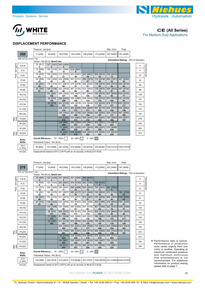
DELIVERING THE POWER TO GET WORK DONE
For Medium Duty ApplicationsCE (All Series)
55
DISPLACEMENT PERFORMANCE
5
10
21
43
65
87
5
10
21
42
65
86
108
130
152
4
10
21
42
64
85
107
129
151
174
196
216
239
261
272
9
20
40
31
84
106
128
150
173
194
213
237
258
270
18
37
57
80
100
124
148
171
192
212
234
257
264
16
36
53
75
94
115
137
163
187
209
232
256
261
13
32
52
67
85
104
127
152
177
194
223
248
259
25
43
61
77
94
117
139
165
183
[617]
[649]
[670]
[609]
[544]
[395]
70
73
76
69
62
45
[1297]
[1318]
[1403]
[1409]
[1319]
[1134]
[962]
[833]
[575]
147
149
159
159
149
128
109
94
65
[2383]
[2580]
[2767]
[2868]
[2837]
[2693]
[2550]
[2376]
[2162]
[1947]
[1644]
[1301]
[960]
[684]
[493]
269
291
313
324
321
304
288
268
244
220
186
147
109
77
56
[3647]
[4007]
[4101]
[4228]
[4134]
[4027]
[3889]
[3619]
[3406]
[3195]
[2863]
[2560]
[2225]
[2004]
412
453
463
478
467
455
439
409
385
361
324
289
251
226
[4927]
[5273]
[5363]
[5502]
[5500]
[5205]
[5059]
[4855]
[4599]
[4275]
[3921]
[3814]
[3621]
557
596
606
622
621
588
572
549
520
483
443
431
409
[5915]
[6316]
[6514]
[6870]
[6670]
[6712]
[6433]
[6172]
[6062]
[5634]
[5357]
[5207]
[5048]
668
714
736
776
754
758
727
697
685
637
605
588
570
[6919]
[7261]
[7475]
[8022]
[8028]
[7970]
[7777]
[7570]
[7297]
[6993]
[6814]
[6488]
[6435]
782
820
845
906
907
901
879
855
825
790
770
733
727
[8204]
[8410]
[8734]
[9105]
[9120]
[9070]
[8853]
[8555]
[8357]
927
950
987
1029
1031
1025
1000
967
944
Torque - Nm [lb-in], Speed rpm
Flow
- lp
m [g
pm]
17 [250] 35 [500] 69 [1000] 104 [1500] 138 [2000] 173 [2500] 207 [3000] 241 [3500]
95 [844] 191 [1688] 381 [3376] 572 [5064] 763 [6752] 954 [8439] 1144 [10127] 1335 [11815]
Theoretical Torque - Nm [lb-in]
Max
.In
ter.
Max
.C
ont.
350
2 [0.5]
4 [1]
8 [2]
15 [4]
23 [6]
30 [8]
38 [10]
45 [12]
53 [14]
61 [16]
68 [18]
76 [20]
83 [22]
91 [24]
95 [25]
6
11
22
44
66
88
109
131
153
175
197
218
240
262
273
Theoretical rpm
Overall Efficiency - 70 - 100% 40 - 69% 0 - 39%
Intermittent Ratings - 10% of Operation
Displacement tested at 54°C [129°F] with an oil viscosity of 46cSt [213 SUS]
PeakMax. Cont.Pressure - bar [psi]
348 cm3 [21.2 in3] / rev
mm [in]
RotorWidth
39.4[1.553]
4
9
19
39
60
81
4
8
18
38
59
80
101
121
141
162
4
8
17
36
58
77
99
119
140
161
182
201
222
243
253
3
7
16
36
56
76
97
117
139
160
181
200
220
242
251
2
6
15
33
51
71
92
112
135
155
177
198
219
241
250
4
13
29
44
63
83
107
126
147
168
193
210
232
242
9
26
40
55
74
93
114
135
164
178
203
220
235
25
43
61
77
94
117
139
165
183
[687]
[694]
[721]
[651]
[547]
[412]
78
78
81
74
62
47
[1438]
[1443]
[1495]
[1470]
[1372]
[1223]
[1048]
[870]
[625]
[487]
162
163
169
166
155
138
118
98
71
55
[2840]
[2951]
[3001]
[2837]
[3015]
[2836]
[2684]
[2547]
[2308]
[2134]
[1805]
[1942]
[1173]
[881]
[711]
321
333
339
321
341
320
303
288
261
241
204
219
132
100
80
[3958]
[4193]
[4288]
[4117]
[4557]
[4453]
[4382]
[4147]
[3849]
[3744]
[3461]
[3231]
[2795]
[2567]
[2313]
447
474
485
465
515
503
495
469
435
423
391
365
316
290
261
[5237]
[5366]
[5533]
[5404]
[5931]
[5880]
[5726]
[5620]
[5337]
[5248]
[4988]
[4714]
[4552]
[4202]
[4113]
592
606
625
611
670
664
647
635
603
593
564
533
514
475
465
[6457]
[6692]
[6624]
[6946]
[7385]
[7090]
[7115]
[6953]
[6706]
[6402]
[5860]
[5970]
[5667]
[5454]
730
756
748
785
834
801
804
786
758
723
662
675
640
616
[7532]
[7754]
[7825]
[8633]
[8161]
[8605]
[8298]
[8160]
[7899]
[7643]
[7141]
[7012]
[6891]
851
876
884
976
922
972
938
922
893
864
807
792
779
[8766]
[8896]
[9442]
[9364]
[9920]
[9771]
[9614]
[9320]
[9112]
991
1005
1067
1058
1121
1104
1086
1053
1030
Torque - Nm [lb-in], Speed rpm
Flow
- lp
m [g
pm]
17 [250] 35 [500] 69 [1000] 104 [1500] 138 [2000] 173 [2500] 207 [3000] 241 [3500]
103 [908] 205 [1815] 410 [3631] 615 [5446] 821 [7261] 1026 [9076] 1231 [10892] 1436 [12707]
Theoretical Torque - Nm [lb-in]
Max
.In
ter.
Max
.C
ont.
375
2 [0.5]
4 [1]
8 [2]
15 [4]
23 [6]
30 [8]
38 [10]
45 [12]
53 [14]
61 [16]
68 [18]
76 [20]
83 [22]
91 [24]
95 [25]
6
11
21
41
61
82
102
122
142
163
183
203
223
244
254
Theoretical rpm
Overall Efficiency - 70 - 100% 40 - 69% 0 - 39%
Intermittent Ratings - 10% of Operation
Displacement tested at 54°C [129°F] with an oil viscosity of 46cSt [213 SUS]
PeakMax. Cont.Pressure - bar [psi]
375 cm3 [22.8 in3] / rev
mm [in]
RotorWidth
31.8[1.252]
Performance data is typical. Performance of production units varies slightly from one motor to another. Operating at maximum continuous pressure and maximum cont inuous f low simultaneously is not recommended. For additional information on product testing please refer to page 7.
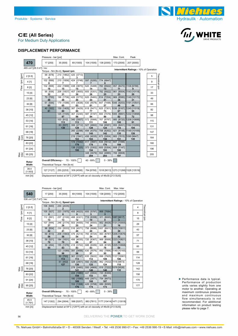
DELIVERING THE POWER TO GET WORK DONE
For Medium Duty ApplicationsCE (All Series)
56
DISPLACEMENT PERFORMANCE
4
8
16
32
48
65
81
3
7
15
31
48
65
80
97
113
130
3
7
15
30
46
63
80
96
113
129
146
163
179
195
7
14
28
44
61
77
94
111
128
145
163
178
194
204
6
13
25
41
57
73
90
106
124
142
158
176
193
203
11
23
36
48
67
82
100
116
135
151
168
186
197
9
20
31
44
55
72
91
105
126
140
[878]
[899]
[906]
[836]
[700]
[544]
[352]
99
102
102
95
79
61
40
[1862]
[1856]
[1968]
[1837]
[1736]
[1588]
[1405]
[1105]
[912]
[557]
210
210
222
208
196
179
159
125
103
63
[3713]
[3748]
[3875]
[3600]
[3772]
[3638]
[3429]
[3245]
[3007]
[2712]
[2298]
[1941]
[1542]
[1225]
420
424
438
407
426
411
387
367
340
306
260
219
174
138
[5285]
[5488]
[5351]
[5483]
[5578]
[5471]
[5197]
[5066]
[4662]
[4370]
[4035]
[3687]
[3302]
[3079]
597
620
605
620
630
618
587
572
527
494
456
417
373
348
[6847]
[6922]
[6922]
[7204]
[7498]
[7301]
[7076]
[6787]
[6581]
[6262]
[5954]
[5612]
[5354]
[4885]
774
782
782
814
847
825
800
767
744
708
673
634
605
552
[8470]
[8504]
[8580]
[9253]
[9167]
[8891]
[8720]
[8451]
[8148]
[7815]
[7496]
[7147]
[6808]
957
961
969
1046
1036
1005
985
955
921
883
847
808
769
[9788]
[10118]
[10172]
[10541]
[11019]
[10898]
[10688]
[10285]
[10169]
[9647]
1106
1143
1149
1191
1245
1232
1208
1162
1149
1090
Torque - Nm [lb-in], Speed rpm
Flow
- lp
m [g
pm]
17 [250] 35 [500] 69 [1000] 104 [1500] 138 [2000] 173 [2500] 207 [3000]
127 [1127] 255 [2253] 509 [4506] 764 [6760] 1018 [9013] 1273 [11266] 1528 [13519]
Theoretical Torque - Nm [lb-in]
Max
.In
ter.
Max
.C
ont.
470
2 [0.5]
4 [1]
8 [2]
15 [4]
23 [6]
30 [8]
38 [10]
45 [12]
53 [14]
61 [16]
68 [18]
76 [20]
83 [22]
91 [24]
95 [25]
5
9
17
33
49
66
82
98
115
131
147
164
180
196
205
Theoretical rpm
Overall Efficiency - 70 - 100% 40 - 69% 0 - 39%
Intermittent Ratings - 10% of Operation
Displacement tested at 54°C [129°F] with an oil viscosity of 46cSt [213 SUS]
PeakMax. Cont.Pressure - bar [psi]
465 cm3 [28.3 in3] / rev
mm [in]
RotorWidth
39.4[1.553]
3
6
13
27
42
56
70
84
2
6
13
26
41
56
70
83
98
113
127
6
12
25
40
54
69
83
98
113
126
141
154
169
176
5
10
24
40
54
67
83
97
112
125
140
153
168
174
3
8
21
36
49
64
78
95
109
124
140
151
167
173
3
16
30
42
56
69
88
106
118
132
[940]
[927]
[991]
[944]
[854]
[613]
[521]
[264]
106
105
112
107
96
69
59
30
[2035]
[1975]
[2100]
[2174]
[2033]
[1843]
[1631]
[1376]
[1089]
[793]
[452]
230
223
237
246
230
208
184
155
123
90
51
[4023]
[4321]
[4455]
[4571]
[4214]
[4035]
[3702]
[3456]
[3197]
[2901]
[2460]
[1980]
[1590]
[1358]
455
488
503
516
476
456
418
391
361
328
278
224
180
153
[5797]
[6358]
[6593]
[6686]
[6724]
[6367]
[6089]
[5576]
[5622]
[5238]
[4869]
[3954]
[3971]
[3768]
655
719
745
756
760
720
688
630
635
592
550
447
449
426
[7684]
[8065]
[8426]
[8911]
[8787]
[8568]
[8195]
[7896]
[7925]
[7632]
[7222]
[6369]
[6673]
[6095]
868
911
952
1007
993
968
926
892
896
862
816
720
754
689
[9617]
[10005]
[10911]
[10676]
[10821]
[10668]
[10165]
[10061]
[9873]
[9526]
1087
1131
1233
1206
1223
1205
1149
1137
1116
1076
Torque - Nm [lb-in], Speed rpm
Flow
- lp
m [g
pm]
17 [250] 35 [500] 69 [1000] 104 [1500] 138 [2000] 172 [2500]
147 [1302] 294 [2604] 588 [5207] 883 [7811] 1177 [10414] 1471 [13018]
Theoretical Torque - Nm [lb-in]
Max
.In
ter.
Max
.C
ont.
540
2 [0.5]
4 [1]
8 [2]
15 [4]
23 [6]
30 [8]
38 [10]
45 [12]
53 [14]
61 [16]
68 [18]
76 [20]
83 [22]
91 [24]
95 [25]
4
8
15
29
43
57
71
85
99
114
128
142
156
170
177
Theoretical rpm
Overall Efficiency - 70 - 100% 40 - 69% 0 - 39%
Intermittent Ratings - 10% of Operation
Displacement tested at 54°C [129°F] with an oil viscosity of 46cSt [213 SUS]
Max. InterMax. Cont.Pressure - bar [psi]
536 cm3 [32.7 in3] / rev
mm [in]
RotorWidth
45.5[1.791]
Performance data is typical. Performance of production units varies slightly from one motor to another. Operating at maximum continuous pressure and maximum cont inuous f low simultaneously is not recommended. For additional information on product testing please refer to page 7.
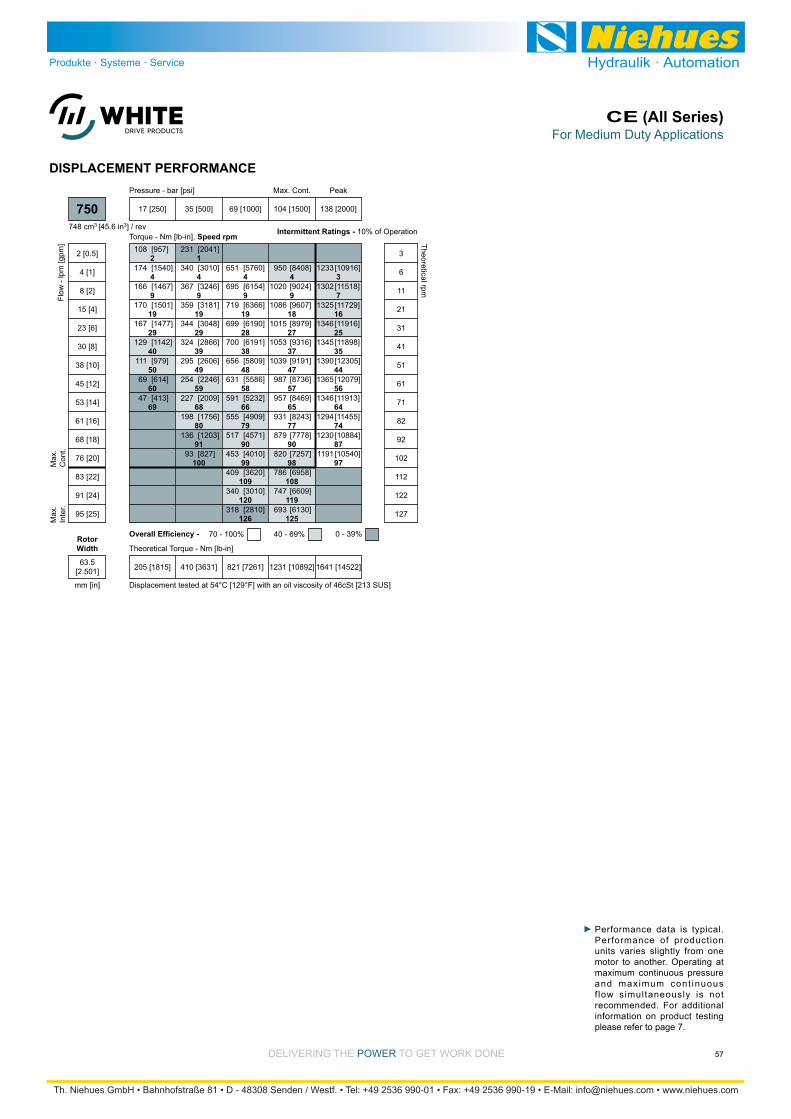
DELIVERING THE POWER TO GET WORK DONE
For Medium Duty ApplicationsCE (All Series)
57
DISPLACEMENT PERFORMANCE
2
4
9
19
29
40
50
60
69
1
4
9
19
29
39
49
59
68
80
91
100
4
9
19
28
38
48
58
66
79
90
99
109
120
126
4
9
18
27
37
47
57
65
77
90
98
108
119
125
3
7
16
25
35
44
56
64
74
87
97
[957]
[1540]
[1467]
[1501]
[1477]
[1142]
[979]
[614]
[413]
108
174
166
170
167
129
111
69
47
[2041]
[3010]
[3246]
[3181]
[3048]
[2866]
[2606]
[2246]
[2009]
[1756]
[1203]
[827]
231
340
367
359
344
324
295
254
227
198
136
93
[5760]
[6154]
[6366]
[6190]
[6191]
[5809]
[5586]
[5232]
[4909]
[4571]
[4010]
[3620]
[3010]
[2810]
651
695
719
699
700
656
631
591
555
517
453
409
340
318
[8408]
[9024]
[9607]
[8979]
[9316]
[9191]
[8736]
[8469]
[8243]
[7778]
[7257]
[6958]
[6609]
[6130]
950
1020
1086
1015
1053
1039
987
957
931
879
820
786
747
693
[10916]
[11518]
[11729]
[11916]
[11898]
[12305]
[12079]
[11913]
[11455]
[10884]
[10540]
1233
1302
1325
1346
1345
1390
1365
1346
1294
1230
1191
Torque - Nm [lb-in], Speed rpm
Flow
- lp
m [g
pm]
17 [250] 35 [500] 69 [1000] 104 [1500] 138 [2000]
Pressure - bar [psi]
205 [1815] 410 [3631] 821 [7261] 1231 [10892] 1641 [14522]
Theoretical Torque - Nm [lb-in]
Max
.In
ter.
Max
.C
ont.
750
2 [0.5]
4 [1]
8 [2]
15 [4]
23 [6]
30 [8]
38 [10]
45 [12]
53 [14]
61 [16]
68 [18]
76 [20]
83 [22]
91 [24]
95 [25]
3
6
11
21
31
41
51
61
71
82
92
102
112
122
127
Theoretical rpm
Overall Efficiency - 70 - 100% 40 - 69% 0 - 39%
Intermittent Ratings - 10% of Operation
Displacement tested at 54°C [129°F] with an oil viscosity of 46cSt [213 SUS]
PeakMax. Cont.
748 cm3 [45.6 in3] / rev
mm [in]
RotorWidth
63.5[2.501]
Performance data is typical. Performance of production units varies slightly from one motor to another. Operating at maximum continuous pressure and maximum cont inuous f low simultaneously is not recommended. For additional information on product testing please refer to page 7.

Medium Duty Hydraulic MotorCE (400/401 Series)
58 DELIVERING THE POWER TO GET WORK DONE
HOUSINGS
Dimension GG is charted on page 59.
13.3 [.524]13.1 [.514]
82.5 [3.249]82.4 [3.246]
23 [.90]
15 [.61]
127.0 [4.999]126.8 [4.994]
42.2 [1.660]42.0 [1.655]
138 [5.45] Max.
Ø 147.6 [5.812]45°
63 [2.47] Min.
132 [5.21] Max.
23 [.90]
3 [.10] Min.
37 [1.47]
A
B
57 [.25]
105 [4.13]
18 [.71]
30 [1.17]
GG
E
F
B A
W38 G 1/24-HOLE, WHEEL MOUNT, ALIGNED PORTS W31 7/8-14 UNF
E: 10 Series/2-Way Valve Cavity 7/8-14 UNF F: Valve Cartridge Installed
STANDARD
OPTIONAL VALVE CAVITY

Medium Duty Hydraulic MotorCE (400/401 Series)
59DELIVERING THE POWER TO GET WORK DONE
TECHNICAL INFORMATION
3000
8000
WHEEL MOUNTS
7000
6000
5000
4000
lb
2000
1000
1000
3500
3000
2500
2000
1500
daN
500
4 in5-2 32-1 10
100 mm125-50 7550-25 250
445 daN [1000 lb]
445 daN [1000 lb]
SHAFT
BEARING
The bearing curve represents allowable bearing loads based on ISO 281 bearing capacity for an L10 life of 2,000 hours at 100 rpm. Radial loads for speeds other than 100 rpm may be calculated using the multiplication factor table on page 8.
ALLOWABLE SHAFT LOAD / BEARING CURVE LENGTH & WEIGHT CHARTDimension GG is the overall motor length from the rear of the motor to
is referenced on detailed housing drawings listed on pages 58, 61 & 64.
All CE series motor weights can vary ± 0.5
such as housing, shaft, endcover, options etc.
Length Weight
#120160200230260300350375470540750
kg [lb]
10.9 [24.1]
10.9 [24.1]
11.3 [24.8]
11.4 [25.2]
11.6 [25.6]
11.9 [26.3]
13.1 [28.8]
12.4 [27.4]
13.1 [28.8]
13.6 [30.0]
15.0 [33.1]
mm [in]
99 [3.91]
99 [3.91]
103 [4.05]
105 [4.15]
108 [4.24]
111 [4.37]
125 [4.92]
117 [4.62]
125 [4.92]
131 [5.16]
149 [5.87]
GG
SHAFTS
*100 [3.94]
35 [1.37]
19 [.75]
5 [.20]
4 [.15]
8.0 [.314]8.0 [.313] 24.3 [.957]
23.0 [.907]
1:8 TaperØ4 [.17]
31.8 [1.250]31.7 [1.249]
31.8 [1.250]31.7 [1.249]
*102 [4.03]54 [2.14]
5/8-18 UNF,Min. Depth 21 [.83]
35.3 [1.388]35.0 [1.376]
37.5 [1.475]36.2 [1.425]
48 [1.90]
8 [.33]8.0 [.314]8.0 [.313]
31.7 [1.249]31.6 [1.245]
*102 [4.03]
54 [2.14]
5/8-18 UNF, Min. Depth 21 [.83] Ø2 [.06]
33 [1.31]Wire Ring
48 [1.90]
36 [1.43]
Wire Ring34 [1.33]
14 tooth 12/24 PitchStd. ANSI B92.1-1996 Spline
Max. Torque: 1200 Nm [10600 lb-in]
20 1-1/4” Straight 22 1-1/4” Tapered
23 14 Tooth Spline
Max. Torque: 1200 Nm [10600 lb-in]
Max. Torque: 1200 Nm [10600 lb-in]
A slotted hex nut is standard on this shaft.

Medium Duty Hydraulic MotorCE (400/401 Series)
60 DELIVERING THE POWER TO GET WORK DONE
ORDERING INFORMATION
1 2 3 4 5 6 7 8
121 cm3/rev [7.4 in3/rev]
162 cm3/rev [9.9 in3/rev]
204 cm3/rev [12.4 in3/rev]
232 cm3/rev [14.2 in3/rev]
261 cm3/rev [15.9 in3/rev]
300 cm3/rev [18.3 in3/rev]
Standard Rotation Reverse Rotation
The 400 & 401 series are bi-directional. For applications requiring the motor to rotate in only one direction, shaft seal life may be prolonged by pressurizing the A port of the motor.
348 cm3/rev [21.2 in3/rev]
375 cm3/rev [22.8 in3/rev]
465 cm3/rev [28.3 in3/rev]
536 cm3/rev [32.7 in3/rev]
748 cm3/rev [45.6 in3/rev]
4-Hole, Wheel Mount, Aligned Ports, 7/8-14 UNF
4-Hole, Wheel Mount, Aligned Ports, G 1/2
1-1/4” Straight
1-1/4” Tapered
14 Tooth Spline
Black
Black, Unpainted Mounting Surface
No Paint
Standard
Lock Nut
Solid Hex Nut
None
Freeturning Rotor
Hydraulic Declutch With Freeturning Rotor
None
Valve Cavity Only
69 bar [1000 psi] Relief
86 bar [1250 psi] Relief
104 bar [1500 psi] Relief
121 bar [1750 psi] Relief
138 bar [2000 psi] Relief
400
1. CHOOSE SERIES DESIGNATION
2. SELECT A DISPLACEMENT OPTION
120160200230260300
350375470540750
3. SELECT A MOUNT & PORT OPTION
W31W38
4. SELECT A SHAFT OPTION
2022
23
5. SELECT A PAINT OPTION
ABZ
6. SELECT A VALVE CAVITY / CARTRIDGE OPTION
7. SELECT AN ADD-ON OPTION
ABC
8. SELECT A MISCELLANEOUS OPTION
AAACAE
401
ABCD
EFG

Medium Duty Hydraulic MotorCE (420/421 Series)
61DELIVERING THE POWER TO GET WORK DONE
HOUSINGS
Dimension GG is charted on page 59.
88.8 [3.498]88.7 [3.494]
23 [.90]
18 [.71]
127.0 [4.999]126.8 [4.994]
44.3 [1.743]44.1 [1.738]
23 [.90]
3 [.10] Min.
38 [1.48]
A
B
GG
13.3 [.524]13.1 [.514]
138 [5.45] Max.
Ø 147.6 [5.812]
45°
63 [2.49] Min.
131 [5.15] Max.
82.5 [3.249]82.4 [3.246]
23 [.90]
18 [71]
127.0 [4.999]126.8 [4.994]
44.3 [1.743]44.1 [1.738]
23 [.90]
3 [.10] Min.
38 [1.48]
A
B
GG
13.3 [.524]13.1 [.514]
138 [5.45] Max.
Ø 147.6 [5.812]
45°
63 [2.49] Min.
131 [5.15] Max.
4-HOLE, 3.50” PILOT WHEEL MOUNT, ALIGNED PORTS W31 7/8-14 UNF W35 9/16-18 UNF
4-HOLE, 3.25” PILOT WHEEL MOUNT, ALIGNED PORTS P31 7/8-14 UNF P38 G 1/2
W38 G 1/2
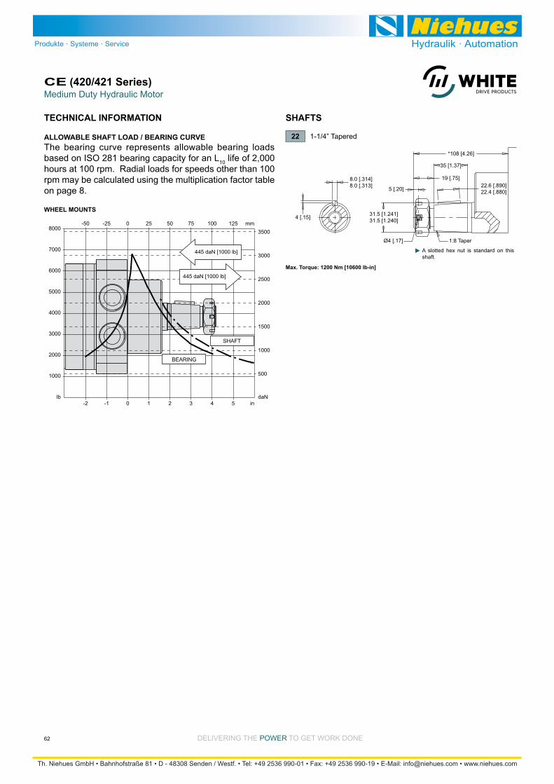
Medium Duty Hydraulic MotorCE (420/421 Series)
62 DELIVERING THE POWER TO GET WORK DONE
TECHNICAL INFORMATION
3000
8000
WHEEL MOUNTS
7000
6000
5000
4000
lb
2000
1000
1000
3500
3000
2500
2000
1500
daN
500
4 in5-2 32-1 10
100 mm125-50 7550-25 250
445 daN [1000 lb]
445 daN [1000 lb]
SHAFT
BEARING
The bearing curve represents allowable bearing loads based on ISO 281 bearing capacity for an L10 life of 2,000 hours at 100 rpm. Radial loads for speeds other than 100 rpm may be calculated using the multiplication factor table on page 8.
ALLOWABLE SHAFT LOAD / BEARING CURVE
SHAFTS
*108 [4.26]
35 [1.37]
19 [.75]
5 [.20]
4 [.15]
8.0 [.314]8.0 [.313] 22.6 [.890]
22.4 [.880]
1:8 TaperØ4 [.17]
31.5 [1.241]31.5 [1.240]
22 1-1/4” Tapered
Max. Torque: 1200 Nm [10600 lb-in]
A slotted hex nut is standard on this shaft.
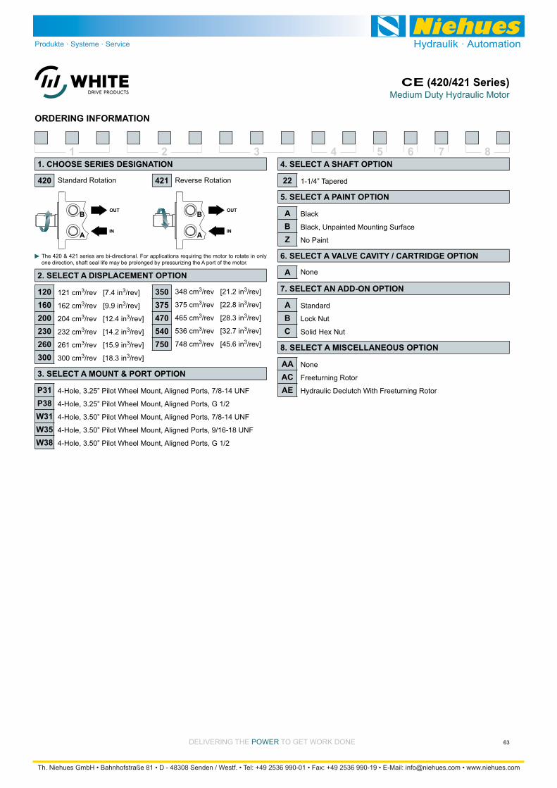
Medium Duty Hydraulic MotorCE (420/421 Series)
63DELIVERING THE POWER TO GET WORK DONE
ORDERING INFORMATION
1 2 3 4 5 6 7 8
121 cm3/rev [7.4 in3/rev]
162 cm3/rev [9.9 in3/rev]
204 cm3/rev [12.4 in3/rev]
232 cm3/rev [14.2 in3/rev]
261 cm3/rev [15.9 in3/rev]
300 cm3/rev [18.3 in3/rev]
Standard Rotation Reverse Rotation
The 420 & 421 series are bi-directional. For applications requiring the motor to rotate in only one direction, shaft seal life may be prolonged by pressurizing the A port of the motor.
348 cm3/rev [21.2 in3/rev]
375 cm3/rev [22.8 in3/rev]
465 cm3/rev [28.3 in3/rev]
536 cm3/rev [32.7 in3/rev]
748 cm3/rev [45.6 in3/rev]
4-Hole, 3.25” Pilot Wheel Mount, Aligned Ports, 7/8-14 UNF
4-Hole, 3.25” Pilot Wheel Mount, Aligned Ports, G 1/2
4-Hole, 3.50” Pilot Wheel Mount, Aligned Ports, 7/8-14 UNF
4-Hole, 3.50” Pilot Wheel Mount, Aligned Ports, 9/16-18 UNF
4-Hole, 3.50” Pilot Wheel Mount, Aligned Ports, G 1/2
1-1/4” Tapered
Black
Black, Unpainted Mounting Surface
No Paint
Standard
Lock Nut
Solid Hex Nut
None
Freeturning Rotor
Hydraulic Declutch With Freeturning Rotor
None
420
1. CHOOSE SERIES DESIGNATION
2. SELECT A DISPLACEMENT OPTION
120160200230260300
350375470540750
3. SELECT A MOUNT & PORT OPTION
P31P38W31W35W38
4. SELECT A SHAFT OPTION
22
5. SELECT A PAINT OPTION
ABZ
6. SELECT A VALVE CAVITY / CARTRIDGE OPTION
7. SELECT AN ADD-ON OPTION
ABC
8. SELECT A MISCELLANEOUS OPTION
AAACAE
421
A

Medium Duty Hydraulic MotorCE (430/431 Series)
64 DELIVERING THE POWER TO GET WORK DONE
HOUSINGS
Dimension GG is charted on page 59.
13.3 [.524]13.1 [.514]
82.5 [3.249]82.4 [3.246]
23 [.90]
15 [.61]
127.0 [4.999]126.8 [4.994]
42.2 [1.660]42.0 [1.655]
138 [5.45] Max.
Ø 147.6 [5.812]45°
63 [2.47] Min.
132 [5.21] Max.
23 [.90]
3 [.10] Min.
37 [1.47]
A
B
57 [.25]
105 [4.13]
18 [.71]
30 [1.17]
GG
E
F
B A
W38 G 1/24-HOLE, WHEEL MOUNT, ALIGNED PORTS W31 7/8-14 UNF
E: 10 Series/2-Way Valve Cavity 7/8-14 UNF F: Valve Cartridge Installed
STANDARD
OPTIONAL VALVE CAVITY
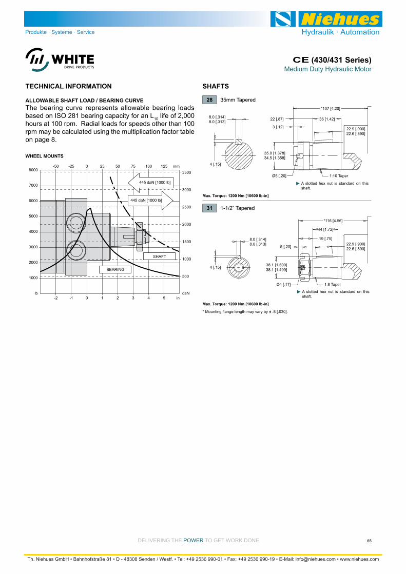
Medium Duty Hydraulic MotorCE (430/431 Series)
65DELIVERING THE POWER TO GET WORK DONE
TECHNICAL INFORMATION
The bearing curve represents allowable bearing loads based on ISO 281 bearing capacity for an L10 life of 2,000 hours at 100 rpm. Radial loads for speeds other than 100 rpm may be calculated using the multiplication factor table on page 8.
ALLOWABLE SHAFT LOAD / BEARING CURVE
SHAFTS
*107 [4.20]
4 [.15]
8.0 [.314]8.0 [.313]
22.9 [.900]22.6 [.890]
36 [1.42]22 [.87]
Ø5 [.20]
3 [.12]
35.0 [1.378]34.5 [1.358]
1:10 Taper
*116 [4.56]
44 [1.72]
19 [.75]
5 [.20]
4 [.15]
8.0 [.314]8.0 [.313] 22.9 [.900]
22.6 [.890]
1:8 TaperØ4 [.17]
38.1 [1.500]38.1 [1.499]
Max. Torque: 1200 Nm [10600 lb-in]
31 1-1/2” Tapered
28 35mm Tapered
Max. Torque: 1200 Nm [10600 lb-in]
A slotted hex nut is standard on this shaft.
A slotted hex nut is standard on this shaft.
* Mounting flange length may vary by ± .8 [.030].
3000
8000
WHEEL MOUNTS
7000
6000
5000
4000
lb
2000
1000
1000
3500
3000
2500
2000
1500
daN
500
4 in5-2 32-1 10
100 mm125-50 7550-25 250
445 daN [1000 lb]
445 daN [1000 lb]
SHAFT
BEARING

Medium Duty Hydraulic MotorCE (430/431 Series)
66 DELIVERING THE POWER TO GET WORK DONE
ORDERING INFORMATION
1 2 3 4 5 6 7 8
121 cm3/rev [7.4 in3/rev]
162 cm3/rev [9.9 in3/rev]
204 cm3/rev [12.4 in3/rev]
232 cm3/rev [14.2 in3/rev]
261 cm3/rev [15.9 in3/rev]
300 cm3/rev [18.3 in3/rev]
Standard Rotation Reverse Rotation
The 430 & 431 series are bi-directional. For applications requiring the motor to rotate in only one direction, shaft seal life may be prolonged by pressurizing the A port of the motor.
348 cm3/rev [21.2 in3/rev]
375 cm3/rev [22.8 in3/rev]
465 cm3/rev [28.3 in3/rev]
536 cm3/rev [32.7 in3/rev]
748 cm3/rev [45.6 in3/rev]
4-Hole, Wheel Mount, Aligned Ports, 7/8-14 UNF
4-Hole, Wheel Mount, Aligned Ports, G 1/2
35mm Tapered 1-1/2” Tapered
Black
Black, Unpainted Mounting Surface
No Paint
Standard
Lock Nut
Solid Hex Nut
None
Freeturning Rotor
Hydraulic Declutch With Freeturning Rotor
None
Valve Cavity Only
69 bar [1000 psi] Relief
86 bar [1250 psi] Relief
104 bar [1500 psi] Relief
121 bar [1750 psi] Relief
138 bar [2000 psi] Relief
430
1. CHOOSE SERIES DESIGNATION
2. SELECT A DISPLACEMENT OPTION
120160200230260300
350375470540750
3. SELECT A MOUNT & PORT OPTION
W31W38
4. SELECT A SHAFT OPTION
28 31
5. SELECT A PAINT OPTION
ABZ
6. SELECT A VALVE CAVITY / CARTRIDGE OPTION
7. SELECT AN ADD-ON OPTION
ABC
8. SELECT A MISCELLANEOUS OPTION
AAACAE
431
ABCD
EFG
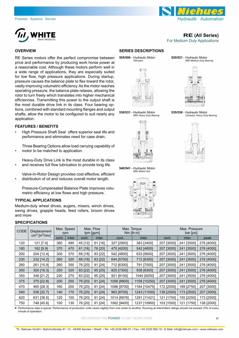
DELIVERING THE POWER TO GET WORK DONE
For Medium Duty ApplicationsRE (All Series)
67
High Pressure Shaft Seal offers superior seal life and performance and eliminates need for case drain.
Three Bearing Options allow load carrying capability of motor to be matched to application.
distribution of oil and reduces overall motor length.
Pressure-Compensated Balance Plate improves volu-
RE Series motors offer the perfect compromise between
a reasonable cost. Although these motors perform well in a wide range of applications, they are especially suited
operating pressure, the balance plate relaxes, allowing the rotor to turn freely which translates into higher mechanical
-
application.
SPECIFICATIONS
OVERVIEW
FEATURES / BENEFITS
505/506 - Hydraulic Motor Standard
SERIES DESCRIPTIONS
Medium-duty wheel drives, augers, mixers, winch drives, swing drives, grapple heads, feed rollers, broom drives and more
TYPICAL APPLICATIONS
535/536 - Hydraulic Motor
520/521 - Hydraulic Motor
530/531 - Hydraulic Motor
Performance data is typical. Performance of production units varies slightly from one motor to another. Running at intermittent ratings should not exceed 10% of every minute of operation.
120 121 [7.4] 360 490 45 [12] 61 [16] 327 [2900] 383 [3400] 207 [3000] 241 [3500] 276 [4000] 160 162 [9.9] 370 470 61 [16] 76 [20] 475 [4200] 542 [4800] 207 [3000] 241 [3500] 276 [4000] 200 204 [12.4] 300 370 68 [18] 83 [22] 542 [4800] 633 [5600] 207 [3000] 241 [3500] 276 [4000] 230 232 [14.2] 260 320 68 [18] 83 [22] 644 [5700] 712 [6300] 207 [3000] 241 [3500] 276 [4000] 260 261 [15.9] 260 350 76 [20] 91 [24] 712 [6300] 791 [7000] 207 [3000] 241 [3500] 276 [4000] 300 300 [18.3] 250 320 83 [22] 95 [25] 825 [7300] 938 [8300] 207 [3000] 241 [3500] 276 [4000] 350 348 [21.2] 220 270 83 [22] 95 [25] 921 [8150] 1045 [9250] 207 [3000] 241 [3500] 276 [4000] 375 375 [22.8] 200 250 76 [20] 91 [24] 1006 [8900] 1158 [10250] 207 [3000] 241 [3500] 276 [4000] 470 465 [28.3] 160 200 76 [20] 91 [24] 1096 [9700] 1184 [10475] 172 [2500] 189 [2750] 207 [3000] 540 536 [32.7] 140 170 76 [20] 91 [24] 983 [8700] 1243 [11000] 138 [2000] 173 [2500] 207 [3000] 620 631 [38.5] 120 150 76 [20] 91 [24] 1014 [8976] 1291 [11421] 121 [1750] 155 [2250] 173 [2500] 750 748 [45.6] 100 130 76 [20] 91 [24] 1062 [9400] 1237 [10950] 103 [1500] 121 [1750] 138 [2000]
Max. Speed Max. Flow Max. Torque Max. Pressure rpm lpm [gpm] Nm [lb-in] bar [psi] CODE Displacement cm3 [in3/rev] cont. inter. cont. inter. cont. inter. cont. inter. peak
540/541 - Hydraulic Motor

DELIVERING THE POWER TO GET WORK DONE
For Medium Duty ApplicationsRE (All Series)
68
DISPLACEMENT PERFORMANCE
14
26
13
25
58
111
174
11
25
53
106
167
245
294
358
415
487
8
20
51
97
155
214
281
344
413
475
13
44
93
150
205
269
331
398
457
40
89
144
200
261
326
391
447
35
85
139
197
250
321
369
427
27
79
137
188
242
304
[187]
[215]
21
24
[448]
[474]
[500]
[479]
[433]
51
54
57
54
49
[859]
[986]
[1043]
[1030]
[1023]
[984]
[923]
[872]
[807]
[745]
97
111
118
116
116
111
104
99
91
84
[1239]
[1429]
[1554]
[1642]
[1483]
[1497]
[1469]
[1428]
[1372]
[1283]
140
162
176
186
168
169
166
161
155
145
[1991]
[1997]
[2094]
[2051]
[1973]
[1930]
[1918]
[1845]
[1864]
225
226
237
232
223
218
217
208
211
[2400]
[2459]
[2467]
[2505]
[2411]
[2444]
[2363]
[2403]
271
278
279
283
272
276
267
272
[2673]
[2964]
[2903]
[2884]
[2878]
[2839]
[2992]
[2897]
302
335
328
326
325
321
338
327
[3036]
[3179]
[3185]
[3404]
[3404]
[3403]
343
359
360
385
385
385
Torque - Nm [lb-in], Speed rpm
Flow
- lp
m [g
pm]
17 [250] 35 [500] 69 [1000] 104 [1500] 138 [2000] 173 [2500] 207 [3000] 241 [3500]
33 [295] 67 [589] 133 [1178] 200 [1768] 266 [2357] 333 [2946] 399 [3535] 466 [4124]
Theoretical Torque - Nm [lb-in]
Max
.In
ter.
Max
.C
ont.
120
2 [0.5]
4 [1]
8 [2]
15 [4]
23 [6]
30 [8]
38 [10]
45 [12]
53 [14]
61 [16]
16
32
63
125
188
250
313
375
438
500
Theoretical rpm
Overall Efficiency - 70 - 100% 40 - 69% 0 - 39%
Intermittent Ratings - 10% of Operation
Displacement tested at 54°C [129°F] with an oil viscosity of 46cSt [213 SUS]
Max. Inter.Max. Cont.Pressure - bar [psi]
121 cm3 [7.4 in3] / rev
mm [in]
RotorWidth
13.8[.542]
7
21
45
92
3
18
43
90
138
186
232
279
3
17
41
86
134
182
230
279
326
372
419
466
3
16
39
84
131
179
229
272
323
372
417
465
2
14
37
82
127
173
222
270
317
364
416
462
1
13
35
80
122
170
220
264
311
361
407
453
9
32
76
121
167
213
255
304
357
401
443
28
72
118
163
207
247
299
350
[326]
[264]
[317]
[342]
37
30
36
39
[685]
[704]
[711]
[664]
[631]
[596]
[640]
[596]
77
80
80
75
71
67
72
67
[1323]
[1448]
[1423]
[1510]
[1395]
[1449]
[1323]
[1275]
[1190]
[1087]
[952]
[929]
149
164
161
171
158
164
149
144
135
123
108
105
[1977]
[2158]
[2143]
[2241]
[2078]
[2090]
[2074]
[1998]
[2022]
[1889]
[1764]
[1726]
223
244
242
253
235
236
234
226
228
213
199
195
[2741]
[2865]
[2792]
[2838]
[2806]
[2760]
[2736]
[2689]
[2739]
[2634]
[2501]
[2476]
310
324
316
321
317
312
309
304
310
298
283
280
[3088]
[3344]
[3350]
[3351]
[3447]
[3411]
[3329]
[3270]
[3317]
[3253]
[3201]
[3092]
349
378
379
379
389
385
376
369
375
368
362
349
[3909]
[4258]
[3992]
[4088]
[4033]
[4022]
[3890]
[4040]
[3847]
[3708]
[4008]
442
481
451
462
456
455
440
457
435
419
453
[4880]
[4569]
[4586]
[4537]
[4623]
[4397]
[4789]
[4439]
551
516
518
513
522
497
541
502
Torque - Nm [lb-in], Speed rpm
Flow
- lp
m [g
pm]
17 [250] 35 [500] 69 [1000] 104 [1500] 138 [2000] 173 [2500] 207 [3000] 241 [3500]
45 [394] 89 [788] 178 [1576] 267 [2365] 356 [3153] 445 [3941] 534 [4729] 623 [5518]
Theoretical Torque - Nm [lb-in]
Max
.In
ter.
Max
.C
ont.
160
2 [0.5]
4 [1]
8 [2]
15 [4]
23 [6]
30 [8]
38 [10]
45 [12]
53 [14]
61 [16]
68 [18]
76 [20]
12
24
47
94
140
187
234
280
327
374
420
467
Theoretical rpm
Overall Efficiency - 70 - 100% 40 - 69% 0 - 39%
Intermittent Ratings - 10% of Operation
Displacement tested at 54°C [129°F] with an oil viscosity of 46cSt [213 SUS]
Max. Inter.Max. Cont.Pressure - bar [psi]
162 cm3 [9.9 in3] / rev
mm [in]
RotorWidth
13.8[.542]
Performance data is typical. Performance of production units varies slightly from one motor to another. Operating at maximum continuous pressure and maximum cont inuous f low simultaneously is not recommended. For additional information on product testing please refer to page 7.

DELIVERING THE POWER TO GET WORK DONE
For Medium Duty ApplicationsRE (All Series)
69
DISPLACEMENT PERFORMANCE
7
16
34
72
4
13
31
69
111
148
185
4
12
29
67
109
145
181
221
257
296
334
372
4
11
27
63
107
141
176
214
256
292
330
372
407
3
10
27
60
103
136
173
210
247
284
327
365
403
9
25
58
100
134
170
207
244
277
320
357
397
6
23
55
99
130
164
198
241
273
313
352
388
20
51
90
124
160
196
235
269
308
[358]
[376]
[385]
[347]
40
43
44
39
[808]
[753]
[851]
[834]
[724]
[704]
[581]
91
85
93
94
82
80
66
[1181]
[1769]
[1727]
[1752]
[1694]
[1661]
[1592]
[1462]
[1328]
[1183]
[1068]
[970]
133
200
195
198
191
188
180
165
150
134
121
110
[2602]
[2442]
[2646]
[2701]
[2518]
[2518]
[2445]
[2312]
[2413]
[2242]
[2056]
[1823]
[1689]
294
276
299
305
284
285
276
261
273
253
232
206
191
[3323]
[3304]
[3311]
[3549]
[3446]
[3556]
[3224]
[3200]
[3253]
[2969]
[3003]
[2725]
[2520]
375
373
374
401
389
402
364
362
368
335
339
308
285
[3915]
[4079]
[4222]
[4098]
[4053]
[4051]
[3982]
[3975]
[3850]
[3686]
[3552]
[3353]
442
461
477
463
458
458
450
449
435
416
401
379
[4656]
[4792]
[4818]
[4894]
[4802]
[4737]
[4731]
[4936]
[4639]
[4532]
[4484]
[4303]
526
542
544
553
543
535
535
558
524
512
507
486
[5451]
[5568]
[5628]
[5554]
[5441]
[5471]
[5328]
[5292]
[5299]
616
629
636
628
615
618
602
598
599
Torque - Nm [lb-in], Speed rpm
Flow
- lp
m [g
pm]
17 [250] 35 [500] 69 [1000] 104 [1500] 138 [2000] 173 [2500] 207 [3000] 241 [3500]
56 [494] 112 [987] 223 [1975] 335 [2962] 446 [3949] 558 [4936] 669 [5924] 781 [6911]
Theoretical Torque - Nm [lb-in]
Max
.In
ter.
Max
.C
ont.
200
2 [0.5]
4 [1]
8 [2]
15 [4]
23 [6]
30 [8]
38 [10]
45 [12]
53 [14]
61 [16]
68 [18]
76 [20]
83 [22]
10
19
38
75
112
150
187
224
261
299
336
373
410
Theoretical rpm
Overall Efficiency - 70 - 100% 40 - 69% 0 - 39%
Intermittent Ratings - 10% of Operation
Displacement tested at 54°C [129°F] with an oil viscosity of 46cSt [213 SUS]
Max. Inter.Max. Cont.Pressure - bar [psi]
204 cm3 [12.4 in3] / rev
mm [in]
RotorWidth
17.3[.682]
6
14
30
63
4
12
27
59
93
127
161
3
11
25
55
88
122
157
191
224
256
292
324
2
11
25
54
85
120
151
186
216
255
286
321
357
1
9
23
52
82
115
148
182
214
249
282
316
351
7
20
47
77
110
143
176
208
245
276
309
345
4
17
42
73
107
140
170
205
237
274
305
339
12
39
69
98
132
163
198
227
259
[397]
[429]
[453]
[384]
45
48
51
43
[813]
[890]
[926]
[960]
[603]
[789]
[690]
92
101
105
108
102
89
78
[1628]
[1972]
[1899]
[1851]
[1889]
[1830]
[1750]
[1669]
[1565]
[1326]
[1261]
[1083]
184
223
215
209
213
207
198
189
177
150
142
122
[2590]
[2793]
[2911]
[2884]
[3001]
[2793]
[2752]
[2624]
[2596]
[2408]
[2333]
[2096]
[1855]
293
316
329
326
339
316
311
296
293
272
264
237
210
[3323]
[3660]
[3760]
[3846]
[3789]
[3762]
[3856]
[3764]
[3434]
[3509]
[3140]
[3068]
[2987]
375
414
425
435
428
425
436
425
388
397
355
347
338
[4366]
[4637]
[4771]
[4747]
[4612]
[4660]
[4517]
[4384]
[4280]
[4366]
[4009]
[4104]
493
524
539
536
521
527
510
495
484
493
453
464
[4955]
[5468]
[5799]
[5559]
[5653]
[5420]
[5304]
[5197]
[5077]
[5032]
[5057]
[4864]
560
618
655
628
639
612
599
587
574
569
571
550
[6286]
[6381]
[6355]
[6341]
[6218]
[6098]
[6017]
[5925]
[5799]
710
721
718
717
703
689
680
669
655
Torque - Nm [lb-in], Speed rpm
Flow
- lp
m [g
pm]
17 [250] 35 [500] 69 [1000] 104 [1500] 138 [2000] 173 [2500] 207 [3000] 241 [3500]
Theoretical Torque - Nm [lb-in]
Max
.In
ter.
Max
.C
ont.
230
2 [0.5]
4 [1]
8 [2]
15 [4]
23 [6]
30 [8]
38 [10]
45 [12]
53 [14]
61 [16]
68 [18]
76 [20]
83 [22]
9
17
33
66
98
131
163
196
228
261
293
326
358
Theoretical rpm
Overall Efficiency - 70 - 100% 40 - 69% 0 - 39%
Intermittent Ratings - 10% of Operation
Displacement tested at 54°C [129°F] with an oil viscosity of 46cSt [213 SUS]
64 [565] 128 [1131] 256 [2261] 383 [3392] 511 [4522] 639 [5653] 767 [6783] 894 [7914]
Max. Inter.Max. Cont.Pressure - bar [psi]
233 cm3 [14.2 in3] / rev
mm [in]
RotorWidth
19.7[.777]
Performance data is typical. Performance of production units varies slightly from one motor to another. Operating at maximum continuous pressure and maximum cont inuous f low simultaneously is not recommended. For additional information on product testing please refer to page 7.
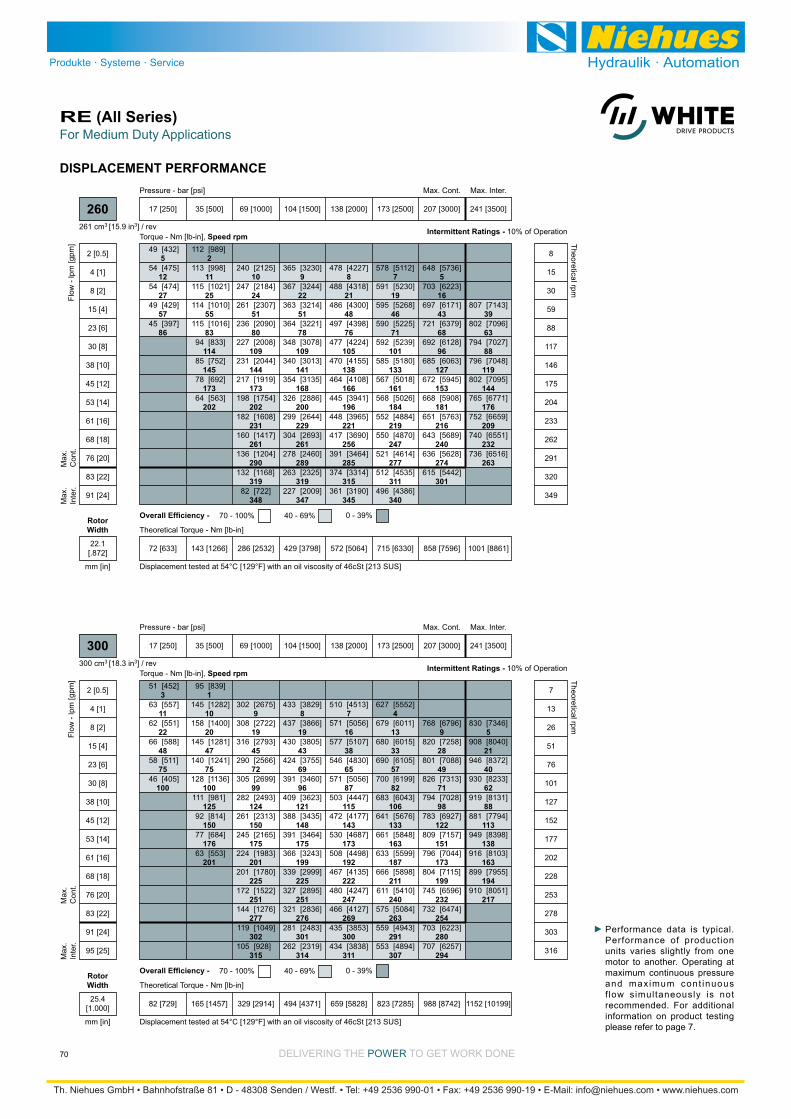
DELIVERING THE POWER TO GET WORK DONE
For Medium Duty ApplicationsRE (All Series)
70
DISPLACEMENT PERFORMANCE
5
12
27
57
86
2
11
25
55
83
114
145
173
202
10
24
51
80
109
144
173
202
231
261
290
319
348
9
22
51
78
109
141
168
200
229
261
289
319
347
8
21
48
76
105
138
166
196
221
256
285
315
345
7
19
46
71
101
133
161
184
219
247
277
311
340
5
16
43
68
96
127
153
181
216
240
274
301
39
63
88
119
144
176
209
232
263
[432]
[475]
[474]
[429]
[397]
49
54
54
49
45
[989]
[998]
[1021]
[1010]
[1016]
[833]
[752]
[692]
[563]
112
113
115
114
115
94
85
78
64
[2125]
[2184]
[2307]
[2090]
[2008]
[2044]
[1919]
[1754]
[1608]
[1417]
[1204]
[1168]
[722]
240
247
261
236
227
231
217
198
182
160
136
132
82
[3230]
[3244]
[3214]
[3221]
[3078]
[3013]
[3135]
[2886]
[2644]
[2693]
[2460]
[2325]
[2009]
365
367
363
364
348
340
354
326
299
304
278
263
227
[4227]
[4318]
[4300]
[4398]
[4224]
[4155]
[4108]
[3941]
[3965]
[3690]
[3464]
[3314]
[3190]
478
488
486
497
477
470
464
445
448
417
391
374
361
[5112]
[5230]
[5268]
[5225]
[5239]
[5180]
[5018]
[5026]
[4884]
[4870]
[4614]
[4535]
[4386]
578
591
595
590
592
585
567
568
552
550
521
512
496
[5736]
[6223]
[6171]
[6379]
[6128]
[6063]
[5945]
[5908]
[5763]
[5689]
[5628]
[5442]
648
703
697
721
692
685
672
668
651
643
636
615
[7143]
[7096]
[7027]
[7048]
[7095]
[6771]
[6659]
[6551]
[6516]
807
802
794
796
802
765
752
740
736
Torque - Nm [lb-in], Speed rpm
Flow
- lp
m [g
pm]
17 [250] 35 [500] 69 [1000] 104 [1500] 138 [2000] 173 [2500] 207 [3000] 241 [3500]
72 [633] 143 [1266] 286 [2532] 429 [3798] 572 [5064] 715 [6330] 858 [7596] 1001 [8861]
Theoretical Torque - Nm [lb-in]
Max
.In
ter.
Max
.C
ont.
260
2 [0.5]
4 [1]
8 [2]
15 [4]
23 [6]
30 [8]
38 [10]
45 [12]
53 [14]
61 [16]
68 [18]
76 [20]
83 [22]
91 [24]
8
15
30
59
88
117
146
175
204
233
262
291
320
349
Theoretical rpm
Overall Efficiency - 70 - 100% 40 - 69% 0 - 39%
Intermittent Ratings - 10% of Operation
Displacement tested at 54°C [129°F] with an oil viscosity of 46cSt [213 SUS]
Max. Inter.Max. Cont.Pressure - bar [psi]
261 cm3 [15.9 in3] / rev
mm [in]
RotorWidth
22.1[.872]
3
11
22
48
75
100
1
10
20
47
75
100
125
150
176
201
9
19
45
72
99
124
150
175
201
225
251
277
302
315
8
19
43
69
96
121
148
175
199
225
251
276
301
314
7
16
38
65
87
115
143
173
192
222
247
269
300
311
4
13
33
57
82
106
133
163
187
211
240
263
291
307
9
28
49
71
98
122
151
173
199
232
254
280
294
5
21
40
62
88
113
138
163
194
217
[452]
[557]
[551]
[588]
[511]
[405]
51
63
62
66
58
46
[839]
[1282]
[1400]
[1281]
[1241]
[1136]
[981]
[814]
[684]
[553]
95
145
158
145
140
128
111
92
77
63
[2675]
[2722]
[2793]
[2566]
[2699]
[2493]
[2313]
[2165]
[1983]
[1780]
[1522]
[1276]
[1049]
[928]
302
308
316
290
305
282
261
245
224
201
172
144
119
105
[3829]
[3866]
[3805]
[3755]
[3460]
[3623]
[3435]
[3464]
[3243]
[2999]
[2895]
[2836]
[2483]
[2319]
433
437
430
424
391
409
388
391
366
339
327
321
281
262
[4513]
[5056]
[5107]
[4830]
[5056]
[4447]
[4177]
[4687]
[4498]
[4135]
[4247]
[4127]
[3853]
[3838]
510
571
577
546
571
503
472
530
508
467
480
466
435
434
[5552]
[6011]
[6015]
[6105]
[6199]
[6043]
[5676]
[5848]
[5599]
[5898]
[5410]
[5084]
[4943]
[4894]
627
679
680
690
700
683
641
661
633
666
611
575
559
553
[6796]
[7258]
[7088]
[7313]
[7028]
[6927]
[7157]
[7044]
[7115]
[6596]
[6474]
[6223]
[6257]
768
820
801
826
794
783
809
796
804
745
732
703
707
[7346]
[8040]
[8372]
[8233]
[8131]
[7794]
[8398]
[8103]
[7955]
[8051]
830
908
946
930
919
881
949
916
899
910
Torque - Nm [lb-in], Speed rpm
Flow
- lp
m [g
pm]
17 [250] 35 [500] 69 [1000] 104 [1500] 138 [2000] 173 [2500] 207 [3000] 241 [3500]
Max. Inter.
82 [729] 165 [1457] 329 [2914] 494 [4371] 659 [5828] 823 [7285] 988 [8742] 1152 [10199]
Theoretical Torque - Nm [lb-in]
Max
.In
ter.
Max
.C
ont.
300
2 [0.5]
4 [1]
8 [2]
15 [4]
23 [6]
30 [8]
38 [10]
45 [12]
53 [14]
61 [16]
68 [18]
76 [20]
83 [22]
91 [24]
95 [25]
7
13
26
51
76
101
127
152
177
202
228
253
278
303
316
Theoretical rpm
Overall Efficiency - 70 - 100% 40 - 69% 0 - 39%
Intermittent Ratings - 10% of Operation
Displacement tested at 54°C [129°F] with an oil viscosity of 46cSt [213 SUS]
Max. Cont.Pressure - bar [psi]
300 cm3 [18.3 in3] / rev
mm [in]
RotorWidth
25.4[1.000]
Performance data is typical. Performance of production units varies slightly from one motor to another. Operating at maximum continuous pressure and maximum cont inuous f low simultaneously is not recommended. For additional information on product testing please refer to page 7.
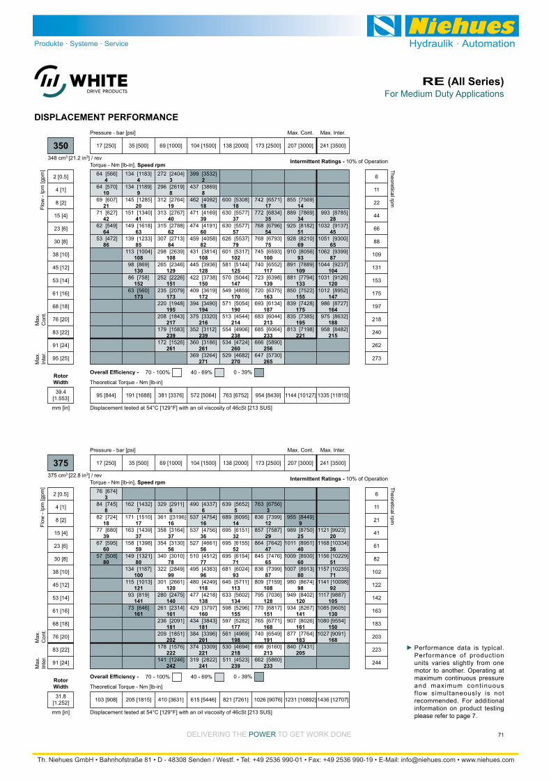
DELIVERING THE POWER TO GET WORK DONE
For Medium Duty ApplicationsRE (All Series)
71
DISPLACEMENT PERFORMANCE
4
10
21
42
64
86
4
9
20
41
63
85
108
130
152
173
3
8
19
40
62
84
108
129
151
173
195
217
239
261
2
8
18
39
60
82
108
128
150
172
194
216
239
261
271
18
37
57
79
102
125
147
170
190
214
238
260
270
17
35
54
75
100
117
139
163
187
213
233
256
265
14
34
51
69
93
109
133
155
175
195
221
28
45
65
87
104
120
147
164
188
215
[566]
[570]
[607]
[627]
[549]
[472]
64
64
69
71
62
53
[1183]
[1189]
[1285]
[1340]
[1618]
[1233]
[1004]
[869]
[758]
[560]
134
134
145
151
149
139
113
98
86
63
[2404]
[2619]
[2764]
[2767]
[2788]
[2713]
[2639]
[2346]
[2226]
[2079]
[1948]
[1843]
[1583]
[1526]
272
296
312
313
315
307
298
265
252
235
220
208
179
172
[3532]
[3869]
[4092]
[4169]
[4191]
[4058]
[3814]
[3936]
[3738]
[3619]
[3490]
[3320]
[3112]
[3186]
[3264]
399
437
462
471
474
459
431
445
422
409
394
375
352
360
369
[5308]
[5577]
[5577]
[5537]
[5317]
[5144]
[5044]
[4859]
[5054]
[4544]
[4906]
[4724]
[4682]
600
630
630
626
601
581
570
549
571
513
554
534
529
[6571]
[6834]
[6796]
[6793]
[6593]
[6552]
[6398]
[6375]
[6134]
[6044]
[6064]
[5890]
[5730]
742
772
768
768
745
740
723
720
693
683
685
666
647
[7569]
[7869]
[8182]
[8210]
[8056]
[7889]
[7794]
[7522]
[7428]
[7385]
[7198]
855
889
925
928
910
891
881
850
839
835
813
[8785]
[9137]
[9300]
[9399]
[9237]
[9126]
[8952]
[8727]
[8632]
[8482]
993
1032
1051
1062
1044
1031
1012
986
975
958
Torque - Nm [lb-in], Speed rpm
Flow
- lp
m [g
pm]
17 [250] 35 [500] 69 [1000] 104 [1500] 138 [2000] 173 [2500] 207 [3000] 241 [3500]
Max. Inter.
95 [844] 191 [1688] 381 [3376] 572 [5064] 763 [6752] 954 [8439] 1144 [10127] 1335 [11815]
Theoretical Torque - Nm [lb-in]
Max
.In
ter.
Max
.C
ont.
350
2 [0.5]
4 [1]
8 [2]
15 [4]
23 [6]
30 [8]
38 [10]
45 [12]
53 [14]
61 [16]
68 [18]
76 [20]
83 [22]
91 [24]
95 [25]
6
11
22
44
66
88
109
131
153
175
197
218
240
262
273
Theoretical rpm
Overall Efficiency - 70 - 100% 40 - 69% 0 - 39%
Intermittent Ratings - 10% of Operation
Displacement tested at 54°C [129°F] with an oil viscosity of 46cSt [213 SUS]
Max. Cont.Pressure - bar [psi]
348 cm3 [21.2 in3] / rev
mm [in]
RotorWidth
39.4[1.553]
3
8
18
39
60
80
7
17
37
59
80
100
121
141
161
6
16
37
56
78
99
120
140
161
181
202
222
242
6
16
36
56
77
96
118
138
160
181
201
221
241
5
14
32
52
71
93
113
134
155
177
198
218
239
3
12
29
47
65
87
108
128
151
168
191
213
233
9
25
40
60
80
98
120
141
161
183
205
20
36
51
71
92
105
130
150
168
[674]
[745]
[724]
[680]
[595]
[508]
76
84
82
77
67
57
[1432]
[1510]
[1439]
[1398]
[1321]
[1187]
[1013]
[819]
[646]
162
171
163
158
149
134
115
93
73
[2911]
[[3196]
[3164]
[3130]
[3010]
[2849]
[2661]
[2475]
[2314]
[2091]
[1851]
[1576]
[1246]
329
361
358
354
340
322
301
280
261
236
209
178
141
[4337]
[4754]
[4756]
[4661]
[4512]
[4383]
[4249]
[4218]
[3797]
[3843]
[3396]
[3309]
[2822]
490
537
537
527
510
495
480
477
429
434
384
374
319
[5652]
[6095]
[6151]
[6155]
[6154]
[6024]
[5711]
[5602]
[5296]
[5282]
[4969]
[4694]
[4523]
639
689
695
695
695
681
645
633
598
597
561
530
511
[6756]
[7399]
[7587]
[7642]
[7476]
[7399]
[7159]
[7036]
[6817]
[6771]
[6549]
[6160]
[5860]
763
836
857
864
845
836
809
795
770
765
740
696
662
[8449]
[8750]
[8951]
[8930]
[8913]
[8674]
[8402]
[8267]
[8026]
[7764]
[7431]
955
989
1011
1009
1007
980
949
934
907
877
840
[9923]
[10334]
[10229]
[10235]
[10098]
[9887]
[9605]
[9554]
[9091]
1121
1168
1156
1157
1141
1117
1085
1080
1027
Torque - Nm [lb-in], Speed rpm
Flow
- lp
m [g
pm]
17 [250] 35 [500] 69 [1000] 104 [1500] 138 [2000] 173 [2500] 207 [3000] 241 [3500]
Max. Inter.Max. Cont.
103 [908] 205 [1815] 410 [3631] 615 [5446] 821 [7261] 1026 [9076] 1231 [10892] 1436 [12707]
Theoretical Torque - Nm [lb-in]
Max
.In
ter.
Max
.C
ont.
375
2 [0.5]
4 [1]
8 [2]
15 [4]
23 [6]
30 [8]
38 [10]
45 [12]
53 [14]
61 [16]
68 [18]
76 [20]
83 [22]
91 [24]
6
11
21
41
61
82
102
122
142
163
183
203
223
244
Theoretical rpm
Overall Efficiency - 70 - 100% 40 - 69% 0 - 39%
Intermittent Ratings - 10% of Operation
Displacement tested at 54°C [129°F] with an oil viscosity of 46cSt [213 SUS]
Pressure - bar [psi]
375 cm3 [22.8 in3] / rev
mm [in]
RotorWidth
31.8[1.252]
Performance data is typical. Performance of production units varies slightly from one motor to another. Operating at maximum continuous pressure and maximum cont inuous f low simultaneously is not recommended. For additional information on product testing please refer to page 7.
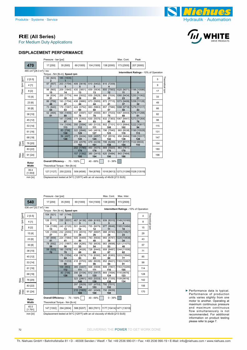
DELIVERING THE POWER TO GET WORK DONE
For Medium Duty ApplicationsRE (All Series)
72
DISPLACEMENT PERFORMANCE
2
7
15
31
48
64
81
1
5
14
30
47
63
80
97
113
130
146
5
13
28
44
60
78
94
112
129
145
162
179
195
5
13
28
44
60
78
93
111
127
145
161
178
194
4
12
26
41
57
75
90
108
123
142
158
176
190
11
23
37
50
68
83
102
119
138
154
170
186
9
21
32
43
61
76
94
113
128
143
[823]
[857]
[865]
[834]
[759]
[643]
[464]
93
97
98
94
86
73
52
[1635]
[1794]
[1845]
[1774]
[1704]
[1587]
[1455]
[1248]
[1006]
[736]
[497]
185
203
209
200
193
179
164
141
114
83
56
[3618]
[3851]
[3932]
[3880]
[3752]
[3597]
[3350]
[3094]
[2846]
[2434]
[2078]
[1790]
[1392]
409
435
444
438
424
407
379
350
322
275
235
202
157
[5402]
[5836]
[5829]
[5955]
[5863]
[5550]
[5575]
[5133]
[4819]
[4657]
[4239]
[4075]
[3410]
610
659
659
673
663
627
630
580
545
526
479
460
385
[7209]
[7563]
[7836]
[7715]
[7586]
[7533]
[7363]
[7101]
[7040]
[6519]
[6249]
[5920]
[5484]
815
855
886
872
857
851
832
802
796
737
706
669
620
[9071]
[9434]
[9499]
[9718]
[9444]
[9441]
[8964]
[8538]
[8464]
[8117]
[7811]
[7464]
1025
1066
1073
1098
1067
1067
1013
965
956
917
883
843
[10586]
[11062]
[11128]
[11317]
[11288]
[11264]
[10817]
[10528]
[10317]
[9933]
1196
1250
1258
1279
1276
1273
1222
1190
1166
1122
Torque - Nm [lb-in], Speed rpm
Flow
- lp
m [g
pm]
17 [250] 35 [500] 69 [1000] 104 [1500] 138 [2000] 173 [2500] 207 [3000]
PeakMax. Cont.
127 [1127] 255 [2253] 509 [4506] 764 [6760] 1018 [9013] 1273 [11266] 1528 [13519]
Theoretical Torque - Nm [lb-in]
Max
.In
ter.
Max
.C
ont.
470
2 [0.5]
4 [1]
8 [2]
15 [4]
23 [6]
30 [8]
38 [10]
45 [12]
53 [14]
61 [16]
68 [18]
76 [20]
83 [22]
91 [24]
5
9
17
33
49
66
82
98
115
131
147
164
180
196
Theoretical rpm
Overall Efficiency - 70 - 100% 40 - 69% 0 - 39%
Intermittent Ratings - 10% of Operation
Displacement tested at 54°C [129°F] with an oil viscosity of 46cSt [213 SUS]
Pressure - bar [psi]
465 cm3 [28.3 in3] / rev
mm [in]
RotorWidth
39.4[1.553]
2
6
13
27
41
56
70
2
5
13
27
41
56
70
84
98
112
126
5
12
26
40
55
69
83
97
111
126
140
154
169
5
12
26
40
54
69
83
96
111
125
139
153
168
5
11
24
38
53
67
80
94
110
124
138
152
168
4
10
23
34
48
62
77
91
105
123
134
[921]
[1111]
[1189]
[1058]
[859]
[692]
[523]
104
126
134
120
97
78
59
[1748]
[2031]
[2120]
[2055]
[1984]
[1887]
[1678]
[1554]
[1233]
[963]
[736]
197
230
240
232
224
213
190
176
139
109
83
[4136]
[4436]
[4510]
[4469]
[4285]
[4026]
[3879]
[3703]
[3407]
[3154]
[2861]
[2629]
[1905]
467
501
510
505
484
455
438
418
385
356
323
297
215
[6183]
[6679]
[6697]
[6930]
[6635]
[6445]
[6360]
[6035]
[5908]
[5417]
[5333]
[4753]
[4349]
699
755
757
783
750
728
719
682
668
612
603
537
491
[8310]
[8646]
[8740]
[8787]
[8698]
[8487]
[8360]
[8421]
[7957]
[7694]
[7335]
[7011]
[6639]
939
977
988
993
983
959
945
952
899
869
829
792
750
[10165]
[10484]
[10827]
[10838]
[11075]
[11008]
[10646]
[10467]
[10290]
[9876]
[9816]
1149
1185
1223
1225
1251
1244
1203
1183
1163
1116
1109
Torque - Nm [lb-in], Speed rpm
Flow
- lp
m [g
pm]
17 [250] 35 [500] 69 [1000] 104 [1500] 138 [2000] 173 [2500]
Max. Inter.Max. Cont.
147 [1302] 294 [2604] 588 [5207] 883 [7811] 1177 [10414] 1471 [13018]
Theoretical Torque - Nm [lb-in]
Max
.In
ter.
Max
.C
ont.
540
2 [0.5]
4 [1]
8 [2]
15 [4]
23 [6]
30 [8]
38 [10]
45 [12]
53 [14]
61 [16]
68 [18]
76 [20]
83 [22]
91 [24]
4
8
15
29
43
57
71
85
99
114
128
142
156
170
Theoretical rpm
Overall Efficiency - 70 - 100% 40 - 69% 0 - 39%
Intermittent Ratings - 10% of Operation
Displacement tested at 54°C [129°F] with an oil viscosity of 46cSt [213 SUS]
Pressure - bar [psi]
536 cm3 [32.7 in3] / rev
mm [in]
RotorWidth
45.5[1.791]
Performance data is typical. Performance of production units varies slightly from one motor to another. Operating at maximum continuous pressure and maximum cont inuous f low simultaneously is not recommended. For additional information on product testing please refer to page 7.

DELIVERING THE POWER TO GET WORK DONE
For Medium Duty ApplicationsRE (All Series)
73
DISPLACEMENT PERFORMANCE
2
4
9
19
29
40
50
60
1
4
9
19
29
40
49
60
70
80
90
100
4
9
19
28
39
49
59
69
79
90
100
110
121
3
8
18
28
38
48
59
68
78
89
99
110
120
3
7
16
26
34
47
56
67
76
88
98
[1299]
[1379]
[1403]
[1350]
[1194]
[1008]
[722]
[477]
147
156
158
153
135
114
82
54
[2487]
[2852]
[3003]
[2933]
[2840]
[2690]
[2395]
[2207]
[1739]
[1325]
[927]
[552]
281
322
339
331
321
304
271
249
197
150
105
62
[5768]
[6134]
[6241]
[6166]
[6002]
[5733]
[5452]
[5104]
[4718]
[4374]
[3741]
[3404]
[2669]
652
693
705
697
678
648
616
577
533
494
423
385
302
[8554]
[9088]
[9419]
[9373]
[9197]
[8980]
[8699]
[8372]
[8008]
[7614]
[7123]
[6608]
[5932]
967
1027
1064
1059
1039
1015
983
946
905
860
805
747
670
[11571]
[12033]
[12534]
[12462]
[12573]
[12130]
[11902]
[11600]
[11249]
[10843]
[10385]
1308
1360
1416
1408
1421
1371
1345
1311
1271
1225
1173
Torque - Nm [lb-in], Speed rpm
Flow
- lp
m [g
pm]
17 [250] 35 [500] 69 [1000] 104 [1500] 138 [2000]
PeakMax. Cont.
205 [1815] 410 [3631] 821 [7261] 1231 [10892] 1641 [14522]
Theoretical Torque - Nm [lb-in]
Max
.In
ter.
Max
.C
ont.
750
2 [0.5]
4 [1]
8 [2]
15 [4]
23 [6]
30 [8]
38 [10]
45 [12]
53 [14]
61 [16]
68 [18]
76 [20]
83 [22]
91 [24]
3
6
11
21
31
41
51
61
71
82
92
102
112
122
Theoretical rpm
Overall Efficiency - 70 - 100% 40 - 69% 0 - 39%
Intermittent Ratings - 10% of Operation
Displacement tested at 54°C [129°F] with an oil viscosity of 46cSt [213 SUS]
Pressure - bar [psi]
748 cm3 [45.6 in3] / rev
mm [in]
RotorWidth
63.5[2.501]
Performance data is typical. Performance of production units varies slightly from one motor to another. Operating at maximum continuous pressure and maximum cont inuous f low simultaneously is not recommended. For additional information on product testing please refer to page 7.
2
5
11
23
35
47
59
1
5
11
23
35
47
58
71
83
95
107
5
11
23
34
46
58
70
81
94
107
119
131
143
4
10
22
34
45
57
70
80
93
106
118
131
142
3
9
21
33
44
56
69
79
92
105
117
130
141
7
17
29
40
52
65
78
90
104
115
[1060]
[1202]
[1256]
[1159]
[982]
[809]
[595]
120
136
142
131
111
91
67
[2021]
[2332]
[2445]
[2379]
[2300]
[2184]
[1943]
[1794]
[1419]
[1095]
[801]
228
264
276
269
260
247
220
203
160
124
91
[4733]
[5055]
[5141]
[5087]
[4914]
[4655]
[4456]
[4213]
[3885]
[3599]
[3172]
[2901]
[2185]
535
571
581
575
555
526
504
476
439
407
358
328
247
[7048]
[7550]
[7696]
[7811]
[7570]
[7372]
[7208]
[6888]
[6666]
[6223]
[5974]
[5431]
[4922]
796
853
870
883
855
833
815
778
753
703
675
614
556
[8275]
[8717]
[8920]
[8976]
[8853]
[8602]
[8437]
[8233]
[7917]
[7537]
[7215]
[6715]
[6249]
935
985
1008
1014
1000
972
953
930
895
852
815
759
706
[11117]
[11320]
[11368]
[11421]
[11225]
[10977]
[10843]
[10509]
[10147]
[9736]
1256
1279
1285
1291
1268
1240
1225
1187
1147
1100
Torque - Nm [lb-in], Speed rpm
Flow
- lp
m [g
pm]
17 [250] 35 [500] 69 [1000] 104 [1500] 121 [1750] 155 [2250]
Max. Inter.Max. Cont.
173 [1532] 346 [3064] 692 [6127] 1039 [9191] 1212 [10729] 1559 [13794]
Theoretical Torque - Nm [lb-in]
Max
.In
ter.
Max
.C
ont.
620
2 [0.5]
4 [1]
8 [2]
15 [4]
23 [6]
30 [8]
38 [10]
45 [12]
53 [14]
61 [16]
68 [18]
76 [20]
83 [22]
91 [24]
3
6
12
24
36
48
60
72
84
96
108
120
132
144
Theoretical rpm
Overall Efficiency - 70 - 100% 40 - 69% 0 - 39%
Intermittent Ratings - 10% of Operation
Displacement tested at 54°C [129°F] with an oil viscosity of 46cSt [213 SUS]
Pressure - bar [psi]
631 cm3 [38.5 in3] / rev
mm [in]
RotorWidth
54.0[2.125]

Medium Duty Hydraulic MotorRE (505/506 Series)
74 DELIVERING THE POWER TO GET WORK DONE
HOUSINGS
Dimension II is charted on page 76.
13.7 [.539]13.5 [.530]
82.6 [3.250]82.5 [3.247]
18 [.70] Max.
127.0 [4.999]126.8 [4.996]
3.0 [.120]2.8 [.110]
136 [5.35] Max.
Ø 106.3 [4.187]
22.5° 62 [2.43] Min.
62 [2.43] Max. 66 [2.58] Max.
23 [.90]
23 [.90]
61 [2.39]
A
B
II
3 [.12]
2 [.06]
13.7 [.539]13.5 [.530]
82.6 [3.250]82.5 [3.247]
18 [.70] Max.
127.0 [4.999]126.8 [4.996]
3.0 [.120]2.8 [.110]
136 [5.35] Max.
Ø 106.3 [4.187]
22.5° 62 [2.43] Min.
62 [2.43] Max. 66 [2.58] Max.
23 [.90]
23 [.90]
61 [2.39]
A
B
60 [2.35] Min.
114 [4.49]
64 [2.52]
Ø31 [1.24] Spot Face
II
EFB
A
3 [.12]
2 [.06]
23 [.91]
A38 G 1/24-HOLE, MAGNETO MOUNT, ALIGNED PORTS A31 7/8-14 UNF
A58 G 1/26-HOLE, SAE A MOUNT, ALIGNED PORTS A51 7/8-14 UNF
E: 10 Series/2-Way Valve Cavity 7/8-14 UNF F: Valve Cartridge Installed
STANDARD
OPTIONAL VALVE CAVITY
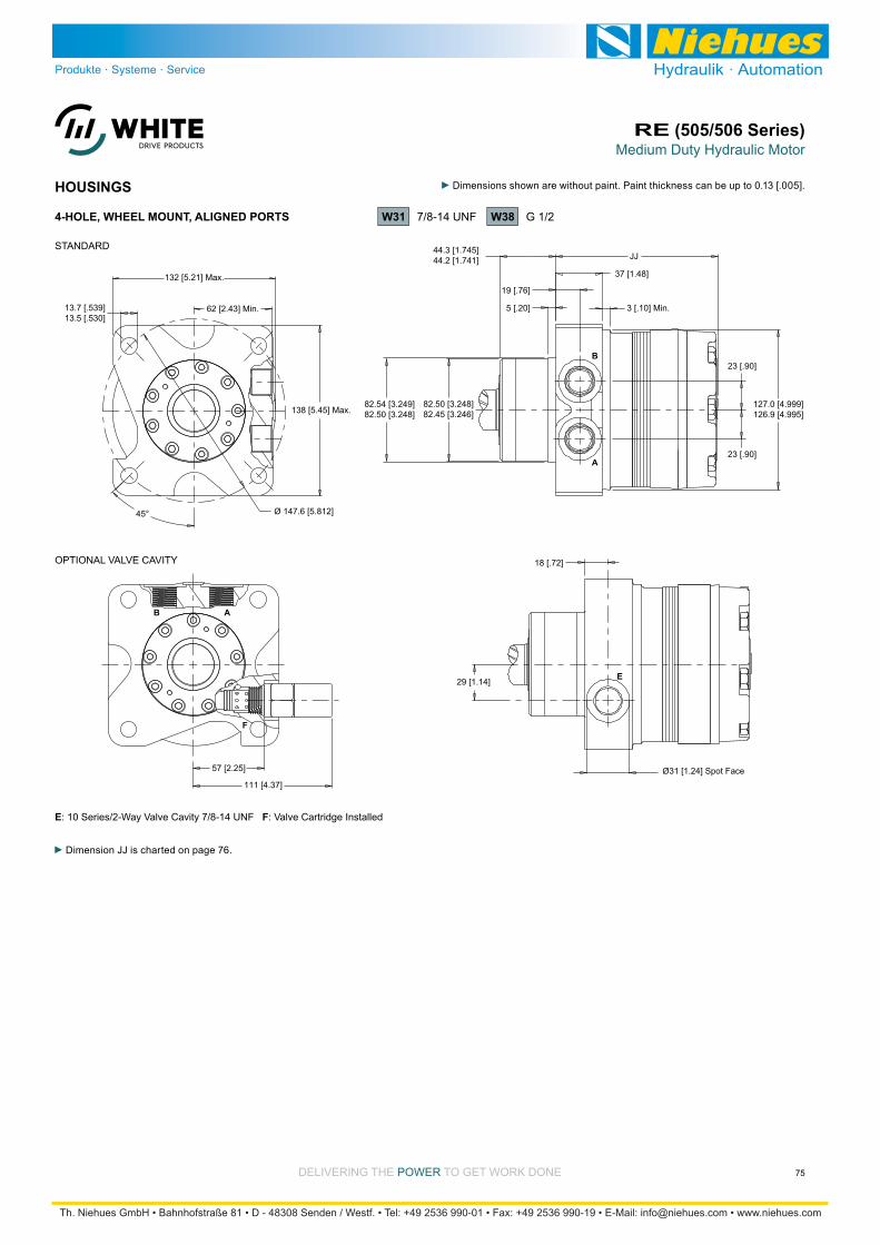
Medium Duty Hydraulic MotorRE (505/506 Series)
75DELIVERING THE POWER TO GET WORK DONE
HOUSINGS
Dimension JJ is charted on page 76.
13.7 [.539]13.5 [.530]
82.54 [3.249]82.50 [3.248]
23 [.90]
5 [.20]
127.0 [4.999]126.9 [4.995]
44.3 [1.745]44.2 [1.741]
138 [5.45] Max.
Ø 147.6 [5.812]45°
62 [2.43] Min.
132 [5.21] Max.
23 [.90]
3 [.10] Min.
37 [1.48]
A
B
57 [2.25]
111 [4.37]
18 [.72]
29 [1.14]
JJ
E
F
B A
19 [.76]
82.50 [3.248]82.45 [3.246]
Ø31 [1.24] Spot Face
W38 G 1/24-HOLE, WHEEL MOUNT, ALIGNED PORTS W31 7/8-14 UNF
E: 10 Series/2-Way Valve Cavity 7/8-14 UNF F: Valve Cartridge Installed
STANDARD
OPTIONAL VALVE CAVITY
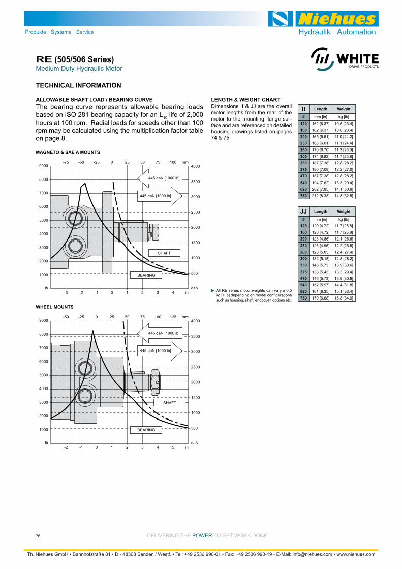
Medium Duty Hydraulic MotorRE (505/506 Series)
76 DELIVERING THE POWER TO GET WORK DONE
TECHNICAL INFORMATION
3000
9000
MAGNETO & SAE A MOUNTS
7000
8000
6000
5000
4000
lb
2000
1000
1000
4000
3000
3500
2500
2000
1500
daN
500
3 in4-3 21-2 0-1
75 mm1005025-75 -50 0-25
445 daN [1000 lb]
445 daN [1000 lb]
BEARING
SHAFT
The bearing curve represents allowable bearing loads based on ISO 281 bearing capacity for an L10 life of 2,000 hours at 100 rpm. Radial loads for speeds other than 100 rpm may be calculated using the multiplication factor table on page 8.
ALLOWABLE SHAFT LOAD / BEARING CURVE LENGTH & WEIGHT CHARTDimensions II & JJ are the overall motor lengths from the rear of the
-face and are referenced on detailed housing drawings listed on pages 74 & 75.
All RE series motor weights can vary ± 0.5
such as housing, shaft, endcover, options etc.
3000
9000
WHEEL MOUNTS
7000
8000
6000
5000
4000
lb
2000
1000
1000
4000
3000
3500
2500
2000
1500
daN
500
4 in5-2 32-1 10
100 mm1257550-50 -25 250
445 daN [1000 lb]
445 daN [1000 lb]
BEARING
SHAFT
Length Weight
#120160200230260300350375470540620750
kg [lb]
10.6 [23.4]
10.6 [23.4]
11.0 [24.2]
11.1 [24.4]
11.3 [25.0]
11.7 [25.8]
12.8 [28.2]
12.2 [27.0]
12.8 [28.2]
13.3 [29.4]
14.1 [30.9]
14.8 [32.5]
mm [in]
162 [6.37]
162 [6.37]
165 [6.51]
168 [6.61]
170 [6.70]
174 [6.83]
187 [7.38]
180 [7.08]
187 [7.38]
194 [7.62]
202 [7.95]
212 [8.33]
II
Length Weight
#120160200230260300350375470540620750
kg [lb]
11.7 [25.8]
11.7 [25.8]
12.1 [26.6]
12.2 [26.8]
12.4 [27.4]
12.8 [28.2]
13.9 [30.6]
13.3 [29.4]
13.9 [30.6]
14.4 [31.8]
15.1 [33.4]
15.8 [34.9]
mm [in]
120 [4.72]
120 [4.72]
123 [4.86]
126 [4.95]
128 [5.05]
132 [5.18]
146 [5.73]
138 [5.43]
146 [5.73]
152 [5.97]
161 [6.35]
170 [6.68]
JJ

Medium Duty Hydraulic MotorRE (505/506 Series)
77DELIVERING THE POWER TO GET WORK DONE
SHAFTS
32.0 [1.260]32.0 [1.259]
KK
54 [2.14]
M8x1.25, Min. Depth 16 [.63]
34.8 [1.372]34.5 [1.359]
32.6 [1.285]31.4 [1.235]
48 [1.90]
12 [.46]10.0 [.394]10.0 [.392]
KK
35 [1.37]
19 [.75]
5 [.20]
4 [.15]
8.0 [.314]8.0 [.313] 24.3 [.957]
23.0 [.907]
1:8 TaperØ4 [.17]
31.8 [1.250]31.7 [1.249]
5 [.21]
30.9 [1.218]29.7 [1.168]8.0 [.314]
8.0 [.313]
28.0 [1.102]27.7 [1.091]
Ø25.0 [.984]Ø25.0 [.983]
KK
M8x1.25, Min. Depth 16 [.63]
46 [1.83]
5 [.18]
25.9 [1.020]24.6 [.970]6.4 [.251]
6.4 [.250]
31.8 [1.250]31.7 [1.249]
25 [1.00]
5/16-18 UNC, Min. Depth 18 [.70]
28.2 [1.110]28.0 [1.101]
Ø25.4 [.999]Ø25.3 [.998]
Ø25.3 [.996]Ø25.2 [.992]
40 [1.58]
KK
KK54 [2.14]
KK
5/8-18 UNF, Min. Depth 21 [.83]
5/16-18 UNC, Min. Depth 18 [.70]
40 [1.58]
6B SplineSAE J499 Standard
35.3 [1.388]35.0 [1.376]
37.5 [1.475]36.2 [1.425]
48 [1.90]
8 [.33]8.0 [.314]8.0 [.313]
31.7 [1.249]31.6 [1.245]
KK
54 [2.14]
5/8-18 UNF, Min. Depth 21 [.83] Ø2 [.06]
33 [1.31]Wire Ring
48 [1.90]
41 [1.60]
14 Tooth Spline 12/24 PitchStandard ANSI B92.1-1996 Spline
02 1” 6B Spline
Max. Torque: 678 Nm [6000 lb-in]
Max. Torque: 1200 Nm [10600 lb-in]
07 1-1/4” Straight Extended
22 1-1/4” Tapered
09 14 Tooth Spline Extended
Max. Torque: 1200 Nm [10600 lb-in]
Max. Torque: 655 Nm [5800 lb-in]
20 1-1/4” Straight
03 1” 6B Spline Extended
12 25mm Straight
Max. Torque: 678 Nm [6000 lb-in]
08 32mm Straight Extended 21 32mm Straight
23 14 Tooth Spline
10 1” Straight 15 1” Straight Extended
25 1-1/4” Tapered Extended
Max. Torque: 1200 Nm [10600 lb-in]
Max. Torque: 1200 Nm [10600 lb-in]
A slotted hex nut is standard on this shaft.
Magneto &A Mounts
WheelMountsKK
#02030708091012152021222325
mm [in]
50 [1.97]
76 [3.01]
88 [3.45]
88 [3.45]
88 [3.45]
50 [1.97]
56 [2.21]
76 [3.01]
61 [2.41]
61 [2.41]
66 [2.58]
61 [2.41]
92 [3.62]
mm [in]
91 [3.60]
118 [4.64]
129 [5.09]
129 [5.09]
129 [5.09]
91 [3.60]
98 [3.84]
118 [4.64]
103 [4.05]
103 [4.05]
107 [4.22]
103 [4.05]
134 [5.26]
MOUNTING / SHAFT LENGTH CHART
Dimension KK is the overall dis-tance from the motor mounting surface to the end of the shaft and is referenced on detailed shaft draw-ings above.
Shaft lengths vary ± 0.8 mm [.030 in.]
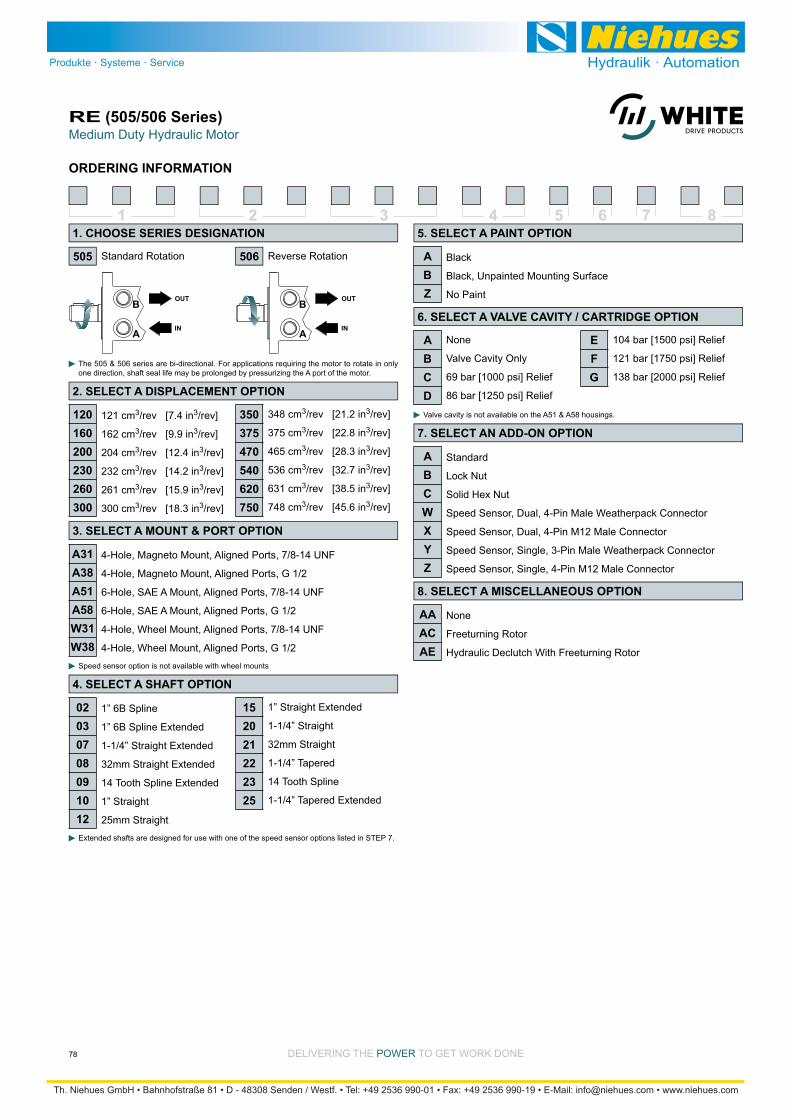
Medium Duty Hydraulic MotorRE (505/506 Series)
78 DELIVERING THE POWER TO GET WORK DONE
ORDERING INFORMATION
1 2 3 4 5 6 7 8
Standard Rotation Reverse Rotation
The 505 & 506 series are bi-directional. For applications requiring the motor to rotate in only one direction, shaft seal life may be prolonged by pressurizing the A port of the motor.
4-Hole, Magneto Mount, Aligned Ports, 7/8-14 UNF
4-Hole, Magneto Mount, Aligned Ports, G 1/2
6-Hole, SAE A Mount, Aligned Ports, 7/8-14 UNF
6-Hole, SAE A Mount, Aligned Ports, G 1/2
4-Hole, Wheel Mount, Aligned Ports, 7/8-14 UNF
4-Hole, Wheel Mount, Aligned Ports, G 1/2
1” 6B Spline
1” 6B Spline Extended
1-1/4” Straight Extended
32mm Straight Extended
14 Tooth Spline Extended
1” Straight
25mm Straight
1” Straight Extended
1-1/4” Straight
32mm Straight
1-1/4” Tapered
14 Tooth Spline
1-1/4” Tapered Extended
Black
Black, Unpainted Mounting Surface
No Paint
Standard
Lock Nut
Solid Hex Nut
Speed Sensor, Dual, 4-Pin Male Weatherpack Connector
Speed Sensor, Dual, 4-Pin M12 Male Connector
Speed Sensor, Single, 3-Pin Male Weatherpack Connector
Speed Sensor, Single, 4-Pin M12 Male Connector
Extended shafts are designed for use with one of the speed sensor options listed in STEP 7.
Speed sensor option is not available with wheel mounts
None
Valve Cavity Only
69 bar [1000 psi] Relief
86 bar [1250 psi] Relief
104 bar [1500 psi] Relief
121 bar [1750 psi] Relief
138 bar [2000 psi] Relief
Valve cavity is not available on the A51 & A58 housings.121 cm3/rev [7.4 in3/rev]
162 cm3/rev [9.9 in3/rev]
204 cm3/rev [12.4 in3/rev]
232 cm3/rev [14.2 in3/rev]
261 cm3/rev [15.9 in3/rev]
300 cm3/rev [18.3 in3/rev]
348 cm3/rev [21.2 in3/rev]
375 cm3/rev [22.8 in3/rev]
465 cm3/rev [28.3 in3/rev]
536 cm3/rev [32.7 in3/rev]
631 cm3/rev [38.5 in3/rev]
748 cm3/rev [45.6 in3/rev]
None
Freeturning Rotor
Hydraulic Declutch With Freeturning Rotor
505
1. CHOOSE SERIES DESIGNATION
2. SELECT A DISPLACEMENT OPTION
3. SELECT A MOUNT & PORT OPTION
A31A38A51A58W31W38
4. SELECT A SHAFT OPTION
02030708091012
152021222325
5. SELECT A PAINT OPTION
ABZ
6. SELECT A VALVE CAVITY / CARTRIDGE OPTION
7. SELECT AN ADD-ON OPTION
ABCWXYZ
8. SELECT A MISCELLANEOUS OPTION
AAACAE
506
ABCD
EFG
120160200230260300
350375470540620750
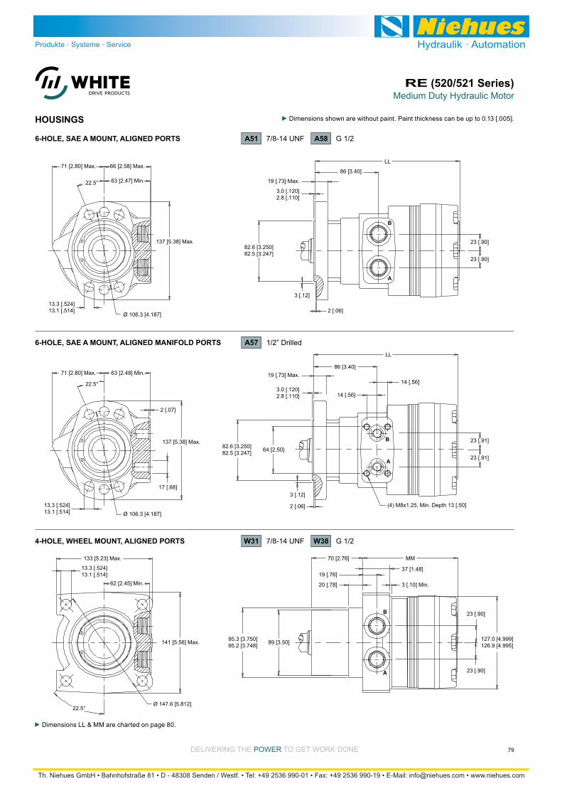
Medium Duty Hydraulic MotorRE (520/521 Series)
79DELIVERING THE POWER TO GET WORK DONE
HOUSINGS
Dimensions LL & MM are charted on page 80.
13.3 [.524]13.1 [.514]
95.3 [3.750]95.2 [3.748]
127.0 [4.999]126.9 [4.995]
20 [.78]
141 [5.56] Max.
Ø 147.6 [5.812]22.5°
62 [2.45] Min.
133 [5.23] Max. 70 [2.76]
A
B
MM
3 [.10] Min.
37 [1.48]
13.3 [.524]13.1 [.514]
82.6 [3.250]82.5 [3.247]
19 [.73] Max.
3.0 [.120]2.8 [.110]
137 [5.38] Max.
Ø 106.3 [4.187]
22.5° 63 [2.47] Min.
71 [2.80] Max. 66 [2.58] Max.
13.3 [.524]13.1 [.514]
137 [5.38] Max.
Ø 106.3 [4.187]
22.5°
63 [2.48] Min.71 [2.80] Max.
23 [.90]
23 [.90]
86 [3.40]
A
B
14 [.56]
LL
3 [.12]
2 [.06]
82.6 [3.250]82.5 [3.247]
19 [.73] Max.
3.0 [.120]2.8 [.110]
23 [.91]
23 [.91]
23 [.90]
23 [.90]
86 [3.40]
A
B
LL
3 [.12]
2 [.06]
17 [.68]
2 [.07]
14 [.56]
(4) M8x1.25, Min. Depth 13 [.50]
19 [.76]
89 [3.50]
64 [2.50]
A58 G 1/26-HOLE, SAE A MOUNT, ALIGNED PORTS A51 7/8-14 UNF
W38 G 1/24-HOLE, WHEEL MOUNT, ALIGNED PORTS W31 7/8-14 UNF
6-HOLE, SAE A MOUNT, ALIGNED MANIFOLD PORTS A57 1/2” Drilled

Medium Duty Hydraulic MotorRE (520/521 Series)
80 DELIVERING THE POWER TO GET WORK DONE
TECHNICAL INFORMATION
3000
11000
SAE A MOUNTS
7000
9000
10000
8000
6000
5000
4000
lb
2000
1000
1000
4500
3000
3500
4000
2500
2000
1500
daN
500
3 in4-3 21*2 0-1
75 mm1005025-75 -50 0-25
445 daN [1000 lb]
445 daN [1000 lb]
BEARING
SHAFT
The bearing curve represents allowable bearing loads based on ISO 281 bearing capacity for an L10 life of 2,000 hours at 100 rpm. Radial loads for speeds other than 100 rpm may be calculated using the multiplication factor table on page 8.
ALLOWABLE SHAFT LOAD / BEARING CURVE LENGTH & WEIGHT CHARTDimensions LL & MM are the overall motor lengths from the rear of the
-face and are referenced on detailed housing drawings listed on page 79.
All RE series motor weights can vary ± 0.5
such as housing, shaft, endcover, options etc.
3000
11000
WHEEL MOUNTS
7000
9000
10000
8000
6000
5000
4000
lb
2000
1000
1000
4500
3000
3500
4000
2500
2000
1500
daN
500
5 in6-1 430 21
125 mm15010075-25 0 5025
445 daN [1000 lb]
445 daN [1000 lb]
BEARING
SHAFT
Length Weight
#120160200230260300350375470540620750
kg [lb]
13.3 [29.4]
13.3 [29.4]
13.7 [30.2]
13.8 [30.4]
14.1 [31.0]
14.4 [31.8]
15.5 [34.2]
15.0 [33.0]
15.5 [34.2]
16.1 [35.4]
16.8 [36.9]
17.5 [38.5]
mm [in]
187 [7.37]
187 [7.37]
191 [7.51]
193 [7.61]
196 [7.70]
199 [7.83]
213 [8.38]
205 [8.08]
213 [8.38]
219 [8.62]
227 [8.95]
237 [9.33]
LL
Length Weight
#120160200230260300350375470540620750
kg [lb]
12.9 [28.4]
12.9 [28.4]
13.2 [29.2]
13.3 [29.4]
13.6 [30.0]
14.0 [30.8]
15.1 [33.2]
14.5 [32.0]
15.1 [33.2]
15.6 [34.4]
16.3 [35.9]
17.0 [37.5]
mm [in]
120 [4.72]
120 [4.72]
123 [4.86]
126 [4.95]
128 [5.05]
132 [5.18]
146 [5.73]
138 [5.43]
146 [5.73]
152 [5.97]
160 [6.30]
170 [6.68]
MM
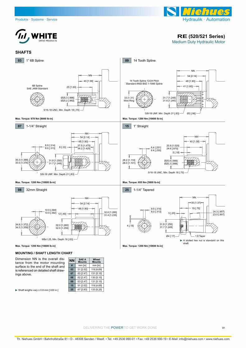
Medium Duty Hydraulic MotorRE (520/521 Series)
81DELIVERING THE POWER TO GET WORK DONE
SHAFTS
SAE A Mounts
WheelMountsNN
#030708091525
mm [in]
51 [2.02]
63 [2.47]
62 [2.47]
63 [2.47]
51 [2.02]
67 [2.63]
mm [in]
119 [4.69]
131 [5.15]
130 [5.15]
131 [5.15]
119 [4.69]
133 [5.25]
MOUNTING / SHAFT LENGTH CHART
Dimension NN is the overall dis-tance from the motor mounting surface to the end of the shaft and is referenced on detailed shaft draw-ings above.
Shaft lengths vary ± 0.8 mm [.030 in.]
32.0 [1.260]32.0 [1.259]
NN
54 [2.14]
M8x1.25, Min. Depth 16 [.63]
34.8 [1.372]34.5 [1.359]
32.6 [1.285]31.4 [1.235]
48 [1.90]
12 [.46]10.0 [.394]10.0 [.392]
NN
35 [1.37]
19 [.75]
5 [.20]
4 [.15]
8.0 [.314]8.0 [.313] 24.3 [.957]
23.0 [.907]
1:8 TaperØ4 [.17]
31.8 [1.250]31.7 [1.249]
5 [.18]
25.9 [1.020]24.6 [.970]6.4 [.251]
6.4 [.250]
31.8 [1.250]31.7 [1.249]
25 [1.00]
5/16-18 UNC, Min. Depth 18 [.70]
28.2 [1.110]28.0 [1.101]
Ø25.4 [.999]Ø25.3 [.998]
Ø25.3 [.996]Ø25.2 [.992]
40 [1.58]
NN
NN54 [2.14] NN
5/8-18 UNF, Min. Depth 21 [.83]5/16-18 UNC, Min. Depth 18 [.70]
40 [1.58]
6B SplineSAE J499 Standard
35.3 [1.388]35.0 [1.376]
37.5 [1.475]36.2 [1.425]
48 [1.90]
8 [.33]8.0 [.314]8.0 [.313]
31.7 [1.249]31.6 [1.245]
NN
54 [2.14]
5/8-18 UNF, Min. Depth 21 [.83] Ø2 [.06]
33 [1.31]Wire Ring
48 [1.90]
41 [1.60]
14 Tooth Spline 12/24 PitchStandard ANSI B92.1-1996 Spline
03 1” 6B Spline
Max. Torque: 678 Nm [6000 lb-in]
Max. Torque: 1200 Nm [10600 lb-in]
07 1-1/4” Straight
25 1-1/4” Tapered
09 14 Tooth Spline
Max. Torque: 1200 Nm [10600 lb-in]
Max. Torque: 655 Nm [5800 lb-in]
08 32mm Straight
15 1” Straight
Max. Torque: 1200 Nm [10600 lb-in]
Max. Torque: 1200 Nm [10600 lb-in]
A slotted hex nut is standard on this shaft.
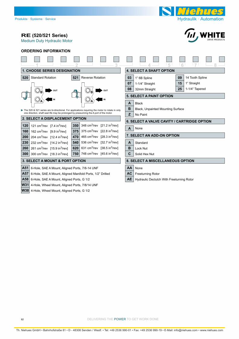
Medium Duty Hydraulic MotorRE (520/521 Series)
82 DELIVERING THE POWER TO GET WORK DONE
ORDERING INFORMATION
1 2 3 4 5 6 7 8
121 cm3/rev [7.4 in3/rev]
162 cm3/rev [9.9 in3/rev]
204 cm3/rev [12.4 in3/rev]
232 cm3/rev [14.2 in3/rev]
261 cm3/rev [15.9 in3/rev]
300 cm3/rev [18.3 in3/rev]
Standard Rotation Reverse Rotation
The 520 & 521 series are bi-directional. For applications requiring the motor to rotate in only one direction, shaft seal life may be prolonged by pressurizing the A port of the motor.
348 cm3/rev [21.2 in3/rev]
375 cm3/rev [22.8 in3/rev]
465 cm3/rev [28.3 in3/rev]
536 cm3/rev [32.7 in3/rev]
631 cm3/rev [38.5 in3/rev]
748 cm3/rev [45.6 in3/rev]
6-Hole, SAE A Mount, Aligned Ports, 7/8-14 UNF
6-Hole, SAE A Mount, Aligned Manifold Ports, 1/2” Drilled
6-Hole, SAE A Mount, Aligned Ports, G 1/2
4-Hole, Wheel Mount, Aligned Ports, 7/8/14 UNF
4-Hole, Wheel Mount, Aligned Ports, G 1/2
1” 6B Spline
1-1/4” Straight
32mm Straight
Black
Black, Unpainted Mounting Surface
No Paint
Standard
Lock Nut
Solid Hex Nut
None
Freeturning Rotor
Hydraulic Declutch With Freeturning Rotor
None
14 Tooth Spline
1” Straight
1-1/4” Tapered
520
1. CHOOSE SERIES DESIGNATION
2. SELECT A DISPLACEMENT OPTION
120160200230260300
350375470540620750
3. SELECT A MOUNT & PORT OPTION
A51A57A58W31W38
4. SELECT A SHAFT OPTION
030708
091525
5. SELECT A PAINT OPTION
ABZ
6. SELECT A VALVE CAVITY / CARTRIDGE OPTION
7. SELECT AN ADD-ON OPTION
ABC
8. SELECT A MISCELLANEOUS OPTION
AAACAE
521
A
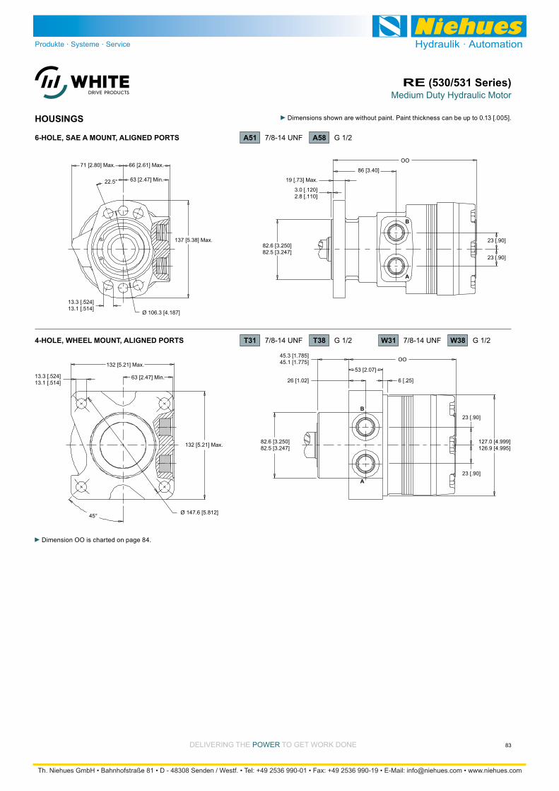
Medium Duty Hydraulic MotorRE (530/531 Series)
83DELIVERING THE POWER TO GET WORK DONE
HOUSINGS
Dimension OO is charted on page 84.
13.3 [.524]13.1 [.514]
82.6 [3.250]82.5 [3.247]
19 [.73] Max.
3.0 [.120]2.8 [.110]
137 [5.38] Max.
Ø 106.3 [4.187]
22.5° 63 [2.47] Min.
71 [2.80] Max. 66 [2.61] Max.
23 [.90]
23 [.90]
86 [3.40]
A
B
OO
13.3 [.524]13.1 [.514]
82.6 [3.250]82.5 [3.247]
23 [.90]
127.0 [4.999]126.9 [4.995]
45.3 [1.785]45.1 [1.775]
132 [5.21] Max.
Ø 147.6 [5.812]45°
63 [2.47] Min.
132 [5.21] Max.
23 [.90]
6 [.25]
53 [2.07]
A
B
OO
26 [1.02]
A58 G 1/26-HOLE, SAE A MOUNT, ALIGNED PORTS A51 7/8-14 UNF
4-HOLE, WHEEL MOUNT, ALIGNED PORTS T31 7/8-14 UNF T38 G 1/2 W31 7/8-14 UNF W38 G 1/2

Medium Duty Hydraulic MotorRE (530/531 Series)
84 DELIVERING THE POWER TO GET WORK DONE
TECHNICAL INFORMATION
3000
9000
SAE A MOUNTS
7000
8000
6000
5000
4000
lb
2000
1000
1000
4000
3000
3500
2500
2000
1500
daN
500
3 in4-3 21-2 0-1
75 mm1005025-75 -50 0-25
445 daN [1000 lb]
445 daN [1000 lb]
BEARING
SHAFT
The bearing curve represents allowable bearing loads based on ISO 281 bearing capacity for an L10 life of 2,000 hours at 100 rpm. Radial loads for speeds other than 100 rpm may be calculated using the multiplication factor table on page 8.
ALLOWABLE SHAFT LOAD / BEARING CURVE
3000
9000
7000
8000
6000
5000
4000
lb
2000
1000
1000
4000
3000
3500
2500
2000
1500
daN
500
5 in74 6-2 32-1 10
125 mm175100 1507550-50 -25 250
T31 & T38 WHEEL MOUNTS
445 daN [1000 lb]
445 daN [1000 lb]
BEARING
SHAFT
14000
W31 & W38 WHEEL MOUNTS
10000
12000
8000
6000
4000
lb
2000 1000
6000
4000
5000
3000
2000
daN5 in4 6-2 32-1 10
125 mm100 1507550-50 -25 250
445 daN [1000 lb]
445 daN [1000 lb]
BEARING
SHAFT
LENGTH & WEIGHT CHARTDimension OO is the overall motor length from the rear of the motor to
are referenced on detailed housing drawings listed on page 83.
All RE series motor weights can vary ± 0.5
such as housing, shaft, endcover, options etc.
SAE AMounts
Wheel Mounts WeightOO
#120160200230260300350375470540620750
kg [lb]
13.3 [29.4]
13.3 [29.4]
13.7 [30.2]
13.8 [30.4]
14.1 [31.0]
14.4 [31.8]
15.5 [34.2]
15.0 [33.0]
15.5 [34.2]
16.1 [35.4]
16.8 [36.9]
17.5 [38.5]
mm [in]
187 [7.37]
187 [7.37]
191 [7.51]
193 [7.61]
196 [7.70]
199 [7.83]
213 [8.38]
205 [8.08]
213 [8.38]
219 [8.62]
227 [8.95]
237 [9.33]
mm [in]
156 [6.15]
156 [6.15]
159 [6.29]
162 [6.38]
165 [6.48]
168 [6.61]
182 [7.16]
174 [6.86]
182 [7.16]
188 [7.40]
196 [7.77]
206 [8.11]

Medium Duty Hydraulic MotorRE (530/531 Series)
85DELIVERING THE POWER TO GET WORK DONE
35.0 [1.379]35.0 [1.378]
PP
PP
58 [2.28]
M8x1.25, Min. Depth 18 [.69]
38.0 [1.391]38.0 [1.389]
45.5 [1.791]45.0 [1.772]6 [.24]
10.0 [.394]10.0 [.392]
38.1 [1.499]38.0 [1.498]
PP
80 [3.07]
3/8-16 UNC,Min. Depth 19 [.75]
42.4 [1.671]42.1 [1.657]
38.9 [1.530]37.6 [1.480]10[.39]
9.6 [.376]9.5 [.375]
4 [.15]
8.0 [.314]8.0 [.313]
22.9 [.900]22.6 [.890]
36 [1.42]22 [.87]
Ø5 [.20]
3 [.12]
35.0 [1.378]34.5 [1.358]
1:10 Taper
PP
4 [.15]
8.0 [.314]8.0 [.313]
44 [1.72]19 [.75]
Ø4 [.17]
5 [.20]
38.1 [1.500]38.1 [1.499]
1:8 Taper
40 [1.58]Wire Ring
31.8 [1.250]30.5 [1.200]
PP
4 [.15]
8.0 [.314]8.0 [.313]
41 [1.63]21 [.83]
Ø4 [.17]
5 [.20]
35.1 [1.380]34.9 [1.375]
1:8 Taper
31.8 [1.250]30.5 [1.200]
27 35mm Straight
Max. Torque: 1200 Nm [10600 lb-in]
31 1-1/2” Tapered28 35mm” Tapered
30 1-1/2” Straight
Max. Torque: 1200 Nm [10600 lb-in] Max. Torque: 1200 Nm [10600 lb-in]
Max. Torque: 1200 Nm [10600 lb-in]
A slotted hex nut is standard on this shaft.
A slotted hex nut is standard on this shaft.
M4 1-3/8” Tapered
Max. Torque: 1200 Nm [10600 lb-in]
A slotted hex nut is standard on this shaft.
SHAFTS
MOUNTING / SHAFT LENGTH CHART
Dimension PP is the overall dis-tance from the motor mounting surface to the end of the shaft and is referenced on detailed shaft draw-ings above.
Shaft lengths vary ± 0.8 mm [.030 in.]
#27283031M4
mm [in]
104 [3.97]
105 [4.14]
118 [4.63]
115 [4.53]
114 [4.49]
mm [in]
N/A
N/A
87 [3.42]
84 [3.32]
83 [3.28]
PP SAE AMounts
Wheel Mounts
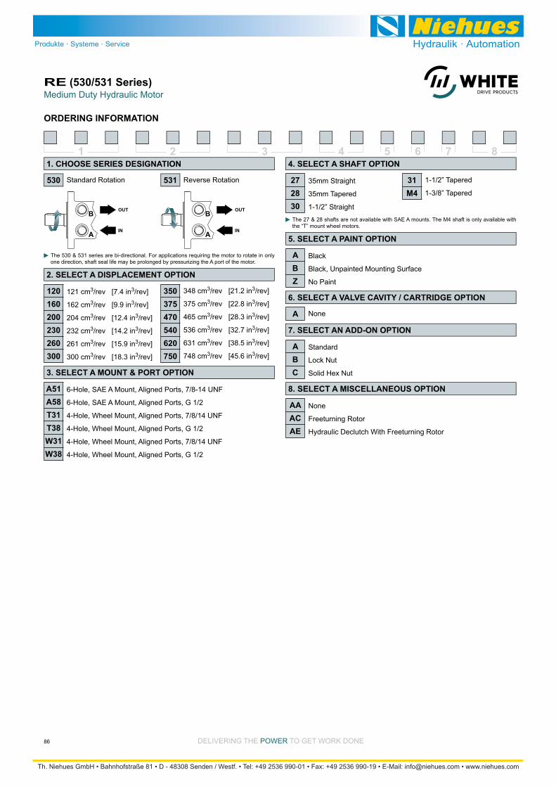
Medium Duty Hydraulic MotorRE (530/531 Series)
86 DELIVERING THE POWER TO GET WORK DONE
ORDERING INFORMATION
1 2 3 4 5 6 7 8
121 cm3/rev [7.4 in3/rev]
162 cm3/rev [9.9 in3/rev]
204 cm3/rev [12.4 in3/rev]
232 cm3/rev [14.2 in3/rev]
261 cm3/rev [15.9 in3/rev]
300 cm3/rev [18.3 in3/rev]
Standard Rotation Reverse Rotation
The 530 & 531 series are bi-directional. For applications requiring the motor to rotate in only one direction, shaft seal life may be prolonged by pressurizing the A port of the motor.
6-Hole, SAE A Mount, Aligned Ports, 7/8-14 UNF
6-Hole, SAE A Mount, Aligned Ports, G 1/2
4-Hole, Wheel Mount, Aligned Ports, 7/8/14 UNF
4-Hole, Wheel Mount, Aligned Ports, G 1/2
4-Hole, Wheel Mount, Aligned Ports, 7/8/14 UNF
4-Hole, Wheel Mount, Aligned Ports, G 1/2
35mm Straight
35mm Tapered
1-1/2” Straight
Black
Black, Unpainted Mounting Surface
No Paint
Standard
Lock Nut
Solid Hex Nut
None
Freeturning Rotor
Hydraulic Declutch With Freeturning Rotor
None
1-1/2” Tapered
1-3/8” Tapered
The 27 & 28 shafts are not available with SAE A mounts. The M4 shaft is only available with the “T” mount wheel motors.
530
1. CHOOSE SERIES DESIGNATION
2. SELECT A DISPLACEMENT OPTION
120160200230260300
3. SELECT A MOUNT & PORT OPTION
A51A58T31T38W31W38
4. SELECT A SHAFT OPTION
272830
31M4
5. SELECT A PAINT OPTION
ABZ
6. SELECT A VALVE CAVITY / CARTRIDGE OPTION
7. SELECT AN ADD-ON OPTION
ABC
8. SELECT A MISCELLANEOUS OPTION
AAACAE
531
A
348 cm3/rev [21.2 in3/rev]
375 cm3/rev [22.8 in3/rev]
465 cm3/rev [28.3 in3/rev]
536 cm3/rev [32.7 in3/rev]
631 cm3/rev [38.5 in3/rev]
748 cm3/rev [45.6 in3/rev]
350375470540620750

Medium Duty Hydraulic MotorRE (535/536 Series)
87DELIVERING THE POWER TO GET WORK DONE
HOUSINGS
82.54 [3.249]82.46 [3.247]
23 [.90]127.0 [4.999]126.8 [4.994]
46.3 [1.824]46.1 [1.815]
23 [.90]
8.3 [.325]8.0 [.316]
38 [1.48]
A
B
19 [.74]
131 [5.16]
131 [5.16]
63 [2.47] Min.
45° Ø 147.6 [5.812]
13.3 [.523]13.1 [.514]
4-HOLE, WHEEL MOUNT, ALIGNED PORTS T31 7/8-14 UNF
TECHNICAL INFORMATION
The bearing curve represents allowable bearing loads based on ISO 281 bearing capacity for an L10 life of 2,000 hours at 100 rpm. Radial loads for speeds other than 100 rpm may be calculated using the multiplication factor table on page 8.
ALLOWABLE SHAFT LOAD / BEARING CURVE
3000
9000
WHEEL MOUNT
7000
8000
6000
5000
4000
lb
2000
1000
1000
4000
3000
3500
2500
2000
1500
daN
500
6 in7-2 53-1 1 420
150 mm17512575-50 -25 25 100500
445 daN [1000 lb]
445 daN [1000 lb]
BEARING
SHAFT
LENGTH & WEIGHT CHARTDimension QQ is the overall motor length from the rear of the motor to
are referenced on detailed housing drawings listed above.
All RE series motor weights can vary ± 0.5
such as housing, shaft, endcover, options etc.
#200230300375
kg [lb]
13.7 [30.1]
13.8 [30.4]
14.4 [31.7]
15.0 [33.0]
mm [in]
129 [5.08]
132 [5.18]
137 [5.40]
144 [5.65]
QQ Length Weight
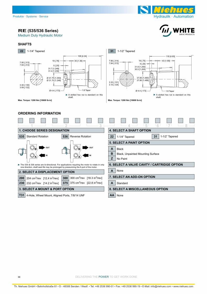
Medium Duty Hydraulic MotorRE (535/536 Series)
88 DELIVERING THE POWER TO GET WORK DONE
SHAFTS
108 [4.24]
37.85 [1.490]37.80 [1.488]
118 [4.65]
43 [1.69]
3.33 [.131]3.15 [.124]
31.8 [1.250]30.5 [1.200]
19 [.75]5 [.20]
7.96 [.314]7.94 [.313]
3.30 [.130]3.09 [.122]
7.95 [.313]7.93 [.312]
31.7 [1.248]31.4 [1.236]
35 [1.36]19 [.76]
Ø 4.4 [.173]
5 [.20]
1:8 Taper
Ø 31.75 [1.250]Ø 31.70 [1.248]
Ø 4.4 [.173] 1:8 Taper
22 1-1/4” Tapered
Max. Torque: 1200 Nm [10600 lb-in]
31 1-1/2” Tapered
Max. Torque: 1200 Nm [10600 lb-in]
A slotted hex nut is standard on this shaft.
A slotted hex nut is standard on this shaft.
ORDERING INFORMATION
1 2 3 4 5 6 7 8
204 cm3/rev [12.4 in3/rev]
232 cm3/rev [14.2 in3/rev]
Standard Rotation Reverse Rotation
The 535 & 536 series are bi-directional. For applications requiring the motor to rotate in only one direction, shaft seal life may be prolonged by pressurizing the A port of the motor.
4-Hole, Wheel Mount, Aligned Ports, 7/8/14 UNF
1-1/4” Tapered
Black
Black, Unpainted Mounting Surface
No Paint
Standard
None
None
1-1/2” Tapered535
1. CHOOSE SERIES DESIGNATION
2. SELECT A DISPLACEMENT OPTION
200230
3. SELECT A MOUNT & PORT OPTION
T31
4. SELECT A SHAFT OPTION
22 31
5. SELECT A PAINT OPTION
ABZ
6. SELECT A VALVE CAVITY / CARTRIDGE OPTION
7. SELECT AN ADD-ON OPTION
A
8. SELECT A MISCELLANEOUS OPTION
AA
536
A
300 cm3/rev [18.3 in3/rev]
375 cm3/rev [22.8 in3/rev]
300375
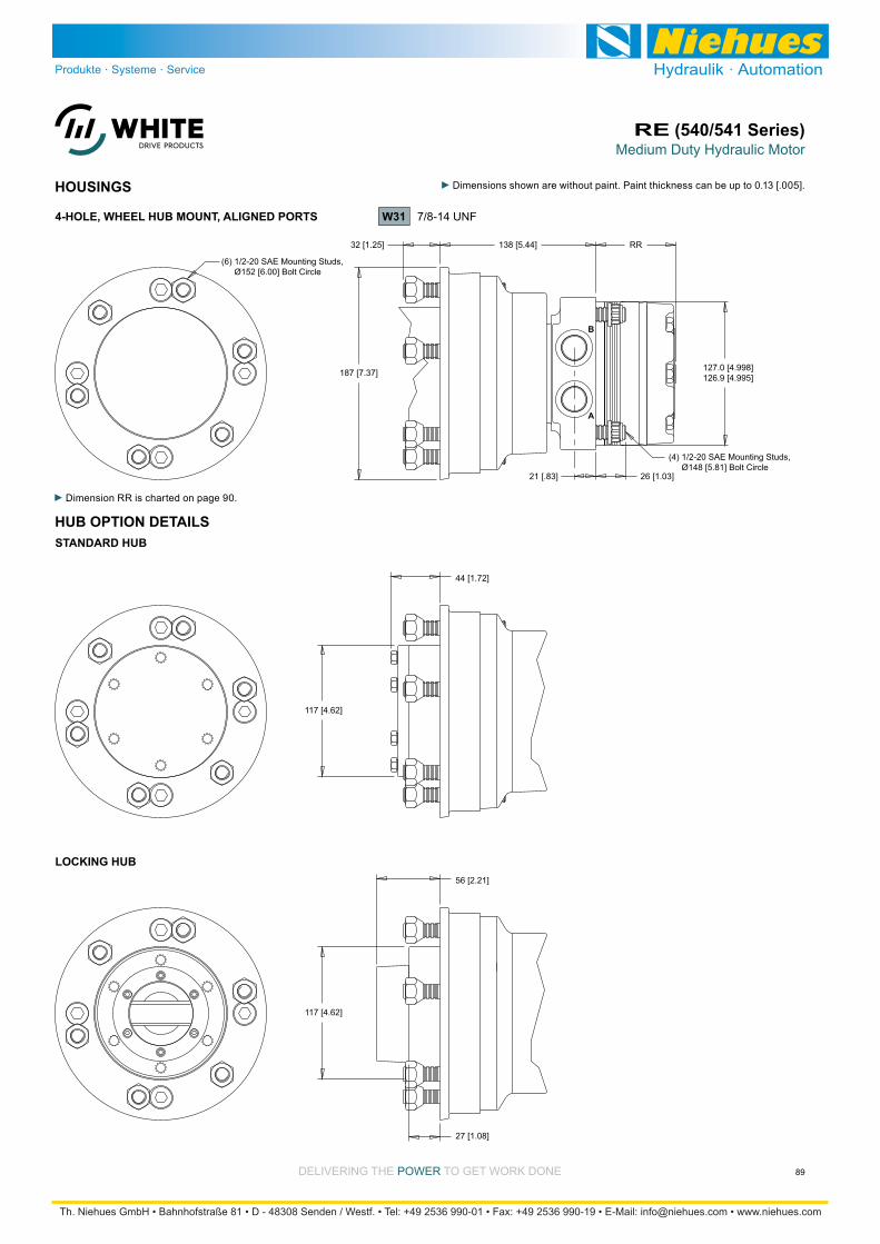
Medium Duty Hydraulic MotorRE (540/541 Series)
89DELIVERING THE POWER TO GET WORK DONE
HOUSINGS
127.0 [4.998]126.9 [4.995]
(6) 1/2-20 SAE Mounting Studs, Ø152 [6.00] Bolt Circle
(4) 1/2-20 SAE Mounting Studs, Ø148 [5.81] Bolt Circle
138 [5.44]
A
B
RR32 [1.25]
187 [7.37]
21 [.83] 26 [1.03]
4-HOLE, WHEEL HUB MOUNT, ALIGNED PORTS W31 7/8-14 UNF
Dimension RR is charted on page 90.
HUB OPTION DETAILS
44 [1.72]
117 [4.62]
117 [4.62]
56 [2.21]
27 [1.08]
STANDARD HUB
LOCKING HUB
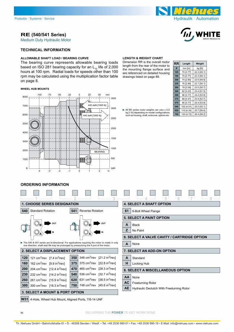
Medium Duty Hydraulic MotorRE (540/541 Series)
90 DELIVERING THE POWER TO GET WORK DONE
3000
8000
WHEEL HUB MOUNTS
7000
6000
5000
4000
lb
2000
1000
1000
3500
3000
2500
2000
1500
daN
500
2 in-4 10-3 -1-2
50 mm-100 250-75 -25-50
445 daN [1000 lb]
445 daN [1000 lb]
BEARING
The bearing curve represents allowable bearing loads based on ISO 281 bearing capacity for an L10 life of 2,000 hours at 100 rpm. Radial loads for speeds other than 100 rpm may be calculated using the multiplication factor table on page 8.
ALLOWABLE SHAFT LOAD / BEARING CURVE LENGTH & WEIGHT CHARTDimension RR is the overall motor length from the rear of the motor to
are referenced on detailed housing drawings listed on page 89.
All RE series motor weights can vary ± 0.5
such as housing, shaft, endcover, options etc.
TECHNICAL INFORMATION
1 2 3 4 5 6 7 8
121 cm3/rev [7.4 in3/rev]
162 cm3/rev [9.9 in3/rev]
204 cm3/rev [12.4 in3/rev]
232 cm3/rev [14.2 in3/rev]
261 cm3/rev [15.9 in3/rev]
300 cm3/rev [18.3 in3/rev]
Standard Rotation Reverse Rotation
The 540 & 541 series are bi-directional. For applications requiring the motor to rotate in only one direction, shaft seal life may be prolonged by pressurizing the A port of the motor.
4-Hole, Wheel Hub Mount, Aligned Ports, 7/8-14 UNF
6-Bolt Wheel Flange
Black
No Paint
Standard
Locking Hub
None
Freeturning Rotor
Hydraulic Declutch With Freeturning Rotor
None
540
1. CHOOSE SERIES DESIGNATION
2. SELECT A DISPLACEMENT OPTION
120160200230260300
3. SELECT A MOUNT & PORT OPTION
W31
4. SELECT A SHAFT OPTION
61
5. SELECT A PAINT OPTION
AZ
6. SELECT A VALVE CAVITY / CARTRIDGE OPTION
7. SELECT AN ADD-ON OPTION
AH
8. SELECT A MISCELLANEOUS OPTION
AAACAE
541
A
348 cm3/rev [21.2 in3/rev]
375 cm3/rev [22.8 in3/rev]
465 cm3/rev [28.3 in3/rev]
536 cm3/rev [32.7 in3/rev]
631 cm3/rev [38.5 in3/rev]
748 cm3/rev [45.6 in3/rev]
350375470540620750
ORDERING INFORMATION
Length Weight
#120160200230260300350375470540620750
kg [lb]
22.3 [49.1]
22.3 [49.1]
22.6 [49.9]
22.7 [50.1]
23.0 [50.7]
23.4 [51.5]
24.4 [53.9]
23.9 [52.7]
24.4 [53.9]
25.0 [55.1]
25.7 [56.6]
26.4 [58.2]
mm [in]
70 [2.77]
70 [2.77]
74 [2.90]
76 [2.99]
79 [3.09]
82 [3.22]
96 [3.77]
88 [3.47]
96 [3.77]
102 [4.01]
110 [4.34]
120 [4.72]
RR

This catalog provides product options for further investigation by customers having technical expertise with respect to the use of such products. It is solely the responsibility of the customer to thoroughly analyze all aspects of the customer’s application and to review the information concerning the product in the current product catalog. Due to the diversity of
assure that all performance, safety and warning requirements of the application are met. The customer is further solely responsible for all testing to verify acceptable life and performance of White Drive Products, Inc.’s products under actual operating conditions.
White Drive Products, Inc. has made all reasonable efforts to present accurate information in this catalog and shall not be responsible for any incorrect information which may result from unintentional errors or oversight. Due to continuous
Inc. at any time without notice. The customer should consult a sales representative of White Drive Products, Inc. for detailed information and to determine any changes in the information in this catalog.
IMPROPER SELECTION OR IMPROPER USE OF THE PRODUCTS DESCRIBED HEREIN CAN RESULT IN DEATH, PERSONAL INJURY AND/OR PROPERTY DAMAGE. WHITE DRIVE PRODUCTS, INC.’S SOLE RESPONSIBILITY WITH RESPECT TO ITS PRODUCTS IS SET FORTH IN WHITE DRIVE PRODUCTS, INC.’S WARRANTY/LIMITATION OF LIABILITY POLICY STATED HEREIN. EXCEPT AS SPECIFICALLY PROVIDED IN WHITE DRIVE PRODUCTS, INC.’S WARRANTY/LIMITATION OF LIABILITY POLICY, WHITE DRIVE PRODUCTS, INC. DISCLAIMS AND SHALL NOT BE LIABLE FOR ANY DAMAGES (INCLUDING DEATH), LIABILITY, CLAIMS, ACTIONS, CAUSES OF ACTION OR COST OF ANY KIND OR CHARACTER ARISING OUT OF OR RELATING IN ANY WAY TO ITS PRODUCTS, OR ANY USE, SELECTION OR APPLICATION OF ITS PRODUCTS. OUR WARRANTY/LIMITATION OF LIABILITY POLICY IS SUBJECT TO PERIODIC CHANGE; FOR A COPY OF OUR CURRENT WARRANTY/LIMITATION OF LIABILITY POLICY, PLEASE CONSULT A SELECT REPRESENTATIVE OF WHITE DRIVE PRODUCTS, INC.
DISCLAIMER
PATENTED MOTOR DESIGN
at the heart of every White Drive Products motor, this revolutionary rotor design is what sets White Drive Products mo-tors apart from all other gerotor style hydraulic motors. Although other rotors may appear similar to the Roller Stator® design, closer examination reveals critical differences. The most important difference between White Drive Products
points on the rotor to maintain contact with the sealing rollers to isolate the high and low pressure areas of the motor from each other. Full contact by the remaining four rollers is functionally unnecessary, and robs power from the motor by
contact pressure of the rotor on the four rollers in noncritical positions was reduced, bringing about some very positive
of the motor over the entire operating range, producing more usable power at the output shaft. Equally important, allowing
UNITED STATESWHITE DRIVE PRODUCTS, INC 110 Bill Bryan Blvd P.O. Box 2700, Hopkinsville, KY 42241, USAPhone: +1.270.885.1110Fax: +1.270.886.8462 [email protected]
GERMANYWHITE DRIVE PRODUCTS GMBH Mannsnetterstrasse 34, 88145 Opfenbach, GermanyPhone: +49.8385.924988.0Fax: +49.8385.924988.9 [email protected]
CHINAWHITE (CHINA) DRIVE PRODUCTS CO., LTD. 1–8 Ning Zhen Gong Lu, Zhenjiang, 212021, Jiangsu, ChinaPhone: +86.511.8572.9988Fax: +86.511.8572.8950 [email protected]
whitedriveproducts.comPC990501 - 011017


![Hydraulic Power Units - Poclain Hydraulics · HPD Model AC Motor kW [HP] Closed loop pump cm3/rev [cu.in/rev] Preferred Hydraulic motor Single hydraulic motor drive S.1 132 [177]](https://static.fdocuments.in/doc/165x107/60dce74a6f5c4a6e147d4e1a/hydraulic-power-units-poclain-hydraulics-hpd-model-ac-motor-kw-hp-closed-loop.jpg)