HYDRAULIC MOTORS MP - Hydraulics...
16
HYDRAULIC MOTORS MP Pressure Losses 12 APPLICATION » » » » » » » Conveyors Feeding mechanism of robots and manipulators Metal working machines Textile machines Machines for agriculture Food industries etc. Grass cutting machinery Specification data ...............13÷14 Function diagrams ..............15÷21 Dimensions and mounting ........ 22 Wheel motor ............................ 23 Shaft extensions ........................ 24 Order code .............................. 27 Permissible shaft loads .............. 25 Permissible shaft Seal Pressure ... 26 CONTENTS OPTIONS 30 25 20 15 10 5 0 0 10 20 30 40 50 60 70 80 Q l/min p bar 25÷623,6 95÷1600 3,3÷50 3,3÷10,5 55÷140 40÷60 10 Mineral based- HLP(DIN 51524) or HM(ISO 6743/4) -30÷90 20÷75 ISO code 20/16 (Min. recommended fluid filtration of 25 micron) GENERAL 100 140 Pressure drop (bar) Viscosity (mm /s) 2 Oil flow in drain line (l/min) 20 35 20 35 2,5 1,8 3,5 2,8 Oil flow in drain line » » » » » » » » » Model- Spool valve, gerotor Flange and wheel mount Motor with needle bearing Side and rear ports Shafts- straight, splined and tapered Shaft seal for high and low pressure Metric and BSPP ports Speed sensoring Other special features Displacement, Max. Speed, Max. Torque, Max. Output, Max. Pressure Drop, Max. Oil Flow, Min. Speed, Pressure fluid Temperature range, Optimal Viscosity range, Filtration [cm /rev.] [RPM] [daNm] [kW] [bar] [l/min] [RPM] [ C] [mm /s] 3 O 2
Transcript of HYDRAULIC MOTORS MP - Hydraulics...

HYDRAULIC MOTORS MP
Pressure Losses
12
APPLICATION
»
»
»
»
»
»
»
Conveyors
Feeding mechanism of robots and manipulators
Metal working machines
Textile machines
Machines for agriculture
Food industries
etc.Grass cutting machinery
Specification data ...............13÷14
Function diagrams ..............15÷21
Dimensions and mounting ........ 22
Wheel motor ............................ 23
Shaft extensions ........................ 24
Order code .............................. 27
Permissible shaft loads .............. 25
Permissible shaft Seal Pressure ... 26
CONTENTS OPTIONS
30
25
20
15
10
5
0
0 10 20 30 40 50 60 70 80 Q l/min
pbar
25÷623,6
95÷1600
3,3÷50
3,3÷10,5
55÷140
40÷60
10
Mineral based- HLP(DIN 51524) or HM(ISO 6743/4)
-30÷90
20÷75
ISO code 20/16 (Min. recommended fluid filtration of 25 micron)
GENERAL
100
140
Pressure drop(bar)
Viscosity(mm /s)
2
Oil flow indrain line
(l/min)
20
35
20
35
2,5
1,8
3,5
2,8
Oil flow in drain line
»
»
»
»
»
»
»
»
»
Model- Spool valve, gerotor
Flange and wheel mount
Motor with needle bearing
Side and rear ports
Shafts- straight, splined and tapered
Shaft seal for high and low pressure
Metric and BSPP ports
Speed sensoring
Other special features
Displacement,
Max. Speed,
Max. Torque,
Max. Output,
Max. Pressure Drop,
Max. Oil Flow,
Min. Speed,
Pressure fluid
Temperature range,
Optimal Viscosity range,
Filtration
[cm /rev.]
[RPM]
[daNm]
[kW]
[bar]
[l/min]
[RPM]
[ C]
[mm /s]
3
O
2

13
Type25
Displacement, [cm /rev.]
Max. Speed,
[RPM]
Max.
Torque
[daNm]
Max. Output,
[kW]
Max. Pressure
Drop
[bar]
Max. Oil Flow
[l/min]
Max. Inlet
Pressure
[bar]
Max. Return Pressure
with Drain Line
[bar]
Max. Starting Pressure
with Unloaded Shaft, [bar]
Min. Starting Torque
[daNm]
Min. Speed***, [RPM]
Weight, avg. [kg]
3
cont.
int.*
cont.
int.*
peak**
cont.
int.*
cont.
int.*
peak**
cont.
int.*
cont.
int.*
peak**
cont.
int.*
peak**
MP(F)
MPQ(N)
MP(F)(N)E
MPW(N)
MPQ(N)E
MOTORS
MP
* Intermittent operation: the permissible values may occur for max. 10% of every minute.** Peak load: the permissible values may occur for max. 1% of every minute.*** For speeds of 10 RPM or lower, consult factory or your regional manager.1. Intermittent speed and intermittent pressure drop must not occur simultaneously.2. Recommended filtration is per ISO cleanliness code 20/16. A nominal filtration of 25 micron or better.3. Recommended using a premium quality, anti-wear type mineral based hydraulic oil
4. Recommended minimum oil viscosity 13 mm²/s at operating temperatures.5. Recommended maximum system operating temperature is 82 C.6. To assure optimum motor life fill with fluid prior to loading and run at moderate load and speed for 10-15 minutes.
HLP(DIN51524) or HM (ISO 6743/4).If using synthetic fluids consult the factory for alternative seal materials.
0
at max. press.drop cont.at max. press.drop int.*
MP
32 40 50 80 100 125 160 200 250 315 400 500 630
Specification Data for MP... motors with C, CO, SH, K and SA shafts.
25
1600
1800
3,3
4,7
6,7
4,5
6,1
100
140
225
40
45
175
200
225
175
200
225
10
3
4,2
20
5,6
5,0
6,1
5,3
5,5
32
1560
1720
4,3
6,1
8,6
5,8
7,8
100
140
225
50
55
175
200
225
175
200
225
10
4
5,6
15
5,6
5,0
6,1
5,3
5,5
40
1500
1750
6,2
8,2
10,7
8,4
11,6
120
155
225
60
70
175
200
225
175
200
225
10
5,4
6,9
10
5,7
5,1
6,2
5,4
5,6
49,5
1210
1515
9,4
11,9
14,3
10,1
12,2
140
175
225
60
70
175
200
225
175
200
225
10
7,8
10
10
5,8
5,2
6,3
5,5
5,7
79,2
755
945
15,1
19,5
22,4
10,2
12,5
140
175
225
60
70
175
200
225
175
200
225
10
13,2
16,8
10
5,9
5,3
6,4
5,6
5,8
99
605
755
19,3
23,7
27,5
10,5
12,8
140
175
225
60
70
175
200
225
175
200
225
10
16,6
21
10
6,1
5,5
6,6
5,8
6,0
123,8
486
605
23,7
29,8
36,5
10
12
140
175
225
60
70
175
200
225
175
200
225
9
20,7
26,6
10
6,2
5,6
6,7
5,9
6,1
158,4
378
472
31,3
37,8
43,8
10,1
12,1
140
175
225
60
70
175
200
225
175
200
225
8
28,2
35,5
10
6,4
5,8
6,9
6,1
6,3
198
303
378
36,6
45,6
55
10
12
140
175
225
60
70
175
200
225
175
200
225
7
33,5
42,6
10
6,6
6,0
7,1
6,3
6,5
247,5
242
303
38
58,3
68,5
7,5
12
110
175
225
60
70
175
200
225
175
200
225
6
33,6
54,2
10
6,8
6,2
7,3
6,5
6,7
316,8
190
236
38
56
85
5,7
9
90
140
225
60
70
175
200
225
175
200
225
5
34,4
61,9
10
7,1
6,5
7,6
6,8
7,0
396
150
189
36
59
85,4
4,6
7,8
70
115
180
60
70
175
200
225
175
200
225
5
34,5
60,8
10
7,6
6,8
8,1
7,2
7,3
495
120
150
39
57
78
3,5
7,2
60
90
130
60
70
140
175
225
140
175
225
5
36
54
10
8,9
8,3
9,3
8,6
8,8
623,6
95
120
44
64
82
3,3
5,6
55
80
110
60
70
140
175
225
140
175
225
5
41,5
62
10
9,5
9,0
10
9,2
8,5
(ø28,56 sealing diameter)
SPECIFICATION DATA

14
SPECIFICATION DATA (continued)
MOTORS
MP
* Intermittent operation: the permissible values may occur for max. 10% of every minute.** Peak load: the permissible values may occur for max. 1% of every minute.*** For speeds of 10 RPM or lower, consult factory or your regional manager.1. Intermittent speed and intermittent pressure drop must not occur simultaneously.2. Recommended filtration is per ISO cleanliness code 20/16. A nominal filtration of 25 micron or better.3. Recommended using a premium quality, anti-wear type mineral based hydraulic oil
4. Recommended minimum oil viscosity 13 mm²/s at operating temperatures.5. Recommended maximum system operating temperature is 82 C.6. To assure optimum motor life fill with fluid prior to loading and run at moderate load and speed for 10-15 minutes.
HLP(DIN51524) or HM (ISO 6743/4).If using synthetic fluids consult the factory for alternative seal materials.
0
Type25
Displacement, [cm /rev.]
Max. Speed,
[RPM]
Max.
Torque
[daNm]
Max. Output,
[kW]
Max. Pressure
Drop
[bar]
Max. Oil Flow
[l/min]
Max. Inlet
Pressure
[bar]
Max. Return Pressure
with Drain Line
[bar]
Max. Starting Pressure
with Unloaded Shaft, [bar]
Min. Starting Torque
[daNm]
Min. Speed***, [RPM]
Weight, avg. [kg]
3
cont.
int.*
cont.
int.*
peak**
cont.
int.*
cont.
int.*
peak**
cont.
int.*
cont.
int.*
peak**
cont.
int.*
peak**
MP(F)...
MP(F)E...B
B
at max. press.drop cont.at max. press.drop int.*
MP
32 40 50 80 100 125 160 200 250 315 400 500 630
Specification Data for MP... motors with CB, KB, OB and HB shafts.
25
1600
1800
3,3
4,7
6,7
4,5
6,1
100
140
225
40
45
175
200
225
175
200
225
10
3
4,2
20
5,6
6,1
32
1560
1720
4,3
6,1
8,6
5,8
7,8
100
140
225
50
55
175
200
225
175
200
225
10
4
5,6
15
5,6
6,1
40
1500
1750
6,2
8,2
10,7
8,4
11,6
120
155
225
60
70
175
200
225
175
200
225
10
5,4
6,9
10
5,7
6,2
49,5
1210
1515
9,4
11,9
14,3
10,1
12,2
140
175
225
60
70
175
200
225
175
200
225
10
7,8
10
10
5,9
6,4
79,2
755
945
15,1
19,5
22,4
10,2
12,5
140
175
225
60
70
175
200
225
175
200
225
10
13,2
16,8
10
6
6,5
99
605
755
19,3
23,7
27,5
10,5
12,8
140
175
225
60
70
175
200
225
175
200
225
10
16,6
21
10
6,2
6,7
123,8
486
605
23,7
29,8
36,5
10
12
140
175
225
60
70
175
200
225
175
200
225
9
20,7
26,6
10
6,3
6,8
158,4
378
472
31,3
37,8
43,8
10,1
12,1
140
175
225
60
70
175
200
225
175
200
225
8
28,2
35,5
10
6,5
6,9
198
303
378
36,6
45,6
55
9,5
12,5
140
175
225
60
70
175
200
225
175
200
225
7
33,5
42,6
10
6,7
7,2
247,5
242
303
47
58,3
68,5
9,5
12
140
175
225
60
70
175
200
225
175
200
225
6
42,8
54,2
10
6,9
7,4
316,8
190
236
48,6
56
85
7,6
9
120
140
225
60
70
175
200
225
175
200
225
5
45,8
61,9
10
7,2
7,7
396
150
189
50
59
85,4
6,2
7,8
95
115
180
60
70
175
200
225
175
200
225
5
46,8
60,8
10
7,7
8,2
495
120
150
39
57
78
3,5
7,2
60
90
130
60
70
140
175
225
140
175
225
5
36
54
10
9
9,4
623,6
95
120
44
64
82
3,3
5,6
55
80
110
60
70
140
175
225
140
175
225
5
41,5
62
10
9,6
10,1
(ø35 sealing diameter)

MOTORS
MP
MP 32
MP 25
15
FUNCTION DIAGRAMS
The function diagrams data was collected at back pressure 5÷10 barand oil with viscosity of 32 mm²/s at 50° C.

MOTORS
MP
MP 50
MP 40
16
FUNCTION DIAGRAMS
The function diagrams data was collected at back pressure 5÷10 barand oil with viscosity of 32 mm²/s at 50° C.

MOTORS
MP
MP 100
17
FUNCTION DIAGRAMS
The function diagrams data was collected at back pressure 5÷10 barand oil with viscosity of 32 mm²/s at 50° C.
MP 80
MOTORS
MP
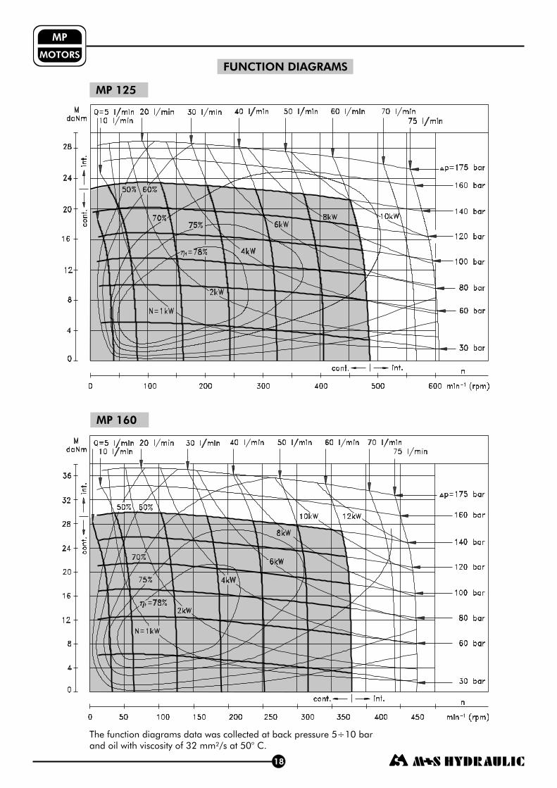
MP 160
18
FUNCTION DIAGRAMS
The function diagrams data was collected at back pressure 5÷10 barand oil with viscosity of 32 mm²/s at 50° C.
MP 125

MOTORS
MP
MP 250
19
FUNCTION DIAGRAMS
The function diagrams data was collected at back pressure 5÷10 barand oil with viscosity of 32 mm²/s at 50° C.
MP 200

Motoren
MPM
MP 400
FUNCTION DIAGRAM
The function diagram data was collected at back pressure 5÷10 barand oil with viscosity of 32 mm²/s at 50° C.
MP 315
MOTORS
MP
20

MP 630
21
FUNCTION DIAGRAM
The function diagram data was collected at back pressure 5÷10 barand oil with viscosity of 32 mm²/s at 50° C.
MP 500
MOTORS
MP
100 20 30 5040 60 70 9080 100 110 130120 140 150
n
min (rpm)-1
0
5
10
15
20
25
30
35
40
45
50
55
60
65
70
75
M
daNm
int.
cont.
int.cont.
10 l/min
Q=5 l/min 20 l/min 30 l/min 40 l/min 50 l/min 60 l/min 70 l/min 75 l/min
N=0,5kW80%
75%1kW
2kW
3kW
4kW 5kW
6kW
70%
60%
65% 50%
110 bar
90 bar
75 bar
60 bar
45 bar
30 bar
15 bar
0
5
10
15
20
25
30
35
40
45
50
55
60
65
70
int.
cont.
int.cont.
100 20 30 5040 60 70 9080 100 110 120
n
min (rpm)-1
M
daNm 10 l/min
Q=5 l/min 20 l/min 30 l/min 40 l/min 50 l/min 60 l/min 70 l/min 75 l/min
80 bar
70 bar
55 bar
45 bar
30 bar
15 bar
N=0,5kW80%
75%1kW
2kW
3kW 4kW5kW
70%65%
60%50%

22
DIMENSIONS AND MOUNTING DATA
MountingPorting
E - Rear Ports
Oval Mount (2 Holes)
F - Oval Mount (4 Holes)
Q - Square Mount (4 Bolts)C :
P :
T :
4xM8 - 13 mm depth
2xG1/2 or 2xM22x1,5 - 15 mm depth
G1/4 or M14x1,5 - 12 mm depth (plugged)(A, B)
Side Ports
L, mm L, mm L, mm L, mm L , mm1
133,2
134,5
135,2
135,6
139,6
142,2
145,6
150,2
155,6
162,2
171,6
182,2
193,0
210,5
139,4
140,7
141,4
141,8
145,8
148,4
151,8
156,4
161,8
168,4
177,8
188,4
199,0
216,5
151,2
152,5
153,2
155,8
159,8
162,4
165,8
170,4
175,8
182,4
191,8
202,4
213,0
230,5
157,4
158,7
159,4
162,0
166,0
168,6
172,0
176,6
182,0
188,6
198,0
208,6
219,0
236,5
5,20
6,30
7,40
6,67
10,67
13,33
16,67
21,33
26,67
33,33
42,67
53,33
66,63
84,00
Type
MP(F) 25
MP(F) 32
MP(F) 40
MP(F) 50
MP(F) 80
MP(F) 100
MP(F) 125
MP(F) 160
MP(F) 200
MP(F) 250
MP(F) 315
MP(F) 400
MP(F) 500
MP(F) 630
MP(F)E 25
MP(F)E 32
MP(F)E 40
MP(F)E 50
MP(F)E 80
MP(F)E 100
MP(F)E 125
MP(F)E 160
MP(F)E 200
MP(F)E 250
MP(F)E 315
MP(F)E 400
MP(F)E 500
MP(F)E 630
Type Type
MP
MPQ 50
MPQ 80
MPQ 100
MPQ 125
MPQ 160
MPQ 200
MPQ 250
MPQ 315
MPQ 400
MPQ 500
MPQ 630
Q 25
MPQ 32
MPQ 40
Type
MP
MPQE 50
MPQE 80
MPQE 100
MPQE 125
MPQE 160
MPQE 200
MPQE 250
MPQE 315
MPQE 400
MPQE 500
MPQE 630
QE 25
MPQE 32
MPQE 40
MOTORS
MP
55±0,1
55±0,1
min 15 deepmin 15 deep
max Lmax L
55±0,1Port A
Port B
Port A
Port B
106,4±0,2
ø106,4±0,2
2xø13,35+0,42xø13,35+0,4
4xø13,35+0,44xø13,35+0,4
Standard Rotation
A CWB CCW
Viewed from Shaft EndPort Pressurized -Port Pressurized -
Reverse Rotation
A CCWViewed from Shaft End
Port Pressurized -Port Pressurized -
B CW

23
DIMENSIONS AND MOUNTING DATA - MPW
P :
T :
(A, B)2xG1/2 or 2xM22x1,5 - 15 mm depth
G1/4 or M14x1,5 - 12 mm depth (plugged)
W - Wheel Mount
L, mm L , mm1
77,0
78,0
79,5
82,5
85,0
88,5
93,0
98,5
105,0
114,5
125,0
138,5
156,0
78,5
5,2
6,3
7,4
6,67
10,67
13,33
16,67
21,33
26,67
33,33
42,67
53,33
66,63
84,0
Type
MPW(N) 25
MPW(N) 32
MPW(N) 40
MP
W(N) 500
MPW(N) 630
W(N) 50
MPW(N) 80
MPW(N) 100
MPW(N) 125
MPW(N) 160
MPW(N) 200
MPW(N) 250
MPW(N) 315
MPW(N) 400
MP
MOTORS
MP
max 105max 105
ø103±0,1
55±0,1
max100
max100
maxL
maxL
min
20
T
P(A,B)P(A,B)
Port A Port B
1: Max. radial shaft load2: n=300 min3: n=500 min4: n=800 min
-1
-1
-1
PERMISSIBLE SHAFT LOADS
MPW
1: Max. radial shaft load2: n= 50 min3: n=200 min4: n=800 min
-1
-1
-1
P
daNrad
0
200
400
600
800
1000
1200
1400
1600
0 20 40 60 80 100 mm112,4
Pa =150 daNmax
Pa =200 daNmax
4
3
2
1
P
daNrad
Pa =150 daNmax
Pa =200 daNmax
00 20 40 60 80 100 112,4 mm
200
400
600
800
1000
1200
1400
1600
4
3
21
The curves apply to a B10 bearing life of 2000 hours.
MPWN
Standard Rotation
A CWB CCW
Viewed from Shaft EndPort Pressurized -Port Pressurized -
Reverse Rotation
A CCWViewed from Shaft End
Port Pressurized -Port Pressurized -
B CW

24
SHAFT EXTENSIONS FOR MP AND MR MOTORSMOTORS
MP+MR
CB ø32 straight, Parallel key A10x8x45 DIN 6885Max. Torque 77 daNm
-
SB - splined A25x22xH10 DIN 5482Max. Torque 34 daNm
KB - tapered 1:10, key B6x6x20 DIN 6885Max. Torque 77 daNm
Parallel
C ø25 straight, key A8x7x32 DIN 6885Max. Torque 34 daNm
- Parallel
CO ø1" straight, key ¼"x¼"x1¼" BS46Max. Torque 34 daNm
- Parallel
SH - splined, BS 2059 (SAE 6B)Max. Torque 40 daNm
K tapered 1:10, key B5x5x14 DIN 6885Max. Torque 40 daNm
- Parallel
SA splined, B25x22h9 DIN 5482Max. Torque 40 daNm
-
- Motor Mounting Surface
HB splined , ANSI B92.1-1976 NormMax. Torque 77 daNm
- ø1¼" 14T
OB tapered 1:8 , key "x "x1¼" BS46Max. Torque 77 daNm
- SAEJ 501 Parallel 5
16
5
16
ø25±0,210
ø22±0,130
ø25,32±0,03
min 26,4min 26,4
M8
min16 Deep
M8
min16 Deep
43,2±0,5
M8
min16 Deep
M8
min16 Deep
43,2±0,5
M8
min16 Deep
M8
min16 Deep 56,5+0,4
-1,0
+0,4
-1,0
43,2±0,5M8
min16 Deep
M8
min16 Deep
56,5+0,4
-1,0
+0,4
-1,0
35±0,6
ø4
5±0,25
S=1 / "
Tightening Torque
20±1 daNm
716
56,5+0,4
-1,0
+0,4
-1,0
M8
min16 Deep
M8
min16 Deep
58±0,4
36±0,7
ø4,5±0,1
5±0,25
ø35±0,01
S=41Tightening Torque
20±1 daNm
43,2±0,5M8
min16 Deep
M8
min16 Deep
max 49*max 49*
max 49*max 49*
max 49*max 49*
S=30Tightening Torque
10±1 daNmø4,5±0,1
5±0,25
ø28,56±0,01
max 49*max 49*
max 49*max 49*
* - For Q-flange

25
PERMISSIBLE SHAFT LOADS FOR MP AND MR MOTORS
The permissible radial shaft load P depends on the speed (RPM) and distance (L) from the point of load
to the mounting flange.rad
Radial Shaft Load P for Shaft Extensions
by L=30 (24) mmrad C, CO
MOTORS
MP+MR
Mounting Flange
Shaft Versioncylindrical - C, COtapered - K, splined - SH
cylindrical - C, COsplined - HBcylindrical - CB
Radial Shaft Load Pradx , daN800
n2500095+L
x , daN800n
1875095+L
x , daN800n
25000101+L
*
1: Max. radial shaft load2: n= 50 min3: n=200 min4: n=800 min
-1
-1
-1
n<200 min ; max P =800 daN-1
rad
*n>200 min ; L<55 mm-1_
Prad
daN
Pa =150 daNmax
Pa =200 daNmax
Oval Mount
Square Mount
Prad
The curves apply to a B10 bearing life of 2000 hours.
MPN and MRN
P
daNrad
0
200
400
600
800
1000
1200
1400
1600
020406080 mm-20 -40
Pa =150 daNmax
Pa =200 daNmax
MP and MR
4
3
21

26
MOTORS
MAX. PERMISSIBLE SHAFT SEAL PRESSURE
FOR MP AND MR MOTORS
1: Drawing for Low Pressure Seal
2: Drawing for Standard Shaft Seal
for "...B" shafts
3: Drawing for Standard Shaft Seal " " Seal)
4: Drawing for High Pressure Seal (" " Seal)
( D
U
0
50
100
150
200
0 200 400 600 800 1000 n, min-1
10
100
4
2
1
Pbar
3
MP/MR...U1 motors with high pressure sealand without drain connection:
The shaft seal pressure equals the averageof input pressure and return pressure.
MP/MR...U motors with high pressure sealand drain connection:
The shaft seal pressure equals the pressurein the drain line.
P = P +Pseal
input return
2
MP/MR...1 motors with low pressure sealor standard shaft sealand without drain connection:
The shaft seal pressure never exceedsthe pressure in the return line.
The shaft seal pressure equals the pressurein the drain line.
Max. return pressure without drain line or
max. pressure in the drain line
MP+MR
MP/MR... motors with low pressure sealor standard shaft sealand with drain connection:
- continuous operations
- intermittent operations

27
MOTORS
MP
M P
ORDER CODE
Pos.1 - Mounting Flange
Pos.2 - (needle bearings)Option
Pos.3 - Port type
Pos.4 - Displacement code
1 2 3 4 5 6 7 8 10
omit - none
- needle bearingsN with
omit - Side ports
- Rear portsE
Pos.5 - Shaft Extensions**(see page 24)
omit - Oval mount
- Oval mount
- S
, two holes
, four holes
quare mount, four bolts
- Wheel mount
F
Q
W
25*
32*
40*
50
80
100
125
160
200
250
315
400
500
630
- 25,0 [cm /rev]
- 32,0 [cm /rev]
- 40,0 [cm /rev]
- 49,5 [cm /rev]
- 79,2 [cm /rev]
- 99,0 [cm /rev]
- 123,8 [cm /rev]
- 158,4 [cm /rev]
- 198,0 [cm /rev]
- 247,5 [cm /rev]
- 316,8 [cm /rev]
- 396,0 [cm /rev]
- 495,0 [cm /rev]
- 623,6 [cm /rev]
3
3
3
3
3
3
3
3
3
3
3
3
3
3
NOTES: Q ...B
W ...B U E
N ...B U
...B D U
The following combinations are not allowed: - flange with “ ” shafts;
- flange with “ ” shafts, option or rear ports;
- option with “ ” shafts, Low Pressure Seal or option;
- “ ” shafts with and shaft seals.
The hydraulic motors are mangano-phosphatized as standard.
9
C
VC
CO
VCO
-
-
-
-
ø25 straight, Parallel key A8x7x32 DIN6885
ø25 straight, Parallel key A8x7x32 DIN6885with corrosion resistant bushing
ø1" straight, Parallel key ¼"x¼"x1¼" BS46
ø1" straight, Parallel key ¼"x¼"x1¼" BS46with corrosion resistant bushing
- ø25,32 splined BS 2059 (SAE 6B)- ø25,32 splined BS 2059 (SAE 6B)with corrosion resistant bushing
-
- ø24,5 splined B 25x22 DIN 5482
SH
VSH
K
SA
ø28,56 tapered 1:10, Parallel key B5x5x14 DIN6885
VSA
HB
- ø24,5 splined B 25x22 DIN 5482with corrosion resistant bushing
ø32 straight, Parallel key A10x8x45 DIN6885
splined A 25x22 DIN 5482
ø1¼" tapered1:8, Parallel key "x "x1¼" BS46
- ø1¼" splined 14T ANSI B92.1 - 1976
CB
KB
SB
OB
-
-
-
-
ø35 tapered 1:10, Parallel key B6x6x20 DIN6885
M
omit - BSPP (ISO 228)
- Metric (ISO 262)
Pos. 8 - Ports
1
omit - with drain port
- without drain port
Pos. 7 - Drain Port
Pos.10 - Design Series
omit - Factory specified
Pos. 6 - Shaft Seal Version (see page 26)
D
U
omit - Low pressure shaft seal or
-
- High pressure shaft seal (without check valves)
Standard shaft seal
for shaft
Standard shaft seal
“...B”
Pos. 9 - Special Features (see page 46)
* Not with Low Pressure Seal** The permissible output torque for shafts must not be exceeded!