HYDRAULIC LAB,):;- Pf4 P z q 8 - usbr.gov · P.onolnSion. 1. Figure 4 describes the variation in...
20
BUREAU OF RE:;T,' HYDRAULIC LAB,):;- WHEN BORROWED RETURN PRti?;~~#ESS Pf4 P_ z q 8 REPORT ON MULTIJET VALVES JAN 2 8 1974 HYDRAULICS BRANCH OFFICIAL FILE COPY (BAILEY POLYJET VALVE) P.onolnSion. 1. Figure 4 describes the variation in dishcarge coefficient, Cd, related to percent valve opening (100) Aport . The 8-inch Apipe Bailey Polyjet Valve tested had a discharge coefficient of Cd = 0.61 00 at 100 percent opening. A prototype polyjet valve with the internal rs' sleeve diameter equal to the inlet pipe diameter would have a discharge N coefficient, Cd, somewhat greater than the 0.61 indicated in Figure 4. l 2. Cavitation damage to the valve was minor and consisted of paint removal from the internal sleeve at sigma values ranging from 0.08 to 0.19 and with gate openings of 5, 10, and 15 percent. Damage occurred at valve openings of 10-15 percent. 3. The maximum noise level 12 inches from the valve was 97 db at 10 percent open and a = 0.14. Introduction For several years the Bureau of Reclamation has used the vertical stilling well and sleeve valve as a means of effectively dissipating low energy flow. However, in recent years the need to dissipate high energy flows (head differential greater than 300 feet) has become increasingly evident. The tests described in this report deal with a proposed valve design which will adequately dissipate high energy flow at small discharges . (throttled flow) and pass design flows with a minimum of energy loss when the valve is fully open. This dual role for the valve is required for use on high-pressure municipal and industrial water- lines which may be several thousand feet long. The pipeline operating under design flow conditions will dissipate the majority of available pressure in line losses. The pipeline operating under a throttling condition will have to dissipate the majority of excess pressure at the control valve. Thus the valve is required to serve two functions; namely, pressure reduction at small flows and minimal pressure loss at design flows. Modifications by Miller, Winn, and Johnson to the original Bureau sleeve valve have resulted in the use of the sleeve valve in stilling wells with differential heads up to 500 feet. Recently, the Bailey Valve Company developed a "polyjet" valve which will dissipate high heads internally. The basic change in valve design consists of a
Transcript of HYDRAULIC LAB,):;- Pf4 P z q 8 - usbr.gov · P.onolnSion. 1. Figure 4 describes the variation in...

BUREAU OF RE:;T,' HYDRAULIC LAB,):;-
WHEN BORROWED RETURN PRti?;~~#ESS
Pf4 P_ z q 8
REPORT ON MULTIJET VALVES
JAN 2 8 1974
HYDRAULICS BRANCH OFFICIAL FILE COPY
(BAILEY POLYJET VALVE)
P.onolnSion.
1. Figure 4 describes the variation in dishcarge coefficient, Cd,
related to percent valve opening (100) Aport . The 8-inch
Apipe Bailey Polyjet Valve tested had a discharge coefficient of Cd = 0.61
00 at 100 percent opening. A prototype polyjet valve with the internal
rs' sleeve diameter equal to the inlet pipe diameter would have a discharge N coefficient, Cd, somewhat greater than the 0.61 indicated in Figure 4.
l 2. Cavitation damage to the valve was minor and consisted of paint removal from the internal sleeve at sigma values ranging from 0.08 to 0.19 and with gate openings of 5, 10, and 15 percent. Damage occurred at valve openings of 10-15 percent.
3. The maximum noise level 12 inches from the valve was 97 db at 10 percent open and a = 0.14.
Introduction
For several years the Bureau of Reclamation has used the vertical stilling well and sleeve valve as a means of effectively dissipating low energy flow. However, in recent years the need to dissipate high energy flows (head differential greater than 300 feet) has become increasingly evident.
The tests described in this report deal with a proposed valve design which will adequately dissipate high energy flow at small discharges. (throttled flow) and pass design flows with a minimum of energy loss when the valve is fully open. This dual role for the valve is required for use on high-pressure municipal and industrial water-lines which may be several thousand feet long. The pipeline operating under design flow conditions will dissipate the majority of available pressure in line losses. The pipeline operating under a throttling condition will have to dissipate the majority of excess pressure at the control valve. Thus the valve is required to serve two functions; namely, pressure reduction at small flows and minimal pressure loss at design flows.
Modifications by Miller, Winn, and Johnson to the original Bureau sleeve valve have resulted in the use of the sleeve valve in stilling wells with differential heads up to 500 feet. Recently, the Bailey Valve Company developed a "polyjet" valve which will dissipate high heads internally. The basic change in valve design consists of a

multitude of small jets discharging through ports in the wall of the valve instead of a solid jet expanding radially. The small ports provide a maximum total jet surface area which shears through the relatively still water in the internal chamber creating small scale turbulence and thus dissipating the energy.
Investigation
The Bailey Polyjet Valve. - Tests were conducted on an 8-inch test valve provided by the Chas. M. Bailey Company, Incorporated, Figure 1. The purpose of the tests was to determine the performance characteristics of the valve under the operating conditions-discussed above.. The flow' entering the valve is diverted by a cone into an annular chamber sur-rounding a perforated sleeve. A cylindrical sleeve located in the annular chamber travels over the perforated sleeve thus controlling the port area and valve discharge. The flow passes through the ports and on through the inside of the perforated sleeve into the downstream pipe which is the same diameter as the inlet pipe. The ports on the perforated sleeve tested consisted of 1,835 3/16-inch nozzles spaced 3/8-inch center to center (total port area equals 0.349 foot2). Although the inside diameter of the perforated sleeve of the test valve was actually 7.55 inches (area equals 0.311 foot2), this diameter in a prototype valve would be the same as the 8-inch inlet pipe diameter.
The High Head Pump Facility. - The facility consists of a seven-stage vertical turbine pump driven by a 250-horsepower, direct-current motor. A rectifying unit and motor-speed control converts alternating current into the direct current needed for the motor and provides speed selec-tion from 200 to 1,800 rpm. Rate of flow is determined by an 8.0=inch by 4.45-inch venturi meter permanently installed 10 feet downstream from the pump outlet. Figures 2 and 3 illustrate the laboratory setup and performance characteristics of the high-head pump facility.
Test Results
Test Data. - Test data were measured using the venturi meter, pressure cells, water and mercury manometers, and a sound level meter. Cavitation damage potential was determined by coating the valve interior with con-crete curing compound.
Flow Characteristics. - Tests were conducted to determine the discharge coefficient, Cd, for the Bailey valve. Figure 4 illustrates the dis-charge coefficient curves based on either the 8-inch-diameter pipe inlet area or the 7.55-inch-diameter perforated sleeve area. The linear relationship
Apipe Cd = 0.75 Aport
6

was used by the Metropolitan Water District of Southern California and the Bailey Valve Company to describe the discharge coefficient for the 8-inch polyjet valve. The Metropolitan Water District's data, presented in Figure 4, were measured in the relatively small valve opening range from 15 to 30 percent. Their linear relationship is based on the assumption that the overall valve flow characteristics are the same as the local flow characteristics for each port and therefore the discharge relationship can be extrapolated linearly
based on the area ratio, Apipe. Aport
The head loss coefficient, K = 2g A H = 1
V2 Cd
is shown in Figure 5. Figure 6 presents the head loss coefficient, K, relative to the square of the area ratio for the pipe and ports,
Apipe 2 . As in Figure 4, the Metropolitan Water District's data plot
Aport linearly.
Tests conducted in our laboratory indicated that this straight line relationship did not represent the test valve characteristics as the port area, Aport, approached the pipe area, Apipe. The two head loss coefficient curves describing our data for the 3/16-inch nozzle test valve are based on the pipe area of the 8-inch-diameter inlet pipe and the 7.55-inch-diameter internal sleeve. The head loss coefficient, K, for the 8-inch pipe area and 7.55-inch internal sleeve area were 2.73 and 2.21, respectively. The same data were used to plot both curves; therefore, since the pipe velocity, V, is greater in the smaller pipe, the coefficient, K, is less since the value of the head loss, A H, is constant. The design head loss coefficient, K, for a prototype polyjet valve with the internal sleeve diameter equal to the inlet pipe diameter should have a value in the range from 2.21-2.73.
Cavitation Damage Potential. - To evaluate the cavitation damage potential of the 8-inch polyjet test valve the flow surface of the perforated sleeve was painted with concrete curing compound, Figure 7. The curing compound has proven to be an excellent indicator to determine the location and degree of cavitation damage. Table 1 shows the test data for valve open-ings of 5, 10, 15, 20, and 30 percent of the 8-inch-diameter pipe area. The pressure head was measured 6.0 feet upstream (Hu) and 5-2/3 feet downstream (Hd) from the valve.
The vapor pressure, Hv, at the laboratory elevation is equivalent to -27.8 feet of water.
K

Table 1
Cavitation index o =
Hu Hd Q V Hd - Hv Time Open (ft) (ft) (cfs) (ft/sec) Hu - Hd (hrs)
5 445 7.2 2.33 6.68 0.08 2.0 10 350 19.2 4.32 12.4 0.14 2.0 15 230 13.7 5.35 15.3 0.19 2.0 20 151 13.6 5.90 16.9 0.30 1.5 30 83. .-3.3 6.04 17.3 0.59, 2.0
The high-head test facility pump is designed to deliver approximately 6.0 cfs. Therefore the cavitation damage tests were limited to valve openings of 30 percent or less and sigma values ranging from 0.08 to 0.59 at valve openings of 5 to 30 percent, respectively. Figure 8, illustrates the resulting damage to the internal sleeve with the test conditions described in Table 1. The photographs show cumulative damage starting with the 5 percent up to and including the 30 percent valve opening. The scratch lines on the paint in the damaged area were caused by insertion of the mirror.
The typical cavitation damage indicated in Photograph 8-B illustrates locations where individual cavities have imploded near the flow surface. It is of interest to note that although the valve was operating at an extremely low sigma value (a = 0.08) for the 5 percent test, there was no apparent cavitation damage. The majority of damage occurred at the 10, and 15 percent valve openings described in Table 1. The damage occurred in a zone which extended 6 inches beyond the ports to 3 inches into the port zone, Figure 1.
To evaluate the cavitation damage potential of the polyjet valve under the conditions tested, a 3-inch by 10-1/2-inch steel specimen coated with the concrete curing compound was tested in the Venturi Cavitation Test Facility for 1 hour. A photograph of the specimen is shown in Figure 9. The amount of paint removal on the interior of the perforated sleeve was much less than that experienced on the steel specimen in the cavitation facility. The cavitation facility produces mild cavitation damage and it is therefore concluded that cavitation damage to the per-forated sleeve of the polyjet valve would be tolerable. The amount of paint removal would increase for larger valve openings at low sigma values; however, on long pipelines the majority of the energy would be dissipated in upstream pipe losses at larger valve openings. It is therefore most likely that the critical point of operation with respect to cavitation damage to the valve would be in the range of 10-15 percent open.
4

Noise Level. - A sound level meter was used to determine the noise level at various distances from the valve and the location of the maximum noise level along the valve. The maximum noise level 12 inches from the valve occurred at 10 percent open (a = 0.14) with 97 db. The maximum noise level 2 inches from the valve occurred in the range 11 inches to 16 inches and 9 inches to 17 inches from the upstream end of the peforated sleeve for the 10 percent and 15 percent openings, respectively. The location of the maximum noise level measurements corresponds very well with the paint damage zone shown in Figure 1. Table 2 shows the maximum sound level measurement 2 and 12 inches from the valve body.
Table 2
2 inches 12 inches Percent open (db) (db)
5 98 90* 10 103 97 15 103 96 20 95 90* 30 92 90*
* Background noise level.
There is also good correlation between the degree of damage and the sound level measurements, with the greater damage occurring in those tests experiencing high sound levels.
5

5-64
ti i co
VALVE PARTS LIST
I UPSTREAM BODY 2 SUPPORT FIN 3 CONE 4 SEAT RING 5 PERFORATED SLEEVE 6 CONTROL SLEEVE 7 MAIN BODY 8 OPERATING STEM 9 DOWNSTREAM BODY 10 OPERATING NUTS
L
8" BAILEY POLYJET VALVE
MULTIJET VALVE STUDIES
FIGURE I
11C -ci 7

BAILEY VALVE' INSTALLFn IN FIGS HEAD TEST FACILITY
NULTIJET VALVE STU?IES
FIGURE 2

44 wx.
2 ~.° 70 700
»' 60 600
050 w 500
a• z 3
40 0 400 2 U_ w w
30 w LL 300
J ~ W
20
I a a w 200
0 =
A
7
16~9Z91
OVERALL EFFICIENCY
0:i o~ 0
0::g O~ 00 N
PUMPING HEAD
INPUT HORSEPOWER TO CONTROLS
77 INPUT ( FROM
HORSEPOWER PREVIOUS
TO DATE)
MOTOR
0 0 0 0.6 1 1.5 2 2.5 3 3.5 4 4.5 5
DISCHARGE — C.F.S.
A. EFFICIENCY, PUMPING HEAD, AND HORSEPOWER
6 5.5 6
M
W 3 0
200 w
O
100
Sudden enlargement energy 8 250# pipe with 30" dissipator, 16" 125# or L.W. pipe
flow straightener if # 8 250 motor-operated valve
250 HP motor, 4.5 CFS, with d.s. air vents 4001 hd. 7 stage pump 8
of Venturi meter
-- Test section --~
3 1 x 4' Steel
tai I box
2-6 Fin. floor
8 250# pipe
B. ARRANGEMENT AND LOCATION IN HYDRAULIC LABORATORY
8" HIGH HEAD TEST FACILITIES MULTIJET VALVE STUDIES
FIGURE 3

60
CAPORT 1 ( 100) APIPE )
80 100
• : •
lowA
• m
0.50
~Id W= CL 4
E rn N 0.40
IIv v U
0.30
0.20
Cd = 0.75 APIPE
(MWD) (APORT)
CdI Cd
USBR
Q= CdA 2gAH
Q = CdAI 2g A H
A= Area of 8" pipe
AI= Area of 7.5511 pipe
i ,ns MWD DATA — s NOZZLE
0 USBR DATA — 1 6" NOZZLE —
8" DIAMETER
❑ USBR DATA — I" NOZZLE-6
7.55" DIAMETER
20 40
OPEN
0 0
BAILEY POLYJET VALVE DISCHARGE COEFFICIENT MULTIJET VALVE STUDIES
FIGURE 4

loo
90 80
70
60
50
40
= IN a > 0' 30 N
1
Y
k•s
300
800
700
600
500
200
20
10 9 8
7
6
4
3
4i
2
1 0 10 20 30 40 50 60 70 80 90 100
VALVE OPENING - %, (A PORT // )000)
\ APIPE
BAILEY POLYJET VALVE HEAD LOSS COEFFICIENT MULTIJET VALVE STUDIES
FIGURE 5
o USBR DATA 8" DIAMETER
❑ USBR DATA -7.55" DIAMETER i'l MWD CURVE
AH = PRESSURE HEAD DIFFERENTIAL FROM UPSTREAM TO DOWNSTREAM VALVE FLANGE.
V = VALVE INLET VELOCITY
K = C I
2 d
2.73
2.21
1.78

1000 900 800
700 600
~. 6,
1100 90 60
70
60
50
40
30
FZ•]
-a i
1 i
5.7% oor
PORT e
w 1
10%
i I
i
__ I A PIPE 2
K Cd2 A PORT
-'1 —~
~~ • I WHERE Cd = 0.75 —' i
W F
--' a a — I Q Q 20% • 0%
• 16" PORTS
30 % I
0 USBR DATA ON I6" NOZZLE — BAILEY
VALVE BASED ON B" DIAMETER 40% O USBR DATA BASED ON 7.55° DIAMETER
I A PORT :z 0.311 FT.2 ? {
/5
,
07-% O MWD THEORETICAL CURVE }
• MWD DATA
Av
60%I
---~
80%
2 3 4 5 6 7 8 910 20 30 40 50 70 100 200 500
K 2gAH"
V2
BAILEY POLYJET VALVE HEAD LOSS COEFFICIENT MULTIJET VALVE STUDIES
FIGURE 6
10 9 8 7 6
5
4
3
2

of
//llll
111~~~ //I/llllll)
/////llllllllll
41111111111~~~">> ~``~~•` = = '~ '1i0 ~~~ll/llll11111114 00", ~ lllllflllll
•• ~ . ~~ iii ~+►`~: •~ .~ r~~
qw 4p
ob b Go AD
40 40 dp
114, ~`` •
dp
•• • • • •• R• ~I /♦/ ///// • . • ♦ I
4b 40
0 lb
• • • • • y
• • • • • • Lo+
VIFPT LOOKING P01UNISTREANi THROUGE PERFORATED SLEEVE
AFTER C' NORETE CT RITTG CM.~POUNID VAS APPLIED
M:ULTIJET VALVE STUDIES

9t
• • ••••
~~ ~~ ~~ •••.•••~.•~•~• iii 'b~~~~ ~ ~••~~•• raj!
`~~ •~ ••••••••••• rr,r
So 0 000
VTF_+4r OF PERFORATED SLFEVR FLCT,7 SIRFACE
VALVE OPERATED AT 59; FOR 2 HOURS
Hu ld45 ft. CY = 0.08
Hd = 7.2 ft. Q --2-33 cfs
MULTIJET VALVE STUDIES
FIGURE 8a

• " ••••••
VIEW OF PERFORATED SLEEVE FLOW SURFACE
VALVE OPERATED AT 100 FOR 2 HOURS
HZ 350~t. O~ = 0.11
lid = 19.2 ft. Q z-4-32 cfs
PIULTIJET VALVE STUDIES
FIGURE 8b

ti,
VIET OF PERFORATED SLEEVE FLO'.':" SURFACE
VALVE OPERATED AT i5Z FOR 2 HOURS
H = 230 ft. O' = 0.19 u
Hd = 13.7 f t . Q = 5.35 cf s
MULTIJET VALVE STUDIES
FIGURE 8c

I
i
VIET OF PERFORATED SLEWE FLOW SURFAGE
VALVE OPERATED AT 20%o FOR 12 HOURS
Hu= 151 ft. O' _ .30
H = 13.6 ft. Q = 5.90 cfs
MULTIJET VALVE STUDIES
FIGURE 8d
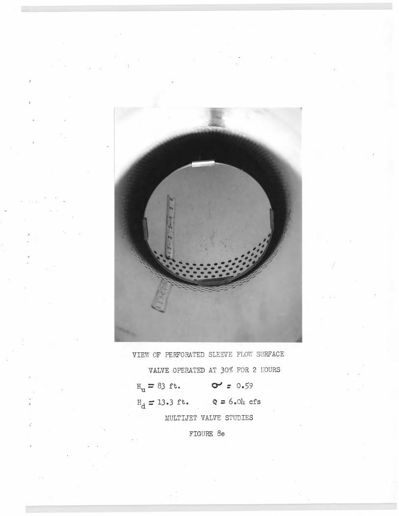
VIF,', OF PERFORATED SLEEVE FLOI SURFACE
VALVE OPERATED AT 30- FOR 2 IOURS
Hu = 83 f t. C3-1 = 0.59
Hd = 13.3 ft. 0 = 6,01 cfs
MULTIJET VALVE STUDIES
FIGURE 8e

3 in. by 102 in. STEEL SPECIMEN COATED
WITH CONCRETE CURING COAMPOUDTD AND
TESTED IN VENTURI CAVITATION TEST
FACILITY. TEST DURATION 1 HOUR
lfULTIJET VALUE STUDIES
FIGt RE 9

IN
A
Pt