HYDRAULIC INTERACTION OF THE PERFORATED SEAWALL … · HYDRAULIC INTERACTION OF THE PERFORATED...
15
13 th International Symposium on Water Management and Hydraulic Engineering, September 9 - 12, 2013 Bratislava, Slovakia HYDRAULIC INTERACTION OF THE PERFORATED SEAWALL AND SMOOTH SUBMERGED BREAKWATER D. Carevic 1 , G. Loncar 2 , M. Paladin 3 Abstract Coastal structures are used for transition of people and goods between sea and land and for protection of coast and internal waters. With an aim to provide safe transition of people and goods, calm sea should be ensured in front of coastline in order to achieve vessels without large movements and no-overtopping coastline. This work deals with special type of coastal structure which consists of two common types of structures: perforated seawall and submerged breakwater positioned in front of it. A new mathematical model was developed based on the experimental measurements of wave parameters between such tandem. Experimental investigations were conducted in wave channel for monochromatic and spectral waves varying length between constructions (1,2m, 2,4m i 6,2m) and submergence of breakwater (0,06m and 0,1m). The total of 54 hydraulic tests were achieved varying wave and geometrical parameters. Using a new developed mathematical models for monochromatic and spectral waves the analyse of hydraulic behaviour of such construction is presented and comparison with some other coastal constructions (only solid seawall, solid seawall in tandem with submerged smooth breakwater). Keywords hydraulic interaction, submerged breakwater, perforated seawall. 1 Dr. D. Carevic, Kaciceva 26, +385915008005, [email protected] 2 Prof. G. Loncar, Kaciceva 26, +38514864 448, [email protected]. 3 M. Paladin, Kaciceva 26, +38514864 451, [email protected].
Transcript of HYDRAULIC INTERACTION OF THE PERFORATED SEAWALL … · HYDRAULIC INTERACTION OF THE PERFORATED...
13th International Symposium on Water Management and Hydraulic Engineering, September 9 - 12, 2013 Bratislava, Slovakia
HYDRAULIC INTERACTION OF THE PERFORATED SEAWALL
AND SMOOTH SUBMERGED BREAKWATER
D. Carevic1, G. Loncar
2, M. Paladin
3
Abstract
Coastal structures are used for transition of people and goods between sea and land and for
protection of coast and internal waters. With an aim to provide safe transition of people and
goods, calm sea should be ensured in front of coastline in order to achieve vessels without
large movements and no-overtopping coastline.
This work deals with special type of coastal structure which consists of two common types of
structures: perforated seawall and submerged breakwater positioned in front of it. A new
mathematical model was developed based on the experimental measurements of wave
parameters between such tandem. Experimental investigations were conducted in wave
channel for monochromatic and spectral waves varying length between constructions (1,2m,
2,4m i 6,2m) and submergence of breakwater (0,06m and 0,1m). The total of 54 hydraulic
tests were achieved varying wave and geometrical parameters.
Using a new developed mathematical models for monochromatic and spectral waves the
analyse of hydraulic behaviour of such construction is presented and comparison with some
other coastal constructions (only solid seawall, solid seawall in tandem with submerged
smooth breakwater).
Keywords
hydraulic interaction, submerged breakwater, perforated seawall.
1 Dr. D. Carevic, Kaciceva 26, +385915008005, [email protected]
2 Prof. G. Loncar, Kaciceva 26, +38514864 448, [email protected].
3 M. Paladin, Kaciceva 26, +38514864 451, [email protected].
WMHE 2013, September 9 - 12, 2013 Bratislava, Slovakia 2
1 INTRODUCTION
Perforated seawall is sea defence construction which attenuates reflected waves and reduces
amount of overtopping. Submerged breakwater causes wave breaking in front of the sea line
and reduces wave energy which approach to seawall (in this work perforated seawall).
Combination of this two structures provide attenuation of wave heights between them and
consequently reduction of the seawall toe erosion, calm sea for berthed vessels and lower
seawall crown.
The original descriptions of the perforated seawall hydraulic behaviour, based on heuristic
approach, have been published in work [1]. A theoretical model, based on long wave theory,
was developed in paper [2], for transmission and reflection coefficient calculation. The model
assumed two parallel perforated walls without back wall, and superposition of linear incident
and reflected waves. In work [3], a simple analytical model for regular waves was developed
predicted for the calculation of the perforated wall reflection coefficients consisted of one
perforated and one solid wall. Deriving a several mathematical models in [4], [5] and [6], for
reflection characteristics estimation, authors have included complex caisson geometry,
influence of foundation embankment and irregular waves. Some other works which deal with
perforated structures are [7] and [8].
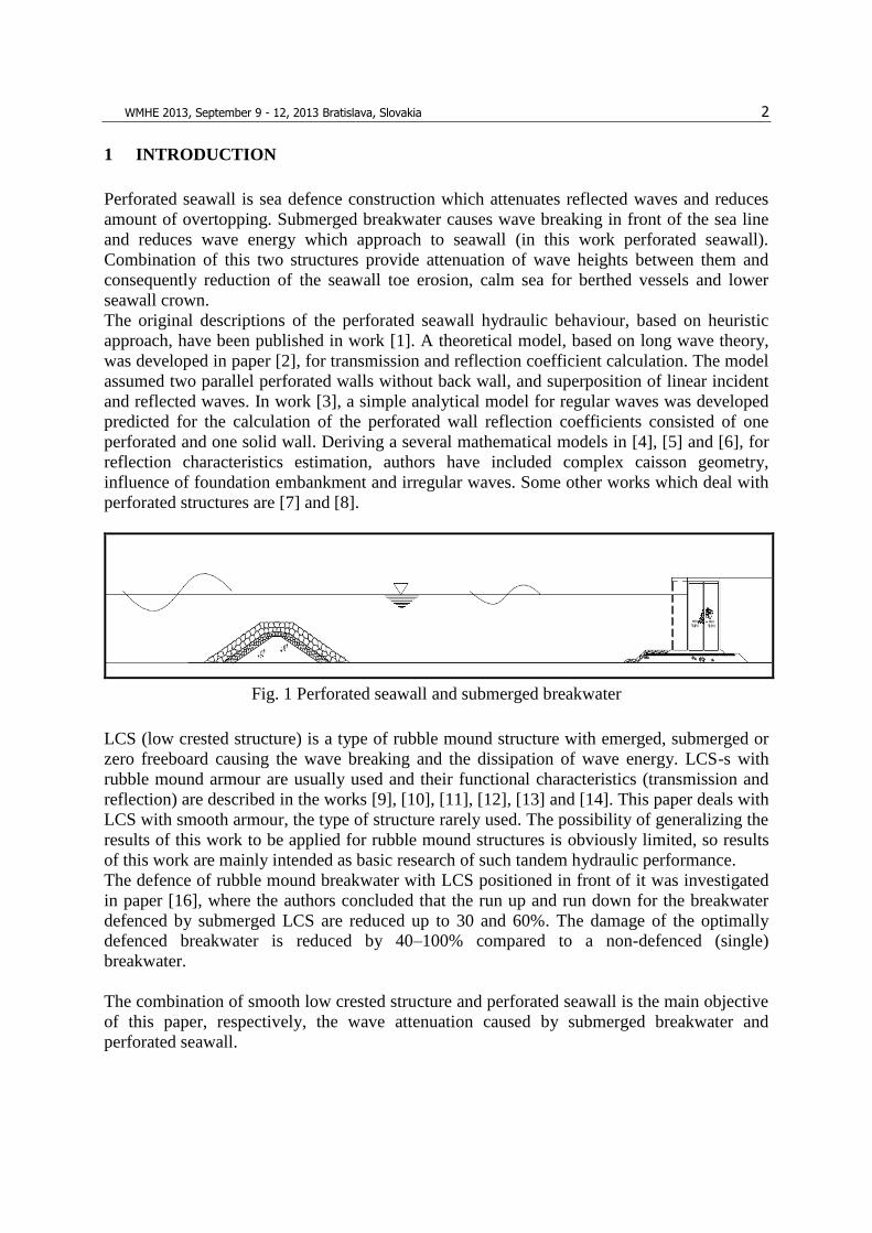
Fig. 1 Perforated seawall and submerged breakwater
LCS (low crested structure) is a type of rubble mound structure with emerged, submerged or
zero freeboard causing the wave breaking and the dissipation of wave energy. LCS-s with
rubble mound armour are usually used and their functional characteristics (transmission and
reflection) are described in the works [9], [10], [11], [12], [13] and [14]. This paper deals with
LCS with smooth armour, the type of structure rarely used. The possibility of generalizing the
results of this work to be applied for rubble mound structures is obviously limited, so results
of this work are mainly intended as basic research of such tandem hydraulic performance.
The defence of rubble mound breakwater with LCS positioned in front of it was investigated
in paper [16], where the authors concluded that the run up and run down for the breakwater
defenced by submerged LCS are reduced up to 30 and 60%. The damage of the optimally
defenced breakwater is reduced by 40–100% compared to a non-defenced (single)
breakwater.
The combination of smooth low crested structure and perforated seawall is the main objective
of this paper, respectively, the wave attenuation caused by submerged breakwater and
perforated seawall.

WMHE 2013, September 9 - 12, 2013 Bratislava, Slovakia 3
2 THEORETICAL MODEL
2.1 Theoretical Model for the Calculation of Wave Heights between Perforated
Seawall and Smooth Submerged Low Crested Structure
The hydraulic interaction of the submerged LCS and the perforated seawall implies the
following: 1. the influence of LCS on the wave heights, and 2. the influence of the perforated
seawall on the wave heights.
Part of the wave energy is transmitted over the submerged breakwater in the form of the
transmitted wave height Ht, (Fig. 2). Those waves travel toward perforated breakwater and
reflect as reflected wave heights Htr. Maximum wave heights which occur between LSC and
perforated seawall are equal to summation of transmitted and reflected wave heights for
regular waves (as it is indicated on Fig. 2).
Fig. 2. Definition sketch of smooth submerged LCS and perforated seawall interaction for
regular waves
Irregular waves are usually described by spectral and statistical methods. Short-term wave
situation is defined by wave energy spectral density function Sh(f). In the case of opposite
direction traveling waves, the superposed significant wave height (Hs-sup) could be calculated
according to [18] as it is indicated on Fig. 3.
WMHE 2013, September 9 - 12, 2013 Bratislava, Slovakia 4
Fig. 3 Definition sketch of smooth submerged LCS and perforated seawall interaction for
irregular waves
Transmission over the breakwater and reflection from seawall depend on geometrical
characteristics and incident waves parameters. Both phenomena are well described by existing
mathematical models. In this work, existing mathematical models for submerged breakwater
(chapter 2.3) and perforated seawall (chapter 2.2) will be used for a new mathematical model
development, with the aim of the description of the hydraulic performance of such tandem. A
new formed mathematical model will allow calculation of wave heights between submerged
breakwater and perforated seawall for different incident wave parameters and geometries of
structures.
2.2 Theoretical Model for Perforated Seawall Reflection Coefficient Calculation
Regular waves
In the paper [3] authors have derived analytical model for reflection coefficient calculation
based on assumption of regular long-crested waves and constant depth of the water in
dissipation chamber and in front of the perforated wall.
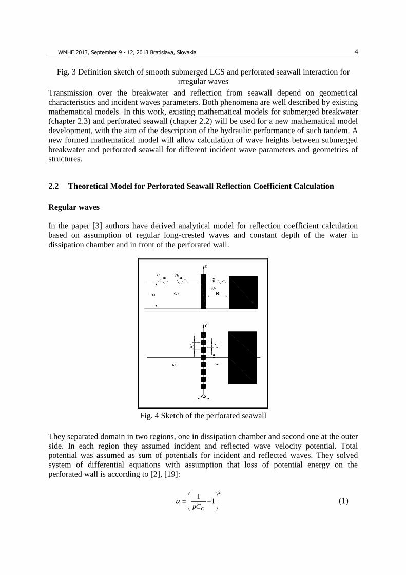
Fig. 4 Sketch of the perforated seawall
They separated domain in two regions, one in dissipation chamber and second one at the outer
side. In each region they assumed incident and reflected wave velocity potential. Total
potential was assumed as sum of potentials for incident and reflected waves. They solved
system of differential equations with assumption that loss of potential energy on the
perforated wall is according to [2], [19]:
2
11
CpC (1)
WMHE 2013, September 9 - 12, 2013 Bratislava, Slovakia 5
where are:
p porosity of perforated wall,
CC contraction coefficient of the jet from the perforation hole, CC=0,4-0,8 according to
[19] and equation 24,06,0 pCC according to [20].
Solving differential equations they have got system of independent linear equations which
give:
222
5,0222222222
)1(
22
RWG
WGRWRWWG
KR
(2)
where are:
lkP (3)
kR (4)
kBW tan (5)
PWG 1 (6)
4
1
1
180
281
1
1
3
1
1
14log1
121
1
1
2
2;2
A
a
A
a
A
aA
a
AACCl
(7)
)2sinh(2
)2cosh(5
)1(9
8
222 kdkd
kd
GRW
WH
(8)
Reflected wave height can then be defined as:
iRr HKH (9)
Irregular waves
Mathematical model for reflection coefficient calculation of irregular waves was developed in
paper [21]. Model is based on above described model for regular waves. Methodology is
based on application of regular wave’s model on each spectral component independently.
Dissipation coefficient b is calculated for each component with a same wave height Hrms-root
mean square wave height. Each component of wave spectrum is denoted with subscript „n“:
222
5,0222222222
)1(
22
nnn
nnnnnnnn
nRRWG
WGRWRWWG
K
(10)
nn lkP (11)

WMHE 2013, September 9 - 12, 2013 Bratislava, Slovakia 6
n
nnn
kR
(12)
BkW nn tan (13)
nnn WPG 1 (14)
)2sinh(2
)2cosh(5
)1(9
8
222 dkdk
dk
GRW
WH
nn
n
nnn
nnrms
(15)
416,1
004,4 0mH rms (16)
where is:
m0 zero momenth of incident wave spectrum, [m2]
If discrete distribution KRn is transformed to continuous curve KR(w), the reflected wave
spectrum can be solved as:
)()()(2
iRr SKS (17)
2.3 Theoretical Model for Calculation of Transmission Coefficients over Smooth LCSs
Fig. 5 Definition of symbols for smooth LCS theoretical model
LCS need not be necessarily covered with rock fill. Sometimes smooth and impermeable LCS
can be covered with asphalt or concrete armour. The slopes of these LCSs are sometimes
more gentle (1:3 or 1:4) than it is the case with the LCS with the stone armour, mostly due to
construction reasons.
The asphalt and concrete LCSs are mostly built in dry conditions, and not under the water.
The presence of tides enables the building of such structure in dry conditions.
Since the smooth LCSs are different in the process of hydraulic functioning than the
breakwaters covered with rock, there are different formulas for the transmission coefficient.
The wave transmission can be calculated according to the paper [15]:

WMHE 2013, September 9 - 12, 2013 Bratislava, Slovakia 7
KT = [-0.3F/Hsi+0.75[1-exp(-0.5)]]cos2/3β (18)
with the minimum KT=0.075 and the maximum KT=0.8, and with the following limitations: 1
< ξ < 3, 0° ≤ β ≤ 70°, 1 < Bv/Hsi < 4. The symbols are :
F -water depth at the crown, [m],
Hsi -significant wave height in front of LCS ( 04 msiH ), [m],
-Irribaren number, 5.0)/( opstg , )2/(2 pgTsiHops ,
Bv -crown width, [m]
Eq.(18) takes the angle wave transmission into consideration by means of the expression
cos2/3
β.
3 PHYSICAL MODEL
3.1 Wave Channel and Measurement Equipment
The experimental research was made in the Laboratory of the Faculty of Civil Engineering in
Zagreb. The wave channel width was 1m, the height was 1.1 m, and the depth of water in the
channel was d=0.5 m.
The measuring equipment includes the piston wave generator with the installed AWACS
system, and the data collection system (sampling frequency 40Hz) produced by DHI
(Horsholm, Denmark). Capacitive gauges (DHI) G1-G8 (Fig. 6) were used for measuring the
surface elevation. The analysis of the collected data was made by means of the system DHI
Wave Synthesizer. The incident wave parameters in front of LCS were determined in the
spectral domain by means of the WS Wave Reflection Analysis. The spectral analyses were
performed with the following parameters: size of FFT block: 512, overlap: 0.667, Number of
subseries: 68, lower cut-off frequency: 0.0 Hz, higher cut-off frequency: 20.0 Hz, Data
window: Hanning method, frequency step: 0.078 Hz.
3.1.1 Physical Model of the Perforated Seawall (inter 0)
A wooden model of the perforated seawall was placed into the wave channel at the distance of
15.7m from the wave generator. The model of the perforated seawall was made of wood with
the porosity of p=30% (p-ratio of the opening and the total surface of the wall) and with
vertical longitudinal openings, and with the width of dissipation chamber of B=0.18m.

WMHE 2013, September 9 - 12, 2013 Bratislava, Slovakia 8
Fig. 6. Longitudinal section of wave channel with capacitive gauges (G1-G8) and perforated
seawall (Model) positions (Inter 0)
Tab. 1 Wave parameters used in experiments without LCS (inter 0) and with LCS (inter 1-6)
3.1.2 Physical Model of the Perforated Seawall and Submerged Smooth LCS Interaction
(inter 1-6)
The model of the smooth submerged breakwater was made of wood with the crown width of
Bv=0,16m, the slopes of 1:2 and the possibility to change the submergence depth so that two
depths 0.055m and 0.101m can be achieved (Fig. 7).
Fig. 7. Photographs of submerged low crested structure (LCS) positioned in channel for
crown submergence F=0.055m
WMHE 2013, September 9 - 12, 2013 Bratislava, Slovakia 9
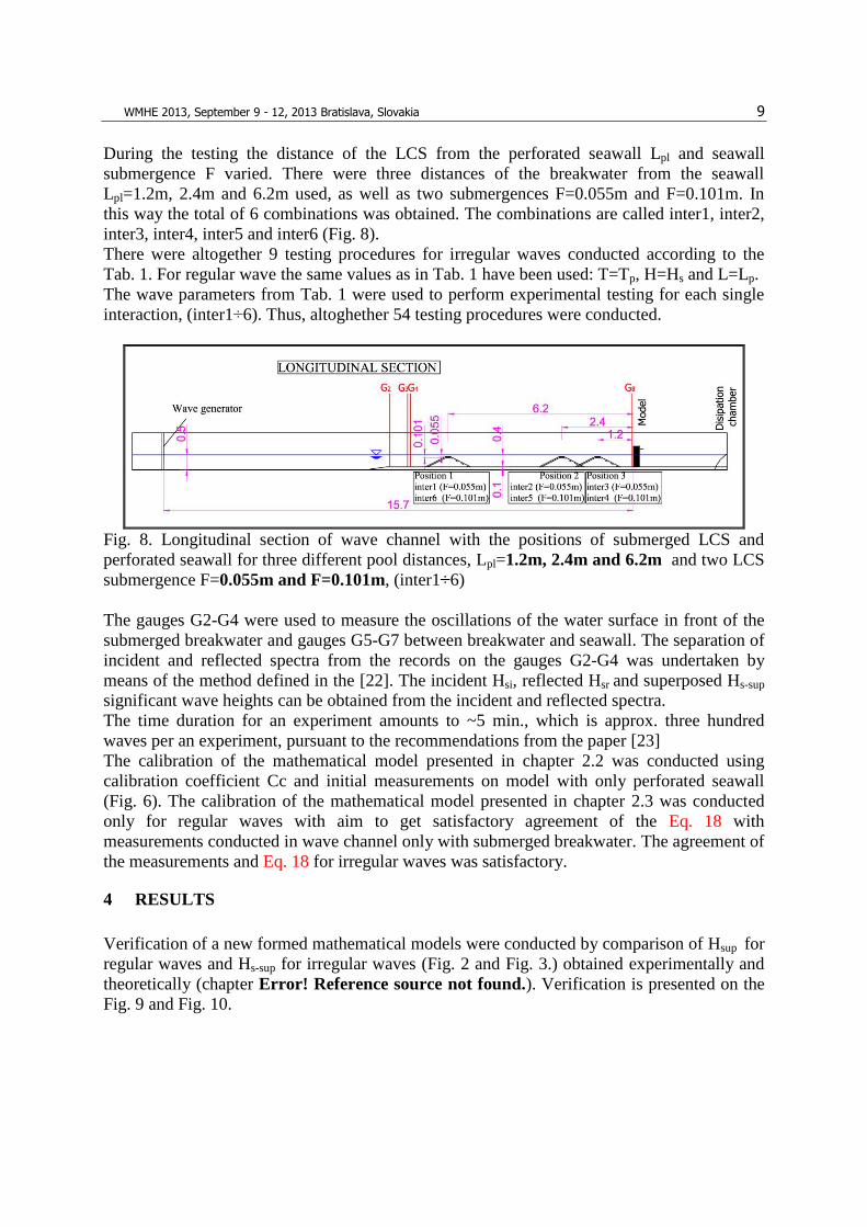
During the testing the distance of the LCS from the perforated seawall Lpl and seawall
submergence F varied. There were three distances of the breakwater from the seawall
Lpl=1.2m, 2.4m and 6.2m used, as well as two submergences F=0.055m and F=0.101m. In
this way the total of 6 combinations was obtained. The combinations are called inter1, inter2,
inter3, inter4, inter5 and inter6 (Fig. 8).
There were altogether 9 testing procedures for irregular waves conducted according to the
Tab. 1. For regular wave the same values as in Tab. 1 have been used: T=Tp, H=Hs and L=Lp.
The wave parameters from Tab. 1 were used to perform experimental testing for each single
interaction, (inter1÷6). Thus, altoghether 54 testing procedures were conducted.
Fig. 8. Longitudinal section of wave channel with the positions of submerged LCS and
perforated seawall for three different pool distances, Lpl=1.2m, 2.4m and 6.2m and two LCS
submergence F=0.055m and F=0.101m, (inter1÷6)
The gauges G2-G4 were used to measure the oscillations of the water surface in front of the
submerged breakwater and gauges G5-G7 between breakwater and seawall. The separation of
incident and reflected spectra from the records on the gauges G2-G4 was undertaken by
means of the method defined in the [22]. The incident Hsi, reflected Hsr and superposed Hs-sup
significant wave heights can be obtained from the incident and reflected spectra.
The time duration for an experiment amounts to ~5 min., which is approx. three hundred
waves per an experiment, pursuant to the recommendations from the paper [23]
The calibration of the mathematical model presented in chapter 2.2 was conducted using
calibration coefficient Cc and initial measurements on model with only perforated seawall
(Fig. 6). The calibration of the mathematical model presented in chapter 2.3 was conducted
only for regular waves with aim to get satisfactory agreement of the Eq. 18 with
measurements conducted in wave channel only with submerged breakwater. The agreement of
the measurements and Eq. 18 for irregular waves was satisfactory.
4 RESULTS
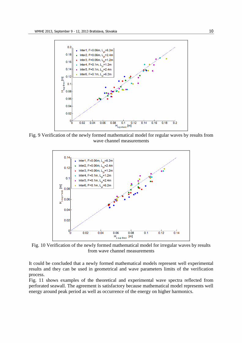
Verification of a new formed mathematical models were conducted by comparison of Hsup for
regular waves and Hs-sup for irregular waves (Fig. 2 and Fig. 3.) obtained experimentally and
theoretically (chapter Error! Reference source not found.). Verification is presented on the
Fig. 9 and Fig. 10.
WMHE 2013, September 9 - 12, 2013 Bratislava, Slovakia 10
Fig. 9 Verification of the newly formed mathematical model for regular waves by results from
wave channel measurements
Fig. 10 Verification of the newly formed mathematical model for irregular waves by results
from wave channel measurements
It could be concluded that a newly formed mathematical models represent well experimental
results and they can be used in geometrical and wave parameters limits of the verification
process.
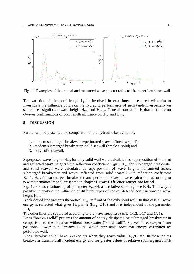
Fig. 11 shows examples of the theoretical and experimental wave spectra reflected from
perforated seawall. The agreement is satisfactory because mathematical model represents well
energy around peak period as well as occurrence of the energy on higher harmonics.
WMHE 2013, September 9 - 12, 2013 Bratislava, Slovakia 11
Fig. 11 Examples of theoretical and measured wave spectra reflected from perforated seawall
The variation of the pool length Lpl is involved in experimental research with aim to
investigate the influence of Lpl on the hydraulic performance of such tandem, especially on
superposed significant wave height Hsup and Hs-sup. General conclusion is that there are no
obvious confirmations of pool length influence on Hsup and Hs-sup.
5 DISCUSSION
Further will be presented the comparison of the hydraulic behaviour of:
1. tandem submerged breakwater+perforated seawall (breakw+perf),
2. tandem submerged breakwater+solid seawall (breakw+solid) and
3. only solid seawall.
Superposed wave heights Hsup for only solid wall were calculated as superposition of incident
and reflected wave heights with reflection coefficient KR=1. Hsup for submerged breakwater
and solid seawall were calculated as superposition of wave heights transmitted across
submerged breakwater and waves reflected from solid seawall with reflection coefficient
KR=1. Hsup for submerged breakwater and perforated seawall were calculated according to
new mathematical model presented in chapter Error! Reference source not found..
Fig. 12 shows relationship of parameter Hsup/Hi and relative submergence F/Hi. This way is
possible to analyse the influence of different types of coastal defence constructions on wave
height Hsup.
Black dotted line presents theoretical Hsup in front of the only solid wall. In that case all wave
energy is reflected what gives Hsup/Hi=2 (Hsup=2 Hi) and it is independent of the parameter
F/Hi.
The other lines are separated according to the wave steepness (H/L=1/12, 1/17 and 1/25).
Lines “breakw+solid” presents the amount of energy dissipated by submerged breakwater in
comparison to the situation without breakwater (“solid wall”). Curves “breakw+perf” are
positioned lower than “breakw+solid” which represents additional energy dissipated by
perforated wall.
Lines “breakw+solid” have breakpoints when they reach value Hsup/Hi =2. In those points
breakwater transmits all incident energy and for greater values of relative submergences F/Hi

WMHE 2013, September 9 - 12, 2013 Bratislava, Slovakia 12
the tandem “breakw+solid” behaves like only solid wall. The same breakpoints are visible on
curves “breakw+perf”. Curvature of the curves “breakw+perf” is resulted because the
reflection coefficients of the perforated seawall depend on the incoming wave lengths. The
function of the reflection coefficient in relationship to incoming wave height (and length) has
parabolic shape.
Colored dotted curves represent limits of the parameter Hsup/Hi for the variation of the input
wave heights within Hi1.1 = 1.1 · Hi and Hi0.9 = 0.9 · Hi.
The agreement between measurements and curves “breakw+perf” are satisfactory and it can
be concluded that newly formed mathematical model describe well hydraulic behaviour of the
submerged smooth breakwater and perforated seawall.
The same presentation as those on Fig. 12 could be produced but for submergence F=0.1m.
Because of similarity with Fig. 12 this presentation is omitted.
Fig. 12 Comparison of the parameter Hsup/Hi for only solid seawall, tandem submerged
breakwater and solid seawall (breakw+solid), tandem submerged breakwater and perforated
seawall (breakw+perf), F=0.06m, regular waves, “o”-measurements, “∙∙∙∙”- upper limit for
1.1∙Hi and lower limit for 0.9∙Hi
Fig. 13 shows the same as previous figure but for irregular waves. It is visible that in case of
irregular waves parameter Hs-sup/Hsi can be maximum 1.41 what is in accordance to
measurements presented in [18]. In the case of the irregular waves the assumption of the
superposition of wave energies is valid (Fig. 3) unlike in case of the regular waves where the
assumption of the summation of the wave heights is valid (Fig. 2.)
In case of the irregular waves the influence of the perforated seawall on the energy dissipation
is less than in the case of the regular waves. That is visible from fact that curves for
“breakw+perf” are at lower position from “breakw+solid” in case of the regular waves. The

WMHE 2013, September 9 - 12, 2013 Bratislava, Slovakia 13
main reason is in fact that presentation with spectral parameters as significant wave heights,
includes all components from wave spectra which reflects with different reflection coefficient,
which finally gives smaller influence of the perforated seawall.
Fig. 13 Comparison of the parameter Hs-sup/Hsi for only solid seawall, tandem submerged
breakwater and solid seawall (breakw+solid), tandem submerged breakwater and perforated
seawall (breakw+perf), F=0.06m, irregular waves, “o”-measurements, “∙∙∙∙”- upper limit for
1.1∙Hsi and lower limit for 0.9∙Hsi
6 CONCLUSION
The experimental investigation, in wave channel, of the smooth submerged breakwater and
perforated seawall is conducted with aim to form the mathematical model for calculation of
the superposed wave heights between them. The mathematical model is formed from existing
models for each type of construction. The verification of a newly formed mathematical model
is conducted using results from measurements in wave channel.
Generally, the influence of the submerged breakwater on the energy dissipation is greater than
the influence of the perforated seawall, if submergence F is small enough. The submerged
breakwaters are cheap rubble mound constructions unlike reinforced concrete perforated
seawalls. This leads to conclusion that the application of the submerged breakwater with the
crown close to the zero water level in combination with solid seawall is better solution. Only
in special cases with great tide oscillations and specific requests on submerged crown, the
application of submerged breakwater and perforated seawall is acceptable.
WMHE 2013, September 9 - 12, 2013 Bratislava, Slovakia 14
References
[1] Marks, M.; Jarlan, G. E.: Experimental study on a fixed perforated breakwater, Proc.
11th Coastal Engineering Conference, III, (1968), ASCE, 1121-1140
[2] Kondo, H. Analysis of breakwater having two porous walls. Coastal Structures '79., II,
ASCE, (1979).; 962-977.
[3] Fugazza, M.; Natale, L.: Hydraulic design of perforated breakwaters, Journal of
Waterway, Port, Coastal, and Ocean Engineering, vol. 118, No. 1, (1992)
[4] Suh, Kyumg-Duck; Park, Jae Kil; Park, Woo Sun: Wave reflection from partially
perforated-wall caisson breakwater; Ocean Engineering 33 (2006), 264-280.
[5] Suh, Kyung Doug; Choi, Jae Chun; Kim, Bum Hyoung; Park, Woo Sun; Lee, Kil Seong:
Reflection of irregular waves from perforated-wall caisson breakwaters; Coastal
Engineering 44 (2001); 141-151
[6] Suh, K. D., Park, W. S., Wave reflection from perforated-wall caisson breakwaters,
Coastal Engineering 26, (1995), 177–193
[7] Sawaragi, T.; Iwata, K.: Irregular wave attenuation due to a vertical barrier with air
chamber Coastal Structures 79, ASCE, (1979); 29-47
[8] Allsop, N.W.H; Hettiarachichi S. S. L.: Wave reflections in harbours: design,
construction and performance of wave absorbing structures; Report OD 89, HR
Wallingford, (1989)
[9] D’Angremond, K., Van der Meer, de Jong, R.J. Wave transsmision at low-crested
structure; ASCE, Proc. ICCE, Orlando, (1996), Florida, 3305-3318.
[10] Seabrook, S. R., Hall, K. R.: Wave transsmision at submerged rubble mound
breakwaters; Proc. 26TH Int. Conf. on Coast. Engineering, (1998), ASCE, 2000-2013.
[11] Buccino, M., Calabrese, M.: Conceptual approach for prediction of wave transmission at
low-crested breakwaters; Journal of waterway, port, coastal, and ocean engineering ,
(2007),ASCE, May/June.
[12] Van der Meer, J.W., Wang, B., Wolters, A., Zanuttigh, B., Kramer, M.: Oblique wave
transmission over low-crested structures, ASCE, Proc. Coastal Structures, Portland,
Oregon, (2003).
[13] Van der Meer, J.W., Regeling, H.J., de Waal, J.P.: Wave transmission: spectral changes
and its effect on run-up and overtopping, ASCE, Proc.ICCE, , Sydney, Australia,2156-
2168, (2000).
[14] Briganti, R., Van der Meer, J.W., Buccino, M., Calabrese, M.: Wave transmission behind
low crested structures, ASCE, Proc. Coastal Structures, Portland, Oregon (2003).
[15] Van der Meer, J.W., Wang, B., Wolters, A., Zanuttigh, B., Kramer, M.: Oblique wave
transmission over low-crested structures, ASCE, Proc. Coastal Structures, Portland,
Oregon, (2003).
[16] Shirlal, K. G., Rao, S., Ganesh, V., Manu: Stability of breakwater defencedby a seaward
submerged reef. Ocean Engineering, 33. (2006) 829–846
[17] Hughes, S. A.: Physical models and laboratory techniques in coastal engineering,
Advanced Series on Ocean Engineering-Volume7, World Scientific, 1993, pp. 502-506.
[18] Goda, Y., Random seas and design of maritime structures, (2nd Edition), World
Scientific Publishing, (2000), 103-105.
[19] Hattori, M.: Transmission of waves through perforated wall, Coastal Engineering in
Japan, 15, (1972),69-79

WMHE 2013, September 9 - 12, 2013 Bratislava, Slovakia 15
[20] Mei, C. C., Liu, P.L.-F., Ippen, A.T.: ''QUADRATIC LOSS AND SCATTERING OF
LONG WAVES'', Journal of Waterways, Harbours Coastal Engineering Division, ASCE,
(1974), 100, 217-239
[21] Suh, Kyung Doug; Son, Sang Young; Lee, Jong In; Lee, Tae Hwan: ''CALCULATION
OF IRREGULAR WAVE REFLECTION FROM PERFORATED-WALL CAISSON
BREAKWATERS USING A REGULAR WAVE MODEL'', Coastal Engineering,
(2002): Solving Coastal Conundrums: Proceedings of the 28th International Conference :
7-12 July 2002, Cardiff Hall, Cardiff Wales, Jan Smith McKee
[22] Zelt, J. A., Skjelbreia, J. E.: ''ESTIMATING INCIDENT AND REFLECTED WAVE
FIELDS USING AN ARBITRARY NUMBER OF WAVE GAUGES'', Coastal
Engineering, (2002)
[23] Journée, J.M.J., Massie, W.W., 2001. Offshore Hydromechanics, First Edition, Delft
University of Technology, http://www.shipmotions.nl, 5-43,


![KD-A645 / KD-R640 / KD-R540 / KD-R440 - Car Audio ...santafeautosound.com/uploads/product-manuals/JVC KD-R540.pdfKD-A645 / KD-R640 / KD-R540 / KD-R440 GET0829-001A [J/JW] ENGLISH ESPAÑOL](https://static.fdocuments.in/doc/165x107/5aaf5da87f8b9a25088d67c4/kd-a645-kd-r640-kd-r540-kd-r440-car-audio-kd-r540pdfkd-a645-kd-r640.jpg)