dkcsmolyan.com · ücmßgre 3aropa pcsa ce 110 6aHICOB 1ThT, B cp01

HYDRAULIC EXCAVATORModel Code: ZX 470LCH-3 Engine Rated Power: 260 kW (349 hp)Operating Weight: 48 100 kgBackhoe Bucket: SAE, PCSA Heaped: 1.9 - 2.65 m3
CECE Heaped: 1.7 - 2.3 m3
ZAXIS-3 series

Machine is equipped with H/R cab.
�
The New Generation Hydraulic ExcavatorsThe HITACHI ZAXIS-3 series new-generation hydraulic excavators are packed with a host of technological features - clean engine, HITACHI advanced hydraulic technologies, with strong undercarriage and front attachment, plus well matching of power and speed. The ZAXIS-3 series can get the job done with proven productivity, durability, and reliability, especially in heavy-duty excavation and quarry operations.

�
Clean engine complies with the emission regulations US EPA Tier 3 and EU Stage III A
Low noise design complies with the EU noise regulation 2000 / 14 / EC, STAGE II

Machine is equipped with H/R cab.
�
Production: Approx. 14% Increase
Fuel Consumption: Approx. 13% Reduction (vs. Conventional Model)
World-Class Productivity To yield high production yet maintain low fuel consumption, such was the objective of the development of a new engine and hydraulic system for the ZAXIS 470LCH.
�
Advanced Hydraulic Technologies
Increased Digging Force 7% more bucket digging force and 8% more arm digging force*.
* At power boost mode / vs Conventional model
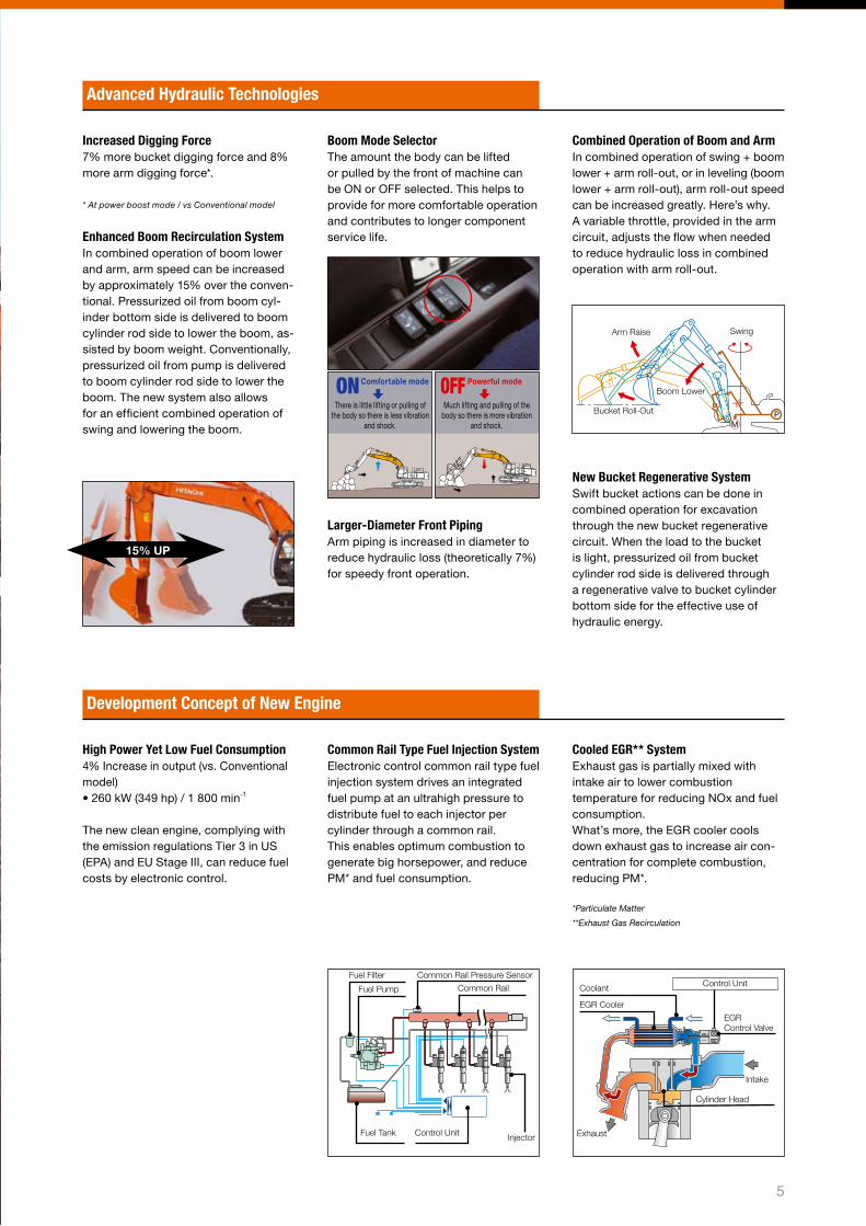
Enhanced Boom Recirculation System In combined operation of boom lower and arm, arm speed can be increased by approximately 1�% over the conven-tional. Pressurized oil from boom cyl-inder bottom side is delivered to boom cylinder rod side to lower the boom, as-sisted by boom weight. Conventionally, pressurized oil from pump is delivered to boom cylinder rod side to lower the boom. The new system also allows for an efficient combined operation of swing and lowering the boom.
15% UP
Boom Mode Selector The amount the body can be lifted or pulled by the front of machine can be ON or OFF selected. This helps to provide for more comfortable operation and contributes to longer component service life.
Larger-Diameter Front Piping Arm piping is increased in diameter to reduce hydraulic loss (theoretically 7%) for speedy front operation.
Combined Operation of Boom and Arm In combined operation of swing + boom lower + arm roll-out, or in leveling (boom lower + arm roll-out), arm roll-out speed can be increased greatly. Here’s why. A variable throttle, provided in the arm circuit, adjusts the flow when needed to reduce hydraulic loss in combined operation with arm roll-out.
New Bucket Regenerative System Swift bucket actions can be done in combined operation for excavation through the new bucket regenerative circuit. When the load to the bucket is light, pressurized oil from bucket cylinder rod side is delivered through a regenerative valve to bucket cylinder bottom side for the effective use of hydraulic energy.
PM
Arm Raise
Bucket Roll-Out
Swing
Boom Lower
Development Concept of New Engine
High Power Yet Low Fuel Consumption �% Increase in output (vs. Conventional model) • �60 kW (��9 hp) / 1 800 min-1
The new clean engine, complying with the emission regulations Tier � in US (EPA) and EU Stage III, can reduce fuel costs by electronic control.
Common Rail Type Fuel Injection SystemElectronic control common rail type fuel injection system drives an integrated fuel pump at an ultrahigh pressure to distribute fuel to each injector per cylinder through a common rail.This enables optimum combustion to generate big horsepower, and reduce PM* and fuel consumption.
Cooled EGR** SystemExhaust gas is partially mixed with intake air to lower combustion temperature for reducing NOx and fuel consumption. What’s more, the EGR cooler cools down exhaust gas to increase air con-centration for complete combustion, reducing PM*.
*Particulate Matter
**Exhaust Gas Recirculation
Fuel Filter
Fuel Pump
Common Rail Pressure Sensor
Common Rail
Fuel Tank Control Unit Injector
Coolant
EGR Cooler
Control Unit
Intake
EGR Control Valve
Cylinder Head
Exhaust
ONComfortable mode
There is little lifting or pulling of the body so there is less vibration
and shock.
OFF Powerful mode
Much lifting and pulling of the body so there is more vibration
and shock.

6
A Solid Base for a Long Life Strengthened undercarriage for higher durability even in heavy-duty applications.

7
Strengthened Undercarriage
Increased Loading Capacity of Swing Circle The swing circle ball bearing utilizes more balls to boost the loading capacity of the swing circle by approximately 6%, allowing stable swing even in tough operation*.
Strengthened Track Links The boss diameter of each track link is increased by approximately 19%. The thickness of each track link is also increased by approximately �7%. Thickened track links extend service life*.
* vs. Conventional model
Strengthened Upper Roller Bracket The upper roller bracket wall thickness is increased for higher strength.
Full Track Guard (Optional) Full track guards protect track links and lower rollers from damage and deformation. Moreover, they also keep out stones, preventing the overload to the undercarriage to reduce wear and damage.
Pressed Master Pins The master pin of each track link is pressed, instead of the master pin using a pin retention to avoid disengagement.
Strengthened Idler Pedestal The bearing length of the idler pedestal is extended by approximately 67% to increase durability and service life*.
Improved Idler Bracket The idler bracket is thickened for rigid-ity to prevent deformation and increase durability.
Strengthened Front Attachment
5% Increase in Strength with Stronger Pin Material The strength of pins, used in the arm and boom, is increased by �%, using harder steel material*.
* vs. Conventional model
Strengthened General-Purpose Bucket Bucket teeth are reshaped as Super-V teeth for smooth penetration and higher production. Bushings are utilized at both ends of a bucket pin to eliminate clearances, preventing jerky operation.
Strengthened H-Bucket for Heavy-Duty The heavy-duty bucket is reshaped, and bucket parts are strengthened to increase durability.

8
A New Standard in Operator Comfort The spacious cab is ergonomically designed with excellent visibility to reduce operator fatigue and burden. The operator seat is ergonomically designed for long-hour pleasant operation.

9
Maintenance SupportThe LCD monitor alerts the operator of the replacement timing of hydraulic oil and fuel filters according to user’s setting, at each time when turning on the key switch. This scheduled maintenance can prevent machine failure.
Fuel Consumption MonitoringFuel consumption per operating hour can be computed, and the result is displayed on the LCD monitor. This information suggests refueling timing, and assists in energy-saving operation and efficient job management.
Theft Deterrent System (Optional)The electronic immobiliser requires theentry of an encryption code to themulti-function monitor each time whenstarting the engine to prevent theft andvandalism.
Multi-Function Monitor, Multi-Language SelectionA large multi-language, multi-function monitor is well positioned for easy reading.
Rear View Camera The large color LCD monitor, teamed up with the rear view camera on the counterweight, gives the operator un-obstructed rearward view. This system enhances safety during swing and reversing.
Attachment Support System(work mode selector) The work mode can be selected from the multi-function monitor inside the cab. Pump flow in the selected work mode can be monitored.
Excavation: Work mode selection window
Breaker 1: Selected for small-flow breaker
Breaker 2: Selected for medium-flow breaker
Breaker 3: Selected for large-flow breaker
Excellent Visibility The glass windows are widened for excellent visibility, especially improving right downward view during travel and excavation.
Ample Foot Space Foot space is expanded forward, and pedals are reshaped for pleasant operation.
Short-Stroke Levers Fingertip control of short-stoke levers, with the help of armrests, allows long, continuous operation with less fatigue. • �0% reduction in lever control effort*.
*vs. Conventional model
Comfort-Designed Operator Seat The seatback is widened to hold the operator securely, and the headrest is reshaped. The operator seat is strengthened to reduce vibration and shocks, and increase durability.
Fluid-Filled Elastic Mounts The cab rests on fluid-filled elastic mounts that absorb shocks and vibra-tion to enhance operator comfort.
Pressurized CabThe pressurized cab shuts out debris and dirt.
Miscellaneous Cab Accessories
Generous Storage Space Personal Storage Space
Drink Holder Hot & Cool Box
Control Panel Full-Auto Air Conditioner and AM/FM Radio
Rear View Camera

10
The radiator and oil cooler are laid out in parallel arrangement for easy demounting, instead of conventional in-line arrangement. This new arrange-ment significantly helps facilitate clean-ing around the engine.
Air-conditioner fresh-air filters are relocat-ed to the cab door side from conventional location behind the operator seat. This fa-cilitates cleaning and replacement of fresh-air filters, like air-conditioner circulation-air filters inside the cab.
Parallel Arrangement of the Cooling Pack
Simplified Maintenance Focusing on simplified maintenance, including easy inspection, service and cleaning.
Simplified Cleaning around Engine
Air-Conditioner Fresh-Air Filters
Machine is equipped with H/R cab.
Easy removal of debris and dirt from blower, etc. Engine
Radiator Oil Cooler
Intercooler
Parallel Arrangement
11
Simplified Maintenance
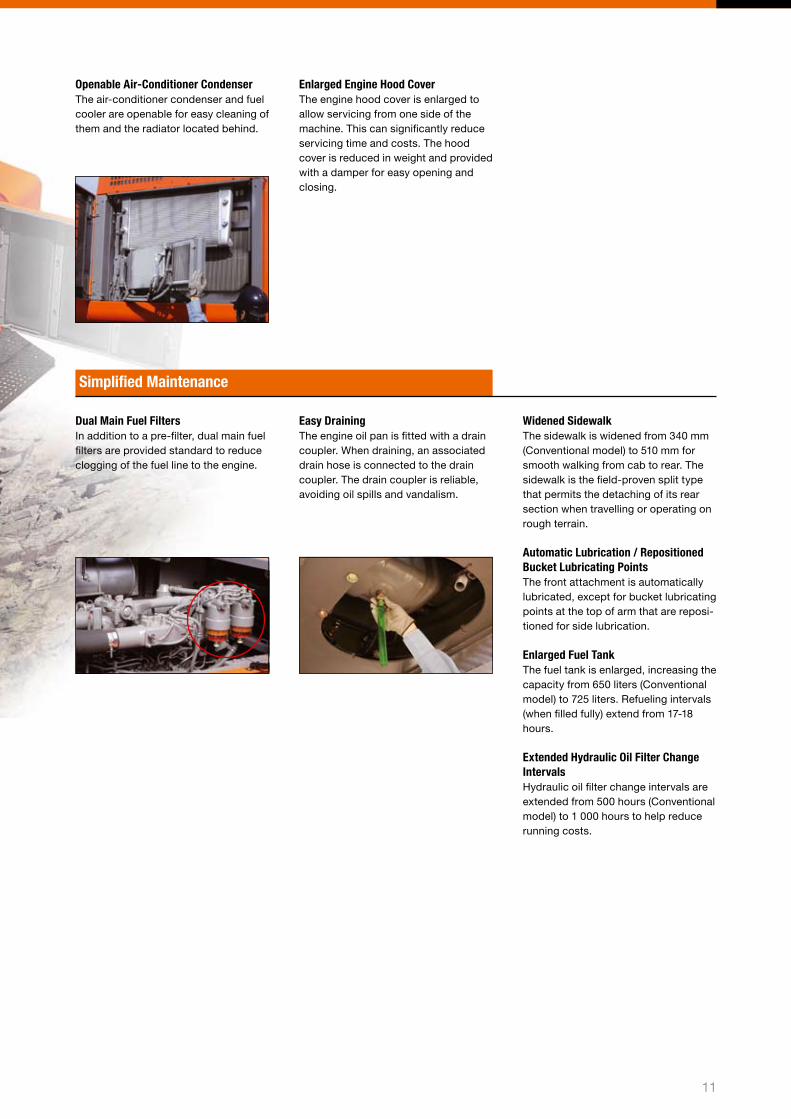
Openable Air-Conditioner Condenser The air-conditioner condenser and fuel cooler are openable for easy cleaning of them and the radiator located behind.
Enlarged Engine Hood Cover The engine hood cover is enlarged to allow servicing from one side of the machine. This can significantly reduce servicing time and costs. The hood cover is reduced in weight and provided with a damper for easy opening and closing.
Dual Main Fuel Filters In addition to a pre-filter, dual main fuel filters are provided standard to reduce clogging of the fuel line to the engine.
Widened Sidewalk The sidewalk is widened from ��0 mm (Conventional model) to �10 mm for smooth walking from cab to rear. The sidewalk is the field-proven split type that permits the detaching of its rear section when travelling or operating on rough terrain.
Automatic Lubrication / Repositioned Bucket Lubricating Points The front attachment is automatically lubricated, except for bucket lubricating points at the top of arm that are reposi-tioned for side lubrication.
Enlarged Fuel Tank The fuel tank is enlarged, increasing the capacity from 6�0 liters (Conventional model) to 7�� liters. Refueling intervals (when filled fully) extend from 17-18 hours.
Extended Hydraulic Oil Filter Change IntervalsHydraulic oil filter change intervals are extended from �00 hours (Conventional model) to 1 000 hours to help reduce running costs.
Easy Draining The engine oil pan is fitted with a drain coupler. When draining, an associated drain hose is connected to the drain coupler. The drain coupler is reliable, avoiding oil spills and vandalism.
1�
Boarding Clean EngineA clean engine complying with the emission regulations Stage III in EU and Tier � in US (EPA) is boarded to reduce emissions containing nitrogen oxide (NOx) and particulate matter (PM).
Low Noise EngineEngine noise is reduced by approximately � dB with the robust engine. It goes without saying that the engine meets the EU noise regulations.
Variable-Speed Fan The engine cooling fan is a large 1 1�0 mm diameter variable-speed electro-hydraulic fan. This fan automati-cally starts when temperature comes into the high temperature range, ensuring low noise operation.
Proven Muffler A proven large muffler is provided to reduce sound and exhaust emissions greatly.
Using Aluminum Radiator, Oil Cooler and Air-Conditioner CondenserThe aluminum radiator, oil cooler and air-conditioner condenser are utilized for the sake of recycling and for in-creased durability.
Marking of Recyclable Parts All resin parts are marked for the sake of recycling. This helps ease the sepa-ration of recyclable wastes.
Reducing the Burden to the Environment Lead-free design is achieved through the use of lead-free wire harness cover-ing, radiator, oil cooler and others. No asbestos is used. The use of aluminum radiator, oil cooler and intercooler in-creases the durability of the machine.
Biodegradable Hydraulic Oil (Optional)Degradable hydraulic oil is ecological, which is decomposed into water and carbon dioxide in water and ground.
Environmental Features Boarding a clean engine complying with the rigorous emission regulations.
Environmentally Friendly Designs
1�
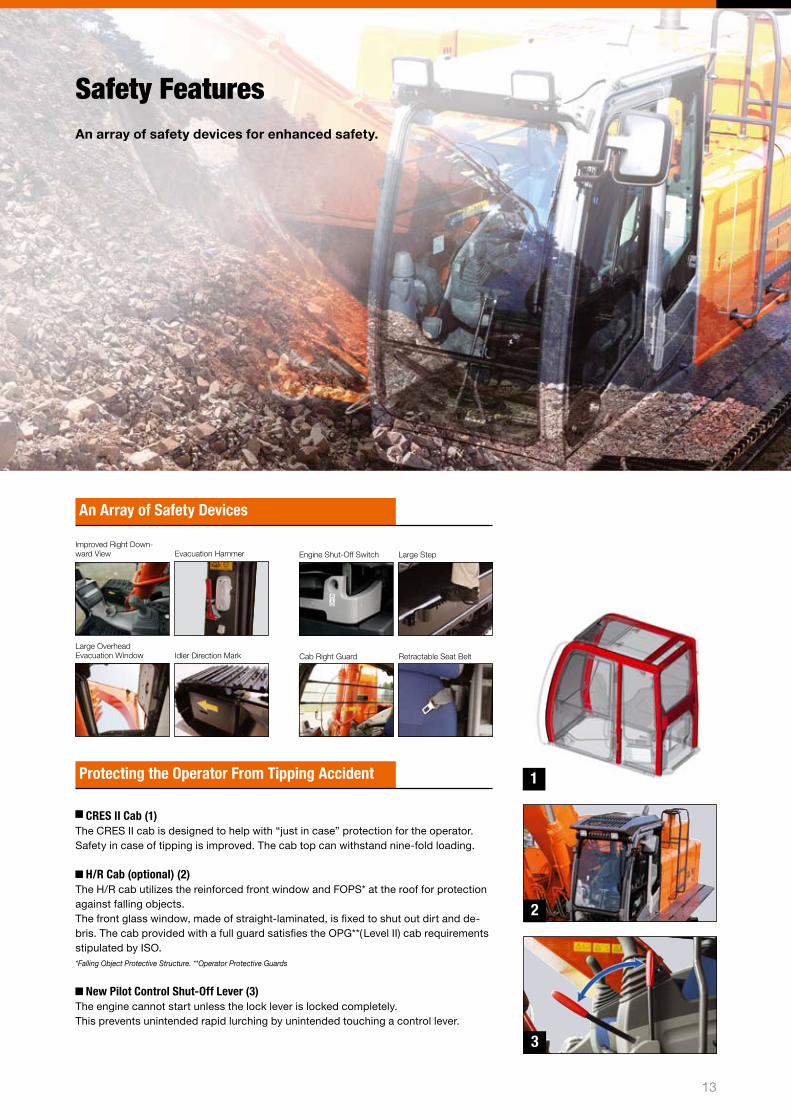
Safety Features An array of safety devices for enhanced safety.
CRES II Cab (1)The CRES II cab is designed to help with “just in case” protection for the operator. Safety in case of tipping is improved. The cab top can withstand nine-fold loading.
H/R Cab (optional) (2)The H/R cab utilizes the reinforced front window and FOPS* at the roof for protection against falling objects. The front glass window, made of straight-laminated, is fixed to shut out dirt and de-bris. The cab provided with a full guard satisfies the OPG**(Level II) cab requirements stipulated by ISO.*Falling Object Protective Structure. **Operator Protective Guards
New Pilot Control Shut-Off Lever (3)The engine cannot start unless the lock lever is locked completely. This prevents unintended rapid lurching by unintended touching a control lever.
Protecting the Operator From Tipping Accident
Improved Right Down-ward View Evacuation Hammer
Large Overhead Evacuation Window Idler Direction Mark
Engine Shut-Off Switch Large Step
Cab Right Guard Retractable Seat Belt
An Array of Safety Devices
1
2
3

Remote fleet management with e-Service Owner’s SiteReduce maintenance effort and costs for your machine fleet with e-Service Owner’s Site; latest machine information of each of your machines available on-line, in your office.
e-Service Owner’s Site is an on-line fleet management tool offered by HCME to each of its customers. It will present all operational information and location of your machines on a PC in your office, giving you an up to date overview of your machines, allowing for full fleet control. Each machine will regularly send its opera-tional data to a satellite and from there, via a ground station to a Hitachi server. The data collected in the server will then be processed and directed to each customer around the world. Your machine information will be available through a secure in-ternet connection for you and your dealer. This communication chain is operational ��h a day, each day of the year. It will support your job planning, help you maintain your machine and allow for enhanced service and trouble shooting support by your local dealer, all directly contributing to reduce downtime and increase the cost performance of your fleet.
All new ZAXIS-� and ZW machines supplied by HCME will have a satellite com-munication unit installed as standard*, meaning each owner can directly enjoy the benefits of e-Service Owner’s Site. Your local dealer will be able to give you access to e-Service Owner’s Site.
e-Service Owner’s Site features
OperationRemote access to all relevant machine opera-tion information such as daily operating hours and machine fuel level as well as historically cumulated temperatures and pressures.
MaintenanceFor each machine, maintenance history as well as recommended maintenance due is displayed in one view, allowing for accurate and efficient fleet maintenance management.
LocationIn addition to any general GPS function, GIS (Geographical Information System) will not only show the geographical position of each machine with immediate serial number identification, it will also allow for dedicated multiple machine searches using specific operational information as search criteria.
Machine
Offering prompt and adequate service
Customer
* (1) Satellite communication units can not be installed in machines for countries that currently do not have Satellite Communication Services available. At the time of print however, the majority of European countries have Satellite Communication Services available and full European coverage is expected.
(2) Satellite communication basically allows for worldwide coverage. Contact your local dealer for the latest situation on actual satellite communication availability for your country or specific jobsite.
(3) If transmission of the satellite signal is hindered in any way, satellite communication may not be possible.
Enhanced service support from your local dealer
Actual geographical location of each of your machines
Check and monitor each of your machines from your office
Optimizing fleet management
Accurate maintenance planning
Job planning support tool
Swift trouble shooting
Satellite
Internet
Operating information
Information sharing
Quick access to information on remote machines
Hitachi Construction Machinery Group and Dealers
Information Center, Hitachi Construction Machinery
1�
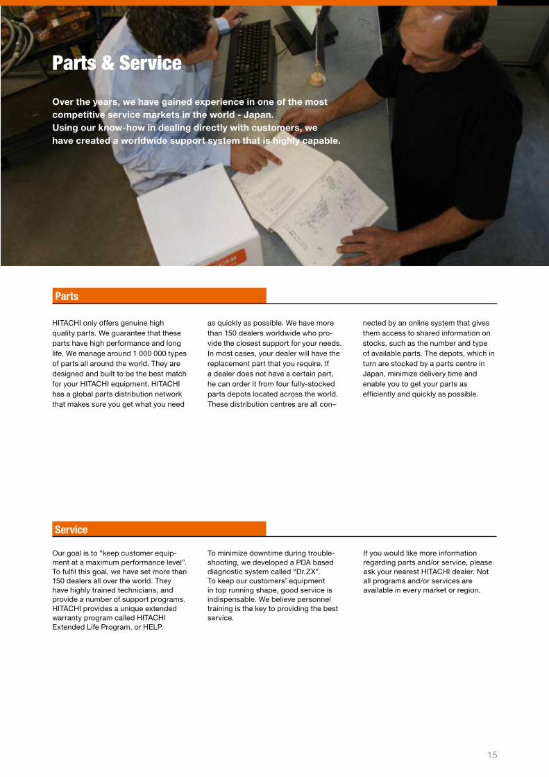
Parts & Service
Over the years, we have gained experience in one of the most competitive service markets in the world - Japan. Using our know-how in dealing directly with customers, we have created a worldwide support system that is highly capable.
HITACHI only offers genuine high quality parts. We guarantee that these parts have high performance and long life. We manage around 1 000 000 types of parts all around the world. They are designed and built to be the best match for your HITACHI equipment. HITACHI has a global parts distribution network that makes sure you get what you need
Parts
Our goal is to “keep customer equip-ment at a maximum performance level”. To fulfil this goal, we have set more than 1�0 dealers all over the world. They have highly trained technicians, and provide a number of support programs.HITACHI provides a unique extended warranty program called HITACHI Extended Life Program, or HELP.
Service
To minimize downtime during trouble-shooting, we developed a PDA based diagnostic system called “Dr.ZX”. To keep our customers’ equipment in top running shape, good service is indispensable. We believe personnel training is the key to providing the best service.
If you would like more information regarding parts and/or service, please ask your nearest HITACHI dealer. Not all programs and/or services are available in every market or region.
as quickly as possible. We have more than 1�0 dealers worldwide who pro-vide the closest support for your needs. In most cases, your dealer will have the replacement part that you require. If a dealer does not have a certain part, he can order it from four fully-stocked parts depots located across the world. These distribution centres are all con–
nected by an online system that gives them access to shared information on stocks, such as the number and type of available parts. The depots, which in turn are stocked by a parts centre in Japan, minimize delivery time and enable you to get your parts as efficiently and quickly as possible.
1�
16
UPPERSTRUCTURE
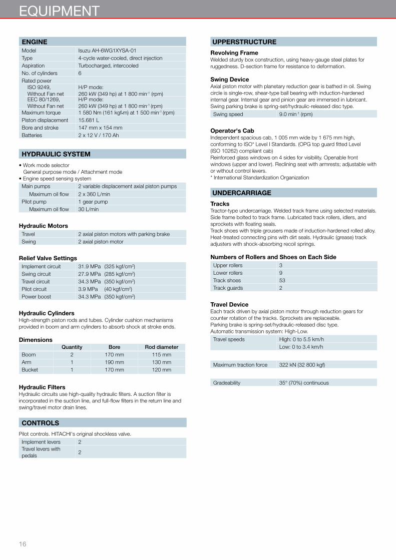
Revolving FrameWelded sturdy box construction, using heavy-gauge steel plates for ruggedness. D-section frame for resistance to deformation.
Swing DeviceAxial piston motor with planetary reduction gear is bathed in oil. Swing circle is single-row, shear-type ball bearing with induction-hardened internal gear. Internal gear and pinion gear are immersed in lubricant. Swing parking brake is spring-set/hydraulic-released disc type.
Swing speed 9.0 min-1 (rpm)
Operator's CabIndependent spacious cab, 1 005 mm wide by 1 675 mm high, conforming to ISO* Level I Standards. (OPG top guard fitted Level (ISO 10262) compliant cab)Reinforced glass windows on 4 sides for visibility. Openable front windows (upper and lower). Reclining seat with armrests; adjustable with or without control levers.* International Standardization Organization
UNDERCARRIAGE
TracksTractor-type undercarriage. Welded track frame using selected materials. Side frame bolted to track frame. Lubricated track rollers, idlers, and sprockets with floating seals.Track shoes with triple grousers made of induction-hardened rolled alloy. Heat-treated connecting pins with dirt seals. Hydraulic (grease) track adjusters with shock-absorbing recoil springs.
Numbers of Rollers and Shoes on Each SideUpper rollers 3Lower rollers 9Track shoes 53 Track guards 2
Travel DeviceEach track driven by axial piston motor through reduction gears for counter rotation of the tracks. Sprockets are replaceable.Parking brake is spring-set/hydraulic-released disc type. Automatic transmission system: High-Low.
Travel speeds High: 0 to 5.5 km/hLow: 0 to 3.4 km/h
Maximum traction force 322 kN (32 800 kgf)
Gradeability 35° (70%) continuous
ENGINEModel Isuzu AH-6WG1XYSA-01Type 4-cycle water-cooled, direct injectionAspiration Turbocharged, intercooledNo. of cylinders 6Rated power
ISO 9249, Without Fan net
H/P mode: 260 kW (349 hp) at 1 800 min-1 (rpm)
EEC 80/1269, Without Fan net
H/P mode: 260 kW (349 hp) at 1 800 min-1 (rpm)
Maximum torque 1 580 Nm (161 kgf•m) at 1 500 min-1 (rpm)Piston displacement 15.681 LBore and stroke 147 mm x 154 mmBatteries 2 x 12 V / 170 Ah
HYDRAULIC SYSTEM
• Work mode selector General purpose mode / Attachment mode • Engine speed sensing systemMain pumps 2 variable displacement axial piston pumps
Maximum oil flow 2 x 360 L/minPilot pump 1 gear pump
Maximum oil flow 30 L/min
Hydraulic MotorsTravel 2 axial piston motors with parking brake Swing 2 axial piston motor
Relief Valve SettingsImplement circuit 31.9 MPa (325 kgf/cm2)Swing circuit 27.9 MPa (285 kgf/cm2)Travel circuit 34.3 MPa (350 kgf/cm2)Pilot circuit 3.9 MPa (40 kgf/cm2)Power boost 34.3 MPa (350 kgf/cm2)
Hydraulic CylindersHigh-strength piston rods and tubes. Cylinder cushion mechanisms provided in boom and arm cylinders to absorb shock at stroke ends.
DimensionsQuantity Bore Rod diameter
Boom 2 170 mm 115 mmArm 1 190 mm 130 mmBucket 1 170 mm 120 mm
Hydraulic FiltersHydraulic circuits use high-quality hydraulic filters. A suction filter is incorporated in the suction line, and full-flow filters in the return line and swing/travel motor drain lines.
CONTROLS
Pilot controls. HITACHI's original shockless valve.
Implement levers 2Travel levers with pedals
2
EQUIPMENT
17
ZAXIS 470LCH
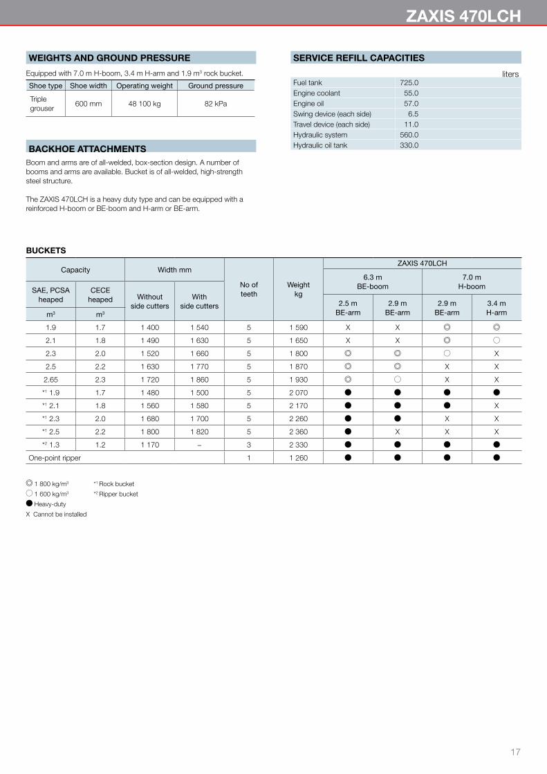
WEIGHTS AND GROUND PRESSURE
Equipped with 7.0 m H-boom, 3.4 m H-arm and 1.9 m3 rock bucket.
Shoe type Shoe width Operating weight Ground pressure
Triplegrouser
600 mm 48 100 kg 82 kPa
BACKHOE ATTACHMENTSBoom and arms are of all-welded, box-section design. A number of booms and arms are available. Bucket is of all-welded, high-strength steel structure.
The ZAXIS 470LCH is a heavy duty type and can be equipped with a reinforced H-boom or BE-boom and H-arm or BE-arm.
SERVICE REFILL CAPACITIES
litersFuel tank 725.0Engine coolant 55.0Engine oil 57.0Swing device (each side) 6.5Travel device (each side) 11.0Hydraulic system 560.0Hydraulic oil tank 330.0
BUCKETS
Capacity Width mm
No ofteeth
Weightkg
ZAXIS 470LCH
6.3 mBE-boom
7.0 mH-boomSAE, PCSA
heapedCECE
heaped Withoutside cutters
Withside cutters 2.5 m
BE-arm2.9 m
BE-arm2.9 m
BE-arm3.4 mH-armm3 m3
1.9 1.7 1 400 1 540 5 1 590 X X
2.1 1.8 1 490 1 630 5 1 650 X X
2.3 2.0 1 520 1 660 5 1 800 X
2.5 2.2 1 630 1 770 5 1 870 X X
2.65 2.3 1 720 1 860 5 1 930 X X
*1 1.9 1.7 1 480 1 500 5 2 070
*1 2.1 1.8 1 560 1 580 5 2 170 X
*1 2.3 2.0 1 680 1 700 5 2 260 X X
*1 2.5 2.2 1 800 1 820 5 2 360 X X X
*2 1.3 1.2 1 170 − 3 2 330
One-point ripper 1 1 260
1 800 kg/m3 *1 Rock bucket
1 600 kg/m3 *2 Ripper bucket
Heavy-duty
X Cannot be installed

18
Unit: mm
ZAXIS 470LCH
Boom length 6.3 m BE-boom 7.0 m H-boom
Arm length 2.5 m BE-arm
2.9 m BE-arm
2.9 m BE-arm
3.4 m H-arm
A Max. digging reach 10 460 10 750 11 330 12 060
A’ Max. digging reach (on ground) 10 210 10 500 11 090 11 840
B Max. digging depth 5 790 6 130 7 200 7 770
B’ Max. digging depth (8’ level) 5 620 5 970 7 000 7 630
C Max. cutting height 10 660 10 790 10 170 11 060
D Max. dumping height 7 320 7 440 7 100 7 650
E Min. swing radius 4 090 3 930 5 020 4 840
F Max. vertical wall 4 260 4 650 4 270 7 100
Bucket digging force* ISO 287 kN 287 kN 287 kN 288 kN
Bucket digging force* SAE : PCSA 258 kN 258 kN 258 kN 250 kN
Arm crowd force* ISO 293 kN 256 kN 256 kN 218 kN
Arm crowd force* SAE : PCSA 286 kN 249 kN 249 kN 209 kN
Equipped bucket SAE : PCSA 2.5 m3 2.5 m3 2.1 m3 1.9 m3
Excluding track shoe lug * At power boost
DIMENSIONS
Unit: mm
ZAXIS 470LCH
A Distance between tumblers 4 470
B Undercarriage length 5 470*1 C Counterweight clearance 1 360
D Rear-end swing radius 3 645
D’ Rear-end length 3 560
E Overall width of upperstructure 3 530
F Overall height of cab 3 450 (3 330)*³*1 G Min. ground clearance 723
H Track gauge: Extended / Retracted 2 890 / 2 390
I Track shoe width G 600
J Undercarriage width : Extended / Retracted 3 490 / 2 990
K Overall width 3 770
L Overall length 11 910*2 M Overall height of boom 3 480
N Track height 1 220
*1 Excluding track shoe lug G: 600 mm Triple grouser shoe*2 Equipped with 7.0 m H-boom and 3.4 m H-arm *³ With CRES II cab
WORKING RANGES
AA'
E
D
FB'
C
B
8'
JH
I
KE
L
AB
DʼD
C
MF
N
G
150%
SPECIFICATIONS
Ground line
* Machine is equiped with H/R cab.
19
ZAXIS 470LCH
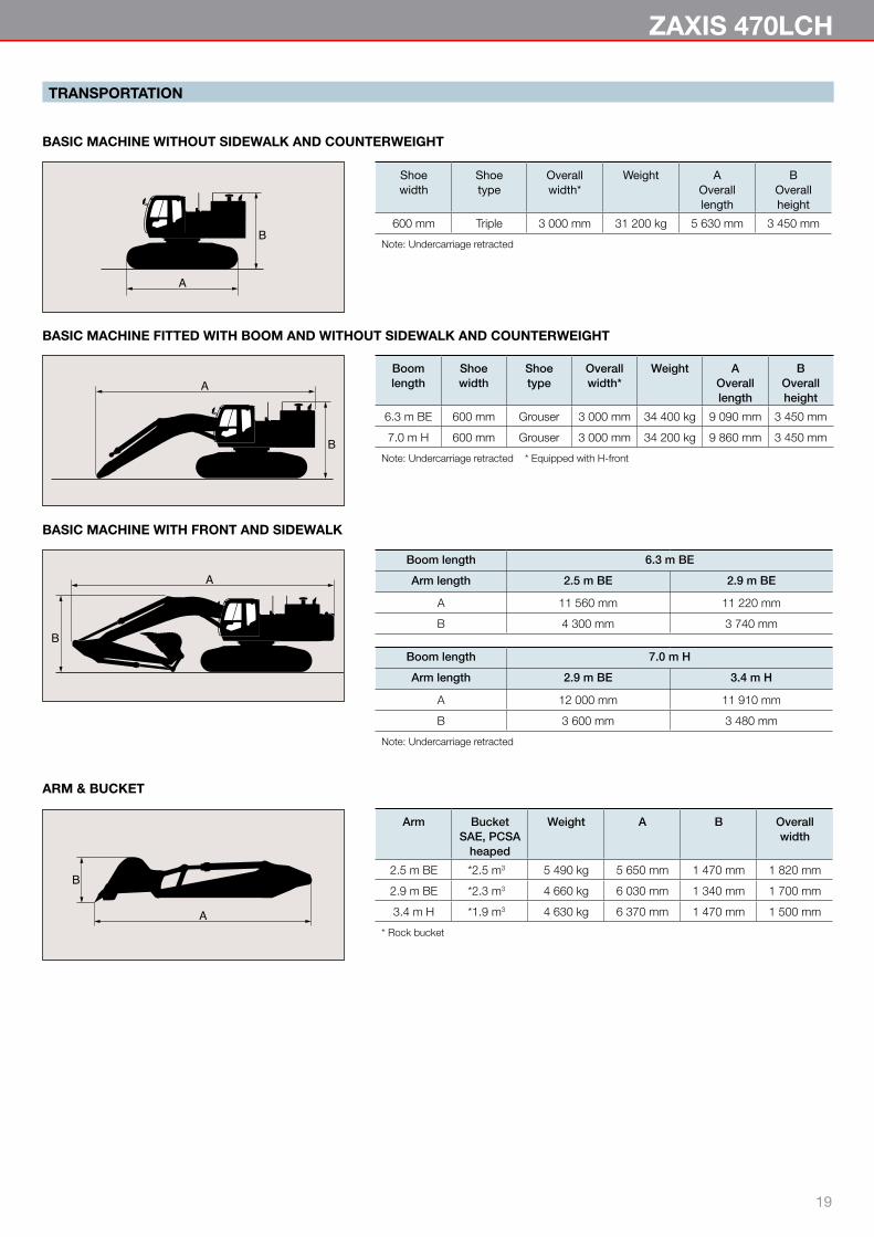
TRANSPORTATION
BASIC MACHINE WITHOUT SIDEWALK AND COUNTERWEIGHT
Shoewidth
Shoetype
Overallwidth*
Weight AOveralllength
BOverallheight
600 mm Triple 3 000 mm 31 200 kg 5 630 mm 3 450 mm
Note: Undercarriage retracted
A
B
A
B
A
B
ARM & BUCKET
Arm BucketSAE, PCSA
heaped
Weight A B Overallwidth
2.5 m BE *2.5 m3 5 490 kg 5 650 mm 1 470 mm 1 820 mm
2.9 m BE *2.3 m3 4 660 kg 6 030 mm 1 340 mm 1 700 mm
3.4 m H *1.9 m3 4 630 kg 6 370 mm 1 470 mm 1 500 mm
* Rock bucket
BASIC MACHINE WITH FRONT AND SIDEWALK
Boom length 6.3 m BE
Arm length 2.5 m BE 2.9 m BE
A 11 560 mm 11 220 mm
B 4 300 mm 3 740 mm
Boom length 7.0 m H
Arm length 2.9 m BE 3.4 m H
A 12 000 mm 11 910 mm
B 3 600 mm 3 480 mm
Note: Undercarriage retracted
BASIC MACHINE FITTED WITH BOOM AND WITHOUT SIDEWALK AND COUNTERWEIGHT
Boomlength
Shoewidth
Shoetype
Overallwidth*
Weight AOveralllength
BOverallheight
6.3 m BE 600 mm Grouser 3 000 mm 34 400 kg 9 090 mm 3 450 mm
7.0 m H 600 mm Grouser 3 000 mm 34 200 kg 9 860 mm 3 450 mm
Note: Undercarriage retracted * Equipped with H-front
A
B

�0
TRANSPORTATION
A
B
BUCKET
Bucket A B
SAE, PCSAheaped
CECEheaped
1.9 m3 1.7 m3 1 960 mm 1 570 mm
2.1 m3 1.8 m3 1 960 mm 1 570 mm
2.3 m3 2.0 m3 1 950 mm 1 660 mm
2.5 m3 2.2 m3 1 950 mm 1 660 mm
2.65 m3 2.3 m3 1 950 mm 1 660 mm
*11.9 m3 1.7 m3 2 030 mm 1 480 mm
*12.1 m3 1.8 m3 1 950 mm 1 650 mm
*12.3 m3 2.2 m3 1 950 mm 1 650 mm
*21.3 m3 1.2 m3 2 150 mm 1 590 mm
*1 Rock bucket *2 Ripper bucket
TRANSPORTATION
COUNTERWEIGHT 9 150 kg SIDEWALK 44 kg SIDEWALK 30 kg
2 960 mm
710
mm
2 340 mm
515
mm
700 mm
515
mm
�1
ZAXIS 470LCH
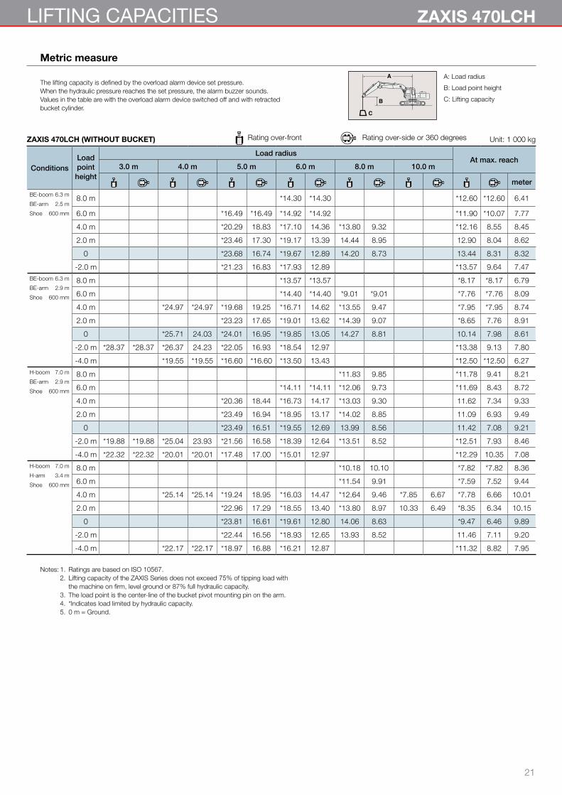
Metric measure
A: Load radius
B: Load point height
C: Lifting capacity
The lifting capacity is defined by the overload alarm device set pressure.When the hydraulic pressure reaches the set pressure, the alarm buzzer sounds.Values in the table are with the overload alarm device switched off and with retractedbucket cylinder.
ZAXIS 470LCH (WITHOUT BUCKET) Rating over-front Rating over-side or 360 degrees Unit: 1 000 kg
ConditionsLoadpointheight
Load radiusAt max. reach
3.0 m 4.0 m 5.0 m 6.0 m 8.0 m 10.0 m
meter
BE-boom 6.3 m
BE-arm 2.5 m
Shoe 600 mm
8.0 m *14.30 *14.30 *12.60 *12.60 6.41
6.0 m *16.49 *16.49 *14.92 *14.92 *11.90 *10.07 7.77
4.0 m *20.29 18.83 *17.10 14.36 *13.80 9.32 *12.16 8.55 8.45
2.0 m *23.46 17.30 *19.17 13.39 14.44 8.95 12.90 8.04 8.62
0 *23.68 16.74 *19.67 12.89 14.20 8.73 13.44 8.31 8.32
-2.0 m *21.23 16.83 *17.93 12.89 *13.57 9.64 7.47BE-boom 6.3 m
BE-arm 2.9 m
Shoe 600 mm
8.0 m *13.57 *13.57 *8.17 *8.17 6.79
6.0 m *14.40 *14.40 *9.01 *9.01 *7.76 *7.76 8.09
4.0 m *24.97 *24.97 *19.68 19.25 *16.71 14.62 *13.55 9.47 *7.95 *7.95 8.74
2.0 m *23.23 17.65 *19.01 13.62 *14.39 9.07 *8.65 7.76 8.91
0 *25.71 24.03 *24.01 16.95 *19.85 13.05 14.27 8.81 10.14 7.98 8.61
-2.0 m *28.37 *28.37 *26.37 24.23 *22.05 16.93 *18.54 12.97 *13.38 9.13 7.80
-4.0 m *19.55 *19.55 *16.60 *16.60 *13.50 13.43 *12.50 *12.50 6.27H-boom 7.0 m
BE-arm 2.9 m
Shoe 600 mm
8.0 m *11.83 9.85 *11.78 9.41 8.21
6.0 m *14.11 *14.11 *12.06 9.73 *11.69 8.43 8.72
4.0 m *20.36 18.44 *16.73 14.17 *13.03 9.30 11.62 7.34 9.33
2.0 m *23.49 16.94 *18.95 13.17 *14.02 8.85 11.09 6.93 9.49
0 *23.49 16.51 *19.55 12.69 13.99 8.56 11.42 7.08 9.21
-2.0 m *19.88 *19.88 *25.04 23.93 *21.56 16.58 *18.39 12.64 *13.51 8.52 *12.51 7.93 8.46
-4.0 m *22.32 *22.32 *20.01 *20.01 *17.48 17.00 *15.01 12.97 *12.29 10.35 7.08H-boom 7.0 m
H-arm 3.4 m
Shoe 600 mm
8.0 m *10.18 10.10 *7.82 *7.82 8.36
6.0 m *11.54 9.91 *7.59 7.52 9.44
4.0 m *25.14 *25.14 *19.24 18.95 *16.03 14.47 *12.64 9.46 *7.85 6.67 *7.78 6.66 10.01
2.0 m *22.96 17.29 *18.55 13.40 *13.80 8.97 10.33 6.49 *8.35 6.34 10.15
0 *23.81 16.61 *19.61 12.80 14.06 8.63 *9.47 6.46 9.89
-2.0 m *22.44 16.56 *18.93 12.65 13.93 8.52 11.46 7.11 9.20
-4.0 m *22.17 *22.17 *18.97 16.88 *16.21 12.87 *11.32 8.82 7.95
Notes: 1. Ratings are based on ISO 10567. 2. Lifting capacity of the ZAXIS Series does not exceed 75% of tipping load with the machine on firm, level ground or 87% full hydraulic capacity. 3. The load point is the center-line of the bucket pivot mounting pin on the arm. 4. *Indicates load limited by hydraulic capacity. 5. 0 m = Ground.
LIFTING CAPACITIES
��
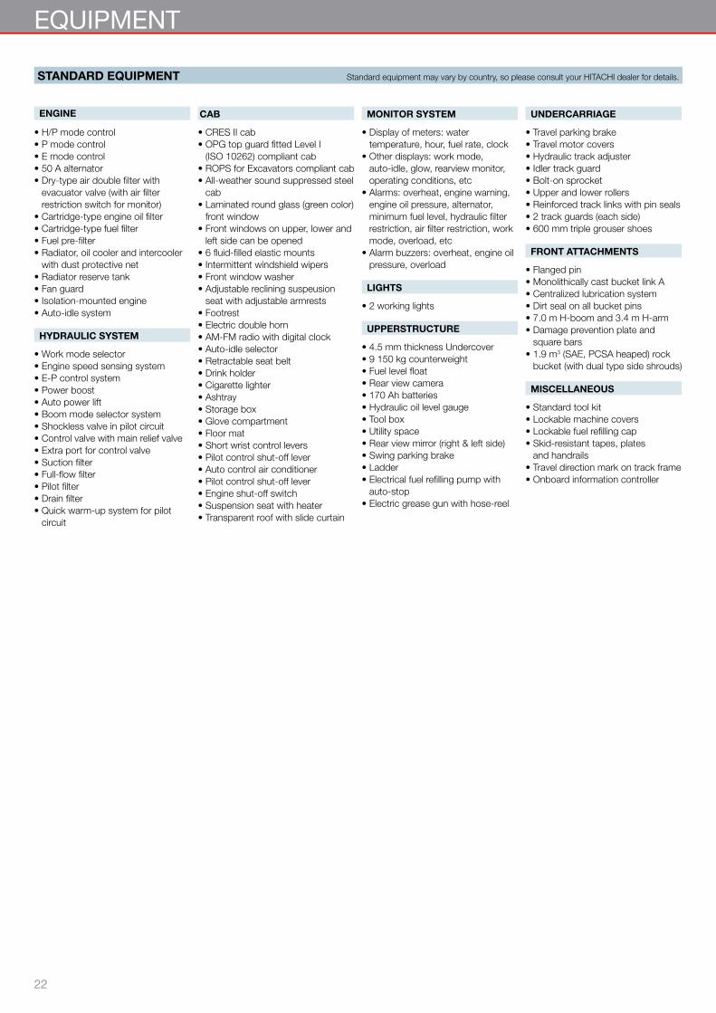
EQUIPMENT
ENGINE
• H/P mode control• P mode control• E mode control• 50 A alternator• Dry-type air double filter with
evacuator valve (with air filter restriction switch for monitor)
• Cartridge-type engine oil filter• Cartridge-type fuel filter• Fuel pre-filter• Radiator, oil cooler and intercooler
with dust protective net• Radiator reserve tank• Fan guard• Isolation-mounted engine• Auto-idle system
HYDRAULIC SYSTEM
• Work mode selector• Engine speed sensing system• E-P control system• Power boost• Auto power lift• Boom mode selector system• Shockless valve in pilot circuit• Control valve with main relief valve• Extra port for control valve• Suction filter• Full-flow filter• Pilot filter• Drain filter• Quick warm-up system for pilot
circuit
CAB
• CRES II cab• OPG top guard fitted Level I
(ISO 10262) compliant cab• ROPS for Excavators compliant cab• All-weather sound suppressed steel
cab• Laminated round glass (green color)
front window• Front windows on upper, lower and
left side can be opened• 6 fluid-filled elastic mounts• Intermittent windshield wipers• Front window washer• Adjustable reclining suspeusion
seat with adjustable armrests• Footrest• Electric double horn• AM-FM radio with digital clock• Auto-idle selector• Retractable seat belt• Drink holder• Cigarette lighter• Ashtray• Storage box• Glove compartment• Floor mat• Short wrist control levers• Pilot control shut-off lever• Auto control air conditioner• Pilot control shut-off lever• Engine shut-off switch• Suspension seat with heater• Transparent roof with slide curtain
MONITOR SYSTEM
• Display of meters: water temperature, hour, fuel rate, clock
• Other displays: work mode, auto-idle, glow, rearview monitor, operating conditions, etc
• Alarms: overheat, engine warning, engine oil pressure, alternator, minimum fuel level, hydraulic filter restriction, air filter restriction, work mode, overload, etc
• Alarm buzzers: overheat, engine oil pressure, overload
LIGHTS
• 2 working lights
UPPERSTRUCTURE
• 4.5 mm thickness Undercover• 9 150 kg counterweight• Fuel level float• Rear view camera• 170 Ah batteries• Hydraulic oil level gauge• Tool box• Utility space• Rear view mirror (right & left side)• Swing parking brake• Ladder• Electrical fuel refilling pump with
auto-stop• Electric grease gun with hose-reel
UNDERCARRIAGE
• Travel parking brake• Travel motor covers• Hydraulic track adjuster• Idler track guard• Bolt-on sprocket• Upper and lower rollers• Reinforced track links with pin seals• 2 track guards (each side)• 600 mm triple grouser shoes
FRONT ATTACHMENTS
• Flanged pin• Monolithically cast bucket link A• Centralized lubrication system• Dirt seal on all bucket pins• 7.0 m H-boom and 3.4 m H-arm• Damage prevention plate and
square bars• 1.9 m3 (SAE, PCSA heaped) rock
bucket (with dual type side shrouds)
MISCELLANEOUS
• Standard tool kit• Lockable machine covers• Lockable fuel refilling cap• Skid-resistant tapes, plates
and handrails• Travel direction mark on track frame• Onboard information controller
STANDARD EQUIPMENT Standard equipment may vary by country, so please consult your HITACHI dealer for details.

��
ZAXIS 470LCH
• Hose rupture valves• Swing motion alarm device with
lamps• Travel motion alarm device • Biodegradable oil• Extinguisher• Pre cleaner
• 2 cab lights (for CRES II cab)• Rain guard for cab• Headguard• Attachment basic piping• Accessories for breaker• Accessories for breaker & crusher• Accessories for 2 speed selector
• Sun visor• 12 V power source• Additional fuse box• Overload alarm• Front glass lower guard• Front glass upper guard• H/R cab (with 2 cab lights)
• Air suspension seat with heater• Additional working light (for boom)• Track undercover• Full track guard• 6.3 m BE-boom• 2.5 m BE-arm• 2.9 m BE-arm
OPTIONAL EQUIPMENT Optional equipment may vary by country, so please consult your HITACHI dealer for details.

KS-EN013EUPHitachi Construction Machinerywww.hcme.com
These specifications are subject to change without notice.Illustrations and photos show the standard models, and may or may not include optional equipment, accessories, and all standard equipment with some differences in colour and features.Before use, read and understand the Operator’s Manual for proper operation.
HYDRAULIC EXCAVATOR