HYDRAULIC FILTRATION
156
HYDRAULIC FILTRATION PRODUCTS TO PERFORM PASSION HIGH PRESSURE FILTERS
Transcript of HYDRAULIC FILTRATION

HYDRAULIC FILTRATIONPRODUCTS
TO PERFORMPASSION
HIGH PRESSURE FILTERS


1
A WORLDWIDE LEADER IN THE FIELD OF HYDRAULIC FILTRATION EQUIPMENT.
Our company started life in 1964, when Bruno Pasotto decided to attempt to cater for the requests of a market still to be fully explored, with the study, design, development, production and marketing of a vast range of fi lters for hydraulic equipment, capable of satisfying the needs of manufacturers in all sectors.The quality of our products, our extreme competitiveness compared with major international producers and our constant activities of research, design and development has made us a worldwide leader in the fi eld of hydraulic circuit fi ltering.Present for over 50 years in the market, we have played a truly decisive role in defi ning our sector, and by now we are a group capable of controlling our entire chain of production, monitoring all manufacturing processes to guarantee superior quality standards and to provide concrete solutions for the rapidly evolving needs of customers and the market.

Our customer-oriented philosophy, which enables us to satisfy all customer requests rapidly and with personalized products, makes us a dynamic and fl exible enterprise.The possibility of constantly controlling and monitoring the entire production process is essential to allow us to guarantee the quality of our products.
Our work is based on a skillful interaction between advanced technology and fi ne workmanship, customizing products according to specifi c market requests, focusing strongly on innovation and quality, and following every step in the manufacturing of both standard and special products, fully respecting customer expectations.
Introduction 2
LEADERMARKET

USA
CANADAUNITED KINGDOM
FRANCE
ITALY
GERMANY
INDIA
RUSSIA
P.R. CHINA
WORLDWIDE PRESENCE
8The Group boasts business branches
Our foreign Branches enable us to offer a diversified range of products that allow us to successfully face the aggressive challenge of international competition, and also to maintain a stable presence at a local level.
Introduction3

Introduction 4
TECHNOLOGY
Our constant quest for excellence in quality and technological innovation allows us to offer only the best solutions and services for applications in many fields, including general industry, test rigs, l u b r i c a t i o n , h e a v y e ng i n e e r i n g, r e n ewab l e energ ies, nava l engineering, offshore engineering, aviation systems, emerging technologies and mobile plant (i.e. tractors, excavators, concrete pumps, platforms).

Introduction5
AND PRODUCTION
Our high level of technological expertise means we can rely entirely on our own resources, without resorting to external providers. This in turn enables us to satisfy a growing number of customer requests, also exploiting our constantly updated range of machines and equ ipmen t , f ea tu r i ng fu l ly-automated workstations capable of 24-hour production.

Flow rates up to 3000 l/min
Pressure up to 20 bar
Mounting:- In-Line- Tank top- In single and duplex designs
Flow rates up to 300 l/min
Pressure up to 80 bar
Mounting:- In-Line- Tank top
Flow rates up to 875 l/min
Mounting:- Tank immersed- In-Line- In tank with shut off valve- In tank with fl ooded suction
Flow rates up to 750 l/min
Pressure from 110 bar up to 560 bar
Mounting:- In-Line- Manifold- In single and duplex designs
Flow rates up to 3000 l/min
Pressure up to 80 bar
Mounting:- In-Line- Parallel manifold version- In single and duplex designs
LOW & MEDIUM PRESSURE FILTERS
HIGH PRESSURE FILTERS
SPIN-ON FILTERS
Flow rates up to 365 l/min
Pressure up to 35 bar
Mounting:- In-Line- Tank top
SUCTION FILTERS
RETURN FILTERS
RETURN /SUCTIONFILTERS
Introduction 6

Flow rates up to 125 l/min
Pressure from 320 bar up to 1000 bar
Mounting:- In-Line- Manifold- In single and duplex designs
Flow rates from 15 l/min up to 200 l/min
MOBILE FILTRATION UNITS
- Oil fi ller and air breather plugs- Optical and electrical level gauges- Pressure gauge valve selectors- Pipe fi xing brackets- Pressure gauges
POWER TRANSMISSIONPRODUCTS
TANKACCESSORIES
CONTAMINATION MONITORING PRODUCTS
STAINLESS STEEL HIGH PRESSURE FILTERS
- Aluminium bell-housings for motors from 0.12 kW to 400 kW- Couplings in Aluminium Cast Iron - Steel- Damping rings- Foot bracket- Aluminium tanks- Cleaning covers
- Online, in-line particle counters- Off-line bottle sampling products- Fully calibrated using relevant ISO standards- A wide range of variants to support fl uid types and communication protocols
PRODUCT RANGEMP Filtri can offer a vast and articulated range of products for the global market, suitable for all industrial sectors using hydraulic equipment.
This includes filters (suction, return, return/suction, spin-on, pressure, stainless steel pressure) and structural components (motor/pump bell-housings, transmission couplings, damping rings, foot brackets, aluminium tanks, cleaning covers).
We can provide all the skills and solutions required by the modern hydraulics industry to monitor contamination levels and other fl uid conditions.
Mobile fi ltration units and a full range of accessories allow us to supply everything necessary for a complete service in the hydraulic circuits.
Introduction7

COMPANY
PRODUCT RANGE
CONTAMINATION MANAGEMENT
FILTER SIZING
CORRECTIVE FACTOR
INTRODUCTION
1
6
11
22
24
page1
STR & MPA - MPM
SF2 250 - 350
SF2 500
CLOGGING INDICATORS
Submerged suction filter, with bypass or magnetic filter
Semi-submerged positive head suction filter, low flow rate
Semi-submerged positive head suction filter, high flow rate
1000 264
160 42
700 185
l/min gpmSUCTION FILTERS
31
39
47
57
page
up to Qmax
28
psi
MPFX
MPLX
MPTX
MFBX
MPF
MPT
MFB
MPH
MPI
FRI
RF2
CLOGGING INDICATORS
ACCESSORIES
Tank top semi-immersed filter, standard filter element disassembly
Tank top semi-immersed filter, standard filter element disassembly
Tank top semi-immersed filter, easy filter element disassembly
Bowl assembly
Tank top semi-immersed filter, standard filter element disassembly
Tank top semi-immersed filter, easy filter element disassembly
Bowl assembly
Tank top semi-immersed filter, standard filter element disassembly
Tank top semi-immersed filter, standard filter element disassembly
Tank top semi-immersed filter, easy filter element disassembly, it can be used also as in-line filter
Semi-immersed under-head filter, easy filter element disassembly
900 238
1800 476
300 79
700 185
900 238
300 79
700 185
3500 925
3500 925
2500 660
615 162
8 116
10 145
8 116
8 116
8 116
8 116
8 116
10 145
10 145
20 290
20 290
l/min gpmRETURN FILTERS
63
91
99
117
125
153
171
179
203
215
231
238
248
page
up to Pmax up to Qmax
60 bar
psi
MRSX
LMP 124 MULTIPORT
CLOGGING INDICATORS
Unique TANK TOP filter for mobile machinery, with combined filtration on
return and suction to the inlet at the hydrostatic transmissions in closed circuit
Unique IN-LINE filter for mobile machinery, with combined filtration on return
and suction to the inlet at the hydrostatic transmissions in closed circuit
250 66
120 32
10 145
80 1160
l/min gpmRETURN / SUCTION FILTERS
253
265
273
page
up to Pmax up to Qmax
250 bar
psi
MPS
MSH
CLOGGING INDICATORS
Low pressure filter, available with single cartridge (CS) for in-line or flange
mounting or with two cartridge on the same axis on the opposite sides
In-line low and medium pressure filter available with single cartridge (CH)
365 96
195 52
12 174
35 508
l/min gpmSPIN-ON FILTERS
289
305
311
page
up to Pmax up to Qmax
286 bar
HYDRAULIC FILTRATION PRODUCTS
Introduction 8

INDEX
QUICK REFERENCE GUIDE
CLOGGING INDICATORS
649
page646
psi l/min gpm
up to Qmax
FZP
FZH
FZX
FZM
FZB
FZD
CLOGGING INDICATORS
In-line pressure filter with threaded mount
In-line pressure filter with threaded mount for higher pressure
In-line pressure filter with threaded mount up to 1000 bar
Manifold top mounting
Manifold side mounting
Duplex pressure filter for continuous operation requirements
420 6092
700 10153
1000 14504
320 4641
320 4641
350 5076
STAINLESS STEEL HIGH PRESSURE FILTERS
587
597
607
615
623
631
641
page
up to Pmax
584 bar
160 42
80 21
10 3
70 18
70 18
60 16
up to Pmax up to Qmax
LMP 110 - 120 - 123 MULTIPORT
LMP 210 - 211
LMP 400 - 401 & 430 - 431
LMP 950 - 951
LMP 952 - 953 - 954
LMD 211
LMD 400 - 401 & 431
LMD 951
In-line filter with Multiport design for multiple choice connection
In-line low & medium pressure filter, low flow rate
In-line low & medium pressure filter, high flow rate
In-line filter, available with 2 and up to 6 different heads
In-line low pressure filter specifically designed to be mounted in series
In-line duplex medium pressure filter
In-line duplex low pressure filter
In-line duplex filter, available with 2 up to 6 different heads
175 46
365 96
780 206
2400 634
4500 1189
200 53
600 159
1200 317
80 1160
60 870
60 870
30 435
25 363
60 870
16 232
16 232
LDP - LDD
LMP 900 - 901
LMP 902 - 903
Filter elements designed according to DIN 24550
In-line and duplex medium pressure filter
In-line low pressure filter
In-line filter specifically designed to be mounted in series
360 95
2000 528
3000 793
60 870
30 435
20 290
psi l/min gpmLOW & MEDIUM PRESSURE FILTERS
325
341
351
363
371
383
391
407
415
417
427
435
CLOGGING INDICATORS
ACCESSORIES
444
450
page322 bar
psi
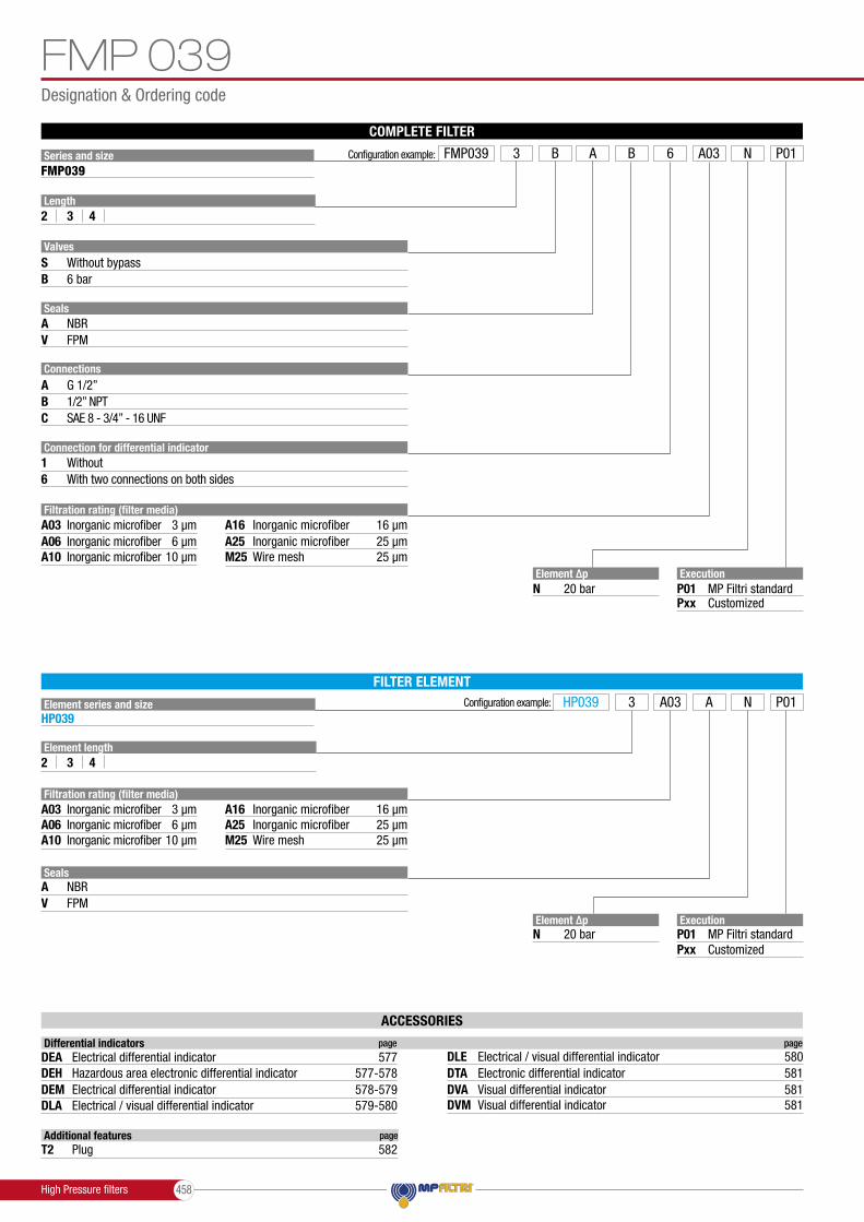
FMP 039
FMP
FHP
FMM
HPB
FHA 051
FHM
FHB
FHF 325
FHD
CLOGGING INDICATORS
Filter high pressure, low flow rate applications
Filter high pressure, high flow rate applications
Typical high pressure filter for mobile applications, high flow rate
Typical high pressure filter for mobile applications, low flow rate
Pressure filter kits for integration in control manifolds
Filter optimized for use in high pressure operating systems, low flow rate
High pressure filter with intermediate manifold construction
High pressure for block mounting
In-line manifold top mounting
In-line duplex high pressure filter
80 21
500 132
630 166
300 79
300 79
150 40
400 106
485 128
550 145
250 66
110 1595
320 4641
420 6092
420 6092
420 6092
560 8122
320 4641
320 4641
350 5076
350 5076
l/min gpmHIGH PRESSURE FILTERS
455
463
475
493
503
513
521
539
553
563
576
page
up to Pmax up to Qmax
452 bar
Introduction9

THE CORRECT FILTER SIZING HAVE TO BE BASED ON THE TOTAL PRESSURE DROP DEPENDING BY THE APPLICATION. FOR EXAMPLE, THE MAXIMUM TOTAL PRESSURE DROP ALLOWED BY A NEW AND CLEAN RETURN FILTER HAVE TO BE IN THE RANGE 0.4 - 0.6 bar / 5.80 - 8.70 psi.
The pressure drop calculation is performed by adding together the value of the housing with the value of the filter element. The pressure drop ∆pc of the housing is proportional to the fluid density (kg/dm3 / lb/ft3).The filter element pressure drop ∆pe is proportional to its viscosity (mm2/s / SUS), the corrective factor Y have to be used in case of an oil viscosity different than 30 mm2/s (cSt) / 150 SUS.
Generic filter calculation exampleApplication data:Tank top return filterPressure Pmax = 10 barFlow rate Q = 120 l/minViscosity V2 = 46 mm2/s (cSt)Oil density = 0.86 kg/dm3
Required filtration efficiency = 25 μm with absolute filtrationWith bypass valve and G 1 1/4” inlet connection
Filter housings ∆p pressure drop.The curves are plotted using mineral oil with density of 0.86 kg/dm3 in compliance with ISO 3968. ∆p varies proportionally with density.
Filter element
Absolute filtration Nominal filtration
Type A03 A16A06 A25A10 P10 P25M25M60M90
H Series N Series
123
MF 020
74.0029.2022.00
50.0824.1219.00
20.008.006.56
16.007.225.33
6.433.331.68
5.512.851.44
4.402.001.30
9.005.004.33
1MF 030MFX 030 74.00 50.08 20.00 16.00 6.43 5.51 3.409.00
1234
MF 100MFX 100
28.2017.3310.256.10
24.4012.509.005.40
8.676.863.652.30
8.175.703.332.20
4.623.051.631.19
3.962.471.320.96
1.251.100.960.82
6.884.002.502.00
Return filters
Sizing data for single filter element, head at top∆pc = Filter housing pressure drop [bar / psi]∆pe = Filter element pressure drop [bar / psi]Y = Corrective factor Y (see correspondent table), depending on the filter type, on the filter element size, on the filter element length and on the filter mediaQ = flow rate (l/min - gpm)V1 reference oil viscosity = 30 mm2/s (cSt) /150 SUSV2 = operating oil viscosity in mm2/s (cSt) / SUS
Filter element pressure drop calculation with an oil viscosity different than 30 mm2/s (cSt) / 150 SUS
International system:∆pe = Y : 1000 x Q x (V2:V1)
Imperial system: ∆pe = Y : 17.2 x Q x (V2:V1)
∆p Tot. = ∆pc + ∆pe
Verification formula∆p Tot. ≤ ∆p max allowed
FILTER SIZING Calculation
Maximum total pressure drop (∆p max) allowed by a new and clean filter
Suction filtersReturn filtersReturn - Suction filters (*)
High Pressure filtersStainless Steel filters
0.08 - 0.10 bar0.4 - 0.6 bar0.8 - 1.0 bar0.4 - 0.6 bar0.3 - 0.5 bar0.3 - 0.4 bar0.1 - 0.3 bar0.4 - 0.6 bar
1.16 - 1.45 psi5.80 - 8.70 psi 11.60 - 14.50 psi5.80 - 8.70 psi4.35 - 7.25 psi4.35 - 5.80 psi1.45 - 4.35 psi5.80 - 8.7 psi
0.8 - 1.5 bar0.8 - 1.5 bar
11.60 - 21.75 psi11.60 - 21.75 psi
return lineslubrication lines
over-boost
off-line in power systemsoff-line in test benches
Application Range: [ psi ][ bar ]
(*) The suction flow rate should not exceed 30% of the return flow rate
Low & MediumPressure filters
Calculation:∆pc = 0.03 bar / 0.43 psi (see graphic below)
*
0.40
0.30
0.20
0.10
0
MPT 110 - Length 3 - 4
Δp
bar
0 60 120 180 240 300Flow rate l/min
G 1 1/4”
5.8
4.33
2.9
1.45
0
Δp
psi
0 16 32 48 64 80
Flow rate gpm
∆pe = (2.00 : 1000) x 120 x (46 : 30) = 0.37 bar∆pe = (2.00 : 17.2) x 32 x (216 : 150) = 5.36 psi
∆p Tot. = 0.03 + 0.37 = 0.4 bar∆p Tot. = 0.43 + 5.36 = 5.79 psi
The selection is correct because the total pressure drop value is inside the admissible range for top tank return filters.In case the allowed max total pressure drop is not verified, it is necessary to repeat the calculation changing the filter length/size.

FILTER SIZINGCorrective factor
123
HF 3253.652.031.84
2.951.731.42
2.801.611.32
1.801.351.22
0.900.850.80
0.380.360.35
High pressure filtersFilter element
Type
Type
Absolute filtration
Absolute filtration - N Series
Nominal filtration
A03
A03
A16
A16
A06
A06
A25
A25
A10
A10
M25
M25
N - R Series N Series
1234
HP 011
----
332.71220.28123.2477.76
250.07165.5692.6858.52
184.3274.0841.4828.37
152.3659.1333.0822.67
128.3637.0520.7216.17
1234
HP 320
10.884.402.752.12
9.733.832.111.77
5.021.751.050.98
3.731.480.870.78
2.540.880.770.55
1.040.710.610.47
234
HP 03970.6636.5726.57
53.2032.2823.27
25.7718.0012.46
20.5713.38
8.80
14.678.005.58
4.902.902.20
123
HP 06558.5042.6020.50
43.4625.6415.88
23.1616.22
8.18
19.6613.88
6.81
10.717.323.91
1.281.110.58
123
HP 13520.3311.146.48
18.8010.16
6.33
9.716.603.38
8.666.383.16
4.782.222.14
2.781.111.01
123
HP 15017.538.606.53
15.918.375.90
7.483.542.93
6.963.382.79
5.943.152.12
1.070.580.49
12345
HP 050
31.7524.2517.3712.127.00
30.3021.2616.2510.75
6.56
13.1611.70
8.906.103.60
12.39.097.185.753.10
7.294.903.633.082.25
1.601.401.251.070.80
12345
HP 500
4.443.372.221.811.33
3.672.771.981.331.15
2.301.781.110.930.77
2.101.681.090.860.68
1.651.240.750.680.48
0.150.100.080.050.04
Corrective factor Y to be used for the filter element pressure drop calculation. The values depend to the filter size and length and to the filter media.Reference oil viscosity 30 mm2/s

Choose fi lter type (MPF, MPT, etc.) in function of the max working pressure and the max fl ow rate
Step 3
TYPICAL FILTER SIZINGSelect “FILTERS”Step 1
Choose fi lter group (Return Filter, Pressure Filter, etc.)Step 2
Push “PROCEED”Step 4
Download PDF Datasheet “Report.aspx” pushing the button “Drawing”
Step 7
Insert all application data to calculate the fi lter size following the sequence: - working pressure- working fl ow rate- working pressure drop- working temperature- fl uid material and fl uid type- fi ltration media- connection type
Step 5
Push “CALCULATE” to have result; in case of any mistake, the system will advice which parameter is out of range to allow to modify/adjust the selection
Step 6
Selection Software

TYPICAL FILTER SIZING

High pressure � lters are used as process � lters to protect individual valves or the entire hydraulic circuit from contamination as per ISO 4406. 9 versions are available with operating pressures range from 110 bar up to 560 bar. A range of products is available to resolve all � ltermounting problems, in the following con� gurations:- In-line, with threaded and � ange mounting- Manifold top mounting- Manifold side mounting- Manifold mounting, to DIN 24340 CETOP R 35 H- Manifold threaded/� ange mounting
in the top extraction � lter cartridge version- Duplex versions for continuous operation requirements
FILTER SIZINGFor the proper corrective factor Y see chapter at page 25
FMP series is speci� cally designed and suitable for:- feed pumps of hydrostatic drives- pressure lubrication- hydraulic systems in the high pressure range
FMM series is optimized for the protection of servo and proportional hydraulics:- in agricultural machinery- in construction machinery- in commercial vehicles
HPB are kits designed for the direct integration into the control block; they can be easily integratedinto the block through a simple cavity.
FHP & FHA series are the typical high-pressure � lters optimized for industrial applications.
FHM series is designed for intermediate plate construction, CETOP design.
FHB series is designed for block mounting; the � lter head can be screwed in from the outside.
FHF series is designed to assemble HF4 � lter elementaccording to SAE J2066.
FHD series is the duplex high pressure � lter; with two independent � lter heads, the � ow can be switched without interruption during operation.
The range includes a complete set of valves:- Bypass valve- Check valve- Bypass + check valve- Reverse-� ow valve- Reverse-� ow + bypass valve
High Pressure � lters 452

High pressure fi lters
FMP 039FMPFHPFMMHPBFHA 051
page 455463475493503513
FHMFHBFHF 325FHDINDICATORS
page 521539553563576
High Pressure fi lters453

High Pressure fi lters 454

FMP 039 seriesMaximum working pressure up to 11 MPa (110 bar) - Flow rate up to 80 l/min
High Pressure fi lters
High Pressure fi lters455

GENERAL INFORMATIONFMP 039
High Pressure fi lters- Head: Anodized aluminium- Housing: Anodized aluminium- Bypass valve: Steel
Filter housing materials
- Test pressure: 17 MPa (170 bar)- Burst pressure: 33 MPa (330 bar)- Pulse pressure fatigue test: 1 000 000 cycles with pressure from 0 to 11 MPa (110 bar)
Pressure
From -25 °C to +110 °CTemperature
- Opening pressure 600 kPa (6 bar) ±10%- Other opening pressures on request.
Bypass valve
- Microfi bre fi lter elements - series N: 20 bar- Wire mesh fi lter elements - series N: 20 bar- Fluid fl ow through the fi lter element from OUT to IN.
∆p element type
- Standard NBR series A- Optional FPM series V
Seals
FMP 039 fi lters are provided for vertical mounting
Note
In-line Inlet/OutletConnections
Special connections on request
Executions
without indicator connection double indicator connection (A - B) A:Closure cap with standard T2 steel.The position of the capis reversible.
B:Standard closure cap with plastic thread protection.
If necessary, a second T2 plug is available, see ordering information.
Execution 1: Execution 6
Weights [kg] and volumes [dm3]
0.60 0.70 0.802 3 4Length Length
Weights [kg]
FMP 039 0.19 0.26 0.342 3 4
Volumes [dm3] Filter series
In-lineMaximum working pressure up to 11 MPa (110 bar)Flow rate up to 80 l/min
FMP039 is a range of versatile medium pressure fi lter for transmission, protection of sensitive components in medium pressure hydraulic systems and fi ltration of the coolant into the machine tools.They are directly connected to the lines of the system through the hydraulic fi ttings.
Available features:- 1/2” female threaded connections, for a maximum fl ow rate of 80 l/min- Fine fi ltration rating, to get a good cleanliness level into the system- Bypass valve, to relieve excessive pressure drop across the fi lter media- Low collapse filter element “N”, for use with filters provided with bypass valve- Visual, electrical and electronic differential clogging indicators
Common applications:Delivery lines, in any medium pressure industrial equipment or mobile machines
Description Technical data
A
B
High Pressure fi lters 456

GENERAL INFORMATION FMP 039
Pressure drop
The curves are plotted using mineral oil with density of 0.86 kg/dm3 in compliance with ISO 3968. ∆p varies proportionally with density.
Filter housings ∆p pressure drop
ValvesBypass valve pressure drop
15
10
5
00 20 40 60 80 100
1.50
1.00
0.50
0.000 20 40 60 80 100
FMP 039
FMP 039
ValvesBypass valve pressure drop
15
10
5
00 20 40 60 80 100
1.50
1.00
0.50
0.000 20 40 60 80 100
FMP 039
FMP 039Bypass valve pressure drop
Flow rate l/min
with bypass
without bypass
Flow rate l/min
∆p b
ar∆p
bar
Style S Style B Filter series
FMP 039
OUT
D.I.
IN
OUT
D.I.
IN
• •
234
FMP 039
Filter element design - N SeriesLengthFilter series
Maximum flow rate for a complete pressure filter with a pressure drop ∆p = 1.5 bar.The reference fluid has a kinematic viscosity of 30 mm2/s (cSt) and a density of 0.86 kg/dm3.For different pressure drop or fluid viscosity we recommend to use our selection software available on www.mpfiltri.com.You can also calculate the right size using the formulas present on the FILTER SIZING paragraph at the beginning of the full catalogue or at the beginning of the filter family brochure.Please, contact our Sales Department for further additional information.
Hydraulic symbols
A03 A06 A10 A16 A25 M25 20 26 45 52 61 97 35 39 56 64 76 98 44 48 66 71 82 92
FILTER ASSEMBLY SIZINGFlow rates [l/min]
High Pressure filters457
Designation & Ordering code
ACCESSORIES
FILTER ELEMENT
Element series and sizeHP039
Configuration example:
ExecutionP01Pxx
MP Filtri standardCustomized
HP039 A3 NA03 P01
Filtration rating (filter media)A03
M25
M25
A10A06
A16
A16
A25
A25
Inorganic microfiber
Wire mesh
Wire mesh
3 µm
25 µm
25 µm
Inorganic microfiber 10 µmInorganic microfiber 6 µm
Inorganic microfiber
Inorganic microfiber
16 µm
16 µm
Inorganic microfiber
Inorganic microfiber
25 µm
25 µm
SealsAV
NBRFPM
Element length2 3 4
Element ∆pN 20 bar
COMPLETE FILTER
Series and size Configuration example:
Execution Element ∆pP01NPxx
MP Filtri standard20 barCustomized
FMP039 A3 6 NBB A03 P01FMP039
Filtration rating (filter media)
Connection for differential indicator
A03
1
A10A06
6
Inorganic microfiber
Without
3 µm
Inorganic microfiber 10 µmInorganic microfiber
With two connections on both sides
6 µm
SealsA
SB
VNBR
Without bypass6 bar
FPM
Length
Valves
2 3 4
ConnectionsA
CB
G 1/2”
SAE 8 - 3/4” - 16 UNF1/2” NPT
Additional features page
T2 Plug 582
Differential indicators page page
DEA DLEElectrical differential indicator 577 Electrical / visual differential indicator 580
DLADEM
Electrical / visual differential indicator 579-580Electrical differential indicator 578-579 DVA
DTA
DVMVisual differential indicator 581Electronic differential indicator
Visual differential indicator
581
581
DEH Hazardous area electronic differential indicator 577-578
FMP 039
High Pressure filters 458

Dimensions
FMP039
16.5
Ø57
Filter length
H[mm]
234
151194238
Connections R
AB - C
M61/4” UNC
OUT
Version 1 Version 6
IN
Recommendedclearance spacefor maintenance
Connection for differential indicator
T2 plug
Connection for differential indicator
R - depth 6 mmNr. 2 holes
The position of the T2 plug is reversible
FMP 039
High Pressure filters459

Order number for spare parts
SPARE PARTS
4 3e 3d
3a
3b
3c
2
Item:
Filter series
Seal Kit code numberFilterelement NBR FPM
FMP 039 02050509 02050510See
order table
2Q.ty: 1 pc.Q.ty: 1 pc.
(3a ÷ 3e)3
FMP 039
FMP 039
High Pressure fi lters 460

FMP 039
High Pressure filters461

High Pressure fi lters 462

FMP seriesMaximum working pressure up to 32 MPa (320 bar) - Flow rate up to 500 l/min
High Pressure fi lters
High Pressure fi lters463

GENERAL INFORMATIONFMP
- Head: Phosphatized cast iron- Housing: Phosphatized steel- Bypass valve: Brass- Reverse Flow: Steel (only for series FMP 320)- Check valve: Steel
Filter housing materials
- Test pressure: 48 MPa (480 bar)- Burst pressure: 96 MPa (960 bar)- Pulse pressure fatigue test: 1 000 000 cycles with pressure from 0 to 32 MPa (320 bar)
Pressure
From -25 °C to +110 °CTemperature
- Opening pressure 600 kPa (6 bar) ±10%- Other opening pressures on request.
Bypass valve
- Microfi bre fi lter elements - series N-R: 20 bar- Microfi bre fi lter elements - series H-S: 210 bar- Wire mesh fi lter elements - series N: 20 bar- Fluid fl ow through the fi lter element from OUT to IN
∆p element type
- Standard NBR series A- Optional FPM series V
Seals
FMP fi lters are provided for vertical mounting
Note
In-line Inlet/OutletConnections
Weights [kg] and volumes [dm3]
FMP 065FMP 135FMP 320
Volumes [dm3]
0.360.451.03
--
3.35
0.470.781.75
0.841.002.52
1 42 3Weights [kg]
3.265.61
10.95
--
17.85
3.627.21
13.08
4.838.27
15.37
1 42 3 Filter series
High Pressure fi lters
In-lineMaximum working pressure up to 32 MPa (320 bar)Flow rate up to 500 l/min
FMP is a range of versatile high pressure filter for protection of sensitive components in high pressure hydraulic systems in the industrial equipment.They are directly connected to the lines of the system through the hydraulic fi ttings.
Available features:- Female threaded connections up to 1 1/2” and fl anged connections up to 1 1/2”, for a maximum fl ow rate of 475 l/min- Fine fi ltration rating, to get a good cleanliness level into the system- Bypass valve, to relieve excessive pressure drop across the fi lter media- Check valve, to protect the system against reverse fl ow- Low collapse filter element “N”, for use with filters provided with bypass valve- High collapse fi lter element “H”, for use with fi lters not provided with bypass valve- Low collapse fi lter element with external support “R”, for fi lter element protection against the back pressure caused by the check valve in fi lters provided with the bypass valve- High collapse fi lter element with external support “S”, for fi lter element protection against the back pressure caused by the check valve in fi lters not provided with the bypass valve- Visual, electrical and electronic differential clogging indicators
Common applications:Delivery lines, in any high pressure industrial equipment or mobile machines
Description Technical data
Length Length
High Pressure fi lters 464

GENERAL INFORMATION FMPFILTER ASSEMBLY SIZING
Flow rates [l/min]
Hydraulic symbols Filter seriesFMP 065FMP 135FMP 320
Style S - E Style B - C Style T Style D•••
•••
•••
•
••
OUT
D.I.
IN
OUT
D.I.
IN
OUT
D.I.
IN
OUT
D.I.
IN
123
FMP 065
Filter element design - N SeriesLength
1234
FMP 320
123
FMP 135
Maximum flow rate for a complete pressure filter with a pressure drop ∆p = 1.5 bar.The reference fluid has a kinematic viscosity of 30 mm2/s (cSt) and a density of 0.86 kg/dm3.For different pressure drop or fluid viscosity we recommend to use our selection software available on www.mpfiltri.com.You can also calculate the right size using the formulas present on the FILTER SIZING paragraph at the beginning of the full catalogue or at the beginning of the filter family brochure.Please, contact our Sales Department for further additional information.
Filter series A03 A06 A10 A16 A25 M25 23 30 48 54 72 105 31 45 60 65 82 106 52 60 80 84 94 108
69 73 120 129 171 201 110 117 149 152 211 232 151 152 192 195 212 233
130 144 244 296 361 477 267 291 417 438 492 509 348 390 476 493 503 519 389 415 483 502 525 534
High Pressure filters465

GENERAL INFORMATIONFMPPressure drop
The curves are plotted using mineral oil with density of 0.86 kg/dm3 in compliance with ISO 3968. ∆p varies proportionally with density.
Filter housings ∆p pressure drop
Valves
Bypass valve pressure drop
15
10
5
00 18 36 54 72 90
15
10
5
00 12 24 36 48 60
FMP 065
FMP 1354.50
3.00
1.50
0.000 70 140 210 280 350
15
10
5
00 50 100 150 200 250
FMP 320
FMP 320
FMP 320 - Filter housing with check valve
2
1
1 - Reverse flow2 - In filter direction
1.00
0.50
0.000 50 100 150 200 250
1.50
1.00
0.50
0.000 25 50 75 100 125
FMP 065
3/4”
3/4”
1/2”
1.50
1.50
1.00
0.50
0.000 100 200 300 400 500
FMP 135
1”
FMP 320
1 1/2”
1 1/4”
Filter housing with check valve
1 - Reverse flow2 - In filter direction
Bypass valve pressure drop
Valves
Flow rate l/min Flow rate l/min
Check ValveCheck Valve
Check Valve
Flow rate l/min
Flow rate l/min
Flow rate l/min
Flow rate l/min
Flow rate l/min
∆p b
ar
∆p b
ar∆p
bar
∆p b
ar
∆p b
ar∆p
bar
∆p b
ar
High Pressure filters 466

GENERAL INFORMATION FMP
High Pressure filters467

Designation & Ordering code
FMP
COMPLETE FILTER
Series and size Configuration example: FMP065 A3 SG1T M25 P01FMP065 FMP135 FMP320
M25
A16A25
Wire mesh 25 µm
Inorganic microfiber 16 µmInorganic microfiber 25 µm
Filtration rating (filter media)A03
A10A06
Inorganic microfiber 3 µm
Inorganic microfiber 10 µmInorganic microfiber 6 µm
M25
A16A25
Wire mesh 25 µm
Inorganic microfiber 16 µmInorganic microfiber 25 µm
Filtration rating (filter media)A03
A10A06
Inorganic microfiber 3 µm
Inorganic microfiber 10 µmInorganic microfiber 6 µm
SealsA VNBR FPM
S CE TB D
Without bypass With bypass 6 bar, plug on the opposite sideWithout bypass, plug on the opposite side With check valve, without bypassWith bypass 6 bar With check valve, with bypass
Valves
ConnectionsG1
G4G3
G6
F2
F4
G2
G5
F1
F3
G 1/2”
3/4” NPT1/2” NPT
SAE 12 - 1 1/16” - 12 UN
-
-
G 3/4”
SAE 8 - 3/4” - 16 UNF
-
-
G 3/4”
1” NPT3/4” NPT
SAE 16 - 1 5/16” - 12 UN
1” SAE 3000 psi/M
1” SAE 3000 psi/UNC
G 1”
SAE 12 - 1 1/16” - 12 UN
3/4” SAE 3000 psi/M
3/4” SAE 3000 psi/UNC
G 1 1/4”
1 1/2” NPT1 1/4” NPT
SAE 24 - 1 7/8” - 12 UN
1 1/2” SAE 3000 psi/M
1 1/2” SAE 3000 psi/UNC
G 1 1/2”
SAE 20 - 1 5/8” - 12 UN
1 1/4” SAE 3000 psi/M
1 1/4” SAE 3000 psi/UNC
FMP065 - FMP135 - FMP320
FILTER ELEMENT
Element series and sizeHP065 HP135 HP320
Configuration example:
ExecutionP01Pxx
MP Filtri standardCustomized
HP065 A3 SM25 P01
SealsAV
NBRFPM
Element ∆pNRHS
20 bar20 bar
210 bar210 bar
Element length1234
HP320HP135HP065••••••••
••
ExecutionP01P02Pxx
MP Filtri standardMaintenance from the bottom of the housingCustomized
4321•••••
Filter lengthValvesC DB TES•
••
•••
Element ∆pNRHS
20 bar20 bar
210 bar210 bar
Length1234
FMP320FMP135FMP065
FMP065 FMP135 FMP320
••••••••
••
ACCESSORIES
Additional features page
T2 Plug 582
Differential indicators page page
DEA DLEElectrical differential indicator 577 Electrical / visual differential indicator 580
DLADEM
Electrical / visual differential indicator 579-580Electrical differential indicator 578-579 DVA
DTA
DVMVisual differential indicator 581Electronic differential indicator
Visual differential indicator
581
581
DEH Hazardous area electronic differential indicator 577-578
High Pressure filters 468

Dimensions
FMPFMP065 - FMP135 - FMP320
Ø68
FMP065
Filter length
H[mm]
123
169200302
Connections R
G1-G2G3-G4-G5-G6
M85/16” UNCOUT
Valves S - B - T - D Valves E - C
IN
Recommendedclearance spacefor maintenance
Connection for differential indicatorT2 plug not included
R - depth 15 mmNr. 2 holes
Connection for differential indicatorT2 plug not included
Bypass plug
Bypass plug
Ø68
High Pressure filters469

Dimensions
FMP135
FMP
Ø77
Filter length
H[mm]
123
221334409
FMP065 - FMP135 - FMP320
Connections R
G1-G2G3-G4-G5-G6
F1-F2F3-F4
M103/8” UNC
M103/8” UNC
OUT
Valves S - B - T - D Valves E - C
IN
Connection for differential indicatorT2 plug not included
R - depth 10 mmNr. 3 holes
Connection for differential indicatorT2 plug not included
Bypass plug
Bypass plug
High Pressure filters 470

Dimensions
FMP320
FMP
40 40
Ø101
FMP065 - FMP135 - FMP320
Length 1 - 2 - 3 Length 4
Filter length
Connections
H[mm]
H2 [mm]Execution
P01 P02
R
1234
G1-G2G3-G4-G5-G6
F1-F2F3-F4
263386518671
150150150150
---
550
M121/2” UNC
M121/2” UNC
OUT
Valves S - B - T - D Valves E - C
IN
Connection for differential indicatorT2 plug not included
R - depth 15 mmNr. 4 holes
Connection for differential indicatorT2 plug not included
Bypass plug
Bypass plug
Recommendedclearance spacefor maintenance
Drain plug
Recommendedclearance spacefor maintenance
High Pressure filters471

Order number for spare parts
SPARE PARTS
6
5
3h
3h
3m
3m
3g
3a
3b
3c
2
4
3e 3d
3f
FMP
Item:
Filter series
Seal Kit code numberFilterelement NBR FPM
Seeorder table
2Q.ty: 1 pc. Q.ty: 1 pc. Q.ty: 1 pc. Q.ty: 1 pc.Q.ty: 1 pc.
(3a ÷ 3m)3 4 5 6
Indicator connection plug Bypass assembly Non-bypass assemblyNBR NBR NBRFPM FPM FPM
T2H T2V02050267 02001312 0200131402050278 02001385 02001386FMP 06502050293 02001312 0200131402050274 02001396 02001398
02050294 02001385 0200138602050285 02001397 02001399
FMP 135FMP 320
FMP 065 - 135 - 320
High Pressure fi lters 472

FMP
High Pressure filters473

High Pressure fi lters 474

FHP seriesMaximum working pressure up to 42 MPa (420 bar) - Flow rate up to 630 l/min
High Pressure fi lters
High Pressure fi lters475

GENERAL INFORMATIONFHP
- Head: Phosphatized cast iron
- Housing: Phosphatized steel
- Bypass valve AISI 316L: FHP 010 - 011 Brass: FHP 065 - 135 Brass / AISI 304: FHP 350 Steel: FHP 500
- Reverse Flow Steel: FHP 350 - FHP 500
- Check valve: Steel
Filter housing materials
- Test pressure: 63 MPa (630 bar)- Burst pressure: 126 MPa (1260 bar)- Pulse pressure fatigue test: 1 000 000 cycles with pressure from 0 to 42 MPa (420 bar)
Pressure
- Opening pressure 600 kPa (6 bar) ±10%- Other opening pressures on request.
Bypass valve
- Microfi bre fi lter elements - series N: 20 bar- Microfi bre fi lter elements - series R: 20 bar (not available for FHP 010-011 and FHP 500)- Microfi bre fi lter elements - series H: 210 bar- Microfi bre fi lter elements - series S: 210 bar (only for FHP 500)- Wire mesh fi lter elements - series N: 20 bar- Fluid fl ow through the fi lter element from OUT to IN
∆p element type
From -25 °C to +110 °CTemperature
- Standard NBR series A- Optional FPM series V
Seals
FHP fi lters are provided for vertical mounting
Note
ConnectionsFHP 010 - 065 - 135 - 350 - 500: In-line Inlet/OutletFHP 011: 90° Inlet/Outlet
Weights [kg] and volumes [dm3]
Length LengthWeights [kg]
FHP 010 - 011FHP 065FHP 135FHP 350FHP 500
Volumes [dm3]
0.100.250.431.001.71
0.20--
3.325.18
0.120.300.761.722.43
----
6.51
0.150.500.972.493.04
1 42 532.054.267.11
13.9527.00
3.13--
20.8546.70
2.184.628.71
16.0831.17
----
52.5
2.645.839.76
18.3734.69
1 42 53 Filter series
High Pressure fi lters
In-lineMaximum working pressure up to 42 MPa (420 bar)Flow rate up to 630 l/min
FHP is a range of versatile high pressure filter for protection of sensitive components in high pressure hydraulic systems in the industrial equipment.They are directly connected to the lines of the system through the hydraulic fittings.
Available features:- Female threaded connections up to 1 1/2” and fl anged connections up to 2”, for a maximum return fl ow rate of 750 l/min- Fine fi ltration rating, to get a good cleanliness level into the system- Bypass valve, to relieve excessive pressure drop across the fi lter media- Check valve, to protect the system against reverse fl ow- Reverse flow valve, to allow bidirectional flow through the filter housing. The back flow is not filtered. The filter requires the use of internal check valves to direct the flow through the element in one direction and around the element in the other- Low collapse filter element “N”, for use with filters provided with bypass valve- High collapse fi lter element “H”, for use with fi lters not provided with bypass valve- Low collapse filter element with external support “R”, for filter element protection against the back pressure caused by the check valve or the reverse fl ow in fi lters provided with the bypass valve- High collapse filter element with external support “S”, for filter element protection against the back pressure caused by the check valve or the reverse fl ow in fi lters not provided with the bypass valve- Visual, electrical and electronic differential clogging indicators
Common applications:Delivery lines, in any high pressure industrial equipment or mobile machines
Description Technical data
High Pressure fi lters 476

GENERAL INFORMATION FHPFILTER ASSEMBLY SIZING
Flow rates [l/min]
Hydraulic symbolsStyle S Style B Style V Style ZStyle T Style D Filter series
FHP 010 - 011FHP 065FHP 135FHP 350FHP 500
OUT
D.I.
IN
OUT
D.I.
IN
OUT
D.I.
IN
OUT
D.I.
IN
OUT
D.I.
IN
OUT
D.I.
IN
••••••••••
••
••••
••
••••
Filter element design - N SeriesFilter element design - H SeriesLengthFilter series
12345
FHP 500
1234
FHP 350
1234
FHP 011
1234
FHP 010
123
FHP 135
123
FHP 065
Maximum flow rate for a complete pressure filter with a pressure drop ∆p = 1.5 bar.The reference fluid has a kinematic viscosity of 30 mm2/s (cSt) and a density of 0.86 kg/dm3.For different pressure drop or fluid viscosity we recommend to use our selection software available on www.mpfiltri.com.You can also calculate the right size using the formulas present on the FILTER SIZING paragraph at the beginning of the full catalogue or at the beginning of the filter family brochure.Please, contact our Sales Department for further additional information.
A03 A06 A10 A16 A25 3 5 6 7 8 5 7 13 16 22 10 13 22 25 30 12 15 25 27 32
108 115 188 197 301 196 225 317 323 396 266 310 384 392 440 308 333 391 398 445
144 157 265 268 355 232 262 350 363 398 293 301 398 408 455 336 377 452 455 507 420 428 494 500 544
3 5 6 7 9 5 7 14 17 24 11 14 25 29 36 12 16 28 32 38
24 25 50 59 84 33 38 68 77 98 61 70 100 107 123
49 55 95 98 147 89 106 129 131 163 120 132 158 166 180
A03 A06 A10 A16 A25 M25 4 6 8 9 10 37 6 8 16 19 24 40 11 14 23 26 31 41 16 19 27 30 33 41
127 140 234 282 343 451 256 278 394 415 465 480 331 370 450 466 475 490 369 393 456 474 495 503
269 305 390 406 444 612 321 357 433 441 484 619 396 416 497 499 537 622 430 475 516 524 545 626 475 493 535 545 569 627
4 6 8 9 11 47 7 9 17 21 28 52 11 14 26 30 37 53 17 21 32 36 40 54
25 33 56 63 90 142 34 52 72 79 106 143 61 73 101 108 125 147
67 72 115 122 159 184 105 111 140 142 192 209 141 143 176 179 193 211
High Pressure filters477

GENERAL INFORMATIONFHPPressure drop
The curves are plotted using mineral oil with density of 0.86 kg/dm3 in compliance with ISO 3968. ∆p varies proportionally with density.
1.50
1.50
1.00
0.50
0.00
0.50
0.00
0 25 50 75 100 125
FHP 065
3/4”1/2”
1.50
1.00
0 10 20 30 40 50
FHP 010 - 011
FHP 010
FHP 011
1.00
0.50
0.000 50 100 150 200 250
FHP 135 FHP 010 - 011
1”
3/4”
1.50
1.00
0.50
0.000 100 200 300 400 500
FHP 350
1.50
1.00
0.50
0.000 150 300 450 600 750
FHP 500
2”
15
10
5
00 24 48 72 96 120
FHP 135
15
10
5
0
15
10
5
0
0 50 100 150 200 250
FHP 350
0 150 300 450 600 750
3.60
2.40
1.20
0.000 150 300 450 600 750
FHP 500
FHP 500
2
1
15
10
5
00 12 24 36 48 60
0 126 18 24 32
FHP 065
4.50
3.00
1.50
0.000 100 200 300 400 500
FHP 350
2
1
15
10
5
00 3 6 9 12 15
15
10
5
0
FHP 010 - 011
FHP 500 - Pressure drop in Reverse flow valve
FHP 320 - Pressure drop in Reverse flow valves
FHP 010 - 011 - Filter housing with check valveValves
Bypass valve pressure drop
1 - Reverse flow2 - In filter direction
1 1/2”
1 1/2”
1 1/4”
1.50
1.50
1.00
0.50
0.00
0.50
0.00
0 25 50 75 100 125
FHP 065
3/4”1/2”
1.50
1.00
0 10 20 30 40 50
FHP 010 - 011
FHP 010
FHP 011
1.00
0.50
0.000 50 100 150 200 250
FHP 135 FHP 010 - 011
1”
3/4”
1.50
1.00
0.50
0.000 100 200 300 400 500
FHP 350
1.50
1.00
0.50
0.000 150 300 450 600 750
FHP 500
2”
15
10
5
00 24 48 72 96 120
FHP 135
15
10
5
0
15
10
5
0
0 50 100 150 200 250
FHP 350
0 150 300 450 600 750
3.60
2.40
1.20
0.000 150 300 450 600 750
FHP 500
FHP 500
2
1
15
10
5
00 12 24 36 48 60
0 126 18 24 32
FHP 065
4.50
3.00
1.50
0.000 100 200 300 400 500
FHP 350
2
1
15
10
5
00 3 6 9 12 15
15
10
5
0
FHP 010 - 011
FHP 500 - Pressure drop in Reverse flow valve
FHP 320 - Pressure drop in Reverse flow valves
FHP 010 - 011 - Filter housing with check valveValves
Bypass valve pressure drop
1 - Reverse flow2 - In filter direction
1 1/2”
1 1/2”
1 1/4”
Pressure drop with reverse flow valve inFilter housing with check valve1 - Opposite direction2 - Filtering direction
Bypass valve pressure drop
Valves
Filter housings ∆p pressure drop
Flow rate l/min
Flow rate l/min
Flow rate l/min
Flow rate l/min
Flow rate l/min
Flow rate l/min
Flow rate l/min
Flow rate l/min
Check Valve Check Valve
Check Valve
Check Valve
∆p b
ar
∆p b
ar
∆p b
ar∆p
bar
∆p b
ar
1.50
1.50
1.00
0.50
0.00
0.50
0.00
0 25 50 75 100 125
FHP 065
3/4”1/2”
1.50
1.00
0 10 20 30 40 50
FHP 010 - 011
FHP 010
FHP 011
1.00
0.50
0.000 50 100 150 200 250
FHP 135 FHP 010 - 011
1”
3/4”
1.50
1.00
0.50
0.000 100 200 300 400 500
FHP 350
1.50
1.00
0.50
0.000 150 300 450 600 750
FHP 500
2”
15
10
5
00 24 48 72 96 120
FHP 135
15
10
5
0
15
10
5
0
0 50 100 150 200 250
FHP 350
0 150 300 450 600 750
3.60
2.40
1.20
0.000 150 300 450 600 750
FHP 500
FHP 500
2
1
15
10
5
00 12 24 36 48 60
0 126 18 24 32
FHP 065
4.50
3.00
1.50
0.000 100 200 300 400 500
FHP 350
2
1
15
10
5
00 3 6 9 12 15
15
10
5
0
FHP 010 - 011
FHP 500 - Pressure drop in Reverse flow valve
FHP 320 - Pressure drop in Reverse flow valves
FHP 010 - 011 - Filter housing with check valveValves
Bypass valve pressure drop
1 - Reverse flow2 - In filter direction
1 1/2”
1 1/2”
1 1/4”
Flow rate l/min
∆p b
ar
∆p b
ar1.50
1.50
1.00
0.50
0.00
0.50
0.00
0 25 50 75 100 125
FHP 065
3/4”1/2”
1.50
1.00
0 10 20 30 40 50
FHP 010 - 011
FHP 010
FHP 011
1.00
0.50
0.000 50 100 150 200 250
FHP 135 FHP 010 - 011
1”
3/4”
1.50
1.00
0.50
0.000 100 200 300 400 500
FHP 350
1.50
1.00
0.50
0.000 150 300 450 600 750
FHP 500
2”
15
10
5
00 24 48 72 96 120
FHP 135
15
10
5
0
15
10
5
0
0 50 100 150 200 250
FHP 350
0 150 300 450 600 750
3.60
2.40
1.20
0.000 150 300 450 600 750
FHP 500
FHP 500
2
1
15
10
5
00 12 24 36 48 60
0 126 18 24 32
FHP 065
4.50
3.00
1.50
0.000 100 200 300 400 500
FHP 350
2
1
15
10
5
00 3 6 9 12 15
15
10
5
0
FHP 010 - 011
FHP 500 - Pressure drop in Reverse flow valve
FHP 320 - Pressure drop in Reverse flow valves
FHP 010 - 011 - Filter housing with check valveValves
Bypass valve pressure drop
1 - Reverse flow2 - In filter direction
1 1/2”
1 1/2”
1 1/4”
Pressure drop with reverse flow valve in1 - Filtering direction2 - Opposite direction
Flow rate l/min
∆p b
ar
1.50
1.50
1.00
0.50
0.00
0.50
0.00
0 25 50 75 100 125
FHP 065
3/4”1/2”
1.50
1.00
0 10 20 30 40 50
FHP 010 - 011
FHP 010
FHP 011
1.00
0.50
0.000 50 100 150 200 250
FHP 135 FHP 010 - 011
1”
3/4”
1.50
1.00
0.50
0.000 100 200 300 400 500
FHP 350
1.50
1.00
0.50
0.000 150 300 450 600 750
FHP 500
2”
15
10
5
00 24 48 72 96 120
FHP 135
15
10
5
0
15
10
5
0
0 50 100 150 200 250
FHP 350
0 150 300 450 600 750
3.60
2.40
1.20
0.000 150 300 450 600 750
FHP 500
FHP 500
2
1
15
10
5
00 12 24 36 48 60
0 126 18 24 32
FHP 065
4.50
3.00
1.50
0.000 100 200 300 400 500
FHP 350
2
1
15
10
5
00 3 6 9 12 15
15
10
5
0
FHP 010 - 011
FHP 500 - Pressure drop in Reverse flow valve
FHP 320 - Pressure drop in Reverse flow valves
FHP 010 - 011 - Filter housing with check valveValves
Bypass valve pressure drop
1 - Reverse flow2 - In filter direction
1 1/2”
1 1/2”
1 1/4”
Flow rate l/min
∆p b
ar
∆p b
ar∆p
bar
1.50
1.50
1.00
0.50
0.00
0.50
0.00
0 25 50 75 100 125
FHP 065
3/4”1/2”
1.50
1.00
0 10 20 30 40 50
FHP 010 - 011
FHP 010
FHP 011
1.00
0.50
0.000 50 100 150 200 250
FHP 135 FHP 010 - 011
1”
3/4”
1.50
1.00
0.50
0.000 100 200 300 400 500
FHP 350
1.50
1.00
0.50
0.000 150 300 450 600 750
FHP 500
2”
15
10
5
00 24 48 72 96 120
FHP 135
15
10
5
0
15
10
5
0
0 50 100 150 200 250
FHP 350
0 150 300 450 600 750
3.60
2.40
1.20
0.000 150 300 450 600 750
FHP 500
FHP 500
2
1
15
10
5
00 12 24 36 48 60
0 126 18 24 32
FHP 065
4.50
3.00
1.50
0.000 100 200 300 400 500
FHP 350
2
1
15
10
5
00 3 6 9 12 15
15
10
5
0
FHP 010 - 011
FHP 500 - Pressure drop in Reverse flow valve
FHP 320 - Pressure drop in Reverse flow valves
FHP 010 - 011 - Filter housing with check valveValves
Bypass valve pressure drop
1 - Reverse flow2 - In filter direction
1 1/2”
1 1/2”
1 1/4”
Flow rate l/min
∆p b
ar
Check Valve
High Pressure filters 478

GENERAL INFORMATION FHP
High Pressure filters479

Designation & Ordering code
COMPLETE FILTER
Series and size Configuration example: FHP010 A2 NB 2B A03 P01FHP010 FHP011
SBVZ
Without bypassWith bypass 6 barWith reverse flow, without bypassWith reverse flow, with bypass 6 bar
Valves
FHP010 - FHP011
ValvesB ZS V• •
• •
Element ∆pNH
20 bar210 bar
Length
FHP
1 2 3 4
ExecutionP01Pxx
MP Filtri standardCustomized
Connection for differential indicator12
WithoutWith connection
M25
A16A25
Wire mesh 25 µm
Inorganic microfiber 16 µmInorganic microfiber 25 µm
Filtration rating (filter media)A03
A10A06
Inorganic microfiber 3 µm
Inorganic microfiber 10 µmInorganic microfiber 6 µm
SealsAV
NBRFPM
ConnectionsA
DC
F
B
E
G 1/4”
G 3/8”SAE 5 - 1/2” - 20 UNF
SAE 6 - 9/16” - 18 UNF
1/4” NPT
3/8” NPT
FILTER ELEMENT
Element series and sizeHP011
Configuration example:
ExecutionP01Pxx
MP Filtri standardCustomized
HP011 A2 NA03 P01
Element ∆pNH
20 bar210 bar
Element length1 2 3 4
Filtration rating (filter media)A03
M25A10A06
A16A25
Inorganic microfiber
Wire mesh
3 µm
25 µmInorganic microfiber 10 µmInorganic microfiber 6 µm
Inorganic microfiber 16 µmInorganic microfiber 25 µm
SealsAV
NBRFPM
ACCESSORIES
Additional features page
T2 Plug 582
Differential indicators page page
DEA DLEElectrical differential indicator 577 Electrical / visual differential indicator 580
DLADEM
Electrical / visual differential indicator 579-580Electrical differential indicator 578-579 DVA
DTA
DVMVisual differential indicator 581Electronic differential indicator
Visual differential indicator
581
581
DEH Hazardous area electronic differential indicator 577-578
High Pressure filters 480

Dimensions
FHP010
FHP011
FHP010 - FHP011
Ø55
Ø55
Filter length
Filter length
H[mm]
H[mm]
1234
1234
92103153203
92103153203
Connections
Connections
R
R
AB - C
DE - F
AB - C
DE - F
M61/4” UNC
M61/4” UNC
M61/4” UNC
M61/4” UNC
Ø55
Ø55
FHP
OUT
OUT
IN
IN
Connection for differential indicatorT2 plug not included
R - depth 12 mmNr. 3 holes
R - depth 12 mmNr. 3 holes
Connection for differential indicatorT2 plug not included
Recommendedclearance spacefor maintenance
Recommendedclearance spacefor maintenance
High Pressure filters481

Designation & Ordering code
COMPLETE FILTER
Series and size Configuration example:
FHP065 FHP135
Filtration rating (filter media)
M25
A16A25
Wire mesh 25 µm
Inorganic microfiber 16 µmInorganic microfiber 25 µm
A03
A10A06
Inorganic microfiber 3 µm
Inorganic microfiber 10 µmInorganic microfiber 6 µm
SealsAV
NBRFPM
SBT
Without bypassWith bypass 6 barWith check valve, without bypass
Valves
FHP065 - FHP135
FILTER ELEMENT
Element series and sizeHP065 HP135
Configuration example:
ExecutionP01Pxx
MP Filtri standardCustomized
ExecutionP01Pxx
MP Filtri standardCustomized
HP135 A2 A06 P01
SealsAV
NBRFPM
S
Element ∆pNRHS
20 bar20 bar
210 bar210 bar
Element length123
ValvesD ZT VBS
• •
• •
•
•
Element ∆pNRHS
20 bar20 bar
210 bar210 bar
Length123
ConnectionsG1
G4G3
G6
F2
F4
F6
G2
G5
F1
F3
F5
G 1/2”
3/4” NPT1/2” NPT
SAE 12 - 1 1/16” - 12 UN
-
-
-
G 3/4”
SAE 8 - 3/4” - 16 UNF
-
-
-
G 3/4”
1” NPT3/4” NPT
SAE 16 - 1 5/16” - 12 UN
1” SAE 3000 psi/M
1” SAE 3000 psi/UNC
3/4” SAE 6000 psi/UNC
G 1”
SAE 12 - 1 1/16” - 12 UN
3/4” SAE 3000 psi/M
3/4” SAE 3000 psi/UNC
3/4” SAE 6000 psi/M
FHP065 FHP135
FHP
FHP135 A2 G3B A06 P01S
M25
A16A25
Wire mesh 25 µm
Inorganic microfiber 16 µmInorganic microfiber 25 µm
Filtration rating (filter media)A03
A10A06
Inorganic microfiber 3 µm
Inorganic microfiber 10 µmInorganic microfiber 6 µm
ACCESSORIES
Additional features page
T2 Plug 582
Differential indicators page page
DEA DLEElectrical differential indicator 577 Electrical / visual differential indicator 580
DLADEM
Electrical / visual differential indicator 579-580Electrical differential indicator 578-579 DVA
DTA
DVMVisual differential indicator 581Electronic differential indicator
Visual differential indicator
581
581
DEH Hazardous area electronic differential indicator 577-578
High Pressure filters 482

Dimensions
FHP065 - FHP135 FHP
FHP065
Filter length
H[mm]
123
196227329
Connections R
G1-G2G3-G4-G5-G6
M85/16” UNC
Ø68
OUTIN
Connection for differential indicatorT2 plug not included
R - depth 15 mmNr. 2 holes
Recommendedclearance spacefor maintenance
High Pressure filters483

Dimensions
FHP135
Filter length
H[mm]
123
260373448
Connections R
G1-G2G3-G4-G5-G6
F1-F2F3-F4
F5F6
M103/8” UNC
M103/8” UNC
M103/8” UNC
FHP
Ø77
Connection for differential indicatorT2 plug not included
R - depth 10 mmNr. 3 holes
Recommendedclearance spacefor maintenance
OUTIN
FHP065 - FHP135
High Pressure filters 484

Dimensions
FHP
High Pressure filters485

Designation & Ordering code
FHP350FHP
COMPLETE FILTER
Series and size Configuration example:
FHP350
SealsAV
SBT
Without bypassWith bypass 6 barWith check valve, without bypass
DVZ
With check valve, with bypass 6 barWith reverse flow, without bypassWith reverse flow, with bypass 6 bar
Valves
ConnectionsA
DC
F
H
L
B
E
G
I
NBRFPM
G 1 1/2”1 1/2” NPTSAE 24 - 1 7/8” - 12 UN1 1/2” SAE 3000 psi/M + G 1 1/4”1 1/2” SAE 3000 psi/UNC + 1 1/4” NPT1 1/2” SAE 3000 psi/UNC + SAE 20 - 1 5/8” - 12 UN
1 1/4” SAE 6000 psi/UNC
1 1/4” SAE 3000 psi/UNC1 1/4” SAE 3000 psi/M
1 1/4” SAE 6000 psi/M
FILTER ELEMENT
Element series and sizeHP320
Configuration example:
ExecutionP01Pxx
MP Filtri standardCustomized
HP320 A4 A06 P01
SealsAV
NBRFPM
N
Element ∆pNRHS
20 bar20 bar
210 bar210 bar
ExecutionP01P02Pxx
MP Filtri standardMaintenance from the bottom of the housingCustomized
4321•••••
Filter lengthValvesD ZT VBS
• •
• •
•
•
Element ∆pNRHS
20 bar20 bar
210 bar210 bar
Connection for differential indicator
FHP350 DB4 2A A06 P01N
2 With connection
M25
A16A25
Wire mesh 25 µm
Inorganic microfiber 16 µmInorganic microfiber 25 µm
Filtration rating (filter media)A03
A10A06
Inorganic microfiber 3 µm
Inorganic microfiber 10 µmInorganic microfiber 6 µm
M25
A16A25
Wire mesh 25 µm
Inorganic microfiber 16 µmInorganic microfiber 25 µm
Filtration rating (filter media)A03
A10A06
Inorganic microfiber 3 µm
Inorganic microfiber 10 µmInorganic microfiber 6 µm
ACCESSORIES
Additional features page
T2 Plug 582
Differential indicators page page
DEA DLEElectrical differential indicator 577 Electrical / visual differential indicator 580
DLADEM
Electrical / visual differential indicator 579-580Electrical differential indicator 578-579 DVA
DTA
DVMVisual differential indicator 581Electronic differential indicator
Visual differential indicator
581
581
DEH Hazardous area electronic differential indicator 577-578
Length1 2 3 4
Element length1 2 3 4
High Pressure filters 486

Dimensions
FHP350 FHP
Ø101
Length 1 - 2 - 3 Length 4
Connection for differential indicatorT2 plug not included
R - depth 15 mmNr. 4 holes
Drain plugRecommended
clearance spacefor maintenance
Recommendedclearance spacefor maintenance
OUTIN
Filter length
H[mm]
H2 [mm]Execution
P01 P021234
295418550703
150150150150
---
550
Connections R
A B - C
DE - F
GHIL
M121/2” UNC
M121/2” UNC
M121/2” UNC
M121/2” UNC
FHP350
High Pressure filters487

Designation & Ordering code
FHP500FHP
COMPLETE FILTER
Series and size Configuration example: FHP500 A4 SF1V A06 P01FHP500
Valves
Length1 2 3 4
SealsAV
NBRFPM
Connections
Element series and sizeHP500
Configuration example:
ExecutionP01Pxx
MP Filtri standardCustomized
HP500 A4 SA06 P01
Element ∆pNRS
20 bar20 bar
210 bar
Element length1 2 3 4 5
5
ValvesD ZT VBS
• ••• •
• Element ∆pNRS
20 bar20 bar
210 bar
ExecutionP01P02P03Pxx
MP Filtri standardMaintenance from the bottom of the housingDrain plugCustomized
4 5321•
•
•
•
•
•
•
••
•
••
• •
Filter length
M25
A16A25
Wire mesh 25 µm
Inorganic microfiber 16 µmInorganic microfiber 25 µm
Filtration rating (filter media)A03
A10A06
Inorganic microfiber 3 µm
Inorganic microfiber 10 µmInorganic microfiber 6 µm
F1
F3F2
1 1/2” SAE 3000 psi/M
2” SAE 3000 psi/M1 1/2” SAE 3000 psi/UNC
F5
F7F6
F8
1 1/2” SAE 6000 psi/M
2” SAE 6000 psi/M + G 1 1/2”1 1/2” SAE 6000 psi/UNC
2” SAE 6000 psi/UNC + SAE 24 - 1 7/8” - 12 UN
F4 2” SAE 3000 psi/UNC + 1 1/2” NPT
SBT
Without bypassWith bypass 6 barWith check valve, without bypass
DVZ
With check valve, with bypass 6 barWith reverse flow, without bypassWith reverse flow, with bypass 6 bar
M25
A16A25
Wire mesh 25 µm
Inorganic microfiber 16 µmInorganic microfiber 25 µm
Filtration rating (filter media)A03
A10A06
Inorganic microfiber 3 µm
Inorganic microfiber 10 µmInorganic microfiber 6 µm Seals
AV
NBRFPM
FILTER ELEMENT
ACCESSORIES
Additional features page
T2 Plug 582
Differential indicators page page
DEA DLEElectrical differential indicator 577 Electrical / visual differential indicator 580
DLADEM
Electrical / visual differential indicator 579-580Electrical differential indicator 578-579 DVA
DTA
DVMVisual differential indicator 581Electronic differential indicator
Visual differential indicator
581
581
DEH Hazardous area electronic differential indicator 577-578
High Pressure filters 488

Dimensions
FHP500 FHP
Ø133
Length 1 - 2 - 3 Length 4 - 5
FHP500
Filter length
H[mm]
H2 [mm]Execution
P01 P0212345
330420496654820
150150150150150
---
480650
Connections R
F1F2F3F4F5F6F7F8
M121/2” UNC
M121/2” UNC
M121/2” UNC
M121/2” UNC
Connection for differential indicatorT2 plug not included
Connection for differential indicatorT2 plug not included
R - depth 15 mmNr. 4 holes
Drain plug
Recommended clearance space for maintenance
Recommended clearance space for maintenance
Drain plug only length 3
OUTIN
Valves S - B - T - D Valves V - Z
High Pressure filters489

Order number for spare parts
SPARE PARTS
Seeordertable
Item:
Filter series
Seal Kit code numberFilterelement NBR FPM
See order table
2Q.ty: 1 pc. Q.ty: 1 pc. Q.ty: 1 pc. Q.ty: 1 pc.Q.ty: 1 pc.
(3a ÷ 3m)3 4 5 6
Indicator connection plug Bypass assembly Non-bypass assemblyNBR NBR NBRFPM FPM FPM
T2H T2V02050265 02001116 0200114202050276 02001136 02001139FHP 06502050269 02001117 0200114302050280 02001137 02001392FHP 135
FHP
Item:
Filter series
Seal Kit code numberFilterelement NBR FPM
2Q.ty: 1 pc.Q.ty: 1 pc.
(3a ÷ 3e)3 4
Indicator connection plugNBR FPM
T2H T2V02050501 02050492
Q.ty:
nr. 0 pcs. for version 1 (without indicator port)
nr. 1 pc. for version 2 (with indicator port)
FHP 010-011
FHP 010 - 011
FHP 065 FHP 135
3h 3h
3h3h
3c
3c
3c
3b
3b
3b
3d
3d
3d
4
4
4
3e
3e
3e
3a
3a
3a3g
3g
3m 3m
3m3m
2
2
2
6 6
5 5
High Pressure fi lters 490

FHPSPARE PARTSOrder number for spare parts
FHP 350 FHP 500
3f 3f
3b
3b
3c
3c
3c
3c3b
3b
3d
3d
4
4
3e
3e
3a
3a3g
3g
3g
2
2
Item:
Filter series
Seal Kit code numberFilterelement NBR FPM
See order table
2Q.ty: 1 pc. Q.ty: 1 pc.Q.ty: 1 pc. (3a ÷ 3g for FHP 350)
(3a ÷ 3f for FHP 500)3 4
Indicator connection plugNBR FPM
T2H T2V02050272 02050283FHP 35002050330 02050331FHP 500
High Pressure fi lters491

High Pressure filters 492

FMM seriesMaximum working pressure up to 42 MPa (420 bar) - Flow rate up to 300 l/min
High Pressure fi lters
High Pressure fi lters493

FMM
Weights [kg] and volumes [dm3]
Weights [kg]
FMM 050FMM 150
Volumes [dm3]Length Length
0.340.60
0.81-
0.481.00
1.23-
0.631.25
1 42 53
3.117.50
4.36-
3.489.50
5.54-
3.9010.90
1 42 53
GENERAL INFORMATION
- Head: Painted cast iron, black RAL 9005- Housing: Phosphatized steel- Bypass valve: Steel
Filter housing materials
- Test pressure: 63 MPa (630 bar)- Burst pressure: 126 MPa (1260 bar)- Pulse pressure fatigue test: 1 000 000 cycles with pressure from 0 to 42 MPa (420 bar)
Pressure
- Opening pressure 600 kPa (6 bar) ±10%- Other opening pressures on request.
Bypass valve
- Microfi ber fi lter elements - series N-R: 20 bar- Microfi ber fi lter elements - series S: 210 bar- Wire mesh fi lter elements - series N: 20 bar- Fluid fl ow through the fi lter element from OUT to IN
∆p element type
- Standard NBR series A- Optional FPM series V
Seals
FMM fi lters are providedfor vertical mounting
Note
From -25 °C to +110 °CTemperature
In-line Inlet/OutletConnections
High Pressure fi lters
In-lineMaximum working pressure up to 42 MPa (420 bar)Flow rate up to 300 l/min
FMM is a range of versatile high pressure filter for protection of sensitive components in high pressure hydraulic systems in the mobile machines.They are directly connected to the lines of the system through the hydraulic fi ttings.
Available features:- Female threaded connections up to 1 1/4”, for a maximum fl ow rate of 250 l/min- Fine fi ltration rating, to get a good cleanliness level into the system- Bypass valve, to relieve excessive pressure drop across the fi lter media- Low collapse filter element “N”, for use with filters provided with bypass valve- Low collapse fi lter element with external support “R”, for fi lter element protection against the back pressure caused by the check valve in fi lters provided with the bypass valve- High collapse fi lter element with external support “S”, for fi lter element protection against the back pressure caused by the check valve in fi lters not provided with the bypass valve- Visual, electrical and electronic differential clogging indicators
Common applications:- Agricultural machines- Mobile machines
Description Technical data
Filter series
High Pressure fi lters 494

FMMGENERAL INFORMATION
The curves are plotted using mineral oil with density of 0.86 kg/dm3 in compliance with ISO 3968. ∆p varies proportionally with density.
Filter housings ∆p pressure drop
Bypass valve pressure drop
1.50
1.00
0.50
0.000 30 60 90 120 150
FMM 050FMM 050
FMM 050
3/4”1/2”
FMM 050 + 150
FMM - Filter housing with check valve
4.50
3.00
1.50
0.000 20 40 60 80 100
Valves (for FMM)
Bypass valve pressure drop
15
10
5
00 30 60 90 120 150
1.50
1.00
0.50
0.000 30 60 90 120 150
FMM 050FMM 050
FMM 050
3/4”1/2”
FMM 050 + 150
FMM - Filter housing with check valve
4.50
3.00
1.50
0.000 20 40 60 80 100
Valves (for FMM)
Bypass valve pressure drop
15
10
5
00 30 60 90 120 150
Pressure drop
ValvesFilter housing with check valve
Flow rate l/min
Flow rate l/min
∆p b
ar∆p
bar
1.50
1.00
0.50
0.000 30 60 90 120 150
Δp
bar
Flow rate l/min
FMM 050FMM 050 - FHA 051 FHA 051
FMM 050
3/4”1/2”
1.50
1.00
0.50
0.000 30 60 90 120 150
Δp
bar
Flow rate l/min
3/4”
1/2”
FMM 050Maximum pressure
420 barFlow rate to 152 l/min
FHA 051Maximum pressure
560 barFlow rate to 140 l/min
FHA 051FMM - Filter housing with check valve
4.50
3.00
1.50
0.000 20 40 60 80 100
4.50
3.00
1.50
0.000 20 40 60 80 100
Δp
bar
Flow rate l/min
1
FHA - Pressure drop in Reverse flow valves
1 - Reverse flow2 - In filter direction
Valves (for FMM - FHA)
Bypass valve pressure drop
15
10
5
00 30 60 90 120 150
Δp
bar
Flow rate l/min
2
Flow rate l/min
∆p b
ar
1.50
1.00
0.50
0.000 100 150 20050 250 300 350
p ba
r
Flow rate l/min
FMM 150
Δ
1” 1/41”
1.50
1.00
0.50
0.000 100 150 20050 250 300 350
Flow rate l/min
FMM 150
DIAGRAMMA PER CALCOLO
1” 1/41”
15
10
5
00 100 150 20050 250 300 350
p ba
r
Flow rate l/min
FMM 150
Δ
15
10
5
00 60 90 12030 150
p ba
r
Flow rate l/min
FMM 150
Δ
*
Flow rate l/min
∆p b
ar
Hydraulic symbols Filter seriesFMM 050FMM 150
Style S Style B Style T Style D
OUT
D.I.
IN
OUT
D.I.
IN
OUT
D.I.
IN
OUT
D.I.
IN
••
•••
•
Filter element design - N Series Filter element design - S Series
FMM 050
FMM 150
12345
123
LengthFilter series
Maximum flow rate for a complete pressure filter with a pressure drop ∆p = 1.5 bar.The reference fluid has a kinematic viscosity of 30 mm2/s (cSt) and a density of 0.86 kg/dm3.For different pressure drop or fluid viscosity we recommend to use our selection software available on www.mpfiltri.com.You can also calculate the right size using the formulas present on the FILTER SIZING paragraph at the beginning of the full catalogue or at the beginning of the filter family brochure.Please, contact our Sales Department for further additional information.
A03 A06 A10 A16 A25 M25 42 43 79 82 106 147 52 57 85 96 121 149 66 69 97 106 130 150 83 89 113 115 134 152 107 110 130 134 141 154
81 88 156 163 179 295 142 145 227 230 236 312 170 180 242 245 263 315
A03 A06 A10 A16 A25 29 39 57 59 74 45 49 76 88 114 58 61 89 99 125 74 80 106 108 129 93 95 111 121 139
FILTER ASSEMBLY SIZINGFlow rates [l/min]
High Pressure filters495
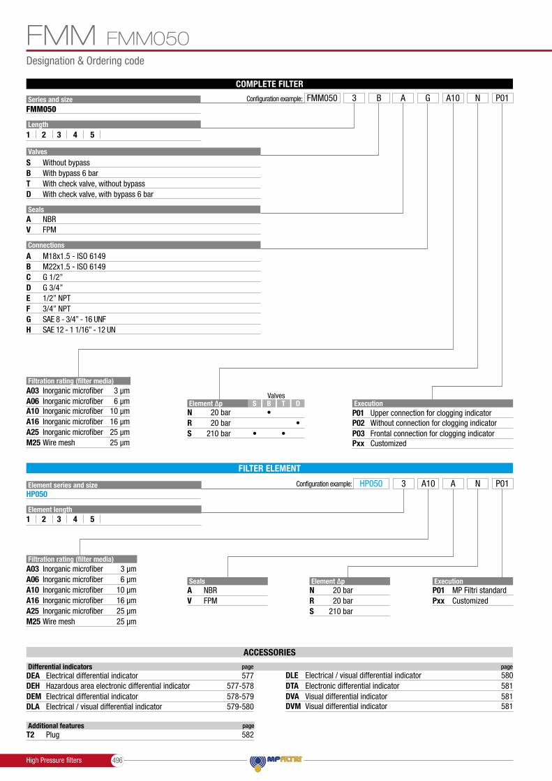
Designation & Ordering code
FMM
Element series and sizeHP050
Configuration example:
ExecutionP01Pxx
MP Filtri standardCustomized
HP050 A3 NA10 P01
Element ∆pNRS
20 bar20 bar
210 bar
Element length1 2 3 4 5
M25
A16A25
Wire mesh 25 µm
Inorganic microfiber 16 µmInorganic microfiber 25 µm
Filtration rating (filter media)A03
A10A06
Inorganic microfiber 3 µm
Inorganic microfiber 10 µmInorganic microfiber 6 µm Seals
AV
NBRFPM
FILTER ELEMENT
ValvesDTBS
•••
• Element ∆pNRS
20 bar20 bar
210 bar
ExecutionP01P02P03Pxx
Upper connection for clogging indicatorWithout connection for clogging indicatorFrontal connection for clogging indicatorCustomizedM25
A16A25
Wire mesh 25 µm
Inorganic microfiber 16 µmInorganic microfiber 25 µm
Filtration rating (filter media)A03
A10A06
Inorganic microfiber 3 µm
Inorganic microfiber 10 µmInorganic microfiber 6 µm
COMPLETE FILTER
Series and size Configuration example: FMM050 A3 NGB A10 P01FMM050
Valves
Length1 2 3 4
SealsAV
NBRFPM
Connections
5
A
DCB
F
H
E
G
M22x1.5 - ISO 6149G 1/2”G 3/4”
3/4” NPT
SAE 12 - 1 1/16” - 12 UNSAE 8 - 3/4” - 16 UNF
1/2” NPT
M18x1.5 - ISO 6149
SBT
Without bypassWith bypass 6 barWith check valve, without bypass
D With check valve, with bypass 6 bar
FMM050
ACCESSORIES
Additional features page
T2 Plug 582
Differential indicators page page
DEA DLEElectrical differential indicator 577 Electrical / visual differential indicator 580
DLADEM
Electrical / visual differential indicator 579-580Electrical differential indicator 578-579 DVA
DTA
DVMVisual differential indicator 581Electronic differential indicator
Visual differential indicator
581
581
DEH Hazardous area electronic differential indicator 577-578
High Pressure filters 496

HØ68
Dimensions
FMMFMM050
Filter length
H[mm]
12345
158195237285407
Connections R
A-B-C-DE-F-G-H
M103/8” UNC
FMM050
OUTIN
Execution P01 Execution P02 Execution P03
Connection for differential indicator
T2 plug Connection for differential indicator
T2 plug
Recommendedclearance spacefor maintenance
R - depth 12 mmNr. 3 holes
Drain plug only length 5
High Pressure filters497

Designation & Ordering code
FMM
Element series and sizeHP150
Configuration example:
ExecutionP01Pxx
MP Filtri standardCustomized
HP150 A2 NM25 P01
Element ∆pN 20 bar
Element length1 2 3
SealsAV
NBRFPM
FILTER ELEMENT
Element ∆pN 20 bar
ExecutionP01Pxx
MP Filtri standardCustomized
COMPLETE FILTER
Series and size Configuration example: FMM150 A2 ND 2B M25 P01FMM150
Valves
Length1 2 3
SealsAV
NBRFPM
Connections
Connection for differential indicator
C
1
F
H
E
3
G
D
2
G 1 1/4”
Upper connection
1” NPT
Frontal connection
SAE 16 - 1 5/16” - 12 UN1 1/4” NPT
SAE 20 - 1 5/8” - 12 UN
G 1”
Without connection
SB
Without bypassWith bypass 6 bar
FMM150
M25
A16A25
Wire mesh 25 µm
Inorganic microfiber 16 µmInorganic microfiber 25 µm
Filtration rating (filter media)A03
A10A06
Inorganic microfiber 3 µm
Inorganic microfiber 10 µmInorganic microfiber 6 µm
Filtration rating (filter media)A03
M25A10A06
A16A25
Inorganic microfiber
Wire mesh
3 µm
25 µmInorganic microfiber 10 µmInorganic microfiber 6 µm
Inorganic microfiber 16 µmInorganic microfiber 25 µm
ACCESSORIES
Additional features page
T2 Plug 582
Differential indicators page page
DEA DLEElectrical differential indicator 577 Electrical / visual differential indicator 580
DLADEM
Electrical / visual differential indicator 579-580Electrical differential indicator 578-579 DVA
DTA
DVMVisual differential indicator 581Electronic differential indicator
Visual differential indicator
581
581
DEH Hazardous area electronic differential indicator 577-578
High Pressure filters 498

Ø88
Dimensions
FMMFMM150
Filter length
H[mm]
123
230340415
Connections R
C-DE-F-G-H
M103/8” UNC
FMM150
OUTIN
Version 1 Version 2 Version 3
Connection for differential indicatorT2 plug not included
Connection for differential indicatorT2 plug not included
Recommendedclearance spacefor maintenance
R - depth 12 mmNr. 4 holes
High Pressure filters499

Order number for spare parts
3e
3d
3a
3b
3c
2
3f
4
3g
3e
3d
3a
3b
3c
2
3f
4
FMMFMM 050
FMM 150
Item:
Filter series
Seal Kit code numberFilterelement NBR FPM
Seeorder table
2Q.ty: 1 pc. Q.ty: 1 pc.Q.ty: 1 pc.
(3a ÷ 3g)3 4
Indicator connection plugNBR FPM
T2H T2V02050314 02050315FMM 050
Item:
Filter series
Seal Kit code numberFilterelement NBR FPM
Seeorder table
2Q.ty: 1 pc. Q.ty: 1 pc.Q.ty: 1 pc.
(3a ÷ 3f)3 4
Indicator connection plugNBR FPM
T2H T2V02050731 02050732FMM 150
SPARE PARTS
High Pressure fi lters 500

FMM
High Pressure filters501

High Pressure filters 502

HPB seriesMaximum working pressure up to 42 MPa (420 bar) - Flow rate up to 300 l/min
High Pressure fi lters
High Pressure fi lters503

HPB
Weights [kg] and volumes [dm3]
Weights [kg]
HPB 050HPB 150
Volumes [dm3]Length Length
0.300.45
0.80-
0.450.85
1.20-
0.601.10
1 42 53
1.102.90
2.40-
1.504.90
3.50-
1.906.30
1 42 53
GENERAL INFORMATION
- Housing: Phosphatized steelFilter housing materials
- Test pressure: 63 MPa (630 bar)- Burst pressure: 126 MPa (1260 bar)- Pulse pressure fatigue test: 1 000 000 cycles with pressure from 0 to 42 MPa (420 bar)
Pressure
- Microfi bre / Wire mesh fi lter elements - series N: 20 bar- Microfi bre / Wire mesh fi lter elements - series S: 210 bar- Fluid fl ow through the fi lter element from OUT to IN
∆p element type
- Standard NBR series A- Optional FPM series V
Seals
HPB fi lters are providedfor vertical mounting
Note
From -25 °C to +110 °CTemperature
High Pressure Bowl Kit
Maximum working pressure up to 42 MPa (420 bar)Flow rate up to 300 l/min
HPB is a range of high pressure bowl kits for protection of sensitive components in high pressure hydraulic systems in the mobile machines. They are directly integrated in the control blocks.
Available features:- Fine fi ltration rating, to get a good cleanliness level into the system - Low collapse fi lter element “N”, for use with blocks provided with bypass valve- High collapse fi lter element with external support “S”, for use with blocks not provided with the bypass valve
Description Technical data
Filter series
High Pressure fi lters 504

Style S
HPBGENERAL INFORMATION
Filter element design - N Series Filter element design - S Series
HPB 050
HPB 150
12345
123
LengthFilter series
Maximum flow rate for a complete pressure filter with a pressure drop ∆p = 1.5 bar.The reference fluid has a kinematic viscosity of 30 mm2/s (cSt) and a density of 0.86 kg/dm3.For different pressure drop or fluid viscosity we recommend to use our selection software available on www.mpfiltri.com.You can also calculate the right size using the formulas present on the FILTER SIZING paragraph at the beginning of the full catalogue or at the beginning of the filter family brochure.Please, contact our Sales Department for further additional information.
A03 A06 A10 A16 A25 M25 42 43 79 82 106 147 52 57 85 96 121 149 66 69 97 106 130 150 83 89 113 115 134 152 107 110 130 134 141 154
81 88 156 163 179 295 142 145 227 230 236 312 170 180 242 245 263 315
A03 A06 A10 A16 A25 29 39 57 59 74 45 49 76 88 114 58 61 89 99 125 74 80 106 108 129 93 95 111 121 139
FILTER ASSEMBLY SIZINGFlow rates [l/min]
Hydraulic symbols Filter series
••
HPB 050HPB 150
High Pressure filters505

Designation & Ordering code
HPB
Element series and sizeHP050
Configuration example: HP150 A3 NA10 P01
Element length1 2 3 4 5
FILTER ELEMENT
ExecutionP01Pxx
MP Filtri standardCustomized
ExecutionP01Pxx
MP Filtri standardCustomized
COMPLETE FILTER
Series and size NConfiguration example: HPB050 A103 A P01HPB050
Length1 2 3 4
Seals
Seals
A
A
V
V
NBR
NBR
FPM
FPM
5
HPB050
M25
A16A25
Wire mesh 25 µm
Inorganic microfiber 16 µmInorganic microfiber 25 µm
A03
A10A06
Inorganic microfiber 3 µm
Inorganic microfiber 10 µmInorganic microfiber 6 µm
Filtration rating (filter media)
M25
A16A25
Wire mesh 25 µm
Inorganic microfiber 16 µmInorganic microfiber 25 µm
A03
A10A06
Inorganic microfiber 3 µm
Inorganic microfiber 10 µmInorganic microfiber 6 µm
Filtration rating (filter media)
Element ∆pNS
20 bar210 bar
Element ∆pNS
20 bar210 bar
SealsAV
NBRFPM
High Pressure filters 506

32
22.5
20 18
2
8
Ø67
Ø62
Ø19
Ø23.7
Dimensions
HPB050
Filter length
H[mm]
12345
107144186234356
HPB050
O-Ring seal
Anti-extrusion ring
HPB
Drain plug only length 5 Recommended
clearance spacefor maintenance
H10
0
High Pressure filters507

Designation & Ordering code
Element series and sizeHP150
Configuration example: HP050 A3 NA10 P01
Element length1 2 3
FILTER ELEMENT
ExecutionP01Pxx
MP Filtri standardCustomized
ExecutionP01Pxx
MP Filtri standardCustomized
COMPLETE FILTER
Series and size NConfiguration example: HPB150 A103 A P01HPB150
Length1 2 3
Seals
Seals
A
A
V
V
NBR
NBR
FPM
FPM
M25
A16A25
Wire mesh 25 µm
Inorganic microfiber 16 µmInorganic microfiber 25 µm
A03
A10A06
Inorganic microfiber 3 µm
Inorganic microfiber 10 µmInorganic microfiber 6 µm
Filtration rating (filter media)
M25
A16A25
Wire mesh 25 µm
Inorganic microfiber 16 µmInorganic microfiber 25 µm
A03
A10A06
Inorganic microfiber 3 µm
Inorganic microfiber 10 µmInorganic microfiber 6 µm
Filtration rating (filter media)
Element ∆pN 20 bar
Element ∆pN 20 bar
SealsAV
NVRFPM
HPB HPB150
High Pressure filters 508

43
33.3
28.5
27 14
Ø86 M85x1.5
Ø80
Ø25
Ø31
1.5
Dimensions
HPB150
Filter length
H[mm]
123
161271346
HPB150 HPB
O-Ring seal
Anti-extrusion ring
Recommendedclearance spacefor maintenance
H12
5
High Pressure filters509

Order number for spare parts
HPBHPB 050
HPB 150
Item:
Filter series
Seal Kit code numberFilterelement NBR FPM
Seeorder table
2Q.ty: 1 pc.Q.ty: 1 pc.
(3a ÷ 3i)3
02050813 02050823HPB 050
Item:
Filter series
Seal Kit code numberFilterelement NBR FPM
Seeorder table
2Q.ty: 1 pc.Q.ty: 1 pc.
(3a ÷ 3c)3
02050816 02050826HPB 150
SPARE PARTS
3a
3b
3c
2
3a
3k
3b
3c
3i
2
High Pressure fi lters 510

HPB
High Pressure filters511

High Pressure fi lters 512

FHA 051 seriesMaximum working pressure up to 56 MPa (560 bar) - Flow rate up to 150 l/min
High Pressure fi lters
High Pressure fi lters513

GENERAL INFORMATIONFHA 051
- Opening pressure 600 kPa (6 bar) ±10%- Other opening pressures on request.
Bypass valve
- Micro� bre � lter elements - series N-R: 20 bar- Micro� bre � lter elements - series S: 210 bar- Wire mesh � lter elements - series N: 20 bar- Fluid � ow through the � lter element from OUT to IN
∆p element type
- Standard NBR series A- Optional FPM series V
Seals
FHA � lters are providedfor vertical mounting
Note
From -25 °C to +110 °CTemperature
In-line Inlet/OutletConnections
- Test pressure: 84 MPa (840 bar)- Burst pressure: 168 MPa (1680 bar)- Pulse pressure fatigue test: 1 00 000 cycles with pressure from 0 to 56 MPa (560 bar)
Pressure
- Head: Steel (chemical heat treatment)- Housing: Steel (chemical heat treatment)- Bypass valve: Steel
Filter housing materials
Weights [kg]
FHA 051
Volumes [dm3]Length Length
0.33 0.790.47 1.230.62
1 42 53
3.28 4.543.65 5.744.06
1 42 53
Weights [kg] and volumes [dm3]
Filter series
High Pressure � lters
In-lineMaximum working pressure up to 56 MPa (560 bar)Flow rate up to 150 l/min
FHA is a range of high pressure filter for protection of sensitive components in high pressure hydraulic systems in the mobile machines.They are directly connected to the lines of the system through the hydraulic � ttings.
Available features:- Female threaded connections up to 3/4”, for a maximum flow rate of 140 l/min- Fine � ltration rating, to get a good cleanliness level into the system- Bypass valve, to relieve excessive pressure drop across the � lter media- Check valve, to protect the system against reverse � ow- Reverse flow valve, to allow bidirectional flow through the filter housing. The back � ow is not � ltered- Low collapse filter element “N”, for use with filters provided with bypass valve- Low collapse � lter element with external support “R”, for � lter element protection against the back pressure caused by the check valve or the reverse � ow in � lters provided with the bypass valve- High collapse � lter element with external support “S”, for � lter element protection against the back pressure caused by the check valve or the reverse � ow in � lters not provided with the bypass valve- Visual, electrical and electronic differential clogging indicators
Common applications:Delivery lines, in any heavy duty industrial equipment or mobile machines
Description Technical data
High Pressure � lters 514

GENERAL INFORMATION FHA 051
The curves are plotted using mineral oil with density of 0.86 kg/dm3 in compliance with ISO 3968. ∆p varies proportionally with density.
Filter housings ∆p pressure drop
Bypass valve pressure drop
FHA 051 FHA 051
1.50
1.00
0.50
0.000 30 60 90 120 150
3/4”
1/2”
FHA 051Maximum pressure
560 barFlow rate to 140 l/min
FHA 051
4.50
3.00
1.50
0.000 20 40 60 80 100
1
FHA - Pressure drop in Reverse flow valves
1 - Reverse flow2 - In filter direction
Valves (for FHA)
Bypass valve pressure drop
15
10
5
00 30 60 90 120 150
2
Pressure drop in reverse flow valves
1 - Reverse flow2 - In filter direction
Pressure drop
Flow rate l/min Flow rate l/min
Flow rate l/min
∆p b
ar
∆p b
ar
∆p b
ar
FHA 051Style S Style B Style V Style ZStyle T Style D Filter series
••••••
OUT
D.I.
IN
OUT
D.I.
IN
OUT
D.I.
IN
OUT
D.I.
IN
OUT
D.I.
IN
OUT
D.I.
IN
Hydraulic symbols
12345
FHA 051
Filter element design - N Series Filter element design - R Series Filter element design - S SeriesLengthFilter series
Maximum flow rate for a complete pressure filter with a pressure drop ∆p = 1.5 bar.The reference fluid has a kinematic viscosity of 30 mm2/s (cSt) and a density of 0.86 kg/dm3.For different pressure drop or fluid viscosity we recommend to use our selection software available on www.mpfiltri.com.You can also calculate the right size using the formulas present on the FILTER SIZING paragraph at the beginning of the full catalogue or at the beginning of the filter family brochure.Please, contact our Sales Department for further additional information.
42 41 82 85 110 156 53 58 87 100 127 158 68 71 101 111 137 160 86 92 118 121 142 162 112 115 137 142 150 165
42 41 82 85 110 53 58 87 100 127 68 71 101 111 137 86 92 118 121 142 112 115 137 142 150
30 40 58 60 76 45 50 78 91 120 59 62 92 103 131 77 83 110 113 137 96 99 116 128 147
A03 A06 A10 A16 A25 M25 A03 A06 A10 A16 A25 A03 A06 A10 A16 A25
FILTER ASSEMBLY SIZINGFlow rates [l/min]
High Pressure filters515

Designation & Ordering code
Element series and sizeHP050
Configuration example:
ExecutionP01Pxx
MP Filtri standardCustomized
HP050 A3 NA10 P01
Element ∆pNRS
20 bar20 bar
210 bar
Element length1 2 3 4 5
M25
A16A25
Wire mesh 25 µm
Inorganic microfiber 16 µmInorganic microfiber 25 µm
Filtration rating (filter media)A03
A10A06
Inorganic microfiber 3 µm
Inorganic microfiber 10 µmInorganic microfiber 6 µm Seals
AV
NBRFPM
FILTER ELEMENT
ValvesD ZT VBS
• ••• •
• Element ∆pNRS
20 bar20 bar
210 bar
ExecutionP01P02P03Pxx
Upper connection for clogging indicatorWithout connection for clogging indicatorFrontal connection for clogging indicatorCustomizedM25
A16A25
Wire mesh 25 µm
Inorganic microfiber 16 µmInorganic microfiber 25 µm
Filtration rating (filter media)A03
A10A06
Inorganic microfiber 3 µm
Inorganic microfiber 10 µmInorganic microfiber 6 µm
COMPLETE FILTER
Series and size Configuration example: FHA051 A3 NGB A10 P01FHA051
Valves
Length1 2 3 4
SealsAV
NBRFPM
Connections
5
A
DCB F
H
E
GM22x1.5 - ISO 6149G 1/2”G 3/4”
3/4” NPT
SAE 12 - 1 1/16” - 12 UNSAE 8 - 3/4” - 16 UNF
1/2” NPTM18x1.5 - ISO 6149
SBT
Without bypassWith bypass 6 barWith check valve, without bypass
DVZ
With check valve, with bypass 6 barWith reverse flow, without bypassWith reverse flow, with bypass 6 bar
FHA 051
ACCESSORIES
Additional features page
T2 Plug 582
Differential indicators page page
DEA DLEElectrical differential indicator 577 Electrical / visual differential indicator 580
DLADEM
Electrical / visual differential indicator 579-580Electrical differential indicator 578-579 DVA
DTA
DVMVisual differential indicator 581Electronic differential indicator
Visual differential indicator
581
581
DEH Hazardous area electronic differential indicator 577-578
High Pressure filters 516

Dimensions
H
Ø68
FHA051
Filter length
H[mm]
12345
158195237285407
Connections R
A-B-C-DE-F-G-H
M103/8” UNC
OUTIN
Execution P01
Execution P01
Execution P02
Valves S - B - T - D
Valves V - Z
Execution P02
Execution P03
Execution P03
Connection for differential indicator
T2 plug
Connection for differential indicator
T2 plug
Connection for differential indicator
T2 plug
Connection for differential indicator
T2 plug
Recommendedclearance spacefor maintenance
R - depth 12 mmNr. 3 holes
Drain plug only length 5
FHA 051
High Pressure filters517
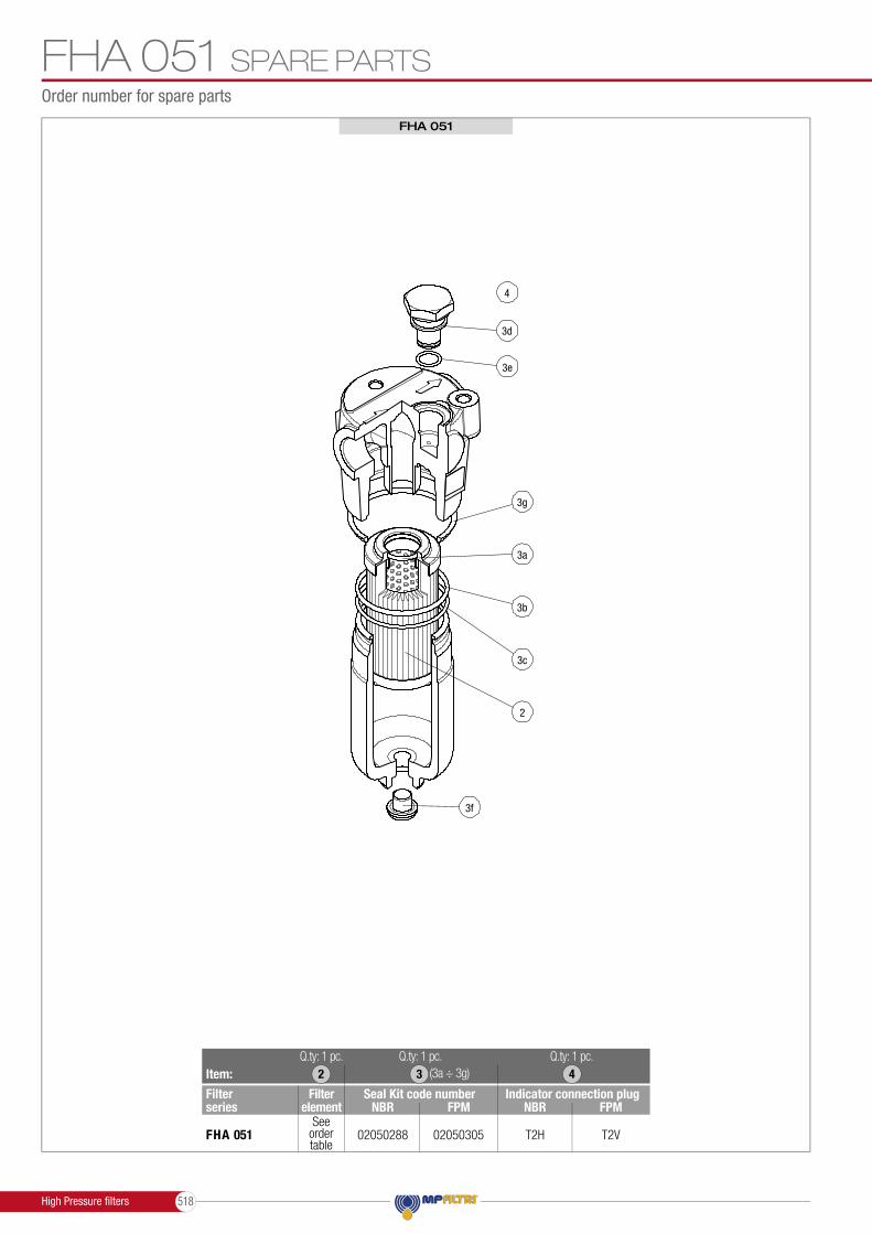
Order number for spare parts
3e
3d
3a
3b
3c
2
3f
4
3g
SPARE PARTS
FHA 051
Item:
Filter series
Seal Kit code numberFilterelement NBR FPM
Seeorder table
2Q.ty: 1 pc. Q.ty: 1 pc.Q.ty: 1 pc.
(3a ÷ 3g)3 4
Indicator connection plugNBR FPM
T2H T2V02050288 02050305FHA 051
FHA 051
High Pressure fi lters 518

FHA 051
High Pressure filters519

High Pressure fi lters 520

FHM seriesMaximum working pressure up to 32 MPa (320 bar) - Flow rate up to 400 l/min
High Pressure fi lters
High Pressure fi lters521

GENERAL INFORMATIONFHM
Weights [kg] and volumes [dm3]
2.17 - - - - - 4.74 5.95 - - - 4.74 5.95 - - 5.31 5.68 6.09 6.56 7.74 5.47 5.83 7.04 - - 8.78 10.38 11.43 - - 19.80 21.93 24.22 26.70 - 35.00 39.17 42.69 54.70 60.50
1 2 3 4 5 0.12 - - - - - 0.30 0.50 - - - 0.30 0.50 - - 0.29 0.38 0.48 0.60 0.89 0.27 0.34 0.56 - - 0.49 0.82 1.03 - - 1.04 1.76 2.53 3.36 - 1.63 2.35 2.96 5.11 6.44
1 2 3 4 5Length LengthWeights [kg]
FHM 006FHM 007FHM 010FHM 050FHM 065FHM 135FHM 320FHM 500
Volumes [dm3] Filter series
High Pressure fi lters
ManifoldMaximum working pressure up to 32 MPa (320 bar)Flow rate up to 400 l/min
FHM is a range of high pressure fi lter for protection of sensitive components in high pressure hydraulic systems in the mobile machines.They are directly connected to the top of the manifold, through the proper fl anged interface.
Available features:Available features:- Manifold connections up to Ø30 mm, for a maximum fl ow rate of 450 l/min- ISO 4401 CETOP 3 and CETOP 5 interface, for direct mounting on the CETOP valves- Fine fi ltration rating, to get a good cleanliness level into the system- Bypass valve, to relieve excessive pressure drop across the fi lter media- Check valve, to protect the system against reverse fl ow- Low collapse fi lter element “N”, for use with fi lters provided with bypass valve- High collapse filter element “H”, for use with filters not provided with bypass valve- High collapse fi lter element with external support “S”, for fi lter element protection against the back pressure caused by the check valve in fi lters not provided with the bypass valve- Visual, electrical and electronic differential clogging indicators
Common applications:Delivery lines, in any high pressure industrial equipment
- Head Phosphatized cast iron: FHM 006-007-010 Phosphatized steel: FHM 050-065-135-320-500
- Housing: Phosphatized steel
- Bypass valve: Steel
- Check valve: Steel
Filter housing materials
- Test pressure: 48 MPa (480 bar)- Burst pressure: 96 MPa (960 bar)- Pulse pressure fatigue test: 1 000 000 cycles with pressure from 0 to 32 MPa (320 bar)
Pressure
From -25 °C to +110 °CTemperature
- Opening pressure 600 kPa (6 bar) ±10%- Other opening pressures on request.
Bypass valve
- Microfi bre fi lter elements - series N: 20 bar (not available for FHM 006, FHM 007 and FHM 010)- Microfi bre fi lter elements - series H: 210 bar (not available for FHM 050 and FHM 500)- Microfi bre fi lter elements - series S: 210 bar (only for FHM 050 and FHM 500)- Wire mesh fi lter elements - series N: 20 bar (not available for FHM 006)- Wire mesh fi lter elements - series H: 210 bar (not available for FHM 050 and FHM 500)- Fluid fl ow through the fi lter element from OUT to IN
∆p element type
- Standard NBR series A- Optional FPM series V
Seals
FHM fi lters are provided for vertical mounting
Note
Manifold mountingConnections
Description Technical data
High Pressure fi lters 522

GENERAL INFORMATION FHMFILTER ASSEMBLY SIZING
Flow rates [l/min]
Hydraulic symbols
123
1234
FHM 320
FHM 135
Maximum flow rate for a complete pressure filter with a pressure drop ∆p = 1.5 bar.The reference fluid has a kinematic viscosity of 30 mm2/s (cSt) and a density of 0.86 kg/dm3.For different pressure drop or fluid viscosity we recommend to use our selection software available on www.mpfiltri.com.You can also calculate the right size using the formulas present on the FILTER SIZING paragraph at the beginning of the full catalogue or at the beginning of the filter family brochure.Please, contact our Sales Department for further additional information.
Filter element design - H Series
1LengthFilter series
FHM 006
23
FHM 007
23
FHM 010
A03 A06 A10 A16 A25 M25 9 10 13 14 15 16
13 13 15 16 16 16 15 15 16 16 17 17
23 25 32 34 37 38 31 33 37 38 39 40
Filter element design - N Series
Filter element design - N Series
Filter element design - S Series
Filter element design - S Series
12345
12345
Length
Length
Filter series
Filter series
FHM 050
FHM 500
A03 A06 A10 A16 A25 M25
A03 A06 A10 A16 A25 M25
38 37 65 67 81 101 46 50 69 75 89 102 57 59 76 81 93 103 68 71 84 86 95 103 82 83 93 95 98 105
211 232 281 289 309 394 242 262 303 308 330 397 284 294 336 338 357 399 302 325 346 350 361 401 325 334 356 361 373 401
A03 A06 A10 A16 A25
A03 A06 A10 A16 A25
28 36 50 52 62 41 44 63 71 85 51 53 71 77 90 62 66 81 82 93 73 75 83 89 97
126 135 208 210 261 187 206 258 266 285 226 230 285 290 315 251 273 314 315 341 296 301 335 338 360
Filter element design - N Series Filter element design - H Series
123
LengthFilter series
FHM 065
A03 A06 A10 A16 A25 M25 23 30 48 53 71 102 30 45 59 64 81 103 52 60 78 82 92 105
61 65 99 104 131 149 91 96 118 119 155 167 118 119 144 146 156 168
112 121 187 217 252 312 200 214 281 293 320 328 245 267 312 320 325 333 267 281 315 325 336 341
A03 A06 A10 A16 A25 22 23 43 50 67 30 34 56 62 76 51 58 77 81 91
46 51 83 86 122 79 92 109 111 134 103 112 130 137 146
97 102 156 162 228 161 181 237 241 282 207 233 275 280 306 232 247 279 283 309
Filter series Stile SFHM 006FHM 007FHM 010FHM 050FHM 065FHM 135FHM 320FHM 500
• • • •
•
• • • •
••
• • • •
• • • •• • • •
Stile S Stile S Stile B Stile T Stile D
OUT
D.I.
IN
D.I.
A P T B
OUT
D.I.
IN
OUT
D.I.
IN
OUT
D.I.
IN
D.I.
AT P T B
High Pressure filters523

GENERAL INFORMATIONFHMPressure drop
The curves are plotted using mineral oil with density of 0.86 kg/dm3 in compliance with ISO 3968. ∆p varies proportionally with density.
Bypass valve pressure drop
Filter housings ∆p pressure drop
4.50
3.00
1.50
0.000 12 24 36 48 60
4.50
3.00
1.50
0.000 6 12 18 24 30
FHM 006 - 007
1.50
1.00
0.50
0.000 20 40 60 80 100
FHM 010
FHM 050 - 065
Valves
Bypass valve pressure drop
15
10
5
00 18 36 54 72 90
15
10
5
00 12 24 36 48 60
FHM 050 - 065
FHM 135
15
10
5
00 18 36 54 72 90
FHM 320
1.50
1.00
0.50
0.000 30 60 90 120 150
FHM 1351.50
1.00
0.50
0.000 70 140 210 280 350
FHM 320
1.50
1.00
0.50
0.000 90 180 270 360 450
FHM 500
4.50
3.00
1.50
0.000 12 24 36 48 60
4.50
3.00
1.50
0.000 6 12 18 24 30
FHM 006 - 007
1.50
1.00
0.50
0.000 20 40 60 80 100
FHM 010
FHM 050 - 065
Valves
Bypass valve pressure drop
15
10
5
00 18 36 54 72 90
15
10
5
00 12 24 36 48 60
FHM 050 - 065
FHM 135
15
10
5
00 18 36 54 72 90
FHM 320
1.50
1.00
0.50
0.000 30 60 90 120 150
FHM 1351.50
1.00
0.50
0.000 70 140 210 280 350
FHM 320
1.50
1.00
0.50
0.000 90 180 270 360 450
FHM 500
Flow rate l/min Flow rate l/min
Flow rate l/min Flow rate l/min
Flow rate l/min
Flow rate l/min
Flow rate l/min
Flow rate l/min
Flow rate l/min
∆p b
ar
∆p b
ar
∆p b
ar
∆p b
ar
∆p b
ar∆p
bar
∆p b
ar∆p
bar
∆p b
ar
Check Valve
Check ValveCheck Valve
High Pressure filters 524

FHM
High Pressure filters525

Designation & Ordering code
COMPLETE FILTER
Series and size Configuration example: FHM010 V2 HG1S A03 P01
S Without bypass Valves
FHM006 - FHM007 - FHM010FHM
ExecutionP01Pxx
MP Filtri standardCustomized
M25
A16A25
Wire mesh 25 µm
Inorganic microfiber 16 µmInorganic microfiber 25 µm
Filtration rating (filter media)A03
A10A06
Inorganic microfiber 3 µm
Inorganic microfiber 10 µmInorganic microfiber 6 µm
SealsAV
NBRFPM
ConnectionsG1G2
Manifold side “A”Manifold side “B”
FILTER ELEMENT
Element series and size Configuration example:
ExecutionP01Pxx
MP Filtri standardCustomized
HP065 A2 HA03 P01
Element ∆p
Element ∆p
H
H
210 bar
210 bar
Filtration rating (filter media)A03
M25A10A06
A16A25
Inorganic microfiber
Wire mesh
3 µm
25 µmInorganic microfiber 10 µmInorganic microfiber 6 µm
Inorganic microfiber 16 µmInorganic microfiber 25 µm
HP011HP065
Element length23
FHM010
FHM010
FHM007
FHM007
FHM006
FHM006
•••
•
•
•
•
•
FHM006 FHM007 FHM010
Length123
FHM010FHM007FHM006•
••••
SealsAV
NBRFPM
ACCESSORIES
Additional features page
T2 Plug 582
Differential indicators page page
DEA DLEElectrical differential indicator 577 Electrical / visual differential indicator 580
DLADEM
Electrical / visual differential indicator 579-580Electrical differential indicator 578-579 DVA
DTA
DVMVisual differential indicator 581Electronic differential indicator
Visual differential indicator
581
581
DEH Hazardous area electronic differential indicator 577-578
High Pressure filters 526

Dimensions
FHM006 - FHM007 - FHM010 FHMFHM006
FHM006
Ø46
Ø46
Connection G1
Connection G2
OUT
OUT
IN
IN
Connection for differential indicatorT2 plug not included
Connection for differential indicatorT2 plug not included
Nr. 4 holes
Nr. 4 holes
Mounting surface
Mounting surface
High Pressure filters527

Ø68
Ø68
Dimensions
FHM006 - FHM007 - FHM010FHMFHM007
FHM007
Connection G1
Connection G2
Filter length
H[mm]
23
265366
Filter length
H[mm]
23
265366
OUT
OUT
IN
IN
Connection for differential indicatorT2 plug not included
Connection for differential indicatorT2 plug not included
Nr. 4 holes
Nr. 4 holes
Mounting surface
Mounting surface
Recommended clearance space for maintenance
Recommended clearance space for maintenance
High Pressure filters 528

Ø68
Ø68
Dimensions
FHM006 - FHM007 - FHM010 FHMFHM010
FHM010
Connection G1
Connection G2
Filter length
H[mm]
23
280381
Filter length
H[mm]
23
280381
OUT
OUT
IN
IN
Connection for differential indicatorT2 plug not included
Connection for differential indicatorT2 plug not included
Nr. 4 holes
Nr. 4 holes
Mounting surface
Mounting surface
Recommended clearance space for maintenance
Recommended clearance space for maintenance
High Pressure filters529

Designation & Ordering code
COMPLETE FILTER
Series and size Configuration example: FHM135 A3 HF1S A10 P01
Valves
FHM050 - FHM065 - FHM135FHM
ExecutionP01Pxx
MP Filtri standardCustomized
M25
A16A25
Wire mesh 25 µm
Inorganic microfiber 16 µmInorganic microfiber 25 µm
Filtration rating (filter media)A03
A10A06
Inorganic microfiber 3 µm
Inorganic microfiber 10 µmInorganic microfiber 6 µm
SealsAV
NBRFPM
ConnectionsF1 Manifold
FILTER ELEMENT
Element series and size Configuration example:
ExecutionP01Pxx
MP Filtri standardCustomized
HP135 A3 HA10 P01
Element ∆pNHS
20 bar210 bar210 bar
Filtration rating (filter media)A03
M25A10A06
A16A25
Inorganic microfiber
Wire mesh
3 µm
25 µmInorganic microfiber 10 µmInorganic microfiber 6 µm
Inorganic microfiber 16 µmInorganic microfiber 25 µm
FHM050 FHM065 FHM135
Length12
43
5
FHM135FHM065FHM050•• •
•••
••••
•
SealsAV
NBRFPM
HP050 HP065 HP135
Element length12345
HP135HP065HP050•••••••••
••
SBT
Without bypassWith bypass 6 barWith check valve, without bypass
D With check valve, with bypass 6 bar
Valves:B DS
FHM050
HP050 HP065 HP135
T B DSFHM065-135
T• •• •
• ••
• • •• •
•
•
Element ∆pNHS
20 bar210 bar210 bar
ACCESSORIES
Additional features page
T2 Plug 582
Differential indicators page page
DEA DLEElectrical differential indicator 577 Electrical / visual differential indicator 580
DLADEM
Electrical / visual differential indicator 579-580Electrical differential indicator 578-579 DVA
DTA
DVMVisual differential indicator 581Electronic differential indicator
Visual differential indicator
581
581
DEH Hazardous area electronic differential indicator 577-578
High Pressure filters 530

Dimensions
FHM050 - FHM065 - FHM135 FHMFHM050 FHM065
Filter length
Filter length
H[mm]
H[mm]
12345
123
154191233281403
162193295
Ø68
OUTIN
Connection for differential indicatorT2 plug not included
Recommended clearance space for maintenance
Nr. 4 holes
High Pressure filters531

Dimensions
FHM050 - FHM065 - FHM135FHMFHM135
Filter length
H[mm]
123
202315390
Ø77
OUTIN
Connection for differential indicatorT2 plug not included
Recommended clearance space for maintenance
depth 13 mmNr. 4 holes
Nr. 4 holes
High Pressure filters 532

FHM
High Pressure filters533

Designation & Ordering code
FHM320 - FHM500FHM
COMPLETE FILTER
Series and size Configuration example: FHM320 A4 NF1D A06 P01
Valves
M25
A16A25
Wire mesh 25 µm
Inorganic microfiber 16 µmInorganic microfiber 25 µm
Filtration rating (filter media)A03
A10A06
Inorganic microfiber 3 µm
Inorganic microfiber 10 µmInorganic microfiber 6 µm
SealsAV
NBRFPM
ConnectionsF1 Manifold
FILTER ELEMENT
Element series and size Configuration example:
ExecutionP01Pxx
MP Filtri standardCustomized
HP320 A4 NA06 P01
Filtration rating (filter media)A03
M25A10A06
A16A25
Inorganic microfiber
Wire mesh
3 µm
25 µmInorganic microfiber 10 µmInorganic microfiber 6 µm
Inorganic microfiber 16 µmInorganic microfiber 25 µm
FHM320 FHM500
Length12
43
5
FHM500FHM320
•
•
•••
•
•
••
SealsAV
NBRFPM
HP320 HP500
Element length12345
HP500HP320•••
•
••
•
••
SBT
Without bypassWith bypass 6 barWith check valve, without bypass
D With check valve, with bypass 6 bar
ExecutionP01P02Pxx
MP Filtri standardMaintenance from the bottom of the housingCustomized
4 5321• ••••• •
Filter lengthValves:B DS
FHM320T B DS
FHM500T
• •• •
• •• •
Element ∆pNHS
20 bar210 bar210 bar
Element ∆pNHS
20 bar210 bar210 bar
HP320 HP500• •
••
ACCESSORIES
Additional features page
T2 Plug 582
Differential indicators page page
DEA DLEElectrical differential indicator 577 Electrical / visual differential indicator 580
DLADEM
Electrical / visual differential indicator 579-580Electrical differential indicator 578-579 DVA
DTA
DVMVisual differential indicator 581Electronic differential indicator
Visual differential indicator
581
581
DEH Hazardous area electronic differential indicator 577-578
High Pressure filters 534

Ø101
Dimensions
FHM320 - FHM500 FHMFHM320
Length 1 - 2 - 3 Length 4
Filter length
H[mm]
H2 [mm]Execution
P01 P021234
293416548702
150150150150
---
550
OUT IN
Recommended clearance space for maintenance
Recommended clearance space for maintenance
Nr. 6 holes
Connection for differential indicatorT2 plug not included
Connection for differential indicator
T2 plug
Drainplug
High Pressure filters535

Ø133
Dimensions
FHM320 - FHM500FHMFHM500
Length 1 - 2 - 3 Length 4 - 5
Filter length
H[mm]
H2 [mm]Execution
P01 P0212345
355445521679845
150150150150150
---
480650
OUT IN
Recommended clearance space for maintenance
Recommended clearance space for maintenance
Nr. 6 holes
Connection for differential indicatorT2 plug not included
Connection for differential indicator
T2 plugDrainplug
High Pressure filters 536

FHMOrder number for spare parts
SPARE PARTS
3e
3d
3a
3b
3c
2
3f
4
3n
3e
3b
3a
3b
3c
2
3h 3m
5
3g
3f
4
3d
3c
3h 3m
6
Item:
Filter series
Seal Kit code numberFilterelement NBR FPM
Seeorder table
2Q.ty: 1 pc. Q.ty: 1 pc.Q.ty: 1 pc.
(3a ÷ 3f)3 4
Indicator connection plugNBR FPM
T2H T2V02050324 02050325FHM 0060205060002050320
0205060102050321
FHM 007FHM 010
Item:
Filter series
Seal Kit code numberFilterelement NBR FPM
Seeorder table
2Q.ty: 1 pc. Q.ty: 1 pc. Q.ty: 1 pc. Q.ty: 1 pc.Q.ty: 1 pc.
(3a ÷ 3m)3 4 5 6
Indicator connection plug Bypass assembly Non-bypass assemblyNBR NBR NBRFPM FPM FPM
T2H T2V
02050410 02001400 0200140202050411 02001401 02001403FHM 05002050268
02050275
02001400
02001408
02001402
0200141002050271
02050332
02001404
02001408
02001406
02001410
02050279
02050286
02001401
02001409
02001403
0200141102050282
02050333
02001405
02001409
02001407
02001411
FHM 065
FHM 320FHM 135
FHM 500
FHM 006 - 007 - 010
FHM 050 - 065 - 135 - 320 - 500
High Pressure fi lters537

High Pressure filters 538

FHB seriesMaximum working pressure up to 32 MPa (320 bar) - Flow rate up to 485 l/min
High Pressure fi lters
High Pressure fi lters539

GENERAL INFORMATIONFHB
- Head: Phosphatized cast iron- Housing: Phosphatized steel- Bypass valve: Steel- Check valve: Steel
Filter housing materials
- Working pressure: 32 MPa (320 bar)- Test pressure: 48 MPa (480 bar)- Burst pressure: 96 MPa (960 bar)- Pulse pressure fatigue test: 1 000 000 cycles with pressure from 0 to 32 MPa (320 bar)
Pressure
From -25 °C to +110 °CTemperature
- Opening pressure 600 kPa (6 bar) ±10%- Other opening pressures on request.
Bypass valve
- Microfi bre fi lter elements - series N: 20 bar- Microfi bre fi lter elements - series H: 210 bar (not available for FHB050)- Microfi bre fi lter elements - series S: 210 bar (only for FHB050)- Wire mesh fi lter elements - series N: 20 bar- Fluid fl ow through the fi lter element from OUT to IN
∆p element type
- Standard NBR series A- Optional FPM series V
Seals
FHB fi lters are provided for vertical mounting
Note
Manifold mountingConnections
Weights [kg] and volumes [dm3]Weights [kg]
FHB 050FHB 065FHB 135FHB 320
Volumes [dm3]Length Length
0.210.200.400.91
0.52--
3.59
0.300.270.731.63
0.81---
0.400.490.942.40
1 42 532.613.336.61
12.95
3.86--
26.77
2.983.698.21
15.08
5.04---
3.394.909.21
17.37
1 42 53 Filter series
High Pressure fi lters
ManifoldMaximum working pressure up to 32 MPa (320 bar)Flow rate up to 485 l/min
FHB is a range of high pressure filter for protection of sensitive components in high pressure hydraulic systems in the mobile machines.They are directly connected to the side of the manifold, through the proper fl anged interface.
Available features:- Manifold connections up to Ø30 mm, for a maximum fl ow rate of 485 l/min- Fine fi ltration rating, to get a good cleanliness level into the system- Bypass valve, to relieve excessive pressure drop across the fi lter media- Check valve, to protect the system against reverse fl ow- Low collapse filter element “N”, for use with filters provided with bypass valve- High collapse fi lter element “H”, for use with fi lters not provided with bypass valve- High collapse fi lter element with external support “S”, for fi lter element protection against the back pressure caused by the check valve in fi lters not provided with the bypass valve- Visual, electrical and electronic differential clogging indicators
Common applications:Delivery lines, in any high pressure industrial equipment or mobile machines
Description Technical data
High Pressure fi lters 540

GENERAL INFORMATION FHBFILTER ASSEMBLY SIZING
Flow rates [l/min]
Hydraulic symbols Filter seriesFHB 050FHB 065FHB 135FHB 320
Style S Style B Style T Style D
OUT
D.I.
IN
OUT
D.I.
IN
OUT
D.I.
IN
OUT
D.I.
IN
•••
•••
•••
•
••
12345
123
FHB 050
FHB 065
1234
FHB 320
123
FHB 135
Length
Length
Filter series
Filter series
Maximum flow rate for a complete pressure filter with a pressure drop ∆p = 1.5 bar.The reference fluid has a kinematic viscosity of 30 mm2/s (cSt) and a density of 0.86 kg/dm3.For different pressure drop or fluid viscosity we recommend to use our selection software available on www.mpfiltri.com.You can also calculate the right size using the formulas present on the FILTER SIZING paragraph at the beginning of the full catalogue or at the beginning of the filter family brochure.Please, contact our Sales Department for further additional information.
Filter element design - N Series
Filter element design - N Series
Filter element design - S Series
Filter element design - H Series
A03 A06 A10 A16 A25
A03 A06 A10 A16 A25
30 40 58 60 74 46 50 76 86 108 59 62 87 95 115 74 80 101 103 119 90 92 105 113 126
23 25 49 58 81 33 38 66 75 94 60 68 95 102 116
49 55 97 100 160 90 110 137 140 182 126 142 175 187 207
110 117 192 201 304 200 230 319 325 392 269 312 381 389 432 311 334 388 394 437
A03 A06 A10 A16 A25 M25
A03 A06 A10 A16 A25 M25
43 42 79 81 101 131 53 58 84 93 112 132 67 70 94 101 119 133 82 87 106 108 122 134 102 104 119 122 127 136
25 33 55 62 87 133 33 51 70 76 101 134 60 71 97 103 118 138
67 72 120 129 177 212 109 116 152 154 224 250 153 155 201 205 226 253
130 143 238 286 343 442 259 281 391 409 454 468 332 368 441 455 463 476 368 390 446 462 481 488
High Pressure filters541

GENERAL INFORMATIONFHBPressure drop
The curves are plotted using mineral oil with density of 0.86 kg/dm3 in compliance with ISO 3968. ∆p varies proportionally with density.
Filter housings ∆p pressure drop
Bypass valve pressure drop
0.90
0.60
0.30
0.000 40 80 120 160 200
0.90
0.60
0.30
0.000 20 40 60 80 100
FHB 050 - 065
0.90
0.60
0.30
0.000 75 150 225 300 375
FHB 135
FHB 320
266
15
10
5
00 18 36 54 72 90
15
10
5
00 12 24 36 48 60
FHB 050 - 065
FHB 135
15
10
5
00 50 100 150 200 250
FHB 320
Valves
Bypass valve pressure drop0.90
0.60
0.30
0.000 40 80 120 160 200
0.90
0.60
0.30
0.000 20 40 60 80 100
FHB 050 - 065
0.90
0.60
0.30
0.000 75 150 225 300 375
FHB 135
FHB 320
266
15
10
5
00 18 36 54 72 90
15
10
5
00 12 24 36 48 60
FHB 050 - 065
FHB 135
15
10
5
00 50 100 150 200 250
FHB 320
Valves
Bypass valve pressure drop
0.90
0.60
0.30
0.000 40 80 120 160 200
0.90
0.60
0.30
0.000 20 40 60 80 100
FHB 050 - 065
0.90
0.60
0.30
0.000 75 150 225 300 375
FHB 135
FHB 320
266
15
10
5
00 18 36 54 72 90
15
10
5
00 12 24 36 48 60
FHB 050 - 065
FHB 135
15
10
5
00 50 100 150 200 250
FHB 320
Valves
Bypass valve pressure drop
0.90
0.60
0.30
0.000 40 80 120 160 200
0.90
0.60
0.30
0.000 20 40 60 80 100
FHB 050 - 065
0.90
0.60
0.30
0.000 75 150 225 300 375
FHB 135
FHB 320
266
15
10
5
00 18 36 54 72 90
15
10
5
00 12 24 36 48 60
FHB 050 - 065
FHB 135
15
10
5
00 50 100 150 200 250
FHB 320
Valves
Bypass valve pressure drop
0.90
0.60
0.30
0.000 40 80 120 160 200
0.90
0.60
0.30
0.000 20 40 60 80 100
FHB 050 - 065
0.90
0.60
0.30
0.000 75 150 225 300 375
FHB 135
FHB 320
266
15
10
5
00 18 36 54 72 90
15
10
5
00 12 24 36 48 60
FHB 050 - 065
FHB 135
15
10
5
00 50 100 150 200 250
FHB 320
Valves
Bypass valve pressure drop
0.90
0.60
0.30
0.000 40 80 120 160 200
0.90
0.60
0.30
0.000 20 40 60 80 100
FHB 050 - 065
0.90
0.60
0.30
0.000 75 150 225 300 375
FHB 135
FHB 320
266
15
10
5
00 18 36 54 72 90
15
10
5
00 12 24 36 48 60
FHB 050 - 065
FHB 135
15
10
5
00 50 100 150 200 250
FHB 320
Valves
Bypass valve pressure drop
Flow rate l/min
Flow rate l/min
Flow rate l/min
Flow rate l/min
Flow rate l/min
Flow rate l/min
∆p b
ar
∆p b
ar
∆p b
ar
∆p b
ar∆p
bar
∆p b
ar
Check ValveCheck Valve
Check Valve
High Pressure filters 542

FHB
High Pressure filters543

Designation & Ordering code
COMPLETE FILTER
FHB FHB050
ValvesDTBS•
•••
Element ∆pNS
20 bar210 bar
Series and size Configuration example: FHB050 A2 SF1T A06 P01FHB050
Valves
Length1 2 3 4
SealsAV
NBRFPM
Connections
5
F1 Manifold
SBT
Without bypassWith bypass 6 barWith check valve, without bypass
D With check valve, with bypass 6 bar
ExecutionP01Pxx
MP Filtri standardCustomized
Element series and sizeHP050
Configuration example:
ExecutionP01Pxx
MP Filtri standardCustomized
HP050 A2 SA06 P01
Element ∆pNS
20 bar210 bar
Element length1 2 3 4 5
SealsAV
NBRFPM
FILTER ELEMENT
Filtration rating (filter media)A03
M25A10A06
A16A25
Inorganic microfiber
Wire mesh
3 µm
25 µmInorganic microfiber 10 µmInorganic microfiber 6 µm
Inorganic microfiber 16 µmInorganic microfiber 25 µm
M25
A16A25
Wire mesh 25 µm
Inorganic microfiber 16 µmInorganic microfiber 25 µm
Filtration rating (filter media)A03
A10A06
Inorganic microfiber 3 µm
Inorganic microfiber 10 µmInorganic microfiber 6 µm
ACCESSORIES
Additional features page
T2 Plug 582
Differential indicators page page
DEA DLEElectrical differential indicator 577 Electrical / visual differential indicator 580
DLADEM
Electrical / visual differential indicator 579-580Electrical differential indicator 578-579 DVA
DTA
DVMVisual differential indicator 581Electronic differential indicator
Visual differential indicator
581
581
DEH Hazardous area electronic differential indicator 577-578
High Pressure filters 544

Dimensions
FHBFHB050
FHB050
Filter length
H[mm]
12345
185222264312434
Ø68
OUT
IN
Recommended clearance space for maintenance
Drain plugonly length 5
Nr. 2 holes
Connection for differential indicatorT2 plug not included
High Pressure filters545

Designation & Ordering code
COMPLETE FILTER
FHB FHB065 - FHB135 - FHB320
FILTER ELEMENT
Element series and size Configuration example:
ExecutionP01Pxx
MP Filtri standardCustomized
HP320 A4 HA06 P01
Element ∆pNH
20 bar210 bar
Filtration rating (filter media)A03
M25A10A06
A16A25
Inorganic microfiber
Wire mesh
3 µm
25 µmInorganic microfiber 10 µmInorganic microfiber 6 µm
Inorganic microfiber 16 µmInorganic microfiber 25 µm
SealsAV
NBRFPM
HP065 HP135 HP320
Element length1234
HP320HP135HP065••••••••••
Series and size Configuration example: FHB320 A4 HF1S A06 P01
Valves
M25
A16A25
Wire mesh 25 µm
Inorganic microfiber 16 µmInorganic microfiber 25 µm
Filtration rating (filter media)A03
A10A06
Inorganic microfiber 3 µm
Inorganic microfiber 10 µmInorganic microfiber 6 µm
SealsAV
NBRFPM
ConnectionsF1 Manifold
FHB065 FHB135 FHB320
Length12
43
FHB320FHB135FHB065•• •
•••
••••
SBT
Without bypassWith bypass 6 barWith check valve, without bypass
D With check valve, with bypass 6 bar
ValvesDTBS•
•••
Element ∆pNH
20 bar210 bar
ExecutionP01P02Pxx
MP Filtri standardMaintenance from the bottom of the housingCustomized
4321•••••
ACCESSORIES
Additional features page
T2 Plug 582
Differential indicators page page
DEA DLEElectrical differential indicator 577 Electrical / visual differential indicator 580
DLADEM
Electrical / visual differential indicator 579-580Electrical differential indicator 578-579 DVA
DTA
DVMVisual differential indicator 581Electronic differential indicator
Visual differential indicator
581
581
DEH Hazardous area electronic differential indicator 577-578
High Pressure filters 546

Dimensions
FHBFHB065 - FHB135 - FHB320
FHB065
Filter length
H[mm]
123
194225327
Ø68
OUT
IN
Recommended clearance space for maintenance
Nr. 2 holes
Connection for differential indicatorT2 plug not included
High Pressure filters547

FHBFHB135
Filter length
H[mm]
123
268381456
Ø77
FHB065 - FHB135 - FHB320Dimensions
OUT
IN
Recommended clearance space for maintenance
Nr. 4 holesConnection for
differential indicatorT2 plug not included
High Pressure filters 548

FHB
Ø133
FHB320
Length 1 - 2 - 3 Length 4
Filter length
H[mm]
H2 [mm]Execution
P01 P021234
301424556709
150150150150
---
550
FHB065 - FHB135 - FHB320Dimensions
OUT
IN
Recommended clearance space for maintenance
Recommended clearance space for maintenance
Drainplug
Nr. 4 holesConnection for
differential indicatorT2 plug not included
High Pressure filters549

Order number for spare parts
FHB SPARE PARTS
Item:
Filter series
Seal Kit code numberFilterelement NBR FPM
Seeorder table
2Q.ty: 1 pc. Q.ty: 1 pc. Q.ty: 1 pc. Q.ty: 1 pc.Q.ty: 1 pc.
(3a ÷ 3n)3 4 5 6
Indicator connection plug Bypass assembly Non-bypass assemblyNBR NBR NBRFPM FPM FPM
T2H T2V
02050412 02001312 0200131402050413 02001385 02001386FHB 05002050266
02050273
02001312
02001381
02001314
0200138302050270 02001312 02001314
02050277
02050284
02001385
02001382
02001386
0200138402050281 02001385 02001386
FHB 065
FHB 320FHB 135
FHB 050 - 065 - 135 - 320
3n
3e
3d
3a
3b
3c
2
3h3m
3h3m
6
5
3g
3f
4
High Pressure fi lters 550

FHB
High Pressure filters551

High Pressure filters 552

FHF 325 seriesMaximum working pressure up to 35 MPa (350 bar) - Flow rate up to 550 l/min
High Pressure fi lters
Filter housing according to SAE J2066 for HF4 fi lter elements
High Pressure fi lters553

GENERAL INFORMATIONFHF 325
- Head: Phosphatized cast iron- Housing: Phosphatized steel- Cover: Cast iron (chemical heat treatment)- Bypass valve: Brass - Steel
Filter housing materials
- Working pressure: 35 MPa (350 bar)- Test pressure: 52.5 MPa (525 bar)- Burst pressure: 105 MPa (1050 bar)- Pulse pressure fatigue test: 1 000 000 cycles with pressure from 0 to 35 MPa (350 bar)
Pressure
From -25 °C to +110 °CTemperature
- Opening pressure 600 kPa (6 bar) ±10%- Other opening pressures on request.
Bypass valve
- Microfi bre fi lter elements - series N: 20 bar- Wire mesh fi lter elements - series N: 20 bar- Fluid fl ow through the fi lter element from OUT to IN
∆p element type
- Standard NBR series A- Optional FPM series V
Seals
FHF fi lters are provided for vertical mounting
Note
FHF 325: In-line threaded connectionFHF 325: In-line fl anged connectionFHF 325: Manifold mounting
Connections
Filter housing according to SAE J2066 for HF4 fi lter elements
Weights [kg] and volumes [dm3]
23.90 32.68 41.47
1 2 3Length LengthWeights [kg]
FHF 325 3.50 5.80 8.11
1 2 3Volumes [dm3] Filter series
High Pressure fi lters
ManifoldMaximum working pressure up to 35 MPa (350 bar)Flow rate up to 550 l/min
FHF is a range of high pressure filter for protection of sensitive components in high pressure hydraulic systems in the mobile machines.They are directly connected to the lines of the system through the hydraulic fi ttings or the proper fl anged interface.
Available features:- 1 1/2” female threaded connections, 1 1/2” fl anged connections and manifold connections up to 1 1/2”, for a maximum fl ow rate of 500 l/min- Base-mounting design, for ease of the replacement of the fi lter element- Filter element designed in accordance with SAE J2066 HF4 regulation- Fine fi ltration rating, to get a good cleanliness level into the system- Bypass valve, to relieve excessive pressure drop across the fi lter media- Low collapse filter element “N”, for use with filters provided with bypass valve- Visual, electrical and electronic differential clogging indicators
Common applications:Delivery lines, in any high pressure industrial equipment
Description Technical data
High Pressure fi lters 554

GENERAL INFORMATION FHF 325Filter housing according to SAE J2066 for HF4 filter elements
Hydraulic symbolsStyle S Style B Filter series
FHF 325
OUT
D.I.
IN
OUT
D.I.
IN
• •
Filter housings ∆p pressure dropPressure drop
The curves are plotted using mineral oil with density of 0.86 kg/dm3 in compliance with ISO 3968. ∆p varies proportionally with density.
Valves
Bypass valve pressure drop
1.50
1.00
0.50
0.000 120 240 360 480 600
FHF 325
1 1/2”
Flow rate l/min
∆p b
ar Manifold
123
FHF 325
LengthFilter series
Maximum flow rate for a complete pressure filter with a pressure drop ∆p = 1.5 bar.The reference fluid has a kinematic viscosity of 30 mm2/s (cSt) and a density of 0.86 kg/dm3.For different pressure drop or fluid viscosity we recommend to use our selection software available on www.mpfiltri.com.You can also calculate the right size using the formulas present on the FILTER SIZING paragraph at the beginning of the full catalogue or at the beginning of the filter family brochure.Please, contact our Sales Department for further additional information.
Filter element design - N Series A03 A06 A10 A16 A25 M25 302 339 348 419 500 556 401 424 434 457 505 557 416 451 460 469 510 559
FILTER ASSEMBLY SIZINGFlow rates [l/min]
High Pressure filters555

Designation & Ordering code
COMPLETE FILTER
Element series and sizeHF325
Configuration example:
ExecutionP01Pxx
MP Filtri standardCustomized
HF325 A2 NA10 P01
Element ∆pN 20 bar
Element length1 2 3
SealsAV
NBRFPM
FILTER ELEMENT
Filtration rating (filter media)A03
M25A10A06
A16A25
Inorganic microfiber
Wire mesh
3 µm
25 µmInorganic microfiber 10 µmInorganic microfiber 6 µm
Inorganic microfiber 16 µmInorganic microfiber 25 µm
M25
A16A25
Wire mesh 25 µm
Inorganic microfiber 16 µmInorganic microfiber 25 µm
Series and size Configuration example:
Execution Element ∆pP01NPxx
MP Filtri standard20 barCustomized
FHF325 A2 7 NHS A10 P01FHF325
Filtration rating (filter media)
Connection for differential indicator
A03
7
A10A06
Inorganic microfiber
With two connections plugged on both sides
3 µm
Inorganic microfiber 10 µmInorganic microfiber 6 µm
SealsA
SB
VNBR
Without bypassWith bypass 6 bar
FPM
Length
Valves
1 2 3
ConnectionsA
GC
MN
B
H
G 1 1/2”
1 1/2” SAE 6000 psi/MSAE 24 - 1 7/8” - 12 UN
Manifold ø1.38”Manifold ø1.50”
1 1/2” NPT
1 1/2” SAE 6000 psi/UNC
FHF 325
ACCESSORIES
Additional features page
T2 Plug 582
Differential indicators page page
DEA DLEElectrical differential indicator 577 Electrical / visual differential indicator 580
DLADEM
Electrical / visual differential indicator 579-580Electrical differential indicator 578-579 DVA
DTA
DVMVisual differential indicator 581Electronic differential indicator
Visual differential indicator
581
581
DEH Hazardous area electronic differential indicator 577-578
High Pressure filters 556

Ø136
Dimensions
Connection A - B - CFHF325
Filter length
123
H[mm]452690928
H2[mm]250485725
OUTIN
Drain plugon both sides
Vent IN
Vent OUT
Nr. 4 holes
Connection for differential indicator
T2 plug on both sides
FHF 325
Recommended clearance space for maintenance
High Pressure filters557

Dimensions
Ø136
Connection G - HFHF325
Filter length
123
H[mm]463701939
H2[mm]250485725
OUTIN
Drain plugon both sides
Vent IN
Vent OUT
Nr. 4 holes
Connection for differential indicator
T2 plug on both sides
Recommended clearance space for maintenance
FHF 325
High Pressure filters 558

Connection M - N
Ø136
FHF325
Filter length
123
H[mm]452690928
H2[mm]250485725
Dimensions
OUTIN
Drain plugon both sides
Vent IN
Vent OUT
Nr. 4 holes
Connection for differential indicator
T2 plug on both sides
Recommended clearance space for maintenance
FHF 325
High Pressure filters559

SPARE PARTSFilter housing according to SAE J2066 for HF4 fi lter elements
Item: Item:
Filter series
Filter series
Seal Kit code number Seal Kit code numberFilterelement
FilterelementNBR NBRFPM FPM
Seeorder table
Seeorder table
2 2Q.ty: 1 pc. Q.ty: 1 pc.Q.ty: 2 pc. Q.ty: 2 pc.Q.ty: 1 pc. Q.ty: 1 pc.
(3a ÷ 3f) (3a ÷ 3h)3 34 4
Indicator connection plug Indicator connection plugNBR NBRFPM FPM
T2H T2HT2V T2V02050588 0205059002050589 02050591FHF 325A-B-C-G-H
FHF 325M-N
FHF 325 FHF 325Connections
A - B - C - G - HConnections
M - N
3f
3f
3a
3b
3c
3a
3f
3d
3e
2
4
3b
3f
3a
3b
3c
3f
3a
3b
3f
3d
3e
3g3h
2
4
FHF 325
Order number for spare parts
High Pressure fi lters 560

FHF 325
High Pressure filters561

High Pressure filters 562

FHD seriesMaximum working pressure up to 35 MPa (350 bar) - Flow rate up to 250 l/min
High Pressure fi lters
High Pressure fi lters563

GENERAL INFORMATIONFHD
- Head: Phosphatized cast iron- Housing: Phosphatized steel- Bypass valve: Steel
Filter housing materials
From -25 °C to +110 °CTemperature
- Opening pressure 600 kPa (6 bar) ±10%- Other opening pressures on request.
Bypass valve
- Micro� bre � lter elements - series N: 20 bar- Micro� bre � lter elements - series R: 20 bar (not available for FHD 021)- Micro� bre � lter elements - series H: 210 bar (only for FHD 021) - Micro� bre � lter elements - series S: 210 bar (not available for FHD 021)- Wire mesh � lter elements - series N: 20 bar- Fluid � ow through the � lter element from OUT to IN
∆p element type
- Standard NBR series A- Optional FPM series V
Seals
FHD � lters are provided for vertical mounting
Note
In-line Inlet/Outlet 90°Connections
Pressure- Test pressure: 52.5 MPa (525 bar)- Burst pressure: 105 MPa (1050 bar)- Pulse pressure fatigue test: 1 000 000 cycles with pressure from 0 to 35 MPa (350 bar)
Weights [kg] and volumes [dm3]Weights [kg]
FHD 021FHD 051FHD 326FHD 333
Volumes [dm3]Length Length
--
0.88-
0.220.53
-3.35
0.060.311.601.75
-0.83
--
0.120.412.372.52
1 42 53--
43.0-
9.918.5
-98.0
8.016.950.074.0
-19.8
--
9.017.554.079.0
1 42 53 Filter series
High Pressure � lters
DuplexMaximum working pressure up to 35 MPa (350 bar)Flow rate up to 250 l/min
FHD is a range of high pressure duplex � lter with integrated changeover function to allow the � lter element replacement without the system shut-down.They are directly connected to the lines of the system through the hydraulic � ttings.
Available features:- Female threaded connections up to 1 1/4” and � anged connections up to 1 1/2”, for a maximum � ow rate of 345 l/min- Fine � ltration rating, to get a good cleanliness level into the system- Balancing valve, available for FHD051, FHD326 and FHD333, to equalize the housing pressure before the switch.- Bypass valve, to relieve excessive pressure drop across the � lter media- Vent ports, to avoid air trapped into the � lter going into the system- Drain ports, to remove the � uid from the housing prior the maintenance work- Low collapse � lter element “N”, for use with � lters provided with bypass valve- High collapse � lter element “H”, for use with � lters not provided with bypass valve- Low collapse � lter element with external support “R”, for � lter element protection against the back pressure caused by the check valve or the reverse � ow in � lters provided with the bypass valve- High collapse � lter element with external support “S”, for � lter element protection against the back pressure caused by the check valve or the reverse � ow in � lters not provided with the bypass valve- Visual, electrical and electronic differential clogging indicators
Common applications:- System where shut-down causes high costs- System where shut-down causes safety issues
Description Technical data
High Pressure � lters 564

GENERAL INFORMATION FHDFILTER ASSEMBLY SIZING
Flow rates [l/min]
2345
Filter seriesFHD 021FHD 051FHD 326FHD 333
Style BStyle S
OUT
D.I.
IN
OUT
D.I.
IN
•• •••
Style B
OUT
D.I.
IN
••
234
FHD 333
FHD 326
Length
Length
Filter series
Filter series
234
FHD 021
FHD 051
Maximum flow rate for a complete pressure filter with a pressure drop ∆p = 1.5 bar.The reference fluid has a kinematic viscosity of 30 mm2/s (cSt) and a density of 0.86 kg/dm3.For different pressure drop or fluid viscosity we recommend to use our selection software available on www.mpfiltri.com.You can also calculate the right size using the formulas present on the FILTER SIZING paragraph at the beginning of the full catalogue or at the beginning of the filter family brochure.Please, contact our Sales Department for further additional information.
Filter element design - S Series A03 A06 A10 A16 A25 35 37 48 51 58 41 43 52 54 60 47 49 56 56 61 53 53 57 59 63
83 87 117 120 146 119 128 149 151 163 139 148 161 163 170
147 162 199 201 225 179 196 221 224 238 196 204 223 225 239
Filter element design - H Series
Filter element design - R Series
A03 A06 A10 A16 A25 M25 6 8 14 16 19 26 10 12 18 20 22 27 13 16 21 22 24 27
A03 A06 A10 A16 A25 39 41 51 54 59 45 46 54 56 61 50 52 58 58 62 56 57 61 62 63
93 99 131 142 154 136 141 163 166 173 152 159 171 174 175
175 184 224 230 245 204 217 241 245 247 216 224 242 247 253
64656565
N SeriesM25
171176177
249252255
123
Hydraulic symbols
High Pressure filters565

GENERAL INFORMATIONFHDPressure drop
The curves are plotted using mineral oil with density of 0.86 kg/dm3 in compliance with ISO 3968. ∆p varies proportionally with density.
Filter housings ∆p pressure drop
Bypass valve pressure drop
Valves
Bypass valve pressure drop
3.00
2.00
1.00
0.000 20 40 60 80 100
3.00
2.00
1.00
0.000 8 16 24 32 40
FHD 021
3.00
2.00
1.00
0.000 55 110 165 220 275
FHD 051
FHD 326
Valves
Bypass valve pressure drop
12
8
4
00 16 32 48 64 80
FHD 051 15
10
5
00 50 100 150 200 250
FHD 326 - 333
3.00
2.00
1.00
0.00
3.00
2.00
1.00
0.00
0 55 110 275165 220
0 80 160 240 320 400
FHD 333Valves
Bypass valve pressure drop
3.00
2.00
1.00
0.000 20 40 60 80 100
3.00
2.00
1.00
0.000 8 16 24 32 40
FHD 021
3.00
2.00
1.00
0.000 55 110 165 220 275
FHD 051
FHD 326
Valves
Bypass valve pressure drop
12
8
4
00 16 32 48 64 80
FHD 051 15
10
5
00 50 100 150 200 250
FHD 326 - 333
3.00
2.00
1.00
0.00
3.00
2.00
1.00
0.00
0 55 110 275165 220
0 80 160 240 320 400
FHD 333
Valves
Bypass valve pressure drop
3.00
2.00
1.00
0.000 20 40 60 80 100
3.00
2.00
1.00
0.000 8 16 24 32 40
FHD 021
3.00
2.00
1.00
0.000 55 110 165 220 275
FHD 051
FHD 326
Valves
Bypass valve pressure drop
12
8
4
00 16 32 48 64 80
FHD 051 15
10
5
00 50 100 150 200 250
FHD 326 - 333
3.00
2.00
1.00
0.00
3.00
2.00
1.00
0.00
0 55 110 275165 220
0 80 160 240 320 400
FHD 333
Flow rate l/min
Flow rate l/min
Flow rate l/min
Flow rate l/min
Flow rate l/min
Flow rate l/min
∆p b
ar∆p
bar
∆p b
ar
∆p b
ar∆p
bar
∆p b
ar
High Pressure filters 566

FHD
High Pressure filters567

Designation & Ordering code
COMPLETE FILTER
FHD021FHD
Element series and sizeHP011
Configuration example:
ExecutionP01Pxx
MP Filtri standardCustomized
HP011 A4 HA06 P01
Element length2 3 4
SealsAV
NBRFPM
FILTER ELEMENT
Filtration rating (filter media)A03
M25A10A06
A16A25
Inorganic microfiber
Wire mesh
3 µm
25 µmInorganic microfiber 10 µmInorganic microfiber 6 µm
Inorganic microfiber 16 µmInorganic microfiber 25 µm
M25Axx
•••
Element ∆pNH
20 bar210 bar
M25Axx
••
Element ∆pNH
20 bar210 bar
Series and size Configuration example: FHD021 A4 HG1S A06 P01FHD021
Valves
Length2 3 4
SealsAV
NBRFPM
Connections
G1G2G3
G 1/2”1/2” NPTSAE 8 - 3/4” - 16 UNF
S Without bypass
ExecutionP01Pxx
MP Filtri standardCustomized
M25
A16A25
Wire mesh 25 µm
Inorganic microfiber 16 µmInorganic microfiber 25 µm
Filtration rating (filter media)A03
A10A06
Inorganic microfiber 3 µm
Inorganic microfiber 10 µmInorganic microfiber 6 µm
Filtration rating
Filtration rating
ACCESSORIES
Additional features page
T2 Plug 582
Differential indicators page page
DEA DLEElectrical differential indicator 577 Electrical / visual differential indicator 580
DLADEM
Electrical / visual differential indicator 579-580Electrical differential indicator 578-579 DVA
DTA
DVMVisual differential indicator 581Electronic differential indicator
Visual differential indicator
581
581
DEH Hazardous area electronic differential indicator 577-578
High Pressure filters 568
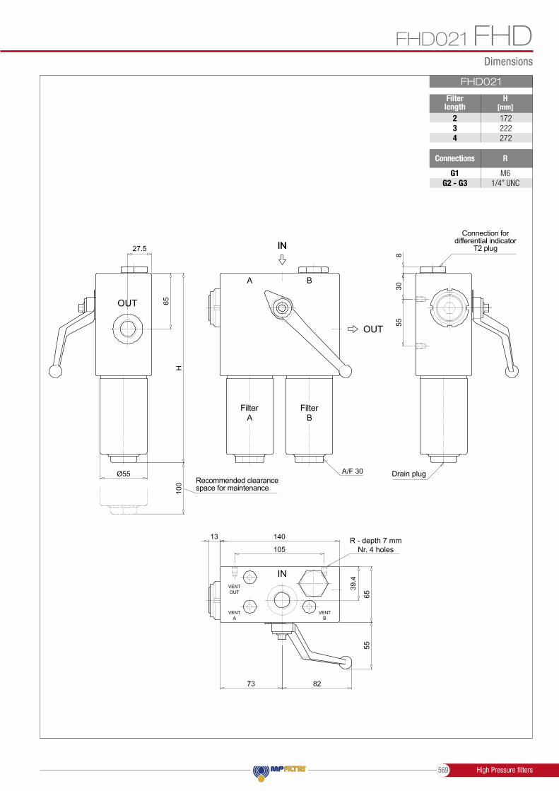
Dimensions
FHD021 FHDFHD021
H[mm]
234
172222272
Ø55
R
G1G2 - G3
M61/4” UNC
Filter length
Connections
OUT
OUT
IN
IN
VENTOUT
VENTA
VENTB
R - depth 7 mmNr. 4 holes
Drain plug
Connection for differential indicator
T2 plug
Recommended clearance space for maintenance
Filter Filter
High Pressure filters569

Designation & Ordering code
COMPLETE FILTER
FHD051 - FHD326 - FHD333FHD
Configuration example:
ExecutionP01Pxx
MP Filtri standardCustomized
HP320 A3 NM25 P01
SealsAV
NBRFPM
M25Axx
••
•••
Element ∆pNRS
20 bar20 bar
210 bar
Filtration rating
Element length12345
HP320HP050•••••
•••
Element series and size
HP050HP320
FHD333FHD326FHD051
•••
Series and size Configuration example: FHD326 A3 NG1S M25 P01FHD051 FHD326 FHD333
M25
M25
A16
A16
A25
A25
Wire mesh
Wire mesh
25 µm
25 µm
Inorganic microfiber
Inorganic microfiber
16 µm
16 µm
Inorganic microfiber
Inorganic microfiber
25 µm
25 µm
Filtration rating (filter media)
Filtration rating (filter media)
A03
A03
A10
A10
A06
A06
Inorganic microfiber
Inorganic microfiber
3 µm
3 µm
Inorganic microfiber
Inorganic microfiber
10 µm
10 µm
Inorganic microfiber
Inorganic microfiber
6 µm
6 µm
ConnectionsG1
G4G3
G6
F2
G2
G5
F1
G 3/4”
1/2” NPTG 1/2”
SAE 12 - 1 1/16” - 12 UN
-
3/4” NPT
SAE 8 - 3/4” - 16 UNF
-
G 1 1/4”-
SAE 20 - 1 5/8” - 12 UN
-
-
1 1/4” NPT
-
-
-
--
-
1 1/2” SAE 6000 psi/UNC
-
-
1 1/2” SAE 6000 psi/M
FILTER ELEMENT
Length12345
FHD333FHD326FHD051
FHD051 FHD326 FHD333
••••••
••••
ExecutionP01Pxx
MP Filtri standardCustomized
M25Axx
••
•••
Element ∆pNRS
20 bar20 bar
210 bar
Filtration rating
ValvesSB
Without bypassWith bypass 6 bar
SealsAV
NBRFPM
ACCESSORIES
Additional features page
T2 Plug 582
Differential indicators page page
DEA DLEElectrical differential indicator 577 Electrical / visual differential indicator 580
DLADEM
Electrical / visual differential indicator 579-580Electrical differential indicator 578-579 DVA
DTA
DVMVisual differential indicator 581 Electronic differential indicator
Visual differential indicator
581
581
DEH Hazardous area electronic differential indicator 577-578
High Pressure filters 570

Dimensions
FHD051 - FHD326 - FHD333 FHDFHD051
Filter length
H[mm]
2345
253295343465
Ø68
Connections R
G1G2G3
G4-G5-G6
M61/4” UNC
M61/4” UNC
Valves
SB
L[mm]168182.5
138152.5
M[mm]
L1[mm]
8498.5
OUT
OUT
IN
IN
VENTOUT
BALANCING
VENTA
VENTB
R - depth 7 mmNr. 4 holes
Connection for differential indicator
T2 plug
Recommended clearance space for maintenance
Filter Filter
Drain plug
High Pressure filters571

Dimensions
FHD051 - FHD326 - FHD333FHDFHD326
H[mm]
123
309432564
Ø101
R
G1G2 - G3
M103/8” UNC
Filter length
Connections
OUT
OUT
IN
IN
VENTOUT
BALANCING
VENTA
VENTB
R - depth 11 mmNr. 4 holes
Connection for differential indicator
T2 plug
Recommended clearance space for maintenance
Filter Filter
Drain plug
High Pressure filters 572

Dimensions
FHD051 - FHD326 - FHD333 FHDFHD333
H[mm]
23
479612
142
Ø101
R
F1F2
M103/8” UNC
Filter length
Connections
Length 2 - 3
OUT
OUT
IN
IN
VENTOUT
BALANCING
VENTA
VENTB
R - depth 11 mmNr. 4 holes
Connection for differential indicator
T2 plug
Recommended clearance space for maintenance
Filter Filter
Drain plug
High Pressure filters573

Dimensions
FHD051 - FHD326 - FHD333FHD
142
FHD333
R
F1F2
M103/8” UNC
Connections
Length 4
OUT
OUT
IN
IN
VENTOUT
BALANCING
VENTA
VENTB
R - depth 11 mmNr. 4 holes
Connection for differential indicator
T2 plug
Recommended clearance space for maintenance
Drain plug
Filter Filter
High Pressure filters 574

FHDSPARE PARTSOrder number for spare parts
Item:
Filter series
Seal Kit code numberFilterelement NBR FPM
Seeorder table
2Q.ty: 1 pc. Q.ty: 1 pc.Q.ty: 1 pc.
(3a ÷ 3g)3 4
Indicator connection plugNBR FPM
T2H T2V02050511 02050512FHD 0210205042002050377
0205042102050378
FHD 051FHD 326-333
FHD 021 - 051 - 326 - 333
3e
3b
3a
3b
3c
2
3d
4
3g
3f
3c
High Pressure fi lters575

High Pressure filters
Differential indicators
Suitable indicator types
Quick reference guide
Clogging indicators
Introduction
- Vacuum switches and gauges- Pressure switches and gauges- Differential pressure indicators
Filter elements are efficient only if their Dirt Holding Capacity is fully exploited.This is achieved by using filter housings equipped with clogging indicators.
These devices trip when the clogging of the filter element causes an increase in pressure drop across the filter element.
The indicator is set to alarm before the element becomes fully clogged.
MP Filtri can supply indicators of the following designs:
These type of devices can be provided with a visual, electrical or both signals.
The electronic model (only available for differential type indicators) with warning signals (75% of clogging) and alarm (clogging).
DIFFERENTIAL INDICATORS
Differential indicators are used on the Pressure line to check the efficiency of the filter element.They measure the pressure upstream and downstream of the filter element (differential pressure).Standard items are produced with special connection G 1/2” size.Also available in Stainless Steel models.
23
1
IN
OUT
IN
OUT
IN
OUT
IN
OUT
IN
OUT
IN
OUT
IN
OUT
IN
OUT
IN
OUT
IN
OUT
23
1
23
123
1
2
31
2
31
2
31
Filter seriesVisual
indicatorElectricalindicator
Electrical / Visualindicator
Electronicindicator
FMP 039 - 065 - 135 - 320FHP 010 - 011 - 065 - 135 - 350 - 500FMM 050 - 150FHA 051FHM 006 - 007 - 010 - 050 - 065 - 135 - 320 - 500FHB 050 - 135 - 320FHF 325FHD 021 - 051 - 326 - 333
With bypass valve
FMP 039 - 065 - 135 - 320FHP 010 - 011 - 065 - 135 - 350 - 500FMM 050 - 150FHA 051FHM 006 - 007 - 010 - 050 - 065 - 135 - 320 - 500FHB 050 - 135 - 320FHF 325FHD 021 - 051 - 326 - 333
Without bypass valve
DTA50xF70P01
DLA50xA51P01DLA50xA52P01DLA50xA71P01DLE50xA50P01DLE50xF50P01
DEH50xA48P01DEH50xA49P01DEH50xA70P01DEH70xA48P01DEH70xA49P01DEH70xA70P01
DVA50xP01DVM50xP01
DEA50xA50P01DEM50xAxxP01
DTA70xF70P01
DLA70xA51P01DLA70xA52P01DLA70xA71P01DLE70xA50P01DLE70xF50P01
DEH50xA48P01DEH50xA49P01DEH50xA70P01DEH70xA48P01DEH70xA49P01DEH70xA70P01
DVA70xP01DVM70xP01
DEA70xA50P01DEM70xAxxP01
NEWHazardous
area electronicindicator
High Pressure filters 576

Dimensions
DIFFERENTIAL INDICATORS
DE A 50 x A 50 P01DE A 70 x A 50 P01DE A 95 x A 50 P01
5.0 bar ±10%7.0 bar ±10%9.5 bar ±10%
Settings Ordering code
Electrical Differential Indicator
DEA*50 Materials- Body: Brass- Base: Black Nylon- Contacts: Silver- Seal: HNBR - FPM
Technical data- Max working pressure: 420 bar- Proof pressure: 630 bar- Burst pressure: 1260 bar- Working temperature: From -25 °C to +110 °C- Compatibility with fluids: Mineral oils, Synthetic fluids HFA, HFB, HFC according to ISO 2943- Degree protection: IP66 according to EN 60529 IP69K according to ISO 20653
Electrical data- Electrical connection: EN 175301-803- Resistive load: 0.2 A / 115 Vdc
1
2
3
1
2
3
1
2
3
1
2
3
4
5
1 2
Hydraulic symbol
Electrical symbol
3
2
1
3
2
1
3
1
2
5
44
505353
3
2
1
3
2
1
3
1
2
5
44
505353
A/F 30Max tighteningtorque: 65 N∙m
M20 x 1.5A/F 25
Max tighteningtorque: 50 N∙m
A/F 25Max tighteningtorque: 50 N∙m
min
. 110
min
. 110
8888
DE H 50 x A 48 P01DE H 70 x A 48 P01
5.0 bar ±10%7.0 bar ±10%
Settings Ordering code
Hazardous Area Electronic Differential Indicator
DEH*48 Materials- Body: AISI 316L- Contacts: Rhodium- Seal: FPM - MFQ
Technical data- Max working pressure: 420 bar- Proof pressure: 630 bar- Burst pressure: 1260 bar- Working temperature: From -60 °C to +125 °C- Compatibility with fluids: Mineral oils, Synthetic fluids HFA, HFB, HFC according to ISO 2943- Protection class: EX ia IIC T4/T6: Intrinsically safe- Temperature class: T4 (135 °C) and T6 (85 °C)- Degree of protection: IP 66/67/68 according to EN 60529- Connection type: Three-core cable - fitting M20x1.5 - Contact type: SPCO/SPDT (Hermetically sealed - Volt-free contacts)
Electrical data- Resistive Load: 830 mA / 24 Vdc - 180 mA / 110 Vac- Electrical Ratings: Ui = 30 Vdc li = 250 mA Pi = 1.3 W
Hydraulic symbol
Hydraulic symbol
Electrical symbol
Electrical symbol
Red
RedGreen
White
White
Black
Black1/2” NPT
DE H 50 x A 49 P01DE H 70 x A 49 P01
5.0 bar ±10%7.0 bar ±10%
Settings Ordering code
Hazardous Area Electronic Differential Indicator
DEH*49 Materials- Body: AISI 316L- Contacts: Rhodium- Seal: FPM - MFQ
Technical data- Max working pressure: 420 bar- Proof pressure: 630 bar- Burst pressure: 1260 bar- Working temperature: From -60 °C to +120 °C : ATEX, IECEx, EAC TR CU, INMETRO From -60 °C to +105 °C : UL/CSA- Compatibility with fluids: Mineral oils, Synthetic fluids HFA, HFB, HFC according to ISO 2943- Protection class: Ex d IIC T4/T6: Flameproof- Temperature class: T4 (135 °C) and T6 (85 °C)- Degree of protection: IP 66/67/68 according to EN 60529- Connection type: Four core-cable - fitting 1/2” NPT- Contact type: SPCO/SPDT (Hermetically sealed - Volt-free contacts)
Electrical data- Resistive Load: 830 mA / 24 Vdc - 180 mA / 110 Vac- Max voltage 150 Vac/dc- Power 20 W
- Certification / Approvals: ATEX, IECEx, EAC TR CU, INMETRO, UL/CSA Class I Division 1 Groups A-D, UL/CSA Class II Division 1 Groups E-G- Certification included as standard
- Certification / Approvals: ATEX, IECEx, EAC TR CU, INMETRO- Certification included as standard
flexib
le c
able
5
000
to A
flexib
le c
able
5
000
to A
High Pressure filters577

Dimensions
DIFFERENTIAL INDICATORS
DE M 50 x x 10 P01DE M 70 x x 10 P01DE M 95 x x 10 P01
5.0 bar ±10%7.0 bar ±10%9.5 bar ±10%
Settings Ordering code
Electrical Differential Indicator
DEM*10 Materials- Body: Brass- Base: Black Nylon- Contacts: Silver- Seal: HNBR - FPM
Technical data- Max working pressure: 420 bar- Proof pressure: 630 bar- Burst pressure: 1260 bar- Working temperature: From -25 °C to +110 °C- Compatibility with fluids: Mineral oils, Synthetic fluids HFA, HFB, HFC according to ISO 2943- Degree protection: IP66 according to EN 60529
Electrical data- Electrical connection: AMP Superseal series 1.5- Resistive load: 0.2 A / 115 Vdc- Switching type: Normally open contacts (NC on request)- Thermal lockout: Normally open up to 30 °C (option “F”)
1
2
3
1
2
3
1
2
3
1
2
3
4
5
1 2
Hydraulic symbol
Electrical symbol
1
2
1
2
1
2A
C
B
75
Thermal lockout
DE M 50 x x 20 P01DE M 70 x x 20 P01DE M 95 x x 20 P01
5.0 bar ±10%7.0 bar ±10%9.5 bar ±10%
Settings Ordering code
Electrical Differential Indicator
DEM*20 Materials- Body: Brass- Base: Black Nylon- Contacts: Silver- Seal: HNBR - FPM
Technical data- Max working pressure: 420 bar- Proof pressure: 630 bar- Burst pressure: 1260 bar- Working temperature: From -25 °C to +110 °C- Compatibility with fluids: Mineral oils, Synthetic fluids HFA, HFB, HFC according to ISO 2943- Degree protection: IP66 according to EN 60529
Electrical data- Electrical connection: AMP Time junior- Resistive load: 0.2 A / 115 Vdc- Switching type: Normally open contacts (NC on request)- Thermal lockout: Normally open up to 30 °C (option “F”)
1
2
3
1
2
3
1
2
3
1
2
3
4
5
1 2
Hydraulic symbol
Electrical symbol
1
2
1
2
1
2A
C
B
75
Thermal lockout
A/F 25Max tighteningtorque: 50 N∙m
63
Hydraulic symbol
Electrical symbol
- Certification / Approvals: ATEX, IECEx, EAC TR CU, INMETRO- Certification included as standard
DE H 50 x A 70 P01DE H 70 x A 70 P01
5.0 bar ±10%7.0 bar ±10%
Settings Ordering code
DEH*70Hazardous Area
Electronic Differential Indicator
Materials- Body: AISI 316L with internal engineered resin switch- Contacts: Rhodium- Seal: FPM - MFQ Technical data- Max working pressure: 420 bar- Proof pressure: 630 bar- Burst pressure: 1260 bar- Working temperature: From -60 °C to +80 °C- Compatibility with fluids: Mineral oils, Synthetic fluids HFA, HFB, HFC according to ISO 2943- Protection class: EX ia IIC T6: Intrinsically safe- Temperature class: T6 (85 °C)- Degree of protection: IP 66/67 according to EN 60529- Connection type: IEC 61076-2-101 D (M12) - Contact type: SPCO/SPDT (Hermetically sealed - Volt-free contacts)
Electrical data- Resistive Load: 830 mA / 24 Vdc - 180 mA / 110 Vdc- Electrical Ratings: Ui = 30 Vdc li = 250 mA Pi = 1.3 W
1
2
1
2
1
2A
C
B
75
A/F 28Max tighteningtorque: 65 N∙m
flexi
ble
cabl
e: 2
90 to
“A”
1
2
1
2
1
2A
C
B
75
A/F 28Max tighteningtorque: 65 N∙m
flexi
ble
cabl
e: 2
90 to
“A”
High Pressure filters 578

Dimensions
DIFFERENTIAL INDICATORS
DE M 50 x x 30 P01DE M 70 x x 30 P01DE M 95 x x 30 P01
5.0 bar ±10%7.0 bar ±10%9.5 bar ±10%
Settings Ordering code
1
2
1
2
1
2A
C
B
75
Electrical Differential Indicator
DEM*30 Materials- Body: Brass- Base: Black Nylon- Contacts: Silver- Seal: HNBR - FPM
Technical data- Max working pressure: 420 bar- Proof pressure: 630 bar- Burst pressure: 1260 bar- Working temperature: From -25 °C to +110 °C- Compatibility with fluids: Mineral oils, Synthetic fluids HFA, HFB, HFC according to ISO 2943- Degree protection: IP66 according to EN 60529
Electrical data- Electrical connection: Deutsch DT-04-2-P- Resistive load: 0.2 A / 115 Vdc- Switching type: Normally open contacts (NC on request)- Thermal lockout: Normally open up to 30 °C (option “F”)
1
2
3
1
2
3
1
2
3
1
2
3
4
5
1 2
Hydraulic symbol
Electrical symbol
1
2
1
2
1
2A
C
B75
A/F 28Max tighteningtorque: 65 N∙m
Thermal lockout
DE M 50 x x 35 P01DE M 70 x x 35 P01DE M 95 x x 35 P01
5.0 bar ±10%7.0 bar ±10%9.5 bar ±10%
Settings Ordering code
1
2
1
2
1
2A
C
B
75
Electrical Differential Indicator
DEM*35 Materials- Body: Brass- Base: Black Nylon- Contacts: Silver- Seal: HNBR - FPM
Technical data- Max working pressure: 420 bar- Proof pressure: 630 bar- Burst pressure: 1260 bar- Working temperature: From -25 °C to +110 °C- Compatibility with fluids: Mineral oils, Synthetic fluids HFA, HFB, HFC according to ISO 2943- Degree protection: IP66 according to EN 60529
Electrical data- Electrical connection: Deutsch DT-04-3-P- Resistive load: 0.2 A / 115 Vdc- Switching type: SPDT contact- Thermal lockout: Normally open up to 30 °C (option “F”)
1
2
3
1
2
3
1
2
3
1
2
3
4
5
1 2
Hydraulic symbol
Electrical symbol
1
2
1
2
1
2A
C
B
75
A/F 28Max tighteningtorque: 65 N∙m
flexi
ble
cabl
e: 2
40 to
“A”
Thermal lockout
DL A 50 x A xx P01DL A 70 x A xx P01DL A 95 x A xx P01
5.0 bar ±10%7.0 bar ±10%9.5 bar ±10%
Settings Ordering code
3
2
1
3
2
1
3
1
2
5
44
505353
Electrical/Visual Differential Indicator
DLA*51 - DLA*52 Materials- Body: Brass- Base: Transparent Nylon- Contacts: Silver- Seal: HNBR - FPM
Technical data- Max working pressure: 420 bar- Proof pressure: 630 bar- Burst pressure: 1260 bar- Working temperature: From -25 °C to +110 °C- Compatibility with fluids: Mineral oils, Synthetic fluids HFA, HFB, HFC according to ISO 2943- Degree protection: IP66 according to EN 60529 IP69K according to ISO 20653
Electrical data- Electrical connection: EN 175301-803- Type 51 52 - Lamps 24 Vdc 110 Vdc - Resistive load: 1 A / 24 Vdc 1 A / 110 Vdc
1
2
3
1
2
3
1
2
3
1
2
3
4
5
1 2
Hydraulic symbol
Electrical symbol
3
2
1
3
2
1
3
1
2
5
44
505353
A/F 30Max tighteningtorque: 65 N∙m
GREENLAMP
REDLAMP
High Pressure filters579

Dimensions
DIFFERENTIAL INDICATORS
DL E 50 x A 50 P01DL E 70 x A 50 P01DL E 95 x A 50 P01
5.0 bar ±10%7.0 bar ±10%9.5 bar ±10%
Settings Ordering code
Electrical/Visual Differential Indicator
DLE*A50 Materials- Body: Brass- Base: Black Nylon- Contacts: Silver- Seal: HNBR - FPM
Technical data- Max working pressure: 420 bar- Proof pressure: 630 bar- Burst pressure: 1260 bar- Working temperature: From -25 °C to +110 °C- Compatibility with fluids: Mineral oils, Synthetic fluids HFA, HFB, HFC according to ISO 2943- Degree protection: IP65 according to EN 60529
Electrical data- Electrical connections: EN 175301-803- Resistive load: 5 A / 250 Vac- Available the connector with lamps
Hydraulic symbol
Electrical symbol
1
2
3
1
2
358
58
58
59
1
2
3
1
2
3
1
2
3
1
2
3
4
5
1 2
1
2
3
1
2
3
58
58
58
59
A/F 32Max tighteningtorque: 95 N∙m
DL E 50 x F 50 P01DL E 70 x F 50 P01DL E 95 x F 50 P01
5.0 bar ±10%7.0 bar ±10%9.5 bar ±10%
Settings Ordering code
Electrical/Visual Differential Indicator
DLE*F50 Materials- Body: Brass- Base: Black Nylon- Contacts: Silver- Seal: HNBR - FPM
Technical data- Max working pressure: 420 bar- Proof pressure: 630 bar- Burst pressure: 1260 bar- Working temperature: From -25 °C to +110 °C- Compatibility with fluids: Mineral oils, Synthetic fluids HFA, HFB, HFC according to ISO 2943- Degree protection: IP65 according to EN 60529
Electrical data- Electrical connections: EN 175301-803- Resistive load: 5 A / 250 Vac- Thermal lockout setting: +30 °C
Hydraulic symbol
Electrical symbol
1
2
3
1
2
3
58
58
58
59
1
2
3
1
2
3
1
2
3
1
2
3
4
5
1 2
1
2
3
1
2
3
58
58
58
59
A/F 32Max tighteningtorque: 95 N∙m
Thermal lockout
DL A 50 x A 71 P01DL A 70 x A 71 P01DL A 95 x A 71 P01
5.0 bar ±10%7.0 bar ±10%9.5 bar ±10%
Settings Ordering code
Electrical/Visual Differential Indicator
DLA*71 Materials- Body: Brass- Base: Black Nylon- Contacts: Silver- Seal: HNBR - FPM
Technical data- Max working pressure: 420 bar- Proof pressure: 630 bar- Burst pressure: 1260 bar- Working temperature: From -25 °C to +110 °C- Compatibility with fluids: Mineral oils, Synthetic fluids HFA, HFB, HFC according to ISO 2943- Degree protection: IP65 according to EN 60529 IP69K according to ISO 20653
Electrical data- Electrical connection: IEC 61076-2-101 D (M12)- Lamps 24 Vdc- Resistive load: 0.4 A / 24 Vdc
Hydraulic symbol
Electrical symbol
3
2
1
3
2
1
3
1
2
5
44
505353
1
2
3
1
2
3
1
2
3
1
2
3
4
5
1 2
3
2
1
3
2
1
3
1
2
5
44
505353
A/F 30Max tighteningtorque: 65 N∙m
GREENLAMP
REDLAMP
High Pressure filters 580

Dimensions
DIFFERENTIAL INDICATORS
DT A 50 x x 70 P01DT A 70 x x 70 P01DT A 95 x x 70 P01
5.0 bar ±10%7.0 bar ±10%9.5 bar ±10%
Settings Ordering code
DV A 50 x P01DV A 70 x P01DV A 95 x P01
5.0 bar ±10%7.0 bar ±10%9.5 bar ±10%
Settings Ordering code
DV M 50 x P01DV M 70 x P01DV M 95 x P01
5.0 bar ±10%7.0 bar ±10%9.5 bar ±10%
Settings Ordering code
Electronic Differential Indicator
Visual Differential Indicator
Visual Differential Indicator
DTA*70
DVA
DVM
Materials- Body: Brass- Internal parts: Brass - Nylon- Contacts: Silver- Seal: HNBR - FPM
Technical data- Max working pressure: 420 bar- Proof pressure: 630 bar- Burst pressure: 1260 bar- Compatibility with fluids: Mineral oils, Synthetic fluids HFA, HFB, HFC according to ISO 2943- Degree protection: IP67 according to EN 60529
Electrical data- Electrical connection: IEC 61076-2-101 D (M12)- Power supply: 24 Vdc- Analogue output: From 4 to 20 mA- Thermal lockout: 30 °C (all output signals stalled up to 30 °C)
Materials- Body: Brass- Internal parts: Brass - Nylon- Contacts: Silver- Seal: HNBR - FPM
Technical data- Reset: Automatic reset- Max working pressure: 420 bar- Proof pressure: 630 bar- Burst pressure: 1260 bar- Working temperature: From -25 °C to +110 °C- Compatibility with fluids: Mineral oils, Synthetic fluids HFA, HFB, HFC according to ISO 2943- Degree protection: IP65 according to EN 60529
Materials- Body: Brass- Internal parts: Brass - Nylon- Contacts: Silver- Seal: HNBR - FPM
Technical data- Reset: Manual reset- Max working pressure: 420 bar- Proof pressure: 630 bar- Burst pressure: 1260 bar- Working temperature: From -25 °C to +110 °C- Compatibility with fluids: Mineral oils, Synthetic fluids HFA, HFB, HFC according to ISO 2943- Degree protection: IP65 according to EN 60529
Hydraulic symbol
Hydraulic symbol
Hydraulic symbol
Electrical symbol
3
4
2
5
1 +24 Vdc
4 20 mA
75% - N.O.
100% - N.O.
0 Vdc
÷
47
39 34
1
2
3
1
2
3
1
2
3
1
2
3
4
5
1 2
1
2
3
1
2
3
1
2
3
1
2
3
4
5
1 2
1
2
3
1
2
3
1
2
3
1
2
3
4
5
1 2
3
4
2
5
1 +24 Vdc
4 20 mA
75% - N.O.
100% - N.O.
0 Vdc
÷
47
39 34
3
4
2
5
1 +24 Vdc
4 20 mA
75% - N.O.
100% - N.O.
0 Vdc
÷
47
39 34
3
4
2
5
1 +24 Vdc
4 20 mA
75% - N.O.
100% - N.O.
0 Vdc
÷
47
39 34
A/F 30Max tighteningtorque: 50 N∙m
A/F 28Max tighteningtorque: 65 N∙m
A/F 30Max tighteningtorque: 65 N∙m
Green / Redclogging indicator
Redclogging indicator
Digital output
Digital output
Industry 4.0 READY
High Pressure filters581

Dimensions
DIFFERENTIAL INDICATORS
T2 HT2 V
HNBRFPM
Seal Ordering code
Indicator plug
T2 Materials- Body: Phosphatized steel- Seal: HNBR / FPM
10A
/F30
A/F 30Max tighteningtorque: 50 N∙m
High Pressure filters 582

DIFFERENTIAL INDICATORS
Series
Series
DE
T2
DL
DVDT
OptionP01Pxx
MP Filtri standardCustomized
Configuration example 1: DE HM 50F50 P01
Configuration example T2 H
Configuration example 3: DL VE 71A70 P01Configuration example 4: DT HA 70F50 P01
Configuration example 5: DV VM 95 P01
Configuration example 2: DE FH 70A50 P01
TypeA A
EH
M M
Pressure setting507095
5 bar7 bar9.5 bar
Standard type With automatic reset
Electrical or Electronic differential indicator
Indicator plug
For high power supplyHazardous area
Electronic differential indicator
With wired electrical connection With manual reset
Electrical / Visual differential indicator
Visual differential indicator
DESIGNATION & ORDERING CODE - DIFFERENTIAL INDICATORS
DESIGNATION & ORDERING CODE - DIFFERENTIAL INDICATOR PLUG
Seals
Seals
F
H
HV
V
MFQ
HNBR
HNBRFPM
FPM
••
••
• •
Electrical connections
2010
30
50
48
52
35
51
49
7071
DL
DLE
DLE
DLE
DLE
DEH
DEH
DEH
DEA
DEA
DEA
DEHDEA
DE DT
DT
DT
DT
DT
DEM
DEM
DEM
DEM
DV
DV
DV
DV
DV
DLA
DLA
DLA
DLA
•
•• • • • • ••• • • • • •
• • • • • •
•• • • • • •
•• • • • • •
•
•
•
••••
•
•
•
••
•
• • •
ThermostatAF
WithoutWith thermostat
Connection Deutsch DT-04-2-PConnection AMP Timer JuniorConnection AMP Superseal series 1.5
Connection Deutsch DT-04-3-P
Connection EN 175301-803
Connection via three-core cable - fitting M20x1.5
Connection EN 175301-803, transparent base with lamps 110 VdcConnection EN 175301-803, transparent base with lamps 24 Vdc
Connection via four-core cable - fitting 1/2” NPT
Connection IEC 61076-2-101 D (M12)Connection IEC 61076-2-101 D (M12), black base with lamps 24 Vdc
Designation & Ordering code
••
•
•
High Pressure filters583

Clogging indicators are devices that check the life time of the filter elements.They measure the pressure drop through the filter element directly connected to the filter housing.These devices trip when the clogging of the filter element causes a pressure drop increasing across the filter element.Filter elements are efficient only if their Dirt Holding Capacity is fully exploited.This is achieved by using filter housings equipped with clogging indicators.The indicator is set to alarm before the element becomes fully clogged.
MP Filtri can supply indicators of the following designs: - Vacuum switches and gauges - Pressure switches and gauges - Differential pressure indicators
These type of devices can be provided with a visual, electrical or both signals.The electronic differential pressure clogging indicator is also available. It provides both analogical 4-20 mA output and digital warning (75% of clogging) and alarm (clogging) outputs.
Clogging Indicators 646

Clogging Indicators
Clogging Indicators647

Clogging indicators
Clogging indicators
Suitable indicator types
BAROMETRIC INDICATORSPressure indicators are used on the Return line to check the effi ciency of the fi lter element.They measure the pressure upstream of the fi lter element.Standard items are produced with R 1/8” EN 10226 connection.
23
1
IN
OUT
IN
OUT
IN
OUT
IN
OUT
IN
OUT
IN
OUT
IN
OUT
IN
OUT
IN
OUT
IN
OUT
23
1
23
123
1
2
31
2
31
2
31
DIFFERENTIAL INDICATORSDifferential indicators are used on the Pressure line to check the effi ciency of the fi lter element.They measure the pressure upstream and downstream of the fi lter element (differential pressure).Standard items are produced with special connection G 1/2” size.Also available in Stainless Steel models.
23
1
IN
OUT
IN
OUT
IN
OUT
IN
OUT
IN
OUT
IN
OUT
IN
OUT
IN
OUT
IN
OUT
IN
OUT
23
1
23
123
1
2
31
2
31
2
31
VACUUM INDICATORSVacuum indicators are used on the Suction line to check the effi ciency of the fi lter element.They measure the pressure downstream of the fi lter element.Standard items are produced with R 1/4” EN 10226 connection.Available products with R 1/8” EN 10226 to be fi tted on MPS series.
23
1
IN
OUT
IN
OUT
IN
OUT
IN
OUT
IN
OUT
IN
OUT
IN
OUT
IN
OUT
IN
OUT
IN
OUT
23
1
23
123
1
2
31
2
31
2
31
Clogging Indicators 648

QUICK REFERENCE GUIDE CLOGGING INDICATORS
Filter series
Filter family
RE
TU
RN
FIL
TE
RS
RE
TU
RN
/ S
UC
TIO
N
FIL
TE
RS
SP
IN-O
N
FIL
TE
RS
SU
CTIO
N
FIL
TE
RS
Electronicindicator
Visualindicator
Electrical / Visualindicator
Electricalindicator
SF2 250 - 350SF2 500 - 501 - 503 - 504 - 505SF2 510 - 535 - 540
MPLXFRI 025 - 040 - 100 - 250 - 630 - 850
MPFX-MPTX-MPF-MPT - bypass 1.75 barMPH - bypass 1.75 barRF2250 - RF2350 - bypass 1.75 bar
MPFX-MPTX-MPF-MPT - bypass 3 barMPH - bypass 2.5 barFRI 255RF2250 - RF2350 - bypass 3 bar
MRSX 116 - 165 - 166Suctionline
MPS 050 - 070 - 100 - 150MPS 200 - 250 - 300 - 350
Suctionline
MPS 050 - 070 - 100 - 150MPS 200 - 250 - 300 - 350
Returnline
DTA20xF70P01
DTA12xA70P01
DTA12xF70P01
DTA20xA70P01
DTA20xF70P01
MPS 051 - 071 - 101 - 151MPS 301 - 351MSH 050 - 070 - 100 - 150
In-line
MRSX 116 - 165 - 166LMP 124 MULTIPORT
Returnline
SFEX060-080-110-160
VLA21AA51P01
VLA21AA52P01
VLA21AA53P01
VLA21AA71P01
DLA20xA51P01
DLA20xA52P01
DLA20xA71P01
DLE20xA50P01
DLE20xF50P01
BLA15HA51P01
BLA15HA52P01
BLA15HA53P01
BLA15HA71P01
BLA20HA51P01
BLA20HA52P01
BLA20HA53P01
BLA20HA71P01
VLB21AA51P01
VLB21AA52P01
VLB21AA53P01
VLB21AA71P01
VLB21AA51P01
VLB21AA52P01
VLB21AA53P01
VLB21AA71P01
BLA15HA51P01
BLA15HA52P01
BLA15HA53P01
BLA15HA71P01
DLA12xA51P01
DLA12xA52P01
DLA12xA71P01
DLE12xA50P01
DLE12xF50P01
DLE20xF50P01
DLE20xF50P01
BLA25HA51P01
BLA25HA52P01
BLA25HA53P01
BLA25HA71P01
VLB21AA51P01
VLB21AA52P01
VLB21AA53P01
VLB21AA71P01
BLA15HA51P01
BLA15HA52P01
BLA15HA53P01
BLA15HA71P01
BLA20HA51P01
BLA20HA52P01
BLA20HA53P01
BLA20HA71P01
VEA21AA50P01
DEA20xA50P01
DEM20xA10P01
DEM20xA20P01
DEM20xA30P01
DEM20xA35P01
BEA15HA50P01
BEM15HA41P01
BEA20HA50P01
BEM20HA41P01
VEB21AA50P01
VEB21AA50P01
BEA15HA50P01
BEM15HA41P01
DEA12xA50P01
DEM12xAxxP01
BEA25HA50P01
BEM25HA41P01
BET25HF10P01
BET25HF30P01
BET25HF50P01
VEB21AA50P01
BEA20HA50P01
BEM20HA41P01
BEA15HA50P01
BEM15HA41P01
VVA16P01
VVR16P01
DVA20xP01
DVM20xP01
BVA14P01
BVR14P01
BVP15HP01
BVQ15HP01
BVA25P01
BVR25P01
BVP20HP01
BVQ20HP01
VVB16P01
VVS16P01
VVB16P01
VVS16P01
BVA14P01
BVR14P01
BVP20HP01
BVQ20HP01
DVA12xP01
DVM12xP01
BVA25P01
BVR25P01
BVP20HP01
BVQ20HP01
VVB16P01
VVS16P01
BVA14P01
BVR14P01
BVP15HP01
BVQ15HP01
BVA25P01
BVR25P01
BVP20HP01
BVQ20HP01
RFEX060-080-110-160
RFEX060-080-110-160
With bypass valve
With bypass valve
With bypass valve
Without bypass valve
Clogging Indicators649

QUICK REFERENCE GUIDECLOGGING INDICATORS
Filter series
Filter family
LO
W &
ME
DIU
MP
RE
SS
UR
E F
ILTE
RS
HIG
H P
RE
SS
UR
EFIL
TE
RS
STA
INLE
SS
STE
EL
HIG
H P
RE
SS
UR
E F
ILTE
RS
LMP 110 - 112 - 116 - 118 - 119 MULTIPORTLMP 120 - 122 - 123 MULTIPORTLMP 210 - 211 - LDPLMP 400 - 401 & 430 - 431LMP 900 - 901LMP 902 - 903LMP 950 - 951LMP 952 - 953 - 954LMD 211 - 400 - 401 - 431 - 951 - LDD
With bypass valve
DTA20xF70P01DVA20xP01
DVM20xP01
DLA20xA51P01
DLA20xA52P01
DLA20xA71P01
DLE20xA50P01
DLE20xF50P01
LMP 110 - 112 - 116 - 118 - 119 MULTIPORTLMP 120 - 122 - 123 MULTIPORTLMP 210 - 211 - LDPLMP 400 - 401 & 430 - 431LMP 900 - 901LMP 902 - 903LMP 950 - 951LMP 952 - 953 - 954LMD 211 - 400 - 401 - 431 - 951 - LDD
Without bypass valve
DTA50xF70P01DVA50xP01
DVM50xP01
DLA50xA51P01
DLA50xA52P01
DLA50xA71P01
DLE50xA50P01
DLE50xF50P01
DTA50xF70P01
FMP 039 - 065 - 135 - 320FHP 010 - 011 - 065 - 135 - 350 - 500FMM 050 - 150FHA 051FHM 006 - 007 - 010 - 050 - 065 - 135 - 320 - 500FHB 050 - 065 - 135 - 320FHF 325FHD 021 - 051 - 326 - 333
With bypass valve
DVA50xP01
DVM50xP01
DLA50xA51P01
DLA50xA52P01
DLA50xA71P01
DLE50xA50P01
DLE50xF50P01
DEH50xA48P01
DEH50xA49P01
DEH50xA70P01
DEH70xA48P01
DEH70xA49P01
DEH70xA70P01
DTA70xF70P01
DTA95xF70P01
FMP 039 - 065 - 135 - 320FHP 010 - 011 - 065 - 135 - 350 - 500FMM 050 - 150FHA 051FHM 006 - 007 - 010 - 050 - 065 - 135 - 320 - 500FHB 050 - 065 - 135 - 320FHF 325FHD 021 - 051 - 326 - 333
Without bypass valve
DVA70xP01
DVM70xP01
DVA95xP01
DVM95xP01
DLA70xA51P01
DLA70xA52P01
DLA70xA71P01
DLE70xA50P01
DLE70xF50P01
DLA95xA51P01
DLA95xA52P01
DLE95xA50P01
DLE95xF50P01
DEH50xA48P01
DEH50xA49P01
DEH50xA70P01
DEH70xA48P01
DEH70xA49P01
DEH70xA70P01
DVX50xP01
DVY50xP01
FZH 010 - 011 - 039FZP 039 - 136FZX 011FZB 039FZM 039FZD 051
With bypass valve
DLX50xA51P01
DLX50xA52P01
DEH50xA48P01
DEH50xA49P01
DEH50xA70P01
DEH70xA48P01
DEH70xA49P01
DEH70xA70P01
DVX70xP01
DVY70xP01
DVX95xP01
DVY95xP01
FZH 010 - 011 - 039FZP 039 - 136FZB 039FZM 039FZD 010 - 021 - 051
Without bypass valve
DLX70xA51P01
DLX70xA52P01
DLX95xA51P01
DEH50xA48P01
DEH50xA49P01
DEH50xA70P01
DEH70xA48P01
DEH70xA49P01
DEH70xA70P01
Hazardous area electronic
indicatorElectronicindicator
Visualindicator
Electrical / Visualindicator
Electricalindicator
DVS25HP01
DVS40HP01
DVS25HP01
DVS40HP01
DEA20xA50P01
DEM20xAxxP01
DEA50xA50P01
DEM50xAxxP01
DEA50xA50P01
DEM50xAxxP01
DEA70xA50P01
DEM70xAxxP01
DEA95xA50P01
DEM95xAxxP01
DEX50xA50P01
DEX70xA50P01
DEX95xA50P01
DES25HA10P01
DES25HA30P01
DES25HA80P01
DES40HA10P01
DES40HA30P01
DES40HA80P01
LFEX060-080-110-160
With bypass valve
Without bypass valve LFEX060-080-110-160
Clogging Indicators 650

NOTES
Clogging Indicators651

NOTES
656

All data, details and words contained in this publication are provided for information purposes only.MP Filtri reserves the right to make modifications to the models and versions of the described products at any time
for both technical and / or commercial reasons.The colors and the pictures of the products are purely indicative.
Any reproduction, partial or total, of this document is strictly forbidden.All rights are strictly reserved.

EN
- R
ev. 0
3-20
21C
MP
EN
001G
mpfiltri.com
WORLDWIDE
TO PERFORM
NETWORK
PASSION
HEADQUARTERS
ITALFILTRI LLCMoscow - Russia+7 (495) 220 94 60 [email protected]
MP Filtri Canada Inc.Concord, Ontario - Canada+1 905 303 [email protected]
MP Filtri France SASVilleneuve la GarenneFrance+33 (0)1 40 86 47 [email protected]
MP Filtri Germany GmbHSt. Ingbert - Germany+49 (0) 6894 [email protected]
MP Filtri India Pvt. Ltd.Bangalore - India+91 80 4147 7444 / +91 80 4146 [email protected]
MP Filtri (Shanghai) Co., Ltd.Shanghai - Minhang District - China+86 21 58919916 [email protected]
MP Filtri U.K. Ltd.Bourton on the WaterGloucestershire - United Kingdom+44 (0) 1451 822 522 [email protected]
MP Filtri U.S.A. Inc.Quakertown, PA - U.S.A.+1 215 529 [email protected]
BRANCH OFFICES
MP Filtri S.p.A.Pessano con BornagoMilano - Italy+39 02 [email protected]