HYDRAULIC EXCAVATOR...HYDRAULIC EXCAVATOR SERIAL NUMBERS PCl28UU-1 - 2347 andup This material is...
238
Operation & Maintenance Manual SEAM023300 PC1 28Uh HYDRAULIC EXCAVATOR SERIAL NUMBERS PCl28UU-1 - 2347 andup This material is proprietary to Komatsu America International Company and is not to be reproduced, used, or disclosed except in accordance with written authorization from Komatsu America International Company. It is our policy to improve our products whenever it is possible and practical to do so. We reserve the right to make changes or add improvements at any time without incurring any obligation to install such changes on products sold previously. Due to this continuous program of research and development, periodic revisions may be made to this publication. It is recommended that customers contact their distributor for information on the latest revision. October 1998 Copyright 1998 Komatsu America International Company https://tractormanualz.com
Transcript of HYDRAULIC EXCAVATOR...HYDRAULIC EXCAVATOR SERIAL NUMBERS PCl28UU-1 - 2347 andup This material is...

Operation & Maintenance Manual
SEAM023300
PC1 28Uh HYDRAULIC EXCAVATOR
SERIAL NUMBERS PCl28UU-1 - 2347 andup This material is proprietary to Komatsu America International Company and is not to be reproduced, used, or disclosed except in accordance with written authorization from Komatsu America International Company.
It is our policy to improve our products whenever it is possible and practical to do so. We reserve the right to make changes or add improvements at any time without incurring any obligation to install such changes on products sold previously.
Due to this continuous program of research and development, periodic revisions may be made to this publication. It is recommended that customers contact their distributor for information on the latest revision.
October 1998 Copyright 1998 Komatsu America International Company
https://tractormanualz.com

A WARNING
Unsafe use of this machine may cause serious injury or death. Operators and maintenance personnel must read this manual before operating or maintaining this machine. This manual should be kept near the machine for reference and periodically reviewed by all personnel who come in contact with it.
CALIFORNIA
Proposition 65 Warning
Diesel engine exhaust and some of its constituents are known to the State of California to cause cancer, birth defects and other reproductive harm.
https://tractormanualz.com

1. INTRODUCTION
This manual is a guidebook and has been written so that you may use this equipment safely and effectively.
Please read this manual and thoroughly understand it prior to operating, inspecting or servicing this equipment. Not following the contents of this manual may lead to incidents which cause serious injury.
AWarning!
0
l
0
l
0
l
l
0
l
8
Improper operation and maintenance of this equipment may lead to serious injury or death.
Operators and maintenance personnel should read this manual thoroughly prior to operating or servicing this equipment.
This manual should be kept in a place close to the equipment so thet it may be referred to easily. All personnel handling this equipment should read it periodically.
Do not use this equipment until you are thoroughly familiar with the contents of this manual.
Always have this manual available nearby and read it repeatedly.
If you lose this manual or if it is soiled or damaged so that it cannot be used, immediately 0rder.a replacement manual from Kometsu or your Komatsu dealer.
If you~seil this equipment to some other party, be sure to give this manual to the new owner.
Komatsu provides machines that comply with all applicable regulations and standards of the countries to which they have been shipped. If the machine that you purchased was purchased in a different country ‘or from a person or company from another country, it may lack certain safety devices and specifications that are necessary for use in your country.. If there are any questions whether your product complies with the standards and regulations which apply in your country, consult Komatsu or your Komatsu dealer.
Continuing improvements in this equipment can lead to specific changes which may not be reflected in the contents of this manual. Consult Komatsu or your Komatsu dealer for anything which may be unclear.
Information on safety is expiained in Safety Information on page O-2 and in the items concerning safety throughout the manual from page l-1.
CALIFORNIA
Proposition 65 Warning Diesel engine exhaust and some of its
constihtents are known to the State
of California to cause cancer, birth
defects, and other reproductive
harm.
o-1
https://tractormanualz.com

2. SAFETY INFORMATION
Most accidents are caused by failing to follow basic safety rules while operating, inspecting or servicing equipment. Please read and take note of ail precautions and safety rules written in this , manual or on the equipment itself and thoroughly understand them prior to operating, inspecting, or servicing this equipment.
Do not operate, inspect or service this equipment under any circumstances until you understand these precautions.
The following safety warnings are distinguished in this manual and on labels on the equipment to aid in their understanding.
a DANGER!
A WARNING!
A CAUTION
NOTICE
This word of warning is used when there is a high probability of serious injury or death if the danger is not avoided. This is used in safety warning messages in the manual and on safety labels on the machine. These warnings usually describe precautions that must be taken to avoid the hazard.
This word of warning is used when there is a potentially dangerous situation which could result in serious injury or deeth if the hmard is not avoided. This is also used in safety warning messages in the manual and on safety labels on the machine. These warnings usually describe precautions that must be taken to avoid the hazard.
This is used to indicate a situation where injury or serious damage to the machine could occur if the hazard cannot be avoided.
This indicates that damage to the machine or shortening the life of the machine could occur if the instruction is not followed.
Safety items are explained from page 1-l .
Komatsu cannot predict every circumstance that might involve a potential hazard in operating, inspecting and servicing this machine. Therefore, the precautions and warnings in this manual and written on the machine may not include ail possible safety precautions. if you operate, inspect or service this equipment in a manner not dealt with in this manual you should consider necessary safety considerations to be entirely your own responsibility.
O-2
https://tractormanualz.com

3. OVERVIEW OF THE EQUIPMENT
3.1 DESIGNATED USES
This machine is designed to be used for the following work: l Excavation l Digging ditches l Grading 0 Loading l Digging side ditches
Please see section 13.12 under operations entitled “Work Possible using the Hydraulic Shovel” for further details concerning possible operations.
3.2 FEATURES OF THIS MACHINE
0 It is equipped with various controls based on advanced electronics systems. 0 Accident prevention device
It has a device which stops operation and sounds a warning when the bucket approaches the cab. Please read the precautions in the safety section and use the machine properly.
o Arm and boom apparatus automatic stop device It has an automatic controIier which indicates excavating depth, can designate the amount the boom is to be lowered, can designate how much it can be raised and the left offset position. Please refer to section 13.19 “Handling 4 systems” for operation.
0 Daily inspection and breakdown diagnosis with the monitor panel. o Digging power and lifting power can be varied by a simple command (optional).
(Please refer to the operations section for details.) 0 Low noise’operation and attractive design and coloring make possible operation with minimaf
disturbance in residential settings l High operating performance due to powerful engine and high performance hydraulic pumps.
o-3
https://tractormanualz.com

3. OVERVIEW OF THE EQUIPMENT
3.3 BREAK-IN
Your Komatsu machine has been thoroughly calibrated and tested prior to shipment. However, if you initially operate the equipment improperly or subject it to undue stress, performance will rapidly decline and this will shorten the life of the machine. Therefore, be sure to break in the machine for the initial 100 hours (as indicated on the service meter). Break in the machine by paying particular attention to the following items. 3 Idle the engine for 5 minutes after starting and operate it with a warm engine. 0 Avoid operating with heavy loads or at high speeds. 0 Avoid abrupt movements, sudden acceleration, unnecessary sudden stops and sudden changes
of direction. The precautions indicated in this manual for operation, maintenance and safety are only for when
the equipment is used for the designated purposes. If you operate, inspect or service this equipment in a manner not dealt with in this manual you should consider necessary safety considerations to be entirely your own responsibility.
Nonetheless, operations that are proscribed in this manual should not be performed under any circumstances.
o-4
https://tractormanualz.com
5. LOCATION OF SERIAL NUMBER PLAYES, AND FORM TO ENTER SERIAL NUMBER AND NAME OF THE DISTRIBUTOR
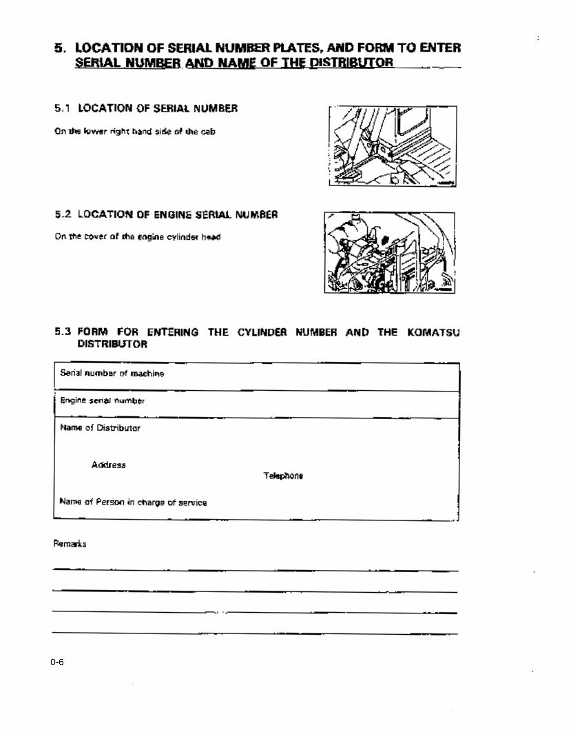
5.1 LOCATION OF SERIAL NUMBER
On the lower right hand side of the cab
1 , 5.2 LOCATION OF ENGINE SERIAL NUMBER
On the cover of the engine cylinder head
Ir H I
FORM FOR ENTERING THE CYLINDER NUMBER AND THE KOMATSU 5.3 DISTRIBUTOR
Serial number of machine
Engine serial number
Name of Distributor
Address
Name of Person in charge of service
Telephone
Remarks
O-6
https://tractormanualz.com

6. TABLE OF CONTENTS
1. Introduction ........................................................................................................................................ o- 1 2. Safety information ............................................................................................................................ o- 2 3. Overview of the equipment ............................................................................................................. o- 3 4. Memo ................................................................................................................................................. o- 5 5. Location of serial number plates,
and form to enter serial number and name of the distributor ....................................... 0- 6
Safety
7. Basic Precautions .............................................................................................................................. I- 2 8. Precautions for operating ................................................................................................................. I- 7
8.1 Before starting the engine ...................................................................................................... I- 7 8.2 After starting the engine ......................................................................................................... I- 9 8.3 Transport the vehicle ............................................................................................................... 1-14 8.4 Battery ....................................................................................................................................... l-15 8.5 Towing ...................................................................................................................................... 1-16 8.6 Precautions for hoisting operations ....................................................................................... 1-17
9. Precautions for maintenance ........................................................................................................... I-18 9.1 Prior to performing maintenance .......................................................................................... I-18 9.2 During maintenance ..................................................................... . .......................................... l-21
10. Where safety labels have been attached ....................................................................................... 1-25 10.1 Where safety labels are located.. ........................................................................................... 1-25
Operation
11. The name of each part ..................................................................................................................... 2- 2 11.1 General view of the vehicle.__ ................................................................................................. 2- 2 11.2 General view of controls and gauges ................................................................................... 2- 3
12. Explanation of each device . . . . . . . . . . . . . . . . . . . . . . . . . . . . . . . . . . . . . . . . . . . . . . . . . . . . . . . . . . . . . . . . . . . . . . . . . . . . . . . . . . . . . . . . . . . . . . . . . . . . . . . . . . . . . . 2- 4 12.1 12.2 12.3 12.4 12.5 12.6 12.7 12.8 12.9 12.10 12.11 12.12 12.13 12.14 12.15 12.16 12.17 12.18
Vehicle monitor panel . . . . . . . . . . . . . . . . . . . . . . . . . . . . . . . . . . . . . . . . . . . . . . . . . . . . . . . . . . . . . . . . . . . . . . . . . . . . . . . . . . . . . . . . . . . . . . . . . . . . . . . . . . . . . Switches .................................................................................................................................... Control levers/pedals ............................................................................................................... Engine food .............................................................................................................................. Front window ........................................................................................................................... Sliding door .............................................................................................................................. Hammer for emergency escape ............................................................................................. Fuse box ................................................................................................................................... Fusible link ................................................................................................................................ Locking cap and covers .......................................................................................................... Manual pocket .......................................................................................................................... Tool box .................................................................................................................................... Grease gun holder ................................................................................................................... Controllers ................................................................................................................................ Ashtray (if equipped) ............................................................................................................... Rear under view mirror ........................................................................................................... Using the car radio .................................................................................................................. Using the car cooler (if equipped) .........................................................................................
2- 4 2-11 2-15 2-19 2-20 2-22 2-22 2-23 2-23 2-24 2-24 2-25 2-25 2-25 2-25 2-25 2-26 2-31
o-7
https://tractormanualz.com
5. TABLE OF CONTENTS
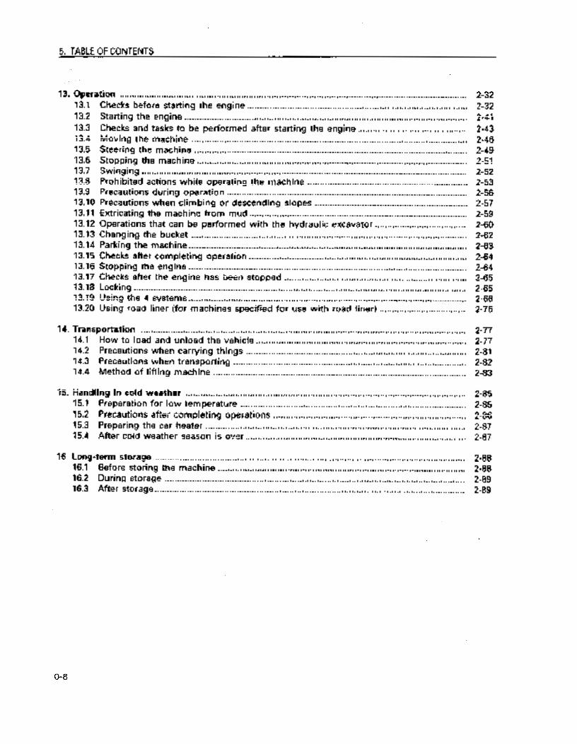
13. Operation . . . . . . . . . . . . . . . . . . . . . . . . . . . . . . . . . . . . . . . . . . . . . . . . . . . . . . . . . . . . . . . . . . . . . . . . . . . . . . . . . . . . . . . . . . . . . . . . . . . . . . . . . . . . . . . . . . . . . . . . .................... 2-32 13.1 13.2 13.3 13.4 13.5 13.6 13.7 13.8 13.9 13.10 13.11 13.12 13.13 13.14 13.15 13.16 13.17 13.18 13.19 13.20
Checks before starting the engine ......................................................................................... Starting the engine .................................................................................................................. Checks and tasks to be performed after starting the engine.. .......................................... Moving the machine ............................................................................................................... Steering the machine .............................................................................................................. Stopping the machine ............................................................................................................. Swinging ................................................................................................................................... Prohibited actions while operating the machine ................................................................. Precautions during operation ................................................................................................. Precautions when climbing or descending slopes .............................................................. Extricating the machine from mud ........................................................................................ Operations that can be performed with the hydraulic excavator.. ................................... Changing the bucket ............................................................................................................... Parking the machine ................................................................................................................ Checks after completing operation ........................................................................................ Stopping the engine ................................................................................................................ Checks after the engine has been stopped .......................................................................... Locking ...................................................................................................................................... Using the 4 systems.. .............................................................................................................. Using road liner (for machines specified for use with road liner) ...................................
2-32 2-41 2-43 2-46 2-49 2-51 2-52 2-53 2-56 2-57 2-59 2-60 2-62 2-63 2-64 2-64 2-65 2-65 2-66 2-76
14. Transportation ................................................................................................................................... 2-77 14.1 How to load and unload the vehicle ..................................................................................... 2-77 14.2 Precautions when carrying things ......................................................................................... 2-81 14.3 Precautions when transporting ............................................................................................... 2-82 14.4 Method of lifting machine ...................................................................................................... 2-83
15. Handling in cold weather ................................................................................................................. 2-85 15.1 Preparation for low temperature ......... . ................................................................................. 2-85 15.2 Precautions after completing operations .............................................................................. 2-86 15.3 Preparing the car heater ......................................................................................................... 2-87 15.4 After cold weather season is over.. ....................................................................................... 2-87
16. Long-term storage ............................................................................................................................. 2-88 16.1 Before storing the machine .................................................................................................... 2-88 16.2 During storage ......................................................................................................................... 2-89 16.3 After storage.. ........................................................................................................................... 2-89
O-8
https://tractormanualz.com

6. TABLE OF CONTENTS
17. Troubleshooting .................................................................................................................................. 17.1 Phenomena that are not breakdowns ................................................................................... 17.2 How to tow with the machine or be towed ......................................................................... 17.3 How to use the hook for towing light objects ..................................................................... 17.4 Precautions for special job sites ............................................................................................ 17.5 When the battery is dead ....................................................................................................... 17.6 When this phenomenon occurs .............................................................................................
Checks and Maintenance 18. Precautions in performing checks and maintenance . . . . . . . . . . . . . . . . . . . . . . . . . . . . . . . . . . . . . . . . . . . . . . . . . . . . . . . . . . . . . . . . . . . . .
19. Basic maintenance.. ............................................................................................................................ 3- 5 19.1 Essential information on oil, fuel and coolant.. ................................................................... 3- 5 19.2 Summary of electrical system.. .............................................................................................. 3- 9 19.3 Summary of hydraulic system ............................................................................................... 3- 9
20. Consumable Supplies .._.___...__..... _ _._...........___.._...............................,.................................................. 3-10
21. Use of fuel coolant and lubricants according to ambient temperature .................................... 21.1 Fuel/oil ....................................................................................................................................... 21.2 Coolant ......................................................................................................................................
22. Standard tightening torques for bolts and nuts.. .......................................................................... 22.1 List of tools necessary ............................................................................................................ 22.2 Torque table .............................................................................................................................
23. About regular replacement of important components . .._.. _ . . . . . . . . . . . . . . . . .._._..................................... 3-17
24. List of maintenance ........................................................................................................................... 24.1 Maintenance schedule.. ........................................................................................................... 24.2 Service time when using the hydraulic breakers ................................................................
25. Service procedures . . . . . . . . . . . . . . . . . . . . . . . . . .._................. _ . . . . . _ . . . . . . . . . .._....__....................................................... 3-23
26.
25.1 Initial setvcice after 250 hours of operation.. ....................................................................... 25.2 Maintenance that is not regularly scheduied ....................................................................... 25.3 Checks before starting operations ......................................................................................... 25.4 Service to be performed after every 50 hours of operation ............................................. 25.5 Service to be performed after every 100 hours of operation ........................................... 25.6 Service to be performed after every 250 hours of operation ........................................... 25.7 Service to be performed after every 500 hours of operation ........................................... 25.8 Service to be performed after every 1000 hours of operation ......................................... 25.9 Service to be performed after every 2000 hours of operation ......................................... 25.10 Service to be performed after every 4000 hours of operation .........................................
Inspections required ........................................................................................................................... 3-72 26.1 Before beginning work (Checks prior to starting operations) ........................................... 3-72 26.2 Checks before beginning work (Checks prior to starting operations) .............................. 3-72
2-90 2-90
2-92 2-92 2-92 2-93 2-97
3- 2
3-11 3-11 3-11
3-15 3-15 3-16
3-18 3-18 3-22
3-23 3-24 3-41 3-45 3-46 3-49 3-55 3-61 3-64 3-71
o-9
https://tractormanualz.com

6. TABLE OF CONTENTS
Specifications
27. Specifications ...................................................................................................................................... 4- 2
Optional Parts, Attachments
28 General precautions ........................................................................................................................... 5- 2
28.1 Safety precautions ................................................................................................................... 5- 2
28.2 Precautions when attachments are installed ........................................................................ 5- 3
29. Using seat belts.. ................................................................................................................................ 29.1 Seat belts ...................................................................................................................................
30. Information on optional attachments ..............................................................................................
30.1 Information on optional attachments ....................................................................................
30.2 Attachment combination table ............................................................................................... 30.3 Selecting tracks ........................................................................................................................ 30.4 Using the automatic leveling device .....................................................................................
5- 4 5- 4
5- 6 5- 6 5- 7 5- 8 5- 9
o-1 0
https://tractormanualz.com
Safety
A Warning!
Read and observe all safety precautions. Failure to do so may iead to accidents resulting in serious injury or loss of life.
Precautions for optional parts and attachments are included in this section on safety.
l-1
https://tractormanualz.com

7. BASIC PRECAUTIONS A Warninu! Follow these precautions to ensure safetv.
Strictly observe safety rules in the work place
* Only trained and qualified personnel can operate and maintain this equipment. l Follow all safety rules, precautions and procedures when operating or performing
maintenance on this machine. 0 Do not operate the machine if you are not feeling well, or if you are taking medicine
which will make you sieepy, or if you have been drinking. Operating in such a condition will adversely,affect your judgement and may lead to an accident.
* When workhg with another’operator.& wit&a person on worksite traffic duty, be sure i that all personnef understand all hand signals that are to be used.
Always install safety devices
0 Be sure all guards and covers are in the proper position. If damaged, have them repaired immediately.
0 Thoroughly understand the operation of all safety devices such as locking Ievers and Seat belts and use them property.
m Never remove safety devices. Always maintain them so that they function properly. Safety lock lever -, See item 13.14 “Parking the machine.” Seat belts - See item 30 “How to use the seat belts”
o Improper use of safety devices could lead to accidents and result in serious injury.
Do not wear loose fitting clothing; items of adornment or other items which can be caught or control levers or in moving parts ‘of the equipment_ Do not wear work clothes that are so&c with oil as they are flammable and are easily ignited. Always wear a helmet, safety glasses, safety shoes, masks and gloves as required by thC operation. Always wear protective items like safety goggles, a hdmet and gloves PartiCularI) when performing such tasks as pounding in pins with a hammer and cleaning elements witi compressed air which are likely to scatter metal fragments or foreign matter. Also make SurE that there is no one nearby.
Check that all protective equipment functions properly before using. Pounding in pins +
See item 13.13 “Changing the bucket” C2 r Cleaning elm 2
68
See item 25.2 “Unscheduled maintenance” @ Ti9
% Q
m
l-2
https://tractormanualz.com

a Warning! Failure to follow these safety precautions mav lead to an accident 7, BASlC PRECAUTIONS
Do not modify
l Modifications not recommended by Komatsu may lead to safety problems l Consult Komatsu or your Komatsu dealer before making any modifications. Komatsu will not
be responsiMe for any breakdowns or incidents resulting in injury caused by unauthorized modiications.
l Make sure that the safety lock lever is in the locked position when standing up from the operator’s seat If you accidentally touch the lever for moving the machine or rotating the arm and boom apparatus and it is not locked, there may be a sudden movement which may result in serious injury.
l When leaving the machine, make sure that the arm and boom apparatus has been lowered to the ground, place the safety lock in the locked position and secure all locks after stopping the engine. Always take the key with you. Position of the arm and boom apparatus -See item 13.14 “Parking the machinc.~
J
Do not jump on or off the machine. Above all, never mount or dismount the machine when it is moving. When mounting or dismounting, face the machine and use the handrails, steps on the track frame and the tracks. Do not grasp the operating control fevers when .mounting or dismounting. Always grasp the handrail and use the steps and tracks, maintaining contact in at least three places to make sure the body is securely supported while mounting or dismounting. Always maintain the handrails, steps and track shoes in a clean condition and remove any oil or mud that may be soiling them. Repair any damage and tighten any bolts that may have become loose. If you grasp the inside of the door when mounting and dismounting or moving on the track, the door will move and you may fall if it is not completely open and locked in that position. Make sure that the door is locked securely in w open position. Use the parts marked by arrpw A in the diagram below when getting on or off the &chine. ,Use the parts marked by arrow B when checking or carrying out maintenance, or when filling ti.e tank with oil.
AU301760 Al167320
1-3
https://tractormanualz.com

7. BASIC PRECAUTIONS A Warning! Follow these
orecautions to ensure safety
Keep flames away from fuel and oil
Flames may ignite fuel, oil and anti-freeze if they are in close proximity. Fuel is PatiCularb flammable and hazardous. l Do not smoke or light matches near flammable materials. 0 Refuel after stopping the engine and extinguishing cigarettes. 0 Tighten all fuel and oil caps securely. e Store fuel and oil in well-ventilated areas. 0 Fuel and oil should be kept in designated places and unauthorized persons should not be
allowed entry.
Precautions when handling at high temperatures
l Immediately after operation, engine coolant, engine oiI and transmission oil are hot and build up pressure. Serious bums may be caused if caps are removed, oil or coolant is drained or filters are changed in this condition. Wait until the temperature has gone done and perform these operations following the prescribed procedures.
0 To prevent hot coolant from boiling over 1) Stop the engine 2) Wait until the temperature of the coolant has gone down. 3) Remove the cap after slowly rotating it and releasing the pressure.
l To prevent hot oil from escaping. 1) Stop the engine 21 Wait until the temperature of the oil has gone down. 31 Remove the cap after slowly rotating it and releasing the pressure.
1-4
https://tractormanualz.com

4 Warning! Failure to follow these safety precautions mav lead to an accident 7. BASIC PRECAUTIONS
1
Inhaling air that includes asbestos dust may lead to lung cancer. This machine does not use asbestos but you should follow the precautions noted below if you are handling material that might have asbestos in it. l Do not use compressed air for cleaning. l Use water for cleaning so that asbestos dust will not be scattered in the air. l When operating the machine in a situation when there may be asbestos dust in the air always
be upwind. l Wear a designated respirator when necessary.
Do not get between moving parts such as between the arm and boom apparatus and the machine or between the arm and boom apparatus and the cylinders or put your hands, arms or other extremities there. When the arm and boom apparatus is moved clearance will change and this may lead to an accident invoiving serious injury.
Have a fire extinguisher and first aid kit on hand
Be prepared for fires by having fire extinguishers on hand. Read the label on them so YOU
will know how to use them. Have a first aid kit on hand and decide where to store it. Decide what should be done in the event of an accident or a fire. Decide who to contact in case of an emergency and copy down the telephone numbers in advance.
https://tractormanualz.com

7. BASIC PRECAUTIONS a Warning! Follow these
arecautions to ensure safetv
0 If you are going to use the machine with optional attachments installed please read the operating manual for the attachments and the section concerrkg attachments in this manual.
l Do not use attachments that have not been authorized by Komatsu or by Komatsu distributors. Use of unauthorized attachments may not only create safety problems but may alSo adversely affect the proper operation of the machine end the useful liie of the machine.
a Komatsu will not be responsible for any injuries, accidents or equipment breakdowns that are L caused by the use of unapproved attachments.
.
If it should become impossible to open the door, break the window glass with the attached hammer, then escape.
When escaping, remove the broken pieces of the glass from the sash so that yoti will not cut yourself with them. Take care not to slip on the broken and scattered pieces. Pati No. of hammer: 2OU-54-25910
Escaping method -+ See “12.7 HAMMER FOR EMERGENCY ESCAPE”.
Hammer ~~30160~
-j PRECAUTIONS WITH CAB GLASS 1
If by mistake the.cab glass on the work equipment side should crack, there is danger of direct contact between the operator’s body and the work equipment. This is extremely dangerous. If the glass is cracked, stop operations immediately and replace the glass.
l-6
https://tractormanualz.com

a FAILURE TO FOLLOW THESE SAFETY PRECAUTIONS
8. PRECAUTIONS FOR OPERATING! MAY LEAD TO AN ACCIDENT
8.1 BEFORE STARTING THE ENGINE
---I Ensure safety of the work site I I
Make sure that there are no hazardous conditions before beginning work. Decide on the optimal method for performing the operation after studying the terrain and the soil conditions of the work site. Levei inclines as much as possible and then proceed with operations. When working on roads or highways, ensure the safety of passing vehicles and pedestrians by cordoning off the area to be worked on and utilizing personnel to direct traffic. When you will be performing operations where there are likely to be under ground water, gas or high voltage electrical power lines, contact the appropriate utility companies, ascertain the locations and conduct operations so that these underground lines are not damaged. If you will be operating in water or will be crossing a stream or shallow body of water ascertain the condition of the ground subsidence, the depth of the water and the speed of the current and do not exceed the permissible water depth. Permissible water depth -. See item 13.9 Precautions in operating
0 Flammable material like wood chips, leaves, and paper trash should be kept from accumulating on or near the engine as they can cause a fire.
l Check for leaks in the fuel, lubrication and hydraulic systems and have them repaired. Wipe up oily residues. Where to check -, See item 13.1 .l Visual checks
0 Make sure of the location of fire extinguishers and how to use them.
Check the operator’s cab
l Do not leave parts and tools lying around in the cab. This will damage control levers and switches and may cause accidents.
0 Wipe up mud, oil and snow from the floor, levers, handrails and steps as they will become slippery if these things are allowed to adhere to them.
l Put on the seat belts after checking them and the associated hardware for damage or wear. Seat belts -. See item 30. Using seat belts
1-7
https://tractormanualz.com

8. PRECAUTIONS FOR OPERATING A Warnina! Follow these mecautions to ensure Safetv
Have sufficient ventilation in enclosed areas I
Exhaust gas from the engine is dangerous. l When running the engine in enclosed areas, open window and entrances. and improve
ventilation,
Adjust and clean mirrors and wi
0 Remove dirt from the surface of window glass and lights so that you can see ProPerhf l Clean the surface and adjust the rear under view mirror (oPtional so that the lower Potion of
the rear of the vehicle may be best seen from the cab. If the glass is broken, rephe it. 0 Make sure that the head lights and operating lights are installed so that the work Planned
may b6 Performed. Check to make sure they light up properly.
Before starting the engine, adjust the operator’s seat so that you can Operate in a easy POsitiOn. If the operator’s seat is not adjusted correctly, you may make a mistake in operation or be fatigued, and that can cause accidents_ Adjust the operatof s seat so that you can operate the control levers and pedals fully with Your beck fmed to the seat back.
Adjustment of operator’s seat -+ See “13.1.3 ADJUSTMENT OF’OPERATOR’S SEAT”. Before starting the engine, confirm that the safety lock lever is at the LOCK position. Befare starting the engine, be sure to perform a ‘Waik-around check-, “Check before starting” and “Operation and check be- fore starting engine”
Walk-around check -+ See “73.1.1 WALK-AROUND CHECK”. Check before starting ‘--,
See ‘13.11 CHECK- BEFDRE STARTING”. Operation and check before starting engine + See “13-1.4 OPERATION AND CHECK BEFORE STARTING”.
Confirm by the above checks that the machine is free from trouble. If trouble is found and it cannot be repaired, be sure to but a warning tag on the work equipment lever.
1-8
-. https://tractormanualz.com
&Warning! Failure to follow these safety precautions mav lead to an accident 8. PRECAUTlONS FOR OPERATING
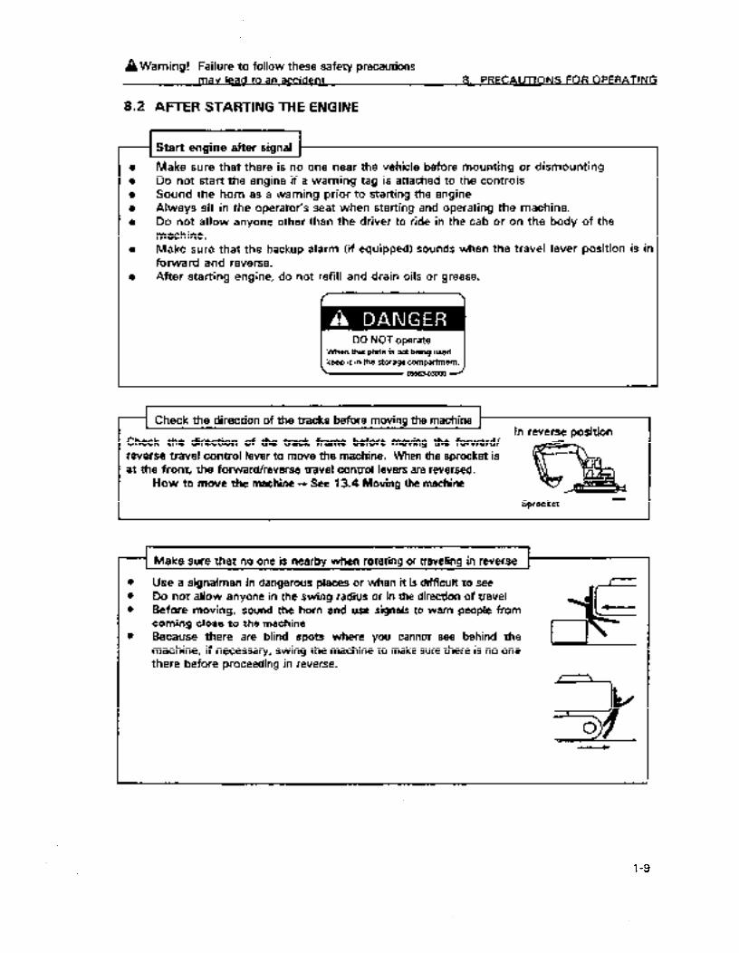
8.2 AFTER STARTING THE ENGINE
rl Start engine after signal
Make sure that there is no one near the vehicle before mounting or dismounting IJo not start the engine if a warning tag is attached to the controls Sound the horn as a warning prior to starting the engine Always sit in the operator’s seat when starting and operating the machine. Do not allow anyone other than the driver to ride in the cab or on the body of the machine. Make sure that the backup alarm (if equipped) sounds when the travel lever position is in forward and reverse. After starting engine, do not refill and drain oils or grease.
( When this plate is not being used
DO NOTo.IR(BJ
keep it in the storage compartment.
Check the direction of the tracks before moving the machine
Check the direction of the track frame before moving the forward/ In reverse position
reverse travel control lever to move the machine. When the sprocket is at the front, the forward/reverse travel control levers are reversed.
How to move the machine -, See 13.4 Moving the machine
Sprocket -
Make sure that no one is nearby when rotating or traveling in reverse
0 Use a signalman in dangerous places or when it is diicult to see 0 Do not allow anyone in the swing radius or in the direction of travel 0 Before moving, sound the horn and use signals to warn people from
coming close to the machine
I 0 Because there are blind spots where you cannot see behind the I __J’ machine, if necessary, swing the machine to make sure there is no one
I there before proceeding in reverse.
I
1-9
https://tractormanualz.com
8. PRECAUTIONS FOR OPERATING A Wamino! Follow these precautions to ensure safety
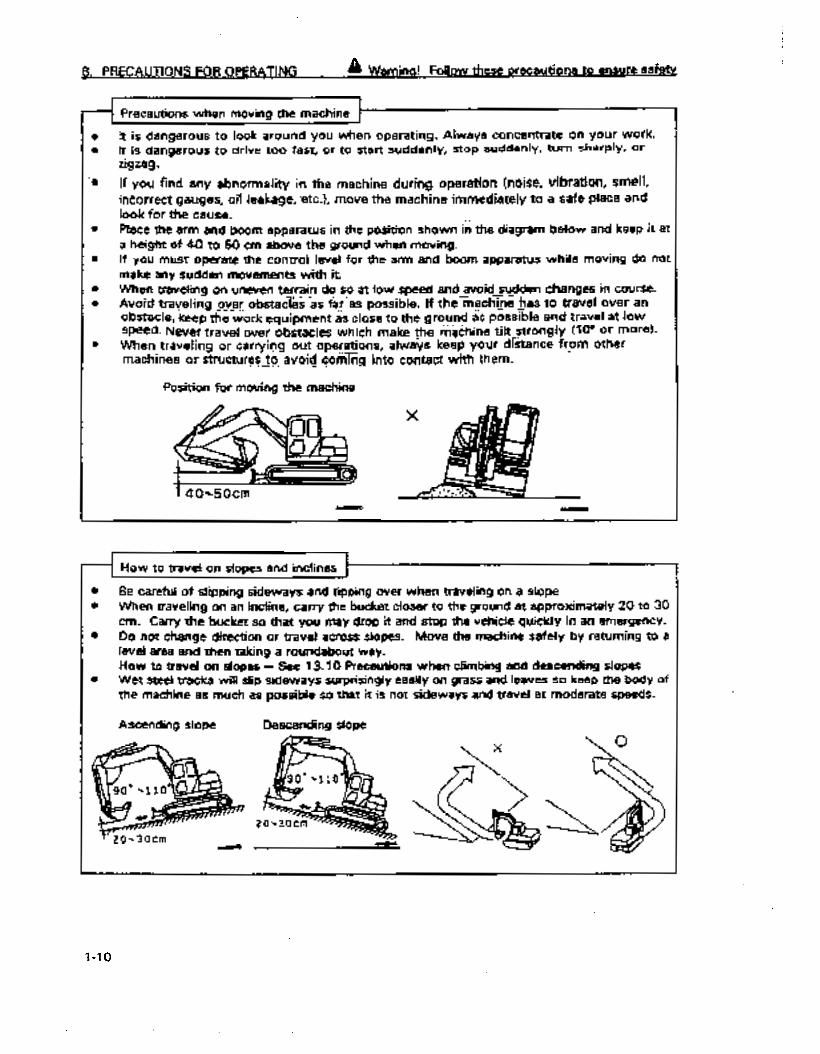
-I Precautions when movina the machine ~---___ I
It is dangerous to look around you when operating. Always concentrate on your work. It is dangerous to drive too fast, or to start suddenly, stop suddenly, turn sharply, Or zigzag..
If you find any abnormality in the machine during operation {noise, vibration, smek ineorrect;gauges, oil leakage, -etc.), move the machine immediately to a safe place and look for the cause. Place the arm and boom apparatus in the po&on shdwn in the diagram below and keep it at a height of 40 to 50 cm above the ground when moving. If you must operate the control level for the arm and boom apparatus while moving do not make any sudden movements with it. When traveling on uneven terrain do so at low speed and avoid sudden &anges in course. .- -- _ _. - Avoid traveling over obstacles as f&-as possible. If the rnach%&‘@ to travel over an ._.--. _ _ obstacle, keep the work Equipment as close to the ground as possrble and travel at low speed. Never travel over obstacles which make tie t&chine tilt_strongiY (IO0 or more)- . . _ _ __ When traveling or carryiqg out operations, always keep your distance from other
.-- machines or structures to avpid_ Goti%g into contact with them. _ _-.._ -....
Position for moving the machine
l Be careful of slipping sideways and tipping over when traveling on a slope l When traveling on an incline, carry the bucket closer to the ground at approximately 20 to 30
cm. Carry the bucket so that you may drop it and stop the vehicle quickly in an emergency. 0 Do not change direction or travel across slopes. Move the machine safely by returning to a
level area and then taking a roundabout way. How to travei on slopes - See 13.10 Precautions when. climbing and descending slopes
l Wet steel tracks will slip sideways surprisingly easily on grass and leaves so keep the body of the machine as much as possibie so that it is not sideways and travel at moderate speeds.
Ascending slope Descending slope
I-10
https://tractormanualz.com

A Warning! Failure to follow these safety precautions mav lead to an accident 8. PRECAilTlONS FOR OPERATING
Do noi excavate under an overhang as it is dangerous and dirt and the machine. Do not excavate directly up to base of the machine. The ground machine might fall.
sand will come down on
will be unstable and the
l Coming ciose to high voltage power lines may result in electric shock. Maintain the safe distances from power lines noted below.
l The foilowing are effective in preventing accidents 1) .Wear shoes with leather or rubber soles. 2) Use a signalman to warn you when you have come to dose to a power line.
a If the arm and boom apparatus should, in some eventuality, come in contact with power lines, the operator should not leave the cab.
0 Do not let anyone come dose to the machine when operating near high voltage power lines. a Check with the power company about the voltage of ttte lines at the work site.
Voltage of power lines Minimum safe distance
6.6kV 3m
33.0kV 4m
66.OkV 5m
154.0kV am I 275.0kV I 10 m -P
During operation%, if you extend your hands or feet from the operator’s cab to any movable parts, there is danger of getting your hands or feet caught and suffering serious injury. Never extend your hands or feet.
l-11
https://tractormanualz.com

8. PRECAUTIONS FOR OPERATING A Warnina! Follow these orecautions to ensure safetv
0 Be sufficiently careful to avoid hitting the boom or arm on anything when operating in places with restricted space like tunnels, on bridges or under power lines.
Ensure good visibility
l When operating in dark piaces turn on the operating light and head lights and if necessary provide additional fighting.
l When visibility is poor due to fog, snow or rain postpone operations and wait until visibility improves so that there is nothing obstructing the operation.
l The machine will slip sideways very easily on snow or icy road surfaces so travel at low speeds and avoid sudden starts, stops and sudden swings of the boom.
0 Proceed carefully when clearing snow because there are objects buried in the snow which cannot be seen.
0 As much as possibie, avoid coming near cliis, road shoulders and deep ditches as the ground near them is unstable. If the ground collapses from the weight and vibration of the machine it might tip over or fall. Be particular careful because the ground is unstable after rain or blasting.
0 Areas where there is din piled on the ground and areas near ditches which have been excavated are unstable and may collapse from the weight and vibration of the machine so that it tips.
l When working in areas where there is likely to be falling rock and dirt, wear a head guard.
1-12
https://tractormanualz.com
AWarning! Failure to follow these safety precautions mav lead to an accident 8. PRECAUTIONS FOR OPERATING
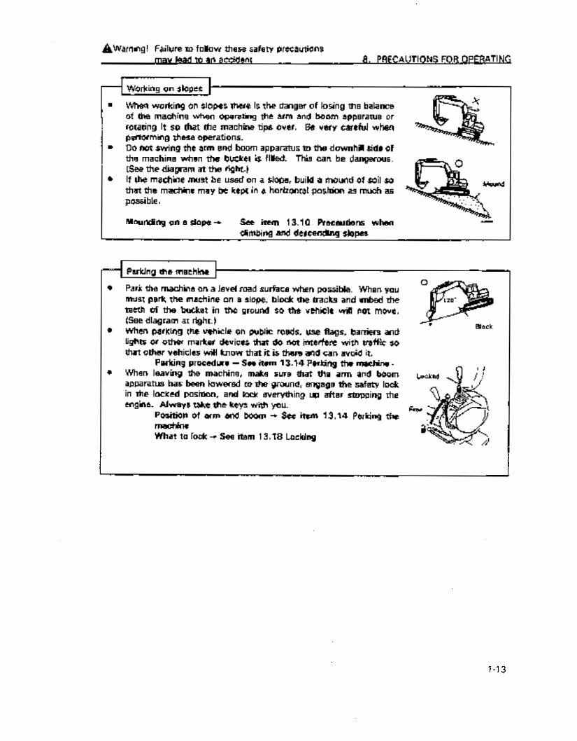
When working on slopes there is the danger of losing the balance of the machine when operating the arm and boom apparatus or rotating it so that the machine tips over. Be very careful when performing these operations. Do not swing the arm and boom apparatus to the downhill side of the machine when the bucket is filled. This can be dangerous. (See the diagram at the right.) If the machine must be used on a slope, build a mound of soil so that the machine may be kept in a horizontal position as much as possible.
Mounding on a slope + See item 13.10 Precautions when climbing and descending slopes
Parking the machine
Park the machine on a level road surface when possible. When you must park the machine on a slope, block the tracks and imbed the teeth of the bucket in the ground so the vehicle will not move. (See diagram at right.) When parking the vehicle on public roads, use flags, barriers and lights or other marker devices that do not interfere with traffic so that other vehicles will know that it is there and can avoid it.
Parking procedure -c See item 13.14 Parking the machine - When leaving the machine, make sure that the arm and boom apparatus has been lowered to the ground, engage the safety lock in the locked position, and lock everything up after stopping the engine. Always take the keys with you.
Position of arm and boom -c See item 13.14 Parking the machine What to lock -c See item 13.18 Locking
1-13
https://tractormanualz.com

8. PRECAUTIONS FOR OPERATING A Wamina! Follow these precautions to ensure safetv
8.3 TRANSPORT THE VEHICLE
Precautions when loading and unloading the vehicle
Loading and unloading the machine for transport is especially hazardous. Be especially cautious. When loading and unloading, the engine should be idling slowly and should be run in low gear. Select a firm, ieve place for loading and make sure that it is a sufficient distance from the shoulder of the road. Use ramps that are of adequate strength and make sure that they are sufficiently wide, long and thick for safe loading and unloading. If the ramps are likely to bend significantly, reinforce them with blocks. Remove oil residues and foreign matter that may be stuck to the ramps so that the machine will not slide. Remove mud from around the tracks. Never correct the position of the tracks on the ramp while on the ramp. If you need to correct the position of the tracks, back off of the ramp, correct the position of the tracks and the remount the ramp. If you are going to swing the arm and boom apparatus on the trailer, do so with caution as the machine’s footing is unstable. After the machine has been loaded, secure the vehicle with wedges and wire rope. How to load and unload - See item 14. Transporting How to secure + See item 14. Transporting
Distance between ramps
Less than 15 degrees
1 Precautions when transporting 1
l Transport the vehicle safely in accordance with all pertinent regulations. l Consider the maximum width, height and weight of the machine when it is loaded on the
trailer when deciding on a route to transport the vehicle.
1
1-14
https://tractormanualz.com
AWarning! Failure to follow these safety precautions mav lead to an accident 8. PRECAUTIONS FOR OPERATING
8.4 BATTERY
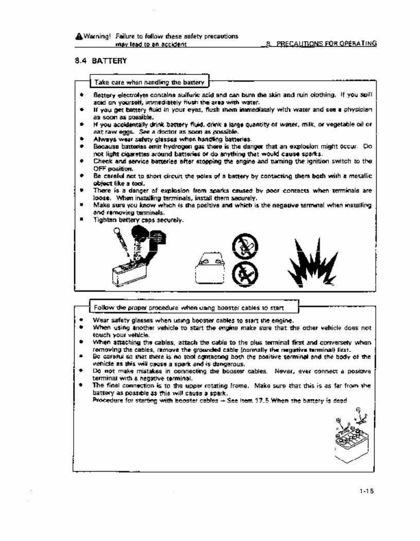
Battery electrolyte contains sulfuric acid and can burn the skin and ruin clothing. If you spill acid on yourself, immediately flush the area with water. If you get battery fluid in your eyes, flush them immediately with water and see a physician as soon as possible. If you accidentally drink battery fluid, drink a large quantity of water, milk, or vegetable oil or eat raw eggs. See a doctor as soon as possible. Always wear safety glasses when handling batteries. Because batteries emit hydrogen gas there is the danger that an explosion might occur. Do not light cigarettes around batteries or do anything that would cause sparks. Check and service batteries after stopping the engine and turning the ignition switch to the OFF position. Be careful not to short circuit the poles of a battery by contacting them both with a metallic object like a tool. There is a danger of explosion from sparks caused by poor contacts when terminals are loose. When installing terminals, install them securely. Make sure you know which is the positive and which is the negative terminal when installing and removing terminals. Tighten battery caps securely.
I I __f Follow the orooer orocedure when usina booster cables to start 7
1 . . . I
Wear safety glasses when using booster cables to start the engine. When using another vehicle to start the engine make sure that the other vehicle does not touch your vehicle. When attaching the cables, attach the cable to the plus terminal first and conversely when removing the cables, remove the grounded cable (normally the negative terminal) first. Be careful so that there is no tool cgntacting both the positive terminal and the body of the vehicle as this will cause a spark and is dangerous. Do not make mistakes in connecting the booster cables. Never, ever connect a positive terminal with a negative terminal. The final connection is to the upper rotating frame. Make sure that this is as far from the battery as possible as this will cause a spark. Procedure for starting with booster cables -, See item 17.5 When the battery is dead
? 9 nx 2
1-15
https://tractormanualz.com

8. PRECAUTIONS FOR OPERATING A Wamino! Follow these orecautions to ensure safety
8.5 TOWING
Attach wire to frame when towing
l
e 0
0
0
0
l
Improper towing can result in injury Use a wire rope of sufficient strength retative to the weight of your machine or if YOU use another vehicle to tow your machine. Never tow on a slope. Do not use a wire rope with kinks or twists in it or one which is damaged. Do not straddle the cable or wire rope used in towing. Do not allow anyone in between the towing vehicle and the machine to be towed when they are being connected or are connected. Keep the towing connection on the machine and the connected part of the towing vehicle in a straight line. Place wooden bumpers between the wire rope and the body to prevent damage to either the wire rope or the body. Do not use the hook for towing light weight objects to tow the vehicle. How to tow the machine - See item 17.2 How to tow the vehicle
1-16
https://tractormanualz.com

A Warning! Failure to follow these safety, precautions mav lead to an accident
8.6 PRECAUTIONS FOR HOISTING OPEtiTlONS
8. PRECAUTIONS FOR OPERATING
0 Pedom hoisting operations slowly with the engine running at low RPM 0 Avoid sudden movements of the control levers and sudden acceleration. l Rotation speed is 3 or 4 times that of mobile cranes. Exercise special caution when rotating.
0 Do not leave the operator’s seat when a load has been lil%d and is suspended in the air.
Do not perform unreasonable operations
0 Operations that exceed the’capabiiies of the machine may cause accidents or breakdowns. 0 Perform hoisting operations within the specified load limits 0 Do not perform operations which might damage the equipment such as hoisting loads
exceeding the specified load limits or shock load. 0 Do not move a load laterally or longitudinally or pull the arm in as these movements are
dangerous.
1 Do not move the machine while hoisting loads 1
0 Do not move the machine while performing hoisting operations.
Be careful of position for hoisting operations
0 There is the danger that the wire rope or hoisting ring may come off the hook if the bucket is not in the proper position. Be careful and make sure the bucket is in the proper position so that the hook is at the proper angle and wire rope and rings will not come off.
I-17
https://tractormanualz.com
A FOLLOW THESE PRECAUTIONS Sm PRECAUTIONS FOR MAINTENANCE TO ENSURE SAFl3-Y
9.1’ PRIOR TO PERFORMING MAJNTENANCE
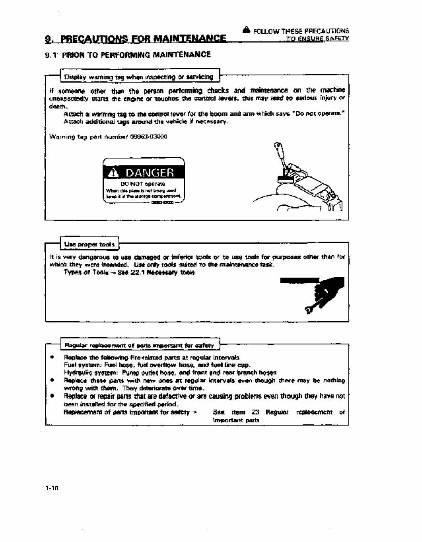
Display warning tag when inspecting of servicing
If someone other than the person performing checks and maintenance on the machine unexpectedly stans the engine or touches the control ievers, this may lead to serious injury or death.
Attach a warning tag to the control lever for the boom and arm which says “Da not operate.” Attach additional tags around the vehicle if necessary.
Warning tag part number 09963-03000
it is very dangerous to use damaged or inferior tools or to use tools for purposes other than for which they were intended. Use only toots suited to the maintenance task
Types of Tools - See 22.1 Necessary tools
7 0
Regular replacement of parts important for safetv
0 Replace the following fire-related parts at regular intervals Fuel system: Fuel hose, fuel overflow hose, and fuel line cap. Hydraulic system: Pump outlet hose, and front and rear branch hoses
0 Replace these parts with new ones at regular intervais even though there may be nothing wrong with them. They deteriorate over time.
0 Replace or repair parts that are defective or are causing problems even though they have not heen installed for the specified period. Replacement of parts important for safety + See item 23 Regular replacement of
i important parts
1-18
https://tractormanualz.com
A Wamina! Follow these orecautions to ensure safetv 9. PRECAUTIONS FOR MAINTENANCE
STOP ENGINE BEFORE CARRYING OUT INSPECTlON ,AND MAINTENANCE i When carrying out inspection and maintenance, park the machine on level ground where there is no danger ot failing rocks or land slides, or of flooding if the land is low, then lower the work equipment to the ground and stop the engine.
Operate the right work equipment control lever several times to the RAlSE’and‘LOWER positions to release the remaining pressure in the hydraulic circuit, then set the safety lock lever to the LOCK position. _.
Always use WD people for maintenance operations that require the engine to be as flushing the radiator and secure the safety lock lever in the locked position. be in the operator’s seat so that he can stop the engine at any time. He should careful not to touch any levers other than those necessary for the operation. Persons performing service should be careful so that they do not or their clothing does not touch any moving parts.
Free
running such One should
be extremely
r-i RULES TO FOLLOW WHEN ADDING FUEL OR OIL 1
IL 1
If any flame is brought close to fuel or oil, there is danger that it will catch fire, so always follow the precautions below. _ 0 Stop the engine when adding fuel or oil. l Do not smoke. l Spilled fuel and oil may cause you to slip, so always wipe it up immediately. l Always tighten the cap of the fuel and oil fillers securely. l Always add fuel and oil in a well-ventilated place.
I Ams5020 AOOS5030 Aoo55040
1-19
https://tractormanualz.com

9. PRECAUTIONS FOR MAINTENANCE
a Warning! Failure to follow these safety precautions mav lead to an accident
Radiator coolant level
0 If you need to add coolant to the radiator, do so after stopping the engine and waiting for it to cool down.
0 Slowly loosen the cap before removing to allow pressure to escape.
Lighting for the service operations
Use explosion proof lighting for checking fuel, oil, coolant and battery fluid levels. If you fail to do so the material may be ignited and there will be the danger of explosion.
Never climb on to the engine hood. There is danger that you will slip and fall.
PREVENTION OF FIRE
Carrying out maintenance involves handling objects such as fuel and batteries which may cause a fire. To prevent fire, do as follows.
l Keep fuel and other flammable oil and fluids well away from fire.
l Always use a non-flammable oil for washing parts.
l Put out any fires that may cause the fuel or oil to ignite.
l Always have a fire extinguisher or other fire-fighting equipment available.
l Do not smoke when carrying out inspection and maintenance operations.
I-20
https://tractormanualz.com
A Warnina! Follow these mecautions to ensure safew 9. PRECAUTIONS FOR IvlAlNTENANCE
9.2 DURING MAINTENANCE I
- Do not allow other persons in the work area other . than those involved in the maintenance operation
Persons other than necessary, authorized personnel should not be allowed in the work area. Be careful of persons in the surrounding area. Extra caution should be exercised when performing grinding, and welding operations or when using a sledge hammer.
Attachments that have been removed
When removing attachments or reinstalling them make sure that they are piaced in a stable position so that they do not fall over.
Working under the machine
0 Before working under the machine, aiways lower the boom and arm to the ground or to the
I lowest position. l Always secure the tracks of the vehicle with blocks so they cannot move. l Neve; work under the machine if the machine is not proper& supported.
Oil that has spilled, excess grease and scattered metal fragments are dangerous. Always keep the machine clean. Allowing water to get into electrical system is dangerous and may cause improper and faulty operation. Do not use water or steam to clean sensors, connectors or the inside of the cab.
l-21
https://tractormanualz.com

A Warning! Failure to foltow these safety precautions 9.
Precautions with battery
Remove the connection to the negative terminal to stop the flow of electrical current if you are going to repair the electrical system or do elect& wetding.
Handling battery -, Se& ‘17.5 IF BATTERY IS DISCHARGED”.
1 Handling -high pressure hoses
0 Do not bend or clamp hard objects on high pressure hoses. Do not use piping, tubes or hoses with bends or cracks as they may rupture.
l Always repair fuel hoses and hydraulic hoses that have breaks or have soft spots.
0 Always remember that hydraulic lines for the boom ,and arm are under pressure. a Do not add fiuid. drain fluid, check or engage in repair operations until the pressure gauge
reads zero. * Leaks of hydraulic fluid under pressure from small holes can be dangerous if it gets on the
skin or in the eyes. Wear safety glasses and thick gloves, and use a piece of card board or a sheet of plywood to test the leak that you wish to check.
0 If your are hii by a jet of hydraulic fluid under pressure see a doctor immediately.
l-22
https://tractormanualz.com
A Wamino! Follow these orecautions to ensure safetv 9. PRECAUTlONS FOR MAINTENANCE
Be careful when performing maintenance when the engine is hot or there is high pressure i
Engine coolant, engine oil, transmission fluid, and hydraulic .fluid are hot and under pressure immediately after turning off the machine. Serious burns may be caused if caps are removed, oil or coolant is drained or filters are changed in thii condition. Wait until the temperature has gone done and perform these operations following the prescribed procedures.
Cleaning the cooling system + See item 25.2 Non-scheduled maintenance Che&ing the ieveis of the coolant
and hydraulic fluid tanks -c See item 25.3 Checks before starting operations Checking lubricating oil, adding oil -, See items 25.3-25.9 Regularly scheduled maintenance Changing oil and filters -, See items 25.3-25.9 Regularly scheduled maintenance
Se careful of high
Grease is pumped into the track tension adjustment system at high pressure. If the tracks are adjusted in a manner other than by the prescribed maintenance procedure the plugs and grease fittings may fly out and cause injury to personnel.
When loosening plugs for allowing grease to escape, do not loosen them more than one turn Do not put your face, hands, feet or other part of your body directly in front of any grease drain plug or valve.
Adjusting track tension - See item 25.2 Unscheduled maintenance
I 1 1 Rotating fans and belts
l Do not let anything that might easily get caught in the fan get close to where it is rotating. 0 Never, ever, touch the fan blade or the fan belts as tools and body parts may be cut off if
allowed to contact these things.
l-23
https://tractormanualz.com

9. PRECAUTIONS FOR MAINTENANCE
A Warning! Failure to follow these safety precautions mav lead to an accident
Waste materials
0 Do not discard waste oil in sewer systems or in a river. 0 Always put used oil drained from the machine in a container. Never allow oil to drain directly
on the ground 0 Follow applicable laws and regulations when disposing of hazardous materials such as oil,
fuel, coolant, solvents, filters and batteries.
1-24
https://tractormanualz.com

IO. WHERE SAFETY LABELS HAVE BEEN ATTACHED
Always keep these labels clean. If they are lost m-attach them or replace them with new ones.
As shown below, there other labels other than the safety labels and they should be handled in the same
way.
10.1 WHERE SAFETY LABELS Ai3E LOCATED
1-25
https://tractormanualz.com

10. WHERE SAFETY LABELS HAVE BEEN ATTACHED
1.
2.
Warnings for leaving operator’s seat
(203-00-61270)
a WARNING
To avoid hitting unlocked operation levers,
lower equipment to ground and move SAFETY LOCK LEVER (located near seat) to LOCK position before standing up from operator’s seat.
Sudden and unwanted machine movement
can cause serious injury or death.
Warnings before operating machine
(203-00-61291)
g, WARNING n -
To prevent SEVERE INJURY o.r DEATH.
do the following before moving machine
or its attachments:
. Honk horn to alert people nearby.
. Be sure no one is on or near machine
or in swing area.
. Rotate cab for full view of travel path
if it can be done safely.
. Use spotter if view is obstructed.
Follow above even if machine equipped
with travel alarm and mirros.
203-00-6129~ I
3.
4.
Cautions for handling interference prevension
device (21 W-98-21 420)
Warning when opening front window
(203-00-61280)
IA WARNING When raising w_indow, lock it in place with lock pins on both sides.
Failing window can cause injury.
c 203-00-61280 -
l-26
https://tractormanualz.com

10. WHERE SAFETY LABELS HAVE BEEN ATTACHED
5.
6.
Warnings when adjusting track tension (14X-98-11551)
A WARNING High pressure hazard at track adjuster.
When adjusting track tension, never open plug more than one turn. Turning further could cause injury from flying plug and grease.
See manual for adjustment instrucfions.
14x-9&11551 _
Warning for removing window (2OU-98-21910)
a WARNING To prevent SEVERE INJURY or DEATH,
follow instructions below: l To avoid contact
with boom. DO NOT lean outside right side window.
elf right side window is broken or becomes dislodged, have it repaired immediately.
20U -98-21910 -
7.
8.
Warnings for high voltage (203-00-61310)
g DANGER
Hazardous voltage hazard. Serious injury or death can occur if
machine or attachments are not kept
safe distance away from electric lines.
Line voltage Safe Distance 6.6kv At least 10h13m)
66.Okv At least 16ft(5m) 275.Okv At least 33WOm)
Warnings for operation, inspection and main- tenance ( 14X-98-1 1580)
A WARNiNG improper operation and maintenane can cause serious injury or death.
Read manual and labels before operation and maintenance. Follow instructions and warnings in manual and in labels on machine.
Keep manual in Machine cab near operator. Contact komatsu distributor for a replacement manual.
14X-98-11580 -
1-27
https://tractormanualz.com

10. WHERE SAFElY LABELS HAVE BEEN Al-i-ACHED
9. Warnings for high temperature coolant (14X-98-115313
LL WARNING Hot water hazard.
To prevent hot water from spurting out :
*Turn engine off. l Allow water to cool. 0 Slowly loosen cap to
relieve pressure before removing.
14X.98-11531 -
10. Warnings for opening engine hood (ZIW-98-214803
/ ACAUTION 1
12. Warnings for high temperature hydraulic oil (203-00-61260)
HYDRAULIC
OIL
g, WARNING
Hot oil hazard
To prevent hot oil from spurting OUC
a Turn engine off. . Allow oil to cool. l Slowly loosen cap to relieve pressure
before remqving.
13. Warning for position of cancel switch (2OU-98-21521)
11 Keeping out of turning area (2OY-00-21270)
14. Warning for handling battery. (14X-98-1 1370)
\ Keep off swing area / A WARNING
1-28
https://tractormanualz.com

OPERATION
2-1
https://tractormanualz.com

11. THE NAME OF EACH PART
11.1 GENERAL VIEW OF THE VEHICLE
Arrows indicate direction in this manual.
Right side Offset cylinder. Firy boom Rear
3ucket cvlinder 4
Buck<t C
2-2
https://tractormanualz.com

11. THE NAME OF EACH PART
11.2 GENERAL VIEW OF CONTROLS AND GAUGES
Travel lever Oecelefation switch Boon, otfset Oeual
Left arm and boom Horn Sw i tCh
aooaratus control lever arm and OoOm aDoar atus control lever
LOCL lever \ Pedal lock
Blade control lever
Lam
Heater
wiOer
swi tCh XP
swi tell :-
swi tCh 3 r h40ni tor oanei
1 Fuel control
Engine coolant
Service meter Preheat tcmpertture
gauue Fuel gauge kr switch
lqnition Switch
!jwing lock brate release swi ta
Charge Engine-oil Electrical Mode Oepth Mode selection switch indicator level monitor system indicator indicator
monitor
Overrtaemear swftcn \
Travel soeea dcceterator
-
2-3
https://tractormanualz.com
12. EXPLANATION OF EACH DEVICE
Each device necessary for operation is explained. The most important thing for proper, safe and smooth
operation is to properly understand the ways to operate these devices and to understand what the gauges mean.
12.1 VEHICLE MONITOR PANEL I
A- E C AD3091dO
The monitor panel shows the basic items that must be checked before starting the engine.
Lights will come on for anything that is abnormal on the monitor panel.
The light will go out when the engine is started even if there is something abnormal.
A. Emergency stop items (I 2.1.1)
When the engine is running and there is something abnormal the item that needs to be taken care of will be indicated.
The monitor light will flash and a buzzer will sound when something is abnormal.
A Caution!
Immediately cease operations and check and repair the problem when these monitors flash.
2-4
https://tractormanualz.com

12. EXPI ANATION OF EACH DEVICE
B. Gauges (121.2)
Indicates the amount engine.
C. 4 systems 112.1.3)
of coolant and fuel remaining in the
Indicates and sets the preventive devices for the bucket cab and canopy and the automatic control devices for the arm and boom apparatus.
D. indicator lamps (12.1.4)
Indicates preheat condition
E. Basic check items (12.1.5) (Optionail
Of the items that should be checked prior to starting the engine, displays the oil level.
If there is an abnormality the monitor for that item will light up.
When the engine is started the light will go out even though there is an abnormality.
Additional explanation
The engine oil level indicator is an optional item so that on those vehicles that do not have this optional item installed there will be no indication even when the level is low.
Check the oil level before starting the engine.
2-5
https://tractormanualz.com

12. EXPLANATION OF EACH DEVICE
12.1. I A Emergency stop items
4 Caution!
if the monitor is fiashing, stop the engine immediately and do the following.
1. Engine oil pressure
When the engine lubricating oil pressure goes below normal, this indicator will light up and a buzzer will sound. If it lights up, stop the engine and check in accordance with item 17.6., “When this phenomenon occurs”
Additional explanation
When the ignition switch is in the ON position when the engine is not running, the indicator will light up but there is nothing wrong.
2-6
https://tractormanualz.com

12. EXPLANATION OF EACH DEVICE
2. Battery charge
If the battery is not charging properly while the engine is running the indicator will light up and a buzzer will sound. If the indicator light comes on, stop the engine, check the tension. of the belt and if it is abnormal, refer to item 17.6 “When this phenomenon occurs.’
rl I -t
Additional explanation
When the ignition switch is in the ON position when the engine is not running, the indicator will light up but there is nothing wrong.
12.1.2 B Gauges
1. Engine coolant temperature gauge
This gauge indicates the temperature of engine coolant. If the temperature is normal while the engine is running the green light will come on. When it reaches the highest level the light will flash and a buzzer will sound. If the red light comes on or flashes, run the engine at a low idle and wart for the temperature to go down to the green range. After starting the engine, warm up the engine until the gauge is in the green range.
2. Fuel gauge
This gauge indicates the amount of fuel in the fuel tank. If the fuel level is normal while the engine is running, the light will come on in the green range. The light will flash only when it is in the red range. If the light flashes in the red range while the engine is running, this indicates that there is less than 33 P of fuel remaining and that you should check and refuel the tank.
After turning the ignition switch to the ON position, the gauge will not show the correct amount for a short period but this does not indicate that there is anything wrong.
2-7
https://tractormanualz.com
12. EXPLANATION OF EACH DEVICE
3.
run.
Service Meter
This gauge indicates the amount of time the vehicle has been
Set the interval for regular maintenance with the display. The service meter will advance even if the machine does not
move if the engine is running. When the engine is running the indicator (4 i above the meter
will come on and this indicates that the meter is running. Regardless of the speed the engine is running when the engine
is run for 1 hour the meter will advance 1 numeral.
12.1.3 C 4 systems
1. Electrical system
If there is anything abnormal in the 4 systems (Preventative systems and automatic control device for the boom and arm) the gauge will light up or flash and a buzzer will sound. Stop the engine. The cause of the abnormality will be indicated in the depth display section as an error code so check in accordance with section “17.6 When this happens.”
When the ignition switch is ON and the engine is being started or stopped, the light will come on for a second and the buzzer will sound but this does not indicate that there is anything abnormal.
2. Mode selection switch
This is a switch that enable you to select one of the following modes: Depth display 0 set mode, depth mode, height mode, offset mode.
3. Set switch
This is a switch that sets or clears the mode selected by the mode selection switch.
0’ ul
El ~o~o~o~olo~o~ h
Electrical u system
Offset mode
2-8
https://tractormanualz.com

12. EXPLANATION OF EACH DEVICE
4. Depth display mode
This indicates the depth of the bucket from the surface of the
ground. “UP” is always displayed when the bucket is above ground.
It also indicates the depth from a standard plane when a standard plane height has been set below the surface of the ground
(when in depth display 8 set mode). When there is something wrong in the 4 systems the numeral
in the second column will indicate the location of the problem.
5. Depth mode indicator
This gauge will be lit when how much the boom is to be lowered is set. This will come on when the mode selection switch
is set to “depth” and indicates that the amount that the boom is to be lowered is set.
6. Height mode indicator
This gauge is lit when the height the boom is to be raised is set. This indicator will come on when the mode selection switch
is set to “height’ and indicates that the height the boom is to be raised is set.
7. Offset mode indicator
This gauge is lit when the amount offset to the left is set.
000
l-2 II- Ii co -iI
lm \m
2-9
https://tractormanualz.com

12. EXPLANATION OF EACH DEVICE
Do not operate the machine when the override/clear switch is ON
Because the 4 systems do not work and the arm and boom apparatus will not stop automatically there is danger that it will hi
iise this switch to move the boom and arm apparatus when there is a problem with the 4 systems and the boom and arm apparatus has stopped.
(I 1 ON: Clear/ Override automatic stop (2) OFF: Normal operation
When the switch is in the ON position, removing your hand from it will automatically return it to the OFF position.
12.1.4 D Display. lights
1. Preheat monitor
This will indicate the preheating time required when endeavoring to start the engine when ambient temperature is below ooc.
This fight will come on when the preheat switch is placed in the HEAT position and after approximately 18 seconds will go out indicating that preheating has been completed.
12.1.5 E Basic check items (optional)
1. Engine oil amount
This light will come on when there is insufficient oil in the engine oil pan. Check the amount of oil in the engine oil pan and add when necessary.
Additional explanation
The vehicle has an oil volume display but if there is a problem
in those vehicles without this optional part, the monitor light will
not come on because this is an option.
2-10
https://tractormanualz.com

12. EXPLANATION OF EACH DEVICE
12.2 SWITCHES
AE30916A
1. Ignition switch
Used to start and stop the engine.
OFF position
The ignition key may be inserted or removed in this position, the eiectrical systems switch is turned off and the engine is off or will stop running when placed in this position.
ON position
Current will flow to the charging system and light system. Keep the switch in this position when the engine is running.
START position
This is the position that starts the engine. Place the switch in this position while the engine is cranking and release the switch as soon as the engine starts. It will automatically return to the ON position.
2-l 1
https://tractormanualz.com

12. EXPLANATION OF EACH DEVICE
HEAT position
Place the switch in this position when starting the engine in cold weather.
When the switch is placed in the HEAT position, the preheat monitor light will come on. Maintain the switch in this position until the preheat monitor light goes out. As soon as the preheat monitor fight goes out release your grip on the key. iNhen you release the key the switch will return to the OFF position so move the switch to the START position and start the engine.
2. Swing lock brake release switch
Use this switch to release the parking brake if it is set for the swing mechanism.
OFF position: Release ON position: Automatic
3. Horn switch
The horn will sound if you press the center of the knob of the right control lever for the arm and boom apparatus.
4. Light switch
This turns on the head lights and the lights on the instrument panel.
Position 1 : Instrument panel lights go on. Position 2: Instrument panel lights and head lights go on. OFF position: Lights are off.
2-12
* , https://tractormanualz.com

12. EXPLANATION OF EACH DEVICE
5. Cab heater switch
Use this switch to turn on and regulate the heating in the cab. The switch can be set to two fan positions,
HI position: High fan volume LO position: Low fan votume
This heater works off of the engine coolant so that it can be used after the engine coolant has waned up.
6. Windshield wiper switch
This switch is used to operate the windshield wipers
ON position: Windshield wipers are on OFF position: Windshield wipers are off
OFF
ON
Window washer
Additional explanation
When the optional window washer device is installed, washer fluid will be sprayed on the windshield if the windshield wiper switch is pressed beyond the ON position. Observe the following precautions when using this device.
0 Do not press the switch continuously for more than 10 seconds.
l Do not press the switch to the wash position when the washer fluid tank is empty.
7. interior light switch
The lights in the cab will come on when activated. When ON: Lights will come on. Do not forget to turn off the switch since the lights will remain
on even when the ignition key is in the OFF position.
AEl46500
2-13
https://tractormanualz.com
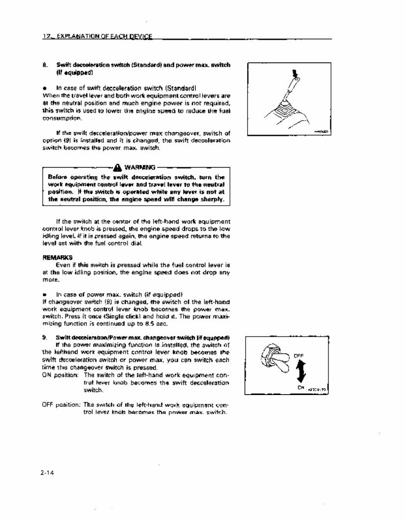
12. EXPLANATION OF EACH DEVICE
8. Swift decceleration switch (Standard) and power max. switch (if equipped]
0 In case of swift decceleration switch (Standard) When the travel lever and both work equipment control levers are at the neutral position and much engine power is not required, this switch is used to lower the engine speed to reduce the fuel consumption.
If the swift decceleration/power max changeover, switch of option (9) is installed and it is changed, the swift decceleration switch becomes the power max. switch.
Before operating the swift decceleration switch, turn the r - WARNING -7 work equipment control lever and travel lever to the neutral position. If the switch is operated while any lever is not at the neutral position, the engine speed will change sharply.
If the switch at the center of the left-hand work equipment control lever knob is pressed, the engine speed drops to the low idling level. If it is pressed again, the engine speed returns to the level set with the fuel control dial.
REMARKS Even if this switch is pressed while the fuel control lever is
at the low idling position, the engine speed does not drop any more.
0 In case of power max. switch (if equipped) If changeover switch (9) is changed, the switch of the left-hand work equipment control lever knob becomes the power max. switch. Press it once (Single click) and hold it. The power maxi- mizing function is continued up to 8.5 sec.
9. Swift decceleration/Power max. changeover switch (if equppedl If the power maximizing function is installed, the switch of
the lefthand work equipment control lever knob becomes the swift decceleration switch or power max. you can switch each time this changeover switch is pressed.
The switch of the left-hand work equipment con- trol lever knob becomes the swift decceleration
ON position:
OFF position:
OFF
z
switch.
The switch of the left-hand work equipment con- trol lever knob becomes the power max. switch.
I ON
Ai3QS170
2-l 4
https://tractormanualz.com

12. EXPLANATION OF EACH DEVICE
12.3 CONTROL LEVERS/ PEDALS
nE304620
1. Lock lever (for the left and right arm and boom apparatus control levers)
A Warning!
l Make sure that the lock lever is in the locked position when standing up from the operator’s seat. If you accidentally touch the lever and it is not locked serious injury may result.
l If the lock lever is not exactly in the locked position the control levers may not be locked. Make sure that the lever is in the position shown in the diagram.
A Warning!
0 The machine may be moved and the blade operated even though the lock lever is locked as they are not locked by this iever.
l Make sure that you do not touch the control levers for the arm and boom apparatus when pulling up the lock lever. It is dangerous if the lock lever is not pulled all the way to the top as the arm and boom apparatus may move or swing.
2-15
https://tractormanualz.com

12. EXPLANATlON OF EACH DEVICE
A Warning! ,-I
Be careful not to touch the control levers for the arm and boom apparatus when pushing the lock lever down.
This is a device which locks the arm and boom apparatus and prevents it from swinging. If the lever is pulled up, the lever stand will go up and lock.
This locking lever is a hydraulic type lock so that when placed in the locked position, the control levers for the arm and boom apparatus will move but the arm and boom apparatus itself and the swing motor will not.
A Warning!
The method of operating the control levers for the arm and boom apparatus and the movement of this apparatus is prescribed by JIS. The hydraulic hoses and the valves etc. may not be modified. 0 Prevent accidents from improper operetion. 0 7his does not conform to the directives of the Construction
Ministry.
2. Left arm and boom apparatus control lever
Thii lever controts the operation of the arm and the upper swing structure.
Arm operation Swing operation A Extend C Swing to right B Retract arm D Swing to left N (Neutral: The upper swing structure and arm will not move and
will be maintained in that same position.
3. Right am and boom appemtus control lever
This lever controls the operation of the boom and the bucket.
Boom operation Bucket operation 1 Raise 3 Dump 2 Lower 4 Biie N (Neutral: The boom and bucket will not move and will be
maintained in that same position.
4. FUEL CONTROL DIAL This dial is used to control the engine speed and output. @ Low idling position:
The dial is turned to the left kounterciockwisel @ High idling position:
The dial is turned to the right (clockwise)
2-16
https://tractormanualz.com

12. EXPLANATION OF EACH DEVICE
5. Blade control lever
This lever controls the blade.
1. Lower 2. Raise
6. Forward/ Reverse Travel lever
lever are reversed. Before using the forward/ reverse travel lever, make sure you know which way the track frame is facing. (When /
the sprocket is in the rear the track frame is facing forward) Sprocket -
1 Forward: Push the lever forward 2. Reverse: Pull the lever towards you Neutral position: The vehicle does not move either forward or in
reverse.
REMARK Machines equipped with travel alarm
If the lever is shifted to the advance or reverse position from the neutral position, the alarm sounds to warn that the machine is starting to advance. .-_ --___ .___ ._ _____ __
7. Pedal lock (for operating the boom offset)
A Warning!
When not operating the boom offset, keep it locked with the pedal lock. A serious accident can be caused if the pedaf for operating the boom offset is accidentally moved when it is not locked.
This is a device for locking the pedal for operating the boom offset.
The pedal is locked by covering it with a plate.
2-l 7
https://tractormanualz.com

12. EXPLANATION OF EACH DEVICE
8. Boom offset pedal
The boom is offset with this pedal 1. Right off set 2. Left offset
9. Travel speed accelerator
Pressing this pedal down accelerates the forward/ reverse travel speed.
2-18
https://tractormanualz.com

12. EXPLANATION OF EACH DEVICE
12.4 ENGINE HOOD
1. Raising engine hood release lever (11, unlocks the hood.
2. Pulling up on hood (2) will open it.
3. When closing the hood, quietly lower the hood and fasten the
lock.
NOTICE
Keep the hood locked at ail times other than when you need
to open it.
2-19
https://tractormanualz.com

12. EXPLANATION OF EACH DEVICE
12.5 FRONT WINDOW
A Warning!
Always grip the front window firmly with both hands when you open it. lf your hands slip when opening it they may be pinched between the window and the frame.
You may pull up and secure the front window (the top of it) to the roof of the cab.
When opening
A Warning!
When the front window is open there is the danger that it may fall so always lock it with the left and right lock pins.
1. Place the arm and boom apparatus down on level ground and stop the engine.
2. Lock the safety lock lever securely.
3. Disconnect the windshield wiper motor wires at outlet 3.
NOTICE
If you try to open the window but do not disconnect the wires from the outlet, the wires will be pulled out.
4. Pull the lock pins A on the top right and left sides of the window and release the locks.
1
2-20
https://tractormanualz.com
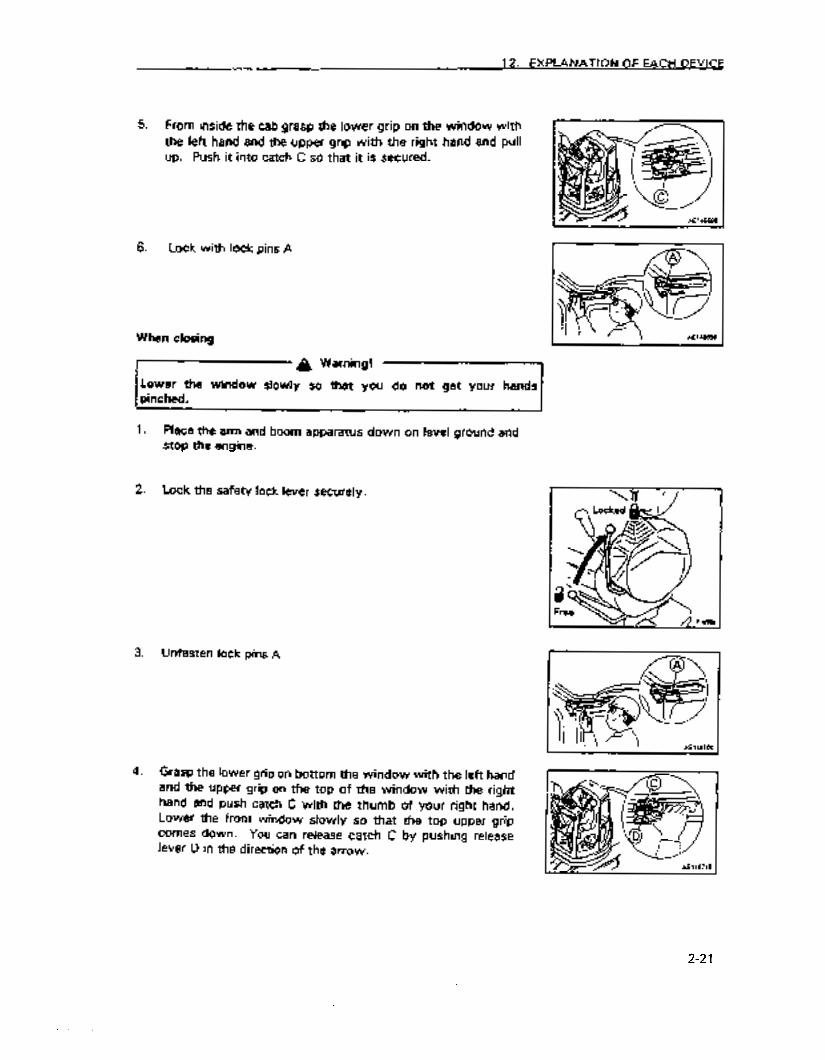
12. EXPLANATION OF EACH DEVICE
5. From inside the cab grasp the lower grip on the window with the left hand and the upper grip with the right hand and pull up. Push it into catch C so that it is secured.
6. Lock with lock pins A
When closing
r--J- A Warni”g! Lower the wmdow slowly so that you do not get your hands
1. Place the arm and boom apparatus down on level ground and stop the engine.
2. Lock the safety lock lever securely.
3. Unfasten lock pins A
4. Grasp the lower grip on bottom the window with the left hand and the upper grip on the top of the window with the right hand and push catch C with the thumb of your right hand. Lower the front window slowly so that the top upper grip comes down. You can release catch C by pushing release lever D in the direction of the arrow.
2-21
https://tractormanualz.com

12. EXPLANATION OF EACH DEVICE
5. Securely fasten lock pins A on the right and left of the window
6. Connect the windshield wiper motor wires at outlet B.
l Removing the front window (lower part)
You may remove the lower part of the front window when the top part of the front window is open by releasing lock pin E. Store this in the rear of the cab.
12.6 SLIDING DOOR
A Warning!
On vehicles that come with a cab always make sure that the slidin! door is locked whether the door is open or closed. Always open o close the door when you are on level ground. The force needed h open or dose the door on a slope may vary suddenly so avoid tryin! to open or dose it on a slope.
II * Dooi lo&k
Ii is very dangerous if tinkers are &ght in the &ding &Or. Open and dose the &ding door with its knob. When closing the sliding door, in particular, take care not to get Your fingers and hand caught between the door and the cab
..-
sr D II
9 I A
When closing the door, pull the handle initially back and release tfre lock then pull the door forward.
12.7 HAMMER FOR EMERGENCY ESCAPE. In case it becomes impossible to open the door, a hammer @
to be used for escape from the cab is installed.
When escaping, break the window glass with hammer 0.
NOTICE When escaping, remove the broken pieces of the glass from the
sash so that you will not cut yourself with them. Take care not to slip on the broken and scattered pieces.
2-22
https://tractormanualz.com

12. EXPLANATION OF EACH DEVICE
12.8 FUSE BOX
NOTICE
Always disconnect electrical power (turn the ignition switch to OFF) before changing fuses.
Fuses protect electrical equipment and wires from burning up and damage from excess heat.
If fuses have corroded, if they have white powder on them or if they have become loose in the fuse holder, replace them.
Use fuses of the same capacity when replacing.
Fuse capacity and name of circuit
No. Fuse Capacity Name of Circuit
1 30 A Engine control system
2 20 A Electrical system controller, Monitor panel, knob switch (if equipped) -
3 20 A Electrical system redundant circuits - -
Heater, horn, windshield wipers, 4 30 A interior light, radio, auto diesel -
motor
Operating light, reset power, car cooler (if equipped), swing brake,
5 30 A buzzer, TVC solenoid valve, forward/reverse travel accelerator solenoid valve
12.9 FUSIBLE LINK
When the ignition switch is turned to the ON position and there is no power, it may be a broken wire-type fusible link 2 so open up side cover 1 on the left side of the body and check and replace it if necessary.
Additional explanation
A fusible link refers to the large fuse circuit installed in circuits which have high current flows. Similar to ordinary fuses, it protects electrical equipment and circuits from burning up from unusually heavy flows of current.
2-23
https://tractormanualz.com

12. EXPLANATION OF EACH DEVICE
12:,10 LOCKING CAP AND COVERS
The fuel tank cap, the cab, the engine hood, the left side cover and right side cover are all outfitted with locks.
Use the ignition switch key to remove and replace the fuel xankcep.
i 2.10.1 How to remove and replace the locking cap for refueling the fuel tank
n To remove
1. Insert the key
2. Turn the key in a counterclockwise direction and align the opening of the rotor groove with the mark on the cap and YOU may remove the cap.
n To lock
1. Screw in the cap.
2. Turn and remove the key.
Turn the key only after fully inserting it. If you turn it when not fully inserted, you may bend and damage the key.
12310.2 How to open and close covers with locks
n To open (when they are focked)
1. insert the key.
2. Turn the key in a counterclockwise direction, and if you can grasp the cover handle you can open it.
n To lock
1 - Close the cover and insert the key.
2. Turn the key in a clockwise direction and remove it.
12.11 MANUAL POCKET The operator3 seat has a manual pocket in rhe back of backrest. This manual should be kept in it for reference atid periodical
reviewing.
Shoulder
1 - Al301320
2-24
https://tractormanualz.com

12. EXPLANATION OF EACH DEVICE
12.12 TOOL BOX
Place tools in this.
12.13 GREASE GUN HOLDER
Thii is inside the battery compartment [on the left side of the vehicle). Hang the grease gun in here when not using it.
? 2.14 CONTROLLERS
Controllers for controlling the arm and boom apparatus are installed.
NOTICE
0 Do not allow water, mud or drinlcs to get on the controlks as this will cause breakdowns.
0 If problems arise with the controllers, do not attempt to repair them your&f. Consult with Komatsu or your Komatsu dealer.
12.15 ASHTRAY (if equipped)
This is on the right side of the cab. Always close the cover after extinguishing cigarettes.
12.16 REAR UNDER VIEW MIRROR
Sit in the operatofls seat, and adjust the mirror so that you can see behind the counterweight.
NOTlCE
The mirror may protrude from the swing radius (approximately 100 mm) depending on the direction.
2-25
https://tractormanualz.com

12. EXKANATION OF EACH DEVICE
12.17 USING THE CAR RADIO
1217.1 Explanation of each feature
ttnrr
1. ON/OFF and volume controf button (push ONNOLI
Turn the radio on by pressing this button. tights will come on on the display panel and the frequency (1) will be displayed. Pressing this button will turn off the power to the radio.
Turning the button in a clockwise direction when the radio is on wiil increase the volume. Turning it in a counter clockwise direction will decrease volume.
2. Tone qua&y control button (TONE)
Turning this button in a clockwise direction from the neutral position will enhance the treble sounds. Turning it in the opposite direction will enhance the bass sounds.
3. Display button WiSPI
If you push this button while the radio is on, the set frequenw being received will be displayed for 5 seconds.
1 rncn
2-26
https://tractormanualz.com

12. EXPLANATlON OF EACH DEVICE
4. Channel selection, time set buttons (TUNE)
When selecting channels, change frequency using these
buttons. Each time the up-button A is pressed, frequency increases 9 kHz, and each time the down-button v is pressed,
frequency decreases 9 kHz. If these buttons are pressed
continuously for more than 2 seconds the channel selector will
automatically scan and select a channel. These buttons are also
used to change the hour and second displayed when setting the
clock.
5. Preset buttons (1.2,3,4+61
You may select a desired channel by pressing a button when
these buttons have been set to desired channels in advance.
6. Timesetbutton CT.AlW
Press this button to ser the time
7. Time information button (RESET)
If you press this butron you can reset the clock to 0.
8. Display panel
Displays the frequency, the time and the preset numbers.
f l?lQ
2-27
https://tractormanualz.com

12. EXPLANATION OF EACH DEVICE .
12.17.2 How to operate the radio
n
1.
2.
3.
How to set the preset buttons
Press the ON/OFF switch. The frequency will be displayed in the display section.
Adjust the channel select buttons (A or VI to the desired frequency.
Press buttons of the number you wish to store in memory continuously for at least 2 seconds. When the sound dies out and then resounds, the number has been entered in memory and the preset number will be diitayed in display section 2.
After the number has been stored and the preset button is pressed and released (less than 2 seconds) the frequency of the broadcast station that was stored with that rrumber wiii be heard.
One station may be stored for each preset button.
n How to tune manudly
Press the channel select buttons gently and select the desired frequency. Each time the button is pressed the frequency changes 9 kHr.
button: Moves in the direction of higher frequencies button: Moves in the direction of lower frequencies
How to select automsticaay
Press the channel select button continuously for at least 2 seconds and release. When a broadcast channel is detected the scan will automatically stop on that channel.
To search for the next channel again press the channel select button continuously for at reast 2 seconds and release.
A button: Moves in the direction of higher frequencies V button: Moves in the direction of lower frequencies
When the signal of the channel is weak and is not selected, find the channel manually.
2-28
https://tractormanualz.com

12. EXPLANATION OF EACH DEVICE
a
1.
2.
n
Setting the time
While pressing the time set button (I), press the button for setting the hour (2). The hour displayed will change so when the hour you wish to have displayed appears, release the button.
While pressing the time set button (‘I), press the button for setting the minute (3). The minute displayed will change so when the minute you wish to have displayed appears, release the button.
How to use the clock reset button
To set the clock with a time signal announcement or to standard time, press the reset button (11, and the clock will instantly show the correct hour. From 1 to 29 minutes after the hour, the time will go back to the hour. From 30 to 59 minutes after the hour, the time will move forward to the next hour.
Example:
lo:29 + 1O:OO (goes back) IO:30 -, 11:OO (goes forward)
m Antenna
Extend the antenna when the signal is weak or when there is static. When set to a strong signal, retract the antenna and adjust to a weaker signal.
NOTICE
Retract antenna prior to transporting the vehicle, or putting it in a garage so that it will not get in the way.
2-29
https://tractormanualz.com
12. EXPLANATION OF EACH DEVICE
12.17.3 Precautions in using
For purp&es of safety, while operating the machine, adjust
the volume level so that sounds outside the vehicle are audible. Be careful so that water does not get on the speaker cases or in the car radio (auto tuning) because this will cause malfunctioning. Never use solutions such as benzine or thinners ,to clean the dial or buttons. These should be cleaned with a soft, dry cloth. (Use a cloth dipped in alcohol for extremely soiled surfaces). Reset preset settings after replacing the battery as all of them will be deared when the battery is removed.
12.17.4 Specifications
Tuning system: PLL synthesizer system Receiving frequencies: ‘522 kHz - 1629 kHt Intermediate frequency: 450 kHr Rated output: 3w Maximum output: 5w Current consumed: less than 2 A External dimensions: width, 176 mm; height, 50 mm; depth
110 mm Weight: 6mg
2-30
https://tractormanualz.com
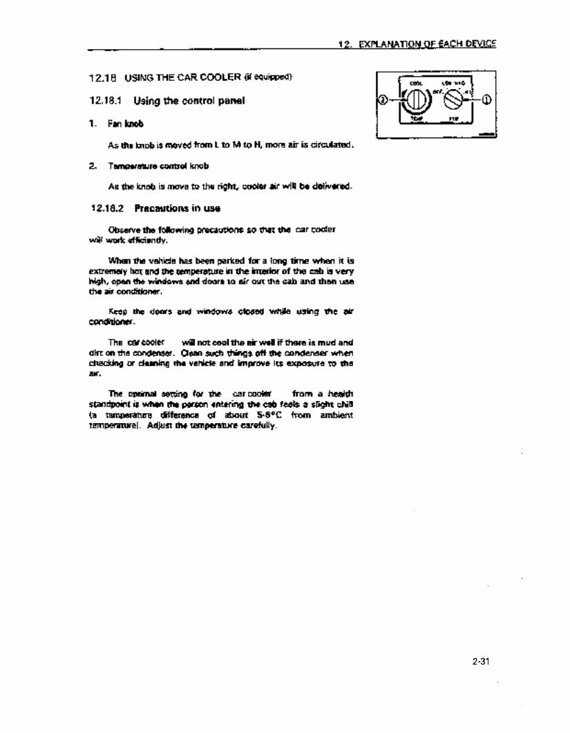
12. EXPLANATION OF EACH DEWCE
12.18 USING THE CAR COOLER (if equipped)
1218.1 Using the control panel
1. Fan knob
As the knob is moved from L to M to H, more air is circulated.
2. Temperature control knob
As the knob is move to the right, cooler air will be delivered.
12.18.2 Precautions in use
Observe the following precautions so that the car cooler wilt work efficiently.
When the vehicle has been parked for a long time when it is extremely hot and the temperature in the interior of the cab is very high, open the windows and doors to air out the cab and then use the air conditioner.
Keep the doors and. windows closed while using the air conditioner.
The. car cooler will not cool the air well if there is mud and dirt on the condenser. Clean such things off the condenser when checking or deaning the vehicle and improve its exposure to the air.
The optimal setting for the car cooler from a health standpoint is when the person entering tie cab feels a slight chili (a temperature difference of about 5-8OC from ambient temperatureI. Adjust the temperature carefully.
2-31
https://tractormanualz.com

13. OPERATION
13.1 CHECKS BEFORE STARTING THE ENGINE
13.1.1 Visual check
Before starting the engine visually inspect the environs and
under side of the vehicle to see if there are any loose bolts and
nuts, oil or fuel leaks and check the condition of the arm and boom
apparatus and the hydraulic system. Check to see if there are any
loose wires, messy spots or accumulations of dust in places where
the temperature will likely be high.
A Warning!
Accumulation of flammabie material near the battery and engine
components that run at high temperatures like the muffier and
turbo’s and leaks of fuel and oil may cause fires in the vehicle.
Check carefully and if there is a problem, always correct it or
contact Komatsu or your Komatsu distributor.
Perform the checks in this’ section once daily prior to starting
the engine.
L
1. Check the sensors for damage
Check the sensors for damage and if anything is abnormal
have it inspected and repaired by Komatsu or your Komatsu
distributor.
2. Check the arm and boom apparatus, cylinders, linkage and
hoses for damage, wear and play.
Check the arm and boom apparatus, cylinders, linkage and
hoses for cracks and excessive wear and play. If any thing is
wrong have it repaired.
2-32
https://tractormanualz.com
13. OPERATION
3. Remove dirt and dust from around the engine, battery and radiator.
Check to see whether any dust or dirt has accumulated around the engine and radiator. Also check to see if any. flammable materials (dead leaves, twigs etc.) are near the battery and engine components that run at high temperatures like the muffler and turbocharger. Get rid of all dust or accumulations of flammable materials found.
4. Check to see if there are any water leaks or fuel leaks around the engine.
Check to see if there are fuel leaks from the engine or any water leaks from the cooling system. If anything is wrong have it repaired.
5. Check for leaks from the hydraulic equipment, the hydraulic tank, hoses and joints.
Check to see whether there are any oil leaks and if anything is wrong have it repaired.
6. Check the undercarriage (the tracks, sprocket and idler) for damage, wear, loose bolts and oil leaks from the rollers.
7. Check the handrails for loose bolts
If anything is wrong have it repaired. Tighten UP loose bolts.
8. Check the gauges and monitors for damage and loose bolts.
Check to see whether there is any damage to gauges and monitors and if anything is wrong replace them. Clean the surfaces of these gauges and monitors so that they are free from dirt and grime.
9. Check and clean the rear under view mirror (optional)
Check for damage to the rear underview mirror and if there is damage replace it with a new one. Make sure that the surface of the mirror is clean and adjust the mirror so that the lower part of the rear of the vehicle is visible from the operator’s seat.
IO. Check seat belts and fastening hardware (optional).
Check seat belts and fastening hardware and if there is damage, replace them with new ones.
11. Check to make sure that the window is in place and not damaged
Check to make sure that the window is in place and not damaged. If damaged replace it with a new one. If the window comes off or is damaged during operations, do not continue operations. Repair it or restore it immediately.
2-33
https://tractormanualz.com

13.12 Checks before beginning operations
Perform these checks once daily prior to starting the engine the first time.
Check the coolant level and add if necessary
Do not remove the radiator cap. When the engine is cold. coolant
1.
2.
3.
a
1.
2.
3.
4.
Open the engine hood and check to see whether the coolant level in the reserve tank (1) is between FULL and LOW. If the level is low add coolant to reserve tank (1) until it is at the full level.
Tighten the cap securely when you have finished adding coolant.
If the reserve tank ie empty check for leaks. Then check the coolant level in the radiator. If low add coolant to the radiator and then to the reserve tank.
Check the oil in tt~e engine oil pan and add if needed.
Open tie engine hood
Remove dipstick (G) and wipe it off with a rag.
Reinsert dipstick (%I as far as it will go and then remove..
tf there is oil on the dipstick (G) between H and L, the level is satisfactory. If the level is below L add oil at (R.
For the oil to use see item 21, “Use of fuel and lubricants by ambient temperatures”.
2-34
https://tractormanualz.com
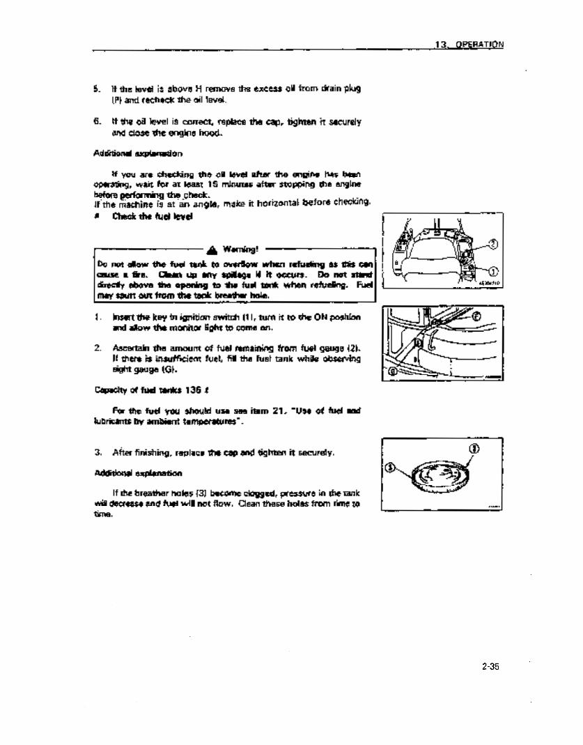
13. OPERATION
5. If the level is above H remove the excess oil from drain plug (PI and recheck the oil level.
6. If the oil level is correct, replace the cap, tighten it securely and close the engine hood.
Additional explanation
If YOU are checking the oil level after the engine has been operating, wait for at least 15 minutes after stopping the engine before performing thq,_Gheck. If’the r&chine is at an angle, make it horizontal before ch=kiw. a CM the fud levd
directly above the opening to the fuei tank when refuting. Fuel 1 may spurt out from the tank breethu hoJt_
1. Insert the key in ignition switch (1 I, turn it to the ON position and allow the monitor light to come on.
2. Ascertain the amount of fuel remaining from fuel gauge (2). ff there is insufficient fuel, fift the fuel tank white observing sight gauge (G).
Capacity of fuel tanks 135 I
For the fuel you should use see item 21, “Use of fuel and lubricants by ambient temperatures”.
3. After finishing, replace the cap and tighten it securely.
Additional explanation
If the breather holes (3) become clogged, pressure in the tank will decrease and fuel will not flow. Clean these holes from time to time.
2-35
https://tractormanualz.com
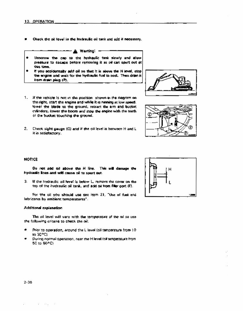
n Check the oil level in the hydraulic oil tank and add if necessary.
a Warning!
0 Unscrew the cap to the hydraulic tank slowly and allow pressure to escape before removing it as oil can spurt out al this time.
0 If you accidentally add oil so that it is above the H level, stop the engine and wait for the hydraulic fuel to cool. Then drain it from drain plug (PI.
1. If the vehicle is not in the position shown in the diagram on the right, start the engine and while it is running at low speed, lower the blade to the ground, retract the arm and bucket cylinders, lower the boom and stop the engine with the teeth of the bucket touching the ground.
2. Check sight gauge (G) and if the oil level is between H and L it is satisfactory.
NOTICE
Do not add oil above the H line. This will damage the hydraulic lines and will cause oil to spurt out.
3. If the hydraulic oil level is below L, remove the cover on the top of the hydraulic oil tank, and add oil from filler port (F).
For the oil you should use see lubricants by ambient temperatures”.
Additional explanation
item 21, “Use of fuel and
The oil level will vary with the temperature of the oil so use the following criteria to check the oil:
0 Prior to operation, around the L level (oil temperature from 10 to 3ooc1
0 During normal operation, near the H level (oil temperature from 50 to 80°C)
2-36
https://tractormanualz.com
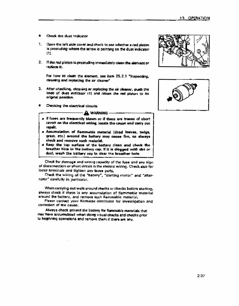
13. OPERATION
a Check the dust indicator
1. Open the left side cover and check to see whether a red piston is protruding where the arrow is pointing on the dust indicator (1).
2. If the red piston is protruding immediately dean the element or replace it.
For how to clean the element see item 25.2.1 “Inspecting, cleaning and replacing the air cleaner”
3. After checking, cleaning or replacing the air cleaner, push the knob of dust indicator (1) and return the red piston to its original position.
a Checking the electrical circuits
,-- g WARNING
If fuses are frequently blown or if there are traces of short circuit on the electrical wiring, locate the cause and carry out repair. Accumulation of flammable material (dead leaves, twigs, grass, etc.) around the battery may cause fire, so always check and remove such material.. Keep the top surface of the battery clean and check the breather h&e in the battery cap. If it is clogged with dirt or dust, wash the battery cap to clear the breather ho(e.
Check for damage and wrong capacity of the fuse and any sign of disconnection or short circuit in the electric wiring. Check also for loose terminals and tighten any loose parts.
Check the wiring of the “battery”, “starting motor” and “alter- nator” carefully in particular.
When carrying out walk-around checks or checks before starting, always check if there is any accumulation of flammable material around the battery, and remove such flammable material.
Please contact your Komatsu distributor for investigation and correction of the cause.
Always check around the battery for flammable materials that may have accumulated when doing visual checks and checks prior to beginning operations and remove them if there are any.
2-37
https://tractormanualz.com
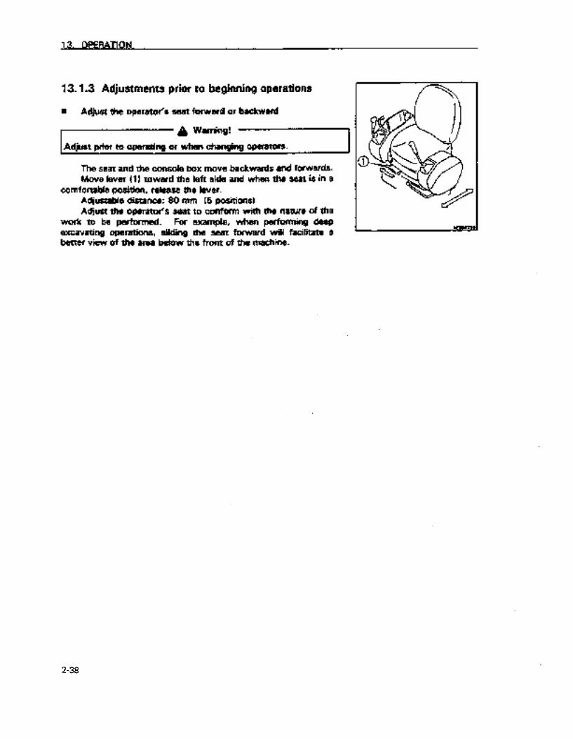
13.1.3 Adjustments prior to beginning operations
w Adjust the operator’s seat forward or backward
A Warning!
Adjust prior to operating or when changing operators.
The seat and the console box move backwards and forwards. Move lever (1) toward the left side and when the seat is in a
comfortable position, release the lever. Adjustable distance: 80 mm (5 positions) Adjust the operator’s seat to conform with the nature of the
work to be performed. For example, when performing deep excavating operations, sliding the seat forward will facilitate a better view of the area below the front of the machine.
2-38
https://tractormanualz.com
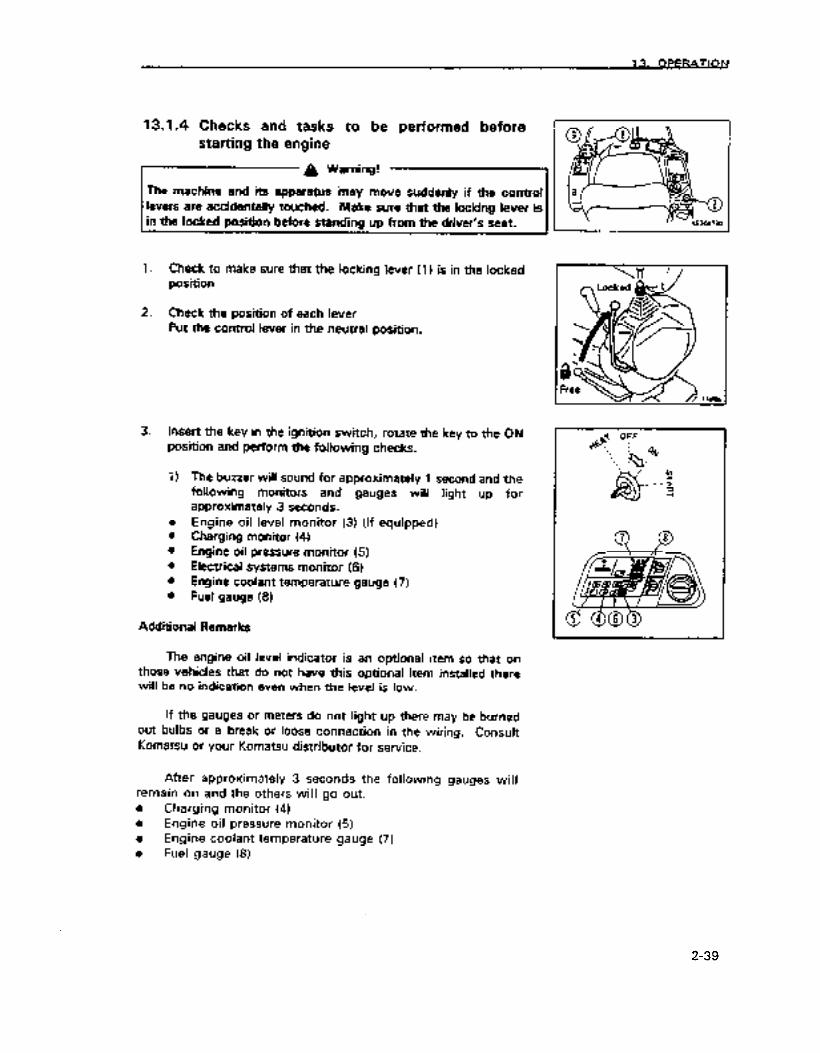
13.1.4 Checks and tasks to be performed before starting the engine
A Warning!
The machine and its apparatus ‘may move suddenly if the control levers are accidentally touched. Make sure that the locking lever is in the locked position before standing up from the driver’s seat.
1. Check to make sure that the locking lever (1) is in the locked position
2. Check the position of each lever Put the control lever in the neutral position.
3. Insert the key in the ignition switch, rotate the key to the ON position and perform the following checks.
1) The buzzer will sound for approximately 1 second and the foliowing monitors and gauges will light up for approximately 3 seconds.
l Engine oil level monitor (3) (if equipped) l Charging monitor (4) l Engine oil pressure monitor (5) l Electrical systems monitor (6) l Engine coolant temperature gauge (7) l Fuel gauge (8)
Additional Remarks
The engine oil level indicator is an optional item so that on those vehicles that do not have this optional item installed there will be no indication even when the level is low.
If the gauges or meters do not light up there may be burned out bulbs or a break or loose connection in the wiring. Consult Komatsu or your Komatsu distributor for service.
After approximately 3 seconds the following gauges will remain on and the others will go out. 0 Charging monitor (4) 0 Engine oil pressure monitor (5) a Engine coolant temperature gauge (7) l Fuel gauge (8)
2-39
https://tractormanualz.com

21 Turn the light switch (9) in a clockwise direction and check to see whether the lights come on.
If the lights do not come on there may be burned out bulbs or a break or loose connection in the wiring. Consult Komatsu or your Komatsu distributor for service.
3) Push the horn switch (IO) and check that the horn sound&
2-40
https://tractormanualz.com
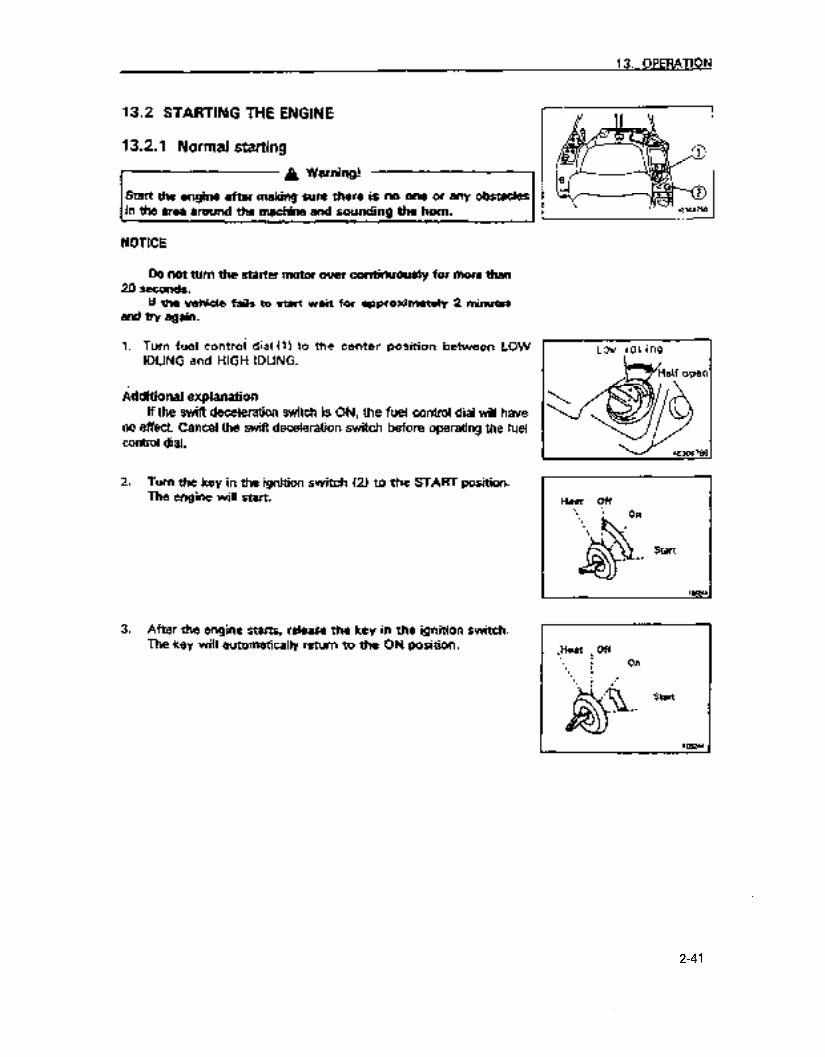
13. OPERATION
13.2 STARTING THE ENGINE
13.2.1 Normal starting
g Warning!
Start the engine efter making sure there is no one or eny ‘obstedes in the area around the mechine and sounding the ‘horn.
NOTICE
Do not turn the starter motor over continuously for more than 20 seconds.
If the vehide faiis to start wait for approximatety 2 minutes and try again.
1. Turn fuel control dial (1) to the center position between LOW IDLING and HIGH IDLING.
Additional explanation If the swift deceleration switch is ON, the fuel control dial will have
no effect. Cancel the swift deceleration switch before operating the fuel control dial.
2. Turn the key in the ignition switch (21 to the SART position. The engine will start.
3. After the engine starts, reiease the key in the ignition switch. The key will automatically return to the ON position.
4
Low iclling
Heat yf ‘\ 1
‘. Oil
*. , . I
& a / Start _ --
,Hsat : Off . I : I On
Start *.
2-41
https://tractormanualz.com

13.2.2 Starting in Cold Weather
A Warning!
Start the engine after making sure there is no one or any obstades in the area around the machine and sounding the horn.
NOnCE
Do not turn the starter motor over continuousiy for more than 20 seconds.
if the vehicle fails to start wait for approximateiy 2 minutes and try again.
Start the engine with the following procedure in cold weather
1. Turn fuel control dial 111 to the center position between LOW IDLING and HIGH IDLING.
Additional explanation If the swift deceleration switch is ON, the fuel &ntrol dial will have
no effect. Cancel the swift deceleration switch before operating the fuel control dial.
2. Turn the key in the ignition switch (21 to the HEAT (preheatI position and make sure that the preheat monitor light (31 comes on. After approximately 18 seconds the preheat monitoring liiht will go out signaling that preheating has been completed.
Additional explanation
When the key is placed in the HEAT posit&, monitor and gauge lights will come on but this does not indicate that anything is wrong.
3. When the preheat monitor light (3) goes out, place the key in the starting switch (2) in the START position and start the machine.
4. After the engine starts, release your grip on the key in starting switch (2). The key will automatically return to the ON position.
L
2-42
https://tractormanualz.com
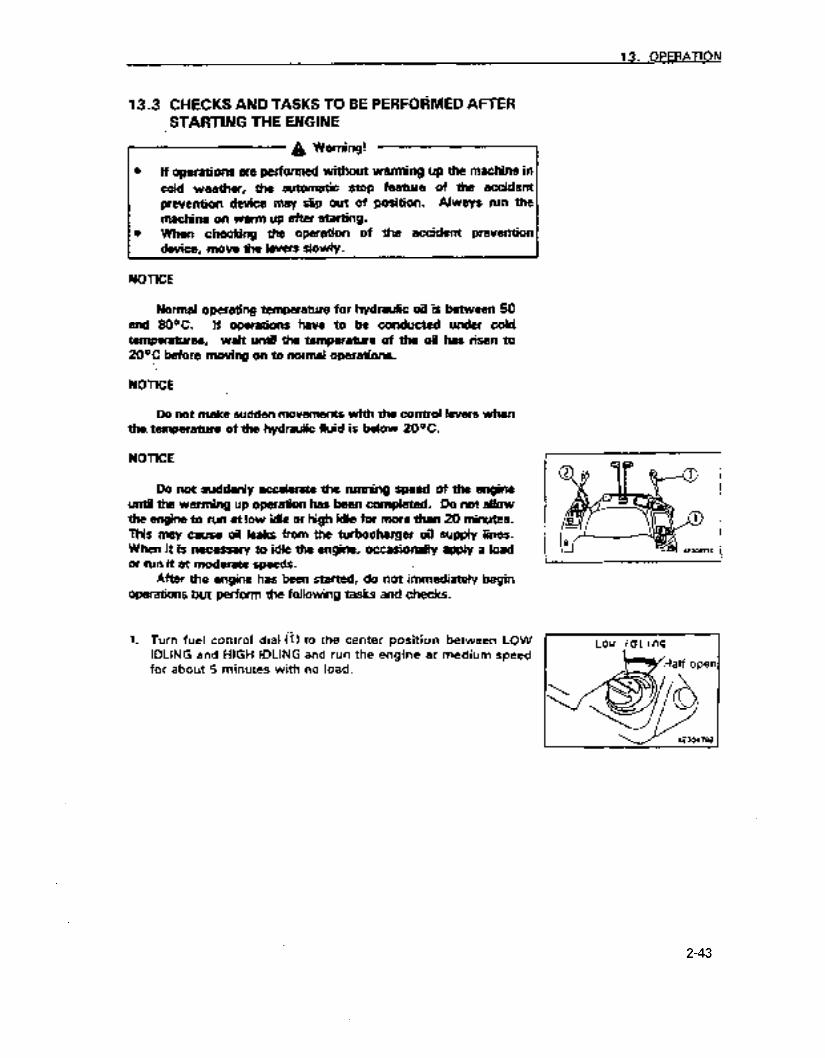
13.3 CHECKS AND TASKS TO BE PERFORMED AFTER STARTING THE ENGINE
I- g Warning!
a If operations are perFormed v&out warming up the machine in cold weether, the eutometic stop feature of the accident prevention device may slip out of position. Always run the machine on warm up after starting.
l When checking the operation of the accident prevention device, move the levers slowly.
NOTICE
Normal operating temperature for hydraulic oil is between 50 and 8OOC. If operations have to be conducted under coid temperatures, wait until the temperature of the oil has risen to 20°C before moving on to normal operations.
NOTICE
Do not make sudden movements with the control levers when the. temperature of the hydraulic fluid is below 20°C.
NOTlCE
Da not suddenly accelerate the running speed of the engine until the warming up operation has been completed. Do not allow the engine to run at low idle or high idle for more than 20 minutes. This may cause oil leaks from the turbocharger oil supply lines. When it is necessary to idle the engine. occasionaMy appiy a load or run it 8t moderate speeds.
After the engine has been started, do not immediately begin operations but perform the following tasks and checks.
1. .-.
Turn fuel control dial (11 to the center position. between LOW IDLING and HIGH iDLiNG and run the engine at medium speed for about 5 minutes irvith no load.
I
Low icll inQ
2-43
https://tractormanualz.com

2.
3.
4.
l
0 0 0 0 0
5.
6.
7.
Set the locking lever (2) to the free position and raise the bucket from the ground.
Move the right arm and boom apparatus control lever (3) slowly and move the bucket cylinder to the end of the stroke and maintain it there for 5 minutes.
After warming up the machine, make sure that each of the monitor lamps and gauges are as follows:
Engine coolant temperature gauge (4) . . . In the green range Fuel gauge (5) . . . . _ . . . . . . . . . . . . . . In the green range Engine oil pressure monitor (6) . . . . . . . . . . . . . tight is out Charge level monitor (7) . . . . . . . . . . . . . . . . . tight is out Engine oil level monitor (8) . . . . . . Light is out (if equipped) Electrical system monitor (9) . . . . . . . . . . . . . . Light is out
Make sure there. is no abnormal color to the exhaust gas, unusual sounds or vibrations. If something is abnormal repair it.
Place the locking lever (2) in the locked position and make sure that the arm and boom apparatus cannot be operated with the left and right control levers and that it cannot be swung.
Place the locking lever (2) in the free position and check the accident prevention device as follows.
2-44
https://tractormanualz.com

Place the arm and boom apparatus in the position as shown in the diagram to the right, raise the boom and move it so that you can see whether the apparatus automatically stops when it approaches the cab. If it stops, lower the boom and turn off
the automatic stop feature.
Place the arm and boom apparatus in the position as shown in the diagram to the right, move the arm toward the cab and move it so that you can see whether the apparatus automatically stops when it approaches the cab. If it stops, extend the arm and turn off the automatic stop feature.
Place the arm and boom apparatus in the position as shown in the diagram to the right, operate the left offset to see whether the apparatus automatically stops when it approaches the cab. If it stops, operate the right offset and turn off the automatic stop feature.
When checking and there seems to be something abnormal, perform task 3 (Move the right arm and boom apparatus control lever slowly and move the bucket cylinder to the end of the stroke and maintain it there for 5 minutes), warm up the hydraulic fluid and try again.
If the problem continues to occur, stop the vehicle in a safe place, stop the engine, and request that Komatsu or your Komatsu distributor check and inspect it.
2-45
https://tractormanualz.com

13.4 MOVING THE MACHINE
13.4.1 Moving the machine forward
A Warning! .p
l Ascertain the direction of the track frame before operating the forward/ reverse travei levers. If the sprocket is at the front, the operation of the forward/ reverse travel levers is reversed.
0 Make sure that the area around the machine is safe and sound the horn before moving it.
0 Do not allow personnel near the machine. l Clear obstacles from the path of the machine.
‘1. Turn fuel control dial (11 towards the high idling position to 8
increase the engine speed.
Additional explanation If the engine speed does not rise, it is possible that the swifl
deceleration switch is ON. Check the knob switch on the left work equipment control lever.. For details of operation of ?he swift &ce!eration switch, see “62.2
SWITCHES”.
2. Place the locking iever (21 in the free position, retract the arm and boom apparatus and raise it 40 to 50 cm off the ground.
3. Raise the blade.
4. Operate tie right and left forward/ reverse travel control levers as follows:
l When the sprocket is at the rear of the machine
Move lever (31 forward slowly to move the machine.
l When the sprocket in at the front of the machine
Move lever (3) back slowly to move the machine.
2-46
https://tractormanualz.com

5. If travel speed accelerator pedal (4) is depressed, the travel speed will increase_ 2.4 km/h i+ 4.0 km/h (engine at full throttle)
13.4.2 Moving the machine backward
A Warning! ._I
l Ascertain the direction of the track frame before operating the forward/ reverse travel ievers. If the sprocket is at the front, the operation of the forward/ reverse travel levers is reversed.
a Make sure that the area around the machine is safe and sound the horn before moving it.
0 Do not allow personnel near the machine. 0 Clear obstacles from the path of the machine. 0 There is a blind spot behind the machine so when moving in
reverse exercise extreme caution.
1. Turn fuel control dial (1) towards the high idling position to increase the engine speed.
Additional explanation If the engine speed does not rise, it is possible that the swift
deceleration switch is ON. Check the knob switch on the left work equipment control lever. For details of operation of the swift deceleration switch, see “12.2
SWITCl-fES”.
2. Place the locking lever (2) in the free position, retract the arm and boom apparatos and raise it 40 to 50 cm off the ground.
3. Raise the blade.
2-47
https://tractormanualz.com
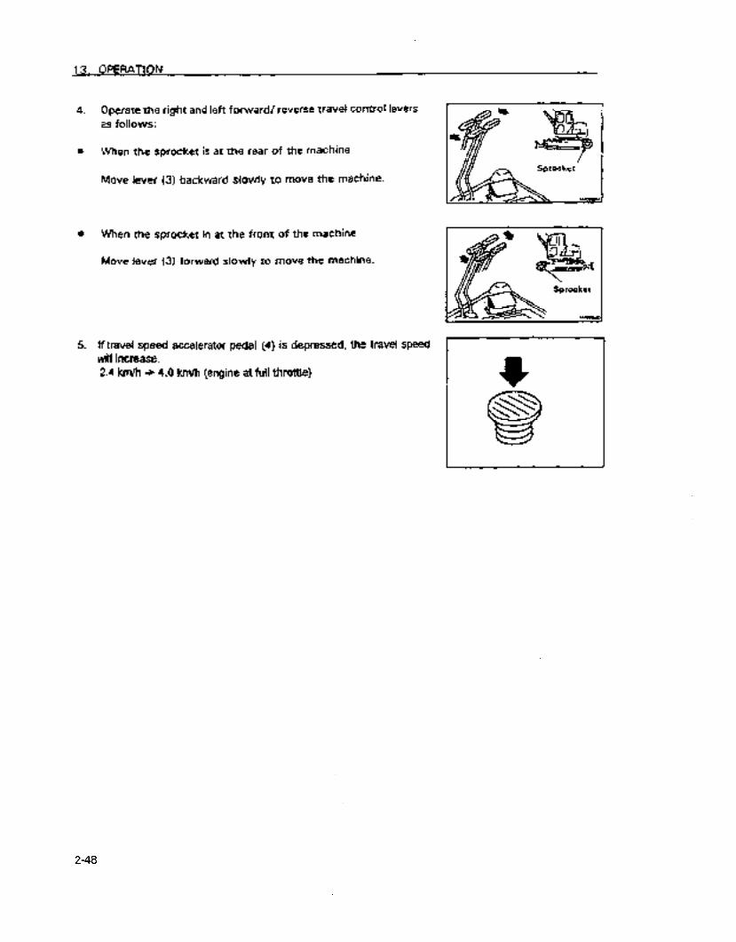
4. Operate the right and left forward/ reverse travel control levers as follows:
l When the sprocket is at the rear of the machine
Move lever (3) backward slowly to move the machine.
l When the sprocket in at the front of the machine
Move lever (3) forward siowly to move the machine.
5. ff travel speed accelerator pedal (4) is depressed, the travel speed will increase. 2.4 km/h + 4.0 km/h (engine at full throttle)
I+
2-48
https://tractormanualz.com

13. OPERATION
13.5 STEERING THE MACHINE
13.5.1 Steering (changing the direction of advance)
A Warning!
Ascertain the direction of the track frame before operating the forward/ reverse travel levers. If the sprocket is at the front, the operation of the forward/ reverse travel control levers is reversed.
Operate the forward/ reverse travel control levers to change direction.
As much as possible avoid sudden changes of direction. Particularly when executing counter rotation (spin turns), stop
the machine first and then change direction. Operate the two forward/ reverse travel control levers as
foilows:
n Changing the direction of the machine when it is not moving
When turning to the left, push the right travel control lever forward. Pulling that lever back will make turn the vehicle left in reverse.
Additional explanation
When turning to the right operate the left travel control lever in the same way.
w Changing the direction of the machine when traveling (when both the left and right forward1 reverse travel control levers are inclined in the same direction
To turn left, return the left travel control lever to the neutral position and the machine will turn left.
Additional explanation
When turning to the right operate the left travel control lever in the same way.
Forward left turn
Reverse left turn
https://tractormanualz.com

m When executing spin turns
To execute a spin turn to the left pull the left travel control lever back and push the right travel control lever forward.
Additional explanation
To execute a spin turn to the right pull the right travel control lever back and push the left travel control lever forward.
2-50
https://tractormanualz.com

13.6 STOPPING THE MACHINE
A Caution!
Avoid stopping suddenly and allow yourself ample room to stop.
A Warning!
0 Choose a firm level place to stop. 0 Do not stop on slopes. l When you must park the machine on a slope, block
the tracks so that they will not move and thrust the bucket into the ground. 1
A Warning!
The machine and its apparatus may move suddenly if the control levers are accidentally touched. Make sure that the locking lever is in the locked position before standing up from the driver’s seat. 4
1. Place the right and left forward/ reverse travel control levers in the neutral position. The machine will stop.
2-51
https://tractormanualz.com

13.7 SWINGING
a Warning!
Check to make sure that the area is safe before swinging the arm and boom apparatus.
1. Operate the left arm and boom apparatus control lever to swing it
2. When not swinging the apparatus, bring the superstructure and track frame into parallel and place the left arm and boom apparatus control lever (1) in N (neutral). The swing brake will engage.
2-52
https://tractormanualz.com

13. OPERATION
13.8 PROHIBITED ACTIONS WHILE OPERATING THE MACHINE
7 A Warning!
1 If you must operate the control levers for the arm and boom ‘apparatus while traveling, stop traveling temporariiy and then operate the arm and boom apparatus.
n Do not use the swing power of the machine in operations.
Never use the arm and boom apparatus while it is swinging to level ground, knock down mud walls or dig the teeth of the bucket into the ground whiie swinging the apparatus. You will damage the arm and boom apparatus if you do.
m Do not use the forward1 reverse travel power in operations.
inordinate strain is placed on the body of the machine if you try to excavate by moving the vehicle while the bucket is in the ground.
n Be careful of operations done at the end of the stroke of the hydrauiic fluid cylinder
If the arm and boom are operated when the cylinder is at the end of its stroke, considerable strain is placed on the stopper inside the cylinder and this wiil shorten the life of the machine. Allow a certain amount a space at the end of the stroke.
a Never use the dropping force of the bucket
Do not use the dropping force of the arm and boom apparatus for excavating or use the bucket for work that would be done by a pick axe or jack hammer or use the bucket to pound in pilings or stakes as this will place inordinate stress on the body of the vehicle. This will not only damage the body, it is also dangerous.
a Never use the dropping force of the body of the machine
Do not use the dropping force of the body of the machine.
2-53
https://tractormanualz.com

I Excavating hard pan
Excavating hard pan after breaking it up by some other means will cause less damage to the machine and is more cost-effective.
l Do not perform hoisting operations
Using this machine to perform hoisting operations is prohibited by the Labor Safety and Hygiene regulations.
The exception which is approved is the removal of pilings and when thii is to be done special fiings for hoisting are necessary.
Consult with Komatsu or your Komatsu distributor for details.
n Be careful of striking objects with the biade
Do not allow the biade to strike rocks and rock piles etc. This will cause damage to the blade and to the cylinders.
n Be careful when retracting the arm and boom apparatus
When retracting the boom for moving or for transporting the machine be careful so that the bucket and blade do not strike each other.
n Support both sides of the blade
When using the blade as an outrigger, do not support only one side of the blade.
m Be careful not to hit the bfade when doing deep excavation
When the blade is in front and performing deep excavation make sure that the boom cylinders do not strike the blade and other than when necessary perform deep excavation operations with the blade at the rear of the vehicle.
2-54
https://tractormanualz.com

n Be careful that the arm cylinder does not hit any obstacles
When the arm is moved, the varies. Be careful so that it does or contact anything unintended.
rear position of the arm cylinder not get hung up on power lines
I
(I)
(2)
(3)
Do not move the travel speed control lever suddenly when accelerating speed.
Do not move the lever suddenly so that the machine lurches forward. Do not move the lever suddenly when going from forward to reverse (or from reverse to forward) Do not move the lever suddenly (by releasing the lever suddenly) so that a sudden stop occurs when the vehicle is traveling at maximum speed.
2-55
https://tractormanualz.com
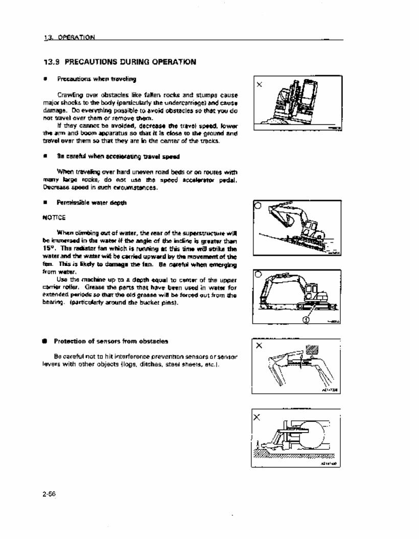
13.9 PRECAUTIONS DURING OPERATION
n Precautions when traveling
Crawling over obstacles like fallen rocks and stumps cause major shocks to the body (particularly the undercarriage) and cause damage. Do everything possible to avoid obstacles so that you do not travel over them or remove them.
if they cannot be avoided, decrease the travel speed, lower the arm and boom apparatus so that it is close to the ground and travel over them so that they are in the center of the tracks.
m Be careful when accelerating travel speed
When traveling over hard uneven road beds or on routes with many large rocks, do not use the speed accelerator pedal. Decrease speed in such circumstances.
n Permissible water depth
NOTICE
When climbing out of water, the rear of the superstructure will be immersed in the water if the angle of the incline is greater than 15O. The radiator fan which is running at this time will strike the water and the water wig be carried upward by the movement of the fan. This is likely to damage the fan. Be careful when emerging from water.
Use the machine up to a depth equal to center of the upper carrier roller. Grease the parts that have been used in water for extended periods so that the old grease will be forced out from the bearing. (particularly around the bucket pins).
n Protection of sensors from obstacles
Be careful not to hit interference prevention sensors or sensor levers with other objects (logs, ditches, steel sheets, etc.).
I I
2-56
https://tractormanualz.com

13. OPERATION
- -_ _ - .-. 13.10 PRECAUTIONS WHEN CLIMBING OR DESCiiJldNG SLdPES
A Warning!
Raise the bucket about 20 to 30 cm from the ground when traveling. Do not travel downhiil in reverse. When traversing ovei levees and other obstacles. keep the boom and arm apparatus dose to the ground and travel slowly. Never change direction when traveling on a slope and never traverse a slope. Always move the machine safely by going down to a place where it is ievel and taking a r&r&about rorite etc. If the machine begins to slide or becomes unstable. immediately lower the bucket to apply a braking effect Ae much as poeeible avoid swinging the arm and boom apparatus or operating that appm when performing operations on a slope as there is tha danga that the machine will lose its balance and topple over. It is particularly dangerous to swing the bucket downhill, away from the slope when the bucket is filled. If such operations must be carried out on a slope. build a mound of soil on the slope so the machine can perform the operations on as level a platform as possible. Do not try to climb an incline of over 30° as thare is the danger that the machine may topple over.
1. When descending a steep decline, use the travel control levers and the fuel control levers to act as brakes and keep the speed down.
If the decline is greater than 15” put the arm arrd boom apparatus in the position shown in the diagram to the right and reduce the engine speed.
Additional explan&ion Travel down slopes with the sprocket at the downhill end. If the machine travels down a slope with the sprocket at the uphill
end, the tracks will become loose and may jump the pitch.
2. If climbing a slope and the incline is greater than 15O. put the arm and boom apparatus in the position shown in the diagram to the right before moving.
X
X
1 I
2-57
https://tractormanualz.com

n Breaking when traveling downhill
To brake the speed of the descent of the machine when traveling downhill, place the travel control levers in the neutral position. This wiil automatically brake the speed of the machine’s descent.
n If the tracks slip
If the tracks slip when climbing a slope and the machine cannot climb by these alone, the power of the arm and boom apparatus can be used to help climb by pulling with the arm.
n If the engine stalls
If the engine stalls white climbing a slope, throw the forward/ reverse travel control levers into the neutral position and start the engine.
w Precautions on slopes
Do not try to open or close the sliding doors while on a slope. The strength needed to do thii may change suddeniy.
Always keep the sliding doors in a locked position [either open or closed so they cannot move].
2-58
https://tractormanualz.com

13. OPERATION
13.11 EXTRICATING THE MACHINE FROM MUD
Operate the machine so that you do not get stuck in mud. If you accidentally get stuck in the mud, extricate the machine using
the following procedure.
13.11-l When one side is stuck
if oniy one side is stuck, put the bucket down on the side that is stuck and push it down to raise the tracks up. Place logs or lumber under them, raise the bucket and climb out.
NOTICE
When using the boom and arm to raise the machine, push against the ground with the bottom of the bucket. (Do not use the teeth of the bucket)
The angle between the boom and arm should be 90 to IOOO.
13.11.2 When both sides are stuck
When both tracks are stuck in the mud and the machine slips in place and will not move, place logs or lumber under the tracks according to the procedure explained above. Then dig the bucket into the ground in front of the vehicle and using the same motion as when excavating, pull the arm toward the machine, place the forward/ reverse travel control levers in the forward position and climb out.
2-59
https://tractormanualz.com

13.12 OPERATIONS THAT CAN BE PERFORMED WITH THE HYDRAULIC EXCAVATOR
If you install various attachments, the machine may be used for many other tasks besides those noted below.
13.12.1 Excavation operations
When the arm and boom apparatus are as shown in the diagram to the right and the bucket cylinder and the link and the arm cylinder and the arm are at 90° angles, the excavation power is greatest. Use this angle effectively to improve efficiency of excavation.
The range for excavating with the arm is from 45O out beyond this position to 30° in from it. There may be some difference depending on the depth to be excavated but try to use the arm within this range without getting the arm cylinder out to the end of its stroke.
13.12.2 Ditch digging operations
The operation will be more efficient if you install a bucket suitable for ditch digging and set the tracks parailel to the ditch that you will be digging. For a wide ditch the usual procedure is to excavate both sides first and then dig out the center.
13.12.3 Loading operations
This sort of operation can be efficiently performed when the swing angle is restricted by placing a dump truck in a spot where the operator can easily see it.
It is easier to load a dump truck by beginning at the front of the bed and proceeding to the rear than it is to load from the side. You can also fill up the truck better.
13.12.4 Grading operations
When finished excavating and replacing the soil, perform grading operations with the blade.
2-60
https://tractormanualz.com
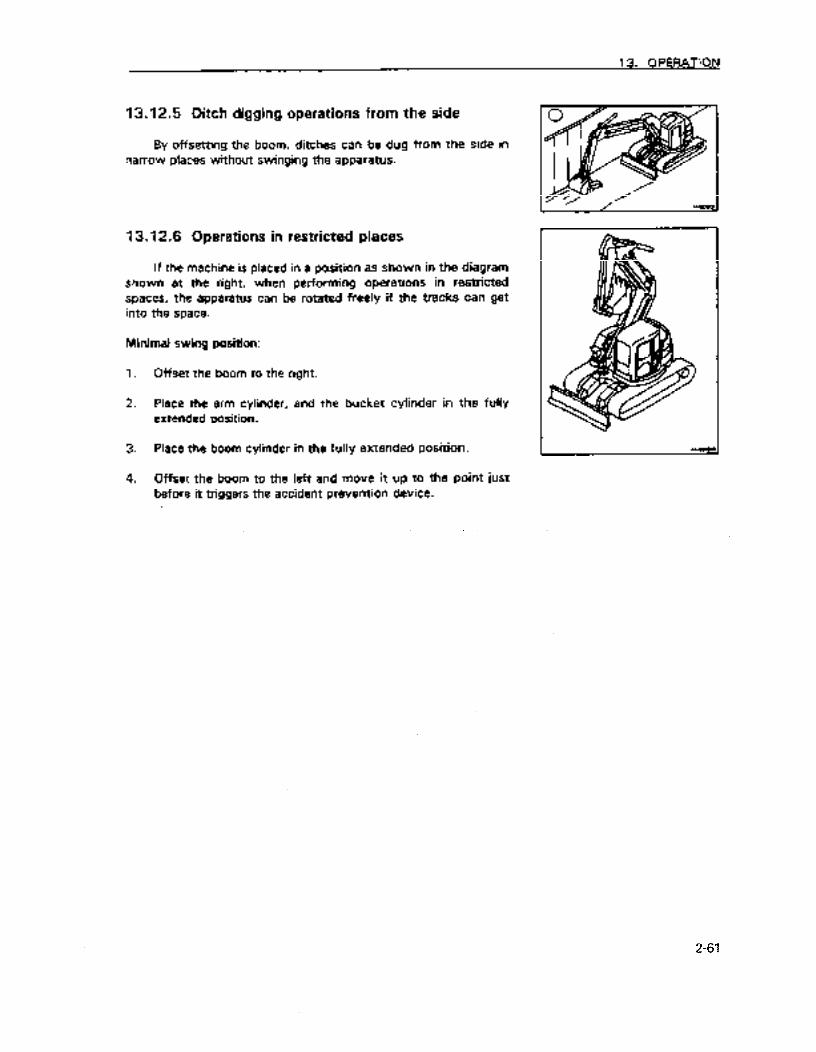
13. OPERATION
13.12.5 Ditch digging operations from the side
By offsetting the boom, ditches can be dug from the side in narrow places without swinging the apparatus.
13. ‘I 2.6 Operations in restricted places
If the machine is placed in a position as shown in the diagram shown at the right, when performing operations in restricted spaces, the apparatus can be rotated freely if the tracks can get into the space.
Minimal swing position:
1. Offset the boom to the right.
2. Place the arm cylinder, and the bucket cylinder in the fully extended position.
3. Piace the boom cylinder in the fully extended position.
4. Offset the boom to the left and move it up to the point just before it triggers the accident prevention device.
2-61
https://tractormanualz.com

13.13 CHANGING THE BUCKET
a Warning!
0 Metal filings will fly when pounding the pins with a hammer and if they get in the eye can cause serious inMy. Use protective clothing like safety goggles, helmets and glove when performing this task.
0 Place the bucket so that it is stable and secure after removing it.
Perform thii operation in a level place with firm footing. When this is done together with other personnel, perform the operation with clear signals and give sufficient heed to safety concerns.
1: Lower the bucket onto level ground.
Additional explanation
When removing the pins place the bucket lightly on the ground. If the weight of the bucket is entirely on the ground they will be more difficult to get out.
2. Remove the stopper boits and nuts, remove pins (A) and (3) and detach the bucket.
NOTICE
Be careful not to get sand and mud on the pins that have been removed. Also be careful not to damage thedust seals that are in both ends of the bushing.
3. Align the arm with hole (11, then align the link with hole (21 and install pins (A) and (B) after you have coated them with grease.
Additional explanation
when attaching the bucket, the 0 rings ares easily damaged SO fit the 0 rings to the position shown in the diagram at the right. When pounding in the pins drop the 0 rings in the proper groove.
4. InstaIl the stopper bolts and nuts for each pin and grease the pins.
2-62
https://tractormanualz.com

13.14 PARKING THE MACHlNE
Avoid sudden stops. Give yourself ample room when stopping.
Q Warning!
Park the machine in a firm, level place. Avoid parking on slopes. When you must park the machine on a slope, block the tracks and imbed the teeth of the bucket in the ground so the vehicle will not move.
a Warning!
Always make sure that the safe&lock lever is in the locked position before standing up from the operator’s seat. If you accidentally touch the lever for moving the machine or rotating the arm and boom apparatus and it is not locked, there may be a sudden movement which may result in serious injury.
7. Place the right and left forward/ reverse travel control levers (1) in the neutral pc~sition.
2. Lower the engine speed to low idling by fuel control dial (2).
3. Put the bottom of the bucket so that it is ievei and parallel to the ground and lower it to the ground.
4. Drop the blade to the ground.
2-63
https://tractormanualz.com

5. Place locking lever (3) in the locked position.
13.15 CHECKS AFTER COMPLETING OPERATION
Check the engine coolant temperature, engine oil pressure and the amount of fuel remaining on the monitors.
13.16 STOPPING THE ENGINE
NOTICE
Do not stop the engine abruptly except when there is an emergency. Stopping the engine abruptly before it has cooled will shorten the life of various engine components. If the engine has overheated do not stop the engine suddenly. Aliow it to run et moderate speed and stop it after it has gradualiy cooled down.
1. Run the engine for 5 minutes at a low idle and allow it to cool down gradually.
2. Turn the key in the ignition switch (1) to the OFF position.
3. Remove the key from the ignition switch ( 1).
Engine coolant E P
2-64
https://tractormanualz.com
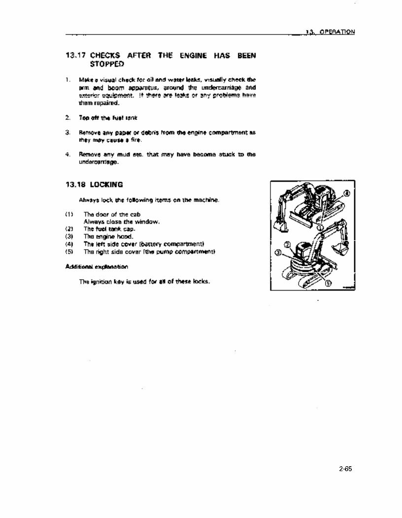
13.17 CHECKS AFTER THE ENGINE HAS BEEN
1.
2.
3.
4.
STOPPED
Make a visual check for oil and water leaks, visually check the arm and boom apparatus, around the undercarriage and exterior equipment. If there are leaks or any problems have them repaired.
Top off the fuel tank
Remove any paper or debris from the engine compartment as they may cause a fire.
Remove any mud etc. that may have become stuck to the undercarriage.
13.18 LOCKING
Always lock the following items on the machine.
(11 The door of the cab Always close the window.
(2) The fuel tank cap. (3) The engine hood. (4) The left side cover (battery compartment) (5) The right side cover (the pump compartment)
Additional explanation
The ignition key is used for all of these locks.
--
2-65
https://tractormanualz.com

53.19 USING THE 4 SYSTEMS
The 4 systems are the bucket-cab, canopy accident prevention device and the automatic control system for the arm and boom apparatus.
Always observe the following precautions so that these devices will operate properly.
A Warning! I
Do not remove sensors, modify their installation or overhaul them as this may lead to faulty operation of the accident prevention devices. Always rely upon Komatsu or your Komatsu distributor for servicing these. If a sensor is hit or is discovered to have exterior damage, check the operation of the automatic stop system. If there is a problem request inspection and repair service from Komatsu or your Komatsu dealer. Do not perform any operations that will immerse the sensors in water. If by some chance the sensors have been immersed check the operation of the automatic stop system. If there is a problem request inspection and repair service from Komatsu or your Komatsu deder. Do not use the automatic stop override switch other than when there is a problem with the four systems and you are moving the machine to a safe place. The 4 systems will not operate normally if you convert from the standard arm and boom apparatus to special attachments. If you are pIarming on using attachments other than those specified by Komatsu pleas consult with Komatsu or your Komatsu distributor.
NO
l
TICE
If there is an abnormali in the 4 systems the controller will perform a self-diagnosis, flash the light on the monitor for the electrical system monitor (1) on the monitor panel, sound a buzzer and display an error code on the depth indicator display (2).
l Depending on what has gone wrong with the 4 systems, though the controller has not performed a self-diagnosis, you may not be able to manipulate the arm and boom apparatus. After moving the machine to a safe location, ask Komatsu or your Komatsu distributor to check the machine.
NOTICE
Before using the 4 systems, always perform the checks required before and after starting the engine.
In cold weather, use the systems after warming up sufficiently. If the hydraulic fluid is cold, the automatic stop positions will be off.
2-66
https://tractormanualz.com

13.19.1 The bucket - cab accident prevention device
When apparatus is offset to the left the arm and boom come back too far and when the apparatus is offset to the right and the offset, arm and boom have been drawn back this device warns that the bucket will hi the cab and automatically stops operation of the boom and arm apparatus.
A Warning!
This is equipment designed to prevent accidents in rare circumstanties and performing operations relying on this device can be dangerous. Always be careful and operate the machine so that the arm and boom does not come near the cab.
n Operation of the accident prevention device
Reduced operating speed areas (forward and reverse directions only).
When performing operations and the arm and boom apparatus approaches the cab and the bucket enters the area A in the diagram at the right, the speed of the arm and boom apparatus will be reduced. This is to prevent the dirt and sand in the bucket from spilling which would occur if the arm and boom apparatus were stopped.
Automatic stop
If the bucket approaches the cab more closely and enters the range B shown in the diagram at the right, the movement of the arm and boom apparatus will automatically stop.
Emergency stop
If for some reason the arm and boom apparatus does not stop automatically when it enters range B, all operations (boom, arm, bucket, swing) will cease when the bucket reaches the area denoted by C in the diagram at the right.
At this time “91” will be displayed on the depth display of the monitor panel and self-diagnosis will be performed. The bucket can be moved forward or to the right and self diagnosis discontinued with the override switch.
However, when this happens have the machine inspected immediately.
2-67
https://tractormanualz.com
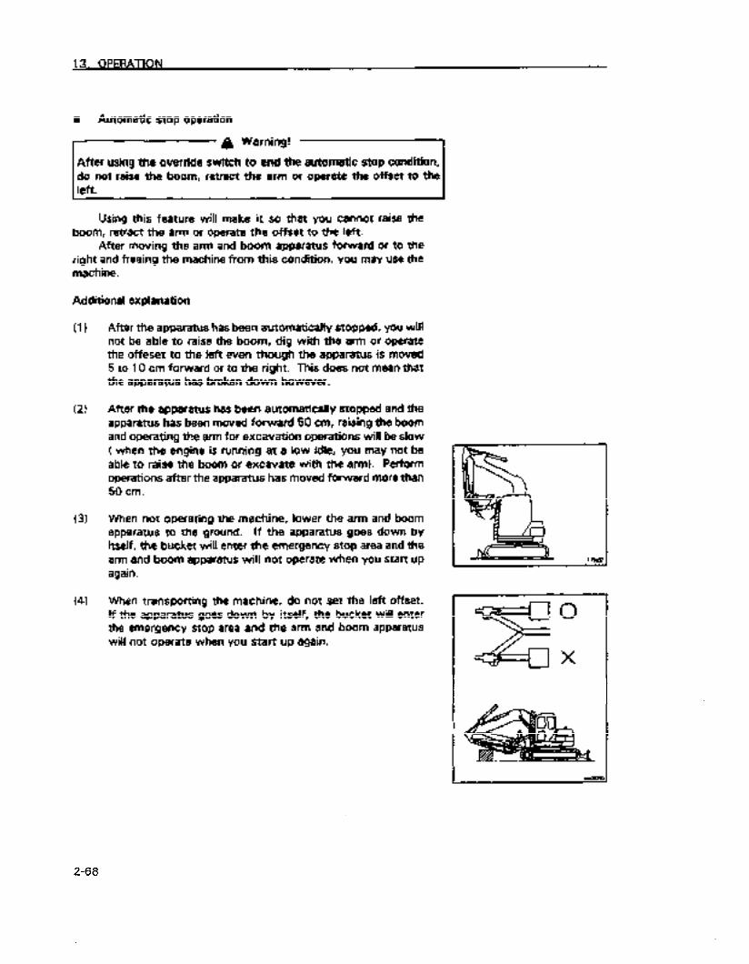
n Automatic stop operation
A Warning!
After using the override switch to end the automatic stop condition do not raise the boom, retract the arm or operate the offset to the left.
Using this feature will make it so that you cannot raise the boom, retract the arm or operate the offset to the left.
After moving the arm and boom apparatus forward or to the right and freeing the machine from this condition, you may use the machine.
Additional explanation
(1)
(2)
(3)
(4)
After the apparatus has been automatically stopped, you will not be able to raise the boom, dig with the arm or operate the offeset to the ieft even though the apparatus is moved 5 to 10 cm forward or to the right. This does not mean that the apparatus has broken down however.
After the apparatus has been automatically stopped and the apparatus has been moved forward 50 cm, raising the boom and operating the arm for excavation operations will be slow ( when the engine is running at a low idle, you may not be able to raise the boom or excavate with the arm). Perform operations after the apparatus has moved forward more than 50 cm.
When not operating the machine, lower the arm and boom apparatus to the ground. If the apparatus goes down by itself, the bucket will enter the emergency stop area and the arm and boom apparatus will not operate when you start up again.
When transporting the machine, do not set the left offset. If the apparatus goes down by itself, the bucket will enter the emergency stop area and the arm and boom apparatus will not operate when you start up again.
2-68
https://tractormanualz.com

13.19.2 Using the automatic control device
Depth display Displays the depth from the sutface of the ground
Depth display 0 set mode Displays the depth from a standard surface
Depth mode
Height mode
Offset mode
Designates the depth to which the boom will go.
Designates the height to which the boom will go.
Determines the position of the left offset for ditch excavation etc.
Both the depth display and the depth display 0 set mode explained above may be designated together with the other 3 modes. Make the settings which are suitable for the task at hand.
2-69
. . . . . https://tractormanualz.com
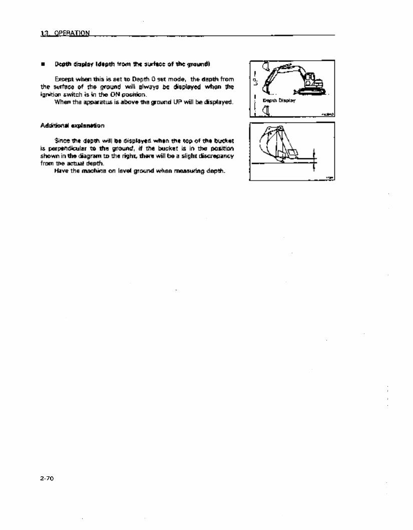
13. OPERATION
n Depth display (depth from the surface of the ground1
Except when this is set to Depth 0 set mode, the depth from the surface of the ground wifl always be displayed when the ignition switch is in the ON position.
When the apparatus is above the ground UP will be displayed.
Additional explanation
Since the depth will be displayed when the top of the bucket is perpendicular to the ground, if the bucket is in the position shown in the diagram to the right, there will be a slight discrepancy from the actual depth.
Have the machine on level ground when measuring depth.
I Depth Display
. l . & \
2-70
https://tractormanualz.com

8 Setting Depth 0 set mode
Will display the depth of a standard surface that has been arbitrarily chosen as 0 and will display the depth from that surface.
1. Set the mode selection swich (11 to the depth 0 set mode postion.
2. Have the machine on level ground, align the bucket with where you want to have the standard surface. The way the bucket is placed at the time you align it with the surface will be the standard for displaying depth.
3. Place the setting switch in the SET position. The display will show a depth of 0.0 m.
4. Move the bucket to the place depth (the measuring surface).
where you want to measure
5. When resetting so that depth from the ground surface will be displayed, set the mode selection switch (1) to the depth 0 set mode position and turn the set switch (2) to CLEAR. Depth will be displayed from the surface of the ground.
Additional explanation
l Place the bucket in the same position at the place you wish to measure the depth as you did when the bucket was aligned with the standard surface.
l If you turn the ignition switch to OFF without changing the mode setting, the mode setting wili be cancelled.
2-71
https://tractormanualz.com

8 Setting Depth mode
If you lower the bucket to the depth arbitrarily set, movement of the boom any lower or any pulling movement of the arm will automatically cease.
1. Place the mode selection switch (‘1) in the depth mode position.
2. Lower the boom to the designated position.
3. Place set switch (2) in the SET position. A buzzer will sound twice and the light of indicator (3) will come on.
4. If you raise the bucket and then lower it, it will stop at the designated depth.
Additional explanation
The location where the bucket will stop will vary slightly with the following conditions.
(1) When lowering the boom slowly, the bucket will stop moving will stop before it gets to the designated position
(2) In cold weather the bucket will sometimes stop moving after it has gone past the designated position so the machine should be sufficiently warmed up and the hydraulic fluid warmed. See item 13.3 ” Things to be done and checked after starting the engine” for details about warming up the engine.
NOTICE
When the depth has been measured when the arm is pulled in and in the position seen in the diagram on the right, be careful because the bucket will go to a greater depth when the arm is moved forward.
NOTICE
Be careful not to damage buried objects because when the depth is measured when the bucket is pushed forward as shown in the diagram on the right, it will go deeper when pulled in.
2-72
https://tractormanualz.com

5. To clear the depth mode, place the mode selection switch (1 I to the depth mode position and the setting switch (21 to CLEAR. The light on indicator (3) will go out.
Additional explanation
Even though you may have set a mode, if you turn the ignition switch to the OFF position the mode setting will be cleared.
2-73
https://tractormanualz.com

l Setting height mode
If you raise the boom to apparatus will automaticall stop.
the height arbitrarily set, the
1. Place the mode selection switch (I) in the height mode position.
2. Raise the boom to the designated position.
3. Place set switch (2) in the SET position. A buzzer will sound twice and the light of indicator (3) will come on.
4. If you lower the boom and ?hen raise it, it wi!! stop at the designated height.
NOTICE
In height mode the height the boom will rise to is set. If the height is set when the arm and bucket are retracted as shown in the diagram to the right, the height of the apparatus may be greater when the arm and bucket are extended forward. Be careful not to make undesired contact with objects surrounding the machine.
5. To clear the height mode, place the mode selection switch (1) to the depth mode position and the setting switch 12) to CLEAR. The light on indicator (3) will go out.
Additional explanation
Even though you may have set a mode, if you turn the ignition switch to the OFF position the mode setting will be cleared.
2-74
Depth diplay I
https://tractormanualz.com
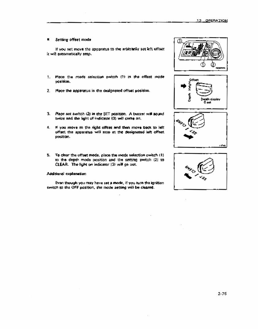
13. OPERATION
m Setting offset mode
If you set move the apparatus to the arbitrarily set left offset it will automatically stop.
1. Place the mode selection switch (1) in the offset mode position.
2. Place the apparatus in the designated offset position.
3. Place set switch (2) in the SET position. A buzzer will sound twice and the light of indicator (3) will come on.
4. If you move to the right offset and then move back to left offset the apparatus wil! stop at the designated left offset position.
5. To dear the offset mode, place the mode selection switch (1) to the depth mode position and the setting switch (2) to CLEAR. The light on indicator (3) will go out.
Additional expianatfon
Even though you may have set a mode, if you turn the ignition switch to the OFF position, the mode setting will be cleared.
2-75
https://tractormanualz.com

13. OPERATION
13.20 USING ROAD LINER (FOR MACHINES SPECIFIED FOR USE WITH ROAD LINER)
1320.1 How to use road liner properly
The road liner have some qualities superior to steel track shoes but if they are used in the same way ai steel track shoes these qualities cannot be fully reafized. Proceed with a task in a way that conforms to the area to be worked in and the demands of the task itself.
A Comparison of Road liner and Steel track shoes
I Road Steal track liner shoes
Low vibration 8 A
Run smoothly ho squeaking) 0 0
Low noise Q A
Do not damage paved surfaces 0 A
Easy to handle 0 A
Easily damaged 0 0
Good towing strength 0 0
0 : Especially good
0:Gccid
A: Average
The obverse side of the fact that - road liners have many advantages due to the special performance of these materials is that they are not as resiiient. Consequently, if you are sufficiently cognizant of the peculiarities of road liners do not use them in operations not recommended and follow precautions in handling ,them, you can prolong the Iii of road liners and make use of the advantages that road liners Oh.
Before using them please refer to item 13.19.3 ‘Precautions in using road liners”.
13.20.2 Concerning the warranty on Road liner
The warranty does not apply if damage occurs due to the fault of the customer by failing to service and inspect and maintain proper track tension or failing to observe precautions in use of by performing prohibited operations such as operating on sharp surfaces such as “steel pitings, lJ shaped ditches, on sharp angles like blocks, on the edges of cut stone or rocks, steel rods, and other objects that may cut the track shoes.”
2-76
https://tractormanualz.com

13. OPERATION
1320.3 Precautions in using road liner
Prohibited operations
Do not perform the foilowing operations
If the machine is operated or swung, on crushed stones, ex- tremely uneven and hard rockbed, steel bars, steel scraps or near
‘. edges of steel plates, road .liners may be damaged.
If the machine is operated on a riverbed, etc. where there are many boulders of various sizes, tie boulders may be caught in the road liners to damage or remove the latter. If the road lipers,$p when the machine is used for dozing, their lives are shortened.
Take care that oil, fuel, chemical soivents, etc. does not make prolonge contact to the road liners. If any adheres, wipe it off immediately. Do not drive the machine on a road where there are pools of oil, etc.
‘When leaving the machine unused for a long_period (more than three months), store it in place where it will not be exposed to direct sunlight and rain.
Do not drive the machine on a hot place such as a fire, a steei plate left under the direct sunlight, hot asphalt, etc.
If either track is raised with the work equipment and the other track is operated, may be damaged. - ..--
When the rubber parts of the road liner are so worn or broken that the head of the mounting bolts are scratched, replace the shoe immediately. If the bolt heads are broken, the bolt cannot be removed.
When using the road liners, be sure to instail them to the al links on both sides. tf they are installed to only a part of the links, their durability is greatly lowered.
2-77
https://tractormanualz.com

13. OPERATION
13.20.4 Precautions in use
Observe the following precautions when using.
Avoid swinging on concrete road surfaces.
Avoid making sudden changes of direction when traveling as this causes wear and damage to the rubber track shoes.
Avoid turning in a place where there is a large level difference. Ride over .a level difference at right angles.
When the arm and boom apparatus has been used to raise the machine, lower it gently.
When the material to be handled is something that is oily when crushed (like beans, corn, or the sediment from making vegetable oil, do not use the vehicle or if used, wash it Off
with water following the opera&m.
When the material to be handled is salt, ammonium S~lphate, potassium chloride, or double superphosphate there wiil be substantial corrosion of parts so do not use the vehicIe or if used wash it off with wster follow the operations.
Do not use for operations on the seacoast as there will be substantial corrosion of parts due to the salt.
When handling salt, sugar, wheat or beans etc. and there are deep tears in the road liners:, there is the danger that these things will get into lugs etc. through the tears in the rubber so repair these tears before carrying out the operation.
Do not operate the machine by pressing it against a concrete bank, wall, etc.
The road liners slip easily on wet steel plate or on roads covered with snow or ice. When driving br working on a slope, take care to prevent slipping.
2-78
:.-. . . . https://tractormanualz.com

13. OPERATION
l Use road liners in the temperature range from -25°C to +65”C.
l Take care not to damage road liners with the bucket during operation.
1. Avoid rotating the amt and boom appafatua when there are large diierences in grade like on curbs or crags (more than 20 cm). When traveling ovec differences in grade, approach them at 90° angles.
2. When climbing a slope in reverse and at the point where level ground meets the slope, do not rotate the arm and boom apparatus while climbing. When climbing a slope and you must rotate the boom do so slowly.
3. Do not travel with one track raised on a slope (with the machine ‘mdined at loo or morel and the other track on level ground. Travel with both tracks on the-same surface so that you will not damage the road liners.
2-79
https://tractormanualz.com

Observe the pertinent regulations when transporting the vehicle and do so safely.
, 14.1 HOW TO LOAD AND UNLOAD THE VEHICLE
A Warning!
Be particularly carefu when loading and unloading the vehicle as this can be dangerous. Load and unload the vehide after reducing the engine speed and move the vehide slowly at low travel speed. Select a firm, level place for loading and make sure that it is a sufficient distance from the shoulder of the road. Use ramps that are of adequate strength and make sure that they are sufficiently wide, long and thick for safe loading and unloading. If the ramps are likely to bend significantly. reinforce them with blocks. Remove oil residues and foreign matter that may be stuck to the ramps so that the machine will not slide. Remove mud from around the tracks. Never correct the position of the tracks on the ramp while on the ramp. lf you need to correct the position of the tracks, back off of the ramp, correct the position of the tracks and the remount the ramp.
0 If you are going to rotate the boom while on the trailer, do so with caution as the machine’s footing is unstable.
A Caution! ._I
0 Always make sure that the sliding door on vehicles that come with a cab is locked whether the door is open or closed.
l Always open or dose the door when you are on level ground. l The strength needed to open or dose the door on a slope or on
a ramp may vary suddenly so avoid trying to open or dose it on an incline.
Always use ramps or a loading platform for loading and unloading and do so as follows:
1. Make sure that the trailer’s brake is engaged. Block the wheels so that they cannot move. Fix the ramps in place and make sure that they are set so that the center of the machine and the trailer are aligned. Make sure that both the right and left ramps are of the same height.
Use the ramps so that the angle of incline is less than 15O.
Set the distance between the ramps so that the center of each track will be on the center of its ramp.
2-80
https://tractormanualz.com

14. TRANSPORTING
2. Lower the engine speed using the fuel control dial.
3. Align the machine with the ramps and proceed slowly. Load and unload the machine with the arm and boom apparatus in as low a position as possible so that it does not hit the trailer. Do nor use the accelerator pedal.
Do not use any other control !evers other ?han the forward/ reverse travel controf lever.
4. Load the machine into the designated position on the trailer.
When the arm and boom apparatus is attached load the front end on first. When there is no arm and boom apparatus load the rear end fist.
i4.2 PRECAUTIONS WHEN CARRYING THINGS
After placing the machine in the designated position on the traiier, secure it as foilows.
1. Lower the blade.
2. Fully extend the bucket and arm cylinders and then slowly lower the boom.
3. Stop the engine and remove the key from the ignition switch.
NOTICE
To prevent damage to the bucket cylind& during transport of tk vehicfe, Place a wedge under either end of the bucket cylinder so that it will not touch the bed of the trailer.
4. Lock each control lever with the locking lever.
5. To ensure that the machine will not move during transport, pJace wedges in front of and behind the tracks and secure the vehicle with chains or wire rope. Secure it firmly so.that it will not slip to the side in particular.
2-81
https://tractormanualz.com
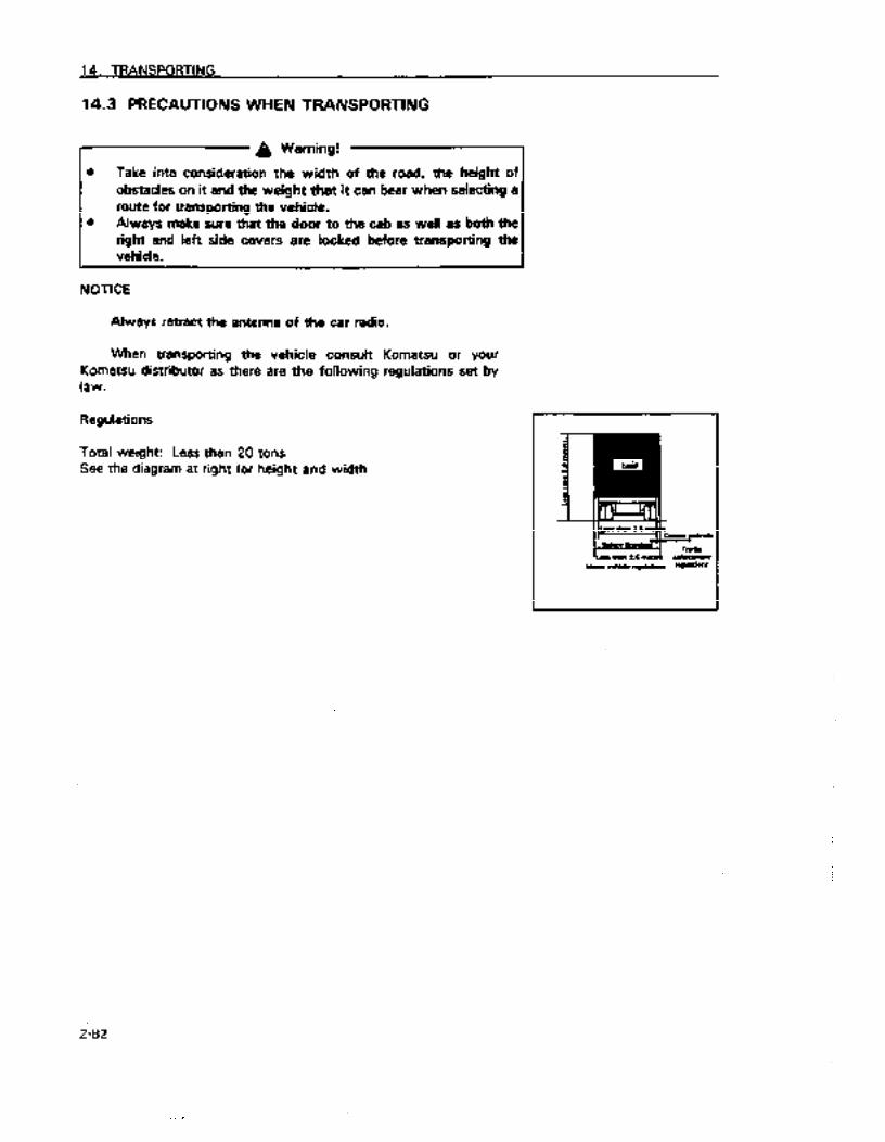
14. TRANSPORTING
14.3 PRECAUTIONS WHEN TRANSPORTING
I A Warning!
l Take into consideration the width of the road, the height of obstacles on it and the weight that it can bear when selecting a route for transporting the vehicle.
0 Always make sure that the door to the cab as well as both the right 8nd left side covers are locked before transporting the vehicle.
NOTICE
Always retract the antenna of the car radio.
When transporting the vehicle consult Komatsu or your KOiTI8tsU distributor as there are the following regulations set by law.
Regulations
Total weight: Less than 20 tons See the diagram at right for height and width
2:8i
https://tractormanualz.com

14. TRANSPORTfNG
14.4 METHOD OF UFTlNG MACHINE
A WARNING
Never raise the machine with any worker on it.
Always make sure that the wire rope used for lifting the machine is of ample strength for the weight of the machine.
Never try to lift the machine in any posture other than the posture given in the procedure below. There is danger that the machine may lose its balance.
The machine must never be raised with the undercarriage turned.
Never Iii the machine with the undertirriage at an angle. Swing the work equipment to the sprocket end and set the upper structure and undercarriage parallel before starting lifting operations.
When lifting the machine, be careful of the position of the center of gravity and &ways maintain the balance.
It is dangerous to go under the machine. when it is raised. Never go under the machine in such cases.
.
NOTICE l Details of load + See 9% SPECIPlCAllONS”. l The spacified value is for the standard specification. The lifting
dimensions vary according to the attachment or option actually installed. In such cases, please contact your Komatsu distribu- tor.
14.4.1 STANDARD SPECIFICATION MACHINE When lifting the machine, select a flat place and do as follows.
For machines with a blade, raise the blade.
1. Start the engine, then swing the work equipgent so that the work equipment is at the rear of the machine (sprocket end).
2. Extend the bucket cylinder and arm cylinder fully, then lower the work equipment to the ground with the boom cylinder as shown in the diagram on the right.
3. Stop the engine, check that there is nothing around the opera- tor’s compartment, then get off the machine. Lock the door and front glass of the cab securely.
I Sprocket .E3C9,0.
2-83
https://tractormanualz.com

14. TRANSPORTING
4. Pass wire ropes between the 1st and 2nd track rollers from the [- front and between the 1st and 2nd track rollers from the rear.
5. Make the lifting angle of the wire rope 30 - 40”, then raise the machine slowly.
6. When the machine comes off the ground, stop and allow the machine to stabilize, then raise it slowiy. _.
I
Part wire roiee between the 1st and .Znd track robs from the. front and the rear.
2-84
https://tractormanualz.com
‘l5. HANDLING IN COLD WEATHER
15.1 PREPARATION FOR LOW TEMPERATURES
When temperatures drop, starting becomes more difficult and coolant freezes etc. so the following should be done.
15.1.1 Fuel and lubrication
Change to fuel and oil with low viscosity for all components. See item 21 “Use of fuel and lubricants according to ambient temperatures” for specific viscosities.
l Coolant
A Warning!
Coolant is flammable so keep flames away from it. Do not smoke when handling coolant.
NOTICE l Never use methanol, ethanol or propanol based antifreeze.
l Absolutely avoid using any water leak preventing agent irre- spective of whether it is used independently or mixed with an antifreeze.
l Do not mix one antifreeze with a diierent brand.
For details of the antifreeze mixture when changing the coolant, see “25.2 Non-scheduled maintenance”.
Use a Permanent Antifreeze (ethylene glycol mixed with corro- sion inhibitor, antifoam agent, etc.) meeting the standard require- ments as shown below. With permanent antifreeze, no change of coolant is required for a year. If it is doubtful that an available antifreeze meets the standard requirements, ask the supplier of that antifreeze for information. Standard requirements for permanent antifreeze l SAE . . . . . . . . . . . . . . . . . . . . . . . . . . . . . . . . . . . . . . . . . . . . . . . . . . . . . . . . . . . . . . . . . . . . . . . . . . . . . . . . . . . . . . . . . J1034 l FEDERAL STANDARD . . . . . . . . . . . . . . . . . . . . . . . . . . . . . . . . . . . . . . . . . . . . .._.... O-A-5480
Additional explanation Where no permanent antifreeze is available, an ethylene glycol
antifreeze without corrosion inhibitor may be used only for the cold season. In this case, clean the cooling system twice a year (in spring and autumn). When refilling the cooling system, add antifreeze in autumn, but do not add any in spring.
2-85
https://tractormanualz.com

15. HANDLING IN COLD WEATHER
n Battery
7 4 Warning! -I
0 Because batteries emit flammable gases, do not bring open flames close to them.
0 Battery fluid is hazardous. Se careful so that it does not get in your eyes or on the skin. If it does, flush them with water and consult a .physician.
When temperatures drop battery capacity drops. If the charge is low there is the danger that the battery fluid may freeze. Maintain the battery charge as close as possible to 100 per cent and be careful to maintain temperature to prepare for starting the following morning.
Additional explanation
Measure the specific gravity and calculate the rate of charge from the following table
Temperature of fluid f ’ Cl
0 I -10
1.29 1.30 1.31
1.27 1.28 1.29
1.25 1.26 1.27
1.24 1.25 1.26
-20
15.2 PRECAUTIONS AFTER COMPLETING OPERATIONS
In order to prevent things like mud and water and the undercarriage from freezing which make it impossible to move the machine the following morning, observe the following precautions.
0 Remove mud and water etc. adhering to the machine. In particular try to prevent drops of water on the surface of the hydraulic cylinders and mud getting into the seals and damaging them.
0 Park the vehicle on firm dry ground. If such a place is not available, put plywood planks down on the ground and park on them. This will prevent the ground surface and the undercarriage from freezing and the machine will be able to be moved the next morning.
2-86
https://tractormanualz.com

15. HANDLING IN COLD WEATHER
l Open the drain cock and drain water accumulated in the fuel system to prevent it from freezing.
l Functioning of the battery drops markedly in cold temperatures To maintain its temperature it should be covered or removed from the machine and placed in a warm place so that it can be re-iiistalled the next morning. When the battery fluid level is low, fill the battery with dhtiiled water the next morning prior to starting work. To prevent water in the battery from freezing do not add water at the end of the day after work is finished.
15.3 PREPARING THE CAR HEATER
Use the car heater when the temperatures get low. To use the car heater, turn valve (1) which is attached to the
water manifold to the left to open it. When not using the car heater for long periods turn the valve
(1Itotherightandcloseit.
15.4 AFTER THE COLD WEATHER SEASON IS QVEW
After the seasons change and temperatures get warmer, do the following.
l Change the oil and fuel of each component to the oil and fuel with recommended viscosity specified in item 21 “Use of fuel, cootant and lubricants according to ambient tempef’ature.”
l If you have had to use AFPT anti-freeze (winter one season type). drain all of the anti-freeze from the cooling system, flush the system with water and fill with fresh water.
2-87
https://tractormanualz.com

16. LONG-TERM STORAGE
16.1 PEFORE STORING THE MACHINE
NOTICE
Place the machine in the position shown in the diagram on the right to protect the cylinder rods when the machine is not being used. (Prevents the cylinder rods from rusting.1
Store the machine in the following manner when not using for a long time.
Store inside a building after washing and cleaning each part. If the machine must be left outside, put it in on level ground and cover it. Fill the fuel tank, grease the machine and change the oil. Cover the exposed portions of the piston rods of the hydraulic cylinders with grease. Disconnect the negative terminal of the battery and either cover the battery or remove it from the vehicle and store it elsewhere. Add anti-freeze to the coolant solution if the temperature will go below freezing. Normally Komatsu’s special Supercoolant (AF-ACL) has been added to the coolant water and need not be changed as it is effective to -1 OOC. When the temperature is expected to go below -1OOC see item 25.2 “Non-scheduled maintenance” and adjust the concentration accordingly. Lock each control lever and pedal with the locking lever and pedal locks. Place the stop valve on vehicles that can be fitted with attachments to the “locked” position. Install blind plugs in the elbows. Set the selector valve on vehicles that can be fiied with attachments to the “crusher and general attachments” position.
2-88
https://tractormanualz.com

16. LONG-TERM STORAGE
16.2 DURING STORAGE
A Warning!
When it is necessary to run the machine indoors to prevent the I
machine from rusting, open the windows and doors to improve ventilation to prevent poisoning from exhaust gases. J
While the machine is not being used, run the machine once a month, and ensure that parts that need lubrication are lubricated. Charge the battery at the same time. Also run the car cooler (if equipped).
16.3 AFTER STORAGE
NOTICE
Consult with Komatsu or your Komatsu distributor if you intend to use the vehicle and have not run the machine once a month to prevent rusting.
When you intend to use the machine af&er long term storage, do so by handling the machine as follows.
0 Wipe the grease off the hydraulic cylinder rods.
l Fill with oil and grease everything.
l Do not use triclene when washing the fuel tanks since the fuel tanks are plastic. Using triclene will weaken the fuel tanks.
2-89
https://tractormanualz.com

17. TROUBLESHOOTING
17.1 PHENOMENA THAT ARE NOT BREAKDOWNS
1)
2)
3)
4)
m
1)
2)
3)
The following phenomena are not breakdowns:
When the arm is pulled in, the arm will move slightly more slowly when it reaches a nearly vertical position.
The speed will drop momentarily when the teeth of the bucket are nearly horizontal.
Sounds will be emitted from the brake valves when the apparatus begins or finishes swinging.
Sounds will be emitted from the travel motor when descending a steep slope at low speed.
Phenomena that are not breakdowns of the 4 systems
Not being able to raise the boom, move the arm or offset to the left even though the apparatus has been moved from 5 to 10 cm forward or to the right after it has been automatically stopped.
Operating speed of the arm and boom apparatus being slow, after moving it forward about 50 cm after it has automatically stopped, even though the boom can be raised and the arm can be used for excavation. (You may not be able to raise the boom or move the arm for excavation when the engine is running at a low idle.)
When the apparatus stops automatically in the midst of returning to the original position after moving forward after it has automatically stopped in a left offset operation. (If the apparatus is offset 5 cm to the right, you can return to the original position. i
2-90
<.-, . . . . ., https://tractormanualz.com

17. TROUBLESHOOTING
4) When the apparatus cannot be manipulated or be swung or operated in any way after the override switch has been activated when the controller makes a self-diagnosis when the apparatus moves toward the cab after it has been automatically stopped. (error code “91 n is displayed)
5) When the position where the apparatus automatically stops is off when the apparatus angle sensor has been removed and re-installed.
6) When the teeth of the bucket are lowered to the ground and the depth displayed is not 0.0 m.
7) When the depth indicated by the position of the bucket is off.
8) When depth mode is set and the boom stops before it gets to the designated place (particularly when moving the boom slowly).
Fl73lb
9) When the position where the apparatus stops is off when the accident prevention device and the automatic control device are activated in cold weather. (When the hydraulic fluid warms up, it will return to normal.)
2-91
https://tractormanualz.com
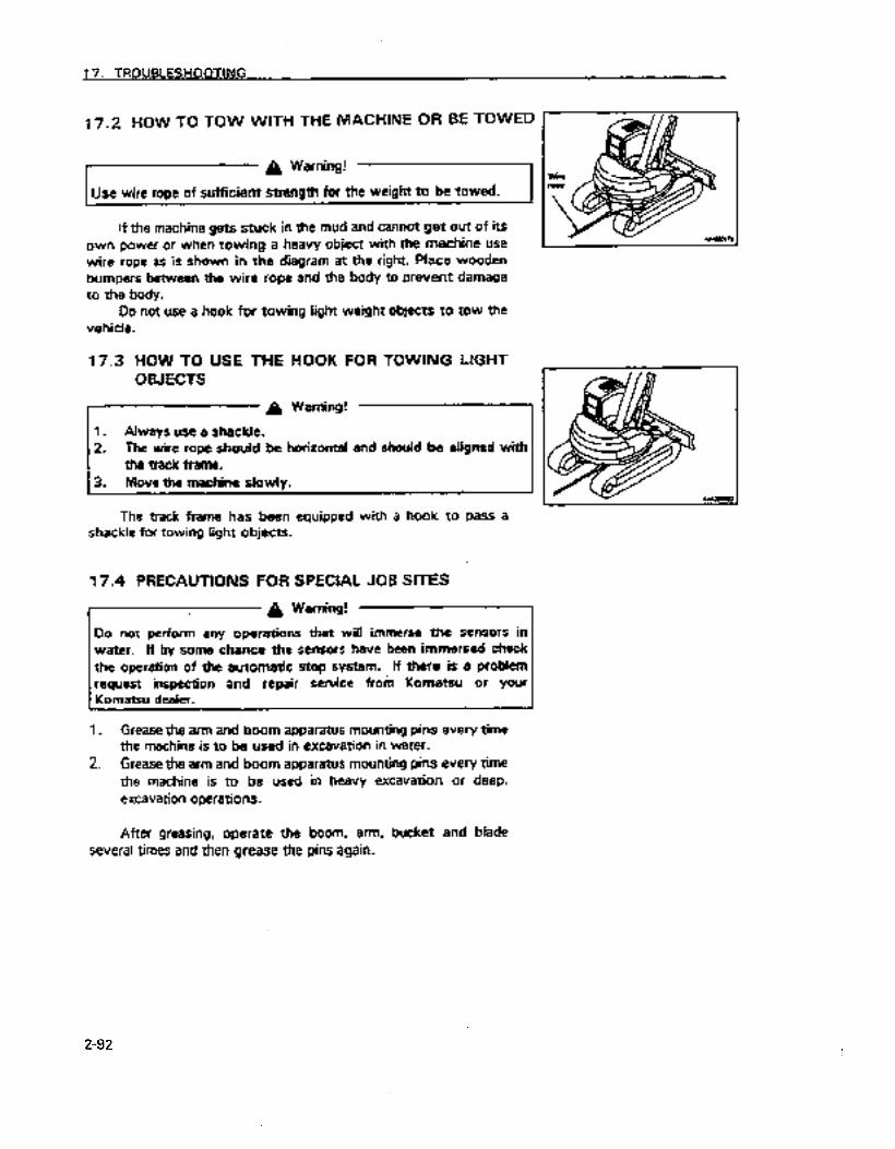
17.2 HOW TO TOW WITH THE MACHINE OR BE TOWED
a Warning!
Use wire rope of sufficient strength for the weight to be towed. 4
If the machine gets stuck in the mud and cannot get out of its own power or when towing a heavy object with the Machine use wire rope as is shown in the diagram at the right. Place wooden
bumpers between the wire rope and the body to prevent damage to the body.
Do not use a hook for towing light weight objects to tow the vehicle.
17.3 HOW TO USE THE 0 WECTS
HOOK FOR TOWING LIGHT
The track frame has been equipped with a hook to Pass a shackle for towing light objects.
17.4 PRECAUTIONS FOR SPECIAL JOB SITES
I A Warning! ‘~1
Do not perform any operations that will immerse the sensors in water. If by some chance the sensors have been immersed check
the operation of the automatic stop system. If there is a problem request inspection and repair service from Komatsu or your Komatsu dealer.
1. Grease the arm and boom apparatus mounting pins every time the machine is to be used in excavation in water.
2. Grease the arm and boom apparatus mounting pins every time the machine is to be used in heavy excavation or deep. excavation operations.
After greasing, operate the boom, arm, bucket and blade several times and then grease the pins again.
2-92
https://tractormanualz.com
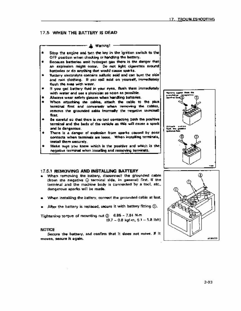
17. TROUBLESHOOTING
17.5 WHEN THE BA-ITERY IS DEAD
7 A Warning!
l Stop the engine and turn the key in the ignition switch to the OFF position when checking or handling the battery.
0 Because batteries emit hydrogen gas there is the danger that an explosion might occur. Do not light cigarettes around batteries or do anything that would cause sparks.
l Battery eiectroiyte contains sulfuric acid and can bum the skin and ruin dothing. If you spill acid on yourself, immediately flush the area with water.
0 If you get battery fluid in your eyes, flush them immediately with water and see a physician as soon as possible.
l Always wear safety glasses when handling batteries. l When attaching the cables, attach the cable to the plus
terminal first and conversely when removing the cables, remove the. grounded cable (normally the negative terminal) first.
0 Be careful so that there is no tool contacting both the positive terminal and the body of the vehicle as this will cause a spark and is dangerous.
Attach cables
0 There is a danger of explosion from sparks caused by poor contacts when terminals are loose. When installing terminals, install them securely.
l Make sure you know ‘which is the positive and which is the negative terminal when installing and removing terminals.
17.51 REMOVING AND &TALUNG BAlTERY l When removing the battery, disconnect the grounded cable
(from the negative @ terminal side, in general) first. If the terminal and the machine body is connected by a tool, etc., dangerous sparks will be made.
l When installing the battery, connect the grounded cable at last.
l After the battery is replaced, secure it with battery fitting 0.
Tightening torque of mounting nut @ 6.86 - 7.84 N-m (0.7 - 0.8 kgf-m, 5.1 - 5.8 Ibft)
NOTICE Secure the battery, and confirm that it does not move. If it
moves, secure it again.
2-93
https://tractormanualz.com

17. TROUBLESHOOTING
17.5.2 Starting the engine using booster cables
Observe the following procedure when starting the engine using booster cables
8 Precautions in connecting and removing booster cables
g, Warning! -1
Never connect the positive terminal to the negative terminal when attaching cables Wear safety glasses when using booster cables to start the engine. When using another vehicle to start the engine make sure that the other vehicle does not touch your vehicle. Because batteries emit hydrogen gas there is the danger that an explosion might occur if sparks are generated near the battery. Do not make mistakes in connecting the booster cables. Never, ever connect a positive terminal with a negative terminal_ The final connection should be to the frame of the rota&g arm and boom. Make sure that this is as far from the battery as possible as this will cause a spark. (However, do not connect the cable to the arm and boom apparatus as conductivity is poor) When disconnecting booster cables, do not allow the respective dips of the two cables to contact each other or to contact the body of the machine.
NOTICE
l Use cables and dips of a size suitable for fhe battery. 0 The battery of the assisting vehicle should be of the same
capacity as that of the vehicle to be started. l Check to see whether there is any damage or corrosion on the
cable and clips. 0 Fasten the clips securely so there is a good connection.
2-94
https://tractormanualz.com

17. TROUBLESHOOTING
a Connecting the booster cables
Put the ignition switch in the OFF position and connect the booster cables in accordance with the order of the numbers in the diagram.
1.
2.
3.
4.
5.
m
1.
2.
3.
Place the ignition switches of both vehicles in the OFF position.
Connect the clip of booster cable (A) to the positive terminal of the battery of the vehicle with a dead battery.
Connect the clip at the other end of booster cable (A) to the positive terminal of the battery of the assisting vehicle.
Connect the clip of booster (B) to the negative terminal of the battery of the assisting vehicle.
Connect the clip at the other end of booster cable (B? to the engine block of the vehicle with a dead battery.
Starting the engine
Check to make sure that the clips of the booster cables are securely fastened to the battery terminals
Start the engine of the assisting vehicle and run it at full throttle.
Turn the ignition switch of the vehicle with a dead battery to the START position and start the engine.
See item 13.2 “Starting engine”
2-95
https://tractormanualz.com
17. TROUBLESHOOTING
1.
2.
3.
4.
l Disconnect@g booster cables
After the engine has started disconnect the booster cables in the reverse order that they were connected.
Remove the clip of booster cable (B) that was connected to the engine block of the vehicle that had a dead battery. Remove the clip at the other end of booster cable (B) *Aat was .- connected to -the negative terminal of the battery of the assisting vehicle.
Remove the clip of booster cable (A) that was connected to the positive terminal of the battery of the assisting vehicle.
Remove the clip at the other end of booster cable (Al that was connected to the positive terminal of the battery of the vehicle that had a dead battery.
2-96
https://tractormanualz.com

17.6 WHEN THIS PHENOMENON OCCURS
17.6.1 Electrical system
l Always contact Komatsu or your Komatsu Dism%utor for remedies that are in parentheses. l For other problems or for problems which you think have causes other than those listed below,
contact Komarsu or your Komatsu distributor for service.
Problem phenomenon
Monitor light is dim even when engine runs at maximum RPM
Light Rickers while engine is running
The charge level monitor Gght stays lii even when the engine is running.
Abnormal noise from the alternator
Starter does not turn over when the ignition switch is turned to start
Pinion of starter motor repeatedly goes in and out (noisily1
Starter motor turns over engine slowlv
Starter motor disengages before engine starts running
Preheat monitor light does not come an.
Oil pressure monitor Gght does not come on when the engine is stopped (when the ignition key is in the ON positiont
When the exterior of the electric heater is not warm when touched with the hand ~
Chief cause
l Defective wiring
l Fan belt tension not properly adjusted
l Defective alternator e Defective wiring
0 Defective alternator
0 Defective wiring l InsuHicient battery charge
l Insufficient battery charge
l Insufficient battery charge l Defective starter
0 Defective wiring l Insufficient battery charge
0 Defective wiring l Defective monitor light
l Defective monitor light l Defective oil pressure
switch
8 Defective wiring a Disconnected wire in
electric heater B Defective operation of
heater relay switch
Remedy
(e check for loose terminals, repair disconnected wires)
l Please conntact your Komatsu distoributor :
(m Replace) ! P Inspect, repair)
/ ii Replace)
i (0 Inspect repair) ~ 0 Charge
l Charge
l Charge to Replace)
(e Inspect, repair1 l Charge
(0 Inspect, repair) (e Replace)
(0 Replace) ( l Replace)
(e Inspect, repair) P Replace)
(0 Replace)
2-97
. ..’ https://tractormanualz.com

17.6.2 General problems with the machine
l Always contact Komatsu or your Komatsu Distributor for remedies that are in parentheses. 0 For other problems or for problems which you think have causes other than those listed below,
contact Komatsu or your Komatsu distributor for service.
Problem phenomenon Chief cause
Travel speed, swing speed, speed of the boom, arm and bucket are slow
Abnormal sound coming from pump
Temperature of hydraulic fluid gets too hot
Tracks come off
Abnormal wear on the sprocket
Bucket rises slowly or does not rise at all l
Remedy
l insufficient hydraulic fluid l Add oil to the specified level, see checks before beginning operations
s Clogged strainer element in I a See 2000 hour service,
hydraulic fluid tank dean
l Loose fan belt
l Dirty oil cooler 0 Insufficient hydraulic fluid
l Tracks are too loose
s ’ Please conntad your Komatsu distoributor
l See 500 hour service, clean l Add oil to the specified
level, see checks before beginning operations
l See maintenance that is not regularly scheduled, adjust tension
l Insufficient hydraulic fluid l Add oil to the specified level, see checks before begiining opemtibns
2-98
https://tractormanualz.com

17. TROUBLESHOOTING
17.6.3 Engine
l Always contact Komatsu or your Komatsu Distributor for remedies that are in parentheses.
l For other problems or for problems which you think have causes other than those iisted below, contact Komatsu or your Komatsu distributor for service.
Problem phenomenon
Engine oil pressure monitor light comes on
Steam escaping from the upper portion of the radiator (the pressure valve)
The radiator coolant temperature gauge red fight comes on.
Though the engine has been operated for a long time, the white light of the engine coofant temperature gauge is on.
The engine will not start when me starting motor is cranked.
Chief cause
s Insufficient ail in the oil pan (taking in air)
a Oil filter cartrfdge is cfogged
l Leaks due to defective or loose connections in the oil lines or damage in the oil lines
l Defective oil pressure sensor l Defective monitor
Coolant level. low, Ieaks
Loose fan belt
Accumulation of dirt and scale in the cooling system
Clogging of radiator fins, or damaged fins
Defective thermostat Loose radiator filler cap (when operating at high altitudes}
l Defective thermostat
Out of fuel
Air in the fuel system
Defective fuel injection OurnO or nozzles Starter cranks engine slowly Preheat monitor light does not come on Insufficient compression
w Poor valve clearance
Remedv
D Refer to checks before starting operation and add oil to the specified level
l Refer to the service that should be done every 250 hours and replace the cartridge
Ie Inspection, repair)
:* Replace sensor) :* Repface)
Refer to checks before starting operation and add cootant mixture to the specified level
Please confltact your Komatsu distotibutor
Refer to maintenance that is not regularly scheduled, replace coolant mixture, flush cooling system Refer to service that should be done every 500 hours, clean and repair Replace thermostat) Tighten cap or replace packing
0 Replace thermostat)
Refer to checks before starting operation and add fuel Refer to the service that should be done every 500 hours and repair the spot where air is getting into the system ReDlace OurnO or nanies~
See electrical system
O Adjust valve clearance
2-99
https://tractormanualz.com
17. TROUBLESHOOTING
Continuation of engine (17.6.31
Problem phenomenon
Exhaust gas is tinted white or blue
Exhaust gas occasionally is black
Gasping occasionally heard in combustion sound
Abnormal sounds (combustion or mechanical)
Chief cause
l Excess oil in oil pan
l Defective or improper fuel
l Clogged air cleaner element
l Defective nozzle l insufficient compression l Defective turbocharger
l Defective nozzle
l Low grade fuel
0 Overheating
l Defective muffler l Excessive valve clearance
Remedy
l Refer to checks before starting operation and add oil to the specified level
l Replace with specified fuel
Refer to maintenance that is not regularly scheduled, clean or replace Replace nozzle) Adjust valve clearance) Clean or replace turbocharger
l Replace with specified fuel
l Refer to maintenance that is not regularly scheduled, replace coolant mixture, flush cooling system
l Refer to service that should be done every 500 hours, ciean and repair
I* Replace thermostat) l Tighten cap or replace
packing l Replace muffler [e Adjust valve clearance)
2-l 00
https://tractormanualz.com

17. TROUBLESHOOTING
17.6.4 4 systems
When an error code is displayed in the depth display portion of the monitor panel, follow the chart shown below for self-diagnosis and handling these problems.
Self diagnosis and corresponding countermeasures
s 9
e Yy n s 0
:i I
r n
e
s: 0 0 (J
NI r I e 0 n s F o Y F i B
d 1
e
n
t I
s I
0 c
E I I
P e C
n s 0 I i I d I
4 n
e Phenomenon with machine
l Swing sped does not go down even though engine wn have been ticed (maximum pump flow)
0 Cannot operate tie arm and boom apparatus at all
0 Cannot swingthe wpem~cnrre and arm and boom apparatus
a Cannot move arm and boom 52 apparatus in direction of
obstruction
l Cannot swing the
54 superstructure and arm and boom apparatus (swing park brake ON stays ON)
Swing speed does not go down 6, even though engine rpm have
been reduced lma%imum pump flow)
62 Raising the boom while traveling signifioantly affects traveling
When the power digging switch 64 (optionah is actuated, nothing
happens
68 1 i”o”,;Emtic deceleration
71 Cannot move arm and boom apparatus in direction of obstruction
72 Cannot lower boom
1 Presumed cause
Defect&s boom potentiometer
Defective arm potentiometer
Defeotfve offset potendomatar
Defcotive engine RPM sensor
Defective base pressure lock solenoid
Defective offset lock solenoid
Defective swingbrake lock solenoid
Defective LS. EPC solenoid
Defective LS bleed-off solenoid
Defective 2 stage relief solenoid (optional)
Defective automatic decderation relay
Defective boom raising EPC solenoid
Defective boom lowering EPC solenoid
Measures to ba taken l-
I
I I Have it checked immediately after moving the apparatus and machine to a safe place with the override switch.
May continue operations as is but should be chackad immediately.
_
Have it checked immediately after moving the apparatus and machine to a safe place with the override swithc. However, there may be times depending on what is wrong that the apparatus cannot be moved even though the override switch is ON. lf this is the case xave it ohackad immediately.
Have it checked immediately.
May continue operations as is but should be checked immediately.
Have it checked immediately after moving the apparatus and machine to a safe place with the override switch. However, there may be times depending on what is wrong that the apparatus cannot be moved even though the override switch is ON. If this is the case have it checked immediately.
2-l 01
https://tractormanualz.com

17. TROUBLESHOOTING
Continuation of Self diagnosis and corresponding countermeasures
Error c
e I
s I
0 c
E ” p ‘,. c -
0 b i I d 1
e n
ode -
,
1
I
n
!
74
78
1 Phenomenon with machine Presumed cause Measures to be taken
Much shock when swing to the left is stopped quickly
Much shock when swing to the right is stopped quickly
Cannot move arm and boom spparstus in direction of obstuction
Cannot operate the arm and boom Abnormality in automatic stop apparatus at all position
Defective left swing solenoid
Defective right swing solenoid
Defective arm EPC solenoid
When you cannot operate the arm and boom apparatus at all or swing the superstructure or when there significant shock when stoppinq the superstructure from swinging and no error codes aredisplayed.
_
May continue operations as is but should be checked immediately.
Have it checked immediately after moving the apparatus and machine to a safe place with the override switch. However, there may be times depending on what is wrong that the appamtus cannot be moved even though the override switch is ON. lf this is the case have it chocked immediately.
By using the override switch, you can movo the bucket forward or to the right. canceJ self-diagnosis and can oporate the apparatus but you should have it checked immsdiateiy.
Have it checked inwnediatoly.
2-102
https://tractormanualz.com

CHECKS AND MAINTENANCE
https://tractormanualz.com

18. PRECAUTIONS IN PERFORMING CHECKS AND MAINTENANCE
Do not perform any checks or maintenance operations other than those specified in this manual.
Park the machine on firm, level ground before performing inspections and maintenance operations.
Check the service meter: Check the service meter every day to see if the time has come for any necessary maintenance to be performed.
Genuine Komatsu parts (for replacement parts): Use genuine Komatsu replacement parts specified in the Parts List for replacement parts.
Genuine Komatsu Oils (for lubrication): Use genuine Komatsu oils for lubrication. Use products with the proper viscosity specified according to ambient temperature.
Use dean washer fluid: Use washer fluid for use in automobiles and ensure that dirt and foreign matter do not get in it.
Use clean oil and grease: Use clean oil and grease, and keep containers and grease guns clean so that dirt and foreign materials cannot get mixed with oil and grease.
Keep the machine clean: Wash the machine and keep it clean so that problems with components can be easily diagnosed. In particular, keep grease fittings, breathers and oil level gauges clean. Keep dirt from getting mixed into the oil and grease.
Be careful of hot water and oil: Draining oil and water and changing filters immediately after stopping the machine while it is still hot is dangerous. Wait until the temperature of the engine has cooled down before doing these tasks. Conversely, if the oil has to be drained when it is cold, warm up the engine some and then drain it. (approximately 20 to 4OOC.
Check the drained oil and filters: After changing oil and filters, check the oil that was drained and the filter that was replaced to make sure that there were no large quantities of metal particles or other foreign matter.
Precautions when adding oil: If your machine is equipped with a strainer over the filler port, do not remove this strainer while filling the machine with oil
Be careful so that dirt does not get in: Check the oil and replace the filters in places where there is not likely to be much dust and prevent dirt and other foreign matter from getting in.
3-2
https://tractormanualz.com

18. PRECAUTIONS IN PERFORMING CHECKS AND MAINTENANCE
Attach Warning tags: Put a warning tag in the cab to prevent others from mistakenly starting the machine when the oil and water have been drained from it.
Observe all precautions: Observe the precautions that are indicated on the machine when performing maintenance operations on it.
Precautions when repairing by welding: a Turn off power (turn off ignition switch) s Do not apply more than 200 V continuously a Have a ground within 1 meter of the component to be welded l Do not have bearings or seals etc., between the portion to be welded and the ground a Do not place the ground near the pins of the arm and boom apparatus or on the hydraulic cylinders.
Be careful of fire: Use a nonflammable cleaner or a light oil.for cleaning parts. If you use light oil, keep cigarettes or flames away.
Keep damped faces clean: When components that have O-rings and gasket seals are uncoupled, keep the facing portions clean and replace O-rings and gasket seals with new one.
Do not allow things in your pockets to fall into the machine: Remove objects from your pockets so that they will not fall into the innards of the machine when you remove the covers and are bending over doing inspections and performing maintenance.
Check the undercarriage: Be on the lookout for damage to the undercarriage, loose nuts and bolts, cracks, wear and dents when working in an area with many rocks and boulders and slacken the track tension slightly.
3-3
https://tractormanualz.com

18. PRECAUTIONS IN PERFORMING CHECKS AND MAINTENANCE
Precautions when washing the vehicle: 0 Never spray steam directly on mechatronic parts or connectors. 0 Do not get water on the controllers or monitor panel in the cab. 0 Do not direct high pressure washer at the radiator or oil cooler. 0 The left side of the cab, the overhead window and the back of the cab are made of acrylic So do
not wipe these areas with dirty rags, or chemicals (thinner, gasoline, etc.) If they accidentally are torn, rub them with compound. When cleaning, wash off mud and dust etc. with clean rag while flushing *with water.
0 Since the fuel tank is made of plastic, do not use triclene when washing it. This will make it deteriorate.
Checks and inspections prior to and after work: Make sure that all plugs and cocks are tightly in, place prior to conducting operations in mud, rain, on the seashore or in snow. After finishing work, wash the machine, check to see whether there is cracking, damage, or whether there are loose nuts and bolts or if they have come off. Lubricate each component and in particular lubricate pins for the arm and boom apparatus daily that will be under water.
When working in dusty work sites: Observe the following precautions when working in places where there is much dust. 0 Check carefully with a dust indicator to see whether the air cleaner is blocked. Clean the air
cleaner element frequently. 0 Clean the radiator core frequently to ensure that it will not get clogged. 0 Clean and replace the fuel filter frequently. 0 Clean the electrical components, particularly the starter and the alternator so that dust does not
accumulate.
Do not mix oils: Never mix oils made by different manufacturers or types of oil. When adding oil change all of the oil.
3-4
https://tractormanualz.com

19. BASIC MAINTENANCE
l Use genuine Komatsu parts for replacement
l Do not use different oils when adding oil or changing oil
l Unless otherwise specified, the oil and coolant used when the vehicle is shipped from the factory will be as shown in the table below.
!SSll
Engine oil pan
Kind of fluid
SAE 15W-40 API classification CD
Swing machinery case Final drive case PTO gear case
SAE 30 API classification CD
Hydraulic tank SAE 1OW API classification CD
ASTM D975 No. 2
Fuel tank (However, ASTM 0975 No. 1 is used for the winter season (October to March)
Radiator Komatsu Super Coolant (AF-ACL) 41% added to water
19.1 ESSENTIAL INFORMATION ON OIL, FUEL AND COOLANT
19.1.1 Oil
Oil is used in the engine and the arm and boom apparatus under extremely severe conditions (high temperature, high pressure) and it deteriorates with use. Always use an oil that matches the grade and temperature use range specified in the manual. Always change the oil- at the specified interval even if it is not dirty.
Pay careful attention and handle oil so that impurities (water, iron filings, dirt etc.) do not get in it. Think of it as corresponding to blood in the human body. Most mechanical problems are traceable to impurities in the oil. Pay particular attention to keeping out foreign matter when storing or when adding oil.
Do not mix different grades or different brands of oil.
3-5
https://tractormanualz.com

19. BASIC MAINTENANCE
0 Always add the specified amount of oil. Too much &I as well as tool little oil will cause problems.
0 If rhe oil is cloudy or murky, air or water may be getting into the system. .Consult with Komatsu or your Komatsu dealer.
0 Always replace the filter when changing oil.
0 We recommend that you periodically have the oil analyzed in order to ascertain the condition of the vehicle. If you would like to have this done please contact Komatsu or your Komatsu dealer.
l When the vehicle is shipped from the factory, it comes equipped with SAElOWCD oil in the hydraulic system. If you wish to use H046-HM hydraulic oil change all of the oil in the system and replace with the specified amount of oil. Do not use oils other than those recommended by Komatsu as these will cause the fifters to become clogged. If the new oil is mixed with the amount of oil remaining in the lines and cylinder this will not cause a problem.
The recomended oil H046-HM
Maker Name
Esso Uni-power SC246K
Mobil Mobil DTE25
Shell Hydrokonto oil K
3-6
https://tractormanualz.com

19. BASIC MAINTENANCE
19.1.2 Fuel
l The fuel pump is a precision instrument and will not operate properly if you use fuel that contains water and foreign matter.
0 Be careful so that impurities do not get into the fuel when storing or taking on fuel.
3 Always use the fuel specified in the Operation and maintenance manual. Since fuel will tend to thicken depending on the temperature at which it is used (particularly at low temperatures below -15°C), you will need to change to a fuel which matches the temperature.
l Top off the fuel tank every day at the end of work to ensure that water does not get into the fuel from air in the fuel tank containing moisture that condenses.
0 Before starting the engine or after about 10 minutes have passed after refueling, drain water and sediments from the fuel tank.
l When you have replaced the fuel filter or have accidentally run out of fuel you will need to bleed air from the fuel lines.
19.1.3 Coolant
River water contains calcium and other impurities. If this is used, scale will build up in the engine and radiator leading to faulty heat exchange and may cause over heating. Do not use water that is not suitable for drinking.
Observe precautions noted in this manual when using anti-freeze.
Komatsu’s vehicles are shipped with Komatsu’s special anti-freeze in the coolant. This anti-freeze is also effective in preventing the corrosion of the parts in the cooling system. This anti-freeze may be used for 2 years or for 4000 hours of continuous use. Thus, it may also be used in hot climates.
Be careful of flames because a+f~eeze is flammable. .-
The mixture to be used of anti-freeze and water will vary depending on the temperatures to be expected. See item 25.2.2 “flushing the cooling systems”
If overheating has occurred, replenish the coolant mixture after the engine has cooled down.
Insufficient coolant in the cooling system will cause overheating and will also lead to corrosion of the parts of the system due to air in the system.
3-7
https://tractormanualz.com

19.1.4 Grease
l Grease prevents wear in joints and noise from being emitted from them.
0 Nipples not included in the regular maintenance section of the manual do not need to be greased as they are nipples for overhaul. However, if a joint becomes sluggish after being the machine has been used for a long time, grease it.
0 Wipe off old grease that has been forced out during greasing operations. Be especially careful to wipe off grease from places where wear on moving parts will be accelerated by the adhesion of sand and dirt.
19.1.5 Storing oil and fuel
0 Store fuel and oil inside where moisture, dirt and other impurities are not likely to get in.
0 If you store drums for long periods, place them on their sides so that opening co the drum will be on its side. (This will prevent moisture from getting in. If you have to store the drums outside, be particularly careful and cover the drums with a waterproof sheet etc.
0 To prevent deterioration of the oil in long term storage, follow the first in, first out practice of using the oldest oil first.
19.1.6 Filters
Filters are very important safety valves that prevent trouble from occurring from impurities in oil, fuel and air lines from getting into important instruments. Change them regularly in accordance with the Operation and Maintenance manual. When operating in severe work environments, it is necessary to change them more frequently depending on the oil and fuel (sulphur content) being used.
Never clean filters (cartridge type) and use them again.
When changing filters check the old filter that has been removed for iron filings etc. Consult with Komatsu or your Komatsu dealer if you find iron filings or other foreign matter on the filter.
Do not open the packages of replacement filters until immediately prior to use.
Always use genuine Komatsu filters.
3-8
https://tractormanualz.com

19. BASIC MAINTENANCE
19.2 SUMMARY OF ELECTRICAL SYSTEM
0 If electrical parts get wet or their insulation is damaged they will be very dangerous as they will leak electricity and cause improper operation and malfunction of the machine.
a Checks and maintenance of the ek?ctricai system involve checking fan belt tension, making sure that there is no damage to the belts and checking the level of fluid in the battery.
0 Do not under any circumstances remove instruments (electrical parts) or disassemble instruments that have been installed in the machine.
a Do not install any electrical components other than those that have been provided by Komatsu.
0 Ensure that electrical components do not get wet when washing the vehicle or when it rains.
0 Since the controller for the 4 systems will malfunction due to interference from external radio frequencies, consult with Komatsu or your Komatsu distributor before installing a wireless device in your machine.
a Maintain the electrical system carefully when operating on or near the seashore to prevent corrosion.
0 DO not connect an optional power source to fuses, starter switches or battery relays, etc.
19.3 SUMMARY OF HYDRAULIC SYSTEM
The hydraulic system will be hot during operation and after finishing operations. Pay attention to the following items when performing checks and maintenance on the hydraulic system since the system is also under high pressure while in operation. o Park on level ground and lower the bucket to the ground so that there will not be pressure in
the cylinder lines. o Always stop the engine. o Begin maintenance operations after the oil temperature has gone down in each component
since hydraulic fluid and lubricating oils will be hot and under high pressure immediately after ceasing operations. Remove plugs and screws slowly and loosen hose connections slowly, keeping them away from your face and body to release pressure since there still may be some pressure even though the temperature has gone down.
0 Always bleed the air from the hydraulic fluid tank to release pressure when inspecting or repairing hydraulic lines.
Checks and maintenance of the hydraulic system involve checking the level of hydraulic fluid, replacing filters and replacing hydraulic fluid.
When uncoupling high pressure hoses, check the O-rings for damage and replace them if they are damaged.
It is necessary to bleed the air from the circuits after you have replaced and cleaned the hydraulic fluid filter element/ strainer or have repaired, replaced hydraulic instruments or removed hydraulic lines.
3-9
https://tractormanualz.com

20. CONSUMABLE SUPPLES
Replace parts that are to be replaced regularly like filter elements and bucket teeth etc. during regularly scheduled maintenance or before they reach their limits of wear. Make the machine more cost-effective by making sure that parts are replaced regularly. Use superior genuine Komatsu replacement parts. Check the part number with the parts list when. requesting parts
List of regulariy replaced parts
hems in parentheses indicate other parts that should be replaced at the same time
I I I Item Part number Name of part Quantity
Hydraulic oil filter 07063-W 10 Element 1 107006-05155), (O-ring1 11)
Engine oil filter 6732-51-5140 Caraidge i
Fuel filter 6732-71-6111 Cartridge 1
Air cleaner 600-781-6050 Double element ass’y 1
Additional filter for breaker 203-973-5820 Element 1 (Optional for monoboW (induding O-ring) (1)
_ _. Eiectric heater 6732-l l-4610 Gasket 2
I Bucket 205-70-74272 Vertical pin type tooth
(205-70-74281) (Pin) (205-70-742911 (Lock)
Bucket 202-70-63161 Side cutter (left) 202-76-63171 Side cutter (right)
(206-32-l 1231) 1BoM (01603-02228) (Nut)
Bucket 205-70-I 9570 Horizontal pin type Tooth (09244-62496) (Pin)
Frequency of replacement
Every 250 hours
Every 250 hours
Every 500 h0Ul-S
3-10
https://tractormanualz.com

21. USE OF FUEL COOLANT AND LUBRICATING GREASE ACCORDING t0 AMBIENT TEMPERATURE
21 .l FUEL/ OIL Use them in accordance with the table below.
The prescribed amount of oil is the total amount of oil including the amount in oil lines of each device etc. The change amount is the amount of oil to be changed during checks and maintenance.
When starting the engine attemperatures below O°C always use SAEl OW, SAEl OW-30 or SAEl5W-40 even when the temperature will rise to 10°C during the day.
21.2 COOLANT
Genuine Komatsu Supercoolant (AF-ACL) has been added to the coolant fluid so that there is no need to change it if the temperature does not go below -1OOC.
When the temperature goes below -1 OOC, see item 25.2 of the manual ” Maintenance’that is not regularly scheduled” and adjust the concentration accordingly.
Final drive case
s ASTM D975 No.1
‘Note: For H046-HM use cils recommended by Komatsu. For the change amount see item 19.1 .l “Oil”.
C I (1)
:hange amount
12
2.5
.eft, right each 2.5
0.75
82
3-11
https://tractormanualz.com

21. USE OF FUEL, COOLANT AND LUBRICATING GREASE ACCORDING TO AMBIENTTEMPERATURE
REMARK When fuel sulphur content is less than 0.5%, change oil in the oil pan every periodic maintenance hours described in this manual. Change oil according to the following table if fuel sulphur content is above 0.5%.
fuel sulphur content Change interval of oil in
engin oil pan
0.5 to 1.0% 112 of regular interval
Above 1.0% l/4 of regular interval
When starting the engine in an atmospheric temperature of lower than 0-G be sure to use engine oil of SAEIOW, SAEIOW-30 and SAEl5W-40, even though an atmospheric temperature goes up to 10% more or less in the day time.
Use API classification CD, CE or CF-4 as engine oil and if API classification CC, reduce the engine oil change interval to half.
There is no problem if single grade oil is mixed with multigrade oil (SAElOW-30, 75W-401, but be sure to add single grade oil that matches the temperature in the table.
We recommend Komatsu genuine oil which has been specifically formulated and approved for use in engine and hydraulic work equipment applications.
Specified capacity: Total amount of oil including oiI for components and oil in piping. Refill capacity: Amount of oil needed to refill system during normal inspection and maintenance.
ASTM: American Society of Testing and Material SAE: Society of Automotive Engineers API: American Petroleum Institute
3-12
https://tractormanualz.com
21. USE OF FUEL, COOLANT AND LUBRICATING GREASE ACCORDING TO AMBIENT TEMPERATURE
- Engine Oil
[CD, CE or CF-41
\lO.
-
Supplier SAElOW, 30, 40 1 ow30, 15W40 (The 15W40 oil
marked l is CE.)
EOIO-CD
1 KOMATSU E030-CD EOlO-30CD
- E015-40CD
I I
2 AGIP
Diesel sigma S Super dieselmulti-
grade Rotra MP GR MU/EP
*Sigma turbo -
3
-
4
-
5
-
6
-
AMOCO *Amoco 300
ARC0 l Arcofleet S3 plus
BP Vanellus C3
CALTEX *RPM delo 400 RPM delo 450
7 CASTROL *Turbomax *RX super CRD
-
8 -
9 -
10
-
CHEVRON *Delo 400 Universal gear Ultra-duty grease 2
CONOCO I *Fleet motor oil Universal gear
lubricant Super-sta grease
ELF Multiperformance 3C Performance 3C
Essolube D3
11
-
12
13
-
EXXON (ESSO)
l Essolube XD-3 Beacon EP2 *Essolube XD-3 Extra
Gear oil GP
*ESSO heavy duty Gear oil GX
Exxon heavy duty
GULF Super duty motor oil Multi-purpose gear Gulfcrown EP2 Antifreeze and *Super duty plus lubricant Gulfcrown EP special coolant
MOBIL Delvac 1300 *Delvac super low-30, 15w-40
Gear Oil [GL-4 or GL-51 SAE80, 90, 140
’ GO90 I GO140
Grease [Lithium-Base]
NLGI No. 2
GZ-LI GP-LI-S
Multi-purpose gear oil
Arco HD gear oil I
Litholine HEP 2 Arco EP moly D
I Gear oil EP Hypogear EP I
Energrease LS-EP2
Universal thuban Marfak all purpose 2 Universal thuban EP Ultra-duty grease 2
EP EPX
HYP~Y HYPOY B HYP~Y C
MS3 Spheerol EPL2
Tranself EP Tranself EP type 2
Mobilube GX Mobilube HD
Mobilux EP2 Mobilgrease 77 Mobilgrease special
Anti-freeze Coolant
[Ethylene Glvcol Base1
Pbmanent Type
AF-ACL AF-PTL AF-PT (Winter, one
season type
Antifreeze
AF engine coolant
Anti-freeze
Glacelf
All season coolant
3-l 3
https://tractormanualz.com

21. USE OF FUEL, CO_QLANT_AND LUBRICATING GREASE ACCORDING TO AMBIENT TEMPERATURE
Engine Oil [CD, CE or CF-41
Anti-freeze Coolant
IO. Supplier SAElOW, 30, 40 Gear Oil Grease lOW30, 15W40 IGL-4 or GL-51 [Lithium-Base1
[Ethylene Glycol
(The 15W40 oil SAEBO, 90, 140 NLGI No. 2 Bass1
marked * is CE.) Permanent Type
Multi-purpose white
14 PENNZOIL *Supreme duty Multi-purpose 4692 grease 705 Anti-freeze and
fleet motor oil Multi-purpose 4140 707L White - bearing summer coolant grease
15 PETROFINA FINA kappa TD FINA potonic N FINA potonic NE
FINA marson EPLP FINA tamidor
16 SHELL Rimula X Spirax EP Spirax heavy duty
Alvania EP grease
17 SUN
16 TEXACO *Ursa super plus Ursa premium
Sunoco Gt5 gear oil
Multigear
Sunoco ultra prestige Sunoco antifreeze 2EP and summer Sun prestige 742 coolant
Multifak EP2 Code 2055 startex Starplex 2 antifreeze coolant
19 TOTAL Rubia S *Rubia X
Total EP Total transmission Multis EP2 Antigel/antifreeze TM
20 UNION
21 VEEDOL
*Guardol
*Turbostar *Diesel star MDC
MP gear lube LS
Multigear Multigear B Multigear C
Unoba EP
Antifreeze
3-14
https://tractormanualz.com

Name of tool I Part number
3
Wrench
Screwdriver
Socket wrench set
09002-01417 09002_O’l922 09002-02427 09002-03032
09033-00190
22. STANDARD TIGHTENING TORQUES FOR BOLTS AND NUTS
22.1 L$3T OF TOOLS NECESSARY
4 [ Wrench 1 09002-03641
5
6
7
Hexagon wrench I
09007-01040 09007-00836
Filter wrench I 09019-ciwj'
Filter wrench
a Grease pump
9 Grease cemidge 07950-90403
Remarks
Sizes 14mml7mm 19mm-22mm B, 24mm-27mm S2
30mm-32mm
Interchengeable flat-head Phillii head
sizes IOmm, 13mm, 14mm, 17mm 19mm, 2&m. 24mm Extension, f-fade
Sites 36mm-41mm
S&es 1Omm Siee 8mm 1
for fuel’filser cartridge
For engine oil filter cartridge
For greasing work
(Lithium wpe grease, 400 g.)
When any of the tools listed above are broken or lost, order replacements from Komatsu or your Komatsu dealer.
me following tdols are required for removal and installation of the road liner. Place &n order for them from your Komatsu distributor.
No. Name of tool Part No. Remarks
t Hexagon 09007-O 1455 Applicable width across flats 14 mm wrench
2 Hexagon KOKEN TOOL socket ‘16106-16 14 mm
of equivalent
3-15
https://tractormanualz.com

22. STANDARD TIGHTENING TORQUES FOR BOLTS AND NUTS
22.2 TORQUE TABLE
Unless specified elsewhere, tighten metric bolts and nuts to the torque shown in the table.
The width across the flats (b) of bolts and nuts determines the applicable tightening torque.
Always use a genuine Komatsu replacement pan of the same size as the one being replaced when it becomes necessary to replace a bolt or nut.
(mm) (a) (mm) (b) Thread Width
Tightening torque (kgm)
diameter across Allowable of bolt flat Desired value range
6 10 1.35 1.2-1.5
8 13 3.2 2.8-3.5
10 17 6.7 6.0-7.5
12 I 1.9 11.5 10.0-12.5
14 22 18.0 16.0-20.0
16 24 28.5 25.0-31.5
18 27 39.0 35.0-43.5
20 30 56.0 50.0-62.0
22 32 76.0 67.5-84.5
24 36 94.5 84.0-I 05.0
27 T 41 1 135.0 P-1 120.0-I 50.0
30 46 175.0 155.0-I 95.0
33 50 225.0 200.0-250.0
36 55 280.0 250.0-310.0
39 60 335.0 295.0-370.0
NOTSCE
b)
Be cautious when tightening bolts or nuts on panel fixtures whiich are made of resins as tightening them too much will damage the fixtures.
3-l 6
https://tractormanualz.com

23. ABOUT REGULAR REPLACEMENT OF IMPORTANT COMPONENTS
We request that those using the machine always perform regular maintenance on it to ensure safety at al times, during operations or when driving it. fn order to improve safety further, we also request that the parts fisted on the important components list on the following page be replaced on a regular basis, particularly those relating to fire prevention.
The materials in these parts change with the passage of time and tend to deteriorate or wear. Since it is difficult to judge how much this has occurred from periodic service, even though there may be nothing recognizably wrong with the parts, it is necessary to replace them with new ones after they have been used for a designated period of time to ensure that they will function properly at all times. Nonetheless, if these parts show abnormalities prior to the time they are scheduled to be replaced they should be repaired or replaced as always.
Replace hose clamps at the same time as hoses if they are bent, have cracks or show signs of deterioration.
pesform the following inspections on hoses other than those which are regularly replaced and if something is abnormal, tighten them or replace them etc.
Replace O-rings, and gaskets at the same you replace hoses.
Rely on Komatsu or your Komatsu dealer to replace important components.
3-17
https://tractormanualz.com

23. ABOUT REGULAR REPLACEMENT OF IMPORTANT COMPONENTS
n List of important components
No. Regularly replaced item atv Frequency of replacement
1 Fuel hose (fuel tank to fuel injection pump) 1
2 Fuel hose (fuel filter to connector) 1
3 Fuel hose {fuel injection pump to fuel cooler) 1
4 Fuel hose (fuel cooler to fuel tand 1
5 Fuel hose (fuel tank to fuel filler port) 4
6 Spill hose (nozzle to fuel tank) 1
7 Turbocharger lubricating hose 1
8 Hydraulic hose (main pump delivery) 1
Every 2 years or every 4000 hours whichever comes first
9 Hydraulic hose (control pump delivery) 1 1
‘
3-l 8
https://tractormanualz.com

23. ABOUT REGULAR .REPLACEMENT..OF IMPORTANT COMPONENTS
No. 1 Regularly replaced item IQWI Frequency of replacement I , f I , I
10 Hydraulichose (pump suction)’ 2
11 Hydraulic hose (control pump branch case) 1
12 Hydraulic hose (swing motor to control valve) 2
13 Hydraulic hose (boom cylinder to control valve) 6
td ‘Hydraulic hose (arm cylinder to control valve) 4
15 Hydraulic hose (bucket cylinder to control valve) 4
16 Hydraulic hose (offset cylinder - control valve) 4
17 Heater hose 4
Every 2 years or every 4000 hours
whichever comes first
18 Seat belt 1 Every 3 years
3-19
https://tractormanualz.com
24. LIST OF MAINTENANCE
24.1 MAINTENANCE SCHEDULE
Item to be Serviced
l Service after the initial 250 hours (first service performed only once on new vehicle)
Page
Replace fuel filter cartridge 3-23
Check and adjust engine valve clearance
l Maintenance that is not regularly scheduled
Check, clean or replace air cleaner element
3-23
3-24
Flush cooling system 3-26
Check electric heater 3-30
Check and tighten track bolts (steel shoe, road liner machines) 3-30
Check and adjust track tension (steel track, road liner machine) 3-31
Checking the road liner (machines with road liner) 3-33
Replace road liner (machine with road liner) 3-33
Replace bucket teeth (vertical pin type) 3-34
Replace bucket teeth (horizontal pin type) 3-37
Adjust bucket clearance 3-38
Check and repair the car cooler 3-39
Check and replenish window washer fluid (if equipped) 3-40
l Checks before beginning operation
Check and replenish coolant 3-41
Check and replenish engine oil 3-41
Check the fuel level 3-42
Check and replenish hydraulic fluid in tank 3-43
Check dust indicator 3-44
Check electrical system 3-44
l Service every 50 hours
Drain water and sediment from fuel tank
l Service every 100 hours
Grease blade cylinder foot pin (2 points)
3-45
3-46
Grease blade cylinder rod end pin (2 points) 3-46
Grease blade foot pin (2 points) 3-46
Grease first boom foot pin (2 points)
3-20
3-46
https://tractormanualz.com

24. LIST OF MAINTENANCE
ttem to be Serviced Page
Grease boom cylinder foot pin (2 points) 3-46
Grease first boom/second boom connector pin (2 points)
e Service every 100 hours continued
Grease boom cylinder rod end pin (2 points)
Grease offset cylinder foot pin (1 point)
Grease offset cylinder rod end pin (I point)
3-46
3-46
3-46
3-46
Grease sub-link connector pin (2 points) 3-46
Grease second boom third bracket connector pin (2 points) 3-47
Grease arm cylinder foot pin (2 points) 3-47
Grease arm cylinder rod end pin (1 point) 3-47
Grease third bracket/arm connector oin (1 point) 3-47
Grease bucket cylinder foot pin (I point) 3-47
Grease bucket cylinder rod end pin (1 point) 3-47
Grease arm/link connector pin (1 point) 3-47
Grease link connector pin (2 points) 3-47
Grease bucket/link connector Din (2 Points) 3-47
Grease arm/bucket connector pin (1 point) 3-47
Check and replenish oil in swing machinery case 3-48
l Service every 250 hours
Check and replenish oil in final drive 3-49
Check battery fluid level 3-50
Replace filter for engine oil pan and engine oil filter cartridge 3-51
Replace the hydraulic fluid filter element 3-52
Check and adjust the tension of the car cooler compressor beit 3-54
a Service every 500 hours
Replace fuel filter cartridge 3-55
Check and grease the swing pinion 3-57
Grease swing circle (2 points) 3-57
Check and clean radiator fins, oil cooler fins 3-58
Cleaner cooler filters 3-59
Clean filter at bottom of fuel tank, drain water and sediment 3-60
3-21
https://tractormanualz.com

24. LIST OF MAINTENANCE
Item to be Serviced Page
l Service every 1000 hours
Replace oil in swing machinery case 3-61
Replace oil in final drive case 3-62
Check, adjust fan belt tension 3-63
Check all tighteners on the turbocharger 3-63
Check play of turbocharger rotor 3-63
Grease fuel stoo solenoid linkage 3-63
l Service every 2000 hours
Check and replenish oil in PTO gear case 3-64
Replace hydraulic tank oil and clean strainer 3-65
Clean and inspect turbocharger 3-70
Check alternator and starter 3-70
Check and adjust engine valve clearance
l Service every 4600 hours
3-70
Check water pump 3-7 1
24.2 SERVICE TIME WHEN USING HYDRAULIC BREAKERS
Deterioration of hydreotic fluid is much more rapid when hydraulic breakers are installed than with normal bucket excavetion operations. Set the maintenance intervais as foilows:
0 Repiacing hydraulic fluid filter element Replace between 100 and 150 hours for the first time on a new machine and then replace the element in accordance with the table on the right.
l Replacing hydraulic fluid in the tank Replace the hydraulic fluid in accordance with the table on the right
l Replacement of additional filter element for breaker Replace the element in accordance with the table on the right with every 250 hours of breaker use as a guideline (when the breaker is operated more than 50 % of the time)
3-22
https://tractormanualz.com
25. SERVICE PROCEDURES
25.1 INITIAL SERVICE AFTER 250 HOURS OF OPERATION
Perform the following maintenance on a new machine only once after the initial 250 hours of operation,
0 Replace fuel filter cartridge l Check and adjust engine valve clearance
Refer to the service to be performed after 500 and 2000 hours of service for how to perform this service.
3-23
https://tractormanualz.com

25. SERVICE PROCEDURES
25.2 MAINTENANCE THAT IS NOT REGULARLY SCHEDULED
25.2.1 Check and clean or replace air cleaner
7-B Warning! ‘-1 0 Do not clean or repiace the air cleaner while the engine is
running. 0 W&r safety glasses or safety goggles when cleaning the air
cleaner element with compressed air. Chaning the air cleaner with compressed air will scatter dirt and dust which may gal into the eyes.
m lnspaction
Open the left side cover and check dust indicator (1). If the dust indicator (1) is showing the color red, clean the air cleaner element.
n
I.
2.
3.
4.
(1) (2)
(31
(4)
(5)
(6)
How to clean the element
Open the rear engine hood and center hood rind remove partition panel (2).
Remove wing nut (31 and remove element (4). Cover the air connector side behind the body of the air cleaner with a clean cloth or tape to prevent dirt from .getting in.
Clean the inside of the body of the air cleaner.
Direct a stream of dry compressed air (less than 7 kg/cm) from inside of the alement (4) on the folds and than blow it direct the stream of compressed air against the folda of the element from outside. Then clean the inside of the element again. Each time you dean the element tear off one seal. When the element has been clean 6 times or when a year has passed, replace the element. If the dust indicator shows the color red soon after cleaning replace the element even though it may not have been cleaned 6 times.
Check inner element mounting nut (6) for looseness and, if necessary, retighten. Tightening torque of mounting nut: 3.92 N-m (0.4 kgf.ml
Replace seal washer (7) or mounting nut (6) with new parts if they are broken.
Remove evacuator valve (5) and clean with compressed air. After cleaning, reset the evacuator valve.
3-24
https://tractormanualz.com

25. SERVICE PROCEDURES
5. Replace the.element if you find small holes on the inside of the element after cleaning it and then checking it by illuminating the inside of the element with a light bulb.
NOTICE
Do not strike the element with anything or beat it against anything when cleaning it.
Do not use an efeqent whose folds, gaskets or s@is are damaged. Store unused elements wrapped or packaged and keep them in a dry pfaced.
6.
7.
8.
9.
n
I.
2.
3.
4.
5.
Remwe the cloth or tape that you placed on the air COmWtOr
opening in step 2.
Place the cleaned element in the cleaner and secure it with the wing nut.
Remove the evacuator valve (5) and clean it with compressed air.
Press the button of the dust indicator (1) in and return the piston showing the color red to the original position.
Replacing the element
Open the’ rear engine hood and center hood and remove partition panel (21.
Remove wing nut (3) and remove element (4). Cover the air connector side behind the body of the air cleaner with a clean cloth or tape to prevent dirt from getting in.
Clean the inside of the body of the air deaner. Remove the cloth or tape that you placed on the air connector opening in step 2.
Place a new clean slement in the cleaner and secure it with the wing nut.
After replacing the element press the button of the dust indicator (1 I in and return the piston showing the color red to the original position.
3-25
https://tractormanualz.com

25. SERVICE PROCEDURES
25.2.2 Flushing the cooling system
Allow the engine to cool off before draining coolant from it. Coolant is still very hot immediately after the engine has been running and you wilt be burned if you try to drain it immediately. Do not get behind the machine while the engine is running to flush the cooling system. This is dangerous as it may move. There is also the danger of touching the fan while the hood is open and the engine is running. Do not remove the radiator cap when the coolant in the radiator is hot. The coolant may spurt out. Remove tha cap slowly to allow pressure to be released after the coolant has cooled off.
Use the table below when flushing the coolant from the cooling system and replacing it.
Type of coolant flushing cooling system and replacing coolant
Supercoolant AF-ACL anti- Every 2 years (alternate years freeze (anti-corrosion all season in the autumn) or every 4000 tvpe) hours of operation whichever
comes first
AF-PTL anti-freeze (all season Every year (autumn) or every type) 2000 hours of operation
whichever comes first.
AF-PT anti-freeze (all season type)
When not using anti-freeze
Every 6 months (Spring, Fall), use anti-freeze only in the Fall.
Every 6 months or every 1000 hours of operation whichever comes first.
3-26
https://tractormanualz.com

25. SERVICE PROCEDURES
Park the machine in a level place to flush the cooling system and replace the coolant.
Supercoolant (AF-ACL) prevents the coolant from freezing and akso prevents corrosion.
The mixture of anti-freeze and water in the coolant should differ with the temperatures to be expected but it should be at least a minimum of 30% to obtain the anti-corrosion effect.
Find out what the lowest temperature that your area experienced in the past was and use the table shown below to determine the amount of anti-freeze to mix with water.
Use a figure about 1 O°C lower than the minimal temperature when consulting the table.
Table of mixtures of coolant and water
Minimum temperature (centigrade)
of mixture _,. _, 5 -20 -25
Amount {liters)
Amount of coolant 4.7 5.6 6.4 7.2
Amount of water 11.0 10.1 9.3 6.5
A Warning! ,
Coolant is flammable so be careful of flames. ‘ J
Use water from the public water supply. Consult with Komatsu or your Komatsu dealer if you have to use water from a river or a well.
We recommend using an anti-freeze concentration gauge to achieve the proper proportions.
A Warning!
Be careful so that you do not get coolant on you when removing the drain plug from the radiator.
3-27
https://tractormanualz.com

25. SERVICE PROCEDURES
l
1. Slowly turn the radiator cap (1) and remove it.
2.
3.
4.
5.
6.
7.
Have a container which holds at feast 15.71 into which you can drain the coolant and a hose available.
Remove the cover under the radiator, then place a container to catch the coolant under the drain cock (2) and.drain plug 13). Open the drain cock (21 in lower part of the radiator and drain the coolant from the radiator. Open the engine hood and the center hood. Remove the drain plug from the engine block (3) and drain the coolant from it,
After completely draining the coolant, reinsert the drain plug (3) and the dose the drain cock and fig the cooling system with water.
Remove the drain plug (3) and open the drain cock (2) and run the engine at a low idle and flush the system with water for 10 minutes. Make sure that the amounts of water entering the system and being drained from it are such that it is always ML Watch the water hose while flushing the engine to make sure that it does not come out of the radii fiUer port.
After flushing the cooling system, stop the engine, turn off the water and after it has all drained out, reinsert the drain plug (3) and dose the drain cock (2)
After draining the system, use a cleaning agent to dean the system. Pollow the directions of the directions for the cleaning agent you use for the proper method of cleaning.
After cleaning the system, remove the drain plug (3) and open the drain cock (2) and aflow all of the fluid to drain from the system. Then fill the system with water so that it comes up close to the filler port.
3-28
https://tractormanualz.com
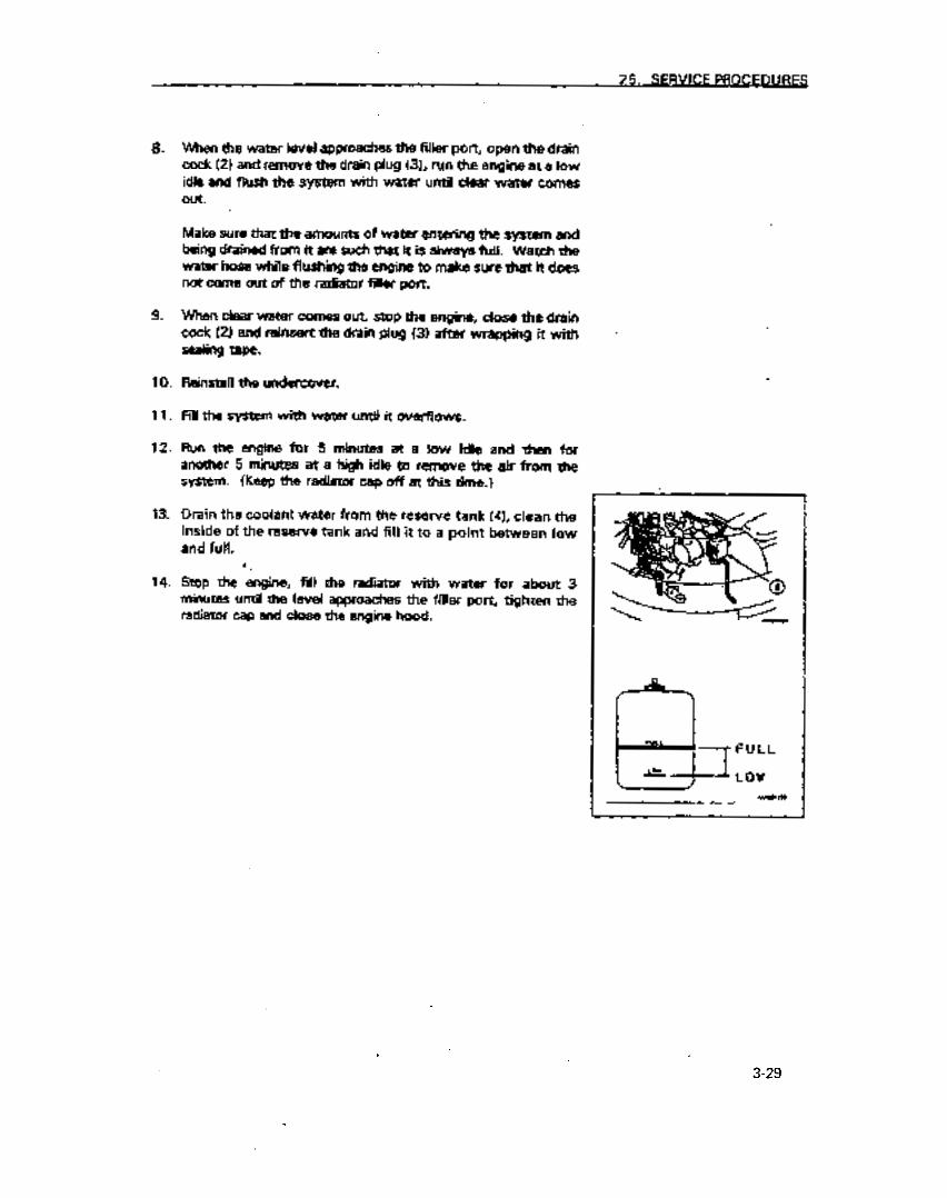
25. SERVICE PROCEDURES
8.
9.
10.
11.
12.
13.
14.
men the water level approaches the filler port, open the drain cock (2) and remove the drain plug (31, run the engine at a low idle and flush the system with water until clear water comes Out.
Make sure that the amounts of water entering the system and being drained from it are such that it is always full. Watch the water hose while flushing the engine to make sure that it does not come out of the radiif filler port.
When dear water comes out, stop the engine, dose the drain cock (2) and reinsert the drain plug (31 after wrapping it with sealing tape.
Reinstall the undercover.
Fill the system with water until it overflows.
Run the engine for 5 minutes at a low, idle and then for another 5 minutes at a high idle to remove the air from the system. (Keep the radiator cap off at this time.)
Drain the coolant water from the reserve tank (41, clean the inside of the reserve tank and fill it to a point between low and full.
Stop the *engine, fill the radiator with water for about 3 minutes until the level approaches the filler port, tighten the radiator cap and close the engine hood.
3-29
https://tractormanualz.com
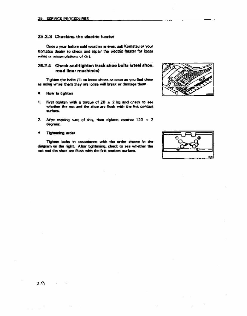
25. SERVICE PROCEDURES
25.2.3 Checking the electric heater
Once a year before cold weather arrives, ask Kometsu or your
Komatsu dealer to check and repair the electric heater for loose wires or accumulations of dirt.
25.2.4 Check and tighten &&k.%oe t&its isteei ih& road liner machines)
Tighten the bolts 11) on loose shoes as soon es you find them as using while them they are loose will break or damage them.
m
1.
2.
0
How to tighten
First tighten with a torque of 20 i 2 kg and check to see whether the nut and the shoe are flush with the link contact surface.
After making sure of this, then tighten another 120 f 2 degrees.
Tqhtening order
Tighten bolts in accordance with th+ order. shown in the diagram on the right. After tightening, check to see whether the nut and the shoe are flush with the link contact surface.
3-30
https://tractormanualz.com
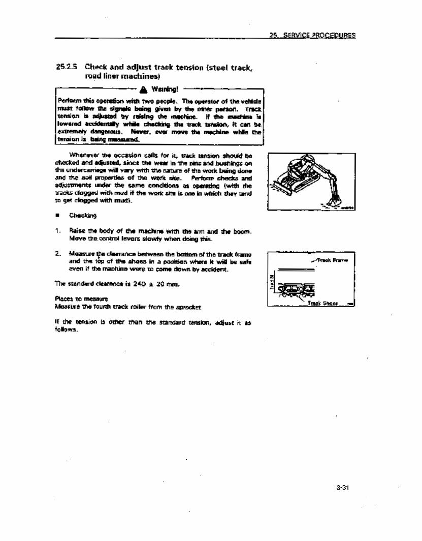
25. SERVICE PROCEDURES
25.2.5 Check and adjust track tension (steel track, road liner machines)
A Warning! -1
Perform this o@esation with two peeple. The operator of the vebide must follow the signals being given by the other person. Track tension is ecijusted by raising the machine. If ‘the machine is lowered accidentaliy while checking the track tension, it can be extremely dangerous. Never, ever move the machine while the tension is being. measured.
Whenever the occasion calls for it, track tension should be checked and adjusted, since the wear in the pins and bushings on the undercarriage will vary with the nature of the work being done and the soii properties of the work site. Perform checks and adjustments under the same conditions as operating (with the tracks dogged with mud if the work site is one in which they tend to get clogged witi mud).
l Checking
1. Raise the body of the machine with the arm and the boom. Move the. control levers slowly when doing this.
2. Measure Fe clearance between the bottom of the track frame and the top of the shoes in a position where it will be safe even if the machine were to come down by accident.
The standard clearance is 24.0 -c 20 mm.
Places to measure Measure the fourth track roller from the sprocket
If the tension is other than the standard tension, adjust it as follows.
/Track Fraim .
’ Track Shoes ‘(I
3-31
https://tractormanualz.com

25. SERVldE PROCEDURES
n Adjusting tension
A Warning!
There is the danger that the grease under high pressure inside the mechanism may fly out. Do not loosen the lubricator (1) more than 1 turn when loosening it. Do not loosen any other parts than the lubricator (1). at this time. Do not have your faoe in front of ths lubricator (1). If track tension is not relieved by fdlowing the procedures here, contact Komatsu or your Komatsu dealer fof essistence. I
0 How to increase tension
Prepare a grease gun.
1. Pump grease from the grease gun into grease fitting (21.
2. To check for the proper tension, move the machine backwards and forwards.
3. Check the t&ion of the track again and if it is still not as it should be adjust it again.
4. Pump grease in until S is 0 mm. If the tension is still too loose, there will be greater wear on the pins and bushings and they will need to be either reversed or replaced. Ask Komatsu or your Komatsu dealer for assistance in this repair.
3-32
https://tractormanualz.com
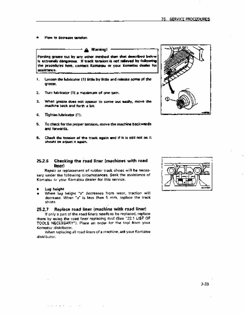
25. SERVICE PROCEDURES
l How to decrease tension
1.
2.
3.
4.
5.
6.
Loosen the lubricator (I 1 little by lie and release some of the grease.
Turn lubricator (1) a maximum of one turn.
When grease does not appear to come out easily, move the machine back and forth a bit.
lighten lubricator (1).
To check for the proper tension, move the machine backwards and forwards.
Check the tension of the track again and if it is still not as it should be adjust it again.
252.6 Checking the road liner)
liner (machines with road
Repair or replacement of rubber track shoes will be neces- sary under the following circumstances. Seek the assistance of Komatsu or your Komatsu dealer for this service.
n Lug height 0 When lug height “a” decreases from wear, traction will
decrease. When “a” is less than 5 mm, replace the track shoes.
25.2.7 Replace road liner (machine with road liner) If only a part of the road liners needs to be replaced, replace
them by using the road liner replacing tool (See “22.1 LIST OF TOOLS NECESSARY”). Place an order for the tool from your Komatsu distributor.
When replacing all’road liners of a machine, ask your Komatsu distributor.
3-33
. . : https://tractormanualz.com

25. SERVICE PROCEDURES
25.2.8 Replacing bucket teeth (vertical pin type)
Replace bucket teeth as they wear, before the bucket itself begins to wear.
A Warning!
It is dangerous if the arm and boom apparatus is accidentally moved while replacing bucket teeth. Place the arm and boom apparatus where it is stable and will not move, stop the engine and lock the control levers securely.
1.
2.
3.
Place blocks under the bottom of the bucket so that the pins of the teeth (1) may be removed. Make sure that the arm and boom apparatus is stable and lock the control levers. Place the bucket so that the bottom of the bucket is horizontal.
Use a hammer and punch and knock out the pin (2). (If the punch is facing the rubber pin lock (3) when you strike it, the rubber pin lock may break so face the back of the pin.)
Make sure that you have a locking pin (2) and a rubber pin lock (3) after you have removed the pin.
If you use the following kinds of locking pins and rubber pin locks, teeth may come off while the bucket is being operated. Replace them with new ones.
0 A locking pin which is too short
3-34
https://tractormanualz.com

25. SERVICE PROCEDURES
0 Rubber pin locks which have tears and whose steel balls will soon fall out.
_ Rubber is torn and
steel balls will come out
6 0 Steel bails go in when pressed by the hand.
presssd by hand
4. Remove dirt from the adapter with a putty knife.
5. Push the rubber pin lock into the adapter hole with your hand or a hammer.
Be careful when doing this so that the rubber pin lock does not fly off of the adapter.
6. Clean the inside face of tooth (al and install it on adapter (4). If it has mud on it or if it protrudes, the teeth will not go all the way into the adapter and there will not be good contact where they are supposed to be together.
7. Put the teeth [I 1 into adapter (41 and push the teeth in firmly and make sure that rear face of the pin hole of the teeth (1) is nearly in a straight line with the rear face of the adapter hole.
Things stuck on
E
3-35
https://tractormanualz.com

25. SERVICE PROCEDURES
If the rear hole face of the pin for tooth (1) is protruding out in front from the rear hole face of the pin for the adapter (4) do not pound the pin in. When this is the case, there is something that is preventing adapter (4) from getting all the way into tooth (1). This should first be found and removed and when the tooth (1) satisfactorily goes in the adapter, pound in the locking pin (2).
a. Place the locking pin (21 in the pin hole of the tooth and pound it until the top of the locking pin is the same height as the surface of the tooth (1).
9. Always check the following after replacing bucket teeth. 11 Check to make sure that the locking pin that has been
pounded in is secured by the tooth and the surface. 2) Tap the locking pin in the direction opposite to that which
it was pounded in. 31 Tap the tip of the tooth lightly up, down and from each
side.
4) The locking pin (2) and the rubber pin lock (3) must be in the positions shown in the diagram to the right.
The teeth will wear uniformly and life of them can be extended so that they are replaced less frequently by turning them over. Replace the rubber pin locks and locking pins at the same time you replace teeth. This will prevent the bucket from losing teeth.
3-36’
https://tractormanualz.com

25. SERVICE PROCEDURES
25.2.9 Replacing bucket teeth (horizontal pin type)
Replace bucket teeth as they wear, before the adapter begins to wear.
It is dangerous if the arm and boom apparatus is accidentally moved while replacing bucket teeth. Place the arm and boom apparatus where it is stable and will not move, stop the engine and lock the control levers
1. Place blocks under the bottom of the bucket so that the pins of the teeth (1) may be removed. Make sure that the arm and boom apparatus is stable and tack the control levers. Place the bucket so that the bottom of the bucket is horizontal.
2. Use a hammer and a rod and knock out and remove the pin (2).
Additional explanation
Use a round rod which is smaller in diameter than the pin.
3. Clean the surface where the tooth is to be mounted. Fii a new tooth in the adapter and insert pin (2) halfway. Pound it to attach the new tooth to the bucket.
Block
3-37
https://tractormanualz.com
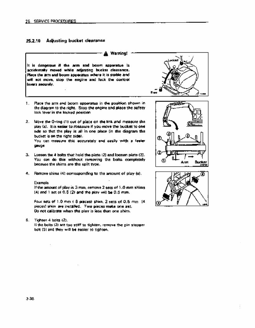
25. SERVICE PROCEDURES
25.2.10 Adjusting bucket clearance
A Warning!
It is dangerous if the arm and boom apparatus is accidentally moved while adjusting bucket clearance. Place the arm and boom apparatus where it is stable and will not move, stop the engine and lock the control levers securely.
1. Place the arm and boom apparatus in the position shown in the diagram to the right. Stop the engine and place the safety lock lever in the locked position
2. Move the O-ring (1 I out of place on the link and measure the play (a). It is easier to measure if you move the bucket to one side so that the play is all in one place (in the diagram the bucket is on the right side). You can measure this accurately and easily with a feeler gauge.
3. Loosen the 4 bolts that hold the plate (2) and loosen plate (3). You can do this without removing the bolts completely because the shims are the split type.
4. Remove shims (41 corresponding to the amount of play (a).
Example If the amount of play is 3 mm, remove 2 sets of 1 .O mm shims (41 and 1 set of 0.5 (2) and the play will be 0.5 mm.
Four sets of 1 .O mm ( 8 pieces) shim, 2 sets of 0.5 mm (4 pieces) shim are instailed. Two pieces make one set. Do not calibrate when the play is less than one shim.
5. Tighten 4 bolts (21. If the bolts (21 are too stiff to tighten, remove the pin stopper bolt (5) and they will be easier to tighten.
3-38-
https://tractormanualz.com

25. SERVICE PROCEDURE$
25.2.11 Check and repair the car cooler (if equipped)
a Warning!
The refrigerant is colorless and odorless and is harmless in the air but if it gets in the eyes or on the skin it could cause blindness or frostbite so never loosen any parts of the refrigerant lines.
e Check the amount of refrigerant (gas)
The air conditioner will not cool properly if there is insufficient refrigerant (gas). Normally there are no hubbies visible in the sight glass (for visual inspection) which is mounted on the receiver of the condenser unit in front of the oil cooler. When there are bubbles visible there is insuffitient refrigerant in the system. Have your dealer replenish the amount of refrigerant.
8 Clogging of the condenser
Cooling efficiency of the condenser will decline significantly if the condenser fins are dirt and caked with mud and dirt. Since the air conditioner’s cooling capabiliies will also decline, clean the mud and din from the condenser and when the fins are damaged, repair the driver etc.
e Cheoking when not in use
Run the compressor at low speed for a few minutes once a week in the off-season when the unit is not being used to supply lubricant to the various parts of the compressor. (When running the engine at low speed, turn the temperature control knob on the air condiiioner all the way to the left.
Be careful not to suddenly run the compressor at high speed when the temperature is cold outside as this will cause breakdowns. When the outside temperature is between 2 and 6.5OC the air compressor will not run even though the air conditioner switch is turned on.
3-39 :
https://tractormanualz.com

25. SERVICE PROCEDURES
25.2.12 Check and replenish wind shield washer fluid (if equipped)
If air gets into the windshieid washer fluid, check the amount of fluid in the reservoir (1) and if it is below the acceptable level, fill
reservoir with the washer fluid used in automobiles. Be careful so that no dirt gets in when filling.
the
Proportions to mixture water and washer fluid
Replenish the washer fluid by mixing with water according to following proportions which will differ depending on the the
ambient temperature.
Area, season Mixture ratio Freezing temperature
Normal Washer fluid l/3, 2/3 water -1O’C
Winter in a cold area Washer fluid 112, water 112 -2O’C
Winter in extremely cold areas -30-c
There are 2 types of washer fluid depending on the temperature at which it wilt freeze: -1OOC (for general use) and - 30°C (for use in colder areas). Select the one appropriate for your area and season.
3-4d
https://tractormanualz.com

25. SERVICE PROCEDURES
25.3 CHECKS BEFORE STARTING OPERATIONS
25.3.1 Check and replenish coolant level
A Warning!
Under normal circumstances, do not remove the radiator cap. Check the coolant level in the reserve tank when the engine is cold.
1.
2.
3.
Open the engine hood and check to see whether the coolant level in the reserve tank (1) is between FULL and LOW. (See diagram at right) If the level is low add coolant to reserve tank (1) until it is at the full level.
Tighten the cap securely when you have finished adding coolant.
If the reserve tank is empty check for leaks. Then check the coolant level in the radiator. If low add coolant to the radiator and then to the reserve tank.
25.3.2 Check the oil in the engine oil pan and add if needed
1. Open the engine hood.
2. Remove dipstick (G) and wipe it off with a rag. .
3. Reinsert dipstick (G) as far as it will go and then remove.
4. If there is oil on the dipstick (G) between H and L, the level is satisfactory. If the level is beiow L add oil at (F).
For the oil to use see item 21. “Use of fuel and lubricants by ambient temperatures”
EiicL IaLL FULL
&& LOW -IX -- -.. _.
~
k
‘
3-41
https://tractormanualz.com

25. SERVICE PROCEDURES
5. If the level is above H remove the excess oil from drain plug (PI and recheck the oil level.
6. If the oil level is correct, replace the cap, tighten it securely and close the engine hood.
Additional explanation
If you are checking the oil level after the engine has been operating, wait for at least 15 minutes after stopping the engine before performing the check.
25.3.3 Check the fuel level
Do not allow the fuel tank to overflow when refueling as thii can Clean up any spillage if it occurs. Do not stand
directly above the opening to the fuel tank when refueling. 1 may spurt out from the tank breather hole. I
1. Insert the key in the ignition switch (I), turn it to the ON position and allow the monitor light to come on.
2. Ascertain the amount of fuel remaining from the fuel gauge 12). If there is insufficient fuel, fill the fuel tank while observing the sight gauge (G).
Capacity of fuel tanks 135 0
For the fuel you should use see item 21. “Use of fuel and lubricants by ambient temperatures”
3. After finishing, replace the cap and tighten it securely.
Additional expianation
If the breather holes (3) become clogged, pressure in the tank will decrease and fuel will not flow. Clean these holes from time to time.
3-42:.
https://tractormanualz.com

25. SERVICE PROCEDURES
25.3.4 Check and replenish the oil in the hydraulic oil tank
A Warning! ‘~1
l Unscrew the cap to the hydraulic tank slowly and allow
1. If the vehicle is not as shown in the diagram on the right, start the engine and while it is running at low speed, lower the blade to the ground, retract the arm and bucket cylinders, lower the boom and stop the engine with the teeth of the bucket touching the ground.
2. Check sight gauge tG) and if the oil level is between H and L, it is satisfactory.
NOTICE
Do not add oil above the H line. This will damage the hydraulic lines and will cause oil to spurt out.
3. if the hydraulic oil level is below L, remove the cover on the top of the hydraulic oil tank, and add oil from filler port (PI
For the oil you should use see item 21. “Use of fuel and lubricants by ambient temperatures”
Additional explanation
The oil level will vary with the temperature of the oil so use the following criteria to check the oil
3 =I H
L
0 Prior to operation, around the L level (oil temperature from 10 - 300C)
0 During normal operation, near the H level (oil temperature from 50 to 80°C)
3-43
https://tractormanualz.com
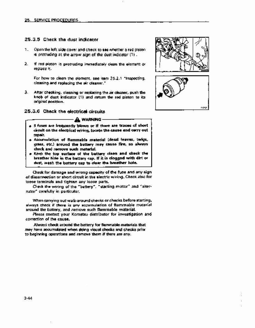
25. SERVICE PROCEDURES
25.3.5 Check the dust indicator
1. Open the left side cover and check to see whether a red piston is protruding at the arrow sign of the dust indicator (1) .
2. If red piston is protruding immediately clean the element or replace it.
For how to clean the element, see item 25.2.1 “Inspecting, cleaning and replacing the air cleaner.”
3. After checking, cleaning or replacing the air cleaner, push the knob of dust indicator (I) and return the red piston to its original position.
25.3.6 Check the electrical circuits
r A WARNING
If fuses are frequently blown or if there are traces of short circuit on the electrical wiring, locate the cause and terry out repair. Accumulation of flammable material (dead leaves, twigs, grass, etc.1 around the battery may cause fire, so always check and remove such material.. Keep the top surface of the battery dean and check the breather hble in the battery cap. lf it is clogged with dirt or dust, wash the battery cap to clear the breather hole.
Check for damage and wrong capacity of the fuse and any sign of disconnection or short circuit in the electric wiring. Check also for loose terminals and tighten any loose parts.
Check the wiring of the “battery”, “starting motor” and “alter- nator” carefully in particular.
When carrying out walk-around checks or checks before starting, always check if there is any accumulation of flammable material around the battery, and remove such flammable material.
Please contact your Komatsu distributor for investigation and correction of the cause.
Always check around the battery for flammable materials that may have accumulated when doing visual checks and checks prior to beginning operations and remove them if there are any.
3-44
https://tractormanualz.com
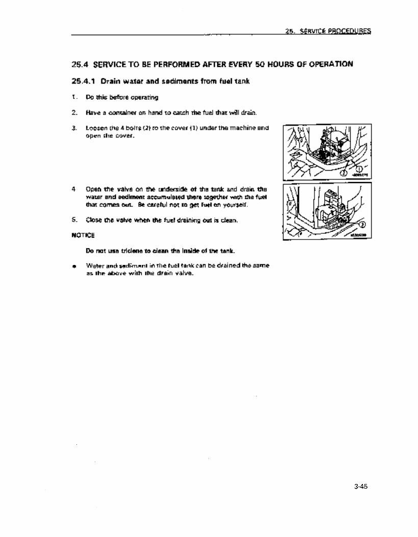
25. SERVICE PROCEDURES
25.4 SERVICE TO BE PERFORMED AFTER EVERY 50 HOURS OF OPERATION
25.4.1 Drain water and sediments from fuel tank
7.
2.
3.
4.
5.
Do this before operating
Have a container on hand to catch the fuel that will drain.
Loosen the 4 bolts (2) to the cover (1) under the machine and open the cover.
Open the valve on the underside of the tank and drain the water and sediment accumulated there together with the fuel that comes out. Be careful not to get fuel on yourself.
Close the valve when the fuei draining out is clean.
NOTICE
Do not use triclene to dean the inside of the tank.
0 Water and sediment in the fuel tank can be drained the same as the above with the drain valve.
3-45
https://tractormanualz.com
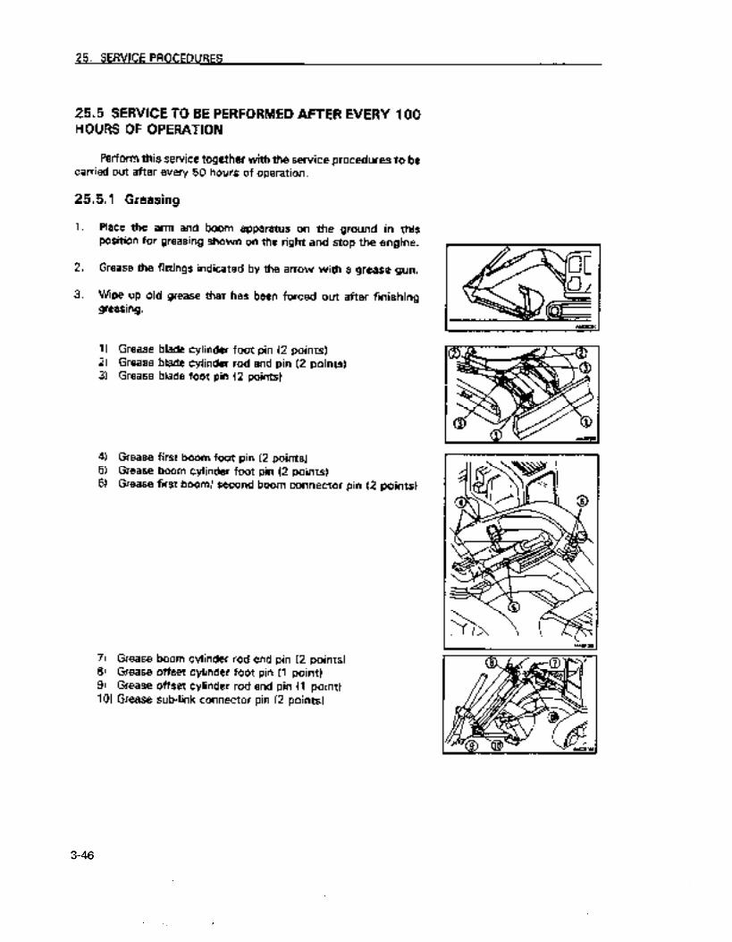
25. SERVICE PROCEDURES
25.5 SERVICE TO BE PERFORMED AFTER EVERY 100 HOURS OF OPERATION
Perform this service together with the service procedures to be carried out after every 50 hours of operation.
25.5.1 Greasing
1. Place the arm and boom apparatus on the ground in this position for greasing shown on the right and stop the engine.
2. Grease the fittings indicated by the arrow with a grease gun.
3. Wipe up old grease that has been forced out after finishing greasing.
I) Grease blade cylinder foot pin (2 points) 2) Grease blade cylinder rod end pin (2 points) 3) Grease blade foot pin (2 points)
4) Grease first boom foot pin (2 points) 5) Grease boom cylinder foot pin (2 points) 6) Grease first boom/ second boom connector pin (2 points)
7) Grease boom cylinder rod end pin (2 points) 8) Grease offset cylinder foot pin (1 point) 9) Grease offset cylinder rod end pin (1 point) 101 Grease sub-link connector pin (2 points)
3-46
https://tractormanualz.com

25. SERVICE PROCEDURES
11) Grease second boom third bracket connector pin (2 points) 12) Grease arm cylinder foot pin (2 points) 13) Grease arm cylinder rod end pin (I point) 14) Grease third bracket/ arm connector pin (1 point)
15) Grease bucket cylinder foot pin (1 point) 16) Grease bucket cylinder rod end pin (1 point) 17) Grease arm/ link connector pin (. 1 point1 18) Grease link connector pin (2 points) 191 Grease bucket/ link connector pin (2 points) 201 Grease arm/ bucket connector pin (1 point)
4. Move the boom up and down a number of times after greasing and then grease the first boom foot pin (2 points) again.
3-47
https://tractormanualz.com

25. SERVICE PROCEDURES
25.5.2 Check and replenish the oil in the swing machinery case
A Warning!
Oil is hot after operating the machine. Begin this operation after the oil has cooled down.
i. Open the engine hood and the center hood. Open the cover in the bottom of the tool box.
2. Remove the dipstick (G) and wipe it off with a rag.
3. Reinsert the dipstick (G) as far as it will go.
4. Remove the dipstick. If there is oil on the dipstick (G) between H and L, the ;evel is satisfactory.
5. If the level is below L. Reinsert the dipstick and add engine oil at filler port (F). Remove the air bleeder plug (21 while adding oil.
For the oil to use see item 21. “Use of fuel and lubricants by ambient temperatures”
6. If the level is above H, loosen the drain plug (PI and remove the excess oil.
7. After checking and replenishing the oil, reinsert the dipstick and reinstall the drain plug (2).
3-48
- https://tractormanualz.com
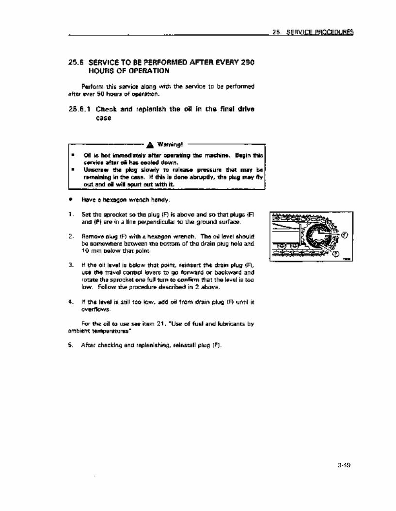
25. SERVICE PROCEDURES
25.6 SERVICE TO BE PERFORMED AFTER EVERY 250 HOURS OF OPERATION
Perform this service along with the service to be performed after ever 50 hours of operation.
25.6.1 Check and replenish the oil in the final drive case
A Warning!
0 Oil is hot immediately after operating the machine. Begin this service after oil has cooled down.
0 Unscrew the plug slowly to release pressure that may be remaining in the case. If this is done abruptly, the plug may fly out and oil will spurt out with it.
0
1.
2.
3.
4.
Have a hexagon wrench handy.
Set the sprocket so the plug (FI is above and so that plugs (Fl and (PI are in a line perpendicular to the ground surface.
Remove plug (R with a hexagon wrench. The oil level should be somewhere between the bottom of the drain plug hole and 10 mm below that point.
If the oil level is below that point, reinsert the drain plug (Fl, use the travel control levers to go forward or backward and rotate the sprocket one full turn to confirm that the level is too low. Follow the procedure described in 2 above.
If the level is still too low, add oil from drain plug (Fl until it overflows.
For the oil to use see item 21. “Use of fuel and lubricants by ambient temperatures”
5. After checking and replenishing, reinstall plug (F).
3-49
https://tractormanualz.com
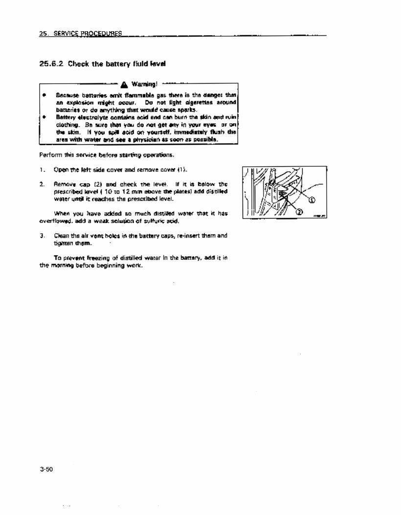
25. SERVICE PROCEDURES
25.6.2 Check the battery fluid level
I- A Warning!
0 Because batteries emit flammable gas there is the danger that an explosion might occur. Do not light cigarettes around
batteries or do anything that would cause sparks. 0 Battery electrolyte contains acid and can burn the skin and ruin
clothing. Be sure that you do not get any in your eyes or on
the skin. If you spill acid on yourself, immediately Rush the
area with water and see a physician as soon as possible.
Perform this service before starting operations.
1. Open the left side cover and remove cover (1 I.
2. Remove cap (2) and check the level. If it is below the prescribed level ( 10 to 12 mm above the plates) add distilled
water until it reaches the prescribed level.
‘When you have added so much distilled water that it has
overflowed, add a weak solution of sulfuric acid.
3. Clean the air vent holes in the battery caps, m-insert them and
tighten them. ’
To prevent freezing of distilled water in the battery, add it in
the morning before beginning work.
3-50
https://tractormanualz.com

25. SERVICE PROCEDURES
25.6.3 Replace the oil in engine oil pan and replace the engine oil filter cartridge
A Warning!
Do not change the oii immediately after the engine has been operating as all parts of the engine are hot. Change the oil sfter it has cooled down
Have on hand: 0 A container to catch the drained oil that will hold at least 12 e 0 12eofoil l An oil filter wrench
1. Remove the cover on the underside of the machine.
2. Place the contain directly under the drain plug (PI located on the underside of the machine.
3. Loosen and then remove the drain plug slowly so that you do not get any oil on yourself and allow the oil to drain out.
4. Check the drained oil and if there is a large amount of metal particles or foreign matter in it seek the assistance of Komatsu or your Komatsu dealer.
5. Reinstall drain plug (PI and reinstall the cover on the underside of the machine.
6. Open the engine hood and from above the engine use a filter wrench to turn the oil filter cartridge (3) to the left. A large amount of oil will come out if you do this immediately after YOU stopped the engine so wait about 10 minutes before doing this.
7. Clean the mount for the filter and apply a fight coating of oil to the surface of the seal or gasket of the new filter cartridge (or coat in with a thin layer of grease) and install the new filter cartridge.
8. After placing the filter cartridge on the mount and the packing surface contacts the seal surface, tighten it at least 3/4 turn.
3-51
https://tractormanualz.com
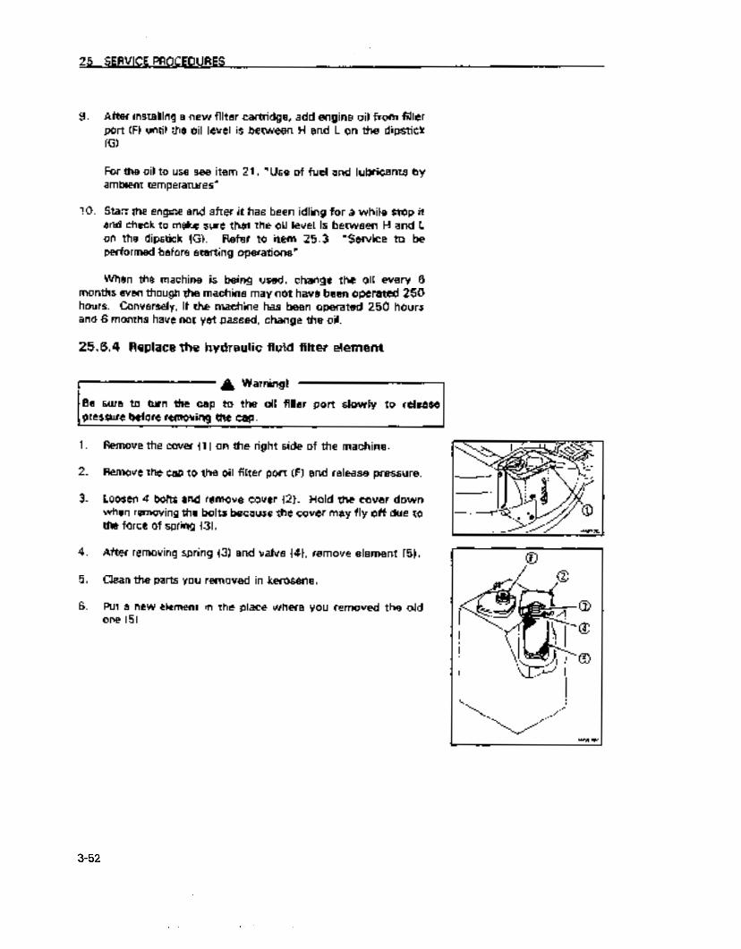
25. SERVICE PROCEDURES
9.
10.
After installjng a new filter cartridge, add engine oil from filler port (F) until the oil level is between H and L on the dipstick (G)
For the oil to use see item 21. “Use of fuel and lubricants by ambient temperatures”
Start the engine and a f-t r it alias been idling for a whiie stop it e -
and check to make sure that the oil level is between H and L on the dipstick (G). Refer to item 25.3 “Service to be performed before starting operations”
When the machine is being used, change the oil every 6 months even though the machine may not have been operated 250 hours. Conversely, if the machine has been operated 250 hours and 6 months have not yet passed, change the oil.
25.6.4 Replace the hydraulic fluid filter element
I-- A Warning!
Be sure to turn the cap to the oil filler port slowly to release pressure before removing the cap.
1. Remove the cover (1) on the right side of the machine.
2. Remove the cap to the oil filter port (9 and release pressure.
3. Loosen 4 bolts and remove cover (2). Hold the cover down when removing the bolts because the cover may fly off due to the force of spring (3).
4. After removing spring (3) and valve (41, remove element (5).
5. Clean the parts you removed in kerosene.
6. Put a new element in the place where you removed the old one (5)
3-52
https://tractormanualz.com

25. SERVICE PROCEDURES
7. Place valve (4) and spring (31 on top of the element
8. Place the cover in position, and tighten the mounting bolts while pushing it down with your hand.
9. Extend the cylinders of the boom, arm and bucket as shown in the diagram on the right, and after having removed the filler cap, reinstall the cap and pressurize the tank.
10. Reinstall cover (1).
Deterioration of hydraulic fluid is much more rapid when hydraulic breakers are installed than with normal bucket excavation operations. Replace the element between 100 and 150 hours for the first time on a new machine and then replace the element in accordance with the table on the right. Replace the additional filter element for use with a breaker (optional) in accordance with the table on the right with every 250 hours of breaker use as a guideline (when the breaker is operated more than 50 O/O of the time)
3-53
https://tractormanualz.com

25. SERVICE PROCEDURES
25.6.5 Check and adjust the tension of the car cooler
compressor belt
n Checking
The belt should give about 12-15 mm when pressed with the
finger (about 6 kg) between the drive pulley and the compressor pulley.
= Adjusting
Have the following available: a A bar 0 A piece of wood
7.
2.
3.
4.
5.
6.
7.
Place the bar in between the compressor (1 I and the bracket
to secure the compressor (7 1 in place. When doing this place
a piece of wood between the bar and the compressor 111 so
that the compressor will not sustain any damage.
Loosen ix&s (2) and (3).
Move the compressor so that the belt will give about 12- 15
mm when pushed with a force of approximately 6 kg.
Tighten bolts 121 and (31 to hoid the compressor (11 in place.
Check for damage to each of the pulleys, for wear of the
groove and wear to the belt. In particular, makesure that the
belt is not touching the bottom of the groove in the pulley.
Replace the belt if it is stretched and has no room for
adjustment or if it is cut or cracked.
After you have replaced a belt, readjust it after running the engine for an hour.
Compressor pulley
Piece of wood aar
3-54
1. . . ._ -.*_. I https://tractormanualz.com

25. SERVICE PROCEDURES
25.7 SERVICE TO BE PERFORMED AFTER RIERY 500 HOURS OF OPERATION
Perform this service together with the service to be performed afier every 50, 100 and 250 hours of operation.
25.7.1 Replace fuel filter cartridge
A Warning! q-1
e Do not replace Btter immediately after the engine has been running as all of the components are hot. Do this after the engine has cooled down.
0 Be careful of open flames and cigarettes and do not have them nearby.
0 When cranking the engine to bleed out air, make sure that the area around the engine is sefe because the engine may start.
. Have a f&x wrench and a container for catching fuel on hand for the procedure.
1.
2.
3.
4.
Place the container under the fuel fiiter cartridge.
Turn the fuql filter cartridge (1) to the left with a filter wrench and remove it
Clean the filter mounting and fill the new filter cartridge with fuel. Coat the packing surface with oil and install the cartridge in the fiitfx mounting.
After placing the fiiter cartridge on the mount and the packing surface contacts the seal surface, tighten it approximately 213 of a turn.
Tighten the filter the proper amount because if it is tightened too much, the packing .wiU be damaged which will lead to a fuel leak. If the filter is too I6ose it will also leak.
5. BIeed air from the system after the new cartridge has been installed.
Bleed the air using the following procedure.
3-55
https://tractormanualz.com
25. SERVICE PROCEDURES
6. Fill the fuel tank completely (until the fuel level gauge is at the FULL position).
7.
8.
After replacing filter cartridge (11, loosen joint bolt (2).
Loosen the knob of feed pump (3), then move it up and down until no more bubbles come out with the fuel from joint bolt (2).
9. Tighten joint bolt (2). Always use a Komatsu genuine cartridge for the filter cartridge. After replacing the filter cartridge, start the engine and check for leakage of fuel from the filter seal.
Additional explanation
If the machine runs out of fuel, operate the feed pump in the same way to bleed the air.
. 3-56
https://tractormanualz.com

25. SERVICE PROCEDURES
25.7.2 Check and replenish the amount qf grease in the swing pinion
8 Have a scale available for this procedure.
1. Remove botts (21 on the top of the revolving frame and remove cover (2).
2. Insert a scale in the grease and check to see whether the amount of grease in the potion where the pinion passes is at least 28 mm high. If it is below this level add grease.
3. Check to see whether the grease is milky white. If it is the grease should be replaced. Seek the assistance of Komatsu or your Komatsu dealer for this service.
The total volume of grease is 6.5 e (6 kgi
4. Re-install cover (2) with bolt (1).
25.7.3 Grease the swing circle (2 points)
1. Place the arm and boom apparatus on the ground.
2. Grease the grease fittings indicated by the arrows in the diagram on the right with a grease gun.
3. Wipe up old grease that was forced out after finishing the greasing.
3-57
https://tractormanualz.com
25. SERVlCE PROCEDURES
25.7.4 Check and dean radiator fins, oil cooler fins and condenser fins
1 A Warning!
‘There is danger of injury from compressed air, steam or water striking the body. Wear safety goggles, masks and safety shoes etc.
1. Open the engine hood and the left side cover of the machine.
2. Blow dust, dirt, leaves and mud dogged in the fins of the radiator, oil cooler and condenser off with compressed air. In addition clean the net in front of the oil cooler at thii time. You may use steam or water in place of compressed air.
3. Check rubber hoses and replace those which have cracks or are brittle. Check for loose hose _clamps as well.
NOTICE
When using compressed air. stand back to avoid damaging the fins. If the fins are damaged, this will teed to water leaks and may cause overheating. Perform this prooedure every day when working in a work site with a lot of dust, regardless of the suggested service interval.
3-58
https://tractormanualz.com

25. SERVICE PROCEDURES
25.75 Clean car cooler filters
1. Pull fiitei (1) up and remove.
2. Clean filter 11) with compressed air. If the filter is soiled with oil of’ is extremely’ dirty, wash it in water with a neutral washing solution. After washing it, dry it thoroughly before using iL
If clogging of the filter cannot’be solved by cleaning with air or by washing, replace it with a new one.
NOTICE
Cleaning after 500 hours of opaetion is a generel standard. If the work site where the machine is operated is dusty, dean the filter more frequentiy.
3-59
https://tractormanualz.com
35 . SERVICE PROCEDURES
25.7.6 Clean filter at bottom of fuel tank,.drain water
1. 2. 3.
4.
5.
6.
7.
L
and sediment Carry out this operation before starting operations.
Put a container in position to catch the fuel that is drained.
Loosen 2 bolts (2) of cover (1) under the chassis, then open the
cover.
Turn lever (4) of drain valve (3) under the tank to set the arrow
facing 9O”Cdown. Drain the fuel together with the sediment and
water. When doing this, be careful not to get fuel on yourself.
Loosen nut (5) and drain the fuel from inside the fuel circuit (hose,
valve). Remove bolt (6). take out filter (7) from inside, then wash filter (7).
After washing fitter (7). assemble it again and install it with bolt (6).
Drain the water and sediment collected at the bottom of the tank as
foltows. 1) 2)
Turn lever (4) a further 9O”Cto set the arrow facing to the right.
When only clean fuel comes out, turn lever (4) 180“Cto set fhe
arrow facing to the left. 3) Tighten nut (5).
NOTICE Never use trichloroethylene.
Fuel tank drain valve
imen ____ removing
ai,Q
:__, ’ filter
3-60
https://tractormanualz.com

25. SERVICE PROCEDURES
25.8 SERVICE TO BE PERFORMED AFTER EVERY 1000 HOURS OF OPERATION
Perform this service together with the service to be performed after every 50, 100 250, and 500 hours of operation.
25.8.1 Replace the oil in swing machinery case
A Warning!
Oil is hot after operating the machine. Begin this operation after the oil has cooled down.
Have the following on hand for this operation. 0 A container to catch the oil to be drained at least 2.5 P 0 2.5 P of new oil
1. Place the container for catching the drained oil under drain plug (PI under the vehicle.
2. Remove the drain plug (PI and after the oil has drained, reinsert it and tighten it up again. The tightening torque for the drain plug is 10 to 19 kgm.
3. Open the engine hood and the center hood. Open the cover in the bottom of the tool box (1). Remove the dipstick (G) and the air bleeder plug. Add the prescribed amount of oil from the place where the dipstick is normally inserted (FI.
For the oil to use see item 21. “Use of fuel and lubricants by ambient temperatures”
4. After.adding the oil, reinstall the air bleeder plug.
5. Wipe off the dipstick (G) with a rag.
6. Reinsert the dipstick (G) as far as it will go and remove it.
7. If there is oil on the dipstick (G) between H and L, the level is satisfactory. If the level is below L add from the same place as before (R. Remove the air bleeder plug (2) while adding oil.
3-61
https://tractormanualz.com

25. SERVICE PROCEDURES
6. If the level is above H loosen drain plug (PI and remove the excess oil and recheck the oil level.
Additional explanation
When checking the oil after operating the machine, wait 15 minutes after stopping the engine to do the check.
If the vehicle is on an incline, move it to a level place and then perform the check.
25.8.2 Replace oil in final drive case
A Warning!
0 Oil is hot immediately after operating the machine. Begin this service after oil hes cooled down.
0 Unscrew the plug slowly to release pressure that may be remdning in the case. If this is done abruptly. the plug may fiy outandoilwiaspurtwtwithit.
Have the following on hand for this procedure 0 A container to catch the oil to be drained at least 2.5 P 0 2.5 P of new oil for each right and left 0 A hexagon wrench
1. Set the sprocket so the plug (PI is above and so that plugs (PI and (PI are in a line perpendicular to the ground surface.
2. Place the container to catch the oil under plug (PI
3. Remove plugs (PI and (p) with a hexagon wrench. Drain the oil.
4. Reinsert plug (PI and tighten it.
5. Add the prescribed amount of oil from plug !Fl
Far the oil to use see item 21. “Use of fuel and lubricants by ambient temperatures”
6. Add oil from drain plug (PI until it overflows. Reinstall plug (0.
3-62
. . https://tractormanualz.com

25. SERVICE PROCEDURES
25.8.3 Check, adjust fan belt tension A special tool is needed to check and replace the fan belt, so
please ask your Komatsu distributor to carry out the operation.
25.8.4 Check all tighteners on the Turbocharger
Seek the assistance of Komatsu or your Komatsu dealer for this service.
g5.8.5 Check the play of the turbocharger rotor
258.6 Grease fuel stop solenoid linkage
1. Use a grease gun to grease the grease fitring indicated by the arrow.
2. After greasing, wipe off old grease that has been forced our.
Seek the assistance of Komatsu or your Komatsu dealer for this service
3-63
https://tractormanualz.com
25. SERVICE PROCEDURES
25.9 SERVICE TO BE PERFORMED AFTER EVERY 2000 HOURS OF OPERATION
Perform thii service together with the service to be performed after every 50, 100,250, 500 and 1000 hours of operation.
25.9.1 Check and replenish the oil in the PTO gear case
A Warning! *
Oil is hot after operating the machine. Begin this operation after the oil has cooled down.
1. Swing the superstructure and arm and boom apparatus so that the PTO gear case will be midway between the two tracks. Stop the engine and place the safety lock lever in the locked position
2. Remove the cover on the lower right side of the machine.
3. Remove plug (G1 and check to see whether the oil is close to the lower lip of the plug hole. If it is it is okay. When the oil level is lower than this, remove plug (F), and add oil from the hole for plug IFI until it comes up to the lower lip of the hole for plug (G).
For the oil to use see item 21. “Use of fuel and lubricants by ambient temperatures”
4. Re-install plugs (G) and (F).
5. Re-install the cover.
3-64
https://tractormanualz.com

25. SERVICE PROCEDURES
25.9.2 Replace hydraulic tank oil and clean strainer
A Warning!
Do not change the oil immediately after the engine has been operating as all parts of. the engine are hot. Change the oil after it has coded down
Unscrew the cap to the hydraulic tank slowly and allow pressure to escape before removing it as oil can spurt out at this time.
Have on hand: l . A container to catch the drained oil that will hold at least 82 0 0 82 e of new oil 0 A handle for socket wrenches
1. Swing the superstructure and arm and boom apparatus so that the drain plug for draining hydraulic fluid will be midway between the two tracks.
2. L If the vehicle is not as shown in the diagram on the right, start
3.
4.
5.
the engine and while it is running at low speed, lower the blade to the ground, retract the arm and bucket cylinders, lower the boom and stop the engine with the teeth of the bucket touching the ground.
Lower the blade to the ground, place the safety lock lever in the locked position and stop the engine.
Remove the cover (I) from the right side of the vehicle, and remove the cap on filler port (F).
Place the container for catching the oil under the drain plug under the vehicle. Using a socket wrench, remove the drain plug IPI and drain the hydraulic oil. Check the O-ring on the drain plug (P) and replace it if it is damaged. After draining. the oil, re-instatl the drain plug (PI and tighten.
Tightening torque is 7 2 1 kgm.
Be careful so that you do not get oil on you when you remove drain plug (PI.
3-65
https://tractormanualz.com

25. SERVICE PROCEDURES
6.
7.
a.
9.
10.
11.
Remove 4 bolts and remove cover (2). Hold the cover down while removing the bolts as the cover may fly off from the force of spring (3).
Pull the top of rod (41 up, and take out the spring (3) and the strainer (5).
Knock off any dirt that is stuck to the strainer (51, and clean it in clean kerosene or a cleaning oil. Replace the strainer (5) if it is damaged.
Re-insert the strainer (5) into the part of the tank that is protruding (6).
Bolt down cover (2).
Add the prescribed amount of engine oil at filler port (PI. Check to make sure that the level is between H and L on the sight gauge.
For the oil to use see item 21. “Use of fuel and lubricants by ambient temperatures”
12.
13.
As shown in the diagram on the right extend the boom, arm and bucket cylinders fully and after removing the cap to the filler port, reinstall it again and then pressurize the tank.
After changing oil, put each of the control levers in neutral, run the engine at a tow idle for 2 to 3 minutes and then proceed with operations.
3-66
https://tractormanualz.com
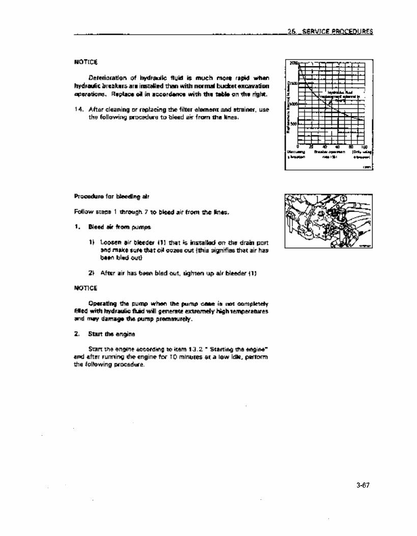
NOTICE
Deterioration of hydraulic fluid is much more rapid when hydraulic breakers are installed than with normal bucket excavation operations. Replace oil in accordance with the table on the right.
14. After cleaning or replacing the filter element and strainer, use the following procedure to bleed air from the lines.
Procedure for bleeding air
Follow steps 1 through 7 to bleed air from the lines.
1. Bleed air from pumps
1)
21
Loosen air bleeder (1) that is installed on the drain port and make sure that oil oozes out (this signifies that air has been bled out)
After air has been bled out, tighten up air bleeder (1)
NOTICE
Operating the pump when the pump case is not completely filled with hydraulic fluid will generate extremely high temperatures and may damage the pump prematurely.
2. Start the engine
Start the engine according to item 13.2 ” Starting the engine” and after running the engine for 10 minutes at a low idle, perform the following procedure.
3-67
https://tractormanualz.com

25. SERVICE PROCEDURES
3. Bleed air from the cylinders
1 I Run the engine at a low idle, and extend and retract each cylinder without going all the way to the end of the stroke (stop at approximately 100 mm from the end of the stroke)
21 Next, move each cylinder to the end of its stroke 3 or 4 times.
31 Then move each cylinder to the end of its stroke 4 or 5 times and bleed the air out completely.
NOTICE
If the engine is initially run at high RPM and the cylinders are allowed to go to the end of their strokes, the piston packing etc. will be damaged by the air in the cylinder.
4. Bleed the air from the swing motor
(Do this only when the oil has been replaced in the swing motor case)
1)
NOTICE
Run the engine at a low idle, loosen air bleeder plug 11) and make sure that oil oozes out from the air bleeder plug (!I (this signifies that air has been bled out)
Do not swing the superstructure and arm and boom apparatus at this time.
2)
31
41
If oil does not ooze out, stop the engine, remove air bleeder plug (1) and fill the motor case with hydraulic fluid.
After the air has been completely bled out, m-insert air bleeder plug (1) and tighten.
Run the engine at a low idle and swing the superstructure and arm and boom apparatus slowly and steadily to the right at least 2 times.
NOTICE
Failure to bleed the air from the oil in the swing motor may damage the bearings in the motor.
3-68’
https://tractormanualz.com

5. Bleed air from the travel motor (do this only after replacing oil in the travel motor case)
1)
2)
3)
Run the engine at a low idle and detach hose (1) from C. If oil flows out m-attach it.
P0r-t
25. SERVICE PROCEDURES
I DOft c 1
Keeping the engine running at a low idle, swing the superstructure and arm and boom apparatus 90° so that it is perpendicular to the tracks.
Slowly brace the machine so that a track is slightly raised and run it without a load for 2 minutes and repeat this on both sides. When running the track without a load move it an equal amount forward and reverse.
6. Bleed air from attachments (When installed)
When breakers and other attachments are installed, run the engine at a low idle, repeatedly manipulate the attachment pedal (about 10 times) and bleed the air out until air has been completely bled from both the attachment and the lines.
NOTICE
When the manufacturer has stipulated a specific procedure for bleeding air from the attachment, follow that procedure.
7. Operation
11
2)
After the air has been bled out from the systems, stop the engine and after waiting at least 5 minutes to resume, start then engine and resume operations. This will allow air bubbles in oil in the tank to escape.
Check to make sure there are no leaks. Wipe up any oil that was spilled.
3-69
https://tractormanualz.com
25. SERVICE PROCEDURES
25.9.3 Clean and check turbocharger
Seek the assistance of Komatsu or your Komatsu dealer for this service.
25.9.4 Check the alternator/ starter
Seek the assistance of Komatsu or your Komatsu dealer for this service. There is a possibility that brushes have worn and that the bearings have run out of grease. Have this done every 1000 hours if the engine is started frequently.
25.9.5 Check and adjust engine valve clearance
As this requires special tools, seek the assistance of Komatsu or your Komatsu dealer for this service.
3-70;
https://tractormanualz.com

25.10 SERVICE TO BE PERFORMED AFTER EVERY 4000 HOURS OF OPERATION
Perform this service together with the service to be pelformed after every 50,100,250,500,1000 and 2000 hours of operation.
25.10.1 Check the water pump
Since the pulley (I) may have play, oil may leak, water may leak and the drain hole (2) may be clogged, contact your Komatsu distributor for inspection, overhaul or replacement.
3-71
https://tractormanualz.com

26.1 Before beginning work (Checks prior to starting operations)
Check the functioning of the brakes and the clutch.
26.1.1 At least monthly
1. Whether or not there is abnormal operation of the brakes, d&h, control devices or apparatus. 2. Whether or not there is damage to wire rope and chain etc. 3. Whether or not there is damage to the bucket
26.2 Checks before beginning work (Checks prior to starting operations)
26.2.1 At least monthly
1. ~herornatthereisabnormaloperation05thebrakes,dutch,~devicesorapparatus. 2. Whether or not there is damage to wire rope and chain e&. 3. Whether or not there is damage to the bucket 4. Whether or not there is damage to warning and security devices
26.2.2 At least annually
Abnormalities of each component
3-72-
https://tractormanualz.com

SPECIFICATIONS
4-7
https://tractormanualz.com

27. SPECIFICATIONS
l PC128UU-1
Weight
Vehicle with steel tracks Vehicles with road liner
l Operating weight.Lnot including the operator)
Performance
l Bucket capacity (standard bucket)
13,100 kg (28886 lb) 13,200 kg (29106 lb)
0.4 m’ (0.52 cu.yd)
l Width
l Travel speed
l Swing speed
(Standard bucket)
(With side cutter)
(Low speed)
(High speed)
833 mm (2 ft 9 in)
953 mm (3 ft 2 in)
2.4 km/h (1.5 MPH)
4.0 km/h (2.5 MPH)
10 rpm
Tracks
l Rubber tracks
Engine
Road liner Triple grouser tracks 500 mmtl ft 8 in) 506 mm (1 ft 8 in)
l Model Komatsu S4D102E-1
l Flywheel horsepower
0 Starting motor
l Alternator
l Battery
62.5 kW/1900 rpm (84 HP/1900 rpm)
24 V 4.5 kW
24 V 25 A
2. 12 V 80 Ah
4-2
https://tractormanualz.com

27. SPECIFICATIONS
l Vehicles with road liner Figures not in parentheses are those for vehicles with road liner l Vehicles with steel tracks Figures in parentheses are those for vehicles with steel tracks
Figures standing alone with corresponding figures in parentheses are the same for vehicles with road liner and vehicles with steel tracks
2
ti --t-l (SIP)SPP aDueJea(i punoJ6 *u!yy
0 N N
O4 ll? L rr N
4-3
https://tractormanualz.com

27. SPECIFICATIONS
l Vehicles with road liner Figures not in parentheses are those for vehicles with road liner 0 ,Vehicles with steel tracks Figures in parentheses are those for vehicles with steel tracks
Figures standing alone with corresponding figures in parentheses are [he Same for vehicles with road liner and vehicles with steel tracks
_ .
3 c N c
I I (068S)O56S ’ (06E lOEt7E
4-4
https://tractormanualz.com

OPTIONAL PARTS, ATTACHMENTS
https://tractormanualz.com

28. GENERAL PRECAUTIONS
28.1 SAFETY PRECAUTIONS
Use of attachments that have not been authorized by Komatsu will not only adversely affect the proper operation of the machine and the useful liie of the machine but may also create safety problems. If you are going to install attachments that are not in this manual consult with Komatsu or your Komatsu dealer in advance. Komatsu will not be responsible for any injuries, accidents or equipment breakdowns that are caused by the use of unapproved attachments if you do not contact them in advance.
A Warning!
Precautions in installing and removing
Observe the following precautions when removing and installing attachments and perform the operation safely.
0 Remove or install attachments on firm, level ground. 0 If the operation is to be done together by 2 or more persons, decide on signals in advance and
follow them during the operation. 0 Use a crane to carry heavy objects (weighing more than 25 kg.) 0 When removing heavy parts, always support the object before removing it. When hoisting
such heavy parts with a crane, be careful of the location of the center of gravity. 0 It is dangerous to perform an operation while a heavy object remains suspended from the
crane. Always have a platform or stand available and check that it is safe. 0 When removing attachments or installing them, make sure that they are placed in a stable
position so that they will not fail over. 0 Never get under a load that is suspended from a crane. Be in a safe place away from the load
so thatif it falls there is no dangef.
NOTICE
The person operating a crane must have the necessary qualifications. Persons without proper qualifications cannot operate them. For details concerning the removal and installation operations seek the assistance of Komatsu or your Komatsu dealer.
5-2
https://tractormanualz.com

28. GENERAL PRECAUTIONS
28.2 PRECAUTIONS WHEN AlTACHMENTS ARE INSTALLED
A Warning!
tIehides with long arm and boom apparatus are not as stable. ‘and may lose their balance and topple over when climbing steep slopes or descending them or swinging the superstructure and 3rm and boom apparatus on an incline.
lhe following operations are particularly dangerous and should never be done.
l Descending a slope l Traveling across with the atm and boom slopes with the machine
apparetus raised. oneslant
l Swinging the superstructure
and arm and boom apparatus on an incline
When a heavy arm and boom apparatus is installed, the momentum of a such a swinging apparatus is greater so that the distance that the apparatus will travel before it is completely stopped after it has been stopped will increase. This leads to the possibility that operators will misjudge the location where the apparatus will stop and consequently hit something. Operate the machine with a margin of space to where the apparatus will stop. In addition, the hydraulic drift is greatest when a heavy arm and boom apparatus have been installed. Hydraulic drift is the phenomenon of the arm and boom apparatus gradually coming down from its own weight when it has been stopped in mid-air. Serious injury or damage may occur if the proper procedure for installing the arm and boom is not followed. Seek the assistance of Komatsu or your Komatsu dealer for this.
When a long arm and boom apparatus is installed, there is danger of mistaking distance and hitting something because the range of arm and boom apparatus has suddenly increased. Operate the machine so that there is ample sDace between it and surrounding obstacles.
5-3
https://tractormanualz.com
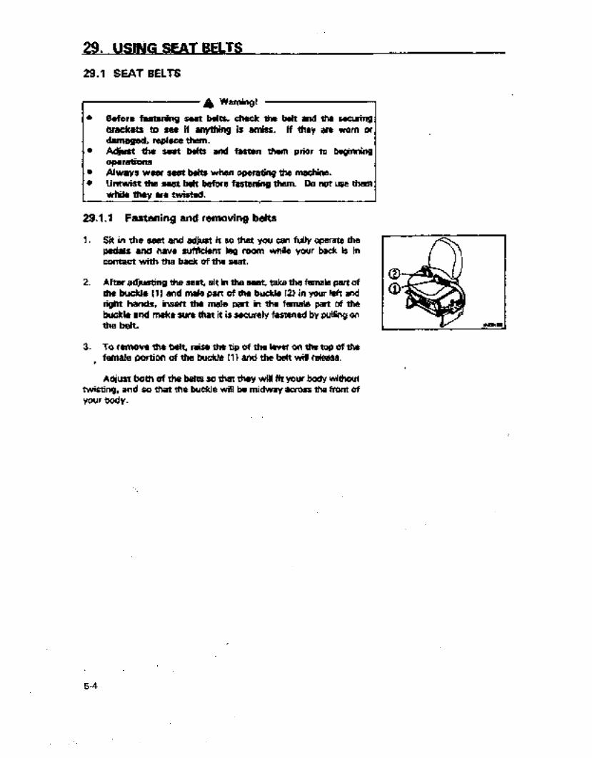
29. USlhiG SEAT BELTS
29.1 SEAT BELTS
A Warning!
l Before faetenfng seat belts. check the belt and the securing brackets to see if anything is amiss. If they are worn or damaged, replete them.
8 Ad&t the seat belts and fasten them prior to beginning operaions
l Always wear Seat beits when operating the machine. 8 Untwist the seat belt before fastening them. Do nat use them
while they are twisted.
29.1.1 Fastening and removing belts
1. Sit in the seat 8nd adjust it so that you can fuIly operate the pedals and have sufficient leg room while your beck is in contact with the back of the seat.
2. Afrer adjusting the seat, sit in the seat, take the female part of the buckle (1) and male part of the buckle (2) in your left and right hands, insert the male part in the female pert of the buckle and make sure that it is securely fastened by pulling on the b&t.
3. To r8rnove the belt, raise the tip of the lever on the top of the f female portion of the buckle (1 I and the. belt will release.
Adjust both of the belts so that they will fit your body without twisting, and so that the buckle will be midway across the front of your body.
5-4
https://tractormanualz.com

29,.. USING SEAT BELTS
29.12 Adjusting the beit length
m Shortening
Pull the free end of the belt on either the sides of the belt.
m Lengthening ’
Pull the belt while holding it at a right angle to either part of the buckle.
Check to make sure that the bolts which fasten the belt hardware to the chassis are not loose. If they are tighten them.
Tightening torque is 2.5 f 0.5 kgm.
Replace the seat belts is they appear to be frayed or damaged or if the hardware is damaged or bent.
“( -%a .
c
5-5
https://tractormanualz.com

30. INFORMATION ON OPTIONAL ATTACHMENTS
30.1 INFORMATION ON OPTIONAL ATTACHMENTS
Name
Narrow bucket (Vertical pin)
Specifications, use
Capacity width 0.16 m3
450 mm
Narrow bucket (Vertical, horizontal pin) Capacity width 0.26 m3
600 mm
Narrow bucket (Vertical, horizontal pin) Capacity width 0.33 m3
700 mm
Standard bucket (Horizontal pin) Capacity width 0.40 m3
833 mm
Heavy duty bucket (Vertical, horizontal pin) Capacity width 0.40 m3
833 mm
Heavy duty bucket (Vertical, horizontal pin) Capacity width 0.45 m3
859 mm
Light duty bucket (Vertical, horizontal pin)
Tracks
Capacity width 0.45 m3
859 mm
Triple track 700 mm width triple track 600 mm width triple track 500 mm width Road liner 500 mm width
Long arm
Cold weather area (B) specifications
Arm length 2,430 mm Maximum excavating depth 5,140 mm
Can start 5 minutes after preheating at temperatures of 30°C
Head guard A device for protecting the operator which
should always be used in job sites where there
is the danger of falling rocks and boulders etc.
l Various others are available such as rear underview mirrors, mono-booms, multi-operation patterns (rotary valve type), cab front guards, automatic linear excavation etc. Seek the assistance of Komatsu of your Komatsu dealer for this.
5-6
https://tractormanualz.com

30. INFORMATION ON OPTIONAL ATTACHMENTS
30.2 ATTACHMENT COMBINATION TABLE
This is a list of the buckets you can attach to the standard arm and the long arm. 0 means that it can be used X indicates that it cannot be used
NOTICE
Be careful because when the long arm is installed, the bucket will hit the body of the machine if it is pulled in as dose to the machine as it can go. It will also hit the undercarriage when excavating diagonally.
Categories of use
General excavation: Light excavation:
Excavating or loading sand, gravel and clay Digging or loading dry, loose soil, sand, and mud
Loading: Loading dry, loose soil and sand
l We recommend the heavy duty bucket which is superior in durability and resistance to wear when excavating or loading compacted soils, or soft rock
Name
Narrow bucket (Vertical pin) 0.16 450 570
Model I
I Standard PC1 28UU Use Arm
OP I For narrow width excavation I 0
Narrow bucket I (Vertical. i 0.26 t 600 i 720 OP I For narrow width excavation I 0 0 horizontal pin) OP
Narrow bucket (Vertical, 0.33 700 820 OP For narrow width excavation 0 0 horizontal pin) OP
Long Arm
0
Standard bucket (Horizontal 0.40 833 953 Standard For general excavation 0 X pin) OP
Heavy duty bucket (Vertical, 0.40 833 953 OP For heavy duty excavation 0 X horizontal pin) OP
Heavy duty bucket (Vertical. 0.45 859 979 - For heavy duty excavation 0 X horizontal pin)
tight duty bucket (Vertical, 0.45 859 979 OP For general excavation 0 X horizontal pin) OP
OP: Indicates option
5-7
https://tractormanualz.com
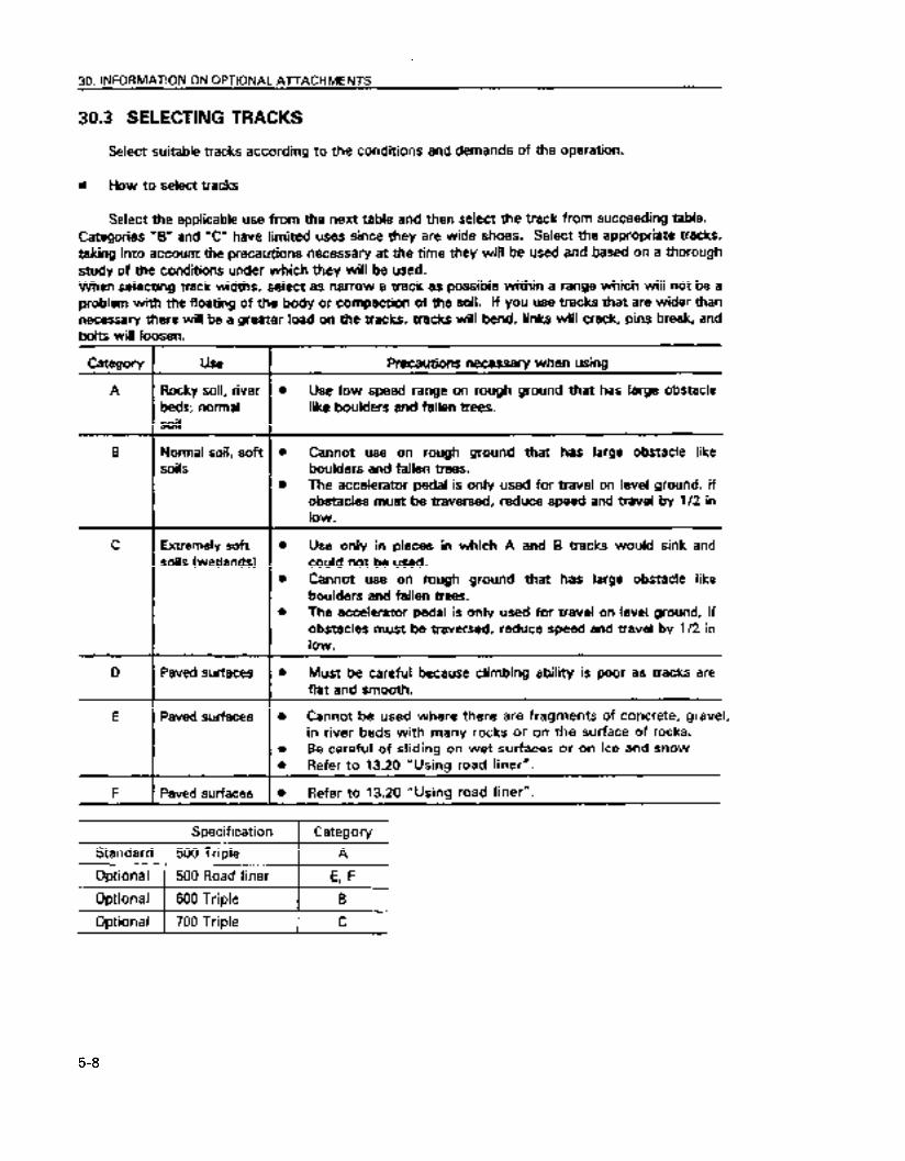
30. INFORMATION ON OPTIONAL A~ACHMENTS
30.3 SELECTING TRACKS
Select suitable tracks according to the conditions and demands of the operation.
g How to select tracks
Select the applicable use from the next table and then select the track from succeeding table. Categories “B” and “C” have limited uses since they are wide shoes. Select the appropriate tracks, taking into account the precautions necessary at the time they will be used and based on a thorough study of the conditions under which they will be used. When selecting track widths, select as narrow a track as possible within a range which will not be a problem with the floating of the body or compaction of the soil. If you use tracks that are wider than necessary there will be a greater load on the tracks, tracks will bend, links will crack, pins break, and bolts will loosen.
Category
A
B
C
I
Use
Rocky soil, river beds; normal soil
Normal soil, soft soils
Extremely soft soils (wetlands)
D I Paved surfaces
E Paved surfaces
I
F Paved surfaces
Precautions necessary when using
0 Use low speed range on rough ground that has large obstacle like boulders and fallen trees.
0 Cannot use on rough ground that has large obstacle like boulders and fallen trees.
0 The accelerator pedal is only used for travel on level ground, if obstacles must be traversed, reduce speed and travel by l/2 in low.
l Use only in places in which A and B tracks would sink and could not be used.
l Cannot use on rough ground that has large obstacle like boulders and fallen trees.
0 The accelerator pedal is only used for travel on level ground, if obstacles must be traversed, reduce speed and travel by l/2 in low.
a Must be careful because climbing ability is poor as tracks are flat and smooth.
0 Cannot be used where there are fragments of concrete, gravel, in river beds with many rocks or on the surface of rocks.
0 Be careful of sliding on wet surfaces or on-ice and snow l Refer to 13.20 “Using road liner”.
l Refer to 13.20 “Using road liner”.
Specification Category
Standard 500 Triple A
Optional 500 Road liner E, F
Optional 1 600 Triple 1 B
Optional ) 700 Triple I -c -
5-8
https://tractormanualz.com

30. INFORMATION ON OPTIONAL All-ACHMENTS
30.4 USING THE AUTOMATIC LEVELING DEVICE
A Warning!
1 I
Automatic operation with the wrong method may lead to unpredictable movement of the arm and boom apparatus and cause a seriqus accident involving injury or death.
30.4.1 Explanation of each device
1. Display
Displays the gradient when automatic leveling is being done. (Displayed in degrees) The way gradient is displayed is as shown in the diagram on the right.
Additional explanation
When the automatic leveling device is set, al three indicator lights will flash.
‘ 5-9
https://tractormanualz.com

30. INFORMATION ON OPTIONAL ATTACHMENTS
2. Automatic leveling device setting switch
Use this when you are going to perform automatic leveling. If you push it once it will turn ON, if you push it again it will then turn off. When it is ON, you can perform automatic leveling by double clicking the knob switch.
3. Bucket position select switch
This is a switch that is used to select a bucket position with respect to the slope that is going to be graded when using the automatic leveling device. 0
0
0
4.
Fiat face:
Blade edge: Automatic:
-Fixes the bucket position with respect to the surface to be excavated. Fixes the bucket position with respect to the arm Before excavation begins, automatically judges from the bucket position whether it is to be flat face or blade edge and proceeds to excavate.
Excavation direction select switch
This is a switch that is used to select the direction to be excavated when using the automatic leveling device. 0 Pull in: Will excavate with the arm pulling in. 0 Pushing out: Will excavate with the arm pushing out 0 Automatic: Before excavation begins, automatically judges
from the position of the arm whether it is to be pulling in or pushing out and proceeds to excavate.
5. Increase /decrease gradient switch
This is a switch to fine tune gradient when automatic leveling is being done. The up arrow indicates increase, the down arrow indicates decrease.
5-10
https://tractormanualz.com

30. INFORMATION ON OPTIONAL ATTACHMENTS
6. Knob,switch (option)
The knob switch on the level control lever for the arm and boom apparatus is used for instantly increasing excavation power and for activating the automatic leveling feature.
How to use the knob switch
1. For increasing excavation power
Push it once and continue pushing (single click). The increase in excavation power will last a maximum of 8.5 seconds.
2. Automatic leveling feature
After pushing it lightly once and then removing the hand push the knob switch again (double click) and continue pushing. This feature will only be activated while the switch is being pushed. Press it the first and second times within an interval of 2 seconds.
5-11
https://tractormanualz.com

30. INFORMATION ON OPTIONAL ATTACHMENTS
30.42 Using the automatic features
A Warning!
If the automatic features are used without proper warming up of the machine, the features will not work properly, so always warm up. Particularly in cold weather, warm up the machine sufficiently.
Automatic operation with the wrong method’ may lead to unpredictable movement of the arm and boom apparatus and cause a serious accident involving injury or death.
The only buckets that can be used are Genuine Komatsu Buckets with optional settings for the PC128UU.
When using the STD buckets (Genuine Komatsu 0.4 M3) data does not need to be rewritten. When using the Genuine Komatsu 0.45 M3 bucket data will need to be rewritten so seek the assistance of Komatsu or your Komatsu dealer for this service.
Do not use the automatic operation when the bucket is reversed.
When the arm is changed, calibration will be necessary just as it would be if the bucket was changed. Seek the assistance of Kometsu or your Komatsu dealer for this service. The device will not operate properly if arms other than those recommended by Komatsu are used.
The automatic features will not operate properly if the standard arm and boom apparatus is replaced by attachments. If you are planning to use attachments other than those specified by Komatsu use them after seeking the assistance of Komatsu or your Komatsu dealer.
Do not remove sensors, install them or take them apart. This will cause faulty operation of the automatic features. Always seek the assistance of Komatsu or your Komatsu dealer for this service.
If you strike the sensors on something or discover that they have been damaged, check the operation of the automatic features. If anything is amiss, seek the assistance of Komatsu or your Komatsu dealer for inspection and repair service.
5-l i
https://tractormanualz.com

30. INFORMATION ON OPTIONAL AlTACHMENTS
7 A Warning!
0 Do not perform any operations that wil immerse the sensors in water. If by some chance the sensors have been immersed check the operation of the automatic stop system.
l if there is a probiem request inspection and repair service from Komatsu or vour Komatsu dealer.
NOTICE
0 If there is an abnormality in the system the controller will perform a self-diagnosis, and display an error code on the monitor panel.
0 Depending on what has gone wrong with the systems, the controikr will not perform a self-diagnosis and you may not be able to manipulate the arm and boom apparatus. After moving the machine to a safe location, ask Komatsu or your Komatsu distributor to check the machine.
0 Before using the automatic features, always perform the checks before starting and after starting the machine. In cold weather use the features after warm up operation. If the amount of hydraulic fluid is low, the features will not operate properly.
n Before operating the feature
a Double click
When using the automatic features, many of them use the knob switch on the left control fever ‘for the arm and boom apparatus. To use the automatic feature “double click” this switch.
Double dicking means after pushing it lightly once and then removing the hand push the knob switch again (double click) and continue pushing. This feature will only be activated while the switch is being pushed. Press it the first and second times within an interval of 2 seconds.
5-13
https://tractormanualz.com

30. INFORMATION ON OPTIONAL ATTACHMENTS
I Automatic operation
Linear excavation with the bucket blade edge or flat face with the desired gradient can be done and the following finishing operations can be done.
l Finishing of surfaces on which roads will be paved. 0 Finishing of ditch bottom surface l Raking operations 0 Surface grading operations 0 Spreading and filling in operations
5-14
https://tractormanualz.com

30. INFORMATION ON OPTIONAL ATTACHMENTS
1.
2.
3.
4.
5.
Move the’ bucket to place the bucket blade angle at the gradient that you want to finish.
Push the automatic leveling setting switch (1 I. The monitor display will change from displaying depth and will display the desired gradient (in degrees) and the lights for depth, height and offset will all three flash and a buzzer will sound 2 times at the same time.
You can modify the desired gradient with the gradient increase/ decrease switch (4).
Place the fuel adjustment control lever in the full (MAX) position.
After lightly pressing the knob switch on the left control lever once and then releasing it and pressing it again and continuing to press (double clicking), a buzzer will sound twice and leveling will begin. If you release piessure on the knob switch, leveling will cease.
5-l 5
https://tractormanualz.com
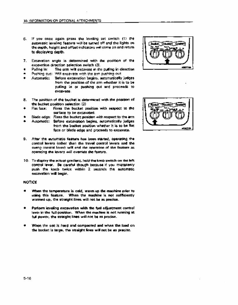
30. INFORMATION ON OPTIONAL ATTACHMENTS
6.
7.
l
l
0
9.
10.
If you once again press the leveling set switch (1) the automatic leveling feature will be turned off and the lights on the depth, height and offset indicators will come on and return to displaying depth.
Excavation angle. is determined with the position of the excavation direction selection switch (3). Pulling in: The arm will excavate in the pulling in direction Pushing out: Will excavate with the arm pushing out Automatic: Before excavation begins, automatically judges
from the position of the arm whether it is to be pulling in or pushing out and proceeds to excavate.
The position of the bucket is determined with the position of the bucket position selection (21 flat face:
Blade edge: Automatic:
Fixes the bucket position with respect to the surface to be excavated. Fixes the bucket position with respect to the arm Before excavation begins, automatically judges from the bucket position whether it is to be flat face or blade edge and proceeds to excavate.
After the automatic feature has been started, operating the control levers (other than the travel control levers and the swing control lever) will end the operation of the feature as operating the levers will override the feature.
To display the actual gradient, hold the knob switch on the left control lever. Be careful though because if you mistakenly push the knob twice within 2 seconds the automatic excavation will begin.
NOTICE
When the temperature is cold, warm up the machine prior to using this feature. When the machine is not sufficientty warmed up, the straight lines will not be as precise.
Perform leveling excavation with the fuel adjustment control lever in the full position. When the machine is not running at full power, the straight lines will not be as precise.
When the soil is hard and compacted and when the load on the bucket is large, the straight lines will not be as precise.
5-16
https://tractormanualz.com
30. INFORMATION ON OPTIONAL A-lTACHMENTS
l
i
l
The feature is set so that it will be sufficiently precise when there is a load ( when the bucket is pushing with its bottom)
There is an inclination gauge installed on the machine which compensates for the inclination of the machine fore and aft. The tolerance value is an inclination of the machine at f 17 degrees. If this is exceeded the gradient will not be as precise.
The inclination gauge only measures the inclination fore and aft so that if the machine is leaning to the side there will an error in the gradient set.
Put the right and left control levers for the arm and boom apparatus in neutral when double clicking the knob switch to start linear excavation. if these levers are not in the neutral position, linear excavatfon will not begin.
When excavating with the bottom of the bucket, because of the position. the bucket will reach the end of the stroke on its cylinder when the arm is only in mid-stroke of its cylinder so that excavation will cease.
in operations in which lifting and lowering is nearly vertical, the automatically chosen direction of excavation will sometimes be the direction opposite from what the operator intends. If this happens, fix the setting for direction of excavation.
Automatic deceleration will not operate while automatic leveling is operating.
if the ignition switch is turned OFF, and the display goes off. the memory for the gradient set will be deared.
Depth, height and offset modes cannot be set at the same time.
Operation will not be as precise when the feature is operated automatically near the end of the stroke of the arm cylinder. Avoid operating near the end of the stroke.
5-17
https://tractormanualz.com

30. INFORMATION ON OPTIONAL ATTACHMENTS
30.4.3 Troubleshooting the automatic leveling system
When error codes other than for the standard vehicle (those of the 4 systems) are displayed on the display of the monitor panel, refer to the table below.
Error code Problem phenomenon Chief cause I Corrective measure
1q Defective bucket
Cannot excavate automatically
potentiometer Normal operations can be
Defective inclination gauge performed but should be
Defective automatic checked immediately
excavation solenoid
Defective arm dump EPC After moving the machine
82 Cannot dump arm
84 I
88 I
Al
i
Cannot excavate automatically
A2
solenoid
I
to a safe place with the override switch, have it checked immediately
Defective bucket excavation EPC solenoid
Defective bucket excavation EPC solenoid
Defective boom H pressure sensor Normal operations can be
performed but should be Defective boom B Pressure checked immediately sensor
A4 Defective boom H pressure sensor
A8 Defective boom B pressure sensor
5-18
https://tractormanualz.com

PC128UU1 HYDRAULIC EXCAVATOR
Form No. SEAM023300
O1998 wf~u
All Rights Reserved
lo-98 (01-l) IO-98 (01-7)
https://tractormanualz.com

Komatsu America international Company 440 North Fairwav Drive I 1 Vernon Hills, IL 66061-8112 U.S.A. Attn: Technical Publications PROPOSAL FOR MANUAL REVlslON Fax No. (847) 970-4186
PFMRl 081696
FOR INTERNAL USE ONLY -- No. PMR
2 NAME OF COMPANY:
:
: S DEPARTMENT:
E R NAME:
LOCATION:
PHONE NO:
DATE:
MANUAL NAME:
MANUAL NO:
MACHINE MODEL: S/N IF APPLICABLE:
PAGE NO:
PROBLEM:
Attach photo or sketch. If more space is needed, use another sheet.
1 FOR INTERNAL USE ONLY
CORRECTIVE ACTION:
https://tractormanualz.com

KOMR’tbU Komatsu America International Company
https://tractormanualz.com