Hydraulic direct drive system Hägglunds Torque Arm Drive ... · 2 Hydraulic direct drive system |...
20
Hydraulic direct drive system Hägglunds Torque Arm Drive System – TADS RA 15426, edition: 07.2017, Bosch Rexroth Corporation Features Designed for apron feeders, belt feeders, belt convey- ors, and infeed conveyors Small footprint Self-contained drive system Easy installation Maintenance friendly design Spline or Shrink Disc Motor Hägglunds advanced control system No foundation needed Unlimited starts and stops Direct drive Overview of contents Features 1 General info 1 Ordering code 2 Product description 4 Function Hägglunds TADS 5 Technical data 8 Standard overall dimensions 9 Mounting 10 Main components 12 Environment options 18 Accessories 19 Additional documents 20 General info Torque: Up to 203,000 ft-lbs Speed: Up to 60 rpm Max. operating pressure: 5076 psi Power: Up to 100 hp Ambient temperature: –40 °F to 105 °F RA 15426 Edition: 07.2017
Transcript of Hydraulic direct drive system Hägglunds Torque Arm Drive ... · 2 Hydraulic direct drive system |...

Hydraulic direct drive system Hägglunds Torque Arm Drive System – TADS
RA 15426, edition: 07.2017, Bosch Rexroth Corporation
Features � Designed for apron feeders, belt feeders, belt convey-
ors, and infeed conveyors � Small footprint � Self-contained drive system � Easy installation � Maintenance friendly design � Spline or Shrink Disc Motor � Hägglunds advanced control system � No foundation needed � Unlimited starts and stops � Direct drive
Overview of contentsFeatures 1General info 1Ordering code 2Product description 4Function Hägglunds TADS 5Technical data 8Standard overall dimensions 9Mounting 10Main components 12Environment options 18Accessories 19Additional documents 20
General info � Torque: Up to 203,000 ft-lbs � Speed: Up to 60 rpm � Max. operating pressure: 5076 psi � Power: Up to 100 hp � Ambient temperature: –40 °F to 105 °F
RA 15426Edition: 07.2017

2 Hydraulic direct drive system | Hägglunds Torque Arm Drive System – TADSOrdering code
Bosch Rexroth Corporation, RA 15426, edition: 07.2017
Ordering code
Hydraulic drive power units01 TADS
Hydraulic Motor02 CA 50 CA 50
CA 70 CA 70CA 100 CA 100CA 210 CA 210CB 280 CB 280CB 400 CB 400CB 560 CB 560CB 840 CB 840
Pump Capacity03 28cc 028
40cc 04071cc 071125cc 125
Electric Motor Horsepower04 15HP 015
20HP 02025HP 02540HP 04050HP 05060HP 06075HP 075100HP 100
Controls05 No Controls, Junction Box Only 0
Driver Card 1Spider Control 2Spider Control w/ Profibus 3Spider Control w/ Modbus RTU 4Spider Control w/ Modbus TCP 5Spider Control w/ ControlNet 6Spider Control w/ DeviceNet 7Spider Control w/ Ethernet IP 8
NEMA Classification06 NEMA 4 0
NEMA 4X 1
Pressure Gauges07 Yes 0
No 1
Motor Flushing08 Yes 0
No 1
Filter Type09 Single 0
Duplex 1
01 02 03 04 05 06 07 08 09 10 11 12 13 14 15 16 17 18 19 20
TADS – – – – – – – – – – /

Hägglunds Torque Arm Drive System – TADS | Hydraulic direct drive systemOrdering code
3
RA 15426, edition: 07.2017, Bosch Rexroth Corporation
01 02 03 04 05 06 07 08 09 10 11 12 13 14 15 16 17 18 19 20
TADS – – – – – – – – – – /
Torque Arm Orientation (Viewed from motor port side)10 3 O'Clock 3
9 O'Clock 9
Hydraulic Motor Direction of Rotation (Viewed from shaft side of hydraulic motor)11 Clockwise 0
Counterclockwise 1
Type of Command Signal12 Uni-directional 0
Uni-directional with Jog Reverse 1Bi-directional 2
Oil Heater13 None 0
375W - Recommended when ambient temp is below 40 °F (4 °C) – minimum temp 20 °F 1Cold Weather Package #1 - Minimum Temp = –4 °F (–20 °C) 2Cold Weather Package #2 - Minimum Temp = –22 °F (–30 °C) 3Cold Weather Package #3 - Minimum Temp = –40 °F (–40 °C) 4
Heat Exchanger14 Air / Oil Cooler (380VAC) 0
Air / Oil Cooler (460VAC) 1Air / Oil Cooler (575VAC) 2Water / Oil Cooler 3
Control Box Voltage15 No Voltage 0
24 VDC A120 VAC B240 VAC C
Hydraulic Oil16 Filled with No Oil 0
Filled with ISO 68 Synthetic Oil 1Filled with ISO 100 Synthetic Oil 2Filled with ISO 68 Mineral Oil 3Filled with ISO 100 Mineral Oil 4
Encoder Type17 No Encoder 0
SPDC CA (1856PPR) 1SPDC CB (1856PPR) 2SPDC CA (1856PPR) with F/A Converter - Driver Card Only 3SPDC CB (1856PPR) with F/A Converter - Driver Card Only 4
Unit Type18 Standard S
Non-Standard N
Electric Motor Voltage19 380 VAC 380
460 VAC 460575 VAC 575
Electric Motor Frequency20 50 Hz 50
60 Hz 60

4 Hydraulic direct drive system | Hägglunds Torque Arm Drive System – TADSProduct description
Bosch Rexroth Corporation, RA 15426, edition: 07.2017
Product description
The Hägglunds TADS hydraulic direct drive system is a compact self-contained drive with high reliability and long service life. The TADS delivers high torque throughout speed range with infinite start, stop, and reverse, which will not damage the system. The TADS is rugged and reliable, designed for outdoor use in all weather conditions, used primarily in apron feeders, belt feeders, belt conveyors and infeed conveyors. While designed for the above demanding applications the uses for a TADS are numerous.
The Hägglunds TADS hydraulic direct drive system is an infinitely variable ratio drive, a gear box is not required to adjust ratio affecting speed. This allows for flexibility in speed range to adjust process capacity without varying electric motor frequency or adjusting gear ratios. The sys-tem is capable of producing any speed within its specified range. The design is compact and open, affording easy access and maintenance. Installation is easy and comes with either internal splines or hollow shaft with a compres-sion coupling that mounts directly to the machine’s drive shaft.
Hägglunds TADS hydraulic direct drive system includes the following standard features:
� High pressure transducer which allows for monitoring maximum system pressure to ensure no damage to the equipment.
� Charge pressure transducer ensures hydraulic motor and pump internal parts are fully engaged and ready to produce torque upon demand.
� Torque arm with pivot attachment which can handle load in tension or compression.
� Oil level indicator with local temperature indication located on the front of the reservoir for ease of viewing
� Reservoir drain valve. � 100 liter stainless steel reservoir to ensure no corrosion
in the reservoir that could lead to oil contamination. � Hägglunds drive systems filter all returning oil to keep
the reservoir clean. � Filter air breather. � Two position level switch that will send a warning signal
when oil level falls below pre-determined value, then an alarm which will shut the drive system down so no permanent damage will occur.
� Temperature transmitter monitors reservoir temperature to ensure minimum temperature for startup and maxi-mum temperature for interlock to protect equipment
� Quick fill connection located on the inlet side of the pump/motor case drain filter that allows the addition of oil straight from a drum into the system. The oil is then immediately filtered before entering the reservoir.
� Reverse drive speed is able to be limited mechanically, enabling increased protection from over-speed or unin-tended directional operation.
� Electric motors 15-75 HP have a max altitude of 9842 fasl, electric motors 100 HP have a max altitude of 8202 fasl. Electric motors with higher elevations are available upon request.
� Classified environments are available upon request.
The Hagglunds TADS hydraulic direct drive system offers three control configurations.
� Hagglunds Advanced Control System (Spider) The Spider allows complete control of the TADS with minimal customer connections. A junction box will be located on the TADS and a control box will be remote mounted.
� Driver Card Control The driver card allows control of pump stroke only from customer control system and has connections for customer monitoring. The driver card control box is located on the TADS.
� No Controls The TADS will be completely controlled and monitored from the customer control system. A junction box for customer connections is located on the TADS.

Hägglunds Torque Arm Drive System – TADS | Hydraulic direct drive systemFunction Hägglunds TADS
5
RA 15426, edition: 07.2017, Bosch Rexroth Corporation
Function Hägglunds TADS
The Hägglunds TADS hydraulic direct drive system features an asynchronous electric motor driving a variable stroke axial piston pump. Hydraulic motor speed is controlled by varying the analog signal to the proportional solenoid stroker on the hydraulic pump, which sets the swash plate angle and therefore piston stroke and resultant flow to the hydraulic motor. An optional speed encoder can be supplied to provide full closed loop speed feedback and control. The control system utilizes the speed encoder signal to increase or de- crease the flow to the hydraulic motor to maintain speed to accommodate for changes in customer process.
The Hägglunds advanced control system, Spider, is a microcontroller-based system, configurable to suit different application needs. The Spider has a large variety of configu-rable functions to simplify the control and health monitor-ing of the TADS.
The Spider is pre-programmed and easy to configure and contains functions such as:
� Variable speed control � Speed feedback � Power limitation � Industrial fieldbus communication � Analog and digital signal monitoring � Pressure control (torque control)
Also application specific functions such as: � Friction control � Shredder control � Synchronized control
For detailed functionality and configuration, see data sheet for Hägglunds Spider Control System EN777. The TADS drive system can be delivered without control system if required. All electrical wiring for sensors and pump control will be wired to a junction box assembled on the drive system.
Driver card for pump can be assembled as an alternative in the junction box.
Monitoring of the drive unit sensors must be handled exter-nally according to the Monitoring logic diagram on page 7.
Ambient Temperature
Upper limitA standard drive system has an upper ambient temperature limit of 105 °F.
Lower limitA standard drive system has a lower ambient temperature limit of –40 °F, when proper cold weather package is selected from model code
6 Hydraulic direct drive system | Hägglunds Torque Arm Drive System – TADSFunction Hägglunds TADS
Bosch Rexroth Corporation, RA 15426, edition: 07.2017
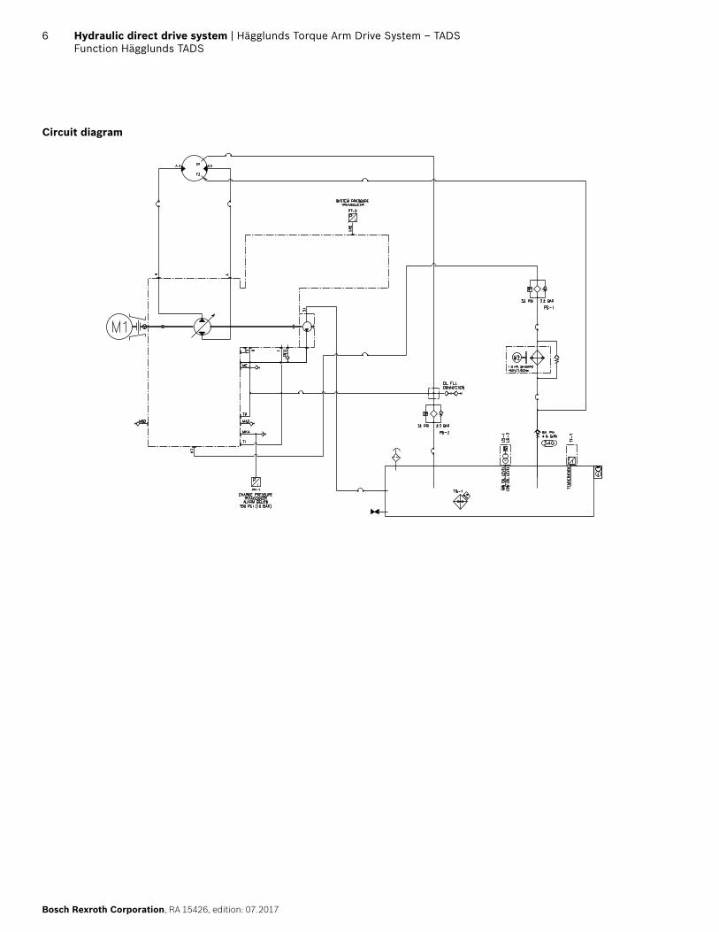
Circuit diagram

Hägglunds Torque Arm Drive System – TADS | Hydraulic direct drive systemFunction Hägglunds TADS
7
RA 15426, edition: 07.2017, Bosch Rexroth Corporation
Monitoring logic diagram
>150 psi
Max. oil temp >140°F
Min. oil temp <32°F
Interlock temp >140°F
Cooling temp >105°F
Heating temp <65°F
High oil temp >131°F

8 Hydraulic direct drive system | Hägglunds Torque Arm Drive System – TADSTechnical data
Bosch Rexroth Corporation, RA 15426, edition: 07.2017
Technical data
TADS Size Max. Installed Power (hp)
Speed Range* (rev/min)
Specific Torque (TS) (lbf-ft/1000 psi)
Max. Torque** (lbf-ft)
TADS-050 75 0 – 60 2543 12092
TADS-070 75 0 – 43 3560 16928
TADS-100 75 0 – 30 5085 24179
TADS-140 75 0 – 22 7119 33850
TADS-210 75 0 – 14 10678 50774
TADS-280 100 0 – 11 14200 67521
TADS-400 100 0 – 7.5 20300 96527
TADS-560 100 0 – 5 28500 135518
TADS-840 100 0 – 3.5 42700 203039
* For speeds above this range please contact Bosch Rexroth at [email protected] ** Calculated as T = Ts x (5000 - 245)/1000
Larger sizes available on request.

Hägglunds Torque Arm Drive System – TADS | Hydraulic direct drive systemStandard overall dimensions
9
RA 15426, edition: 07.2017, Bosch Rexroth Corporation
Standard overall dimensions
TADS Size A (in)
B1* (in)
B2* (in)
C (in)
D** (in)
E (in)
Shrink Disc Shaft Ø (in)
Splines Ø*** (mm)
Weight (lbs)
TADS-050 63 30.75 33.75 16.0 45.5 12.00 4.724 N120x5x30x22x9H 3000
TADS-070 63 30.75 33.75 16.0 45.5 12.00 4.724 N120x5x30x22x9H 3100
TADS-100 63 34.25 37.75 16.0 45.5 13.00 5.512 N140x5x30x26x9H 3200
TADS-140 63 34.25 37.75 16.0 46.5 14.00 5.512 N140x5x30x26x9H 3400
TADS-210 63 35.00 40.00 16.0 46.5 14.00 6.299 N150x5x30x28x9H 3600
TADS-280 70 34.00 37.75 24.5 50.5 19.25 7.087 N200x5x30x38x9H 4200
TADS-400 70 34.00 38.25 24.5 50.5 19.25 7.874 N200x5x30x38x9H 4900
TADS-560 70 40.50 43.75 24.5 53.0 21.75 10.236 N260x5x30x50x9H 5100
TADS-840 70 40.50 43.75 24.5 53.0 21.75 10.236 N260x5x30x50x9H 6100
* Dimension may very based on e-motor size
** Dimension may very based on cooler size*** Shaft adapters available upon request
Shrink disc version Spline version

10 Hydraulic direct drive system | Hägglunds Torque Arm Drive System – TADSMounting
Bosch Rexroth Corporation, RA 15426, edition: 07.2017
Shrink Disc
Normally-loaded shaftIn drives with only one direction of rotation where the stresses in the shaft are moderate, the shaft can be plain, see Figure 1, and Tables 1 and 2.
A D
F
G
30°
.24±.02
E
MAX Ra 125
c Figure 1
Design of driven shaft end on heavily-loaded shaftWhere the driven shaft is heavily loaded and is subject to high stresses, for example on changes in the direction of rotation, it is recommended that the driven shaft should have a stress relieving groove; see Figure 2, and Tables 1 and 2.
A D
E
.24±.02
30°
F
G
B±.02 R1.97
C
MAX Ra 125
c Figure 2
Unidirectional drives
Steel with yield strength Rel = 43,500 psi
Bidirectional drives
Steel with yield strength Rel = 65,250 psi
Table 1. Valid for couplings (Figures 1 and 2)Dim (in.) CA50/70 CA100/140 CA210 CB280 CB400 CB560/840
A 4.7244 +0/ -0.00098 5.5118 +0/
-0.00098 6.2992 +0/ -0.00098 7.0866 -0.00055/
-0.00213 7.8740 -0.00059/ -0.00240 10.2362 -0.00067/
-0.00272
B 2.81 3.33 4.13 4.17 4.61 6.02
C 4.57 5.24 6.02 6.85 7.64 10
Table 2. Alternative thread (Figures 1 and 2)Dim (in.) CA50/70 CA100/140 CA210 CB280 CB400 CB560/840D M20 M20 M20 M20 M20 M20
E >0.67 >0.67 >0.67 >0.67 >0.67 >0.67
F 0.98 0.98 0.98 0.98 0.98 0.98
G 1.97 1.97 1.97 1.97 1.97 1.97
NOTICE! The dimensions are valid for 68 °F.
Mounting

Hägglunds Torque Arm Drive System – TADS | Hydraulic direct drive systemMounting
11
RA 15426, edition: 07.2017, Bosch Rexroth Corporation
Spline
To avoid wear in the splines, the installation must be within the specified tolerances in table 3.3. For production of the shaft, see 278 2231, 278 5023, 278 2235, 278 5025 and 278 2238.
Unidirectional drives
Steel with yield strength Relmin = 63,250 psi
Bidirectional drives
Steel with yield strength Relmin = 101,500 psi
Table 3. Motor CA50/70 CA100/140 CA210 CB280/400 CB560/840
Tooth profile and bottom Form DIN5480 DIN5480 DIN5480 DIN5480 DIN5480
Tolerance 8f 8f 8f 8f 8f
Guide BACK BACK BACK BACK BACK
Pressure angle 30° 30° 30° 30° 30°
Module 5 5 5 5 5
Number of teeth 22 26 28 38 50
Pitch diameter Ø110 Ø130 Ø140 Ø190 Ø250
Minor diameter Ø108 +1/ -1.62 Ø128 +1/
-1.62 Ø138 +1/ -1.62 Ø188 +0/
-1.201 Ø248 +0/ -1.201
Major diameter Ø119 +0/ -0.220 Ø139 +0/
-0.250 Ø149 +0/ -0.250 Ø199 +0/
-0.290 Ø259 +0/ -0.320
Measure over pins 129.781 -0.083/ -0.147 149.908 -0.085/
-0.150 159.961 -0.085/ -0.150 210.158 -0.088/
-0.157 270.307 -0.103/ -0.181
Diameter of measuring pins Ø10 Ø10 Ø10 Ø10 Ø10
Addendum modification X M +2.25 +2.25 +2.25 +2.25 +2.25
Reaction Point
0°±5°
Alternate position
NOTICE! The togglebearing must be dismounted during welding
X
3/8
X = ± 0.079 misalignment in installationX ≤ ± 0.59 movement when in use
Steel:ASTM A572 GR50protected againstcorrosion, afterWelding
c Figure 3. Mounting of pivoted attachment

12 Hydraulic direct drive system | Hägglunds Torque Arm Drive System – TADSMain components
Bosch Rexroth Corporation, RA 15426, edition: 07.2017
Main Pump
Features � Variable displacement axial piston pump of swashplate
design for hydrostatic closed circuit transmissions � Flow is proportional to speed and displacement and is
infinitely variable through adjustment of the swivel angle � Output flow increases with swivel angle from 0 to its
maximum value � Swivelling the pump over center smoothly changes the
direction of flow � The pump is equipped with two pressure relief valves
on the high pressure ports to protect the hydrostatic transmission (pump and motor) from overloads
� One common pump for charge and EP displacement control
� Compact overall design � Low noise level � Long service life � High efficiency
Technical data A4VG28 and SP40-125Size 28 40 71 125Displacement
Variable pump Vg max cm3 28 40 71 125
Auxiliary pump Vg H cm3 28 20 25 38
Speed
max. speed nmax rpm 1800 1800 1800 1800
min. speed nmin rpm 1500 1500 1500 1500
Flow
at nE=1800 rpm gpm 13.2 18.8 33.4 58.8
at nE=1500 rpm gpm 10.9 15.6 27.8 48.9
Power, max. at (Dp=350 bar)
at nE=1800 rpm hp 50 60 75 100
at nE=1500 rpm hp 40 50 50 60
Case volume gal 0.2 0.5 0.7 1.3
Operating pressure rangeDepending on the behavior of the transmitted hydraulic energy in the system, charge pressure fluctuations can occur. In order to prevent damage to the system, charge pressure protection, which monitors the static charge pressure portion is necessary. Port MK4 is suitable to monitor the charge pressure. It is recommended to regu-larly check the charge pressure for the permissible max. and min. spikes with suitable measuring equipment.
Electric Motor
FunctionThe electric motor is a totally enclosed, fan cooled TEFC squirrel-cage, 4-pole 3-phase motor. The electric motors used as standard in the drive unit are manufactured by WEG. It is possible to select other customer supplied brands of electric motors as long as the limitations in elec-tric motor dimensions and maximum weight are held.
Output power 15-100 hp
Voltage frequency380 V 50 Hz 440 V 60 Hz400 V 50 Hz 460 V 60 Hz415 V 50 Hz 480 V 60 Hz
Technical dataOperating Duty: S1Method of Mounting: Vertical, F1 conduit boxDegree of Protection: IP55Cooling Form: FanInsulation Class: FGreasing: Zerk styleHeater Elements: 120 V 50/60 HzPainting: ISO12944 “C2”Sound press. Level Lp: ≤ 70 dB(A)
StandardsStandard: NEMA MG1Effiecency Class: Premium efficiency (IE3)
Main components
Hägglunds Torque Arm Drive System – TADS | Hydraulic direct drive systemMain components
13
RA 15426, edition: 07.2017, Bosch Rexroth Corporation
Control and Adjustment Devices
EP – Electro-hydraulic control with proportional solenoidThe EP control adjusts the pump displacement proportional to the solenoid current. The pump displacement is there-fore infinitely variable. One proportional solenoid is assigned to each direction of flow.
Operating voltage: 24 VNominal current: 800 mACurrent range 210...740 mANominal resistance at 68 °F: 19 Ω
Mounted charge pressure and control valvesHigh pressure relief valvesTwo pilot operated relief valves.The valves prevent pump damage from excessive pressure levels. Each pressure side has its own relief valve, which is vented to the low pressure side of the loop.
Charge pressure relief valve � The charge pressure relief valve is direct operated � T1 needs external drain � Setting range Pc: 174-305 psi � Standard setting: 218 psi
Control pressure relief valve � Control pressure relief valve is direct operated with
unloading function. � Setting pressure range: 435-653 psi � Normal setting range: 508-610 psi depending on
pump size
Pressure Gauges
Optional pressure gauges will be located in front of and below the electric motor. It will consist of 4 gauges to show charge, control, pump main pressure A port, and pump main pressure B port. Option also comes with nee-dle valves to shut off pressure to gauge.
Flushing
Flushing is used to cool the hydraulic motor depending on need due to the environmental conditions in which the drive system will be operating.
Cold flushing is done by a check valve directing part of the cooled oil from the oil cooler to the connection port of the motor and back to the tank via the drain line.
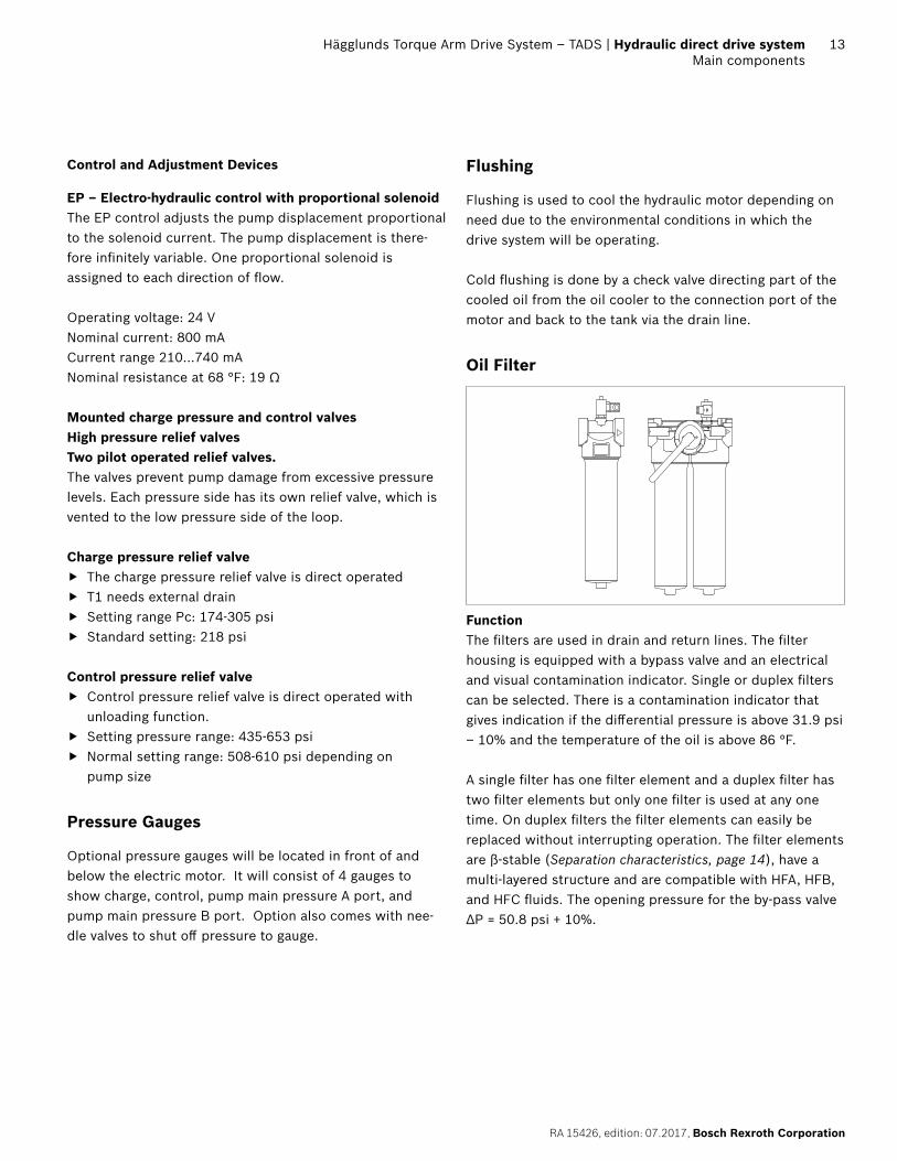
Oil Filter
FunctionThe filters are used in drain and return lines. The filter housing is equipped with a bypass valve and an electrical and visual contamination indicator. Single or duplex filters can be selected. There is a contamination indicator that gives indication if the differential pressure is above 31.9 psi – 10% and the temperature of the oil is above 86 °F.
A single filter has one filter element and a duplex filter has two filter elements but only one filter is used at any one time. On duplex filters the filter elements can easily be replaced without interrupting operation. The filter elements are β-stable (Separation characteristics, page 14), have a multi-layered structure and are compatible with HFA, HFB, and HFC fluids. The opening pressure for the by-pass valve ΔP = 50.8 psi + 10%.

14 Hydraulic direct drive system | Hägglunds Torque Arm Drive System – TADSMain components
Bosch Rexroth Corporation, RA 15426, edition: 07.2017
Standards – filtersThe filter elements are manufactured and tested in accor-dance with the following international standards:
Item StandardVerification of collapse/burst resistance ISO 2941Determination of fabrication integrity ISO 2942Verification of material compatibility with hydraulic fluids
ISO 2943
Verification of flow fatigue characteristics ISO 3724Evaluation of pressure drop versus flow ISO 3968.2Test of end cap load ISO 3723Test of filter performance ISO 4572
Mechanical data
Material, filtersPart MaterialFilter complete:
Filter head Aluminum alloy
Filter bowl Aluminum
Seals Nitrile rubber
Low pressure type bypass Δp
360 psi
50 psi + 10%
Type Single
Duplex
Max flow 66 gpm
106 gpm
160 gpm
Filter element:
Filtration grade 10 μm (standard)
3 μm (optional)
Filter Inorganic glass fibre material
End shields Tin plated
Inside tube Tin plated
Filter switch: Filter switch See section: ”Clogging Indicator”
Separation characteristicsThe β-ratio for the particle size 10 (μm) fullfills ISO 4572 (β10 ≥ 75).
β-ratio determined by multi-pass test
β-ra
tioParticle size in μm
1000
100
10
10 2 4 6 8 10 12 14 16
Clogging Indicator – Oil Filter
FunctionA contamination indicator is mounted in the oil filter hou-sing to indicate when the filter element must be changed. Both a visual and an electric indication are obtained. When the level of contamination in the filter element is increased, the pressure drop over the filter will increase. Indication takes place at a differential pressure across the filter of 32 psi for return and drain filters.
The visual indicator is reset automatically. The electrical indication is internally interlocked by a themo switch below 86 °F rising temperature to avoid indication due to high viscosity. The interlock is activated at 68 °F falling temp.
Protection classProtection class IP 65 acc. to IEC 529 / DIN 40050

Hägglunds Torque Arm Drive System – TADS | Hydraulic direct drive systemMain components
15
RA 15426, edition: 07.2017, Bosch Rexroth Corporation
Mechanical data
Material Clogging IndicatorPart MaterialLower section Aluminum alloy, SteelUpper section PolyamidSeals Nitrile rubber
Clogging IndicatorMax. operating pressure 6000 psiTemperature range –40 °F...212 °FProtection class IP65
c Hydraulic symbol (oil filter with indicator)
Electrical data
Clogging IndicatorSwitch type normally closedSwitching voltage 24 VDC / 250 VACMax. making capacity at resistive load
20 VA/20 W
Cold start suppression 86 °F, rising68 °F, falling
Min. switching current 1 mA
Electrical connectionsConfiguration of plug acc. to DIN 43650 / ISO 4400Cable gland: Pg 11Cable diameter: ⌀ 6-10 mm
c Electrical symbol
Torque Arm Orientation
Viewed from motor port side
Oil Heater
Mechanical DataElement Steel SheathProbe Length 9”
Electrical DataSupply Voltage V 120VAC or 240VAC Single PhaseOutput W 375 WThermostat Integral SPST Set at 65 °F
Cold Weather Package 1In addition to an oil heater suction line heat tracing will be used.
Mechanical DataTemperature Range –40 °F…150 °F
Electrical DataSupply Voltage V 120VAC or 240VACThermostat Self-regulatingOutput Power W 8 Watts/ft
Cold Weather Package 2In addition to an oil heater and suction line heat tracing a heater in the control box will be provided if a driver card is selected.
Cold Weather Package 3In addition to an oil heater, suction line heat tracing, and control box heater (if driver card is selected) wire and conduit will be supplied to comply with a low ambient of –40 °F.

16 Hydraulic direct drive system | Hägglunds Torque Arm Drive System – TADSMain components
Bosch Rexroth Corporation, RA 15426, edition: 07.2017
Air Cooler
Function � The air-oil cooler consists of a fan driven by an electric
motor, blowing air through the cooler matrix � The cooling matrix is bar and plated brazed aluminum � All systems have a 65psi by-pass function to limit the oil
pressure in the cooler � The electric motor is asynchronous.
Oil
The TADS can either be ordered as filled with mineral oil, filled with synthetic oil, or not filled.1) In the case of the mineral oil fill option, it can either be delivered filled with Shell Tellus S3 M 68 (ISO VG 68) or Shell Tellus S3 M 100 (ISO VG 100). In the case of synthetic oil fill, it can either be delivered filled with Mobil SHC 526 (ISO VG 68) or Mobil SHC 527 (ISO VG 100).
1) The four available oil fill options do not represent an exhaustive list of what fluids may be used in a TADS. See document RE15414 – Hydraulic fluid quick reference, document RE15302-WA/10.2015 – CB Compact Installation & Maintenance Manual, or document RE15305-WA/10.2015 – CA Compact Installation & Maintenance Manual for details on fluid selection guidelines.
Encoder
The Hägglunds SPDC encoder features a slim fully inte-grated design with a magnetic sensor. This provides a non-contact wear free sensing system.
Mechanical specification, speed sensorAxial tolerance ± 2 mm (between sensor and
magnetic stripRadial tolerance 1 mm nominal 0.1 and 2.0 mm
(air gap)Protection class IP67 acc. to DIN EN 60529Operating temperature –40 °F…+176 °FVibration ≤ 100 m/s2, sine 50 Hz – 2 kHz
DIN EN 60068 2-6Shock ≤ 1000 m/s2, half sine 11 ms DIN
EN 60068 2-7
Electrical specification, speed sensorSupply voltage +Ub + 24 VDC (10–30 VDC)
Current consumption at no load
≤ 30 mA
Output voltage low 0…2 Vhigh Ub–2 V
Outputs Short circuit protected HTLCable length max 200 m at 50 kHzEMC approval Immunity DIN EN 61000-6-2
Emission DIN EN 61000-6-3
Specification, pin outPin 3 Signal Color (optional cable)1 0 V White2 +Ub Brown3 A+ Green4 A– Yellow5 B+ Gray6 B– Pink7 — Blue8 — Red
When driver card option is selected an F/A converter will be provided in the control box mounted on the TADS drive system. The F/A converter converts a single puls train to a 4-20mA output signal.
Technical data – F/A converterSupply voltage 24 V (12–50 V)Power consumption 3 WOperating temperature –4 °F…+176 °FHumidity 0–90 % RH, non-condensingTemperature coefficient
< 0.01 % / °F
Accuracy better than 0.3 %Resolution 0.1 %Mounting NS35 DIN railSize w45 x d70 x h117
Electrical connections – F/A converterPulse input: – Input high – Input low
Vin > 15 V Vin < 6 V
4– 20 mA Max. output load 500 ΩEMC approval EN 50081-1, EN 50082-2Safety EN 60730

Hägglunds Torque Arm Drive System – TADS | Hydraulic direct drive systemMain components
17
RA 15426, edition: 07.2017, Bosch Rexroth Corporation
Air Breather
The air breathing of the tank is via an air filter element to prevent contamination of the oil by particles in the air.
The filter element � Has a filtration degree of 10um (0.00039 inch) � Has a high dirt holding capacity � Is resistant against all hydraulic fluids � Can easily be replaced � Maximal air flow rate 106 gpm
Mechanical dataPart MaterialAir Breather filter complete
Housing Glass-fiber reinforced Polyamide
Seal NBRFilter Element Filter Foam
Service lifeThe service life of the filter element depends on the degree of contamination of the air. The filter element shall be changed according to the maintenance chart found in the I&M manual.
Electronic Level Sensor
FunctionThe tank oil level sensor gives signals for two switch points.
Mechanical dataSensing method Reed contactsMaterial in contact with media Brass/Buna NProbe Length 13"Medium temperature range –40 °F...250 °FProtection Class IP65
Electrical dataSupply voltage V 10...30 VDC / 120 VAC /
250 VACOutput signal switchMax Load 0.3 A / 0.13 A / 0.08 AElectrical Connection DIN 43650Pin Connection pin 1 +V
Pin 2 Min Oil LevelPin 3 Low Oil Level
Electronic Temperature Sensor
FunctionThe tank temperature sensor gives analog output for oil temperature. Sensor readings and threshold levels are set in the control system.
Mechanical dataSensing Method Pt 100Material in contact with media Stainless steelProbe Length 20"Medium temperature range –40 °F...212 °FProtection class IP66
Electrical dataSupply voltage V 10...30 VDCOutput signal 4...20 mAMax Load 0.023ATemperature Range –40 °F...212 °FAccuracy ±0.1%Electrical Connection Screw terminalsPin Connection pin 4 +V
Pin 5 signal output
Pressure Sensor
FunctionThe pressure sensor gives information about the pressure level in different parts of the hydraulic system. The signal is used for information about the system and/or used to control functions.
Mechanical dataMedium temp range –40 °F...185 °FProtection class IP67
Electrical dataMeasuring range Work pressure 0...5800 psi
Low pressure 0...725 psiSupply voltage Ub 16...36 VDCOutput 4...20 mAMax load (ohm) (Ub-8.5V)/20 mAConnector 4 pole M12Pin connection Pin 1 +Ub
Pin 2 signal output

18 Hydraulic direct drive system | Hägglunds Torque Arm Drive System – TADSEnvironment options
Bosch Rexroth Corporation, RA 15426, edition: 07.2017
Low Temperature
An oil tank temperature of 32 °F is a standard setting where the power unit must be interlocked to prevent startup.
The heating system consists of an oil heater in the tank and optional heat tracing for the pump suction line.
High temperature
Ambient temperature above 105 °F limits the permitted power for the electric motor. An oil temperature of 140 °F is the standard setting where the drive system must be interlocked to stop because of service life of the drive system.
Painting
The drive system is painted for use in normal industrial environments. All bolts, washers, and nuts are plated.
Environment options

Hägglunds Torque Arm Drive System – TADS | Hydraulic direct drive systemAccessories
19
RA 15426, edition: 07.2017, Bosch Rexroth Corporation
Mounting Tool
The motor can be mounted onto the driven shaft with or without a mounting tool (R939003803), but the use of a mounting tool is recommended as it makes the work easier.
Shaft Adaptor
A shaft adaptor can be provided if necessary to help make the connection between the drive system and driven equip-ment. Contact Hägglunds Bosch Rexroth.
Axial Locking Set
The axial locking set is used to secure the drive system to the driven shaft. The axial locking set is only required when a spline motor is used.
CA50-210 R939002582CB280 R939002612CB400 R939002613CB560 R939002614CB840 R939002615
Packing
The drive system is mounted to a shipping stand which is mounted to a wooden pallet. All accessory components are included on the skid such as, mounting tools, axial locking kits, Spider control system, etc. The drive system and accessories will be shrink-wrapped for domestic shipment. Export crating is available upon request.
Accessories

Bosch Rexroth CorporationHägglunds Drives3940 Gantz Road, Suite FGrove City, OH 43123Tel: (614) 305-4999Fax: (614) [email protected]
© All rights reserved Bosch Rexroth Corp. This document, as well as the data, specifications and other information set forth in it, are the exclusive property of Bosch Rexroth Corp. It may notbe reproduced or given to third parties with its consent.The data specified above only serve to describe the product. No statements concerning a certain condition or suitability for a certain application can be derived from our information. The information given does not release the user from the obligation of own judgment and verification. It must be remembered that our products are subject to a natural process of wear and aging.
20 Hydraulic direct drive system | Hägglunds Torque Arm Drive System – TADSAdditional documents
Bosch Rexroth Corporation, RA 15426, edition: 07.2017
Additional documents
Title Document number Document typeInstallation and maintenance manual, Hägglunds TADS RA 15426-B InstructionEngineering manual Hägglunds Spider EN 777 Engineering manualHydraulic fluid quick reference RE15414CA installation and maintenance RE15305 InstructionCB installation and maintenance RE15302 InstructionSpeed sensor Hägglunds SPDC RE15350 Data sheetSP variable displacement pumps EN873-1 Product manual