HYDRAULIC CRAWLER CRANE - Bigge Crane and Rigging · PDF file1 CONFIGURATION Crane Boom Max....
32
Max. Lifting Capacity: 120 t x 5.0 m Max. Crane Boom Length: 61.0 m Max. Long Boom Length: 79.2 m Max. Fixed Jib Combination: 61.0 + 30.5 m Max. Tower Jib Combination: 51.7 + 44.2 m HYDRAULIC CRAWLER CRANE Model: 7120-1F
Transcript of HYDRAULIC CRAWLER CRANE - Bigge Crane and Rigging · PDF file1 CONFIGURATION Crane Boom Max....

Max. Lifting Capacity: 120 t x 5.0 mMax. Crane Boom Length: 61.0 mMax. Long Boom Length: 79.2 mMax. Fixed Jib Combination: 61.0 + 30.5 mMax. Tower Jib Combination: 51.7 + 44.2 m
HYDRAULIC CRAWLER CRANE
Model: 7120-1F

1
CONFIGURATION
Crane BoomMax. Lifting Capacity:
120 metric ton x 5.0 mMax. Boom Length:
61.0 m
Long BoomMax. Lifting Capacity:
24 metric ton x 16.0 mMax. Boom Length:
79.2 m
Fixed JibMax. Lifting Capacity:
12 metric ton x 28.0 mMax. Combination:
61.0 m + 30.5 m

2
CONTENTS
Configuration ··················· 1
Specifications ···················· 3
General Dimensions ········· 5
Boom andJib Arrangements
Crane Boom Arrangements ················· 7
Fixed Jib Arrangements ················· 7
Long Boom Arrangements ················· 8
Tower Arrangements ················· 9
Tower Jib Arrangements ················· 9
Working Ranges and Lifting Capacities
Crane Boom Working Ranges ··········· 11
Crane Boom Lifting Capacity ············ 12
Auxiliary Sheave Lifting Capacityfor Crane Boom ····················· 13
Long Boom Working Ranges ··········· 14
Long Boom Lifting Capacity ············ 15
Auxiliary Sheave Lifting Capacityfor Long Boom ····················· 15
Fixed Jib Working Ranges ··········· 16
Fixed Jib Lifting Capacities ········· 17
Tower JibWorking Ranges ········· 19
Tower JibLifting Capacities ············ 21
Parts and Attachments ··· 27
Tower JibMax. Lifting Capacity:
20 metric ton x 15.0 mMax. Combination:
51.7 m + 44.2 m

SPECIFICATIONS
3
Model: Hino diesel engine P11C-UNType: Water-cooled, direct fuel injection, with turbochargerCompiles with NRMM (Europe) Stage IIIA and US EPA Tier III.Displacement: 10.520 liters Rated Power: 247 kW at 2,000 min-1 {rpm} (ISO)Max. torque: 1,300 N•m/1,500 min-1
Cooling system: Liquid, recirculating bypassStarter: 24 V/6.0 kWRadiator: Corrugated type core, thermostatically controlledAir cleaner: Dry type with replaceable paper elementThrottle: Electric throttle control, twist grip typeFuel filter: Replaceable paper elementBatteries: Two 12V, 136 Ah/5HR capacity batteries, series con-nected.Fuel tank capacity: 400 liters
Four variable displacement piston pumps are driven by heavy-duty pump drive. Two of variable displacement pumps are usedin the main hook hoist circuit, auxiliary hook hoist circuit andeach propel circuit. One of the other two pumps is used in theswing circuit. The other is used in the boom hoist circuit andthird hoist circuit.
Control: Full-flow hydraulic control system for infinitely variablepressure to front and rear drums, boom hoist brakes andclutches. Controls respond instantly to the touch, deliveringsmooth function operation.
Cooling: Oil-to-air heat exchanger (plate-fin type)Filtration: Full-flow and bypass type with replaceable elementElectrical system: All wiring corded for easy servicing, individ-ual fused branch circuits.
Max. relief valve pressure:Load hoist, boom hoist and propel system: 31.9 MPa {325 kgf/cm2}Swing system: 27.5 MPa {280 kgf/cm2}Control system: 7.0 MPa {71 kgf/cm2}
Reservoir capacity: 535 liters
Powered by a hydraulic motor through a planetary reducer.Brake: A spring-set, hydraulically released multiple-disc brakeis mounted on the boom hoist motor and operated through acounter-balance valve.
Drum lock: External ratchet for locking drum.Drum: Single drum, grooved for 20 mm dia. wire rope.Line speed: Single line on first drum layer
Hoisting/Lowering: 48 to 2 m/min
Diameter of wire ropesBoom guy line: 30 mmBoom hoist reeving: 12 parts of 20 mm dia.high strengthwire rope
Boom backstops: Telescopic type with spring bumperRequired for all boom lengths
Front and rear drums for load hoist powered by a hydraulic variable plunger motors, driven through planetary reducers.
Negative Brake: A spring-set, hydraulically released multiple-disc brake is mounted on the hoist motor and operated througha counter-balance valve. (Positive free fall brake is optionalitem.)
Drum lock: External ratchet for locking drum.Drums:
Front drum: 666 mm P.C.D. x 672 mm Lg. wide drum, grooved for 26 mm wire rope. Rope capacity is 275 m working lengthand 350 m storage length.
Rear drum:666 mm P.C.D. x 672 mm Lg. wide drum, grooved for 26 mm wire rope. Rope capacity is 255 m working lengthand 350 m storage length.Note: Rope lengths listed above denote drum capacity and may differ from actual rope lengths supplied when machinery is shipped.
Line speed: Single line on the first drum layerHoisting/Lowering: 120 to 3 m/minTower Jib Hoisting/Lowering: 60 to 3 m/min (Rear drum)
Line Pull (Single-line):Rated line pull: 118 kN {12.0 tf}
Swing unit is powered by hydraulic motor driving spur gearthrough planetary reducer, the swing system provides 360°rotation.
Swing brakes: A spring-set, hydraulically released multiple-disc brake is mounted on swing motor.Swing circle: Single-row ball bearing with an integral internallycut swing gear.Swing lock: Manually, four position lock for transportationSwing speed: 2.1 min-1 {rpm}
Torsion-free precision machined upper frame. All componentsare located clearly and service friendly. Engine with low noiselevel.
Counterweight: 52.3 ton
Power Plant
Load Hoist System
Hydraulic System
Boom Hoisting System
Swing System
Upper Structure
Cab & Control
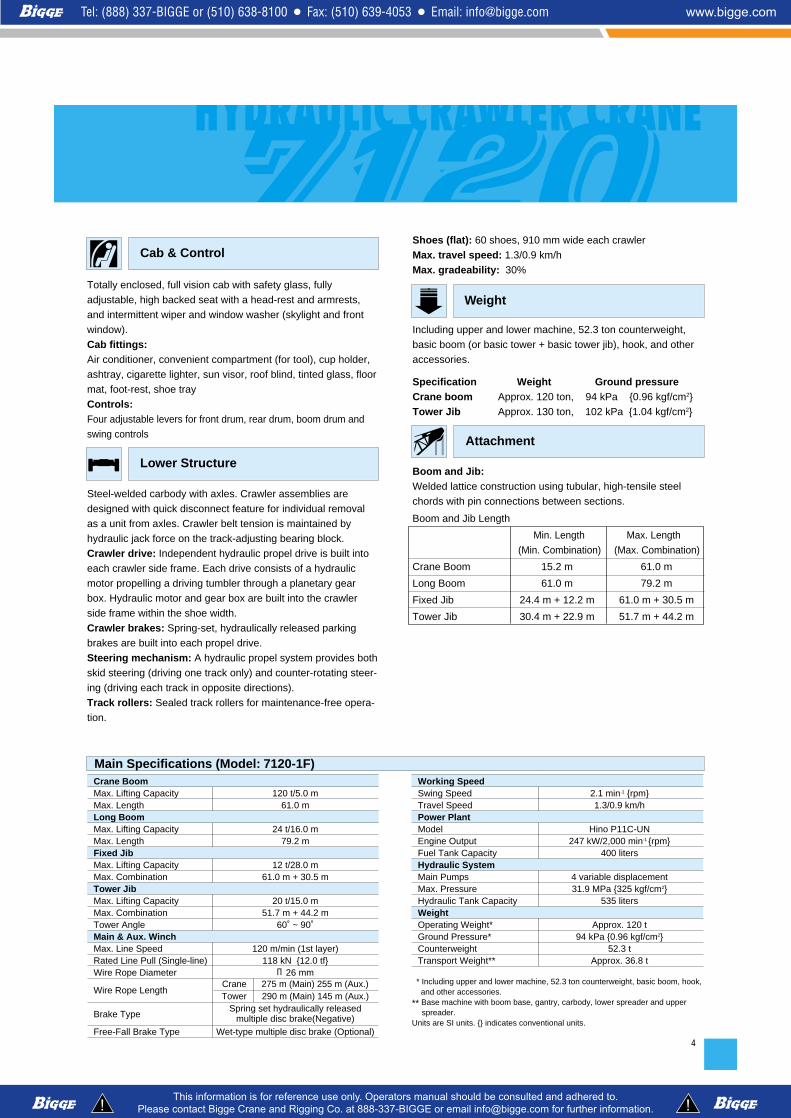
Totally enclosed, full vision cab with safety glass, fullyadjustable, high backed seat with a head-rest and armrests,and intermittent wiper and window washer (skylight and frontwindow).
Cab fittings:Air conditioner, convenient compartment (for tool), cup holder,ashtray, cigarette lighter, sun visor, roof blind, tinted glass, floormat, foot-rest, shoe tray
Controls:Four adjustable levers for front drum, rear drum, boom drum andswing controls
Steel-welded carbody with axles. Crawler assemblies aredesigned with quick disconnect feature for individual removalas a unit from axles. Crawler belt tension is maintained byhydraulic jack force on the track-adjusting bearing block.
Crawler drive: Independent hydraulic propel drive is built intoeach crawler side frame. Each drive consists of a hydraulicmotor propelling a driving tumbler through a planetary gearbox. Hydraulic motor and gear box are built into the crawlerside frame within the shoe width.
Crawler brakes: Spring-set, hydraulically released parkingbrakes are built into each propel drive.Steering mechanism: A hydraulic propel system provides bothskid steering (driving one track only) and counter-rotating steer-ing (driving each track in opposite directions).
Track rollers: Sealed track rollers for maintenance-free opera-tion.
4
Lower Structure
Main Specifications (Model: 7120-1F)
Shoes (flat): 60 shoes, 910 mm wide each crawlerMax. travel speed: 1.3/0.9 km/hMax. gradeability: 30%
Including upper and lower machine, 52.3 ton counterweight,basic boom (or basic tower + basic tower jib), hook, and otheraccessories.
Specification Weight Ground pressureCrane boom Approx. 120 ton, 94 kPa {0.96 kgf/cm2}Tower Jib Approx. 130 ton, 102 kPa {1.04 kgf/cm2}
Boom and Jib:Welded lattice construction using tubular, high-tensile steelchords with pin connections between sections.
Boom and Jib Length
Min. Length Max. Length(Min. Combination) (Max. Combination)
Crane Boom 15.2 m 61.0 m
Long Boom 61.0 m 79.2 m
Fixed Jib 24.4 m + 12.2 m 61.0 m + 30.5 m
Tower Jib 30.4 m + 22.9 m 51.7 m + 44.2 m
Weight
Attachment
Crane BoomMax. Lifting Capacity 120 t/5.0 mMax. Length 61.0 mLong BoomMax. Lifting Capacity 24 t/16.0 mMax. Length 79.2 mFixed JibMax. Lifting Capacity 12 t/28.0 mMax. Combination 61.0 m + 30.5 mTower JibMax. Lifting Capacity 20 t/15.0 mMax. Combination 51.7 m + 44.2 mTower Angle 60˚ ~ 90˚Main & Aux. WinchMax. Line Speed 120 m/min (1st layer)Rated Line Pull (Single-line) 118 kN {12.0 tf}Wire Rope Diameter φ26 mm
Wire Rope LengthCrane 275 m (Main) 255 m (Aux.) Tower 290 m (Main) 145 m (Aux.)
Brake TypeSpring set hydraulically released
multiple disc brake(Negative)Free-Fall Brake Type Wet-type multiple disc brake (Optional)
Working SpeedSwing Speed 2.1 min-1 {rpm}Travel Speed 1.3/0.9 km/hPower PlantModel Hino P11C-UNEngine Output 247 kW/2,000 min-1 {rpm}Fuel Tank Capacity 400 litersHydraulic SystemMain Pumps 4 variable displacementMax. Pressure 31.9 MPa {325 kgf/cm2}Hydraulic Tank Capacity 535 litersWeightOperating Weight* Approx. 120 tGround Pressure* 94 kPa {0.96 kgf/cm2}Counterweight 52.3 tTransport Weight** Approx. 36.8 t
* Including upper and lower machine, 52.3 ton counterweight, basic boom, hook,and other accessories.
** Base machine with boom base, gantry, carbody, lower spreader and upper spreader.
Units are SI units. {} indicates conventional units.

5
GENERAL DIMENSIONS
4,035 2,080
6,530
R4,950
7,88
5
7,895
6,890
3,57
0 2,20
01,
340
1,400
Crane Boom Length: 15.2 m - 61.0 m
3,58
02,
525
6,310
910
480
3,2004,200
9401,600
Crane Boom
Limit of Hook Lifting
L L'Hook L
120 t hook 5.0 m
70 t hook 5.0 m
35 t hook 5.0 m
Hook L'
12 t ball hook 4.2 m
(Unit: mm )

2,52
5
1,400
Tower Angle
Tower
Jib
Leng
th: 2
2.9m
- 44
.2m
Tow
er L
engt
h: 3
0.4m
- 5
1.7m
(60° - 90°)
15° - 75° Jib Offset Angle is Limited.Jib Offset Angle is Limited. (Over 15°)
6
Tower Jib (Unit: mm )
7
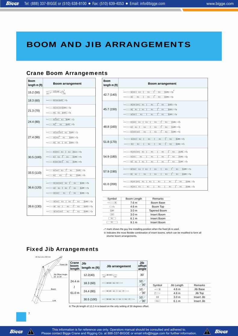
Boom length m (ft) Boom arrangement
15.2 (50)
18.3 (60)
21.3 (70)
24.4 (80)
27.4 (90)
30.5 (100)
33.5 (110)
36.6 (120)
39.6 (130)
Boom length m (ft) Boom arrangement
42.7 (140)
45.7 (150)
48.8 (160)
51.8 (170)
54.9 (180)
57.9 (190)
61.0 (200)
mark shows the guy line installing position when the fixed jib is used.
Indicates the most flexible combination of insert booms, which can be modified to form all shorter boom arrangements.
Symbol Boom Length7.6 m4.6 m3.0 m3.0 m6.1 m9.1 m
RemarksBoom BaseBoom Top
Tapered BoomInsert BoomInsert BoomInsert Boom
3.0T3.0B※
3.0T
3.0T
3.0T
B 6.16.1
9.1
3.0
6.1B
3.0 9.1B 3.0
※
3.0T
3.0T
B 6.1
B
3.0
9.1
※
3.0T
3.0T
B
B
9.13.0
6.16.1
3.0TB 3.03.0 6.1※
3.0T
3.0T9.1 9.1
6.1 9.13.0B
B
※
3.0T
3.0T
B
B
3.03.0
6.1
※
7.6 4.63.0TB
T
3.0T
3.0T
3.0T
9.1
9.1
9.1
9.1
3.0 3.0B 6.1
3.0B
6.1B 6.1
※
3.0T
3.0T
3.0T
9.1
9.1
9.13.0
3.0 9.1B
9.1
3.0
6.1B 6.1
6.1B
※
9.1
9.1
9.1
3.0T9.1
3.0T
3.0T9.1
3.0 3.0B 6.1
3.0B
6.1B 6.1 9.1
9.1
※
3.0 6.1 6.1 9.1B 3.0T3.0 9.19.1
6.1
※
9.1 9.1B 3.0T3.0 9.19.1
3.0
6.1
B
3.0T
9.1
6.1 9.1B 6.1 3.0T3.0 9.19.1
6.1
※
9.19.1B 3.0T9.19.1
6.16.1B 9.1 3.0T9.19.1
3.0 9.1 9.13.0
B 9.19.1 3.0T9.19.13.0
3.0T6.1B 9.1※
9.1 9.1 9.13.0 3.0T6.1B※
9.19.1 9.1 9.1 3.0TB
9.1
9.1
9.1
3.0T
3.0T
3.0T
9.1
9.1
9.13.0
3.0 9.1B
9.1
3.0
6.1B 6.1
6.1B
※
9.1 9.1
9.1
9.1 3.0T
3.0T9.13.0 6.1B
B
※ T
Crane Boom Arrangements
BOOM AND JIB ARRANGEMENTS
Crane boom length
Jib arrangementJib length m (ft)
12.2(40)
18.3 (60)
24.4 (80)
30.5 (100)
24.4 m
61.0 mBoom
Link
Fixed Jib
B T6.13.0
3.0B T6.1 6.1
T3.0B 6.1 6.1 6.1
B T3.04.6 4.6
Jib Offset Angle: 10° or 30°
Jib Guy Line: 26 mm
Jib offsetangle
10° 30°
10° 30°
10° 30°
30°
The jib length of 12.2 m is based on the only setting of 30 degrees offset.
3.0
6.1
B
Symbol Jib Length4.6 m4.6 m3.0 m6.1 m
RemarksJib BaseJib Top
Insert JibInsert Jib
T
Fixed Jib Arrangements

8
Long Boom ArrangementsBoom length m (ft) Long Boom arrangement
61.0 (200)
64.0 (210)
67.1 (220)
70.1 (230)
73.2 (240)
76.2 (250)
79.2 (260)
Symbol Long Boom Length7.6 m7.6 m3.0 m6.1 m9.1 m3.0 m3.0 m3.0 m6.1 m9.1 m
RemarksBoom Base
Tower Jib TopInsert BoomInsert BoomInsert Boom
Tapered BoomRelay Jib
Tower Insert JibTower Insert JibTower Insert Jib
Indicates the most flexible combination of insert long booms, which can be modified to form all shorter long boom arrangements.
9.1 6.1B 9.1 3.0A6.16.13.0 9.1 3.0T
9.1
6.1
6.1
9.1 9.13.03.0A6.16.13.0B 9.19.1 3.0T
9.1 9.16.13.0T9.1 9.13.0 6.1B 6.1 3.0A
9.1
3.0T
3.0
B
3.0A
9.1 3.0T9.13.0 6.16.1B 9.1 3.0A※
9.1 3.03.0T9.13.0 6.1 6.1 3.0A9.1B※
9.1 6.13.03.0T9.13.0 6.1 6.1 3.0A9.1B※
9.1T
3.0T9.16.16.1B 9.1 3.0A
7.6 7.6
3.0
22.9 mJib lengthTower length
90°-60°
90°-60°
90°-60°
90°-60°
90°-60°
90°-60°
90°-60°
90°-60°
90°-60°
90°-60°
90°-60°
90°-60°
90°-60°
90°-60°
90°-60° 90°-60°
90°-60°
90°-60°
90°-60°
90°-60°
90°-60°
90°-60°
90°-60°
90°-60°
90°-60°
90°-60°
90°-60°
90°-60°
90°-60°
90°-60°
90°-60°
90°-60°
90°-70° 90°-70°
90°-70°
30.4 m
33.4 m
36.5 m
39.5 m
42.5 m
45.6 m
48.6 m
90°-60° 90°-60° 90°-60° 90°-60° 90°-70° 90°-70° 90°-70° Need51.7 m
35 ton hook
Ball hookHoo
k
25.9 m 29.0 m 32.0 m 35.1 m 38.1 m 41.1 m
90°-70°
90°-70°
44.2 m Pillowplate
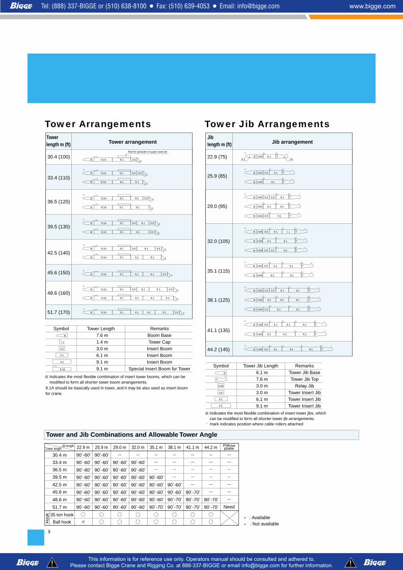
○ : Available× : Not available
Indicates the most flexible combination of insert tower jibs, which can be modified to form all shorter tower jib arrangements.
Symbol Tower Length 7.6 m 1.4 m 3.0 m 6.1 m 9.1 m 9.1 m
RemarksBoom BaseTower Cap
Insert BoomInsert BoomInsert Boom
Special Insert Boom for Tower
Indicates the most flexible combination of insert tower booms, which can bemodified to form all shorter tower boom arrangements.
9.1A should be basically used in tower, and it may be also used as insert boom for crane.
○ mark indicates position where cable rollers attached
Symbol Tower Jib Length 6.1 m 7.6 m 3.0 m 3.0 m 6.1 m 9.1 m
RemarksTower Jib BaseTower Jib Top
Relay JibTower Insert JibTower Insert JibTower Insert Jib
Towerlength m (ft) Tower arrangement
30.4 (100)
33.4 (110)
36.5 (120)
39.5 (130)
42.5 (140)
45.6 (150)
48.6 (160)
51.7 (170)
Jib length m (ft) Jib arrangement
22.9 (75)
25.9 (85)
29.0 (95)
32.0 (105)
35.1 (115)
38.1 (125)
41.1 (135)
44.2 (145)
B 9.1A 9.1C
3.0
B
※
9.1A 9.1C
3.0 3.0
B 6.1C
9.1A 9.1
B 9.1A 6.1 C
※ 9.1 3.0
B 9.1A 9.19.1 C
※ B 9.1A C9.1 9.13.0 3.0
6.1B 9.1A C9.1 9.1
B 9.1A 6.1 C
※ 9.1 9.1 3.0
B 9.1A 6.1 C
※ 9.1 9.13.0 3.0
B 9.1A 6.16.1 C9.1 9.1
C9.1B 9.1A 6.16.1※
9.1 3.0
C
9.1
9.1A
6.1
B
3.0
B 9.1A 6.1 C
※ 9.1 3.0 3.0
9.1 CB 9.1A 9.1 3.0
※ 3.0A TB 6.1
3.0A 3.0 6.1※ TB 9.1
9.19.13.0A TB
3.0A 3.0 6.1※ TB 9.19.1
3.0A
3.0
B
6.1
T
9.1
3.0A 3.0 6.16.1※ TB 9.1
3.0A 6.1 TB 9.19.1
3.0A 3.0 3.0 6.1※ TB 9.1
3.0A 6.16.1 TB 9.1
3.0A 3.0 TB 9.19.1
3.0A 3.0 3.0 6.1※ TB
9.13.0A 3.0 TB
3.0A 6.16.1 TB
3.0A 3.0 6.1※ TB
3.0A 9.1 TB
3.0A 3.0 6.1 6.1※ TB
9.13.0A 3.0 3.0 TB
9.13.0A 6.1 TB
Rail for spreader of upper tower jib
7.66.1
Tower Arrangements Tower Jib Arrangements
9
Tower and Jib Combinations and Allowable Tower Angle

10
A range of hook blocks can be specified, each with a safety latch.
Hook Blocks
No. of lines and max. rated loads (tons)Hooks Weight (kg) No. of
1 2 3 4 5sheaves
120-ton 1,700 5 - - - 48.0 60.070-ton 1,200 3 - 24.0 36.0 48.0 60.035-ton 900 1 - 24.0 35.0 - -
12-ton 450 0 12.0 - - - -ball hook
No. of lines and max. rated loads (tons)Hooks Weight (kg) No. of
6 7 8 9 10sheaves
120-ton 1,700 5 72.0 84.0 96.0 108.0 120.070-ton 1,200 3 70.0 - - - -35-ton 900 1 - - - - -12-ton 450 0 - - - - -ball hook
Symbols for Attachments:
Crane BoomAuxiliary Sheavefor Crane Boom Tower JibLong Boom Fixed Jib
Auxiliary Sheavefor Long Boom

11
WORKING RANGESAND LIFTING CAPACITIES
Hei
gh
t ab
ove
gro
un
d (
m)
Radius from center of rotation (m)
2.53
m
1.4m
61.0m BOOM
60˚65゚ 70˚75˚80˚ 55˚
57.9m BOOM
54.9m BOOM
51.8m BOOM
48.8m BOOM
45.7m BOOM
42.7m BOOM
39.6m BOOM
36.6m BOOM
33.5m BOOM
30.5m BOOM
27.4m BOOM
24.4m BOOM
21.3m BOOM
15.2m BOOM
18.3m BOOM
56
20
44
16
60
Center of rotation
403632282420161284
56
52
48
44
40
36
32
28
24
48 52
64
40˚
45˚
50˚
30˚
35˚
Crane Boom Working Ranges
NOTES:1. Ratings according to Japanese Construction Codes for Mobile Cranes
and Japanese Safety Ordinance on Cranes, etc.2. Ratings in metric tons for 360˚ working area.3. Operating radius is the horizontal distance from center of rotation to a
vertical line through the center of gravity of the load.4. Weight of hook block(s), slings and other load handling accessories is
included in rated load. Their total weight must be subtracted from ratedload to obtain weight that can be lifted.
5. Ratings shown are based on freely suspended loads and make noallowance for such factors as wind effect on lifted load, ground condi-tions out-of-level, operating speeds or any other condition that could bedetrimental to the safe operation of this equipment. Operator, therefore,has the responsibility to judge the existing conditions and reduce liftedloads and operating speeds accordingly.
6. Ratings are for operation on a firm and level surface.7. At radii and boom lengths where no ratings are shown on chart, opera-
tion is not intended nor approved.
8. Boom inserts and guy lines must be arranged as shown in the“Operator's Manual”.
9. Boom hoist reeving is 12 part line.10. Gantry must be in raised position for all conditions.11. Boom backstops are required for all boom lengths.12. Ratings shown in are determined by the strength of the boom
or other structural component.13. Instruction in the “Operator's Manual” must be strictly observed when
operating the machine.14. Crane boom ratings: Deduct weight of main hook block, slings, and all
other load handling accessories from crane boom ratings shown.15. Auxiliary sheave ratings for crane boom: Deduct weight of ball hook,
slings, and all other load handling accessories from auxiliary sheave rat-ings shown.
16. Crane boom lengths for auxiliary sheave mounting are 15.2 m to 61.0 m.17. Crane boom ratings with auxiliary sheave: Deduct 0.8 ton from crane
boom ratings shown. Minimum rated loads must exceed 2.0 ton.

Unit: metric ton
12
Crane Boom Lifting CapacityBoom
Length (m)Working
radius (m)
4.5 m/120.0120.0100.0 85.7 73.7 61.5 52.6 40.6 33.0
14.9 m/29.1
10
5.1 m/108.0 99.8 85.5 73.6 61.3 52.5 40.5 32.8 27.5
17.5 m/24.5
9
5.6 m/96.094.985.373.561.252.340.332.627.323.320.3
20.1 m/20.2
8
15.2 18.3 21.3 24.4
6.1 m/84.081.573.561.152.240.232.527.223.220.217.8
22.8 m/17.1
7
27.4
6.7m/74.673.771.361.052.140.032.326.923.020.017.615.6
25.4 m/14.5
7
30.5
7.2 m/66.464.760.952.040.032.326.922.919.917.515.513.912.6
6
33.5
8.2 m/53.652.551.239.732.026.622.619.517.115.213.612.211.110.1
33.3 m/9.5
5
7.7m/59.458.957.252.039.932.226.822.819.817.415.413.812.511.3
30.7 m/11.0
5
36.6
4.5 5.0 6.0 7.0 8.0 9.010.012.014.016.018.020.022.024.026.028.030.032.034.036.038.040.042.044.0
Reeves
Boom Length (m) Working
radius (m)
4.5 5.0 6.0 7.0 8.0 9.010.012.014.016.018.020.022.024.026.028.030.032.034.036.038.040.042.044.0
Reeves
Boom Length
(m)Working radius (m)
39.6
8.8 m/48.048.046.839.731.926.522.519.517.115.113.512.111.010.0 9.1 8.4
4
42.7
9.3 m/43.542.839.531.826.422.419.316.914.913.312.010.8 9.8 8.9 8.2 7.5
38.6m/7.4
4
45.7
9.8 m/39.639.537.831.626.222.219.116.714.713.111.710.6 9.6 8.7 8.0 7.3 6.7
41.2 m/6.4
4
48.8
10.4 m/36.034.731.626.122.119.116.614.713.011.710.5 9.5 8.6 7.9 7.2 6.6 6.1
43.9 m/5.63
51.8
10.9 m/32.131.430.126.022.018.916.514.512.911.510.3 9.3 8.5 7.7 7.0 6.4 5.9 5.4 5.0
46.5 m/4.9
3
57.954.9
11.4 m/29.429.027.925.821.818.716.314.312.711.310.1 9.1 8.2 7.5 6.8 6.2 5.7 5.2 4.7 4.3
49.2 m/4.1
3
12.5 m/24.023.522.821.418.516.014.112.411.0 9.9 8.9 8.0 7.2 6.5 5.9 5.4 4.9 4.4 3.9 3.5 3.1 2.7
54.4 m/2.72
26.925.924.921.618.616.114.112.511.110.0 9.0 8.1 7.3 6.6 6.0 5.5 5.0 4.6 4.1 3.7
51.8 m/3.3
3
61.0
10.012.014.016.018.020.022.024.026.028.030.032.034.036.038.040.042.044.046.048.050.052.054.056.0
Reeves
Boom Length (m) Working
radius (m)
10.012.014.016.018.020.022.024.026.028.030.032.034.036.038.040.042.044.046.048.050.052.054.056.0
Reeves
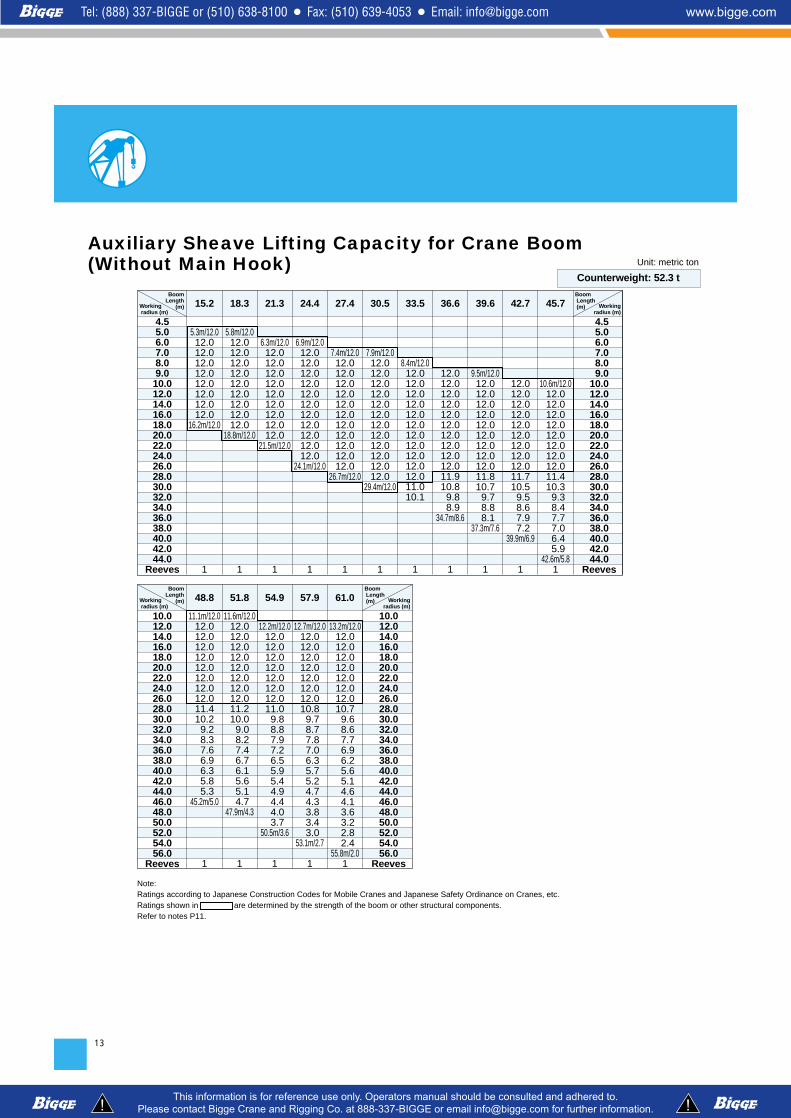
Counterweight: 52.3 t
Note: Ratings according to Japanese Construction Codes for Mobile Cranes and Japanese Safety Ordinance on Cranes, etc.Ratings shown in are determined by the strength of the boom or other structural components.Refer to notes P11.
13
Unit: metric ton
Auxiliary Sheave Lifting Capacity for Crane Boom(Without Main Hook)
Boom Length
(m)Working radius (m)
5.3m/12.012.012.012.012.012.012.012.012.0
16.2m/12.0
1
5.8m/12.012.012.012.012.012.012.012.012.012.0
18.8m/12.0
1
6.3m/12.012.012.012.012.012.012.012.012.012.0
21.5m/12.0
1
15.2 18.3 21.3 24.4
6.9m/12.012.012.012.012.012.012.012.012.012.012.012.0
24.1m/12.0
1
27.4
7.4m/12.012.012.012.012.012.012.012.012.012.012.012.0
26.7m/12.0
1
30.5
7.9m/12.012.012.012.012.012.012.012.012.012.012.012.012.0
29.4m/12.0
1
33.5
8.4m/12.012.012.012.012.012.012.012.012.012.012.012.011.010.1
1
4.55.06.07.08.09.010.012.014.016.018.020.022.024.026.028.030.032.034.036.038.040.042.044.0
Reeves
Boom Length
(m)Working radius (m)
12.012.012.012.012.012.012.012.012.012.011.910.8 9.8 8.9
34.7m/8.6
1
36.6 39.6
9.5m/12.012.012.012.012.012.012.012.012.012.011.810.7 9.7 8.8 8.1
37.3m/7.6
1
42.7
12.012.012.012.012.012.012.012.012.011.710.5 9.5 8.6 7.9 7.2
39.9m/6.9
1
45.7
10.6m/12.012.012.012.012.012.012.012.012.011.410.3 9.3 8.4 7.7 7.0 6.4 5.9
42.6m/5.81
48.8
11.1m/12.012.012.012.012.012.012.012.012.011.410.2 9.2 8.3 7.6 6.9 6.3 5.8 5.3
45.2m/5.0
1
51.8
11.6m/12.012.012.012.012.012.012.012.012.011.210.0 9.0 8.2 7.4 6.7 6.1 5.6 5.1 4.7
47.9m/4.3
1
57.954.9
12.2m/12.012.012.012.012.012.012.012.011.0 9.8 8.8 7.9 7.2 6.5 5.9 5.4 4.9 4.4 4.0 3.7
50.5m/3.6
1
13.2m/12.012.012.012.012.012.012.012.010.7 9.6 8.6 7.7 6.9 6.2 5.6 5.1 4.6 4.1 3.6 3.2 2.8 2.4
55.8m/2.01
12.7m/12.012.012.012.012.012.012.012.010.8 9.7 8.7 7.8 7.0 6.3 5.7 5.2 4.7 4.3 3.8 3.4 3.0
53.1m/2.7
1
61.0
10.012.014.016.018.020.022.024.026.028.030.032.034.036.038.040.042.044.046.048.050.052.054.056.0
Reeves
Boom Length (m) Working
radius (m)
4.5 5.0 6.0 7.0 8.0 9.010.012.014.016.018.020.022.024.026.028.030.032.034.036.038.040.042.044.0
Reeves
Boom Length (m) Working
radius (m)
10.012.014.016.018.020.022.024.026.028.030.032.034.036.038.040.042.044.046.048.050.052.054.056.0
Reeves
Counterweight: 52.3 t
Note: Ratings according to Japanese Construction Codes for Mobile Cranes and Japanese Safety Ordinance on Cranes, etc.Ratings shown in are determined by the strength of the boom or other structural components.Refer to notes P11.
14
2.53
m
1.4m
6460
79.2m BOOM
76.2m BOOM
73.2m BOOM
70.1m BOOM
67.1m BOOM
64.0m BOOM
61.0m BOOM
60˚65˚70˚75˚80˚ 55˚
5644
60
4036322824201612
56
52
48
44
40
36
32
48 52
64
68
72
76
80
Center of rotation
Hei
gh
t ab
ove
gro
un
d (
m)
Radius from center of rotation (m)
40˚
45˚
50˚
30˚
35˚
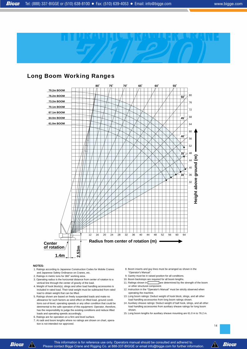
Long Boom Working Ranges
NOTES:1. Ratings according to Japanese Construction Codes for Mobile Cranes
and Japanese Safety Ordinance on Cranes, etc.2. Ratings in metric tons for 360˚ working area.3. Operating radius is the horizontal distance from center of rotation to a
vertical line through the center of gravity of the load.4. Weight of hook block(s), slings and other load handling accessories is
included in rated load. Their total weight must be subtracted from ratedload to obtain weight that can be lifted.
5. Ratings shown are based on freely suspended loads and make noallowance for such factors as wind effect on lifted load, ground condi-tions out-of-level, operating speeds or any other condition that could bedetrimental to the safe operation of this equipment. Operator, therefore,has the responsibility to judge the existing conditions and reduce liftedloads and operating speeds accordingly.
6. Ratings are for operation on a firm and level surface.7. At radii and boom lengths where no ratings are shown on chart, opera-
tion is not intended nor approved.
8. Boom inserts and guy lines must be arranged as shown in the“Operator's Manual”.
9. Gantry must be in raised position for all conditions.10. Boom backstops are required for all boom lengths.11. Ratings shown in are determined by the strength of the boom
or other structural component.12. Instruction in the “Operator's Manual” must be strictly observed when
operating the machine.13. Long boom ratings: Deduct weight of hook block, slings, and all other
load handling accessories from long boom ratings shown.14. Auxiliary sheave ratings: Deduct weight of ball hook, slings, and all other
load handling accessories from auxiliary sheave ratings for long boomshown.
15. Long boom lengths for auxiliary sheave mounting are 61.0 m to 76.2 m.

15
Unit: metric tonLong Boom Lifting CapacityBoom
Length (m)Working
radius (m)
12.3 m/24.024.024.022.819.717.315.313.712.311.110.1 9.2 8.4 7.8 7.2 6.6 6.1 5.7 5.3 4.9 4.6 4.3
54.4m/4.2
2
12.8m/24.024.024.022.619.517.115.113.512.110.9 9.9 9.0 8.3 7.6 7.0 6.4 5.9 5.5 5.1 4.7 4.4 4.1 3.8
57.0 m/3.6
2
13.3 m/24.024.024.022.519.517.015.013.412.010.8 9.8 8.9 8.2 7.5 6.9 6.3 5.8 5.4 5.0 4.6 4.3 3.9 3.7 3.4
59.7 m/3.1
2
61.0 64.0 67.1
13.9 m/24.024.024.022.519.417.015.013.412.010.8 9.8 8.9 8.1 7.5 6.8 6.3 5.8 5.3 4.9 4.6 4.2 3.9 3.6 3.3 3.0 2.8
62.3 m/2.7
2
70.1
14.4m/22.120.919.518.316.914.913.311.910.7 9.7 8.8 8.0 7.4 6.7 6.2 5.7 5.2 4.8 4.5 4.1 3.8 3.5 3.2 2.9 2.6 2.4
64.9 m/2.22
73.2
14.9 m/18.717.916.715.714.814.013.111.710.6 9.5 8.7 7.9 7.2 6.6 6.0 5.5 5.1 4.7 4.3 4.0 3.6 3.3 2.9 2.6 2.4 2.1
2
76.2
15.4 m/16.315.914.813.913.112.311.711.210.5 9.5 8.6 7.8 7.2 6.5 6.0 5.5 5.0 4.6 4.3 3.9 3.5 3.2 2.9 2.6 2.3 2.0
2
79.2
12.014.016.018.020.022.024.026.028.030.032.034.036.038.040.042.044.046.048.050.052.054.056.058.060.062.064.066.0
Reeves
Boom Length (m) Working
radius (m)
12.014.016.018.020.022.024.026.028.030.032.034.036.038.040.042.044.046.048.050.052.054.056.058.060.062.064.066.0
Reeves
Boom Length
(m)Working radius (m)
12.9m/12.012.012.012.012.012.012.012.012.010.8 9.8 8.9 8.1 7.5 6.9 6.3 5.8 5.4 5.0 4.6 4.3 4.0
55.1m/3.7
2
13.4m/12.012.012.012.012.012.012.012.011.810.6 9.6 8.7 8.0 7.3 6.7 6.1 5.6 5.2 4.8 4.4 4.1 3.8 3.5
57.8m/3.2
2
12.012.012.012.012.012.012.011.710.5 9.5 8.6 7.9 7.2 6.6 6.0 5.5 5.1 4.7 4.3 4.0 3.6 3.4 3.1 2.8
60.4m/2.7
2
61.0 64.0 67.1
14.5m/12.012.012.012.012.012.012.011.710.5 9.5 8.6 7.8 7.2 6.5 6.0 5.5 5.0 4.6 4.3 3.9 3.6 3.3 3.0 2.7 2.5
63.0m/2.4
2
70.1
15.0m/12.012.012.012.012.012.012.011.610.4 9.4 8.5 7.7 7.1 6.4 5.9 5.4 4.9 4.5 4.2 3.8 3.5 3.2 2.9 2.6 2.3 2.1
2
73.2
15.5m/12.012.012.012.012.012.012.011.410.3 9.2 8.4 7.6 6.9 6.3 5.7 5.2 4.8 4.4 4.0 3.7 3.3 3.0 2.6 2.3 2.1
2
76.2
12.014.016.018.020.022.024.026.028.030.032.034.036.038.040.042.044.046.048.050.052.054.056.058.060.062.064.066.0
Reeves
Boom Length (m) Working
radius (m)
12.014.016.018.020.022.024.026.028.030.032.034.036.038.040.042.044.046.048.050.052.054.056.058.060.062.064.066.0
Reeves
Counterweight: 52.3 t
Unit: metric ton
Counterweight: 52.3 t
Note: Ratings according to JapaneseConstruction Codes for Mobile Cranesand Japanese Safety Ordinance onCranes, etc.Ratings shown in are deter-mined by the strength of the boom orother structural components.Refer to notes P14.
Note: Ratings according to Japanese Construction Codesfor Mobile Cranes and Japanese Safety Ordinanceon Cranes, etc.Ratings shown in are determined by thestrength of the boom or other structural components.Refer to notes P14.
Auxiliary Sheave Lifting Capacity for Long Boom(Without Main Hook)

Radius from center of rotation (m)
Hei
gh
t ab
ove
gro
un
d (
m)
60
92
88
84
80
76
72
68
56 6864
64
5248
20
44
60
403632282420161284
56
52
48
44
40
36
32
28
24
30˚2.
53m
30˚
80˚
10˚
1.4m
61.0 m BOOM + 30.5 m JIB
61.0 m BOOM + 24.4 m JIB
61.0 m BOOM + 18.3 m JIB
61.0 m BOOM + 12.2 m JIB
24.4 m BOOM + 30.5 m JIB
24.4 m BOOM + 24.4 m JIB
24.4 m BOOM + 18.3 m JIB
24.4 m BOOM + 12.2 m JIB
Center of rotation
16
NOTES:1. Ratings according to Japanese Construction Codes for Mobile Cranes
and Japanese Safety Ordinance on Cranes, etc.2. Ratings in metric tons for 360˚ working area.3. Operating radius is the horizontal distance from center of rotation to a
vertical line through the center of gravity of the load.4. Weight of hook block(s), slings and other load handling accessories is
included in rated load. Their total weight must be subtracted from ratedload to obtain weight that can be lifted.
5. Ratings shown are based on freely suspended loads and make noallowance for such factors as wind effect on lifted load, ground condi-tions out-of-level, operating speeds or any other condition that could bedetrimental to the safe operation of this equipment. Operator, therefore,has the responsibility to judge the existing conditions and reduce liftedloads and operating speeds accordingly.
6. Ratings are for operation on a firm and level surface.7. At radii and boom lengths where no ratings are shown on chart, opera-
tion is not intended nor approved.
8. Boom/jib inserts and guy lines must be arranged as shown in the“Operator's Manual”.
9. Gantry must be in raised position for all conditions.10. Boom backstops are required for all boom lengths.11. Ratings shown in are determined by the strength of the boom
or other structural component.12. Instruction in the “Operator's Manual” must be strictly observed when
operating the machine.13. Fixed jib ratings: Deduct weight of jib hook block, slings, and all other
load handling accessories from jib ratings shown.14. Crane boom lengths for fixed jib mounting are 24.4 m to 61.0 m.15. The jib length of 12.2 m is based on the only setting of 30 degrees offset.
Fixed Jib Working Ranges Jib Offset Angle: 10°, 30°

17
Fixed Jib Lifting Capacities (Without Main Hook)Jib Offset Angle: 10°
Unit: metric ton
18.3
14.4 m/12.0
12.0
12.0
12.0
12.0
12.0
12.0
12.0
11.5
9.6
8.1
6.9
6.0
5.2
1
24.4
16.4 m/8.0
8.0
8.0
8.0
7.9
7.6
7.3
7.1
6.6
6.2
5.9
5.6
5.4
4.7
56.0 m/4.5
1
30.5
18.5 m/4.0
4.0
4.0
4.0
4.0
4.0
4.0
3.8
3.5
3.3
3.1
2.9
2.7
2.6
60.0 m/2.5
1
18.3
15.4 m/12.0
12.0
12.0
12.0
12.0
12.0
12.0
12.0
11.2
9.3
7.8
6.6
5.7
4.9
4.2
56.0 m/3.9
1
24.4
17.5 m/8.0
8.0
8.0
8.0
8.0
7.9
7.6
7.4
6.9
6.5
6.2
5.9
5.1
4.4
3.9
60.0 m/3.6
1
30.5
19.6 m/4.0
4.0
4.0
4.0
4.0
4.0
4.0
4.0
3.7
3.4
3.2
3.0
2.9
2.7
2.6
2.5
1
18.3
18.6 m/12.0
12.0
12.0
12.0
12.0
11.4
10.2
8.2
6.7
5.5
4.5
3.6
2.8
2.1
1
24.4
20.7 m/8.0
8.0
8.0
8.0
8.0
8.0
7.6
7.1
5.9
4.9
4.1
3.2
2.5
60.0 m/2.2
1
30.5
22.8 m/4.0
4.0
4.0
4.0
4.0
4.0
4.0
3.9
3.7
3.5
3.3
2.7
2.1
1
18.3
12.2 m/12.0
12.0
12.0
12.0
12.0
12.0
12.0
12.0
11.8
11.0
9.7
8.7
40.0 m/8.3
1
24.4
14.3 m/8.0
8.0
8.0
8.0
7.6
7.3
7.0
6.7
6.4
6.0
5.6
5.3
44.0 m/5.2
1
30.5
16.4 m/4.0
4.0
4.0
4.0
4.0
4.0
3.9
3.7
3.4
3.1
2.9
2.7
2.6
1
24.4 30.5 36.6 42.7
18.3
13.3 m/12.0
12.0
12.0
12.0
12.0
12.0
12.0
12.0
12.0
11.9
10.0
8.5
7.3
44.0 m/6.9
1
24.4
15.4 m/8.0
8.0
8.0
8.0
8.0
7.6
7.3
7.0
6.8
6.3
5.9
5.6
5.4
5.2
1
30.5
17.5 m/4.0
4.0
4.0
4.0
4.0
4.0
4.0
3.9
3.6
3.3
3.1
2.9
2.7
2.6
56.0 m/2.5
1
Boom length (m)
Jib length (m)
Wo
rkin
g r
adiu
s (m
)
Boom length (m)
Jib length (m)
12.0
14.0
16.0
18.0
20.0
22.0
24.0
26.0
28.0
30.0
34.0
38.0
42.0
46.0
50.0
54.0
58.0
62.0
66.0
Reeves
12.0
14.0
16.0
18.0
20.0
22.0
24.0
26.0
28.0
30.0
34.0
38.0
42.0
46.0
50.0
54.0
58.0
62.0
66.0
Reeves
Wo
rking
radiu
s (m)
18.3
16.5 m/12.0
12.0
12.0
12.0
12.0
12.0
12.0
10.9
8.9
7.4
6.2
5.3
4.5
3.8
3.2
60.0 m/2.9
1
24.4
18.6 m/8.0
8.0
8.0
8.0
8.0
7.9
7.6
7.2
6.8
6.4
5.6
4.8
4.1
3.5
2.9
2.4
1
30.5
20.6 m/4.0
4.0
4.0
4.0
4.0
4.0
4.0
3.8
3.6
3.4
3.2
3.0
2.9
2.7
2.5
2.1
1
48.8 54.9 61.0
18.3
17.5 m/12.0
12.0
12.0
12.0
12.0
12.0
11.7
10.5
8.6
7.1
5.9
4.9
4.1
3.3
2.6
2.1
1
24.4
19.6 m/8.0
8.0
8.0
8.0
8.0
8.0
7.9
7.4
7.0
6.2
5.2
4.4
3.7
3.0
2.4
64.0 m/2.1
1
30.5
21.7 m/4.0
4.0
4.0
4.0
4.0
4.0
4.0
4.0
3.7
3.5
3.3
3.2
3.0
2.5
2.0
1
Boom length (m)
Jib length (m)
Wo
rkin
g r
adiu
s (m
)
Boom length (m)
Jib length (m)
16.0
18.0
20.0
22.0
24.0
26.0
28.0
30.0
34.0
38.0
42.0
46.0
50.0
54.0
58.0
62.0
66.0
70.0
Reeves
16.0
18.0
20.0
22.0
24.0
26.0
28.0
30.0
34.0
38.0
42.0
46.0
50.0
54.0
58.0
62.0
66.0
70.0
Reeves
Wo
rking
radiu
s (m)
Counterweight: 52.3 t
Note: Ratings according to Japanese Construction Codes for Mobile Cranes and Japanese Safety Ordinance on Cranes, etc.Ratings shown in are determined by the strength of the boom or other structural components. Refer to notes P16.※ The jib length of 12.2 m is based on the only setting of 30 degrees offset.

18
12.2
13.8 m/10.0
10.0
10.0
10.0
10.0
10.0
10.0
10.0
10.0
10.0
10.0
1
18.3
17.7 m/9.0
9.0
9.0
9.0
9.0
9.0
8.7
8.3
7.6
7.1
40.0 m/6.9
1
24.4
21.7 m/6.0
6.0
6.0
6.0
5.8
5.7
5.4
5.2
5.0
4.7
1
30.5
25.6 m/3.0
3.0
3.0
3.0
2.9
2.7
2.6
2.5
2.4
52.0 m/2.4
1
12.2
15.9 m/10.0
10.0
10.0
10.0
10.0
10.0
10.0
10.0
10.0
9.6
8.1
6.9
44.0 m/6.3
1
18.3
19.9 m/9.0
9.0
9.0
9.0
9.0
9.0
9.0
8.6
8.0
7.3
6.2
5.4
52.0 m/5.0
1
24.4
23.8 m/6.0
6.0
6.0
6.0
6.0
5.7
5.5
5.3
5.2
5.0
4.8
56.0 m/4.6
1
30.5
27.7 m/3.0
3.0
3.0
3.0
2.9
2.8
2.7
2.6
2.5
2.4
2.4
1
12.2
14.9 m/10.0
10.0
10.0
10.0
10.0
10.0
10.0
10.0
10.0
9.9
8.4
40.0 m/7.8
1
18.3
18.8 m/9.0
9.0
9.0
9.0
9.0
9.0
8.9
8.1
7.5
7.1
6.5
1
24.4
22.7 m/6.0
6.0
6.0
6.0
5.8
5.6
5.4
5.2
5.0
4.8
52.0 m/4.7
1
30.5
26.6 m/3.0
3.0
3.0
3.0
2.8
2.7
2.6
2.5
2.4
2.4
1
12.2
17.0 m/10.0
10.0
10.0
10.0
10.0
10.0
10.0
10.0
9.3
7.8
6.6
5.6
4.8
1
18.3
20.9 m/9.0
9.0
9.0
9.0
9.0
9.0
9.0
8.3
7.0
6.0
5.1
4.4
56.0 m/4.1
1
24.4
24.8 m/6.0
6.0
6.0
6.0
5.8
5.6
5.4
5.3
5.1
4.6
4.0
3.5
1
30.5
28.8 m/3.0
3.0
3.0
3.0
2.8
2.7
2.6
2.5
2.5
2.4
2.4
1
24.4 30.5 36.6 42.7Boom length (m)
Jib length (m)
Boom length (m)
Jib length (m)
12.0
14.0
16.0
18.0
20.0
22.0
24.0
26.0
28.0
30.0
34.0
38.0
42.0
46.0
50.0
54.0
58.0
62.0
66.0
Reeves
12.0
14.0
16.0
18.0
20.0
22.0
24.0
26.0
28.0
30.0
34.0
38.0
42.0
46.0
50.0
54.0
58.0
62.0
66.0
Reeves
Wo
rkin
g r
adiu
s (m
) Wo
rking
radiu
s (m)
12.2
18.1m/10.0
10.0
10.0
10.0
10.0
10.0
10.0
9.0
7.5
6.2
5.2
4.4
3.7
56.0 m/3.4
1
18.3
9.0
9.0
9.0
9.0
9.0
9.0
8.0
6.7
5.7
4.8
4.1
3.5
2.8
1
24.4
25.9 m/6.0
6.0
6.0
6.0
5.9
5.7
5.5
5.4
5.1
4.4
3.7
3.2
2.6
68.0 m/2.3
1
30.5
29.8 m/3.0
3.0
3.0
3.0
2.9
2.8
2.7
2.6
2.5
2.5
2.4
2.3
2.1
1
12.2
20.1 m/10.0
10.0
10.0
10.0
10.0
10.0
8.4
6.8
5.6
4.6
3.6
2.8
2.0
1
18.3
24.1 m/9.0
9.0
9.0
9.0
9.0
7.4
6.1
5.1
4.2
3.4
2.6
2.0
1
24.4
6.0
6.0
6.0
5.9
5.7
5.5
4.6
3.8
3.0
2.3
64.0 m/2.0
1
30.5
31.9 m/3.0
3.0
3.0
3.0
2.9
2.8
2.7
2.6
2.5
2.0
1
12.2
19.1 m/10.0
10.0
10.0
10.0
10.0
10.0
10.0
8.7
7.1
5.9
4.9
4.1
3.2
2.5
60.0 m/2.2
1
18.3
23.0 m/9.0
9.0
9.0
9.0
9.0
9.0
7.7
6.4
5.4
4.5
3.8
3.0
2.4
64.0 m/2.1
1
24.4
26.9 m/6.0
6.0
6.0
6.0
5.8
5.6
5.5
4.8
4.1
3.4
2.7
2.1
1
30.5
30.9 m/3.0
3.0
3.0
3.0
2.8
2.7
2.6
2.6
2.5
2.4
68.0 m/2.1
1
48.8 54.9 61.0Boom length (m)
Jib length (m)
Boom length (m)
Jib length (m)
18.0
20.0
22.0
24.0
26.0
28.0
30.0
34.0
38.0
42.0
46.0
50.0
54.0
58.0
62.0
66.0
70.0
72.0
Reeves
18.0
20.0
22.0
24.0
26.0
28.0
30.0
34.0
38.0
42.0
46.0
50.0
54.0
58.0
62.0
66.0
70.0
72.0
Reeves
Wo
rkin
g r
adiu
s (m
) Wo
rking
radiu
s (m)
Jib Offset Angle: 30° Counterweight: 52.3 t
Unit: metric ton
Note: Ratings according to Japanese Construction Codes for Mobile Cranes and Japanese Safety Ordinance on Cranes, etc.Ratings shown in are determined by the strength of the boom or other structural components. Refer to notes P16.※ The jib length of 12.2 m is based on the only setting of 30 degrees offset.
19
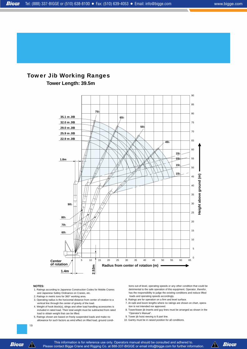
Tower Length: 39.5mTower Jib Working Ranges
Hei
gh
t ab
ove
gro
un
d (
m)
Radius from center of rotation (m)
80゚
70゚
60゚
2.53
m
1.4m
1.8m
90゚
15゚
15゚
15゚
65605550
90
85
80
75
70
10
20
5
0403510 30 4520 255 15
60
50
35
55
40
35.1 m JIB
32.0 m JIB
29.0 m JIB
25.9 m JIB
30
75゚
22.9 m JIB
45
65゚
55゚
45゚
15゚
15
65
25
Center of rotation
NOTES:1. Ratings according to Japanese Construction Codes for Mobile Cranes
and Japanese Safety Ordinance on Cranes, etc.2. Ratings in metric tons for 360° working area.3. Operating radius is the horizontal distance from center of rotation to a
vertical line through the center of gravity of the load.4. Weight of hook block(s), slings and other load handling accessories is
included in rated load. Their total weight must be subtracted from ratedload to obtain weight that can be lifted.
5. Ratings shown are based on freely suspended loads and make noallowance for such factors as wind effect on lifted load, ground condi-
tions out-of-level, operating speeds or any other condition that could be detrimental to the safe operation of this equipment. Operator, therefor, has the responsibility to judge the existing conditions and reduce liftedloads and operating speeds accordingly.
6. Ratings are for operation on a firm and level surface.7. At radii and boom lengths where no ratings are shown on chart, opera-
tion is not intended nor approved.8. Tower/tower jib inserts and guy lines must be arranged as shown in the
“Operator's Manual”.9. Tower jib hoist reeving is 8 part line.
10. Gantry must be in raised position for all conditions.

20
Hei
gh
t ab
ove
gro
un
d (
m)
Radius from center of rotation (m)
80゚
70゚
60゚
2.53
m
1.8m
1.4m
90゚
757065605550
100
95
90
85
80
75
70
10
20
5
0
25
30
35
40
45
50
55
60
65
15
15゚
15゚
15゚
45゚
55゚
65゚
403510 30 4520 255 15
44.2 m JIB
41.1 m JIB
38.1 m JIB
35.1 m JIB
32.0 m JIB
29.0 m JIB
25.9 m JIB
75゚
22.9 m JIB
15゚
Center of rotation
Tower Length: 51.7m
11. Tower and tower jib backstops are required for all tower and tower jib combinations.
12. Ratings shown in are determined by the strength of the toweror other structural component.
13. When erecting and lowering the tower length of 51.7 m, the pillow platefor erection must be placed at the end of crawlers.
14. Instruction in the “Operator's Manual” must be strictly observed whenoperating the machine.
15. Tower jib ratings: Deduct weight of hook block, slings, and all other loadhandling accessories from tower jib ratings shown.

21
30.4 m Tow
er Len
gth
Tower angle
20.0
20.0
20.0
20.0
20.0
18.7
16.6
15.0
13.3
9.9
25.4 m/7.1
2
90°
18.4 m/16.3
15.0
13.6
12.5
11.5
10.7
10.0
30.6 m/9.4
2
80°
26.8 m/11.1
10.7
10.0
9.3
8.8
35.6 m/8.4
2
70°
34.5 m/8.5
7.9
7.5
7.0
40.3 m/6.9
2
60°
10.2 m/20.0
20.0
20.0
20.0
18.7
16.6
15.0
13.6
12.1
9.5
6.7
28.3 m/6.1
2
90°
19.7 m/15.2
15.0
13.6
12.5
11.5
10.7
10.0
9.3
33.5 m/7.7
2
80°
28.6 m/10.4
10.0
9.3
8.8
8.3
7.8
38.6 m/7.7
2
70°
36.7 m/7.7
7.3
6.9
6.4
43.2 m/6.2
2
60°22.9
30.4
25.9Jib length (m)
Tower length (m)
Tower angle
Jib length (m)
Tower length (m)
9.4
10.0
12.0
14.0
15.0
16.0
18.0
20.0
22.0
24.0
26.0
28.0
30.0
32.0
34.0
36.0
38.0
40.0
42.0
44.0
Reeves
9.4
10.0
12.0
14.0
15.0
16.0
18.0
20.0
22.0
24.0
26.0
28.0
30.0
32.0
34.0
36.0
38.0
40.0
42.0
44.0
Reeves
20.0
20.0
20.0
20.0
20.0
18.7
16.6
15.0
13.4
10.0
25.4 m/7.2
2
90°
18.9 m/15.8
15.0
13.6
12.5
11.5
10.7
10.0
31.1 m/9.5
2
80°
27.9 m/10.7
10.7
10.0
9.3
8.8
8.3
36.7 m/8.1
2
70°
7.6
7.0
6.6
41.8 m/6.2
2
60°
10.2 m/20.0
20.0
20.0
20.0
18.7
16.6
15.0
13.6
12.3
9.7
6.9
28.3 m/6.2
2
90°
20.2 m/14.8
13.6
12.5
11.5
10.7
10.0
9.3
8.6
34.1 m/8.1
2
80°
29.6 m/10.1
10.0
9.3
8.8
8.3
7.8
39.6 m/7.5
2
70°
38.2 m/6.9
6.4
6.1
5.7
44.8 m/5.6
2
60°
11.0 m/20.0
20.0
20.0
20.0
18.7
16.6
15.0
13.6
12.5
11.2
9.1
7.0
31.2 m/5.3
2
90°
21.5 m/13.9
13.6
12.5
11.5
10.7
10.0
9.3
8.8
8.3
37.0 m/7.0
2
80°
31.4 m/9.5
9.3
8.8
8.3
7.8
7.4
6.9
42.6 m/6.8
2
70°
40.3 m/6.3
5.8
5.6
5.2
47.7 m/5.0
2
60°22.9 25.9 29.0
33.4
Tower angle
Jib length (m)
Tower length (m)
Tower angle
Jib length (m)
Tower length (m)
9.4
10.0
12.0
14.0
15.0
16.0
18.0
20.0
22.0
24.0
26.0
28.0
30.0
32.0
34.0
36.0
38.0
40.0
42.0
44.0
46.0
48.0
Reeves
9.4
10.0
12.0
14.0
15.0
16.0
18.0
20.0
22.0
24.0
26.0
28.0
30.0
32.0
34.0
36.0
38.0
40.0
42.0
44.0
46.0
48.0
Reeves
Wo
rkin
g r
adiu
s (m
)
33.4 m Tow
er Len
gth
Wo
rking
radiu
s (m)
Wo
rking
radiu
s (m)W
ork
ing
rad
ius
(m)
Counterweight: 52.3 t
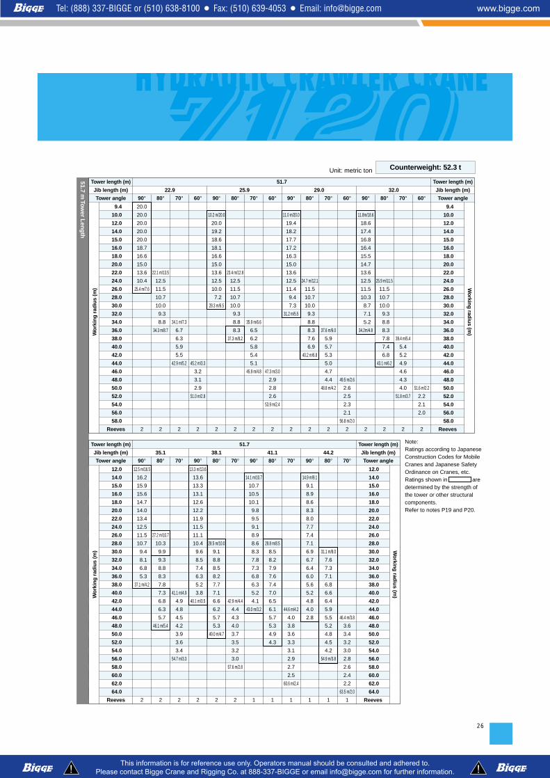
Tower Jib Lifting Capacities
Note: Ratings according to Japanese Construction Codes for Mobile Cranes and Japanese Safety Ordinance on Cranes, etc.Ratings shown in are determined by the strength of the tower or other structural components.Refer to notes P19 and P20.
Unit: metric ton

22
20.0
20.0
20.0
20.0
20.0
18.7
16.6
15.0
13.5
10.1
25.4 m/7.3
2
90°
19.4 m/15.4
15.0
13.6
12.5
11.5
10.7
10.0
31.7 m/9.4
2
80°
28.9 m/10.3
10.0
9.3
8.8
8.3
37.7 m/7.9
2
70°
37.6 m/6.8
6.6
6.2
5.8
43.3m/5.6
2
60°
10.2 m/20.0
20.0
20.0
20.0
18.7
16.6
15.0
13.6
12.4
9.8
6.9
28.3 m/6.3
2
90°
20.7 m/14.4
13.6
12.5
11.5
10.7
10.0
9.3
8.8
34.6 m/8.2
2
80°
30.7 m/9.7
9.3
8.8
8.3
7.8
7.2
40.7 m/7.1
2
70°
39.7 m/6.2
6.0
5.7
5.4
5.0
46.3 m/5.0
2
60°
11.0 m/20.0
20.0
20.0
20.0
18.7
16.6
15.0
13.6
12.5
11.2
9.2
7.1
31.2m/5.4
2
90°
13.6
12.5
11.5
10.7
10.0
9.3
8.8
8.3
37.6 m/7.1
2
80°
32.4 m/9.2
8.7
8.2
7.7
7.2
6.7
43.6m/6.3
2
70°
41.9 m/5.6
5.5
5.2
4.9
4.6
49.2 m/4.4
2
60°
11.8m/20.0
20.0
19.6
19.1
18.6
16.6
15.0
13.6
12.5
11.5
10.2
8.6
6.9
5.0
34.2m/4.6
2
90°
23.3 m/12.8
12.5
11.5
10.7
10.0
9.3
8.8
8.3
7.8
7.0
40.5 m/6.2
2
80°
34.2 m/8.6
8.0
7.6
7.1
6.6
6.2
5.9
46.5 m/5.7
2
70°
5.0
4.7
4.6
4.3
4.0
52.2 m/3.8
2
60°22.9 25.9 29.0
36.5
32.0
9.4
10.0
12.0
14.0
15.0
16.0
18.0
20.0
22.0
24.0
26.0
28.0
30.0
32.0
34.0
36.0
38.0
40.0
42.0
44.0
46.0
48.0
50.0
52.0
54.0
Reeves
9.4
10.0
12.0
14.0
15.0
16.0
18.0
20.0
22.0
24.0
26.0
28.0
30.0
32.0
34.0
36.0
38.0
40.0
42.0
44.0
46.0
48.0
50.0
52.0
54.0
Reeves
Tower angle
Jib length (m)
Tower length (m)
Tower angle
Jib length (m)
Tower length (m)
Wo
rkin
g r
adiu
s (m
) Wo
rking
radiu
s (m)
20.0
20.0
20.0
20.0
20.0
18.7
16.6
15.0
13.6
10.2
25.4 m/7.4
2
90°
15.0
13.6
12.5
11.5
10.7
10.0
9.3
32.2 m/9.3
2
80°
10.0
9.3
8.7
8.1
7.5
38.8 m/7.3
2
70°
39.1 m/6.0
5.7
5.4
5.1
44.9 m/4.8
2
60°
10.2 m/20.0
20.0
20.0
20.0
18.7
16.6
15.0
13.6
12.4
9.8
7.0
28.3 m/6.3
2
90°
21.2 m/14.1
13.6
12.5
11.5
10.7
10.0
9.3
8.8
35.1 m/8.2
2
80°
31.7 m/9.4
9.2
8.6
8.0
7.5
7.0
41.7m/6.5
2
70°
41.2 m/5.3
5.2
5.0
4.7
47.8 m/4.4
2
60°
11.0 m/20.0
20.0
20.0
20.0
18.7
16.6
15.0
13.6
12.5
11.3
9.3
7.2
31.2 m/5.4
2
90°
22.5 m/13.3
12.5
11.5
10.7
10.0
9.3
8.8
8.3
7.5
38.1 m/7.1
2
80°
33.5 m/8.6
8.4
7.9
7.3
6.9
6.4
6.0
44.6 m/5.9
2
70°
43.4 m/4.7
4.7
4.5
4.3
4.0
50.8m/3.9
2
60°
11.8 m/20.0
20.0
19.6
19.1
18.6
16.6
15.0
13.6
12.5
11.5
10.2
8.6
6.9
5.0
34.2 m/4.7
2
90°
23.8 m/12.6
12.5
11.5
10.7
10.0
9.3
8.8
8.3
7.8
7.4
41.0 m/6.2
2
80°
35.2 m/8.0
7.7
7.2
6.8
6.3
6.0
5.6
47.6 m/5.3
2
70°
45.5m/4.3
4.3
4.2
3.9
3.7
53.7 m/3.5
2
60°
12.5 m/16.5
16.3
16.0
15.7
15.3
14.9
13.6
12.5
11.5
10.7
9.4
8.0
6.7
5.2
37.1 m/4.1
2
90°
25.1 m/11.9
11.5
10.7
10.0
9.3
8.8
8.3
7.8
7.5
7.1
5.4
2
80°
36.9m/7.4
7.0
6.7
6.3
5.9
5.5
5.2
4.9
50.5 m/4.8
2
70°
47.7m/4.0
4.0
3.8
3.6
3.4
3.2
56.6 m/3.1
2
60°22.9 25.9 32.029.0
39.5
35.1
9.4
10.0
12.0
14.0
15.0
16.0
18.0
20.0
22.0
24.0
26.0
28.0
30.0
32.0
34.0
36.0
38.0
40.0
42.0
44.0
46.0
48.0
50.0
52.0
54.0
56.0
58.0
Reeves
9.4
10.0
12.0
14.0
15.0
16.0
18.0
20.0
22.0
24.0
26.0
28.0
30.0
32.0
34.0
36.0
38.0
40.0
42.0
44.0
46.0
48.0
50.0
52.0
54.0
56.0
58.0
Reeves
Tower angle
Jib length (m)
Tower length (m)
Tower angle
Jib length (m)
Tower length (m)
Wo
rkin
g r
adiu
s (m
) Wo
rking
radiu
s (m)
39.5 m Tow
er Len
gth
36.5 m Tow
er Len
gth
Counterweight: 52.3 t
Note: Ratings according to Japanese Construction Codes for Mobile Cranes and Japanese Safety Ordinance on Cranes, etc.Ratings shown in are determined by the strength of the tower or other structural components.Refer to notes P19 and P20.
Unit: metric ton

23
20.0
20.0
20.0
20.0
20.0
18.7
16.6
15.0
13.6
10.3
25.4 m/7.5
2
90°
20.5 m/14.6
13.6
12.5
11.5
10.7
10.0
9.3
32.7 m/9.1
2
80°
31.0 m/9.5
9.0
8.4
7.8
7.3
39.8 m/6.8
2
70°
40.6 m/5.2
5.0
4.7
4.4
46.4 m/4.3
2
60°
10.2 m/20.0
20.0
20.0
20.0
18.7
16.6
15.0
13.6
12.5
9.9
7.1
28.3 m/6.4
2
90°
21.8 m/13.7
13.6
12.5
11.5
10.7
10.0
9.3
8.8
35.7 m/8.2
2
80°
32.7 m/8.7
8.2
7.7
7.2
6.7
6.3
42.7 m/6.1
2
70°
42.8 m/4.6
4.5
4.3
4.1
49.3 m/3.9
2
60°
11.0 m/20.0
20.0
20.0
20.0
18.7
16.6
15.0
13.6
12.5
11.3
9.3
7.2
31.2 m/5.5
2
90°
23.1 m/12.9
12.5
11.5
10.7
10.0
9.3
8.8
8.3
7.8
38.6 m/7.1
2
80°
34.5 m/8.0
7.5
7.1
6.6
6.2
5.8
45.7 m/5.4
2
70°
44.9 m/4.2
4.1
3.9
3.7
3.5
52.3 m/3.4
2
60°22.9 25.9 29.0
42.5
Tower angle
Jib length (m)
Tower length (m)
Tower angle
Jib length (m)
Tower length (m)
9.4
10.0
12.0
14.0
15.0
16.0
18.0
20.0
22.0
24.0
26.0
28.0
30.0
32.0
34.0
36.0
38.0
40.0
42.0
44.0
46.0
48.0
50.0
52.0
54.0
Reeves
9.4
10.0
12.0
14.0
15.0
16.0
18.0
20.0
22.0
24.0
26.0
28.0
30.0
32.0
34.0
36.0
38.0
40.0
42.0
44.0
46.0
48.0
50.0
52.0
54.0
Reeves
42.5 m Tow
er Len
gth
Wo
rking
radiu
s (m)W
ork
ing
rad
ius
(m)
11.8 m/20.0
20.0
19.5
19.0
18.5
16.6
15.0
13.6
12.5
11.5
10.3
8.7
7.0
5.1
34.2 m/4.7
2
90°
24.4 m/12.2
11.5
10.7
10.0
9.3
8.8
8.3
7.8
7.5
41.5 m/6.2
2
80°
36.2 m/7.4
6.8
6.5
6.1
5.7
5.4
5.0
48.6 m/4.9
2
70°
47.1 m/3.8
3.7
3.6
3.4
3.2
55.2 m/3.0
2
60°
12.5 m/16.5
16.2
16.0
15.7
15.3
14.8
13.6
12.5
11.5
10.7
9.4
8.0
6.7
5.3
37.1 m/4.1
2
90°
25.6 m/11.7
11.5
10.7
10.0
9.3
8.8
8.3
7.8
7.5
7.1
6.1
44.5 m/5.4
2
80°
6.8
6.4
6.0
5.6
5.3
5.0
4.7
51.6 m/4.4
2
70°
49.2m/3.4
3.4
3.3
3.1
2.9
2.8
58.2 m/2.7
2
60°
13.3 m/13.6
13.6
13.4
13.1
12.7
12.3
11.9
11.6
11.2
10.5
9.6
8.5
7.4
6.3
5.1
3.7
40.1 m/3.5
2
90°
26.9 m/11.1
10.7
10.0
9.3
8.8
8.3
7.8
7.5
7.1
6.7
5.9
47.4 m/4.7
2
80°
39.7 m/6.3
6.1
5.9
5.5
5.2
4.9
4.6
4.3
4.1
54.5 m/3.8
2
70°
51.4 m/3.2
3.1
3.0
2.8
2.6
2.5
61.1 m/2.4
2
60°32.0 35.1 38.1
42.5
Tower angle
Jib length (m)
Tower length (m)
Tower angle
Jib length (m)
Tower length (m)
10.0
12.0
14.0
15.0
16.0
18.0
20.0
22.0
24.0
26.0
28.0
30.0
32.0
34.0
36.0
38.0
40.0
42.0
44.0
46.0
48.0
50.0
52.0
54.0
56.0
58.0
60.0
62.0
Reeves
10.0
12.0
14.0
15.0
16.0
18.0
20.0
22.0
24.0
26.0
28.0
30.0
32.0
34.0
36.0
38.0
40.0
42.0
44.0
46.0
48.0
50.0
52.0
54.0
56.0
58.0
60.0
62.0
Reeves
Wo
rking
radiu
s (m)W
ork
ing
rad
ius
(m)
Counterweight: 52.3 tUnit: metric ton
Note: Ratings according to Japanese Construction Codes for Mobile Cranes and Japanese Safety Ordinance on Cranes, etc.Ratings shown in are determined by the strength of the tower or other structural components.Refer to notes P19 and P20.

24
20.0
20.0
20.0
20.0
20.0
18.7
16.6
15.0
13.6
10.3
25.4 m/7.5
2
90°
21.0 m/14.2
13.6
12.5
11.5
10.7
10.0
9.3
33.2 m/9.0
2
80°
8.7
8.0
7.5
7.0
6.5
40.8 m/6.3
2
70°
42.1 m/4.4
4.3
4.1
47.9 m/3.9
2
60°
10.2 m/20.0
20.0
20.0
20.0
18.7
16.6
15.0
13.6
12.5
9.9
7.1
28.3 m/6.4
2
90°
22.3 m/13.4
12.5
11.5
10.7
10.0
9.3
8.8
8.3
36.2 m/8.2
2
80°
33.8 m/8.0
7.8
7.4
6.9
6.4
6.0
43.8 m/5.6
2
70°
44.3 m/4.0
3.9
3.7
3.5
50.9 m/3.4
2
60°
11.0 m/20.0
20.0
20.0
20.0
18.7
16.6
15.0
13.6
12.5
11.3
9.3
7.2
31.2 m/5.5
2
90°
23.6 m/12.7
12.5
11.5
10.7
10.0
9.3
8.8
8.3
7.8
39.1 m/7.1
2
80°
35.5m/7.4
7.1
6.8
6.3
5.9
5.5
5.2
46.7 m/5.0
2
70°
46.4 m/3.6
3.5
3.4
3.2
53.8 m/3.0
2
60°
11.8m/20.0
20.0
19.5
19.0
18.5
16.6
15.0
13.6
12.5
11.5
10.3
8.7
7.0
5.2
34.2m/4.8
2
90°
24.9 m/12.0
11.5
10.7
10.0
9.3
8.8
8.3
7.8
7.5
6.5
42.1 m/6.2
2
80°
37.3 m/6.8
6.5
6.2
5.8
5.5
5.1
4.8
49.7 m/4.4
2
70°
48.6 m/3.3
3.2
3.1
2.9
2.7
56.7 m/2.6
2
60°22.9 25.9 29.0
45.6
32.0
9.4
10.0
12.0
14.0
15.0
16.0
18.0
20.0
22.0
24.0
26.0
28.0
30.0
32.0
34.0
36.0
38.0
40.0
42.0
44.0
46.0
48.0
50.0
52.0
54.0
56.0
58.0
Reeves
9.4
10.0
12.0
14.0
15.0
16.0
18.0
20.0
22.0
24.0
26.0
28.0
30.0
32.0
34.0
36.0
38.0
40.0
42.0
44.0
46.0
48.0
50.0
52.0
54.0
56.0
58.0
Reeves
Tower angle
Jib length (m)
Tower length (m)
Tower angle
Jib length (m)
Tower length (m)
Wo
rkin
g r
adiu
s (m
) Wo
rking
radiu
s (m)
45.6 m Tow
er Len
gth
12.5 m/16.5
16.2
16.0
15.7
15.2
14.8
13.6
12.5
11.5
10.7
9.4
8.1
6.7
5.3
37.1 m/4.1
2
90°
26.2 m/11.4
10.7
10.0
9.3
8.8
8.3
7.8
7.5
7.1
6.8
45.0 m/5.4
2
80°
39.0 m/6.3
6.0
5.7
5.4
5.1
4.8
4.5
4.2
52.6 m/3.9
2
70°
50.7 m/3.0
2.9
2.8
2.7
2.5
59.7 m/2.3
2
60°13.3 m/13.6
13.6
13.3
13.1
12.7
12.3
11.9
11.6
11.1
10.5
9.6
8.5
7.4
6.3
5.1
3.8
40.1 m/3.5
2
90°
27.5 m/10.9
10.7
10.0
9.3
8.8
8.3
7.8
7.5
7.1
6.7
6.2
4.7
2
80°
40.8 m/5.7
5.4
5.2
4.9
4.6
4.4
4.1
3.9
55.6 m/3.4
2
70°
52.9 m/2.7
2.6
2.5
2.4
2.2
2.1
62.6 m/2.0
2
60°
14.1 m/10.7
10.7
10.5
10.2
9.8
9.5
9.2
8.9
8.6
8.3
7.8
7.3
6.8
6.2
5.2
4.1
43.0 m/3.2
2
90°
28.7 m/9.8
9.6
9.3
8.8
8.3
7.8
7.5
7.1
6.6
6.2
5.8
5.2
50.9 m/4.3
2
80°
42.5 m/5.4
5.0
4.8
4.5
4.3
4.0
3.8
3.5
3.3
58.5 m/3.1
2
70°35.1 38.1 41.1
45.6
12.0
14.0
15.0
16.0
18.0
20.0
22.0
24.0
26.0
28.0
30.0
32.0
34.0
36.0
38.0
40.0
42.0
44.0
46.0
48.0
50.0
52.0
54.0
56.0
58.0
60.0
62.0
64.0
Reeves
12.0
14.0
15.0
16.0
18.0
20.0
22.0
24.0
26.0
28.0
30.0
32.0
34.0
36.0
38.0
40.0
42.0
44.0
46.0
48.0
50.0
52.0
54.0
56.0
58.0
60.0
62.0
64.0
Reeves
Tower angle
Jib length (m)
Tower length (m)
Tower angle
Jib length (m)
Tower length (m)
Wo
rkin
g r
adiu
s (m
) Wo
rking
radiu
s (m)
Counterweight: 52.3 tUnit: metric ton
Note: Ratings according to JapaneseConstruction Codes for MobileCranes and Japanese SafetyOrdinance on Cranes, etc.Ratings shown in aredetermined by the strength of thetower or other structural compo-nents.Refer to notes P19 and P20.

25
20.0
20.0
20.0
20.0
20.0
18.7
16.6
15.0
13.6
10.4
25.4 m/7.5
2
90°
21.5 m/13.9
13.6
12.5
11.5
10.7
10.0
9.3
33.8 m/8.8
2
80°
33.1 m/8.0
7.6
7.2
6.7
6.3
41.9 m/5.8
2
70°
43.7 m/3.8
3.8
3.7
3.4
49.4 m/3.1
2
60°
10.2 m/20.0
20.0
20.0
19.8
18.7
16.6
15.0
13.6
12.5
10.0
7.1
28.3 m/6.4
2
90°
22.8 m/13.1
12.5
11.5
10.7
10.0
9.3
8.8
8.3
36.7 m/8.1
2
80°
34.8 m/7.4
6.9
6.6
6.2
5.8
5.4
44.8 m/5.2
2
70°
45.8 m/3.4
3.4
3.3
3.1
2.9
52.4 m/2.8
2
60°
11.0 m/20.0
20.0
19.5
18.9
18.3
16.6
15.0
13.6
12.5
11.4
9.4
7.3
31.2 m/5.5
2
90°
24.1 m/12.4
11.5
10.7
10.0
9.3
8.8
8.3
7.8
39.7 m/7.1
2
80°
36.6 m/6.8
6.3
6.0
5.6
5.3
5.0
47.8 m/4.5
2
70°
3.1
3.0
2.8
2.6
55.3 m/2.4
2
60°
11.8m/19.9
19.9
18.6
18.0
17.5
16.5
15.0
13.6
12.5
11.5
10.3
8.7
7.1
5.2
34.2m/4.8
2
90°
25.4m/11.8
11.5
10.7
10.0
9.3
8.8
8.3
7.8
7.3
6.7
42.6 m/6.2
2
80°
38.3 m/6.2
5.8
5.5
5.2
4.9
4.6
4.3
50.7 m/4.0
2
70°
50.1 m/2.7
2.6
2.5
2.4
2.2
58.3 m/2.1
2
60°22.9 25.9 29.0
48.6
32.0
9.4
10.0
12.0
14.0
15.0
16.0
18.0
20.0
22.0
24.0
26.0
28.0
30.0
32.0
34.0
36.0
38.0
40.0
42.0
44.0
46.0
48.0
50.0
52.0
54.0
56.0
58.0
60.0
Reeves
9.4
10.0
12.0
14.0
15.0
16.0
18.0
20.0
22.0
24.0
26.0
28.0
30.0
32.0
34.0
36.0
38.0
40.0
42.0
44.0
46.0
48.0
50.0
52.0
54.0
56.0
58.0
60.0
Reeves
Tower angle
Jib length (m)
Tower length (m)
Tower angle
Jib length (m)
Tower length (m)
Wo
rkin
g r
adiu
s (m
) Wo
rking
radiu
s (m)
48.6 m Tow
er Len
gth
12.5 m/16.5
16.2
15.9
15.7
15.2
14.8
13.6
12.5
11.5
10.7
9.4
8.1
6.7
5.3
37.1 m/4.1
2
90°
26.7 m/11.2
10.7
10.0
9.3
8.8
8.3
7.8
7.5
7.1
6.5
45.6 m/5.4
2
80°
40.1 m/5.7
5.3
5.1
4.8
4.5
4.2
4.0
53.7 m/3.5
2
70°
52.3 m/2.4
2.3
2.2
2.1
2.0
2
60°13.3 m/13.6
13.6
13.3
13.1
12.7
12.3
11.9
11.5
11.1
10.5
9.6
8.5
7.4
6.3
5.1
3.8
40.1 m/3.5
2
90°
10.7
10.0
9.3
8.8
8.3
7.8
7.5
6.9
6.5
6.0
5.5
48.5 m/4.7
2
80°
41.8 m/5.2
5.2
5.0
4.7
4.4
4.1
3.8
3.6
3.4
56.6 m/3.3
2
70°
14.1 m/10.7
10.7
10.5
10.1
9.8
9.5
9.2
8.9
8.6
8.3
7.8
7.3
6.8
6.2
5.2
4.1
43.0 m/3.2
2
90°
29.3 m/9.8
9.6
9.2
8.8
8.3
7.8
7.3
6.8
6.4
5.9
5.5
5.1
51.4 m/4.3
2
80°
43.6 m/4.8
4.7
4.6
4.3
4.0
3.7
3.5
3.3
3.0
59.6 m/2.8
2
70°
14.9 m/9.1
9.1
8.9
8.6
8.3
8.0
7.7
7.4
7.2
6.9
6.7
6.4
6.0
5.6
5.2
4.8
4.0
2.8
2
90°
30.6 m/8.0
7.8
7.6
7.3
7.1
6.9
6.7
6.2
5.8
5.5
5.1
4.7
4.3
54.4 m/3.8
2
80°
45.3 m/4.4
4.3
4.1
3.9
3.6
3.4
3.1
2.9
2.7
2.5
62.5 m/2.4
2
70°35.1 38.1 41.1
48.6
44.2
12.0
14.0
15.0
16.0
18.0
20.0
22.0
24.0
26.0
28.0
30.0
32.0
34.0
36.0
38.0
40.0
42.0
44.0
46.0
48.0
50.0
52.0
54.0
56.0
58.0
60.0
62.0
64.0
Reeves
12.0
14.0
15.0
16.0
18.0
20.0
22.0
24.0
26.0
28.0
30.0
32.0
34.0
36.0
38.0
40.0
42.0
44.0
46.0
48.0
50.0
52.0
54.0
56.0
58.0
60.0
62.0
64.0
Reeves
Tower angle
Jib length (m)
Tower length (m)
Tower angle
Jib length (m)
Tower length (m)
Wo
rkin
g r
adiu
s (m
) Wo
rking
radiu
s (m)
Counterweight: 52.3 tUnit: metric ton
Note: Ratings according toJapanese ConstructionCodes for Mobile Cranesand Japanese SafetyOrdinance on Cranes, etc.Ratings shown inare determined by thestrength of the tower orother structural compo-nents.Refer to notes P19 andP20.
20.0
20.0
20.0
20.0
20.0
18.7
16.6
15.0
13.6
10.4
25.4 m/7.6
2
90°
22.1 m/13.5
12.5
11.5
10.7
10.0
9.3
8.8
34.3 m/8.7
2
80°
34.1 m/7.3
6.7
6.3
5.9
5.5
42.9 m/5.2
2
70°
45.2 m/3.3
3.2
3.1
2.9
51.0 m/2.8
2
60°
10.2 m/20.0
20.0
19.2
18.6
18.1
16.6
15.0
13.6
12.5
10.0
7.2
28.3 m/6.5
2
90°
23.4 m/12.8
12.5
11.5
10.7
10.0
9.3
8.8
8.3
37.3 m/8.2
2
80°
35.9 m/6.6
6.5
6.2
5.8
5.4
5.1
45.9 m/4.8
2
70°
47.3 m/3.0
2.9
2.8
2.6
53.9 m/2.4
2
60°
11.0 m/20.0
19.4
18.2
17.7
17.2
16.3
15.0
13.6
12.5
11.4
9.4
7.3
31.2 m/5.5
2
90°
24.7 m/12.1
11.5
10.7
10.0
9.3
8.8
8.3
7.6
6.9
40.2 m/6.8
2
80°
37.6 m/6.0
5.9
5.7
5.3
5.0
4.7
4.4
48.8 m/4.2
2
70°
49.5 m/2.6
2.6
2.5
2.3
2.1
56.8 m/2.0
2
60°
11.8m/18.6
18.6
17.4
16.8
16.4
15.5
14.7
13.6
12.5
11.5
10.3
8.7
7.1
5.2
34.2m/4.8
2
90°
25.9 m/11.5
11.5
10.7
10.0
9.3
8.8
8.3
7.8
7.4
6.8
43.1 m/6.2
2
80°
39.4 m/5.4
5.4
5.2
4.9
4.6
4.3
4.0
51.8 m/3.7
2
70°
51.6 m/2.2
2.2
2.1
2.0
2
60°22.9 25.9 29.0
51.7
32.0
9.4
10.0
12.0
14.0
15.0
16.0
18.0
20.0
22.0
24.0
26.0
28.0
30.0
32.0
34.0
36.0
38.0
40.0
42.0
44.0
46.0
48.0
50.0
52.0
54.0
56.0
58.0
Reeves
9.4
10.0
12.0
14.0
15.0
16.0
18.0
20.0
22.0
24.0
26.0
28.0
30.0
32.0
34.0
36.0
38.0
40.0
42.0
44.0
46.0
48.0
50.0
52.0
54.0
56.0
58.0
Reeves
Tower angle
Jib length (m)
Tower length (m)
Tower angle
Jib length (m)
Tower length (m)
Wo
rkin
g r
adiu
s (m
) Wo
rking
radiu
s (m)
51.7 m Tow
er Len
gth
12.5 m/16.5
16.2
15.9
15.6
14.7
14.0
13.4
12.5
11.5
10.7
9.4
8.1
6.8
5.3
37.1 m/4.2
2
90°
27.2 m/10.7
10.3
9.9
9.3
8.8
8.3
7.8
7.3
6.8
6.3
5.7
46.1 m/5.4
2
80°
41.1 m/4.9
4.9
4.8
4.5
4.2
3.9
3.6
3.4
54.7 m/3.3
2
70°13.3 m/13.6
13.6
13.3
13.1
12.6
12.2
11.9
11.5
11.1
10.4
9.6
8.5
7.4
6.3
5.2
3.8
40.1 m/3.5
2
90°
28.5 m/10.0
9.1
8.8
8.5
8.2
7.7
7.1
6.6
6.2
5.7
5.3
49.0 m/4.7
2
80°
42.9 m/4.4
4.4
4.3
4.0
3.7
3.5
3.2
3.0
57.6 m/2.8
2
70°
14.1 m/10.7
10.7
10.5
10.1
9.8
9.5
9.1
8.9
8.6
8.3
7.8
7.3
6.8
6.3
5.2
4.1
43.0 m/3.2
1
90°
29.8 m/8.5
8.5
8.2
7.9
7.6
7.4
7.0
6.5
6.1
5.7
5.3
4.9
4.3
1
80°
44.6 m/4.2
4.0
3.8
3.6
3.3
3.1
2.9
2.7
2.5
60.6 m/2.4
1
70°
14.9 m/9.1
9.1
8.9
8.6
8.3
8.0
7.7
7.4
7.1
6.9
6.7
6.4
6.0
5.6
5.2
4.8
4.0
2.8
1
90°
31.1 m/8.0
7.6
7.3
7.1
6.8
6.6
6.4
5.9
5.5
5.2
4.8
4.5
4.2
54.9 m/3.8
1
80°
46.4 m/3.8
3.6
3.4
3.2
3.0
2.8
2.6
2.4
2.2
63.5 m/2.0
1
70°35.1 38.1 41.1
51.7
44.2
12.0
14.0
15.0
16.0
18.0
20.0
22.0
24.0
26.0
28.0
30.0
32.0
34.0
36.0
38.0
40.0
42.0
44.0
46.0
48.0
50.0
52.0
54.0
56.0
58.0
60.0
62.0
64.0
Reeves
12.0
14.0
15.0
16.0
18.0
20.0
22.0
24.0
26.0
28.0
30.0
32.0
34.0
36.0
38.0
40.0
42.0
44.0
46.0
48.0
50.0
52.0
54.0
56.0
58.0
60.0
62.0
64.0
Reeves
Tower angle
Jib length (m)
Tower length (m)
Tower angle
Jib length (m)
Tower length (m)
Wo
rkin
g r
adiu
s (m
) Wo
rking
radiu
s (m)
26
Counterweight: 52.3 tUnit: metric ton
Note: Ratings according to JapaneseConstruction Codes for MobileCranes and Japanese SafetyOrdinance on Cranes, etc.Ratings shown in aredetermined by the strength ofthe tower or other structuralcomponents.Refer to notes P19 and P20.
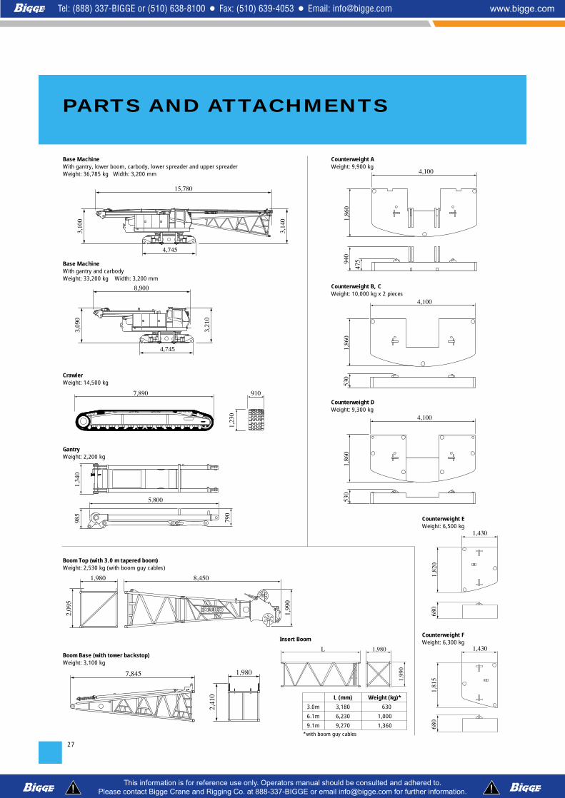
27
PARTS AND ATTACHMENTS
CrawlerWeight: 14,500 kg
7,890 910
1,230
GantryWeight: 2,200 kg
5,800
985
1,340
790
Boom Base (with tower backstop)Weight: 3,100 kg
7,845 1,980
2,410
Base MachineWith gantry, lower boom, carbody, lower spreader and upper spreaderWeight: 36,785 kg Width: 3,200 mm
3,140
4,745
15,780
3,100
Base MachineWith gantry and carbodyWeight: 33,200 kg Width: 3,200 mm
3,21
0
4,745
8,900
3,09
0
Boom Top (with 3.0 m tapered boom)Weight: 2,530 kg (with boom guy cables)
8,4501,980
2,095
1,990
Insert Boom
L 1,980
1,990
475
4,100
1,860
940
Counterweight AWeight: 9,900 kg
1,430
680
1,820
Counterweight EWeight: 6,500 kg
1,430
680
1,815
Counterweight FWeight: 6,300 kg
4,100
1,860
530
Counterweight B, CWeight: 10,000 kg x 2 pieces
4,100
1,860
530
Counterweight DWeight: 9,300 kg
L (mm) Weight (kg)*
3.0m 3,180 630
6.1m 6,230 1,000
9.1m 9,270 1,360*with boom guy cables

28
Dimensions: mm Weight: kg
Jib Top (For Crane) Weight: 315 kg
5,040
840
1,020
Jib Base (For Crane)Weight: 210 kg
4,760
840
1,020
1,030
Tower Jib BaseWeight: 1,200 kg
6,395
2,020
1,530
1,365
Tower CapWeight: 1,780 kg
4,875 1,990
2,065
Tower Jib TopWeight: 900 kg
8,1501,355
1,365
Attachments Weight Dimensions (L x W x H)9.1A special insert boom for tower 1,740 kg (with guy cables) 9,270 mm x 1,980 mm x 2,790 mm
9.1 m tower insert jib3.0 m insert jib (for crane)6.1 m insert jib (for crane)
Crane backstop
120-ton hook
Tower backstopUpper spreaderLower spreader
Lower spreader for tower jib
3.0 m tower insert jib 210 kg
510 kg110 kg190 kg
210 kg (1 piece)
1,700 kg
420 kg (1 piece)485 kg315 kg
410 kg
360 kg3,145 mm x 1,355 mm x 1,365 mm
3.0A relay jib 230 kg 3,145 mm x 1,530 mm x 1,365 mm
9,240 mm x 1,355 mm x 1,365 mm3,130 mm x 1,020 mm x 840 mm6,175 mm x 1,020 mm x 840 mm
6,265 mm x 115 mm dia. x 210 mm
710 mm x 700 mm x 1,930 mm
35-ton hook 900 kg 365 mm x 700 mm x 1,575 mm
6,200 mm x 140 mm dia. x 235 mm2,045 mm x 365 mm x 880 mm1,150 mm x 300 mm x 930 mm
Upper spreader for tower jib 310 kg 925 mm x 730 mm x 1,170 mm1,940 mm x 460 mm x 1,070 mm
70-ton hook 1,200 kg 470 mm x 700 mm x 1,825 mm
Ball hook 450 kg 380 mm dia. x 1,200 mm
6,195 mm x 1,355 mm x 1,365 mm6.1 m tower insert jib
1,355 kg 5,925 mm x 2,065 mm x 915 mmTower jib strut300 kg 5,130 mm x 1,040 mm x 615 mmCrane jib strut
Note: Estimated weights may vary ± 2%.
Other Attachments

29

30
Standard Equipment
KOBELCO is the corporate mark used by Kobe Steel on a variety of productsand in the names of a number of Kobe Steel Group companies.
17-1, Higashigotanda 2-chome, Shinagawa-ku, Tokyo 141-8626 JAPANTel: +81-3-5789-2130 Fax: +81-3-5789-3372
Bulletin No. 7120-1FSPEC-AO2 080201IF Printed in Japan
HYDRAULIC CRAWLER CRANE
Counterweight: 52.3 ton (total weight)910 mm shoe crawlersBatteries (2-12V, 136 Ah/5HR)Trans-lifter (jack system)Travel kitGantry raising/lowering cylinder Electric hand throttle gripVariable boom hoist speed controllerVariable main/aux. hoist speed controllerSwing neutral-free/brake select switchSide deck for cabSteps (crawlers)Two front working lightsTwo rear view mirrorsTools (for routine maintenance)Upper spreader storage guide
Upper structure/Lower structure
Air conditionerLuggage box Cup holderAshtrayCigar lighterIntermittent wiper & window washer (skylight and front window)Sun visorRoof blindFloor mat (cloth)Foot restShoe tray
Cab/Control
Safety Device
Load Moment Indicator (with boom lowering slow stop function)LMI release key (for hook over-hoist prevention device and boom over-hoist prevention device) LCD multi displayUltimate stop function for boom over-hoistFunction lock leverPropel lever lockMechanical drum lock pawl (main, aux. and boom hoist)Signal hornSwing parking brakeMechanical swing lock pin (four positions)Swing flashers/warning buzzer
Inquiries To:
Note: Standard equipment may vary depending on your areas or countries.Due to our policy of continual product improvements all designs and specifications are subject to change without advance notice.Copyright by KOBELCO CRANES CO., LTD. No part of this catalog may be reproduced in any manner without notice.