
Hydraulic Control Valves - Report
19
HYDRAULIC CONTROL VALVES “report” Represented by: 1. Ahmed Soliman Abdeldayem sec.1 2. Ahmed Rabeie Ahmed sec.1 3. Ahmed Mosatafa Hafez sec.2 4. Khaled Mohammed Awad sec.4 5. Osman Assem Osman sec.6 Submitted To:
-
Upload
ahmed-soliman -
Category
Documents
-
view
307 -
download
7
Transcript of Hydraulic Control Valves - Report
HYDRAULIC CONTROL VALVES
“report”
Represented by:
1. Ahmed Soliman Abdeldayem sec.12. Ahmed Rabeie Ahmed sec.13. Ahmed Mosatafa Hafez sec.24. Khaled Mohammed Awad sec.45. Osman Assem Osman sec.6
Submitted To:
Dr. Ahmed Magid
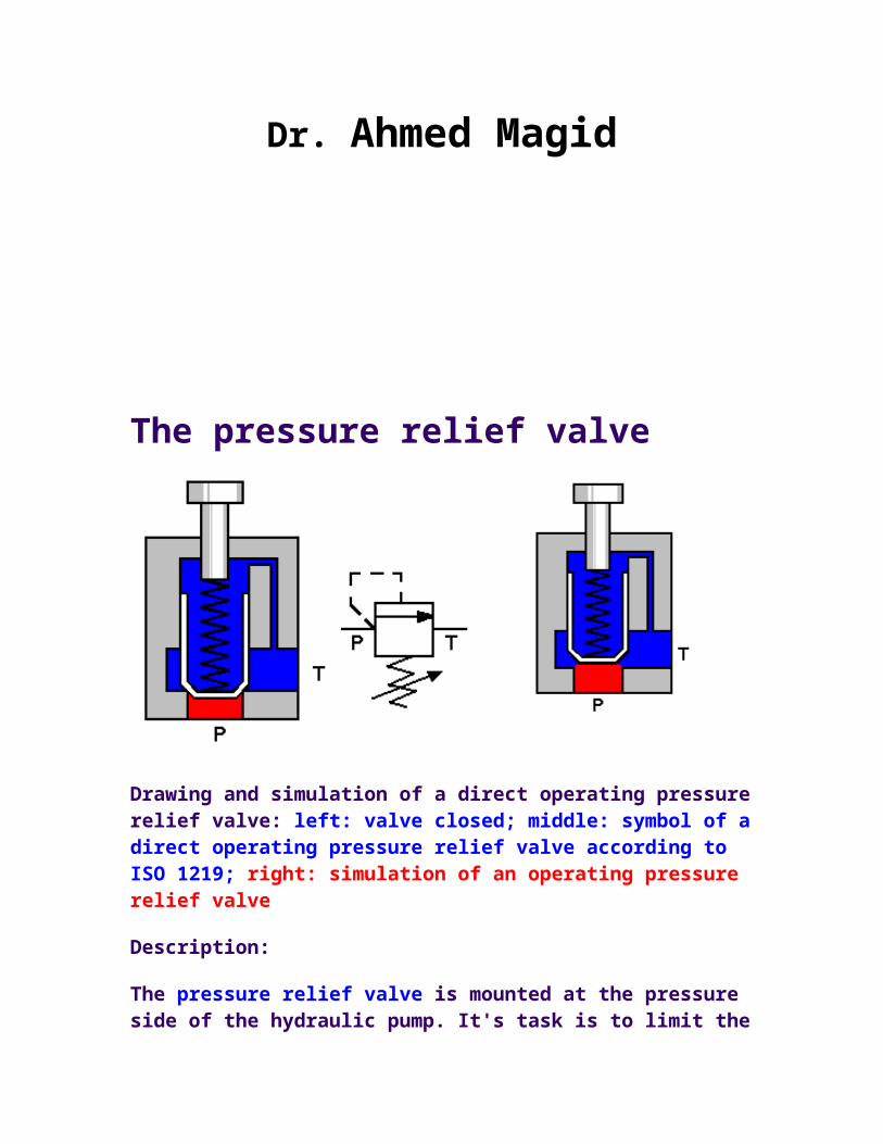
The pressure relief valve
Drawing and simulation of a direct operating pressure relief valve: left: valve closed; middle: symbol of a direct operating pressure relief valve according to ISO 1219; right: simulation of an operating pressure relief valve
Description:
The pressure relief valve is mounted at the pressure side of the hydraulic pump. It's task is to limit the pressure in the system on an acceptable value. In fact a pressure relief valve has the same construction as a spring operated check valve. When the system gets overloaded the pressure relief valve will open and the pump flow will be leaded directly into the hydraulic reservoir. The pressure in the system remains on the value determined by the spring on the pressure relief valve! In the pressure relief valve the pressure (=energy) will be converted into heat. For that reason longtime operation of the pressure relief valve should be avoided.
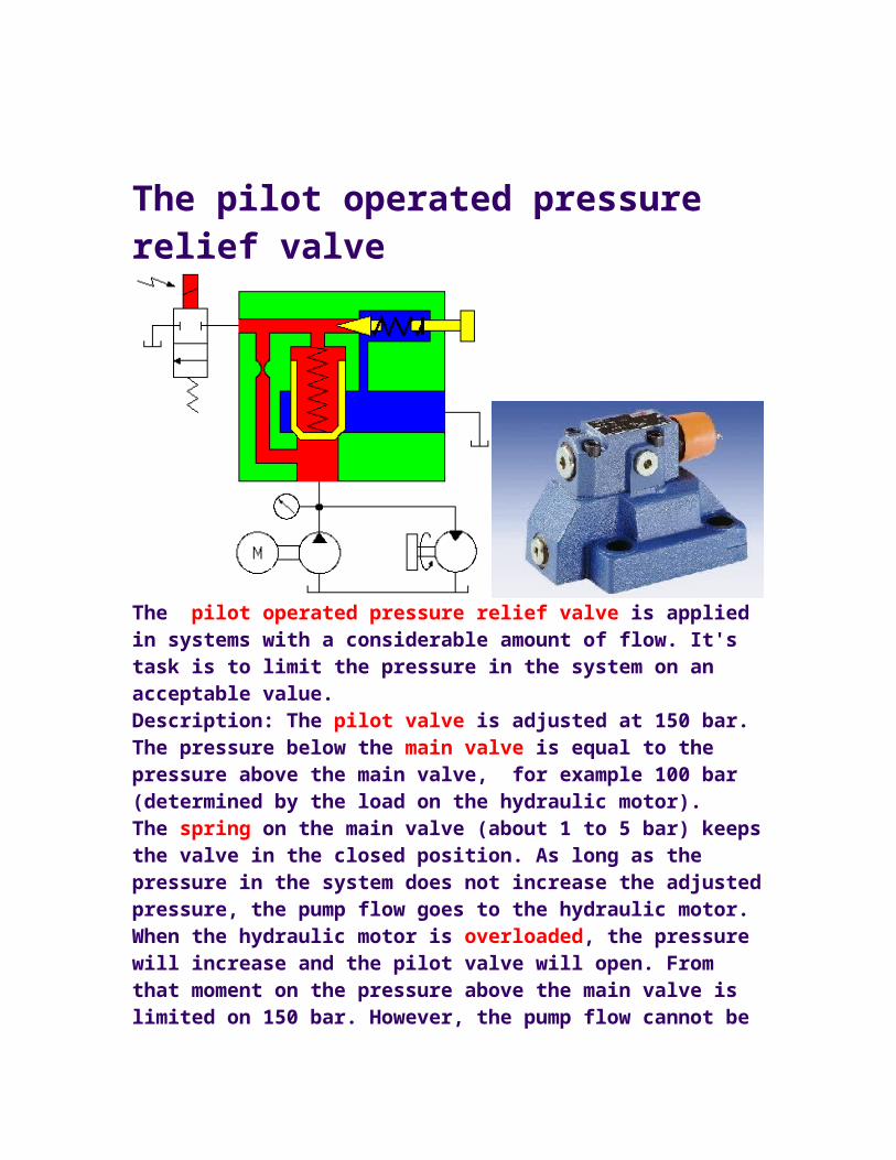
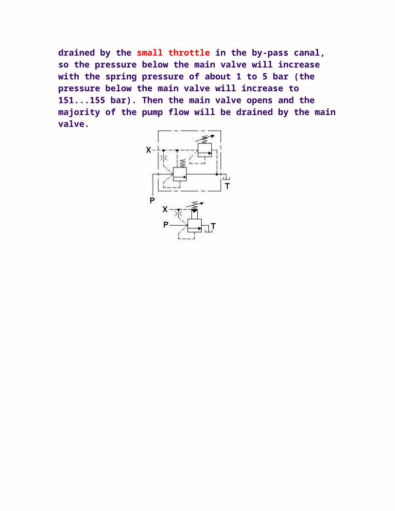
The pilot operated pressure relief valve
The pilot operated pressure relief valve is applied in systems with a considerable amount of flow. It's task is to limit the pressure in the system on an acceptable value. Description: The pilot valve is adjusted at 150 bar. The pressure below the main valve is equal to the pressure above the main valve, for example 100 bar (determined by the load on the hydraulic motor). The spring on the main valve (about 1 to 5 bar) keeps the valve in the closed position. As long as the pressure in the system does not increase the adjusted pressure, the pump flow goes to the hydraulic motor. When the hydraulic motor is overloaded, the pressure will increase and the pilot valve will open. From that moment on the pressure above the main valve is limited on 150 bar. However, the pump flow cannot be drained by the small throttle in the by-pass canal, so the pressure below the main valve will increase with the spring pressure of about 1 to 5 bar (the pressure below the main valve will increase to 151...155 bar). Then the main valve opens and the majority of the pump flow will be drained by the main valve.
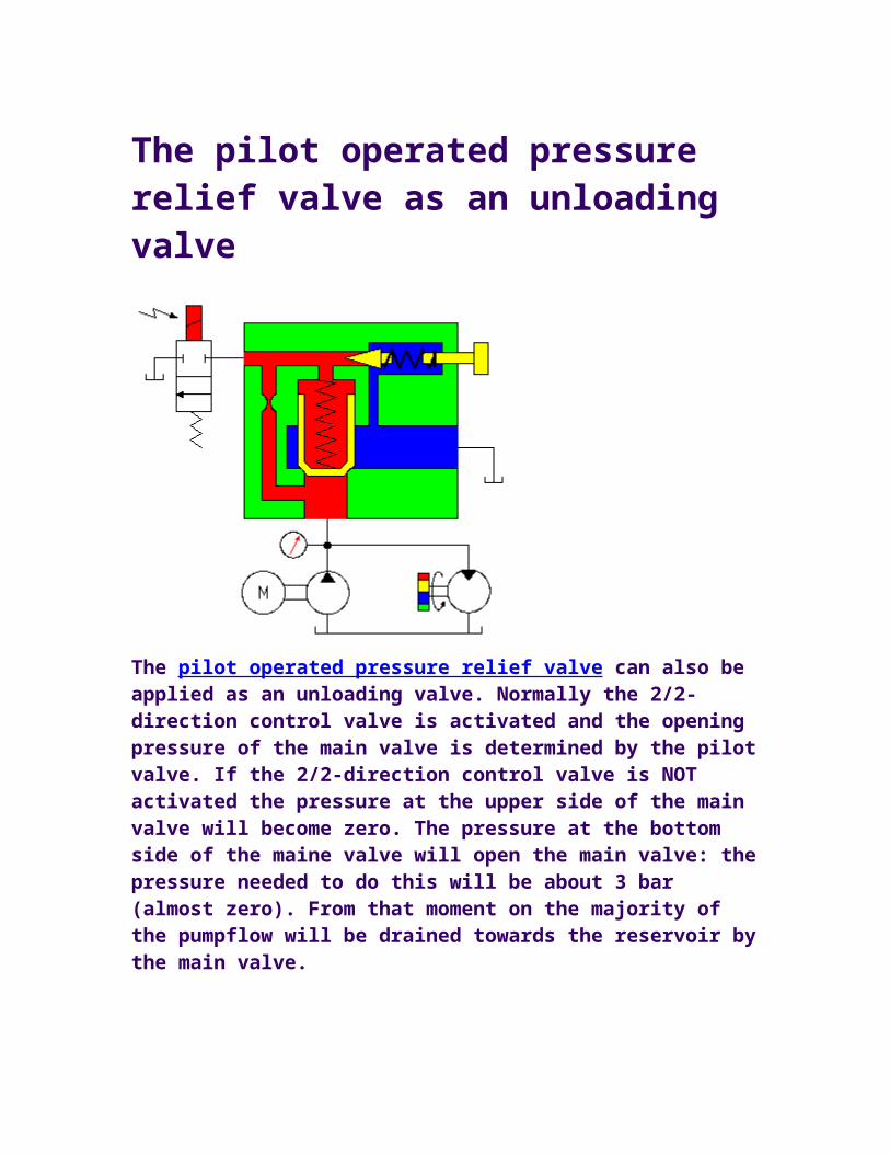
The pilot operated pressure relief valve as an unloading valve
The pilot operated pressure relief valve can also be applied as an unloading valve. Normally the 2/2-direction control valve is activated and the opening pressure of the main valve is determined by the pilot valve. If the 2/2-direction control valve is NOT activated the pressure at the upper side of the main valve will become zero. The pressure at the bottom side of the maine valve will open the main valve: the pressure needed to do this will be about 3 bar (almost zero). From that moment on the majority of the pumpflow will be drained towards the reservoir by the main valve.
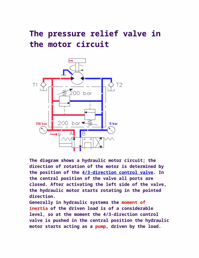
The pressure relief valve in the motor circuit
The diagram shows a hydraulic motor circuit; the direction of rotation of the motor is determined by the position of the 4/3-direction control valve. In the central position of the valve all ports are closed. After activating the left side of the valve, the hydraulic motor starts rotating in the pointed direction. Generally in hydraulic systems the moment of inertia of the driven load is of a considerable level, so at the moment the 4/3-direction control valve is pushed in the central position the hydraulic motor starts acting as a pump, driven by the load. This will cause a tremendous increase of pressure at the right side of the hydraulic 'motor' and if there was no safety valve, the weakest component would break down or explode! In this system however the pressure relief valve will open and the oil flows back to the left side of the hydraulic motor. Because of the pressure at the right side of the motor the speed of rotation decreases to 0 rpm.The hydraulic motor has an external leakage line so there will disappear
oil from the motorcircuit. This may cause cavitation at the left side of the motor. In this system however the circuit is protected against cavitation by the check valves (suction valves). The diagram on this page forms a basic diagram for most motor circuits.
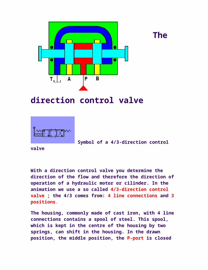
The
direction control valve
Symbol of a 4/3-direction control valve
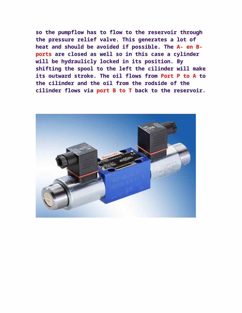
With a direction control valve you determine the direction of the flow and therefore the direction of operation of a hydraulic motor or cilinder. In the animation we use a so called 4/3-direction control valve ; the 4/3 comes from: 4 line connections and 3 positions.
The housing, commonly made of cast iron, with 4 line connections contains a spool of steel. This spool, which is kept in the centre of the housing by two springs, can shift in the housing. In the drawn position, the middle position, the P-port is closed so the pumpflow has to flow to the reservoir through the pressure relief valve. This generates a lot of heat and should be avoided if possible. The A- en B-ports are closed as well so in this case a cylinder will be hydraulicly locked in its position. By shifting the spool to the left the cilinder will make its outward stroke. The oil flows from Port P to A to the cilinder and the oil from the rodside of the cilinder flows via port B to T back to the reservoir.

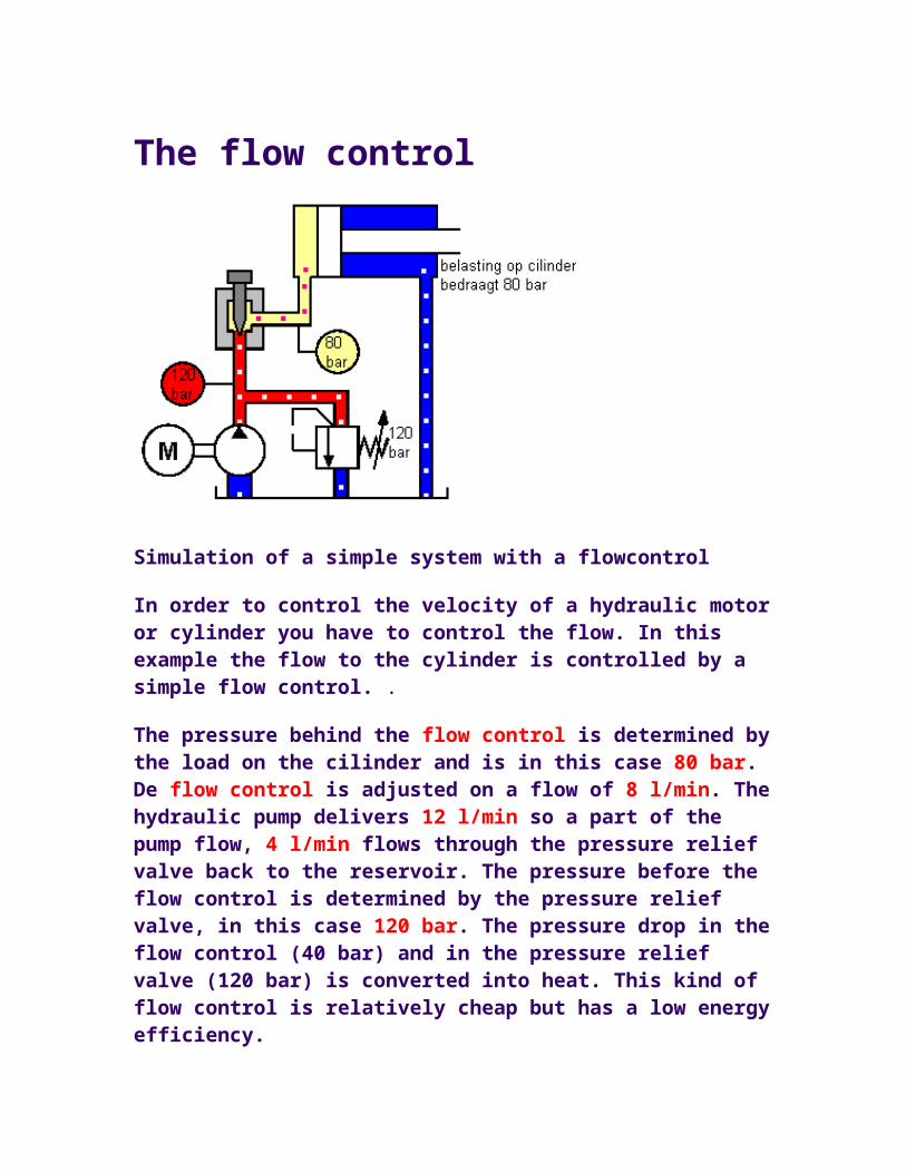
The flow control
Simulation of a simple system with a flowcontrol
In order to control the velocity of a hydraulic motor or cylinder you have to control the flow. In this example the flow to the cylinder is controlled by a simple flow control. .
The pressure behind the flow control is determined by the load on the cilinder and is in this case 80 bar. De flow control is adjusted on a flow of 8 l/min. The hydraulic pump delivers 12 l/min so a part of the pump flow, 4 l/min flows through the pressure relief valve back to the reservoir. The pressure before the flow control is determined by the pressure relief valve, in this case 120 bar. The pressure drop in the flow control (40 bar) and in the pressure relief valve (120 bar) is converted into heat. This kind of flow control is relatively cheap but has a low energy efficiency.
The pressure compensated flow control
Controlling the velocity of a hydraulic cylinder by controlling the flow with a pressure compensated flow control
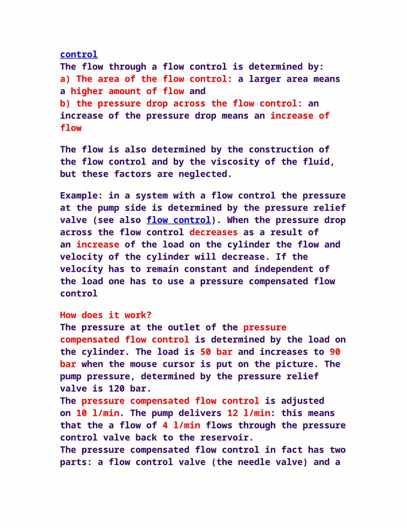
To control the velocity of a hydraulic motor or cylinder one has to control the flow to these components. This can be done with a simple flow controlThe flow through a flow control is determined by:a) The area of the flow control: a larger area means a higher amount of flow andb) the pressure drop across the flow control: an increase of the pressure drop means an increase of flow
The flow is also determined by the construction of the flow control and by the viscosity of the fluid, but these factors are neglected.
Example: in a system with a flow control the pressure at the pump side is determined by the pressure relief valve (see also flow control). When the pressure drop across the flow control decreases as a result of an increase of the load on the cylinder the flow and velocity of the cylinder will decrease. If the velocity has to remain constant and independent of the load one has to use a pressure compensated flow control
How does it work? The pressure at the outlet of the pressure compensated flow control is determined by the load on the cylinder. The load is 50 bar and increases to 90 bar when the mouse cursor is put on the picture. The pump pressure, determined by the pressure relief valve is 120 bar.The pressure compensated flow control is adjusted on 10 l/min. The pump delivers 12 l/min: this means that the a flow of 4 l/min flows through the pressure control valve back to the reservoir. The pressure compensated flow control in fact has two parts: a flow control valve (the needle valve) and a pressure reducing valve or pressure compensator. The desired flow is adjusted with the needle valve. The pressure compensator with spring loaded plunger at the left side measures the pressure at the inlet of the needle valve (p2). At the right side of the plunger the pressure of the load (p3) and of the spring are pushing the plunger to the left. The pressure of the spring is 8 bar. The plunger finds it's balance when:p2 = p3 + pspring ==> p2 - p3 = pspring and because of the fact that pspring= constant (8 bar) the pressure compensator keeps the pressure drop across the needle valve on a constant value of 8 bar. This means that the flow through the needle valve remains constant! When the load increases the pressure p3 increases and the plunger is out of balance and pushed to the left. Then the pressure p2 will increase as well and the plunger finds it's balance again. The pressure drop across the needle valve is still 8 bar so the flow remains 10 l/min and therefore the velocity of the cylinder remains constant and independent of the load!!

The pilot operated check valve
Picture of a pilot operated checkvalve; at the right: application of a pilot operated checkvalve on the cilinder of the outrigger legs of a crane
A pilot operated checkvalve is used to keep a part of the system free from internal leakage for example a hydraulic cilinder or motor. A very good example is the application of the pilot operated checkvalve on the cilinder of the outrigger legs of a crane. The cilinder is connected to port B of the checkvalve. When oil is supplied to port A the oil can flow freely towards port B and to the
cilinder. When the leg has to be retracted oil is supplied to te rodside of the cilinder. The pressure at the rodside of the cilinder is used as pilot pressure on port Z for opening the checkvalve. Now the oil can flow back from port B to port A. The pressure at port Zneeded to open the checkvalve against the cilinderpressure behind the main valve is about 1/3 to 1/10 (called the opening ratio) of the cilinderpressure.

The counterbalance valve
Cross section of a counterbalance valve
In fact a counterbalance valve is an improved pilot operated checkvalve . An important and major difference between these two valves is:- the opening pressure of a pilot operated checkvalve depends on the pressure (applied by the load) behind the valve;- the opening pressure of a counterbalance valve depends on the spring pressure behind the valve.The dynamic performance of a balance valve is many times better than the dynamic performance of a pilot operated check valve
The balancevalve is applied as a 'brake valve' on relatively small crane systems in order to get a positive control on a hydraulic cylinder or motor with a negative load.Functioning (see diagram): When the left side of the 4/3-direction control valve is activated the cylinder will make its 'OUT-stroke'. The oil flows through the checkvalve which is integrated in the housing of the balancevalve. In order to lower the cylinder, the right side of the 4/3-direction control valve has to be activated. From that moment on pressure is built up at the rod side of the cylinder. This pressure opens the balancevalve and the oil at the
bottom side of the cylinder flows through the balancevalve and the direction control valve back to the reservoir.
As the load helps lowering the cylinder, the cylinder might go down faster than the oil is applied to the rod side of the cylinder (the cylinder isn't under control at that moment). However, the pressure at the rod side of the cylinder and therefore the pilot pressure on the balancevalve will decrease and the spring moves the balancevalve to the direction 'close' as long as it finds a new 'balance'.
When the direction control valve is suddenly put in the middle position while lowering the loaded cylinder, the counterbalance valve closes immediately. This will cause an increase of pressure at the bottom side of the cylinder. However, the counterbalance valve will open at the adjusted pressure and thus protects the cylinder against overpressure!