Hydraulic Challenges of Designing for a High-Capacity and ... · which is within the Hydraulic...
16
Hydraulic Challenges of Designing for a High-Capacity and High-Head Pump Station Bruce Ball and Emil Voges, Brown and Caldwell 701 Pike Street, Suite 1200 Seattle, WA 98101 Rick Andrews and Bruce Kessler, King County ABSTRACT King County is developing a new wastewater treatment plant to service a growing area of King and Snohomish Counties, Washington. To convey flows to the Brightwater treatment plant, the influent pump station (IPS) and a series of new tunnels and interceptors are being constructed. The plant IPS is located approximately 2.5 miles upstream and connected to the treatment plant via a tunnel containing the influent force main and other pipelines. The new 170-million gallon per day (mgd), 90-foot deep IPS has six centrifugal, two-stage (total dynamic head or TDH of 285 feet) raw sewage pumping systems that utilize two different sized pumps: two 20-mgd pumps, three 45-mgd pumps, and one standby 45-mgd pump. ENSR International conducted a study of the influent structure, wet well, and rock catcher using a scale physical hydraulic model. The objectives of the study were to: evaluate the performances of the wet well design, influent structure layout, and rock catcher over a range of flow conditions. The results of the modeling were used to modify the design. The design changes included revisions to the operating depth, wet well trench design, self-cleaning operating conditions, wet well inlet conditions, approach channel in the influent structure, and rock box design. KEY WORDS Pump station, pump hydraulics, wet well, rock box, self-cleaning wet well, force main draining, and wet well operating depth BRIGHTWATER SYSTEM CONFIGURATION AND DESCRIPTION King County is constructing a new 170 mgd wastewater treatment plant and conveyance system for a rapidly growing part of its service area. The new conveyance system will divert flows away from two existing interceptors (Swamp Creek and North Creek) to a new 2.2 mile influent tunnel that will drain by gravity to a new 170 mgd influent pump station. The pump station will pump the flow 2.6 miles and lift it 235 vertical feet through two parallel force mains to the new treatment plant as shown in Figure 1. Figure 2 illustrates the site layout for the new IPS which consists of a pump station, influent structure, generator building, odor control facility, and substation. The two primary influent sewers entering the influent structure (Figure 3) are the 54-inch Swamp Creek connector and the 72-inch North Creek connector. These lines are combined into a single influent sewer line to the IPS wet well. The IPS wet well is an inline, self-cleaning, trench-style wet well with turn-down 2116 WEFTEC®.06 Copyright 2006 Water Environment Foundation. All Rights Reserved ©
Transcript of Hydraulic Challenges of Designing for a High-Capacity and ... · which is within the Hydraulic...
Hydraulic Challenges of Designing for a High-Capacity and
High-Head Pump Station
Bruce Ball and Emil Voges, Brown and Caldwell 701 Pike Street, Suite 1200
Seattle, WA 98101
Rick Andrews and Bruce Kessler, King County
ABSTRACT King County is developing a new wastewater treatment plant to service a growing area of King and Snohomish Counties, Washington. To convey flows to the Brightwater treatment plant, the influent pump station (IPS) and a series of new tunnels and interceptors are being constructed. The plant IPS is located approximately 2.5 miles upstream and connected to the treatment plant via a tunnel containing the influent force main and other pipelines. The new 170-million gallon per day (mgd), 90-foot deep IPS has six centrifugal, two-stage (total dynamic head or TDH of 285 feet) raw sewage pumping systems that utilize two different sized pumps: two 20-mgd pumps, three 45-mgd pumps, and one standby 45-mgd pump.
ENSR International conducted a study of the influent structure, wet well, and rock catcher using a scale physical hydraulic model. The objectives of the study were to: evaluate the performances of the wet well design, influent structure layout, and rock catcher over a range of flow conditions. The results of the modeling were used to modify the design. The design changes included revisions to the operating depth, wet well trench design, self-cleaning operating conditions, wet well inlet conditions, approach channel in the influent structure, and rock box design. KEY WORDS Pump station, pump hydraulics, wet well, rock box, self-cleaning wet well, force main draining, and wet well operating depth BRIGHTWATER SYSTEM CONFIGURATION AND DESCRIPTION King County is constructing a new 170 mgd wastewater treatment plant and conveyance system for a rapidly growing part of its service area. The new conveyance system will divert flows away from two existing interceptors (Swamp Creek and North Creek) to a new 2.2 mile influent tunnel that will drain by gravity to a new 170 mgd influent pump station. The pump station will pump the flow 2.6 miles and lift it 235 vertical feet through two parallel force mains to the new treatment plant as shown in Figure 1. Figure 2 illustrates the site layout for the new IPS which consists of a pump station, influent structure, generator building, odor control facility, and substation. The two primary influent sewers entering the influent structure (Figure 3) are the 54-inch Swamp Creek connector and the 72-inch North Creek connector. These lines are combined into a single influent sewer line to the IPS wet well. The IPS wet well is an inline, self-cleaning, trench-style wet well with turn-down
2116
WEFTEC®.06
Copyright 2006 Water Environment Foundation. All Rights Reserved©

intake bells. The IPS has a total of six, two-stage pumps with a TDH of 285 feet: two 20-mgd pumps, three 45-mgd pumps, and one standby 45-mgd as illustrated in Figure 4.
Figure 1. New Brightwater Conveyance System and Treatment Plant
Figure 2: The Brightwater Influent Pump Station Site Layout
Influent Pump Station
Generator Building
Influent Structure
2117
WEFTEC®.06
Copyright 2006 Water Environment Foundation. All Rights Reserved©

Figure 3. Influent Structure Illustrating Approaches to Wet Well
Figure 4. IPS Cross-Section
2118
WEFTEC®.06
Copyright 2006 Water Environment Foundation. All Rights Reserved©
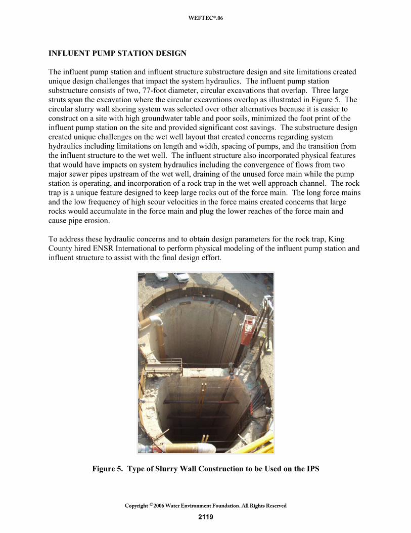
INFLUENT PUMP STATION DESIGN The influent pump station and influent structure substructure design and site limitations created unique design challenges that impact the system hydraulics. The influent pump station substructure consists of two, 77-foot diameter, circular excavations that overlap. Three large struts span the excavation where the circular excavations overlap as illustrated in Figure 5. The circular slurry wall shoring system was selected over other alternatives because it is easier to construct on a site with high groundwater table and poor soils, minimized the foot print of the influent pump station on the site and provided significant cost savings. The substructure design created unique challenges on the wet well layout that created concerns regarding system hydraulics including limitations on length and width, spacing of pumps, and the transition from the influent structure to the wet well. The influent structure also incorporated physical features that would have impacts on system hydraulics including the convergence of flows from two major sewer pipes upstream of the wet well, draining of the unused force main while the pump station is operating, and incorporation of a rock trap in the wet well approach channel. The rock trap is a unique feature designed to keep large rocks out of the force main. The long force mains and the low frequency of high scour velocities in the force mains created concerns that large rocks would accumulate in the force main and plug the lower reaches of the force main and cause pipe erosion. To address these hydraulic concerns and to obtain design parameters for the rock trap, King County hired ENSR International to perform physical modeling of the influent pump station and influent structure to assist with the final design effort.
Figure 5. Type of Slurry Wall Construction to be Used on the IPS
2119
WEFTEC®.06
Copyright 2006 Water Environment Foundation. All Rights Reserved©

MODELING ENSR International conducted a study of the influent structure, wet well, and rock catcher using a scale physical hydraulic model. The objective of the study was to: evaluate the performance of the wet well design, influent structure layout, and rock catcher over a range of flow conditions. Figure 6 illustrates the prototype model, which was constructed at a scale of 1:6. The model included the following elements
• Installation of 10 diameters of upstream sewer pipe for each influent sewer.
• Influent structure including fillets, rock catcher, force main drain lines, and rock catcher bypass line.
• Pump station wet well including ogee ramp and wet well contraction for smaller pumps.
• Suction piping for four 50-mgd pumps and two 25-mgd pumps, including long radius elbow, eccentric plug valve and long radius reducing elbow.
For the model, the sewer piping was constructed of polyvinyl chloride (PVC) piping. The influent structure was constructed from waterproofed wood on raised wooded deck set on concrete blocks and internal details of the influent structure were fabricated from sheet metal and plastic. The wet well was constructed from water proofed wood on a raised wooden deck. The walls were fabricated from clear acrylic plastic to facilitate viewing of the flow conditions in the wet well. The suction piping was constructed from both clear, vacuum-molded acrylic and straight acrylic tubing to permit viewing flow conditions with the suction piping. Water was circulated through the model via two head boxes, one representing the North Creek c onnector, and one representing the Swamp Creek connector. The flow was withdrawn from the wet well via model suction piping to the location of the prototype pump, at the downstream end of the long radius reducing elbow, which is the downstream model boundary. The test program for the model consisted of four phases.
• Baseline testing to determine whether adverse hydraulic phenomena were present at initial design and to correct these deficiencies before further testing.
• Design development tests were conducted to evaluate different set point water levels in the wet well for flow conditions modeled.
• Sedimentation testing was conducted to measure the flow field through the rock catcher and evaluate the sediment capturing efficiency of the rock catcher and make design modifications.
• Documentation testing was conducted to verify that the recommended modifications developed through design development testing and sedimentation testing would result in satisfactory pump hydraulics over the expected range of operating conditions.
2120
WEFTEC®.06
Copyright 2006 Water Environment Foundation. All Rights Reserved©

Figure 6. Physical Model Arrangement
Table 1 summaries the observations and measurement collected for each test.
Table 1. Test Measurements and Instrumentation
Observation/Measurements Instrument Employed Water level Precision point gauge referenced to model elevation
datum, with an accuracy of +/- 3 mm. Model pump flow rates Laboratory standard calibrated orifice flow meter to
measure the total flow rate in the influent sewers. Elbow meters calibrated in situ using the orifice flow meter as a standard to measure the individual pump flow rate.
Pre-Swirl Neutrally pitched four-bladed rotor on free-turnig bearings, approx. 4 pipe diameters downstream from the pump impeller.
Vortex formation Visual observation and injected dye Flow velocity at impeller Laboratory standard calibrate Nixon velocity probe. Point velocity in rock catcher SonTek acoustic Doppler velocimeter Sediment size U.S. standard sieves Sediment weight U.S. standard scale.
2121
WEFTEC®.06
Copyright 2006 Water Environment Foundation. All Rights Reserved©

INFLUENT STRUCTURE Description The influent structure (IS) acts as a sewer junction as shown in Figure 7. Each influent source pipe discharges to open channels within the IS, with approximately 10-30 percent of the flow entering from the west and 70-90 percent from the south. The two sources combine and are conveyed eastward in a 9-foot wide, open channel for 20 feet and then through a 9 foot diameter influent pipe which discharges to the IPS wet well. The confluence of the two influent sources is located at the IPS wet well’s projected centerline, 90 feet upstream of the wet well’s ogee weir, which is within the Hydraulic Institute’s standard of 5 to 10 times the influent pipe diameter. The open channels in the IS were initially designed with 12-inch chamfers where the channel walls meet the channel invert.
Figure 7. Influent Structure Lower Level Plan
The IS size and shape had undergone numerous iterations during design development. The structure needs to support tunnel mining activities, pipe routing between the tunnels, and pipe routing to and from the IPS; it needs to establish hydraulic conditions entering the wet well; and it needs to be large enough to mitigate influent surge. A round structure was selected over rectangular, since shoring and bracing costs are much lower for an 80-foot deep round excavation. The diameter of the structure was primarily determined by the area required to mitigate influent surge.
2122
WEFTEC®.06
Copyright 2006 Water Environment Foundation. All Rights Reserved©
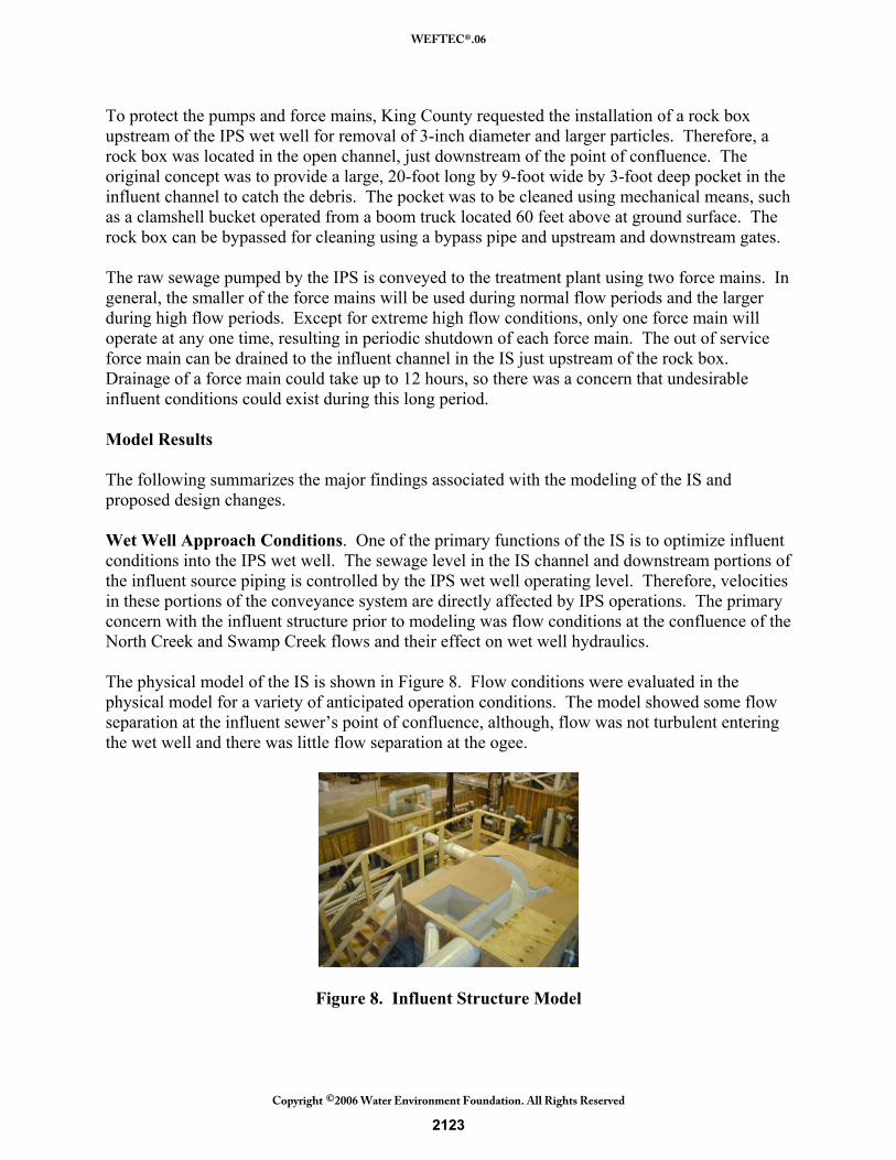
To protect the pumps and force mains, King County requested the installation of a rock box upstream of the IPS wet well for removal of 3-inch diameter and larger particles. Therefore, a rock box was located in the open channel, just downstream of the point of confluence. The original concept was to provide a large, 20-foot long by 9-foot wide by 3-foot deep pocket in the influent channel to catch the debris. The pocket was to be cleaned using mechanical means, such as a clamshell bucket operated from a boom truck located 60 feet above at ground surface. The rock box can be bypassed for cleaning using a bypass pipe and upstream and downstream gates. The raw sewage pumped by the IPS is conveyed to the treatment plant using two force mains. In general, the smaller of the force mains will be used during normal flow periods and the larger during high flow periods. Except for extreme high flow conditions, only one force main will operate at any one time, resulting in periodic shutdown of each force main. The out of service force main can be drained to the influent channel in the IS just upstream of the rock box. Drainage of a force main could take up to 12 hours, so there was a concern that undesirable influent conditions could exist during this long period. Model Results The following summarizes the major findings associated with the modeling of the IS and proposed design changes. Wet Well Approach Conditions. One of the primary functions of the IS is to optimize influent conditions into the IPS wet well. The sewage level in the IS channel and downstream portions of the influent source piping is controlled by the IPS wet well operating level. Therefore, velocities in these portions of the conveyance system are directly affected by IPS operations. The primary concern with the influent structure prior to modeling was flow conditions at the confluence of the North Creek and Swamp Creek flows and their effect on wet well hydraulics. The physical model of the IS is shown in Figure 8. Flow conditions were evaluated in the physical model for a variety of anticipated operation conditions. The model showed some flow separation at the influent sewer’s point of confluence, although, flow was not turbulent entering the wet well and there was little flow separation at the ogee.
Figure 8. Influent Structure Model
2123
WEFTEC®.06
Copyright 2006 Water Environment Foundation. All Rights Reserved©

Force Main and Effluent Draining. The IPS was designed to allow the force mains and effluent pipe to be drained into the IS channel when not in use for extending periods of time or for inspection. Flow conditions were evaluated in the physical model for normal IPS operations with the force main drain discharging into the influent channel. The model showed a slight increase in flow separation at the influent sewer’s point of confluence, however, flow was not turbulent entering the wet well and there was little flow separation at the ogee. Dye injections are shown in Figure 9 for when the force main drain was closed and in Figure 10 when open.
Figure 9. Force Main Drain Closed
Figure 10. Force Main Drain Open
Rock Box Design. King County incorporated the rock box into the IPS design to minimize build up of rocks in the lower portion of the force mains and to minimize erosion problems in the force main. King County’s recent experience at other pump stations included accumulation of the large quantities of rocks in the lower portion of force mains when pumps were not operated regularly at peak capacities. Recently, two of the County’s force mains failed due to erosion associated with large rocks rolling along the force main invert for years. The pumps did not operate at sufficient scouring velocity to blow the rocks out the discharge. A series of tests were performed to evaluate the hydraulics of the rock box. Three dimensional velocity maps were created for the original 20-foot long by 9-foot wide by 3-foot deep rock box at three flow conditions: 25 mgd, 45 mgd, and 95 mgd. The velocity distributions show similar trends for each flow condition, with the overall velocity magnitudes increasing with flow rate. The velocity maps at 45 mgd are presented in Figures 11 and 12. The flow tended to roll along
2124
WEFTEC®.06
Copyright 2006 Water Environment Foundation. All Rights Reserved©
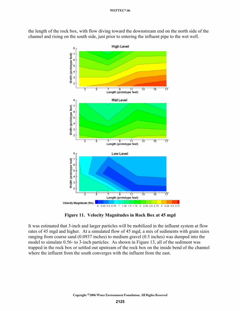
the length of the rock box, with flow diving toward the downstream end on the north side of the channel and rising on the south side, just prior to entering the influent pipe to the wet well.
Figure 11. Velocity Magnitudes in Rock Box at 45 mgd It was estimated that 3-inch and larger particles will be mobilized in the influent system at flow rates of 45 mgd and higher. At a simulated flow of 45 mgd, a mix of sediments with grain sizes ranging from course sand (0.0937 inches) to medium gravel (0.5 inches) was dumped into the model to simulate 0.56- to 3-inch particles. As shown in Figure 13, all of the sediment was trapped in the rock box or settled out upstream of the rock box on the inside bend of the channel where the influent from the south converges with the influent from the east.
2125
WEFTEC®.06
Copyright 2006 Water Environment Foundation. All Rights Reserved©

Figure 12. Vertical Velocity Magnitudes in Rock Box at 45 mgd The influent channel and rock box were modified to prevent depositions in the channel upstream of the box and to reduce capture of particles less than 3 inches. The fillet in the rock box section of the channel was increased from 12 inches to 31.5 inches, which reduced sediment deposition in the channel. The larger chamfer also provides a better transition to the 9 foot diameter influent pipe to the wet well. The rock box was significantly reduces in size to a slot. The slot works on the principal that larger sediment particles have a higher settling velocity than smaller particles. As particle pass over the slot, smaller ones can be carried past with the flow, but larger particles fall out of the flow into the slot. The slot size and location were varied through several iterations to find an optimal arrangement. An arrangement that did not capture some of the smaller sediment was not found due to the stochastic nature of the sediment motion in turbulent flow.
2126
WEFTEC®.06
Copyright 2006 Water Environment Foundation. All Rights Reserved©

Figure 13. Gravel in Initial Rock Box and Inside Bend The rock box arrangement that worked best was an 18-inch wide slot that spanned the width of the influent channel with an adverse slope on the downstream side of the slot. Small rocks are able to pass over the slot or be carried along on the side of the fillet to the IPS wet well, while larger sediment directly falls or rolls back into the slot. As shown in Figure 14, when the sediment mixture was added upstream of the revised rock box at a simulated flow rate of 45 mgd, 100 percent of the 3-inch diameter particles and 60 percent of the fine grained particles were captured in the rock box. The larger chamfer eliminated depositions in the channel.
Figure 14. Revised Rock Box and Fillet
2127
WEFTEC®.06
Copyright 2006 Water Environment Foundation. All Rights Reserved©

INFLUENT PUMP STATION WET WELL Description The wet well design was developed based on Hydraulic Institute standards and Pumping Station Design. Because the pumping system uses two pump sizes, one for low range and one for high range flows, the wet well has two sections with widths of 108 inches and 78 inches, based on the inlet bell diameter of each pump size (42-inch and 30-inch, respectively). The double barrel shape of the IPS combined with the center struts resulted in wet well dimensions that were constrained in length and width relative to the space available to install the associated array of pumps on the other side of the wet well wall. The east end of the wet well is limited by the wet well access stairwell, and the west end is limited by the wall which has a southwest/northeast orientation. The pump station has six pumps and the spacing between pumps varies because of structural constraints associated with horizontal struts and the pump spacing is not typical of Hydraulic Institute standards. Because the inlet end of the wet well is close to the substructure wall, the ogee ramp, used to induce self-cleaning flows, was steepened (30 degrees from vertical) so that the crest of the ogee remained inside the circular substructure. Due to width limitations within the wet well caused by a circular substructure, wet well fillets, were not included in the design typical of trench style wet wells. However, the crest was still required to encroach slightly into the wall. The following results from the model were used to modify the design. Model Results Operating Depth. With the wide variability in influent flows, a continuously variable operating depth based on flow would be needed to maintain minimum velocities in the approach channel. The automation for this type of level control was not desired and the identification of a single-level set point control was attempted. A level of 65.2 feet (2-ft approach depth) was established. At this level, the velocities in the inlet channels remain above 1.5 foot per second for less-than-average flows and the periods of minimum flow at which sedimentation could occur are brief. The model results showed that a hydraulic jump occurred within the wet well as flow nears 90 mgd, entraining significant volumes of air. A second control level was therefore necessary and was set at 68 feet (4.8-ft approach depth). The transition between control depths occurs at 60 mgd, as measured on the force main flow meter and controlled by the system program. Inlet Conditions. The inlet conditions were defined by the combination of curved walls in the wet well, circular inlet pipe, and the ogee ramp length as shown in Figure 15. This combination resulted in an abrupt transition from the circular pipe to the square channel section at the crest of the ogee.
2128
WEFTEC®.06
Copyright 2006 Water Environment Foundation. All Rights Reserved©
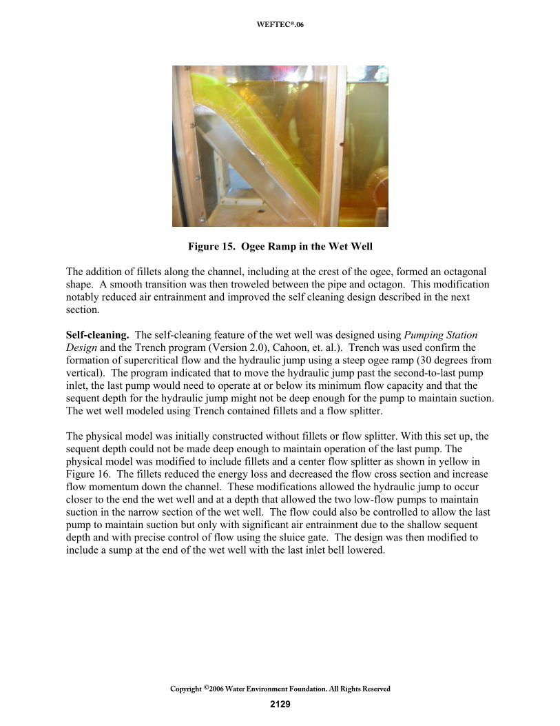
Figure 15. Ogee Ramp in the Wet Well The addition of fillets along the channel, including at the crest of the ogee, formed an octagonal shape. A smooth transition was then troweled between the pipe and octagon. This modification notably reduced air entrainment and improved the self cleaning design described in the next section. Self-cleaning. The self-cleaning feature of the wet well was designed using Pumping Station Design and the Trench program (Version 2.0), Cahoon, et. al.). Trench was used confirm the formation of supercritical flow and the hydraulic jump using a steep ogee ramp (30 degrees from vertical). The program indicated that to move the hydraulic jump past the second-to-last pump inlet, the last pump would need to operate at or below its minimum flow capacity and that the sequent depth for the hydraulic jump might not be deep enough for the pump to maintain suction. The wet well modeled using Trench contained fillets and a flow splitter. The physical model was initially constructed without fillets or flow splitter. With this set up, the sequent depth could not be made deep enough to maintain operation of the last pump. The physical model was modified to include fillets and a center flow splitter as shown in yellow in Figure 16. The fillets reduced the energy loss and decreased the flow cross section and increase flow momentum down the channel. These modifications allowed the hydraulic jump to occur closer to the end the wet well and at a depth that allowed the two low-flow pumps to maintain suction in the narrow section of the wet well. The flow could also be controlled to allow the last pump to maintain suction but only with significant air entrainment due to the shallow sequent depth and with precise control of flow using the sluice gate. The design was then modified to include a sump at the end of the wet well with the last inlet bell lowered.
2129
WEFTEC®.06
Copyright 2006 Water Environment Foundation. All Rights Reserved©

Figure 15. Final Model Wet Well Design with Fillets CONCLUSIONS The structural physical constraints associated with the circular substructure combined with six pumps resulted in a wet well that did not conform to ANSI/HI 9.8 standards. The physical model results were used to modify the design to optimize hydraulic conditions in the wet well, including the wet well control strategies. No design guidelines exist for a rock box, but removing the rocks before they enter the wet well and force main was critical to the design criteria. The physical model provided the optimal design parameters for the rock box. The follow changes were made to the design: Rock Box. With the significant reduction in rock box size, it became possible to design the rock box as a removable basket that fits into the channel invert as shown in Figure 17. Using a basket simplifies cleaning operations since the basket can be removed for dumping as it nears capacity using a boom truck from 60 feet above. The rock box is nested inside another box, which is used to catch debris during removal of the primary box.
Figure 17. Rock Box Design
2130
WEFTEC®.06
Copyright 2006 Water Environment Foundation. All Rights Reserved©

Force Main and Effluent Draining. The force mains and effluent pipeline drain into a common pipe that discharges to the influent channel in the IS. Modeling showed that the proposed drain system had minimal effect on flow patterns into the IPS wet well. The system’s success is due in part to an oversized discharge pipe, which keeps the discharge velocity head low. In addition, most of the head in the force mains and effluent pipe would be burned off using control valves. Fillets. Fillets were added to the inlet channel within the IS and along the ogee ramp and the entire length of the wet well. A flow splitter beginning at the toe of the ogee ramp to the downstream inlet sump. The fillets helped keep velocities at minimum scouring velocities within the influent channel and significantly improved the wet well cleaning cycle. Operating Levels. Control strategies were modified to accommodate two operating levels within the IS depending on flow rates. REFERENCES Sanks, et. al., Pumping Station Design (2nd Edition), Butterworths Heimemann, 1998 Physical Hydraulic Model Study of the Brightwater Treatment Facility Influent Pump Station Final Report. October 2005. ENSR International. Trench 2.0 program developed by Dr. Joel Cahoon, Montana State University
2131
WEFTEC®.06
Copyright 2006 Water Environment Foundation. All Rights Reserved©