Hydraulic and Pneumatic Fracturing - CLU-IN
26
Hydraulic and Pneumatic Fracturing OST Reference # 1917 (Hydraulic Fracturing) OST Reference # 1916 (Pneumatic Fracturing) Subsurface Contaminants Focus Area Prepared for U.S. Department of Energy Office of Environmental Management Office of Science and Technology February 1998 Demonstrated at U.S. Department of Energy Portsmouth Gaseous Diffusion Plant, Ohio and Department of Defense and Commercial Sites
Transcript of Hydraulic and Pneumatic Fracturing - CLU-IN

Hydraulic and Pneumatic Fracturing
OST Reference # 1917 (Hydraulic Fracturing)
OST Reference # 1916 (Pneumatic Fracturing)
Subsurface Contaminants Focus Area
Prepared forU.S. Department of Energy
Office of Environmental ManagementOffice of Science and Technology
February 1998
Demonstrated atU.S. Department of Energy
Portsmouth Gaseous Diffusion Plant, Ohio andDepartment of Defense and Commercial Sites

CONTENTS
DISCLAIMER
PURPOSE OF THIS DOCUMENT
1. SUMMARY
2. TECHNOLOGY DESCRIPTION
3. PERFORMANCE
4. TECHNOLOGY APPLICABILITY AND ALTERNATIVES
5. COST
6. REGULATORY AND POLICY ISSUES
7. LESSONS LEARNED
APPENDICES
A. REFERENCES
B. COMPARING OF HYDRAULIC AND PNEUMATIC FRACTURING

DISCLAIMER
This report was prepared as an account of work sponsored by an agency of the United States Government.Neither the United States Government nor any agency thereof, nor any of their employees, makes anywarranty, express or implied, or assumes any legal liability or responsibility for the accuracy,completeness, or usefulness of any information, apparatus, product, or process disclosed, or represents thatits use would not infringe privately owned rights. Reference herein to any specific commercial product,process, or service by trade name, trademark, manufacturer, or otherwise does not necessarily constitute orimply its endorsement, recommendation, or favoring by the United States Government or any agencythereof. The views and opinions of authors expressed herein do not necessarily state or reflect those of theUnited States Government or any agency thereof.

PURPOSE OF THIS DOCUMENT
Innovative Technology Summary Reports are designed to provide potential users with the information theyneed to quickly determine if a technology would apply to a particular environmental management problem.They are also designed for readers who may recommend that a technology be considered by prospectiveusers.
Each report describes a technology, system, or process that has been developed and tested with fundingfrom DOE's Office of Science and Technology (OST). A report presents the full range of problems that atechnology, system, or process will address and its advantages to the DOE cleanup in terms of systemperformance, cost, and cleanup effectiveness. Most reports include comparisons to baseline technologies aswell as other competing technologies. Information about commercial availability and technology readinessfor implementation is also included. Innovative Technology Summary Reports are intended to providesummary information. References for more detailed information are provided in an appendix.
Efforts have been made to provide key data describing the performance, cost, and regulatory acceptance ofthe technology. If this information was not available at the time of publication, the omission is noted.
All published Innovative Technology Summary Reports are available online at http://em-50.em.doe.gov.

SECTION I
SUMMARYTechnology Summary
Hydraulic and pneumatic fracturing are two technologies that induce fractures in the subsurface to enhancethe remediation of contaminants both above and below the water table. These technologies are particularlyuseful and cost-effective at contaminated sites with low-permeability soil and geologic media, such asclays, shales, and tight sandstones where remediation, without some sort of permeability enhancement, isdifficult or impossible. However, the usefulness of fracturing technology is not limited to low-permeabilitysites.
Enhanced access is provided by creating new or enlarging existing fractures in the subsurface, whichimproves fluid flow to encourage removal or treatment of contaminants (see Figure 1). The innovationadapts a petroleum recovery technique, used for a number of years, to the environmental field. Fracturingcan then be combined with other technologies to provide an effective remediation system at difficult sites.
Figure 1. Fracturing of low-permeability formation. Extraction or treatment can be accomplishedeither in the fluid injection borehole or in adjacent boreholes.
BenefitsFractures can enhance the performance of remediation technologies in low-permeability strata by
? increasing the permeability of the soil,

? increasing the effective radius of recovery or injection wells,
? increasing potential contact area with contaminated soils, and
? intersecting natural fractures, where contaminants may have localized.
Induced fractures promote better extraction of contaminants from or delivery of materials (gases,liquids, or solids) to the subsurface, producing a more effective in situ remediation. Examples ofinnovative materials that can be introduced through fractures include
? nutrients or slowly dissolving oxygen sources to improve bioremediation processes,
? electrically conductive compounds (e.g., graphite) to improve electrokinetic processes, and
? reactant materials such as zero-valent iron or permanganate.
? Creation of fractures does not add significant up-front costs (up to a few percent) to an overallremediation system, and it may provide significant reduction in the life-cycle costs to remediate asite because fewer wells may be required and cleanup may be accomplished more rapidly.
How it works? Fractures are typically created in a horizontal or subhorizontal plane at specific horizons (<2 ft) by
injecting a fluid (either liquid or gaseous) into a sealed borehole until the pressure exceeds acritical value, thus nucleating a fracture. After injection is complete, fractures are held opennaturally or with an introduced proppant, a material injected to prop open the fractures. If a liquid(e.g., guar gum gel) is used to create the fracture, a granular proppant can be introduced to assistwith maintenance of fracture openings.
? The direction of fracture propagation is controlled by the state of stress in the subsurface. Siteswith horizontal stress greater than vertical stress will produce horizontal or subhorizontalfractures. These sites typically consist of overconsolidated fine-grained deposits (silts and clays).For pneumatic fracturing, a directional nozzle can be used to control the direction of fracturepropagation.
Demonstration SummaryThis report covers demonstrations that took place between July 1991 and August 1996.
? Hydraulic fracturing has been extensively researched and used in the petroleum industry for over50 years. It has required modification for use in the environmental field. Since the early 1990s,research has been conducted on the viability of both pneumatic and hydraulic fracturing forenvironmental applications.
? A number of demonstrations of hydraulic and pneumatic fracturing have been conducted to showtheir applicability to the environmental field. Both technologies were demonstrated under the U.S.Environmental Protection Agency's (EPA) Superfund Innovative Technology Evaluation (SITE)program in the early 1990s. Technology Evaluation and Applications Analysis Reports areavailable for both technologies (see references).

? These technologies have been demonstrated and deployed at U.S. Departments of Energy andDefense sites and commercial sites. Funding to support some of the technology demonstrationshas been provided by the U.S. Department of Energy's (DOE) Office of Science and Technologyunder the Subsurface Contaminants Focus Area Program.
? In cooperation with the University of Cincinnati, FRX, Inc. has modified and developed hydraulicfracturing for environmental applications. Accutech Remedial Systems, Inc. (ARS) in cooperationwith the New Jersey Institute of Technology (NJIT) has developed pneumatic fracturing forenvironmental applications.
? Bench-scale tests, followed by pilot- and field-scale tests on both clean and contaminated sites,have been conducted by NJIT and ARS, using pneumatic fracturing. Terra Vac, Malcolm Pirnie,and others have also participated in pneumatic fracturing projects. DOE has supported severaldemonstrations of pneumatic fracturing, including one at Tinker Air Force Base and one at DOE'sPortsmouth Gaseous Diffusion Plant. NJIT patented pneumatic fracturing for environmentalapplications. In 1992, the institute licensed the technology to ARS.
? In cooperation with the University of Cincinnati, FRX has conducted pilot- and field-scale tests ofhydraulic fracturing on both clean and contaminated sites in nine states (Texas, Ohio, Idaho,Illinois, Connecticut, Maine, Michigan, New Jersey, and Colorado) and Canada. GolderAssociates Ltd. has conducted bench-, pilot-, and field-scale tests concentrating on hydraulicfracturing. A hydraulic fracturing demonstration has been completed at DOE's PortsmouthGaseous Diffusion Plant. Future development will include coupling of in situ mass transfer anddestruction processes. Advanced applications such as injection of graphite, iron filings, oxidants,and activated carbon were tested.
Key Results? Hydraulic and pneumatic fracturing at geologically appropriate sites have significantly improved
recovery of contaminated fluids (~10 to >1,000 times). These technologies typically havegenerated fractures that significantly increase (ten fold) the radius of influence for verticalrecovery wells at the sites.
? Hydraulically developed fractures were demonstrated to be effective for a period of more than oneyear. Vapor flow rates were increased by 15 to 30 times that of unfractured wells. Water flow rateswere increased by 25 to 40 times that of unfractured wells.
? Hydraulic and pneumatic fracturing have been used in conjunction with soil vapor extraction,pump and treat, bioremediation, free product recovery, and in situ vitrification at contaminatedsites. Demonstrations of other applications, such as passive chemical barriers or electrokinetics,are under way.
Commercial Availability
Hydraulic fracturing is commercially available from several companies: FRX, Inc., Golder Associates Ltd.,Hayward Baker Environmental, Inc., and perhaps others. Larger scale, more costly applications areperformed by several companies for oilfield applications. Pneumatic fracturing is commercially availablefrom ARS. ARS has used pneumatic fracturing at over 30 sites in North America. ARS has recently signedan agreement with DOWA Mining Company LTD of Japan to market pneumatic fracturing in Japan.

ContactsTechnical
Pneumatic
John Liskowitz/Ted Keffer, Accutech Remedial Systems, Inc., Keyport, New Jersey (732) 739-6444John Schuring, New Jersey Institute of Technology, Newark, New Jersey (973) 596-5849
Hydraulic
Larry Murdoch, Clemson University, Clemson, South Carolina (864) 656-2597William Slack, FRX, Inc., Cincinnati, Ohio (513) 556-2526Robert Siegrist, Oak Ridge National Laboratory, Colorado School of Mines, Golden, Colorado (303) 273-3490
Management
Skip Chamberlain, Subsurface Contaminants Focus Area HQ Lead, DOE EM50, Germantown, Maryland(301) 903-7248James Wright, Subsurface Contaminants Focus Area Program Manager, DOE Savannah River, Aiken,South Carolina (803) 725-5608
(Information in this report is based on technologies as implemented by ARS and FRX.)
Other
All published Innovative Technology Summary Reports are available online at http://em-50.em.doe.gov.The Technology Management System, also available through the EM50 web site, provides informationabout OST programs, technologies, and problems. The OST Reference Numbers for hydraulic andpneumatic fracturing are 1917 and 1916, respectively.

SECTION 2TECHNOLOGY DESCRIPTION
Overall Process DefinitionHydraulic Fracturing
A schematic diagram of the hydraulic fracturing process is shown in Figure 2.
Figure 2. Hydraulic fracturing typically uses water to induce fractures.Source:U.S. EPA, 1994.
Hydraulic Fracturing Equipment
The fracturing equipment consists of a rod, a tool to create an initial notch, a continuous slurry mixer, apositive displacement pump mounted on a trailer, and the fracture mixture (fluid and proppant).
Hydraulic Fracturing Process
? A well is drilled and cased down to the depth where fractures are desired in lithified sediments. Inunlithified sediments, a straddle-packer system is used. The lance, a rod with a cone-shaped end, isintroduced into the bottom of the borehole and is driven to the depth at which the fracture is desired.The lance tip remains in the soil, whereas the lance is later removed from the borehole.
? A water jet (steel tubing with a narrow orifice at one end) is inserted into the cone-shaped rod, andwater is pumped through the tubing to create a high-pressure(3,500 psi) water jet. The jet is rotatedwithin the borehole to create a disc-shaped horizontal notch extending 4 to 6 in from the borehole.
? The gel-laden proppant is then pumped into the notch under relatively low pressures (60 psig) to createa fracture. Lateral pressure from the soil on the outer wall of the casing effectively seals the casing andprevents leakage of the slurry. The fracture begins at the notch and grows radially up to about 20 ftfrom the borehole wall. The gel to sand ratio is adjusted from fracture to fracture, depending on depthand site-specific soil conditions.
Pneumatic Fracturing
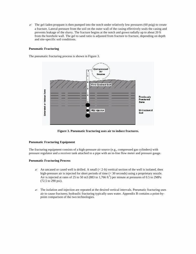
The pneumatic fracturing process is shown in Figure 3.
Figure 3. Pneumatic fracturing uses air to induce fractures.
Pneumatic Fracturing Equipment
The fracturing equipment consists of a high-pressure air source (e.g., compressed gas cylinders) withpressure regulator and a receiver tank attached to a pipe with an in-line flow meter and pressure gauge.
Pneumatic Fracturing Process
? An uncased or cased well is drilled. A small (< 2-ft) vertical section of the well is isolated, thenhigh-pressure air is injected for short periods of time (< 30 seconds) using a proprietary nozzle.Air is injected at rates of 25 to 50 m3 (883 to 1,766 ft3) per minute at pressures of 0.5 to 2MPa(72.5 to 290 psi).
? The isolation and injection are repeated at the desired vertical intervals. Pneumatic fracturing usesair to cause fractures; hydraulic fracturing typically uses water. Appendix B contains a point-by-point comparison of the two technologies.

System Operation? The direction of fracture propagation will be perpendicular to the minimum principal stress in the
subsurface at a particular site. Recent field data indicate that soil fabric or lithology may have agreater influence on fracture orientation than the in situ state of stress in the soil mass in some soildeposits.
? Injection pressure required to initiate a fracture generally increases with increasing depth, injectionrate, and fluid viscosity.
Injection fluids
? Guar gum gel is commonly used in hydraulic fracturing. The gel carries sand into the subsurfaceto prop the fractures open.
? Guar gum is a food additive and when mixed with water forms a short-chain polymer with theconsistency of molasses.
? A crosslinker is added to lengthen the polymer chains and create a thick gel capable of suspendinghigh concentrations of sand.
? An enzyme is added to the gel that breaks down the polymer chains in a few hours to allowrecovery of the thinned liquid.
? Pneumatic fracturing (i.e., injection of air) typically uses no propping agents and is thus bestapplied at sites where the geology is conducive to maintaining open any dilated existing fracturesor newly created fractures.
Leakoff
? Leakoff occurs when some of the injected fluid flows out through the walls of the fracture. Therate of fracture propagation decreases as the rate of leakoff increases, and propagation ceasesentirely when the leakoff rate equals the rate of injection.
? Leakoff generally controls the size of the fractures. Leakoff is minimized by controlling amountand rate of injection.
Monitoring Fracture Location
? The most widely used method of monitoring fracture location is measuring the displacement of theground surface (Figure 4). Field staffs can survey before or after fracturing, or tiltmeters can beused during fracture propagation. Pressure influence in surrounding monitoring wells can also bemeasured to determine fracture locations.

Figure 4. Plan and section of a typical hydraulic fracture created in overconsolidated silty clay.Source: U.S. EPA 1994.</CAPTION< Center>

SECTION 3PERFORMANCE
Specific examples of demonstrations for each of the technologies, with focus on those supported by DOE,are presented in this section.
Demonstration PlanMajor elements of the demonstrations included the following:
? Establish initial flow rates and contaminant extraction levels from extraction and monitoringwells. Sample monitoring wells to determine whether fractures connect fracture wells tomonitoring wells.
? Establish final flow rates and contaminant extraction levels from extraction and monitoring wells.
? Determine pressures at both monitoring wells and extraction wells.
Demonstration SummaryHydraulic Fracturing
? Hydraulic fracturing was demonstrated under EPA's Superfund Innovative Technology Evaluation(SITE) program in July 1991 at sites in Oak Brook, Illinois and Dayton, Ohio. Both sitescontained low-permeability soils (<10_7 cm/sec) that were contaminated with volatile organiccompounds (VOCs). Fracturing was accomplished to a depth of 15 ft below ground surface.
o In Illinois, contaminants removed by soil vapor extraction were increased by 7 to 14times; the area of influence was 30 times greater after fracturing.
o In Ohio, flow of water into the fractured well was increased 25 to 40 times; thebioremediation rate was increased by approximately 75 percent.
? Demonstrations have also been conducted at DOE's Portsmouth Gaseous Diffusion Plant in Ohio(August 1996); the Laidlaw site near Sarnia, Ontario, Canada (cofunded by DOE); a Bristol,Tennessee site; a Beaumont, Texas site; and the Linemaster Switch Superfund Site in Woodstock,Connecticut. At the Portsmouth Gaseous Diffusion Plant, fractures were propped with sand,oxidants, and reductants; the site was then treated with hot air/steam enhanced air flushing and insitu chemical degradation.
Pneumatic Fracturing
? An EPA SITE demonstration was conducted at a site in Hillsborough, New Jersey in 1992.Fractures created during the demonstration significantly increased the effective radius of influenceand increased the rate of mass removal about 675 percent over the rates measured beforefracturing. By installing wells to be used as passive inlets/outlets, improvements in mass removalrates were as high as 2,300 percent.

? DOE supported demonstrations at the Tinker Air Force Base in Oklahoma and the PortsmouthGaseous Diffusion Plant in Ohio.
Treatment PerformanceHydraulic Fracturing
Laidlaw Site, Sarnia, OntarioThe sheet-pile test cell was a clean site located adjacent to a major hazardous waste landfill. A syntheticgasoline blend with a tracer of trichloroethylene was released into the cell in 1992. Soil vapor extractionwas then initiated. Surface materials at this location are composed of clay-rich glacial till. In August 1994,hydraulic fracturing was conducted. Fifteen fractures were emplaced at nine locations outside of the sheet-pile cell at depths of 1.2 and 5.6 m.
Key Results
? Minimum surface uplift from the fracturing was observed at 1 to 4.65 cm.
? More symmetric fractures were created at shallow depths, while asymmetric fractures werecreated at depths greater than 2.5 m. For fractures at depths greater than 2.5 m, the dip of thefractures increased with the depth of the fracture.
Key Results from Other Sites
Recovery performance of wells that have been hydraulically fractured generally increases by a factor of 1.5to 10, but the range varies up to 100 or more. Several examples of demonstration performance are listed inTable 1.
Table 1. Data from a variety of sites demonstrate hydraulic fracturing's ability to improveremediation
Site Name Contaminant/GeologyMass RecoveryFactor Increase
Radius of InfluenceImprovement
Oak Brook, IL *VOCs in silty clay 7 to 14 30 timesDayton, OH *VOCs in silty clay 25 to 40 not reported (NR)Bristol, TN **DNAPLs/fractured bedrock 2.8 to 6.2 30 times
Regina,Saskatchewan *VOCs in silty clay NR 25 timesCalgary, Alberta *VOCs in silty clay 10 NRLinemaster, CT Solvents in till 4 to 6 NR
Beaumont, TX **DNAPLs in silty clay 50 ~25 times* volatile organic compounds** dense nonaqueous phase liquids
Pneumatic FracturingTinker Air Force Base, OklahomaFuel oil had leaked from an underground storage tank into interbedded sedimentary strata. A pump-and-treat system was installed and recovered 155 gal per month for 17 months. Four wells were installed at thesite and pneumatically fractured.
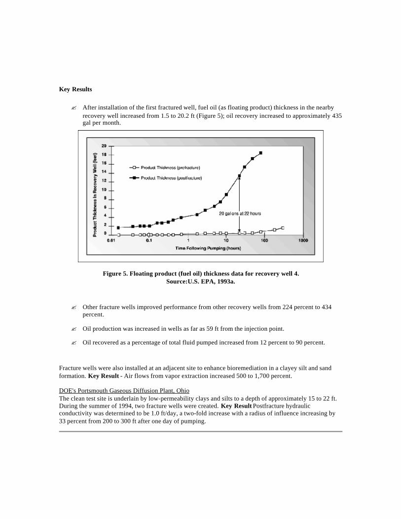
Key Results
? After installation of the first fractured well, fuel oil (as floating product) thickness in the nearbyrecovery well increased from 1.5 to 20.2 ft (Figure 5); oil recovery increased to approximately 435gal per month.
Figure 5. Floating product (fuel oil) thickness data for recovery well 4.Source:U.S. EPA, 1993a.
? Other fracture wells improved performance from other recovery wells from 224 percent to 434percent.
? Oil production was increased in wells as far as 59 ft from the injection point.
? Oil recovered as a percentage of total fluid pumped increased from 12 percent to 90 percent.
Fracture wells were also installed at an adjacent site to enhance bioremediation in a clayey silt and sandformation. Key Result - Air flows from vapor extraction increased 500 to 1,700 percent.
DOE's Portsmouth Gaseous Diffusion Plant, OhioThe clean test site is underlain by low-permeability clays and silts to a depth of approximately 15 to 22 ft.During the summer of 1994, two fracture wells were created. Key Result Postfracture hydraulicconductivity was determined to be 1.0 ft/day, a two-fold increase with a radius of influence increasing by33 percent from 200 to 300 ft after one day of pumping.

SECTION 4TECHNOLOGY APPLICABILITY AND
ALTERNATIVES
Competing TechnologiesThe baseline against which fracturing can be compared is remediation, such as soil vapor extraction,without fracturing. Improvements in recovery of contaminants after fracturing can then be used to compareto the baseline.
Hydraulic and pneumatic fracturing are competing technologies. A site being considered for fracturingmust be evaluated to determine which technology would perform as required and be the most cost effective.A comparison of the two technologies is presented in Appendix B (from Keffer et al. 1996).
Another technology designed to enhance access to the subsurface is that of directionally drilled horizontalwells. Fracturing of geologic media and soils at low-permeability sites contaminated with volatile organiccompounds (VOCs) also competes with soil heating technologies, designed to enhance contaminantremoval by soil vapor extraction (see Six-Phase Soil Heating, an Innovative Technology Summary Report[ITSR], DOE 1995, as an example.) In situ enhanced soil mixing has been used to treat VOC-conaminatedsites with low-permeability soils and geologic media (see In Situ Enhanced Soil Mixing, ITSR, DOE1996). Other remediation technologies such as surfactant flushing and bioremediation do not competedirectly as they do not enhance access to the subsurface. Fracturing technologies could be used as anenhancement to these technologies.
Technology Applicability? Fracturing enhances current remediation technologies by increasing permeabilities and improving
flow, recovery, and destruction rates for
o vapor extraction,
o ground-water extraction,
o bioremediation,
o free product recovery for light nonaqueous phase liquids (LNAPLs) and densenonaqueous phase liquids (DNAPLs),
o possibly electrokinetics and other innovative in situ technologies, such as permeablebarriers with chemical oxidants or reductants.
? Hydraulic and pneumatic fracturing for fluid recovery enhancement have been successfullydemonstrated on the field scale in both the vadose and saturated zones.
? Hydraulic and pneumatic fracturing are well suited for sites with an assortment of underlyingstrata, especially for low-permeability sandstones, clays, siltstones, and shales.

Implementation Considerations
Table 2 summarizes the factors that should be considered when deciding whether a site is appropriate forfracturing and, if so, how best to design the project (modified from EPA 1994).
Table 2. Design factors for selection of fracturing technology at a site
Factor Favorable Unfavorable
Formationpermeability Moderate to low (k < 10-6 cm2) Unnecessary in high permeability formations
Formation type Rock or fine-grained sediment Course-grained sediment
Formation structure Horizontal bedding planes Vertical structuresSand proppant Unlithified, saturated sediments May be unnecessary in consolidated units
State of stressHorizontal stress > vertical stress(overconsolidated)
Horizontal stress < vertical stress (normallyconsolidated)
Site conditionsOpen ground over fracture; no buriedutilities
Structures sensitive to displacement overfracture; buried utilities
Depth 1 to 8 m Surface or >8 m
Patents/Commercialization/SponsorHydraulic Fracturing
? Hydraulic fracturing has been used extensively for over 50 years in the petroleum industry.
? FRX, Inc. in cooperation with the University of Cincinnati modified and developed hydraulicfracturing for environmental applications.
? It has been demonstrated at a number of sites in North America for fluid recovery enhancementbut has not yet been fully implemented for a site cleanup.
? Hydraulic fracturing is commercially available from several companies: FRX, Inc. in Cincinnati,Ohio, Golder Associates Ltd. (20 offices in Canada), Hayward Baker Environmental, Inc. (11offices in the United States and an office in Vancouver, British Columbia, Canada), and perhapsothers.
Pneumatic Fracturing
? Pneumatic fracturing has been demonstrated at over 30 sites in North America and has beenutilized for full implementation of site cleanup at six or more sites.
? New Jersey Institute of Technology (NJIT) in Newark patented pneumatic fracturing forenvironmental applications.
? In 1992, NJIT licensed the technology to Accutech Remedial Systems in Keyport, New Jersey.

SECTION 5COST
MethodologyHydraulic Fracturing
EPA has reported the cost per single fracture ranging from $950 to $1,425. However, the cost is highlydependent upon the number of fractures to be placed in each borehole. EPA also reported a daily cost of$5,700 to create 4 to 6 fractures. Golder Associates Ltd. reports costs of $400 to $500 per fracture or$2,000 to $6,000 per well.
Pneumatic Fracturing
Pneumatic fracturing costs can be estimated to be similar to those of hydraulic fracturing. However, analternative cost estimating method, based upon dollars per pound of contaminant removed, was completedby EPA.
Cost Analysis
Hydraulic Fracturing
Cost data for hydraulic fracturing is presented in Table 3.
Table 3. Cost summary for hydraulic fracturing
Type of Cost Daily Cost ($)
Site preparation 1,000Permitting and regulatory 5,000Capital equipment rental 1,000
Startup 0Labor 2,000Supply and consumables 1,000
Utilities 0Effluent treatment and disposal 0Residual and waste shipping and handling 0
Analytical and monitoring 700Maintenance and modifications 0Demobilization 400
Total one-time costs 5,400Total daily costs 5,700
Estimated cost per fracture 950 to 1,425
Source: U.S. EPA 1993a.

Pneumatic Fracturing
Using the alternative cost estimating method devised by EPA for pneumatic fracturing, costs for the EPASITE demonstration in New Jersey were estimated at $140/lb of trichloroethylene removed for ahypothetical remediation. The following assumptions were applicable:
? Site, 100 ft by 150 ft
? Effective radius of influence, 25 ft
? 15 wells required for a 15 percent to 20 percent overlap
? One-year operating cycle with capital cost amortization
Costs for pneumatic fracturing were extrapolated from a 4-hour postfracture test:
? Labor, 29 percent
? Capital equipment, 22 percent
? Off-gas treatment, 19 percent
? Site preparation, 11 percent
? Residuals disposal, 10 percent
Other estimates predict pneumatic fracturing to cost $8 to $17 per cubic yard of soil treated. Fracturing canbe completed using a weekly rate of $15,000 to $20,000.
Cost ConclusionsFracturing technology can be compared to a baseline where no fracturing is done. The costs identifiedabove can then be considered in terms of the improvement in remediation performance (~ 150 percent to2,300 percent, Section 3). Large increases in contaminant mass removal efficiency produce more rapidcleanup, thus significantly reducing maintenance and operating costs over the life cycle of the project.

SECTION 6REGULATORY AND POLICY ISSUES
Regulatory ConsiderationsTo date, no special permits are required for the use of pneumatic or hydraulic fracturing. Permittingexpenses would typically be covered under existing requirements for the remedial action at the site.Fracturing activities are considered under the requirements for the remediation of a particular site.
? Gels used in hydraulic fracturing (usually guar gum) are biodegradable and nontoxic. Otheradditives, such as the proppants (usually sand of various grain sizes) and water, are naturallyoccurring and not a regulatory concern.
? However, some state agencies are concerned about injection of fluids and materials that may alterthe pH of the subsurface.
? Another area of concern stems from lack of control over fracture generation.
o Field staff may be uncertain about the effect of fracturing on a strata, such as the quantity, size and direction of the generated fractures. Information on site geology/hydrologycan be used to model the placement of fractures.
o In a highly fractured system, further fracturing may drive contamination away from thepressure front, thus increasing the area of contamination.
Safety, Risks, Benefits, and Community ReactionWorker Safety
? Health and safety issues for fracturing technologies do not present significant hazards overconventional field remediation operations.
? Pressures used are high enough to require extreme caution. All equipment is checked regularly andcontains safety features such as pressure relief valves. All workers are trained regularly in safeequipment operation and take 40-hour training required by the U.S. Occupational Safety andHealth Administration. An addendum to the Health and Safety Plan addressing pressure issueswould typically be required.
Community Safety
? Fracturing technologies do not produce any routine release of contaminants.
? No unusual safety concerns are associated with the transport of equipment to and from the site.
? Careful monitoring of field operations assures safety to the workers and the public.
Environmental Impacts
No additional impacts will be produced over that already under way as a result of the site remediationefforts. Equipment is transported to the site and then removed after the fractures are created.
Socioeconomic Impacts and Community Perception
? Fracturing has a minimal economic or labor force impact.
? The general public has limited familiarity with this technology.

SECTION 7LESSONS LEARNED
Implementation Considerations? The precise geometry (direction, length, and size) of fractures cannot be determined prior to
generation, but likely characteristics can be generalized by experienced practitioners based on siteconditions and experience.
? Sites should be analyzed for permeability before fracturing is proposed. Extensively fracturedstrata may have permeabilities high enough so that further fracturing is not required. Also,fracturing may not be optimal because the pressure required to fracture the strata further may bemuch larger than the operating range of the injection equipment (i.e., too much leakoff occurs).
? Perched water may hamper measurement of the extent of fracturing or interfere with theremediation system performance for vadose-zone soil vapor extraction systems.
Technology Limitations/Needs for Future Development? Fracturing for ambient temperature fluid recovery has been demonstrated at many sites; existing
and future development includes coupling of in situ mass transfer and destruction processes.
? The degree of postemplacement healing of fractures (especially with unpropped fractures) and thedegree of pore continuity disruption during operation are not well documented at this time.
? Fracturing near foundations or utilities should include a risk analysis before fracturing is initiatedbecause strata upheaval may weaken supports and crack foundations and utilities. Utilities orfoundations may also act as preferential pathways, thus limiting fracture generation. However,many sites in the vicinity of utilities and foundations have been fractured without significantproblems.
APPENDIX AREFERENCES
American Petroleum Institute, 1995. Petroleum-Contaminated Low Permeability Soil: HydrocarbonDistribution Processes, Exposure Pathways and In Situ Remediation Technologies. Health andEnvironmental Sciences Dept. Publication No. 4631.
Anderson, D. B., B. M. Peyton, J. L. Liskowitz, C. Fitzgerald, and J. R. Schuring, 1994. "Enhancing In SituBioremediation with Pneumatic Fracturing," In-Situ and On-Site Bioreclamation: The Third InternationalSymposium Proceedings, San Diego, California, April 24 27, 1994, PNL-SA-24717.
Baker, E. and B. Leach, 1995. "Soil Fracturing Cracks Soil Remediation Barriers," EnvironmentalSolutions, March, pp. 26 27.
Frank, U., 1994. "U.S. Environmental Protection Agency's Superfund Innovative Technology Evaluation ofPneumatic Fracturing Extraction", Journal of Air Waste Management, 44(10), 1219 23.
Keffer, E. B., J. J. Liskowitz, and C. D. Fitzgerald, 1996. "The Effect of Pneumatic Fracturing WhenApplied to Ground Water Aquifers," presented at the Sixth West Coast Conference on Contaminated Soiland Ground Water, March.
Leach, B., 1995. "New Tool Fractures Subsurface in One Step, Soils, January February.
Mack, J. P. and H. N. Apsan, 1993. "Using Pneumatic Fracturing Extraction to Achieve RegulatoryCompliance and Enhance VOC Removal from Low Permeability Formations," Remediation, 3(7), 309 326.
Mackie, M. E. and S. B. Gelb, 1993. "Characterization and Impact of Local Hydrogeologic Conditions at aChlorinated Solvent DNAPL Site in Central New Jersey," Journal of Environmental Health, 56(3), 842843.
Schuring, J. R., V. Jurka, and P. C. Chan 1992. "Pneumatic Fracturing to Remove VOCs," Remediation,Winter 1991/92, 51 68.
Schuring, J. R., P. C. Chan, and T. M. Boland 1995. "Using Pneumatic Fracturing for In-Situ Remediationof Contaminated Sites," Remediation, 5 (2), 77 90.
Schuring, J. R. and P. C. Chan 1992. Removal of Contaminants from the Vadose Zone by PneumaticFracturing, New Jersey Institute of Technology, Newark, PB92-161207, prepared for the U.S. GeologicalSurvey.
Siegrist, R. L., N. E. Korte, M. T. Muck, D. R. Smuin, A. D. Laase, O. R. West, D. T. Davenport, and J.Walker 1995. "Field Evaluation of Subsurface Manipulation by Fracturing, Permeation Dispersal, andHorizontal Well Recirculation Using Unconfined Test Cells," presented at the National Ground WaterAssociation Annual Educational Conference, Indianapolis, October.
Siegrist, R. L. and K. S. Lowe, 1995. In Situ Remediation of DNAPL Compounds in Low PermeabilityMedia, an interim report of the American Petroleum Industry and the U.S. Department of Energy (DOE) atthe Oak Ridge National Laboratory, TN and Grand Junction, CO.
U.S. DOE, Office of Science and Technology, 1994. Innovation Investment Area, a Technology Summary,DOE/EM-0146P.
U.S. DOE, Office of Science and Technology, 1995.Six-Phase Soil Heating, an Innovative TechnologySummary Report, DOE/EM-0272.
U.S. DOE, Office of Science and Technology, 1996. In Situ Enhanced Soil Mixing, an InnovativeTechnology Summary Report, DOE/EM-0289.
U.S. DOE, Office of Science and Technology, 1996. In Situ Remediation of DNAPL Compounds in LowPermeability Media: Transport/Fate, Treatment, and Risk Reduction, a joint project report containing 16focus papers authored by national experts, in press.
U.S. EPA, 1995. In Situ Remediation Technology Status Report: Hydraulic and Pneumatic Fracturing,EPA/542/K-94/005.
U.S. EPA, Office of Research and Development, 1994. Alternative Methods for Fluid Delivery andRecovery, EPA/625/R94/003.
U.S. EPA, 1993a, Hydraulic Fracturing Technology, an Application Analysis and Technology EvaluationReport, EPA/540/R-93/505.
U.S. EPA, 1993b. Accutech Pneumatic Fracturing Extraction and Hot Gas Injection, Phase 1, anApplications Analysis Report, EPA/540/AR-93/509.

APPENDIX BCOMPARISON OF PNEUMATIC FRACTURING AND
HYDRAULIC FRACTURING(Modified from Keffer et al. 1996)
PNEUMATIC FRACTURINGFracture apertures are small (usually measured after settling) on the order of 500 1,000 microns. Thesmaller openings create a lower cumulative heave, which could reduce or eliminate the long-term impact tostructures.
The flow through these fractures is conductive, and the lack of a proppant allows flow to be governed bythe "cubic law," which states that the flow rate is proportional to the cube of the aperture opening, allowinghigh flow rates through smaller openings.
The fluid used to fracture is air. This creates a cleaner operation because the volume of contaminated mediais not increased, allows better control of fracture propagation, and reduces the possibility of a hazardouswaste spill due to back pressure venting through the fracture well. Air is also less expensive to produce.
The orientation of Pneumatic Fractures in soil formations is more consistently horizontal. Some upwardmigration occurs at the outer edges of shallow fractures.
Pneumatic Fractures propagate between 20 50 ft outward. The farthest has been 70 ft.
Pneumatic Fractures are best emplaced less than 75 ft. Below 75 ft, the weight of the overburden decreasesthe effect of self-propping.Engineering adjustments also need to take place below this depth.
Fracture density occurs as both a dense network of microfractures that impact a smaller area around thefracture point and a few major fractures that migrate outward into the formation. This density occurs ineach interval of 2-3 ft.
Pneumatic fracturing is faster. Injections typically last 20 seconds.
HYDRAULIC FRACTURINGFracture apertures are large, usually on the order of 1-2 cm. The use of proppants in these fracturestranslates to a significant amount of cumulative heave, which can have a direct impact on nearby structures,but which also can further increase permeability.
The flow through the fractures is Darcian in nature. Thus, a larger aperture opening is required to achieveequivalent flow rates.
The fluid used is usually water, which can contact the waste product and dissolve into the water creating alarger volume of contaminated media. When the operation is complete, back pressures can eject hazardouswaste to the surface, making a dirty operation and possibly a reportable spill. Water introduced to a vadosezone needs to be removed.
Fracture orientation has been demonstrated to have a vertical component, which often creates an angularfracture that intersects the surface.

Hydraulic Fractures propagate between 15-50 ft outward.<BR< emplaced.
Fracture density is typically limited to one or two major fractures per injection interval. The injectioninterval is larger varying between 5-20 ft.
Hydraulic fracturing typically takes 5-10 min per fracture.