Hybrid Statcoms GCRP Update - nationalgrid.com · Interaction between Statcom’s control systems...
20
Place your chosen image here. The four corners must just cover the arrow tips. For covers, the three pictures should be the same size and in a straight line. Hybrid Statcoms GCRP Update Graham Stein
Transcript of Hybrid Statcoms GCRP Update - nationalgrid.com · Interaction between Statcom’s control systems...

Place your chosen
image here. The four
corners must just
cover the arrow tips.
For covers, the three
pictures should be the
same size and in a
straight line.
Hybrid Statcoms GCRP Update
Graham Stein
2
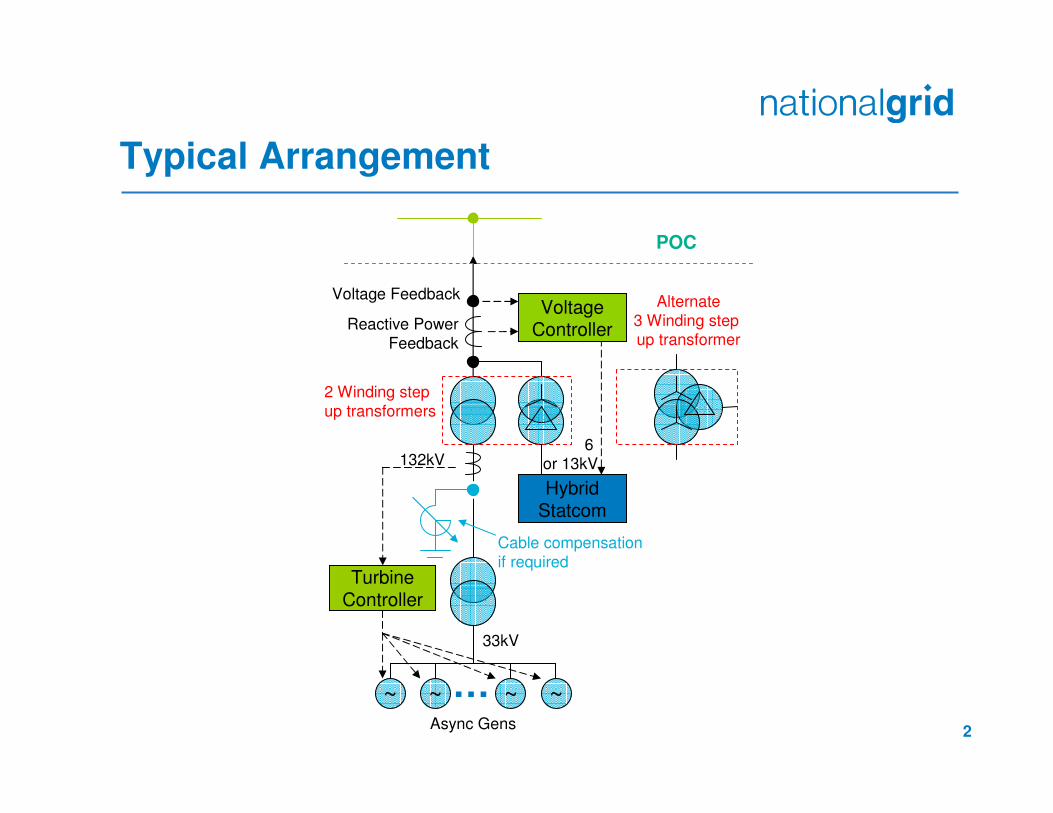
Typical Arrangement
33kV
132kV
~
TurbineController
Voltage Feedback
Reactive Power
Feedback
VoltageController
HybridStatcom
~ ~ ~…
POC
Cable compensation
if required
Async Gens
6 or 13kV
Alternate
3 Winding step up transformer
2 Winding step
up transformers

3
Typical Hybrid Statcom Operating Ranges
6 or 13kV
CB1 CB2 CB3 CB4Convertor
6 or 13kV
CB2CB1Convertor
Double switched capacitor / reactor
Single switched capacitor / reactor
100% Reactive Lead
(0.95 leading PF at
Rated MW)
100% Reactive Lead
(0.95 leading PF at
Rated MW)
100% Reactive Lead
(0.95 leading PF at
Rated MW)
100% Reactive Lead
(0.95 leading PF at
Rated MW)
Unity PF
Unity PF
CB2&4 Closed
CB2 Closed
All CB’s Open
CB1 Closed
CB1&3 Closed
All CB’s Open
CB2 Closed
CB1 Closed

4
Requirement for Continuous Dynamic Reactive Capability
� Scenarios where fast repeatable reactive power delivery is required
�Situations where multiple events cause rapid sequences
of voltage changes
�With increased asynchronous generation and the need to
facilitate higher flows it may be necessary to instigate
Power Oscillation Damping
5
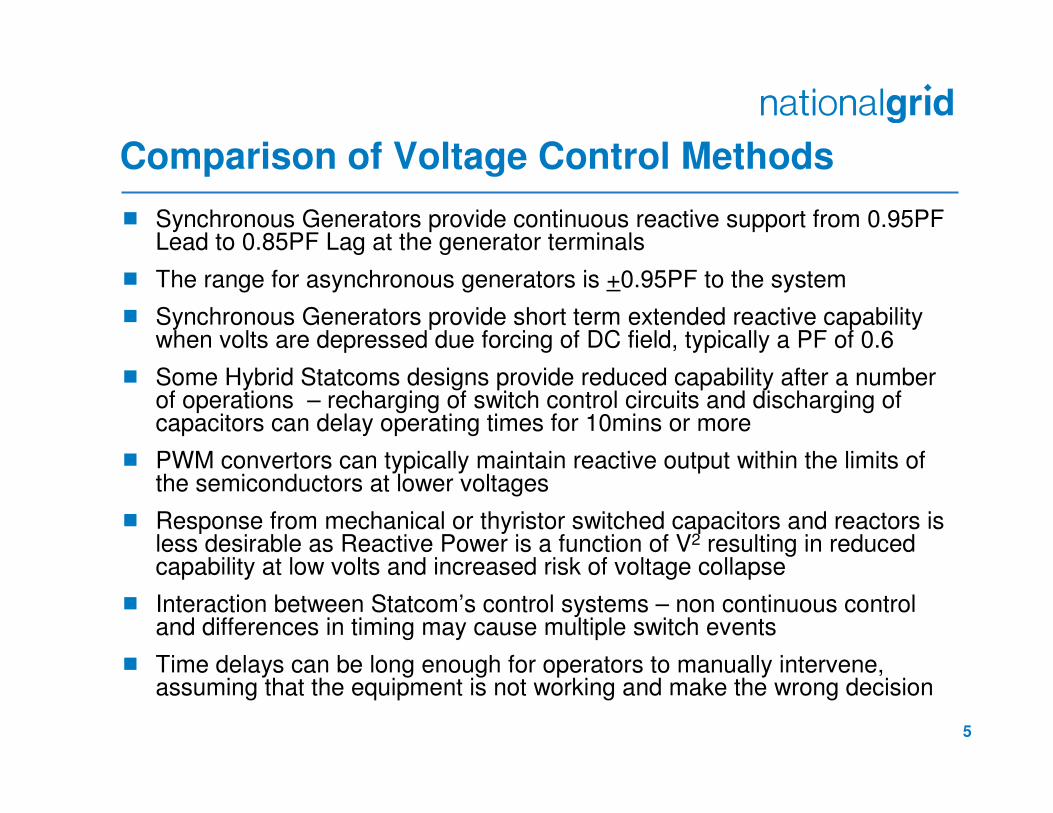
Comparison of Voltage Control Methods
� Synchronous Generators provide continuous reactive support from 0.95PF Lead to 0.85PF Lag at the generator terminals
� The range for asynchronous generators is +0.95PF to the system
� Synchronous Generators provide short term extended reactive capability when volts are depressed due forcing of DC field, typically a PF of 0.6
� Some Hybrid Statcoms designs provide reduced capability after a number of operations – recharging of switch control circuits and discharging of capacitors can delay operating times for 10mins or more
� PWM convertors can typically maintain reactive output within the limits of the semiconductors at lower voltages
� Response from mechanical or thyristor switched capacitors and reactors is less desirable as Reactive Power is a function of V2 resulting in reduced capability at low volts and increased risk of voltage collapse
� Interaction between Statcom’s control systems – non continuous control and differences in timing may cause multiple switch events
� Time delays can be long enough for operators to manually intervene, assuming that the equipment is not working and make the wrong decision
6
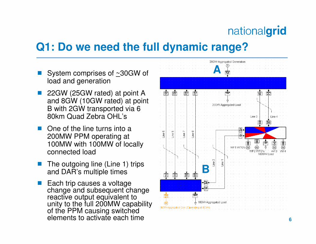
Q1: Do we need the full dynamic range?
� System comprises of ~30GW of load and generation
� 22GW (25GW rated) at point A and 8GW (10GW rated) at point B with 2GW transported via 6 80km Quad Zebra OHL’s
� One of the line turns into a 200MW PPM operating at 100MW with 100MW of locally connected load
� The outgoing line (Line 1) trips and DAR’s multiple times
� Each trip causes a voltage change and subsequent change reactive output equivalent to unity to the full 200MW capability of the PPM causing switched elements to activate each time
A
B

7
Single Circuit Turn In Scenario
1. Prior to the circuit tripping the voltage in the substation is 0.986pu despite the voltage control reference of the PPM being set to 1.005pu.
2. Under these conditions the PPM produces 61MVAr to prop up the volts. NB the local load is at unity PF and does require VAr support. This is virtually the full capability.
3. Circuit trips and the voltage rises (This can occur on multiple occasions due to DAR action).
4. Assuming the switches in the Statcom operate as required the device output drops to 3MVAr’s (Vref of 1.0025 the MVAr output drops to -2.63MVAr)
5. Placing another generator between the substation and the load (or in the substation) and tripping the line between generator and load causes a reversal of real and reactive power flow. This creates a greater change in reactive power from the PPM and gives full range movement for 4% droop setting
Note: The problem is scale-able and applicable to both larger and smaller PPMs, transmission and distribution connected in England, Scotland and Wales
400kVS/S
~
200MW W/F Producing 100MW 61MVAr 1.005Vref with 2% Slope400kV B/B is 0.986pu(NB 1.0025Vref gives 55MVAr)
100MW Unity PF Load
320MW 98MVArQuad Zebra turn in80km
320MW 161MVAr CB opens and load is lost B/B is now 1.004pu10km

8
Q2: Do we need generic continuous, repeated Capability?
DAR Operation:
1. DAR will automatically reclose tripped circuit breakers after the ‘Dead Time’ has expired, typically 3-20seconds. Dead time allows ionized gas to blow away or ash to fall away.
2. On re-establishing the circuit a second timer starts, this period is known as the ‘Reclaim Time’. Faults during this period will cause a second trip which will lock out the breaker. This period typically lasts 15-20seconds. The Reclaim Time allows the insulation medium in the breaker (Oil / SF6) time to recover.
3. If faults repeatedly occur after the Reclaim Time, operator intervention is required to lock the line out. This is the worst case scenario for the Hybrid Statcom. Further operator interventions i.e. switching operations, may require additional actions from the Hybrid Statcoms.
Scenarios which cause DAR Operation include:
� Lightning Storm Travelling up a Line
� Debris on the line e.g. Polythene sheet
� High winds causing conductor clashing
9
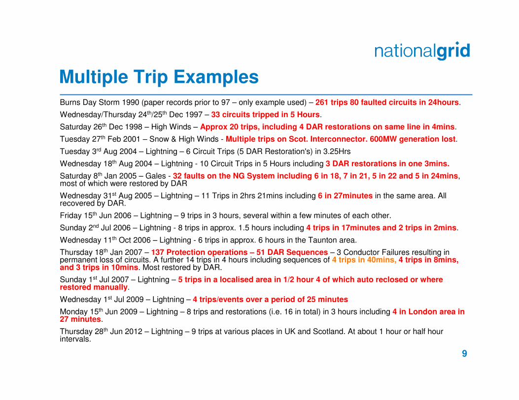
Multiple Trip ExamplesBurns Day Storm 1990 (paper records prior to 97 – only example used) – 261 trips 80 faulted circuits in 24hours.
Wednesday/Thursday 24th/25th Dec 1997 – 33 circuits tripped in 5 Hours.
Saturday 26th Dec 1998 – High Winds – Approx 20 trips, including 4 DAR restorations on same line in 4mins.
Tuesday 27th Feb 2001 – Snow & High Winds - Multiple trips on Scot. Interconnector. 600MW generation lost.
Tuesday 3rd Aug 2004 – Lightning – 6 Circuit Trips (5 DAR Restoration's) in 3.25Hrs
Wednesday 18th Aug 2004 – Lightning - 10 Circuit Trips in 5 Hours including 3 DAR restorations in one 3mins.
Saturday 8th Jan 2005 – Gales - 32 faults on the NG System including 6 in 18, 7 in 21, 5 in 22 and 5 in 24mins, most of which were restored by DAR
Wednesday 31st Aug 2005 – Lightning – 11 Trips in 2hrs 21mins including 6 in 27minutes in the same area. All recovered by DAR.
Friday 15th Jun 2006 – Lightning – 9 trips in 3 hours, several within a few minutes of each other.
Sunday 2nd Jul 2006 – Lightning - 8 trips in approx. 1.5 hours including 4 trips in 17minutes and 2 trips in 2mins.
Wednesday 11th Oct 2006 – Lightning - 6 trips in approx. 6 hours in the Taunton area.
Thursday 18th Jan 2007 – 137 Protection operations – 51 DAR Sequences – 3 Conductor Failures resulting in permanent loss of circuits. A further 14 trips in 4 hours including sequences of 4 trips in 40mins, 4 trips in 8mins, and 3 trips in 10mins. Most restored by DAR.
Sunday 1st Jul 2007 – Lightning – 5 trips in a localised area in 1/2 hour 4 of which auto reclosed or where restored manually.
Wednesday 1st Jul 2009 – Lightning – 4 trips/events over a period of 25 minutes
Monday 15th Jun 2009 – Lightning – 8 trips and restorations (i.e. 16 in total) in 3 hours including 4 in London area in 27 minutes.
Thursday 28th Jun 2012 – Lightning – 9 trips at various places in UK and Scotland. At about 1 hour or half hour intervals.

10
Interaction Between Hybrid Statcom’s
132kV
Voltage Feedback
Reactive Power
Feedback
VoltageController
HybridStatcom 132kV
Voltage Feedback
Reactive Power
Feedback
VoltageController
HybridStatcom
POC275 or 400kV
NG Substation
WTGsWTGs
6 or 13kV
6 or 13kV
6 or 13kV
CB1 CB2 CB3 CB4Convertor
6 or 13kV
CB2CB1Convertor
Single switched capacitor / reactor
11
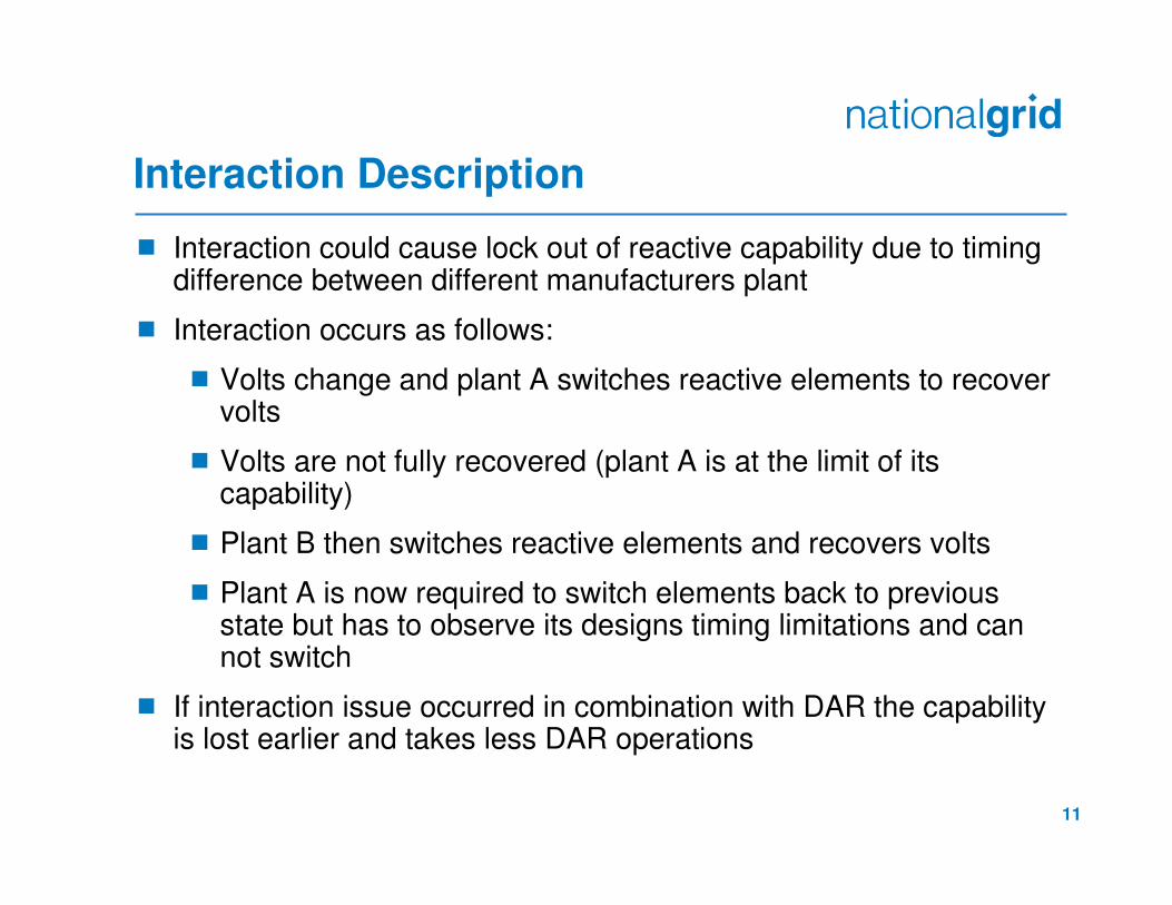
Interaction Description
� Interaction could cause lock out of reactive capability due to timing difference between different manufacturers plant
� Interaction occurs as follows:
� Volts change and plant A switches reactive elements to recover volts
� Volts are not fully recovered (plant A is at the limit of its capability)
� Plant B then switches reactive elements and recovers volts
� Plant A is now required to switch elements back to previous state but has to observe its designs timing limitations and can not switch
� If interaction issue occurred in combination with DAR the capability is lost earlier and takes less DAR operations
12
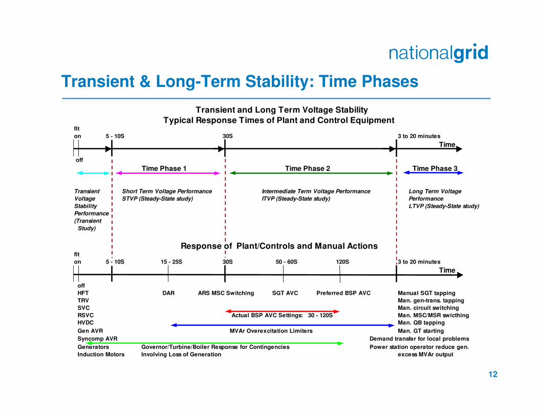
Transient & Long-Term Stability: Time Phases
Transient and Long Term Voltage Stability
Typical Response Times of Plant and Control Equipment flt
on 5 - 10S 30S 3 to 20 minutes
Time
off
Time Phase 1 Time Phase 2 Time Phase 3
Transient Short Term Voltage Performance Intermediate Term Voltage Performance Long Term Voltage
Voltage STVP (Steady-State study) ITVP (Steady-State study) Performance
Stability LTVP (Steady-State study)
Performance
(Transient
Study)
Response of Plant/Controls and Manual Actionsflt
on 5 - 10S 15 - 25S 30S 50 - 60S 120S 3 to 20 minutes
Time
off
HFT DAR ARS MSC Switching SGT AVC Preferred BSP AVC Manual SGT tapping
TRV Man. gen-trans. tapping
SVC Man. circuit switching
RSVC Actual BSP AVC Settings: 30 - 120S Man. MSC/MSR swicthing
HVDC Man. QB tapping
Gen AVR MVAr Overexcitation Limiters Man. GT starting
Syncomp AVR Demand transfer for local problems
Generators Governor/Turbine/Boiler Response for Contingencies Power station operator reduce gen.
Induction Motors Involving Loss of Generation excess MVAr output
13
Current Position
Panel’s previous recommendation:
� Define “continuous” in the current Grid Code to mean a
minimum of 15 seconds (close-open-close) and 2 seconds (capacitor discharge) for second switching
operation with no specified requirement for a third
switching operation

14
Next Steps
� National Grid to develop draft consultation incorporating views of interested stakeholders
� Input from manufacturers and developers required
�Panel Members are asked if they would like to have a
direct input
�Alternative approach is to take the issue to working group
Appendix – Grid Code Requirements

16
Control Arrangements CC.6.3.6 (b)
Each:
(i) Onshore Generating Unit; or,
(ii) Onshore DC Converter (with a Completion Date on or after 1 April 2005 excluding current source technologies); or
(iii) Onshore Power Park Module in England and Wales with a Completion Date on or after 1 January 2006; or,
(iv) Onshore Power Park Module in Scotland irrespective of Completion Date; or,
(v) Offshore Generating Unit at a Large Power Station, Offshore DC Converter at a Large Power Station or Offshore Power Park Module at a Large Power Station which provides a reactive range beyond the minimum requirements specified in CC.6.3.2(e) (iii),
must be capable of contributing to voltage control by continuous changes to the Reactive Power supplied to the National Electricity Transmission System or the User System in which it is Embedded.
17
Existing Grid Code Requirements
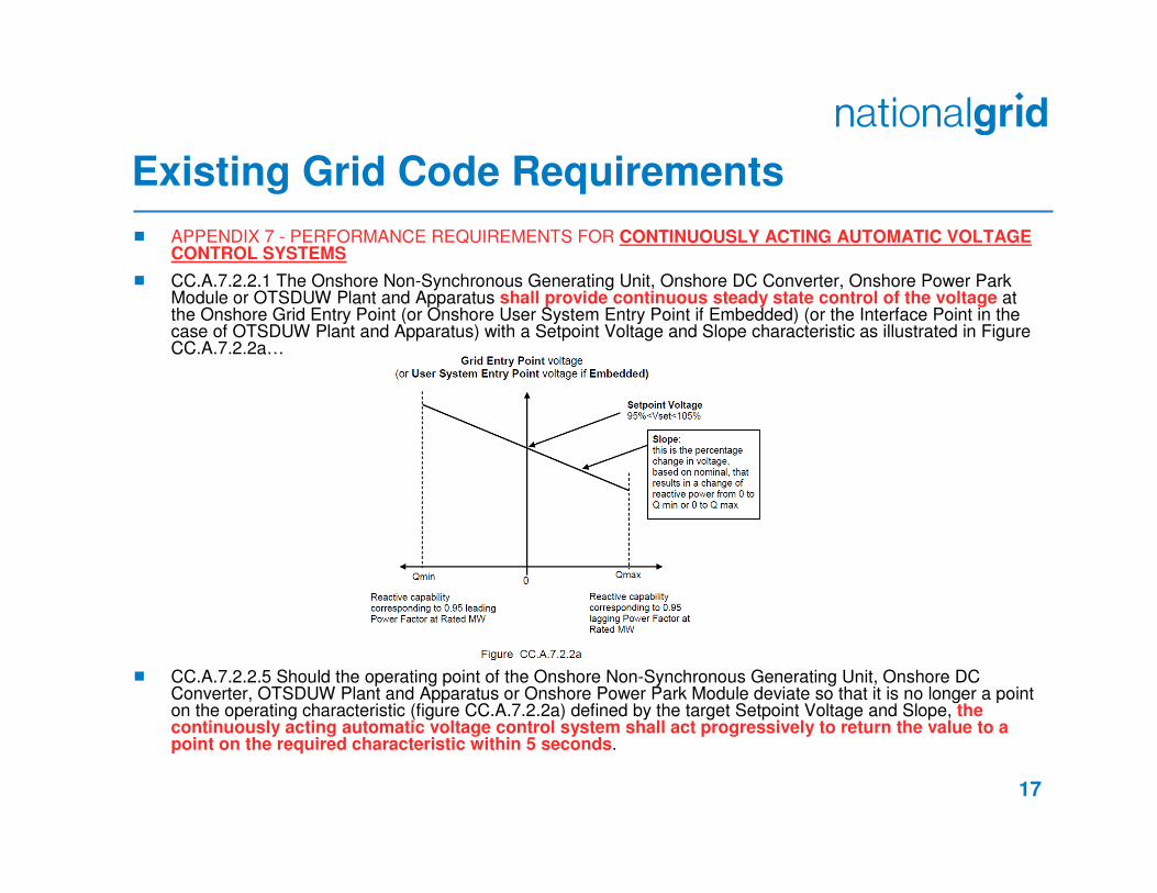
� APPENDIX 7 - PERFORMANCE REQUIREMENTS FOR CONTINUOUSLY ACTING AUTOMATIC VOLTAGE CONTROL SYSTEMS
� CC.A.7.2.2.1 The Onshore Non-Synchronous Generating Unit, Onshore DC Converter, Onshore Power Park Module or OTSDUW Plant and Apparatus shall provide continuous steady state control of the voltage at the Onshore Grid Entry Point (or Onshore User System Entry Point if Embedded) (or the Interface Point in the case of OTSDUW Plant and Apparatus) with a Setpoint Voltage and Slope characteristic as illustrated in Figure CC.A.7.2.2a…
� CC.A.7.2.2.5 Should the operating point of the Onshore Non-Synchronous Generating Unit, Onshore DC Converter, OTSDUW Plant and Apparatus or Onshore Power Park Module deviate so that it is no longer a point on the operating characteristic (figure CC.A.7.2.2a) defined by the target Setpoint Voltage and Slope, the continuously acting automatic voltage control system shall act progressively to return the value to a point on the required characteristic within 5 seconds.
18
Existing Grid Code Requirements
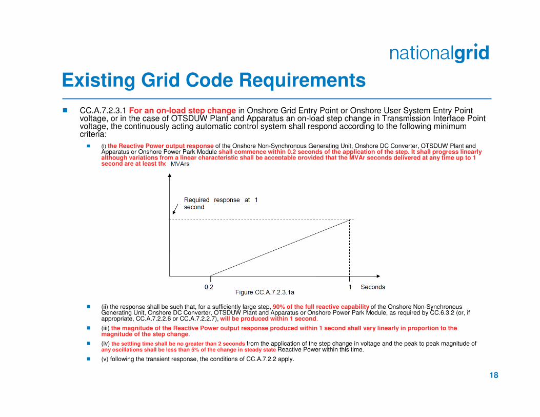
� CC.A.7.2.3.1 For an on-load step change in Onshore Grid Entry Point or Onshore User System Entry Point voltage, or in the case of OTSDUW Plant and Apparatus an on-load step change in Transmission Interface Point voltage, the continuously acting automatic control system shall respond according to the following minimum criteria:
� (i) the Reactive Power output response of the Onshore Non-Synchronous Generating Unit, Onshore DC Converter, OTSDUW Plant and Apparatus or Onshore Power Park Module shall commence within 0.2 seconds of the application of the step. It shall progress linearly although variations from a linear characteristic shall be acceptable provided that the MVAr seconds delivered at any time up to 1 second are at least those that would result from the response shown in figure CC.A.7.2.3.1a.
� (ii) the response shall be such that, for a sufficiently large step, 90% of the full reactive capability of the Onshore Non-Synchronous Generating Unit, Onshore DC Converter, OTSDUW Plant and Apparatus or Onshore Power Park Module, as required by CC.6.3.2 (or, if appropriate, CC.A.7.2.2.6 or CC.A.7.2.2.7), will be produced within 1 second.
� (iii) the magnitude of the Reactive Power output response produced within 1 second shall vary linearly in proportion to the magnitude of the step change.
� (iv) the settling time shall be no greater than 2 seconds from the application of the step change in voltage and the peak to peak magnitude ofany oscillations shall be less than 5% of the change in steady state Reactive Power within this time.
� (v) following the transient response, the conditions of CC.A.7.2.2 apply.

19
Existing Grid Code Requirements
CC 6.3.2 – Reactive Capability Chart
For Asynchronous Generation
CC 6.3.4 – Reactive Capability
vs Volts
20
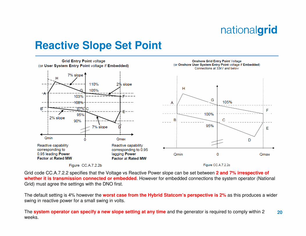
Reactive Slope Set Point
Grid code CC.A.7.2.2 specifies that the Voltage vs Reactive Power slope can be set between 2 and 7% irrespective of whether it is transmission connected or embedded. However for embedded connections the system operator (National
Grid) must agree the settings with the DNO first.
The default setting is 4% however the worst case from the Hybrid Statcom’s perspective is 2% as this produces a wider swing in reactive power for a small swing in volts.
The system operator can specify a new slope setting at any time and the generator is required to comply within 2
weeks.


![WCE 2017, July 5-7, 2017, London, U.K. Rail Power ... · speed and high power railways systems, ... (SVCs) or static synchronous compensators (STATCOMs) [5]. The main disadvantage](https://static.fdocuments.in/doc/165x107/5ae268ea7f8b9a7b218be9ee/wce-2017-july-5-7-2017-london-uk-rail-power-and-high-power-railways-systems.jpg)


![[Public] ABB Operational Experiences of STATCOMs for Wind Parks](https://static.fdocuments.in/doc/165x107/577c7d581a28abe0549e69e4/public-abb-operational-experiences-of-statcoms-for-wind-parks.jpg)