
Hybrid Rotor Compression for Multiphase and Liquids-Rich ... Library/Research/Oil-Gas/Natural...
22
Final Report to Hybrid Rotor Compression for Multiphase and Liquids-Rich Wellhead Production Applications OsComp Systems Inc. – 11123.15.Final September 30, 2014 Jeremy Pitts 4140 World Houston Parkway, Suite 100 Houston, TX 77032 (281)727-0250 [email protected]
Transcript of Hybrid Rotor Compression for Multiphase and Liquids-Rich ... Library/Research/Oil-Gas/Natural...
Final Report to
Hybrid Rotor Compression for Multiphase and Liquids-Rich Wellhead
Production Applications
OsComp Systems Inc. – 11123.15.Final
September 30, 2014
Jeremy Pitts 4140 World Houston Parkway, Suite 100
Houston, TX 77032
(281)727-0250
LEGAL NOTICE
This report was prepared by OsComp Systems, Inc. as an account of work sponsored by
the Research Partnership to Secure Energy for America, RPSEA. Neither RPSEA members of
RPSEA, the National Energy Technology Laboratory, the U.S. Department of Energy, nor any
person acting on behalf of any of the entities:
a. MAKES ANY WARRANTY OR REPRESENTATION, EXPRESS OR IMPLIED WITH RESPECT TO ACCURACY, COMPLETENESS, OR USEFULNESS OF THE INFORMATION CONTAINED IN THIS DOCUMENT, OR THAT THE USE OF ANY INFORMATION, APPARATUS, METHOD, OR PROCESS DISCLOSED IN THIS DOCUMENT MAY NOT INFRINGE PRIVATELY OWNED RIGHTS, OR
b. ASSUMES ANY LIABILITY WITH RESPECT TO THE USE OF, OR FOR ANY AND ALL DAMAGES RESULTING FROM THE USE OF, ANY INFORMATION, APPARATUS, METHOD, OR PROCESS DISCLOSED IN THIS DOCUMENT.
THIS IS A FINAL REPORT. THE DATA, CALCULATIONS, INFORMATION, CONCLUSIONS,
AND/OR RECOMMENDATIONS REPORTED HEREIN ARE THE PROPERTY OF THE U.S.
DEPARTMENT OF ENERGY.
REFERENCE TO TRADE NAMES OR SPECIFIC COMMERCIAL PRODUCTS,
COMMODITIES, OR SERVICES IN THIS REPORT DOES NOT REPRESENT OR
CONSTIITUTE AND ENDORSEMENT, RECOMMENDATION, OR FAVORING BY RPSEA OR
ITS CONTRACTORS OF THE SPECIFIC COMMERCIAL PRODUCT, COMMODITY, OR
SERVICE.

THIS PAGE LEFT INTENTIONALLY BLANK
Abstract This paper presents the results of work performed under RPSEA’s Small Producer Program, Subcontract
number 11125-15. The award was presented to OsComp Systems to continue development of a new
compressor concept that could be used for small producers to operate wet gas and multiphase wells
without the need for wellhead separation.
Over the course of the project, two successive compressor prototypes were developed and tested. The
testing shows very strong conceptual proof of concept, with the compressor being able to successfully
accommodate multiphase flow through the machine without experiencing hydrolock conditions
expected with conventional compression technologies. Challenges were encountered during testing
with achieving sufficient reliability of the machine, and so the initially planned field trials were pushed
out in favor of additional lab testing and redesign efforts. The project culminated with significant strides
made in working through many of the problematic components and subsystems of the compressor. In
addition, private funds have been secured to allow development to continue, the successful completion
of which will lead to future commercialization of the technology.
1. Table of Contents Abstract ......................................................................................................................................................... 4
2. Table of Figures ..................................................................................................................................... 6
3. Executive Summary ............................................................................................................................... 7
4. Introduction .......................................................................................................................................... 9
5. Technology Introduction ....................................................................................................................... 9
5.1. Thermodynamic Enhancements ................................................................................................... 9
5.2. Mechanical Design ...................................................................................................................... 10
5.3. Multiphase Capabilities ............................................................................................................... 11
6. Project Summary ................................................................................................................................. 13
6.1. “Unit 2” Design............................................................................................................................ 13
6.2. “Unit 2” Testing ........................................................................................................................... 13
6.3. “Unit 3” Design............................................................................................................................ 13
6.4. “Unit 3” Testing ........................................................................................................................... 13
6.5. Evolution of OsComp .................................................................................................................. 13
7. Design Review ..................................................................................................................................... 14
7.1. Unit 2 ........................................................................................................................................... 14
7.2. Unit 3 ........................................................................................................................................... 14
8. Test Results ......................................................................................................................................... 15
8.1. Unit 2 ........................................................................................................................................... 15
8.2. Unit 3 ........................................................................................................................................... 19
9. Technology Transfer Activities ............................................................................................................ 21
10. Next Steps and Conclusion .............................................................................................................. 22
2. Table of Figures Figure 1 - PV plot of adiabatic versus isothermal compression .................................................................. 10
Figure 2 - Schematic of OsComp compression process .............................................................................. 11
Figure 3 - Schematic of conventional versus OsComp wet gas stream ...................................................... 12
Figure 4 - Wellhead with conventional technology versus OsComp technology ....................................... 12
Figure 5 - Summary of design changes between unit 2 and unit 3............................................................. 15
Figure 6 - Fractured spring from unit 2 4 hour test .................................................................................... 17
Figure 7 - Results of unit 2 24 hour test ...................................................................................................... 18
Figure 8 - Unit 2 rotor lip failure ................................................................................................................. 19
Figure 9 - Initial low pressure low speed test run of unit 3 prototype ....................................................... 20
Figure 10 - Summary of testing hours for successive compressor prototypes ........................................... 21
3. Executive Summary OsComp Systems received Subaward number 11123-15 through RPSEA’s Small Producer Program to
continue development of a wet gas compressor technology. The project commenced in January 2013
and concluded in September 2014.
The focus of the project was to develop and test OsComp’s new compression technology. The
technology can best be explained by focusing on three aspects— thermodynamics, mechanical design,
and multiphase capabilities. The thermodynamics of compression are such that gas heats up as it is
compressed. The hotter the gas gets, the harder it becomes to compress, which further leads to more
and more heat generation. This effect realistically limits most compressor technologies to compression
ratios of 5:1. OsComp has developed a cooling technology in which an atomized liquid coolant is
injected directly into the compression chamber. The manner of injection results in extremely rapid heat
transfer from the gas to the liquid, keeping the gas cool. This cooling effect not only makes the
compression process more efficient, but also allows compression ratios of 40:1 or higher.
Conventional compression equipment is not capable of utilizing this type of cooling technology because
liquids cannot be tolerated in the compression chamber. OsComp’s unique hybrid rotary design allows
liquids to be swept out of the compression chamber, eliminating the hydrolock conditions seen with
liquids in traditional compressors. This unique mechanical design not only enables the thermodynamic
enhancements, but also allows for compression of wet gas, or gas that contains liquid content.
At many natural gas wellheads, liquids—typically heavier hydrocarbons and water—are present in the
gas stream. In fact, with the recent pricing trends with natural gas and other hydrocarbons, wet gas is
actually more desirable to producers due to the higher value of the liquid hydrocarbons. However, since
traditional compressors cannot accommodate liquids, the gas and liquid have to be separated at the
wellhead and dealt with separately. This presents significantly higher costs to operators. With
OsComp’s technology, the gas and liquid can go directly from the wellhead through the compressor and
on to a single multiphase pipeline, leading to a centralized processing facility and dramatically lower
costs.
Over the course of this 21 month project, the OsComp team has developed two successive prototypes of
its compressor technology, each improving on the last. The first prototype developed under this project,
known as “unit 2”, was designed and built at the start of the project, coming online for testing in May
2013. Testing of the unit verified the conceptual breakthroughs of the design, with multiphase flows
being successfully accommodated and the cooling technology working well. However, some design
issues were encountered, leading to the decision that additional lab testing would need to be conducted
before entering into field trials and that a new design would need to be completed to correct for some
of the issues experienced with unit 2.
The unit 3 design was developed over the fall of 2013 and built through the winter, coming online for
testing in April 2014. Unit 3 initially appeared much more robust than unit 2, performing well in early
tests and continuing to show further proof of the technological breakthroughs inherent to the design.
However, issues with reliability continued to plague the testing efforts, with tests under more extreme

conditions or for extended time periods typically leading to some type of failure. It was determined that
the complexity of the system was too high to expect to be able to improve on this performance when
only testing at a full system level, so a new plan of component and subsystem level testing was put into
place.
This component level testing proved to be very successful, with many more hours of testing successfully
completed and performance improved on several critical subsystems. Testing at the component level
will continue after the culmination of the RPSEA subcontract, with plans for further units and eventual
field trials and commercialization to follow.
A deep understanding of the challenges associated with developing a breakthrough industrial machinery
technology has been developed over the course of the project. While the project did not progress as far
as initially scoped, the current understanding of the problem allows for a much more accurate
prediction of future success of the development. The team remains confident in a successful outcome,
with private funding in place to help continue development into the future.
4. Introduction OsComp Systems sought out to design a compressor that could help to make the production and
transportation of natural gas more cost effective for producers, particularly small ones. Along the way,
the technology has evolved into a revolutionary concept that enables dramatic simplification of
wellhead infrastructure, lower capital and operating costs, and significant reductions in environmental
impact.
It was with the early stages of this vision in mind that OsComp applied for and received Subaward
number 11123-15 through the Research Partnership to Secure Energy for America (RPSEA) and its Small
Producer Program. The work performed under that contract kicked off in January 2013.
This paper documents the work performed under this RPSEA subcontract during its 21-month period.
The paper will first present an introduction to OsComp’s technology, followed by an overview of the key
progress made during the project. It will then review some key elements of the design of the prototypes
developed under the contract and results of the testing conducted. The paper concludes with a review
of technology transfer activities performed under the contract and next steps for the further
development and commercialization of the technology.
5. Technology Introduction There are three key components of OsComp’s compression technology—thermodynamic
enhancements, mechanical design, and multiphase capabilities.
5.1. Thermodynamic Enhancements In a basic compression process, gas temperatures rise as the gas is compressed. In this scenario,
temperatures rise quickly during the compression process. As temperatures rise, compression of the
gas becomes more and more energy intensive. On the opposite end of the spectrum, an isothermal
compression process is one in which the temperature of the gas is held constant during compression.
This requires offloading heat into the outside environment to keep internal temperatures low. The
energy required for each of these compression processes can be represented graphically in a pressure-
volume (PV) plot, in which the work required for compression is represented by the area under the
curve.
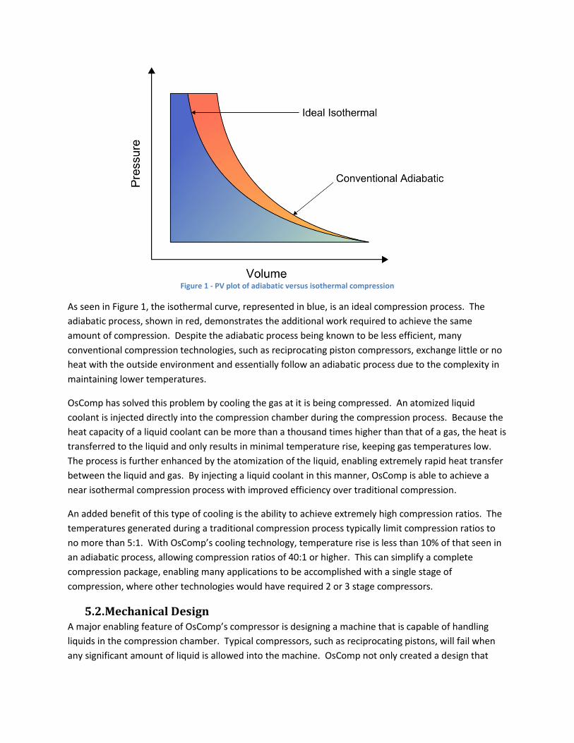
Figure 1 - PV plot of adiabatic versus isothermal compression
As seen in Figure 1, the isothermal curve, represented in blue, is an ideal compression process. The
adiabatic process, shown in red, demonstrates the additional work required to achieve the same
amount of compression. Despite the adiabatic process being known to be less efficient, many
conventional compression technologies, such as reciprocating piston compressors, exchange little or no
heat with the outside environment and essentially follow an adiabatic process due to the complexity in
maintaining lower temperatures.
OsComp has solved this problem by cooling the gas at it is being compressed. An atomized liquid
coolant is injected directly into the compression chamber during the compression process. Because the
heat capacity of a liquid coolant can be more than a thousand times higher than that of a gas, the heat is
transferred to the liquid and only results in minimal temperature rise, keeping gas temperatures low.
The process is further enhanced by the atomization of the liquid, enabling extremely rapid heat transfer
between the liquid and gas. By injecting a liquid coolant in this manner, OsComp is able to achieve a
near isothermal compression process with improved efficiency over traditional compression.
An added benefit of this type of cooling is the ability to achieve extremely high compression ratios. The
temperatures generated during a traditional compression process typically limit compression ratios to
no more than 5:1. With OsComp’s cooling technology, temperature rise is less than 10% of that seen in
an adiabatic process, allowing compression ratios of 40:1 or higher. This can simplify a complete
compression package, enabling many applications to be accomplished with a single stage of
compression, where other technologies would have required 2 or 3 stage compressors.
5.2. Mechanical Design A major enabling feature of OsComp’s compressor is designing a machine that is capable of handling
liquids in the compression chamber. Typical compressors, such as reciprocating pistons, will fail when
any significant amount of liquid is allowed into the machine. OsComp not only created a design that

allows liquids to pass through, but also produced an elegantly simple machine with high power density,
fewer moving parts, and lower vibration and noise.
OsComp’s design is a hybrid rotary design as seen in Figure 2. A concentrically spinning, balanced rotor
spins in line with the main drive shaft. A vertically moving vane is driven by external cams such that it
maintains contact with the rotor as all times, sealing between the high and low pressure portions of the
chamber. As seen in Figure 2, gas (shown in blue) enters the compressor at the bottom left. The
leftmost image represents the maximum gas volume. As the rotor sweeps around counterclockwise, the
gas is compressed between the rotor and vane. Once internal pressures exceed those of the
downstream piping, valves at the lower right of the compressor open and allow the gas to exhaust.
Figure 2 - Schematic of OsComp compression process
The sweeping motion of the rotor ensures that all of the liquid is fully exhausted from the cylinder
during each rotation, preventing buildup of liquid and eventual hydrolock experienced with
conventional pistons compressors. Special valves are designed with extremely high orifice volume,
allowing the mixed phase fluid to easily exhaust. In addition, the location of the outlet at the bottom of
the compressor ensures that gravity will help to force liquids from the chamber.
This design not only enables liquid injection and the thermodynamic benefits described in §5.1, but has
a number of other key features. The rotary nature of the machine allows the compression chamber to
be built directly around the main drive shaft, dramatically reducing the size of machine required for a
given compression process as compared to piston type machines with the compression occurring
normal to the drive shaft. This also simplifies the design and number of moving parts since no motion
transferring components such as tie rods are required, ultimately resulting in lower costs and improved
reliability. The balanced nature of the rotary motion also ensures low vibration and noise during
operation.
5.3. Multiphase Capabilities A significant added benefit of the machine’s ability to pass liquids through the compression chamber is
that not only can cooling liquids be injected, but wet gas can also be passed directly through the
compressor without need for pre-separation.
Many natural gas wells produce not only gas, but also contain liquid hydrocarbons, such as propane and
butane, known as natural gas liquids (NGLs). These NGLs are of significantly higher value than the
primarily methane gaseous portion of the stream. Unfortunately, capturing these NGLs with
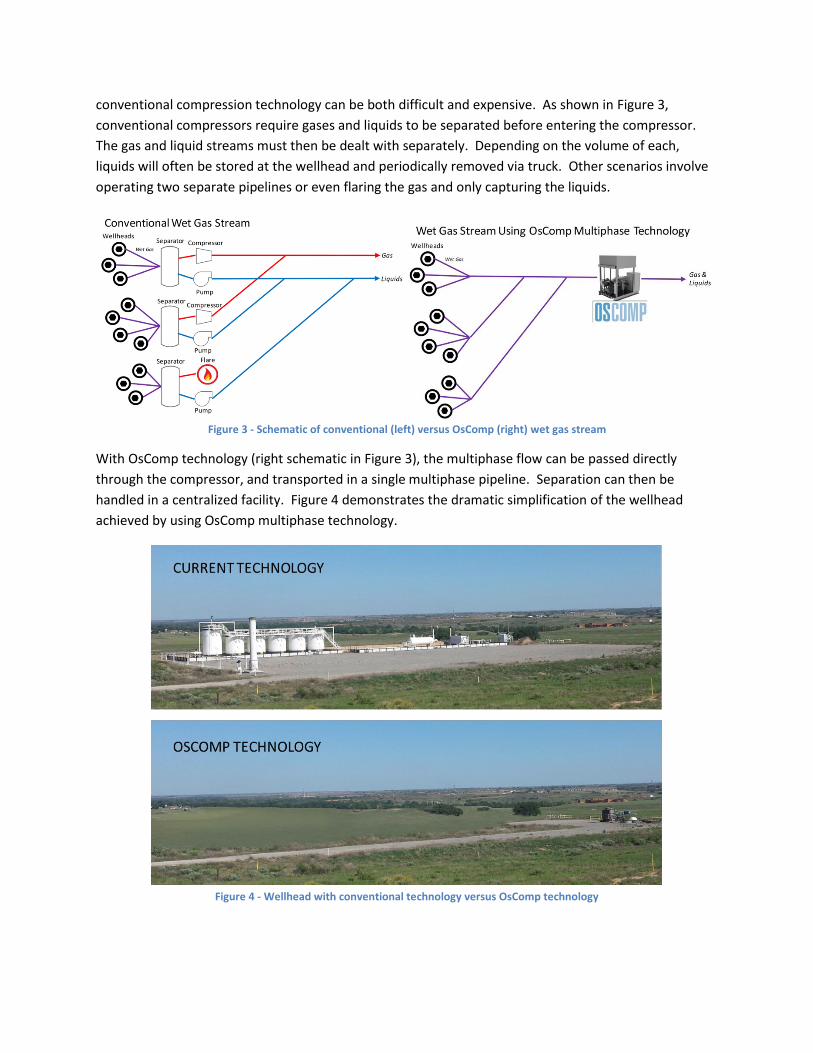
conventional compression technology can be both difficult and expensive. As shown in Figure 3,
conventional compressors require gases and liquids to be separated before entering the compressor.
The gas and liquid streams must then be dealt with separately. Depending on the volume of each,
liquids will often be stored at the wellhead and periodically removed via truck. Other scenarios involve
operating two separate pipelines or even flaring the gas and only capturing the liquids.
Figure 3 - Schematic of conventional (left) versus OsComp (right) wet gas stream
With OsComp technology (right schematic in Figure 3), the multiphase flow can be passed directly
through the compressor, and transported in a single multiphase pipeline. Separation can then be
handled in a centralized facility. Figure 4 demonstrates the dramatic simplification of the wellhead
achieved by using OsComp multiphase technology.
Figure 4 - Wellhead with conventional technology versus OsComp technology

6. Project Summary
6.1. “Unit 2” Design The project kicked off with the team building on initial compressor designs to create a “unit 2” design.
Manufacturing partners were engaged to machine all the components of the machine and it was then
built at OsComp’s Houston office and test facility.
6.2. “Unit 2” Testing In parallel with designing and building the unit 2 compressor, the OsComp team was also constructing a
fully featured test cell (outside the scope of the RPSEA project). Unit 2 testing began in May 2013 and
proceeded through the rest of the year. The unit remains operational in a limited capacity and testing
continues as time permits.
6.3. “Unit 3” Design Unit 2 testing revealed some promising results, however it also revealed some shortcomings in the
design. These shortcomings were used to inform a redesign effort for a new prototype, known as “unit
3.” Designs were released through late 2013 and early 2014. A manufacturing engineer added to the
team since the unit 2 build led the sourcing effort, helping to control processes and ensure parts were
delivered to specification. Unit 3 parts were received in-house and the compressor first assembled in
April 2014.
6.4. “Unit 3” Testing In addition to the build of unit 3, the OsComp team also completed a second, more functional test cell
(also outside the scope of the RPSEA project). Unit 3 testing commenced in the new test cell in April
2014 and has proceeded to date. A number of promising results have been achieved and will be
presented in §8.2.
6.5. Evolution of OsComp Over the course of this project, OsComp has made large strides as a company. The team has expanded
and added significant capabilities, with a senior manufacturing engineer, senior analysis engineer, senior
test engineer, and a test technician added to the team. An initial series A venture capital fundraising
round, raised before the start of this project, was augmented by a $6M series B investment in December
2013.
As a final mark of the company’s progress, a rebranding effort has been completed. OsComp Systems is
transforming into Hicor Technologies as of the completion of the project, to avoid confusion with a
spinoff company, also called OsComp, delivering virtual pipeline natural gas solutions.

7. Design Review
7.1. Unit 2 The unit 2 design was discussed in detail in a previous RPSEA deliverable, “Design Overview Update.”
Details of those improvements will be omitted here, however a summarized list of some of the key
design improvements are below:
Cast rotor casing and manifolds
Improved countersurfaces
Lubrication
Focus on materials
New rotor profile
Rotor endcaps
Smaller cam
7.2. Unit 3 The transition from the unit 2 to unit 3 design was much more subtle than the transition from unit 1 to
unit 2, but no less impactful. On the surface, unit 2 and unit 3 appear nearly identical, whereas unit 1
appears significantly different. However, much of the challenge in engineering and technology
development comes in getting the details right. In addition to the design updates, a massive effort was
put into working with suppliers to develop good manufacturing processes, ensuring that the parts are
delivered to print. Some of the noteworthy improvements in the unit 3 design are summarized below
and shown in Figure 5:
Increased focus on materials and coatings
Larger shaft for improved strength and bending resistance
New bearing arrangement to reduce axial play and improve rigidity
Hardened cams and yoke style cam follower
Graphite face seals bonded to stainless steel backing
Single piece valve cartridge with reduced clearance volume
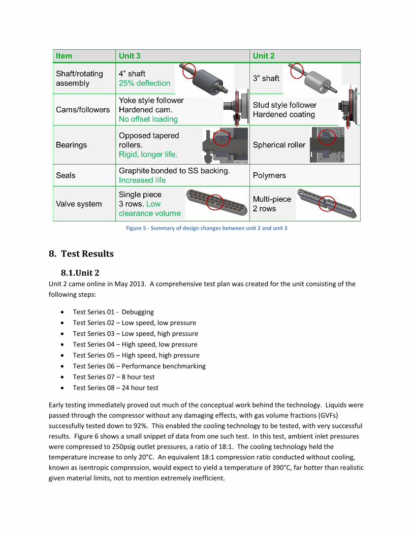
Figure 5 - Summary of design changes between unit 2 and unit 3
8. Test Results
8.1. Unit 2 Unit 2 came online in May 2013. A comprehensive test plan was created for the unit consisting of the
following steps:
Test Series 01 - Debugging
Test Series 02 – Low speed, low pressure
Test Series 03 – Low speed, high pressure
Test Series 04 – High speed, low pressure
Test Series 05 – High speed, high pressure
Test Series 06 – Performance benchmarking
Test Series 07 – 8 hour test
Test Series 08 – 24 hour test
Early testing immediately proved out much of the conceptual work behind the technology. Liquids were
passed through the compressor without any damaging effects, with gas volume fractions (GVFs)
successfully tested down to 92%. This enabled the cooling technology to be tested, with very successful
results. Figure 6 shows a small snippet of data from one such test. In this test, ambient inlet pressures
were compressed to 250psig outlet pressures, a ratio of 18:1. The cooling technology held the
temperature increase to only 20°C. An equivalent 18:1 compression ratio conducted without cooling,
known as isentropic compression, would expect to yield a temperature of 390°C, far hotter than realistic
given material limits, not to mention extremely inefficient.

Figure 6 - Test data showing temperature rise with 18:1 compression ratio
Unfortunately, early testing also showed that achieving the milestones laid out in the initial
development plan would be much more difficult than originally anticipated due to issues with
component failures and reliability. Test plans were revised to proceed through slow ramp up of speed
and pressure to identify maximum achievable specifications of the compressor.
Issues were identified with the shaft strength and bearing configuration that limited maximum
differential pressures to approximately 250psig. It was also established that the system ran better at
speeds around 700RPM as opposed to the full design speed of 900RPM. Further testing identified
various other design shortcomings discussed in the unit 3 design overview in §7.2.
After establishing performance limits, testing transitioned to a focus on reliability. A plan was
established for working towards a 24 hour continuous run test. The first step in that process was to
achieve a 4 hour continuous run test. The system ran fairly well for the first 2 hours, at which time one
of the two main drive springs fractured, immediately terminating the test (see Figure 7). Further
investigation identified that the vendor had not delivered a spring designed to achieve the cycle life
requested of them. The springs were replaced and the team moved forward with plans for a 24 hour
test.
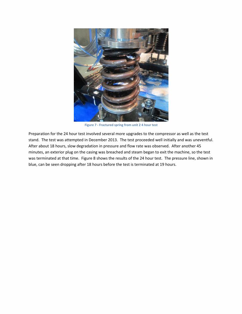
Figure 7 - Fractured spring from unit 2 4 hour test
Preparation for the 24 hour test involved several more upgrades to the compressor as well as the test
stand. The test was attempted in December 2013. The test proceeded well initially and was uneventful.
After about 18 hours, slow degradation in pressure and flow rate was observed. After another 45
minutes, an exterior plug on the casing was breached and steam began to exit the machine, so the test
was terminated at that time. Figure 8 shows the results of the 24 hour test. The pressure line, shown in
blue, can be seen dropping after 18 hours before the test is terminated at 19 hours.
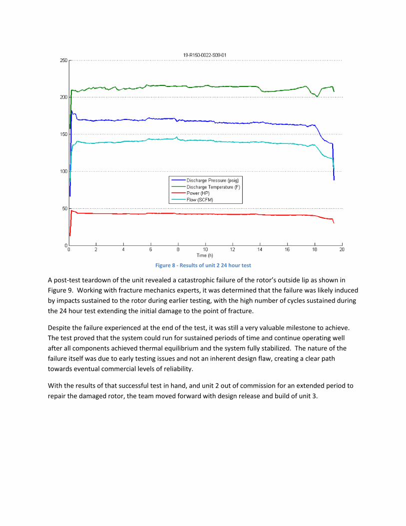
Figure 8 - Results of unit 2 24 hour test
A post-test teardown of the unit revealed a catastrophic failure of the rotor’s outside lip as shown in
Figure 9. Working with fracture mechanics experts, it was determined that the failure was likely induced
by impacts sustained to the rotor during earlier testing, with the high number of cycles sustained during
the 24 hour test extending the initial damage to the point of fracture.
Despite the failure experienced at the end of the test, it was still a very valuable milestone to achieve.
The test proved that the system could run for sustained periods of time and continue operating well
after all components achieved thermal equilibrium and the system fully stabilized. The nature of the
failure itself was due to early testing issues and not an inherent design flaw, creating a clear path
towards eventual commercial levels of reliability.
With the results of that successful test in hand, and unit 2 out of commission for an extended period to
repair the damaged rotor, the team moved forward with design release and build of unit 3.
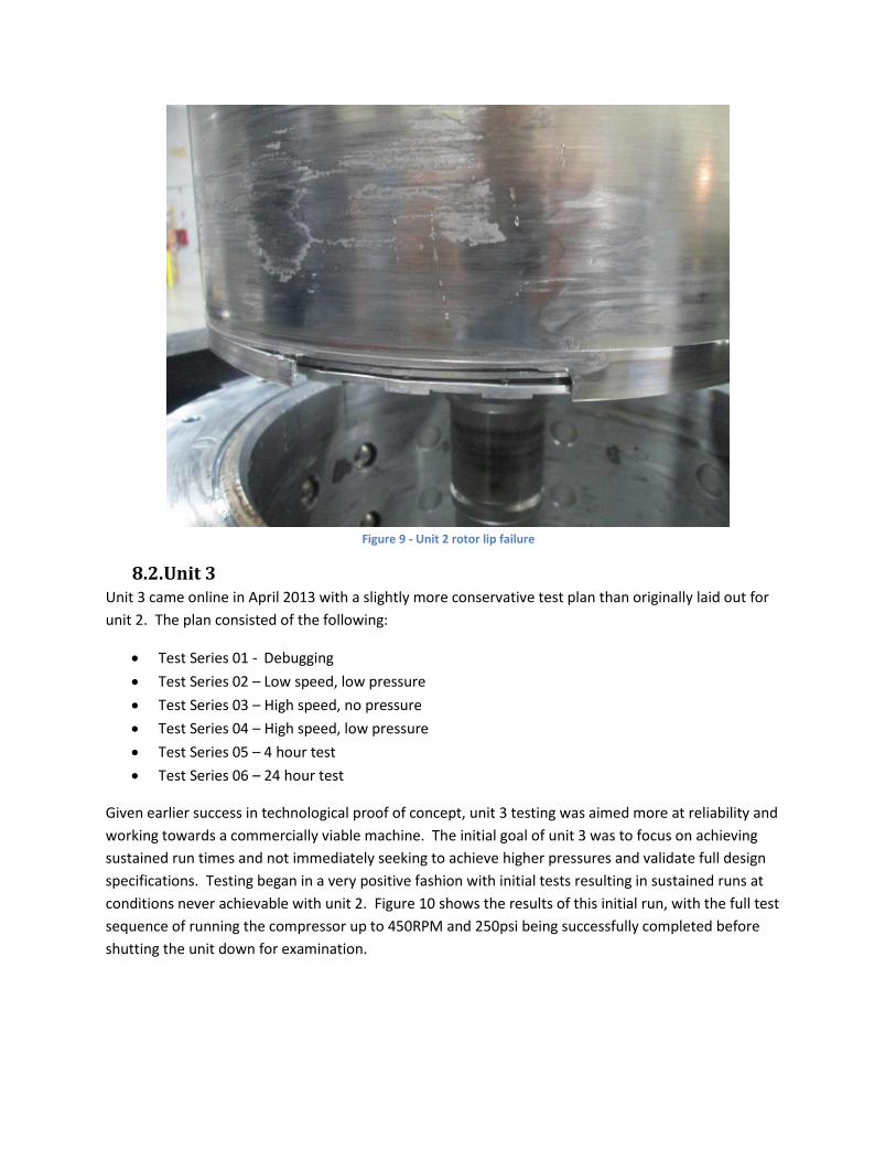
Figure 9 - Unit 2 rotor lip failure
8.2. Unit 3 Unit 3 came online in April 2013 with a slightly more conservative test plan than originally laid out for
unit 2. The plan consisted of the following:
Test Series 01 - Debugging
Test Series 02 – Low speed, low pressure
Test Series 03 – High speed, no pressure
Test Series 04 – High speed, low pressure
Test Series 05 – 4 hour test
Test Series 06 – 24 hour test
Given earlier success in technological proof of concept, unit 3 testing was aimed more at reliability and
working towards a commercially viable machine. The initial goal of unit 3 was to focus on achieving
sustained run times and not immediately seeking to achieve higher pressures and validate full design
specifications. Testing began in a very positive fashion with initial tests resulting in sustained runs at
conditions never achievable with unit 2. Figure 10 shows the results of this initial run, with the full test
sequence of running the compressor up to 450RPM and 250psi being successfully completed before
shutting the unit down for examination.
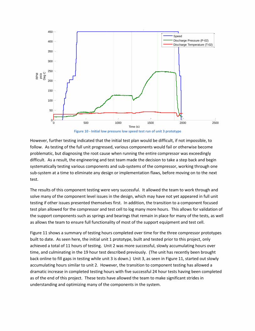
Figure 10 - Initial low pressure low speed test run of unit 3 prototype
However, further testing indicated that the initial test plan would be difficult, if not impossible, to
follow. As testing of the full unit progressed, various components would fail or otherwise become
problematic, but diagnosing the root cause when running the entire compressor was exceedingly
difficult. As a result, the engineering and test team made the decision to take a step back and begin
systematically testing various components and sub-systems of the compressor, working through one
sub-system at a time to eliminate any design or implementation flaws, before moving on to the next
test.
The results of this component testing were very successful. It allowed the team to work through and
solve many of the component level issues in the design, which may have not yet appeared in full unit
testing if other issues presented themselves first. In addition, the transition to a component focused
test plan allowed for the compressor and test cell to log many more hours. This allows for validation of
the support components such as springs and bearings that remain in place for many of the tests, as well
as allows the team to ensure full functionality of most of the support equipment and test cell.
Figure 11 shows a summary of testing hours completed over time for the three compressor prototypes
built to date. As seen here, the initial unit 1 prototype, built and tested prior to this project, only
achieved a total of 11 hours of testing. Unit 2 was more successful, slowly accumulating hours over
time, and culminating in the 19 hour test described previously. (The unit has recently been brought
back online to fill gaps in testing while unit 3 is down.) Unit 3, as seen in Figure 11, started out slowly
accumulating hours similar to unit 2. However, the transition to component testing has allowed a
dramatic increase in completed testing hours with five successful 24 hour tests having been completed
as of the end of this project. These tests have allowed the team to make significant strides in
understanding and optimizing many of the components in the system.
0 500 1000 1500 2000 25000
50
100
150
200
250
300
350
400
450
Time (s)
RP
M
psia
Deg C
Select Data Ranges
Speed
Discharge Pressure (P-02)
Discharge Temperature (T-02)

Figure 11 - Summary of testing hours for successive compressor prototypes
9. Technology Transfer Activities OsComp recognizes that creating a revolutionary new compression technology is a worthless activity
without educating relevant stakeholders. To that end, the team has spent a significant amount of effort
on technology transfer activities. Along with countless informal conversations with compression
packagers, equipment manufacturers, and natural gas producers, formal presentations were given at
the following conferences:
RPSEA Onshore Production Conference – Wichita, KS – June 27, 2013
RPSEA Onshore Production Conference – Houston, TX – September 25, 2013
ASME Shale Development and Fracturing Conference – San Diego, CA – March 18, 2014
RPSEA Onshore Production Conference – Houston, TX – June 17, 2014
In addition to the speaking engagements, OsComp worked with Epic Software to create a video
demonstrating the capabilities of the new compression technology. This video will ultimately be
displayed prominently on the OsComp (Hicor) website and used in future presentations and tradeshows
to help spread the word about OsComp’s breakthrough technology. The video is available online at
https://www.youtube.com/watch?v=VD8LkOcUqZE.
0.00
20.00
40.00
60.00
80.00
100.00
120.00
140.00
160.00
9/14/2011 4/1/2012 10/18/2012 5/6/2013 11/22/2013 6/10/2014 12/27/2014
Cu
mu
lati
ve T
est
Ho
urs
Date
Cumulative Compressor Test Hours over Time
Unit 1 Unit 2 Unit 3

10. Next Steps and Conclusion The conclusion of this project comes at a time when, as described in §8.2, the team has begun to make
significant strides in testing of unit 3 and beginning to solve many of the lingering problems in the
system. The team’s progress while working under RPSEA funding has been successful enough to obtain
private funding to continue working on developing the product and hopefully making it commercially
available to producers in the next few years.
The team’s plan is to continue working through the system at a component level, validating and
troubleshooting individual components of the design until the full compressor is well understood. In
addition, design work on the next generation, “unit 4”, compressor is underway with learnings from the
unit 3 testing worked into the design and additional design updates to continue to be made after unit 4
comes online.
Further testing of unit 3, unit 4, and potentially additional units will continue in the lab through much of
2015, with field testing likely beginning in late 2015 or early 2016. The timeline has extended
significantly from what was presented in the initial proposal for this project. However, one of the
successful outcomes of the project has been a detailed understanding of how difficult the scope of work
is in creating a new and breakthrough piece of industrial machinery. While physical progress in building
a better prototype has been made during this project, the team’s understanding of the problem, which
is difficult to quantify and document, is perhaps where the most progress has been made.
Securing funding through RPSEA’s small producer program has been critical in allowing OsComp and
now Hicor to work through the enormous challenges inherent to early stage technology development,
when private funding sources can often be difficult to secure. This project has allowed the team to
make enough progress and get enough people excited about the technology being developed, that the
team has been able to secure private funding and continue the development. Despite not achieving the
initial milestones set out in the scope of work for this project, the Hicor team remains committed to
developing this breakthrough technology and is confident that it will eventually be commercialized for
the benefit of producers, both small and large.