
Hybrid Rocket Motor - California Polytechnic State University
68
Hybrid Rocket Motor A Senior Project presented to the Faculty of the Aerospace Engineering Department California Polytechnic State University, San Luis Obispo In Partial Fulfillment of the Requirements for the Degree Bachelor of Science by Zach Arena, Alexander Athougies, and Alden Rodulfo June, 2010 © 2010 Zach Arena, Alexander Athougies, and Alden Rodulfo
Transcript of Hybrid Rocket Motor - California Polytechnic State University

Hybrid Rocket Motor
A Senior Project
presented to
the Faculty of the Aerospace Engineering Department
California Polytechnic State University, San Luis Obispo
In Partial Fulfillment
of the Requirements for the Degree
Bachelor of Science
by
Zach Arena, Alexander Athougies, and Alden Rodulfo
June, 2010
© 2010 Zach Arena, Alexander Athougies, and Alden Rodulfo

American Institute of Aeronautics and Astronautics
1
Hybrid Rocket Motor
Zach Arena1, Alex Athougies
2, and Alden Rodulfo
3
California Polytechnic State University, San Luis Obispo, CA, 93407
Approved by
Dr. Dianne DeTurris4
California Polytechnic State University, San Luis Obispo, CA, 93407
This project involves the re-design, manufacturing, and testing of the Cal Poly Space
System’s 4th
iteration of a M-class 98mm hybrid rocket motor. This motor utilizes hydroxyl-
terminated polybutadiene as fuel with liquid nitrous oxide as the oxidizer. Modeling and
analysis was conducted on a 12 port self-impinging swirl injector and fuel manufacturing to
improve performance. Several hot and cold flow tests were conducted to validate the
analysis and predict performance values. Test results included two test fires resulting in an
average of 212 lbf of thrust for 6 seconds with an Isp of 160 seconds and an average thrust of
260 lbf of thrust for 6 seconds with an Isp of 200 seconds. Analytical models predicted a
thrust of 225 lbf for 6 seconds with an Isp of 180 seconds.
Nomenclature
a = empirical regression constant
A = cross sectional area (in2)
d = diameter (in)
F = force (lbf)
g = gravitational acceleration (32.2 ft/sec2)
G = area mass flux (lbm/in2–sec)
h = specific enthalpy (BTU/lbm)
H = enthalpy (BTU)
HM = hybrid motor
I = impulse (lbf-sec)
K = head loss coefficient
L = length (in)
m = mass (lbm)
M = Mach number
n = empirical regression constant
N = number of some unit
OF = oxidizer to fuel mass ratio
P = pressure (psia)
r = regression rate (mm/s)
r = radius (in)
R = ideal gas constant
t = time (sec)
1 Undergraduate Student, Aerospace Engineering Department, 1 Grand Avenue San Luis Obispo, CA, 93407, AIAA
Student Member. 2 Undergraduate Student, Aerospace Engineering Department, 1 Grand Avenue San Luis Obispo, CA, 93407, AIAA
Student Member. 3 Undergraduate Student, Aerospace Engineering Department, 1 Grand Avenue San Luis Obispo, CA, 93407, AIAA
Student Member. 4 Professor, Aerospace Engineering Department, 1 Grand Avenue San Luis Obispo, CA, 93407, AIAA Member.

American Institute of Aeronautics and Astronautics
2
T = temperature (ºR)
U = internal energy (BTU)
ν = specific volume (in3/lbm)
v = velocity (in/sec)
V = volume (in3)
x = quality of vapor – liquid mixture (%)
ε = area expansion or contraction ratio
γ = ratio of specific heats
ρ = mass density (lbm/in3)
σ = stress (ksi)
τ = thickness (in)
Subscripts
1 = nozzle convergence or intake plane
2 = nozzle divergence
a = absolute
avg = average
Atm = atmosphere
b = related to combustion
C = current
Cg = combusted gases
Ch = combustion chamber
E = nozzle exit plane
f = fuel
f = force
Fo = formation
Free = open or inevitable
I = initial
In = inside measurement or of port
Inj = injector orifice
L = liquid
m = mass
Max = maximum
Noz = related to nozzle
ox = oxidizer
Out = outside measurement
Port = cylindrical burn surface in grain
R = reaction
sp = specific
S = stagnation
t = function of time
T = tank
Theo = theoretical
Th = nozzle throat
V = vapor
I. Introduction
HIS project is a student led, designed, and built M+ class (5120-10240 N-s total impulse) hybrid rocket motor.
This motor is designed for air-start capability on the 2nd
stage (sustainer) of a 2-stage rocket with the 98mm
amateur rocket standard motor diameter in mind. While designing a rocket motor from the ground up poses several
difficult challenges in itself with regards to pressures, temperatures, and mixture ratios, designing for air-start
capability presents additional challenges to design and manufacturing that ground testing lacks. These challenges
include weight, and size reductions while increasing the complexity of the control system. In order to use the system
as a flight model all components must be small enough to fit within the maximum 6 inch diameter body tube of the
rocket. Weight presents many challenges because the lab testing model requires additional strength to adequately
T
American Institute of Aeronautics and Astronautics
3
ensure safety of the personnel testing the motor while the flight model must be light enough to ensure thrust to
weight ratios promote stable flight. Also, when designing and building for flight one must also take into account the
autonomous systems required to initiate and control the motor which are often cumbersome with large power
requirements.
This hybrid motor utilizes liquid Nitrous Oxide (N2O) as the oxidizer and Hydroxl-Terminated Polybutadeine
(HTPB) as the fuel. The motor is designed to run at an oxidizer pressure of 600 psi and produce 300 lb f of thrust
using the self pressurization property of N2O to maintain tank pressure. The current model is the 4th iteration of the
motor, or HM4. The first model utilized commercial off-the-shelf hybrid rocket components, from RATTWORKS,
such as polypropylene fuel grains and injectors. As experience was gained from HM2 and HM3, further
customization and experimentation was done to improve performance and caused all major components of the motor
to become student designed and built. Lessons learned from earlier component testing moved the project away from
commercial injectors and towards machining custom injectors with the addition of low pressure water and N2O flow
tests being conducted prior to use in hot fire tests. For test fires, the motor is mounted horizontally on the test stand
and uses a moment arm to transfer thrust to the load cell. The test stand is rated to 2500 lbf of thrust to ensure
adequate strength. It is secured using four turnbuckles and forged eye-bolts rated to 2200 lbf each to distribute the
load.
The current iteration, HM4, is the first configuration to use the Aerospace Department‟s new Propulsion Lab
located in Building 41, Room 144. HM4 utilizes a portable control box designed for both ground and flight testing.
The design has been improved to include a new high mass flow oxidizer feed system rated at 3000 psig complete
with 1800 psig blow-off safety valves. In addition, a high mass flow Swagelok ball valve actuated with a 12V 212
in-lb (17.6 ft-lb) torque windshield wiper drive gear motor is being used, as well as a custom built 12 port self-
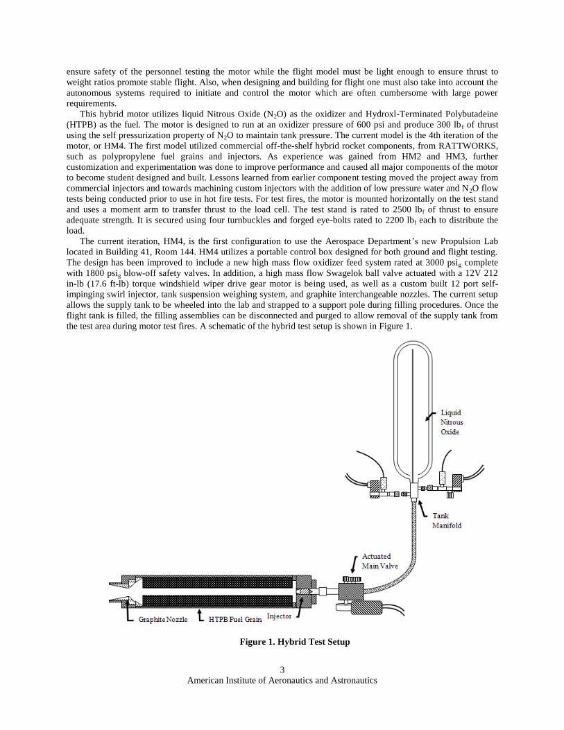
impinging swirl injector, tank suspension weighing system, and graphite interchangeable nozzles. The current setup
allows the supply tank to be wheeled into the lab and strapped to a support pole during filling procedures. Once the
flight tank is filled, the filling assemblies can be disconnected and purged to allow removal of the supply tank from
the test area during motor test fires. A schematic of the hybrid test setup is shown in Figure 1.
Figure 1. Hybrid Test Setup

American Institute of Aeronautics and Astronautics
4
II. Motor Design
A. Oxidizer System
The oxidizer feed system consists of 4 main components. The flight tank is a commercially sourced Kevlar
wrapped Aluminum tank rated for gaseous oxygen. The tank manifold connects the tank to the fill, vent and motor
feed assemblies in addition to safety and sensor systems. A steel braided flexible line delivers oxidizer to the main
valve which controls flow rate into the injector.
1. Tank Manifold
The tank manifold design serves three purposes: to deliver oxidizer from the flight tank to the main valve, to
provide the means of filling the flight tank from the supply tank, and to release pressure in the system in case of an
oxidizer over pressurization. The tank manifold must also withstand the high pressure oxidizer ranges from 600 psig
to 800 psig. The main purpose of the tank manifold is to deliver oxidizer from the flight tank to the main valve; to
accomplish this the flow path between the tank and the main valve needs to remain unrestricted to ensure that the
cryogenic liquid oxidizer remains a liquid until it reaches the injector. Area change and connections within the flow
path must be minimized to reduce the opportunity for tripped flow. To satisfy these requirements, a crescent shaped
opening in the tank manifold is used. This crescent shaped opening maximizes the area at the tank end and also
allows for a smaller secondary hole containing a siphon tube allowing air and gaseous nitrous oxide to escape
through a vent during the filing process. The tank orifice is 0.73 inches in diameter and the main valve has an inner
diameter of 0.5 inches. The crescent shaped hole used on the tank side of the manifold fits inside the 0.73 inch
diameter tank opening and then opens up to a 0.5 inch inner diameter to match the valve orifice. The transition
between the crescent opening and the 0.5 inch diameter opening occurs within the tank manifold where the area
change between them is minimized to a 20% difference. This minimal area change ensures that the cryogenic
oxidizer does not expand rapidly inside the piping causing a phase change from its liquid state to its gaseous state.
Also by manufacturing the tank manifold as one piece the tank manifold is used as the only link between the flight
tank and the main valve; this direct connection reduces the weight of the motor and also reduces the number of
connections in the piping ensuring that there are few trip points to keep the flow of oxidizer smooth.
The tank manifold also provides the means of filling the flight tank with oxidizer from an external supply tank.
To accomplish this task the tank manifold needs two additional flow paths. The first flow path provides a connection
to the flight tank from an external supply tank; this connection merges directly with the flow path from the flight
tank to the main valve. The second flow path merges with the siphon tube located at the tank end of the manifold;
this flow path allows air and gaseous oxidizer to escape from the tank allowing liquid oxidizer to fill into the flight
tank. A 3000 psi self closing quick disconnect valve is used to close these external connections .
The third purpose of the tank manifold is to release excess pressure in the system in the event that the liquid
oxidizer gets too hot and over pressurizes the system. For this a smaller flow path is used that merges with the main
flow path connecting the tank and the main valve. This connection is threaded and a burst cap rated to burst at 1800
psi is used as the pressure relief system. If the system exceeds 1800 psi the burst cap will rupture and release the
contents of the flight tank and feed system to atmosphere.
The tank manifold is manufactured from a single piece of 1.5 inch in diameter hexagonal brass bar stock. The
first step in manufacturing is to cut the stock and face both sides of the brass bar in a lathe to approximately 2.8
inches in length. The tank end of the tank manifold is then turned down to 0.75 inches in diameter where a 3/4 – 16
die is used to cut threads. While turning, the initial rounding operation must be done with care and at a low feed rate
to prevent chattering and vibrations which will eliminate any accuracy in the machine. On the main valve end of the
tank manifold the diameter is turned to 0.84 inches in diameter and a 1/2 – 18 NPT die is used to create the threads.
To create the crescent shaped hole on the tank end of the manifold, the piece is placed into a computer numerically
controlled (CNC) mill where a straight 1/4 inch end mill tool is used to remove the material. The straight 1/4 inch
end mill is needed because the flutes of the tool are the same diameter as the held end of the tool; this allows the end
mill to penetrate into the brass further than a standard end mill. The crescent shape hole is then milled 1.5 inches
deep from the tank end of the manifold. At the main valve end of the tank manifold a 0.5 inch diameter drill is used
and will merge with the crescent shaped hole from the other side of the manifold. Also, at the tank end of the
manifold a smaller hole is drilled using a #24 drill where the siphon tube is inserted; this hole is drilled to a depth of
1.25 inches. On the same side as the dip tube but perpendicular to the hole, another hole is drilled using a 7/16 inch
diameter bit and finished with a flat end mill of the same diameter. This hole is drilled only until the siphone tube
hole is visible. Another 7/16 inch in diameter hole is also drilled on the opposite side of the tank manifold which is

American Institute of Aeronautics and Astronautics
5
perpendicular to the crescent shaped hole that was made earlier. This hole is drilled until it merges with the main
flow path between the tank end of the manifold and the main valve end of the manifold. Both 7/16 holes are then
tapped using a 1/4 NPT bottoming tap. The last hole is used for the burst cap; this hole is a 3/16 hole with and
tapped with a 3/16 – 24 tap. Since the burst disk requires a seat the hole must not be drilled as a through hole; a
through hole into to the flow path must be of a smaller diameter. The burst disk is then screwed into this hole. Figure
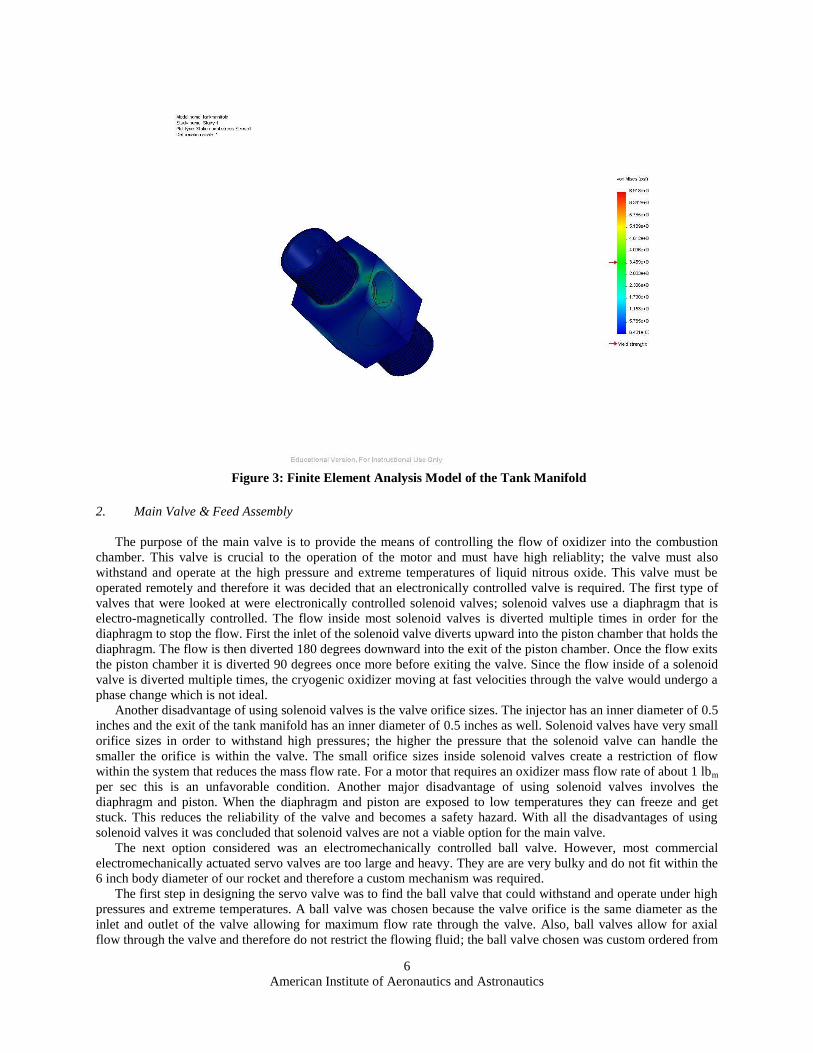
2 shows the construction diagram of the tank manifold. To ensure that the tank manifold is able to withstand the
pressures of the liquid oxidizer a finite element analysis model was created to show the major stress points of the
manifold under pressure. Figure 3 shows the finite element analysis (FEA) model of the tank manifold and
illustrates that the tank manifold can withstand a pressure above 3000 psig.The FEA model is tested using
CosmosWorks embedded into SolidWorks5. Material properties are taken from Military Handbook #5.
5 (Dassualt Systemes SolidWorks Corporation n.d.)
Figure 2: Construction Diagram of Tank Manifold
American Institute of Aeronautics and Astronautics
6
2. Main Valve & Feed Assembly
The purpose of the main valve is to provide the means of controlling the flow of oxidizer into the combustion
chamber. This valve is crucial to the operation of the motor and must have high reliablity; the valve must also
withstand and operate at the high pressure and extreme temperatures of liquid nitrous oxide. This valve must be
operated remotely and therefore it was decided that an electronically controlled valve is required. The first type of
valves that were looked at were electronically controlled solenoid valves; solenoid valves use a diaphragm that is
electro-magnetically controlled. The flow inside most solenoid valves is diverted multiple times in order for the
diaphragm to stop the flow. First the inlet of the solenoid valve diverts upward into the piston chamber that holds the
diaphragm. The flow is then diverted 180 degrees downward into the exit of the piston chamber. Once the flow exits
the piston chamber it is diverted 90 degrees once more before exiting the valve. Since the flow inside of a solenoid
valve is diverted multiple times, the cryogenic oxidizer moving at fast velocities through the valve would undergo a
phase change which is not ideal.
Another disadvantage of using solenoid valves is the valve orifice sizes. The injector has an inner diameter of 0.5
inches and the exit of the tank manifold has an inner diameter of 0.5 inches as well. Solenoid valves have very small
orifice sizes in order to withstand high pressures; the higher the pressure that the solenoid valve can handle the
smaller the orifice is within the valve. The small orifice sizes inside solenoid valves create a restriction of flow
within the system that reduces the mass flow rate. For a motor that requires an oxidizer mass flow rate of about 1 lbm
per sec this is an unfavorable condition. Another major disadvantage of using solenoid valves involves the
diaphragm and piston. When the diaphragm and piston are exposed to low temperatures they can freeze and get
stuck. This reduces the reliability of the valve and becomes a safety hazard. With all the disadvantages of using
solenoid valves it was concluded that solenoid valves are not a viable option for the main valve.
The next option considered was an electromechanically controlled ball valve. However, most commercial
electromechanically actuated servo valves are too large and heavy. They are are very bulky and do not fit within the
6 inch body diameter of our rocket and therefore a custom mechanism was required.
The first step in designing the servo valve was to find the ball valve that could withstand and operate under high
pressures and extreme temperatures. A ball valve was chosen because the valve orifice is the same diameter as the
inlet and outlet of the valve allowing for maximum flow rate through the valve. Also, ball valves allow for axial
flow through the valve and therefore do not restrict the flowing fluid; the ball valve chosen was custom ordered from
Figure 3: Finite Element Analysis Model of the Tank Manifold

American Institute of Aeronautics and Astronautics
7
Swagelok. A stainless steel valve was chosen to withstand the high pressures of the oxidizer and prevent corrosion.
The valve seats were constructed of PEEK or PTFE to ensure that the oxidizer does not erode the seating surface.
The valve stem was designed with compression spring washers, called a live loaded packing system, allowing
automatic self-adjustment when exposed to extreme temperatures. The valve chosen with all of the criteria listed
above is the Swagelok SS-45TF8 shown in Figure 4.
The next step was to find a mechanical actuator to open and close the valve. Since the valve is live loaded the
amount of torque required to actuate it ranges from 8 foot pounds to 9.5 foot pounds of torque depending if the valve
is under pressure or not. The best means of opening the valve, without relying on pyrotechnics, is a motor. The
motor would have to provide the torque required to open and close the valve while it is under pressure and must be
able to open and close the valve within one second. To provide the torque to actuate the valve two gear systems
were used to increase the amount of torque at the valve stem. The first gear reduction occurs at the motor; the motor
utilizes a worm gear and pinion to reduce the speed of the motor and increase the torque. The output shaft of the
motor then turns another pinion gear which is then attached to the spur gear at a 3:1 reduction ratio. This reduction
ratio increases the torque of the motor and reduces the speed of the motor by a multiple of 3. By using these gears
the motor is able to output 16 foot pounds of torque to the valve stem and open and close the valve within 0.45
seconds. The gears were bought from McMaster – Carr and the motor used is an AME 218 series 12 volt long shaft
gear motor shown in Figure 5.
Figure 5: AME 218 series 12 volt long shaft gear motor used to
actuate the ball valve
Figure 4: Swagelok SS-45TF8 stainless steel live loaded ball valve

American Institute of Aeronautics and Astronautics
8
The last step in the design of the main valve assembly was to house the entire assembly together into one piece.
A rigid mounting plate is required to withstand the torques exerted by the motor. Also, the configuration of the
gears, the valve, the motor, and the limit switches had to be held together under very tight clearances in order for the
valve to function properly; to accomplish this task a base plate was constructed that would hold the valve and the
motor securely in place. To ensure the base plate and the top plates are within tolerance both pieces were CNC
machined. The valve is secured into the base plate using two U-bolts, and the motor is held onto the base plate with
screws mounted on the motor‟s gear head assembly. With the motor and valve secured in place,,a top plate is used to
guide the shaft of the motor to prevent the gears from slipping and to hold the limit switches that tell the motor to
stop when the valve is in the fully open or fully closed position. The pinion gear is set onto the motor shaft using a
set screw and the spur gear mounted on the valve is set using a notch and key; the top and bottom plates are then
held together using screws. Figure 6 shows a front and top view of the complete valve assembly. The motor is
placed such that that the U-bolts holding the valve are easily accessible and the motor body is parallel to the flow
path of the valve. By making the body of the motor parallel with the flow path of the valve the whole assembly can
be fit inside of a 6 inch diameter rocket; in particular, „Caution: Flammable‟, a rocket built and test flown by Cal
Poly Space Systems. Figure 7 shows a construction diagram of the base mounting plate as well as the top plate.
When machining the mounting plate be sure to check that the tools fit the part. For example, when
countersinking the screw clearance holes for motor attachment it is necessary to have a tool and chuck combination
which can get into the grooves of the base plate without hitting the walls; you may find that this operation is best
done on a drill press. In order to maintain tool clearance with the part while cutting the deep grooves you may opt to
only grip a minimum of 0.06 inches. This is enough grip-surface as long as feed rates are held low. Use caution and
take your time as these parts require quite a bit of material removal.
A stainless steel braided hose connects the tank manifold to the inlet of the main valve. This PTFE stainless steel
braided hose has an inner diameter of 0.5 inches and has a 1/2 inch NPT male connection at each end. The hose is
needed to bridge the gap between the vertical flight tank and the horizontal chamber. The length was chosen to
match the test configuration; any looping or slack in the line could lead to kinking or other adverse flow effects. The
hose is rated to 1500 psi with a burst factor of 3.
Figure 6: Top and front view of the completed main valve assembly

American Institute of Aeronautics and Astronautics
9
3. Injection Manifold
The injection manifold serves three purposes. Its first purpose is to atomize the liquid oxidizer into small
droplets. Its second purpose is to deliver oxidizer into the combustion chamber at the predicted required mass flow
rate of between 0.8 and 1 lbm/sec. The last task of the injector manifold is to swirl the oxidizer inside of the
combustion chamber to promote mixing with the fuel.
Figure 7: Construction diagrams of both the base plate and the top plate of the main valve assembly

American Institute of Aeronautics and Astronautics
10
A series of experiments were conducted with water to visually observe the flow properties of different injector
configurations and to test their atomization properties. The first experiment conducted was to test the atomization
properties of having a secondary flow impinge on a primary flow. In order to conduct this experiment an injector
was crafted from a piece of wood that contained two separate flow paths. Figure 8 shows a model of the simple
injector used for the experiment; each flow path contained a valve so the effects of each flow could be seen
independently.
The first step of the experiment was to turn on the primary flow through the injector and analyze the flow pattern
and the atomization characteristics. With the primary flow turned on, the flow pattern shows a single stream of
liquid flowing out of the injector as seen in Figure 9. This single stream of fluid shows very little atomization of the
fluid as expected.
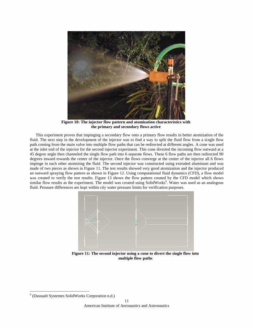
When the secondary flow valve is opened, the secondary flow impinges against the primary flow and atomizes
the liquid. This atomization is seen in Figure 10 where there aren‟t any visible solid streams of fluid exiting the
injector. Also, the flow pattern with both the primary and secondary flows active shows a more conical shaped spray
pattern.
Figure 9: The injector flow pattern and atomization characteristics with
only the primary flow active
Figure 8: The injector design for the primary and secondary flow atomization
experiment
American Institute of Aeronautics and Astronautics
11
This experiment proves that impinging a secondary flow onto a primary flow results in better atomization of the
fluid. The next step in the development of the injector was to find a way to split the fluid flow from a single flow
path coming from the main valve into multiple flow paths that can be redirected at different angles. A cone was used
at the inlet end of the injector for the second injector experiment. This cone diverted the incoming flow outward at a
45 degree angle then channeled the single flow path into 6 separate flows. These 6 flow paths are then redirected 90
degrees inward towards the center of the injector. Once the flows converge at the center of the injector all 6 flows
impinge in each other atomizing the fluid. The second injector was constructed using extruded aluminum and was
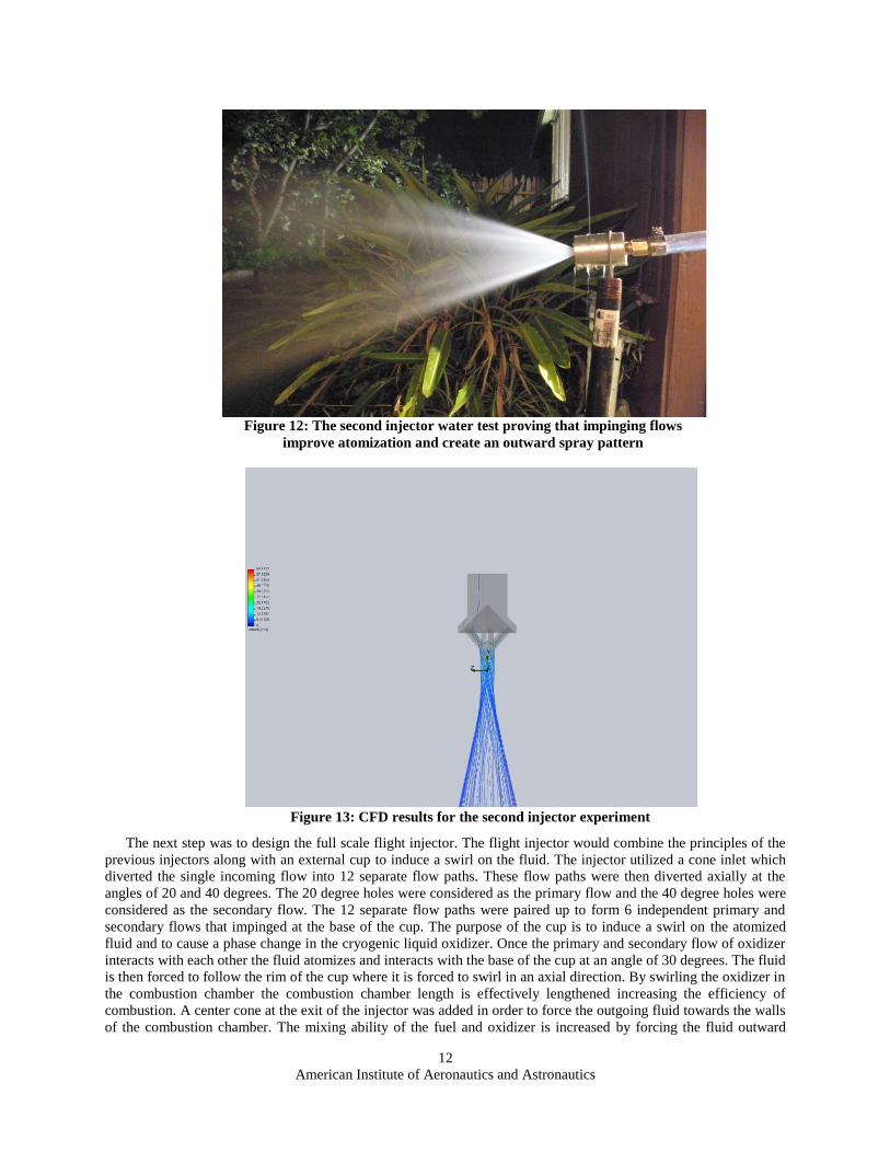
made of two pieces as shown in Figure 11. The test results showed very good atomization and the injector produced
an outward spraying flow pattern as shown in Figure 12. Using computational fluid dynamics (CFD), a flow model
was created to verify the test results. Figure 13 shows the flow pattern created by the CFD model which shows
similar flow results as the experiment. The model was created using SolidWorks6. Water was used as an analogous
fluid. Pressure differences are kept within city water pressure limits for verification purposes.
6 (Dassualt Systemes SolidWorks Corporation n.d.)
Figure 11: The second injector using a cone to divert the single flow into
multiple flow paths
Figure 10: The injector flow pattern and atomization characteristics with
the primary and secondary flows active
American Institute of Aeronautics and Astronautics
12
The next step was to design the full scale flight injector. The flight injector would combine the principles of the
previous injectors along with an external cup to induce a swirl on the fluid. The injector utilized a cone inlet which
diverted the single incoming flow into 12 separate flow paths. These flow paths were then diverted axially at the
angles of 20 and 40 degrees. The 20 degree holes were considered as the primary flow and the 40 degree holes were
considered as the secondary flow. The 12 separate flow paths were paired up to form 6 independent primary and
secondary flows that impinged at the base of the cup. The purpose of the cup is to induce a swirl on the atomized
fluid and to cause a phase change in the cryogenic liquid oxidizer. Once the primary and secondary flow of oxidizer
interacts with each other the fluid atomizes and interacts with the base of the cup at an angle of 30 degrees. The fluid
is then forced to follow the rim of the cup where it is forced to swirl in an axial direction. By swirling the oxidizer in
the combustion chamber the combustion chamber length is effectively lengthened increasing the efficiency of
combustion. A center cone at the exit of the injector was added in order to force the outgoing fluid towards the walls
of the combustion chamber. The mixing ability of the fuel and oxidizer is increased by forcing the fluid outward
Figure 13: CFD results for the second injector experiment
Figure 12: The second injector water test proving that impinging flows
improve atomization and create an outward spray pattern

American Institute of Aeronautics and Astronautics
13
towards the fuel grain. Before the actual injector was manufactured, a CFD model was created to analyze the flow
pattern. Figure 14 shows the results of the CFD model which provided the desired flow pattern of the fluid exiting
the injector. The CFD model, Figure 14, shows a low pressure region created by the impinging flow at the base of
the cup; this low pressure region aids in the phase change of the oxidizer from a liquid to a gas which is ideal.
The injector was constructed using 3 pieces of extruded 6061 aluminum. The inlet piece of the injector connects
to the main valve and is screwed into the outlet piece of the injector by 5 screws in a bolt circle. A PTFE O-Ring is
used to seal the two pieces together and prevent leaks. The inlet side of the injector has 1/2 inch NPT male threads
at one end and the exterior cone section of the injector. The outlet piece of the injector has the inner cone section
that diverts the flow of fluid outward as well as the 12 ports that expel the fluid into the cup and into the combustion
chamber. The screws are tightened in a star pattern. The third piece of the injector is the center cone at the outlet
side of the injector which helps guide the fluid outward towards the fuel grain; this center cone is held in place by a
screw. During hot fire tests this center cone melted away; further experimentation requires the use of graphite or
more exotic metals with high melting temperatures. Figure 15 shows the construction diagram of the outlet injector
piece.
The inlet piece of the injector and the center cone are easily constructed by even a novice machinist, however the
main body of the injector is the most difficult. This piece was designed with a specific process in mind. The main
stock is CNC lathed and milled, as shown in Figure 16, to form a boss which includes most features except the cone;
Figure 14: The CFD test results of the flight injector where the top shows the flow pattern of one pair of
injection ports and the bottom shows the pressure inside of the injector

American Institute of Aeronautics and Astronautics
14
the piece is a 2 inch extrusion at this point, the angled injector holes and threads (codes number 440 and 441 on the
Haas VF2 in Mustang ‟60 for a stock length of 1.7 inches). The next step is to chuck the piece on the to-be cone
extrusion and add the threads which will connect to the casing. Next flip the part over and chuck on the 0.25 inch
recession, added for this specific purpose, and turn the center cone. It is suggested to use a boring bar and spinning
the part in reverse, as shown in Figure 18; this is a point of no return. If any repairs must be done on the threads a
new part is recommended. The next steps are done on a mill with a rotary table attachment. The mill head needs to
be angled therefore the manual knee mill is recommended such as the Bridgeport or Ganesh in the ME Special
Projects Lab. Due to clearance issues use the method noted in the Appendix.
Figure 15. Construction Drawing of Injector

American Institute of Aeronautics and Astronautics
15
Figure 17. Method for Drilling Angled Holes in Aero Hangar Machine Shop
Figure 16. Injector Blank in process on HAAS VF2 Mill at Mustang '60 Machine Shop

American Institute of Aeronautics and Astronautics
16
B. Combustion Chamber
The combustion chamber, motor casing, is a vital part in the safety and performance of the hybrid rocket
motor. Unlike solid or liquid rocket engines the thermal gradient along the length of the chamber can vary
greatly; this fact is perceivable immediately following a test fire. The injector side of the motor is only warm to
the touch but the nozzle side of the chamber is capable of flash boiling drops of water. Nevertheless, the chamber
must be capable of withstanding 3000 psia of static pressure with a burst factor of 3 at qualification level loads.
At the same time it must follow the Tripoli Rocketry Safety codes7 outlining specific material requirements and
it must fit in standard 98 mm amateur rocket style motor mounts.
Based on the requirements above, the casing is made of 6061-T6 aluminum shown in Figure 19. End caps are
held on by threads which maintain constant load paths rather than dual radial bolt circles more readily seen in
large amateur solid rocket motor development; these develop stress points at the screw locations shown in Figure
20. The lack of stress concentrations allows for analysis to remain primarily analytical rather than requiring
advanced methods such as FEA. This also allows the casing to remain thinner to reduce weight. Aluminum
6061-T6 has a yield tensile stress of 40 ksi8. Equation 1 (Beer, Johnston and DeWolf 2006) allows us to
determine the casing thickness based on hoop stress for a thin wall cylinder.
(1)
The minimum thickness for the casing is 0.3940 inches; this thickness applies in particular to the thread
portions of the casing since they are the thinnest. However within our thickness constraints of 0.25 inches a
maximum burst factor of only 1.90 can be achieved, based on this burst factor the minimum thickness must be
7 (Tripoli Rocketry Association n.d.)
8 (American Society of Metals 1990)
Figure 18. Machining Setup for Flow Control Cone on Injection Manifold
(Note: Part spun in reverse and chucked from the inside out)
American Institute of Aeronautics and Astronautics
17
larger than 0.131 inches. In order for a burst factor of 3 to be retained the internal pressure must be held under
1900 psig. The burst cap safety valve triggers at 1800 psig, allowing a 5.6 % margin.
This lower burst factor can result in large deflections in the casing radius when fully pressurized allowing
some blow-by of the seals. No blow-by has been experienced in the past and the seals followed precedent;
however the higher pressures experienced in testing showed that a new sealing method must be developed. The
standard sealing method consists of o-rings tightened to compress against the fuel.
The casing of HM3 was chosen for the first test fires since it had already been proven to hold combustion
pressure during previous test fires. Unfortunately due to an error in manufacturing it had a right-handed thread on
one side and a left-handed thread on the other; in addition both threads had different minor and major diameters.
Although the different thread directions were a pure mistake on the part of the former student who built it, the
reason for the different diameters is unknown. Both threads are cut at 18TPI; this pitch gives the required grip
area and shear allowance to withstand combustion pressure.
Due to failure of the HM3 during the first test fire, a new casing was manufactured; the new casing is built
shorter to fit three 4.5 inch long grains. Since the end caps were already threaded when the new casing was made
it was decided to keep the awkward threads even though a complete rebuild of the motor would have been
beneficial. A decision to rebuild all of the components would have put the project severely behind schedule and
testing would be further delayed.
Care was taken during the manufacturing process; a steady rest and a well centered lathe chuck shown in
Figure 21 were used. The part was not turned faster than 100 rpm when using the steady rest to avoid the
harmonics of the tube. Internal threads were cut using a boring bar ground to the required 30 degree cut angle.
Each cut was verified twice to ensure precise machining; particular care was taken on the threads because
interfaces between parts can cause damage and fit issues to multiple parts.
Figure 19: Casing Construction Drawing

American Institute of Aeronautics and Astronautics
18
C. Nozzle
The nozzle is designed for three criteria: easy reconfiguration for a variety of tests, flight readiness, and low cost.
Material for the nozzle, the throat in particular, was the most difficult to determine. The nozzle had to withstand
temperatures estimated past 3000 degrees Rankine and flow velocities above Mach 3. These two requirements
influenced materials choices towards metals such as Inconel. Unfortunately no steel can be used in the construction
of an amateur rocket motor as per the Tripoli Rocketry Association Safety code9; chromium-molybdenum based
steel and graphite have been used in the past for ground testing. Industry contacts suggested silica impregnated cast
9 (Tripoli Rocketry Association 2010)
Figure 21: Casing Blank Mounted on Lathe
Figure 20: Radial Bolt Style End Cap Retention (Nakka n.d.)

American Institute of Aeronautics and Astronautics
19
phenolic nozzles from a commercial supplier; while these seemed like a trivial solution they turned out to be rather
expensive and had a low variety of geometries and throat diameters for our size of rocket motor.
The decision was made to use graphite as the nozzle material. While erosion is an issue with graphite, the ease of
manufacturing, the thermal properties, and the readily available stock material favored the decision. A two piece
nozzle design meant that a minimal amount of graphite dust is created in manufacturing and stock material costs are
reduced. Sealing the two graphite pieces together posed a difficult problem at first since precedent warranted the use
of lithium grease as the primary gap sealer. A labyrinth seal and press-fit components were the solution that
provided the simplest manufacturing and simple integration of components. An industry contact recommended the
use of RTV adhesive silicone sealant; at first this recommendation seemed eccentric since RTV silicone is
flammable and has a melting temperature less than 1000 degrees Fahrenheit. Despite these facts the sealant was used
and the labyrinth seal was removed. The results in the second test fire revealed that the sealant is remarkable in its
ability to adhere and seal gaps even when exposed to temperatures in excess of 4000 degrees Rankine and Mach 0.8
gas flows. White lithium grease is used elsewhere to facilitate assembly, disassembly, and prevent residue build up
in places such as the threads. Automotive gasket material is planned for future sealant material following the same
technique of compression against the fuel grain. The material is expected to reduce burning which occurs at the top
and bottom of the grain as well as providing a larger seal radial thickness reducing gas penetration and preventing
gas-to-casing contact.
An initial throat diameter of 0.75 inches was chosen based on data from previous analysis on HM3 and steady
state analysis using isentropic flow equations from Sutton10
. The expansion ratio of 5.2 was determined through the
same isentropic steady state equations for an average chamber pressure of 450 psia. This combination is designed to
produce near optimum sea level thrust at that steady state condition; for HM4 this should be about midway through
the burn. Radii of curvature for rounded or parabolic faces are derived as a function of throat radius using empirical
data from Huzel11
.
Codes on the HAAS VF2 machine, # 518 and # 519, in the Mustang ‟60 shop were used to remove a majority of
the material from a 4 inch extruded rod, 2.5 inch long billet. At this point the piece only required cleaning and
threads. In addition the VF2 machine with the rotary table installed can break tools during a tool change since the
machine will bring the tool holders down to the rotary table height. Use of the „G54 G00 X-12‟ code before each
tool change, or „T‟ command‟, was used in order to move the table out of the way. The part was made with a 3 flute,
0.25 inch diameter carbide flat end mill running at 10000 rpm; a feed rate of 25 to 50 inches per minute (XY axis)
and 0.05 to 0.1 depth of cut was used with plenty of coolant. The recess cut on the chamber side was used to grip the
nozzle in a chuck once the threads were cut to avoid gripping the threads themselves. Due to the relative fineness of
the threads care must be taken when machining them. Depths of cuts were limited to 0.002 to 0.005 inches. These
are the same „speeds and feeds‟ and tools that should be used on the injector CNC operations.
A vacuum cleaner was used when cutting graphite to suck in debris as it came off the part. This operation
required two people; each person was equipped with safety equipment as demonstrated in Figure 25. Graphite is
also very brittle so care was taken not to over tighten any clamp or jaws. As the part was bored through it grew
weaker so the jaws were loosened accordingly. Graphite can be spun fast and endure a large depth of cut so long as
centrifugal forces are satisfied and the cutting tool is very sharp with a large rake angle. The 4 inch diameter
graphite was never spun faster than 1500 rpm particularly when it was bored out. Special care was taken to ensure a
centered chuck; failure to do so would cause the part to shatter due to vibrations.
10
(Sutton and Biblarz 2001) 11
(Huzel and Huang 1992)

American Institute of Aeronautics and Astronautics
20
Figure 23: Construction Drawing of Graphite Convergence Section
Figure 22: Construction Drawing of Graphite Throat Section (2nd
Test Fire Dimensions)

American Institute of Aeronautics and Astronautics
21
D. Fuel Grains
This hybrid setup utilizes hydroxyl-terminated-polybutadeine, HTPB, as the fuel, a tire rubber and common
binder in solid rocket fuels. Alone it is non-combustible, very stable and safe to handle. There are various blends
available, we use HTPB R45M obtained from Aerocon Systems12
with PAPI 94 as a curing agent. Experiments with
the fuel grains were conducted by using additives such as: castor oil, carbon black, Silicone oil, dioctyl adipate
12
Aerocon Systems, http://www.aeroconsystems.com/
Figure 25: Safety Equipment when Machining Graphite
(Note: Tuck All Hanging Cords into Shirt before Machining)
Figure 24: Nozzle End Cap Construction Drawing

American Institute of Aeronautics and Astronautics
22
(DOA), and dibutyltin dilaurate cure catalyst (DBDTL). The goal of the additives was to reduce bubble formation by
decreasing the viscosity of the mixture so bubbles can escape easier, decrease the brittleness of the fuel grain, and
reduce the glass transition temperature to prevent cracking of the grain. These additives in particular were chosen
based off of recommendations from the Aerocon website, the MaCH-SR1 project reports from the University of
Colorado, Boulder (Alagic, et al. 2006), and John Campbell from SpaceDev (now Sierra Nevada Corporation).
Castor oil and silicone oil are used to reduce the viscosity of the mix and allow easier blending and escape of
bubbles. Dioctyl adipate is used to make the grain softer and more flexible and dibutyltin dilaurate cure catalyst is
used to decrease the curing time for the mixture.
Historical testing had made attempts towards vacuuming, but a successful apparatus was never achieved. Mason
jars with a composite layup vacuum pump were used to remove the air and bubbles from the grain. This method
resulted in lots of bubbles at the top and cured HTPB with solid pieces at the bottom. Due to the bubbles, only the
bottom of the grains could be used. Shaping the grains in the mason jar also posed a problem because the center core
molding piece could not be accurately secured and too much post-molding processing was required. It was
determined that a proper apparatus for vacuuming the grains would be too costly for the current budget as it would
need to hold a strong vacuum on a large amount of fuel while still being able to stir and mix it; experimenting with
additives and mixture ratios proved sufficient so that funds can be utilized on the overall test setup and oxidizer
system.
Initial tests were conducted using previous molds and samples of 50 to 60 grams; the tests are shown in Figure
26. Thirteen molding tests were completed varying mixture ratios and curing techniques to obtain the best fuel
consistency; the various experiments are organized in Table 1. The mixtures from Cure Tests 7 and 8 are
highlighted in green since they produced the most promising and consistent results. These cures were expected to
produce the best performance out of the motor. Cure test 9 is highlighted in red because it cured too rapidly while
being poured and was unusable.
Figure 26. Initial 60 gram fuel grain tests.

American Institute of Aeronautics and Astronautics
23
Heated tests were conducted placing the molds in a metal cabinet with two halogen lamps to provide the heat
during the curing process. The same mixture was used for both hot and cold cure tests, the results are shown in
Figure 27. It was found that heating the grain to temperatures around 130 °F as it cured increased the number of
bubbles as well as their respective size. From these results we determined that cold cures of the HTPB would be
sufficient once the optimal mixture ratio was found.
As aforementioned, cure tests 7 and 8 produced the best results showing a large reduction in bubbles with no
large pockets present. Figure 28 shows cure 7 and Figure 29 shows Cure 8. Cure 7 used 84% HTPB with 12% PAPI
curing agent and 4% castor oil. This produced a very flexible and elastic mold with only tiny bubbles spread evenly
Figure 27. Cold Cure (left), and Hot Cure (right)
Table 1. Fuel Grain Mixture Experiments
HTPB
PAPI
94
Castor
Oil
Carbon
Black DOA
Silicone
Oil DBDTL
Test
Total
Mass
(g)
Ratio Ratio Ratio Ratio Ratio Ratio Ratio
1 63.0 84.13% 9.52% 6.35% 0.00% 0.00% 0.00% 0.00%
2 63.7 83.20% 10.52% 6.28% 0.00% 0.00% 0.00% 0.00%
3 60.5 86.78% 12.23% 0.99% 0.00% 0.00% 0.00% 0.00%
4 61.0 85.08% 12.95% 1.97% 0.00% 0.00% 0.00% 0.00%
5 61.0 85.08% 13.77% 1.15% 0.00% 0.00% 0.00% 0.00%
6 60.8 83.88% 13.16% 2.96% 0.00% 0.00% 0.00% 0.00%
7 60.0 84.00% 12.00% 4.00% 0.00% 0.00% 0.00% 0.00%
8 60.5 83.14% 12.40% 3.97% 0.50% 0.00% 0.00% 0.00%
9 61.0 83.44% 12.13% 3.28% 0.00% 0.82% 0.16% 0.39%
10 60.4 83.28% 12.58% 2.98% 0.00% 1.16% 0.05% 0.05%
11 60.0 83.00% 12.00% 4.00% 0.50% 0.50% 0.05% 0.00%
12 61.0 81.15% 11.97% 3.93% 0.49% 2.46% 0.10% 0.00%
13 200.0 84.00% 12.00% 4.00% 0.00% 0.00% 0.00% 0.00%

American Institute of Aeronautics and Astronautics
24
throughout. Despite any additional additives, no cure resulted with less bubbles. Carbon black was added to this
mixture at a ratio of 0.5% resulting in cure 8. This mold was slightly stiffer than cure 7 due to the carbon addition
and it was estimated that the carbon would improve heat transfer during the combustion process (Chiaverini and
Kuo 2007).
A large scale mold test was conducted as cure 13 with this mixture ratio to verify that scaling the mold size
would not have major affects to the quality of the grain. Figure 30 shows the results of the cure; the consistency and
quantity of bubbles was identical to that seen in the small scale cure.
Figure 29. Fuel Cure 8
Figure 28. Fuel Cure 7

American Institute of Aeronautics and Astronautics
25
1. Fuel Grain Molds
New molds were created to assist in curing the fuel grains for motor test fires. Previously, only one fuel mold
was available for curing, greatly increasing the curing time to obtain an entire grain set for a test fire. The new
molds, Figure 31 and Figure 32, allow for curing three grains simultaneously. They also have a much simpler
compression-fit design, as opposed to a threaded design, increasing simplicity and facilitating removal of the grain
after it has cured. They also contain two PVC pipes in the center of the mold to provide the core geometry for the
grain. The use of two pipes allows for interchangeability of the outer to adjust the core geometry for various shapes
and sizes for experimentation in fuel regression properties.
Figure 31. Fuel Molds
Figure 30. Cure 13: Large Scale Fuel Cure
American Institute of Aeronautics and Astronautics
26
A film of petroleum jelly is applied to the aluminum mold and PVC pipe core. This lubricant assists in the
removal of the grain from the mold after curing. Custom fuel grain liners have also been researched from the
Precision Paper Tube Company13
; using a resin impregnated cardboard (phenolic tube) would be the best option for
aiding in grain removal. Grain liners would also be beneficial for fuel grain compression and heat transfer during
combustion. Use of these liners is the next step in fuel grain manufacturing once an increased budget is established.
The full procedures for curing fuel grains are shown in the appendix.
2. Fuel Curing
Three 525 gram mixes were made to provide a complete set of fuel grains for a test fire. The HTPB, castor oil,
and carbon black are first mixed and allowed to sit for one hour before adding the PAPI curing agent. This hour set
time allows the HTPB to outgas and help reduce the number of bubbles that result. Figure 33 shows the fuel mixes
ready for pouring.
After adding the PAPI curing agent, a mixer attached to a drill was used to ensure a thorough blend throughout
the grain, Figure 34.
13
Precision Paper Tube Company, http://www.pptube.com/
Figure 32. Fuel Mold Dimensions
American Institute of Aeronautics and Astronautics
27
The effort put into the mixing process has a substantial impact on the resulting fuel grain; not enough mixing
will prevent the grain from curing. Figure 35 shows the resulting grains once cured.
III. Testing Facilities
A. Test Stand
The test stand shown in Figure 36 is used for all hot and cold flow tests done on the motor. For the purposes of
this project it was relocated from the hangar test cell to the Aerospace Engineering department propulsion lab
(building 41-144) and repaired. It is rated to take thrust loads up to 2500 lbf and is mounted to the floor via 4 forged
eye bolts connected to turnbuckles mounted to ½” bolts into the cement floor. Breakaway boards and wiring were
hooked up for valve control and sensors using the existing wiring in the lab, Figure 37 and Figure 38.
Figure 35. Cured Fuel Grains
Figure 34. Fuel Mixer
Figure 33. Fuel Mix with Carbon Black
American Institute of Aeronautics and Astronautics
28
B. Control Box
A portable control box was also constructed to operate all of the valves and ignite the motor remotely. It operates
off a rechargeable 12 volt lead acid battery to provide for lab and field use when the oxidizer tank is filled on the
field prior to liftoff. Battery operated control of the valves also allows for the system to be depressurized in the event
of a power failure. The box contains two arming circuits, one for filling and one for firing the motor. A buzzer
activates when the firing system is armed thereby warning all personnel involved of danger. The box is shown in
Figure 39 and a circuit diagram in Figure 41. Opening the solenoid valves requires continuous current, but the fire
valve only requires a trigger signal. This is due to the separate control circuit for the valve actuator; a modified H-
bridge allows remote control of the valve circuit using a separate power source; sending high currents through the
building‟s sensor wiring is not advisable. The valve control circuit is shown in Figure 40.
Figure 39. Portable Control Box
Figure 38. Lab Connections
Figure 37. Test Stand Wiring
Figure 36. Hybrid Test Stand

American Institute of Aeronautics and Astronautics
29
Figure 41: Control Box Circuit Diagram
Figure 40. Modified H-Bridge Valve Control Circuit
American Institute of Aeronautics and Astronautics
30
C. Sensors and LabVIEW Data Acquisition
Two pressure transducers with a 1 to 1000 psig range and two load cells are utilized to obtain nitrous oxide
pressure, tank weight, and motor thrust. The pressure transducers, Omega model PX302-1KGV, are located on both
the fill and vent assemblies; this provides both liquid pressure and gaseous pressure of the nitrous oxide during the
filing process. Once the oxidizer tank is filled the fill side is removed and only gas pressure is obtained during the
fire. The oxidizer tank hangs from one load cell, an Omega model LCFD-50 with a 1 to 50 lbf range, to obtain
nitrous mass during filling and firing. The other load cell, an Omega LC101-500 with a 1 to 500 lbf range, is
mounted to the top of the stand and measures thrust using a moment arm. The moment arm has an adjustable
fulcrum to account for various thrust predictions and ensure accurate data without damaging the sensor. All of the
sensor data is routed through a National Instruments USB-6008 DAQ and into LabVIEW. Data is displayed and
recorded to a Microsoft Excel spreadsheet for processing. Test data shows that an external low band pass filter may
be beneficial and is recommended for future testing.
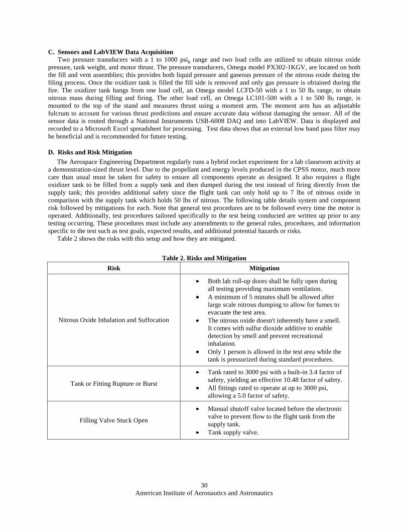
D. Risks and Risk Mitigation
The Aerospace Engineering Department regularly runs a hybrid rocket experiment for a lab classroom activity at
a demonstration-sized thrust level. Due to the propellant and energy levels produced in the CPSS motor, much more
care than usual must be taken for safety to ensure all components operate as designed. It also requires a flight
oxidizer tank to be filled from a supply tank and then dumped during the test instead of firing directly from the
supply tank; this provides additional safety since the flight tank can only hold up to 7 lbs of nitrous oxide in
comparison with the supply tank which holds 50 lbs of nitrous. The following table details system and component
risk followed by mitigations for each. Note that general test procedures are to be followed every time the motor is
operated. Additionally, test procedures tailored specifically to the test being conducted are written up prior to any
testing occurring. These procedures must include any amendments to the general rules, procedures, and information
specific to the test such as test goals, expected results, and additional potential hazards or risks.
Table 2 shows the risks with this setup and how they are mitigated.
Table 2. Risks and Mitigation
Risk Mitigation
Nitrous Oxide Inhalation and Suffocation
Both lab roll-up doors shall be fully open during
all testing providing maximum ventilation.
A minimum of 5 minutes shall be allowed after
large scale nitrous dumping to allow for fumes to
evacuate the test area.
The nitrous oxide doesn't inherently have a smell.
It comes with sulfur dioxide additive to enable
detection by smell and prevent recreational
inhalation.
Only 1 person is allowed in the test area while the
tank is pressurized during standard procedures.
Tank or Fitting Rupture or Burst
Tank rated to 3000 psi with a built-in 3.4 factor of
safety, yielding an effective 10.48 factor of safety.
All fittings rated to operate at up to 3000 psi,
allowing a 5.0 factor of safety.
Filling Valve Stuck Open
Manual shutoff valve located before the electronic
valve to prevent flow to the flight tank from the
supply tank.
Tank supply valve.

American Institute of Aeronautics and Astronautics
31
Venting Valve Stuck Open
Adjustable needle valve located between the tank
and the electronic valve can be used to prevent
continuous escape of flow.
Relatively small amount of nitrous storage
capability of 7 pounds in the flight tank, so the
main valve can be used to purge the entire system.
Power Outage All control circuits and valves run off of batteries,
enabling operation in the event of a power outage.
Spontaneous Combustion of Nitrous Oxide
Non-combustible gas requires dissociation before
ignition can occur.
Can decompose at temperatures as low as 550K
which is not achievable in the oxidizer system.
Nitrous Oxide can react with bearing, valve seats,
and seals made from Teflon and krytox; it can also
react with PTFE but only at 630K. These materials
have been eliminated from the system or used
minimally.
Spontaneous Combustion of HTPB
HTPB is a very stable and inert rubber commonly
found in tires, it has a flash point of > 400 °F in an
open container and isn‟t capable of spontaneous
combustion.
Tank Over Pressurization
Two pressure transducers located on the tank
assembly monitoring both gas and liquid pressures.
Addition of 1800 psi burst discs on the tank
manifold ensure 3000 psi component ratings are
never reached.
Combustion Chamber Over Pressurization
Combustion chamber design to 1900 psi, enabling
1.9 factor of safety.
Increased combustion chamber pressure above
oxidizer tank pressure will increase backpressure
on the injector preventing flow to continue
effectively choking off the oxidizer and stopping
combustion.
Generation of Higher than anticipated Thrust Test stand rated to 2500 lbf of thrust with an
expected thrust of 300 lbf allowing an 8.3 factor of
safety.
IV. Non-Steady State Analysis
A. The System and Interrelations
In order to simplify calculations the following overall assumptions were made:
1) Isentropic flow of an ideal gas
2) Adiabatic compression and expansion of gasses
3) Oxidizer and exhaust are perfect gasses
4) Burn temperature is constant enough to assume constant
5) Combustion stops when either fuel or oxidizer run out
6) Oxidizer is self pressurized
7) Single cylindrical core burn grain geometry
8) Gas in chamber can be considered as in a stagnant state

American Institute of Aeronautics and Astronautics
32
B. Intentions
The intention of this analysis was to obtain thrust curves and approximate total impulses for a NOS/HTPB
hybrid rocket motor. The analysis was conducted to apply modularity such that the same concepts expressed here
could be used for other rocket projects. As a note of warning, the equations presented here are correct in concept;
however a unit check is required before implementation.
1. The Nozzle
Since force and impulse are the required solutions, analysis starts at the nozzle. Force is described as a
combination of a jet and hydraulic force shown in Eq. 2 (Sutton and Biblarz 2001). Impulse is the time integral of
this force, Eq. 3. Finally specific impulse describes efficiency, Eq. 4.
(2)
(3)
(4)
Since a simple DeLaval converging-diverging nozzle is assumed, the isentropic flow equations can be used.
However, a check must be done to ensure choked flow; this is done by finding the Mach number at the entrance to
the converging section. Starting with Eq. 5 and the mass flow rate described by Eq. 6, Eq. 7 is used to determine the
Mach number.
(5)
(6)
(7)
A1 is the geometric intake area of the convergent section of the nozzle if and only if there is significant spacing
between the nozzle convergence and the end of the grain port. If this is not true, you must assume that the intake
area of the nozzle is the exit plane area of the grain port. The theoretical compression area ratio required to choke
the flow is obtained from Eq. 8 (Zucrow and Hoffmann 1976).
(8)
Comparing this to the actual compression ratio we find that if εtheo is greater than ε1 then the nozzle is not
choked and therefore it can be considered a smooth orifice where the mass flow rate is defined by Eq. 9 (Huzel and
Huang 1992), the exit velocity is defined by Eq. 10, and the exit pressure is defined by Eq. 11.
(9)
(10)
(11)
American Institute of Aeronautics and Astronautics
33
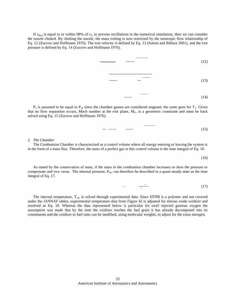
If εtheo is equal to or within 98% of ε1, to prevent oscillations in the numerical simulation, then we can consider
the nozzle choked. By choking the nozzle, the mass exiting is now restricted by the isentropic flow relationship of
Eq. 12 (Zucrow and Hoffmann 1976). The exit velocity is defined by Eq. 13 (Sutton and Biblarz 2001), and the exit
pressure is defined by Eq. 14 (Zucrow and Hoffmann 1976).
(12)
(13)
(14)
P1 is assumed to be equal to Pch since the chamber gasses are considered stagnant; the same goes for T1. Given
that no flow separation occurs, Mach number at the exit plane, ME, is a geometric constraint and must be back
solved using Eq. 15 (Zucrow and Hoffmann 1976).
(15)
2. The Chamber
The Combustion Chamber is characterized as a control volume where all energy entering or leaving the system is
in the form of a mass flux. Therefore, the mass of a perfect gas in this control volume is the time integral of Eq. 16.
(16)
As stated by the conservation of mass, if the mass in the combustion chamber increases so does the pressure to
compensate and vice versa. The internal pressure, Pch, can therefore be described in a quasi-steady state as the time
integral of Eq. 17.
(17)
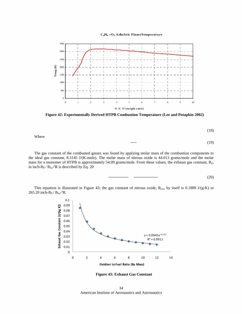
The internal temperature, Tch, is solved through experimental data. Since HTPB is a polymer and not covered
under the JANNAF tables, experimental temperature data from Figure 42 is adjusted for nitrous oxide oxidizer and
resolved as Eq. 18. Whereas the data represented below is particular for swirl injected gaseous oxygen the
assumption was made that by the time the oxidizer reaches the fuel grain it has already decomposed into its
constituents and the oxidizer to fuel ratio can be modified, using molecular weights, to adjust for the extra nitrogen.
American Institute of Aeronautics and Astronautics
34
(18)
Where
(19)
The gas constant of the combusted gasses was found by applying molar mass of the combustion components to
the ideal gas constant, 8.3145 J/(K-mole). The molar mass of nitrous oxide is 44.013 grams/mole and the molar
mass for a monomer of HTPB is approximately 54.09 grams/mole. From these values, the exhaust gas constant, RE,
in inch-lbf / lbm-ºR is described by Eq. 20
(20)
This equation is illustrated in Figure 43; the gas constant of nitrous oxide, ROx, by itself is 0.1889 J/(g-K) or
265.20 inch-lbf / lbm-ºR.
Figure 43: Exhaust Gas Constant
y = 0.0945x-0.737
R² = 0.9911
0
0.01
0.02
0.03
0.04
0.05
0.06
0.07
0.08
0.09
0.1
0 2 4 6 8 10 12 14
Exh
aust
Gas
Co
nst
ant
(J/(
kg K
))
Oxidizer to Fuel Ratio (By Mass)
Figure 42: Experimentally Derived HTPB Combustion Temperature (Lee and Potapkin 2002)

American Institute of Aeronautics and Astronautics
35
The mass of the gas in the chamber is the time integral of Eq. (16). The chamber volume is the sum of the
geometric free space which is described by the grain port. Therefore the initial volume is expressed by Eq. 21.
(21)
This volume, Vch, changes with time as defined by Eq. 22.
(22)
Equation 21 and Equation 22 assume a constant radial regression along the entire length. However, as with many
other hybrid rockets, one can expect to see more regression near the injector orifice and less towards the nozzle end.
There are many models for fuel regression in hybrid rocket motors, yet they are all too specific and not applicable to
our case. It was decided to develop a layman method which can characterize any core burning hybrid rocket grain.
To begin the grain is split into sequential cylindrical grains each dl in length as in Figure 44.
Each section is characterized by the fuel regression equation, Eq. 23 (Sutton and Biblarz 2001), by setting a, n,
and rport as discrete functions of length; only the oxidizer mass flux at the point of injection is considered. In any
case, fuel grain regression is defined by Eq. 23 (Sutton and Biblarz 2001). If a and n are functions of length then it is
defined by Eq. 24. In addition, if al, nl and rport are functions of Length, l, then Eq. 25 applies. The regression
variables must be experimentally derived for each test case.
(23)
(24)
(25)
3. The Injector
The transient solution for the oxidizer mass flow, is fairly easy to solve as a function of the pressure drop
from the oxidizer storage tank and chamber, however all equations require some experimentally derived values. The
experimentally derived values for this injector are outlined in Table 3. It was determined that the head loss
coefficient did change as a function of mass flow from testing, as shown in Figure 45.
Figure 44: Regression Model Dimensions
Oxidizer Mass Flow
Length (L)
l
r
dl rPort

American Institute of Aeronautics and Astronautics
36
The noise in the readings, R
2 = 52%, was deemed too large to apply this phenomenon to the model, however
additional testing may prove this application necessary. From this data, mass flow is estimated by Eq. 26 (Huzel and
Huang 1992).
(26)
This equation applies to any injector as long as the assumption of liquid flow is made. The experimental values
in Table 3 were derived from the system operating in full test configuration. Testing the injector at a pressure drop
comparable to actual flight will result in a more applicable performance prediction.
4. The Oxidizer Tank
The final variable is tank pressure, PT. There are two methods to solve for this variable: the adiabatic model,
which only applies when the oxidizer is pressurized higher than its vapor pressure at operating temperatures from
the beginning to the end of the burn, and the energy method, which applies in our case and any case where the
oxidizer self pressurizes the tank on the vapor boundary.
Adiabatic Model
The adiabatic model works the same way as gas moving a piston. Pressurant applies force to the top of the fluid
meniscus causing it to move; some mixing, or frothing of the liquid, will occur resulting in a decreased density
particularly nearing the end of purge. The pressure can be described by Eq. 27, with the initial condition, C1, defined
by Eq. 28.
Figure 45: Head Loss Coefficient Related to Mass Flow
y = 159.63e-40.86x
R² = 0.5178
0
20
40
60
80
100
120
140
0 0.01 0.02 0.03 0.04 0.05 0.06
He
ad L
oss
Co
eff
icie
nt
Mass Flow (slugs/sec)
Table 3: Experimental Injector Values
Head Loss Coefficient (Kinj) 44.25
Diameter of Injectors (dinj) 3/32 inch
Number of Injectors (Ninj) 12
Density of NOSLiquid 51.32 lbm/ft3

American Institute of Aeronautics and Astronautics
37
(27)
(28)
The pressure in the tank is a function of volume rather than time, therefore oxidizer mass remaining must be
tracked as a function of time.
Energy Method
Since the oxidizer in our case is self pressurizing we must use the vapor dome, Figure 46, to resolve its static
pressure. The system starts with internal energy, Eq. 31. Assuming that the burn is short, the argument was made
that the only energy leaving the system is the enthalpy of the mass flow out of the control volume, , which is
called in the following equations. The gas does perform work in the form of accelerating the liquid mass of the
oxidizer through the injector; this work is characterized by Eq. 29. Therefore the internal energy, U, of the system
can be described as the time integral of Eq. 30 (Moran and Shapiro 2000) where the initial condition is solved in Eq.
31.
(29)
(30)
(31)
(32)
(33)
From Figure 47 and the quality, Eq, 32, the enthalpy of the mixture is described in Eq. 34 (Moran and Shapiro
2000).
(34)
Figure 47 shows a direct correlation between the enthalpy of the mixture and the pressure of the system.
Therefore, the tank pressure can be determined by solving the enthalpy equation for pressure, Eq. 35.
(35)
However, enthalpy as described in Eq. 34 and Figure 47 is a function of quality. What this means is that we
must know the mass of the liquid and gaseous components at all times. Since nitrous oxide boils there is a mass flux
within the control volume which must be account for. Since no model of this phenomenon has been found in
research we propose Equation 36. Therefore the liquid mass can be described as Equation 38 and gaseous mass as
Equation 38. Coefficient, GB, is an experimentally derived variable we call the boiling flux. From our experience it
should be related to the diameter and/or characteristic length of the tank. From these experiments, GB, is found to be
near 1.3 however further research is required.
(36)
(37)
(38)

American Institute of Aeronautics and Astronautics
38
Figure 47: Nitrous Oxide Enthalpy Diagram (ESDU International plc 1991)
Figure 46: Nitrous Oxide Vapor Dome (ESDU International plc 1991)

American Institute of Aeronautics and Astronautics
39
V. Results
A. Test Results
1. Fuel Grains
The post fire analysis was conducted in two parts, a visual inspection of the rocket motor components and an
analysis of the data collected. The visual inspection of the fuel grains showed the most regression occurring at the
injector or forward fuel grain. The middle fuel grain showed the second most regression and the aft fuel grain closest
to the nozzle showed the least amount of regression. This result was expected due to the design of the injector. The
injector was designed to force the oxidizer outward towards the fuel grain to increase mixing between the fuel and
oxidizer. The increased mixing and the high velocity of the oxidizer, which aids in the erosion of the fuel grain, both
contribute to the increased regression rates. It is believed that a substantial level of entrainment occurred in this
forward fuel grain. Entrainment occurs when a liquid layer of fuel develops on the fuel grain surface and a high
oxidizer mass flux into that surface creates instabilities, such as with a swirl injector. These instabilities expel
atomized liquid fuel from the fuel surface into the combustion zone. Expulsion of atomized liquid fuel from the
surface as opposed to gasified fuel is believed to greatly reduce the blowing factor (resistance to heat transfer) and
increase performance (Chiaverini and Kuo 2007).
The forward fuel grain also showed spiral grooves carved by the oxidizer as shown in Figure 48. The groves in
the fuel grain were at a constant 30 degrees from the horizontal which was also predicted due to the angle of
impingement of the injector ports. Since the injection port diameters are equal, the flow velocity from each hole is
equal and the vector sum of the angles yields a 30 degree spiral. This spiral groove starts at the forward end of the
grain and ends mid way into the second fuel grain. The spiral grooves show the erosion of the fuel grain caused by
the oxidizer which proves that the injector causes a spiral within the combustion chamber as designed. The spiral
grooves dissipate half way into the second grain which suggests that the spiral force of the oxidizer yields to the
combustion forces within the motor at this location. It is suspected that the boundary layer characteristics of hybrid
combustion (blowing factor, heat transfer, and pyrolysis) dominate at this point. However, during test fires gasified
fuel can still be seen swirling while exiting the nozzle once the oxidizer tank runs out of liquid oxidizer for
combustion. This opposes typical hybrid regression characteristics in which higher regression is seen towards the aft
end of the motor due to increased mixing and more complete combustion along the length of the motor.
2. Injector
After the test fire, a visual inspection of the injector was also conducted. The injector showed some damage at
the center cone. The purpose of the center cone is to aid in the expansion of the oxidizer causing it to phase change
from a liquid to a gas and to guide the oxidizer outwards towards the fuel grains. By forcing the oxidizer outwards
towards the fuel grains, a recirculation zone was created at the center of the combustion chamber. From post test
observations it was determined that this recirculation zone caused hot gasses to move forward towards the injector
and melt the cone section. During the first test fire the cone end of the injector was made of aluminum held by a
stainless steel screw and completely melted away. For the second test fire, a steel cone held by a zinc coated steel
Figure 48: Cut away view of the forward fuel grain showing 30 degree spiral grooves.
American Institute of Aeronautics and Astronautics
40
screw was used which also melted, but not as significantly as the aluminum cone used at the first test fire; however
it welded with the screw. Figure 49 shows the injector face with the cone section melted away from both test fires.
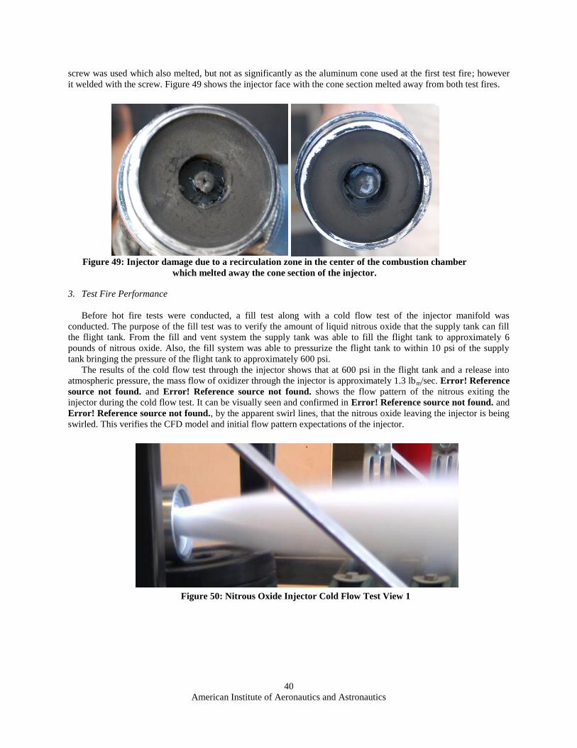
3. Test Fire Performance
Before hot fire tests were conducted, a fill test along with a cold flow test of the injector manifold was
conducted. The purpose of the fill test was to verify the amount of liquid nitrous oxide that the supply tank can fill
the flight tank. From the fill and vent system the supply tank was able to fill the flight tank to approximately 6
pounds of nitrous oxide. Also, the fill system was able to pressurize the flight tank to within 10 psi of the supply
tank bringing the pressure of the flight tank to approximately 600 psi.
The results of the cold flow test through the injector shows that at 600 psi in the flight tank and a release into
atmospheric pressure, the mass flow of oxidizer through the injector is approximately 1.3 lbm/sec. Error! Reference
source not found. and Error! Reference source not found. shows the flow pattern of the nitrous exiting the
injector during the cold flow test. It can be visually seen and confirmed in Error! Reference source not found. and
Error! Reference source not found., by the apparent swirl lines, that the nitrous oxide leaving the injector is being
swirled. This verifies the CFD model and initial flow pattern expectations of the injector.
Figure 50: Nitrous Oxide Injector Cold Flow Test View 1
Figure 49: Injector damage due to a recirculation zone in the center of the combustion chamber
which melted away the cone section of the injector.

American Institute of Aeronautics and Astronautics
41
The first test of the HM4 rocket motor was conducted on May 11, 2010 and resulted in a combustion chamber
over-pressurization. This over-pressurization occurred 0.2 seconds after ignition due to a premature release of the
NOX. Analysis and evaluation of the combustion chamber failure showed that release of the nitrous oxide must be
delayed until the APCP ignition grain has completely burned. The over-pressurization occurred as the high pressure
nitrous oxide came into contact with the combusting APCP grain; this high pressure contact resulted in an
atomization of the APCP grain and a violent flash of extremely high speed combustion. This failure analysis was
verified when small pieces of unburned APCP ignition grain were found in the test area, and with further ignition
testing. A still image from the test video is shown in Error! Reference source not found..
From the ignition testing it was determined that a smaller amount of APCP is sufficient to start the motor, and
the size of the APCP ignition grain has no significant impact on the regression rate or mass flux of the fuel. The only
impact of the APCP grain size is on the wait time between ignition and release of the nitrous oxide. Previously, 50
grams of 54mm APCP grain was used to ignite the motor; following the ignition testing the APCP grain was
reduced to approximately 10 grams.
Error! Reference source not found. shows the damage as a result of the over-pressurization. The chamber
failed at the forward end by the injection manifold where the ignition grain was located. Fortunately, only a few
pieces of hardware were damaged including the single use graphite nozzle, the combustion chamber, and the base
piece of the two piece injection manifold. It was decided to reconstruct the combustion chamber at a shorter length
to fit three 4.5 inch long fuel grains. The base piece of the injection manifold was also increased in length to provide
better structural support of the thrust load for testing.
Figure 52: Combustion Chamber Over Pressurization
Figure 51: Nitrous Oxide Cold Flow Test View 2

American Institute of Aeronautics and Astronautics
42
The first successful test of the motor conducted on May 25, 2010 resulted in 247 lbf of peak thrust, 212 lbf of
average thrust for 6 seconds; the test is shown in Error! Reference source not found.. This yielded a specific
impulse of 160 seconds and a total impulse of 1,400 lbf-seconds (6228 N-s), placing HM4 in the low M-class for
amateur rocket motors. Much of the data obtained from this test was used to validate and compare with our
computer model. An oxidizer mass flux of 1.13 lbm per second was obtained with a total oxidizer mass of 6.8 lbm at
an average of 500 psig. The fuel regressed at a mean rate of 2.92 mm per second. This high regression rate resulted
in a fuel mass flux of 0.189 lbm per second.
The second successful test was conducted on June 1, 2010 and resulted in a peak thrust of 338 lbf and an average
thrust of 260 lbf for 6 seconds. This test yielded a specific impulse of 200 seconds and a total impulse of 1,623 lbf-
seconds (7,260 N-s). This test duplicated the same test conditions as the first and obtained nearly identical results;
the only differences were due to the changes in tank conditions. A tank mass of 7 lbm of nitrous oxide was obtained
at an initial 588 psig. An oxidizer mass flux of 1.104 lbm per second and a fuel mass flux of 0.170 lbm per second
were obtained yielding an average mixture ratio of 6.5. Error! Reference source not found. summarizes all of the
test results in English units and Error! Reference source not found. summarizes the data in SI units.
Figure 54: Successful Test Fire
Figure 53: Combustion Chamber Damage

American Institute of Aeronautics and Astronautics
43
B. Analysis
1. Regression Analysis
Initial estimates for the regression rate of around 1 to 1.5 mm per second were taken from classical hybrid
models located in Chiaverini14
pending empirical data from testing. Once two tests were conducted and empirical
regression rates were found to be in excess of 2 mm per second our own regression rate was derived. Utilizing the
basic regression model in Eq. (39) and the observed regression rates from the two test fires, our own empirical
constants, or a and n values, were determined to generate a regression prediction based on the oxidizer mass flux,
Gox. From our data we obtained a value of 0.027909 and an n value of 11.607 to get Eq. (40).
(39)
(40)
Other regression models were considered for use in our analysis but didn‟t match well with our test setup. It was
found that each regression model is derived specifically for each test setup to determine the relationships between
the various parameters being tested; these parameters include injection method, fuel and oxidizer combination, and
combustion process. Our test setup is very unique due to its custom 12 port self-impinging swirl injector and fuel
composition. Further analysis into higher fidelity and complex regression models to accurately predict the regression
rate as a function of length down the combustion chamber would benefit further experimentation in injection
methods.
2. Performance Analysis
The rocket‟s performance after each test fire is calculated using equations from Sutton15
. Since the transient data
in regards to tank mass is ridiculously noisy the average mass flow of oxidizer and fuel are used to calculate average
oxidizer to fuel ratio and Isp. Specific results are tabulated in Error! Reference source not found..
From the MATLAB model, the overall thrust curve results are shown in Figure 55. This transient thrust
prediction almost matches the experimental results from the first successful test fire. The model showed an average
oxidizer mass flow of just under 1.1 lbm/sec and an average regression rate of 0.085 inch/sec which matches closely
with averaged test results of 1.117 lbm/sec and 0.102 inch/sec respectively. The tank pressure during testing and the
14
(Chiaverini and Kuo 2007) 15
(Sutton and Biblarz 2001)
Table 5. Summary of Test Results in SI Units
Test
Peak
Thrust
(N)
Average
Thrust
(N)
Burn
Time
(sec)
Total
Impulse
(N-sec)
Specific
Impulse
(sec)
Regression
Rate
(mm/sec)
Oxidizer
Mass
Flux
(g/sec)
Fuel
Mass
Flux
(g/sec)
O/F
Ratio
1 1,099 943 6 6,228 160 2.929 512.6 85.7 5.98
2 1,503 1,157 6 7,219 200 2.235 500.8 77.1 6.49
Table 4. Summary of Test Results in English Units
Test
Peak
Thrust
(lbf)
Average
Thrust
(lbf)
Burn
Time
(seconds)
Total
Impulse
(lbf-sec)
Specific
Impulse
(sec)
Regression
Rate
(in/sec)
Oxidizer
Mass
Flux
(lbm/sec)
Fuel
Mass
Flux
(lbm/sec)
O/F
Ratio
1 247 212 6 1,400 160 0.1153 1.130 0.189 5.98
2 338 260 6 1,623 200 0.0880 1.104 0.170 6.49
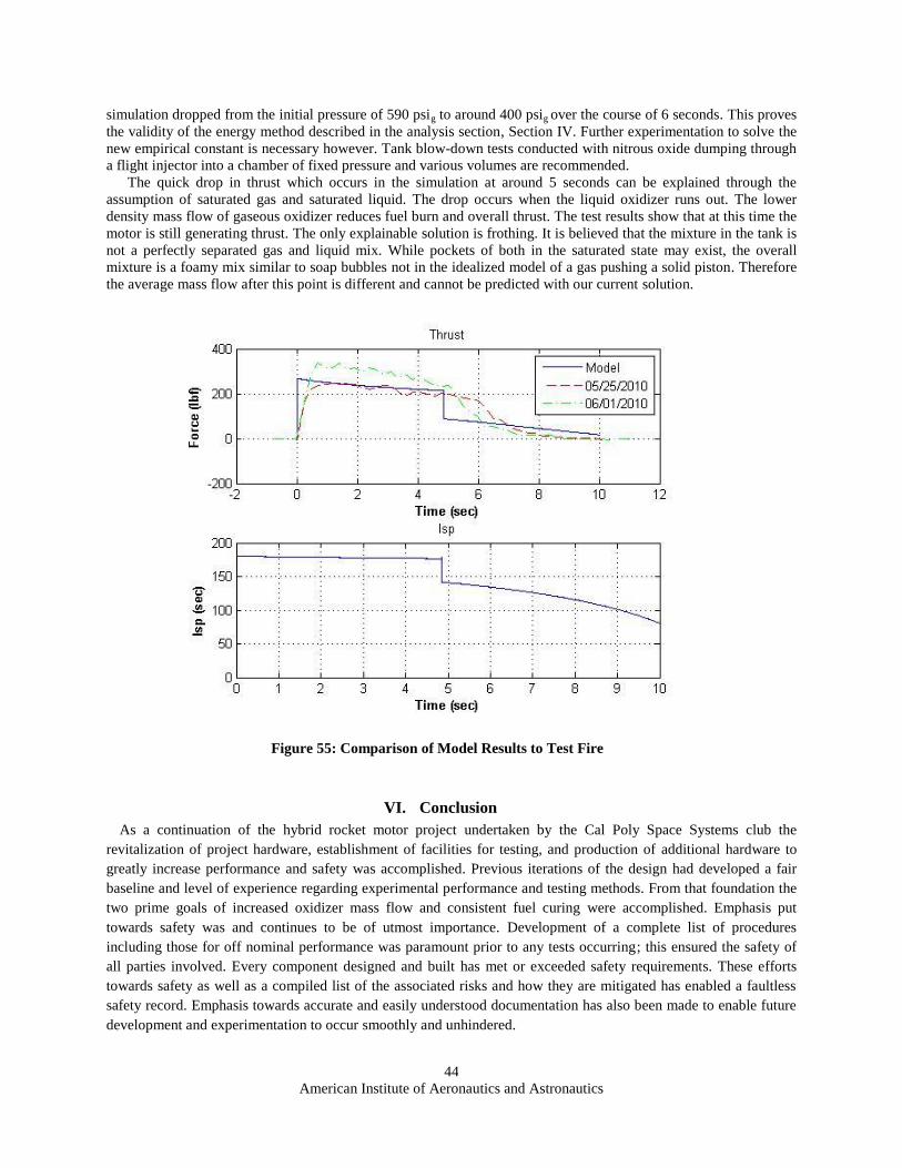
American Institute of Aeronautics and Astronautics
44
simulation dropped from the initial pressure of 590 psig to around 400 psig over the course of 6 seconds. This proves
the validity of the energy method described in the analysis section, Section IV. Further experimentation to solve the
new empirical constant is necessary however. Tank blow-down tests conducted with nitrous oxide dumping through
a flight injector into a chamber of fixed pressure and various volumes are recommended.
The quick drop in thrust which occurs in the simulation at around 5 seconds can be explained through the
assumption of saturated gas and saturated liquid. The drop occurs when the liquid oxidizer runs out. The lower
density mass flow of gaseous oxidizer reduces fuel burn and overall thrust. The test results show that at this time the
motor is still generating thrust. The only explainable solution is frothing. It is believed that the mixture in the tank is
not a perfectly separated gas and liquid mix. While pockets of both in the saturated state may exist, the overall
mixture is a foamy mix similar to soap bubbles not in the idealized model of a gas pushing a solid piston. Therefore
the average mass flow after this point is different and cannot be predicted with our current solution.
VI. Conclusion
As a continuation of the hybrid rocket motor project undertaken by the Cal Poly Space Systems club the
revitalization of project hardware, establishment of facilities for testing, and production of additional hardware to
greatly increase performance and safety was accomplished. Previous iterations of the design had developed a fair
baseline and level of experience regarding experimental performance and testing methods. From that foundation the
two prime goals of increased oxidizer mass flow and consistent fuel curing were accomplished. Emphasis put
towards safety was and continues to be of utmost importance. Development of a complete list of procedures
including those for off nominal performance was paramount prior to any tests occurring; this ensured the safety of
all parties involved. Every component designed and built has met or exceeded safety requirements. These efforts
towards safety as well as a compiled list of the associated risks and how they are mitigated has enabled a faultless
safety record. Emphasis towards accurate and easily understood documentation has also been made to enable future
development and experimentation to occur smoothly and unhindered.
Figure 55: Comparison of Model Results to Test Fire

American Institute of Aeronautics and Astronautics
45
The revisit to the oxidizer feed and injection system has allowed for a complete redesign and reconstruction with
safety rated components. Drag in flow passages and insertion losses through controls were reduced drastically by
reducing the number of fittings and components from the tank to the injector. In addition, atomization and mixing of
the oxidizer was improved using a self-impinging swirl injection method. Fuel composition and consistency have
also reached a new level. Uniformity and consistency of the cure were increased in addition to reducing bubble
formation. Fuel mixture research and process development have been established to expedite the fuel curing process
and facilitate future fuel research. Finally, a transient computer model has been developed to predict future test fires
and to optimize the motor. Despite all these tremendous efforts to establish this foundation there is still work to be
completed. Continued hot fire testing will provide insight into the yet fully understood phenomena occurring and
establish a much more accurate transient model of the nitrous oxide tank and fuel grain regression; these models will
enable more accurate performance predictions.
This project taught the benefits of experimentation. Most of the solutions sought did not have clear answers.
Trouble was often encountered in finding simple conceptual answers to questions and instead high fidelity over-
specific analysis had to be developed. Initial experiments were all accomplished using everyday materials to
qualitatively solve issues particularly those of injector flow pattern and cure consistency. Every increase in fidelity
and quality of experiment provided substantial additional information used to design and build the current iteration
of the motor; however, without the smaller and much simpler experiments to give guidance early efforts made
towards the final design would have been misguided. In contrast, the use of heritage hardware and documentation
provided much frustration due to its lack of accuracy. Care must be taken to ensure all conclusions are rooted in
scientific fact and found with sound reasoning. When doubt comes to mind one must not underestimate the value of
simple basic experiments and calculations from the engineering fundamentals to provide guidance. Validation and
verification of all decisions and designs ensures optimum results.
Our hopes are that this project sees further research. Much more testing can and should be done to further
investigate and model what is occurring. Some specific areas for future study and experimentation include varying
fuel grain geometries, fuel additives, injection swirl angles, number of injection ports, and nozzle geometries and
types. As always, funding puts limitations on the amount and quality of work that gets done; one must always be
economical in purchases and consider items of greatest utility. Manufacturing is a lengthy and time consuming
process, so schedules, commitment, and responsibility become vital.
In summary, documentation and definitive results in predicting performance of a hybrid rocket motor were
attained without injury or loss of property while passing on the engineering knowledge learned through experience
to the next generation of engineers.

American Institute of Aeronautics and Astronautics
46
Appendix
I. Method for Machining Angled Holes on Injector
i. Angle the mill head to the requisite angle
ii. Put in the Tool
iii. Use the top of the center cone as the reference point (Use a CAD program to find the required X and Y
travel to locate the holes)
iv. Use Drill Press lever on Mill to perform function
v. Tool Order
1. 1/8 inch flat end mill: Cut only what is required to make a flat surface.
2. #3 Center Drill (May need to be a few inches long to clear part): Drill until the flare hits the part
3. 3/32 Drill Bit or the required size: Drill until you feel no more material removal.

American Institute of Aeronautics and Astronautics
47
II. Test Procedures
Test Procedures (Revised June 5, 2010)
Safety Features:
Safe Propellants:
The hybrid propellants are non-explosive materials that are non-corrosive and relatively
safe under standard conditions of pressure and temperature. HTPB is a rubber that is
very safe and easy to store. Nitrous Oxide Plus requires careful handling because of its
pressurized storage but is no more dangerous than any other compressed gas.
Secure Ignition:
Hybrid motors will not combust unless there is sufficient heat available to melt the HTPB
and break oxygen from the NOX. This means that if there was an oxidizer flow failure
and Nitrous Oxide was released into the combustion chamber prematurely there would be
NO COMBUSTION. Without the heat and pressure from the ignition system there
would be no chemical reaction between the HTPB and the Nitrous Oxide. With our
redundant safety locks controlling the ignition system we can safely handle the hybrid
motor without fear of spontaneous combustion.
Pressure Relief Valves:
The addition of 1800 psi pressure relief pop-off valves on the oxidizer feed assembly
located at the tank manifold prevent the system from reaching the yield pressure of 3000
psi. Expected maximum pressure is 800 psi while all fittings and components are rated at
3000 psi, the 1800 psi relief valves ensure the yield pressure is never reached.
Safety Factors:
Oxidizer tank safety factor: 10.48
(1850 psi design / maximum of 600 psi expected) * (3.4 built in safety factor)
Solenoid safety factor: 3.67
(2200 psi design / maximum of 600 psi expected)
Ball Valve safety factor: 5
(3000 psi design / maximum of 600 psi expected)
Hosing safety factor: 5
(3000 psi design / maximum of 600 psi expected)
Fittings safety factor: 5
(3000 psi design / maximum of 600 psi expected)
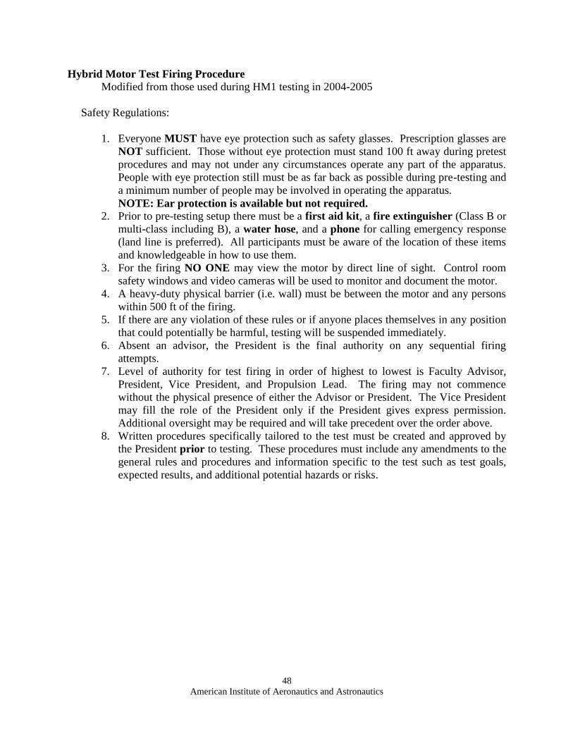
American Institute of Aeronautics and Astronautics
48
Hybrid Motor Test Firing Procedure
Modified from those used during HM1 testing in 2004-2005
Safety Regulations:
1. Everyone MUST have eye protection such as safety glasses. Prescription glasses are
NOT sufficient. Those without eye protection must stand 100 ft away during pretest
procedures and may not under any circumstances operate any part of the apparatus.
People with eye protection still must be as far back as possible during pre-testing and
a minimum number of people may be involved in operating the apparatus.
NOTE: Ear protection is available but not required.
2. Prior to pre-testing setup there must be a first aid kit, a fire extinguisher (Class B or
multi-class including B), a water hose, and a phone for calling emergency response
(land line is preferred). All participants must be aware of the location of these items
and knowledgeable in how to use them.
3. For the firing NO ONE may view the motor by direct line of sight. Control room
safety windows and video cameras will be used to monitor and document the motor.
4. A heavy-duty physical barrier (i.e. wall) must be between the motor and any persons
within 500 ft of the firing.
5. If there are any violation of these rules or if anyone places themselves in any position
that could potentially be harmful, testing will be suspended immediately.
6. Absent an advisor, the President is the final authority on any sequential firing
attempts.
7. Level of authority for test firing in order of highest to lowest is Faculty Advisor,
President, Vice President, and Propulsion Lead. The firing may not commence
without the physical presence of either the Advisor or President. The Vice President
may fill the role of the President only if the President gives express permission.
Additional oversight may be required and will take precedent over the order above.
8. Written procedures specifically tailored to the test must be created and approved by
the President prior to testing. These procedures must include any amendments to the
general rules and procedures and information specific to the test such as test goals,
expected results, and additional potential hazards or risks.

American Institute of Aeronautics and Astronautics
49
Hybrid Motor Test Fire Procedures:
1. Roles during Test Fire
1.1. Test Control (Propulsion Lead): Command and control during firing.
1.2. Fire Control: Operates all filling, venting, and firing valves as well as the ignition
circuit. Will shut off all control circuits in the event of an Abort.
1.3. Safety Control: Will be the only person to approach any fire with an appropriate fire
extinguisher after being instructed to do so by Test Control.
1.4. Range Safety (multiple): Stands watch at predetermined positions to prevent
bystanders from approaching the test area. Will have radio communication to Test
Control.
1.5. Sensor Control: In charge of all sensors and data acquisition during the test.
2. Sensor Calibration
2.1. Pressure Transducers
NOTE: Pressure transducers only need be checked to ensure their calibration is still
accurate; they do not need to be calibrated each test fire.
2.1.1. Open the “CPSS Hybrid Program” LabVIEW file and power the sensors to 10 V
DC.
2.1.2. Obtain a reference voltage for atmospheric pressure.
2.1.3. Connect a compressed air line to the pressure transducer through its valve
assembly.
2.1.4. Increase pressure on the compressor in increments of 5 or 10 psi, record each
voltage output by the transducer.
2.1.5. Apply a linear fit and input the slope and y-intercept into the LabVIEW block
diagram to obtain psi gauge pressure readings.
2.1.6. Repeat for the 2nd
pressure transducer.
2.2. Load Cells
NOTE: Load cells need to be calibrated for each test fire to ensure accuracy.
2.2.1. Ensure no load is applied to the load cell and record reference voltage.
2.2.2. Apply weights to the load cell using rope in increments of 5 to 10 pounds, record
each voltage output by load cell.
2.2.3. Apply a linear fit and input the slope and y-intercept into the LabVIEW block
diagram to obtain lbf load readings.
2.2.4. Repeat for the 2nd
load cell.
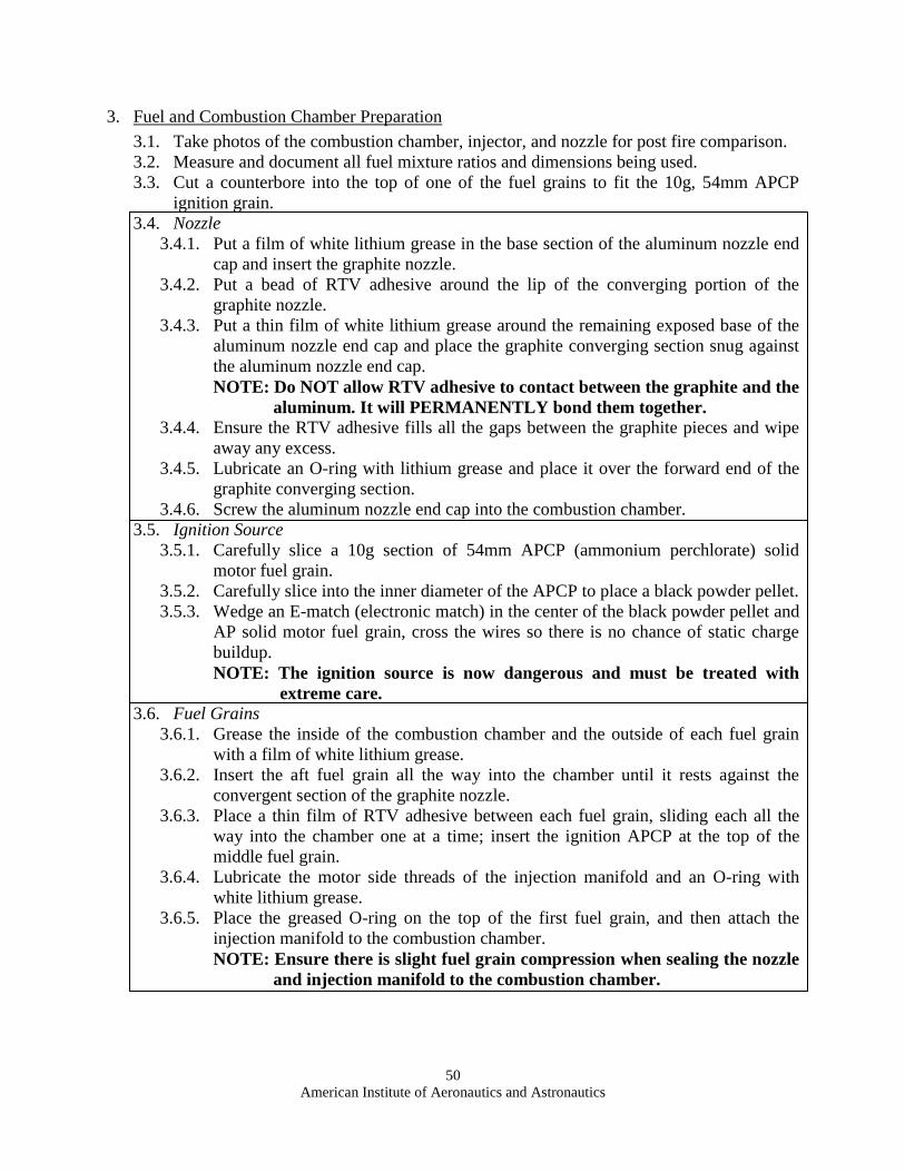
American Institute of Aeronautics and Astronautics
50
3. Fuel and Combustion Chamber Preparation
3.1. Take photos of the combustion chamber, injector, and nozzle for post fire comparison.
3.2. Measure and document all fuel mixture ratios and dimensions being used.
3.3. Cut a counterbore into the top of one of the fuel grains to fit the 10g, 54mm APCP
ignition grain.
3.4. Nozzle
3.4.1. Put a film of white lithium grease in the base section of the aluminum nozzle end
cap and insert the graphite nozzle.
3.4.2. Put a bead of RTV adhesive around the lip of the converging portion of the
graphite nozzle.
3.4.3. Put a thin film of white lithium grease around the remaining exposed base of the
aluminum nozzle end cap and place the graphite converging section snug against
the aluminum nozzle end cap.
NOTE: Do NOT allow RTV adhesive to contact between the graphite and the
aluminum. It will PERMANENTLY bond them together.
3.4.4. Ensure the RTV adhesive fills all the gaps between the graphite pieces and wipe
away any excess.
3.4.5. Lubricate an O-ring with lithium grease and place it over the forward end of the
graphite converging section.
3.4.6. Screw the aluminum nozzle end cap into the combustion chamber.
3.5. Ignition Source
3.5.1. Carefully slice a 10g section of 54mm APCP (ammonium perchlorate) solid
motor fuel grain.
3.5.2. Carefully slice into the inner diameter of the APCP to place a black powder pellet.
3.5.3. Wedge an E-match (electronic match) in the center of the black powder pellet and
AP solid motor fuel grain, cross the wires so there is no chance of static charge
buildup.
NOTE: The ignition source is now dangerous and must be treated with
extreme care.
3.6. Fuel Grains
3.6.1. Grease the inside of the combustion chamber and the outside of each fuel grain
with a film of white lithium grease.
3.6.2. Insert the aft fuel grain all the way into the chamber until it rests against the
convergent section of the graphite nozzle.
3.6.3. Place a thin film of RTV adhesive between each fuel grain, sliding each all the
way into the chamber one at a time; insert the ignition APCP at the top of the
middle fuel grain.
3.6.4. Lubricate the motor side threads of the injection manifold and an O-ring with
white lithium grease.
3.6.5. Place the greased O-ring on the top of the first fuel grain, and then attach the
injection manifold to the combustion chamber.
NOTE: Ensure there is slight fuel grain compression when sealing the nozzle
and injection manifold to the combustion chamber.

American Institute of Aeronautics and Astronautics
51
4. Oxidizer System Preparation
4.1. Attach the brass hex tank manifold to the flight tank using a Teflon washer.
NOTE: NEVER use Teflon tape for connecting the tank manifold to the flight
tank.
4.2. Roll up BOTH lab doors.
4.3. All hose and fittings (NPT Threads) must be sealed with Teflon tape but not allow
exposure of the Teflon to the flow. Leave the first 1-3 threads exposed to ensure
compliance.
NOTE: NEVER use Teflon tape for CGA connections or other straight threads.
4.4. Supply Assembly
4.4.1. Wheel the NOX and GN2 (gaseous Nitrogen) supply tanks into lab and securely
strap them to the pole.
4.4.2. Verify that the blue manual valve on fill hose is CLOSED.
4.4.3. Connect the regulator to the GN2 supply tank.
4.4.4. Connect the fill hose to the GN2 regulator.
4.5. Vent Assembly
4.5.1. Verify the vent solenoid circuitry, test operation, and ensure it is CLOSED.
NOTE: Solenoid circuit gets VERY HOT during use. Minimize continuously
powering the solenoid to avoid overheating.
4.5.2. Connect the pressure transducer to the T-fitting.
4.5.3. Connect the needle valve to vent solenoid.
NOTE: Needle valve should be fully OPEN.
4.5.4. Connect the vent assembly to the brass hex tank manifold at the quick disconnect.
4.5.5. Connect the pressure transducer to the vent pressure wiring channel.
4.5.6. Connect the solenoid to the vent valve wiring channel
4.6. Feed Assembly
4.6.1. Connect the steel braided feed hose to the brass hex tank manifold.
4.6.2. Connect the fire valve motor to power and the control circuit.
4.6.3. Power the fire valve circuit, check for audible actuation of 2 control relays and
illumination of its indicator lights.
NOTE: GREEN indicates the valve is open, and RED indicates closed.
4.6.4. Test the fire valve actuation by cycling it open and closed.
NOTE: Visually inspect that the ball valve and the micro switches for wear.
4.6.5. Connect the free end of the steel braided feed hose to the fire valve, ensuring the
fire valve is CLOSED.
4.6.6. Connect the ½” hex brass pipe to the fire valve on the motor side.
4.6.7. Connect the tank load cell to the load cell wiring channel and record the empty
weight reading.

American Institute of Aeronautics and Astronautics
52
4.7. Fill Assembly
4.7.1. Verify the fill solenoid circuitry, test operation, and ensure it is CLOSED.
4.7.2. Connect the pressure transducer to the T-fitting.
4.7.3. Connect the fill hose to the fill assembly.
4.7.4. Connect the fill assembly to the brass hex tank manifold at the quick disconnect.
4.7.5. Connect the pressure transducer to the tank pressure wiring channel.
4.7.6. Connect the solenoid to the fill valve wiring channel.
5. Nitrogen Flush
5.1. OPEN the GN2 supply tank valve.
5.2. OPEN the GN2 regulator to 150 psig.
5.3. OPEN the blue manual valve on the fill hose.
NOTE: Ensure that the needle valve on the vent assembly is still fully OPEN.
5.4. Remove all personnel from the test area AND shut the control room doors.
5.5. ARM the Fill System and OPEN the fill solenoid from the control room until the tank
reaches 150 psig.
5.6. OPEN the vent solenoid for 5 seconds.
NOTE: This cleans out the vent system 5.7. DISARM the fill system.
5.8. CLOSE the GN2 supply tank valve.
5.9. Remove all personnel from the test area AND shut the control room doors.
5.10. ARM the fire system and OPEN the fire Valve until the system completely
depressurizes.
NOTE: This cleans out the oxidizer feed system. 5.11. DISARM the fire system and CLOSE the GN2 regulator and blue manual valve on the
fill hose.
5.12. Disconnect the fill hose from the GN2 regulator.
6. Secure to Test Stand
6.1. Apply Teflon tape to the hex brass ½ inch NPT pipe from the fire valve.
6.2. Slide the combustion chamber into the test stand mounts and tightly secure itto the test
stand.

American Institute of Aeronautics and Astronautics
53
7. Fill Procedure
7.1. Check NOX Flow
7.1.1. Connect the fill hose to the NOX supply tank
7.1.2. OPEN the NOX supply tank valve.
7.1.3. Check for leaks.
NOTE: Propulsion Lead must decide whether any leaks are acceptable
before firing. The Advisor and President have the power to
overrule the Propulsion Lead’s decision. Unacceptable leaks are
those which result in visible white exhaust or bubbling of
evaporating oxidizer. An example of an acceptable leak would be
one in which the exhaust is clear.
7.1.4. OPEN the blue manual valve on the fill hose.
7.1.5. Check for leaks.
7.1.6. Remove all personnel from the test area AND shut the control room doors.
7.1.7. ARM the fill system and OPEN the fill and vent solenoid from control room until
100 psig in the tank is reached.
7.1.8. DISARM the fill system and check for leaks.
NOTE: Leaks may occur due to shrinkage of fittings from the extreme cold
of NOX.
7.1.9. Remove all personnel from the test area AND shut the control room doors.
7.2. Flight Tank Filling
7.2.1. ARM the fill system and OPEN the fill and vent solenoid from control room until
a steady state pressure is reached (near 600 psig). Watch the fluid exiting the vent
assembly and listen for audible changes in fluid flow.
NOTE: Filling process takes several minutes. Watch the pressure levels and
vented fluid carefully. Cycle the valves open and closed and check for
leaks as necessary. 7.2.2. DISARM the fill system and check for leaks due to fitting shrinkage.
7.2.3. CLOSE the NOX supply tank valve.
7.2.4. Disconnect the fill assembly from the brass hex tank manifold at the quick
disconnect.
NOTE: Be VERY CAREFUL when disconnecting the fill assembly; it is very
difficult to disconnect and a small burst if nitrous oxide will be
released as the quick disconnects shut. Wearing gloves and a full face
shield is recommended.
7.2.5. Record the full weight reading from tank load cell.
7.3. Fill Hose Purge
7.3.1. Connect the fill assembly quick disconnect to the purge connector.
7.3.2. Secure the purge connector to ensure it sprays outside.
7.3.3. Remove all personnel from the test area AND shut the control room doors.
7.3.4. ARM the fill system and OPEN the fill solenoid until the fill hose is empty.
7.3.5. DISARM the fill system and CLOSE the blue manual valve.
7.3.6. Disconnect the fill hose and wheel the tanks outside the test area and secure for
the test fire.

American Institute of Aeronautics and Astronautics
54
8. Firing Procedure
8.1. Fire Preparation
NOTE: Read Section 8.3 PRIOR to ANY test fire preparation.
8.1.1. Connect thrust load cell to the tank pressure wiring channel.
NOTE: Check that the thrust reading is zero to ensure accurate data
acquisition.
8.1.2. Confirm the firing circuit is DISARMED.
8.1.3. Short the 2 alligator clips by touching them together ensuring no residual voltage
differential lies across them.
8.1.4. Connect igniter leads to ignition alligator clips.
NOTE: Take special care to avoid the exhaust area behind the motor.
8.1.5. START the video documentation.
8.1.6. Remove all personnel from the test area AND shut the control room doors.
8.2. Safety Check
8.2.1. Confirm that test area is clear of people and debris.
8.2.2. Test Control confirms with Sensor, Fire, and Safety Control with a GO/NO GO
for test.
NOTE: Sensor control checks all pressure readings for nominal values and
Fire Control checks all valves to ensure they are in the correct position.
8.2.3. Test Control confirms with each Range Safety that all bystanders are clear of the
test area with a GO/NO GO for test.
8.2.4. Test Control declares via radio “Any radio traffic by personnel other then the Test
Control will be interpreted as an abort command from this point on.”
8.3. Test Fire
8.3.1. Fire Control ARMS the firing circuit.
8.3.2. Sensor Control STARTS the LabVIEW data acquisition.
8.3.3. Test Control begins audible countdown from 10 seconds.
8.3.4. Countdown transmitted on radio until 5 seconds then clear radio for any abort
command.
8.3.5. At 0 Test Control declares “IGNITION” and Fire Control ignites the motor.
8.3.6. Wait until the flames from the APCP ignition die down and are almost out, then
Test Control declares “NITROUS ON” and Fire Control OPENS the fire valve.
8.3.7. Visually confirm the valve opens with the GREEN indicator light and that the
motor starts.
NOTE: If motor DOES NOT start, Test Control declares “ABORT” See
Section 11.
9. Shutdown
9.1. After the flight tank empties, the Test Control declares “SHUTDOWN”.
9.2. Fire Control DISARMS all circuits.
9.3. Sensor Control STOPS the LabVIEW data acquisition.
9.4. Test Control or Safety Control STOPS the video documentation.

American Institute of Aeronautics and Astronautics
55
10. Post Firing Inspection
10.1. All personnel wait at least 5 minutes before entering the test area following inspection
by Safety Control or Test Control.
10.2. Nitrogen Purge
10.2.1. Wheel the GN2 supply tank into the lab and secure it to the pole.
10.2.2. Disconnect the motor from the fire valve.
NOTE: Be careful because the motor casing will be VERY HOT.
10.2.3. Attach the fill hose to the GN2 regulator.
10.2.4. Connect the fill assembly to the brass hex tank manifold at the quick disconnect.
10.2.5. Allow the motor to cool before attempting to remove the injector, nozzle, or fuel
grains.
10.2.6. Follow the GN2 flush procedures in Section 5.
10.3. Component Inspection
10.3.1. Inspect the combustion chamber, nozzle, oxidizer feed assembly, and fire valve
for damage.
10.3.2. Remove fuel grains for performance evaluation, weighing, and dimension
measurements.
10.3.3. Remove the injection manifold and inspect for damage.
10.3.4. Document all components with pictures for pre-test comparison.
10.4. Clean the oxidizer system component threads with distilled water and simple green
and tape over all connections to ensure no contaminants enter.
10.5. Clean the motor and injector with Simple Green and paper towels.
11. Abort
11.1. If motor does not ignite or any abnormalities occur, the Test Control will declare
“ABORT”.
11.2. Any abort will be declared audibly and via radio.
11.3. Fire Control will immediately DISARM all circuits.
11.4. All personnel will stay at their stations until Test Control declares the test area safe.
11.5. Safety Control is the only exception and may be instructed to extinguish a fire by the
Test Control.

American Institute of Aeronautics and Astronautics
56
III. MATLAB Codes (Miscellaneous Functions Provided Upon Request to the Authors)
a. Injector Model (Huzel and Huang 1992)
% Alexander Athougies % CPSS % % Calculates Nox mass flow through an injector % % INPUTS: % 1) Ninj = number of injectors % 2) dinj = injector diameter (in) % 3) Kinj = head loss coefficient % 4) Psource = source pressure (psia) % 5) Pdump = pressure of dump point (psia) % 6) rho = liquid density (lbm/in^3) % % OUT: % 1) dm = mass flow (lbm/sec)
function dm = Injector(Ninj, dinj, Kinj, Psource, Pdump, rho)
rho = rho * (12^3); % lbm / ft^3
if Psource < Pdump dm = -(Ninj*pi/4*dinj^2)*(2.238*Kinj/rho/(Pdump - Psource))^(-1/2); else dm = (Ninj*pi/4*dinj^2)*(2.238*Kinj/rho/(Psource - Pdump))^(-1/2); end
end
b. Nozzle Model [(Sutton and Biblarz 2001) and (Zucrow and Hoffmann 1976)]
% Alexander Athougies % CPSS % % Calculates Nozzle Thrust and Isp given Dimensions and Mass Flow % % INPUTS: % 1) dm = mass flow expected(lbm/sec) % 2) P0 = chamber pressure (psia) % 3) T0 = chamber temperature (R) % 4) At = throat area (in^2) % 5) Ae = exit Area (in^2) % 6) Aet = intake Area (in^2) % 7) Patm = Atmospheric Pressure (psia) % 8) Re = gas constant (in-lbf/lbm-R) % 9) gamma = ratio of specific heats % % OUT: % 1) F = force (lbf) % 2) Isp = specific impulse (sec) % 3) dme = real mass flow (lbm/sec)
function [F, Isp,dme] = nozzlecalc(dm, P0, T0, At, Ae, Aet, Patm, Re,
gamma)

American Institute of Aeronautics and Astronautics
57
Knoz = 50; dme = 0; a = 12*sqrt(gamma*Re*T0/12*32.2); rho = sqrt(P0/Re/T0); dt = 2*sqrt(At/pi());
% Find M1 M1 = dm/(a*rho*Aet);
% Find Theoretical Compression Ratio E1 = 1 / M1*((2/(gamma+1))*(1+(gamma-1)/2*M1^2))^((gamma + 1) / 2 / (gamma
- 1)); % 4.29 - Zucrow
% Find Real E E = Aet / At; E2r = Ae / At;
% check choking if (E1*0.90) <= E dme =
At*P0/sqrt(gamma*Re*T0)*(gamma*sqrt((2/(gamma+1))^((gamma+1)/(gamma-1))));
% 4.38 to 4.39 Zucrow Me = 1; E2 = 0; while E2 < E2r E2 = 1 / Me*((2/(gamma+1))*(1+(gamma-1)/2*Me^2))^((gamma + 1) / 2 /
(gamma - 1)); % 4.29 - Zucrow Me = Me + .001; end ve = Me*a; % in / sec Pe = P0*(1+(gamma - 1)/2*Me^2)^(-gamma / (gamma - 1)); % 4.26 Zucrow % while Pe < Patm % Pe = P0*(1+(gamma - 1)/2*Me^2)^(-gamma / (gamma - 1)); % 4.26
Zucrow % Me = Me - .001; % end elseif E1 > E % no choked dme = Injector(1, dt, Knoz, P0, Patm, rho); ve = dme/At/rho; Me = ve / a; Pe = P0*(1+(gamma - 1)/2*Me^2)^(-gamma / (gamma - 1)); end
% Find Thrust if dm > 0 && dme > 0 F = dme*ve/32.2/12 + (Pe - Patm)*Ae; % lbf Isp = F / dme; % sec else F = 0; Isp = 0; dme = Injector(1, dt, 1, P0, Patm, rho); end

American Institute of Aeronautics and Astronautics
58
end
c. Hybrid Rocket Simulator
% Alexander Athougies % CPSS Hybrid Rocket % % Simulator (Rev. 8)... % % Assumptions: Isentropic, Adiabatic, Perfect Gas, Incompressible, % Constant Burn Temps, Combustions stops with fuel/ox (aka. no problems) % % function [t,Pt,Pc,rin,mox,mf,F,I,type,avgF] = HybridSim() function HybridSimRev8()
%% Housekeeping clc close all clear all
%% Inputs % % CPSS Hybrid % Simulation tburn = 10; % sec - simulation time
% Inital Conditions mox = 6.8; % lbm - Initial Oxidizer Mass - In Tank Vt = 295 + 24*pi/4*(.5^2); %in^3 - Tank Internal Volume + Line x = .05; % Quality of Mixture ( % vapor )
% Grain Geometry L = 13.465; % in - Grain Length rout = 3.49/2; % in - Outer Radius of Grain rinp = 1.8/2; % in - Inner Radius of Grain
% Nozzle Geometry rt = .7/2; % in - Radius of Nozzle Throat Vfree = 0; % in^3 - free space inside combustion chamber E2 = 5; % Nozzle Area Expansion Ratio
% Atmospheric Conditions Pc = 14.7; %psia - Initial Chamber Pressure Patm = Pc; %psia - Atmospheric Pressure Tatm = 505; % atmospheric Temp (R) g0 = 32.2; % ft/sec^2 - Gravity
% Grain Burn Characteristics a = .28; % Regression Variables - See Excel File n = .3;
% Injector Geometry dinj = 3/32; % in - diameter of injector(s) N = 12; % number of injectors Kinj = 44.25; % Injector Head Loss Coefficient

American Institute of Aeronautics and Astronautics
59
% Chemical Properties Dome = load('vapordome_nox_v2.mat'); % % Loaded From File % All Nitrous Vapor Dome Data under structure 'Dome' g1 = Dome.g1; % Nitrous gamma g2 = 1.2; % Exhaust gamma Rnos = 378.5862; % in-lbf / lbm-R (.1889 J / g-K) % Rex = function of O/F rhoNOSl = table(Dome.Temperature_E, Dome.density_E_l, Tatm); % Density of
Liquid Nitrous Oxide (lbm/in^3) rhoNOSg = table(Dome.Temperature_E, Dome.density_E_g, Tatm); % Density of
Gas Nitrous Oxide (lbm/in^3) rhoHTPB = .0325; % lbm / in^3 - http://www.braeunig.us/space/propel.htm rhoAIR = 4.34E-5; % lbm / in^3 - Density of Air at T = 20 degC Pt = table(Dome.Temperature_E, Dome.Pressure_E, Tatm); % Tank Pressure
(psia)
Dome.Af = 1.3; % Boiling Flux Factor
%% Givens % Nozzle Properties Aet = pi*rout^2; At = pi*rt^2; Ae = At * E2;
%% Calculate Initial Conditions Vox = (1 - x) * mox / rhoNOSl; % Oxidizer Volume (in^3) Vf = (rout^2 - rinp^2)*pi*L; % Fuel Mass Volume (in^3) mf = Vf * rhoHTPB; % lbm Vu = Vt - Vox; % Initial Ullage Volume (in^3) mair = (pi*L*rinp^2 + Vfree) * rhoAIR; % Mass of Air in Chamber (lbm) moxg = x * mox; % lbm moxl = (1-x) * mox; % lbm ChamberTemp = Tatm; % R Ptc = Pt; % Psia dmoxg = 0;
%% Initial Internal Energy hg = table(Dome.Temperature_E, Dome.enthalpy_E_g, Tatm); % BTU / lbm hl = table(Dome.Temperature_E, Dome.enthalpy_E_l, Tatm); % BTU / lbm ug = hg - Pt / rhoNOSg * 32.2 * 32.2 / 12 / 25037; % BTU / lbm ul = hl - Pt / rhoNOSl * 32.2 * 32.2 / 12 / 25037; % BTU / lbm Ut = moxg * ug + moxl * ul; % BTU
% %% In Progress Display % figure('Name','Display','NumberTitle','off') % hold on % display = plot(0,Pt,'rx','MarkerSize',10); % display2 = plot(0,Pc,'bx','MarkerSize',10); % legend('Tank','Chamber') % grid on % axis([0 tburn 0 800])
%% Main Loop
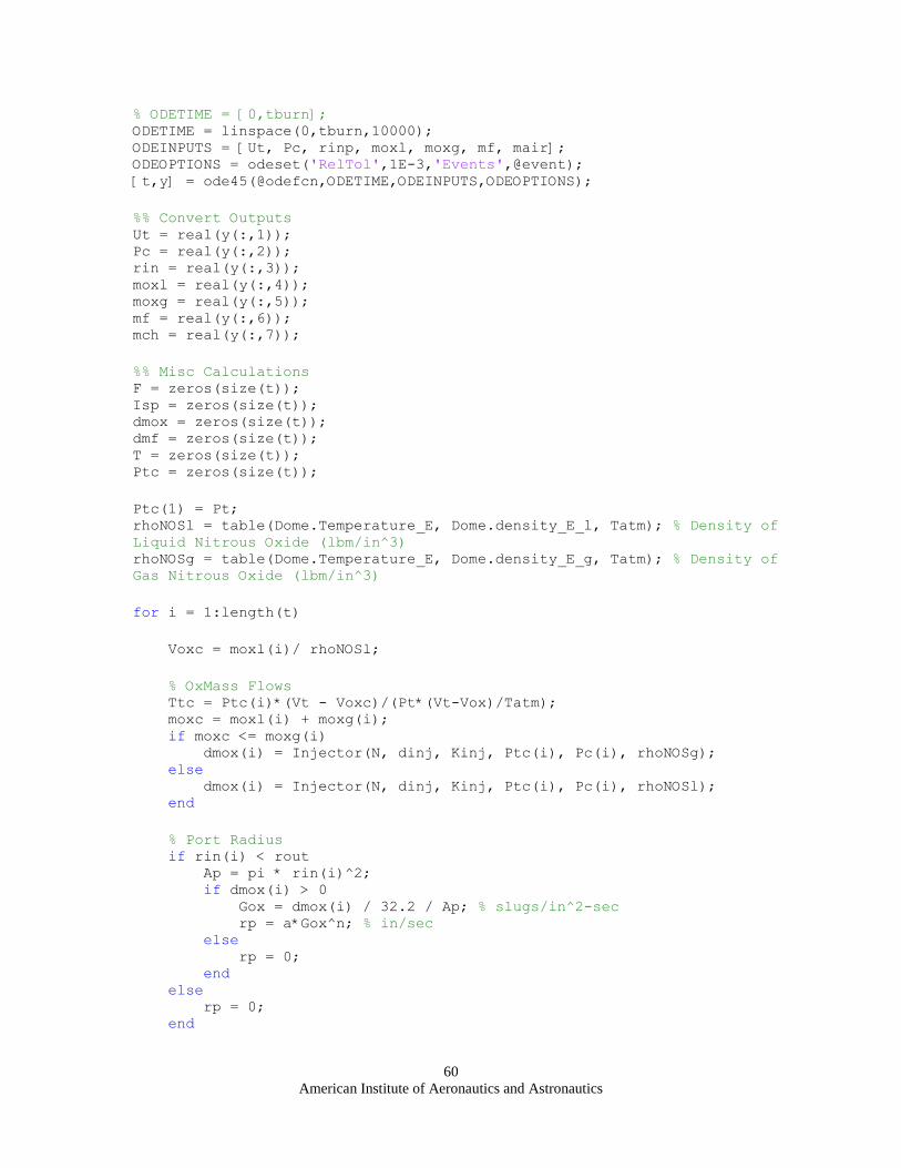
American Institute of Aeronautics and Astronautics
60
% ODETIME = [0,tburn]; ODETIME = linspace(0,tburn,10000); ODEINPUTS = [Ut, Pc, rinp, moxl, moxg, mf, mair]; ODEOPTIONS = odeset('RelTol',1E-3,'Events',@event); [t,y] = ode45(@odefcn,ODETIME,ODEINPUTS,ODEOPTIONS);
%% Convert Outputs Ut = real(y(:,1)); Pc = real(y(:,2)); rin = real(y(:,3)); moxl = real(y(:,4)); moxg = real(y(:,5)); mf = real(y(:,6)); mch = real(y(:,7));
%% Misc Calculations F = zeros(size(t)); Isp = zeros(size(t)); dmox = zeros(size(t)); dmf = zeros(size(t)); T = zeros(size(t)); Ptc = zeros(size(t));
Ptc(1) = Pt; rhoNOSl = table(Dome.Temperature_E, Dome.density_E_l, Tatm); % Density of
Liquid Nitrous Oxide (lbm/in^3) rhoNOSg = table(Dome.Temperature_E, Dome.density_E_g, Tatm); % Density of
Gas Nitrous Oxide (lbm/in^3)
for i = 1:length(t)
Voxc = moxl(i)/ rhoNOSl;
% OxMass Flows Ttc = Ptc(i)*(Vt - Voxc)/(Pt*(Vt-Vox)/Tatm); moxc = moxl(i) + moxg(i); if moxc <= moxg(i) dmox(i) = Injector(N, dinj, Kinj, Ptc(i), Pc(i), rhoNOSg); else dmox(i) = Injector(N, dinj, Kinj, Ptc(i), Pc(i), rhoNOSl); end
% Port Radius if rin(i) < rout Ap = pi * rin(i)^2; if dmox(i) > 0 Gox = dmox(i) / 32.2 / Ap; % slugs/in^2-sec rp = a*Gox^n; % in/sec else rp = 0; end else rp = 0; end
American Institute of Aeronautics and Astronautics
61
% Fuel Mass Flow dmf(i) = (2*pi*L * rin(i) * rp) * (rhoHTPB); % By rp
OF = dmox(i) / dmf(i);
if dmf(i) > 0 T(i) = GetTemp(OF); ChamberTemp = T(i); elseif dmf(i) <= 0 && dmox(i) > 0 T(i) = Ttc; else T(i) = ChamberTemp; end
% Calculate Force / Isp Outside Loop [F(i), Isp(i), dmn] = nozzlecalc(dmf(i) + dmox(i), Pc(i), T(i), At,
Ae, Aet, Patm, Rex, g2);
% Calculate next Tank Pressure step if i < length(t) if moxl(i) > 0 Vl = moxl(i) / rhoNOSl; Vu = Vt - Vl; rhoNOSg = moxg(i) / Vu; %lbm/in^3 rhoNOSl = table(Dome.density_E_g, Dome.density_E_l, rhoNOSg);
% lbm / in^3 hg = table(Dome.density_E_g, Dome.enthalpy_E_g, rhoNOSg); %
BTU/lbm hl = table(Dome.density_E_g, Dome.enthalpy_E_l, rhoNOSg); %
BTU/lbm H = moxg(i)*hg + moxl(i)*hl; Ptc(i+1) = (H - Ut(i)) / Vt * (25037*12/32.2/32.2); else rhoNOSg = moxg(i) / Vt; hg = table(Dome.density_E_g, Dome.enthalpy_E_g, rhoNOSg); %
BTU/lbm H = moxg(i) * hg; Ptc(i+1) = (H - Ut(i)) / Vt * (25037*12/32.2/32.2); end else Ptc(i) = Ptc(i-1); end
progressbar(i / length(t),'Calculate Thrust') end
%% PLOTS figure('Name','Pressures') hold on plot(t, Ptc,'--') xlabel('Time (sec)','FontSize',10,'FontWeight','bold') title('Tank and Chamber Pressures','FontSize',12,'FontWeight','bold') grid on plot(t,Pc,'r') ylabel('Pressure (psia)','FontSize',10,'FontWeight','bold') legend('Tank','Chamber')

American Institute of Aeronautics and Astronautics
62
figure('Name','Grain Geometry') plot(t,rin) title('Port Radius','FontSize',12,'FontWeight','bold') xlabel('Time (sec)','FontSize',10,'FontWeight','bold') ylabel('Radius (in)','FontSize',10,'FontWeight','bold') hline(rout,'r','Max Radius') grid on
figure('Name','Masses') hold on grid on plot(t, moxl) plot(t, moxg,'r--') plot(t, mf,'g-.') legend('Ox Liquid','Ox Gas','Fuel') xlabel('Time (sec)','FontSize',10,'FontWeight','bold') ylabel('Mass (lbm)','FontSize',10,'FontWeight','bold')
figure('Name','Thrust') subplot(2,1,1) plot(t,F) hold on title('Thrust') xlabel('Time (sec)','FontSize',10,'FontWeight','bold') ylabel('Force (lbf)','FontSize',10,'FontWeight','bold') grid on plot(Dome.T1(:,1)-.235,Dome.T1(:,2),'r--') plot(Dome.T2(:,1)-.235,Dome.T2(:,2),'g-.') legend('Model','05/25/2010','06/01/2010')
subplot(2,1,2) plot(t,Isp) title('Isp') xlabel('Time (sec)','FontSize',10,'FontWeight','bold') ylabel('Isp (sec)','FontSize',10,'FontWeight','bold') grid on
save('output.mat')
%% Embedded Fcns function dy = odefcn(t,y) % global Ptc dy = zeros(7,1);
%% Get Current #'s Utc = y(1); Pcc = y(2); rinc = y(3); moxl = y(4); moxg = y(5); mfc = y(6); mcc = y(7); Voxc = moxl / rhoNOSl; moxc = moxl + moxg;

American Institute of Aeronautics and Astronautics
63
%% OxMass Flows Ttc = Ptc*(Vt - Voxc)/(Pt*(Vt-Vox)/Tatm); if moxl <= 0 dmox = Injector(N, dinj, Kinj, Ptc, Pcc, rhoNOSg); else dmox = Injector(N, dinj, Kinj, Ptc, Pcc, rhoNOSl); end
%% Port Radius Ap = pi * rinc^2; if rinc < rout if dmox > 0 Gox = dmox / 32.2 / Ap; % slugs/in^2-sec rp = a*Gox^n; % in/sec else rp = 0; end else rp = 0; end dy(3) = rp;
%% Fuel Mass Flow dmf = (2*pi*L * rinc * rp) * (rhoHTPB); % By rp dy(6) = -dmf;
%% Get Combustion Temp OF = dmox / dmf;
% disp(mat2str(OF)) if dmf > 0 T = GetTemp(OF); ChamberTemp = T; elseif dmf <= 0 && dmox > 0 T = Ttc; else T = ChamberTemp; end
%% Nozzle Mass Flow if dmf == 0 Rex = Rnos; else Rex = ExitR(OF); % in-lbf/lbm-R end [F, I, dmn] = nozzlecalc(dmf + dmox, Pcc, T, At, Ae, Aet, Patm,
Rex, g2); % [lbf, sec, lbm/sec]
%% Mass of Gas in Chamber if moxc <=0 dmt = -dmn; elseif rinc >= rout && moxc > 0 dmt = dmox - dmn; else

American Institute of Aeronautics and Astronautics
64
dmt = dmox + dmf - dmn; end dy(7) = dmt;
%% Chamber Pressure if moxc <= 0 Vch = pi*L*rinc^2; % in^3 Rair = 53.3533*12; % in-lbf / lbm-R dPcc = (Rair) * T / Vch * (-dmn); % psia/sec elseif rinc >= rout && moxc > 0 Vch = pi*L*rinc^2; dPcc = (Rnos) * T / Vch * dmt; else Vc = pi*L*rinc^2 + Vfree; dVc = (2*pi*L * rinc * rp); dPcc = Rex*T *(dmt*Vc - mcc*dVc) / (Vc^2); % dPcc = Rex*T*(dmt/Vc + mcc*dVc/(Vc^2)); end dy(2) = dPcc;
%% Tank Pressure if Ptc <= Patm Ptc = Patm; dUt = 0; dmoxg = 0; dmoxl = 0; elseif moxl > 0 dmoxg = Dome.Af * dmox / rhoNOSl / (rhoNOSg/(rhoNOSg^2) -
rhoNOSl/(rhoNOSl^2)); dmoxl = -1*(dmoxg + dmox); % lbm/sec Vl = moxl / rhoNOSl; Vu = Vt - Vl; rhoNOSg = moxg / Vu; %lbm/in^3 rhoNOSl = table(Dome.density_E_g, Dome.density_E_l, rhoNOSg);
% lbm / in^3 hg = table(Dome.density_E_g, Dome.enthalpy_E_g, rhoNOSg); %
BTU/lbm hl = table(Dome.density_E_g, Dome.enthalpy_E_l, rhoNOSg); %
BTU/lbm H = moxg*hg + moxl*hl; Ptc = (H - Utc) / Vt * (25037*12/32.2/32.2); dW = Ptc * dmox / rhoNOSl / 25037 * 32.2 / 12; % BTU / sec % dW = 0; dUt = -(dW + dmox*hl); % BTU / sec else rhoNOSg = moxg / Vt; dmoxg = -dmox; dmoxl = 0; hg = table(Dome.density_E_g, Dome.enthalpy_E_g, rhoNOSg); %
BTU/lbm H = moxg * hg; Ptc = (H - Utc) / Vt * (25037*12/32.2/32.2); dUt = -dmox*hg; end
dy(1) = dUt;

American Institute of Aeronautics and Astronautics
65
dy(4) = dmoxl; dy(5) = dmoxg; % lbm/sec
%% Progress clc t dmn F I Pcc Ptc rp Rex % pause(1/32) progressbar(t/tburn,'Hybrid Simulator') % set(display,'XData',t,'YData',Ptc) % set(display2,'XData',t,'YData',Pcc) end
% Non-ODE Related Functions function T = GetTemp(OtoF) if OtoF <= .728 T = 1768.8*OtoF + 510.33; elseif OtoF > 30 T = ChamberTemp; else T = -7.3514*OtoF^2 - 311.15*OtoF + 5927.1; % see excel:
ISP.xls end % if OtoF <= 2 % T = 643.86*OtoF+510.33; % elseif OtoF > 30 % T = ChamberTemp; % else % T = -33.102*OtoF+1828.2; % see excel: ISP.xls % end end
function Rex = ExitR(OtoF) Rex = 8.314472 / (OtoF*44.013 + 54.09) * (OtoF + 1); % kJ / g-K % Rex = 1000*0.0945*OtoF^(-0.737); % kJ / g-K Rex = Rex * 0.5 / 4.448 * 39.37 * 453.59237; % in-lb / lbm-R end
function [value,isterminal,direction] = event(t,r) value = Ptc - Patm; isterminal = 1; direction = 0; end end

American Institute of Aeronautics and Astronautics
66
Acknowledgments
The authors would like to thank the following for their contributions towards the project:
Matt O‟Connor, for his contributions through research into the safe use of nitrous oxide..
Nick Marcotte & Kris Hauert, for their work in previous iterations and documentation of past efforts in research,
design, and development toward completing this project; specifically in the areas of project management, fuel grain
curing, and testing.
Allen Capatini for helping in the construction and test process.
Cody Thompson, for his help in manufacturing various components and managing and maintaining facilities for the
safe use of this project.
The Cal Poly Space Systems Club, for supplying the hardware, materials, financial support, and the support of the
members during manufacturing and testing.

American Institute of Aeronautics and Astronautics
67
References 1Alagic, Vedran, et al. MaCH-SR1. Senior Project, University of Colorado, Boulder, Boulder: University of
Colorado, Boulder, 2006. 2American Society of Metals. Metals Handbook, Vol 2. - Properties and Selection: Nonferrous Alloys and Special-
Purpose Materials. ASM International, 1990. 3Beer, Ferdinand Pierre, E. Russel Johnston, and John T. DeWolf. Mechanics of Materials. Boston: McGraw-Hill
Higher Education, 2006. 4Chiaverini, Martin J, and Kenneth K Kuo. Fundamentals of Hybrid Rocket Combustion and Propulsion. Virginia:
AIAA, 2007. 5ESDU International plc. Thermophysical Properties of Nitrous Oxide. EDSU 2006-04, www.esdu.com, EDSU,
1991. 6Huzel, Dieter K., and David H. Huang. Modern Engineering For Design of Liquid Propellant Rocket Engines.
Washington D.C.: American Institute of Aeronautics and Astronautics, 1992. 7Lee, Tsong-Sheng, and A. Potapkin. The Performance of a Hybrid Rocket with Swirl GOx Injection. Novosibirsk,
Russia: Institute of Theoretical and Applied Mechanics Institutskaya, 2002. 8Lefebvre, Arthur H. Atomization and Sprays. New York: Hemisphere Publishing Corp., 1989.
9Moran, Michael J, and Howard N Shapiro. Fundamentals of Engineering Thermodynamics. New York: Wily, 2000.
10Nakka, Richard. Richard Nakka's Experimental Rocketry Web Site. http://www.nakka-rocketry.net/paradigm.html
(accessed 6 7, 2010). 11
Sutton, George P, and Oscar Biblarz. Rocket Propulsion Elements. New York: John Wiley & Sons., 2001. 12
Tripoli Rocketry Association. "www.tripoli.org." Tripoli Research Safety Code. January 2010.
http://tripoli.org/LinkClick.aspx?fileticket=YnzHZzIyiPE%3d&tabid=86 (accessed 6 7, 2010). 13
Zucrow, Maurice J., and Joe D. Hoffmann. Gas Dynamics. New York: Wiley, 1976.