Hybrid Precast Concrete Shear Walls for Seismic...
27
Hybrid Precast Concrete Shear Walls for Seismic Regions PTI Convention Norfolk, Virginia May 6, 2014 Yahya C. (Gino) Kurama, Ph.D., P.E. Brian J. Smith, Ph.D., P.E. University of Notre Dame Civil & Environmental Engineering & Earth Sciences 1
Transcript of Hybrid Precast Concrete Shear Walls for Seismic...

Hybrid Precast Concrete Shear Walls for Seismic Regions
PTI ConventionNorfolk, Virginia
May 6, 2014
Yahya C. (Gino) Kurama, Ph.D., P.E.Brian J. Smith, Ph.D., P.E.
University of Notre DameCivil & Environmental Engineering & Earth Sciences
1

Hybrid Precast Shear Walls
• Precast Concrete Wall Panels with Horizontal Joints
• During Large Earthquake, Gap Opens at Base Joint• High Strength Unbonded
Post-Tensioning Strands Provides Re-Centering Force
• Mild (E.D.) Steel Bars Provide Energy Dissipation
2

Market Need & Research Objectives• Code Approval of Hybrid Wall System
─ Categorized as “Non-Emulative” Structure─ Requires Experimental Validation─ ACI ITG-5.1 Provides Validation Criteria─ ACI ITG-5.2 Provides Roadmap for Wall Design
• Research Objectives─ Develop Experimental, Analytical, and Design
Validations to Allow for Code Adoption of Hybrid Precast Walls
─ Develop Design Procedure Document for Moderate and High Seismic Regions
3

Outline
• Introduction & Objectives• Experimental Program• Seismic Design Approach• Analytical Investigation• Summary and Acknowledgements
4
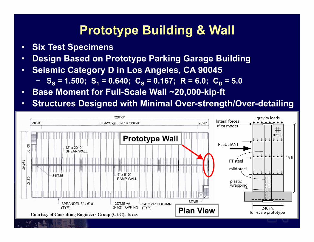
• Six Test Specimens • Design Based on Prototype Parking Garage Building• Seismic Category D in Los Angeles, CA 90045
− SS = 1.500; S1 = 0.640; CS = 0.167; R = 6.0; CD = 5.0• Base Moment for Full-Scale Wall ~20,000-kip-ft• Structures Designed with Minimal Over-strength/Over-detailing
Prototype Building & Wall
Prototype Wall
Plan View 5

• 0.4 Scaled Test with Two Wall Panels• Specimen Design Parameters:
∆wd = 0.54% - 0.87%; ∆wm = 2.30%(Hw / Lw = 2.25)
Upper Panel(2nd - 4th Stories)
Foundation
Base Panel(1st Story)
Gravity Load Jack
6
ACI Required Drift History
∆wm = Validation-Level Drift=2.3%
Validation-Level Drift
Experimental Program
Panel Perforation
Applied Lateral Load
∆wm = 0.90% ≤ 0.80(Hw / Lw) + 0.5 ≤ 3.0%
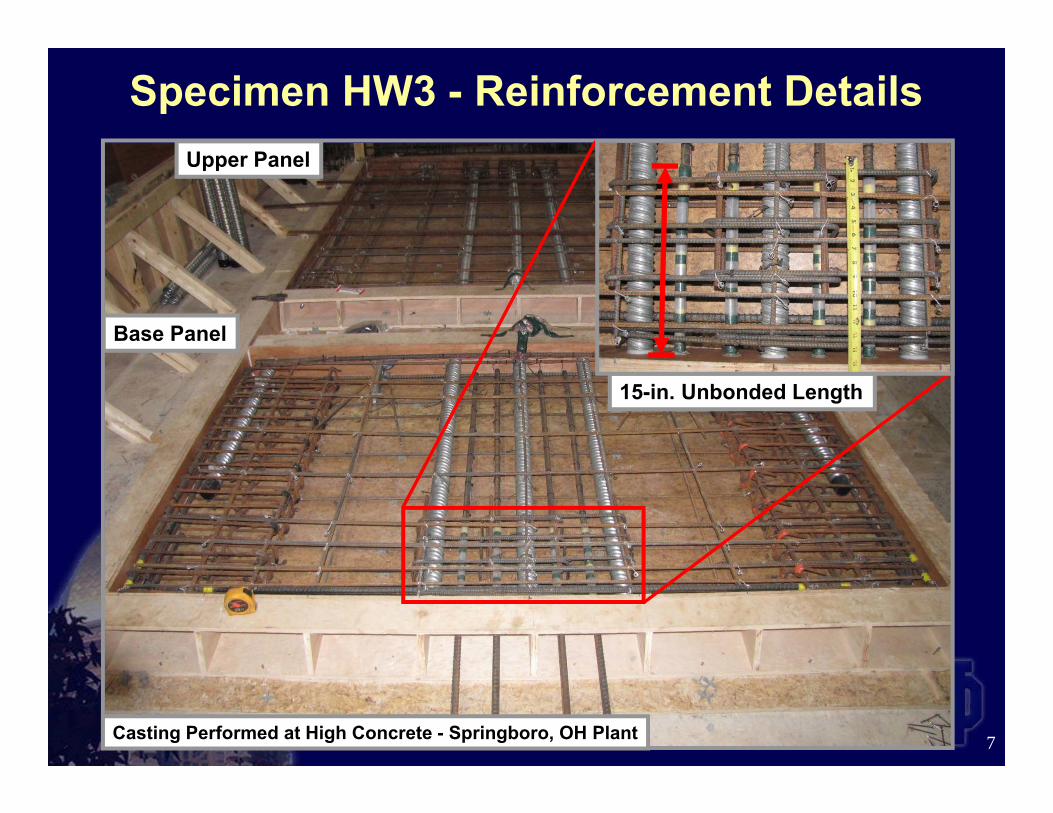
Upper Panel
Base Panel
15-in. Unbonded Length
Specimen HW3 - Reinforcement Details
7Casting Performed at High Concrete - Springboro, OH Plant

Base Panel
Block-Out for Panel Perforation
Additional ReinforcementAround Panel Perforations
8
Specimen HW4 - Reinforcement Details

9
Hysteretic Behavior of Validated Hybrid Walls
HW3: Solid Wall HW4: Perforated Wall
10
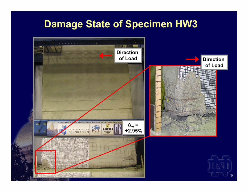
∆w = +2.95%
Direction of Load
Damage State of Specimen HW3
Direction of Load

Outline
• Introduction & Objectives• Experimental Program• Seismic Design Approach• Analytical Investigation• Summary and Acknowledgements
11

12
Performance Objectives• Design-Level Drift
- Gap Opening at Base Joint- Yielding of E.D. Bars- PT Steel Linear-Elastic- Minor Concrete Cracking- Cover Concrete on
Verge of Spalling
• Maximum-Level Drift- No Significant Gap Opening
at Upper Joints - No Significant Residual Vertical
Wall Uplift Upon Unloading- No Significant Slip at Joints- No Fracture of E.D. Bars- No Fracture or Significant
Yielding of PT Steel- Confined Core Concrete on
Verge of Crushing
Idealized Wall Behavior
• Iterative Process to Determine:• E.D. Steel Area• PT Steel Area
• Fundamental Design Principles for Partially-Prestressed RC Structures
13
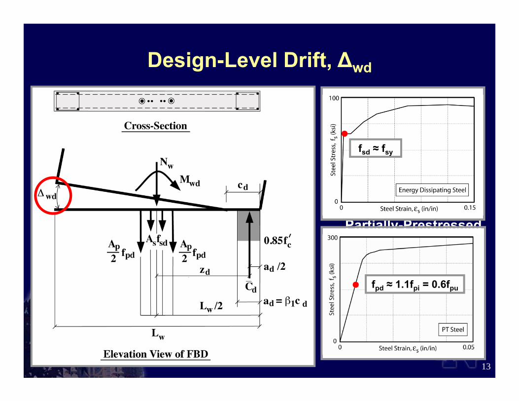
Design-Level Drift, ∆wd
fpd ≈ 1.1fpi = 0.6fpu
fsd ≈ fsy
• Determine Probable Base Moment Strength
• Design Confinement Steel at the Toes
• Satisfy Maximum PT and E.D. Steel Strain Limits to Prevent Fracture
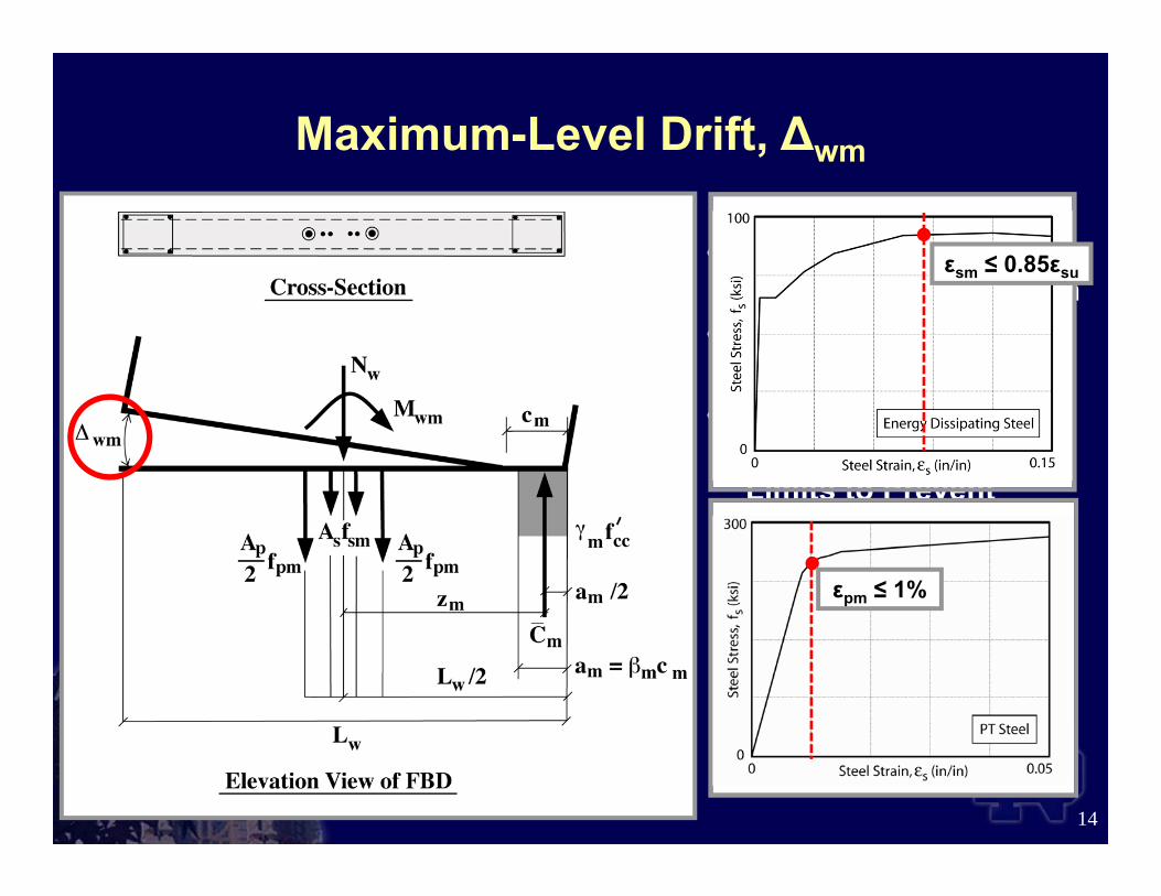
14
Maximum-Level Drift, ∆wm
εpm ≤ 1%
εsm ≤ 0.85εsu
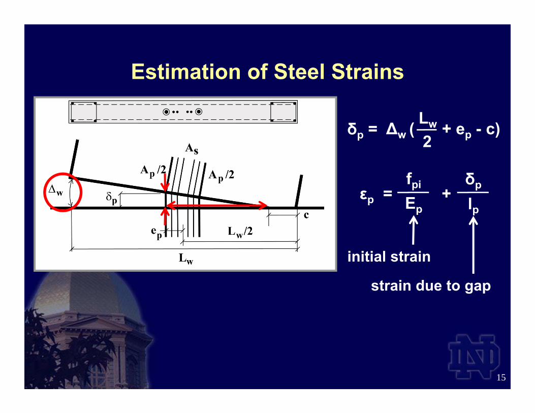
∆w ( + ep - c)δp = Lw
2
15
Estimation of Steel Strains
δp
lpεp = +
fpi
Ep
initial strain
strain due to gap

Outline
• Introduction & Objectives• Experimental Program• Seismic Design Approach• Analytical Investigation• Summary and Acknowledgements
16

• DRAIN-2DX Program • Concrete Wall Panels
• Fiber Beam-Column Elements
• Unbonded PT Steel• Truss Elements
• E.D. Steel• Truss Elements
Fiber Element Model
17

Lateral Load versus Deflection Behavior
18
Measured Analytical

19
Measured Analytical
Gap Opening DisplacementsGap Opening

PT Steel Stresses
20
Measured Analytical

21
MCE Level Dynamic Peak Drift Demands
• ∆wm = 2.30% Reasonable for Validation-Level Drift
Unscaled MCE Scaled MCE
22
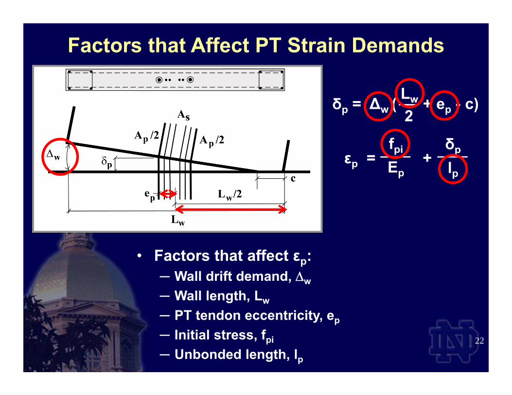
Factors that Affect PT Strain Demands
δp
lpεp = +
fpi
Ep
• Factors that affect εp:─ Wall drift demand, w
─ Wall length, Lw
─ PT tendon eccentricity, ep
─ Initial stress, fpi
─ Unbonded length, lp
∆w ( + ep - c)δp = Lw
2
23
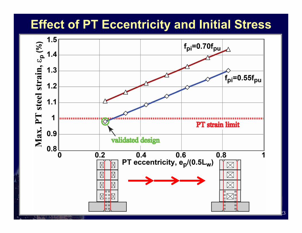
Effect of PT Eccentricity and Initial Stress

• Tested Six 0.4-Scaled Specimens- Developed Validation Evidence for Hybrid Walls
as Special RC Shear Walls in Seismic Regions
24
Summary
HW4HW3

Implications for Unbonded Post-Tensioning• Large PT Strain Demands Under Extreme Loading• Strand-Anchorage Systems up to 2% Strain Capacity
May be Needed for Seismic Regions
25

• Sponsors- The Charles Pankow Foundation- PCI Research & Development Committee- High Concrete Group, LLC- The Consulting Engineers Group – Texas- PCI Central Region - University of Notre Dame
• Advisory Panel- Walt Korkosz - The Consulting Engineers Group, Inc.- Ken Baur - High Concrete Group, LLC- Neil Hawkins - Univ. of Illinois Urbana-Champaign- S.K. Ghosh - S.K. Ghosh Associates, Inc.- Dave Dieter - Mid-State Precast, LP
• Industry Support- Dayton Superior Corp.- ECCO Manufacturing- Enerpac Precision
SURE-LOCK
- Essve Tech, Inc. - Prestress Supply, Inc.- Sumiden Wire Products Corp.- Summit Engineered Products- Ambassador Steel Corp. 26
Acknowledgements

WEBSITE: