Hybrid Micro-machining Processes: A Review · machining operations on one machine in order to...
86
1 Hybrid Micro-machining Processes: A Review Saeed Zare Chavoshi, Xichun Luo* Centre for Precision Manufacturing, Department of Design, Manufacture and Engineering Management, University of Strathclyde, Glasgow, G1 1XJ, UK * [email protected] Abstract Micro-machining has attracted great attention as micro-components/products such as micro- displays, micro-sensors, micro-batteries, etc. are becoming established in all major areas of our daily life and can already been found across the broad spectrum of application areas especially in sectors such as automotive, aerospace, photonics, renewable energy and medical instruments. These micro-components/products are usually made of multi-materials (may include hard-to-machine materials) and possess complex shaped micro-structures but demand sub-micron machining accuracy. A number of micro-machining processes is therefore, needed to deliver such components/products. The paper reviews recent development of hybrid micro-machining processes which involve integration of various micro-machining processes with the purpose of improving machinability, geometrical accuracy, tool life, surface integrity, machining rate and reducing the process forces. Hybrid micro-machining processes are classified in two major categories namely, assisted and combined hybrid micro- machining techniques. The machining capability, advantages and disadvantages of the state- of-the-art hybrid micro-machining processes are characterized and assessed. Some case studies on integration of hybrid micro-machining with other micro-machining and assisted
Transcript of Hybrid Micro-machining Processes: A Review · machining operations on one machine in order to...

1
Hybrid Micro-machining Processes: A Review
Saeed Zare Chavoshi, Xichun Luo*
Centre for Precision Manufacturing, Department of Design, Manufacture and Engineering
Management, University of Strathclyde, Glasgow, G1 1XJ, UK
Abstract
Micro-machining has attracted great attention as micro-components/products such as micro-
displays, micro-sensors, micro-batteries, etc. are becoming established in all major areas of
our daily life and can already been found across the broad spectrum of application areas
especially in sectors such as automotive, aerospace, photonics, renewable energy and medical
instruments. These micro-components/products are usually made of multi-materials (may
include hard-to-machine materials) and possess complex shaped micro-structures but demand
sub-micron machining accuracy. A number of micro-machining processes is therefore,
needed to deliver such components/products. The paper reviews recent development of
hybrid micro-machining processes which involve integration of various micro-machining
processes with the purpose of improving machinability, geometrical accuracy, tool life,
surface integrity, machining rate and reducing the process forces. Hybrid micro-machining
processes are classified in two major categories namely, assisted and combined hybrid micro-
machining techniques. The machining capability, advantages and disadvantages of the state-
of-the-art hybrid micro-machining processes are characterized and assessed. Some case
studies on integration of hybrid micro-machining with other micro-machining and assisted
2
techniques are also introduced. Possible future efforts and developments in the field of hybrid
micro-machining processes are also discussed.
Keywords: Micro-component; Hybrid micro-machining; Process integration
Nomenclature
BUE built-up edge
CCM conventional cutting method
CIRP college international pour la recherche en productique
CUSM chemical-assisted ultrasonic machining
DC direct current
ECAM electrochemical arc machining
ECDM electrochemical discharge machining
ECM electrochemical machining
ECSM electrochemical spark machining
EDM electrodischarge machining
EMM electrochemical micro-machining
ERP electrorheological fluid-assisted polishing
EVC elliptical vibration cutting

3
EWR electrode wear rate
FEM finite element method
FTS fast tool servo
HAZ heat-affected zone
HF hydrofluoric
HFDG high frequency dither grinding
JECM jet electrochemical machining
LAJECM laser-assisted jet electrochemical machining
LAMM laser-assisted micro-milling
MRR material removal rate
PET polyethylene terephthalate
PMMA polymethyl methacrylate
RC resistor-capacitor
R-MEDM reverse micro-electrical discharge machining
ROC radial overcut
SACE spark-assisted chemical engraving
SEDCM simultaneous micro-EDM and micro-ECM
SEM scanning electron microscope
TBC thermal barrier coating

4
USM ultrasonic machining
UV ultraviolet
WC tungsten carbide
WEDG wire electrodischarge grinding
WEDM wire electrodischarge machining
1. Introduction
In recent years, the demand for micro-components/products has increased at a rapid pace in
various areas such as electronics, bio-medical, aviation, energy and optical industries [1]. The
characteristics of these micro-components/products are: 1) size of functional features in
micrometre level, from few micrometres up to 100 micrometres; 2) high precision tolerances,
typically better than 1 micrometre; 3) good surface finish, in general surface roughness Ra
smaller than half micrometre; 4) 3D or complicated structures; 5) use of a variety of materials
such as ceramics, hard steels, titanium alloys, etc. [2]. Many surface or bulk micro-machining
processes based on lithography, chemical or plasma etching, printing, moulding, transfer and
assembly techniques have been proposed for micro/nano-device batch fabrication [3-4]. They
can provide components with small feature sizes in inorganic and organic materials and even
3D shapes. Micro-machining techniques reviewed in this paper are fully complementary
techniques able to provide complex geometries in a large range of materials with a high
relative accuracy. They constitute a promising technology for bridging the gap between
macro and micro/nano domains [5-7].

5
Although traditional stand-alone (single function) machine tools have been used as a major
means to fabricate micro-components/products, it still remains a big issue in the
predictability, producibility and productivity of fabrication of micro-components/products,
especially for those with complex surface forms/shapes [8]. In recent years some
multifunctional machine tools have been developed to implement several mechanical
machining operations on one machine in order to rapidly and economically fabricate those
components/products while research has also been drawn on the development of hybrid
machines which will integrate conventional and non-conventional machining processes on
them [9]. Some hybrid micro-machining processes have been approved to be able to improve
machinability of hard-to-machine materials, tool life, geometrical accuracy, surface integrity
and machining efficiency.
There is no exact description for hybrid machining processes [10]. From time to time a
number of definitions for hybrid machining processes have been proposed by researchers like
Rajurkar et al. [11], Kozak and Rajurkar [12], Aspinwall et al. [13], Curtis et al. [14],
Lauwers [15] etc.. Aspinwall et al. [13] explained that the combination of machining
operations can be considered either in terms of a hybrid machining method, by which two or
more machining processes are applied independently on a single machine, or in terms of an
assisted machining approach, by which two or more processes are utilised simultaneously.
She and Hung [16] stated that hybrid machines can perform different operations such as
mechanical milling and turning at one place. Curtis et al. [14] provided a narrow definition,
stating that only a method, where two or more material removal processes work
simultaneously can be termed as ‘hybrid’. In 2014, the College International Pour la
Recherche en Productique (CIRP) collaborative working group on hybrid processes put
forward the following definition: hybrid machining processes are based on the simultaneous
and controlled interaction of machining mechanisms and/or energy sources/tools having a

6
significant effect on the process performance. The wording “simultaneous and controlled
interaction” means that the processes/energy sources should interact more or less in the same
processing zone and at the same time [17]. Accordingly, in this paper, hybrid micro-
machining processes are classified as assisted and combined hybrid micro-machining
processes (as shown in Fig. 1). The major part of the paper (sections 2 and 3) provides a
comprehensive review on the state-of-the-art hybrid micro-machining researches conducted
within the above categories. Section 4 discusses the case studies on integration of hybrid
micro-machining with other micro-machining and assisted techniques. Future research
opportunities in hybrid micro-machining processes are discussed in section 5. The paper will
conclude with a brief review on the discussed subjects. In the paper micro-machining
processes refer to mask-less direct material removal processes. It should be noted here that
hybrid surface and bulk micro-machining based on coating, lithography, moulding, etching
and assembly of films and substrates are other approaches that will not be covered in the
paper.

7
Fig. 1. Classification of hybrid micro-machining processes
2. Assisted hybrid micro-machining processes
For assisted hybrid micro-machining, the major machining process is superimposed with
input from one or several types of energy such as ultrasonic vibration, laser, fluid, magnetic
field etc. so as to improve the constituent micro-machining process [15, 18].
Hybrid Micro-
machining
Assisted Hybrid
Micro-machining
Combined Hybrid
Micro-machining
Vibration-Assisted
Laser-Assisted
Fluid-Assisted
Magnetic field-
Assisted
External electric
field-Assisted
…
ECDM
SEDCM
JECM-LD
ECM-Grinding
EDM- ER fluid-
assisted polishing
…

8
2.1. Vibration assisted micro-machining
Vibration-assisted micro-machining combines precision micro-machining with small-
amplitude tool, workpiece or work fluid vibrations. This approach has been applied to a
number of processes from micro-milling to micro-electrochemical discharge machining
(ECDM). During vibration-assisted micro-cutting, the cutting tool loses contact with the
chips on specified amplitude, resulting in decreasing of machining forces and improving tool
life and surface finish [19]. However, it may result in surface cracks due to the hammering of
the tool [15].
Vibration also finds its applications in other non-cutting processes. For example, in
ultrasonic-assisted electrodischarge micro-machining (EDM), vibration can be applied
between the tool and workpiece in order to increase the flushing efficiency, resulting in a
higher material removal rate. If process parameters are selected carefully, smooth surfaces
can be obtained. The vibration supports the removal of re-solidified debris and hence results
in a smaller heat-affected zone (HAZ), lower thermal stresses and fewer cracks [15]. Besides,
work fluid vibration heightens circulation of the debris and increases the machining rate,
surface finish and accuracy in processes such as micro-EDM and electrochemical machining
(ECM). A summary of research work carried out in this area is listed in Table 1.
Table 1. Summary of the vibration-assisted micro-machining processes
Vibration-assisted micro-
machining process
Work material Primary characteristic
Vibration-assisted milling H13 [22], Al 6061 [51-52], AL6061-T6 [49] Achieved surface roughness (Ra) for
AL6061 is 0.105 µm [52]

9
Nearly 22% reduction in tool life [49]
Vibration-assisted grooving Glass [25,32], Al2024 [26], Plexiglas [26],
Brass [28], Si wafer [33], Pure nickel [27],
Nickel alloy [27], Mold steels [27], Al6061
[27], Copper [29-30]
Better micro-groove shape [25,27]
Reduction in average size of chippings
[32]
Vibration-assisted engraving Aluminium alloy [32], Piezoceramic
material [32], Stainless steel [32]
60% reduction in cutting force [32]
Vibration-assisted grinding Ultra-fine grain cemented carbide [24] 10-20 % smaller diameter and 50 %
higher aspect ratio when fabricating of
micro-tools [24]
Vibration-assisted drilling Single crystalline silicon [23], Glass [53],
AA2017 [54], SUS304 [54], Al6061-T6
[50], SS41 [50]
60-70% reduction in cutting force [53]
Vibration-assisted polishing Binderless tungsten carbide [36-38] Achieved surface roughnesses are 7 nm
Ry [36], 8 nm Rz [37], 12 nm Rz [38]
Vibration-assisted lapping Silicon [34], Ti-6Al-4V [55] Achieved surface roughness (Ra) for
Silicon is 10 nm [34]
Vibration-assisted EDM Stainless steel [56, 64], Copper [56], A2 tool
steel [65], 1.5920 steel [63], WC of Grade
MG18 [57-61], Steel [62], X210Cr12 (D3
DIN) [42], SUS304 [72, 73-74],
Polycrystalline diamond [40], Nitinol [41],
Hymu 80 [62], Brass [39]
Up to 66.48% increasing of material
removal rate [40]
Increasing the machining efficiency by
more than 60 times [41]
Vibration-assisted EDM milling Red copper [66] 6.5 times improvement in machining
efficiency [66]

10
Vibration-assisted reverse EDM Ti-6Al-4V [44] Improvement in process stability [44]
Vibration-assisted WEDM Ti-6Al-4V [67], Tungsten carbide [43] 2.5 times increase in machining
efficiency [67]
Vibration-assisted ECM Copper [46], SUS304 [47], Tool steel NC6
[45], SS321 [68]
Achieved surface roughness (Ra) for
SUS304 is 2.1 nm [47]
Vibration-assisted laser
machining
ASTM W110 [69], Nitinol [70], Copper [75-
76]
Smoother surface [70]
2.1.1. Tool vibration-assisted micro-machining
In tool vibration-assisted micro-machining, a piezoelectric transducer, booster and horn are
usually applied to generate tool vibration. Electrical impulses are fed to a piezoelectric
transducer and transformed into mechanical vibrations of ultrasonic frequency thanks to the
piezoelectric effect. The vibration amplitude is then amplified by the booster and the horn
and transmitted to the tool attached to the horn [20-21]. The primary focus in tool vibration-
assisted micro-machining is on the study of the vibration effect on the tool wear, surface
quality, micro-cutting forces, material removal rate (MRR), machining time, micro-hole
aspect ratio and chipping. This has been performed by fabrication of simple micro-structures
like micro-grooves and holes on different materials with main purpose of investigation of the
processing parameters.
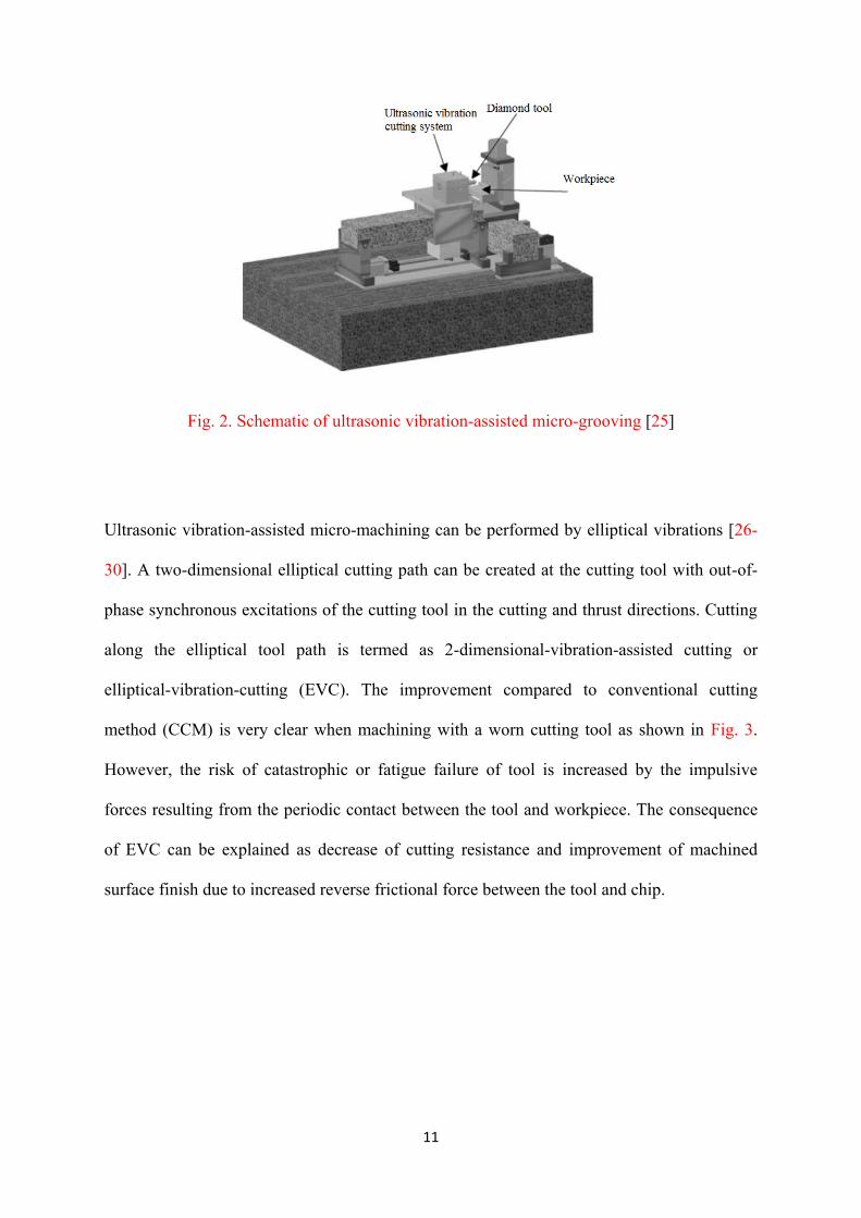
Ultrasonic vibration-assisted micro-milling, grinding, drilling and grooving are found to have
the ability to produce better geometrical shape, surface quality, lower tool wear and chipping
[22-25]. Fig. 2 shows a machining system of the ultrasonic vibration-assisted micro-grooving
used for grooving of glass and planar lightwave circuits.
11
Fig. 2. Schematic of ultrasonic vibration-assisted micro-grooving [25]
Ultrasonic vibration-assisted micro-machining can be performed by elliptical vibrations [26-
30]. A two-dimensional elliptical cutting path can be created at the cutting tool with out-of-
phase synchronous excitations of the cutting tool in the cutting and thrust directions. Cutting
along the elliptical tool path is termed as 2-dimensional-vibration-assisted cutting or
elliptical-vibration-cutting (EVC). The improvement compared to conventional cutting
method (CCM) is very clear when machining with a worn cutting tool as shown in Fig. 3.
However, the risk of catastrophic or fatigue failure of tool is increased by the impulsive
forces resulting from the periodic contact between the tool and workpiece. The consequence
of EVC can be explained as decrease of cutting resistance and improvement of machined
surface finish due to increased reverse frictional force between the tool and chip.

12
Fig. 3. Comparisons of pyramid patterns machined by CCM and EVC (workpiece material:
Inconel 600) [27]
Ultrasonic elliptical vibration transducer can be integrated with fast tool servo (FTS) to
realize complex shape machined surfaces while achieving reduced cutting force and
prolonged tool life [31]. 60% reduction of cutting force is observed in the cutting process
with this new vibration device. Two dimensional error curve of micro-V-groove machined on
aluminium alloy (shown in Fig. 4) indicates that there is a significant degradation of the
machined shape with a large increase of the error when micro-V-grooving with vibration
assistance.
(a) Machined without vibration (b) Machined with vibration

13
Fig. 4. Two-dimensional error curve of micro-V-groove surface on aluminium alloy
workpiece [31]
Ultrasonic-assisted micro-lapping has the ability to make hole arrays, trenches, rings,
polygons, asterisks, spirals, arbitrary curves, etc., on silicon with feature sizes ranging from
50 to 500 µm, and aspect ratios of from 1 to 5 [34]. However, it is claimed that the currently
available knowledge on ultrasonic-assisted micro-lapping is still insufficient especially on
tool wear, subsurface damage control, and relatively coarse surface roughness [35].
In polishing of micro-aspheric molds, an ultrasonic vibration assisted polishing tool is useful
to finish the surface. A small polishing tool (shown in Fig. 5) is mounted on a three-axis or
five-axis controlled work table, and vibrated at an ultrasonic frequency by piezoelectric
actuators, as illustrated in Fig. 6. Application of this polishing machine on tungsten carbide
results in lowering surface roughness to 8 nm Rz [36-38].
Fig. 5. View of polishing tool [36]

14
Fig. 6. Illustration of ultrasonic two-axis vibration-assisted polishing [37]
Adding ultrasonic vibration to non-traditional micro-machining processes allows an
improvement in machining performance. The combination of tool vibration and EDM has
profound effects on reduction of machining time and increasing machining stability without
increasing surface roughness and tool electrode wear [39-41]. It is found that the
perpendicular vibration has a shorter machining time than the parallel vibration in vibration-
assisted micro-EDM process [39]. Based on both experimental data and finite element
method (FEM) modelling results, It is confirmed that when using longer pulse time (25 µs)
the advantage of tool ultrasonic vibration-aided micro-EDM of X210Cr12 (D3 DIN) is more
apparent in terms of machining rate. But longer pulse time than 25 µs is not appropriate at
usual 20 kHz frequency since higher pulse energy will result in low machining accuracy and
surface quality [42]. In wire electrical discharge grinding (WEDG), by adding vibration to the
wire electrode directly, the surface integrity of tungsten carbide can be improved which is
superior to that by vibrating dielectric fluid or without ultrasonic assistance [43].
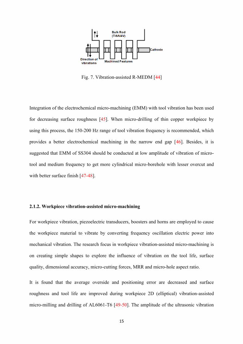
Fig. 7 shows a schematic illustration of vibration-assisted reverse micro-electrical discharge
machining (R-MEDM) which is used to create micro-pillars of 40-50 μm diameter. It is
claimed that a surface texture comprising of any cross-section micro-pillar array on the
metallic surfaces can be produced deterministically only by the R-MEDM process [44].
15
Fig. 7. Vibration-assisted R-MEDM [44]
Integration of the electrochemical micro-machining (EMM) with tool vibration has been used
for decreasing surface roughness [45]. When micro-drilling of thin copper workpiece by
using this process, the 150-200 Hz range of tool vibration frequency is recommended, which
provides a better electrochemical machining in the narrow end gap [46]. Besides, it is
suggested that EMM of SS304 should be conducted at low amplitude of vibration of micro-
tool and medium frequency to get more cylindrical micro-borehole with lesser overcut and
with better surface finish [47-48].
2.1.2. Workpiece vibration-assisted micro-machining
For workpiece vibration, piezoelectric transducers, boosters and horns are employed to cause
the workpiece material to vibrate by converting frequency oscillation electric power into
mechanical vibration. The research focus in workpiece vibration-assisted micro-machining is
on creating simple shapes to explore the influence of vibration on the tool life, surface
quality, dimensional accuracy, micro-cutting forces, MRR and micro-hole aspect ratio.
It is found that the average overside and positioning error are decreased and surface
roughness and tool life are improved during workpiece 2D (elliptical) vibration-assisted
micro-milling and drilling of AL6061-T6 [49-50]. The amplitude of the ultrasonic vibration

16
is an important parameter that can be optimized to achieve good surface roughness in this
process [51]. Reduction in force and increase of tool life, machining rate and machinable
depth are observed during workpiece vibration-assisted micro-drilling of glass [53], AA2017
(duralumin) and SUS304 [54]. This reduction in force can be achieved by 60-70% [53]. To
produce high precision micro-holes, workpiece vibration-assisted micro-lapping (as
illustrated in Fig. 8) is employed in order to improve the surface roughness and the roundness
of micro-holes [55].
Fig. 8. Using the stepped circular tool to manufacture the micro-hole in the vibration-assisted
micro-lapping process [55]
Workpiece vibration-assisted micro-EDM has been successfully performed by different
researchers. In the experiments carried out by Gao and Liu [56] ultrasonic vibration actuator
was adhered to the workpiece in micro-EDM, which led to eight times efficiency
improvement. Fig. 9 shows the experimental apparatus used by Gao and Liu [56].

17
Fig. 9. The combined apparatus of ultrasonic and micro-EDM [56]
It is revealed that there is a significant improvement in dimensional accuracy, surface quality
and MRR with substantial reduction of EDM gap, machining time and electrode wear rate
(EWR) during drilling deep micro-holes by means of workpiece vibration-assisted micro-
EDM. The experimental results also disclose that the low frequency vibration is more
effective at the low discharge energy level, thus making it more suitable for micro-EDM [57-
61]. Other studies employing workpiece vibration-assisted micro-EDM have been reported
[62-65]. Fig. 10 shows the SEM (scanning electron microscope) photographs of a machined
3D micro-structure by using workpiece vibration-assisted servo scanning 3D micro-EDM
[66].
Fig. 10. Machined 3D micro-structures by workpiece vibration-assisted servo scanning 3D
micro-EDM (workpiece material: Red copper) [66]

18
As identified by Hoang and Yang [67], greater improvement can be achieved when the
vibration is applied to the workpiece rather than to the wire in micro-wire electrodischarge
machining (WEDM) of Ti-6Al-4V. With vibration applied to the workpiece, the machining
efficiency can be increased by 2.5 times of that without vibration and 1.5 times compared to
the case when vibration is applied to the wire.
Applying vibration to the workpiece during laser micro-machining would deactivate the
agglomeration of nanoparticles and prevent the surface oxidation and the formation of recast
layer. Fig. 11 depicts the concept of this process. As a result, the surface roughness of a
machined surface could be more improved in the ultrasonic vibration-assisted laser micro-
machining than that in the case without vibration assistance [69-70].
Fig. 11. Concept of laser ablation processes by (a) conventional method and
(b) ultrasonic-applied method [69]
19
2.1.3. Work fluid vibration-assisted micro-machining
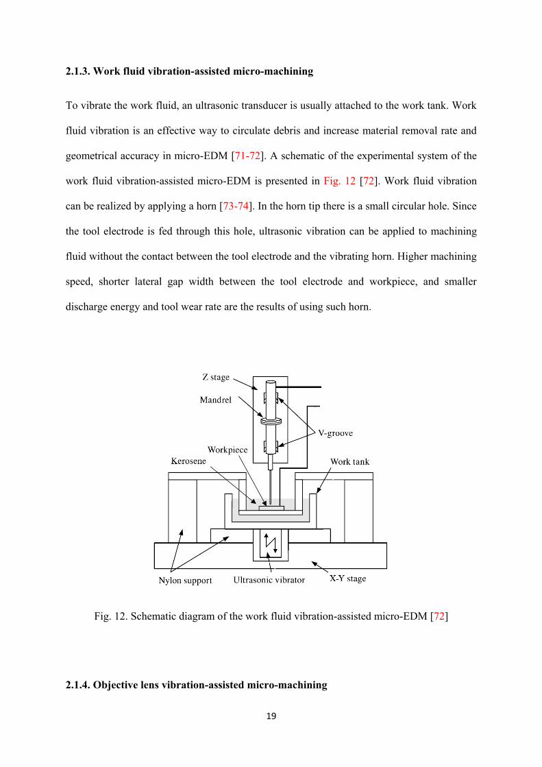
To vibrate the work fluid, an ultrasonic transducer is usually attached to the work tank. Work
fluid vibration is an effective way to circulate debris and increase material removal rate and
geometrical accuracy in micro-EDM [71-72]. A schematic of the experimental system of the
work fluid vibration-assisted micro-EDM is presented in Fig. 12 [72]. Work fluid vibration
can be realized by applying a horn [73-74]. In the horn tip there is a small circular hole. Since
the tool electrode is fed through this hole, ultrasonic vibration can be applied to machining
fluid without the contact between the tool electrode and the vibrating horn. Higher machining
speed, shorter lateral gap width between the tool electrode and workpiece, and smaller
discharge energy and tool wear rate are the results of using such horn.
Fig. 12. Schematic diagram of the work fluid vibration-assisted micro-EDM [72]
2.1.4. Objective lens vibration-assisted micro-machining
20
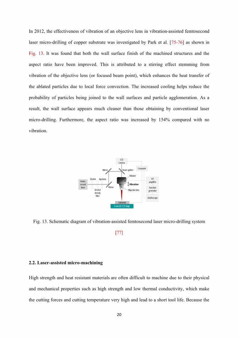
In 2012, the effectiveness of vibration of an objective lens in vibration-assisted femtosecond
laser micro-drilling of copper substrate was investigated by Park et al. [75-76] as shown in
Fig. 13. It was found that both the wall surface finish of the machined structures and the
aspect ratio have been improved. This is attributed to a stirring effect stemming from
vibration of the objective lens (or focused beam point), which enhances the heat transfer of
the ablated particles due to local force convection. The increased cooling helps reduce the
probability of particles being joined to the wall surfaces and particle agglomeration. As a
result, the wall surface appears much cleaner than those obtaining by conventional laser
micro-drilling. Furthermore, the aspect ratio was increased by 154% compared with no
vibration.
Fig. 13. Schematic diagram of vibration-assisted femtosecond laser micro-drilling system
[77]
2.2. Laser-assisted micro-machining
High strength and heat resistant materials are often difficult to machine due to their physical
and mechanical properties such as high strength and low thermal conductivity, which make
the cutting forces and cutting temperature very high and lead to a short tool life. Because the

21
flow stress and strain hardening rate of materials normally decrease with the increase of
temperature due to thermal softening, thermal-assisted machining becomes a possibility when
machining the hard-to-machine materials (see Fig. 14) [78]. Table 2 gives an overview of the
performed studies on the laser-assisted micro-machining processes. The major work on laser-
assisted micro-machining is to study some parameters such as surface roughness and micro-
machining forces by manufacturing simple micro-grooves and then to compare with those
obtained by conventional micro-machining.
Fig. 14. Mechanical strength as a function of temperature [17]
Table 2 Overview of the studies on the laser-assisted micro-machining
Laser-assisted micro-
machining process
Work material Primary characteristic
Laser-assisted milling H13 [79-81], A2 tool
steel [82-86], Ti-6Al-4V
[88-91], Inconel 718
17% reduction in mean thrust force [79-81]
69% reduction in peak resultant force [88-91]

22
[88], AISI 422 [88], AISI
D2 [89-91]
Improvement in accuracy of groove depth [79-81]
Increase of material removal rates up to six times [88-91]
Achieved surface roughness (Sa) for H13 is 0.65 µm [79-
81]
Achieved surface roughness (Ra ) for A2 is nearly 0.1
µm [83-86]
Laser-assisted grinding Reaction-sintered silicon
nitride [83-85], Si3N4
[92], Al2O3 [92]
Up to 43% reduction in average grinding forces [83-85]
Achieved surface roughness (Ra) for Si3N4 is 112.85 nm
[92]
Laser-assisted scratching 4H-SiC [82] Greater than 50% reduction in hardness [82]
Laser-assisted jet ECM Aluminium alloy,
Titanium alloy, Hastelloy
and, Stainless steel
[93-96]
Up to 78%. reduction in hole taper
Up to 46% increase in material removal rate
[93-96]
Laser-assisted water jet
machining
Single crystalline silicon
[97-98]
Near free of HAZ and high material removal rate [97-98]
2.2.1. Laser-assisted micro-milling/grinding
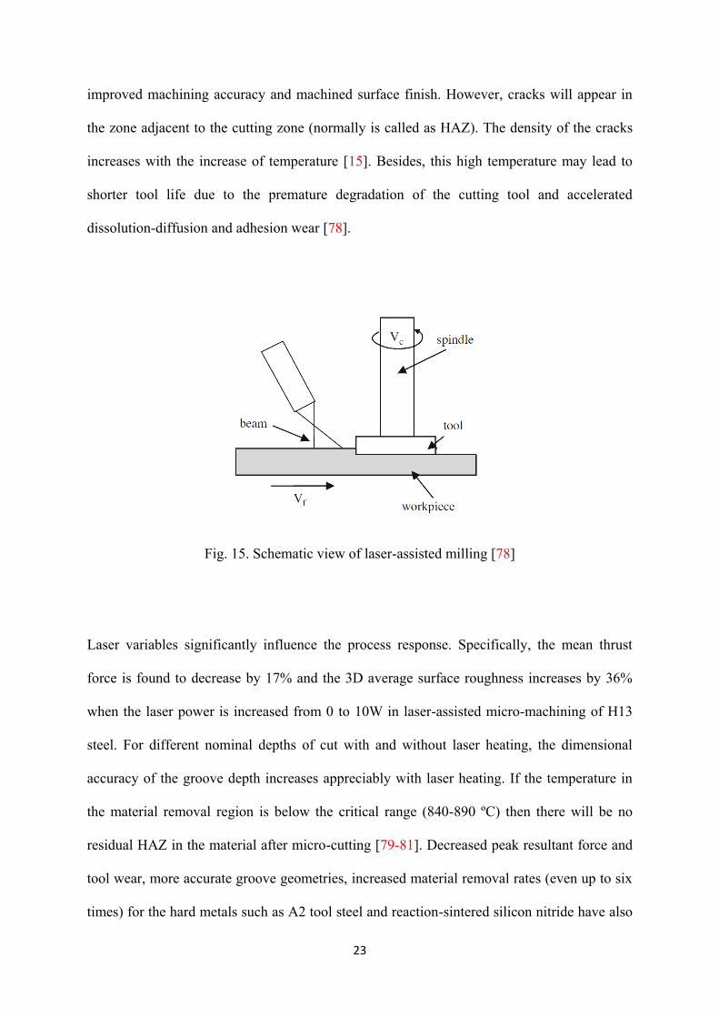
During laser-assisted micro-milling/grinding, workpiece is heated by a low power continuous
wave fibre laser and therefore is thermally softened. Laser provides intense localized heating
to the workpiece ahead of the cutting region. In this way the strength of the workpiece is
reduced and its machinability is improved. A schematic view of this process is illustrated in
Fig. 15. Laser-assisted micro-milling/grinding can result in decreased machining forces and
23
improved machining accuracy and machined surface finish. However, cracks will appear in
the zone adjacent to the cutting zone (normally is called as HAZ). The density of the cracks
increases with the increase of temperature [15]. Besides, this high temperature may lead to
shorter tool life due to the premature degradation of the cutting tool and accelerated
dissolution-diffusion and adhesion wear [78].
Fig. 15. Schematic view of laser-assisted milling [78]
Laser variables significantly influence the process response. Specifically, the mean thrust
force is found to decrease by 17% and the 3D average surface roughness increases by 36%
when the laser power is increased from 0 to 10W in laser-assisted micro-machining of H13
steel. For different nominal depths of cut with and without laser heating, the dimensional
accuracy of the groove depth increases appreciably with laser heating. If the temperature in
the material removal region is below the critical range (840-890 ºC) then there will be no
residual HAZ in the material after micro-cutting [79-81]. Decreased peak resultant force and
tool wear, more accurate groove geometries, increased material removal rates (even up to six
times) for the hard metals such as A2 tool steel and reaction-sintered silicon nitride have also

24
been reported in laser-assisted micro-machining [83-86]. However, in laser-assisted micro-
grinding of Si3N4 and Al2O3, grinding depth and force are almost the same as those in
conventional micro-grinding process [92]. The disadvantage of laser-assisted micro-
machining is that burr heights increase due to thermal softening of the workpiece. When a
tool diameter larger than the laser spot size is employed, the increase in burr height is much
smaller. When the laser spot size is larger than the tool diameter, the surface roughness is
found to increase due to increased thermal softening of the material [83].
There are a few research papers reporting on FEM modelling of laser-assisted micro-milling
(LAMM). This is partly because the available flow stress models are independent of the
length scale in the FE simulation and hence are not suitable for describing the significant size
effect in micro-cutting. In the researches, chip formation, flow stresses, temperature
distribution and velocity fields, which relate to the surface integrity analysis and built-up
edge (BUE) formation in micro-milling have been investigated [87-91].
2.2.2. Laser-assisted jet electrochemical micro-machining
In laser-assisted jet electrochemical machining (LAJECM), the main objective of employing
a laser is to improve the precision by better process localisation. Fig. 16 schematically
illustrates the principles and the mechanisms of LAJECM. The laser (power density
47.5W/mm2) is used only to thermally activate the outer surface layer. The predominant
mechanism of material removal is electrochemical dissolution and the role of the laser is to
assist and direct the electrochemical energy. The thermal energy of the laser transmitted to
the workpiece enhances the kinetics of electrochemical reactions and hence enables the
localisation of dissolution to a specific area. Laser-workpiece and laser-electrolyte interaction
cause higher material removal rate in axial rather than in the lateral direction and thereby

25
dimensional precision is improved. In addition to the localisation effect, the laser beam aids
in the removal of surface oxide layers that form on materials, thus enabling electrochemical
machining of materials such as titanium without recourse to hazardous electrolytes. Fig. 17
summarises the aspects laser localisation effects on jet ECM. The precision and productivity
improvements of LAJECM compared to jet electrochemical machining (JECM) have been
evidenced by experiments on aluminium alloy, titanium alloy, Hastelloy and stainless steel.
LAJECM can effectively facilitate material removal of 20, 25, 33, and 54% for Hasteloy,
titanium alloy, stainless steel and aluminium alloy, respectively. There is also a noticeable
improvement in the shape accuracy and slight decrease in surface roughness of the holes and
cavities produced due to more focused machining (the order of 20%). The measured
reduction in taper is of the order of 38, 40, 41, 65% for aluminium alloy, stainless steel,
Hasteloy and titanium alloy, respectively [93-96].

26
Fig. 16. Laser-assisted jet electrochemical machining process: (a) general view and (b) laser
localised machining area [95]
Fig. 17. Aspects of laser-electrolyte jet interaction in LAJECM (Redrawn from reference
[95])
2.2.3. Laser-assisted water jet micro-machining
The fundamental of this hybrid micro-machining technology is that, rather than achieving
material removal through melting and vaporizing the material by lasers, elemental material is
heated and softened by laser heating and removed by the expulsion of a high pressure
waterjet. This will not only reduce the temperature for material removal so as to reduce
thermal damages, but also requires less thermal energy input that allows the laser traverse
27
speed to be increased for a high cutting rate. Further, the cooling action by the waterjet
reduces thermal effect on the workpiece. It is believed that the pulsed laser heating and
waterjet expelling process also involves thermal shock effect on the work material, which
may result in micro-crack-induced material removal. However, it is believed that with a
suitable pressure setting of the waterjet, the contribution of this thermal shock to material
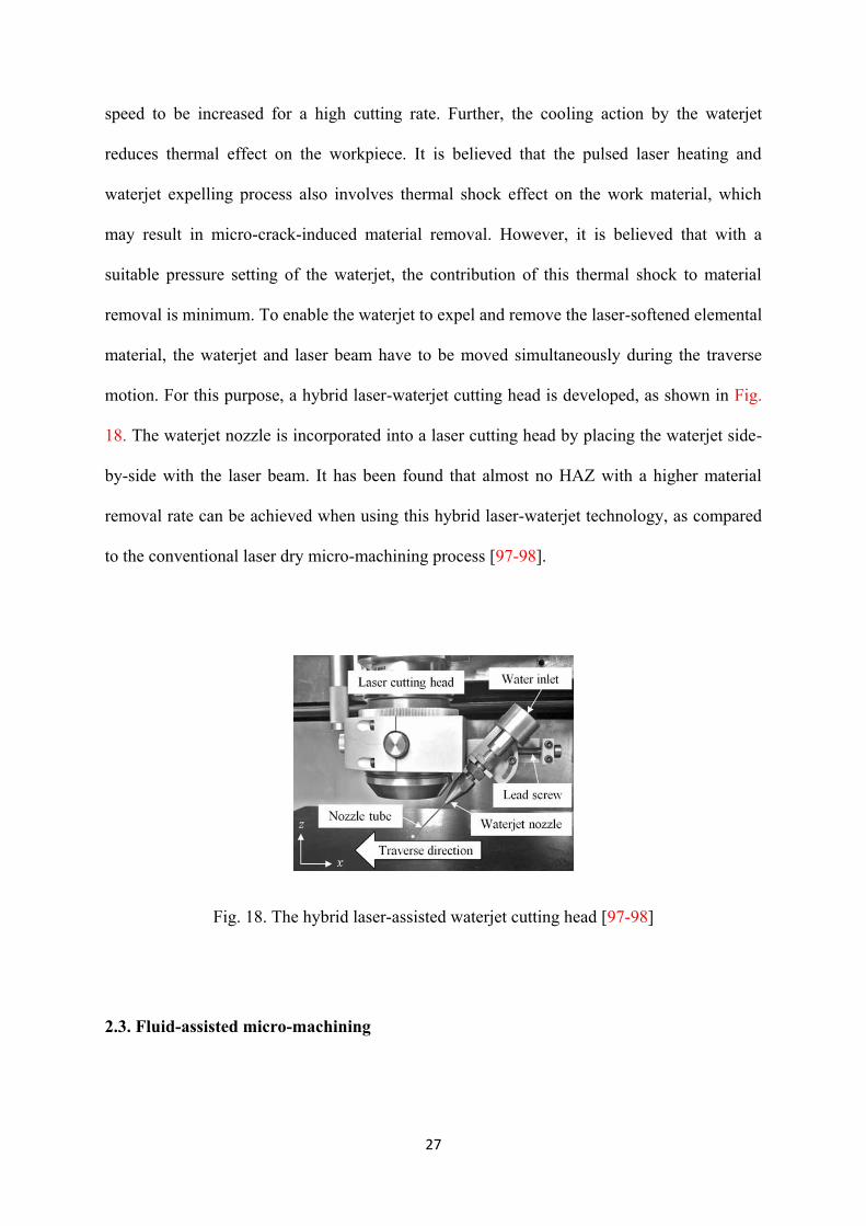
removal is minimum. To enable the waterjet to expel and remove the laser-softened elemental
material, the waterjet and laser beam have to be moved simultaneously during the traverse
motion. For this purpose, a hybrid laser-waterjet cutting head is developed, as shown in Fig.
18. The waterjet nozzle is incorporated into a laser cutting head by placing the waterjet side-
by-side with the laser beam. It has been found that almost no HAZ with a higher material
removal rate can be achieved when using this hybrid laser-waterjet technology, as compared
to the conventional laser dry micro-machining process [97-98].
Fig. 18. The hybrid laser-assisted waterjet cutting head [97-98]
2.3. Fluid-assisted micro-machining

28
This hybrid assisted micro-machining process includes applying water, gas, chemicals or
special fluids on the workpiece with the aim of increasing the process performance. Table 3
gives an overview of the micro-machining processes carried out with the assistance of
various fluids.
Table 3. Summary of the fluid-assisted micro-machining processes
Fluid-assisted micro-machining
process
Work material Primary characteristic
water-assisted laser machining Silicon [99], LCD glass
[101], alumina [104],
PET [104], PMMA [104]
Increase of material removal rates up to twice [99]
Improvement in surface quality [104]
No laser ablation enhancement for PET [104]
Reduction in micro-cracking and HAZ size [101]
Gas-assisted laser drilling Nimonic 263 coated with
a TBC [105]
Delamination-free drilled holes [105]
Methanol-assisted laser
machining
Single crystalline silicon
carbide [106]
Improvement in drilling quality [106]
Salt solution-assisted laser
machining
316 stainless steel [107] Up to 300% increase in material removal rate [107]
Chemical-assisted ultrasonic
machining
Glass [108] Up to 40% improvement in surface finish and material
removal rate [108]
Electrochemical-assisted
machining
304 stainless steel [109] Decrease cutting force [109]

29
Electrorheological fluid-assisted
ultrasonic machining
Quartz glass [112-114] Improvement in accuracy and efficiency [112-114]
2.3.1. Water-assisted micro-machining
It is possible to ablate micrometre range high aspect ratio holes in silicon, LCD glass and
alumina by water-assisted femtosecond and CO2 laser pulse ablation. By applying thin water
layer on the processed surface, holes can be drilled more efficiently and with less taper,
micro-cracks and HAZ than in air atmosphere. Furthermore, with water, the ablation rate is
about two times faster than without it. Reason for such improvements is the removal of the
ablation debris from the processing area during the drilling process. When there is no thin
water spray to collect and transport the debris away from the processing area, the ablation
debris is blocking the energy transition into the ablation process itself. Debris scatters and
absorbs the incoming pulses and therefore drilling is not so efficient. When water is used, it
removes debris continuously away from the holes and therefore drilling process is equally
efficient with following pulses. Scattering caused by debris is also inflicting the shape of the
hole [99-102]. The drawback is that the ablated surface is somewhat rough as a result of rapid
solidification of the molten material [103].
It has been reported that water can substantially improve the surface quality (topography,
bump, debris, etc.) in excimer laser ablation of Si and Al2O3. Moreover, it has been found
that laser ablation is enhanced at low laser fluences by water for polymethyl methacrylate
(PMMA) while no enhancement is achieved by water for polyethylene terephthalate (PET).
This striking difference suggests that the ablation mechanisms for the two polymer materials
are different to a large degree. If ablation of a polymer by a ultraviolet (UV) pulse occurs
entirely by the photochemical effect, the influence of liquid will be relatively insignificant,

30
compared with a photothermal process in which hydrodynamics of the ablation plume and
melt pool is important. Ablation of PET by a UV laser is largely dominated by a
photochemical process while that of PMMA is significantly affected by a photothermal
effect. The surface formed by excimer laser ablation of PET is smoother than PMMA, which
also corroborates the above notion regarding the ablation mechanism of the two polymers
[104]. Fig. 19 shows the schematic diagram of the laser ablation and experimental set-up of a
workpiece under water.
(a)
(b)
Fig. 19. Schematics of the water-assisted laser ablation setup [99, 104]

31
2.3.2. Gas-assisted micro-machining
Laser micro-drilling of cooling holes in certain parts of the aero-engine components involves
percussion or trepan drilling at acute angles to the surface. These parts are made of Nimonic
263 superalloy and often covered with plasma sprayed ceramic thermal barrier coatings
(TBC) to protect them from reaching excessive temperatures in hot engine environments.
Delamination of the TBC is the main problem of laser micro-drilling acute angled holes in
the coated components. In order to address this problem, a technique is proposed based on the
control of the melt flow trajectories and impact angle on the hole walls applying a secondary
gas jet. A schematic of this process is depicted in Fig. 20. An off-axis gas jet impinging near
the leading edge of the inclined hole during laser drilling process is introduced to control the
trajectories and impact speed of the melt on the TBC walls. The off-axis jet is impinged at
90° to the beam axis (α=90°). The co-axial and off-axis nozzle exit to workpiece off-set
distances are 8 and 4 mm, respectively. Oxygen for the co-axial and nitrogen for the off-axis
jets are used via 1.5 mm exit diameter converging nozzles. It has been demonstrated that a
less erosive melt ejection occurs at the hole entrance and consequently melt ejection-induced
TBC delamination was reduced or in some cases was completely prevented when micro-
drilling of 0.6 mm holes in TBC Nimonic 263 substrate material by using the technique.
However, some cracks were observed at the BC/substrate interfaces owing to the changes in
the melt and vapour flow introduced by secondary jet in the process. Nonetheless, these
cracks were diminutive in both lengths and width and represented a lesser risk of further
propagation [105].

32
Fig. 20. Concept of twin gas jet-assisted laser micro-drilling [105]
2.3.3. Chemical-assisted micro-machining
In laser micro-drilling, instead of water, methanol can be used as a solvent to produce micro-
holes with a relatively cleaner and smoother surface. The improvement of drilling quality can
be attributed to the relatively lower boiling temperature and better wettability of the solvent,
which enhance the effects of cooling (thermal damage free) and ablated particle cleaning
during laser micro-drilling. A thin-layer liquid film can easily modify the optical properties of
a surface. It can be explained that the reflective index of liquids (i.e., water and methanol) is
greater than that of air; the overall surface absorptivity increases as the liquid film is applied
on the surface. It is believed that plasma confinement is generated in a liquid environment at
a higher radiant exposure regime (i.e., 1>GW/cm2), consequently inducing higher
temperature, higher pressure, and higher density plasma (i.e., laser-induced plasma) at the Si
surface when the laser pulse irradiated the surface of the solid target through the liquid,
leading to more explosive removal of material. A methanol layer of 500 µm is suggested to
be used for the enhancement of laser ablation rate and quality in chemical-assisted laser
micro-drilling of single crystalline silicon carbide [106]. Salt solution can be also used so as
to improve the machining quality and material removal rate in laser micro-machining. HAZ

33
size and recast are significantly reduced for both laser milling and drilling of 316 stainless
steel material. Fig. 21 compares the HAZ of the holes machined in the salt solution and in air,
exhibiting much reduced heat affected area in the case of salt solution. More importantly, up
to 300% material removal rate increase is obtained compared that in air [107].
(a) (b)
Fig. 21. Comparison of holes drilled in a) air, and b) in salt solution (workpiece material: 316
stainless steel) [107]
A low concentration of hydrofluoric (HF) acid is added to the abrasive slurry in USM
(ultrasonic machining) in order to overcome the disadvantages of the conventional USM such
as a low material removal rate and surface quality. In the process of the USM, materials are
removed by micro-chipping or erosion with the abrasive particles. The tip of the tungsten
carbide (WC) tool vibrates at low amplitude (2-50 µm) and high frequency (20 kHz), which
transmits a high velocity to the fine abrasive grains between the tool and the surface of the
workpiece. The chemical composition of the workpiece, the size of the abrasive particles and
the static load affect the characteristics of ultrasonic machining. When glasses are dipped in

34
the HF solution, the reaction between Si and the F− ions and the reaction between oxygen and
the H+ ions occur simultaneously, and the total chemical reaction can be described as Eq. (1).
(1)
When the HF solution reacts with the glass, the bonding forces between the Si molecules on
the surface area become weakened. This phenomenon improves the efficiency of ultrasonic
machining. Fig. 22 shows the difference in the machining mechanisms between the USM and
the chemical-assisted ultrasonic machining (CUSM).
Fig. 22. Mechanisms of USM and CUSM [108]

35
It is verified that the surface finish and the material removal rate are improved up to 40% at
micro-drilling and 200% at macro-drilling by using CUSM. Also, the machining load is
drastically reduced and can be maintained stably. The drawback of this process is that it
enlarges the size of machining hole to a certain extent; it is recommended to use a relatively
low concentration, under 5%, HF solution [108].
Electrochemical passivation is applied in electrochemical-assisted micro-machining so as to
alter mechanical properties of the workpiece. Electrochemical passivation causes generating a
thin oxide layer on the substrate surface, which possesses lowerpoorer mechanical strength
than the core material; hence, can be removed easily. The schematic of the electrochemically
assisted micro-turning process is presented in Fig. 23. It should be noted that in this process
the depth of cut ought to be in consistent with the thickness of created oxide (passive) layer.
In 2014, Skoczypiec et al. [109] presented the conception of electrochemical assisted-micro-
turning of 304 steel and concluded that the cutting depth should be in the range of 100 nm.
Fig. 23. Schematic of the electrochemical-assisted micro-turning (Redrawn from reference
[109])

36
In order to minimize the problems associated with the micro-fabrication of hard-brittle
materials by micro-ultrasonic machining such as occurrence of chipping and reduced
machining accuracy, electrorheological (ER) fluid-assisted ultrasonic machining is proposed.
ER fluid is a functional fluid in which viscosity increases with electric field intensity. The ER
fluid was also called Winslow fluid which was discovered by Winslow [110]. It consisted of
dielectric particles in the insulating fluid. These dielectric particles are polarized easily under
high electric field strength and then the ER fluid will transform into a plastic flow. If the
electric field were stronger, even the ER fluid will be solidified. Fig. 24 shows the
mechanism for the electrorheological behaviour [111].
Fig. 24. Schematic diagram of the mechanism for the electrorheological behavior: (a)
without electric field and (b) with strong electric field [111]
In ER fluid-assisted ultrasonic machining, slurry, which is a mixture of ER fluid, abrasive
grains, and dielectric oil, is applied in the cutting zone. An auxiliary circular electrode is
utilized as the cathode on the workpiece surface and a vibrating micro-tool is used as the
anode. Overall, as a non-uniform electric field acts on the cutting zone, electro neutral objects

37
are affected by electric force. Consequently, abrasive grains are influenced by the electric
forces and are driven toward the tool tip in the cutting zone (dielectrophoretic phenomena).
Simultaneously, the viscosity of the ER fluid enhances under the electric field. Accordingly,
abrasive grains are focused and fixed around the tool tip. In this manner, the workpiece can
be machined by the concentrated abrasive grains with high accuracy and efficiency. Thus, in
ER fluid-assisted ultrasonic machining, material is removed chiefly by the accumulation of
tiny brittle fractures; hence, achieving high-accuracy and efficiency micro-fabrication of
hard-brittle materials like quartz glass would become feasible [112-114].
2.4. Magnetic field-assisted micro-machining
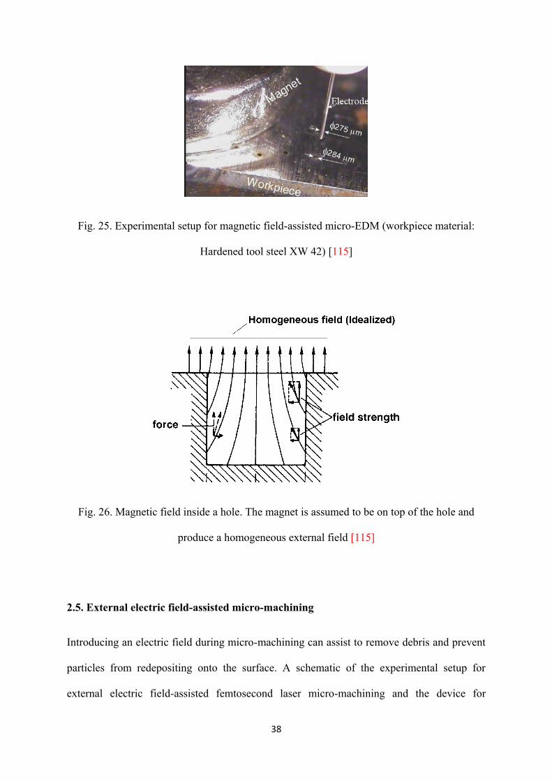
A permanent magnet can be employed to establish a magnetic field in the machining zone.
An experimental setup for magnetic field-assisted micro-EDM is shown in Fig. 25. By using
such configuration in micro-EDM process, higher hole depth can be achieved owing to
increase of the debris removal. The magnetic field inside the hole has vertical and horizontal
components. The schematic representation of the magnetic field acting on the debris particle
inside the hole being machined is given in Fig. 26, which indicates an increase in the vertical
component of the magnetic force will augment the transport of ferromagnetic debris out of
the hole. Conversely, the presence of the magnetic field causes some distortion in the tool
electrode and increase of the tool wear and surface roughness [115].
38
Fig. 25. Experimental setup for magnetic field-assisted micro-EDM (workpiece material:
Hardened tool steel XW 42) [115]
Fig. 26. Magnetic field inside a hole. The magnet is assumed to be on top of the hole and
produce a homogeneous external field [115]
2.5. External electric field-assisted micro-machining
Introducing an electric field during micro-machining can assist to remove debris and prevent
particles from redepositing onto the surface. A schematic of the experimental setup for
external electric field-assisted femtosecond laser micro-machining and the device for

39
providing an external electric field are presented in Fig. 27. Material removal with the
femtosecond laser is a complex process. At femtosecond time scale, free electrons absorb
laser energy and leave the sample surface in several picoseconds. The ultrashort laser pulses
with mJ- pulse energy produce sufficiently high peak power that leads to ionization of the
substrate material and therefore formation of the plasma. The presence of the plasma can lead
to a large number of micro/nano-sized particles being deposited on the substrate surface. By
introducing an electric field during the fs laser machining, redeposition of particles onto the
surface can be inhibited. For the charged particles to be removed by the electric force, the
particle weight needs to be smaller than the electric forces. Electric force is defined as
follows:
(2)
where F is the electric force experienced by the particle; q is the charge of an electron,
, V is the applied voltage between two plates and d is the distance between
the two plates. Particle weight is:
(3)
where rp is the radius of the particle; ra is the radius of the Si atom, 0.117 nm, ma is the mass
of the atom, and g is the gravity acceleration, 9.8 ms-2
.
When an external electric field is applied during the femtosecond laser micro-machining of
silicon, a significantly improved machined surface quality with much reduced amount of
surface contaminants is achieved, as depicted in Fig. 28 [116].

40
(a) (b)
Fig. 27. (a) Schematic of the experimental setup for external electric field-assisted laser
micro-machining (b) Device for providing an external electric field [116]
(a) (b)
Fig. 28. fs laser micro-machining of silicon a) without the external electric field. b) with the
external electric field [116]
2.6. Carbon nanofibre-assisted micro-machining
As schematically shown in Fig. 29, unlike the conventional EDM and powder assisted EDM,
carbon nanofibers can arrange themselves in the form of micro-chains by interlocking which
helps to form bridging networks between electrode and workpiece. Due to excellent electrical

41
conductivity of carbon nanofibre, it can be applied in micro-EDM dielectric fluid in order to
reduce the insulating strength of the dielectric fluid and increase the spark gap distance
between the electrode and workpiece. As a result, the frequency of electro discharge and the
material removal rate in the EDM of RB-SiC is improved. In addition, multiple fine
discharges are occurred under this situation, leading to a reduction in crater size on the
workpiece surface, and in turn, a better surface finish might be obtained. It has been found
that the addition of carbon nanofibre reduces the electrode wear and electrode tip concavity
[117].

42
Fig. 29. Schematic model for (a) conventional EDM and (b) carbon nanofiber-assisted micro-
EDM [117]
2.7. Vibration and magnetic field-assisted micro-machining
Simultaneous application of magnetic force and ultrasonic vibration in micro-machining
process can improve the efficiency, surface roughness and stability of the process. In
electrochemical micro-machining, it helps discharging dreg out of the electrode gap. Fig. 30
illustrates a schematic view of vibration and magnetic field-assisted electrochemical micro-
machining setup which is composed of a magnetic mechanism, DC (direct current) power
supply, pulse-generators, pump, flow meter, and filter [118].
Fig. 30. Schematic view of vibration and magnetic field-assisted electrochemical micro-
machining setup [118]
Polishing process can be improved by using a magnetostrictive vibrating polisher shown in
Fig. 31. The form accuracy of binderless tungsten carbide workpiece is enhanced to less than

43
100 nm P-V and the surface roughness is reduced to 3.3 nm Rz (0.4 nm Ra) by using this
polisher [119-121].
Fig. 31. 4-coil magnetostrictive vibrating polisher [120]
3. Combined hybrid micro-machining processes
In combined hybrid micro-machining, all the constituent micro-machining processes
simultaneously contribute to the material removal and affect the machining zone. Combined
hybrid micro-machining processes have giant potential to produce more complex parts with
enhanced material removal rate, surface integrity and dimensional accuracy in a relatively
short production time. Primary research in combined hybrid micro-machining field is on the
application of electrical and electrochemical phenomena. Although combined hybrid micro-
machining processes such as ECDM have been mostly used to fabricate 3D micro-shapes on
nonconductive materials like glass and quartz, there is still a lack of such processes for
manufacturing complicated 3D micro-structures. Table 4 summarizes the reported work in
the area of combined hybrid micro-machining.

44
Table 4. Combined hybrid micro-machining processes
Combined hybrid micro-
machining
Work material Primary characteristic
ECDM Glass [126-128, 131-132,137,
146-147, 150], Pyrex glass [130,
135, 139], Soda lime glass [133,
143, 152], Steel [142], Quartz
[140-141, 143], 100Cr6 steel
[149], Silicon nitride [129],
Borosilicate glass [148], Copper
[143], Tantalum [143], SS304
[151], Al2O3 [145], E-glass-fibre-
epoxy composite [134], Silica
glass [138]
Suitable for micro-machining of non-conductive
materials [126-141, 144-148, 150, 152]
Achieved surface roughness (Rq) for Pyrex glass is
nearly 0.08 µm [130]
ECDM milling Glass [136], Pyrex glass [134] Suitable for 3D micro-structuring of non-conductive
materials [134, 136]
Achieved surface roughness (Ra ) for Glass is 0.099 µm
[136]
Simultaneous ED-EC
milling
SUS304 [1, 153-156], T1 copper
[157], 1Cr18Ni9Ti stainless steel
[157]
Achieved surface roughness (Ra) for SS304 is 22 nm [1,
153-156]
ECM-Grinding SS321 [158] Achieved surface roughness (Ra) is 0.21 µm [158]
EDM- Electrorheological
fluid-assisted polishing
SUS304 [111],
Aluminium alloy [159]
Achieved surface roughness (Ra) for SUS304 is 0.06-
0.08 µm [111]
Laser drilling-Jet ECM 321 stainless [162] More than 90% reduction in recast [162]

45
3.1. Micro-electrochemical discharge machining
Micro-ECDM process involves a complex combination of the electrochemical (EC) reaction
and electrodischarge (ED) action. The electrochemical action helps the generation of the
positively charged ionic gas bubbles, e.g. hydrogen (H2). The electrical discharge action takes
place between the tool and the workpiece due to the breakdown of the insulating layer of the
gas bubbles as the DC power voltage is applied between the tool (or cathode) and the anode,
resulting in material removal due to melting, vaporisation of the workpiece material and
mechanical erosion. Gas bubble formation and sparking phenomena as in the ECDM process
are exhibited as shown in Fig. 32 [122].
Fig. 32. Material removal mechanism of ECDM operation [122]
The process involves a DC voltage being applied between the electrodes immersed in an
electrolytic solution as shown schematically in Fig. 33. The tool is generally used as a

46
cathode to avoid anodic dissolution. The anode has a large surface area as compared to the
tool and is kept at a distance from the cathode [123].
Fig. 33. Schematic of ECDM Process [124]
Several names had been used for this process such as electrochemical spark machining
(ECSM), electrochemical arc machining (ECAM), spark-assisted chemical engraving
(SACE) etc. [125].
A large number of studies have been reported on the investigation of different assets of
micro-ECDM [126-152], such as wettability of the tool electrode [126], gas film thickness
[127, 135, 139], different drilling regimes [128], characterization of various process
parameters and state variables [129, 131, 144, 147-148, 150], application of rectangular
voltage pulses in order to reduce HAZ [130], feasibility study of micro-machining of
different shapes and materials [132-134, 136, 142-143, 146, 151-152], material removal
mechanism [137], use of resistor-capacitor (RC) circuit [138], transition voltage [139],
material and shape of the tool electrode [140-141, 145] and simulation of the heat transfer

47
[149]. It is shown that applied voltage has more significant effects on MRR, radial overcut
(ROC), HAZ thickness than other machining parameters such as electrolyte concentration,
tool immersion depth and inter-electrode gap in micro-ECDM [129,150].
Fig. 34 depicts various 3D structures machined by using ECDM micro-milling process on
Pyrex glass [134]. It shows that the ECDM micro-milling process has great potential for the
3D micro-structuring of nonconductive and hard-brittle materials.
Fig. 34. Various examples of 3D micro-structures of Pyrex glass [134]
3.2. Simultaneous micro-ED/EC milling
In simultaneous micro-EDM and micro-ECM milling (SEDCM milling), material removal
phenomenon in low-resistivity deionized water is exploited in such a way that the
electrochemical reaction occurs concurrently with electrical discharge in a unique process.
Fig. 35 illustrates the fundamental mechanism of SEDCM milling. In this method, material is
removed layer-by-layer to maintain the original shape of electrode [1, 153-156].

48
Fig. 35. Principle of SEDCM milling [154]
SEDCM milling is capable of producing micro-shapes with enhanced surface integrity and
dimensional accuracy. Micro-shapes with 22 nm Ra can be obtained on SUS304. Fig. 36
shows two examples of three-dimensional micro-cavities with a central island machined by
micro-EDM milling and SEDCM milling, demonstrating the feasibility and capability of
SEDCM milling process [154]. However, this process causes excessive electrolytic-erosion
and workpiece surface damage as slight electrical conductivity always exists in deionized
water. It is recommended to apply nanosecond voltage pulse and epoxy resin side-insulated
tool electrode to suppress excessive electrolytic-erosion [157].

49
Fig. 36. 3D micro-cavities fabricated by different machining conditions: (a) micro- EDM
milling and (b) SEDCM milling (workpiece material: SUS304) [154]
3.3. Micro-ECM and micro-mechanical grinding
Hybrid process of electrochemical material removal and mechanical grinding for machining
of precision small holes was established in 2011. As demonstrated in Fig. 37, a spherical
metal rod with coated diamond abrasives as cathode tool rotates at high speed and removes
material electrochemically and mechanically for a pre-machined pilot hole. The pilot hole
with diameter of D0, which is smaller than the final hole diameter D1. It is essential that the
tool core is electrically conductive and the abrasive is electrically non-conductive. During the
machining process, the tool is charged negatively and the workpiece performs as the anode.
The abrasive particles (diamond particles) in the tool protrude beyond the conductive bond
surface (nickel layer). This establishes a small gap between the tool nickel layer and hole side
wall. In the proposed process, workpiece material removal occurs in two phases, as indicated
in Fig 37. Electrolytic action begins when the gap is filled with an electrolyte and the tool is
electrically charged. Phase 1 is entirely electrochemical action. In this phase, passivation film
occurs on the hole surface because passive electrolyte NaNO3 is used. Phase 2 is a
combination of electrochemical action and mechanical grinding. As the abrasive tool feeding
down, the gap decreases until the abrasives on the tool base comes into contact with the
workpiece. The abrasive grains act to remove the soft, non-reactive passivation layer, thus
exposing fresh metal for electrolytic reaction. Simultaneously, the electrolyte trapped
between the protruding abrasive grains and the workpiece forms tiny electrolytic cells, thus
electrochemical dissolution of workpiece materials occurs. So in phase 2 material is removed
from the workpiece surface by both electrochemical dissolution and mechanical abrasive

50
grinding. Phase 2 ends at the point where the maximum tool diameter is. For obtaining sharp
edges and high dimensional accuracy of hole, the tool should be insulated except the first half
of the sphere. So, there is no removal action taking place in phase 3. If the tool is not
insulated, the electrochemical dissolution will continue for the machined hole surface (phase
3) because of the electrical field between the machined hole surface and the tool, resulting in
a taper hole. The finest surface finish of 0.21 µm can be obtained in stainless steel 321 work
material [158].
Fig. 37. Schematic view of the proposed hybrid process of electrochemical removal and
grinding [158]
3.4. Micro-EDM and electrorheological fluid-assisted polishing (ERP)
Since there is very strong electric field between workpiece and electrode before discharge
occurrence in EDM, it is possible to induce the electric field to assist polishing in micro-
EDM. The principle of the combined machining process of EDM and ERP is schematically

51
shown in Fig. 38. The copper micro-tool electrode is positive pole, and workpiece of
conductive material is used as negative pole, which retains narrow gap between electrodes.
When the external electric field is applied, the material is melted and vaporized
instantaneously as result of intense heat generated in the gap. Meanwhile, the dispersed
particles aggregate into cluster and fibrous structure aligned in the electric line due to the
dielectrically polarized in ER fluid with fine abrasive particles, as shown in Fig 38. When the
chain of particles contacts with workpiece surface with the rotation of the micro-tool, the
abrasive particles indent into workpiece surface under normal pressure. In this technique,
alumina and SiC can be used as abrasives [111, 159].
Fig. 38. Schematic diagram of the proposed method using ER fluid and abrasive gifts [111]
3.5. Laser micro-drilling and jet ECM
Laser drilling assisted with jet electrochemical machining (JECM-LD) combines two
different sources of energy simultaneously: energy of photons (laser drilling) and energy of
ions (ECM). The electrolyte jet and the focused laser beam coaxially aligned with it creating
a contactless tool-electrode and strike against the same spot on the workpiece surface. During
JECM-LD, the workpiece material is removed with laser action in pulse width, and then

52
recast and spatter are reduced with electrochemical reaction in the inter-pulse of laser. Fig. 39
illustrates the principles of JECM-LD. It is found that the spatter is reduced more than 95%,
and recast is reduced more than 90% during the JECM-LD of 321 stainless steel compared
with laser drilling in ambient atmosphere conditions [160-162].
(a) In pulse width
(b) In the inter-pulse
Fig. 39. Principle scheme of JECM-LD [162]

53
4. Case studies on integration of hybrid micro-machining with other micro-machining
and assisted techniques
Hybrid micro-machining processes can be integrated with other micro-machining and
assisted methods so as to gain advantages of other techniques. The development and
application of these types of processes should be as such that they enhance the benefits and
minimize the potential drawbacks found in the individual hybrid techniques. This category of
processes gives new possibilities to machine materials or shapes with higher accuracy and
improved surface quality which could not be manufactured or achieved by single hybrid
micro-machining techniques. Despite its numerous advantages, a little work has been
performed in this field. Hence, development of this sort of micro-machining processes is a
promising area of research. The following paragraphs give details of the studies done on the
combination of hybrid micro-machining processes with other micro-machining and assisted
methods.
4.1. Combined and assisted hybrid processes
Vibration and magnetic field can be applied in combined hybrid processes to improve the
performance of these processes. An ultrasonic-vibrated electrolyte in micro-ECDM enhances
the machining depth by assuring an adequate flow of electrolyte for spark generation and chip
removal in the gap between the tool and the workpiece [163]. Moreover, it is shown that the
magneto-hydrodynamic convection induced by the magnetic field can effectively enhance
electrolyte circulation, which contributes to higher machining performance. The
improvement in the geometry accuracy achieved in magnetic field-assisted micro-ECDM of

54
glass is 23.8% while that in machining time reaches 57.4%. A schematic diagram of the
magnetic field-assisted ECDM apparatus is shown in Fig. 40 [164]. In vibration-assisted
micro-ECDM drilling of borosilicate glass, the machining depth increases from 320 μm to
550 μm compared to conventional micro-ECDM drilling results [163].
Fig. 40. Schematic diagram of the magnetic field-assisted ECDM apparatus [164]
4.2. Combined and sequential hybrid processes
In this method, micro-structures are machined by ECDM milling and then ground by PCD
tools to improve the surface quality. The concept of this hybrid process is shown in Fig. 41.

55
Fig. 41. Concept of the hybrid machining process [165]
A surface roughness, Ra, of 0.05 μm, sharp rims and edges can be achieved in glass
workpiece by using this process. Fig. 42 shows a micro-groove and column in a soda lime
glass workpiece machined by ECDM and after the postmachining step [165].
Fig. 42. Micro-structures machined by (a,c) ECDM and (b,d) then ground by a PCD tool
[165]
56
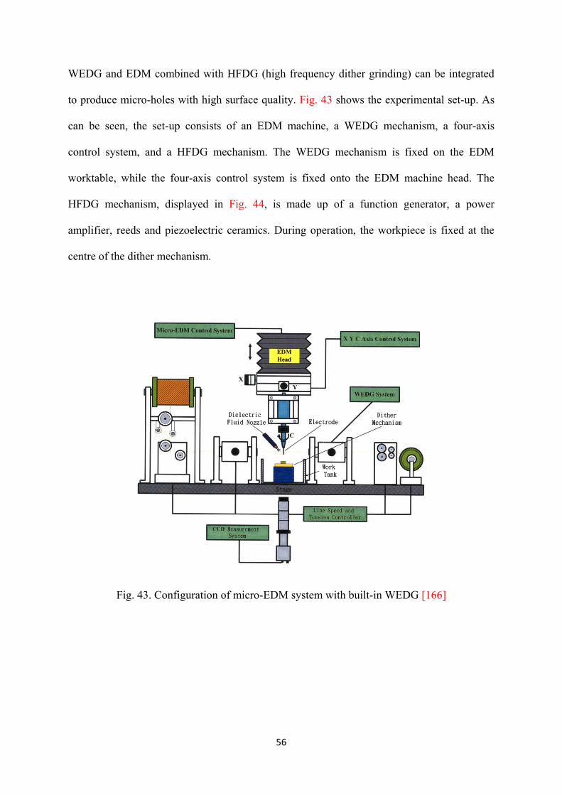
WEDG and EDM combined with HFDG (high frequency dither grinding) can be integrated
to produce micro-holes with high surface quality. Fig. 43 shows the experimental set-up. As
can be seen, the set-up consists of an EDM machine, a WEDG mechanism, a four-axis
control system, and a HFDG mechanism. The WEDG mechanism is fixed on the EDM
worktable, while the four-axis control system is fixed onto the EDM machine head. The
HFDG mechanism, displayed in Fig. 44, is made up of a function generator, a power
amplifier, reeds and piezoelectric ceramics. During operation, the workpiece is fixed at the
centre of the dither mechanism.
Fig. 43. Configuration of micro-EDM system with built-in WEDG [166]

57
Fig. 44. Schematic of HFDG mechanism [166]
First, a circular rod of tungsten carbide is machined using WEDG. The machined rod is then
used to drill micro-holes on the workpiece. Alumina (Al2O3) particles are added to the slurry
in the tank. The EDM machine is coupled with the HFDG mechanism to polish the micro-
holes by upward and downward machining. The entire operation does not involve any
dismounting of the machining electrode or tool, thus avoiding the eccentric problem of the
rotating tool. HFDG method can reduce machined surface roughness (Rmax) on Hymu 80
workpiece from 2.12 µm to 0.85 µm with micro-cracks eliminated [166].
4.3. Sequential and assisted hybrid processes
Production of cooling holes less than 1mm diameter in electrically non-conductive ceramic
coated nickel alloy presents a number of problems as the preferred ceramic material is
alumina. This is effectively an electrical insulator with a specific electrical resistance ≥100
Ωcm and therefore EDM is not viable. One solution is the use of USM to penetrate the
ceramic coating followed by tool vibration-assisted micro-EDM drilling. Fig. 45 shows

58
general views of the experimental set-up for this process. The use of appropriate tool material
is critical in this hybrid process in order to obtain effective USM/EDM operation. Preferred
USM tool materials are not ideal for EDM and vice versa. Mild steel is proved reasonably
effective; however, tool wear is significant [167].
Fig. 45. Views of the experimental set-up [167]
5. Future research opportunities

59
The review of present literature gives chances for novel commercial, technological and
scientific advancements in the field of hybrid micro-machining processes, some of which are
explained in the following.
5.1 Study on mechanisms involved in processes
Within hybrid micro-machining processes different forms of energy or forms of energy
caused in different ways are used at the same time at the same zone of impact. Hence, further
research is required in order to fully understand the mechanics and mechanisms involved in
hybrid micro-machining processes which is primarily influenced by simultaneous
combination of processes and or energy sources, and requires extensive research in chip
removal process.
5.2 Research on modelling techniques
More research on numerical and multiscale modelling approaches is required in order to
simulate the hybrid micro-machining processes. Finite element analysis, multiphysics
modelling, molecular dynamic simulation and etc. can be combined in order to simulate
hybrid micro-machining processes. Development of such modelling methods will aid in
gaining better understanding and optimizing these processes.
5.3 Development of specific multi-axis ultraprecision machine tools
Since hybrid micro-machining processes are based on the simultaneous and controlled
interaction of process mechanisms and/or energy sources/tools, specific multi-axis

60
ultraprecision machine tools are required to be developed considering tough requirements
such as high thermal stability, high static and dynamic stiffness, feed drives and control
systems with high accuracy and short response time associated with large bandwidth and low
following error for multi-axes interpolation, low deformation and vibration, precise spindle
bearings and linear guides and high resolution of linear and rotary motions, minimization
and/or compensation of thermal effects and minimization and compensation of static and
dynamic positioning errors. Multi-axis ultraprecision machine tools are also needed to be
developed for hybrid micro-machining processes in order to perform various tasks in diverse
directions and angles. Furthermore, an enhanced numerical control is necessary to achieve
smooth tool movements without changes in the feed rate, responsible for high accuracies of
micro-structures.
5.4 Opportunities for improving process monitoring techniques
Process monitoring systems are needed to characterize, control, and improve hybrid micro-
machining processes. Monitoring may be applied to parameters or variables such as
temperature, cutting force, chatter, vibration, etc. Process monitoring through acoustic
emission, force and vibration signals draw a great deal of attention. However, it is desirable
to use multiple sensors to realize the smart and intelligent machine tool [6].
5.5 Development of on-machine tool fabrication and metrology techniques
The motivation of on-machine tool making is to avoid realignment and clamping errors.
Thus, on-machine tool fabrication methods can be developed and integrated with hybrid
micro-machining processes. Another crucial facet needs to be considered is uncertainty of the

61
achievable accuracy in hybrid micro-machining processes. A non-contact, on-machine
metrology system is indispensable to achieve and maintain high quality of the machined
micro-parts and avoid error introduced by the re-fixture after the offline measurement.
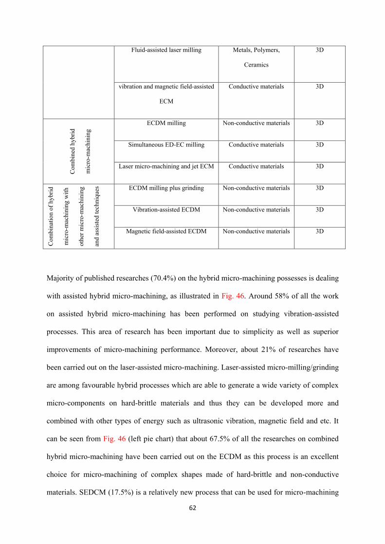
5.6 Establishment of novel processes
Necessities for the fabrication of miniature/micro-products with complex shapes have made
new challenges for designing new hybrid micro-machining processes. A few numbers of
hybrid micro-machining processes have been developed for manufacturing 3D complex
micro-components. Table 5 lists the major hybrid and combination of hybrid micro-
machining with other micro-machining and assisted techniques that can be regarded as
effective and successful processes for manufacturing 3D micro-structures.
Table 5. Successful hybrid and combination of hybrid micro-machining with other micro-
machining and assisted techniques
Hybrid process Successful sub-process Feasible material Geometric
complexity
Ass
iste
d h
yb
rid m
icro
-mac
hin
ing m
achin
ing
Vibration-assisted milling/grinding Conductive, Non-
conductive materials,
Polymers
3D
Vibration-assisted EDM milling Conductive materials 3D
Laser-assisted milling/grinding Conductive, Non-
conductive materials,
Hard-brittle materials
3D
62
Fluid-assisted laser milling Metals, Polymers,
Ceramics
3D
vibration and magnetic field-assisted
ECM
Conductive materials 3D
Co
mb
ined
hy
bri
d
mic
ro-m
ach
inin
g
ECDM milling Non-conductive materials 3D
Simultaneous ED-EC milling Conductive materials 3D
Laser micro-machining and jet ECM Conductive materials 3D
Co
mb
inat
ion
of
hy
bri
d
mic
ro-m
ach
inin
g w
ith
oth
er m
icro
-mac
hin
ing
and
ass
iste
d t
ech
niq
ues
ECDM milling plus grinding Non-conductive materials 3D
Vibration-assisted ECDM Non-conductive materials 3D
Magnetic field-assisted ECDM Non-conductive materials 3D
Majority of published researches (70.4%) on the hybrid micro-machining possesses is dealing
with assisted hybrid micro-machining, as illustrated in Fig. 46. Around 58% of all the work
on assisted hybrid micro-machining has been performed on studying vibration-assisted
processes. This area of research has been important due to simplicity as well as superior
improvements of micro-machining performance. Moreover, about 21% of researches have
been carried out on the laser-assisted micro-machining. Laser-assisted micro-milling/grinding
are among favourable hybrid processes which are able to generate a wide variety of complex
micro-components on hard-brittle materials and thus they can be developed more and
combined with other types of energy such as ultrasonic vibration, magnetic field and etc. It
can be seen from Fig. 46 (left pie chart) that about 67.5% of all the researches on combined
hybrid micro-machining have been carried out on the ECDM as this process is an excellent
choice for micro-machining of complex shapes made of hard-brittle and non-conductive
materials. SEDCM (17.5%) is a relatively new process that can be used for micro-machining
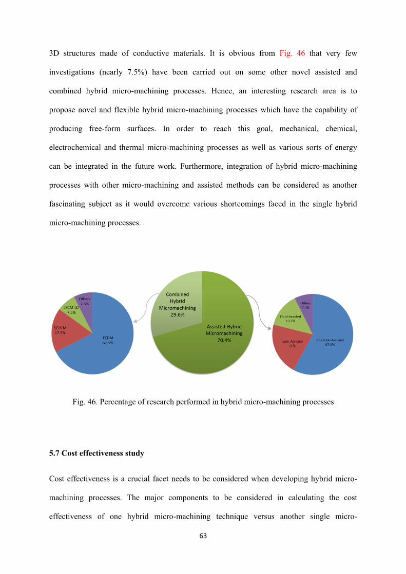
63
3D structures made of conductive materials. It is obvious from Fig. 46 that very few
investigations (nearly 7.5%) have been carried out on some other novel assisted and
combined hybrid micro-machining processes. Hence, an interesting research area is to
propose novel and flexible hybrid micro-machining processes which have the capability of
producing free-form surfaces. In order to reach this goal, mechanical, chemical,
electrochemical and thermal micro-machining processes as well as various sorts of energy
can be integrated in the future work. Furthermore, integration of hybrid micro-machining
processes with other micro-machining and assisted methods can be considered as another
fascinating subject as it would overcome various shortcomings faced in the single hybrid
micro-machining processes.
Fig. 46. Percentage of research performed in hybrid micro-machining processes
5.7 Cost effectiveness study
Cost effectiveness is a crucial facet needs to be considered when developing hybrid micro-
machining processes. The major components to be considered in calculating the cost
effectiveness of one hybrid micro-machining technique versus another single micro-

64
machining process can be the initial capital investment, total micro-machining time, micro-
machining cost per minute, labour cost per minute, flexibility and product quality.
5.8 Industrial implementation
Majority of hybrid micro-machining processes are still at the research stage, and only a few
of them have so far found their way into industrial applications. Technology transfer is
known to be a difficult process. A typical technology takes up several years to move from the
research laboratory to become a general practice in industry. Industry uses several
investigative methods before adopting a new technology. As discussed earlier, cost
effectiveness is a momentous aspect which is considered by industry. More research on
industrial implementation of hybrid micro-machining processes is required to be performed.
6. Conclusion
Hybrid micro-machining processes enable us to improve process capabilities in terms of the
surface roughness, material removal rate, tool life and geometrical accuracy. To fabricate
complex micro-parts on hard-to-machine and multi-materials, a hybrid micro-machining
process can be extremely beneficial so as to obtain higher machining efficiency. However,
relying on a proper comprehension of the process-material interaction, process parameters
should be opted in an appropriate approach. Otherwise, undesirable consequences such as
deteriorated surface finish, micro-cracks, etc. can be obtained.
From the literature review presented in this paper, it is evident that a few attempts have been
made to develop novel combined hybrid micro-machining processes. The authors believe that
combined hybrid micro-machining processes have great potential for fabricating 3D complex
65
micro-components with high accuracy and surface quality. Among them, ECDM milling is a
promising process for micro-machining complex shapes made of hard-brittle and non-
conductive materials. Moreover, laser-assisted micro-milling has the capability to produce
free-form surfaces on hard-brittle and non-conductive materials. These processes can be
integrated with other assisted and sequential processes so as to improve surface integrity,
machining rate and geometrical accuracy of the machined micro-parts.
Hybrid micro-machining processes are just starting to be developed in many features, leaving
ample opportunity for future investigation. The process mechanisms, simulation methods,
ultraprecision machine tools for hybrid micro-machining, process monitoring and metrology
techniques, novel hybrid micro-machining techniques, cost effectiveness and industrial
implementation are among those scopes need to be explored.
Acknowledgment
The authors would like to thank EPSRC (EP/K018345/1) to provide financial support to this research.
References
[1] M.D. Nguyen, Simultaneous micro-EDM and micro-ECM in low-resistivity deionized
water, PhD thesis, National University of Singapore, 2013
[2] W. Chang, Development of Hybrid Micro Machining Approaches and Test-bed, PhD
thesis, Heriot-Watt University, 2012
[3] P. Rai-Choudhury, Handbook of lithography, micromachining and microfabrication, SPIE
Press. (1997)
66
[4] M. J. Madou, Fundamentals of microfabrication and nanotechnology. 3rd edition, CRC
Press (2009)
[5] P. Cardoso, J. P. Davim, A brief review on micro-machining of materials. Rev. Adv.
Mater. Sci. 30 (2012) 98-102
[6] P. Piljek, Z. Keran, M. Math, Micro-machining-review of literature from 1980 to 2010.
Interdisciplinary Description of Complex Systems 12 (1) (2014) 1-27
[7] MEMS/NEMS Handbook Techniques and Applications Volume 3, Edited by Cornelius T.
Leondes, (2006) Springer publications
[8] X. Luo, K. Cheng, D. Web, F. Wardle, Design of ultraprecision machine tools with
applications to manufacture of miniature and micro components, Journal of Materials
Processing Technology. 167 (2005) 515-528.
[9] H. El-Hofy, Advanced machining processes, McGraw-Hill, 2005
[10] Z. Zhu , V.G. Dhokia, A. Nassehi, S.T. Newman, A review of hybrid manufacturing
processes-state of the art and future perspectives, International Journal of Computer
Integrated Manufacturing. 26:7 (2013) 596-615
[11] K.P. Rajurkara, D. Zhua, J.A. McGeoughb, J. Kozakc, A. De Silva, New developments
in electrochemical machining. CIRP Annals: Manufacturing Technology. 48 (2) (1999) 567-
579.
[12] J. Kozak, K.P. Rajurkar, Hybrid machining process evaluation and development,
Proceedings of 2nd International conference on machining and measurements of sculptured
surfaces, Keynote Paper, 20–22 September, Krakow, Poland. Krakow: The Institute of Metal
Cutting (IOS), (2000) 501–536.
67
[13] D.K. Aspinwall, R.C. Dewes, J.M. Burrows, M.A. Paul, Hybrid high speed machining
(HSM): system design and experimental results for grinding/HSM and EDM/HSM, CIRP
Annals-Manufacturing Technology, 50 (1) (2001) 145–148.
[14] D.T. Curtis, S.L. Soo, D.K. Aspinwall, C. Sage, Electrochemical superabrasive
machining of a nickel-based aeroengine alloy using mounted grinding points, CIRP Annals-
Manufacturing Technology. 58 (1) (2009) 173-176.
[15] B. Lauwersa, Surface Integrity in Hybrid Machining Processes, Procedia Engineering 19
(2011) 241-251.
[16] C.H. She, C.W. Hung, Development of multi-axis numerical control program for mill-
turn machine, Proceedings of the Institution of Mechanical Engineers Part B-Journal of
Engineering Manufacture. 222 (6) (2008) 741-745.
[17] B. Lauwers, F. Klocke, A. Klink, A. Erman Tekkaya, R. Neugebauer, D. Mcintosh,
Hybrid processes in manufacturing. CIRP Annals - Manufacturing Technology 63 (2014)
561-583
[18] U. Heisel, R. Eisseler, R. Eber, J. Wallaschek, J. Twiefel, M. Huang, Ultrasonic-assisted
machining of stone, Prod. Eng. Res. Devel. (2011) 5:587-594
[19] D.E. Brehl, T.A. Dow, Review of vibration-assisted machining, Precision Engineering.
32 (2008) 153-172.
[20] T. Tawakoli, B. Azarhoushang, M. Rabiey, Ultrasonic assisted dry grinding of
42CrMo4, Int J Adv Manuf Technol. (2009) 42:883-891.
[21] B. Azarhoushang, J. Akbari, Ultrasonic-assisted drilling of Inconel 738-LC,
International Journal of Machine Tools & Manufacture. 47 (2007) 1027-1033.
68
[22] K.M. Li, S. L. Wang, Effect of tool wear in ultrasonic vibration-assisted micro-milling,
Proc IMechE Part B: J Engineering Manufacture, 228(6) (2014) 847-855 .
[23] H. Onikura, R. Inoue, K. Okuno, O. Ohnishi, Fabrication of Electroplated Micro
Grinding Wheels and Manufacturing of Micro-structures with Ultrasonic Vibration, Key
Engineering Materials. 238-239 (2003) 9-14.
[24] H. Onikura, O. Ohnishi, Y. Take, Fabrication of Micro Carbide Tools by Ultrasonic
Vibration Grinding, CIRP Annals - Manufacturing Technology, 49(1) (2000) 257-260
[25] J. S. Lee, D. W. Lee, Y. H. Jung, W. S. Chung, A study on micro-grooving
characteristics of planar lightwave circuit and glass using ultrasonic vibration cutting, Journal
of Materials Processing Technology. 130-131 (2002) 396-400
[26] A. H. Ammouri, R. F. Hamade, BUEVA: a bi-directional ultrasonic elliptical vibration
actuator for micro-machining, Int J Adv Manuf Technol. 58 (2012) 991-1001
[27] G. D. Kim, B. G. Loh, Direct Machining of Micro Patterns on Nickel Alloy and Mold
Steel by Vibration Assisted Cutting, International journal of precision engineering and
manufacturing 12(4) (2011) 583-588.
[28] G. D. Kim, B. G. Loh, Cutting Force Variation with Respect to Tilt Angle of Trajectory
in Elliptical Vibration V-grooving, International journal of precision engineering and
manufacturing. 14(10) (2013)1861-1864.
[29] B. Brocato, Micro-machining Using EVAM (Elliptical Vibration Assisted Machining),
Master's Thesis, North Carolina State University, 2005.
69
[30] D. E. Brehl, T.A. Dow, 3-D micro-structure creation using elliptical vibration assisted
machining, ASPE Proceedings, Vibration Assisted Machining Technology, April 16-17,
(2007), The Carolina Inn, Chapel Hill, NC.
[31] C. Huawei,C. Minglong, L. Youjie,Z. Deyuan, Development of Integrated Precision
Vibration-Assisted Micro-Engraving System, Trans. Tianjin Univ. 17 (2011) 242-247.
[32] S. Koshimizu, S. Aoki, Micro-Grooving of Glass Using Small-Diameter Diamond
Grindstone with Ultrasonic Vibration, Advanced Materials Research. 797 (2013) 368-373.
[33] Z. Z. Wang, Y. B. Guo, Y. B. Wu, Development of a Two-dimensional Ultrasonic
Vibration Assisted Machining Technology with Tool Vibration, Key Engineering Materials.
487 (2011) 419-422.
[34] C. Zhang, E. Brinksmeier, R. Rentsch, Micro-USAL technique for the manufacture of
high quality micro-structures in brittle materials, Precision Engineering 30 (2006) 362-372.
[35] C. Zhang, R. Rentsch, E. Brinksmeier, Advances in micro ultrasonic assisted lapping of
micro-structures in hard–brittle materials: a brief review and outlook, International Journal of
Machine Tools & Manufacture. 45 (2005) 881-890
[36] H. Suzuki, T. Moriwaki, T. Okino, Y. Ando, Development of Ultrasonic Vibration
Assisted Polishing Machine for Micro Aspheric Die and Mold, CIRP Annals - Manufacturing
Technology. 55 (1) (2006) 385-388.
[37] H. Suzuki, S. Hamada, T. Okino, M. Kondo, Y. Yamagata, T. Higuchi, Ultraprecision
finishing of micro-aspheric surface by ultrasonic two-axis vibration assisted polishing, CIRP
Annals - Manufacturing Technology. 59 (2010) 347-350.
70
[38] S. K. Chee, H. Suzuki, M. Okada, T. Yano, T. Higuchi, W. Lin, Precision Polishing of
Micro Mold by Using Piezoelectric Actuator Incorporated with Mechanical Amplitude
Magnified Mechanism, Advanced Materials Research. 325 (2011) 470-475.
[39] T. Endo, T. Tsujimoto, K. Mitsui, Study of vibration-assisted micro-EDM-The effect of
vibration on machining time and stability of discharge, Precision Engineering. 32 (2008) 269-
277.
[40] M. Mahardika, G. S. Prihandana, T. Endo, T. Tsujimoto, N. Matsumoto, B. Arifvianto,
K. Mitsui, The parameters evaluation and optimization of polycrystalline diamond micro-
electrodischarge machining assisted by electrode tool vibration, Int J Adv Manuf Technol. 60
(2012) 985-993.
[41] H. Huang, H. Zhang, L. Zhou, H. Y. Zheng, Ultrasonic vibration assisted
electrodischarge machining of microholes in Nitinol, J. Micromech. Microeng. 13 (2003)
693-700.
[42] D. Ghiculescu, N. I. Marinescu, S. Nanu, D. Ghiculescu, G. Kakarelidis, FEM study of
synchronization between pulses and tool oscillations at ultrasonic aided
microelectrodischarge machining, Nonconventional Technologies Review. 3 (2010)19-25.
[43] A. W. J. Hsue, J.J. Wang, C. H. Chang, Milling Tool of Micro-EDM by Ultrasonic
Assisted Multi-axial Wire Electrical Discharge Grinding Processes, Proceedings of the
ASME 2012 International Manufacturing Science and Engineering Conference MSEC2012
June 4-8, (2012) Notre Dame, Indiana, USA.
[44] S. Mastud, M. Garg, R. Singh, J. Samuel, S. Joshi, Experimental characterization of
vibration-assisted reverse micro electrical discharge machining (EDM) for surface texturing,

71
Proceedings of the ASME 2012 International Manufacturing Science and Engineering
Conference MSEC2012,June 4-8, (2012) Notre Dame, Indiana, USA.
[45] A. Ruszaj, M. Zybura, R. Zurek, G. Skrabalak, Some aspects of the electrochemical
machining process supported by electrode ultrasonic vibrations optimization, Proceedings of
the Institution of Mechanical Engineers, Part B: Journal of Engineering Manufacture. 217
(2003) 1365-1371.
[46] B. Bhattacharyya, M. Malapati, J. Munda, A. Sarkar, Influence of tool vibration on
machining performance in electrochemical micro-machining of copper, International Journal
of Machine Tools & Manufacture. 47 (2007) 335-342.
[47] B. Ghoshal, B. Bhattacharyya, Influence of vibration on micro-tool fabrication by
electrochemical machining, International Journal of Machine Tools & Manufacture. 64
(2013) 49-59.
[48] B. Ghoshal, B. Bhattacharyya, Shape control in micro borehole generation by EMM
with theassistance of vibration of tool, Precision Engineering. 38 (2014) 127-137.
[49] G. L. Chern, Y. C. Chang, Using two-dimensional vibration cutting for micro-milling,
International Journal of Machine Tools & Manufacture. 46 (2006) 659-666.
[50] G. L. Chern, H. J. Lee, Using workpiece vibration cutting for micro-drilling, Int J Adv
Manuf Technol. 27 (2006) 688-692.
[51] H. Lian, Z. Guo, Z. Huang, Y. Tang, J. Song, Experimental research of Al6061 on
ultrasonic vibration assisted micro-milling, Procedia CIRP 6 ( 2013 ) 561-564.

72
[52] J. H. Ko, K. C. Shaw, H. K. Chua, R. M. Lin, Cusp Error Reduction under High Speed
Micro/Meso-Scale Milling with Ultrasonic Vibration Assistance, International journal of
precision engineering and manufacturing. 12(1) (2011) 15-20.
[53] K. Egashira, K. Mizutani,T. Nagao, Ultrasonic Vibration Drilling of Microholes in
Glass, CIRP Annals - Manufacturing Technology. 51(1) (2002) 339-342.
[54] M. Aziz, O. Ohnishi, H. Onikura, Novel micro deep drilling using micro long flat drill
with ultrasonic vibration, Precision Engineering. 36 (2012) 168-174.
[55] A. C. Wang, B. H. Yan, X. T. Li, F. Y. Huang, Use of micro ultrasonic vibration lapping
to enhance the precision of microholes drilled by micro electrodischarge machining,
International Journal of Machine Tools & Manufacture. 42 (2002) 915-923.
[56] C. Gao, Z. Liu, A study of ultrasonically aided micro-electrical-discharge machining by
the application of workpiece vibration, Journal of Materials Processing Technology. 139
(2003) 226-228.
[57] M. P. Jahan, T. Saleh, M. Rahman, Y. S. Wong, Development, Modeling, and
Experimental Investigation of Low Frequency Workpiece Vibration-Assisted Micro-EDM of
Tungsten Carbide, J. Manuf. Sci. Eng. 132(5) (2010) 054503.
[58] M.P. Jahan, T. Saleh, M. Rahman, Y.S. Wong, Study of Micro-EDM of Tungsten
Carbide with Workpiece Vibration, Advanced Materials Research, , 264-265 (2011) 1056-
1061.
[59] M. P. Jahan, M. Rahman, Y. S. Wong, L. Fuhua, On-machine fabrication of high-aspect-
ratio micro-electrodes and application in vibration-assisted micro-electrodischarge drilling of
tungsten carbide, Proceedings of the Institution of Mechanical Engineers, Part B: Journal of
Engineering Manufacture. 224 (2010) 795-814.

73
[60] M.P. Jahan, Y.S. Wong, M. Rahman, Evaluation of the effectiveness of low frequency
workpiece vibration in deep-hole micro-EDM drilling of tungsten carbide, Journal of
Manufacturing Processes 14 (2012) 343-359.
[61] J. C. Hung, J. K. Lin, B. H. Yan, H. S. Liu, P. H. Ho, Using a helical micro-tool in
micro-EDM combined with ultrasonic vibration for micro-hole machining, J. Micromech.
Microeng. 16 (2006) 2705-2713.
[62] H. Tong, Y. Li, Y. Wang, Experimental research on vibration assisted EDM of micro-
structures with non-circular cross-section, Journal of materials processing technology. 208
(2008) 289-298.
[63] R. Garna, A. Schubert, H. Zeidler, Analysis of the effect of vibrations on the micro-
EDM process at the workpiece surface, Precision Engineering. 35 (2011) 364-368.
[64] Z.Y. Yu, Y. Zhang, J. Li, J. Luan, F. Zhao, D. Guo, High aspect ratio micro-hole drilling
aided with ultrasonic vibration and planetary movement of electrode by micro-EDM, CIRP
Annals - Manufacturing Technology. 58 (2009) 213-216.
[65] M. M. Sundaram, G. B. Pavalarajan, K. P. Rajurkar, A Study on Process Parameters of
Ultrasonic Assisted Micro EDM Based on Taguchi Method, Journal of Materials Engineering
and Performance. 17 (2008) 210-215.
[66] H. Tong, Y. Li, Y. Wang, Vibration-assisted servo scanning 3D micro EDM, J.
Micromech. Microeng. 18 (2008) 025011.
[67] K.T. Hoang, S.H. Yang, A study on the effect of different vibration-assisted methods in
micro-WEDM, Journal of Materials Processing Technology. 213 (2013) 1616-1622.
74
[68] Z. Liu, H. Zhang, H. Chen, Y. Zeng, Investigation of material removal rate in micro
electrochemical machining with lower frequency vibration on workpiece, Int. J. Machining
and Machinability of Materials. 14(1) (2013) 91-104.
[69] B. Kang, G. W. Kim, M. Yang, S. H. Cho, J. K. Park, A study on the effect of ultrasonic
vibration in nanosecond laser machining, Optics and Lasers in Engineering. 50 (2012) 1817-
1822.
[70] H. Y. Zheng, H. Huang, Ultrasonic vibration-assisted femtosecond laser machining of
microholes, J. Micromech. Microeng. 17 (2007) N58-N61.
[71] S. U. Je, D. W. Kim, H. S. Lee, C. N. Chu, Micro EDM with Ultrasonic Work Fluid
Vibration for Deep Hole Machining, Journal of the Korean Society of Precision Engineering.
22 (7) (2005) 47-53.
[72] D. J. Kim, S. M. Yi, Y. S. Lee, Ch. N. Chu, Straight hole micro EDM with a cylindrical
tool using a variable capacitance method accompanied by ultrasonic vibration, J. Micromech.
Microeng. 16 (2006) 1092-1097.
[73] T. Ichikawa, W. Natsu, Study on Machining Characteristics of Ultrasonic Vibration
Assisted Micro-EDM, Applied Mechanics and Materials. 217-219 (2012) 2163-2166.
[74] T. Ichikawa, W. Natsu, Realization of micro-EDM under ultra-small discharge energy
by applying ultrasonic vibration to machining fluid, Procedia CIRP. 6 (2013) 326-331.
[75] J. K. Park, J. W. Yoon, M. C. Kang, S. H. Cho, Surface effects of hybrid vibration-
assisted femtosecond laser system for micro-hole drilling of copper substrate, Trans.
Nonferrous Met. Soc. China. 22 (2012) 801-807.

75
[76] J. K. Park, J. W. Yoon, S. H. Cho, Vibration assisted femtosecond laser machining on
metal, Optics and Lasers in Engineering. 50 (2012) 833-837.
[77] W-S Chu, C-S Kim, H-T Lee, J-O Choi, J-I Park, J-H Song, K-H Jang, S-H Ahn, Hybrid
Manufacturing in Micro/Nano Scale: A Review. International journal of precision
engineering and manufacturing-green technology 1(1) (2014) 75-92.
[78] S. Sun, M. Brandt, M. S. Dargusch, Thermally enhanced machining of hard-to-machine
materials-A review, International Journal of Machine Tools & Manufacture. 50 (2010) 663-
680.
[79] R. K. Singh, Laser Assisted Mechanical Micro-machining of Hard-to-Machine
Materials, PhD thesis, Georgia Institute of Technology December 2007.
[80] R. Singh, S. N. Melkote, Characterization of a hybrid laser-assisted mechanical micro-
machining (LAMM) process for a difficult-to-machine material, International Journal of
Machine Tools & Manufacture. 47 (2007) 1139-1150.
[81] R. Singh, M. J. Alberts, S. N. Melkote, Characterization and prediction of the heat-
affected zone in a laser-assisted mechanical micro-machining process, International Journal
of Machine Tools & Manufacture. 48 (2008) 994-1004.
[82] A. R. Shayan, H. B. Poyraz, D. Ravindra, M. Ghantasala, J. A. Patten, Force analysis,
mechanical energy and laser heating evaluation of scratch tests on silicon carbide (4H-SiC) in
micro-laser assisted machining (μ-lam) process, Proceedings of the ASME 2009 International
Manufacturing Science and Engineering Conference, MSEC2009 , October 4-7, (2009), West
Lafayette, Indiana, USA.
[83] M. Kumar, Laser assisted micro milling of hard materials, PhD thesis, Georgia Institute
of Technology, 2011.
76
[84] S. Melkote, M. Kumar, F. Hashimoto, G. Lahoti, Laser assisted micro-milling of hard-
to-machine materials, CIRP Annals - Manufacturing Technology. 58 (2009) 45-48.
[85] M. Kumar, S. N. Melkote, Process capability study of laser assisted micro milling of a
hard-to-machine material, Journal of Manufacturing Processes. 14 (2012) 41-51.
[86] M. Kumar, S. N. Melkote, R. M’Saoubi, Wear behavior of coated tools in laser assisted
micro-milling of hardened steel, Wear. 296 (2012) 510-518.
[87] N. Shen, H. Ding, Thermo-mechanical Coupled Analysis of Laser-assisted Mechanical
Micromilling of Difficult-to-machine Metal Alloys Used for Bio-implant, International
journal of precision engineering and manufacturing. 14(10) (2013)1677-1685.
[88] H. Ding, N. Shen, Y. C. Shin, Thermal and mechanical modeling analysis of laser-
assisted micro-milling of difficult-to-machine alloys, Journal of Materials Processing
Technology. 212 (2012) 601- 613.
[89] Z. Mohid, N. M.Warap, E. A. Rahim, M. R. Ibrahim, M.I.S Ismail, Study on Laser
Assisted Micro Milling (LAMM) Processing Characteristic Titanium Alloy (Ti6Al4V) using
TiAlN coated carbide micro ball mill, International conference on micromanufacturing
(ICOMM) (2014), No. 31.
[90] Z. Mohid, N. M. Warap, S. Hassan, M.I.S. Ismail, R. Ibrahim, E. A. Rahim, Numerical
Analysis of Laser Heating for Laser Assisted Micro Milling Application, Applied Mechanics
and Materials. 465-466 (2014) 720-724.
[91] E. A. Rahim, Z. Mohid, N. M. Warap, M. R. Ibrahim, M.I.S Ismail, A Prediction of
Laser Spot-to-Cutting Tool Distance in Laser Assisted Micro Milling, International
conference on micromanufacturing (ICOMM) (2014) No. 32.

77
[92] W. Chang, X. Luo, Q. Zhao, J. Sun, Y. Zhao, Laser assisted micro grinding of high
strength materials, Key Engineering Materials. 496 (2012) 44-49.
[93] A. K. M. De Silva, P. T. Pajak, D. K. Harrison, J. A. McGeough, Modelling and
Experimental Investigation of Laser Assisted Jet Electrochemical Machining. CIRP Annals -
Manufacturing Technology, 53 (1) (2004) 179-182
[94] P. T. Pajak, A. K. M. De Silva, D. K. Harrison, J. A. McGeough, Precision and
Efficiency of Laser Assisted Jet Electrochemical Machining. Precision Engineering, 30 (3)
(2006) 288-298
[95] A. K. M. De Silva, P. T. Pajak, J. A. McGeough, D. K. Harrison, Thermal Effects in
Laser Assisted Jet Electrochemical Machining. CIRP Annals - Manufacturing Technology,
60 (1) (2011) 243-246
[96] P. T. Pajak, A. K. M. De Silva, J. A. McGeough, D. K. Harrison., Modelling the Aspects
of Precision and Efficiency in Laser-Assisted Jet Electrochemical Machining (LAJECM).
Journal of Materials Processing Technology, 149 (1-3) (2004) 512-518
[97] V. Tangwarodomnukun, Towards damage-free micro-fabrication of silicon substrates
using a hybrid laser-waterjet technology, PhD Thesis, The University of New South Wales,
2012.
[98] V. Tangwarodomnukun, J. Wanga, C.Z. Huang, H.T. Zhu, An investigation of hybrid
laser-waterjet ablation of silicon substrates, International Journal of Machine Tools &
Manufacture. 56 (2012) 39-49.
[99] J. J. J. Kaakkunen, M. Silvennoinen, K. Paivasaari, P. Vahimaa, Water-Assisted
Femtosecond Laser Pulse Ablation of High Aspect Ratio Holes, Physics Procedia. 12 (2011)
89-93.

78
[100] L. M. Wee, E. Y. K. Ng, A. H. Prathama, H. Zheng, Micro-machining of silicon wafer
in air and under water, Optics & Laser Technology. 43 (2011) 62-71.
[101] C-H Tsai, C-C Li, Investigation of underwater laser drilling for brittle substrates.
Journal of materials processing technology 209 (2009) 2838-2846
[102] D. J. Hwang, T. Y. Choi, C. P. Grigoropoulos, Liquid-assisted femtosecond laser
drilling of straight and three-dimensional microchannels in glass. Appl. Phys. A 79 (2004)
605-612
[103] K. L. Choo, Y. Ogawa, G. Kanbargi, V. Otra, L.M. Raff, R. Komanduri, Micro-
machining of silicon by short-pulse laser ablation in air and under water, Materials Science
and Engineering A. 372 (2004) 145-162.
[104] D. Jang, D Kim, Liquid-assisted excimer laser micromaching for ablation enhancement
and debris reduction. Journal of Laser Micro/Nanoengineering (2006) 1 (3) 221-225
[105] H. K. Sezer, L. Li, S. Leigh, Twin gas jet-assisted laser drilling through thermal barrier-
coated nickel alloy substrates. International Journal of Machine Tools & Manufacture 49
(2009) 1126-1135
[106] L. M. Wee, L. E. Khoong, C. W. Tan, G. C. Lim, Solvent-Assisted Laser Drilling of
Silicon Carbide, Int. J. Appl. Ceram. Technol. 8 (6) (2011)1263-1276.
[107] L. Li, C. Achara, “Chemical assisted laser machining for the minimisation of recast and
heat affected zone,” CIRP Annals - Manufacturing Technology, 53 (1) (2004) 175-178
[108] J. P. Choi, B. H. Jeon, B. H. Kim, Chemical-assisted ultrasonic machining of glass,
Journal of Materials Processing Technology. 191 (2007) 153-156.

79
[109] S. Sebastian, G. Marcin, S. Maciej, Experimental Research on Electrochemically
Assisted Microturning Process, Key Engineering Materials. 611-612 (2014) 701-707.
[110] W. M. Winslow, Induced vibration of suspensions. J. Appl. Phys. 20 (1949) 1137-1140
[111] Y. Y. Tsai, C. H. Tseng, C. K. Chang, Development of a combined machining method
using electrorheological fluids for EDM, Journal of materials processing technology. 201
(2008) 565-569.
[112] T. Tateishi, N. Yoshihara, J. Yan, T. Kuriyagawa, Study on electrorheological fluid-
assisted microultrasonic machining, Int. J. Abrasive Technology. 2 (2009) 70-82.
[113] T. Tateishi, N. Yoshihara, J. Yan, T. Kuriyagawa, Fabrication of high-aspect ratio
micro holes on hard brittle materials-Study on electrorheological fluid-assisted micro
ultrasonic machining, Key Engineering Materials. 389-390 (2009) 264-270.
[114] T. Tateishi, K. Shimada, N. Yoshihara, J. W. Yan, T. Kuriyagawa, Effect of
Electrorheological Fluid Assistance on Micro Ultrasonic Machining, Advanced Materials
Research. 69-70 (2009) 148-152.
[115] S. H. Yeo, M. Murali, H. T. Cheah, Magnetic field assisted micro electrodischarge
machining, J. Micromech. Microeng. 14 (2004) 1526-1529.
[116] H. Y. Zheng, Z.W. Jiang, Femtosecond laser micro-machining of silicon with an
external electric field, J. Micromech. Microeng. 20 (2010) 017001.
[117] P. J. Liew, J. Yan, T. Kuriyagawa, Carbon nanofiber assisted micro electro discharge
machining of reaction-bonded silicon carbide, Journal of Materials Processing Technology.
213 (2013) 1076-1087.

80
[118] P. S. Pa, Super finishing with ultrasonic and magnetic assistance in electrochemical
micro-machining, Electrochimica Acta. 54 (2009) 6022-6027.
[119] J. Guo, H. Suzuki, T. Higuchi, Development of micro polishing system using a
magnetostrictive vibrating polisher, Precision Engineering. 37 (2013) 81-87.
[120] J. Guo, S. Y. Morita, M. Hara, Y. Yamagata, T. Higuchi, Ultra-precision finishing of
micro-aspheric mold using a magnetostrictive vibrating polisher, CIRP Annals -
Manufacturing Technology. 61 (2012) 371-374.
[121] J. Guo, H. Suzuki, S. Y. Morita, Y. Yamagata, T. Higuchi, Micro Polishing of
Tungsten Carbide using Magnetostrictive Vibrating Polisher, Key Engineering Materials. 516
(2012) 569-574.
[122] B. Bhattacharyya, B. N. Doloi, S. K. Sorkhel, Experimental investigations into
electrochemical discharge machining (ECDM) of non-conductive ceramic materials, Journal
of Materials Processing Technology. 95 (1-3) (1999) 145-154.
[123] S. K. Jui, A. B. Kamaraj, M. M. Sundaram, High aspect ratio micro-machining of glass
by electrochemical discharge machining (ECDM). Journal of Manufacturing Processes 15
(2013) 460-466
[124] P. K. Gupta, A. Dvivedi, P. Kumar, Developments on electrochemical discharge
machining: A review of experimental investigations on tool electrode process parameters.
Proc IMechE Part B: J Engineering Manufacture (2014) doi: 10.1177/0954405414534834
[125] R. Wuthricha, V. Fascio, Machining of non-conducting materials using electrochemical
discharge phenomenon-an overview, International Journal of Machine Tools & Manufacture.
45 (2005) 1095-1108.

81
[126] R. Wuthrich, L. A. Hof, A. Lal, K. Fujisaki, H. Bleuler, P. H. Mandin, G. Picard,
Physical principles and miniaturization of spark assisted chemical engraving (SACE), J.
Micromech. Microeng. 15 (2005) S268-S275.
[127] R. Wuthrich, L.A. Hof, The gas film in spark assisted chemical engraving (SACE)- A
key element for micro-machining applications, International Journal of Machine Tools &
Manufacture. 46 (2006) 828-835.
[128] R. Wuthrich, U. Spaelter, Y. Wu, H. Bleuler, A systematic characterization method for
gravity-feed micro-hole drilling in glass with spark assisted chemical engraving (SACE), J.
Micromech. Microeng. 16 (2006) 1891-1896.
[129] B. R. Sarkar, B. Doloi, B. Bhattacharyya, Parametric analysis on electrochemical
discharge machining of silicon nitride ceramics, Int J Adv Manuf Technol. 28 (2006) 873-
881.
[130] D. J. Kim, Y. Ahn, S. H. Lee, Y. K. Kim, Voltage pulse frequency and duty ratio
effects in an electrochemical discharge microdrilling process of Pyrex glass, International
Journal of Machine Tools & Manufacture. 46 (2006) 1064-1067.
[131] P. Maillard, B. Despont, H. Bleuler, R. Wuthrich, Geometrical characterization of
micro-holes drilled in glass by gravity-feed with spark assisted chemical engraving (SACE),
J. Micromech. Microeng. 17 (2007) 1343-1349.
[132] J. West, A. Jadhav, ECDM methods for fluidic interfacing through thin glass substrates
and the formation of spherical microcavities, J. Micromech. Microeng. 17 (2007) 403-409.
[133] K. Furutani, H. Maeda, Machining a glass rod with a lathe-type electrochemical
discharge machine, J. Micromech. Microeng. 18 (2008) 065006.

82
[134] Z. P. Zheng, W. H. Cheng, F. Y. Huang, B. H. Yan, 3D microstructuring of Pyrex glass
using the electrochemical discharge machining process, J. Micromech. Microeng. 17 (2007)
960-966.
[135] Z. P. Zheng, J. K. Lin, F. Y. Huang, Biing-Hwa Yan, Improving the machining
efficiency in electrochemical discharge machining (ECDM) microhole drilling by offset pulse
voltage, J. Micromech. Microeng. 18 (2008) 025014.
[136] X. D. Cao, B. H. Kim, C. N. Chu, Micro-structuring of glass with features less than
100µm by electrochemical discharge machining, Precision Engineering. 33 (2009) 459-465.
[137] M. Jalali, P. Maillard, R. Wuthrich, Toward a better understanding of glass gravity-feed
micro-hole drilling with electrochemical discharges, J. Micromech. Microeng. 19 (2009)
045001.
[138] B. R. Sarkar, B. Doloi, B. Bhattacharyya, Investigation into the influences of the power
circuit on the micro-electrochemical discharge machining process, Proceedings of the
Institution of Mechanical Engineers, Part B: Journal of Engineering Manufacture. 223 (2009)
133-144.
[139] C. P. Cheng, K. L. Wu, C. C. Mai, C. K. Yang, Y. S. Hsu, B. H. Yan, Study of gas film
quality in electrochemical discharge machining, International Journal of Machine Tools &
Manufacture. 50 (2010) 689-697.
[140] C. K. Yang, C. P. Cheng, C. C. Mai, A. C. Wang, J. C. Hung, B. H. Yan, Effect of
surface roughness of tool electrode materials in ECDM performance, International Journal of
Machine Tools & Manufacture. 50 (2010) 1088-1096.
83
[141] C. K. Yang, K. L. Wu, J. C. Hung, S. M. Lee, J. C. Lin, B. H. Yan, Enhancement of
ECDM efficiency and accuracy by spherical tool electrode, International Journal of Machine
Tools & Manufacture. 51 (2011) 528-535.
[142] M. Coteaţă, H. P. Schulze, L. Slătineanu, Drilling of Difficult-to-Cut Steel by
Electrochemical Discharge Machining, Materials and Manufacturing Processes, 26 (12)
(2011)1466-1472.
[143] A. V. Kulkarni, V. K. Jain, K. A. Misra, Electrochemical spark micro-machining
(microchannels and microholes) of metals and non-metals, Int. J. Manufacturing Technology
and Management. 22( 2) (2011) 107-123.
[144] A. Manna, V. Narang, A study on micro machining of e-glass–fibre–epoxy composite
by ECSM process, Int J Adv Manuf Technol. 61 (2012) 1191-1197.
[145] J. D. Abou Ziki, R. Wüthrich, Tool wear and tool thermal expansion during micro-
machining by spark assisted chemical engraving, Int J Adv Manuf Technol. 61 (2012) 481-
486.
[146] J. D. Abou Ziki, T. F. Didar, R. Wuthrich, Micro-texturing channel surfaces on glass
with spark assisted chemical engraving, International Journal of Machine Tools &
Manufacture. 57 (2012) 66-72.
[147] J. D. Abou Ziki, R. Wüthrich, Forces exerted on the tool-electrode during constant-feed
glass micro-drilling by spark assisted chemical engraving, International Journal of Machine
Tools & Manufacture. 73 (2013) 47-54.
[148] L. Paul, S. S. Hiremath, Response Surface Modelling of Micro Holes in
Electrochemical Discharge Machining Process, Procedia Engineering. 64 (2013) 1395 -1404.

84
[149] H. Krotz, R. Roth, K. Wegener, Experimental investigation and simulation of heat flux
into metallic surfaces due to single discharges in micro-electrochemical arc machining
(micro-ECAM), Int J Adv Manuf Technol. 68 (2013) 1267-1275.
[150] M. R. Razfar, A. Behroozfar, J. Ni, S. Lan, an investigation on electrochemical
discharge micro-drilling of glass, Proceedings of the ASME 2013 International
Manufacturing Science and Engineering Conference MSEC2013 June 10-14 (2013) Madison,
Wisconsin, USA.
[151] S. F. Huang, Y. Liu, J. Li, H. X. Hu, L. Y. Sun, Electrochemical Discharge Machining
Micro-Hole in Stainless Steel with Tool Electrode High Speed Rotating, Materials and
Manufacturing Processes. DOI:10.1080/10426914.2014.901523.
[152] L. Paul, S. S. Hiremath, Characterisation of Micro Channels in Electrochemical
Discharge Machining Process, Applied Mechanics and Materials. 490-491 (2014) 238-242.
[153] M. D. Nguyen, M. Rahman, Y. S. Wong, Simultaneous micro-EDM and micro-ECM in
low-resistivity deionized water, International Journal of Machine Tools and Manufacture. 54-
55 (2012) 55-65.
[154] M. D. Nguyen, M. Rahman, Y. S. Wong, Enhanced surface integrity and dimensional
accuracy by simultaneous micro-ED/EC milling, CIRP Annals - Manufacturing Technology.
61 (2012) 191-194.
[155] M. D. Nguyen, M. Rahman, Y. S. Wong, Modeling of radial gap formed by material
dissolution in simultaneous micro-EDM and micro-ECM drilling using deionized water,
International Journal of Machine Tools and Manufacture. 66 (2013) 95-101.

85
[156] M. D. Nguyen, M. Rahman, Y. S. Wong, Transitions of micro-EDM/SEDCM/ micro-
ECM milling in low-resistivity deionized water, International Journal of Machine Tools and
Manufacture. 69 (2013) 48-56.
[157] Y. Qingfeng, W. Baorui, Z. Yongbin, J. Fang, L. Guangmin, Research of lower tool
electrode wear in simultaneous EDM and ECM, Journal of Materials Processing Technology.
http://dx.doi.org/10.1016/j.jmatprotec.2014.03.0
[158] D. Zhu, Y. B. Zeng, Z. Y. Xu, X. Y. Zhang, Precision machining of small holes by the
hybrid process of electrochemical removal and grinding, CIRP Annals - Manufacturing
Technology. 60 (2011) 247-250.
[159] Y. Zhao, D. Geng, X. Liu, Study on Combined process of Micro-EDM and
Electrorheological Fluid-assisted Polishing, Advanced Materials Research. 418-420 (2011)
1167-1170.
[160] H. Zhang, J. W. Xu, J. M. Wang, Investigation of a Novel Hybrid Process of Laser
Drilling Assisted with Jet Electrochemical Machining. Optics and Lasers in Engineering, 47
(11) (2009) 1242-1249
[161] Z. Hua, X. Jiawen, Modeling and Experimental Investigation of Laser Drilling with Jet
Electrochemical Machining, Chinese Journal of Aeronautics, 23 (4) (2010) 454-460
[162] H. Zhang, J. W. Xu, Laser drilling assisted with jet electrochemical machining for the
minimization of recast and spatter. Int J Adv Manuf Technol 62 (9-12) (2012) -1055-1062
[163] M. S. Han, B. K. Min, S. J. Lee, Geometric improvement of electrochemical discharge
micro-drilling using an ultrasonic-vibrated electrolyte, J. Micromech. Microeng. 19 (2009)
065004.

86
[164] C. P. Cheng, K. L. Wu, C. C. Mai, Y. S. Hsu, B. H. Yan, Magnetic field-assisted
electrochemical discharge machining, J. Micromech. Microeng. 20 (2010) 075019.
[165] X. D. Cao, B. H. Kim, C. N. Chu, Hybrid Micro-machining of Glass Using ECDM and
Micro Grinding, International journal of precision engineering and manufacturing. 14(1)
(2013) 5-10.
[166] H. S. Liu, B. H. Yan, C. L. Chen, F.Y. Huang, Application of micro-EDM combined
with high-frequency dither grinding to micro-hole machining, International Journal of
Machine Tools & Manufacture. 46 (2006) 80-87.
[167] T. B. Thoe, D. K. Aspinwall, N. Killey, Combined ultrasonic and electrical discharge
machining of ceramic coated nickel alloy, Journal of Materials Processing Technology. 92-93
(1999) 323-328.