Hybrid Light Trailer Operating Manual - Ensol Systems · Hybrid Light Trailer Operating Manual...
22
M-HLT-1212 Hybrid Light Trailer Operating Manual Unit 2 - 5550 Panorama Drive Surrey, BC Canada V3S 1B7 Tel: 604-576-8333 Fax: 604-576-8233 www.ensolsystems.com
Transcript of Hybrid Light Trailer Operating Manual - Ensol Systems · Hybrid Light Trailer Operating Manual...
M-HLT-1212
Hybrid Light Trailer Operating Manual
Unit 2 - 5550 Panorama Drive Surrey, BC Canada V3S 1B7
Tel: 604-576-8333 Fax: 604-576-8233
www.ensolsystems.com
Hybrid Light Trailer Operating Manual
M-HLT-1212 2
Forward
Thank you for purchasing Ensol System’s Hybrid Light Trailer.
Please read through this reference guide before operating the unit as it contains particular start
up, shut down and disconnection procedures.
If you have any questions or concerns, contact Ensol at:
Ensol Systems Inc.
Unit 2 – 5550 Panorama Drive
Surrey, BC, Canada, V3S 1B7
Tel: 604-576-8333
Fax: 604-576-8233
Email: [email protected]
www.ensolsystems.com
Hybrid Light Trailer Operating Manual
M-HLT-1212 3
Table of Contents
Contents
Section 1 – WARNING NOTIFICATIONS .................................................................................................... 4
Section 2 – Quick Startup Procedure........................................................................................................ 5
Section 3 – General Information .............................................................................................................. 6
3.1 Product Introduction...................................................................................................................... 6
3.2 Product Specifications .................................................................................................................... 6
Section 4 - System Setup/Startup ............................................................................................................ 7
4.1 Parking & Leveling the Trailer......................................................................................................... 7
4.2 Raising the Mast ............................................................................................................................ 8
4.3 Activating the System .................................................................................................................... 8
4.4 Methanol Fuel Cell ......................................................................................................................... 9
Section5 Power System Operation ......................................................................................................... 10
5.1 Power System Introduction .......................................................................................................... 10
5.2 Solar System Operation ............................................................................................................... 11
5.3 Fuel Cell Operation ...................................................................................................................... 11
5.4 UN Certified Methanol Fuel Cartridges ......................................................................................... 12
5.5 Operational States ....................................................................................................................... 14
5.6 Default Parameters of cutoff threshold ........................................................................................ 15
5.7 Startup and Shutdown Phases ...................................................................................................... 16
5.8 Anti–Freeze Protection Mode ...................................................................................................... 17
5.9 Operation at the Device ............................................................................................................... 18
5.10 Service Fluid ............................................................................................................................... 19
Section 6 Error Messages....................................................................................................................... 20
6.1 Error Classifications Ranges.......................................................................................................... 20
6.2 Error Types .................................................................................................................................. 20
6.3 Most Common Error Messages .................................................................................................... 20
Hybrid Light Trailer Operating Manual
M-HLT-1212 4
Section 1 – WARNING NOTIFICATIONS
ATTENTION: PLEASE FOLLOW THESE WARNING NOTES. FAILURE TO COMPLY MAY RESULT IN
DAMAGE TO THE EQUIPMENT, AND/OR INJURY/DEATH TO PERSONNEL.
1. LOWER THE MAST WHEN WIND SPEEDS EXCEED 80KM/HR
2. NEVER OVER-EXTEND THE WINCHES.
3. ALWAYS ENSURE THE SIDE OUTRIGGERS AND ALL JACKS ARE SET WHEN RAISING THE
MAST.
4. ENSURE THE TRAILER IS PROPERLY LEVELED.
5. NEVER DETACH FUEL CELL FROM BATTERIES OR FUEL WHEN LOCATED IN
TEMPERATURES LOWER THAN 5 °C. FAILURE TO COMPLY WILL FREEZE THE FUEL CELL
AND MAY VOID WARRANTY.
6. REMOVE LIGHTS FROM MAST AND STORE IN THE ENCLOSURE DOORS WHEN
TRANSPORTING THE TRAILER.
Hybrid Light Trailer Operating Manual
M-HLT-1212 5
Section 2 – Quick Startup Procedure
This is a quick startup guide. For a more explicatory startup guide, go to Section 3
7. Park trailer at desired location, targeting for the most level ground.
8. Set all jacks and outriggers leveling the trailer according to the front and side spirit levels.
9. Raise the mast from the horizontal position to a vertical position by using the horizontal toggle
switch. Ensure the mast locks in place once horizontal.
10. Next position the lights to the desired location by loosening the locking screw, swiveling the
tower and tightening the locking screw again. Note that the solar panels, if possible, should be
facing south for optimal fuel efficiency.
11. Next raise the mast to the desired height by pushing the vertical toggle switch.
12. Once the trailer and mast are set and secured, open the control panel to start the system up.
13. Ensure the fuel cells are in the Auto mode and if not press the power button on the remotes
until they are.
14. Next turn the switches in the control panel to the right or ‘on’ position. The main power switch
will turn the inverter on and the lights switch will turn the lights on. Note that the lights will
automatically turn off during daylight via the photocell on the mast.

Hybrid Light Trailer Operating Manual
M-HLT-1212 6
Section 3 – General Information
3.1 Product Introduction
The Ensol Systems Hybrid Light Trailer offers a clean quiet solution to portable lighting, with virtually no
emissions.
Powered by a hybrid system of photovoltaic cells and a DMFC (Direct Methanol Fuel Cell), these
packages are reliable even in the most remote and harsh environments, and will last for weeks before
needing to be re-fueled.
3.2 Product Specifications
TRAILER:
Mast Stowed Dimension L x W x H 4.32 x 1.98 x 1.83 m (170 x 78 x 72 in)
Maximum Height of Mast 9 m (30 ft)
Width with Side Outriggers Extended 3.84 m (151 in)
Weight 950 kg (2100 lbs)
Axle 3500lb (1588kg) leaf spring axle
Hitch Combo - 2" ball hitch & 2.5" pintle ring
Jacks Four, 2000 lb adjustable leveling jacks
Tires ST205/75R15 – 6 ply (15 in)
Lighting DOT approved tail, side, brake & signal lights
Enclosure 14 gauge steel, polyester powder paint, SST hardware
POWER & LIGHTING:
METHANOL FUEL CELL (QTY 2):
Model EFOY PRO 2200
Power Output 90 Watt (2160 Watt-hrs/day)
SOLAR PANEL (QTY 2):
Model Solartech 130W
Power Output 130 Watts
LIGHTING (QTY 4):
Type LED
Color Cool White (4500K)
Power Consumption 50 Watts
Photopic Lumens 4250 lumens per fixture
Scotopic Lumens 7650 lumens per fixture

Hybrid Light Trailer Operating Manual
M-HLT-1212 7
BATTERIES (QTY 4):
Model Powersonic PSG-121000
Type AGM
Nominal Voltage 12 VDC
Capacity 100 Ahr
OPERATIONAL ESTIMATIONS:
Max/Min Days of Operation1,2 29 days / 158 days
Annual Fuel Consumption1,2 711 Litres
Annual Fuel Cost1,2 $5,590
Annual Operating Hours Per1,2 1Estimations based on solar insolation and daylight hour values for Fort Mcmurray, AB, Canada. 2Values will not be accurate if solar panels are not facing south.
Section 4 - System Setup/Startup
4.1 Parking & Leveling the Trailer
When parking the trailer, the operation should try and find the most level ground at the desired point of
installation. This will make it much easier to level the trailer when setting the jacks. To level the trailer,
follow these steps:
1. Ensure the vehicle is in park and that the parking brake is applied.
2. Chock the wheels and raise the front jack to remove the trailer from vehicle.
3. Face all jacks downward, but not yet in contact with the ground.
4. Extend the side outriggers by pulling the spring-loaded pin outwards, and by sliding the
outriggers out until they pin locks in place.
5. Next lower the jacks to raise each side of the trailer ensuring that the trailer is level according to
the front and side spirit levels.
6. Once leveled, you can raise the mast.
Hybrid Light Trailer Operating Manual
M-HLT-1212 8
4.2 Raising the Mast
The mast is control by electric winches which will stop automatically via limit switches. Please note that
after a limit switch has killed the power to the winch, the winch may still be operated. OPERATING THE
WINCH PAST THE TOWER’S EXTENTS WILL RESULT IN DAMAGE TO THE SYSTEM AND/OR INJURY/DEATH
TO PERSONNEL.
Take care when operating the mast. To raise the mast safely, follow these steps:
1. Remove the pin which locks the tower to the enclosure. This pin is located at the top back of the
enclosure.
2. Next push the horizontal lift toggle switch to bring the mast in a full upright position ensuring
that the mast locks into the spring loaded tab at the base of the mast. The electric winch will
automatically stop via limit switches once the tower is erect. DO NOT RE-PUSH THE
HORIZONTAL TOGGLE SWITCH IN THE ‘RAISE’ POSITION ONCE THE TOWER IS LOCKED OR THE
SYSTEM MAY DAMAGE. Once locked in place, push the supplied pin into the sliding tab.
3. Next position the lights at the desired location. First turn the handle on the locking screw in a
counter-clockwise position. Once the screw is loosened you can rotate the mast to position the
lights where desired. Note that for optimal fuel consumption efficiency, the solar panels, if
possible, should be facing south. Tighten the locking screw once the mast is in the desired
position.
4. When the tower is locked in place and secured, you can raise the mast to the desired height by
pushing the vertical toggle switch.
5. Follow these steps in revers to lower the mast.
4.3 Activating the System
To activate the system, open the control panel located at the front right side of the trailer. Inside the
control panel are the fuel cell remotes (Figure 1) and the power switches.
First ensure that the fuel cells are on and the remote displays “Auto Mode”. If the remote displays “Off”,
press the power button once and the fuel cells will turn on.

Hybrid Light Trailer Operating Manual
M-HLT-1212 9
Figure 1 – Fuel Cell Remote
Once the fuel cells are on, turn the switches in the control panel to the “On” position or to the right. The
first switch activates the inverter, while the second switch activates the lights. The lights will instantly
turn on if the inverter is on and if it is night time. Note that the lights turn off automatically during
daylight hours via the photocell located on the mast.
Close the control panel tightly once the system has been activated.
4.4 Methanol Fuel Cell
The EFOY Pro Fuel Cells will already be mounted, but all their accessories still may need to be
connected.
Connect all accessories in the following order:
• First, connect the methanol fuel cartridges. Screw the M28 cartridge adapter to the cartridges if
not already done so. Then connect the fuel line into the Duo Cart switch located beside the fuel
cell. Next connect the two fuel lines coming from the duo cart switch to each cartridge. Do this
for both fuel cells.
• Second, connect the exhaust tubing line to the EFOY Pro fuel cell’s exhaust port. This is a small
tube stub protruding just next to the fuel line. From there bring it down into the empty M28
cartridge, used for water collection.
Hybrid Light Trailer Operating Manual
M-HLT-1212 10
• Third, connect the wiring harness and remote to their respective ports. Ensure that the remote
is plugged into the ‘Remote’ RJ45 port and not the ‘Data’ port.
Section5 Power System Operation
5.1 Power System Introduction
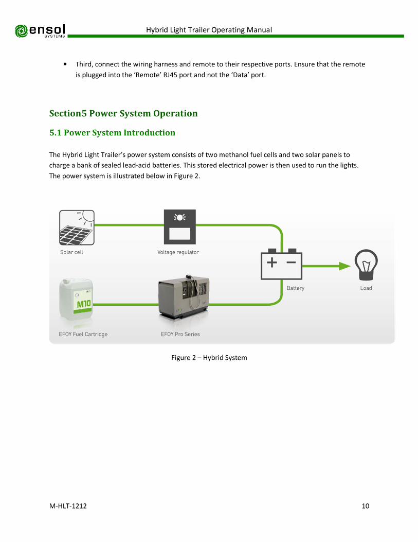
The Hybrid Light Trailer’s power system consists of two methanol fuel cells and two solar panels to
charge a bank of sealed lead-acid batteries. This stored electrical power is then used to run the lights.
The power system is illustrated below in Figure 2.
Figure 2 – Hybrid System
Hybrid Light Trailer Operating Manual
M-HLT-1212 11
5.2 Solar System Operation
The solar system is comprised of two 130Watt solar panels. If possible, try to face the panels south
towards the sun. Since the panels are on the mast, the lighting system may need to be located on the
south side of the area desired to be lit, in order to have the panels face south.
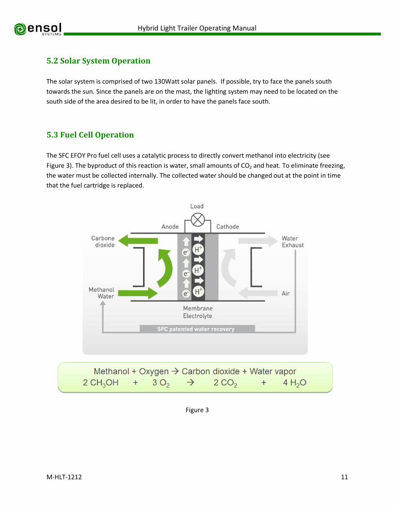
5.3 Fuel Cell Operation
The SFC EFOY Pro fuel cell uses a catalytic process to directly convert methanol into electricity (see
Figure 3). The byproduct of this reaction is water, small amounts of CO2 and heat. To eliminate freezing,
the water must be collected internally. The collected water should be changed out at the point in time
that the fuel cartridge is replaced.
Figure 3

Hybrid Light Trailer Operating Manual
M-HLT-1212 12
Since the EFOY Pro fuel cell is a ‘smart’ fuel cell, charging and monitoring to the batteries is handled
automatically (example in Figure 4). With the remote which is included, the user can view the charging
mode, battery voltage, charging current, system operating hours and firmware version, and can also
change the charging mode. By pressing the power button on the remote, the user can turn the system
off, put it in automatic or turn the system on for one charge cycle.
Figure 4
Ensol Systems has pre-programmed the fuel cell’s parameters for the installation location. If charging
voltage set points need to be altered, please contact Ensol Systems.
For a full description of the EFOY Pro fuel cell’s operation, please see the manual provided by SFC’s
document 101123_UM_EFOY_Pro_GB_v02.
5.4 UN Certified Methanol Fuel Cartridges
The EFOY Pro uses special plastic fuel cartridges to facilitate ease of use and transport:
• The methanol fuel cartridges are UN certified containers certified for transport on cargo planes.
• The containers are spill resistant and designed to withstand significant impact force.
• Empty cartridges should be recycled.
• 28L cartridges are the largest available size and a cartridge adapter is required to use this
cartridge with the EFOY Pro fuel cell. DO NOT THROW AWAY THE CARTRIDGE ADAPTER!

Hybrid Light Trailer Operating Manual
M-HLT-1212 13
• The fuel cell methanol is ultrapure. Do not puncture the cartridge. To avoid contamination, do
not transfer residual methanol from an old cartridge to a new cartridge. DO NOT USE ANY
OTHER METHANOL SOURCE TO FUEL THE EFOY PRO! Impure/contaminated methanol will
severely degrade the performance and life of the EFOY and will VOID WARRANTY.
Hybrid Light Trailer Operating Manual
M-HLT-1212 14
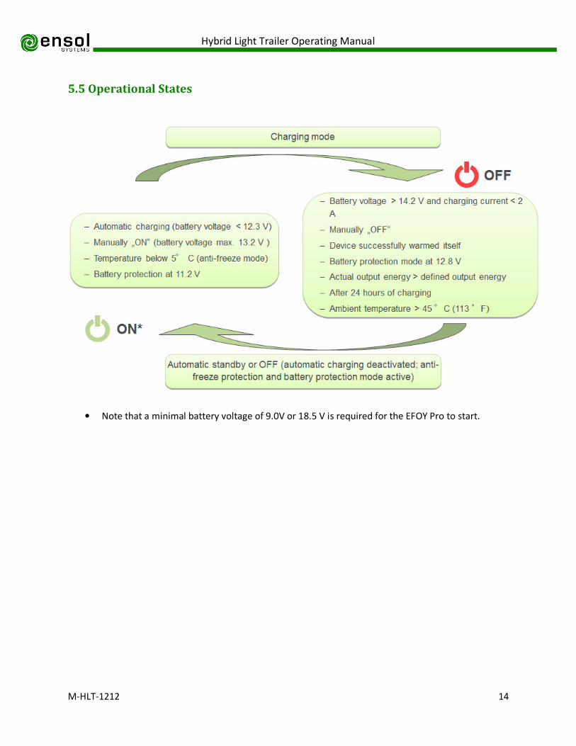
5.5 Operational States
• Note that a minimal battery voltage of 9.0V or 18.5 V is required for the EFOY Pro to start.
Hybrid Light Trailer Operating Manual
M-HLT-1212 15
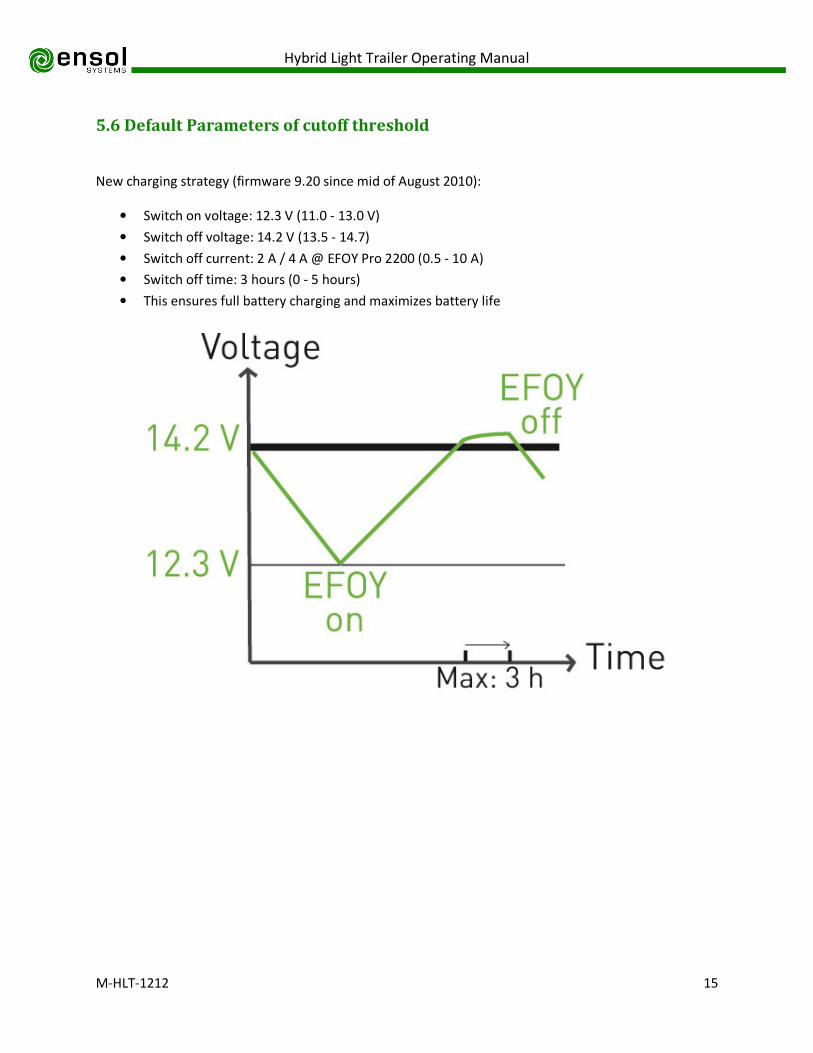
5.6 Default Parameters of cutoff threshold
New charging strategy (firmware 9.20 since mid of August 2010):
• Switch on voltage: 12.3 V (11.0 - 13.0 V)
• Switch off voltage: 14.2 V (13.5 - 14.7)
• Switch off current: 2 A / 4 A @ EFOY Pro 2200 (0.5 - 10 A)
• Switch off time: 3 hours (0 - 5 hours)
• This ensures full battery charging and maximizes battery life

Hybrid Light Trailer Operating Manual
M-HLT-1212 16
5.7 Startup and Shutdown Phases
Hybrid Light Trailer Operating Manual
M-HLT-1212 17
5.8 Anti–Freeze Protection Mode
• Note that the Hybrid Light Trailer is heavily insulated to ensure that the system works in cold
temperatures.
• THE ANTI-FREEZE PROTECTION MODE WILL NOT WORK WITHOUT FUEL! Please ensure that the
fuel cell does not run out of methanol in freezing temperatures. If the fuel cell freezes, 24 hours
will be required for the fuel cell to warm back up and be returned to service.
• The Anti-Freeze Mode will keep the EFOY Pro warm while the temperature is below 5oC (This
will work even when the unit is “OFF”).
• Anti-Freeze Mode requires the connection to a faultless, adequately charged battery and fuel
cartridge.
• Fuel consumption will be dependent upon external temperature differential. Weather,
insufficient insulation, ambient temperature and operating mode can have an impact on fuel
consumption.
• The EFOY Pro does not give the produced energy to a fully charged battery in Anti-Freeze Mode.
Rather, the stack “burns” methanol and supplies the peripheries (pumps, etc…) to heat up the
system. The batteries will not be overcharged.
• Startup temperature (when the Anti-Freeze Mode has not been activated) is 5 oC.
Hybrid Light Trailer Operating Manual
M-HLT-1212 18
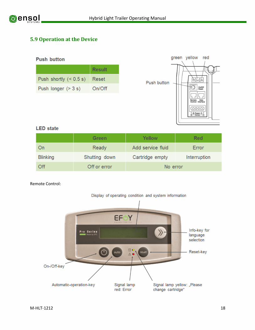
5.9 Operation at the Device
Remote Control:

Hybrid Light Trailer Operating Manual
M-HLT-1212 19
5.10 Service Fluid
• If service fluid is low the yellow light will turn on at the EFOY Pro and the message “Please refill
service fluid” will appear at the control panel display.
• Normally, there is no need to add service fluid prior to the initial start-up.
• Note that the fuel cell produces its own service fluid during operation. This is critical to the
function of the device. If the EFOY Pro is operated continuously at temperatures above the
acceptable operating range (45 oC), the service fluid will be expelled faster than it can be
regenerated and cause a failure. For this reason, it is critical that the thermostat and fan
provided with the Fuel Cell Power Package are maintained in working order and set at an
appropriate temperature.
• Service fluid can be added by removing the exhaust line as pictured below.

Hybrid Light Trailer Operating Manual
M-HLT-1212 20
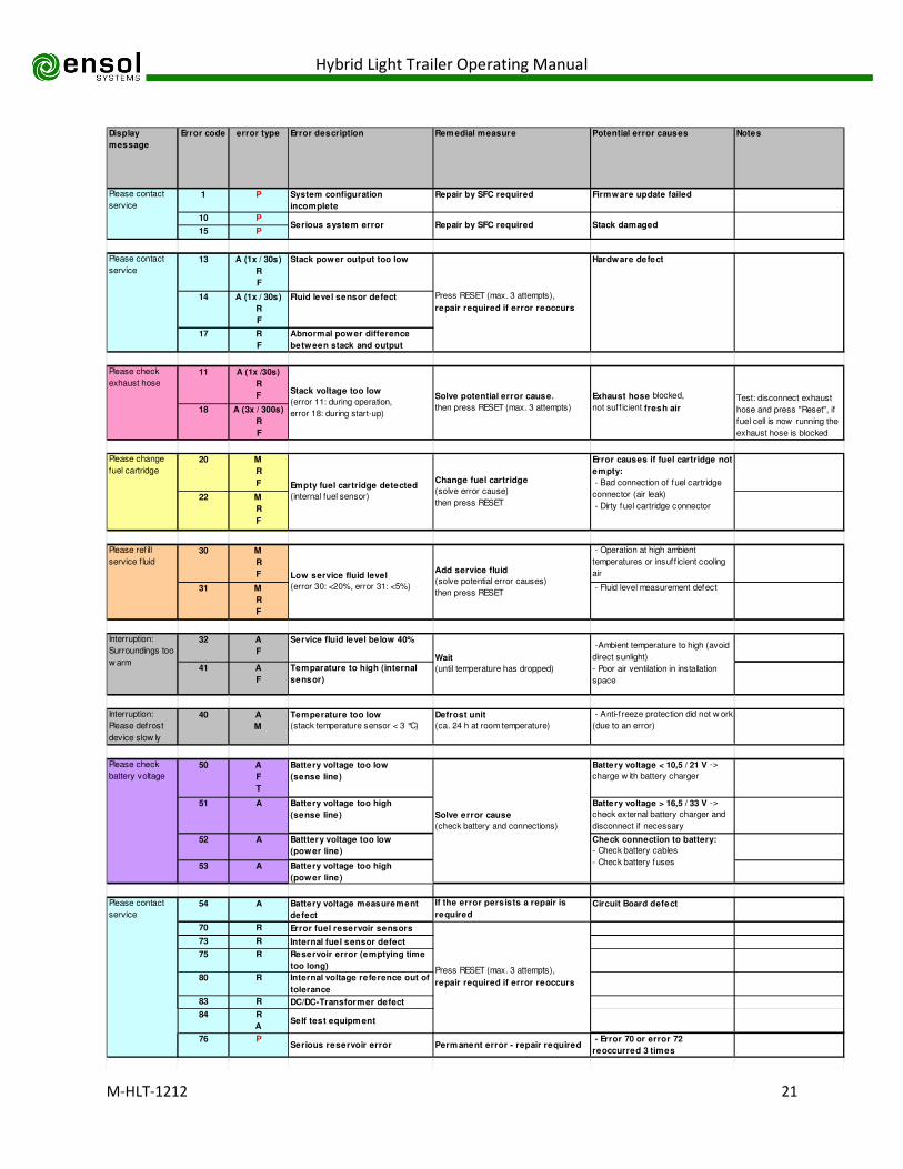
Section 6 Error Messages
6.1 Error Classifications Ranges
• 10 Internal hardware or firmware issue - Contact Ensol Systems.
• 20 Fuel - Change the cartridge and reset.
• 30 Service Fluid - Add service fluid and reset. Check thermostat and fan function.
• 40 Environmental Issue – Temperature too high or too low to maintain function.
• 50 Battery - Battery voltage too high or low. Check connections. Check solar charge controller.
• 70 Reservoir - Internal fuel problem. Check fuel connections and reset.
• 80 System - Internal voltage or system error. Reset.
6.2 Error Types
• A = Automatic reset (after error cause is remedied)
• M = Manual user intervention required
• F = Anti-freeze protection is possible from this error, if the error cause currently no longer exists
• P = Permanent error (not resettable)
• R = Reset required to restart system
• W = Warning
6.3 Most Common Error Messages
• 12, 13, 14 - Failure due to blocking of exhaust or circulation pump defect.
• 32, 31, 30, 41 - Failure due to high surrounding temperature. Check installation and ensure air
circulation is adequate.
• 52-54 - Check battery (voltage too low) and/or battery connection problem
• 72, 76 - Failure in Methanol dosing or internal sensors. Possible issues in Methanol cartridge
because of fuel line.
Hybrid Light Trailer Operating Manual
M-HLT-1212 21
Display
message
Error code error type Error description Remedial measure Potential error causes Notes
1 P System configuration
incomplete
Repair by SFC required Firmware update failed
10 P
15 P
13 A (1x / 30s)
R
F
Stack power output too low
14 A (1x / 30s)
R
F
Fluid level sensor defect
17 R
F
Abnormal power difference
between stack and output
11 A (1x /30s)
R
F
18 A (3x / 300s)
R
F
20 M
R
F
22 M
R
F
30 M
R
F
- Operation at high ambient
temperatures or insuff icient cooling
air
31 M
R
F
- Fluid level measurement defect
32 A
F
Service fluid level below 40%
41 A
F
Temparature to high (internal
sensor)
Interruption:
Please defrost
device slow ly
40 A
M
Temperature too low
(stack temperature sensor < 3 °C)
Defrost unit
(ca. 24 h at room temperature)
- Anti-freeze protection did not w ork
(due to an error)
50 A
F
T
Battery voltage too low
(sense line)
Battery voltage < 10,5 / 21 V ->
charge w ith battery charger
51 A Battery voltage too high
(sense line)
Battery voltage > 16,5 / 33 V ->
check external battery charger and
disconnect if necessary
52 A Batttery voltage too low
(power line)
53 A Battery voltage too high
(power line)
54 A Battery voltage measurement
defect
If the error persists a repair is
required
Circuit Board defect
70 R Error fuel reservoir sensors
73 R Internal fuel sensor defect
75 R Reservoir error (emptying time
too long)
80 R Internal voltage reference out of
tolerance
83 R DC/DC-Transformer defect
84 R
ASelf test equipment
76 PSerious reservoir error Permanent error - repair required
- Error 70 or error 72
reoccurred 3 times
Test: disconnect exhaust
hose and press "Reset", if
fuel cell is now running the
exhaust hose is blocked
Stack voltage too low
(error 11: during operation,
error 18: during start-up)
Solve potential error cause,
then press RESET (max. 3 attempts)
Exhaust hose blocked,
not suff icient fresh air
Please check
exhaust hose
Error causes if fuel cartridge not
empty:
- Bad connection of fuel cartridge
connector (air leak)
- Dirty fuel cartridge connector
Check connection to battery:
- Check battery cables
- Check battery fuses
Solve error cause
(check battery and connections)
Please change
fuel cartridge
Empty fuel cartridge detected
(internal fuel sensor)
Change fuel cartridge
(solve error cause)
then press RESET
Please ref ill
service f luid
Low service fluid level
(error 30: <20%, error 31: <5%)
-Ambient temperature to high (avoid
direct sunlight)
- Poor air ventilation in installation
space
Interruption:
Surroundings too
w armWait
(until temperature has dropped)
Serious system error
Please contact
service
Add service fluid
(solve potential error causes)
then press RESET
Repair by SFC required
Please check
battery voltage
Press RESET (max. 3 attempts),
repair required if error reoccurs
Stack damaged
Please contact
service
Please contact
service
Press RESET (max. 3 attempts),
repair required if error reoccurs
Hardware defect
Hybrid Light Trailer Operating Manual
M-HLT-1212 22
Please check fuel
cartridge
connector
72 A
M
F
R
Reservoir error (refilling time
too long)
Solve potential error cause,
then press RESET (max. 3 attempts)
- Firmware problem (FW <9.11)
- Bad connection of fuel cartridge
connector (pumps air)
- Dirty fuel cartridge connector
Firmw are update
recommended (f ixed w ith
FW 9.11 or higher)
Please install
Filter XT
38 W Filter EFOY XT is removed install Filter only EFOY 2200 XT
Please contact
service
85 R Filter-Circuit-Board EFOY XT not
detected
Press RESET (max. 3 attempts),
repair required if error reoccurs
only EFOY 2200 XT
no display
information
137 A Filter change confirmed no action required only EFOY 2200 XT
Please change
Filter XT
139 M Filter change is displayed change Filter EFOY XT only EFOY 2200 XT
no display
information
90 A Antifreezemode successfully no action required
Update: DO NOT
UNPLUG
BATTERY
99 A Firmware update is performed not interrupt firmware update
no display
information
140 AAntifreezemode not possible fix other error
another error is blocking the
antifreezemode
no display
information
172 AError 72 was once ignored
no action required
no display
information
184 A Self test equipment
successfully
no action required
Firmw are corrupt
update required
w ithout Atransfer defective firmware repeate firmware-update
- Remote control is connected to
w rong port (Data Interface)
- Batter voltage < 8,5 V
- No communication (defect)
No connect or
Check battery
w ithout Remote control has no
connection to fuel cell
Check connection, load battery if
necessary


![Home [] · Testimonials Trailer Delivery Horse Trailer Blog Horse Trailer Buying Guide Horse Trailer Lingo Horse Trailer Maintenance Trailering Safety Search Inventory OR enter Trailer#:](https://static.fdocuments.in/doc/165x107/5f60b857e51db4230831ff65/home-testimonials-trailer-delivery-horse-trailer-blog-horse-trailer-buying-guide.jpg)