Hybrid IP-PBX KX-TDA50 - Telecomuserguides.com · Extension Cards KX-TDA5170 4-Port Hybrid...
144
Model No. KX-TDA50 Hybrid IP-PBX Installation Manual Thank you for purchasing a Panasonic Hybrid IP-PBX. Please read this manual carefully before using this product and save this manual for future use. KX-TDA50: PSMPR Software File Version 6.0000 or later Document Version: 2010-11 SD Logo is a trademark of SD-3C, LLC.
-
Upload
vuongtuong -
Category
Documents
-
view
221 -
download
3
Transcript of Hybrid IP-PBX KX-TDA50 - Telecomuserguides.com · Extension Cards KX-TDA5170 4-Port Hybrid...
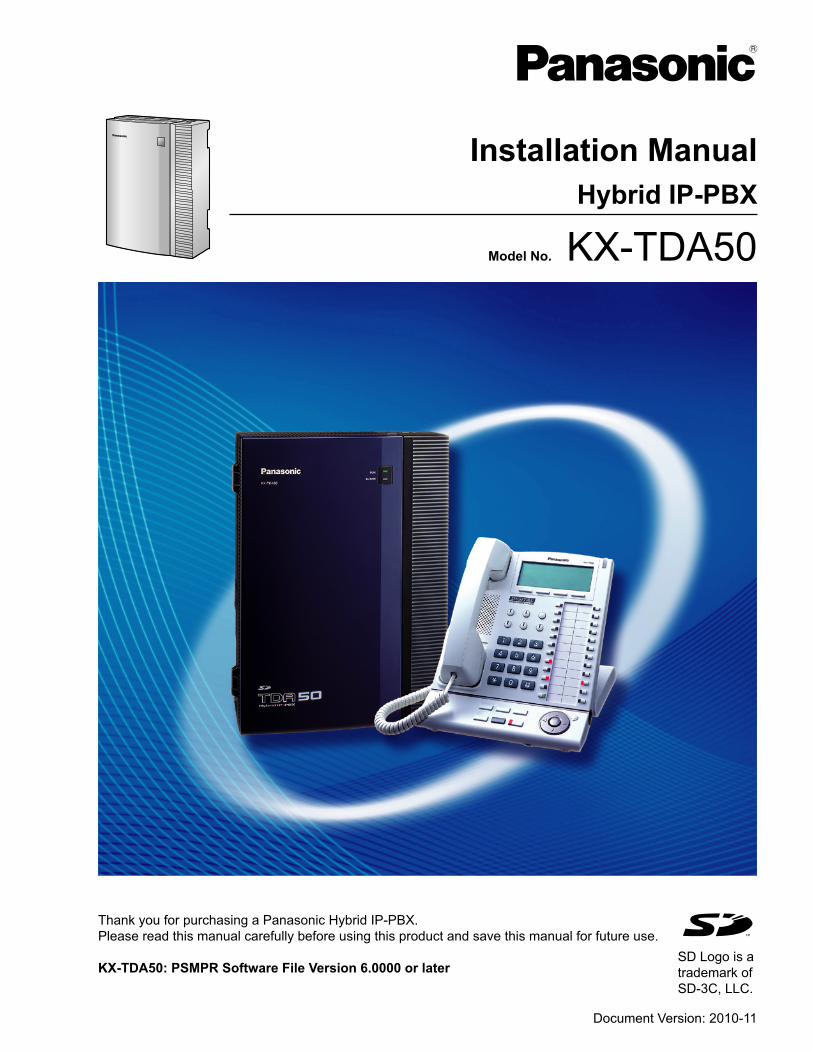
Model No. KX-TDA50
Hybrid IP-PBX
Installation Manual
Thank you for purchasing a Panasonic Hybrid IP-PBX.
Please read this manual carefully before using this product and save this manual for future use.
KX-TDA50: PSMPR Software File Version 6.0000 or later
Document Version: 2010-11
SD Logo is a
trademark of
SD-3C, LLC.
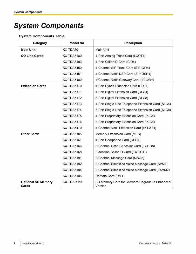
System ComponentsSystem Components Table
Category Model No. Description
Main Unit KX-TDA50 Main Unit
CO Line Cards KX-TDA5180 4-Port Analog Trunk Card (LCOT4)
KX-TDA5193 4-Port Caller ID Card (CID4)
KX-TDA5450 4-Channel SIP Trunk Card (SIP-GW4)
KX-TDA5451 4-Channel VoIP DSP Card (SIP-DSP4)
KX-TDA5480 4-Channel VoIP Gateway Card (IP-GW4)
Extension Cards KX-TDA5170 4-Port Hybrid Extension Card (HLC4)
KX-TDA5171 4-Port Digital Extension Card (DLC4)
KX-TDA5172 8-Port Digital Extension Card (DLC8)
KX-TDA5173 4-Port Single Line Telephone Extension Card (SLC4)
KX-TDA5174 8-Port Single Line Telephone Extension Card (SLC8)
KX-TDA5175 4-Port Proprietary Extension Card (PLC4)
KX-TDA5176 8-Port Proprietary Extension Card (PLC8)
KX-TDA5470 4-Channel VoIP Extension Card (IP-EXT4)
Other Cards KX-TDA5105 Memory Expansion Card (MEC)
KX-TDA5161 4-Port Doorphone Card (DPH4)
KX-TDA5166 8-Channel Echo Canceller Card (ECHO8)
KX-TDA5168 Extension Caller ID Card (EXT-CID)
KX-TDA5191 2-Channel Message Card (MSG2)
KX-TDA5192 2-Channel Simplified Voice Message Card (SVM2)
KX-TDA5194 2-Channel Simplified Voice Message Card (ESVM2)
KX-TDA5196 Remote Card (RMT)
Optional SD MemoryCards
KX-TDA5920 SD Memory Card for Software Upgrade to EnhancedVersion
2 Installation Manual Document Version 2010-11
System Components
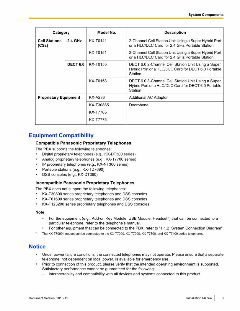
Category Model No. Description
Cell Stations(CSs)
2.4 GHz KX-T0141 2-Channel Cell Station Unit Using a Super Hybrid Portor a HLC/DLC Card for 2.4 GHz Portable Station
KX-T0151 2-Channel Cell Station Unit Using a Super Hybrid Portor a HLC/DLC Card for 2.4 GHz Portable Station
DECT 6.0 KX-T0155 DECT 6.0 2-Channel Cell Station Unit Using a SuperHybrid Port or a HLC/DLC Card for DECT 6.0 PortableStation
KX-T0158 DECT 6.0 8-Channel Cell Station Unit Using a SuperHybrid Port or a HLC/DLC Card for DECT 6.0 PortableStation
Proprietary Equipment KX-A236 Additional AC Adaptor
KX-T30865 Doorphone
KX-T7765
KX-T7775
Equipment CompatibilityCompatible Panasonic Proprietary TelephonesThe PBX supports the following telephones:• Digital proprietary telephones (e.g., KX-DT300 series)• Analog proprietary telephones (e.g., KX-T7700 series)• IP proprietary telephones (e.g., KX-NT300 series)• Portable stations (e.g., KX-TD7690)• DSS consoles (e.g., KX-DT390)
Incompatible Panasonic Proprietary TelephonesThe PBX does not support the following telephones:• KX-T30800 series proprietary telephones and DSS consoles• KX-T61600 series proprietary telephones and DSS consoles• KX-T123200 series proprietary telephones and DSS consoles
Note• For the equipment (e.g., Add-on Key Module, USB Module, Headset*1) that can be connected to a
particular telephone, refer to the telephone’s manual.• For other equipment that can be connected to the PBX, refer to "1.1.2 System Connection Diagram".
*1 The KX-T7090 headset can be connected to the KX-T7000, KX-T7200, KX-T7300, and KX-T7400 series telephones.
Notice• Under power failure conditions, the connected telephones may not operate. Please ensure that a separate
telephone, not dependent on local power, is available for emergency use.• Prior to connection of this product, please verify that the intended operating environment is supported.
Satisfactory performance cannot be guaranteed for the following:– interoperability and compatibility with all devices and systems connected to this product
Document Version 2010-11 Installation Manual 3
System Components
– proper operation and compatibility with services provided by telecommunications companies overconnected networks
NoteIn this manual, the suffix of each model number (e.g., KX-TDA50G) is omitted unless necessary.
Safety NoticesPlease observe the safety notices in this manual in order to avoid danger to users or other people, and preventdamage to property.The notices are classified as follows, according to the severity of injury or damage:
WARNING This notice means that misuse could result in death or serious injury.
CAUTION This notice means that misuse could result in injury or damage to property.
List of Abbreviations• APT ® Analog proprietary telephone• DPT ® Digital proprietary telephone• IP-PT ® IP proprietary telephone• PS ® Portable station• PT ® Proprietary telephone• SLT ® Single line telephone
4 Installation Manual Document Version 2010-11
System Components
Important Safety InstructionsWhen using your telephone equipment, basic safety precautions should always be followed to reduce the riskof fire, electric shock and injury to persons, including the following:• Do not use the product near water, for example, near a bathtub, wash bowl, kitchen sink, or laundry tub,
in a wet basement, or near a swimming pool.• Avoid using wired telephones during an electrical storm. There is a remote risk of electric shock from
lightning.• Do not use a telephone in the vicinity of a gas leak to report the leak.
SAVE THESE INSTRUCTIONS
Document Version 2010-11 Installation Manual 5
Important Safety Instructions
Important InformationSAVE THESE INSTRUCTIONS
WARNING
SAFETY REQUIREMENTSFor All Telephone Equipment• Do not install the product in any other way than described in relevant manuals.• The product must only be installed and serviced by qualified service personnel. The product should be
used as-is from the time of purchase; it should not be disassembled or modified. Disassembly ormodification can cause a fire, electric shock, or damage to the product.
• Do not install the product in a place exposed to rain or moisture, or a place where water, oil, or other liquidscan drip or splash onto on the product. Such conditions can lead to fire or electric shock, and may impairthe performance of the product.
• Follow all warnings and instructions marked on the product.• Do not place the product on an unstable or uneven surface. If the product were to fall over, it may cause
injury or damage to the product.• Products that require a power source should only be connected to the type of electrical power supply
specified on the product label. If you are not sure of the type of power supply to your home, consult yourdealer or local power company.
• For safety purposes some products are equipped with a grounded plug. If you do not have a groundedoutlet, please have one installed. Do not bypass this safety feature by tampering with the plug.
• Do not supply power to a combination of devices that exceeds the total rated capacity of the wall outletsor extension cables used. If outlets, power strips, extension cords, etc. are used in a manner that exceedstheir rated capacity, they emit large amounts of heat, which could cause a fire.
• Unplug the product from the wall outlet and have it serviced by qualified service personnel in the followingcases:a. When the power supply cord or plug is damaged or frayed.b. If liquid has been spilled into the product.c. If the product has been exposed to rain or water.d. If the product does not operate according to the operating instructions. Adjust only the controls that are
explained in the operating instructions. Improper adjustment of other controls may result in damageand may require service by a qualified technician to restore the product to normal operation.
e. If the product has been dropped or the cabinet has been damaged.f. If product performance deteriorates.
For the PBX• If damage to the unit exposes any internal parts, disconnect the power supply cord immediately and return
the unit to your dealer.• To prevent fires, electric shock, injury, or damage to the product, be sure to follow these guidelines when
performing any wiring or cabling:a. Before performing any wiring or cabling, unplug the product's power cord from the outlet. After
completing all wiring and cabling, plug the power cord back into the outlet.b. When laying cables, do not bundle the product's power cord with the power cords of other devices.c. Do not place any objects on top of the cables connected to the PBX.d. When running cables along the floor, use protectors to prevent the cables from being stepped on.e. Do not run any cables under carpeting.
6 Installation Manual Document Version 2010-11
Important Information
• Unplug this unit from the AC outlet if it emits smoke, an abnormal smell or makes unusual noise. Theseconditions can cause fire or electric shock. Confirm that smoke has stopped and contact an authorizedPanasonic Factory Service Center.
• Danger of explosion exists if a battery is incorrectly replaced. Replace only with the same or equivalenttype recommended by the battery manufacturer. Dispose of used batteries according to themanufacturer’s instructions.
• Make sure that the wall that the cabinet will be attached to is strong enough to support the cabinet. If not,it is necessary for the wall to be reinforced.
• Only use the wall-mounting equipment (screws, washers) included with the PBX.• Do not insert objects of any kind into this product, as they may touch dangerous voltage points or short out
parts that could result in a fire or electric shock.
CAUTION
SAFETY REQUIREMENTSFor All Telephone Equipment• The product should be kept free of dust, moisture, high temperature (more than 40 °C [104 °F]) and
vibration, and should not be exposed to direct sunlight.• Unplug the product from the wall outlet before cleaning. Wipe the product with a soft cloth. Do not clean
with abrasive powders or with chemical agents such as benzene or thinner. Do not use liquid cleaners oraerosol cleaners.
For the PBX• Before touching the product (PBX, cards, etc.), discharge static electricity by touching ground or wearing
a grounding strap. Failure to do so may cause the PBX to malfunction due to static electricity.• When driving the screws into the wall, be careful to avoid touching any metal laths, wire laths or metal
plates in the wall.• When relocating the equipment, first disconnect the telecom connection before disconnecting the power
connection. When the unit is installed in the new location, reconnect the power first, and then reconnectthe telecom connection.
• The power supply cord is used as the main disconnect device. Ensure that the AC outlet is located nearthe equipment and is easily accessible.
• The SD Memory Card poses a choking hazard. Keep the SD Memory Card out of reach of children.• Slots and openings in the front, back and bottom of the cabinet are provided for ventilation; to protect it
from overheating, these openings must not be blocked or covered. The openings should never be blockedby placing the product on a bed, sofa, rug, or other similar surface while in use. The product should neverbe placed near or over a radiator or other heat source. This product should not be placed in a sealedenvironment unless proper ventilation is provided.
• When this product is no longer in use, make sure to detach it from the wall.
SECURITY REQUIREMENTSIn order to use the PBX safely and correctly, the Security Requirements below must be observed. Failure todo so may result in:• Loss, leakage, falsification or theft of user information.• Illegal use of the PBX by a third party.• Interference or suspension of service caused by a third party.
What is User Information?User Information is defined as:
Document Version 2010-11 Installation Manual 7
Important Information
1. Information stored on the SD Memory CardPhonebook data, user IDs, system settings data, passwords (User/Administrator/Installer), PersonalIdentification Numbers (PINs), etc.
2. Information sent from the PBX to a PC or other external device:Phone call data (including telephone numbers of outside parties), call charge data, etc.
Requirements1. The SD Memory Card contains software for all the processes of the PBX and all customer data. It can be
easily removed and taken away from the PBX by a third party. Therefore, do not allow unauthorized accessto prevent data leakage.
2. Always make backups of data stored on the SD Memory Card. For details, refer to "2.6.2 Utility—FileTransfer PC to PBX (SD Card)" and "2.6.3 Utility—File Transfer PBX (SD Card) to PC" in the PCProgramming Manual.
3. To prevent illegal access from the Internet, activate a Firewall.4. To avoid unauthorized access and possible abuse of the PBX, we strongly recommend:
a. Keeping the password secret.b. Selecting a complex, random password that cannot be easily guessed.c. Changing your password regularly.
5. Perform the following when sending the PBX for repair or handing it over to a third party.a. Make a backup of data stored on the SD Memory Card.b. Using an SD formatter, format the SD Memory Card so that information cannot be retrieved from it.
6. To prevent data leakage, render the SD Memory Card physically unusable before disposal.7. When user information is sent from the PBX to a PC or other external device, the confidentiality of that
information becomes the responsibility of the customer. Before disposing of the PC or other external device,ensure that data cannot be retrieved from it by formatting the hard disk and/or rendering it physicallyunusable.
Notice
SAFETY REQUIREMENTSFor All Telephone Equipment• Read and understand all instructions.
For the PBX• Keep the unit away from heating appliances and devices that generate electrical noise such as fluorescent
lamps, motors and televisions. These noise sources can interfere with the performance of the PBX.• If you are having problems making calls to outside destinations, follow this procedure to test the CO lines:
a. Disconnect the PBX from all CO lines.b. Connect known working SLTs to those CO lines.c. Make a call to an external destination using those SLTs.If a call cannot be carried out correctly, there may be a problem with the CO line that the SLT is connectedto. Contact your telephone company.If all SLTs operate properly, there may be a problem with your PBX. Do not reconnect the PBX to the COlines until it has been serviced by an authorized Panasonic Factory Service Center.
8 Installation Manual Document Version 2010-11
Important Information
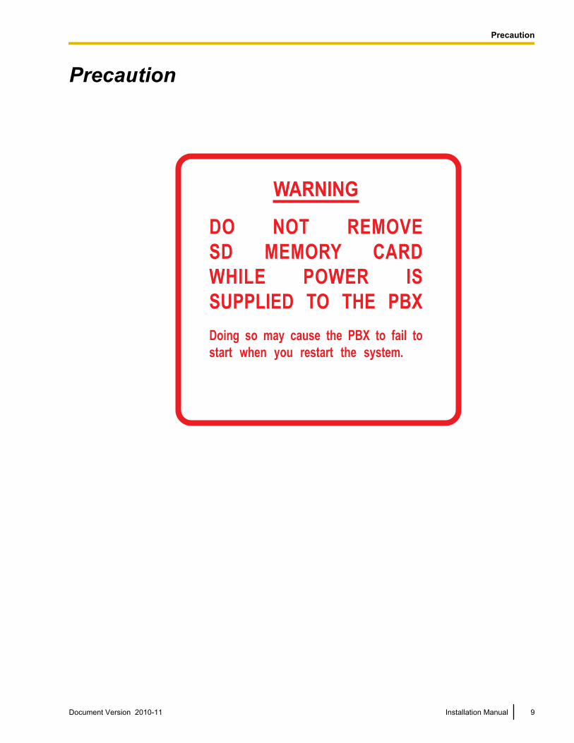
Precaution
WARNING
DO NOT REMOVE
SD MEMORY CARD
WHILE POWER IS
SUPPLIED TO THE PBX
Doing so may cause the PBX to fail to
start when you restart the system.
Document Version 2010-11 Installation Manual 9
Precaution
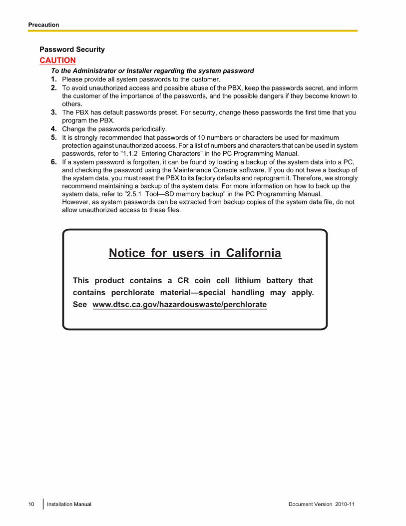
Password SecurityCAUTION
To the Administrator or Installer regarding the system password1. Please provide all system passwords to the customer.2. To avoid unauthorized access and possible abuse of the PBX, keep the passwords secret, and inform
the customer of the importance of the passwords, and the possible dangers if they become known toothers.
3. The PBX has default passwords preset. For security, change these passwords the first time that youprogram the PBX.
4. Change the passwords periodically.5. It is strongly recommended that passwords of 10 numbers or characters be used for maximum
protection against unauthorized access. For a list of numbers and characters that can be used in systempasswords, refer to "1.1.2 Entering Characters" in the PC Programming Manual.
6. If a system password is forgotten, it can be found by loading a backup of the system data into a PC,and checking the password using the Maintenance Console software. If you do not have a backup ofthe system data, you must reset the PBX to its factory defaults and reprogram it. Therefore, we stronglyrecommend maintaining a backup of the system data. For more information on how to back up thesystem data, refer to "2.5.1 Tool—SD memory backup" in the PC Programming Manual.However, as system passwords can be extracted from backup copies of the system data file, do notallow unauthorized access to these files.
Notice for users in California
This product contains a CR coin cell lithium battery that
contains perchlorate material—special handling may apply.
See www.dtsc.ca.gov/hazardouswaste/perchlorate
10 Installation Manual Document Version 2010-11
Precaution
IntroductionThis Installation Manual is designed to serve as an overall technical reference for the Panasonic HybridIP-PBX, KX-TDA50. It provides instructions for installing the hardware, and programming the PBX using theMaintenance Console.
The Structure of this ManualThis manual contains the following sections:Section 1 System OutlineProvides general information on the PBX, including the system capacity and specifications.Section 2 InstallationDescribes the procedures to install the PBX. Detailed instructions for planning the installation site, installingthe optional service cards, and cabling of peripheral equipment are provided. Further information on systemexpansion and peripheral equipment installation is included.Section 3 Guide for the PBX PC Programming SoftwareExplains the installation procedure, structure, and basic information of the Maintenance Console.Section 4 TroubleshootingProvides information on the PBX and telephone troubleshooting.
About the Other ManualsAlong with this Installation Manual, the following manuals are available:Feature ManualDescribes all basic, optional and programmable features of the PBX.PC Programming ManualProvides step-by-step instructions for performing system programming using a PC.PT Programming ManualProvides step-by-step instructions for performing system programming using a PT.Operating ManualProvides operating instructions for end users using a PT, SLT, PS, or DSS Console.
About the software version of your PBXThe contents of this manual apply to PBXs with a certain software version, as indicated on the cover of thismanual. To confirm the software version of your PBX, see "How do I confirm the software version of the PBXor installed cards?" in 2.7.1 Frequently Asked Questions (FAQ) of the PC Programming Manual, or "[190]Main Processing (MPR) Software Version Reference" in the PT Programming Manual.
Trademarks• The Bluetooth® word mark and logos are owned by the Bluetooth SIG, Inc. and any use of such marks by
Panasonic Corporation is under license.• Microsoft, Windows, and Windows Vista are either registered trademarks or trademarks of Microsoft
Corporation in the United States and/or other countries.• All other trademarks identified herein are the property of their respective owners.• Microsoft product screen shot(s) reprinted with permission from Microsoft Corporation.
Document Version 2010-11 Installation Manual 11
Introduction
F.C.C. REQUIREMENTS AND RELEVANTINFORMATION
1. Notification to the Telephone CompanyThis equipment complies with Part 68 of the FCC rules and the requirements adopted by the ACTA. Onthe side of this equipment is a label that contains, among other information, a product identifier in the formatUS: ACJMF03AKX-TDA50. If requested, this number must be provided to the telephone company.Installation must be performed by a qualified professional installer. If required, provide the telephonecompany with the following technical information:• Telephone numbers to which the system will be connected• Make: Panasonic• Model: KX-TDA50• Certification No.: found on the side of the unit• Ringer Equivalence No.: 0.3A• Facility Interface Code: 02LS2• Service Order Code: 9.0F• Required Network Interface Jack: RJ11
2. Ringer Equivalence Number (REN)The REN is used to determine the number of devices that may be connected to a telephone line. ExcessiveRENs on a telephone line may result in the devices not ringing in response to an incoming call. In mostbut not all areas, the sum of RENs should not exceed five (5.0). To be certain of the number of devicesthat may be connected to a line, as determined by the total RENs, contact the local telephone company.The REN for this product is part of the product identifier that has the format US: ACJMF03AKX-TDA50.The digits represented by 03 are the REN without a decimal point (e.g., 03 is a REN of 0.3). For earlierproducts, the REN is separately shown on the label.
3. Incidence of Harm to the Telephone LinesIf this equipment causes harm to the telephone network, the telephone company will notify you in advancethat temporary discontinuance of service may be required. But if advance notice isn’t practical, thetelephone company will notify the customer as soon as possible. Also, you will be advised of your right tofile a complaint with the FCC if you believe it is necessary.
4. Changes in Telephone Company Communications Facilities, Equipment, Operations andProceduresThe telephone company may make changes in its facilities, equipment, operations or procedures that couldaffect the operation of the equipment. If this happens the telephone company will provide advance noticein order for you to make necessary modifications to maintain uninterrupted service.
5. Trouble with this equipmentIf trouble is experienced with this equipment, for repair or warranty information, please see the attachedwarranty, which includes the Service Center Directory. If the equipment is causing harm to the telephonenetwork, the telephone company may request that you disconnect the equipment until the problem isresolved.
6. Connection to Party LineConnection to party line service is subject to state tariffs. Contact the state public utility commission, publicservice commission or corporation commission for information.
7. Combined Use with Alarm EquipmentIf your home has specially wired alarm equipment connected to the telephone line, ensure the installationof this equipment does not disable your alarm equipment. If you have questions about what will disablealarm equipment, consult your telephone company or a qualified installer.
NoteThis equipment has been tested and found to comply with the limits for a Class B digital device, pursuantto Part 15 of the FCC Rules. These limits are designed to provide reasonable protection against harmful
12 Installation Manual Document Version 2010-11
F.C.C. REQUIREMENTS AND RELEVANT INFORMATION
interference in a residential installation. This equipment generates, uses, and can radiate radio frequencyenergy and, if not installed and used in accordance with the instructions, may cause harmful interferenceto radio communications. However, there is no guarantee that interference will not occur in a particularinstallation. If this equipment does cause harmful interference to radio or television reception, which canbe determined by turning the equipment off and on, the user is encouraged to try to correct the interferenceby one or more of the following measures:• Reorient or relocate the receiving antenna.• Increase the separation between the equipment and receiver.• Connect the equipment into an outlet on a circuit different from that to which the receiver is connected.• Consult the dealer or an experienced radio/TV technician for help.
CAUTION• Any changes or modifications not expressly approved by the party responsible for compliance could
void the user’s authority to operate this device.• When programming emergency numbers and/or making test calls to emergency numbers:
1. Remain on the line and briefly explain to the dispatcher the reason for the call before hanging up.2. Perform such activities in the off-peak hours, such as early morning hours or late evenings.
• The software contained in the ARS and TRS features to allow user access to the network must beupgraded to recognize newly established network area codes and exchange codes as they are placedinto service. Failure to upgrade the premises PBXs or peripheral equipment to recognize the new codesas they are established will restrict the customer and the customer’s employees from gaining accessto the network and to these codes.KEEP THE SOFTWARE UP-TO-DATE WITH THE LATEST DATA.
Document Version 2010-11 Installation Manual 13
F.C.C. REQUIREMENTS AND RELEVANT INFORMATION
Table of Contents1 System Outline .......................................................................................171.1 Basic System Construction ...........................................................................................181.1.1 Main Unit ........................................................................................................................181.1.2 System Connection Diagram ..........................................................................................191.2 Optional Equipment ........................................................................................................211.2.1 Optional Equipment ........................................................................................................211.3 Specifications ..................................................................................................................231.3.1 General Description ........................................................................................................231.3.2 Characteristics ................................................................................................................251.3.3 System Capacity ............................................................................................................26
2 Installation ..............................................................................................312.1 Before Installation ...........................................................................................................322.1.1 Before Installation ...........................................................................................................322.2 Installation of the PBX ....................................................................................................342.2.1 Unpacking ......................................................................................................................342.2.2 Names and Locations .....................................................................................................352.2.3 Opening/Closing the Covers ..........................................................................................362.2.4 Installation of the SD Memory Card ...............................................................................392.2.5 Frame Ground Connection .............................................................................................412.2.6 Installing/Removing the Optional Service Cards ............................................................422.2.7 Types of Connectors ......................................................................................................532.2.8 Attaching a Ferrite Core .................................................................................................542.2.9 Wall Mounting (KX-TDA50) ............................................................................................552.2.10 Wall Mounting (AC Adaptor) ...........................................................................................582.2.11 Surge Protector Installation ............................................................................................622.3 Information about the CO Line Cards ...........................................................................652.3.1 LCOT4 Card (KX-TDA5180) ..........................................................................................652.3.2 CID4 Card (KX-TDA5193) ..............................................................................................662.3.3 IP-GW4 Card (KX-TDA5480) .........................................................................................672.3.4 SIP-GW4 Card (KX-TDA5450) .......................................................................................692.3.5 SIP-DSP4 Card (KX-TDA5451) ......................................................................................712.4 Information about the Extension Cards ........................................................................722.4.1 HLC4 Card (KX-TDA5170) .............................................................................................722.4.2 DLC4 Card (KX-TDA5171) .............................................................................................732.4.3 SLC4 Card (KX-TDA5173) .............................................................................................742.4.4 PLC4 Card (KX-TDA5175) .............................................................................................752.4.5 DLC8 Card (KX-TDA5172) .............................................................................................762.4.6 SLC8 Card (KX-TDA5174) .............................................................................................772.4.7 PLC8 Card (KX-TDA5176) .............................................................................................782.4.8 IP-EXT4 Card (KX-TDA5470) ........................................................................................792.5 Information about the Other Cards ...............................................................................812.5.1 DPH4 Card (KX-TDA5161) ............................................................................................812.5.2 ECHO8 Card (KX-TDA5166) ..........................................................................................842.5.3 MSG2 Card (KX-TDA5191) ............................................................................................852.5.4 SVM2 Card (KX-TDA5192) ............................................................................................862.5.5 ESVM2 Card (KX-TDA5194) ..........................................................................................872.5.6 EXT-CID Card (KX-TDA5168) ........................................................................................882.5.7 MEC Card (KX-TDA5105) ..............................................................................................892.5.8 RMT Card (KX-TDA5196) ..............................................................................................902.6 Connection of Extensions ..............................................................................................912.6.1 Maximum Cabling Distances of the Extension Wiring (Twisted Cable) ..........................91
14 Installation Manual Document Version 2010-11
Table of Contents
2.6.2 Parallel Connection of the Extensions ............................................................................932.6.3 Digital EXtra Device Port (Digital XDP) Connection .......................................................962.6.4 First Party Call Control CTI Connection .......................................................................1002.7 Connection of Doorphones, Door Openers, External Sensors, and External
Relays .............................................................................................................................1012.7.1 Connection of Doorphones, Door Openers, External Sensors, and External
Relays ..........................................................................................................................1012.8 Connection of Peripherals ...........................................................................................1052.8.1 Connection of Peripherals ............................................................................................1052.9 Power Failure Connections ..........................................................................................1092.9.1 Power Failure Connections ..........................................................................................1092.10 Starting the PBX ............................................................................................................1102.10.1 Starting the PBX ...........................................................................................................110
3 Guide for the PBX PC Programming Software ..................................1153.1 Overview ........................................................................................................................1163.1.1 Overview ......................................................................................................................1163.2 PC Connection ..............................................................................................................1173.2.1 PC Connection .............................................................................................................1173.3 Installation of the PBX PC Programming Software ...................................................1203.3.1 Installing and Starting the Maintenance Console .........................................................120
4 Troubleshooting ...................................................................................1234.1 Troubleshooting ............................................................................................................1244.1.1 Installation ....................................................................................................................1244.1.2 Connection ...................................................................................................................1264.1.3 Operation ......................................................................................................................1284.1.4 Using the Reset Button ................................................................................................1294.1.5 Troubleshooting by Error Log .......................................................................................130
5 Appendix ...............................................................................................1335.1 Revision History ............................................................................................................1345.1.1 PSMPR Software File Version 1.1xxx ..........................................................................1345.1.2 PSMPR Software File Version 2.0xxx ..........................................................................1355.1.3 PSMPR Software File Version 3.0xxx ..........................................................................1365.1.4 PSMPR Software File Version 4.0xxx ..........................................................................1375.1.5 PSMPR Software File Version 5.0xxx ..........................................................................138
Index............................................................................................................139
Document Version 2010-11 Installation Manual 15
Table of Contents

16 Installation Manual Document Version 2010-11
Table of Contents
Section 1
System Outline
This section provides general information on the PBX,including the system capacity and specifications.
Document Version 2010-11 Installation Manual 17
1.1 Basic System Construction
1.1.1 Main UnitThe main unit is equipped with 4 analog CO line ports (one LCOT4 card) and 4 extension ports (Super HybridPorts). For system expansion, optional service cards can be installed, and an additional AC adaptor can alsobe connected.
Construction of Main Unit
Main Board
LCOT4 card
(installed by default)
CID4 card
(installed by default)
Front Cover Cable Cover
NotePortions of this product contains software of Datalight, Inc. Copyright 1993–2000 Datalight,Inc., All RightsReserved.
18 Installation Manual Document Version 2010-11
1.1.1 Main Unit
1.1.2 System Connection Diagram
PC
Doorphone & Door Opener
BGM/Music On Hold (MOH)
Pager/
Speaker
Voice Processing
System
Remote PC
PC
Printer
CO (Telephone Company) Lines
Analog
PBX
SLT
Wireless Phone
Fax Machine
Amplifier
SLT
DPT
External Sensor/
External Relay Device
IP Softphone
CTI Server
PC
PC
IP-PT
Router
Private IP Network
ITSP*1
Network
DCE*2
(e.g., ADSL Modem)
PC
USB
KX-DT300 KX-DT300
KX-T7636/
KX-T7633
KX-DT346/
KX-DT343
PC
USB
KX-T7600 KX-T7600
APT DSS Console
DSS ConsoleDPT
PS CS
*1 ITSP: Internet Telephony Service Provider*2 DCE: Data Circuit Terminating Equipment
Document Version 2010-11 Installation Manual 19
1.1.2 System Connection Diagram
Station MessageDetail Recording (SMDR)
LCOT4*1
(KX-TDA5180)
MSG2(KX-TDA5191)
TelephoneCompany
PBX
Radio
AmplifierPager/Speaker
CID4*2
(KX-TDA5193)
4 Super Hybrid Ports*4
Main Board
AC Cord & AC Adaptor*3
AnalogCO Line
PCCTI Server
ECHO8(KX-TDA5166)
RMT(KX-TDA5196)
MEC(KX-TDA5105)
SLT WirelessPhone
Fax Machine
APT DPTDSS Console
PT-interface CS PSVoice
Processing
System
DSSConsoleDLC8
(KX-TDA5172)
DLC4(KX-TDA5171)
DPT
Voice Processing System
SVM2(KX-TDA5192)
DPH4(KX-TDA5161)
EXT-CID(KX-TDA5168)
Doorphone & Door OpenerExternal Sensor/External Relay Device
SLC8(KX-TDA5174)
SLC4(KX-TDA5173)
SLT Wireless Phone Fax Machine
DSS ConsoleAPT
Voice Processing System
LAN
IP-PT IP Softphone
IP-EXT4(KX-TDA5470)
Private IP Network
Router LAN
PC CTI Server
IP-GW4(KX-TDA5480)
SIP-DSP4(KX-TDA5451)
SIP-GW4(KX-TDA5450)
SLT Wireless Phone Fax Machine PT-interface CS PS
HLC4(KX-TDA5170)
DSS Console
Voice Processing System
APT
PC
LANITSP
Network
WAN
DCE(e.g., ADSL
Modem)
PLC8(KX-TDA5176)
PLC4(KX-TDA5175)
ESVM2(KX-TDA5194)
PCKX-DT346/KX-DT343/KX-T7636/KX-T7633 DPT
KX-DT300/KX-T7600DPT
KX-DT300/KX-T7600DPT
PC
KX-DT346/KX-DT343/KX-T7636/KX-T7633DPT
KX-DT300/KX-T7600DPT
KX-DT300/KX-T7600DPT
PSPT-interface CS
*1 One LCOT4 card is installed by default.*2 One CID4 card is installed by default.*3 In addition to the supplied AC adaptor, an additional AC adaptor can be connected to the PBX.*4 The PBX has 4 Super Hybrid Ports pre-installed.
20 Installation Manual Document Version 2010-11
1.1.2 System Connection Diagram
1.2 Optional Equipment
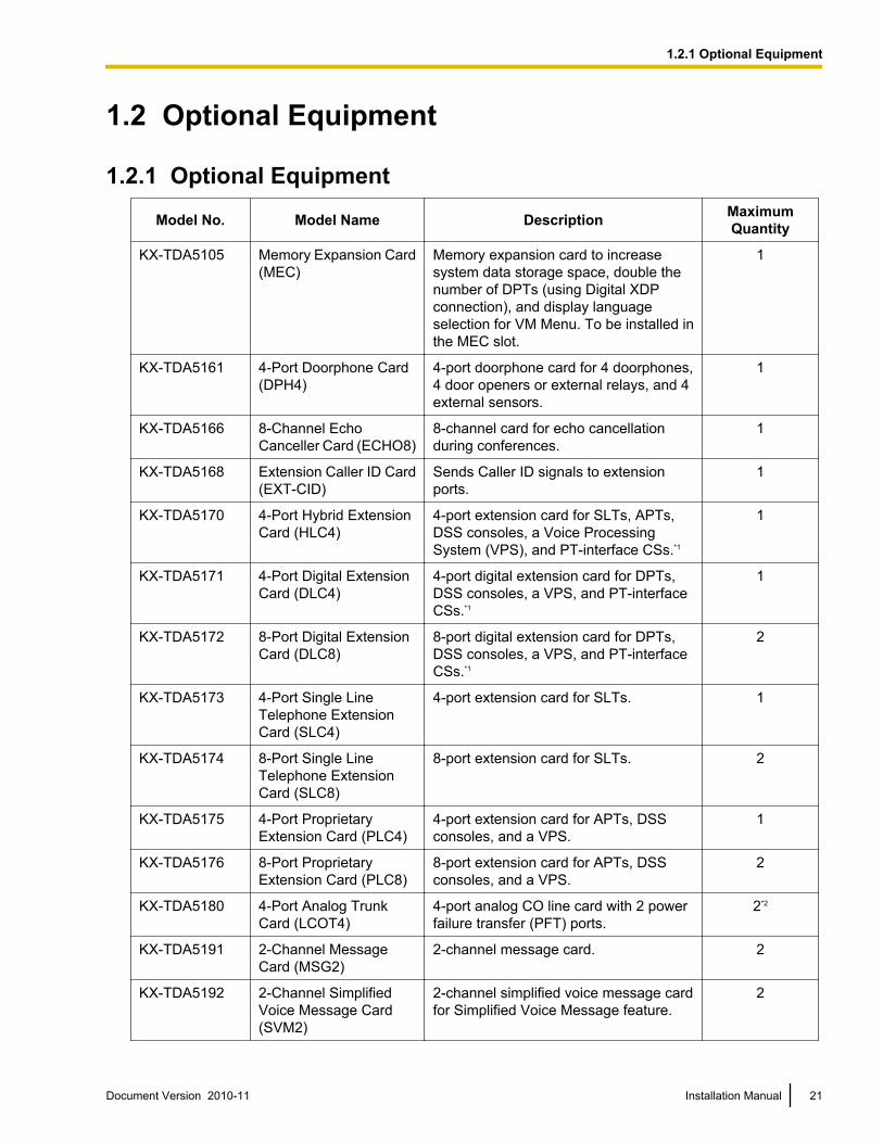
1.2.1 Optional Equipment
Model No. Model Name Description MaximumQuantity
KX-TDA5105 Memory Expansion Card(MEC)
Memory expansion card to increasesystem data storage space, double thenumber of DPTs (using Digital XDPconnection), and display languageselection for VM Menu. To be installed inthe MEC slot.
1
KX-TDA5161 4-Port Doorphone Card(DPH4)
4-port doorphone card for 4 doorphones,4 door openers or external relays, and 4external sensors.
1
KX-TDA5166 8-Channel EchoCanceller Card (ECHO8)
8-channel card for echo cancellationduring conferences.
1
KX-TDA5168 Extension Caller ID Card(EXT-CID)
Sends Caller ID signals to extensionports.
1
KX-TDA5170 4-Port Hybrid ExtensionCard (HLC4)
4-port extension card for SLTs, APTs,DSS consoles, a Voice ProcessingSystem (VPS), and PT-interface CSs.*1
1
KX-TDA5171 4-Port Digital ExtensionCard (DLC4)
4-port digital extension card for DPTs,DSS consoles, a VPS, and PT-interfaceCSs.*1
1
KX-TDA5172 8-Port Digital ExtensionCard (DLC8)
8-port digital extension card for DPTs,DSS consoles, a VPS, and PT-interfaceCSs.*1
2
KX-TDA5173 4-Port Single LineTelephone ExtensionCard (SLC4)
4-port extension card for SLTs. 1
KX-TDA5174 8-Port Single LineTelephone ExtensionCard (SLC8)
8-port extension card for SLTs. 2
KX-TDA5175 4-Port ProprietaryExtension Card (PLC4)
4-port extension card for APTs, DSSconsoles, and a VPS.
1
KX-TDA5176 8-Port ProprietaryExtension Card (PLC8)
8-port extension card for APTs, DSSconsoles, and a VPS.
2
KX-TDA5180 4-Port Analog TrunkCard (LCOT4)
4-port analog CO line card with 2 powerfailure transfer (PFT) ports.
2*2
KX-TDA5191 2-Channel MessageCard (MSG2)
2-channel message card. 2
KX-TDA5192 2-Channel SimplifiedVoice Message Card(SVM2)
2-channel simplified voice message cardfor Simplified Voice Message feature.
2
Document Version 2010-11 Installation Manual 21
1.2.1 Optional Equipment
Model No. Model Name Description MaximumQuantity
KX-TDA5193 4-Port Caller ID Card(CID4)
4-port Caller ID signal type FSK/FSK(with Call Waiting Caller ID [Visual CallerID])/DTMF. To be mounted on theLCOT4 card.
2*3
KX-TDA5194 2-Channel SimplifiedVoice Message Card(ESVM2)
2-channel simplified voice message cardfor Simplified Voice Message feature.Also supports MSG card features.
4
KX-TDA5196 Remote Card (RMT) Analog modem card for remotecommunication with the PBX. ITU-T V.90support.
1
KX-TDA5450 4-Channel SIP TrunkCard (SIP-GW4)
4-channel SIP gateway card. Compliantwith RFC 3261, 3262, 3264, 3311, and4028 protocols, and ITU-T G.729A/B andG.711 codec methods.
1
KX-TDA5451 4-Channel VoIP DSPCard (SIP-DSP4)
4-channel VoIP DSP card. To bemounted on the SIP-GW4 card.
1
KX-TDA5470 4-Channel VoIPExtension Card(IP-EXT4)
4-channel VoIP extension card.Compliant with Panasonic proprietaryprotocol, and ITU-T G.729A and G.711codec methods.
1
KX-TDA5480 4-Channel VoIPGateway Card (IP-GW4)
4-channel VoIP gateway card. This cardalso enables CTI communication andsystem programming via a LAN.Compliant with VoIP H.323 V.2 protocol,and ITU-T G.729A, G.723.1, and G.711codec methods. CSTA Phase 3 protocolcompatible.
1
KX-TDA5920 SD Memory Card forSoftware Upgrade toEnhanced Version
Optional SD Memory Card to useenhanced features. For more details,refer to the SD Memory Card Installation/Upgrade Guide.
1
KX-A236 Additional AC Adaptor AC adaptor and AC cord for systemexpansion.
1
*1 The PT-interface CS can be connected to the PBX using a cable like a PT.*2 One LCOT4 card is installed by default. Two more LCOT4 cards can be optionally installed in the PBX.*3 One CID4 card is installed by default. Two more CID4 cards can be optionally installed in the PBX.
22 Installation Manual Document Version 2010-11
1.2.1 Optional Equipment
1.3 Specifications
1.3.1 General DescriptionSwitching Non-blocking
AC Adaptor AC Input 110 V AC to 240 V AC; 1.35 A; 50 Hz/60 Hz
DC Output 40 V; 1.38 A (55.2 W)
DC Input • DC IN 1: 40 V; 1.38 A (55.2 W)• DC IN 2: 40 V; 1.38 A (55.2 W)
Maximum Power Failure Tolerance 300 ms
Memory Backup Duration 7 years
Dialing CO Line Dial Pulse (DP) 10 pps, 20 ppsTone (DTMF) Dialing
Extension Dial Pulse (DP) 10 pps, 20 ppsTone (DTMF) Dialing
Connectors CO Line RJ11 (2 wire) ´ each CO ports
Extension RJ11 (4 wire) ´ each extension ports
Paging Output 1 conductor jack
External MOH(Music on Hold)Output
1 conductor jack
Mode Conversion DP-DTMF, DTMF-DP
Ring Frequency 20 Hz/25 Hz (selectable)
Central Office Loop Limit 1600 W maximum
OperatingEnvironment
Temperature 0 °C to 40 °C (32 °F to 104 °F)
Humidity 10 % to 90 % (non-condensing)
Conference Call CO Line From 10 ´ 3-party conference call to 4 ´ 8-party conference call
Music on Hold 1 port (Level Control: -11 dB to +11 dB in 1 dB steps)Selectable Tone/External Music Source port
Paging Internal Level Control: -15 dB to +6 dB in 3 dB steps
External 1 port (Volume Control: -15 dB to +15 dB in 1 dB steps)
Serial InterfacePort
RS-232C 1 (maximum 115.2 kbps)
USB 1
Document Version 2010-11 Installation Manual 23
1.3.1 General Description
Extension Connection Cable SLT 1-pair wire (T, R)
DPT 1-pair wire (D1, D2) or2-pair wire (T, R, D1, D2)
APT 2-pair wire (T, R, D1, D2)
PT-interface CS (2-channel) 1-pair wire (D1, D2)
PT-interface CS (8-channel) 4-pair wire (D1, D2)
DSS Console and Add-on KeyModule
1-pair wire (D1, D2)
Dimension 275 mm (W) ´ 376 mm (H) ´ 117 mm (D)(10-4/5 in ´ 14-4/5 in ´ 4-3/5 in)
Weight (when fully mounted) Under 3.5 kg (7.72 lb)
24 Installation Manual Document Version 2010-11
1.3.1 General Description
1.3.2 CharacteristicsTerminal Equipment Loop Limit • PT: KX-DT300/KX-T7600 series DPT: 90 W; all other DPTs/APTs:
40 W• SLT: 600 W including set• Doorphone: 20 W• PT-interface CS: 65 W
Minimum Leakage Resistance 15 000 W minimum
Maximum Number of ExtensionInstruments per Line
1. for PT or SLT2. by Parallel or eXtra Device Port connection of a PT and an SLT3. by Digital eXtra Device Port connection of 2 DPTs and an SLT
Ring Voltage 75 Vrms at 20 Hz/25 Hz depending on the Ringing Load
Central Office Loop Limit 1600 W maximum
Hookswitch Flash Timing Range 24 ms to 2032 ms
Door Opener Current Limit 24 V DC/30 V AC, 1 A maximum
External Relay Current Limit 24 V DC/30 V AC, 1 A maximum
External Sensor Current Limit Power to the external sensor is provided from the DPH4 card and mustbe grounded through the DPH4 card. For the connection diagram,refer to "2.5.1 DPH4 Card (KX-TDA5161)". The PBX detects inputfrom the sensor when the signal is under 100 W.
Paging Terminal Impedance 600 W
MOH Terminal Impedance 10 000 W
Document Version 2010-11 Installation Manual 25
1.3.2 Characteristics
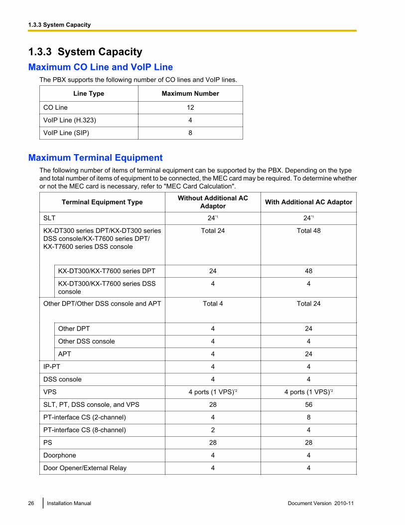
1.3.3 System CapacityMaximum CO Line and VoIP Line
The PBX supports the following number of CO lines and VoIP lines.
Line Type Maximum Number
CO Line 12
VoIP Line (H.323) 4
VoIP Line (SIP) 8
Maximum Terminal EquipmentThe following number of items of terminal equipment can be supported by the PBX. Depending on the typeand total number of items of equipment to be connected, the MEC card may be required. To determine whetheror not the MEC card is necessary, refer to "MEC Card Calculation".
Terminal Equipment Type Without Additional ACAdaptor With Additional AC Adaptor
SLT 24*1 24*1
KX-DT300 series DPT/KX-DT300 seriesDSS console/KX-T7600 series DPT/KX-T7600 series DSS console
Total 24 Total 48
KX-DT300/KX-T7600 series DPT 24 48
KX-DT300/KX-T7600 series DSSconsole
4 4
Other DPT/Other DSS console and APT Total 4 Total 24
Other DPT 4 24
Other DSS console 4 4
APT 4 24
IP-PT 4 4
DSS console 4 4
VPS 4 ports (1 VPS)*2 4 ports (1 VPS)*2
SLT, PT, DSS console, and VPS 28 56
PT-interface CS (2-channel) 4 8
PT-interface CS (8-channel) 2 4
PS 28 28
Doorphone 4 4
Door Opener/External Relay 4 4
26 Installation Manual Document Version 2010-11
1.3.3 System Capacity
Terminal Equipment Type Without Additional ACAdaptor With Additional AC Adaptor
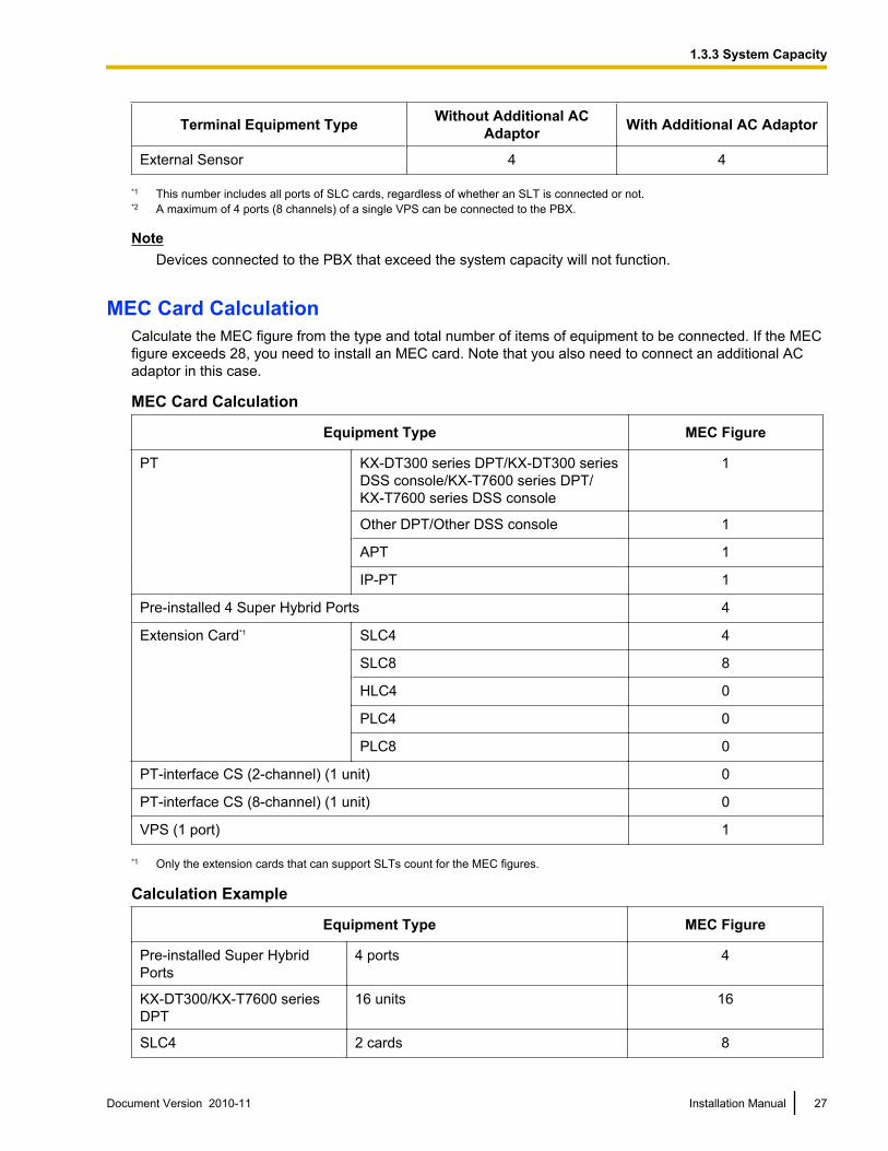
External Sensor 4 4
*1 This number includes all ports of SLC cards, regardless of whether an SLT is connected or not.*2 A maximum of 4 ports (8 channels) of a single VPS can be connected to the PBX.
NoteDevices connected to the PBX that exceed the system capacity will not function.
MEC Card CalculationCalculate the MEC figure from the type and total number of items of equipment to be connected. If the MECfigure exceeds 28, you need to install an MEC card. Note that you also need to connect an additional ACadaptor in this case.
MEC Card Calculation
Equipment Type MEC Figure
PT KX-DT300 series DPT/KX-DT300 seriesDSS console/KX-T7600 series DPT/KX-T7600 series DSS console
1
Other DPT/Other DSS console 1
APT 1
IP-PT 1
Pre-installed 4 Super Hybrid Ports 4
Extension Card*1 SLC4 4
SLC8 8
HLC4 0
PLC4 0
PLC8 0
PT-interface CS (2-channel) (1 unit) 0
PT-interface CS (8-channel) (1 unit) 0
VPS (1 port) 1
*1 Only the extension cards that can support SLTs count for the MEC figures.
Calculation Example
Equipment Type MEC Figure
Pre-installed Super HybridPorts
4 ports 4
KX-DT300/KX-T7600 seriesDPT
16 units 16
SLC4 2 cards 8
Document Version 2010-11 Installation Manual 27
1.3.3 System Capacity
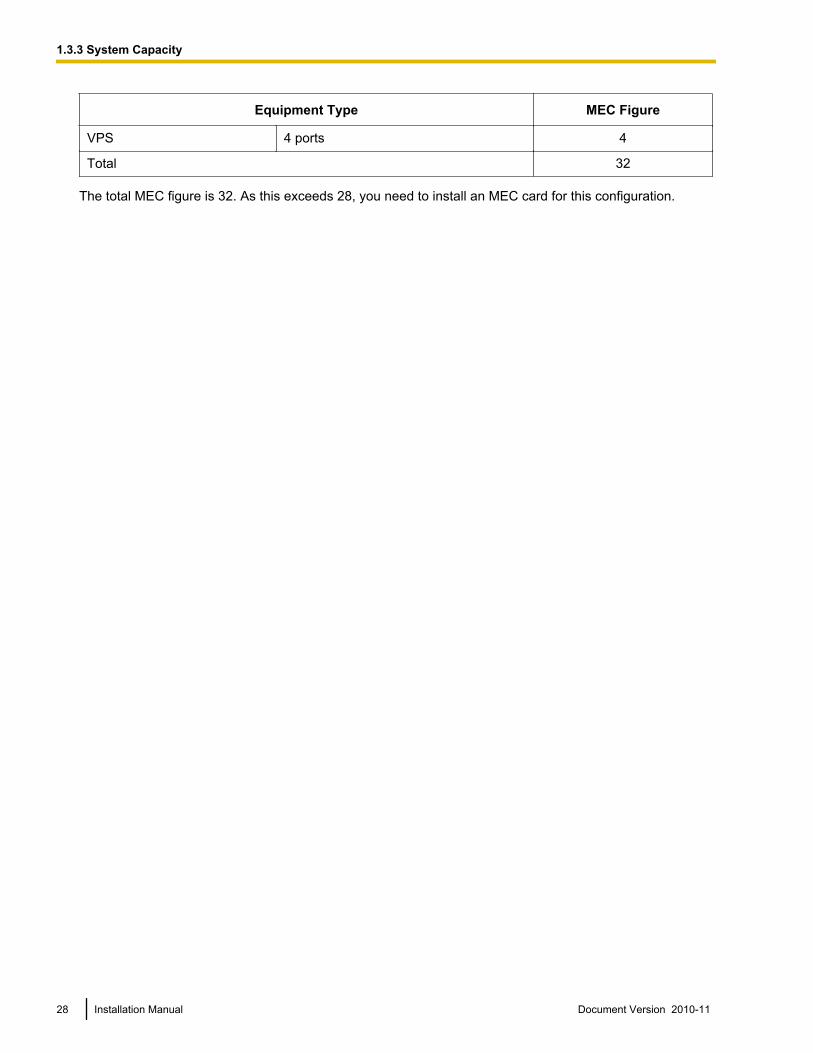
Equipment Type MEC Figure
VPS 4 ports 4
Total 32
The total MEC figure is 32. As this exceeds 28, you need to install an MEC card for this configuration.
28 Installation Manual Document Version 2010-11
1.3.3 System Capacity
AC Adaptor SelectionYou must connect an additional AC adaptor in any of the following conditions:• A total of more than 4 APTs, DPTs (except KX-DT300/KX-T7600 series), and DSS consoles (except
KX-DT300/KX-T7600 series) are connected.• More than 4 CSs are connected.• An MEC card is required to support a configuration with a total MEC figure exceeding 28.
NoteFor how to connect an AC adaptor or additional AC adaptor, refer to "2.10.1 Starting the PBX".
Document Version 2010-11 Installation Manual 29
1.3.3 System Capacity

30 Installation Manual Document Version 2010-11
1.3.3 System Capacity
Section 2
Installation
This section describes the procedures to install thePBX. Detailed instructions for planning the installationsite, installing the optional service cards, and cabling ofperipheral equipment are provided. Further informationon system expansion and peripheral equipmentinstallation is included.
Document Version 2010-11 Installation Manual 31
2.1 Before Installation
2.1.1 Before InstallationPlease read the following notes concerning installation and connection before installing the PBX and terminalequipment.Be sure to comply with all applicable laws, regulations, and guidelines.
Safety Installation InstructionsWARNING
When installing telephone wiring, basic safety precautions should always be followed to reducethe risk of fire, electric shock and injury to persons, including the following:
• Never install telephone wiring during a lightning storm.• Never install telephone jacks in wet locations unless the jack is specifically designed for wet
locations.• Never touch uninsulated telephone wires or terminals unless the telephone line has been
disconnected at the network interface.• Use caution when installing or modifying telephone lines.• Anti-static precautions should be taken during installation.
Installation PrecautionsThis PBX is designed for wall mounting only, and should be installed in a location where it is accessible forinspections and maintenance.To prevent malfunction, noise, or discoloration, follow the instructions below:
WARNINGDo not install the system in the following locations:• Areas where shocks or vibrations are frequent or strong. Such activity may lead to the product
falling over and causing injury, or may impair the product’s performance.• Areas with high amounts of dust. High amounts of dust can lead to fire or electric shock, and
impair the performance of the product.
CAUTIONDo not install the system in the following locations:• In direct sunlight and hot, cold, or humid places. Temperature range: 0 °C to 40 °C (32 °F to 104 °F)• Areas where sulfuric gases may be present, such as near thermal springs.• Near devices that generate high frequencies, such as sewing machines or electric welders.• Locations where other objects will obstruct the area around the PBX. Be especially careful to leave at
least 20 cm (8 in) of space above and 10 cm (4 in) to the sides of the PBX for ventilation.
NoticeDo not install the system in the following locations:• On or near computers, telexes, or other office equipment, as well as microwave ovens or air
conditioners. (It is preferable not to install the system in the same room as the above equipment.)• Within 1.8 m (6 ft) of radios and televisions. (Both the PBX and PTs should be at least 1.8 m (6 ft) away
from such devices).Do not perform the following:• Do not block the openings of the PBX.
32 Installation Manual Document Version 2010-11
2.1.1 Before Installation
• Do not stack up the optional service cards. To avoid damage to the optional service cards, always usethe extension bolts.
Wiring PrecautionsBe sure to follow these instructions when wiring the unit:
CAUTION• Avoid using the same AC outlet for computers, telexes, and other office equipment, as noise generated
by such equipment may hamper system performance or interrupt the system.• Unplug the system from its power source when wiring, and plug the system back in only after all wiring
is completed.• CO lines should be installed with surge protectors. For details, refer to "2.2.11 Surge Protector
Installation".
Notice• Use 2-pair telephone cables when connecting PTs.
Use 1-pair telephone cables when connecting SLTs, data terminals, answering machines, computers,Voice Processing Systems, etc.
• Mis-wiring may cause the PBX to operate improperly. Refer to "Section 2 Installation" when wiringthe system.
• If an extension does not operate properly, disconnect the telephone from the extension line and connectit again, or turn off the PBX using the power switch, then turn it on again.
• Use twisted pair cable for CO line connection.• To prevent signal noise from interfering with the performance of the product, do not run unshielded
telephone cables near AC power cables, computer cables, AC power sources, etc. When runningcables near other noise-generating devices or cables, use shielded telephone cables or shield thetelephone cables with metal tubing.
• To assure good quality telephone connection, it is recommended new and modifications to existinginstallation of customer premise wiring shall use solid twisted pair copper conductors with minimum 24gauge that comply with the electrical specifications for Category 3 wiring as detailed in ANSI/EIA/TIA-570A Building Wiring Standards.
Document Version 2010-11 Installation Manual 33
2.1.1 Before Installation
2.2 Installation of the PBX
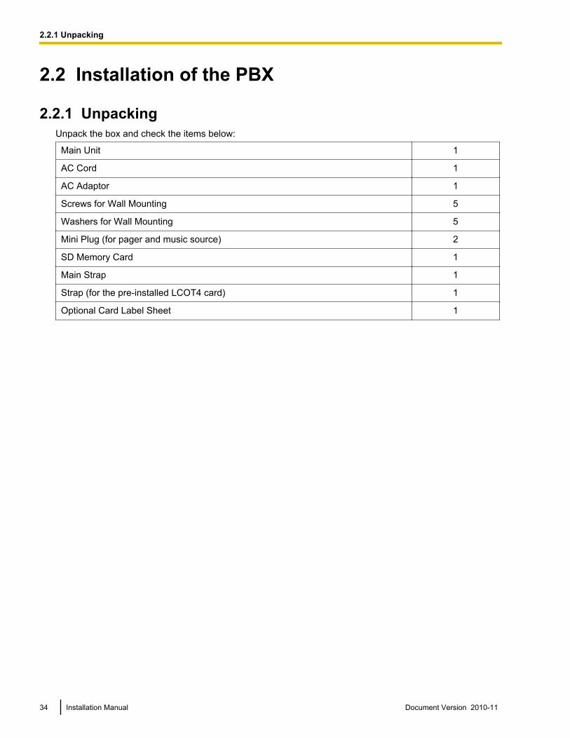
2.2.1 UnpackingUnpack the box and check the items below:
Main Unit 1
AC Cord 1
AC Adaptor 1
Screws for Wall Mounting 5
Washers for Wall Mounting 5
Mini Plug (for pager and music source) 2
SD Memory Card 1
Main Strap 1
Strap (for the pre-installed LCOT4 card) 1
Optional Card Label Sheet 1
34 Installation Manual Document Version 2010-11
2.2.1 Unpacking
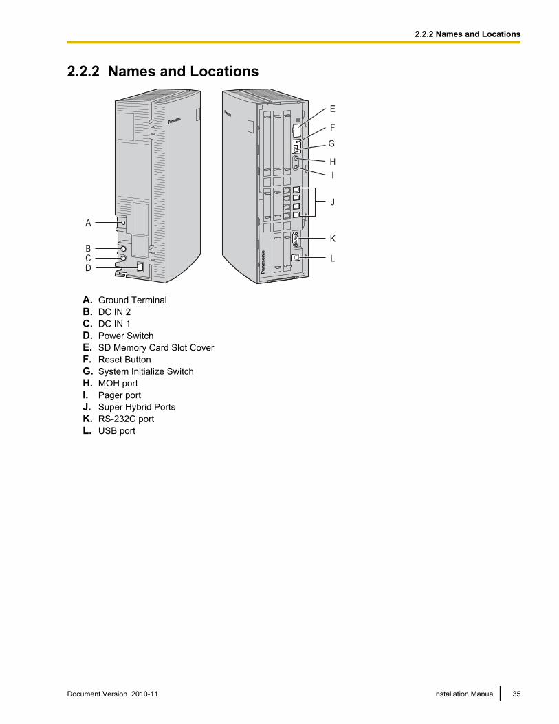
2.2.2 Names and Locations
E
F
H
I
J
K
L
G
B
C
A
D
A. Ground TerminalB. DC IN 2C. DC IN 1D. Power SwitchE. SD Memory Card Slot CoverF. Reset ButtonG. System Initialize SwitchH. MOH portI. Pager portJ. Super Hybrid PortsK. RS-232C portL. USB port
Document Version 2010-11 Installation Manual 35
2.2.2 Names and Locations
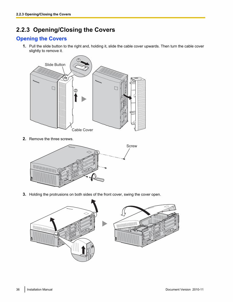
2.2.3 Opening/Closing the CoversOpening the Covers
1. Pull the slide button to the right and, holding it, slide the cable cover upwards. Then turn the cable coverslightly to remove it.
1
Slide Button
Cable Cover
2. Remove the three screws.
Screw
3. Holding the protrusions on both sides of the front cover, swing the cover open.
36 Installation Manual Document Version 2010-11
2.2.3 Opening/Closing the Covers
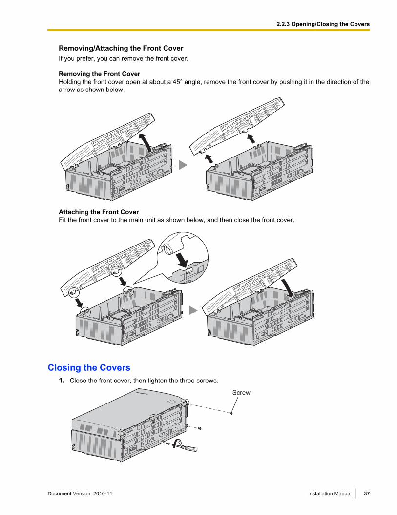
Removing/Attaching the Front CoverIf you prefer, you can remove the front cover.
Removing the Front CoverHolding the front cover open at about a 45° angle, remove the front cover by pushing it in the direction of thearrow as shown below.
Attaching the Front CoverFit the front cover to the main unit as shown below, and then close the front cover.
Closing the Covers1. Close the front cover, then tighten the three screws.
Screw
Document Version 2010-11 Installation Manual 37
2.2.3 Opening/Closing the Covers
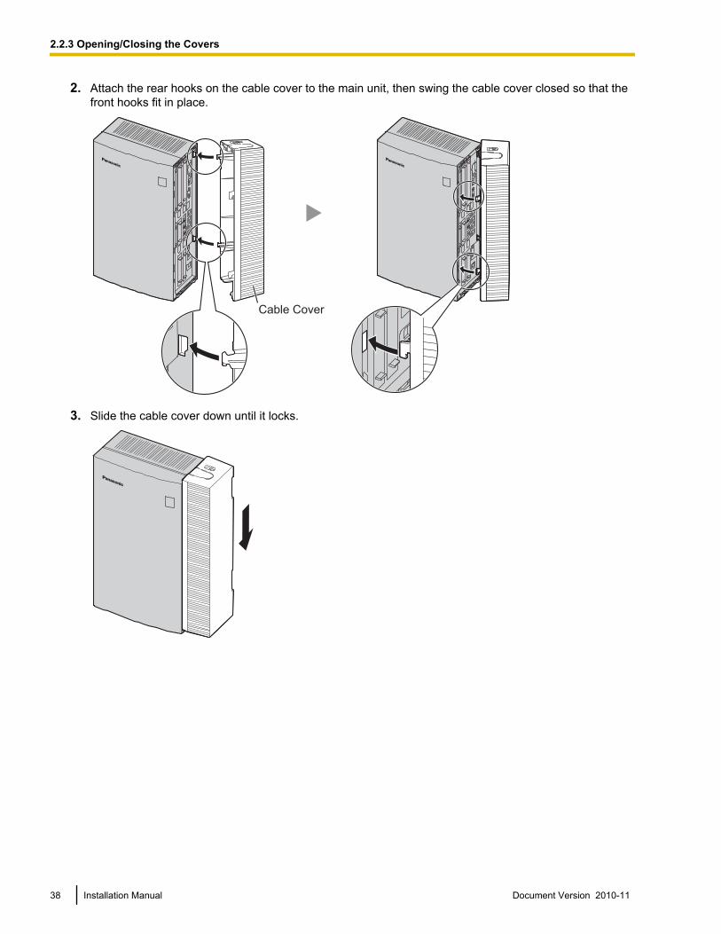
2. Attach the rear hooks on the cable cover to the main unit, then swing the cable cover closed so that thefront hooks fit in place.
Cable Cover
3. Slide the cable cover down until it locks.
38 Installation Manual Document Version 2010-11
2.2.3 Opening/Closing the Covers
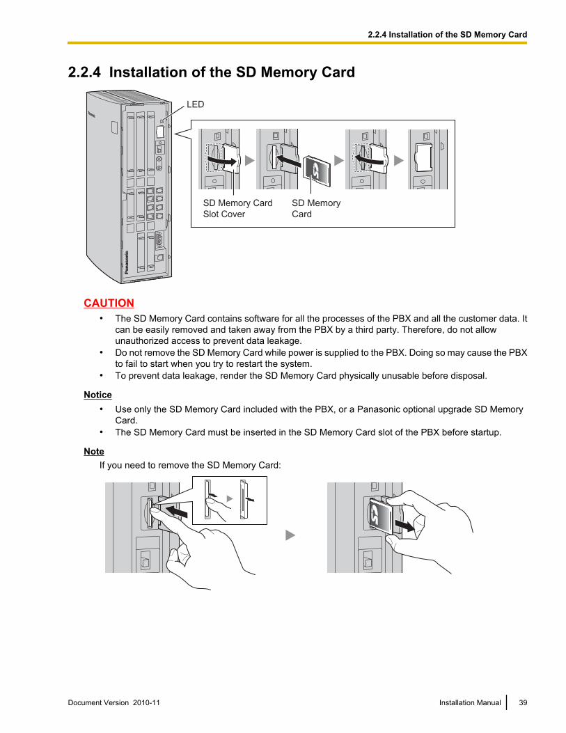
2.2.4 Installation of the SD Memory Card
SD Memory Card
Slot Cover
SD Memory
Card
LED
CAUTION• The SD Memory Card contains software for all the processes of the PBX and all the customer data. It
can be easily removed and taken away from the PBX by a third party. Therefore, do not allowunauthorized access to prevent data leakage.
• Do not remove the SD Memory Card while power is supplied to the PBX. Doing so may cause the PBXto fail to start when you try to restart the system.
• To prevent data leakage, render the SD Memory Card physically unusable before disposal.
Notice• Use only the SD Memory Card included with the PBX, or a Panasonic optional upgrade SD Memory
Card.• The SD Memory Card must be inserted in the SD Memory Card slot of the PBX before startup.
NoteIf you need to remove the SD Memory Card:
Document Version 2010-11 Installation Manual 39
2.2.4 Installation of the SD Memory Card
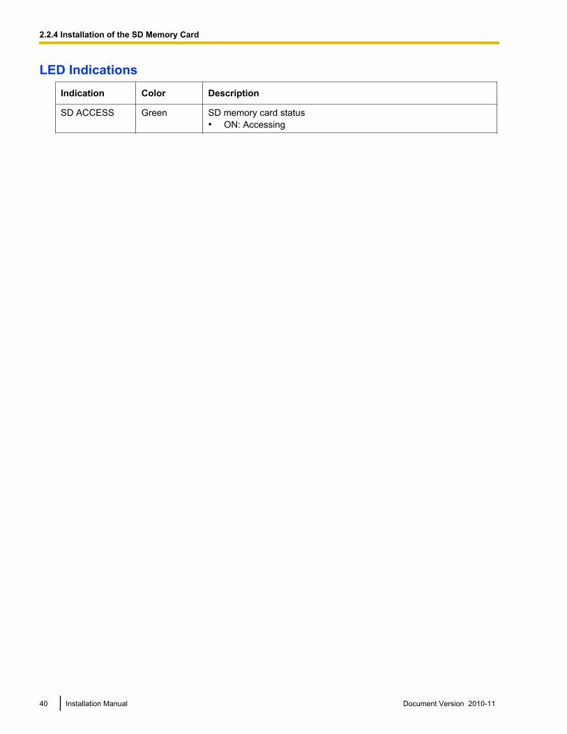
LED IndicationsIndication Color Description
SD ACCESS Green SD memory card status• ON: Accessing
40 Installation Manual Document Version 2010-11
2.2.4 Installation of the SD Memory Card
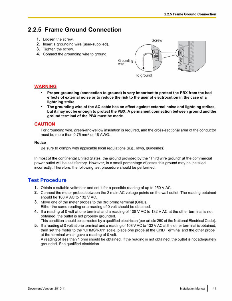
2.2.5 Frame Ground Connection1. Loosen the screw.2. Insert a grounding wire (user-supplied).3. Tighten the screw.4. Connect the grounding wire to ground.
Screw
Groundingwire
To ground
WARNING• Proper grounding (connection to ground) is very important to protect the PBX from the bad
effects of external noise or to reduce the risk to the user of electrocution in the case of alightning strike.
• The grounding wire of the AC cable has an effect against external noise and lightning strikes,but it may not be enough to protect the PBX. A permanent connection between ground and theground terminal of the PBX must be made.
CAUTIONFor grounding wire, green-and-yellow insulation is required, and the cross-sectional area of the conductormust be more than 0.75 mm2 or 18 AWG.
NoticeBe sure to comply with applicable local regulations (e.g., laws, guidelines).
In most of the continental United States, the ground provided by the “Third wire ground” at the commercialpower outlet will be satisfactory. However, in a small percentage of cases this ground may be installedincorrectly. Therefore, the following test procedure should be performed.
Test Procedure1. Obtain a suitable voltmeter and set it for a possible reading of up to 250 V AC.2. Connect the meter probes between the 2 main AC voltage points on the wall outlet. The reading obtained
should be 108 V AC to 132 V AC.3. Move one of the meter probes to the 3rd prong terminal (GND).
Either the same reading or a reading of 0 volt should be obtained.4. If a reading of 0 volt at one terminal and a reading of 108 V AC to 132 V AC at the other terminal is not
obtained, the outlet is not properly grounded.This condition should be corrected by a qualified electrician (per article 250 of the National Electrical Code).
5. If a reading of 0 volt at one terminal and a reading of 108 V AC to 132 V AC at the other terminal is obtained,then set the meter to the "OHMS/RX1" scale, place one probe at the GND Terminal and the other probeat the terminal which gave a reading of 0 volt.A reading of less than 1 ohm should be obtained. If the reading is not obtained, the outlet is not adequatelygrounded. See qualified electrician.
Document Version 2010-11 Installation Manual 41
2.2.5 Frame Ground Connection
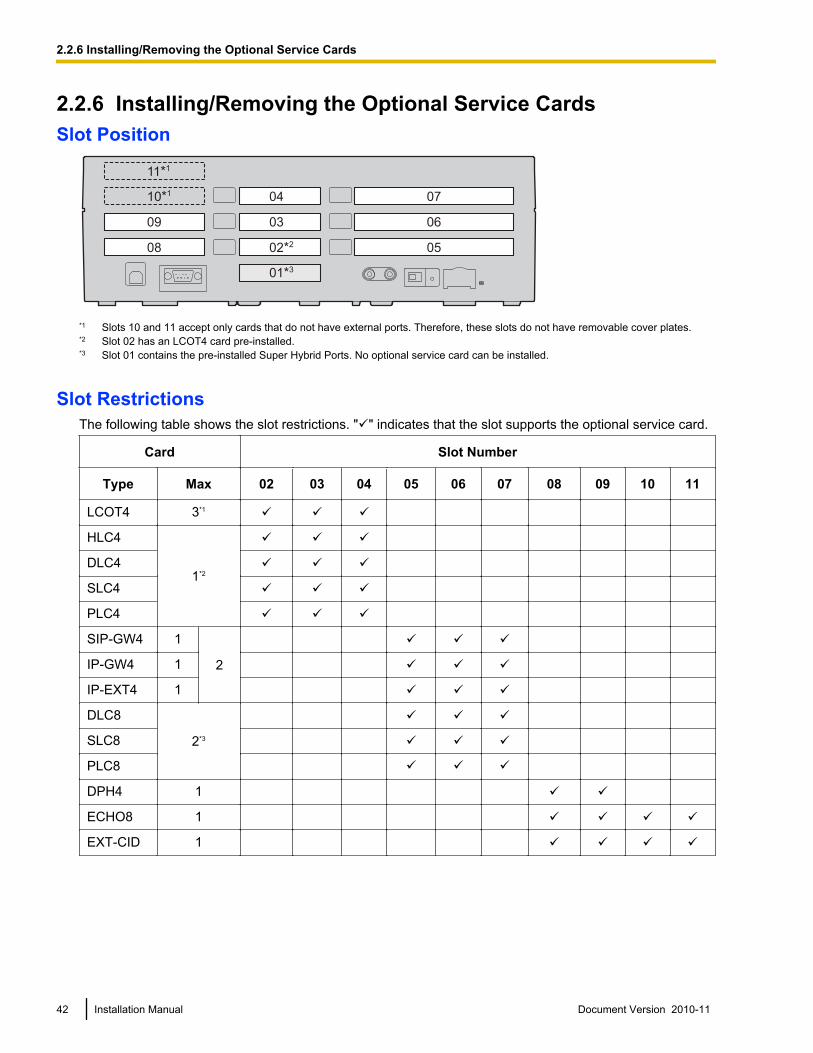
2.2.6 Installing/Removing the Optional Service CardsSlot Position
02*2
03
04
05
06
07
08
09
10*1
11*1
01*3
*1 Slots 10 and 11 accept only cards that do not have external ports. Therefore, these slots do not have removable cover plates.*2 Slot 02 has an LCOT4 card pre-installed.*3 Slot 01 contains the pre-installed Super Hybrid Ports. No optional service card can be installed.
Slot RestrictionsThe following table shows the slot restrictions. "ü" indicates that the slot supports the optional service card.
Card Slot Number
Type Max 02 03 04 05 06 07 08 09 10 11
LCOT4 3*1 ü ü ü
HLC4
1*2
ü ü ü
DLC4 ü ü ü
SLC4 ü ü ü
PLC4 ü ü ü
SIP-GW4 1
2
ü ü ü
IP-GW4 1 ü ü ü
IP-EXT4 1 ü ü ü
DLC8
2*3
ü ü ü
SLC8 ü ü ü
PLC8 ü ü ü
DPH4 1 ü ü
ECHO8 1 ü ü ü ü
EXT-CID 1 ü ü ü ü
42 Installation Manual Document Version 2010-11
2.2.6 Installing/Removing the Optional Service Cards
Card Slot Number
Type Max 02 03 04 05 06 07 08 09 10 11
MSG2 24
ü ü ü ü
SVM2 2 ü ü ü ü
ESVM2 4 ü ü ü ü
*1 Including one LCOT4 card that is installed by default.*2 Only one of the HLC4, DLC4, SLC4 or PLC4 card can be installed.*3 A maximum of two DLC8, SLC8 and PLC8 cards can be installed.
CAUTION• To protect the main board from static electricity, do not touch parts on the main board or on the optional
service cards. To discharge static electricity, touch ground or wear a grounding strap.• When installing or removing the optional service cards, the power switch of the PBX must be in the off
position.
Note• For each card, the maximum number that can be installed in the PBX is listed in "1.2.1 Optional
Equipment".• Any card that exceeds the capacity of the PBX will be ignored.• When the PBX starts up with an invalid configuration, some cards will be ignored.
Installing Optional Service Cards1. Before installing the optional service cards, cut and remove the appropriate dummy cover plates from the
main unit.
Dummy Cover Plate
CAUTIONFor safety reasons, smooth the cut edges after removing the dummy cover plates.
Document Version 2010-11 Installation Manual 43
2.2.6 Installing/Removing the Optional Service Cards
2. Position the card in the open slot, making sure that the tabs on the both sides of the card fit into place.Then, holding the card firmly in place, lower the rear end so that the hole of the card fits over the extensionbolt.
1
2
Extension Bolt
Optional Service Card
CAUTIONWhen installing the optional service cards, do not put pressure on any parts of the main board (e.g.,tall capacitors). Doing so may result in damage to the PBX.
3. Insert the new extension bolt (included with the card) into the hole on the card, and tighten it to secure thecard.
Extension Bolt
44 Installation Manual Document Version 2010-11
2.2.6 Installing/Removing the Optional Service Cards
4. Stick an appropriate optional card label (included) to the left side of the corresponding card.
Optional Card Label
5. Connect a cable to an appropriate port of the card.For details about pin assignments, refer to the appropriate section in "2.3 Information about the CO LineCards" and "2.4 Information about the Extension Cards".
NoteMake sure to connect cables after installing the card in the PBX, not before.
6. Repeat the procedure for other cards.A. When installing a card in Slot 07, make sure to detach the LED holder first. After installing the card,
reattach the LED holder.
Document Version 2010-11 Installation Manual 45
2.2.6 Installing/Removing the Optional Service Cards
To detach the LED holder
LED holder
To attach the LED holder
46 Installation Manual Document Version 2010-11
2.2.6 Installing/Removing the Optional Service Cards
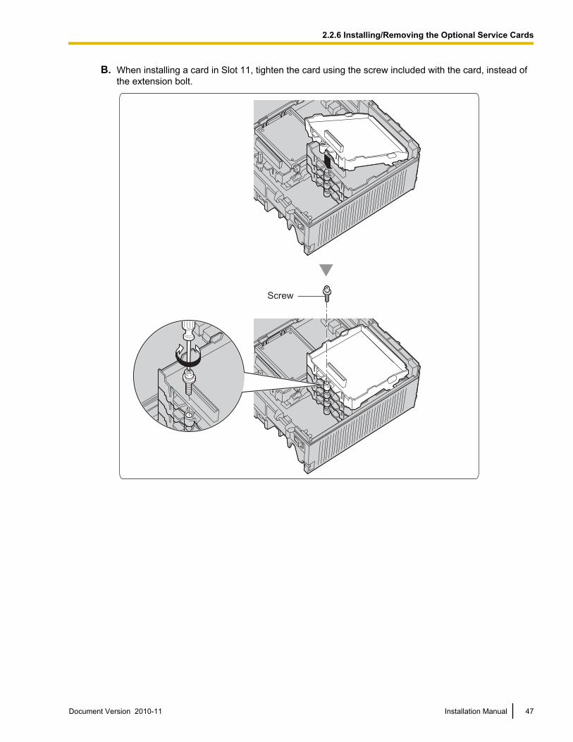
B. When installing a card in Slot 11, tighten the card using the screw included with the card, instead ofthe extension bolt.
Screw
Document Version 2010-11 Installation Manual 47
2.2.6 Installing/Removing the Optional Service Cards
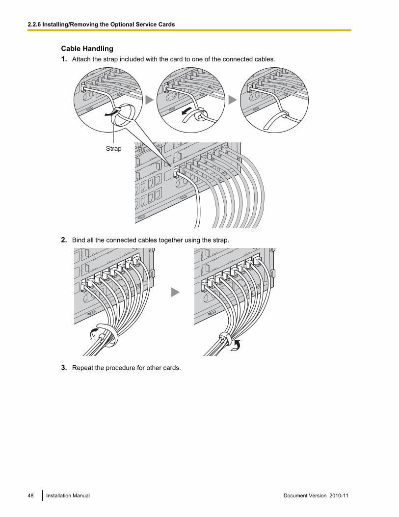
Cable Handling1. Attach the strap included with the card to one of the connected cables.
Strap
2. Bind all the connected cables together using the strap.
3. Repeat the procedure for other cards.
48 Installation Manual Document Version 2010-11
2.2.6 Installing/Removing the Optional Service Cards
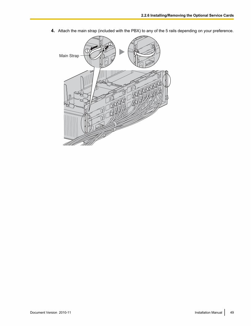
4. Attach the main strap (included with the PBX) to any of the 5 rails depending on your preference.
1
2
Main Strap
Document Version 2010-11 Installation Manual 49
2.2.6 Installing/Removing the Optional Service Cards
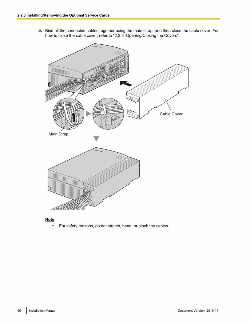
5. Bind all the connected cables together using the main strap, and then close the cable cover. Forhow to close the cable cover, refer to "2.2.3 Opening/Closing the Covers".
Cable Cover
Main Strap
Note• For safety reasons, do not stretch, bend, or pinch the cables.
50 Installation Manual Document Version 2010-11
2.2.6 Installing/Removing the Optional Service Cards
• If you prefer, you can cut the other side of the cable cover and run the cables through thatopening. For safety reasons, smooth the cut edges.
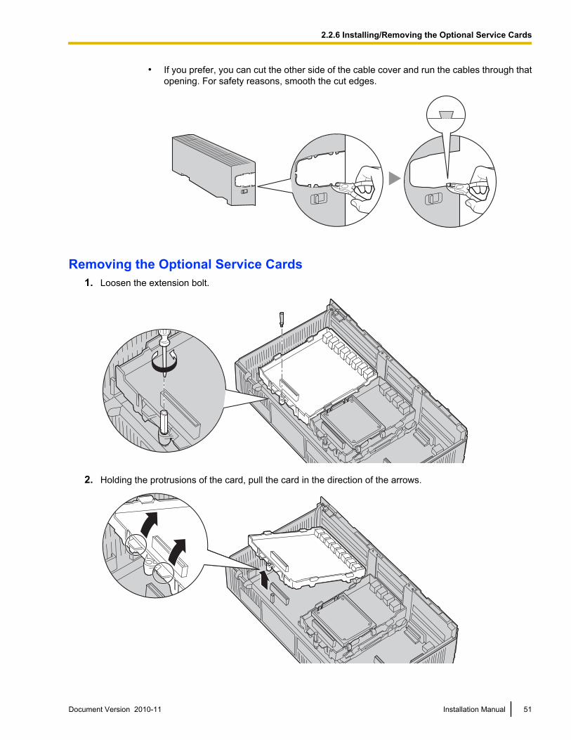
Removing the Optional Service Cards1. Loosen the extension bolt.
2. Holding the protrusions of the card, pull the card in the direction of the arrows.
Document Version 2010-11 Installation Manual 51
2.2.6 Installing/Removing the Optional Service Cards

CAUTIONWhen removing the optional service cards, do not put pressure on any parts of the main board (e.g.,tall capacitors). Doing so may result in damage to the PBX.
52 Installation Manual Document Version 2010-11
2.2.6 Installing/Removing the Optional Service Cards
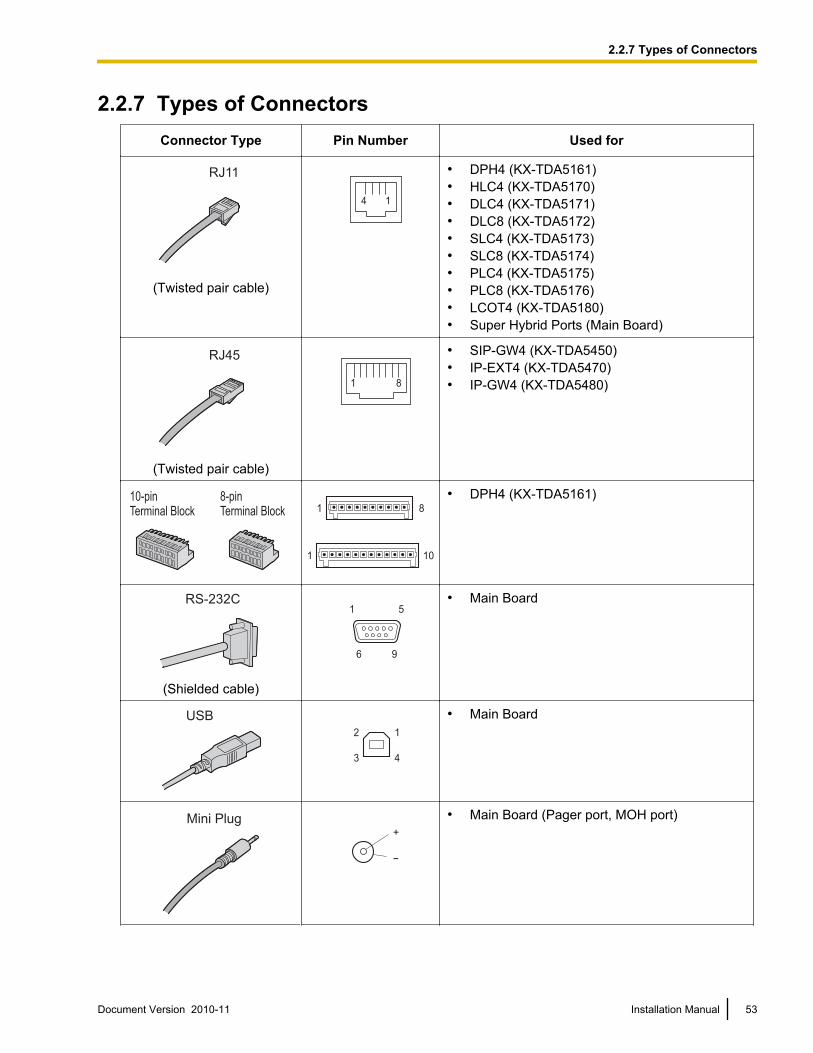
2.2.7 Types of ConnectorsConnector Type Pin Number Used for
RJ11
(Twisted pair cable)
4 1
• DPH4 (KX-TDA5161)• HLC4 (KX-TDA5170)• DLC4 (KX-TDA5171)• DLC8 (KX-TDA5172)• SLC4 (KX-TDA5173)• SLC8 (KX-TDA5174)• PLC4 (KX-TDA5175)• PLC8 (KX-TDA5176)• LCOT4 (KX-TDA5180)• Super Hybrid Ports (Main Board)
RJ45
(Twisted pair cable)
1 8
• SIP-GW4 (KX-TDA5450)• IP-EXT4 (KX-TDA5470)• IP-GW4 (KX-TDA5480)
10-pinTerminal Block
8-pinTerminal Block 81
101
• DPH4 (KX-TDA5161)
RS-232C
(Shielded cable)
6 9
1 5
• Main Board
USB
2
3
1
4
• Main Board
Mini Plug+
-
• Main Board (Pager port, MOH port)
Document Version 2010-11 Installation Manual 53
2.2.7 Types of Connectors
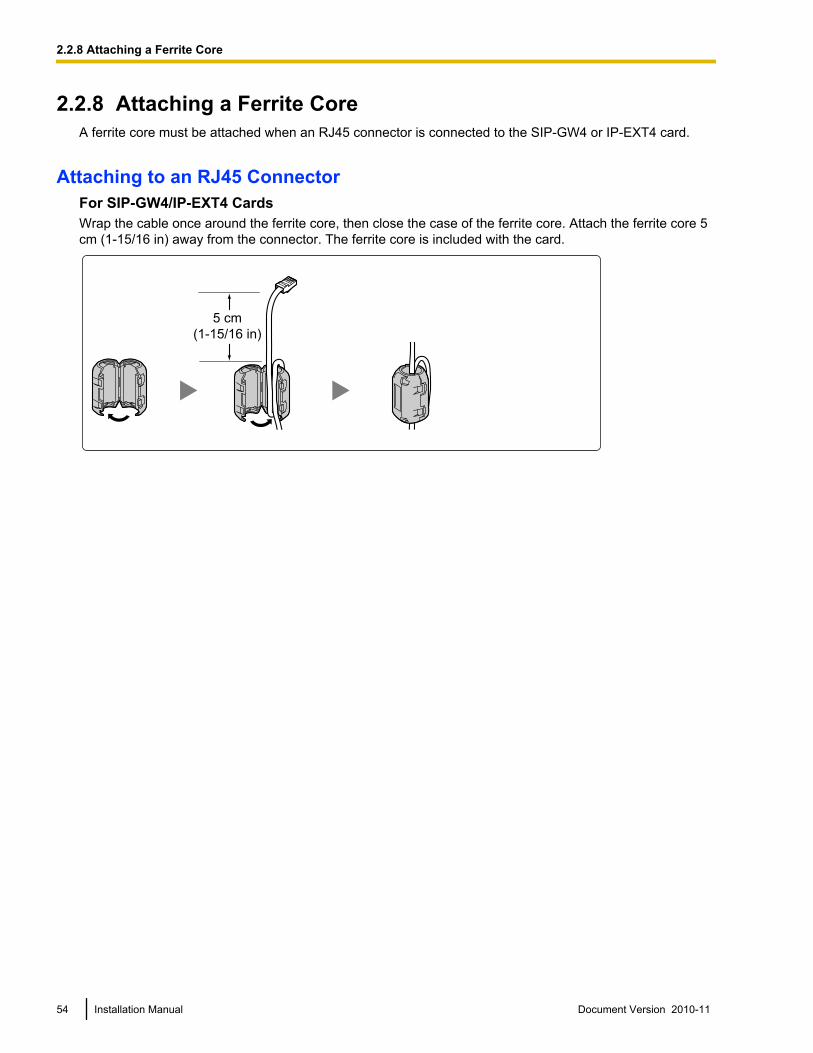
2.2.8 Attaching a Ferrite CoreA ferrite core must be attached when an RJ45 connector is connected to the SIP-GW4 or IP-EXT4 card.
Attaching to an RJ45 ConnectorFor SIP-GW4/IP-EXT4 CardsWrap the cable once around the ferrite core, then close the case of the ferrite core. Attach the ferrite core 5cm (1-15/16 in) away from the connector. The ferrite core is included with the card.
5 cm
(1-15/16 in)
54 Installation Manual Document Version 2010-11
2.2.8 Attaching a Ferrite Core
2.2.9 Wall Mounting (KX-TDA50)Mounting on Wooden Wall
WARNING• Make sure that the wall that the cabinet will be attached to is strong enough to support the
cabinet. If not, it is necessary for the wall to be reinforced.• Only use the wall-mounting equipment (screws, washers) included with the PBX.• Be careful not to drop any components. Dropping components may damage them or cause an
injury.
CAUTION• Do not block the openings of the cabinet. Allow space of at least 20 cm (8 in) above and 10 cm (4 in)
at the sides of the cabinet.• Make sure that the surface behind the cabinet is flat and free of obstacles, so that the openings on the
back of the cabinet will not be blocked.• When driving the screws into the wall, be careful to avoid touching any metal laths, wire laths or metal
plates in the wall.• When this product is no longer in use, make sure to detach it from the wall.
Note• For details about the dimensions and weight of the PBX, refer to "1.3.1 General Description".
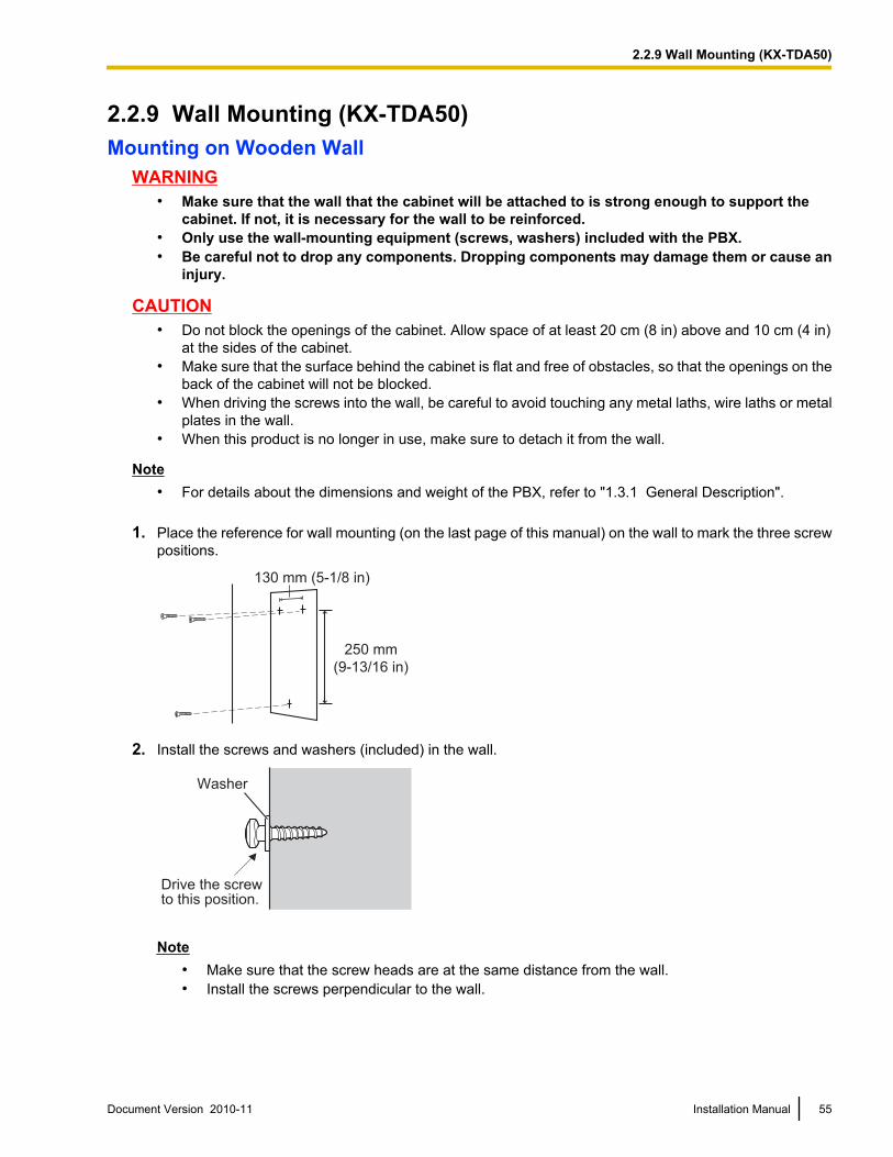
1. Place the reference for wall mounting (on the last page of this manual) on the wall to mark the three screwpositions.
250 mm
(9-13/16 in)
130 mm (5-1/8 in)
2. Install the screws and washers (included) in the wall.
Washer
Drive the screwto this position.
Note• Make sure that the screw heads are at the same distance from the wall.• Install the screws perpendicular to the wall.
Document Version 2010-11 Installation Manual 55
2.2.9 Wall Mounting (KX-TDA50)
3. Hook the main unit on the screw heads.
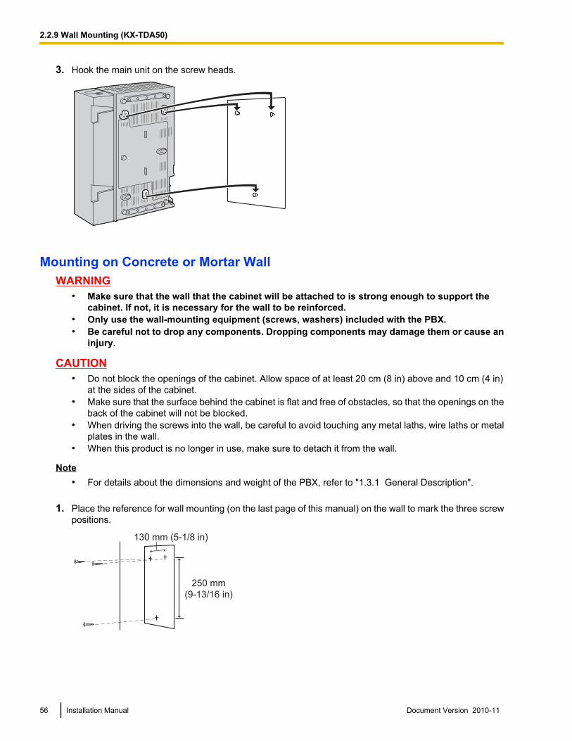
Mounting on Concrete or Mortar WallWARNING
• Make sure that the wall that the cabinet will be attached to is strong enough to support thecabinet. If not, it is necessary for the wall to be reinforced.
• Only use the wall-mounting equipment (screws, washers) included with the PBX.• Be careful not to drop any components. Dropping components may damage them or cause an
injury.
CAUTION• Do not block the openings of the cabinet. Allow space of at least 20 cm (8 in) above and 10 cm (4 in)
at the sides of the cabinet.• Make sure that the surface behind the cabinet is flat and free of obstacles, so that the openings on the
back of the cabinet will not be blocked.• When driving the screws into the wall, be careful to avoid touching any metal laths, wire laths or metal
plates in the wall.• When this product is no longer in use, make sure to detach it from the wall.
Note• For details about the dimensions and weight of the PBX, refer to "1.3.1 General Description".
1. Place the reference for wall mounting (on the last page of this manual) on the wall to mark the three screwpositions.
250 mm
(9-13/16 in)
130 mm (5-1/8 in)
56 Installation Manual Document Version 2010-11
2.2.9 Wall Mounting (KX-TDA50)
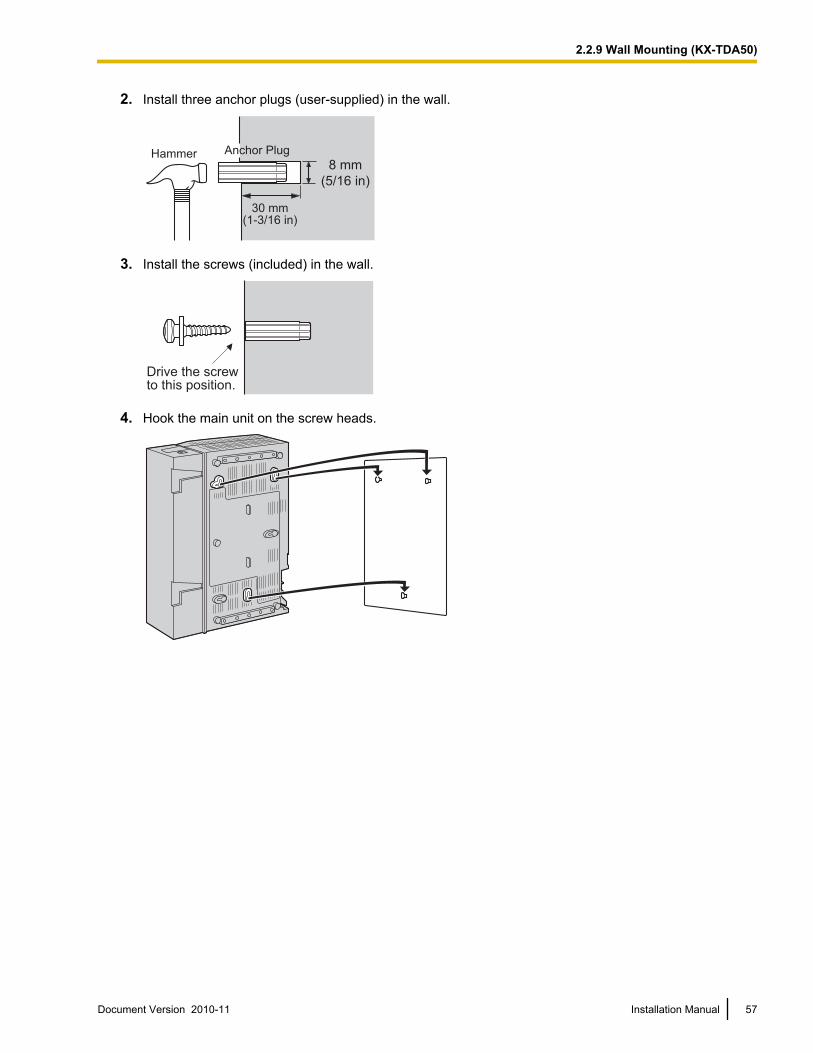
2. Install three anchor plugs (user-supplied) in the wall.
Hammer Anchor Plug
8 mm
(5/16 in)
30 mm(1-3/16 in)
3. Install the screws (included) in the wall.
Drive the screwto this position.
4. Hook the main unit on the screw heads.
Document Version 2010-11 Installation Manual 57
2.2.9 Wall Mounting (KX-TDA50)
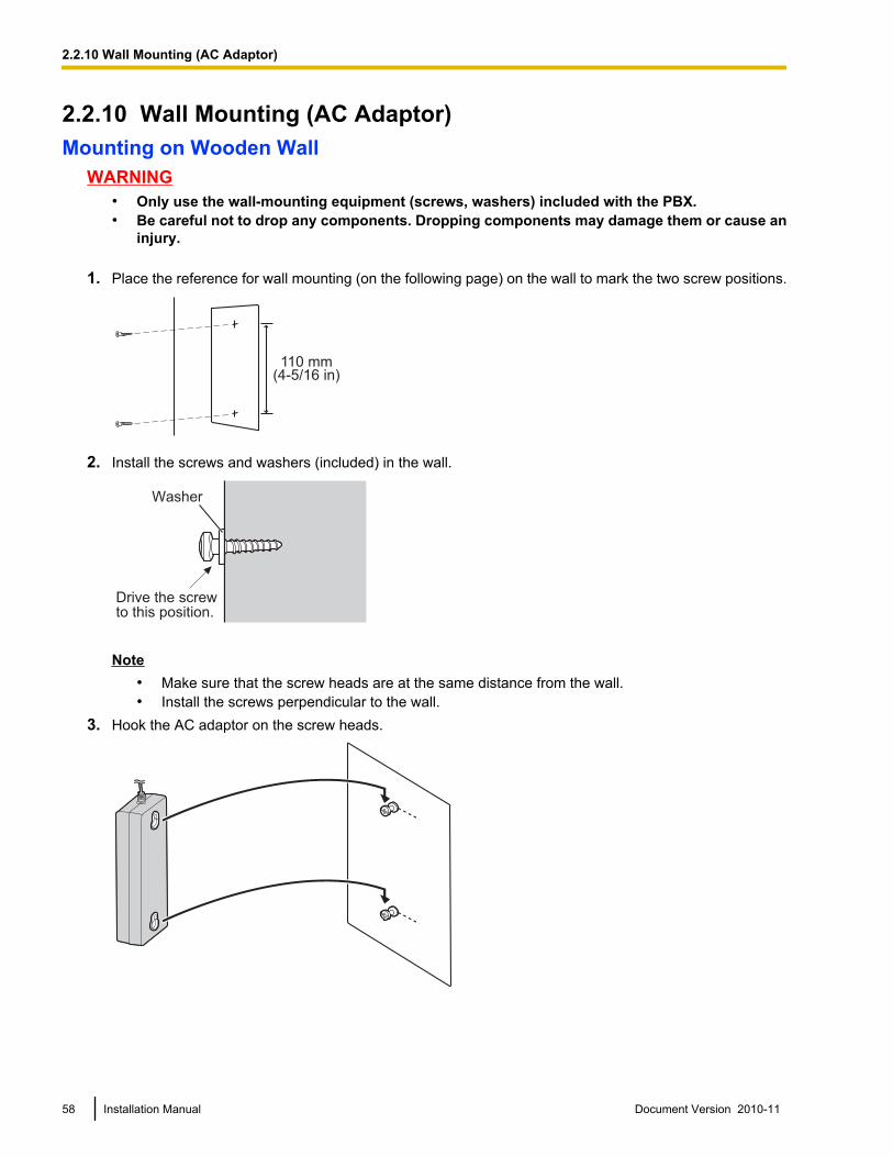
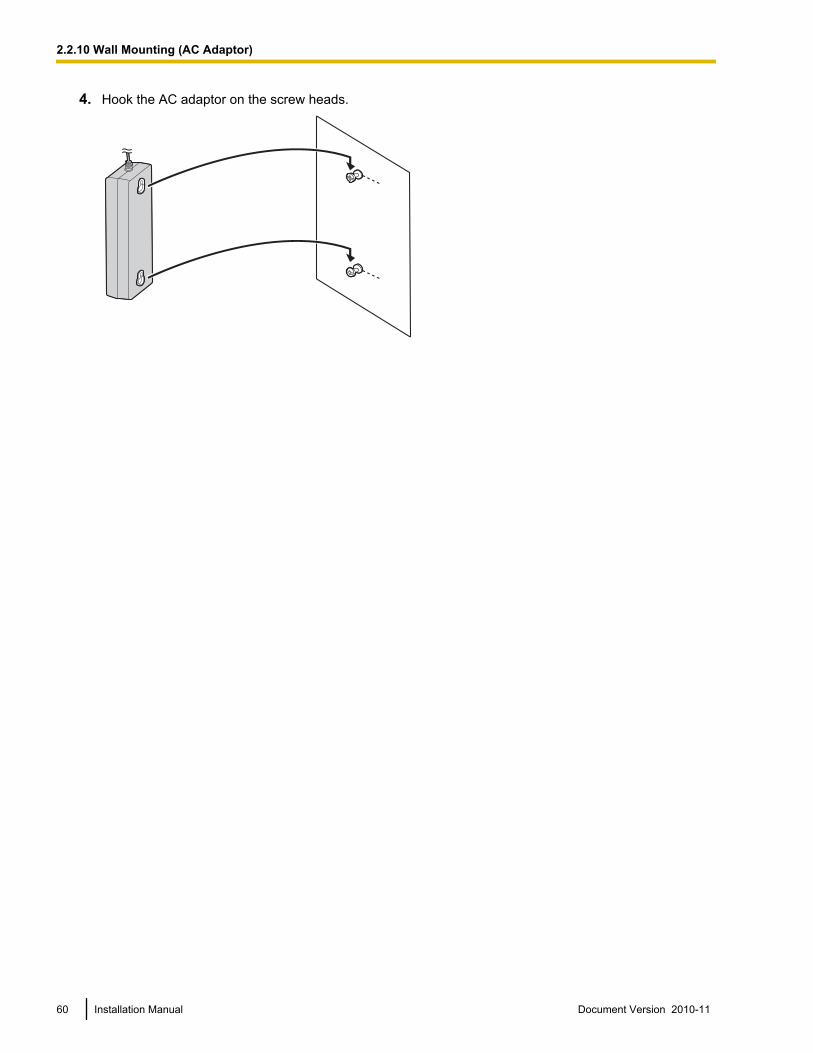
2.2.10 Wall Mounting (AC Adaptor)Mounting on Wooden Wall
WARNING• Only use the wall-mounting equipment (screws, washers) included with the PBX.• Be careful not to drop any components. Dropping components may damage them or cause an
injury.
1. Place the reference for wall mounting (on the following page) on the wall to mark the two screw positions.
110 mm(4-5/16 in)
2. Install the screws and washers (included) in the wall.
Washer
Drive the screwto this position.
Note• Make sure that the screw heads are at the same distance from the wall.• Install the screws perpendicular to the wall.
3. Hook the AC adaptor on the screw heads.
58 Installation Manual Document Version 2010-11
2.2.10 Wall Mounting (AC Adaptor)
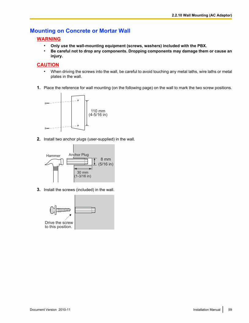
Mounting on Concrete or Mortar WallWARNING
• Only use the wall-mounting equipment (screws, washers) included with the PBX.• Be careful not to drop any components. Dropping components may damage them or cause an
injury.
CAUTION• When driving the screws into the wall, be careful to avoid touching any metal laths, wire laths or metal
plates in the wall.
1. Place the reference for wall mounting (on the following page) on the wall to mark the two screw positions.
110 mm(4-5/16 in)
2. Install two anchor plugs (user-supplied) in the wall.
Hammer Anchor Plug
8 mm
(5/16 in)
30 mm(1-3/16 in)
3. Install the screws (included) in the wall.
Drive the screwto this position.
Document Version 2010-11 Installation Manual 59
2.2.10 Wall Mounting (AC Adaptor)
4. Hook the AC adaptor on the screw heads.
60 Installation Manual Document Version 2010-11
2.2.10 Wall Mounting (AC Adaptor)
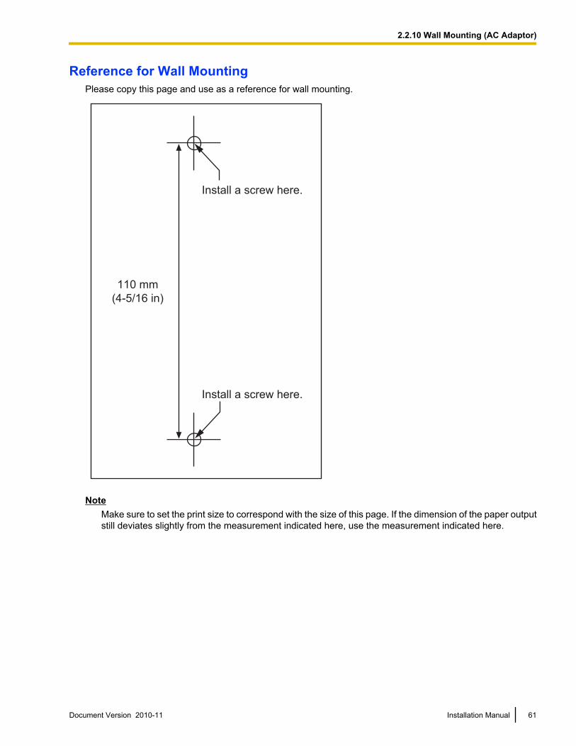
Reference for Wall MountingPlease copy this page and use as a reference for wall mounting.
Install a screw here.
Install a screw here.
110 mm
(4-5/16 in)
NoteMake sure to set the print size to correspond with the size of this page. If the dimension of the paper outputstill deviates slightly from the measurement indicated here, use the measurement indicated here.
Document Version 2010-11 Installation Manual 61
2.2.10 Wall Mounting (AC Adaptor)
2.2.11 Surge Protector InstallationCAUTION
Performing surge protection is essential. Make sure to follow the instructions in this section.
OverviewA massive electrical surge can be caused if lightning strikes a telephone cable 10 m (33 ft) above ground, orif a telephone line comes into contact with a power line. A surge protector is a device that is connected to aCO line to prevent potentially dangerous electrical surges from entering the building via the CO line anddamaging the PBX and connected equipment.
To protect the system from electrical surges, we strongly recommend connecting the system to a surgeprotector that meets the following specifications:• Surge arrestor type: 3-electrode arrestor• DC spark-over voltage: 230 V• Maximum peak current: at least 10 kAAdditionally, proper grounding is very important for the protection of the system (refer to "2.2.5 Frame GroundConnection").
Many countries/areas have regulations requiring surge protection. Be sure to comply with all applicable laws,regulations, and guidelines.
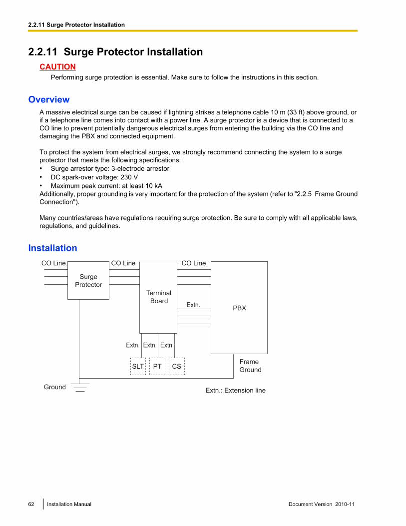
Installation
CS
Extn.
Extn. Extn. Extn.
SLT PT
CO Line CO Line CO Line
Extn.: Extension line
Surge
Protector
Terminal
BoardPBX
Frame
Ground
Ground
62 Installation Manual Document Version 2010-11
2.2.11 Surge Protector Installation
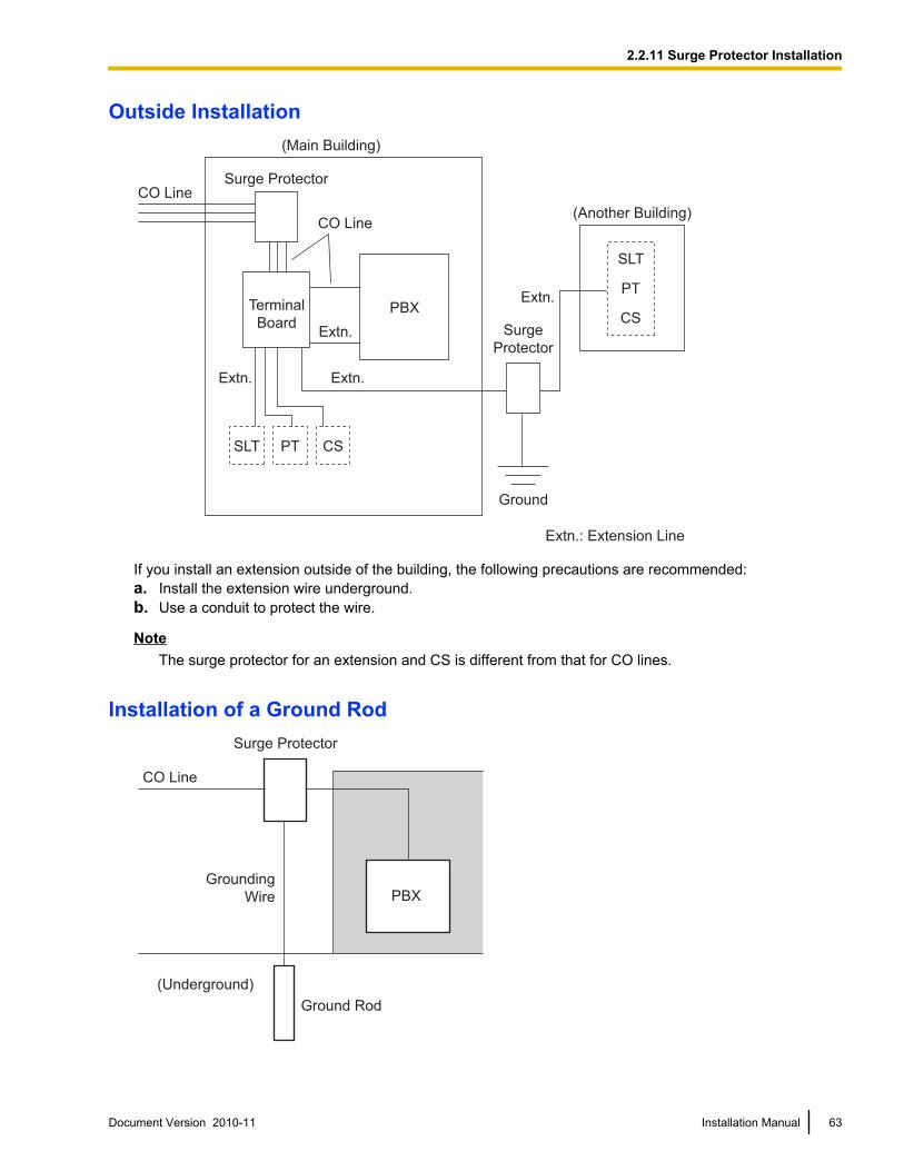
Outside Installation
CSSLT PT
(Main Building)
CO Line
CO Line
Extn.
Extn.
Extn.: Extension Line
Ground
(Another Building)
Extn. Extn.
Surge Protector
Terminal
BoardSurge
Protector
SLT
PT
PBXCS
If you install an extension outside of the building, the following precautions are recommended:a. Install the extension wire underground.b. Use a conduit to protect the wire.
NoteThe surge protector for an extension and CS is different from that for CO lines.
Installation of a Ground Rod
CO Line
PBX Grounding
Wire
Ground Rod
(Underground)
Surge Protector
Document Version 2010-11 Installation Manual 63
2.2.11 Surge Protector Installation

1. Connect the ground rod to the surge protector using a grounding wire with a cross-sectional area of at least1.3 mm2.
2. Bury the ground rod near the protector. The grounding wire should be as short as possible.3. The grounding wire should run straight to the ground rod. Do not run the wire around other objects.4. Bury the ground rod at least 50 cm (20 in) underground.
Note• The above figures are recommendations only.• The length of ground rod and the required depth depend on the composition of the soil.
64 Installation Manual Document Version 2010-11
2.2.11 Surge Protector Installation
2.3 Information about the CO Line Cards
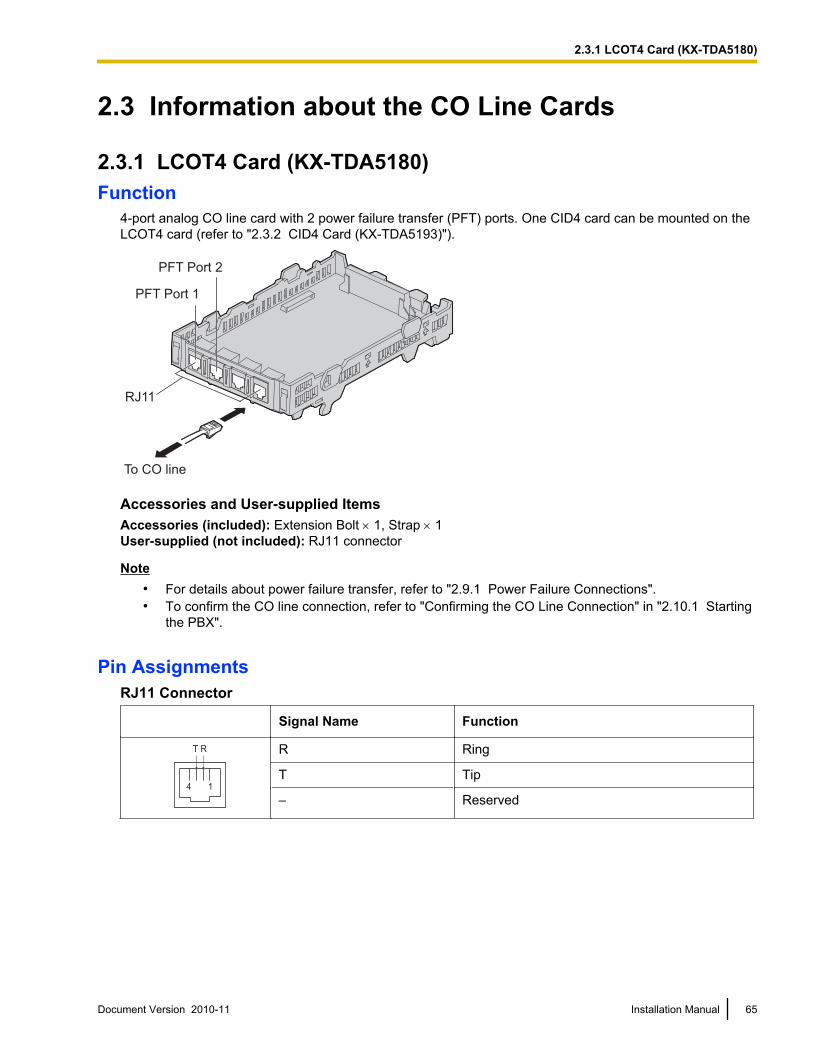
2.3.1 LCOT4 Card (KX-TDA5180)Function
4-port analog CO line card with 2 power failure transfer (PFT) ports. One CID4 card can be mounted on theLCOT4 card (refer to "2.3.2 CID4 Card (KX-TDA5193)").
To CO line
RJ11
PFT Port 1
PFT Port 2
Accessories and User-supplied ItemsAccessories (included): Extension Bolt ´ 1, Strap ´ 1User-supplied (not included): RJ11 connector
Note• For details about power failure transfer, refer to "2.9.1 Power Failure Connections".• To confirm the CO line connection, refer to "Confirming the CO Line Connection" in "2.10.1 Starting
the PBX".
Pin AssignmentsRJ11 Connector
Signal Name Function
4 1
T R R Ring
T Tip
– Reserved
Document Version 2010-11 Installation Manual 65
2.3.1 LCOT4 Card (KX-TDA5180)
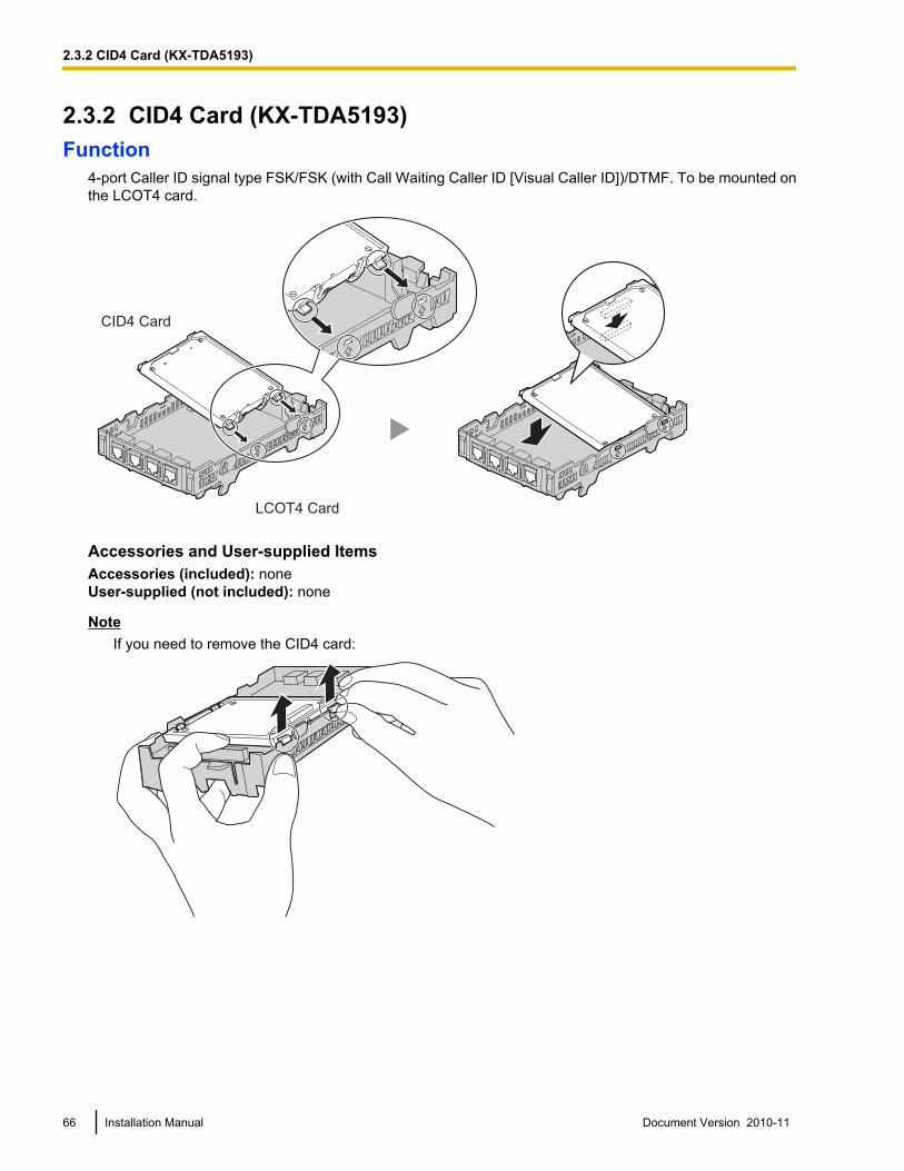
2.3.2 CID4 Card (KX-TDA5193)Function
4-port Caller ID signal type FSK/FSK (with Call Waiting Caller ID [Visual Caller ID])/DTMF. To be mounted onthe LCOT4 card.
CID4 Card
LCOT4 Card
Accessories and User-supplied ItemsAccessories (included): noneUser-supplied (not included): none
NoteIf you need to remove the CID4 card:
66 Installation Manual Document Version 2010-11
2.3.2 CID4 Card (KX-TDA5193)
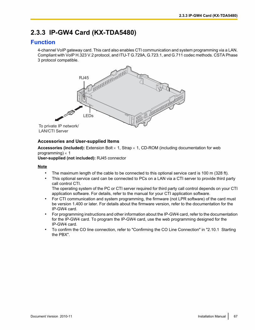
2.3.3 IP-GW4 Card (KX-TDA5480)Function
4-channel VoIP gateway card. This card also enables CTI communication and system programming via a LAN.Compliant with VoIP H.323 V.2 protocol, and ITU-T G.729A, G.723.1, and G.711 codec methods. CSTA Phase3 protocol compatible.
To private IP network/
LAN/CTI Server
RJ45
LEDs
Accessories and User-supplied ItemsAccessories (included): Extension Bolt ´ 1, Strap ´ 1, CD-ROM (including documentation for webprogramming) ´ 1User-supplied (not included): RJ45 connector
Note• The maximum length of the cable to be connected to this optional service card is 100 m (328 ft).• This optional service card can be connected to PCs on a LAN via a CTI server to provide third party
call control CTI.The operating system of the PC or CTI server required for third party call control depends on your CTIapplication software. For details, refer to the manual for your CTI application software.
• For CTI communication and system programming, the firmware (not LPR software) of the card mustbe version 1.400 or later. For details about the firmware version, refer to the documentation for theIP-GW4 card.
• For programming instructions and other information about the IP-GW4 card, refer to the documentationfor the IP-GW4 card. To program the IP-GW4 card, use the web programming designed for theIP-GW4 card.
• To confirm the CO line connection, refer to "Confirming the CO Line Connection" in "2.10.1 Startingthe PBX".
Document Version 2010-11 Installation Manual 67
2.3.3 IP-GW4 Card (KX-TDA5480)
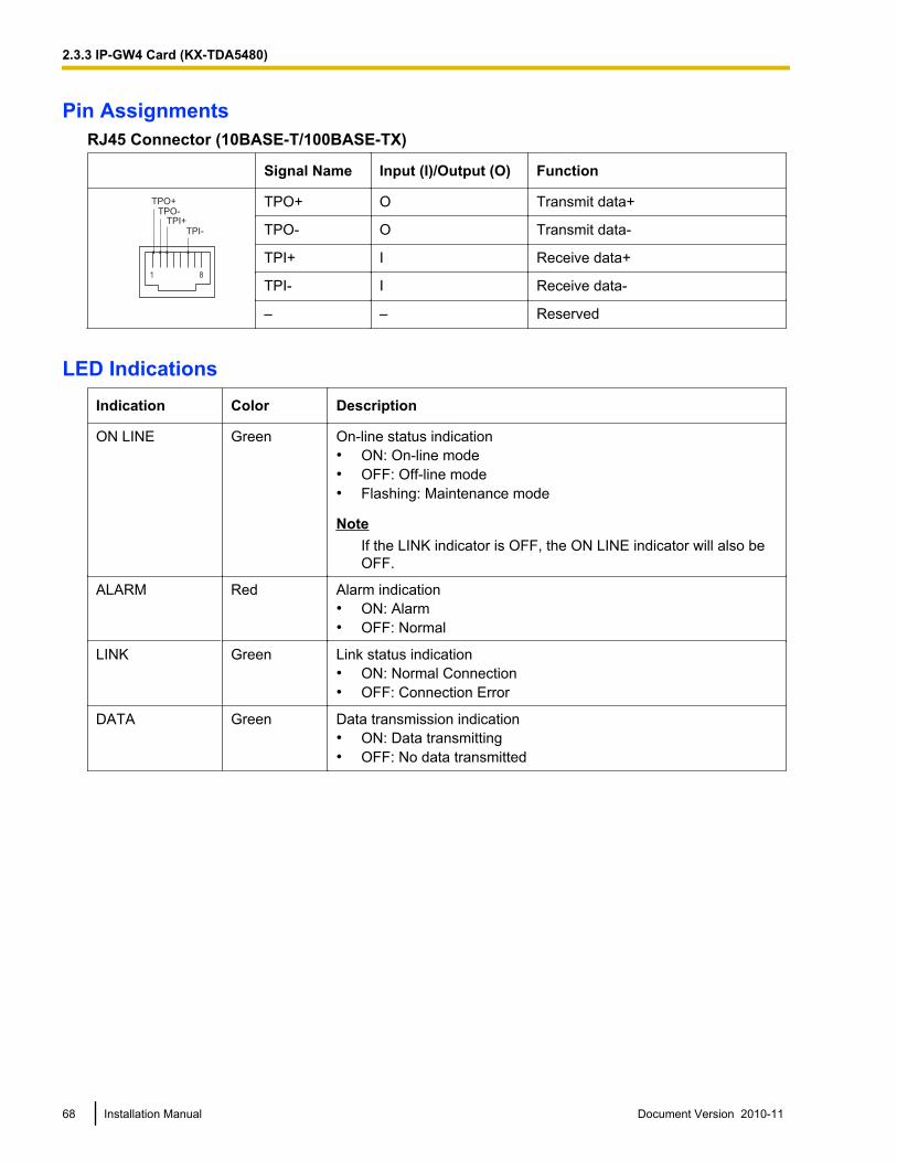
Pin AssignmentsRJ45 Connector (10BASE-T/100BASE-TX)
Signal Name Input (I)/Output (O) Function
1 8
TPO+
TPO-
TPI+
TPI-
TPO+ O Transmit data+
TPO- O Transmit data-
TPI+ I Receive data+
TPI- I Receive data-
– – Reserved
LED IndicationsIndication Color Description
ON LINE Green On-line status indication• ON: On-line mode• OFF: Off-line mode• Flashing: Maintenance mode
NoteIf the LINK indicator is OFF, the ON LINE indicator will also beOFF.
ALARM Red Alarm indication• ON: Alarm• OFF: Normal
LINK Green Link status indication• ON: Normal Connection• OFF: Connection Error
DATA Green Data transmission indication• ON: Data transmitting• OFF: No data transmitted
68 Installation Manual Document Version 2010-11
2.3.3 IP-GW4 Card (KX-TDA5480)
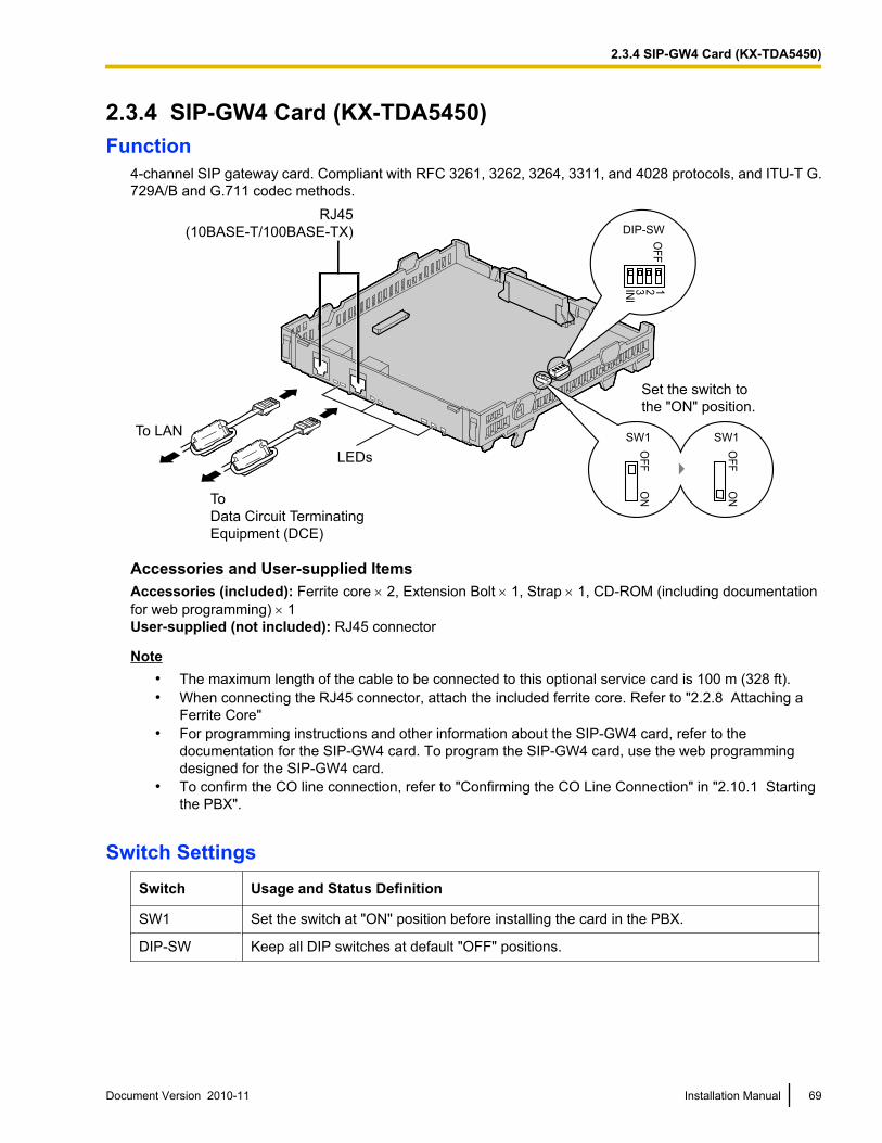
2.3.4 SIP-GW4 Card (KX-TDA5450)Function
4-channel SIP gateway card. Compliant with RFC 3261, 3262, 3264, 3311, and 4028 protocols, and ITU-T G.729A/B and G.711 codec methods.
To LAN
RJ45
(10BASE-T/100BASE-TX)
LEDs
Set the switch to
the "ON" position.
OF
FO
N
SW1
OF
FO
N
SW1
OF
F123IN
I
DIP-SW
To
Data Circuit Terminating
Equipment (DCE)
Accessories and User-supplied ItemsAccessories (included): Ferrite core ´ 2, Extension Bolt ´ 1, Strap ´ 1, CD-ROM (including documentationfor web programming) ´ 1User-supplied (not included): RJ45 connector
Note• The maximum length of the cable to be connected to this optional service card is 100 m (328 ft).• When connecting the RJ45 connector, attach the included ferrite core. Refer to "2.2.8 Attaching a
Ferrite Core"• For programming instructions and other information about the SIP-GW4 card, refer to the
documentation for the SIP-GW4 card. To program the SIP-GW4 card, use the web programmingdesigned for the SIP-GW4 card.
• To confirm the CO line connection, refer to "Confirming the CO Line Connection" in "2.10.1 Startingthe PBX".
Switch SettingsSwitch Usage and Status Definition
SW1 Set the switch at "ON" position before installing the card in the PBX.
DIP-SW Keep all DIP switches at default "OFF" positions.
Document Version 2010-11 Installation Manual 69
2.3.4 SIP-GW4 Card (KX-TDA5450)
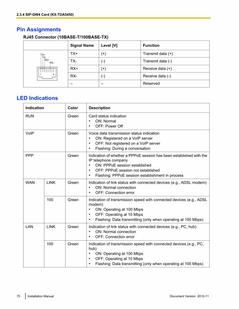
Pin AssignmentsRJ45 Connector (10BASE-T/100BASE-TX)
Signal Name Level [V] Function
1 8
TX+
TX-
RX+
RX-
TX+ (+) Transmit data (+)
TX- (-) Transmit data (-)
RX+ (+) Receive data (+)
RX- (-) Receive data (-)
– – Reserved
LED IndicationsIndication Color Description
RUN Green Card status indication• ON: Normal• OFF: Power Off
VoIP Green Voice data transmission status indication• ON: Registered on a VoIP server• OFF: Not registered on a VoIP server• Flashing: During a conversation
PPP Green Indication of whether a PPPoE session has been established with theIP telephone company• ON: PPPoE session established• OFF: PPPoE session not established• Flashing: PPPoE session establishment in process
WAN LINK Green Indication of link status with connected devices (e.g., ADSL modem)• ON: Normal connection• OFF: Connection error
100 Green Indication of transmission speed with connected devices (e.g., ADSLmodem)• ON: Operating at 100 Mbps• OFF: Operating at 10 Mbps• Flashing: Data transmitting (only when operating at 100 Mbps)
LAN LINK Green Indication of link status with connected devices (e.g., PC, hub)• ON: Normal connection• OFF: Connection error
100 Green Indication of transmission speed with connected devices (e.g., PC,hub)• ON: Operating at 100 Mbps• OFF: Operating at 10 Mbps• Flashing: Data transmitting (only when operating at 100 Mbps)
70 Installation Manual Document Version 2010-11
2.3.4 SIP-GW4 Card (KX-TDA5450)
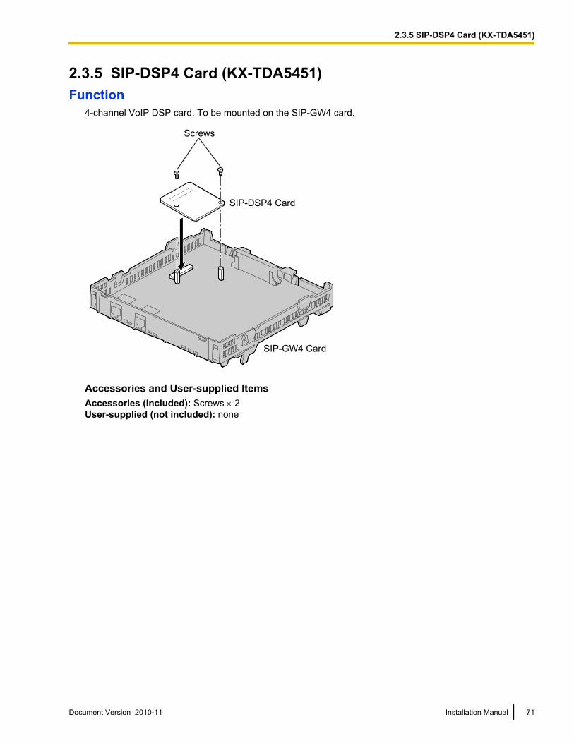
2.3.5 SIP-DSP4 Card (KX-TDA5451)Function
4-channel VoIP DSP card. To be mounted on the SIP-GW4 card.
SIP-DSP4 Card
SIP-GW4 Card
Screws
Accessories and User-supplied ItemsAccessories (included): Screws ´ 2User-supplied (not included): none
Document Version 2010-11 Installation Manual 71
2.3.5 SIP-DSP4 Card (KX-TDA5451)
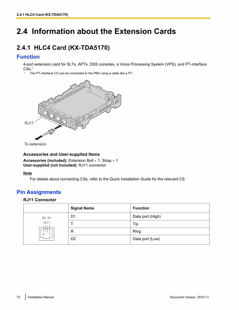
2.4 Information about the Extension Cards
2.4.1 HLC4 Card (KX-TDA5170)Function
4-port extension card for SLTs, APTs, DSS consoles, a Voice Processing System (VPS), and PT-interfaceCSs.*1
*1 The PT-interface CS can be connected to the PBX using a cable like a PT.
To extension
RJ11
Accessories and User-supplied ItemsAccessories (included): Extension Bolt ´ 1, Strap ´ 1User-supplied (not included): RJ11 connector
NoteFor details about connecting CSs, refer to the Quick Installation Guide for the relevant CS.
Pin AssignmentsRJ11 Connector
Signal Name Function
4 1
R T
D2 D1D1 Data port (High)
T Tip
R Ring
D2 Data port (Low)
72 Installation Manual Document Version 2010-11
2.4.1 HLC4 Card (KX-TDA5170)
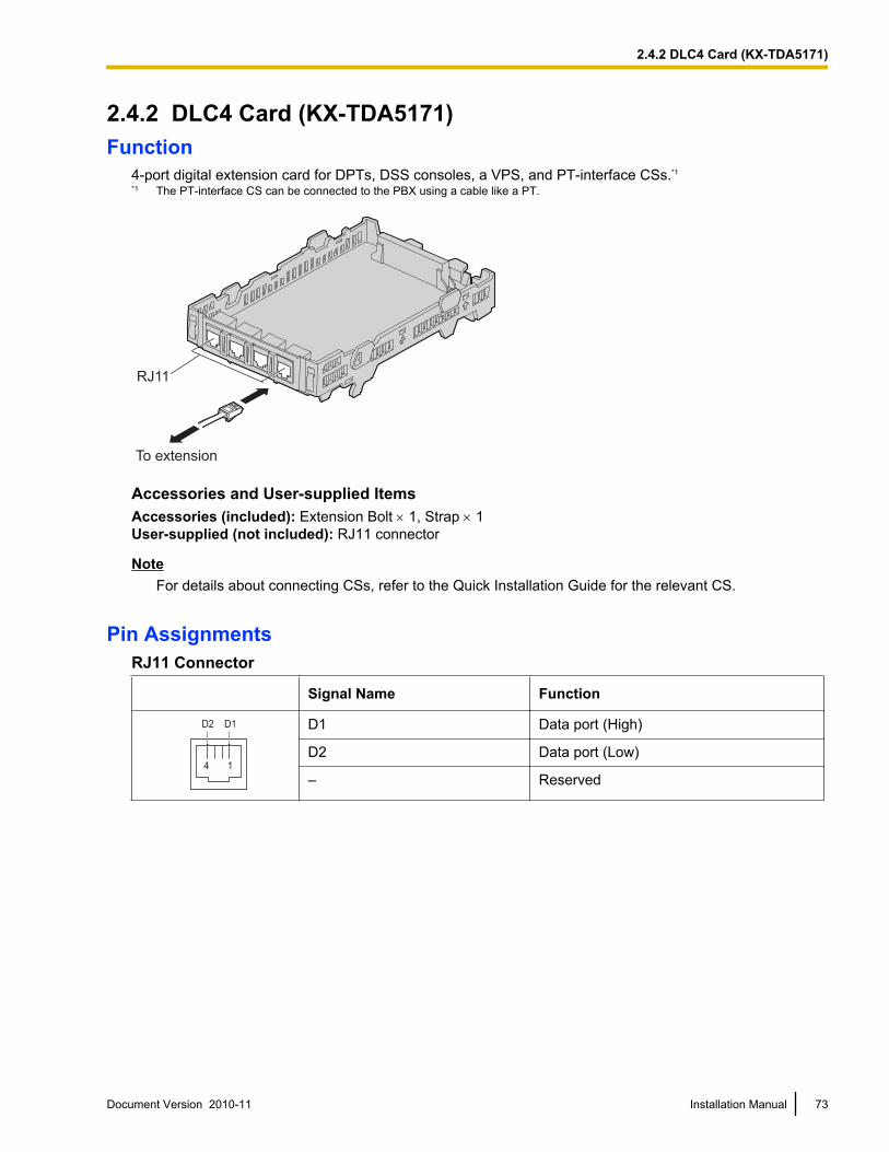
2.4.2 DLC4 Card (KX-TDA5171)Function
4-port digital extension card for DPTs, DSS consoles, a VPS, and PT-interface CSs.*1
*1 The PT-interface CS can be connected to the PBX using a cable like a PT.
To extension
RJ11
Accessories and User-supplied ItemsAccessories (included): Extension Bolt ´ 1, Strap ´ 1User-supplied (not included): RJ11 connector
NoteFor details about connecting CSs, refer to the Quick Installation Guide for the relevant CS.
Pin AssignmentsRJ11 Connector
Signal Name Function
4 1
D2 D1 D1 Data port (High)
D2 Data port (Low)
– Reserved
Document Version 2010-11 Installation Manual 73
2.4.2 DLC4 Card (KX-TDA5171)
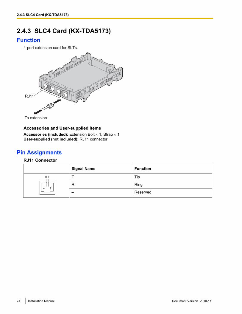
2.4.3 SLC4 Card (KX-TDA5173)Function
4-port extension card for SLTs.
To extension
RJ11
Accessories and User-supplied ItemsAccessories (included): Extension Bolt ´ 1, Strap ´ 1User-supplied (not included): RJ11 connector
Pin AssignmentsRJ11 Connector
Signal Name Function
4 1
R T T Tip
R Ring
– Reserved
74 Installation Manual Document Version 2010-11
2.4.3 SLC4 Card (KX-TDA5173)
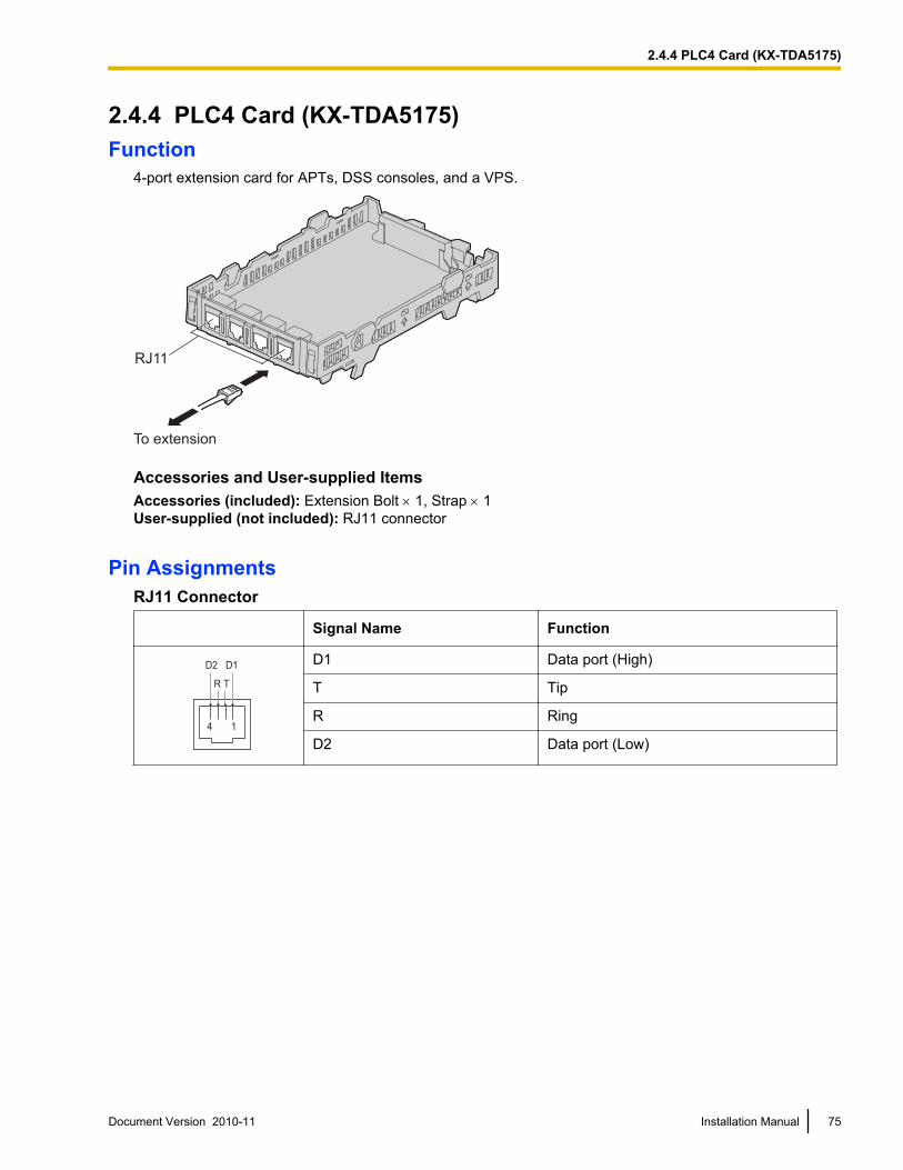
2.4.4 PLC4 Card (KX-TDA5175)Function
4-port extension card for APTs, DSS consoles, and a VPS.
To extension
RJ11
Accessories and User-supplied ItemsAccessories (included): Extension Bolt ´ 1, Strap ´ 1User-supplied (not included): RJ11 connector
Pin AssignmentsRJ11 Connector
Signal Name Function
4 1
R T
D2 D1D1 Data port (High)
T Tip
R Ring
D2 Data port (Low)
Document Version 2010-11 Installation Manual 75
2.4.4 PLC4 Card (KX-TDA5175)
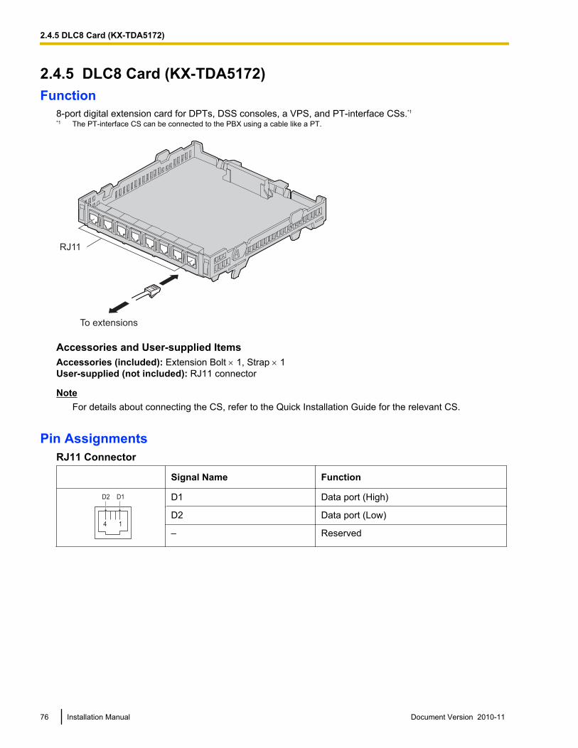
2.4.5 DLC8 Card (KX-TDA5172)Function
8-port digital extension card for DPTs, DSS consoles, a VPS, and PT-interface CSs.*1
*1 The PT-interface CS can be connected to the PBX using a cable like a PT.
To extensions
RJ11
Accessories and User-supplied ItemsAccessories (included): Extension Bolt ´ 1, Strap ´ 1User-supplied (not included): RJ11 connector
NoteFor details about connecting the CS, refer to the Quick Installation Guide for the relevant CS.
Pin AssignmentsRJ11 Connector
Signal Name Function
4 1
D2 D1 D1 Data port (High)
D2 Data port (Low)
– Reserved
76 Installation Manual Document Version 2010-11
2.4.5 DLC8 Card (KX-TDA5172)
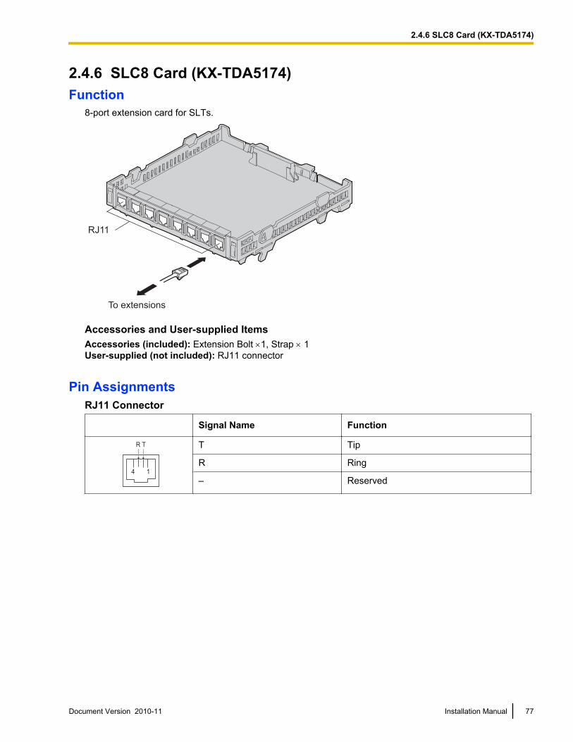
2.4.6 SLC8 Card (KX-TDA5174)Function
8-port extension card for SLTs.
To extensions
RJ11
Accessories and User-supplied ItemsAccessories (included): Extension Bolt ´1, Strap ´ 1User-supplied (not included): RJ11 connector
Pin AssignmentsRJ11 Connector
Signal Name Function
4 1
R T T Tip
R Ring
– Reserved
Document Version 2010-11 Installation Manual 77
2.4.6 SLC8 Card (KX-TDA5174)
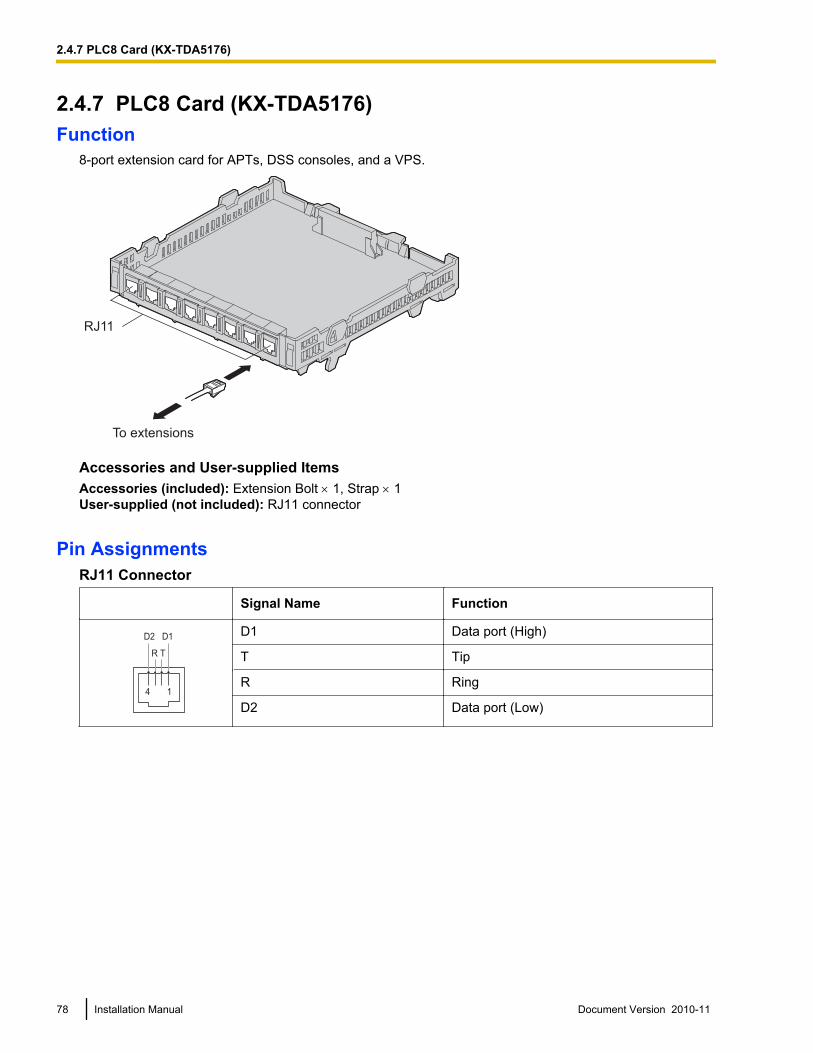
2.4.7 PLC8 Card (KX-TDA5176)Function
8-port extension card for APTs, DSS consoles, and a VPS.
To extensions
RJ11
Accessories and User-supplied ItemsAccessories (included): Extension Bolt ´ 1, Strap ´ 1User-supplied (not included): RJ11 connector
Pin AssignmentsRJ11 Connector
Signal Name Function
4 1
R T
D2 D1D1 Data port (High)
T Tip
R Ring
D2 Data port (Low)
78 Installation Manual Document Version 2010-11
2.4.7 PLC8 Card (KX-TDA5176)
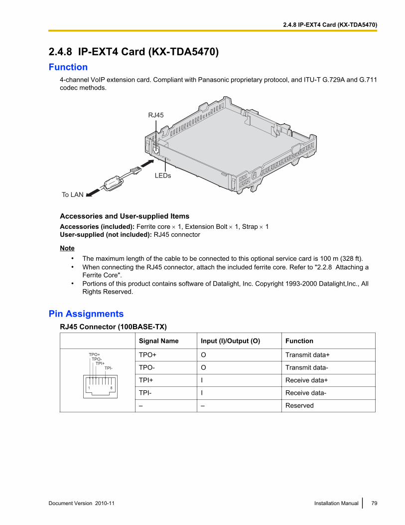
2.4.8 IP-EXT4 Card (KX-TDA5470)Function
4-channel VoIP extension card. Compliant with Panasonic proprietary protocol, and ITU-T G.729A and G.711codec methods.
RJ45
LEDs
To LAN
Accessories and User-supplied ItemsAccessories (included): Ferrite core ´ 1, Extension Bolt ´ 1, Strap ´ 1User-supplied (not included): RJ45 connector
Note• The maximum length of the cable to be connected to this optional service card is 100 m (328 ft).• When connecting the RJ45 connector, attach the included ferrite core. Refer to "2.2.8 Attaching a
Ferrite Core".• Portions of this product contains software of Datalight, Inc. Copyright 1993-2000 Datalight,Inc., All
Rights Reserved.
Pin AssignmentsRJ45 Connector (100BASE-TX)
Signal Name Input (I)/Output (O) Function
1 8
TPO+
TPO-
TPI+
TPI-
TPO+ O Transmit data+
TPO- O Transmit data-
TPI+ I Receive data+
TPI- I Receive data-
– – Reserved
Document Version 2010-11 Installation Manual 79
2.4.8 IP-EXT4 Card (KX-TDA5470)
LED IndicationsIndication Color Description
ON LINE Green On-line status indication• ON: At least one port is in use (an IP-PT is connected)• OFF: No ports are in use (no IP-PTs are connected)
NoteIf the LINK indicator is OFF, the ON LINE indicator will also be OFF.
ALARM Red Alarm indication• ON: Alarm• OFF: Normal
LINK Green Link status indication• ON: Normal connection• OFF: Connection error
DATA Green Data transmission indication• ON: Data transmitting• OFF: No data transmitted
80 Installation Manual Document Version 2010-11
2.4.8 IP-EXT4 Card (KX-TDA5470)
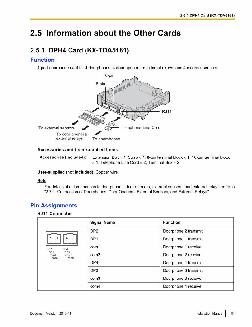
2.5 Information about the Other Cards
2.5.1 DPH4 Card (KX-TDA5161)Function
4-port doorphone card for 4 doorphones, 4 door openers or external relays, and 4 external sensors.
Telephone Line Cord
8-pin
10-pin
RJ11
To doorphonesTo door openers/external relays
To external sensors
Accessories and User-supplied ItemsAccessories (included): Extension Bolt ´ 1, Strap ´ 1, 8-pin terminal block ´ 1, 10-pin terminal block
´ 1, Telephone Line Cord ´ 2, Terminal Box ´ 2
User-supplied (not included): Copper wire
NoteFor details about connection to doorphones, door openers, external sensors, and external relays, refer to"2.7.1 Connection of Doorphones, Door Openers, External Sensors, and External Relays".
Pin AssignmentsRJ11 Connector
Signal Name Function
DP2
DP1
com1
com2
DP4
DP3
com3
com4
5 81 4
DP2 Doorphone 2 transmit
DP1 Doorphone 1 transmit
com1 Doorphone 1 receive
com2 Doorphone 2 receive
DP4 Doorphone 4 transmit
DP3 Doorphone 3 transmit
com3 Doorphone 3 receive
com4 Doorphone 4 receive
Document Version 2010-11 Installation Manual 81
2.5.1 DPH4 Card (KX-TDA5161)
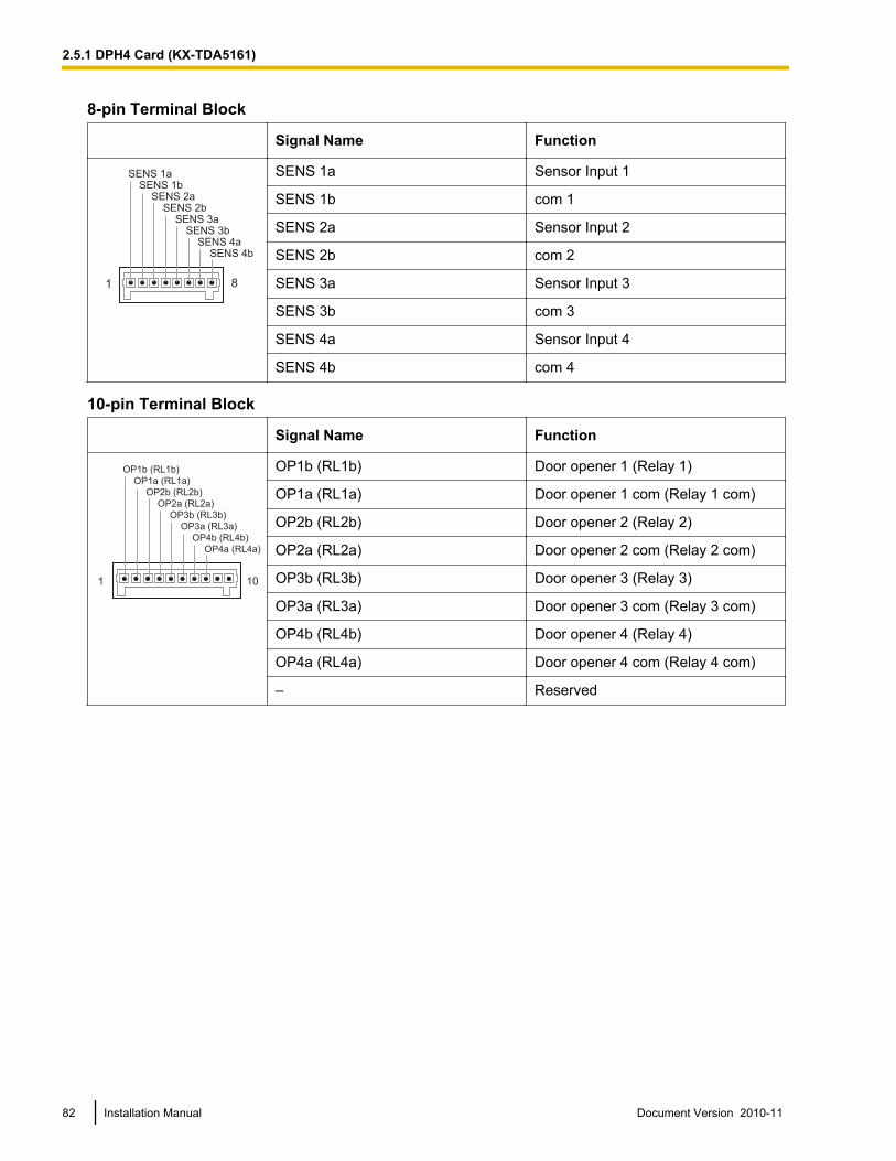
8-pin Terminal Block
Signal Name Function
1 8
SENS 1a
SENS 1b
SENS 2a
SENS 2b
SENS 3a
SENS 3b
SENS 4a
SENS 4b
SENS 1a Sensor Input 1
SENS 1b com 1
SENS 2a Sensor Input 2
SENS 2b com 2
SENS 3a Sensor Input 3
SENS 3b com 3
SENS 4a Sensor Input 4
SENS 4b com 4
10-pin Terminal Block
Signal Name Function
1 10
OP1b (RL1b)
OP1a (RL1a)
OP2b (RL2b)
OP2a (RL2a)
OP3b (RL3b)
OP3a (RL3a)
OP4b (RL4b)
OP4a (RL4a)
OP1b (RL1b) Door opener 1 (Relay 1)
OP1a (RL1a) Door opener 1 com (Relay 1 com)
OP2b (RL2b) Door opener 2 (Relay 2)
OP2a (RL2a) Door opener 2 com (Relay 2 com)
OP3b (RL3b) Door opener 3 (Relay 3)
OP3a (RL3a) Door opener 3 com (Relay 3 com)
OP4b (RL4b) Door opener 4 (Relay 4)
OP4a (RL4a) Door opener 4 com (Relay 4 com)
– Reserved
82 Installation Manual Document Version 2010-11
2.5.1 DPH4 Card (KX-TDA5161)
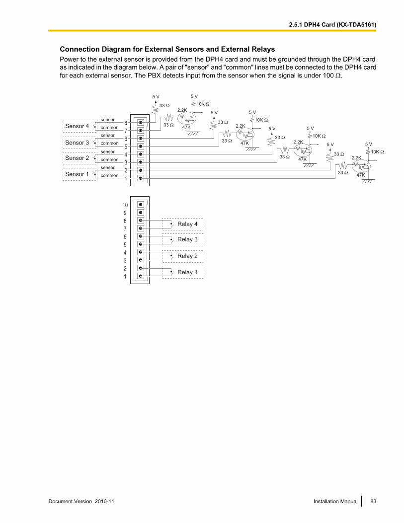
Connection Diagram for External Sensors and External RelaysPower to the external sensor is provided from the DPH4 card and must be grounded through the DPH4 cardas indicated in the diagram below. A pair of "sensor" and "common" lines must be connected to the DPH4 cardfor each external sensor. The PBX detects input from the sensor when the signal is under 100 W.
5 V
Sensor 4
Sensor 3
Sensor 2
Sensor 1
8
7
6
5
4
3
2
1
Relay 4
Relay 3
Relay 2
Relay 1
10
9
8
7
6
5
4
3
2
1
5 V
10K Ω2.2K
47K
33 Ω
33 Ω
5 V 5 V
10K Ω2.2K
47K
33 Ω
33 Ω
5 V 5 V
10K Ω2.2K
47K
33 Ω
33 Ω
5 V 5 V
10K Ω2.2K
47K
33 Ω
33 Ω
sensor
common
sensor
common
sensor
common
sensor
common
Document Version 2010-11 Installation Manual 83
2.5.1 DPH4 Card (KX-TDA5161)
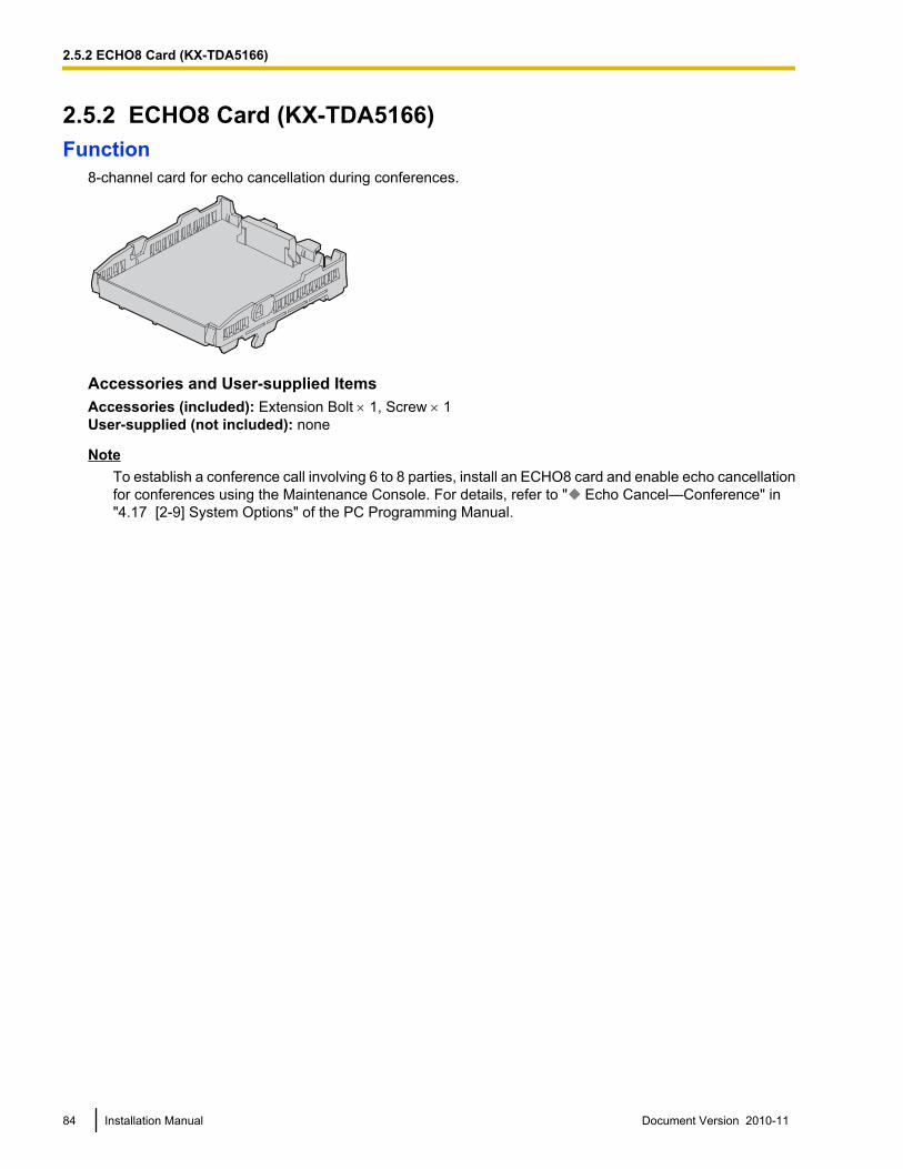
2.5.2 ECHO8 Card (KX-TDA5166)Function
8-channel card for echo cancellation during conferences.
Accessories and User-supplied ItemsAccessories (included): Extension Bolt ´ 1, Screw ´ 1User-supplied (not included): none
NoteTo establish a conference call involving 6 to 8 parties, install an ECHO8 card and enable echo cancellationfor conferences using the Maintenance Console. For details, refer to " Echo Cancel—Conference" in"4.17 [2-9] System Options" of the PC Programming Manual.
84 Installation Manual Document Version 2010-11
2.5.2 ECHO8 Card (KX-TDA5166)
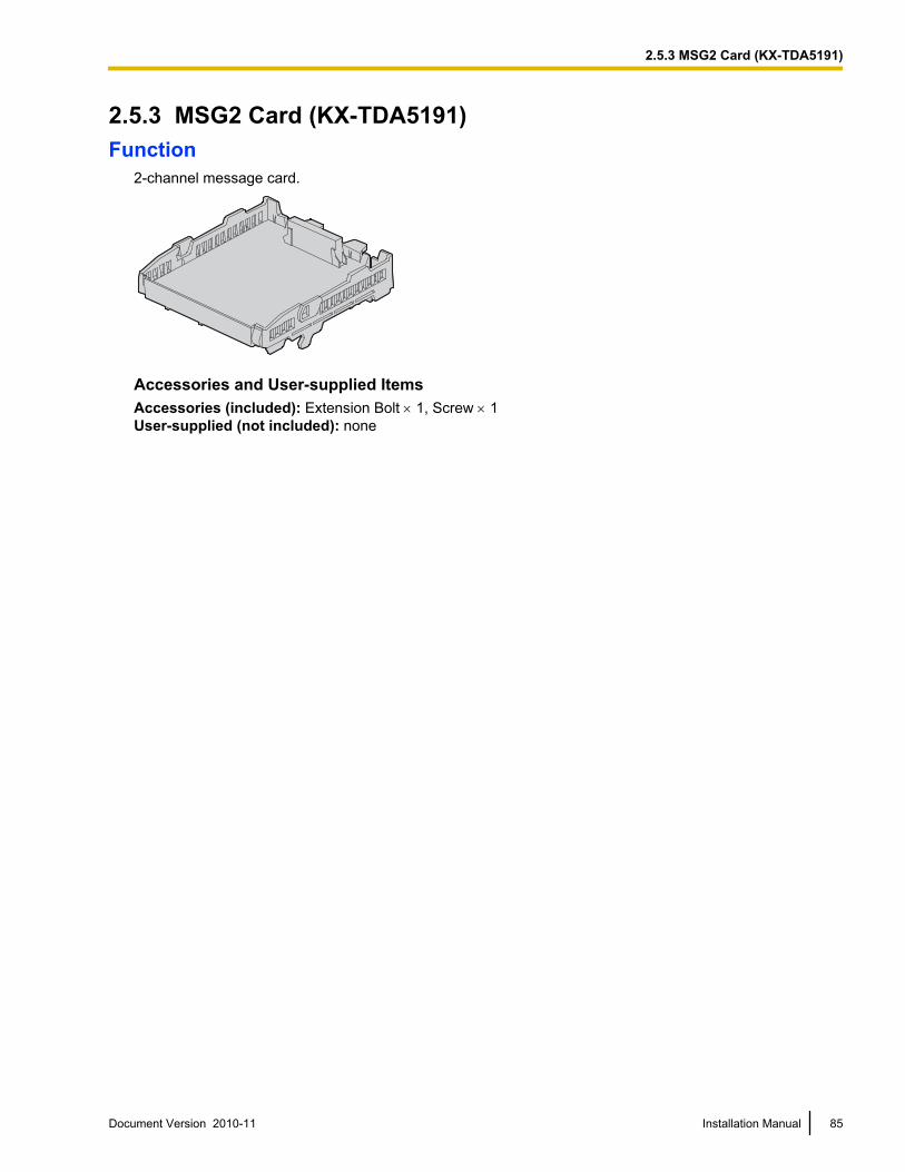
2.5.3 MSG2 Card (KX-TDA5191)Function
2-channel message card.
Accessories and User-supplied ItemsAccessories (included): Extension Bolt ´ 1, Screw ´ 1User-supplied (not included): none
Document Version 2010-11 Installation Manual 85
2.5.3 MSG2 Card (KX-TDA5191)
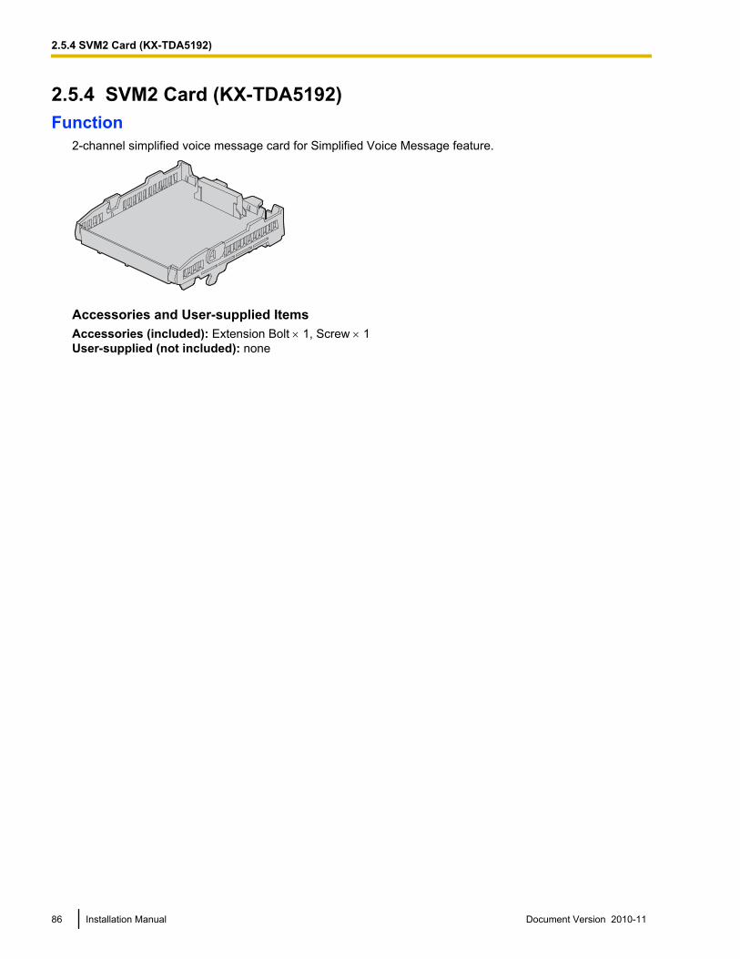
2.5.4 SVM2 Card (KX-TDA5192)Function
2-channel simplified voice message card for Simplified Voice Message feature.
Accessories and User-supplied ItemsAccessories (included): Extension Bolt ´ 1, Screw ´ 1User-supplied (not included): none
86 Installation Manual Document Version 2010-11
2.5.4 SVM2 Card (KX-TDA5192)
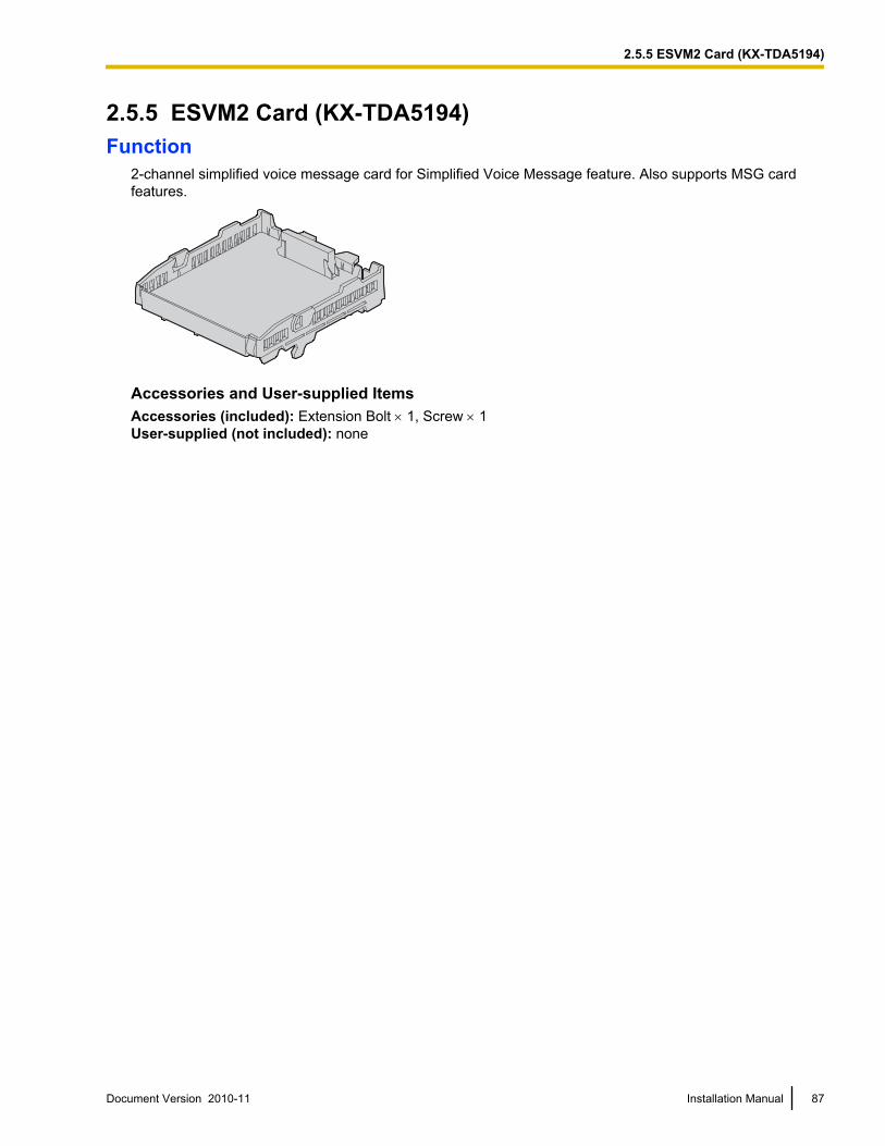
2.5.5 ESVM2 Card (KX-TDA5194)Function
2-channel simplified voice message card for Simplified Voice Message feature. Also supports MSG cardfeatures.
Accessories and User-supplied ItemsAccessories (included): Extension Bolt ´ 1, Screw ´ 1User-supplied (not included): none
Document Version 2010-11 Installation Manual 87
2.5.5 ESVM2 Card (KX-TDA5194)
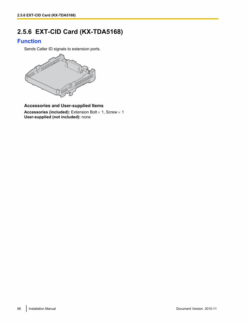
2.5.6 EXT-CID Card (KX-TDA5168)Function
Sends Caller ID signals to extension ports.
Accessories and User-supplied ItemsAccessories (included): Extension Bolt ´ 1, Screw ´ 1User-supplied (not included): none
88 Installation Manual Document Version 2010-11
2.5.6 EXT-CID Card (KX-TDA5168)
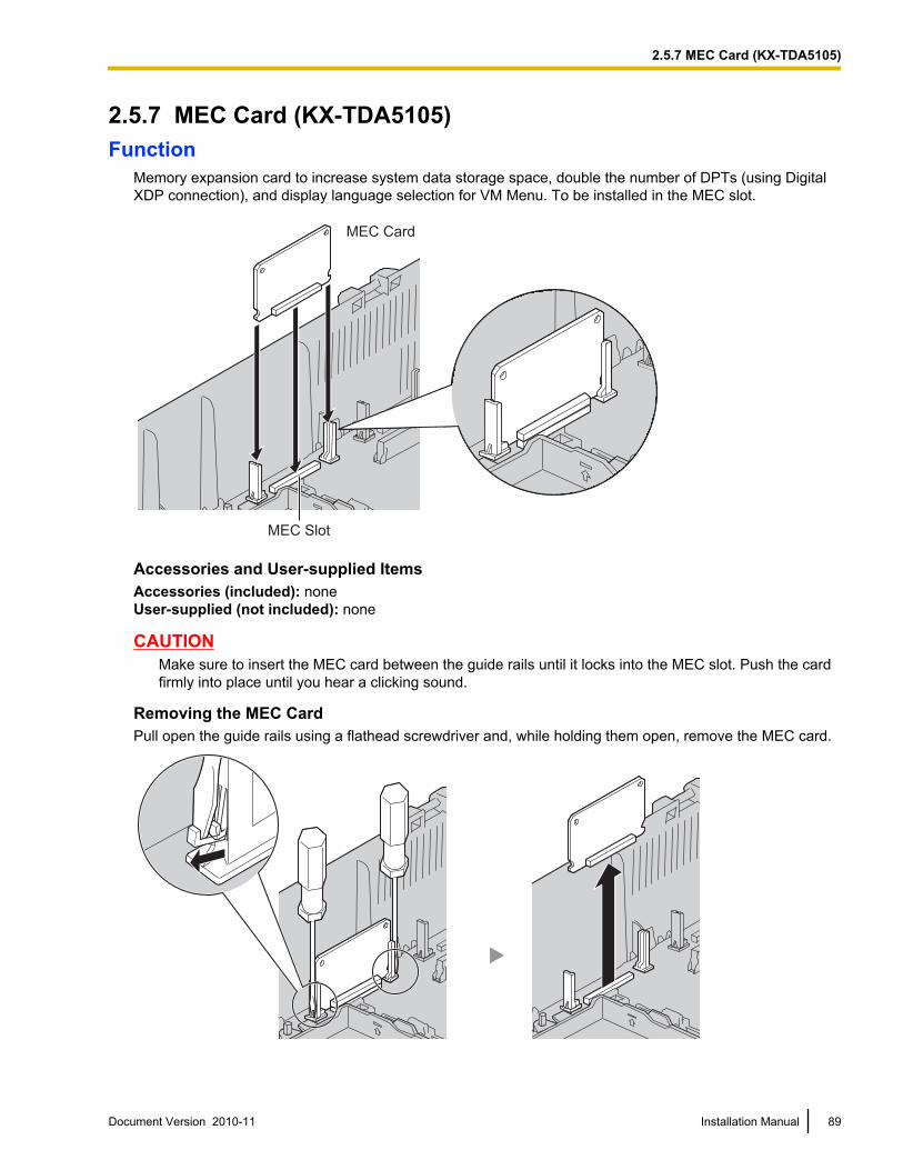
2.5.7 MEC Card (KX-TDA5105)Function
Memory expansion card to increase system data storage space, double the number of DPTs (using DigitalXDP connection), and display language selection for VM Menu. To be installed in the MEC slot.
MEC Card
MEC Slot
Accessories and User-supplied ItemsAccessories (included): noneUser-supplied (not included): none
CAUTIONMake sure to insert the MEC card between the guide rails until it locks into the MEC slot. Push the cardfirmly into place until you hear a clicking sound.
Removing the MEC CardPull open the guide rails using a flathead screwdriver and, while holding them open, remove the MEC card.
Document Version 2010-11 Installation Manual 89
2.5.7 MEC Card (KX-TDA5105)
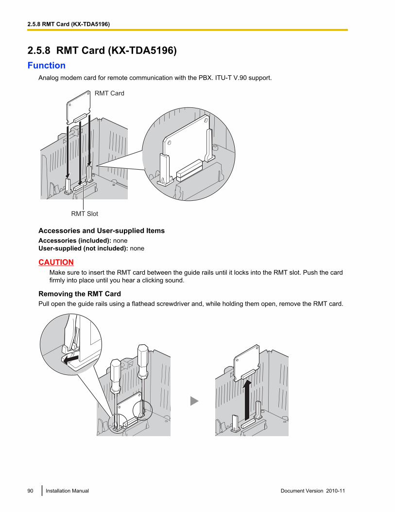
2.5.8 RMT Card (KX-TDA5196)Function
Analog modem card for remote communication with the PBX. ITU-T V.90 support.
RMT Slot
RMT Card
Accessories and User-supplied ItemsAccessories (included): noneUser-supplied (not included): none
CAUTIONMake sure to insert the RMT card between the guide rails until it locks into the RMT slot. Push the cardfirmly into place until you hear a clicking sound.
Removing the RMT CardPull open the guide rails using a flathead screwdriver and, while holding them open, remove the RMT card.
90 Installation Manual Document Version 2010-11
2.5.8 RMT Card (KX-TDA5196)
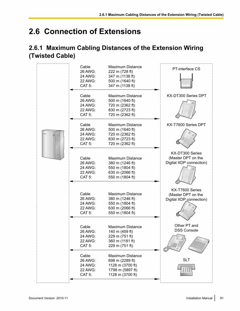
2.6 Connection of Extensions
2.6.1 Maximum Cabling Distances of the Extension Wiring(Twisted Cable)
Cable Maximum Distance
26 AWG: 222 m (728 ft)
24 AWG: 347 m (1138 ft)
22 AWG: 500 m (1640 ft)
CAT 5: 347 m (1138 ft)
Cable Maximum Distance
26 AWG: 140 m (459 ft)
24 AWG: 229 m (751 ft)
22 AWG: 360 m (1181 ft)
CAT 5: 229 m (751 ft)
Other PT and
DSS Console
Cable Maximum Distance
26 AWG: 698 m (2289 ft)
24 AWG: 1128 m (3700 ft)
22 AWG: 1798 m (5897 ft)
CAT 5: 1128 m (3700 ft)
SLT
Cable Maximum Distance
26 AWG: 380 m (1246 ft)
24 AWG: 550 m (1804 ft)
22 AWG: 630 m (2066 ft)
CAT 5: 550 m (1804 ft)
KX-DT300 Series
(Master DPT on the
Digital XDP connection)
Cable Maximum Distance
26 AWG: 380 m (1246 ft)
24 AWG: 550 m (1804 ft)
22 AWG: 630 m (2066 ft)
CAT 5: 550 m (1804 ft)
KX-T7600 Series
(Master DPT on the
Digital XDP connection)
Cable Maximum Distance
26 AWG: 500 m (1640 ft)
24 AWG: 720 m (2362 ft)
22 AWG: 830 m (2723 ft)
CAT 5: 720 m (2362 ft)
Cable Maximum Distance
26 AWG: 500 m (1640 ft)
24 AWG: 720 m (2362 ft)
22 AWG: 830 m (2723 ft)
CAT 5: 720 m (2362 ft)
KX-T7600 Series DPT
PT-interface CS
KX-DT300 Series DPT
Document Version 2010-11 Installation Manual 91
2.6.1 Maximum Cabling Distances of the Extension Wiring (Twisted Cable)
NoteThe maximum cabling distance may vary depending on the conditions.
PT-interfaceCS DPT APT
DSS Console
SLTKX-DT300/KX-T7600
seriesOther
Super Hybrid Ports(Main Board) ü ü ü ü ü ü
SLC4, SLC8 Cards ü
DLC4, DLC8 Cards ü ü ü ü
PLC4, PLC8 Cards ü ü
HLC4 Card ü ü ü ü ü
"ü" indicates that the extension card or Super Hybrid Ports support the terminal.
92 Installation Manual Document Version 2010-11
2.6.1 Maximum Cabling Distances of the Extension Wiring (Twisted Cable)
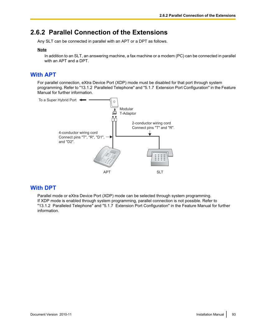
2.6.2 Parallel Connection of the ExtensionsAny SLT can be connected in parallel with an APT or a DPT as follows.
NoteIn addition to an SLT, an answering machine, a fax machine or a modem (PC) can be connected in parallelwith an APT and a DPT.
With APTFor parallel connection, eXtra Device Port (XDP) mode must be disabled for that port through systemprogramming. Refer to "13.1.2 Paralleled Telephone" and "5.1.7 Extension Port Configuration" in the FeatureManual for further information.
To a Super Hybrid Port
4-conductor wiring cord
Connect pins "T", "R", "D1",
and "D2".
2-conductor wiring cord
Connect pins "T" and "R".
SLTAPT
Modular
T-Adaptor
With DPTParallel mode or eXtra Device Port (XDP) mode can be selected through system programming.If XDP mode is enabled through system programming, parallel connection is not possible. Refer to"13.1.2 Paralleled Telephone" and "5.1.7 Extension Port Configuration" in the Feature Manual for furtherinformation.
Document Version 2010-11 Installation Manual 93
2.6.2 Parallel Connection of the Extensions
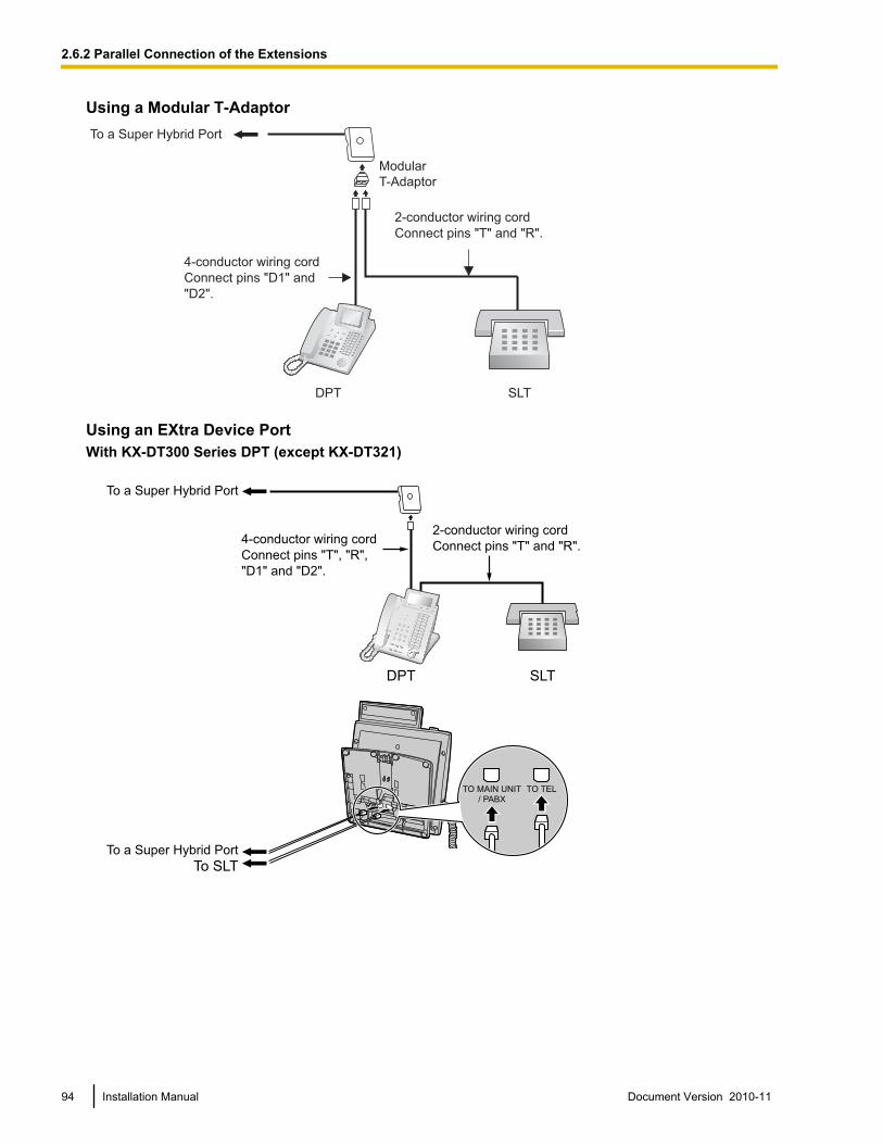
Using a Modular T-AdaptorTo a Super Hybrid Port
SLTDPT
Modular
T-Adaptor
4-conductor wiring cord
Connect pins "D1" and
"D2".
2-conductor wiring cord
Connect pins "T" and "R".
Using an EXtra Device PortWith KX-DT300 Series DPT (except KX-DT321)
TO MAIN UNIT/ PABX
TO TEL
To a Super Hybrid Port
DPT SLT
To a Super Hybrid Port
To SLT
2-conductor wiring cord
Connect pins "T" and "R".4-conductor wiring cord
Connect pins "T", "R",
"D1" and "D2".
94 Installation Manual Document Version 2010-11
2.6.2 Parallel Connection of the Extensions
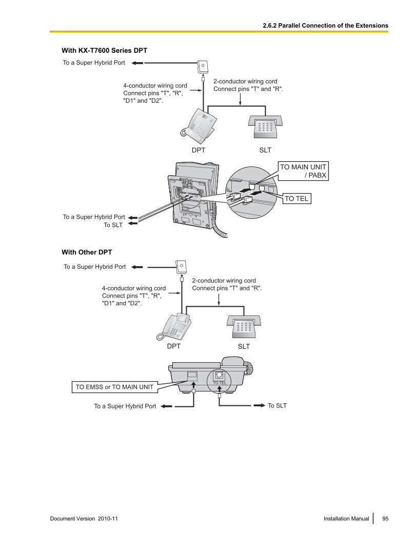
With KX-T7600 Series DPT
DPT SLT
To SLT
2-conductor wiring cord
Connect pins "T" and "R".4-conductor wiring cord
Connect pins "T", "R",
"D1" and "D2".
To a Super Hybrid Port
To a Super Hybrid Port
TO MAIN UNIT
/ PABX
TO TEL
With Other DPT
To a Super Hybrid Port
DPT SLT
To a Super Hybrid Port To SLT
2-conductor wiring cord
Connect pins "T" and "R".4-conductor wiring cord
Connect pins "T", "R",
"D1" and "D2".
TO TEL
TO EMSS or TO MAIN UNIT
Document Version 2010-11 Installation Manual 95
2.6.2 Parallel Connection of the Extensions
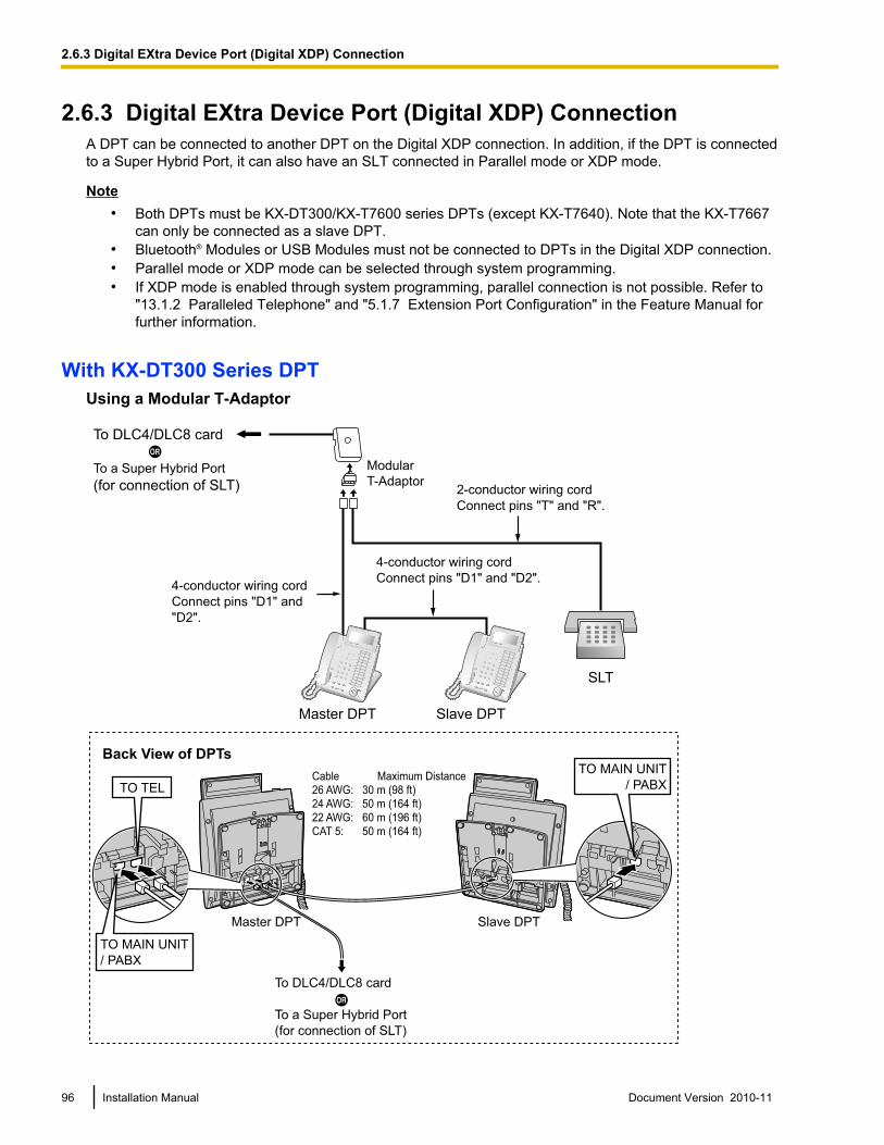
2.6.3 Digital EXtra Device Port (Digital XDP) ConnectionA DPT can be connected to another DPT on the Digital XDP connection. In addition, if the DPT is connectedto a Super Hybrid Port, it can also have an SLT connected in Parallel mode or XDP mode.
Note• Both DPTs must be KX-DT300/KX-T7600 series DPTs (except KX-T7640). Note that the KX-T7667
can only be connected as a slave DPT.• Bluetooth® Modules or USB Modules must not be connected to DPTs in the Digital XDP connection.• Parallel mode or XDP mode can be selected through system programming.• If XDP mode is enabled through system programming, parallel connection is not possible. Refer to
"13.1.2 Paralleled Telephone" and "5.1.7 Extension Port Configuration" in the Feature Manual forfurther information.
With KX-DT300 Series DPTUsing a Modular T-Adaptor
Slave DPTMaster DPT
Cable Maximum Distance
26 AWG: 30 m (98 ft)
24 AWG: 50 m (164 ft)
22 AWG: 60 m (196 ft)
CAT 5: 50 m (164 ft)
Back View of DPTs
TO MAIN UNIT
/ PABX
TO MAIN UNIT
/ PABX
TO TEL
4-conductor wiring cord
Connect pins "D1" and "D2".
Slave DPT
SLT
Master DPT
Modular
T-Adaptor
4-conductor wiring cord
Connect pins "D1" and
"D2".
2-conductor wiring cord
Connect pins "T" and "R".
To DLC4/DLC8 card
To a Super Hybrid Port
(for connection of SLT)
To DLC4/DLC8 card
To a Super Hybrid Port
(for connection of SLT)
96 Installation Manual Document Version 2010-11
2.6.3 Digital EXtra Device Port (Digital XDP) Connection
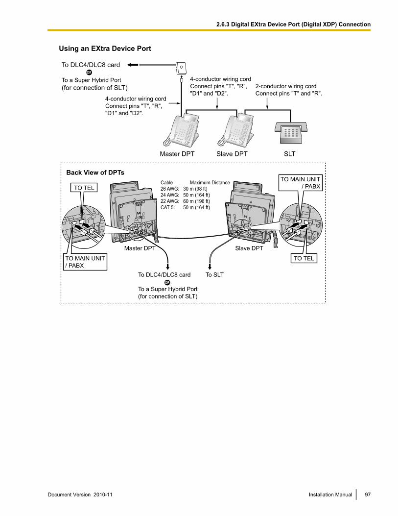
Using an EXtra Device Port
SLTMaster DPT Slave DPT
4-conductor wiring cord
Connect pins "T", "R",
"D1" and "D2".
2-conductor wiring cord
Connect pins "T" and "R".4-conductor wiring cord
Connect pins "T", "R",
"D1" and "D2".
To DLC4/DLC8 card
To a Super Hybrid Port
(for connection of SLT)
To SLT
Slave DPTMaster DPT
Cable Maximum Distance
26 AWG: 30 m (98 ft)
24 AWG: 50 m (164 ft)
22 AWG: 60 m (196 ft)
CAT 5: 50 m (164 ft)
Back View of DPTs
TO MAIN UNIT
/ PABX
TO MAIN UNIT
/ PABX
TO TEL
TO TEL
To DLC4/DLC8 card
To a Super Hybrid Port
(for connection of SLT)
Document Version 2010-11 Installation Manual 97
2.6.3 Digital EXtra Device Port (Digital XDP) Connection
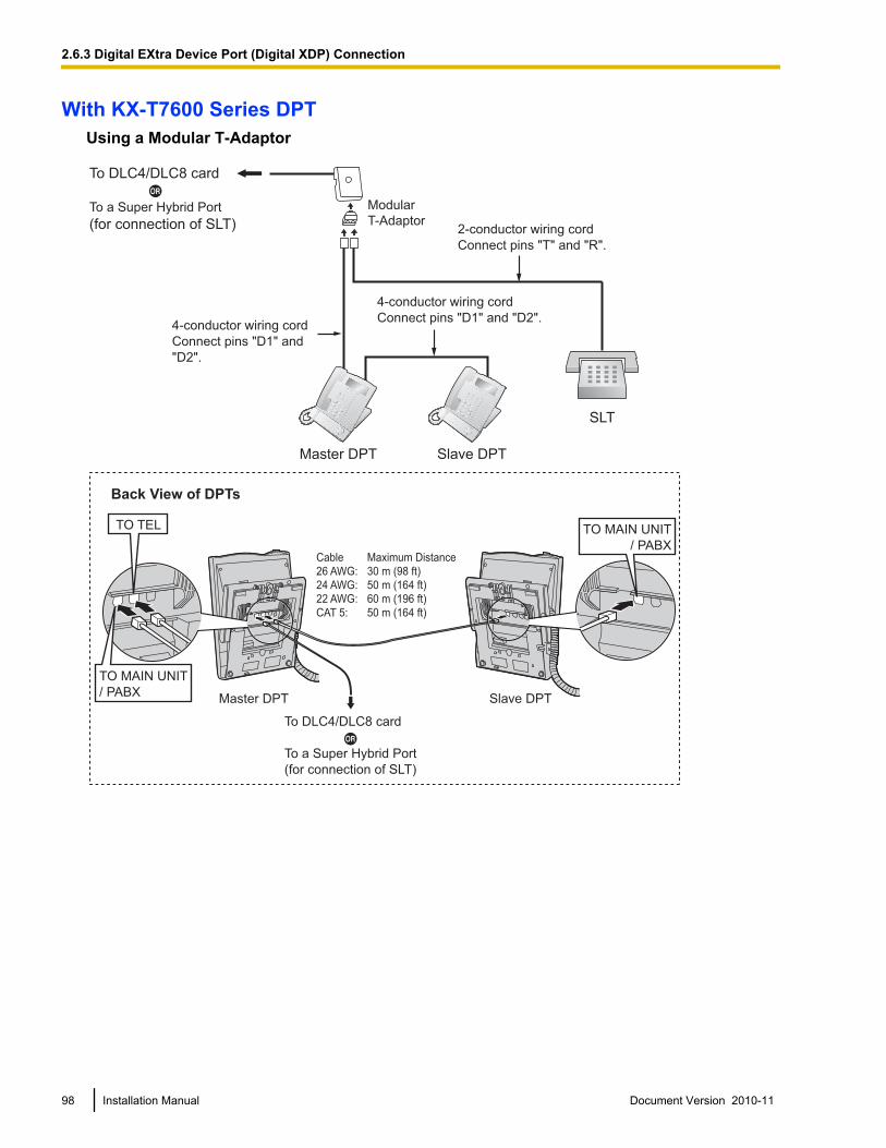
With KX-T7600 Series DPTUsing a Modular T-Adaptor
To DLC4/DLC8 card
To a Super Hybrid Port
(for connection of SLT)
4-conductor wiring cord
Connect pins "D1" and "D2".
Slave DPT
SLT
Master DPT
Modular
T-Adaptor
4-conductor wiring cord
Connect pins "D1" and
"D2".
2-conductor wiring cord
Connect pins "T" and "R".
Slave DPTMaster DPT
TO MAIN UNIT
/ PABX
TO TEL
TO MAIN UNIT
/ PABX
Cable Maximum Distance
26 AWG: 30 m (98 ft)
24 AWG: 50 m (164 ft)
22 AWG: 60 m (196 ft)
CAT 5: 50 m (164 ft)
Back View of DPTs
To DLC4/DLC8 card
To a Super Hybrid Port
(for connection of SLT)
98 Installation Manual Document Version 2010-11
2.6.3 Digital EXtra Device Port (Digital XDP) Connection
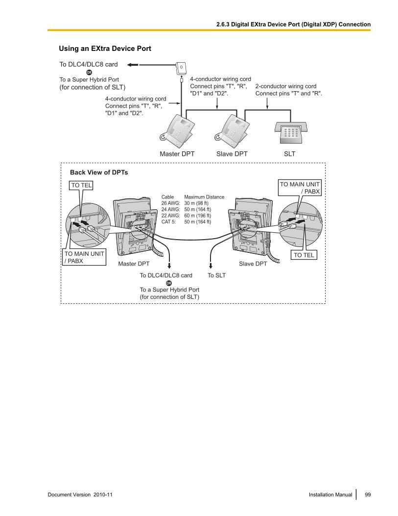
Using an EXtra Device Port
SLTMaster DPT Slave DPT
4-conductor wiring cord
Connect pins "T", "R",
"D1" and "D2".
2-conductor wiring cord
Connect pins "T" and "R".4-conductor wiring cord
Connect pins "T", "R",
"D1" and "D2".
Slave DPTMaster DPT
To SLT
TO MAIN UNIT
/ PABX
TO TEL
TO TEL
TO MAIN UNIT
/ PABX
Cable Maximum Distance
26 AWG: 30 m (98 ft)
24 AWG: 50 m (164 ft)
22 AWG: 60 m (196 ft)
CAT 5: 50 m (164 ft)
Back View of DPTs
To DLC4/DLC8 card
To a Super Hybrid Port
(for connection of SLT)
To DLC4/DLC8 card
To a Super Hybrid Port
(for connection of SLT)
Document Version 2010-11 Installation Manual 99
2.6.3 Digital EXtra Device Port (Digital XDP) Connection
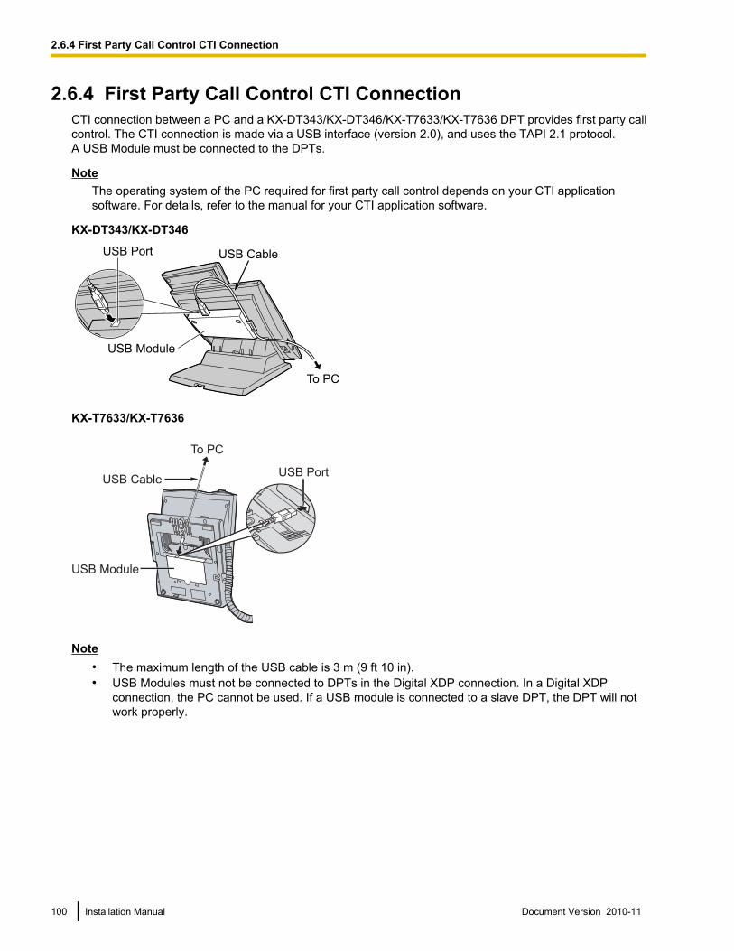
2.6.4 First Party Call Control CTI ConnectionCTI connection between a PC and a KX-DT343/KX-DT346/KX-T7633/KX-T7636 DPT provides first party callcontrol. The CTI connection is made via a USB interface (version 2.0), and uses the TAPI 2.1 protocol.A USB Module must be connected to the DPTs.
NoteThe operating system of the PC required for first party call control depends on your CTI applicationsoftware. For details, refer to the manual for your CTI application software.
KX-DT343/KX-DT346
USB Port USB Cable
USB Module
To PC
KX-T7633/KX-T7636
USB Cable
To PC
ULL
USB Port
USB Module
Note• The maximum length of the USB cable is 3 m (9 ft 10 in).• USB Modules must not be connected to DPTs in the Digital XDP connection. In a Digital XDP
connection, the PC cannot be used. If a USB module is connected to a slave DPT, the DPT will notwork properly.
100 Installation Manual Document Version 2010-11
2.6.4 First Party Call Control CTI Connection
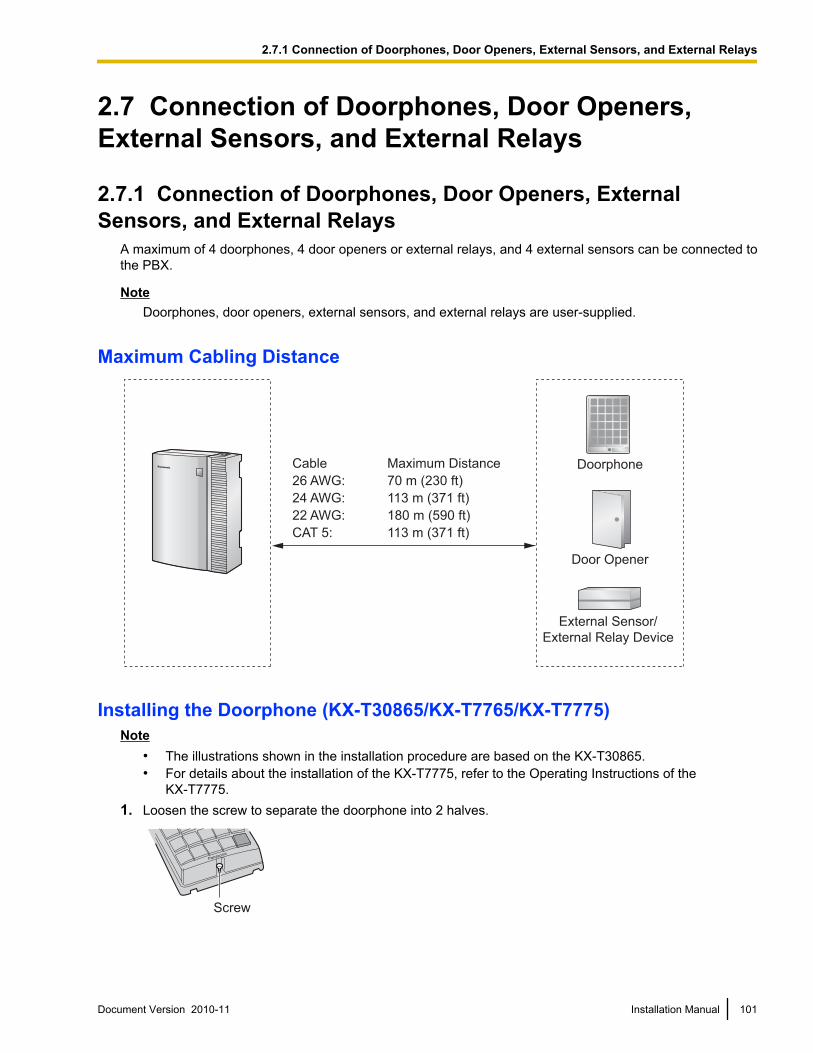
2.7 Connection of Doorphones, Door Openers,External Sensors, and External Relays
2.7.1 Connection of Doorphones, Door Openers, ExternalSensors, and External Relays
A maximum of 4 doorphones, 4 door openers or external relays, and 4 external sensors can be connected tothe PBX.
NoteDoorphones, door openers, external sensors, and external relays are user-supplied.
Maximum Cabling Distance
Cable Maximum Distance
26 AWG: 70 m (230 ft)
24 AWG: 113 m (371 ft)
22 AWG: 180 m (590 ft)
CAT 5: 113 m (371 ft)
Doorphone
Door Opener
External Sensor/
External Relay Device
Installing the Doorphone (KX-T30865/KX-T7765/KX-T7775)Note
• The illustrations shown in the installation procedure are based on the KX-T30865.• For details about the installation of the KX-T7775, refer to the Operating Instructions of the
KX-T7775.1. Loosen the screw to separate the doorphone into 2 halves.
Panaso
nic
Screw
Document Version 2010-11 Installation Manual 101
2.7.1 Connection of Doorphones, Door Openers, External Sensors, and External Relays
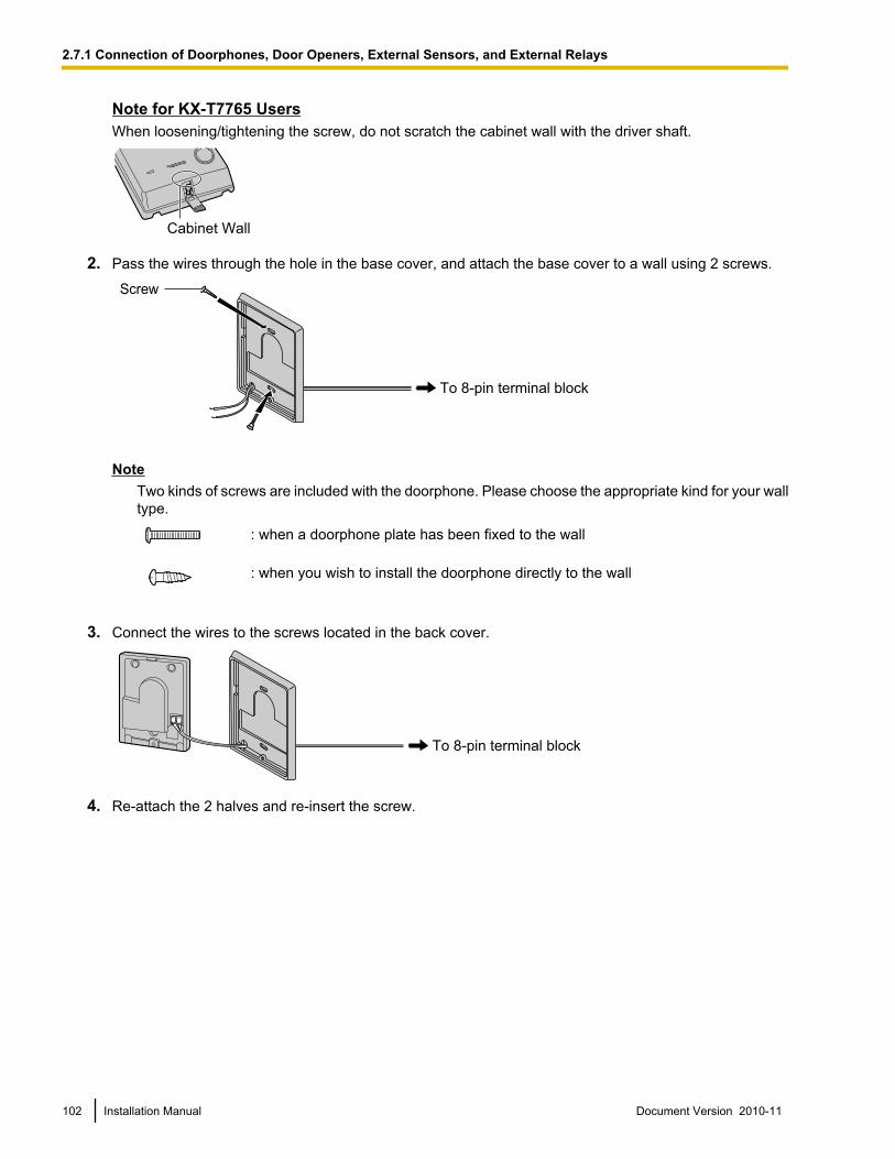
Note for KX-T7765 UsersWhen loosening/tightening the screw, do not scratch the cabinet wall with the driver shaft.
Cabinet Wall
2. Pass the wires through the hole in the base cover, and attach the base cover to a wall using 2 screws.
Screw
To 8-pin terminal block
NoteTwo kinds of screws are included with the doorphone. Please choose the appropriate kind for your walltype.
: when a doorphone plate has been fixed to the wall
: when you wish to install the doorphone directly to the wall
3. Connect the wires to the screws located in the back cover.
To 8-pin terminal block
4. Re-attach the 2 halves and re-insert the screw.
102 Installation Manual Document Version 2010-11
2.7.1 Connection of Doorphones, Door Openers, External Sensors, and External Relays
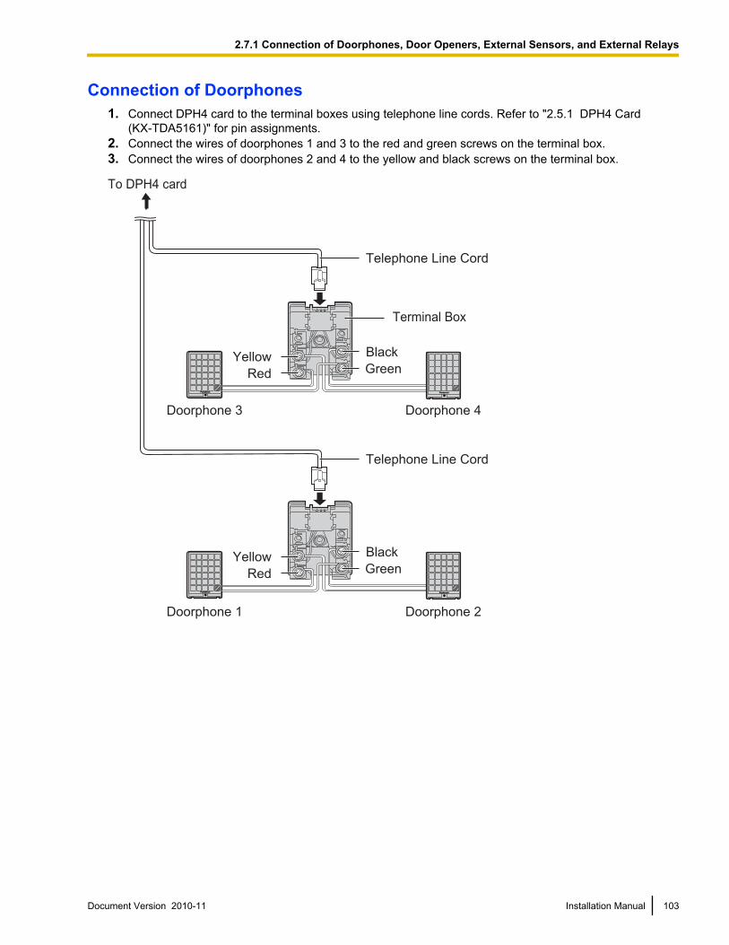
Connection of Doorphones1. Connect DPH4 card to the terminal boxes using telephone line cords. Refer to "2.5.1 DPH4 Card
(KX-TDA5161)" for pin assignments.2. Connect the wires of doorphones 1 and 3 to the red and green screws on the terminal box.3. Connect the wires of doorphones 2 and 4 to the yellow and black screws on the terminal box.
PanasonicPanasonic PanasonicPanasonic
Yellow
Red
Black
Telephone Line Cord
Telephone Line Cord
Green
Doorphone 3 Doorphone 4
Doorphone 1 Doorphone 2
To DPH4 card
Terminal Box
PanasonicPanasonic PanasonicPanasonic
Yellow
Red
Black
Green
Document Version 2010-11 Installation Manual 103
2.7.1 Connection of Doorphones, Door Openers, External Sensors, and External Relays
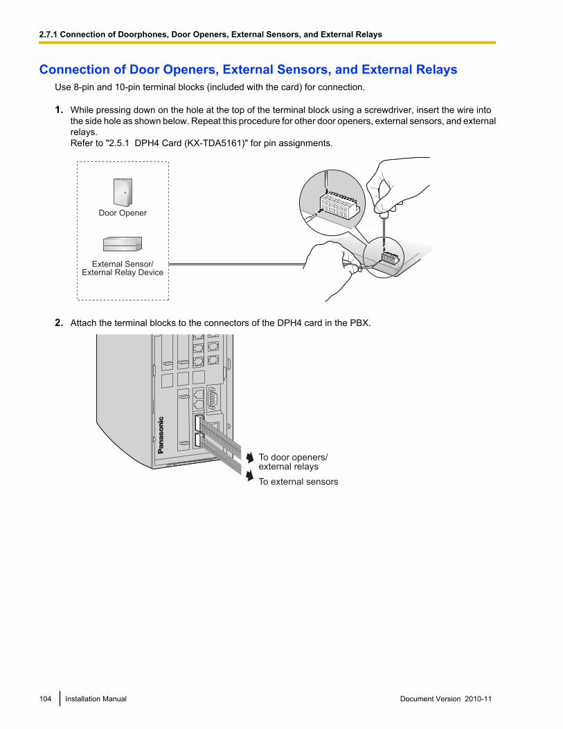
Connection of Door Openers, External Sensors, and External RelaysUse 8-pin and 10-pin terminal blocks (included with the card) for connection.
1. While pressing down on the hole at the top of the terminal block using a screwdriver, insert the wire intothe side hole as shown below. Repeat this procedure for other door openers, external sensors, and externalrelays.Refer to "2.5.1 DPH4 Card (KX-TDA5161)" for pin assignments.
Door Opener
External Sensor/External Relay Device
2. Attach the terminal blocks to the connectors of the DPH4 card in the PBX.
To external sensors
To door openers/external relays
104 Installation Manual Document Version 2010-11
2.7.1 Connection of Doorphones, Door Openers, External Sensors, and External Relays
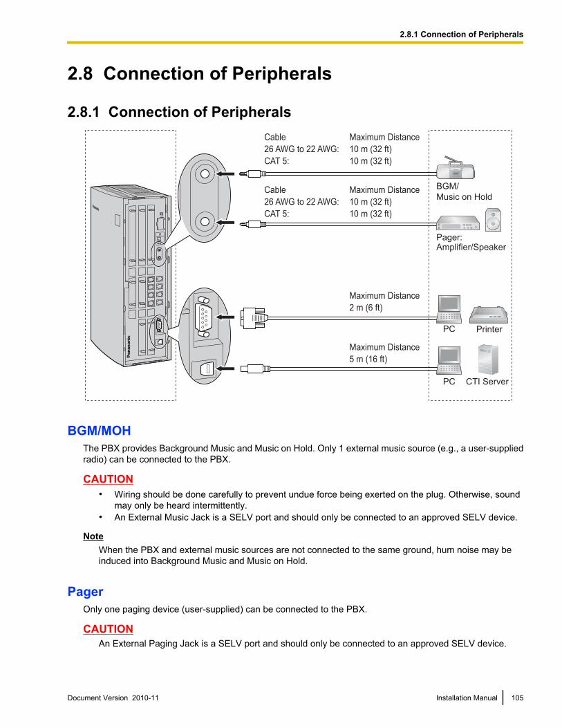
2.8 Connection of Peripherals
2.8.1 Connection of Peripherals
BGM/
Music on Hold
Pager:Amplifier/Speaker
PC Printer
Cable Maximum Distance
26 AWG to 22 AWG: 10 m (32 ft)
CAT 5: 10 m (32 ft)
Cable Maximum Distance
26 AWG to 22 AWG: 10 m (32 ft)
CAT 5: 10 m (32 ft)
Maximum Distance
2 m (6 ft)
Maximum Distance
5 m (16 ft)
PC CTI Server
BGM/MOHThe PBX provides Background Music and Music on Hold. Only 1 external music source (e.g., a user-suppliedradio) can be connected to the PBX.
CAUTION• Wiring should be done carefully to prevent undue force being exerted on the plug. Otherwise, sound
may only be heard intermittently.• An External Music Jack is a SELV port and should only be connected to an approved SELV device.
NoteWhen the PBX and external music sources are not connected to the same ground, hum noise may beinduced into Background Music and Music on Hold.
PagerOnly one paging device (user-supplied) can be connected to the PBX.
CAUTIONAn External Paging Jack is a SELV port and should only be connected to an approved SELV device.
Document Version 2010-11 Installation Manual 105
2.8.1 Connection of Peripherals
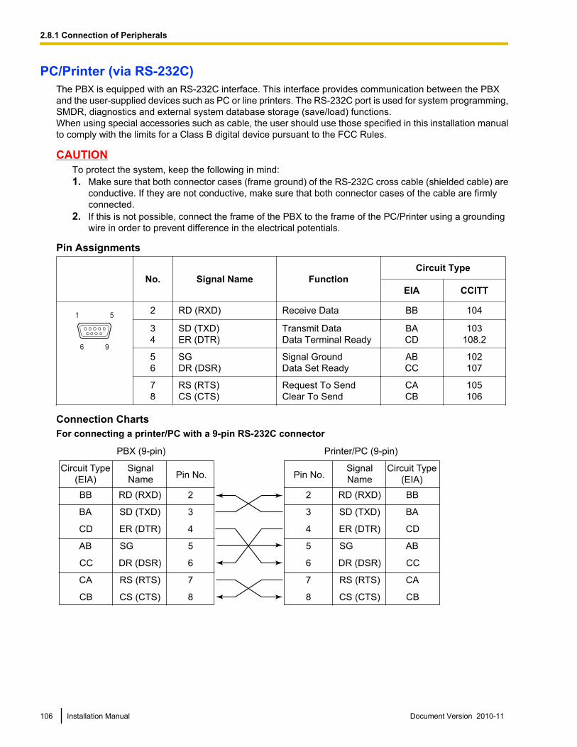
PC/Printer (via RS-232C)The PBX is equipped with an RS-232C interface. This interface provides communication between the PBXand the user-supplied devices such as PC or line printers. The RS-232C port is used for system programming,SMDR, diagnostics and external system database storage (save/load) functions.When using special accessories such as cable, the user should use those specified in this installation manualto comply with the limits for a Class B digital device pursuant to the FCC Rules.
CAUTIONTo protect the system, keep the following in mind:1. Make sure that both connector cases (frame ground) of the RS-232C cross cable (shielded cable) are
conductive. If they are not conductive, make sure that both connector cases of the cable are firmlyconnected.
2. If this is not possible, connect the frame of the PBX to the frame of the PC/Printer using a groundingwire in order to prevent difference in the electrical potentials.
Pin Assignments
No. Signal Name FunctionCircuit Type
EIA CCITT
6 9
1 52 RD (RXD) Receive Data BB 104
34
SD (TXD)ER (DTR)
Transmit DataData Terminal Ready
BACD
103108.2
56
SGDR (DSR)
Signal GroundData Set Ready
ABCC
102107
78
RS (RTS)CS (CTS)
Request To SendClear To Send
CACB
105106
Connection ChartsFor connecting a printer/PC with a 9-pin RS-232C connector
PBX (9-pin) Printer/PC (9-pin)
Circuit Type
(EIA)
Signal
NamePin No. Pin No.
Signal
Name
Circuit Type
(EIA)
BB RD (RXD) 2
BA SD (TXD) 3
CD ER (DTR) 4
AB SG 5
CC DR (DSR) 6
CA RS (RTS) 7
CB CS (CTS) 8
2 RD (RXD) BB
3 SD (TXD) BA
4 ER (DTR) CD
5 SG AB
6 DR (DSR) CC
7 RS (RTS) CA
8 CS (CTS) CB
106 Installation Manual Document Version 2010-11
2.8.1 Connection of Peripherals
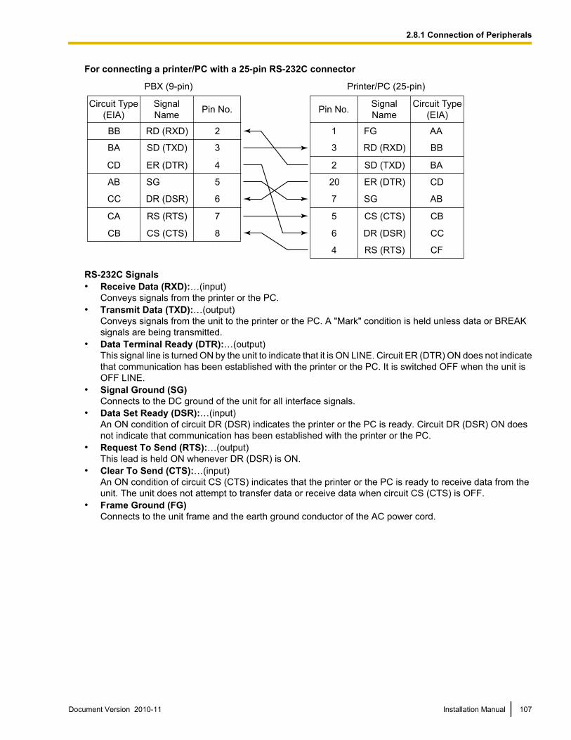
For connecting a printer/PC with a 25-pin RS-232C connector
PBX (9-pin) Printer/PC (25-pin)
Circuit Type
(EIA)
Signal
NamePin No.
Signal
Name
Circuit Type
(EIA)
BB RD (RXD) 2
BA SD (TXD) 3
CD ER (DTR) 4
AB SG 5
CC DR (DSR) 6
CA RS (RTS) 7
CB CS (CTS) 8
1 FG AA
3 RD (RXD) BB
2 SD (TXD) BA
20 ER (DTR) CD
7 SG AB
5 CS (CTS) CB
6 DR (DSR) CC
CF4 RS (RTS)
Pin No.
RS-232C Signals• Receive Data (RXD):…(input)
Conveys signals from the printer or the PC.• Transmit Data (TXD):…(output)
Conveys signals from the unit to the printer or the PC. A "Mark" condition is held unless data or BREAKsignals are being transmitted.
• Data Terminal Ready (DTR):…(output)This signal line is turned ON by the unit to indicate that it is ON LINE. Circuit ER (DTR) ON does not indicatethat communication has been established with the printer or the PC. It is switched OFF when the unit isOFF LINE.
• Signal Ground (SG)Connects to the DC ground of the unit for all interface signals.
• Data Set Ready (DSR):…(input)An ON condition of circuit DR (DSR) indicates the printer or the PC is ready. Circuit DR (DSR) ON doesnot indicate that communication has been established with the printer or the PC.
• Request To Send (RTS):…(output)This lead is held ON whenever DR (DSR) is ON.
• Clear To Send (CTS):…(input)An ON condition of circuit CS (CTS) indicates that the printer or the PC is ready to receive data from theunit. The unit does not attempt to transfer data or receive data when circuit CS (CTS) is OFF.
• Frame Ground (FG)Connects to the unit frame and the earth ground conductor of the AC power cord.
Document Version 2010-11 Installation Manual 107
2.8.1 Connection of Peripherals
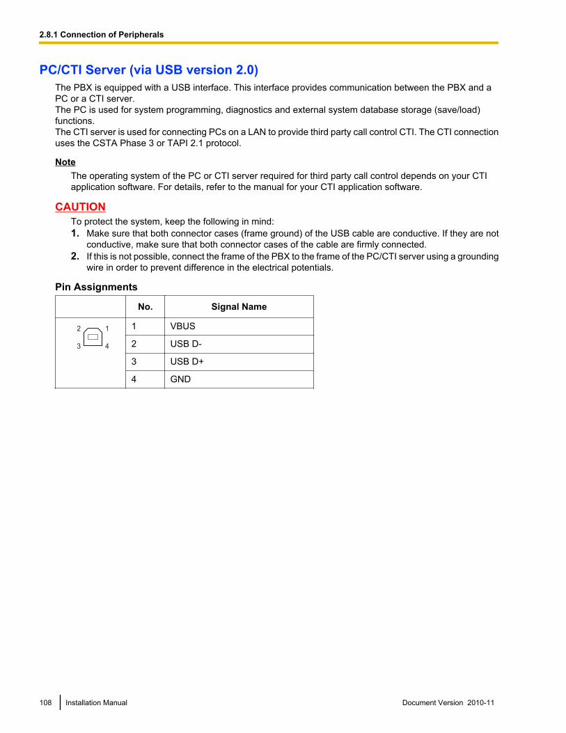
PC/CTI Server (via USB version 2.0)The PBX is equipped with a USB interface. This interface provides communication between the PBX and aPC or a CTI server.The PC is used for system programming, diagnostics and external system database storage (save/load)functions.The CTI server is used for connecting PCs on a LAN to provide third party call control CTI. The CTI connectionuses the CSTA Phase 3 or TAPI 2.1 protocol.
NoteThe operating system of the PC or CTI server required for third party call control depends on your CTIapplication software. For details, refer to the manual for your CTI application software.
CAUTIONTo protect the system, keep the following in mind:1. Make sure that both connector cases (frame ground) of the USB cable are conductive. If they are not
conductive, make sure that both connector cases of the cable are firmly connected.2. If this is not possible, connect the frame of the PBX to the frame of the PC/CTI server using a grounding
wire in order to prevent difference in the electrical potentials.
Pin Assignments
No. Signal Name
2
3
1
4
1 VBUS
2 USB D-
3 USB D+
4 GND
108 Installation Manual Document Version 2010-11
2.8.1 Connection of Peripherals
2.9 Power Failure Connections
2.9.1 Power Failure ConnectionsWhen the power supply to the PBX fails, power failure transfer (PFT) will switch from the current connectionto the Power Failure Connection. Refer to "13.1.9 Power Failure Transfer" in the Feature Manual for furtherinformation.
Using Analog CO Line Card and Super Hybrid PortsIn the event of power failure, SLTs connected to Ports 1 and 2 of the Super Hybrid Ports (on the Main Board)are automatically connected to PFT ports 1 and 2 of the first LCOT4 card (installed in the least slot number).
NoteEven when the power returns, the conversation established during power failure will be maintained.
Document Version 2010-11 Installation Manual 109
2.9.1 Power Failure Connections
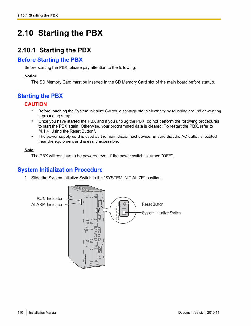
2.10 Starting the PBX
2.10.1 Starting the PBXBefore Starting the PBX
Before starting the PBX, please pay attention to the following:
NoticeThe SD Memory Card must be inserted in the SD Memory Card slot of the main board before startup.
Starting the PBXCAUTION
• Before touching the System Initialize Switch, discharge static electricity by touching ground or wearinga grounding strap.
• Once you have started the PBX and if you unplug the PBX, do not perform the following proceduresto start the PBX again. Otherwise, your programmed data is cleared. To restart the PBX, refer to"4.1.4 Using the Reset Button".
• The power supply cord is used as the main disconnect device. Ensure that the AC outlet is locatednear the equipment and is easily accessible.
NoteThe PBX will continue to be powered even if the power switch is turned "OFF".
System Initialization Procedure1. Slide the System Initialize Switch to the "SYSTEM INITIALIZE" position.
RUN Indicator
ALARM Indicator Reset Button
System Initialize Switch
110 Installation Manual Document Version 2010-11
2.10.1 Starting the PBX
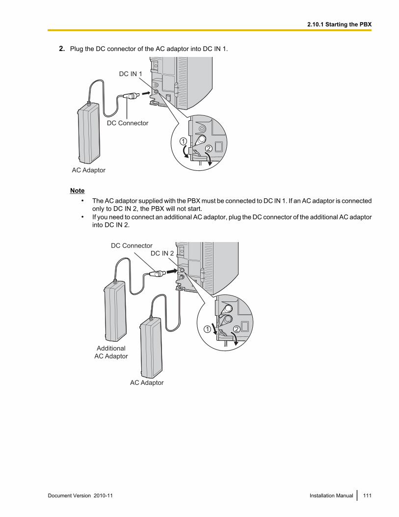
2. Plug the DC connector of the AC adaptor into DC IN 1.
AC Adaptor
DC Connector
DC IN 1
21
Note• The AC adaptor supplied with the PBX must be connected to DC IN 1. If an AC adaptor is connected
only to DC IN 2, the PBX will not start.• If you need to connect an additional AC adaptor, plug the DC connector of the additional AC adaptor
into DC IN 2.
DC Connector
Additional
AC Adaptor
DC IN 2
AC Adaptor
1 2
Document Version 2010-11 Installation Manual 111
2.10.1 Starting the PBX
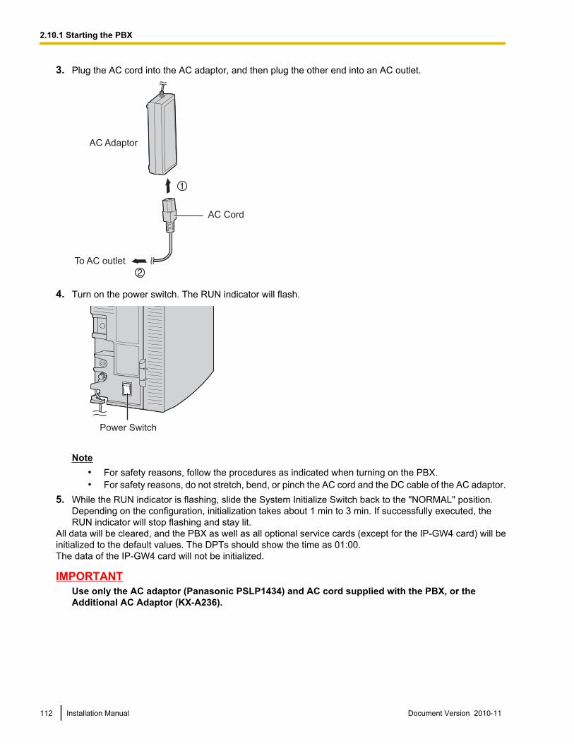
3. Plug the AC cord into the AC adaptor, and then plug the other end into an AC outlet.
AC Adaptor
AC Cord
To AC outlet
4. Turn on the power switch. The RUN indicator will flash.
Power Switch
Note• For safety reasons, follow the procedures as indicated when turning on the PBX.• For safety reasons, do not stretch, bend, or pinch the AC cord and the DC cable of the AC adaptor.
5. While the RUN indicator is flashing, slide the System Initialize Switch back to the "NORMAL" position.Depending on the configuration, initialization takes about 1 min to 3 min. If successfully executed, theRUN indicator will stop flashing and stay lit.
All data will be cleared, and the PBX as well as all optional service cards (except for the IP-GW4 card) will beinitialized to the default values. The DPTs should show the time as 01:00.The data of the IP-GW4 card will not be initialized.
IMPORTANTUse only the AC adaptor (Panasonic PSLP1434) and AC cord supplied with the PBX, or theAdditional AC Adaptor (KX-A236).
112 Installation Manual Document Version 2010-11
2.10.1 Starting the PBX
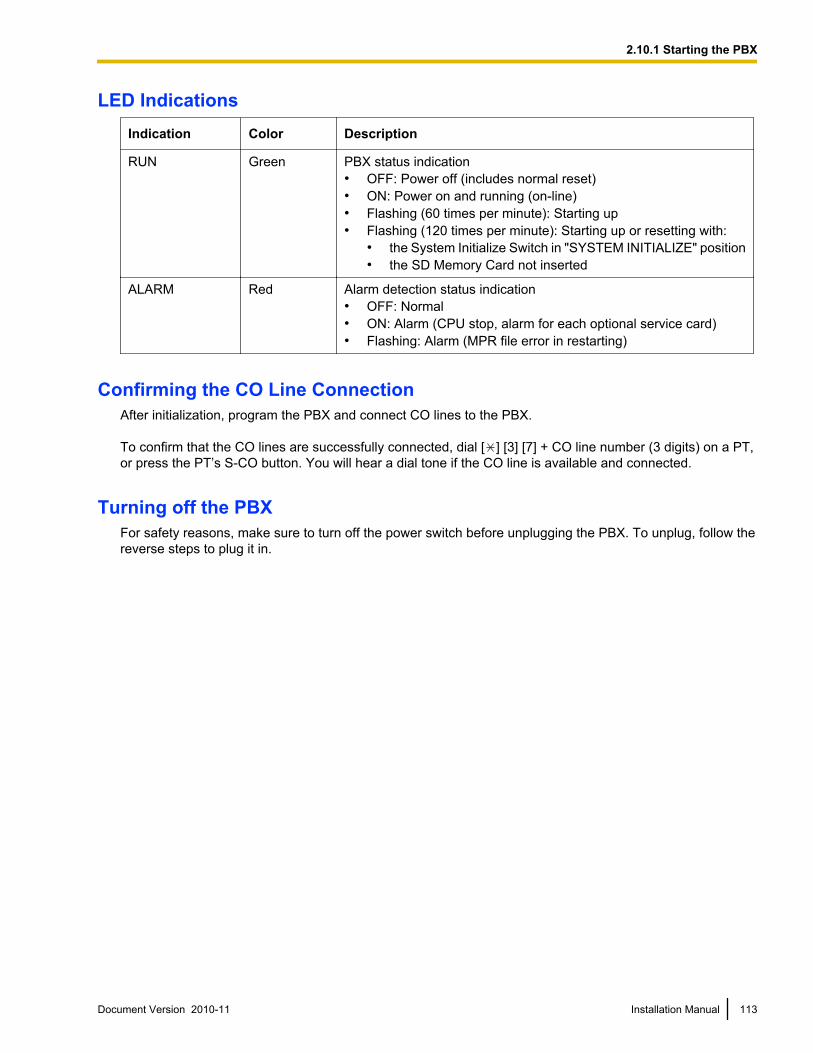
LED IndicationsIndication Color Description
RUN Green PBX status indication• OFF: Power off (includes normal reset)• ON: Power on and running (on-line)• Flashing (60 times per minute): Starting up• Flashing (120 times per minute): Starting up or resetting with:
• the System Initialize Switch in "SYSTEM INITIALIZE" position• the SD Memory Card not inserted
ALARM Red Alarm detection status indication• OFF: Normal• ON: Alarm (CPU stop, alarm for each optional service card)• Flashing: Alarm (MPR file error in restarting)
Confirming the CO Line ConnectionAfter initialization, program the PBX and connect CO lines to the PBX.
To confirm that the CO lines are successfully connected, dial [ ] [3] [7] + CO line number (3 digits) on a PT,or press the PT’s S-CO button. You will hear a dial tone if the CO line is available and connected.
Turning off the PBXFor safety reasons, make sure to turn off the power switch before unplugging the PBX. To unplug, follow thereverse steps to plug it in.
Document Version 2010-11 Installation Manual 113
2.10.1 Starting the PBX

114 Installation Manual Document Version 2010-11
2.10.1 Starting the PBX

Section 3
Guide for the PBX PC Programming Software
This section explains the installation and structure of thePBX PC Programming Software.
Document Version 2010-11 Installation Manual 115
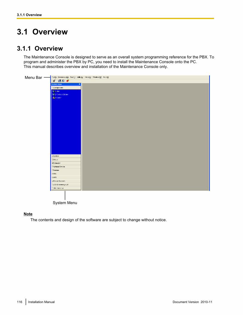
3.1 Overview
3.1.1 OverviewThe Maintenance Console is designed to serve as an overall system programming reference for the PBX. Toprogram and administer the PBX by PC, you need to install the Maintenance Console onto the PC.This manual describes overview and installation of the Maintenance Console only.
Menu Bar
System Menu
NoteThe contents and design of the software are subject to change without notice.
116 Installation Manual Document Version 2010-11
3.1.1 Overview
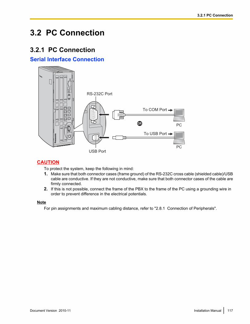
3.2 PC Connection
3.2.1 PC ConnectionSerial Interface Connection
PC
PC
To USB Port
To COM Port
USB Port
RS-232C Port
CAUTIONTo protect the system, keep the following in mind:1. Make sure that both connector cases (frame ground) of the RS-232C cross cable (shielded cable)/USB
cable are conductive. If they are not conductive, make sure that both connector cases of the cable arefirmly connected.
2. If this is not possible, connect the frame of the PBX to the frame of the PC using a grounding wire inorder to prevent difference in the electrical potentials.
NoteFor pin assignments and maximum cabling distance, refer to "2.8.1 Connection of Peripherals".
Document Version 2010-11 Installation Manual 117
3.2.1 PC Connection
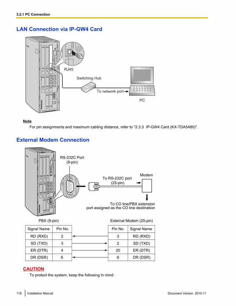
LAN Connection via IP-GW4 Card
PC
Switching Hub
To network port
RJ45
NoteFor pin assignments and maximum cabling distance, refer to "2.3.3 IP-GW4 Card (KX-TDA5480)".
External Modem Connection
To CO line/PBX extensionport assigned as the CO line destination
ModemTo RS-232C port
(25-pin)
External Modem (25-pin)PBX (9-pin)
Signal Name Pin No. Signal Name
RD (RXD)3
SD (TXD)2
ER (DTR)20
DR (DSR)6
2RD (RXD)
3SD (TXD)
4 ER (DTR)
6DR (DSR)
Pin No.
RS-232C Port
(9-pin)
CAUTIONTo protect the system, keep the following in mind:
118 Installation Manual Document Version 2010-11
3.2.1 PC Connection
1. Make sure that both connector cases (frame ground) of the RS-232C straight cable (shielded cable)are conductive. If they are not conductive, make sure that both connector cases of the cable are firmlyconnected.
2. If this is not possible, connect the frame of the PBX to the frame of the PC using a grounding wire inorder to prevent difference in the electrical potentials.
After connecting the PBX and the external modem, set the power switch of the external modem to "ON", thenthe external modem will be initialized with the default values.The following AT command settings may be required for the modem:• The Data Terminal Ready (DTR) signal should be ignored.• The Data Terminal Equipment (DTE)/Modem flow control should be turned off.• Data compression should be disabled.• Error Correction is not necessary.
Note• An AT command (for initialization, enabling automatic answer, etc.) can only be programmed by the
Maintenance Console. "AT&F" is stored as the default value.• For more information about the AT command, refer to the external modem’s instructions.
Document Version 2010-11 Installation Manual 119
3.2.1 PC Connection

3.3 Installation of the PBX PC Programming Software
3.3.1 Installing and Starting the Maintenance ConsoleSystem Requirements
Required Operating System• Microsoft® Windows® XP, Windows Vista® Business, or Windows 7 Professional operating system
Minimum Hardware Requirements• HDD: 100 MB of available hard disk space
Recommended Display Settings• Screen resolution: XGA (1024 ´ 768)• DPI setting: Normal size (96 DPI)
Installing the Maintenance ConsoleNote
• Make sure to install and use the latest version of the Maintenance Console.• To install or uninstall the software on a PC running Windows XP Professional, you must be logged in
as a user in either the "Administrators" or "Power Users" group.• To install or uninstall the software on a PC running Windows Vista Business or Windows 7 Professional,
you must be logged in as a user in the "Administrators" group.• To connect the PC to the PBX via USB, the KX-TDA USB driver must be installed. Follow the
instructions of the wizard to install the KX-TDA USB driver. When the PBX is first connected to the PCvia USB, you may be asked to select the appropriate USB driver. Browse for and select the KX-TDAUSB driver that was installed previously.
1. Copy the setup file of the Maintenance Console to your PC.2. Double-click the setup file to run the installer.3. Follow the on-screen instructions provided by the installation wizard.
Starting the Maintenance Console and Assigning the Basic Items (QuickSetup)
When you start the Maintenance Console with the Installer Level Programmer Code and connect to the PBXfor the first time after initialization (with the factory default setting), Quick Setup will launch automatically. DuringQuick Setup, you will set up the basic items. For details about the basic items, refer to "14.1.2 Quick Setup"in the Feature Manual.
1. Connect the PC to the PBX with a USB cable.
2. Start the Maintenance Console from the Start menu.
3. "Information before programming" appears.a. Carefully read this important additional information, which includes updates to this and other
manuals.b. Click OK to close this window.
120 Installation Manual Document Version 2010-11
3.3.1 Installing and Starting the Maintenance Console
4. a. Enter the Installer Level Programmer Code (default: INSTALLER).
NoteThere are 2 other Programmer Codes with limited authorization: Administrator Level (default:ADMIN), and User Level (default: USER).
b. Click OK.
5. Click Connect.
6. a. Select KX-TDA50 from PBX Model.b. Select the USB tab.
NoteTo connect to the PBX via USB, the KX-TDA USB driver must be installed on the PC, asexplained above in "Installing the Maintenance Console".
c. Enter the system password for installer (default: 1234).d. Click Connect.
7. Follow the instructions of the Quick Setup wizard and assign the basic items (Quick Setup).You may now begin programming the PBX.
Notice• During a long programming session, it is highly recommended that you periodically save the system
data to the SD Memory Card. If the PBX undergoes a sudden power failure or if the system is reset forsome reason, all the system data in RAM will be lost. However, if system data has been saved to theSD Memory Card, it can be easily restored.To save the system data to the SD Memory Card, (1) click the "SD Memory Backup" icon beforeresetting the PBX or turning off the power, or (2) exit the Maintenance Console so that the PBXautomatically saves the system data.
• When programming PBX data which can be displayed on a proprietary telephone (PT) (extensionnames, group names, System Speed Dialing names, etc.), it is possible to enter characters which
Document Version 2010-11 Installation Manual 121
3.3.1 Installing and Starting the Maintenance Console
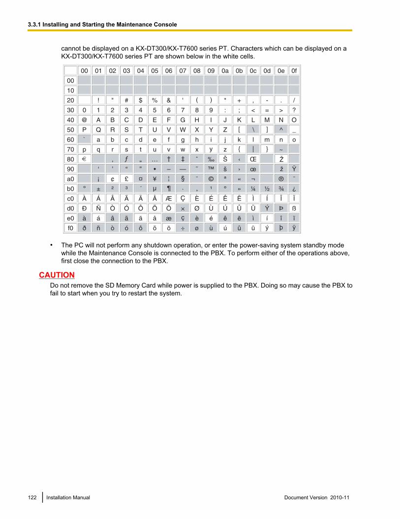
cannot be displayed on a KX-DT300/KX-T7600 series PT. Characters which can be displayed on aKX-DT300/KX-T7600 series PT are shown below in the white cells.
• The PC will not perform any shutdown operation, or enter the power-saving system standby modewhile the Maintenance Console is connected to the PBX. To perform either of the operations above,first close the connection to the PBX.
CAUTIONDo not remove the SD Memory Card while power is supplied to the PBX. Doing so may cause the PBX tofail to start when you try to restart the system.
122 Installation Manual Document Version 2010-11
3.3.1 Installing and Starting the Maintenance Console
Section 4
Troubleshooting
This section provides information on the PBX andtelephone troubleshooting.
Document Version 2010-11 Installation Manual 123
4.1 Troubleshooting
4.1.1 InstallationPROBLEM PROBABLE CAUSE SOLUTION
Extension does not operate. Bad extension card. • Exchange the card for a knownworking one.
Bad connection between thePBX and telephone.
• Take the telephone and plug it into thesame extension port using a shorttelephone cord. If the telephoneworks, then the connection betweenthe PBX and the telephone must berepaired.
A telephone with an A-A1relay is connected.
• Use a 2-wire cord.• Set the A-A1 relay switch of the
telephone to the "OUT" or "OFF"position.
Bad telephone. • Take the telephone and plug it intoanother extension port that is working.If the telephone does not work,replace the telephone.
The number of terminalequipment exceeds thecapacity of the PBX with thesupplied AC adaptor only.
• Connect an additional AC adaptor.
The PBX does not operateproperly.
• Press the Reset Button (refer to"4.1.4 Using the Reset Button").
• Turn off the power switch, and thenturn it back on.
• Turn off the power switch, and thenunplug the PBX. After 5 minutes, plugthe PBX back in and turn the powerswitch back on.
Noise on external paging. Induced noise on the wirebetween the PBX and theamplifier.
• Use a shielded cable as theconnection wire between the PBX andamplifier. A short shielded cable isrecommended.
Distorted external music. Excessive input level fromexternal music source.
• Decrease the output level of theexternal music source by using thevolume control on the music source.
Alternate Calling—Ring/Voiceand Live Call Screening (LCS)do not function as set whenusing a Wireless Phone(KX-T7880/KX-T7885/KX-TD7894/KX-TD7895).
Voice-calling mode andHands-free mode with LCSare not available withWireless Phones.
• Switch the calling mode to ring-calling.• Set the LCS mode to "Private".
124 Installation Manual Document Version 2010-11
4.1.1 Installation
PROBLEM PROBABLE CAUSE SOLUTION
The ALARM indicator on thefront of the cabinet turns onred.
A major system error occursin the PBX.
• See the error log using theMaintenance Console (refer to"4.1.5 Troubleshooting by Error Log").
Document Version 2010-11 Installation Manual 125
4.1.1 Installation
4.1.2 ConnectionConnection between the PBX and a PT:
Connection between the PBX and an SLT:
Connection between the PBX and an SLT that is polarity-sensitive:
CAUSE
The T/R is connected to the D1/D2.
SOLUTION
Use the correct cord (the
inner 2 wires are for T/R and
the outer 2 wires are for
D1/D2).D1TR
D2
D1 TR D2
PBX
PBX
PBX
Extension
CAUSE
The T/R is connected to the D1/D2.
SOLUTION
Use the correct cord (the
inner 2 wires are for T/R).
•D1TR
D2
TR
Extension
CAUSE
The "T" is connected to the "R".
SOLUTION
Reverse the connections of
the T/R.
D1TR
D2
TR
Extension
Can you dial
an extension?
(Continued on the next page.)
No
Yes
If a telephone equipped
with an A-A1 relay is
connected to the PBX,
set the A-A1 relay switch
of the telephone to "OFF".
126 Installation Manual Document Version 2010-11
4.1.2 Connection
Connection between the central office and the PBX:
CAUSE
CO line is connected to the T2/T1.
CO line is connected to the T2/R1.
SOLUTION
Reconnect the CO line to
the T1/R1 or T2/R2 of the
telephone jack using
2-conductor wiring.T2 R1T1R2
CO line PBX
PBXCO line
T2 R1T1R2
(Continued from the
previous page.)
Can you dial
out on a
CO line?
No
Document Version 2010-11 Installation Manual 127
4.1.2 Connection
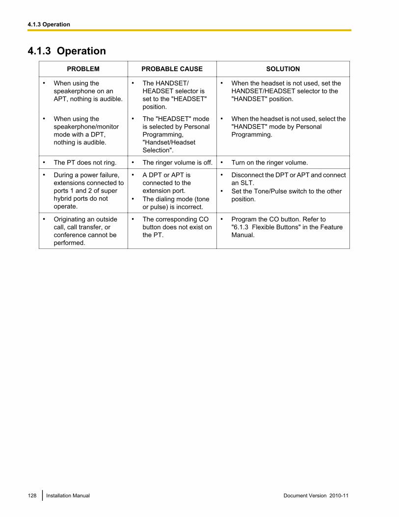
4.1.3 OperationPROBLEM PROBABLE CAUSE SOLUTION
• When using thespeakerphone on anAPT, nothing is audible.
• The HANDSET/HEADSET selector isset to the "HEADSET"position.
• When the headset is not used, set theHANDSET/HEADSET selector to the"HANDSET" position.
• When using thespeakerphone/monitormode with a DPT,nothing is audible.
• The "HEADSET" modeis selected by PersonalProgramming,"Handset/HeadsetSelection".
• When the headset is not used, select the"HANDSET" mode by PersonalProgramming.
• The PT does not ring. • The ringer volume is off. • Turn on the ringer volume.
• During a power failure,extensions connected toports 1 and 2 of superhybrid ports do notoperate.
• A DPT or APT isconnected to theextension port.
• The dialing mode (toneor pulse) is incorrect.
• Disconnect the DPT or APT and connectan SLT.
• Set the Tone/Pulse switch to the otherposition.
• Originating an outsidecall, call transfer, orconference cannot beperformed.
• The corresponding CObutton does not exist onthe PT.
• Program the CO button. Refer to"6.1.3 Flexible Buttons" in the FeatureManual.
128 Installation Manual Document Version 2010-11
4.1.3 Operation
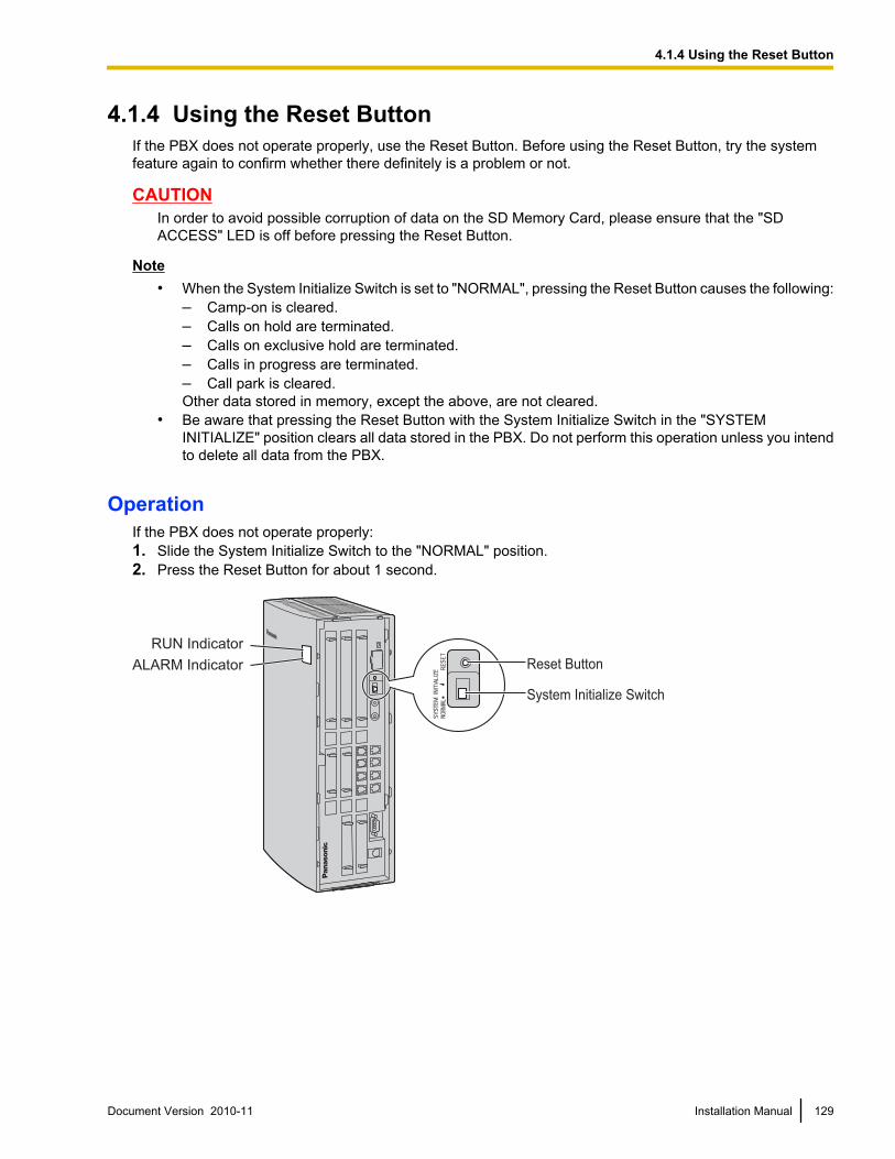
4.1.4 Using the Reset ButtonIf the PBX does not operate properly, use the Reset Button. Before using the Reset Button, try the systemfeature again to confirm whether there definitely is a problem or not.
CAUTIONIn order to avoid possible corruption of data on the SD Memory Card, please ensure that the "SDACCESS" LED is off before pressing the Reset Button.
Note• When the System Initialize Switch is set to "NORMAL", pressing the Reset Button causes the following:
– Camp-on is cleared.– Calls on hold are terminated.– Calls on exclusive hold are terminated.– Calls in progress are terminated.– Call park is cleared.Other data stored in memory, except the above, are not cleared.
• Be aware that pressing the Reset Button with the System Initialize Switch in the "SYSTEMINITIALIZE" position clears all data stored in the PBX. Do not perform this operation unless you intendto delete all data from the PBX.
OperationIf the PBX does not operate properly:1. Slide the System Initialize Switch to the "NORMAL" position.2. Press the Reset Button for about 1 second.
RUN Indicator
ALARM Indicator Reset Button
System Initialize Switch
Document Version 2010-11 Installation Manual 129
4.1.4 Using the Reset Button
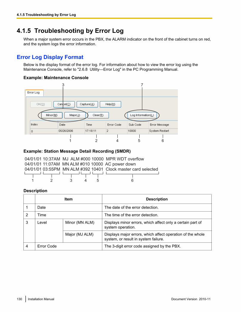
4.1.5 Troubleshooting by Error LogWhen a major system error occurs in the PBX, the ALARM indicator on the front of the cabinet turns on red,and the system logs the error information.
Error Log Display FormatBelow is the display format of the error log. For information about how to view the error log using theMaintenance Console, refer to "2.6.8 Utility—Error Log" in the PC Programming Manual.
Example: Maintenance Console
1 2 4 5 6
3 7
Example: Station Message Detail Recording (SMDR)
04/01/01 10:37AM MJ ALM #000 10000 MPR WDT overflow
04/01/01 11:07AM MN ALM #010 10000 AC power down
04/01/01 03:55PM MN ALM #392 10401 Clock master card selected
1 2 3 4 5 6
Description
Item Description
1 Date The date of the error detection.
2 Time The time of the error detection.
3 Level Minor (MN ALM) Displays minor errors, which affect only a certain part ofsystem operation.
Major (MJ ALM) Displays major errors, which affect operation of the wholesystem, or result in system failure.
4 Error Code The 3-digit error code assigned by the PBX.
130 Installation Manual Document Version 2010-11
4.1.5 Troubleshooting by Error Log
Item Description
5 Sub Code The 5-digit sub code of the relevant hardware (1XXYY).• 1: Cabinet number• XX: Slot number
00 to 11(00: MPR card slot; 01: Super hybrid ports; 02 to 11: Slotsfor optional service cards)
• YY: Physical port number– For optional service cards:
Physical port number (01 to 16) will be displayed.– For optional service cards that are installed in Slots
08 to 11:Sub slot number 1 + port number (1 to 4) will bedisplayed as follows:• Sub slot 1: 11 to 14
NoteWhen there are no parameters for the slot and physicalport numbers, XX and YY will be displayed as "00".Example: Sub code for MPR card = 10000
6 Error Message A description of the error.
7 Log Information Displays probable causes of the errors and their solutions.
Document Version 2010-11 Installation Manual 131
4.1.5 Troubleshooting by Error Log

132 Installation Manual Document Version 2010-11
4.1.5 Troubleshooting by Error Log

Section 5
Appendix
Document Version 2010-11 Installation Manual 133

5.1 Revision History
5.1.1 PSMPR Software File Version 1.1xxxNew Options
• System Components Table
– KX-TDA5105 Memory Expansion Card (MEC)
Changed Contents• 1.3.3 System Capacity
134 Installation Manual Document Version 2010-11
5.1.1 PSMPR Software File Version 1.1xxx
5.1.2 PSMPR Software File Version 2.0xxxNew Options
• System Components Table
– KX-TDA5920 SD Memory Card for Software Upgrade to Enhanced Version
Changed Contents• 1.3.3 System Capacity• 2.7.1 Connection of Doorphones, Door Openers, External Sensors, and External Relays
Document Version 2010-11 Installation Manual 135
5.1.2 PSMPR Software File Version 2.0xxx
5.1.3 PSMPR Software File Version 3.0xxxNew Options
• System Components Table
– KX-TDA5192 2-Channel Simplified Voice Message Card (SVM2)
136 Installation Manual Document Version 2010-11
5.1.3 PSMPR Software File Version 3.0xxx
5.1.4 PSMPR Software File Version 4.0xxxNew Options
• System Components Table
– KX-TDA5470 4-Channel VoIP Extension Card (IP-EXT4)
Changed Contents• 1.3.3 System Capacity• 2.3.3 IP-GW4 Card (KX-TDA5480)• 3.2.1 PC Connection
Document Version 2010-11 Installation Manual 137
5.1.4 PSMPR Software File Version 4.0xxx
5.1.5 PSMPR Software File Version 5.0xxxNew Options
• System Components Table
– KX-TDA5194 2-Channel Simplified Voice Message Card (ESVM2)
– KX-TDA5450 4-Channel SIP Trunk Card (SIP-GW4)
– KX-TDA5451 4-Channel VoIP DSP Card (SIP-DSP4)
– KX-T0151 2-Channel Cell Station Unit Using a Super Hybrid Port or a HLC/DLC Card for 2.4GHz Portable Station
– KX-T0155 DECT 6.0 2-Channel Cell Station Unit Using a Super Hybrid Port or a HLC/DLCCard for DECT 6.0 Portable Station
– KX-T0158 DECT 6.0 8-Channel Cell Station Unit Using a Super Hybrid Port or a HLC/DLCCard for DECT 6.0 Portable Station
– KX-T7765 Doorphone
– KX-T7775 Doorphone
New Contents• 2.5.5 ESVM2 Card (KX-TDA5194)• 2.7 Connection of Doorphones, Door Openers, External Sensors, and External Relays
Changed Contents• 1.3.3 System Capacity• 2.7.1 Connection of Doorphones, Door Openers, External Sensors, and External Relays• 3.3.1 Installing and Starting the Maintenance Console
138 Installation Manual Document Version 2010-11
5.1.5 PSMPR Software File Version 5.0xxx

Index
Document Version 2010-11 Installation Manual 139
Numerics2-Channel Message Card (KX-TDA5191) 21, 852-Channel Simplified Voice Message Card(KX-TDA5192) 21, 862-Channel Simplified Voice Message Card(KX-TDA5194) 22, 874-Channel SIP Trunk Card (KX-TDA5450) 22, 694-Channel VoIP DSP Card (KX-TDA5451) 22, 714-Channel VoIP Extension Card (KX-TDA5470) 22, 794-Channel VoIP Gateway Card (KX-TDA5480) 22, 674-Port Analog Trunk Card (KX-TDA5180) 21, 654-Port Caller ID Card (KX-TDA5193) 22, 664-Port Digital Extension Card (KX-TDA5171) 21, 734-Port Doorphone Card (KX-TDA5161) 21, 814-Port Hybrid Extension Card (KX-TDA5170) 21, 724-Port Proprietary Extension Card (KX-TDA5175) 21, 754-Port Single Line Telephone Extension Card(KX-TDA5173) 21, 748-Channel Echo Canceller Card (KX-TDA5166) 21, 848-Port Digital Extension Card (KX-TDA5172) 21, 768-Port Proprietary Extension Card (KX-TDA5176) 21, 788-Port Single Line Telephone Extension Card(KX-TDA5174) 21, 77
AAbout the software version of your PBX 11AC Adaptor Selection 29Additional AC Adaptor (KX-A236) 22Appendix 133
BBasic System Construction 18BGM 105
CCable Distance 91Cable Handling 48Calculation Example 27Changed Contents 134, 135, 137, 138Characteristics 25CID4 Card (KX-TDA5193) 66CO Line Connection 113CO Line, Maximum Number 26Components, System 2Connection Diagram for External Sensors and ExternalRelays 83Connection Diagram, System 19Connector Types 53Cover, Closing 37Cover, Opening 36CTI Server Connection (via USB version 2.0) 108CTI—First Party Call Control 100CTI—Third Party Call Control 108
DDigital EXtra Device Port (Digital XDP) Connection 96Digital XDP 96Digital XDP Connection, Using a Modular T-Adaptor 96, 98
Digital XDP Connection, Using an EXtra DevicePort 97, 99DLC4 Card (KX-TDA5171) 73DLC8 Card (KX-TDA5172) 76Door Opener 81, 101Doorphone 81, 101DPH4 Card (KX-TDA5161) 81
EECHO8 Card (KX-TDA5166) 84Error Log 130ESVM2 Card (KX-TDA5194) 87EXT-CID Card (KX-TDA5168) 88Extension Caller ID Card (KX-TDA5168) 21, 88External Relay 81, 101External Sensor 81, 101EXtra Device Port (XDP) Mode 93, 96
FFerrite Core 54First Party Call Control CTI Connection 100Frame Ground Connection 41Front Cover, Attachment 37Front Cover, Removal 37
HHLC4 Card (KX-TDA5170) 72
IInstallation Precautions 32IP-EXT4 Card (KX-TDA5470) 79IP-GW4 Card (KX-TDA5480) 67
KKX-A236 (Additional AC Adaptor) 22KX-TDA50 Maintenance Console, Overview 116KX-TDA50 Maintenance Console, Password Security 10KX-TDA5105 (Memory Expansion Card) 21, 89KX-TDA5161 (4-Port Doorphone Card) 21, 81KX-TDA5166 (8-Channel Echo Canceller Card) 21, 84KX-TDA5168 (Extension Caller ID Card) 21, 88KX-TDA5170 (4-Port Hybrid Extension Card) 21, 72KX-TDA5171 (4-Port Digital Extension Card) 21, 73KX-TDA5172 (8-Port Digital Extension Card) 21, 76KX-TDA5173 (4-Port Single Line Telephone ExtensionCard) 21, 74KX-TDA5174 (8-Port Single Line Telephone ExtensionCard) 21, 77KX-TDA5175 (4-Port Proprietary Extension Card) 21, 75KX-TDA5176 (8-Port Proprietary Extension Card) 21, 78KX-TDA5180 (4-Port Analog Trunk Card) 21, 65KX-TDA5191 (2-Channel Message Card) 21, 85KX-TDA5192 (2-Channel Simplified Voice MessageCard) 21, 86KX-TDA5193 (4-Port Caller ID Card) 22, 66KX-TDA5194 (2-Channel Simplified Voice MessageCard) 22, 87KX-TDA5196 (Remote Card) 22, 90KX-TDA5450 (4-Channel SIP Trunk Card) 22, 69
140 Installation Manual Document Version 2010-11
Index
KX-TDA5451 (4-Channel VoIP DSP Card) 22, 71KX-TDA5470 (4-Channel VoIP Extension Card) 22, 79KX-TDA5480 (4-Channel VoIP Gateway Card) 22, 67KX-TDA5920 (SD Memory Card for Software Upgrade toEnhanced Version) 22
LLCOT4 Card (KX-TDA5180) 65LED Indications, PBX 113
MMain Unit 18Main Unit, Construction 18Maintenance Console 116Maintenance Console, Connection 117Maintenance Console, Installation 120Maintenance Console, Quick Setup 120Maintenance Console, System Requirements 120Master DPT, Digital XDP 96Maximum CO Line and VoIP Line 26Maximum Terminal Equipment 26MEC Card (KX-TDA5105) 89MEC Card Calculation 27Memory Expansion Card (KX-TDA5105) 21, 89MOH 105MSG2 Card (KX-TDA5191) 85
NNames and Locations 35New Options 134, 135, 136, 137, 138
OOptional Equipment 21Optional Service Card, Installation 43Optional Service Card, Removal 51
PPager 105Panasonic Proprietary Telephones, Compatible 3Panasonic Proprietary Telephones, Incompatible 3Parallel Connection of the Extensions 93Parallel Connection, Using a Modular T-Adaptor 94Parallel Connection, Using an EXtra Device Port 94Password Security 10PC Connection (via RS-232C) 106PC Connection (via USB version 2.0) 108PLC4 Card (KX-TDA5175) 75PLC8 Card (KX-TDA5176) 78Power Failure Connections 109Printer Connection (via RS-232C) 106PSMPR Software File Version 1.1xxx 134PSMPR Software File Version 2.0xxx 135PSMPR Software File Version 3.0xxx 136PSMPR Software File Version 4.0xxx 137PSMPR Software File Version 5.0xxx 138
QQuick Setup 120
RRemote Card (KX-TDA5196) 22, 90Reset Button 129Revision History 134RMT Card (KX-TDA5196) 90RUN Indicator 110
SSafety Installation Instructions 32SD Memory Card 39SD Memory Card for Software Upgrade to Enhanced Version(KX-TDA5920) 22SIP-DSP4 Card (KX-TDA5451) 71SIP-GW4 Card (KX-TDA5450) 69Slave DPT, Digital XDP 96SLC4 Card (KX-TDA5173) 74SLC8 Card (KX-TDA5174) 77Slot Position 42Slot Restrictions 42Specifications 23Specifications, Characteristics 25Specifications, General Description 23Specifications, System Capacity 26Starting the PBX 110Surge Protector Installation 62SVM2 Card (KX-TDA5192) 86System Capacity 26System Components Table 2System Connection Diagram 19System Initialization Procedure 110System Initialize Switch 110, 129System Requirements 120
TTerminal Equipment, Maximum Number 26Troubleshooting, by Error Log 130Troubleshooting, Connection 126Troubleshooting, Installation 124Troubleshooting, Operation 128Troubleshooting, Using the Reset Button 129Turning off the PBX 113
UUnpacking 34
VVoIP Line, Maximum Number 26
WWall Mounting (AC Adaptor) 58Wall Mounting (KX-TDA50) 55Wall Mounting Reference (AC Adaptor) 61Wall Mounting Reference (KX-TDA50) 55Wiring Precautions 33
Document Version 2010-11 Installation Manual 141
Index
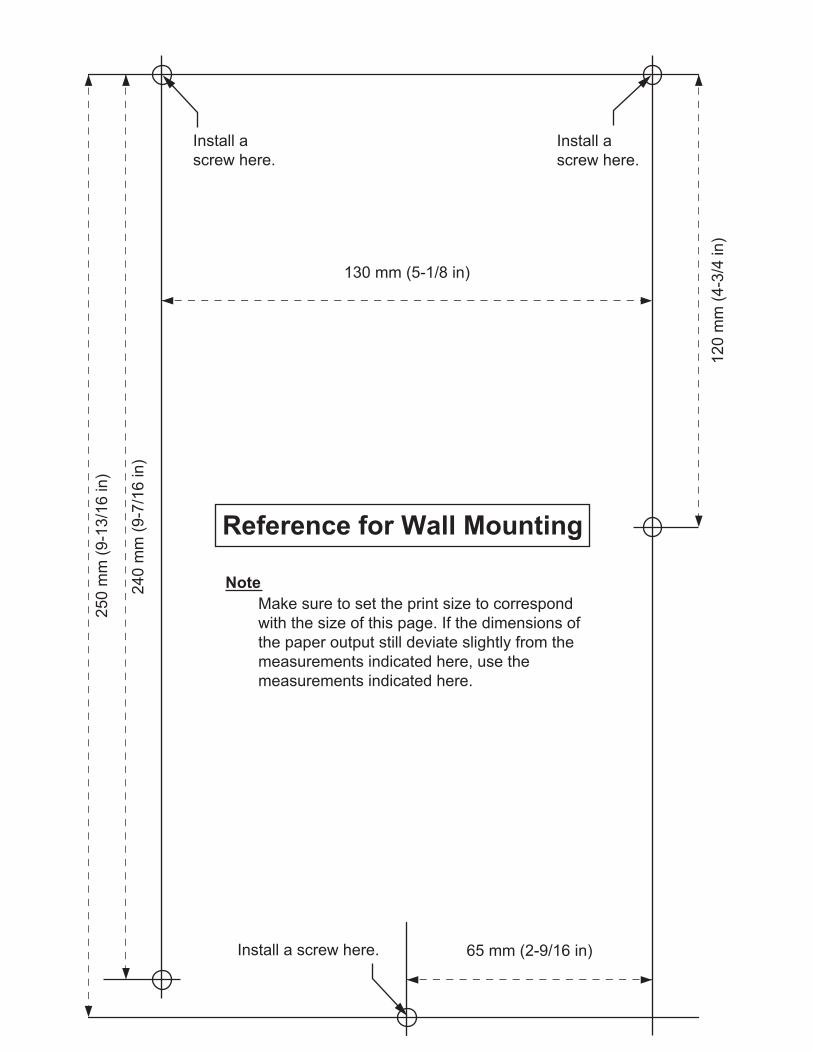
Install a screw here.
Install a
screw here.
Reference for Wall Mounting
25
0 m
m (
9-1
3/1
6 in
)
24
0 m
m (
9-7
/16
in
)
65 mm (2-9/16 in)
130 mm (5-1/8 in)
Install a
screw here.
12
0 m
m (
4-3
/4 in
)
Note
Make sure to set the print size to correspond
with the size of this page. If the dimensions of
the paper output still deviate slightly from the
measurements indicated here, use the
measurements indicated here.

Document Version 2010-11 Installation Manual 143
Notes
One Panasonic Way, Secaucus, New Jersey 07094
http://www.panasonic.com/csd
Copyright:
This material is copyrighted by Panasonic System Networks Co., Ltd., and may be reproduced for internal
use only. All other reproduction, in whole or in part, is prohibited without the written consent of Panasonic
System Networks Co., Ltd.
© Panasonic System Networks Co., Ltd. 2010
PSQX3100RA KK0104EK8110
MODEL NO.
SERIAL NO.
DATE OF PURCHASE
NAME OF DEALER
DEALER'S ADDRESS
DEALER'S TEL. NO.
When you ship the product
Carefully pack and send it prepaid, adequately insured and preferably in the original carton. Attach a
postage-paid letter, detailing the symptom, to the outside of the carton. DO NOT send the product to the
Executive or Regional Sales offices. They are NOT equipped to make repairs.
Product Service
Panasonic Factory Service Centers for this product are listed in the service center directory. Consult your
certified Panasonic dealer for detailed instructions.
For Future Reference
Please print, record, and retain the following information for future reference.
NoteThe serial number of this product can be found on the label affixed to the unit. You should record the model number and the serial number of this unit as a permanent record of your purchase to aid in identification in the event of theft.


![1].pdfModel No. KX-TDA50/KX-TDA100 KX-TDA200/KX-TDA600 Hybrid IP-PBX Operating Manual Thank you for purchasing a Panasonic Hybrid IP-PBX. Please read this manual carefully before using](https://static.fdocuments.in/doc/165x107/5ea72f88c6b46f57ee1a0265/1pdf-model-no-kx-tda50kx-tda100-kx-tda200kx-tda600-hybrid-ip-pbx-operating.jpg)