Hybrid gas sensor platform based on capacitive coupled field effect transistors: Ammonia and...
7
Sensors and Actuators B 127 (2007) 161–167 Hybrid gas sensor platform based on capacitive coupled field effect transistors: Ammonia and nitrogen dioxide detection Alexandru Oprea a,∗ , Heinz-Peter Frerichs b , Christoph Wilbertz b , Mirko Lehmann b , Udo Weimar a a Institute for Physical and Theoretical Chemistry, Auf der Morgenstelle 15, 72076 T¨ ubingen, Germany b Micronas GmbH, Hans-Bunte-Street 19, 79108 Freiburg, Germany Available online 20 August 2007 Abstract A versatile gas sensor platform based on capacitive coupled field effect transistors (CC-FET) was realised and successfully tested. The hybrid sensor structures contain gas sensitive thin organic and inorganic films incorporated in the suspended gates (SG) as sensing elements. The sensors show good functionality and gas sensitivity at room temperature. The dissipated power during operation does not exceed 1MW. © 2007 Elsevier B.V. All rights reserved. Keywords: Gas sensor; Gas hybrid FET; NO 2 ; NH 3 detection 1. Introduction The first gas sensing field effect transistor (gas-FET) [1,2] was a hydrogen sensor having a heated Pd gate as sensing ele- ment. The analyte, which diffuses through the thin metallic layer at its interface with the channel oxide, modifies the work function of the Pd and modulates in this way the channel conductance. The gas-FET was developed afterwards toward more versa- tile hybrid structures. Many of them use suspended gates (SG) coated with gas sensing materials and separated by an air gap from the FET channel [3], as proposed by Janata [4]. In this way, the advantage is that the sensitive SG (SSG) can be produced in independent technological steps, by different technological pro- cedures and on a large variety of substrates. Moreover, the free surface of the SSG is directly “seen” and “felt” across the gap by the transistor channel and no diffusion process through the sensing layer is required by the sensing mechanisms. However, the analyte has still to diffuse through this air gap so that larger air gaps would reduce the response and recovery times of the sensor. In its turn, the increase of the air gap is decreasing the transistor transconductance due to a thicker “effective oxide” and, thus, its gas sensitivity. ∗ Corresponding author. Tel.: +49 70712977633; fax: +49 7071295960. E-mail address: [email protected] (A. Oprea). A good compromise can be realised by using a 1–5 m dis- tance between the SG and the channel. The improvement of the standard SG-FET structure, still the most used in gas sensing applications, is the capacitive (charge) coupled one (SG-CC-FET) [5]. In CC-FETs the poten- tial resulted from the gas interaction with the sensing films deposited on an external SG is transferred to a buried-in gate situated over the channel (see Fig. 1). This design ensures a bet- ter protection of the FET transducer against poisoning analytes to which only the external gate is now exposed. During the last decade, many authors tried to optimise or innovate the gas-FET structures [6–15] and different organic and inorganic materials (metals, metal oxides and organic semiconductors, and even non-conducting polymers), able to produce an electrical potential response when interacting with the target gases, have been deposited on SG and tested as sensing layers [10–19]. The interest for the field effect gas sensing was continuously increasing so that since 2000, more than 60 referred articles and communications have been pub- lished. The challenge in the SG-FET sensor design and produc- tion nowadays is to provide additional facilities besides a good performance [9,11–13]. In order to compensate the limited selec- tivity of the sensing materials, sensor combinations or arrays are often required. Both SG-FET types offer the possibility to develop such complex structures together with signal condi- tioning and a first processing stage (at least) on one chip. The 0925-4005/$ – see front matter © 2007 Elsevier B.V. All rights reserved. doi:10.1016/j.snb.2007.07.030
-
Upload
alexandru-oprea -
Category
Documents
-
view
215 -
download
1
Transcript of Hybrid gas sensor platform based on capacitive coupled field effect transistors: Ammonia and...

A
ss©
K
1
wmaoTtcfticsbstasta
0d
Sensors and Actuators B 127 (2007) 161–167
Hybrid gas sensor platform based on capacitive coupled field effecttransistors: Ammonia and nitrogen dioxide detection
Alexandru Oprea a,∗, Heinz-Peter Frerichs b, Christoph Wilbertz b,Mirko Lehmann b, Udo Weimar a
a Institute for Physical and Theoretical Chemistry, Auf der Morgenstelle 15, 72076 Tubingen, Germanyb Micronas GmbH, Hans-Bunte-Street 19, 79108 Freiburg, Germany
Available online 20 August 2007
bstract
A versatile gas sensor platform based on capacitive coupled field effect transistors (CC-FET) was realised and successfully tested. The hybridensor structures contain gas sensitive thin organic and inorganic films incorporated in the suspended gates (SG) as sensing elements. The sensorshow good functionality and gas sensitivity at room temperature. The dissipated power during operation does not exceed 1 MW.
2007 Elsevier B.V. All rights reserved.
t
t(tdstt
iasptsstl
eywords: Gas sensor; Gas hybrid FET; NO2; NH3 detection
. Introduction
The first gas sensing field effect transistor (gas-FET) [1,2]as a hydrogen sensor having a heated Pd gate as sensing ele-ent. The analyte, which diffuses through the thin metallic layer
t its interface with the channel oxide, modifies the work functionf the Pd and modulates in this way the channel conductance.he gas-FET was developed afterwards toward more versa-
ile hybrid structures. Many of them use suspended gates (SG)oated with gas sensing materials and separated by an air gaprom the FET channel [3], as proposed by Janata [4]. In this way,he advantage is that the sensitive SG (SSG) can be produced inndependent technological steps, by different technological pro-edures and on a large variety of substrates. Moreover, the freeurface of the SSG is directly “seen” and “felt” across the gapy the transistor channel and no diffusion process through theensing layer is required by the sensing mechanisms. However,he analyte has still to diffuse through this air gap so that largerir gaps would reduce the response and recovery times of theensor. In its turn, the increase of the air gap is decreasing the
ransistor transconductance due to a thicker “effective oxide”nd, thus, its gas sensitivity.∗ Corresponding author. Tel.: +49 70712977633; fax: +49 7071295960.E-mail address: [email protected] (A. Oprea).
tptadt
925-4005/$ – see front matter © 2007 Elsevier B.V. All rights reserved.oi:10.1016/j.snb.2007.07.030
A good compromise can be realised by using a 1–5 �m dis-ance between the SG and the channel.
The improvement of the standard SG-FET structure, stillhe most used in gas sensing applications, is the capacitivecharge) coupled one (SG-CC-FET) [5]. In CC-FETs the poten-ial resulted from the gas interaction with the sensing filmseposited on an external SG is transferred to a buried-in gateituated over the channel (see Fig. 1). This design ensures a bet-er protection of the FET transducer against poisoning analyteso which only the external gate is now exposed.
During the last decade, many authors tried to optimise ornnovate the gas-FET structures [6–15] and different organicnd inorganic materials (metals, metal oxides and organicemiconductors, and even non-conducting polymers), able toroduce an electrical potential response when interacting withhe target gases, have been deposited on SG and tested asensing layers [10–19]. The interest for the field effect gasensing was continuously increasing so that since 2000, morehan 60 referred articles and communications have been pub-ished.
The challenge in the SG-FET sensor design and produc-ion nowadays is to provide additional facilities besides a gooderformance [9,11–13]. In order to compensate the limited selec-
ivity of the sensing materials, sensor combinations or arraysre often required. Both SG-FET types offer the possibility toevelop such complex structures together with signal condi-ioning and a first processing stage (at least) on one chip. The
162 A. Oprea et al. / Sensors and Actuators B 127 (2007) 161–167
Cp
2
2
FMcswiictawos
attaind(t
2
etn
dbs
F
∼mf
2
i
•
•
•
Fig. 1. CC-FET structure.
C-FET platform and the sensors we realised with this platform,resented together along the paper, stand for such an attempt.
. Experimental
.1. The transistor platform
The sensor arrays, manufactured by us, are based on a CC-ET platform (see Fig. 2) containing three pairs of p-channelOS-FETs, a measuring one and a reference one. Each pair is
onnected to a differential output stage resulting in three “mea-uring paths”. The application specific integrated circuit (ASIC)as designed and implemented in standard CMOS technology
n order to ensure a large scale and low cost production and easen further improvements. The gas-FET (see Fig. 1) has: 2.4 �mhannel length, 8 �m channel width and needs ∼10 �A to reachhe isothermal operation point. In the test ASIC different materi-ls have been employed for the buried-in gate: AlCu passivatedith silicon nitride, poly-Si and simple AlCu. Optimal air gapsf 1–5 �m were realised by the deposition and etching of someupplementary layers.
The platform includes additional elements and circuits suchs: active heaters; gap thermometer, differential readout stageshat make it very versatile (Fig. 2). The sensitive elements ofhe sensor array, thin organic or inorganic films, are coated onseparated Si wafers (∼1 mm × 2 mm) which are used as SG
n the hybrid transistor structure. Only one electrical contact iseeded to connect the SG to the sensor platform. For tests, theevices were mounted in 40 pin dual in line (DIL) housingsFig. 2); they dissipate in normal operating conditions, at roomemperature, less than 1 MW.
.2. The sensing layers
Two types of sensing layers have been tested: 200 nm thermalvaporated copper phthalocyanine (CuPc) and 200 nm sputtereditanium nitride (TiN). No photo-microlithography processes areeeded to process the sensing layers on gates.
The CuPc films (dedicated to NO2 detection) have been pro-uced by thermal evaporation at a rate of 1.5 nm/min from aoron nitride crucible in high vacuum conditions. The sub-trates were unheated. The pressure during deposition was
or
ig. 2. Sensor layout (up) and its experimental packaging version (down).
10−7 mbar. The TiN films (sensitive to NH3) were realised byagnetron reactive sputtering in low pressure N2 atmosphere
rom a Ti target under standard conditions.
.3. The measuring system and test procedures
Both sensing layers and gas-FET sensors were characterisedn complex measuring systems consisting of:
computer controlled gas mixing stations to produce the testmixtures from high purity carrier gas (synthetic air generator)and high purity analytes from bottles or evaporators.Kelvin Probes Besoke 07 and, respectively, McAllisterKP6500 with online acquisition systems.Driving and acquisition electronics for 12 CC-FET platforms.
The samples, either sensitive layers for KP measurementsr complete CC-FET sensors, have been exposed to NO2 and,espectively, NH3 target gases, dosed as incremental pulses of
A. Oprea et al. / Sensors and Actua
F(
ccbsich
3
3
FpidrvFbl(otritwTtdppops
3
(
isiapsllbCtslcatgtare
frfpoammonia in the case of CuPc (Fig. 7) and from nitrogendioxide in the case of TiN (Fig. 8). In common applicationsit might not be necessary to perform compensation mea-sures.
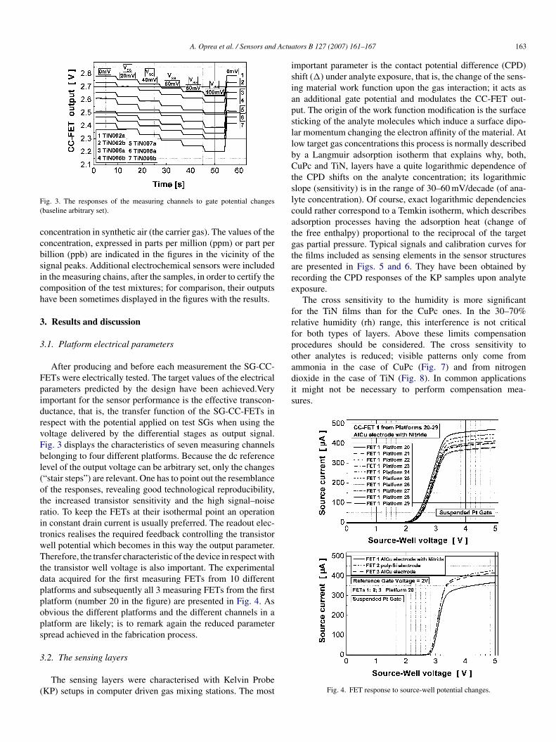
ig. 3. The responses of the measuring channels to gate potential changesbaseline arbitrary set).
oncentration in synthetic air (the carrier gas). The values of theoncentration, expressed in parts per million (ppm) or part perillion (ppb) are indicated in the figures in the vicinity of theignal peaks. Additional electrochemical sensors were includedn the measuring chains, after the samples, in order to certify theomposition of the test mixtures; for comparison, their outputsave been sometimes displayed in the figures with the results.
. Results and discussion
.1. Platform electrical parameters
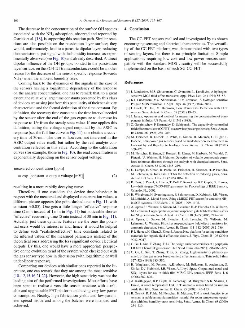
After producing and before each measurement the SG-CC-ETs were electrically tested. The target values of the electricalarameters predicted by the design have been achieved.Verymportant for the sensor performance is the effective transcon-uctance, that is, the transfer function of the SG-CC-FETs inespect with the potential applied on test SGs when using theoltage delivered by the differential stages as output signal.ig. 3 displays the characteristics of seven measuring channelselonging to four different platforms. Because the dc referenceevel of the output voltage can be arbitrary set, only the changes“stair steps”) are relevant. One has to point out the resemblancef the responses, revealing good technological reproducibility,he increased transistor sensitivity and the high signal–noiseatio. To keep the FETs at their isothermal point an operationn constant drain current is usually preferred. The readout elec-ronics realises the required feedback controlling the transistorell potential which becomes in this way the output parameter.herefore, the transfer characteristic of the device in respect with
he transistor well voltage is also important. The experimentalata acquired for the first measuring FETs from 10 differentlatforms and subsequently all 3 measuring FETs from the firstlatform (number 20 in the figure) are presented in Fig. 4. Asbvious the different platforms and the different channels in alatform are likely; is to remark again the reduced parameterpread achieved in the fabrication process.
.2. The sensing layers
The sensing layers were characterised with Kelvin ProbeKP) setups in computer driven gas mixing stations. The most
tors B 127 (2007) 161–167 163
mportant parameter is the contact potential difference (CPD)hift (�) under analyte exposure, that is, the change of the sens-ng material work function upon the gas interaction; it acts asn additional gate potential and modulates the CC-FET out-ut. The origin of the work function modification is the surfaceticking of the analyte molecules which induce a surface dipo-ar momentum changing the electron affinity of the material. Atow target gas concentrations this process is normally describedy a Langmuir adsorption isotherm that explains why, both,uPc and TiN, layers have a quite logarithmic dependence of
he CPD shifts on the analyte concentration; its logarithmiclope (sensitivity) is in the range of 30–60 mV/decade (of ana-yte concentration). Of course, exact logarithmic dependenciesould rather correspond to a Temkin isotherm, which describesdsorption processes having the adsorption heat (change ofhe free enthalpy) proportional to the reciprocal of the targetas partial pressure. Typical signals and calibration curves forhe films included as sensing elements in the sensor structuresre presented in Figs. 5 and 6. They have been obtained byecording the CPD responses of the KP samples upon analytexposure.
The cross sensitivity to the humidity is more significantor the TiN films than for the CuPc ones. In the 30–70%elative humidity (rh) range, this interference is not criticalor both types of layers. Above these limits compensationrocedures should be considered. The cross sensitivity tother analytes is reduced; visible patterns only come from
Fig. 4. FET response to source-well potential changes.

164 A. Oprea et al. / Sensors and Actuators B 127 (2007) 161–167
Fig. 5. Typical KP signal (up) and calibrations curves (down) for CuPc sensingfilms. The values of the NO2 concentration during the exposure periods were inorder: 100 ppb, 300 ppb, 1 ppm, 3 ppm; rh denotes the relative humidity.
Fig. 6. Typical KP signal (up) and calibrations curves (down) for TiN sensingfilms. The values of the NH3 concentration during the exposure periods were inorder: 0.5, 1, 3, 10 and 30 ppm; rh denotes the relative humidity.
3
ibc
c
aFiopc
rtor
ttfvc
Fig. 7. CuPc cross sensitivity to NH3.
.3. The CC-FET gas sensors
The gas sensitive SG-CC-FETs including both types of sens-ng layers show high sensitivity to the target gases. They haveeen operated many months with good results, but statisticalonclusions are still premature.
Figs. 9 and 10 are illustrating the responses and the calibrationurves of the CuPc and TiN-FET sensors.
One has again to point out the reduced parameter spreadmong the sensors from the same platform (indices a and b inigs. 9 and 10) or from different platforms (different numerical
ndices in Figs. 9 and 10) as well as the reduced drift duringperation. This was assured by an appropriate design of thelatform structure, previewed with guard rings against surfaceharge migration and adequate passivation layers.
Another remarkable feature of our CC-FET sensors is theeduced cross sensitivity to other gases, as already observed inhe case of the sensing layers. For the ammonia gas-FETs basedn TiN films the comparative experimental data for 0 and 40%h are included in Fig. 10.
As obvious from Figs. 6 and 10, the humidity influence onhe TiN-SG-CC-FET response is opposite to the one encoun-
ered at the independent films, when tested as KP samples. Thisact is probably due to some residual interaction of the waterapours with the passivation layers deposited on the top of thehip (transistor) and will be addressed below.Fig. 8. TiN cross sensitivity to NOx and ethanol.

A. Oprea et al. / Sensors and Actuators B 127 (2007) 161–167 165
Fig. 9. FETs response to NO2 at 25 ◦C at a rate of 40% relative humidity (up)and their calibration curves (down).
Fig. 10. TiN-FET response to NH3 at 25 ◦C at a rate of 0 and 40% relativehumidity (up) and their calibration curves (down).
Fig. 11. TiN-FET response and time constants at 25 ◦C and 40% relative humid-ity and the inferred “effective” time constants (see the comments in the text).The indices of the time constant τV,C;ON,OFF address as follows: V: the voltagesignal of the CC-FET sensor; C: the concentration value calculated from thevtp
bwFicai
assadpsosImdoibf
adhh(aoirr
oltage signal; ON: the leading edge of the signal expressing the gas adsorp-ion; OFF: the falling edge (decay) of the signal expressing the desorptionrocess.
Owing to the sensor design the humidity interference cane eliminated with the platform reference channels or evenith humidity measuring channels if high accuracy is needed.or simple applications, the standard chip configuration is sat-
sfying. Further improvement of the transistor could be alsoonsidered, for example, by choosing passivation materialsdapted to the target gases. This will reduce, however, thencreased platform versatility.
The “electronic” time constants of the measuring CC-FET,s obviously resulting from the transistor characteristics pre-ented in Fig. 3 (see the accuracy of output “voltage stairs”), aremall. The significantly larger values of experimental responsend recovery times of the whole sensor (see Fig. 11) are mainlyue to the sensing films. There is a principle conflictual interde-endence between the sensitivity of the device and its responsepeed. High target gas sensitivity requires strong interactionsf the sensing layer with the analyte that additionally results inlower desorption processes and, hence, in longer recovery time.t is exactly the case of CuPc, which tightly bonds the NO2olecule to its Cu central atom [20], leading to very low gas
etection limits but, also, to increased recovery times. Becausef this disadvantage, the CuPc layers are well suited for alarm-ng purposes, where extremely rare NO2 exposure events are toe expected. Complementary consideration on this topic can beound in [11].
A similar situation is encountered at the TiN films, which areble to strongly interact with the free electron pairs of the NH3ipolar molecules (most likely at the Ti sites) that induce, both,igh sensitivities and relatively large recovery times. Recalling,owever, the increase of the TiN sensitivity with the humiditywhen the material is used for KP samples) one has to considern additional interaction mechanism involving water moleculesr OH groups. The most probable would be the ammonia chem-cal reaction with the routed OH followed by the binding of the
esulting NH4 radicals to the TiN surface intermediated by theemaining O atoms [18].NH3|gas + OH|TiN surface ⇒ O–NH4|TiN surface (1)
1 Actua
aOtwtidlrN
toeocdbrdreAcce
r
rdct“Attttottu
e[lbacea
4
eioapi
R
[
[
[
[
[
[
[
[
66 A. Oprea et al. / Sensors and
The decrease in the concentration of the surface OH speciesssociated with the NH3 adsorption, observed and reported bystrick et al. [18], is supporting this reaction path. Similar reac-
ions are also possible on the passivation layer surface; theyould, unfortunately, lead to a parasitic dipolar layer, reducing
he transistor output signal with the humidity increase, as exper-mentally observed (see Fig. 10) and already described. A directipolar influence of the OH groups, bonded to the passivationayer surface, on the SG-FET transconductance could be anothereason for the decrease of the sensor specific response (towardsH3) when the ambient humidity rises.Coming back to the dynamics of the signals in the case of
he sensors having a logarithmic dependency of the responsen the analyte concentration, one has to remark that, to a greatxtent, the relatively large time constants presented by this classf devices are arising just from this peculiarity of their sensitivityharacteristic and the formal definition of the time constant. Byefinition, the recovery time constant is the time interval neededy the sensor after the end of the gas exposure to decrease itsesponse to 1/e from the steady state value. If one applies thisefinition, taking the voltage signal outputted by the ASIC asesponse (see the full line curve in Fig. 11), one obtains a recov-ry time of 30 min. The user is, however, not interested in theSIC output value itself, but rather by the real analyte con-
entration reflected in this value. According to the calibrationurves (for example, those in Fig. 10), the read concentration isxponentially depending on the sensor output voltage:
measured concentration [ppm]
= exp[constant × output voltage [mV]
](2)
esulting in a more rapidly decaying curve.Therefore, if one considers the device time-behaviour in
espect with the measured and displayed concentration values, aifferent picture appears (the point-dashed one in Fig. 11, withonstant ≈0.05). One gets a little longer “effective” responseime (2 min instead of 1 min in Fig. 11) but noticeable shortereffective” recovering time (5 min instead of 30 min in Fig. 11).ctually, just these dynamic features are the ones the poten-
ial users would be interest in and, hence, it would be helpfulo define such “realistic/effective” time constants related tohe inferred values of the measured parameters instead of theheoretical ones addressing the less significant device electricalutputs. By this, one would have a more appropriate perspec-ive on the evolution trend of the system when checked out withhe gas sensor type now in discussion (with logarithmic or wellnder-linear response).
Comparing our devices with similar ones reported in the lit-rature, one can remark that they are among the most sensitive10–12,15,16,21,22]. However, the high sensitivity was not theeading aim of the performed investigations. Most efforts haveeen spent to realise a versatile sensor structure with a reli-
ble and upgradeable FET platform and having very low poweronsumption. Nearby, high fabrication yields and low param-ter spread inside and among the batches were intended andchieved.[
tors B 127 (2007) 161–167
. Conclusion
The CC-FET sensors realised and investigated by us shownncouraging sensing and electrical characteristics. The versatil-ty of the CC-FET platform was demonstrated with two typesf sensing layers, but there is no principle limitation. Simplepplications, requiring low cost and low power sensors com-atible with the standard MOS circuitry will be successfullymplemented on the basis of such SG-CC-FET.
eferences
[1] I. Lundstrom, M.S. Shivaraman, C. Svensson, L. Lundkvist, A hydrogen-sensitive MOS field-effect transistor, Appl. Phys. Lett. 26 (1974) 55–57.
[2] K.I. Lundstrom, M.S. Shivaraman, C.M. Svenson, A hydrogen-sensitivePd-gate MOS transistor, J. Appl. Phys. 46 (1975) 3876–3881.
[3] I. Eisele, T. Doll, M. Burgmair, Low Power Gas Detection with FET.sensors, Sens. Actuat. B: Chem. 78 (2001) 19–25.
[4] J. Janata, Apparatus and method for measuring the concentration of com-ponents in fluids, US Patent 4,411,741 (1983).
[5] Z. Gergintschew, P. Kornetzky, D. Schipanski, The capacitively controlledfield effect transistor (CCFET) as a new low power gas sensor, Sens. Actuat.B: Chem. 36 (1996) 285–289.
[6] M. Fleischer, B. Ostrick, R. Pohle, E. Simon, H. Meixner, C. Bilger, F.Daeche, Low-power gas sensors based on work-function measurement inlow-cost hybrid flip-chip technology, Sens. Actuat. B: Chem. 80 (2001)169–173.
[7] M. Fleischer, E. Simon, E. Rumpel, H. Ulmer, M. Harbeck, M. Wandel, C.Fietzek, U. Weimer, H. Meixner, Detection of volatile compounds corre-lated to human diseases through the analysis with chemical sensors, Sens.Actuat. B: Chem. 83 (2002) 245–249.
[8] U. Lampe, E. Simon, R. Pohle, M. Fleischer, H. Meixner, H.-P. Frerichs,M. Lehmann, G. Kiss, GasFET for the detection of reducing gases, Sens.Actuat. B: Chem. 111–112 (2005) 106–110.
[9] R. Paris, S. Pawel, R. Herzer, T. Doll, P. Kornetzky, R.P. Gupta, G. Eranna,Low drift air-gap CMOS-FET gas sensor, in: Proceedings of IEEE Sensors,Orlando, FL, 2002.
10] H. Wingbrant, H. Svenningstorp, P. Salomonson, D. Kubinski, J.H. Visser,M. Lofdahl, A. Lloyd-Spetz, Using a MISiC-FET sensor for detecting NH3
in SCR systems, IEEE Sens. J. 5 (2005) 1099–1105.11] A. Oprea, U. Weimar, E. Simon, M. Fleischer, H.-P. Frerichs, Ch. Wilbertz,
M. Lehmann, Copper phthalocyanine suspended gate field effect transistorsfor NO2 detection, Sens. Actuat. B: Chem. 118 (1–2) (2006) 249–254.
12] A. Oprea, E. Simon, M. Fleischer, H.-P. Frerichs, Ch. Wilbertz, M.Lehmann, U. Weimar, Flip-chip suspended gate field effect transistors forammonia detection, Sens. Actuat. B: Chem. 111–112 (2005) 582–586.
13] F. L’Hereec, H. Chen, Z. Zhou, J. Janata, New platform for testing candidatematerials for organic field-effect transistors, J. Phys. Chem. B 108 (2004)9042–9047.
14] C. Gu, L. Sun, T. Zhang, T. Li, The design and characteristics of a porphyrinLB film ChemFET gas sensor, Thin Solid Films 284–285 (1996) 863–865.
15] C. Gu, L. Sun, T. Zhang, T. Li, X. Zhang, High-sensitivity phthalocya-nine LB film gas sensor based on field effect transistors, Thin Solid Films327–329 (1998) 383–386.
16] H. Wingbrant, M. Persson, A.E. Abom, M. Eriksson, B. Andersson, S.Simko, D.J. Kubinski, J.H. Visser, A. Lloyd-Spetz, Cosputtered metal andSiO2 layers for use in thick-film MISiC NH3 sensors, IEEE Sens. J. 6(2006) 887–896.
17] A. Karthigeyan, R.P. Gupta, K. Scharnagl, M. Burgmair, S.K. Sharma, I.Eisele, A room temperature HSGFET ammonia sensor based on iridium
oxide thin film, Sens. Actuat. B: Chem. 85 (2002) 145–153.18] B. Ostrick, R. Pohle, M. Fleischer, H. Meixner, TiN in work function typesensors: a stable ammonia sensitive material for room temperature opera-tion with low humidity cross sensitivity, Sens. Actuat. B: Chem. 68 (2000)234–239.
Actua
[
[
[
[
B
AiBrtAGUh
HhooGs
Cw1tbGs
MPG
U1tinterest focuses on chemical sensors as well as on multicomponent analysis and
A. Oprea et al. / Sensors and
19] A. Salomonsson, S. Roy, C. Aulin, L. Ojamae, P.-O. Kall, M. Strand, M.Sanati, A. Lloyd Spetz, RuO2 and Ru nanoparticles for MISiC-FET gas sen-sors, in: 2005 NSTI Nanotechnology Conference and Trade Show—NSTINanotech 2005 Technical Proceedings, Anaheim, CA, 2005.
20] J. Claußen, Ch. Fietzek, M. Harbeck, U. Weimar, H.-G. Mack, Electronicstructures of phthalocyanines after exposure to NO2, in: 6th DresdnerSensor Symposium, Dresden, Germany, 2003.
21] A.E. Abom, L. Hultmann, M. Eriksson, R.D. Twesten, Properties of com-bined TiN and Pt thin films applied to gas sensing, J. Vac. Sci. Technol., A20 (2002) 667–673.
22] E.J. Connolly, B. Timmer, H.T.M. Pham, J. Groeneweg, P.M. Sarro, W.Olthuis, P.J. French, A new ammonia sensor based on a porous SiC mem-brane, Sens. Actuat. B: Chem. 109 (2005) 44–46.
iographies
lexandru Oprea received diploma in physics from the University of Bucharestn 1976 and Ph.D. in solid-state physics from the Central Institute of Physics,ucharest, Romania in 1996. He got successively the positions of scientific
esearcher, senior researcher and principal senior researcher at the National Insti-
ute for Materials Physics, Bucharest. He joined, for 3 years (1997–2000), thepplied Physics—Sensors Department of the Technical University of Cottbus,ermany, and since 2002, is senior scientist in the Gas Sensor Group of theniversity of Tuebingen, Germany. The research fields: thin films solar cells,igh field electroluminescent devices, polymer and metal oxide gas sensors.pnNd
tors B 127 (2007) 161–167 167
einz-Peter Frerichs studied physics at the University of Heidelberg wheree received his diploma in 1980 and Ph.D. in 1982. From 1984, he workedn technology development of the semiconductor industry in Germany, mostlyn nonvolatile memory development. Since 1994, he is working at MicronasmbH in Freiburg, Germany on the development of nonvolatile memories and
ensors.
hristoph Wilbertz studied physics at the University of Heidelberghere he received his diploma in 1988 and his Ph.D. in 1991. From995, he worked on technology development of the semiconductor indus-ry in France and Germany, on memory, CMOS and high frequencyipolar device development. Since 2003, he is working at MicronasmbH in Freiburg, Germany on the development of FET based gas
ensors.
irko Lehmann studied physics at the University of Freiburg, and received hish.D. from the University of Rostock. Since 1995, he is working at MicronasmbH, currently as group leader in the field of bio and gas sensors.
doWeimar received his diploma in physics in 1989, Ph.D. in chemistry in993 and habilitation in 2002 from the University of Tuebingen. He is currentlyhe head of Gas Sensors Group at the University of Tuebingen. His research
attern recognition. He is the author of about 180 scientific papers and shortotes. He is responsible for several European projects and for co-ordinating theetworks of Excellence NOSE and GOSPEL (see also http://ipc.uni-tuebingen.e/weimar/).