Hybrid Gas Atomization for Powder Production
28
5 Hybrid Gas Atomization for Powder Production Udo Fritsching and Volker Uhlenwinkel University of Bremen Germany 1. Introduction Atomization of a molten liquid melt is a versatile method for powder production. Main operational parameters and physical conditions for a suitable atomization process for different applications in powder production are: - melt type: surface tension, viscosity and temperature range (solidification temperature), - process type: aimed throughput, energy efficiency, - product type: particle size distribution (mean particle size and width of distribution). Most atomization processes e.g. for metal powder production are gas atomization processes using twin fluid atomizers. For these applications, besides the use of standard atomizer types, relevant developments are ongoing to derive advanced atomizer concepts for improved powder products and energy and resources effective atomization processes. Main aims of atomizer developments are: - minimization of (mean) particle sizes, - narrowing of the particle size distribution width, - effective use of resources (gas and feed stock), - technical production of complex melt systems for powder applications. In this contribution the development of gas atomization units is described, which utilize characteristic flow effects of a molten metal stream in relation to the flow of compressed gases for efficient fragmentation of liquids and melts. The interaction of gas and liquid melt in the twin-fluid atomization process is used for understanding and optimization of melt fragmentation processes. 2. Atomization of liquids and melts Atomization of liquids (e.g., pure liquids, solutions, suspensions and emulsions, or melts) is a classic process engineering unit operation. The process of liquid atomization has applications in numerous industrial branches, for example, in chemical, mechanical, aerospace, and civil engineering as well as in material science and technology and metallurgy, food processing, pharmaceuticals, agriculture and forestry, environmental protection, medicine, and others. Within atomization, the bulk fluid (continuous liquid phase) is transformed into a spray system (dispersed phase: droplets). The disintegration process itself is caused either by www.intechopen.com
Transcript of Hybrid Gas Atomization for Powder Production

5
Hybrid Gas Atomization for Powder Production
Udo Fritsching and Volker Uhlenwinkel University of Bremen
Germany
1. Introduction
Atomization of a molten liquid melt is a versatile method for powder production. Main operational parameters and physical conditions for a suitable atomization process for different applications in powder production are:
- melt type: surface tension, viscosity and temperature range (solidification temperature), - process type: aimed throughput, energy efficiency, - product type: particle size distribution (mean particle size and width of distribution).
Most atomization processes e.g. for metal powder production are gas atomization processes using twin fluid atomizers. For these applications, besides the use of standard atomizer types, relevant developments are ongoing to derive advanced atomizer concepts for improved powder products and energy and resources effective atomization processes.
Main aims of atomizer developments are:
- minimization of (mean) particle sizes, - narrowing of the particle size distribution width, - effective use of resources (gas and feed stock), - technical production of complex melt systems for powder applications.
In this contribution the development of gas atomization units is described, which utilize characteristic flow effects of a molten metal stream in relation to the flow of compressed gases for efficient fragmentation of liquids and melts. The interaction of gas and liquid melt in the twin-fluid atomization process is used for understanding and optimization of melt fragmentation processes.
2. Atomization of liquids and melts
Atomization of liquids (e.g., pure liquids, solutions, suspensions and emulsions, or melts) is a classic process engineering unit operation. The process of liquid atomization has applications in numerous industrial branches, for example, in chemical, mechanical, aerospace, and civil engineering as well as in material science and technology and metallurgy, food processing, pharmaceuticals, agriculture and forestry, environmental protection, medicine, and others.
Within atomization, the bulk fluid (continuous liquid phase) is transformed into a spray system (dispersed phase: droplets). The disintegration process itself is caused either by
www.intechopen.com

Powder Metallurgy
100
intrinsic (e.g., potential) or extrinsic (e.g., kinetic) energy, where the liquid, which is typically fed into the process in the form of a liquid jet or sheet, is atomized either due to the kinetic energy contained in the liquid itself, by the interaction of the liquid sheet or jet with a (high-velocity) gas, or by means of mechanical energy delivered externally, e.g., by rotating devices.
The main purpose of technical atomization processes is the generation of a significantly increased gas–liquid interface in the dispersed multiphase system. All transfer processes across the gas–liquid phase boundary directly depend on the driving potential difference of the exchange property (heat, mass, or momentum) and the size of the exchange surface. This gas–liquid contact area in a dispersed spray system is correlated with the integral sum of the surfaces of all individual droplets within the spray. An increase in the relative interphase area in a dispersed system intensifies momentum, heat, and mass-transfer processes between the gas and liquid. The total flux of exchange within spray systems is thereby increased by several orders of magnitude.
Within the atomization process typically a liquid stream (jet or sheet) is disintegrated into a large number of droplets of various sizes. As all of the solid state materials as minerals, ceramics, glass and metals may be converted into the liquid state by melting, powders from all of these materials may be produced via atomization of the liquid melt and consecutive solidification of the droplets in the spray to achieve a powder.
The area of melt atomization differs in several ways and properties from a conventional atomization process (lets say from water or fuel atomization) due to the physical melt conditions as:
- high temperatures above the relevant melting point - comparably high surface tensions (metal melts) - comparably high viscosity (glass or ceramic melts)
The general physics, devices and application of (conventional) atomization and spray processes have been reviewed and intensively published as e.g. in (Lefebvre, 1989; Bayvel & Orzechowski, 1993; Fritsching; 2006; Ashgriz, 2011).
2.1 Gas atomization of liquid melts
Several principle atomisation mechanisms and devices exist for disintegration of molten metals. An overview on molten metal atomisation techniques and devices is given e.g. by (Lawley, 1992; Bauckhage, 1992; Yule & Dunkley, 1994, and Nasr et al., 2002). In the area of metal powder production by atomisation of molten metals typically twin-fluid atomisation by means of inert gases is used. Main reasons for using this specific atomisation technique are:
- the possibility of high throughputs and disintegration of high mass flow rates - the greater amount of heat transfer between gas and particles for rapid partially cooling
the particles - the direct delivery of kinetic energy to accelerate the particles towards the
substrate/deposit for compaction - the minimization of oxidation risks of the atomised materials within the spray process
by use of inert gases.
www.intechopen.com
Hybrid Gas Atomization for Powder Production
101
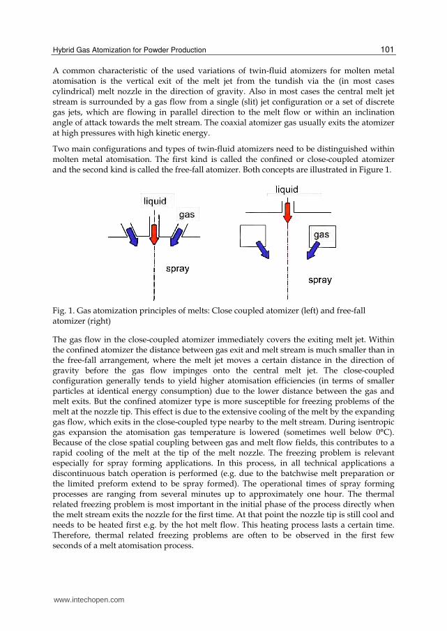
A common characteristic of the used variations of twin-fluid atomizers for molten metal atomisation is the vertical exit of the melt jet from the tundish via the (in most cases cylindrical) melt nozzle in the direction of gravity. Also in most cases the central melt jet stream is surrounded by a gas flow from a single (slit) jet configuration or a set of discrete gas jets, which are flowing in parallel direction to the melt flow or within an inclination angle of attack towards the melt stream. The coaxial atomizer gas usually exits the atomizer at high pressures with high kinetic energy.
Two main configurations and types of twin-fluid atomizers need to be distinguished within molten metal atomisation. The first kind is called the confined or close-coupled atomizer and the second kind is called the free-fall atomizer. Both concepts are illustrated in Figure 1.
Fig. 1. Gas atomization principles of melts: Close coupled atomizer (left) and free-fall atomizer (right)
The gas flow in the close-coupled atomizer immediately covers the exiting melt jet. Within the confined atomizer the distance between gas exit and melt stream is much smaller than in the free-fall arrangement, where the melt jet moves a certain distance in the direction of gravity before the gas flow impinges onto the central melt jet. The close-coupled configuration generally tends to yield higher atomisation efficiencies (in terms of smaller particles at identical energy consumption) due to the lower distance between the gas and melt exits. But the confined atomizer type is more susceptible for freezing problems of the melt at the nozzle tip. This effect is due to the extensive cooling of the melt by the expanding gas flow, which exits in the close-coupled type nearby to the melt stream. During isentropic gas expansion the atomisation gas temperature is lowered (sometimes well below 0°C). Because of the close spatial coupling between gas and melt flow fields, this contributes to a rapid cooling of the melt at the tip of the melt nozzle. The freezing problem is relevant especially for spray forming applications. In this process, in all technical applications a discontinuous batch operation is performed (e.g. due to the batchwise melt preparation or the limited preform extend to be spray formed). The operational times of spray forming processes are ranging from several minutes up to approximately one hour. The thermal related freezing problem is most important in the initial phase of the process directly when the melt stream exits the nozzle for the first time. At that point the nozzle tip is still cool and needs to be heated first e.g. by the hot melt flow. This heating process lasts a certain time. Therefore, thermal related freezing problems are often to be observed in the first few seconds of a melt atomisation process.
www.intechopen.com
Powder Metallurgy
102
In addition to the thermal related freezing problem within the melt nozzle, also chemical or metallurgical related problems in melt delivery systems are found frequently. Not all of these problems are solved yet in melt atomisation applications. A range of problems arises from the possible change of material composition of the melt, or that of the tundish or nozzle material, due to possible melt/tundish reactions or melt segregational effects from diffusion. This reaction process kinetics is somewhat slower than the thermal freezing process kinetics mentioned before and may contribute to operational problems at a later temporal state of process operation.
Free-fall atomizers are much less problematic than close-coupled atomizers in terms of thermal freezing processes, as the melt jet stream and the gas stream are well separated at the exit of the melt from the delivery system (tundish exit). Therefore, the cooling of the melt due to the cold gas occurs at a later position than within close-coupled atomizers. The free-fall atomizer obeys as an additional advantage in the frame of spray forming the possibility of controlled mechanical or pneumatic scanning and therefore oscillating the gas atomizer with respect to one axis. Also concepts of spatial/temporal distribution of segments of gas jets within the nozzle can be used for atomisation. By doing so, the free-fall atomizer gives the operator an additional degree of freedom with respect to the control and regulation of the mass flux distribution of droplets in the spray. This most important physical property of the spray within other atomizer nozzle systems can (within a running process) only be influenced by changing the atomizer gas pressure. By controlled scanning of the nozzle, the mass flux can also be distributed over a certain area (necessary e.g. for flat product spray forming).
3. Free-fall atomizer design for melts
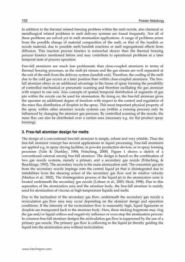
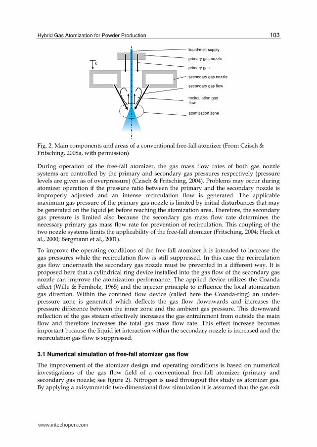
The design of a conventional free-fall atomizer is simple, robust and very reliable. Thus the free-fall atomizer concept has several applications in liquid processing. Free-fall atomizers are applied e.g. in spray drying facilities, in powder production devices, or in spray forming processes (Yule & Dunkley, 1994; Fritsching, 2008). Figure 1 shows a sketch of a conventional external mixing free-fall atomizer. The design is based on the combination of two gas nozzle systems, namely a primary and a secondary gas nozzle (Fritsching, & Bauckhage, 1992). The secondary nozzle is the main atomization unit. The concentric gas jets from the secondary nozzle impinge onto the central liquid jet that is disintegrated due to instabilities from the shearing action of the secondary gas flow and its relative velocity (Markus et al., 2002). The disintegration process of the liquid jet in the atomization zone is located underneath the secondary gas nozzle (Lohner et al., 2003; Heck, 1998). Due to this separation of the atomization area and the atomizer body, the free-fall atomizer is mainly used for atomization of viscous or high temperature liquids and melts.
Due to the inclination of the secondary gas flow, underneath the secondary gas nozzle a recirculation gas flow area may occur depending on the atomizer design and operation conditions. If the intensity of the recirculation flow is reasonably high, liquid ligaments or droplets are transported back to the atomizer body. Here, these sticking fragments may clog the gas and/or liquid orifices and negatively influence or even stop the atomization process. In common free-fall atomizer designs the recirculation gas flow is suppressed by the use of a primary gas nozzle. The primary gas flow is coflowing to the liquid jet thereby guiding the liquid into the atomization area without recirculation.
www.intechopen.com
Hybrid Gas Atomization for Powder Production
103
primary gas nozzle
secondary gas nozzle
secondary gas flow
primary gas
liquid/melt supply
recirculation gas flow
atomization zone
x
Fig. 2. Main components and areas of a conventional free-fall atomizer (From Czisch & Fritsching, 2008a, with permission)
During operation of the free-fall atomizer, the gas mass flow rates of both gas nozzle systems are controlled by the primary and secondary gas pressures respectively (pressure levels are given as of overpressure) (Czisch & Fritsching, 2004). Problems may occur during atomizer operation if the pressure ratio between the primary and the secondary nozzle is improperly adjusted and an intense recirculation flow is generated. The applicable maximum gas pressure of the primary gas nozzle is limited by initial disturbances that may be generated on the liquid jet before reaching the atomization area. Therefore, the secondary gas pressure is limited also because the secondary gas mass flow rate determines the necessary primary gas mass flow rate for prevention of recirculation. This coupling of the two nozzle systems limits the applicability of the free-fall atomizer (Fritsching, 2004; Heck et al., 2000; Bergmann et al., 2001).
To improve the operating conditions of the free-fall atomizer it is intended to increase the gas pressures while the recirculation flow is still suppressed. In this case the recirculation gas flow underneath the secondary gas nozzle must be prevented in a different way. It is proposed here that a cylindrical ring device installed into the gas flow of the secondary gas nozzle can improve the atomization performance. The applied device utilizes the Coanda effect (Wille & Fernholz, 1965) and the injector principle to influence the local atomization gas direction. Within the confined flow device (called here the Coanda-ring) an under-pressure zone is generated which deflects the gas flow downwards and increases the pressure difference between the inner zone and the ambient gas pressure. This downward reflection of the gas stream effectively increases the gas entrainment from outside the main flow and therefore increases the total gas mass flow rate. This effect increase becomes important because the liquid jet interaction within the secondary nozzle is increased and the recirculation gas flow is suppressed.
3.1 Numerical simulation of free-fall atomizer gas flow
The improvement of the atomizer design and operating conditions is based on numerical investigations of the gas flow field of a conventional free-fall atomizer (primary and secondary gas nozzle; see figure 2). Nitrogen is used througout this study as atomizer gas. By applying a axisymmetric two-dimensional flow simulation it is assumed that the gas exit
www.intechopen.com
Powder Metallurgy
104
configuration is that of a circular slit nozzle (Lohner, 2002; Lohner et al., 2005). Compressibility (assuming ideal gas flow) as well as turbulence effects (using the conventional k-eps turbulence model) are taken into account. The gas condition at the nozzle exit is assumed as perfectly expanded (supersonic). Pressure levels are given as overpressure (pressure level exceeding the ambient pressure). The orifice areas of primary and secondary gas are kept constant. Therefore, the gas mass flow rates of the primary and the secondary gas nozzle are varied by changing the stagnation gas pressures for primary and secondary gas, respectively.
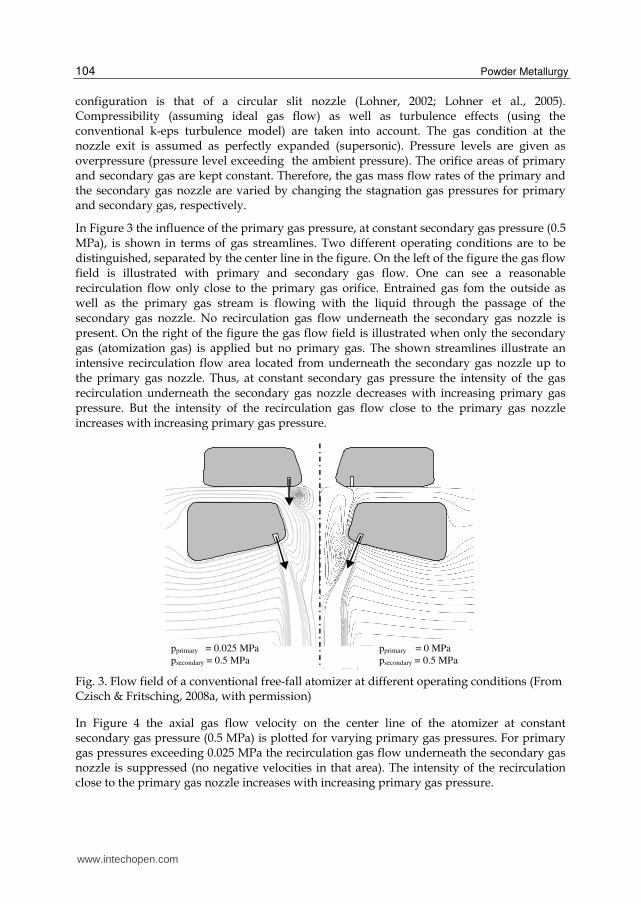
In Figure 3 the influence of the primary gas pressure, at constant secondary gas pressure (0.5 MPa), is shown in terms of gas streamlines. Two different operating conditions are to be distinguished, separated by the center line in the figure. On the left of the figure the gas flow field is illustrated with primary and secondary gas flow. One can see a reasonable recirculation flow only close to the primary gas orifice. Entrained gas fom the outside as well as the primary gas stream is flowing with the liquid through the passage of the secondary gas nozzle. No recirculation gas flow underneath the secondary gas nozzle is present. On the right of the figure the gas flow field is illustrated when only the secondary gas (atomization gas) is applied but no primary gas. The shown streamlines illustrate an intensive recirculation flow area located from underneath the secondary gas nozzle up to the primary gas nozzle. Thus, at constant secondary gas pressure the intensity of the gas recirculation underneath the secondary gas nozzle decreases with increasing primary gas pressure. But the intensity of the recirculation gas flow close to the primary gas nozzle increases with increasing primary gas pressure.
pprimary = 0.025 MPa
psecondary = 0.5 MPa pprimary = 0 MPa
psecondary = 0.5 MPa
Fig. 3. Flow field of a conventional free-fall atomizer at different operating conditions (From Czisch & Fritsching, 2008a, with permission)
In Figure 4 the axial gas flow velocity on the center line of the atomizer at constant secondary gas pressure (0.5 MPa) is plotted for varying primary gas pressures. For primary gas pressures exceeding 0.025 MPa the recirculation gas flow underneath the secondary gas nozzle is suppressed (no negative velocities in that area). The intensity of the recirculation close to the primary gas nozzle increases with increasing primary gas pressure.
www.intechopen.com

Hybrid Gas Atomization for Powder Production
105
-400
-300
-200
-100
0
100
200
300
400
0 50 100 150 200
distance x [mm] .
axia
l gas
vel
oci
ty [
m/s
] .
0.000 MPa
0.009 Mpa
0.025 MPa
0.100 MPa
primary gas influence
secondary gas influence
Fig. 4. Axial gas velocity on the center line at varying primary gas pressures (secondary gas pressure 0.5 MPa) (From Czisch & Fritsching, 2008a, with permission)
In Figure 5 the flow field of the free-fall atomizer without primary gas application is illustrated as streamline distribution (left) and local static pressure distribution (right) at a secondary pressure of 0.5 MPa. A recirculation flow field generated underneath the secondary gas nozzle is visible. The area with highest pressure is located where the atomization gas streams impinge onto the center line. The local static pressure exceeds 50 kPa in this area.
Fig. 5. Flow field (left) and pressure distribution (right) of a conventional free-fall atomizer generated only by the secondary gas flow (scale indicates pressure level in Pa) (From Czisch & Fritsching, 2008a, with permission)
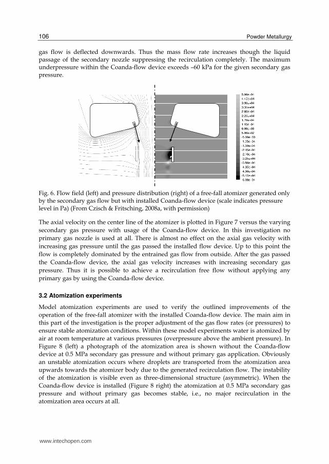
Figure 6 shows the flow situation of a free-fall atomizer without primary gas application but with the installed Coanda-flow ring device at a secondary gas pressure of 0.5 MPa. On the left the flow field is illustrated by its streamline distribution and on the right the static pressure distribution is displayed. No recirculation flow field is generated in this case. On the right it can be seen that at the entrance of the installed Coanda-flow device an underpressure area is generated. Depending on the negative pressure ratio, between the underpressure area close to the atomization zone and the environmental gas pressure, the
www.intechopen.com
Powder Metallurgy
106
gas flow is deflected downwards. Thus the mass flow rate increases though the liquid passage of the secondary nozzle suppressing the recirculation completely. The maximum underpressure within the Coanda-flow device exceeds –60 kPa for the given secondary gas pressure.
Fig. 6. Flow field (left) and pressure distribution (right) of a free-fall atomizer generated only by the secondary gas flow but with installed Coanda-flow device (scale indicates pressure level in Pa) (From Czisch & Fritsching, 2008a, with permission)
The axial velocity on the center line of the atomizer is plotted in Figure 7 versus the varying
secondary gas pressure with usage of the Coanda-flow device. In this investigation no
primary gas nozzle is used at all. There is almost no effect on the axial gas velocity with
increasing gas pressure until the gas passed the installed flow device. Up to this point the
flow is completely dominated by the entrained gas flow from outside. After the gas passed
the Coanda-flow device, the axial gas velocity increases with increasing secondary gas
pressure. Thus it is possible to achieve a recirculation free flow without applying any
primary gas by using the Coanda-flow device.
3.2 Atomization experiments
Model atomization experiments are used to verify the outlined improvements of the
operation of the free-fall atomizer with the installed Coanda-flow device. The main aim in
this part of the investigation is the proper adjustment of the gas flow rates (or pressures) to
ensure stable atomization conditions. Within these model experiments water is atomized by
air at room temperature at various pressures (overpressure above the ambient pressure). In
Figure 8 (left) a photograph of the atomization area is shown without the Coanda-flow
device at 0.5 MPa secondary gas pressure and without primary gas application. Obviously
an unstable atomization occurs where droplets are transported from the atomization area
upwards towards the atomizer body due to the generated recirculation flow. The instability
of the atomization is visible even as three-dimensional structure (asymmetric). When the
Coanda-flow device is installed (Figure 8 right) the atomization at 0.5 MPa secondary gas
pressure and without primary gas becomes stable, i.e., no major recirculation in the
atomization area occurs at all.
www.intechopen.com

Hybrid Gas Atomization for Powder Production
107
-400
-300
-200
-100
0
100
200
300
400
0 50 100 150 200 250distance x [mm] .
axia
l g
as v
elo
city
[m
/s]
.
0.5 MPa
0.7 MPa
0.9 MPa
primary gas influence
secondary gas influence
Fig. 7. Axial gas velocity on the center line at varying secondary gas pressures with installed Coanda-flow device (no primary gas nozzle) (From Czisch & Fritsching, 2008a, with permission)
Fig. 8. Model experiments without (left) and with Coanda-flow device (right) (psec = 0.5 MPa, no primary gas, liquid mass flow rate 435 kg/h) (From Czisch & Fritsching, 2008a, with permission)
The derived Coanda-flow device is adapted within a free-fall atomizer for powder generation from viscous mineral melts. In this application, hot atomization gas is used to suppress fibre formation during viscous melt atomization and to produce spherical particles. Results for achieved particle size spectra have been reported in (Lohner, 2002; Lohner et al., 2005). In Figure 9 the particle size distributions of two different atomization runs are compared at similar operating conditions but with and without the installation of the Coanda-flow device. A mineral melt (liquid melt, no solid particles included) is atomized at a liquid mass flow rate of 300 kg/h. The liquid temperature is app. 1873 K and the gas temperature about 1273 K. The viscosity of the melt at the atomization temperature is 0.2 Pas. The secondary gas pressure used in these cases is similar (0.55 MPa and 0.58 MPa respectively). In the case without the flow device, a primary gas flow is applied at a pressure of 0.18 MPa. This relatively high primary gas pressure allows the suppression of major gas recirculation, but the appearance of the spray structure indicated that some instabilities
www.intechopen.com

Powder Metallurgy
108
from the primary gas flow seem to occur. A rather broad particle size distribution results with an indication of a bimodal distribution shape resulting from atomization presumably due to the primary and the secondary gas flows. With the installed Coanda-flow device, a very stable atomizer operation was observed. The resulting mass median droplet diameter (MMD) is app. 280 µm for the conventional free-fall atomizer and app. 140 µm for the free-fall atomizer with the installed flow device. Therefore, the droplet diameter was halved when compared to the conventional free-fall atomizer results.
0
10
20
30
40
50
60
70
80
90
100
0 100 200 300 400 500 600 700
particle size [µm]
Cu
mu
lati
ve
[%]
conv. free-fall atomizer
free-fall atomizer with flow device
Fig. 9. Particle size distribution with and without applied Coanda-flow device for mineral melt atomization (without Coanda-flow device: psec = 0.55 MPa, pprim = 0.18 MPa; with Coanda-flow device: psec = 0.58 MPa, no primary gas; liquid mass flow rate 300 kg/h, liquid viscosity 0.2 Pas, gas temperature 1273 K, melt temperature 1873 K) (From Czisch & Fritsching, 2008a, with permission)
4. Hybrid atomization: Rotary film formation plus gas jet desintegration
Viscous melts, for example glass melts or liquid slags, have a comparably high viscosity and
low surface tension. Powder production by gas atomization of such viscous melts is a
difficult task because of the rapid cooling of the generated ligaments during melt
fragmentation that may cause fibre formation instead of a particulate product. In addition,
the increasing temperature of the melt within the process increases the melt viscosity that on
the other side decreases the dynamic energy transfer rate between gas and liquid. Therefore,
the disintegration time-scale increases and the liquid fragments may be transported out of
the area where the most effective atomization occurs. Depending on this decreasing energy-
transfer rate, the resulting particle size increases and the efficiency of the atomization
process decreases.
By using external mixing gas atomizers with heated atomization gases, in principle a
particle product can be obtained (Lohner, 2002; Lohner et al., 2005; Czisch et al., 2003). The
efficiency of the atomization process decreases with increasing viscosity and the minimum
particle size is limited by the available energy input (Yule & Dunkley, 1994; Strauss, 1999;
Dunkley, 2001). Concepts for atomization of highly viscous liquids or melts have already
been developed (Pickering et al, 1985; Fraser & Dombrowski, 1962; Campanile & Azzopardi,
www.intechopen.com

Hybrid Gas Atomization for Powder Production
109
2003). Certain limits of these existing technologies are to be seen when realizing an
appropriate (low) particle size or a low fibre-to-particle ratio at high melt-mass flow rates.
To increase the efficiency and to decrease the resulting particle size of an atomization
process, one can increase the specific surface energy before atomization (Lefebvre, 1980).
With respect to twin fluid (gas) atomization, the fragmentation must take place in a region
where the velocity difference between the atomization gas and the melt is highest. Thus the
melt must be transformed and transported into an area where the maximum velocity
difference occurs. To increase the specific surface energy before atomization, a rotating
device such as a disc can be used, obtaining high efficiency for transformation. To prevent
liquid accumulation effects at the rim of the disc and to decrease the film thickness, the
rotary device must operate in sheet-formation mode, generating a free-flowing liquid film
from the edge of the disc. The generated film is atomized subsequently by a high-speed gas
flow emerging from an external mixing gas atomizer. This configuration allows the
generation of a high velocity difference between the atomization gas and the melt film. To
prevent fibre formation, the atomization gas needs to be heated. The formation of the free-
flowing film is influenced by the local gas flow field. The generated gas flow field can be
used to support the transport of the free-flowing film into the most efficient atomization
zone. Thus the gas flow field has to be determined by an appropriate atomizer design. An
atomizer concept based on the discussed aspects is the prefilming hybrid atomizer.
4.1 The prefilming atomizer concept
The aim of the development is an atomizer design for highly viscous liquids and melts at
high throughputs that produce a considerably low droplet size. The prefilming hybrid
atomizer introduced here is a combination of a single-fluid rotary atomizer and an external
mixing twin-fluid atomizer. The advantage of this specific design is that the feed material is
first spread out by a spinning disc due to centrifugal forces, thereby increasing the initial
liquid surface prior to the gas atomization process. The rotary atomizer is operated in sheet
formation mode so that in the vicinity of the rotary disc a free prefilm is formed. This
prefilm is subsequently guided into the atomization zone of the external mixing atomizer by
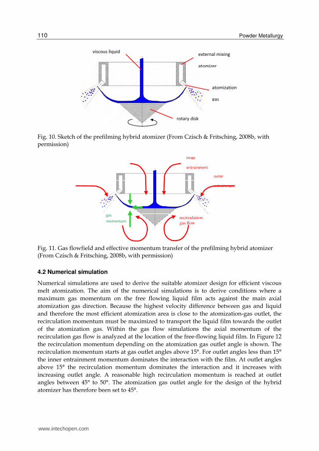
means of intrinsic aerodynamic forces in the gas flow field. In Fig. 10 the principle of the
prefilming hybrid atomizer is illustrated. To ensure stable atomization, aerodynamic forces
are used to protect the atomizer body from coming into contact and being blocked by parts
of the liquid (melt). A sufficiently small gas mass flow rate from the inside of the atomizer
protects the atomizer body.
The flow field of gas and liquid of the prefilming hybrid atomizer is illustrated in Fig. 11.
Different local flow regimes need to be distinguished. The inner entrainment reaches the
atomization area through the atomizer liquid stream passage. The outer entrainment
reaches the atomization area directly, and the recirculation gas flow reaches the atomization
area from below the rotary disc. All flow regimes are initialized be the atomization gas. The
film movement mainly depends on the acting aerodynamic and inertial forces caused by the
momentum distribution of the inner entrainment flow, the recirculation gas flow
momentum, and the film momentum itself. The aim of the prefilming hybrid atomizer
design is to generate a maximum recirculation momentum where the liquid film is
transported close to the gas outlet.
www.intechopen.com
Powder Metallurgy
110
viscous liquid external mixing
atomizer
atomization
gas
rotary disk
Fig. 10. Sketch of the prefilming hybrid atomizer (From Czisch & Fritsching, 2008b, with permission)
gas
momentum recirculation
gas flow
outer
entrainment
inner
entrainment
Fig. 11. Gas flowfield and effective momentum transfer of the prefilming hybrid atomizer (From Czisch & Fritsching, 2008b, with permission)
4.2 Numerical simulation
Numerical simulations are used to derive the suitable atomizer design for efficient viscous
melt atomization. The aim of the numerical simulations is to derive conditions where a
maximum gas momentum on the free flowing liquid film acts against the main axial
atomization gas direction. Because the highest velocity difference between gas and liquid
and therefore the most efficient atomization area is close to the atomization-gas outlet, the
recirculation momentum must be maximized to transport the liquid film towards the outlet
of the atomization gas. Within the gas flow simulations the axial momentum of the
recirculation gas flow is analyzed at the location of the free-flowing liquid film. In Figure 12
the recirculation momentum depending on the atomization gas outlet angle is shown. The
recirculation momentum starts at gas outlet angles above 15°. For outlet angles less than 15°
the inner entrainment momentum dominates the interaction with the film. At outlet angles
above 15° the recirculation momentum dominates the interaction and it increases with
increasing outlet angle. A reasonable high recirculation momentum is reached at outlet
angles between 45° to 50°. The atomization gas outlet angle for the design of the hybrid
atomizer has therefore been set to 45°.
www.intechopen.com

Hybrid Gas Atomization for Powder Production
111
x r
-45
-40
-35
-30
-25
-20
-15
-10
-5
0
0 20 40 60
atomization gas angle [0]
reci
rcu
lati
on
mo
men
tum
.
[kg
m/s
]
p = 0,89bar
p = 1,78bar
p = 2,64bar
analyzed
area
0.89bar
1.78bar
2.64bar
Fig. 12. Axial recirculation momentum on the free flowing film (From Czisch & Fritsching, 2008b, with permission)
r
h =10mm
D = 124mm
drota120m
tnozzle = 0
xt
d
d
t t nozzle
Spacing
Fig. 13. The constructive parameters of the hybrid atomizer design (From Czisch & Fritsching, 2008b, with permission)
In the same way as the gas outlet angle, all constructive parameters of the atomizer have
been determined separately by variation runs within the simulation. In Figure 13 the
resulting optimum parameter set for the prefilming hybrid atomizer is shown. The design is
based for the atomization of mineral melts at a temperature of 1873 K where the liquid
viscosity is 1 Pas and the melt mass flow rate is aimed at 300 kg/h. A gas jet spacing of 0 has
been chosen, therefore a slit nozzle is used as gas-flow exit geometry.
4.3 Model experiments
In Figures 14 and 15 experimental results of atomization of water and glycerol are illustrated. The mass median droplet size in the spray measured by laser diffraction is plotted against the air-to-liquid mass-flow ratio (ALR). The efficiency of the hybrid atomizer is evaluated in comparison with a conventional free-fall atomizer (Lohner et al, 2003). The free-fall atomizer is a common device for powder production (Bauckhage & Fritsching, 2000) and spray forming applications (Fritsching and Bauckhage, 2006). When low viscous
www.intechopen.com

Powder Metallurgy
112
liquid as e.g. water is atomized, the efficiency of the hybrid atomizer is low. For a constant liquid-mass flow rate, at identical ALR the hybrid atomizer produces coarser particle sizes. In this case the increase of the specific surface energy before atomization is not an advantage. It becomes advantageous only when the viscosity increases. Fig. 15 shows that at constant ALR, the hybrid atomizer produces finer particles than a conventional atomizer for viscous glycerol atomization. In this case, a mass-median particle size of less than 30 µm is achieved.
0
50
100
150
200
250
300
350
0 0,5 1 1,5 2 2,5
ALR [-] .
ma
ss m
edia
n p
art
icle
siz
e .
d 5
0,3
[µ
m]
.
conv. 400kg/h
conv. 700kg/h
conv. 1000kg/h
hyb. 400kg/h
hyb. 700kg/h
hyb. 1000kg/h
Fig. 14. Experimental results for atomizing water by air (From Czisch & Fritsching, 2008b, with permission)
0
50
100
150
200
250
300
350
0 0,5 1 1,5 2 2,5
ALR [-] .
ma
ss m
edia
n p
art
icle
siz
e .
d 5
0,3
[µ
m]
.
conv. 395kg/h
conv. 710kg/h
conv. 1001kg/h
hyb. 414kg/h
hyb. 696kg/h
hyb. 1007kg/h
Fig. 15. Experimental results for atomizing glycerol by air (From Czisch & Fritsching, 2008b, with permission)
4.4 Melt atomization experiments
For atomizing viscous melts by the hybrid atomizer concept, a pilot plant for hot-gas atomization has been used (Lohner at al., 2005). The main part of the plant is a spray tower (about 5.5 m in height). On top of the spray tower, the material is melted by an induction heating device. As material to be atomized, a blast-furnace slag is used for the trials. The melt temperature before atomization is measured as 1813-1843 K with a mean temperature of 1826 K. Through the bottom pouring crucible, the melt flows out due to gravity at melt-mass flow rates up to 300 kg/h. The hybrid atomizer located underneath the crucible is operated using heated gas. Gas temperatures up to 1273 K and gas pressures up to 2 bar
www.intechopen.com
Hybrid Gas Atomization for Powder Production
113
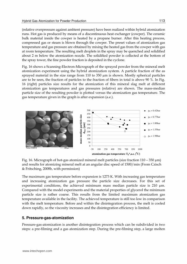
(relative overpressure against ambient pressure) have been realized within hybrid atomization runs. Hot gas is produced by means of a discontinuous heat exchanger (cowper). The ceramic bulk material inside the cowper is heated by a propane burner. After this heating process, compressed gas or steam is blown through the cowper. The preset values of atomization gas temperature and gas pressure are obtained by mixing the heated gas from the cowper with gas at room temperature. The resulting melt droplets in the spray may be quenched and solidified about 2 m below the atomization nozzle. The solidified powder is collected at the bottom of the spray tower, the fine powder fraction is deposited in the cyclone.
Fig. 16 shows a Scanning-Electron-Micrograph of the sprayed powder from the mineral melt atomization experiment using the hybrid atomization system. A particle fraction of the as sprayed material in the size range from 110 to 350 µm is shown. Mostly spherical particles are to be seen, the fraction of particles to the fraction of fibers in total is above 90 %. In Fig. 16 (right) particles size results for the atomization of this mineral slag melt at different atomization gas temperatures and gas pressures (relative) are shown. The mass-median particle size of the resulting powder is plotted versus the atomization gas temperature. The gas temperature given in the graph is after expansion (a.e.).
0
50
100
150
200
250
300
350
400
450
500
-50 100 250 400 550 700 850 1000
atomization gas temperature T0*,a.e. [0C]
mass
med
ian
part
icle
siz
e .
d50,3
[µ
m]
p0 = 0.42bar
p0 = 0.77bar
p0 = 1.00bar
p0 = 1.55bar
p0 = 1.98bar
Fig. 16. Micrograph of hot-gas atomized mineral melt particles (size fraction 110 – 350 µm) and results for atomizing mineral melt at an angular disc speed of 1500/min (From Czisch & Fritsching, 2008b, with permission)
The maximum gas temperature before expansion is 1273 K. With increasing gas temperature
and increasing atomization gas pressure the particle size decreases. For this set of
experimental conditions, the achieved minimum mass median particle size is 210 µm.
Compared with the model experiments and the material properties of glycerol the minimum
particle size is rather coarse. This results from the limited maximum atomization gas
temperature available in the facility. The achieved temperature is still too low in comparison
with the melt temperature. Before and within the disintegration process, the melt is cooled
down rapidly, so the viscosity increases and the disintegration efficiency is limited.
5. Pressure-gas-atomization
Pressure-gas-atomization is another disintegration process which can be subdivided in two steps: a pre-filming and a gas atomization step. During the pre-filming step, a large molten
www.intechopen.com

Powder Metallurgy
114
metal surface is generated to prepare an efficient second disintegration step by gas atomization. In the following, the development, the principle, and the results of the pressure-gas-atomization are described.
5.1 Principle
Pressure-gas-atomization became possible after the development of the pressure atomizer.
The idea of a pressure atomizer for molten metal was born in the 90`s by Sheikhaliev and
later published by Dunkley and Sheikhaliev (Dunkley & Sheikhaliev, 1995). Originally, the
authors called this atomization technique “Centrifugal Hydraulic Atomization”. Here, the
metal was melted in a crucible placed in a pressure vessel and the molten metal was
tangentially fed into a small swirl chamber where the molten metal starts to rotate.
Typically, on the centreline of the swirl chamber a gas core develops due to centrifugal
forces. Finally, at the lower end of the conical part of the swirl chamber a hole with a
diameter between 1 and 2 mm allows the melt to leave the swirl chamber as a thin film
creating a hollow cone inside the spray chamber (fig. 17). Normally, a pressure difference of
0.4 to 1.0 MPa between the pressure vessel and the spray chamber is sufficient to achieve a
hollow cone of a molten metal. Commonly, this principle is used for cold liquids as an
effective atomization system. For a long time, it was doubted if this principle can be applied
to molten metal because of their much higher surface tension and the nozzle heating was
another challenge. Finally, the molten melt film becomes instable and disintegrates to
ligaments and relatively large droplets (mass median diameter far above 100 µm).
10mm
Fig. 17. Schematic (above) and picture (below) of pressure atomization using pure tin (Achelis, 2009).
The pressure-gas-atomization was developed to achieve smaller particles and a narrow size distribution. It combines the pressure atomization as a pre-filming step and the gas atomization. As the second step a gas-ring-atomizer is used to disintegrate the molten metal film, ligaments, and any large droplets. This idea results in a patent published in 2002 (Uhlenwinkel, 2002) and initiated intensive investigations (Lagutkin et al., 2003b, 2004b;
www.intechopen.com

Hybrid Gas Atomization for Powder Production
115
Achelis et al., 2006, 2008, 2009). The hollow cone film/spray is surrounded by the gas-ring-atomizer. Due to the high velocity gas flow from the gas-ring-atomizer, the hollow cone spray from the pre-filming process is atomized into small droplets. Simultaneously, the particles are mainly directed to the centreline of the atomizer axis (Fig. 18).
Fig. 18. Schematic (left) and pressure-gas-atomization of pure tin (right), (Achelis et al., 2006a).
5.2 Pre-filming
A pressure difference of about 0.4 MPa is necessary to achieve a fully developed hollow cone if pure tin is used. Fig. 19 shows the effect of the pressure on the cone angle. A fully developed cone is already achieved with a pressure of 0.45 MPa but the cone angle Θ is still small (29°). Higher pressure yields in a large cone angle as demonstrated in the figure as well.
Fig. 19. Effect of the pressure pL on the spray cone angle Θ during pressure-atomization of pure tin (Achelis, 2009).
A high speed video camera was used to investigate the break-up of the liquid metal film. The pictures in fig. 20 represent single images of different alloys. The image section shows the area below the gas-ring-atomizer (not in use). The tin film is hidden by the gas-ring-atomizer and only the ligaments of the oscillating film are seen below the gas ring nozzle.
www.intechopen.com

Powder Metallurgy
116
Verfahrensprinzip: Druck-Zerstäubung
Sn SnCu30 AlSi12
Alloy
Images from high speed video camera
Recording frequency; 63 000 frames/s
10 mm
Fig. 20. Break-up of liquid metal films using several alloys. Different film length and break-up mechanism (Achelis et al., 2010).
From the ligaments multiple droplets are generated which are clearly visible below the gas-ring-atomizer. The film break-up of the SnCu30 alloy is totally different. The film can be recognized as the dark area with some bright reflection zones at the surface. The film length is much longer compared to pure tin and the break-up mechanism is dominated by a perforation of the film. The holes in the film grow quickly until only ligaments are left which will break into multiple droplets as well. Finally, the last image (right) shows that the metal film of the AlSi12 alloy is again longer. Bright areas on the surface are just reflections. The spray cone is not fully developed which is indicated by the non-conical shape of the cone. A higher pressure pL is necessary to achieve a fully developed hollow cone for this alloy.
5.3 Gas flow in the vicinity of the gas-ring-atomizer
The gas flow generated by the gas ring atomizer has been studied carefully for the design of the atomizer. The gas-ring-atomizer can induce strong recirculation zones which can affect the atomization and result in an instable process. Simple pressure measurements on the centreline of the atomizer can help to understand the gas flow in the vicinity of the gas-ring-atomizer. Fig. 21 shows the pressure on a tube surface located on the centreline using different gas-ring-atomizer designs. The location and the intensity of the maximum pressure indicate the risk of recirculation zones. The highest risk is given for the ring slit nozzle with a maximum pressure value of 25 kPa just 10 mm below the gas-ring-atomizer. The other atomizers have several discrete holes with different exit angles and same total exit areas of 18.5 mm². An angle of 0° represents the direction straight downwards.
The flow situation was also studied by using water as fluid instead of molten metal. To get an interior view of the spray cone a laser light sheet was used to illuminate the central plane of the spray cone (Fig. 22). White arrows exhibit the exit and direction of the gas jets. Obviously, the ring slit nozzle attacks the water film from the pressure nozzle directly and droplets come very close to the gas nozzle. In case of molten metal this will lead to an instable process. This result corresponds to the pressure measurements in the figure before. Therefore, discrete holes in the ring gas atomizer are preferred for pressure-gas-atomization. An exit angle of 0° was chosen for the atomization of molten metal.
www.intechopen.com

Hybrid Gas Atomization for Powder Production
117
nozzle exit angle +15°, exit area 18.5mm²
nozzle exit angle 0°, exit area 18.5mm²
nozzle exit angle -15°, exit area 18.5mm²
Ring nozzle with 0°, exit area 19.1mm²
Pre
ssu
red
iffe
ren
ceΔp
[k
Pa
]
Distance from the gas nozzle z [mm]
Fig. 21. Pressure on the surface of a tube placed on the centreline of the gas-ring-atomizer indicates the gas flow field in the vicinity of the atomizer. The effect of different atomizer designs is shown (Lagutkin et al., 2003a/b).
10mm
z
+15 0 -15 0 (ring slit)
Gas nozzle exit angle β in °
Central plane of the spray cone illuminated by a laser light sheet
Pressure gas atomization, fluid: water
Bright area = high amount of particles
β
Fig. 22. Influence of different atomizer designs on the spray cone of a pressure-gas-atomizer. The central plane of the spray cone is illuminated by a laser light sheet and water is used as a liquid (Uhlenwinkel et al., 2003).
5.4 Melt flow rate
The production rate is an important feature for an atomization processes. Typically the mass
flow of the pressure gas atomization can be varied between 70 and 200 kg/h using tin and
tin-copper alloys. As expected, the melt flow rate can be adjusted by the pressure difference
between the pressure vessel and the spray chamber. The gas pressure in the gas-ring-
atomizer does not influence the melt flow.
www.intechopen.com

Powder Metallurgy
118
5.5 Particle size
Typically, the mass median diameter without gas atomization (only pressure-atomizer) are in the range of 400 to 500 µm. The gas to metal ratio (GMR, here in kg gas / kg melt) is the key parameter to control the mean particle size. Fig. 23 shows that already with low GMR (below 1.0) the mass median diameter can be varied between 40 and 100 µm for pure tin. Even mean particles sizes of approximately 20 µm can be achieved. An increase of the copper content up to 50 weight percent does not make a big difference to the mass median diameter. Only a copper content of 63 weight percent results in larger mean particle sizes. It is assumed the higher surface tension is the main reason for this behavior. All measurements were accomplished by laser diffraction. A superheat of 100 K in the crucible was enough to achieve mostly spherical particles.
Druck-Gas-Zerstäuber
Ma
ssm
ed
ian
dia
me
ter
d5
0,3
[µm
]
Gas to metal ratio (GMR)
Fig. 23. Effect of the GMR on the mass median diameter for different alloys. The superheat TS was almost 100K above the liquidus temperature of the alloy (Achelis et al., 2009).
Normally, the size distribution is characterized by another parameter, for example the geometric standard deviation σg = d84,3/d50,3 = d50,3/d16,3 . Both values are the same if the distribution follows a log-normal size distribution. Here, the standard deviation is defined as σg = d84,3/d50,3. The results in fig. 24 are plotted versus the mass median diameter. Obviously, the geometric standard deviation depends on the mean particle size and a low mean particle size results in a higher geometric standard deviation. This holds for pure tin and this tin-copper alloys as well. A standard deviation below 2.0 achieved by a gas atomization technique is considered extremely good.
Of course, there are other parameters effecting the particle size distribution, specially the design of the atomizers. But the examples shown are representative. The mass median diameter can be calculated by the following semi-empirical equation (Achelis, 2009):
37.05.0
2
4.0
1.06.0
23,50
360101.0107.045.1
G
L
LL
L
G
L
G
L
GG
L
M
M
M
M
umd
(1)
Here, the mass median diameter d50,3 (in m) depends on the surface tension σL, density ┩L and viscosity ηL of the melt, the gas density ┩G, the gas velocity uG at a distance of 25 mm
www.intechopen.com

Hybrid Gas Atomization for Powder Production
119
Fig. 24. Geometric standard deviation σg versus the mass median diameter d50,3 for different alloys to characterize the particle size distribution of a pressure-gas-atomization (Achelis et al., 2010).
from the orifice, the film thickness δ, the melt and gas mass flow GM and LM , and the spray
cone angle Θ. The film thickness is calculated from the equation given in (Rizk & Lefebvre,
1985 cited in Achelis, 2009) for a pressure atomizer:
LL
LLL
p
MD
66.3
(2)
In equation (2) DL means the exit diameter of the nozzle.
5.6 Particle velocity
Particle velocities are of interest for the verification of process modeling and for the
calculation of cooling and solidification rates. Several measuring techniques are available to
measure the particle velocity in the spray cone (e.g. Laser Doppler Anemometry LDA, Phase
Doppler Anemometry PDA, Particle Image Velocimetry PIV). Some results of a PDA
measurement are presented in fig. 25. Here, the mean velocity on the centreline of the spray
cone is plotted versus the gas pressure in the gas-ring-atomizer at a distance of 165 mm. The
molten tin was superheated to a temperature of 275 °C and the melt flow reached 180 kg/h.
The variation of the gas pressure resulted in a gas mass flow range between 117 and 198
kg/h. Because of the increased gas flow the mean particle size was reduced and both higher
gas velocities and smaller particles added up to mean particle velocity between 70 and 135
m/s.
5.7 Particle shape
Generally, inert gas atomized metal show spherical shape. Therefore, the mean circularity C = 4┨ projection area / (perimeter)² of the particles is close to 1.0. But frequent collisions between liquid or semi-liquid droplets and solidified particles in the spray cone can result in
www.intechopen.com

Powder Metallurgy
120
Druck-Gas-Zerstäuber
Me
an
pa
rtic
lev
elo
city
[m/s
]
Pressure in the gas nozzle [MPa]
Fig. 25. Correlation between pressure in the gas nozzle and mean particle velocity on the centreline for pure tin measured by Phase-Doppler-Anemometry (Lagutkine et al., 2004a)
agglomerations and/or multiple small particles (satellites) attached to a bigger one. This will reduce the flowability of the powder which is an important quality feature. Often, satellites occur because of the gas flow in the spray chamber. Close to the wall of the spray chamber the gas velocity direction is contrary to the main flow direction and small particles are transported to the spray cone again and collide with the droplets. This recirculation zone inside the spray chamber can be avoided by a recirculation of the clean gas (after the particle collector (cyclone and/or filter) and the fan). The clean gas is added at the top of the spray chamber and - as a side effect – leads to a better visibility of the atomization process.
There appears to be a significant influence of the gas recirculation on the circularity of the powder (figure 26). With gas recirculation the mean circularity of the powder is very close to
Me
an
circ
ula
rity
[-]
Mass median diameter d50,3 [µm]
with gas recirculation
without gas recirculation
Fig. 26. Mean circularity versus mass median diameter with/without gas recirculation measured by image analysis (G3 Morphology, Malvern), (Achelis et al., 2010)
www.intechopen.com

Hybrid Gas Atomization for Powder Production
121
1.0 and the SEM picture on the right side confirms this result clearly. Without gas recirculation the circularity drops considerably and SEM figure shows the reason of this behavior in agglomerates and multiple satellites.
6. Conclusions and future Investigations
Gas atomization is the most versatile method to produce powders by atomization of a liquid melt. In this context, free-fall atomizers are external mixing gas atomizers based on a combination of a primary and a secondary gas nozzle. The primary gas stabilizes the atomization process and the secondary gas is used for atomization of the liquid. If only the secondary gas is used, a gas recirculation flow underneath the secondary nozzle occurs. This recirculation flow may cause the transport of atomized ligaments or droplets in the direction of the atomizer body. Liquid impinging on the atomizer body may clog the gas orifices and badly influence the atomizer performance. Thus in common free-fall atomizer design, the primary gas is used to suppress the recirculation flow and to stabilize the atomization process.
To improve the operating conditions and to overcome limitations of the free-fall atomizer, a Coanda-flow ring device was developed and installed inside the secondary gas flow. By using the Coanda-flow device, the secondary gas flow is deflected in the downward direction, the entrainment mass flow is increased, and, therefore, a primary gas nozzle is not necessary for suppression of gas recirculation. The concept was derived and verified by means of numerical gas flow simulations and model experiments. The application of the flow-adapted design option for free-fall atomizers was demonstrated by the atomization of a viscous melt. The results indicated a stable operation of the free-fall atomizer even at higher secondary gas pressures, as well as a finer particle yield.
The concept of a prefilming hybrid atomizer has been introduced. The atomizer is designed for atomizing highly viscous liquids and melts. Physical gas flow effects are utilized to increase the atomizer efficiency. The hybrid atomizer design is based on numerical flow simulations of the gas phase. Experiments where water a viscous model liquid (glycerol) a have been atomized with air show a higher disintegration efficiency than a conventional external mixing atomizer for the viscous liquid atomization process. Model experiments atomizing fluids of low viscosity like water show an insufficient atomization efficiency of the hybrid atomizer design. Thus the hybrid atomizer concept is a novel device for highly viscous liquids and melts. The experimental results for atomization of a mineral melt by heated gases underline the success of the hybrid atomization process with some limitations. For the present conditions, a minimum mass-median particle size of 210 µm has been achieved. The coarse product obtained by melt atomization is due to limitations of the available maximum atomization gas temperature and may be overcome in future developments.
The complexity of the pressure-gas-atomization is a drawback for frequent applications in industry. To overcome the problem the system can be simplified in the future if it is used with low melting point alloys. Today, pumps for molten metal like tin alloys are available and the complexity of the system can be reduced considerably because a pressure vessel is not necessary anymore and thus the process principally can operate continuously.
Another future objective is the use of the pressure-gas-atomizer for coating applications. It has already been proofed that this atomization system is dedicated to generate thick
www.intechopen.com

Powder Metallurgy
122
coatings on a tube. As an example a steel tube with a diameter of the 80 mm was coated with a 10 mm thick tin layer. The density of the coating was much better the than 99% of the full density (Uhlenwinkel et al., 2008).
7. Acknowledgments
The results that have been presented here are mainly based on the project work of several PhD students at the Particles and Process Engineering department of the University of Bremen. Namely the contributions of Dr.-Ing. L. Achelis, Dr.-Ing. S. Markus, Dr.-Ing. H. Lohner, Dr.-Ing. U. Heck, Dr. S. Pulbere and Dr.-Ing. C. Czisch are acknowledged. The cooperation in these fields with international colleagues, namely Dr. S. Lagutkin, Prof. S. Sheikhaliev and Dr. V. Srivastava is greatfully acknowledged.
The financial support of the projects has been mainly given by the German Research Foundation (DFG), whose support during the past decade in several areas and through projects is greatfully acknowledged.
8. References
Achelis, L.; Uhlenwinkel, V.; Lagutkin S. & Sheikhaliev, S. (2006): Atomization Using a Pressure-Gas-Atomizer. Proceedings of the International Conference on Powder Metallurgy 2006, Busan (South Koria), Sept. 2006
Achelis, L. & Uhlenwinkel, V. (2008): Characterisation of metal powders generated by a pressure-gas-atomizer. MSE A 477 (2008), pp.15-20
Achelis L. (2009): Kombinierte Drall-Druck-Gaszerstäubung von Metallschmelzen. Shaker Verlag, Aachen 2009, ISBN 978-3-8322-8012-3
Achelis, L.; Sulatycki, K.; Uhlenwinkel, V. & Mädler, L. (2010): Spray angle and particle size in the pressure gas atomization of tin and tin-copper alloys, Proceeding of the International Conference on Powder Metallurgy 2010, Florence (Italy), October 2010
Anderson, I.E. & Figliola, R.S. (1998). Observations of gas atomization process Dynamics, in Modern Developments in Powder Metallurgy, Gummeson, P.U. &Gustafson, D.A. Eds., Metal Powder Industries Federation, Princeton, N.J., Vol. 20, pp. 205–223
Ashgriz, N. (2011). Handbook of Atomization and Sprays, Springer, New York Bayvel, L. & Orzechowski, Z. (1993). Liquid Atomization, Taylor & Francis ,Washington Bauckhage, K. (1992). Das Zerstäuben metallischer Schmelzen, Chem.-Ing.-Tech., Vol. 64 No.
4, pp. 322–332 Bauckhage, K. & Fritsching U. (2000). in: K.P. Cooper, I.E. Anderson, S.D. Ridder, F.S.
Biancaniello (Eds.) Liquid Metal Atomization: Fundamentals and Practice, TMS, Warrendale, USA, pp. 23 – 36
Bergmann, D.; Fritsching, U. & Bauckhage, K. (2001) Simulation of molten metal droplet sprays, Comp. Fluid Dynamics-Journal, Vol. 9, pp. 203 – 211
Bradley, D. (1973). On the atomization of liquids by high-velocity gases, Part 1, J. Phys. D: Appl. Phys., Vol. 6, 1724–1736, Part 2, J. Phys. D: Appl. Phys., Vol. 6, pp. 2267–2272
Campanile, F. & Azzopardi, B.J. (2003). in: Cavaliere, A. (Ed) CD-ROM Proc. International Conference on Liquid Atomization and Spray Systems ICLASS 2003, Sorrento, Italy, 13-17.07.2003, ILASS-Europe
www.intechopen.com
Hybrid Gas Atomization for Powder Production
123
Czisch, C.; Lohner, H.; Fritsching, U., Bauckhage, K. & Edlinger, A. (2003). in: K. Bauckhage, U. Fritsching, J. Ziesenis, A. Uhlenwinkel, A. Leatham (Eds), Proc. Spray Deposition and Melt Atomization Conf. SDMA 2003, Bremen, 22.-25.6.2003
Czisch, C.; Lohner, H. & Fritsching, U. (2004). Einfluss der Gasdüsenanordnung auf den Desintegationsvorgang und das Zerstäubungsergebnis bei der Zweistoff-zerstäubung, Chem.-Ing.-Tech., Vol. 76, No. 6, pp. 754-757
Czisch, C. & Fritsching, U. (2008a). Flow-adapted design for Free-fall atomizers, Atomization and Sprays, Vol. 18 No. 6, pp. 511-522
Czisch, C. & Fritsching, U. (2008b). Atomizer design for viscous-melt atomization, Mat. Sci. Engng. A Vol. 477 No. 1-2, pp. 21-25
Dombrowski, N. & Johns, W.R. (1963). Chem. Eng. Sci., Vol. 3, pp. 203-214 Dunkley, J.J. & Sheikhaliev, S. (1995): Single Fluid Atomization of Liquid Metals, Proceedings
of the International Conference on Powder Metallurgy & Particulate Materials, Seattle (USA), May 1995, Vol. 1, pp. 79-87
Dunkley J.J. (2001). in: 2001 International Conference on Powder Metallurgy and Particulate Materials PM2TEC 01, 2-29-2-35, 2001, Metal Powder Industries Federation, Princeton, USA
Fraser, R.P.; Dombrowski, N. & Routley, J.H. (1962). Chem. Eng. Sci., Vol. 18, pp. 339-353 Fritsching, U. & Bauckhage, K. (1992). Investigations on the atomization of molten metals:
The coaxial jet and the gas flow in the nozzle near field, PHOENICS J. Comp. Fluid Dynamics, Vol. 5, No. 1, pp. 81-98
Fritsching, U. (2004). Spray Simulation: Modeling and Numerical Simulation of Sprayforming Metals, Cambridge University Press, Cambridge, UK
Fritsching, U. & Bauckhage, K. (2006a). Sprayforming of Metals, in: Ullmann´s Encyclopedia of Industrial Chemistry, 7th Edition, 2006 Electronic Release, Wiley VCH, Weinheim, Germany
Fritsching, U. (2006b). Spray Systems, in: Multiphase Flow Handbook, Ed.: C.T. Crowe, CRC-Press, Boca Raton, Fl, USA, 2006, Chapter 8, pp. 8.1 - 8.100; ISBN: 0849312809
Heck, U. (1998). Zur Zerstäubung in Freifalldüsen, VDI Verlag GmbH Düsseldorf, Germany Heck, U.; Fritsching, U. & Bauckhage, K. (2000). Gas-Flow Effects on Twin-Fluid
Atomization of Liquid Metals, Atomization and Sprays, Vol. 10, No. 1, pp. 25 – 46 Lagutkin, S.; Achelis, L.; Sheikaliev, S.; Uhlenwinkel, V. & Srivastava V. (2003a):
Atomisation Process for Metal Powder. Proceedings of the International Conference on Spray Deposition and Melt Atomization 2003, Bremen (Germany), June, 2003,
Lagutkin, S. (2003b): Development of Technology and Equipment for Metal Powder Production by Centrifugal-Gas Atomization of Melt. Ph.D. thesis. Ekaterinburg, Ural Department of Academy of Sciences. 2003, in Russian
Lagutkin, S.; Uhlenwinkel, V.; Achelis, L.; Pulbere, S. &. Sheikhaliev S. (2004a): Centrifugal-Gas Atomization: Preliminary Investigation of the Method, Proc. International Conference on Powder Metallurgy 2004, Wien, Austria, Oct. 2004, Vol. 1, S.71-76
Lagutkin, S.; Achelis, L.; Sheikhaliev, S.; Uhlenwinkel, V. & Srivastava V. (2004b): Atomization process for metal powder. MSE-A 383 (1), (2004), pp. 1-6
Lavernia, E.J. & Wu, Y. (1996). Spray Atomization and Deposition, J. Wiley & Sons, Chichester Lefebvre, A.H. (1980). Prog. Energy Combust. Sci., Vol. 6, pp. 233-261 Lefebvre, A.H. (1989). Atomization and Sprays, Hemisphere Publ. Corp., US
www.intechopen.com

Powder Metallurgy
124
Liu, H. (2000) Science and Engineering of Droplets: Fundamentals and Applications, William Andrew Publ., Norwich, USA
Lohner, H. (2002). Zerstäuben von Mineralschmelzen mit Heißgas, PhD. thesis, University Bremen
Lohner, H.; Czisch, C. & Fritsching, U. (2003). Impact of Gas Nozzle Arrangement on the Flow Field of a Twin Fluid Atomizer with External Mixing, Int. Conf. on Liquid Atomization and Spray Systems, Sorrento, Sep. 2003 (Italien)
Lohner, H.; Czisch, C.; Schreckenberg, P.; Fritsching, U. & Bauckhage, K. (2005). Atomization of viscous melts, Atomization and Sprays, Vol. 15, No. 2, pp. 169-180
Markus, S.; Fritsching, U. & Bauckhage, K. (2002). Jet Break Up of Liquid Metals in Twin Fluid Atomization, Materials Sci. & Engng. A, No. 326, pp. 122 – 133
Pickering, S.J.; Hay, N.; Roylance, T.F. & Thomas, G.H. (1985). Ironmaking and Steelmaking, Vol. 12 No. 1
Rizk, N.K. & Lefebvre A.H. (1985) : Internal Flow Characteristics of Simplex Swirl Atomizer. Journal of propulsion and power, Vol. 1 (1985) No. 3, New York, pp. 193-199
Strauss, J.T. (1999). Hotter gas increases atomization efficiency, Metal Powder Report, Vol. 11, pp. 24-28
Uhlenwinkel, V. & Sheikhaliev S., et al. (2002): Verfahren und Vorrichtung zum Herstellen von Metallpulver und keramischem Pulver, Pat.Nr. 10237213, 14.Aug. 2002
Uhlenwinkel, V.; Achelis, L.; Sheichaliev, S. & Lagutkin, S. (2003): A new Technique for Molten Metal Atomization. Proc. ICLASS 2003, Sorento, Italy, June, 2003
Uhlenwinkel, V.; Achelis, L. & Mädler, L. (2008): New atomization process to achieve high production rates during thermal spraying of thick coatings, Proceedings of the International Thermal Spray Conference 2008, Maastricht (Netherlands), June 2008
Wille, R. Fernholz, H. (1965). Report on the First European Mechanics Colloquium on the Coanda Effect, J. Fluid Mech., Vol. 23, pp. 801-819
Yule, A.J. & Dunkley J.J. (1994). Atomization of Melts, Clarendon Press Oxford, UK
www.intechopen.com

Powder MetallurgyEdited by Dr. Katsuyoshi Kondoh
ISBN 978-953-51-0071-3Hard cover, 124 pagesPublisher InTechPublished online 09, March, 2012Published in print edition March, 2012
InTech EuropeUniversity Campus STeP Ri Slavka Krautzeka 83/A 51000 Rijeka, Croatia Phone: +385 (51) 770 447 Fax: +385 (51) 686 166www.intechopen.com
InTech ChinaUnit 405, Office Block, Hotel Equatorial Shanghai No.65, Yan An Road (West), Shanghai, 200040, China
Phone: +86-21-62489820 Fax: +86-21-62489821
From high-performance, economical and environmental points of view, Powder metallurgy process showsremarkable advantages in production of parts and components due to their special compositions by elementalmixing and 3-dimensional near net shape forming methods. Powder metallurgy process can be applied to notonly metal materials but also ceramics and organic materials, which both are employed as structural andelectrical products. Author contributions to Powder metallurgy present excellent and significantly importantresearch topics to evaluate various properties and performance of P/M materials for applying these materialsas actual components. In particular, the life estimation of P/M ferrous materials by sliding contact fatigue testand tribological performance evaluation of P/M semi-metallic materials are focused and introduced in thisbook.
How to referenceIn order to correctly reference this scholarly work, feel free to copy and paste the following:
Udo Fritsching and Volker Uhlenwinkel (2012). Hybrid Gas Atomization for Powder Production, PowderMetallurgy, Dr. Katsuyoshi Kondoh (Ed.), ISBN: 978-953-51-0071-3, InTech, Available from:http://www.intechopen.com/books/powder-metallurgy/hybrid-gas-atomization-for-powder-production

© 2012 The Author(s). Licensee IntechOpen. This is an open access articledistributed under the terms of the Creative Commons Attribution 3.0License, which permits unrestricted use, distribution, and reproduction inany medium, provided the original work is properly cited.