Hybrid Exact-Approximate Analytic Hypersonic Aerodynamic ...Hybrid Exact-Approximate Analytic...
14
Hybrid Exact-Approximate Analytic Hypersonic Aerodynamic Relations for General Vehicle Shapes Michael J. Grant ⇤ Purdue University, West Lafayette, IN, 47906 This study investigates the creation of hybrid exact-approximate, analytic hypersonic aerodynamic relations for a wide range of vehicle classes to support conceptual design. This is accomplished by performing exact, analytic integrations of the Newtonian pres- sure coefficient over the unshadowed surface of the vehicle where possible and analytically approximating the remaining terms. Comparisons with a panel method validate the ana- lytic solutions formed for arbitrary bodies of revolution with profiles described by second-, third-, or fourth-order Bezier curves as well as non-axisymmetric geometries described by constrained second-order Bezier surfaces. The computational and design advantages pro- vided by the analytic relations enable the rapid design of vehicle shape within conceptual studies in manner that is not possible with traditional panel methods. Nomenclature ˆ n in inward normal vector B control node location, m P Bezier function, m r position of di↵erential surface element, m A ref reference area, m 2 C A axial force coefficient C l roll moment coefficient C m pitch moment coefficient C N normal force coefficient C n yaw moment coefficient C p pressure coefficient C S side force coefficient n order of Bezier curve N u number of discrete elements along u N v number of discrete elements along v p 1 freestream pressure, Pa u arclength, surface parametrization variable v surface parametrization variable V 1 freestream velocity magnitude, m/s ⇢ 1 freestream density, kg/m 3 ✓ inclination angle, rad I. Introduction and Motivation Traditionally, multidisciplinary hypersonic conceptual design is performed in a sequential, iterative de- sign environment comprised of independently developed disciplinary analyses. In this environment, design variables are separately chosen within each discipline. As a result, the interaction among cross-discipline variables is segregated, limiting the use of fast, specialized optimization methods in favor of slower, more generalized methods. Typically, the early phases of conceptual hypersonic design are executed to identify the type and configuration of the vehicle as well as the corresponding envelope of trajectory capability. With this consideration, hypersonic vehicle capability is generally identified through iteration among vehicle shape, aerodynamic performance, and trajectory optimization routines as shown in Fig. 1. This sequential, iterative process is the result of a fundamental segregation between vehicle shape and trajectory optimization routines that results from the characterization of aerodynamic performance for each vehicle shape using large ⇤ Assistant Professor, School of Aeronautics and Astronautics, AIAA Member. 1 of 14 American Institute of Aeronautics and Astronautics Downloaded by PURDUE UNIVERSITY on January 13, 2014 | http://arc.aiaa.org | DOI: 10.2514/6.2013-4503 AIAA Atmospheric Flight Mechanics (AFM) Conference August 19-22, 2013, Boston, MA AIAA 2013-4503
Transcript of Hybrid Exact-Approximate Analytic Hypersonic Aerodynamic ...Hybrid Exact-Approximate Analytic...
Hybrid Exact-Approximate Analytic Hypersonic
Aerodynamic Relations for General Vehicle Shapes
Michael J. Grant⇤
Purdue University, West Lafayette, IN, 47906
This study investigates the creation of hybrid exact-approximate, analytic hypersonic
aerodynamic relations for a wide range of vehicle classes to support conceptual design.
This is accomplished by performing exact, analytic integrations of the Newtonian pres-
sure coe�cient over the unshadowed surface of the vehicle where possible and analytically
approximating the remaining terms. Comparisons with a panel method validate the ana-
lytic solutions formed for arbitrary bodies of revolution with profiles described by second-,
third-, or fourth-order Bezier curves as well as non-axisymmetric geometries described by
constrained second-order Bezier surfaces. The computational and design advantages pro-
vided by the analytic relations enable the rapid design of vehicle shape within conceptual
studies in manner that is not possible with traditional panel methods.
Nomenclature
n̂in inward normal vectorB control node location, mP Bezier function, mr position of di↵erential surface element, mA
ref
reference area, m2
C
A
axial force coe�cientC
l
roll moment coe�cientC
m
pitch moment coe�cientC
N
normal force coe�cientC
n
yaw moment coe�cient
C
p
pressure coe�cientC
S
side force coe�cientn order of Bezier curveN
u
number of discrete elements along u
N
v
number of discrete elements along v
p1 freestream pressure, Pau arclength, surface parametrization variablev surface parametrization variableV1 freestream velocity magnitude, m/s
⇢1 freestream density, kg/m3✓ inclination angle, rad
I. Introduction and Motivation
Traditionally, multidisciplinary hypersonic conceptual design is performed in a sequential, iterative de-sign environment comprised of independently developed disciplinary analyses. In this environment, designvariables are separately chosen within each discipline. As a result, the interaction among cross-disciplinevariables is segregated, limiting the use of fast, specialized optimization methods in favor of slower, moregeneralized methods. Typically, the early phases of conceptual hypersonic design are executed to identifythe type and configuration of the vehicle as well as the corresponding envelope of trajectory capability.With this consideration, hypersonic vehicle capability is generally identified through iteration among vehicleshape, aerodynamic performance, and trajectory optimization routines as shown in Fig. 1. This sequential,iterative process is the result of a fundamental segregation between vehicle shape and trajectory optimizationroutines that results from the characterization of aerodynamic performance for each vehicle shape using large
⇤Assistant Professor, School of Aeronautics and Astronautics, AIAA Member.
1 of 14
American Institute of Aeronautics and Astronautics
Dow
nloa
ded
by P
URD
UE
UN
IVER
SITY
on
Janu
ary
13, 2
014
| http
://ar
c.ai
aa.o
rg |
DO
I: 10
.251
4/6.
2013
-450
3
AIAA Atmospheric Flight Mechanics (AFM) Conference August 19-22, 2013, Boston, MA
AIAA 2013-4503

aerodynamic tables that are a function of vehicle orientation and flight conditions. As a result, this numeri-cal relationship has also segregated advancements in vehicle shape design from advancements in trajectoryoptimization.
Figure 1: Example design structure matrix for hy-personic performance characterization.
The hypersonic aerodynamics of vehicles are of-ten modeled during conceptual design using Newto-nian flow theory.1,2 This theory assumes that whena particle (traveling in rectilinear motion) strikes thesurface of a body, all of the momentum normal to thesurface would be lost and all momentum tangentialto the surface would be conserved as shown in Fig.2. Consequently, the pressure exerted by the fluid onthe surface of a body is assumed to be solely origi-nating from this loss of momentum normal to the sur-face. Under these assumptions, the nondimensionalpressure coe�cient, C
p
, at any point on the surfaceof a body can be obtained from the Newtonian sine-squared relation shown in Eq. (1). Furthermore, thepressure exerted by the fluid on any portion of the sur-face not directly exposed to the flow, denoted as theshadowed region of the body, is assumed to be equiv-alent to the freestream pressure in which the motion of the fluid does not influence the pressure in thisregion. Consequently, C
p
= 0 throughout the shadowed region as shown in Fig. 3. While this theory isonly accurate within continuum flow at high speeds, this flight condition is often achieved during trajec-tory segments with high dynamic pressure. As such, Newtonian flow theory is a reasonable approximationduring meaningful trajectory segments in which the vehicle has the greatest capability to alter its motion.The aerodynamic force and moment coe�cients are obtained by integrating the pressure coe�cient over theunshadowed surface of the vehicle.
C
p
=p� p112⇢1V
21
= 2 sin2 ✓ (1)
Figure 2: Momentum transfer of particle on inclinedsurface.2 Figure 3: Example of shadowed body.2
Traditionally, this integration is performed numerically through the use of ring methods3,4, 5 or panelmethods such as those included within the Configuration Based Aerodynamics (CBAERO) tool6 and theAerodynamic Preliminary Analysis System (APAS).7,8, 9 In this approach, the geometry of the vehicle isapproximated as a series of small flat plates, and the numerical integration is performed repeatedly across arange of orientations of interest to generate large aerodynamic tables. This procedure is repeated for eachvehicle shape analyzed during conceptual design, and the advent of the digital computer has resulted inwidespread adoption of panel methods.10,11 However, the analytic description of the flowfield (Eq. (1)) andrecent advances in symbolic tools such as Mathematica12 enable the surface integration to be performedanalytically. In prior work, analytic force and moment coe�cients were constructed for a wide range of basicshapes, including conical frustums, spherical segments, flat plates, and cylindrical segments.13 Additional
2 of 14
American Institute of Aeronautics and Astronautics
Dow
nloa
ded
by P
URD
UE
UN
IVER
SITY
on
Janu
ary
13, 2
014
| http
://ar
c.ai
aa.o
rg |
DO
I: 10
.251
4/6.
2013
-450
3

relations for quadratic- and parabolic-based shapes were also constructed through the use of boundary-volume techniques and other transformations.14,15,16 Since many hypersonic vehicles of interest can beconstructed through the superposition of these basic shapes as shown in Fig. 4,17,18,19,20,21,22 the hypersonicaerodynamics of these systems can also be expressed analytically through the appropriate combination ofthe analytic aerodynamic relations.
Figure 4: Example vehicles with analytic geometries.
Figure 5: Coupled hypersonic aerodynamic and tra-jectory system.
The analytic relations have been shown to be ap-proximately three orders of magnitude faster thanthe construction and evaluation of tables usingCBAERO.14 This speedup could be capitalized withintraditional, segregated design environments by replac-ing tables with the analytic relations. More impor-tantly, these relations provide an analytic mapping be-tween vehicle shape and trajectory performance. Sincethe analytic relations are generically parametrized byvehicle shape parameters and are applicable across allcorresponding geometries, vehicle shape parameterscan be directly incorporated into the equations of mo-tion as shown in Fig. 5 for an example sphere cone withnose radius r
n
, cone half angle �1, and base diameterd. In this example, the vehicle geometry is assumed tobe fixed during flight, but this framework could alsobe used with varying shape parameters as a result ofablation or configuration changes during flight. Notethat in this approach, the vehicle shape parametersare combined with trajectory states in a fully coupledmanner that eliminates the iteration between vehicleshape and trajectory that previously existed due tothe intermediate aerodynamic tables. This fully cou-pled system enables rapid indirect trajectory optimiza-tion principles to be extended to also include vehicleshape to perform rapid simultaneous hypersonic aero-dynamic and trajectory optimization in a manner thatis not possible within traditional segregated design en-vironments.14,23,24
While the previously developed analytic relationsenable the rapid design of various hypersonic systemsof interest, the range of geometries that have exact,analytic solutions are limited, and as a result, preventsthe adoption of these computationally e�cient relations into conceptual design studies. For many complex
3 of 14
American Institute of Aeronautics and Astronautics
Dow
nloa
ded
by P
URD
UE
UN
IVER
SITY
on
Janu
ary
13, 2
014
| http
://ar
c.ai
aa.o
rg |
DO
I: 10
.251
4/6.
2013
-450
3

shapes, no exact analytic force or moment solution can be constructed, and this is a consequence of thefundamental challenges that exist when performing complex integrations symbolically.14,15,16 To expandthe current analytic aerodynamic database to also include general vehicle configurations, hybrid exact-approximate analytic solutions are constructed for Bezier curves of revolution and Bezier surfaces. Note thatthese relations are generically parametrized by an appropriate set of control nodes. As such, the analyticrelations developed in this investigation are applicable across all configurations that can be representedby Bezier curves of revolution and Bezier surfaces. This is a major advantage over panel methods thatmust be executed each time the shape of the vehicle changes. The current analytic aerodynamic database,that includes the analytic relations derived in this investigation, can be downloaded from the followingembedded file when viewed in Adobe Acrobat ( )a. The enclosedMatlab routines should be referenced for the contents of the analytic expressions.
II. Hybrid Exact-Approximate Analytic Solutions
Exact, analytic relations are only constructed if every expression within the integration process hasa known integral. However, hybrid exact-approximate solutions can be constructed for general vehicleconfigurations that are also fully analytic. To support the rapid simultaneous design environment shown inFig. 5, each analytic aerodynamic expression must be valid across the entire range of both shadowed andunshadowed orientations. This requirement prevents the construction of fully approximate solutions thatspan the entire surface of the vehicle. As an example, consider a generic body with a surface parametrizationin u and v as shown in Eq. (2). With this surface parametrization, the inward unit normal, n̂in, can beformulated, and the pressure coe�cient can be computed using Eqs. (1), (3), and (4).
r = [f(u, v) g(u, v) h(u, v)]T (2)
n̂in =ru ⇥ rv
k ru ⇥ rv k (3)
sin(✓) = ˆ
V
T
1n̂in (4)
The integration of the pressure coe�cient over the surface of the vehicle could be approximated as shownin Eq. (5) for a force coe�cient in the x-direction, where S denotes the unshadowed surface of the vehicleand the di↵erential area is computed using Eq. (6). This procedure is analogous to the surface integrationperformed by a panel method. However, the approximation shown in Eq. (5) is performed directly on theaerodynamics of vehicle as opposed to the shape of the vehicle, providing a fully analytic approximation.Note that the finite sum in at least one variable changes as the orientation of the vehicle changes to accountfor the moving shadow boundary. As a result, the number of terms in the finite summation would vary orthe manner in which the surface quadrature is calculated would be altered due to the shift in node locationsfor each shadowed orientation, preventing the adoption of this analytic approximation within the designenvironment shown in Fig. 5. Alternatively, if one of the surface integrations can be performed analyticallyto allow for an analytic substitution of the shadow boundary (shown in Eq. (7)), then a single hybridexact-approximate analytic solution can be formulated that is valid across all shadowed and unshadowedorientations. This feature requires the shadow boundary to be fully determined by v as a function of u,allowing the approximation to be performed along u chosen to be constant regardless of the shadow boundary.This form enables the complex and changing shadow boundary to be incorporated analytically within thehybrid solutions. While a Riemann sum analogous to the calculations performed within a panel methodis shown in this example, any quadrature scheme could be used. For e�ciency, a Legendre-Gauss-Lobattoquadrature scheme is used in this investigation. Since the complexity of the integrated terms increaseswith the number of integration performed, this single exact integration procedure provides the greatestopportunity to construct analytic, hybrid exact-approximate solutions for general vehicle configurations. As
aPrior to unzipping the file, the ‘REMOVEME’ portion of the file extension must be removed.
4 of 14
American Institute of Aeronautics and Astronautics
Dow
nloa
ded
by P
URD
UE
UN
IVER
SITY
on
Janu
ary
13, 2
014
| http
://ar
c.ai
aa.o
rg |
DO
I: 10
.251
4/6.
2013
-450
3

such, the extent of general vehicle configurations that have analytic solutions of this form is investigated.
C
X
=1
A
ref
ZZ
S
C
p
n̂
T
inx̂ dA ⇡ 1
A
ref
NuX
i=0
NvX
j=0
C
p,{i,j} nin,{i,j}T
x̂ �A{i,j} (5)
dA =k n k=k r
u
⇥ r
v
k (6)
C
X
=1
A
ref
Zu2
u1
Zv2(u)
v1(u)C
p
n̂
T
inx̂ dA =1
A
ref
Zu2
u1
F (u) du ⇡ 1
A
ref
NuX
i=0
F (u) �u (7)
Unlike panel methods, the hybrid exact-approximate relations directly approximate the final aerodynamicresult, and the error of this result can be directly controlled to obtain a desired accuracy. Alternatively, panelmethods approximate vehicle shape to a certain level of accuracy, and the designer usually does not knowa priori how this approximation translates to the accuracy of the aerodynamic coe�cients. Consequently,multiple meshes of varying resolutions must be evaluated until convergence of the aerodynamic coe�cientsis observed.
II.A. Bezier Curves of Revolution
Many methods from computer-aided design exist to describe general shapes. As an initial step in thisdirection, analytic force and moment coe�cients have been developed for Bezier curves of revolution withvarious orders. While high-order analytic relations have been obtained, the resulting expressions are lengthy,limiting the computational e�ciency of this approach. While the e�ciency of these higher-order solutionscould likely be improved with symbolic manipulation (e.g., performing repeated calculations once and storingthe result in memory), solutions for second-, third-, and fourth-order Bezier curves of revolution are includedin this report. Note that these relations account for both shadowed and unshadowed angles of attack. Sincethese geometries are axisymmetric, the resulting analytic relations can be evaluated at total angles of attackand rotated to the proper wind frame to also account for nonzero sideslip angles (illustrated within theenclosed database).
0 0.5 1 1.5 20
0.5
1
1.5
2
2.5
x
r
2nd Order
3rd Order
4th Order
Figure 6: Bezier curves with control nodes and con-trol polygons.
The geometry of a Bezier curve is parametrizedby a nondimensional arclength, u, as shown in Eqs.(8)-(10) where 0 u 1.25 The location of the i
th
control node is specified by the vector Bi, and theorder of the Bezier curve is specified by n. The con-trol nodes specify a control polygon inside which theBezier curve must reside. While the analytic relationsare generically parametrized to control node locations,the use of Newtonian flow theory requires the evalu-ated shapes to be convex with a nondecreasing radiusalong the axis of the vehicle. Example second-, third-,and fourth-order Bezier curves, along with their corre-sponding control node locations and control polygons,are shown in Fig. 6. As expected, each Bezier curve re-sides inside the control polygon and is connected to theinitial and final control nodes in a tangential mannerto the control polygon. While the addition of controlnodes in higher-order solutions would provide greaterflexibility in describing the shape of the vehicle, it is apparent that substantially curved profiles can beachieved with a fourth-order Bezier curve. As such, the increase in computational resources beyond fourth-order solutions is likely not necessary during conceptual design. In fact, many conceptual design studiescould likely be accomplished with a low-order Bezier curve. To determine if low-order curves are su�cient
5 of 14
American Institute of Aeronautics and Astronautics
Dow
nloa
ded
by P
URD
UE
UN
IVER
SITY
on
Janu
ary
13, 2
014
| http
://ar
c.ai
aa.o
rg |
DO
I: 10
.251
4/6.
2013
-450
3

for a particular study, optimal solutions can be investigated with higher-order solutions until convergence insolution shape is observed.
P(u) =nX
i=0
Bi Jn,i(u) (8)
J
n,i
(u) =
✓n
i
◆u
i(1� u)n�i (9)
✓n
i
◆=
n!
i!(n� i)!(10)
0 0.5 1 1.5 20
0.5
1
1.5
2
2.5
x
r
Bezier Curve 1
Bezier Curve 2
Bezier Curve 3
Figure 7: Validated 2nd order Bezier curves.
The surface of a Bezier curve of revolution is mostnaturally parametrized along u (the nondimensional ar-clength along the Bezier curve) and v (the revolution an-gle of the Bezier curve) as described by Eq. (11), wherex(u) and r(u) are determined by expressions resultingfrom Eq. (8). In the derivation of these relations, theshadow boundary (where C
p
= 0) is fully incorporated forall angles of attack and sideslip by noting that the lim-its in the revolution angle, v, are calculated from inversetrigonometric functions. When the vehicle is fully ex-posed to the flow, the revolution angle inherits a nonzeroimaginary component. Thus, by evaluating the real com-ponent of this expression, valid limits in revolution an-gle are constructed that simultaneously account for bothshadowed and unshadowed angles of attack and sideslip.This property is essential in the construction of invariantanalytic expressions to support the coupled, multidisci-plinary design environment shown in Fig. 5. The analytic solutions to various second-order Bezier curvesshown in Fig. 7 are validated using a separately developed panel method as shown in Figs. 8-10. As shown,both sets of results are in excellent agreement. Note that each force and moment coe�cient as well as eachstability derivative is calculated from a single corresponding analytic solution. As such, the invariant setof analytic solutions is used to calculate all of the analytic aerodynamic data shown in Figs. 8-10. Whilethe analytic relations could be used to rapidly construct aerodynamic tables to support traditional concep-tual design environments, the analytic solutions also enable these shapes to be included within the rapid,simultaneous optimization framework as described in Section I.
r = [x(u) r(u) cos(v) � r(u) sin(v)]T (11)
0 50 1000
0.2
0.4
0.6
0.8
1
α, deg
CN
0 50 100
0.4
0.5
0.6
0.7
0.8
0.9
1
1.1
α, deg
CA
0 50 100−0.5
−0.45
−0.4
−0.35
−0.3
−0.25
−0.2
−0.15
−0.1
−0.05
α, deg
CS
Bezier Curve = 1
Bezier Curve = 2
Bezier Curve = 3
Bezier Curve = 1 (Panel)
Bezier Curve = 2 (Panel)
Bezier Curve = 3 (Panel)
Figure 8: Validated forces for 2nd order Bezier curves (� = 20o).
6 of 14
American Institute of Aeronautics and Astronautics
Dow
nloa
ded
by P
URD
UE
UN
IVER
SITY
on
Janu
ary
13, 2
014
| http
://ar
c.ai
aa.o
rg |
DO
I: 10
.251
4/6.
2013
-450
3

0 50 100−0.5
0
0.5
α, deg
Cl
0 50 100−0.4
−0.3
−0.2
−0.1
0
0.1
0.2
0.3
α, degC
m
0 50 100−0.5
0
0.5
α, deg
Cn
Bezier Curve = 1
Bezier Curve = 2
Bezier Curve = 3
Bezier Curve = 1 (Panel)
Bezier Curve = 2 (Panel)
Bezier Curve = 3 (Panel)
Figure 9: Validated moments for 2nd order Bezier curves (� = 20o).
0 50 100−0.8
−0.6
−0.4
−0.2
0
0.2
0.4
0.6
α, deg
Cm
,α
0 50 100−0.5
0
0.5
α, deg
Cn,β
Bezier Curve = 1
Bezier Curve = 2
Bezier Curve = 3
Bezier Curve = 1 (Panel)
Bezier Curve = 2 (Panel)
Bezier Curve = 3 (Panel)
Figure 10: Validated stability derivatives for 2nd order Bezier curves (� = 20o).
The third- and fourth-order Bezier curves shown in Figs. 11 and 12 are also validated using the panelmethod as shown in Figs. 13-16. As illustrated, excellent agreement exists for both the force and momentcoe�cients. Note that a small discrepancy in roll moment coe�cient (C
l
) is observed due to the full ap-proximation by the panel method. For axisymmetric bodies, the roll moment coe�cient should be zero, andthis result is obtained from the analytic relations. It is important to note that the stability derivatives ofthese higher-order curves are lengthy and not included. While the use of symbolic manipulation may enablethe construction of e�cient stability derivative expressions that are reasonably short in length, it may alsobe better to compute these derivatives numerically using a finite di↵erence or complex step method on thevalidated analytic moment expressions. Figs. 11 and 12 illustrate that these higher order curves provideadditional flexibility likely required to represent a range of blunt configurations. To achieve a fully bluntconfiguration, two control nodes must reside on the vertical axis as shown by the third Bezier curve in eachfigure. As an alternative, the front portion of sharp Bezier curves of revolution could be replaced with anappropriate spherical segment (of which analytic relations have already been developed),13 enabling the useof low-order Bezier cures for blunt configurations. Finally, as the bluntness of the vehicle increases, thecorresponding aerodynamic coe�cients may change dramatically as shown in Figs. 13 and 14. The analyticrelations are capable of capturing these large changes within each invariant expression.
7 of 14
American Institute of Aeronautics and Astronautics
Dow
nloa
ded
by P
URD
UE
UN
IVER
SITY
on
Janu
ary
13, 2
014
| http
://ar
c.ai
aa.o
rg |
DO
I: 10
.251
4/6.
2013
-450
3

0 0.5 1 1.5 20
0.5
1
1.5
2
x
r
Bezier Curve 1
Bezier Curve 2
Bezier Curve 3
Figure 11: Validated 3rd order Bezier curves.
0 0.5 1 1.5 2 2.50
0.5
1
1.5
2
2.5
3
x
r
Bezier Curve 1
Bezier Curve 2
Bezier Curve 3
Figure 12: Validated 4th order Bezier curves.
0 50 1000
0.1
0.2
0.3
0.4
0.5
0.6
0.7
α, deg
CN
0 50 1000
0.2
0.4
0.6
0.8
1
1.2
1.4
1.6
1.8
α, deg
CA
0 50 100−0.4
−0.35
−0.3
−0.25
−0.2
−0.15
−0.1
−0.05
0
α, deg
CS
Bezier Curve = 1
Bezier Curve = 2
Bezier Curve = 3
Bezier Curve = 1 (Panel)
Bezier Curve = 2 (Panel)
Bezier Curve = 3 (Panel)
Figure 13: Validated forces for 3rd order Bezier curves (� = 20o).
0 50 100−0.5
0
0.5
α, deg
Cl
0 50 100−1
−0.8
−0.6
−0.4
−0.2
0
α, deg
Cm
0 50 100−0.5
0
0.5
α, deg
Cn
Bezier Curve = 1
Bezier Curve = 2
Bezier Curve = 3
Bezier Curve = 1 (Panel)
Bezier Curve = 2 (Panel)
Bezier Curve = 3 (Panel)
Figure 14: Validated moments for 3rd order Bezier curves (� = 20o).
8 of 14
American Institute of Aeronautics and Astronautics
Dow
nloa
ded
by P
URD
UE
UN
IVER
SITY
on
Janu
ary
13, 2
014
| http
://ar
c.ai
aa.o
rg |
DO
I: 10
.251
4/6.
2013
-450
3

0 50 1000
0.1
0.2
0.3
0.4
0.5
0.6
0.7
0.8
0.9
α, deg
CN
0 50 1000.2
0.4
0.6
0.8
1
1.2
α, degC
A
0 50 100−0.45
−0.4
−0.35
−0.3
−0.25
−0.2
−0.15
−0.1
α, deg
CS
Bezier Curve = 1
Bezier Curve = 2
Bezier Curve = 3
Bezier Curve = 1 (Panel)
Bezier Curve = 2 (Panel)
Bezier Curve = 3 (Panel)
Figure 15: Validated forces for 4th order Bezier curves (� = 20o).
0 50 100−0.5
0
0.5
α, deg
Cl
0 50 100−0.5
−0.4
−0.3
−0.2
−0.1
0
α, deg
Cm
0 50 100−0.5
0
0.5
α, deg
Cn
Bezier Curve = 1
Bezier Curve = 2
Bezier Curve = 3
Bezier Curve = 1 (Panel)
Bezier Curve = 2 (Panel)
Bezier Curve = 3 (Panel)
Figure 16: Validated moments for 4th order Bezier curves (� = 20o).
II.B. Bezier Surfaces
While the prior analytic solutions enable the rapid design and analysis of arbitrary bodies of revolution,future missions may require vehicle performance that is outside of the axisymmetric envelope. As such, theconstruction of hybrid exact-approximate analytic solutions for non-axisymmetric bodies is investigated. Asan extension to Bezier curves, the geometry of these arbitrary bodies is described using Bezier surfaces.The geometry of a Bezier surface is constructed by Eq. (12), where Bi,j describes the three dimensionalcontrol node locations. While the construction of analytic solutions to high-order Bezier surfaces is ongoing,preliminary analysis has shown that hybrid exact-approximate analytic solutions can be constructed fora specific set of second-order Bezier surfaces where n = m = 2. The analytic relations contained in theattached database correspond to second-order surfaces with edge control nodes fixed at locations within thesame plane. An example of this is shown in Fig. 17 in which the eight edge control nodes reside along theedges of a square. To construct various Bezier surfaces, the central control node is moved as desired in anydirection. Note that if the central control node was placed in the center of the square, then the Bezier surfacewould also take the shape of the square. As the central control node is moved away from this location, theBezier surface is stretched while remaining anchored along the edges. As shown by the front view in Fig. 18,this central control node can be moved in any manner to construct non-axisymmetric configurations.
P(u, v) =nX
i=0
mX
j=0
Bi,j Jn,i(u) Jm,j
(v) (12)
9 of 14
American Institute of Aeronautics and Astronautics
Dow
nloa
ded
by P
URD
UE
UN
IVER
SITY
on
Janu
ary
13, 2
014
| http
://ar
c.ai
aa.o
rg |
DO
I: 10
.251
4/6.
2013
-450
3

0
1
2
3
4
5 −0.50
0.5
−0.5
0
0.5
yx
z
Figure 17: Angled view of validated 2nd order Beziersurface.
−0.5 0 0.5
−0.5
0
0.5
y
z
Figure 18: Front view of validated 2nd order Beziersurface.
As with the hybrid exact-approximate analytic solutions constructed for Bezier curves of revolution,hybrid solutions are constructed by analytically integrating with respect to v and substituting an analyticexpression for the shadow boundary. Unlike Bezier curves of revolution, the limits in v provided by theshadow boundary are not derived from inverse trigonometric functions. Instead, the shadowed region ofBezier surfaces is highly complex, but a single expression for the shadow boundary must be created suchthat an invariant set of analytic aerodynamic relations are created. When the surface is completely unshad-owed, 0 v 1 where v = 0 at the most positive z-locations and v = 1 at the most negative z-locations.However, solution to the shadow boundary where C
p
= 0 will result in limits in v that exceed 1 for unshad-owed orientations and will also result in limits in v that have a nonzero complex component for shadowedorientations. To accommodate both shadowed and unshadowed orientations with an invariant expression,the upper limit in v is transformed through a sequence of real and imaginary component calculations aswell as trigonometric transformations as shown in Eq. (13), where f(u) is calculated from v = f(u) alongthe shadow boundary. Note that the expression v = f(u) along the shadow boundary is complex, and thistransformation is not obvious when analyzing the result. Instead, this relationship was constructed afternumerically evaluating the properties of f(u) along various portions of the shadow boundary.
vupper = sin(<(arcsin(<(f(u))�=(f(u))))) (13)
Table 1: Central nodevalidation locations.
B
x
B
y
B
z
5.0 0.4 -0.4
10.0 -0.3 -0.2
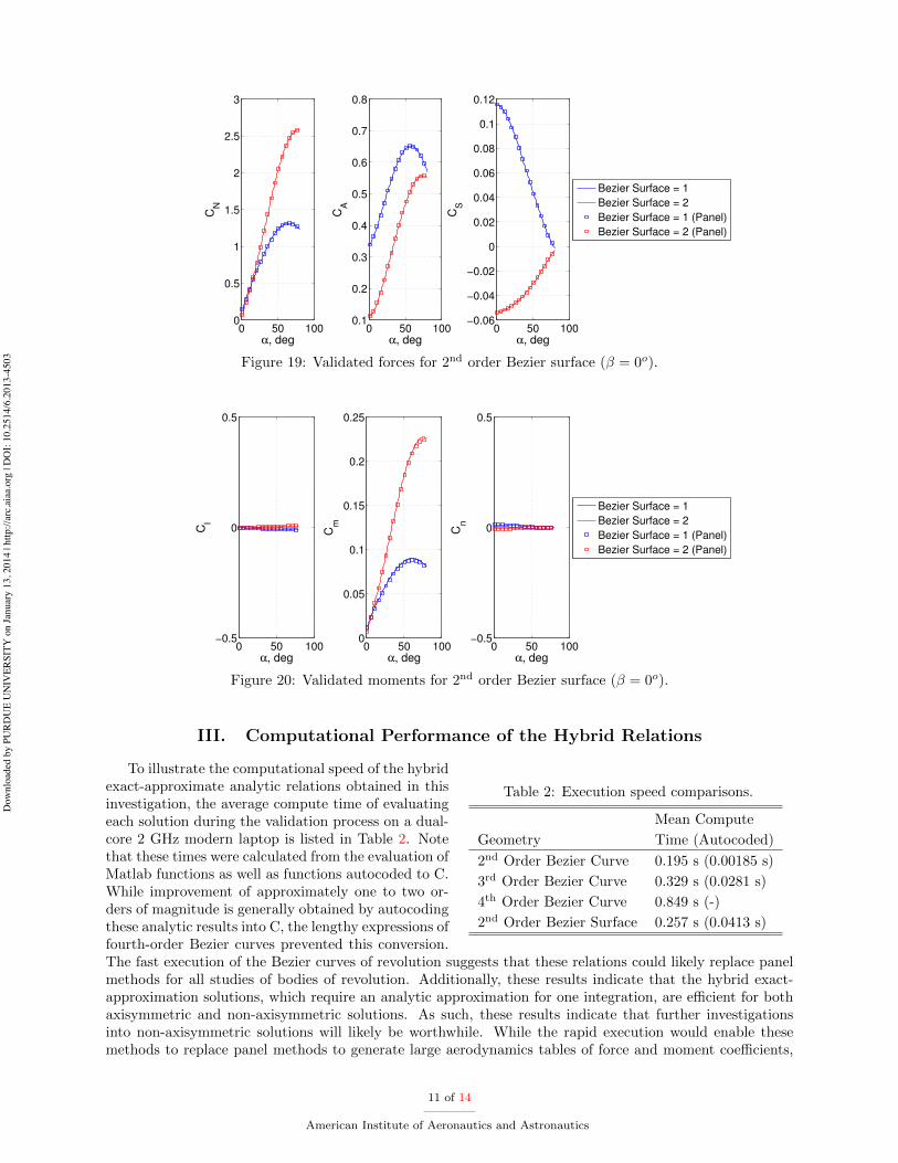
The non-axisymmetric Bezier surfaces described by the central control node lo-cations shown in Table 1 are validated using the panel method as shown in Figs. 19and 20. Note that this validation is conducted at a zero sideslip, and the analyticrelations currently do not account for nonzero sideslip angles. Due to the lack ofsymmetry, a side force, roll moment, and yaw moment is generated at zero sideslipangles. While these particular configurations would likely not be used for thesereasons (the asymmetry would likely only reside along the y-axis), the validated so-lutions illustrate that relatively complex non-axisymmetric analytic solutions can beconstructed. While excellent agreement exists in the force coe�cients, a minor discrepancy is observed inthe moment coe�cients. This illustrates the fully approximate nature of panel methods in which the shapeof the vehicle is approximated using small flat plates. For slender vehicles with complex shadow boundaries,the paneled integration demonstrates a slowly converging solution to the analytic result. This illustratesa challenge of using panel methods for high-performance, slender configurations. Since the mapping of ve-hicle shape accuracy to aerodynamic coe�cient accuracy is not known a priori, multiple paneled vehiclesof various accuracies are required until convergence of the aerodynamic relations is observed. Since thehybrid relations only require a quadrature rule along one direction, u, a highly accurate solution can beconstructed with a relatively few number of e�cient quadrature locations. In this work, a su�cient numberof Legendre-Gauss-Lobatto points (30) was chosen to ensure convergence of the numerical hybrid solutionsacross all geometries investigated.
10 of 14
American Institute of Aeronautics and Astronautics
Dow
nloa
ded
by P
URD
UE
UN
IVER
SITY
on
Janu
ary
13, 2
014
| http
://ar
c.ai
aa.o
rg |
DO
I: 10
.251
4/6.
2013
-450
3
0 50 1000
0.5
1
1.5
2
2.5
3
α, deg
CN
0 50 1000.1
0.2
0.3
0.4
0.5
0.6
0.7
0.8
α, degC
A
0 50 100−0.06
−0.04
−0.02
0
0.02
0.04
0.06
0.08
0.1
0.12
α, deg
CS
Bezier Surface = 1
Bezier Surface = 2
Bezier Surface = 1 (Panel)
Bezier Surface = 2 (Panel)
Figure 19: Validated forces for 2nd order Bezier surface (� = 0o).
0 50 100−0.5
0
0.5
α, deg
Cl
0 50 1000
0.05
0.1
0.15
0.2
0.25
α, deg
Cm
0 50 100−0.5
0
0.5
α, deg
Cn
Bezier Surface = 1
Bezier Surface = 2
Bezier Surface = 1 (Panel)
Bezier Surface = 2 (Panel)
Figure 20: Validated moments for 2nd order Bezier surface (� = 0o).
III. Computational Performance of the Hybrid Relations
Table 2: Execution speed comparisons.
Mean Compute
Geometry Time (Autocoded)
2nd Order Bezier Curve 0.195 s (0.00185 s)
3rd Order Bezier Curve 0.329 s (0.0281 s)
4th Order Bezier Curve 0.849 s (-)
2nd Order Bezier Surface 0.257 s (0.0413 s)
To illustrate the computational speed of the hybridexact-approximate analytic relations obtained in thisinvestigation, the average compute time of evaluatingeach solution during the validation process on a dual-core 2 GHz modern laptop is listed in Table 2. Notethat these times were calculated from the evaluation ofMatlab functions as well as functions autocoded to C.While improvement of approximately one to two or-ders of magnitude is generally obtained by autocodingthese analytic results into C, the lengthy expressions offourth-order Bezier curves prevented this conversion.The fast execution of the Bezier curves of revolution suggests that these relations could likely replace panelmethods for all studies of bodies of revolution. Additionally, these results indicate that the hybrid exact-approximation solutions, which require an analytic approximation for one integration, are e�cient for bothaxisymmetric and non-axisymmetric solutions. As such, these results indicate that further investigationsinto non-axisymmetric solutions will likely be worthwhile. While the rapid execution would enable thesemethods to replace panel methods to generate large aerodynamics tables of force and moment coe�cients,
11 of 14
American Institute of Aeronautics and Astronautics
Dow
nloa
ded
by P
URD
UE
UN
IVER
SITY
on
Janu
ary
13, 2
014
| http
://ar
c.ai
aa.o
rg |
DO
I: 10
.251
4/6.
2013
-450
3

the fast compute times indicate that these general expressions could also be e�ciently incorporated withinthe mathematically coupled, multidisciplinary design environment described in Section I.
IV. Future Work
Table 3: Common 2nd orderBezier curve of revolution ex-pressions.
Repeated Expression
b1xb2x(�1 + 2u+ 3u2 � 4u3)
2b21xu(1� 3u+ 2u2)
b1yb2y(3� 4u)u
b
22x(�1 + u
2)
b
21y(2� 6u+ 4u2)
(b22x + b
22y)u
2
2b1xb2x(1� 2u)u
2b1yb2y(1� 2u)u
b
21x(1� 2u)2
2b1y(�1 + u)
8b21yu3(�2b1y(�1 + u) + b2yu)
b1yb2yu(�1 + 2u)
This investigation demonstrated that e�cient hybrid exact-approximate analytic solutions can be constructed for general vehicle con-figurations. However, as illustrated in the enclosed database, the resultinganalytic expressions are lengthy, and many redundant calculated are em-bedded within the various relations. For example, investigation of theforce and moment solutions to the second-order Bezier curve of revolutionindicate that there are many common calculations such as those listed inTable 3. To improve execution speed, repeated calculations such as theseshould be calculated once, stored in memory, and referenced throughoutthe analytic expressions. As such, a symbolic optimization engine shouldbe created that is capable of analyzing the lengthy analytic expressions toidentify common terms and perform the corresponding symbolic substi-tutions. Note that this procedure is more challenging than may otherwisebe expected. As a simple example, if the term 2u2 is repeated throughoutan expression, then it is challenging to di↵erentiate this term with theterm 2u20. As a result, a detailed analysis of nearby characters must beperformed to ensure that the symbolic substitutions do not change theoverall calculation. After these substitutions are made, then it may bepossible to autocode higher-order solutions, including those of the fourth-order Bezier curve of revolution. To further enhance execution speed, adetailed quadrature analysis should be conducted to determine the appro-priate number of terms that may be best suited for each particular class of shapes. Note that since a highlye�cient quadrature scheme was used in this investigation, the benefits of this analysis will be secondary tothe aforementioned symbolic optimization.
While the e�ciency of existing analytic relations should be improved as much as possible, the limit ofnon-axisymmetric hybrid exact-approximate analytic solutions should be further investigated. As shown inSection II.B, limited solutions for 2nd order Bezier surfaces have been constructed for anchored edge controlnodes. However, when these anchored values are replaced with general constants, the current analyticintegration procedure fails. Since the constant anchored values are replaced with an unspecified constant,solutions to this more general representation of the Bezier surface should exist. However, the complexitiesassociated with the analytic integration process (e.g., real vs. complex domain analysis, assumptions on therelative arrangement of the node locations, etc.) have likely precluded the discovery of these more generalsolutions. Further investigation of these considerations may yield new solutions.
The major challenge associated with this investigation is that many expressions have no known integral,preventing the construction of analytic solutions. To avoid these integration challenges, the inverse aerody-namic problem should be studied in detail. In this potentially useful approach, the analytic aerodynamicswould be specified a priori, and the shape of the vehicle could be estimated via di↵erentiation of theseanalytic relations. Since di↵erentiation is a relatively straightforward process, this approach would not besubject to the integration challenges that are addressed in this investigation. As solutions to new config-urations are explored, special consideration should be given to emerging technologies such as morphing orflexible structures. For example, analytic relations for inflatable aerodynamic decelerators would enable thereal-time modeling of shape change during trajectory propagation. As such, these relations could be usedto improve the hypersonic modeling of passively flexible systems or to support targeting studies of activelycontrolled systems.
V. Summary
In this investigation, hybrid exact-approximate analytic aerodynamic relations are constructed for generalvehicle configurations based on Newtonian flow theory. These relations serve to expand on the prior analyticaerodynamic database that consisted of solutions to specific shapes such as spherical segments, conical
12 of 14
American Institute of Aeronautics and Astronautics
Dow
nloa
ded
by P
URD
UE
UN
IVER
SITY
on
Janu
ary
13, 2
014
| http
://ar
c.ai
aa.o
rg |
DO
I: 10
.251
4/6.
2013
-450
3

frustums, etc. Solutions to second-, third-, and fourth-order Bezier curves of revolution were constructedby performing the first surface integration analytically and subsequently incorporating the analytic shadowboundary into this result. Due to the complexity of the resulting expression, the final surface integrationis approximated analytically. Since the unshadowed surface limits have already been incorporated into thesolution, this final integration is performed in a manner that is independent of the orientation of the vehicle.As such, solutions in both force and moment coe�cients are created that account for both shadowed andunshadowed orientations. Since these analytic solutions are invariant, they can be incorporated into themathematically coupled multidisciplinary design environment as described in Section I. Additionally, themajority of axisymmetric vehicles of interest can likely be represented by these Bezier curves of revolution,and as a result, conceptual design studies of axisymmetric vehicles would likely not require the use ofpanel methods. To further expand the domain of hybrid exact-approximate analytic relations, solutions toconstrained second-order Bezier surfaces were also constructed for a zero sideslip. These solutions requirethe outer nodes to be anchored within the same plane, allowing the central node to be arbitrarily locatedto construct various non-axisymmetric geometries. Comparisons with an independently developed panelmethod validate the analytic solutions derived for both Bezier curves of revolution and Bezier surfaces.Average compute times of a fraction of a second illustrate the computational e�ciency of the hybrid exact-approximate analytic relations to support conceptual hypersonic design studies.
References
1Newton, I., Principia - Motte’s Translation Revised , University of California Press, 1946.2Anderson, J. D., Hypersonic and High Temperature Gas Dynamics, AIAA, 1989.3Rainey, R. W., “Working Charts for Rapid Prediction of Force and Pressure Coe�cients on Arbitrary Bodies of Revolution
by Use of Newtonian Concepts,” NASA TN D-176 , 1959.4Margolis, K., “Theoretical Evaluation of the Pressures, Forces, and Moments at Hypersonic Speeds Acting on Arbitrary
Bodies of Revolution Undergoing Separate and Combined Angle-of-Attack and Pitching Motions,” NASA TN D-652 , 1961.5Grimminger, G., Williams, E. P., and Young, G. B. W., “Lift on Inclined Bodies of Revolution in Hypersonic Flow,”
Journal of the Aeronautical Sciences, Vol. 17, No. 11, 1950.6Kinney, D. J., “Aero-Thermodynamics for Conceptual Design,” AIAA-2004-31-962, 42nd AIAA Aerospace Sciences
Meeting and Exhibit , Reno, NV, 5-8 Jan. 2004.7Bonner, E., Clever, W., and Dunn, K., “Aerodynamic Preliminary Analysis System II: Part I Theory,” NASA-CR-165627 ,
Apr. 1981.8Smyth, D. N. and Loo, H. C., “Analysis of Static Pressure Data from 1/12-scale Model of the YF-12A. Volume 3: The
MARK IVS Supersonic-Hypersonic Arbitrary Body Program, User’s Manual,” NASA-CR-151940 , Oct. 1981.9Cunningham, M., “Hypersonic Aerodynamics for an Entry Research Vehicle,” Journal of Spacecraft and Rockets, Vol. 24,
No. 2, 1987.10Theisinger, J. E. and Braun, R. D., “Multi-Objective Hypersonic Entry Aeroshell Shape Optimization,” Journal of
Spacecraft and Rockets, Vol. 46, No. 5, 2009.11Kinney, D. J., “Aerodynamic Shape Optimization of Hypersonic Vehicles,” AIAA 2006-239, 44th AIAA Aerospace Sci-
ences Meeting and Exhibit , Reno, NV, 9-12 Jan. 2006.12Mathematica, Ver. 7, Wolfram Research, Champaign, IL.13Grant, M. J. and Braun, R. D., “Analytic Hypersonic Aerodynamics for Conceptual Design of Entry Vehicles,” AIAA
2010-1212, 48th AIAA Aerospace Sciences Meeting Including the New Horizons Forum and Aerospace Exposition, Orlando,FL, 4-7 Jan. 2010.
14Grant, M. J., Rapid Simultaneous Hypersonic Aerodynamic and Trajectory Optimization for Conceptual Design, PhDThesis, Georgia Institute of Technology, School of Aerospace Engineering, May 2012.
15Grant, M. J. and Braun, R. D., “The Extension of Analytic Hypersonic Force Coe�cients for Conceptual Design Usingthe Divergence Theorem,” AIAA 2012-4580, AIAA Atmospheric Flight Mechanics Conference and Exhibit , Minneapolis, MN,13-16 Aug. 2012.
16Grant, M. J., “The Construction of Analytic Hypersonic Pitch Moment Coe�cients Using a Curl Transformation,” AIAA2013-0225, 51st AIAA Aerospace Sciences Meeting including the New Horizons Forum and Aerospace Exposition, Grapevine,TX, 7-10 Jan. 2013.
17Ho↵man, S. J. and Kaplan, D. I., “Human Exploration of Mars: The Reference Mission of the NASA Mars ExplorationStudy Team,” NASA Special Publication 6107 , July 1997.
18Drake, B. G., “Reference Mission Version 3.0 Addendum to the Human Exploration of Mars: The Reference Mission ofthe NASA Mars Exploration Study Team,” NASA Special Publication 6107-ADD , June 1998.
19Steinfeldt, B., Theisinger, J., Korzun, A., Clark, I., Grant, M., and Braun, R., “High Mass Mars Entry Descent andLanding Architecture Assessment,” AIAA 2009-6684, AIAA Space 2009 , Pasadena, CA, 14 - 17 Sept. 2009.
20Desai, P., Lyons, D., Tooley, J., and Kangas, J., “Entry, Descent, and Landing Operations Analysis for the StardustEntry Capsule,” Journal of Spacecraft and Rockets, Vol. 45, No. 6, 2008.
21Desai, P. and Lyons, D., “Entry, Descent, and Landing Operations Analysis for the Genesis Entry Capsule,” Journal ofSpacecraft and Rockets, Vol. 45, No. 1, 2008.
13 of 14
American Institute of Aeronautics and Astronautics
Dow
nloa
ded
by P
URD
UE
UN
IVER
SITY
on
Janu
ary
13, 2
014
| http
://ar
c.ai
aa.o
rg |
DO
I: 10
.251
4/6.
2013
-450
3

22Kinney, D. J. and Bowles, J. V., “Conceptual Design of a ‘SHARP’-CTV,” AIAA 2001-2887, 35th AIAA ThermophysicsConference, Anaheim, CA, 11-14 Jun. 2001.
23Grant, M. J., Clark, I. G., and Braun, R. D., “Rapid Design Space Exploration for Conceptual Design of HypersonicMissions,” AIAA Atmospheric Flight Mechanics Conference and Exhibit , Portland, OR, 8-11 Aug. 2011.
24Grant, M. J., Clark, I. G., and Braun, R. D., “Rapid Simultaneous Hypersonic Aerodynamic and Trajectory OptimizationUsing Variational Methods,” AIAA 2011-6640, AIAA Atmospheric Flight Mechanics Conference and Exhibit , Portland, OR,8-11 Aug. 2011.
25Rogers, D. F., An Introduction to NURBS: With Historical Perspective, Academic Press, London, 2001.
14 of 14
American Institute of Aeronautics and Astronautics
Dow
nloa
ded
by P
URD
UE
UN
IVER
SITY
on
Janu
ary
13, 2
014
| http
://ar
c.ai
aa.o
rg |
DO
I: 10
.251
4/6.
2013
-450
3