HYBRID ELECTRICAL VEHICLE - Weeblyajourneywithtime.weebly.com/uploads/6/7/3/3/6733268/hev.pdf ·...
55
http://ajourneywithtime.weebly.com/ “HYBRID ELECTRICAL VEHICLE” A Project Submitted in partial fulfillment for the Award of the degree of BACHELOR OF TECHONOLOGY IN MECHANICAL ENGINEERING Submitted by PRATEEK SINGH (1364540029) NAVNEET KUMAR (1364540023) DEEPENDRA CHOUDARY (1364540016) YOGESH KUMAR (1364540041) Under the Guidance of Mr. VISHNU KUNTAL IDEAL INSTITUTE OF MANAGEMENT & TECHNOLOGY, GHAZIABAD Dr. A. P. J. ABDUL KALAM TECHNICAL UNIVERSITY, LUCKNOW (2016-2017)
Transcript of HYBRID ELECTRICAL VEHICLE - Weeblyajourneywithtime.weebly.com/uploads/6/7/3/3/6733268/hev.pdf ·...
httpajourneywithtimeweeblycom
ldquoHYBRID ELECTRICAL VEHICLErdquo
A Project
Submitted in partial fulfillment for the
Award of the degree of
BACHELOR OF TECHONOLOGY
IN
MECHANICAL ENGINEERING
Submitted by
PRATEEK SINGH (1364540029)
NAVNEET KUMAR (1364540023)
DEEPENDRA CHOUDARY (1364540016)
YOGESH KUMAR (1364540041)
Under the Guidance of
Mr VISHNU KUNTAL
IDEAL INSTITUTE OF MANAGEMENT amp TECHNOLOGY GHAZIABAD
Dr A P J ABDUL KALAM TECHNICAL UNIVERSITY LUCKNOW
(2016-2017)
httpajourneywithtimeweeblycom
DECLARATION
We hereby declare that this submission is our own work to the best of our knowledge and belief
it contains no material previously or written by any other person nor material which to a
substantial extent has been accepted for the award of any degree or diploma of the university or
other institute of higher learning except where due acknowledgment and references has been
made in the text
NAME ROLL NUMBER SIGNATURE
PRATEEK SINGH (1364540029)
NAVNEET KUMAR (1364540023)
DEEPENDRA CHOUDARY (1364540016)
YOGESH KUMAR (1364540041)
Date-
httpajourneywithtimeweeblycom
IDEAL INSTITUTE OF MANAGEMENT amp TECHNOLOGY GHAZIABAD
Dr A P J ABDUL KALAM TECHNICAL UNIVERSITY LUCKNOW
(An ISO 90012008 Certified Institution)
Phone - 0120-2767816 0120-2767818 Fax - 0120-2767352
Email- infoidealinstituteacin Website- wwwidealinstituteacin
CERTIFICATE
This is to certify that project report entitled ldquoHYBRID ELECTRICAL VEHICLErdquo which is
being submitted by Prateek Singh (Roll No 1364540029) Navneet Kumar (Roll No
1364540023 ) Deependra Choudhary (Roll No 1364540016) Yogesh Kumar (Roll No
1364540041) in partial fulfilment for the requirement for the award of the degree of Bachelor of
Technology in department of Mechanical Engineering of Ideal Institute of Management and
Technology Ghaziabad under Dr A P J Abdul Kalam Technical University Lucknow They
have worked under the guidance of Mr VISHNU KUNTAL (Asst Professor Department of
Mechanical Engineering IIMT GZB) and have fulfilled the requirement for the submission of
the project The matter embodied in this thesis is original and has not been submitted for the
award of any other degree
Signature of Supervisor Signature of HOD Signature of External
Examiner
Mr VISHNU KUNTAL Mr M K PODDAR
Assistant Professor Assistant Professor
Dept of Mech Engg Dept of Mech Engg
Date-
ii
httpajourneywithtimeweeblycom
ACKNOWLEDGEMENT
First of all I would like to thank the almighty God for listening my prayers and giving me
strength to complete the dissertation work
I would like to express a deep sense of gratitude and thanks profusely to Mr VISHNU
KUNTAL Assistant Professor Department of Mechanical Engineering Ideal Institute of
Management and Technology Ghaziabad (UP) my guides and mentors without the wise
counsel and able guidance it would have been impossible to complete the dissertation in this
manner
I am also grateful to Ideal Institute of Management and Technology Ghaziabad especially
Department of Mechanical Engineering for extending all facilities and cooperation to me for
carrying out this work I shall be failing in my duty if I donrsquot acknowledge the support received
from Mr VISHNU KUNTAL Department of Mechanical Engineering IIMT Ghaziabad (UP)
in order to complete my work
I must also express my deep regards and thanks to my parents for supporting and boosting my
morale so that I can overcome my hard times
I finally pray that Almighty fulfils the aspirations of all the people who have been a part of this
journey and those who will be a part of future journeys
NAME ROLL NUMBER SIGNATURE
PRATEEK SINGH (1364540029)
NAVNEET KUMAR (1364540023)
DEEPENDRA CHOUDARY (1364540016)
YOGESH KUMAR (1364540041)
Date-
iii
httpajourneywithtimeweeblycom
ABSTRACT
In an era where energy conservation has become the latest topic of discussion not only among
the erudite but also among the ordinary responsible denizens fuel efficiency along with
minimum pollution has become the benchmark for any new automobile and in the same context
ldquoHybrid Carsrdquo come as the latest addition
By the name itself it can be inferred that a hybrid car is an improvisation to the traditional
gasoline engine run car combined with the power of an electric motor
The project on the above topic intends to bring to notice the concepts associated with the hybrid
technology through the following topics components and constituents need efficiency
performance etc
iv
httpajourneywithtimeweeblycom
NOMENCLATURE
Symbol Description
D Dia Of Blade
A Cross-section area of Blade
D Dia Of Shaft
KE Kinetic Energy of Air
M Mass of Air
V Velocity of Air
P Pressure of Air
B Thickness of Blades
kW Kilo watt
kmhr Kilometer per Hour
G Spring Action to Provide Motion
I Electrical Energy Out
F Force exerted on the pillar piston
A Permanent Magnets to provide Induced EMF
B Rod to connect wheel
C Rubber Spring
E Shocker Rod
ms Meter per second
httpajourneywithtimeweeblycom
V
c
Speed of light
Rpm Revolution per minute
PV Cells Photovolatic cells
Ρ Density of Air
WECS
HEV
Wind Energy Conversion System
Hybrid electrical vehicle
vi
httpajourneywithtimeweeblycom
TABLE OF CONTENTS
Page No
Declaration i
Certificate ii
Acknowledgement iii
Abstract iv
Nomenclature v-vi
List of Contents vii-viii
List of Figure ix
CHAPTER 1 INTRODUCTION 2
11 What makes it a Hybrid 3
12 Hybrid Components 4
13 Parts of Electric Motor 5
14 Hybrid Generate Unit 6
15 Hybrid System Block Diagram 7
16 Hybrid Generate Station 7
CHAPTER 2 LITERATURE SURVEY 9
21 Literature survey of the HEV 10
22 Project Objectives 12
CHAPTER 3 DESIGN AND CONSTRUCTION 13
31 WIND ENERGY 14
311 Conversion Principle Block Diagram 16
312 Nature of the Wind 17
313 Wind Power 17
314 Pressure and Velocity Diagram 19
315 Maximum Power 21
316 Wind Energy Conversion 21
317 Environmental Aspects 22
32 SOLAR ENERGY 23
321 Direct method 23
322 Photovolatic Method 24
Vii
httpajourneywithtimeweeblycom
33 SOUND ENERGY 27
331 Transformation of Sound Energy 27
332 Sound 29
333 Microphones 30
334 Microphones reverse of loudspeaker 30
335 How microphones works 31
336 Types of microphones 32
34 SHOCK ABSORBER 34
341 Regenerative shock absorber 34
342 Electricity generation 36
343 Shock absorber 37
344 Explanation 38
345 Description 39
346 Applications 39
347 Vehicle suspension 39
348 Structure 40
349 Types of shock absorber 40
35 Assembly of HEV Model 42
CHAPTER 4 COST ANALYSIS 47
CONCLUSIONS 49
FURTHER DEVELOPMENTS 50
REFRENCES 51
viii
httpajourneywithtimeweeblycom
ix
LIST OF FIGURE
Figure Topic Page No
1 Hybrid vehicle 2 11
2 Electric vehicle 3 14
3 Block diagram of Hybrid system 7 18
4 Wind block diagram 16 23
5 Pressure velocity diagram 19 28
6 Working diagram of solar panel 24 34
7 Working principal of microphone 30
8 Microphone 31
44
9 Regenerative shock absorber 33 50
91 Design 1 34 50
92 Design 2 35 51
10 Electricity shock absorber 36 52
11 Shock absorber 37 53
12 Shock absorber with internal absorber 38 55
13 Shocker or Spring 39 56
httpajourneywithtimeweeblycom
CHAPTER- 1
INTRODUCTION
1 | P a g e
httpajourneywithtimeweeblycom
CHAPTER 1 INTRODUCTION
Energy is a requirement that is endlessly and exhaustingly utilized the world over With the
increase in the rate of various developmental activities around the world the energy being
consumed is also increasing with the result that conventional energy resources are fast getting
depleted and even reserves are proving less than sufficient to satisfy the growing energy demand
As a result consumers around the world have to bear the brunt of increasing power cuts and
power costs Hence for the future power independence is fast becoming a vital requirement The
concept design therefore formulates a system which provides internally generated energy for
homes and also integrates a sub system into the household such that the dependence on the
electricity
Figure 1
11 What makes it a Hybrid
Any vehicle is hybrid when it combines two or more sources of power In fact
2 | P a g e
httpajourneywithtimeweeblycom
Many people have probably owned a hybrid vehicle at some point For example a mo-ped (a
motorized pedal bike) is a type of hybrid because it combines the power of a gasoline engine
with the pedal power of its rider
Hybrid vehicles are all around us Most of the locomotives we see pulling trains are diesel-
electric hybrids Cities like Seattle have diesel-electric buses -- these can draw electric power
from overhead wires or run on diesel when they are away from the wires Giant mining trucks
are often diesel-electric hybrids Submarines are also hybrid vehicles -- some are nuclear-electric
and some are diesel-electric Any vehicle that combines two or more sources of power that can
directly or indirectly provide propulsion power is a hybrid
Figure 2 below shows an electric car which has a set of batteries that provides electricity to an
electric motor The motor turns a transmission and the transmission turns the wheels
Figure 2
13 | P a g e
httpajourneywithtimeweeblycom
12 HYBRID COMPONENT
Hybrid cars contain the following parts
Electric motor - The electric motor on a hybrid car is very sophisticated Advanced
electronics allow it to act as a motor as well as a generator For example when it needs
to it can draw energy from the batteries to accelerate the car But acting as a generator it
can slow the car down and return energy to the batteries
Generator - The generator is similar to an electric motor but it acts only to produce
electrical power It is used mostly on series hybrids
Batteries - The batteries in a hybrid car are the energy storage device for the electric
motor Unlike the gasoline in the fuel tank which can only power the gasoline engine the
electric motor on a hybrid car can put energy into the batteries as well as draw energy
from them
Transmission - The transmission on a hybrid car performs the same basic function as the
transmission on a conventional car Some hybrids like the Honda Insight have
conventional transmissions Others like the Toyota Prius have radically different ones
which well talk about later
13 PARTS OF AN ELECTRIC MOTOR
Lets start by looking at the overall plan of a simple two-pole DC electric motor A simple motor
has six parts as shown in the diagram below
Armature or rotor
Commutator
Brushes
Axle
Field magnet
DC power supply of some sort
Parts of an electric motor
2
4 | P a g e
httpajourneywithtimeweeblycom
An electric motor is all about magnets and magnetism A motor uses magnets to create motion If
you have ever played with magnets you know about the fundamental law of all magnets
Opposites attract and likes repel So if you have two bar magnets with their ends marked north
and south then the north end of one magnet will attract the south end of the other On the other
hand the north end of one magnet will repel the north end of the other (and similarly south will
repel south) Inside an electric motor these attracting and repelling forces create rotational
motion
In the diagram we can see two magnets in the motor The armature (or rotor) is an electromagnet
while the field magnet is a permanent magnet (the field magnet could be an electromagnet as
well but in most small motors it isnt in order to save power)
14 HYBRID GENERATING UNIT
The generating unit for the proposed design utilizes a hybrid power source as a means of
powering the household loads The hybrid power source combines wind and solar energy to
service the household requirements
Hybrid system for home is a combined system of wind and solar power generation system Aero
turbines convert wind energy into rotary mechanical energy A mechanical interface consisting
of a step-up gear and a suitable coupling transmits the energy to an electrical generator The
output of this generator is connected to the Battery or system grid The battery is connected to
the inverter The inverter is used to convert DC voltages to AC voltages The load draws current
from the inverter
The apparatus involved for the windmill section are
Generator
Main shaft with Leafs
Gear Wheel Arrangement
Wind power ratings can be divided into three convenient grouping small to 1kW
medium to 50 kW and large 200 kW to megawatt frame size
15 | P a g e
httpajourneywithtimeweeblycom
Solar energy implies the energy that reaches the earth from the sun It provides daylight makes
the earth hot and is the source of energy for plants to grow Solar energy is also put to two types
of use to help our lives directly solar heating and solar electricity Solar electricity is the
technology of converting sunlight directly in to electricity It is based on photo-voltaic or solar
modules which are very reliable and do not require any fuel or servicing Solar electric systems
are suitable for plenty of sun and are ideal when there is no main electricity
15 HYBRID SYSTEM BLOCK DIAGRAM
Figure3
16 HYBRID GENERATING STATION
Hybrid system for home is a combined system of wind and solar power generation system Aero
turbines convert wind energy into rotary mechanical energy A mechanical interface consisting
of a step-up gear and a suitable coupling transmits the energy to an electrical generator The
output of this generator is connected to the Battery or system grid The battery is connected to
16 | P a g e
SOUND
ENERGY
WIND
POWER
CHANGER
CONTROLLER
SOLAR POWER
SHOCK
ABSORBER
LEAD ACID BATTERY
POWER CONTROLEER
DC MOTOR
DC MOTOR
httpajourneywithtimeweeblycom
the inverter The inverter is used to convert DC voltages to AC voltages The load is drawn
current from the inverter
Wind power ratings can be divided into three convenient grouping small to 1kW medium to 50
kW and large 200 kW to megawatt frame size
Solar energy means all the energy that reaches the earth from the sun It provides
daylight makes the earth hot and is the source of energy for plants to grow Solar
energy is also put to two types of use to help our lives directly solar heating and
solar electricity
Solar electricity is the technology of converting sunlight directly into electricity It
is based on photo-voltaic or solar modules which are very reliable and do not
require any fuel or servicing Solar electric systems are suitable for plenty of sun
and are ideal when there is no main electricity
7 | P a g e
httpajourneywithtimeweeblycom
CHAPTER - 2
LITERATURE SURVEY
8 | P a g e
httpajourneywithtimeweeblycom
CHAPTER 2 LITERATURE SURVEY
21 Literature review of Hybrid Electric Vehicle
1 Rushikesh Trushar Soni (2015) [1] investigated on hybrid electric vehicle and he has been
fond that the transmission of power using freewheels and chain wheels are very cheap and
reliable One disadvantage is that driving on electric power is not a good option for a long
distance travel Though this combined power train system can become much useful in more stop
and go traffic situations With the use of this power train system the overall fuel consumption
and fuel economy is improved Such vehicle would run on fuel but would use its electric motor
to boost the power when needed The cost of HEVs is a little more than the conventional cars but
they more efficient and the exhaust emissions are less
2 Parag Kulkarni (2015) [2] demonstrates the growing need for sustainable transportation in the
World and the role of HEVs as a possible solution Through technology review and comparative
analysis it shows that HEVs can significantly reduce harmful emissions of gases This paper
summarizes the key initiatives and features of Hybrid Electric Car adapted by the world to
encourage the purchase of fuel-efficient vehicles particularly hybrid electric vehiclesIt also
gives brief information about hybrid electric vehicles their categories and types according to
different parameters
3 T Vignesh et al(2017) [3] investigated Energy and environmental issues are among the most
important problems of public concern Wind and solar energy may be one of the alternative
solutions to overcome energy shortage and to reduce greenhouse gaseous emission Using
electric cars in cities can significantly improve the air quality there The basic principle of solar
based electric vehicle is to use energy that is stored in a battery to drive the motor and it moves
the vehicle in forward or reverse direction The DC voltage from the PV panel is then boosted up
using a boost DC-DC converter and then an inverter where DC power is converted to AC power
as well as AC power is generated by using wind turbines ultimately runs the Brushless DC
motor which is used as the drive motor for the vehicle application This paper focuses on the
design and implementation of the various components namely solar panel wind turbine charge
controller battery DC-DC boost converter DC-AC power converter (inverter circuit) arduino
processor and BLDC motor for the vehicle application This idea in future may help protect our
9 | P a g e
httpajourneywithtimeweeblycom
fuels from getting extinguished This study proposed an improvement of the energy management
system of a hybrid electric vehicle using using Renewable Energy Sources Hybrid power
generation system is good and effective solution for power generation than conventional energy
resources It has greater efficiency It can provide to remote places where government is unable
to reach So that the power can be utilize where it generated so that it will reduce the
transmission losses and cost Cost reduction can be done by increasing the production of the
equipment People should motivate to use the non-conventional energy resources It is highly
safe for the environment as it doesnrsquot produce any emission and harmful waste product like
conventional energy resources
In Germany being able to use a car is one element of individual freedom and is a cornerstone of
individual mobility 82 (2008) of all German households possess a car and in just over a third
of these households two or more cars are available Despite the already high degree of car
availability in the past the motorization has even further increased in recent years (Follmer et al
2010) In the new millennium the high dependence of individual mobility on private cars led to a
discussion of alternatives to the internal combustion engine initiated particular by significantly
increasing oil prices Worldwide many governments and interest groups moved the issue of
sustainable mobility in the foreground (Greenpeace 2010 Kendall 2008) Hybrid and electric
vehicles (EV) are seen as an important part of a technology portfolio targeted at reducing
greenhouse gas emissions as well as the dependence on oil by funding the expansion of
renewable energies developing new mobility concept eg for public transport or supporting
technological developments (Greenpeace 2010 Kendall 2008) The electrification of the
drivetrian could lead to a sustainable technology path which benefits the consumer by lower and
less volatile (electricity) prices for mobility (Schill 2010a c) This discussion is encouraged by
the fact that electric mobility is benefitting from high oil prices (Conrady 2012 Dijk et al 2012)
The rise of interest in the topic electric mobility may be particularly well traced by looking to the
internet This can be done by considering first the number of search inquiries of internet users
over a time span and second by analyzing the number of hits displayed by search engines over a
period for a specific topic We have first investigated different frequently used keywords with
Google Insight for Search (Fig 1) There are three search inquiries related to electric mobility
that were most often searched in Google electric mobility electric car and electric vehicle
10 | P a g e
httpajourneywithtimeweeblycom
After that we have investigated the number of searches in the period from the beginning of 2004
till the end of June 2012 It turns out that especially the term lsquoelectric carrsquo was asked with peaks
in 2006 and 2008
22 PROJECT OBJECTIVES
The title of project work is ldquoHYBRID ELECTRIC VEHICLE (HEV)rdquo
To meet increasing fuel economy and emissions legislation the automotive industry will need to
undergo drastic changes in vehicle and engine designs Unlike conventional vehicles on the road
today hybrid electric vehicles (HEV) are designed with a smaller engine and an on-board energy
storage system The smaller engine allows the vehicle to achieve better fuel economy and fewer
emissions The efficiency benefits of diesel engines over gasoline engines make the diesel engine
a strong contender for further improving fuel economy The integration of diesel-engine
technology into a hybrid electric vehicle configuration is one of the most promising ways to
comply with fuel-economy and emissions legislation Using simulation software it is possible to
quickly and easily optimize the engine and vehicle prior to investing time and money into testing
components and building prototypes The ability to integrate an advanced engine simulation
software output and an HEV simulation for the prediction of engine alterations on overall vehicle
performance is a critical tool for the success of meeting vehicle emissions and fuel economy
goals
The objectives of the present work are
Study on renewable energy sources on the basis of performance economy and
applications
Design and construct a working unit model of hybrid electric vehicle using renewable
energy sources
Cost analysis of HEV using renewable energy sources unit
11 | P a g e
httpajourneywithtimeweeblycom
CHAPTER ndash 3
DESIGN AND CONSTRUCTION
12 | P a g e
httpajourneywithtimeweeblycom
CHAPTER 3 DESIGN AND CONSTRUCTION
31 WIND ENERGY
Wind result from air in motion Air in motion arises from a pressure gradient On a global basis
one primary forcing function causing surface winds from the poles toward the equator is
convective circulation Solar radiation heats the air near the equator and this low density heated
air is buoyed up At the surface it is displaced by cooler more dense higher pressure air flowing
from the poles In the upper atmosphere near the equator the air thus tend to flow back toward
the poles and away from the equator The net result is a global convective circulation with
surface wins from north to south in the northern hemisphere
It is clear from the above over simplified model that the wind is basically caused by the solar
energy irradiating the earth This is why wind utilization is considered a part of solar
technologyIt actuality the wind is much more complex The above model ignores the earth
rotation which causes a coriolis force resulting in an easterly wind velocity component in the
northern hemisphere There is the further complication of boundary layer frictional effects
between the moving air and the earth rough surface Mountains trees buildings and similar
obstructions impair stream line air flow Turbulence results and the wind velocity in a horizontal
direction markedly increase with altitude near the surface Local winds are caused by two
mechanisms The first is differential hating of land and water Solar isolation during the day is
readily converted to sensible energy of the land surface but is partly absorbed in layers below the
water surface and partly consume in evaporating some of that water The land mass becomes
hotter than the water which causes the air above the land to heat up and become warmer than
the air above water The warmer lighter air above the land rises and the cooler heavier air
above the water moves into replace it This is the mechanism of shore breezes At night the
direction of the breezes is reversed because the land mass cools to the sky more rapidly than the
water assuming a sky The second mechanism of local winds is caused by hills and mountain
sides The air above the slopes heats up during the day and cools down at night more rapidly
than the air above the low lands This causes heated air the day to rise along the slopes and
relatively cool heavy air to flow down at night Wind turbines produce rotational motion wind
energy is readily converted into electrical energy by connecting the turbine to an electric
13 | P a g e
httpajourneywithtimeweeblycom
generator The combination of wind turbine and generator is sometimes referred as an aero
generator A step-up transmission is usually required to match the relatively slow speed of the
wind rotor to the higher speed of an electric generator
In India the interest in the windmills was shown in the last fifties and early sixties A part from
importing a few from outside new designs was also developed but it was not sustained It is
only in the last few years that development work is going on in many institutions An important
reason for this lack of interest in wind energy must be that wind in India area relatively low and
vary appreciably with the seasons Data quoted by some scientists that for India wind speed
value lies between 5 kmhr to 15-20 kmhr These low and seasonal winds imply a high cost of
exploitation of wind energy Calculations based on the performance of a typical windmill have
indicated that a unit of energy derived from a windmill will be at least several times more
expensive than energy derivable from electric distribution lines at the standard rates provided
such electrical energy is at all available at the windmill site
The above argument is not fully applicable in rural areas for several reasons First electric power
is not and will not be available in many such areas due to the high cost of generation and
distribution to small dispersed users Secondly there is possibility of reducing the cost of the
windmills by suitable design Lastly on small scales the total first cost for serving a felt need
and low maintenance costs are more important than the unit cost of energy
The last point is illustrated easily dry cells provide energy at the astronomical cost of about
Rs300 per kWh and yet they are in common use in both rural and urban areas Wind energy
offers another source for pumping as well as electric power generation India has potential of
over 20000 MW for power generation and ranks as one of the promising countries for tapping
this source The cost of power generation from wind farms has now become lower than diesel
power and comparable to thermal power in several areas of our country especially near the
coasts Wind power projects of aggregate capacity of 8 MW including 7 wind farms projects of
capacity 685 MW have been established in different parts of the country of which 3 MW
capacity has been completed in 1989 by DNES Wind farms are operating successfully and have
already fed over 150 lakes units of electricity to the respective state grids Over 25 MW of
additional power capacity from wind is under implementation Under demonstration
14| P a g e
httpajourneywithtimeweeblycom
Programmer 271 wind pumps have been installed up to February 1989 Sixty small wind battery
charges of capacities 300 watts to 4 kW are under installation Likewise to stand-alone wind
electric generators of 10 to 25 kW are under installation
311 CONVERSION PRINCIPLES BLOCK DIAGRAM
Figure 4
A wind turbine is a machine that converts wind energy into electricity The generators are
connected to battery charging circuits and finally to large utility grids In windmills the
wind passes through the airfoil section of the blades and the lift produced generates a
torque which is then transformed to electricity in the generator The conversion of the
wind energy into the mechanical energy of the turbine and then finally to electricity As
the output of the wind turbine is dependent on the availability of the winds it is
intermittent and undependable They can however be used along with conventional
generators in a large grid and can reduce the loads of these generators when they are
generating The other option is to use storage devices like batteries and then discharge the
electricity uniformly
312 NATURE OF THE WIND
The circulation of air in the atmosphere is caused by the non-uniform heating of the earth surface
by the sun The air immediately above a warm area expands it is forced upwards by cool
denser air which flows in from surrounding areas causing a wind The nature of the terrain the
degree of cloud cover and the angle of the sun in the sky are all factors which influence this
process In general during the day the air above the land mass tends to heat up more rapidly
15 | P a g e
httpajourneywithtimeweeblycom
than the air over water In coastal regions this manifests itself in a strong onshore wind At
night the process is reversed because the air cools down more rapidly over the land and the
breeze therefore blows off shore the main planetary winds are caused in much the same way
Cool surface air sweeps down from the poles forcing the warm air over the topics to rise But the
direction of these massive air movements is affected by the rotation of the earth and the net
pressure areas in the countries-clockwise circulation of air around low pressure areas in the
northern hemisphere and clockwise circulation in the southern hemisphere The strength and
direction of these planetary winds change with the seasons as the solar input varies
Despite the winds intermittent nature wind patterns at any particular site remains remarkably
constant year by year Average wind speeds are greater in hilly and coastal areas than they are
well inland The winds also tend to blow more consistently and with greater strength over the
surface of the water where there is a less surface drag
Wind speeds increase with height They have traditionally been measured at a standard height
of ten meters where they are found to be 20-25 greater than close to the surface At a height of
60 m they may be 30-60 higher because of the reduction in the drag effect of the earth surface
313 WIND POWER
The power in the wind can be computed by using the concept of kinetics The wind will works
on the principle of converting kinetic energy of the wind to mechanical energy We know that
power is equal to energy per unit time The energy available is the kinetic energy of the wind
The kinetic energy of any particle is equal to one half its mass times the square of its velocity or
12m V2 The amount of air passing in unit time through an area A with velocity V is AV and
its mass m is equal to its volume multiplied by its density of air o
m=AV
( m is the mass of air transverse the area A swept by the rotating blades of a wind mill
type generator)
Substituting this value of the mass in the expression for the kinetic energy we obtain
kinetic energy = 12 AVV2 watts
=12 AV3 watts
16 | P a g e
httpajourneywithtimeweeblycom
Equation tells us that the maximum wind available the actual amount will be somewhat less
because all the available energy is not extractable-is proportional to the cube of the wind speed
It is thus evident that small increase in wind speed can have a marked effect on the power in the
wind
Equation also tells us that the power available is proportional to air density 1225 kgm3 at sea
level) It may vary 10-15 percent during the year because of pressure and temperature change It
changes negligibly with water content Equation also tells us that the wind power is proportional
to the intercept area Thus an aero turbine with a large swept area has higher power than a
smaller area machine but there are added implications Since the area is normally circular of
diameter D in horizontal axis aero turbines then A = 4 D2 (sqm) which when put in equation
gives
Available wind power P = frac12 4 D2V
3 watts
= 18 D2V
3
314 PRESSURE AND VELOCITY GRAPH
Figure 5
17 | P a g e
httpajourneywithtimeweeblycom
The power extracted by the rotor is equal to the product of the wind speed as it passes through
the rotor (ie Vr) and the pressure drop p in order to maximize the rotor power it would
therefore be desirable to have both wind speed and pressure drop as large as possible However
as V is increased for a given value of the free wind speed (and air density) increases at first
passes through a maximum and the decreases Hence for the specified free-wind speed there is
a maximum value of the rotor power
The fraction of the free flow wind power that can be extracted by a rotor is called the power-
coefficient thus
Power of wind rotor
Power coefficient =
Power available in the wind
Where power available is calculated from the air density rotor diameter and free wind speed as
shown above The maximum theoretical power coefficient is equal to 1627 or 0593 This
value cannot be exceeded by a rotor in a free-flow wind-stream
315 MAXIMUM POWER
The total power cannot be converted to mechanical power Consider a horizontal-axis propeller-
type windmill henceforth to be called a wind turbine which is the most common type used
today Assume that the wheel of such a turbine has thickness b Let pi and Vi are the wind
pressure and velocity at the upstream of the turbine Ve is less than Vi because the turbine
extracts kinetic energy
18 | P a g e
Considering the incoming air between I and a as a thermodynamic system and
assuming that the air density remains constant (since changes in pressure and
temperature are very small compared to ambient) that the potential energy is zero and
no heat or work are added or removed between i and a the general energy equation
reduces to the kinetic and flow energy-terms only
316 WIND ENERGY CONVERSION
Traditional windmills were used extensively in the middle Ages to mill grain and lift
water for land drainage and watering cattle Wind energy converters are still used for
these purposes today in some parts of the world but the main focus of attention now
lies with their use to generate electricity There is also growing interest in generating
heat from the wind for space and water heating and for glass-houses but the potential
market is much smaller than for electricity generation
The term ldquowind millrdquo is still widely used to describe wind energy conversion systems
however it is hardly adopt Description any more Modern wind energy conversion
systems are more correctly referred to as lsquoWECS aero generations lsquowind turbine
generators or simply lsquowind turbines The fact that the wind is variable and intermittent
source of energy is immaterial of some applications such as pumping water for land
drainage ndash provided of course that there is a broad match between the energy supplied
over any critical period and the energy required If the wind blows the job gets done
if it does not the job waits
However for many of the uses to which electricity is put the interruption of supply
may be highly inconvenient Operators or users of wind turbines must ensure that there
is some form of back-up to cover periods when there is insufficient (or too much) wind
available For small producers back-up can take the form of
(i) Battery storage
(ii) Connection with the local electricity distribution system or
For utilities responsible for public supply the integration of medium ndash sized and
large wind turbines into their distribution network could require some additional plant
which is capable of responding quickly to meet fluctuating demand
19 | P a g e
317 ENVIRONMENTAL ASPECTS
Wind turbines are not without environmental impact and their operation is not
entirely risk-free Following are the main effects due to a wind turbine
(i) Electromagnetic interference Interference with TV and other electromagnetic
communication systems is a possibility with wind turbines as it is with other tall
structures TV interference is most likely in areas where there is a weak signal because
of the distance from the transmitter where existing reception is none too good due to
the surrounding hills and where the wind turbine is exposed in good position to receive
and scatter the signals Dispensing with aerials and sending TV signals by cable in
areas that would otherwise be affected can overcome interference
(ii) Noise The noise produced by wind farms falls into two categories The first type
is a mechanical noise from the gearbox generating equipment and linkages and the
second type of aerodynamic in nature produced by the movement of the turbine blades
One component of the latter is the broad band noise which ranges up to several kilo
hertz and the other is a low frequency noise of 15-20 Hz Revolving blades generate
noise which can be heard in the immediate vicinity of the installation but noise does
not travel too far
(iii) Visual Effects Megawatts power generating wind turbines are massive structures
which would be quite visible over a wide area in some locations Variety
characteristics such as color pattern shape rotational speed and reflectance of blade
materials can be adjusted to modify the visual effects of wind turbines including the
land scape in which they are installed
32 SOLAR ENERGY
Solar energy is radiant light and heat from the Sun that is harnessed using a range of
ever-evolving technologies such as solar heating photovoltaics solar thermal energy
solar architecture molten salt power plants and artificial photosynthesis
It is an important source of renewable energy and its technologies are broadly
characterized as either passive solar or active solar depending on how they capture and
distribute solar energy or convert it into solar power Active solar techniques include
the use of photovoltaic systems concentrated solar power and solar water heating to
harness the energy Passive solar techniques include orienting a building to the Sun
20 | P a g e
selecting materials with favorable thermal mass or light-dispersing properties and
designing spaces that naturally circulate air
321 DIRECT METHOD OF UTILIZATION OF SOLAR ENERGY
The most useful way of harnessing solar energy is by directly converting it into
electricity by means of solar photo-voltaic cells Sunshine is incident on Solar cells in
this system of energy Conversion that is direct conversion of solar radiation into
electricity In the stage of conversion into thermodynamic from is absent The photo-
voltaic effect is defined as the generation of an electromotive force as a result of the
absorption of ionizing radiation Energy conversion devices which are used to convert
sunlight to electricity by use of the photo-voltaic effect are called solar cells
Figure 6
In recent years photo-voltaic power generation has been receiving considerable
attention as one of the more promising energy alternatives The reason for this rising
interest lie in PVrsquos direct conversion of sunlight to electricity the non-polluting nature
of the PV widespread are of PV generation has been hampered by economic factors
Here to force the low cost of conventional energy sunlight has obviated the
development of a broad-based PV technology At the present time PV generation can
be justified only for special situations mostly for remote sites where utility lines on
other conventional means of furnishing energy may be prohibitively expensive and is
21 | P a g e
one of the most attractive non-conventional energy sources of proven reliability from
the micro to the Mega-watt level
Like other energy system this system also has some disadvantages
(1) Distributed nature of solar energy
(2) Absence of energy storage
(3) Relatively high capital cost
322 PHOTOVOLTAIC PRINCIPLES
The photo-voltaic effect can be observed in nature in a variety of materials that have
shown that the best performance in sunlight is the semiconductors as stated above
When photons from the sun are absorbed in a semiconductor that create free electrons
with higher energies than the created there must be an electric field to induce these
higher energy electrons to flow out of the semi-conductor to do useful work A
junction of materials which have different electrical properties provides the electric
field in most solar cells
To obtain a useful power output from photon interaction in a semiconductor three
processes are required
1) The photon has to be absorbed in the active part of the material and
result in electrons being excited to a higher energy potential
2) The electron hole charge carriers created by the absorption must be
physically separated and moved to the edge of the cell
3) The charge carriers must be removed from the cell and delivered to
useful load before they lose extra potential
For completing the above processes a solar cell consists of-
(a) Semi-conductor in which electron hole pairs are created by
absorption of incident solar radiation
(b) Region containing a drift field for charge separation
(c) Charge collecting fronts and back electrodes
22 | P a g e
The photo-voltaic effect can be described easily for p-n junction in a semi-conductor
In an intrinsic semi-conductor such as silicon each one of the four valence electrons of
the material atom is tied in a chemical bond and there are no free electrons at absolute
zero If a piece of such a material is doped on one side by a five valance electron
material such as arsenic or phosphorus there will be an excess of electrons in that side
becoming an n-type semi-conductor
The excess electrons will be practically free to move in the semi-conductor lattice
When a three valence electron material such as boron dopes the other side of the same
piece there will be deficiency of electrons leading to a p-type semi-conductor This
deficiency is expressed in terms of excess of holes free to move in the lattice Such a
piece of semi-conductor with one side of the p-type and the other of the n-type is
called p-n junction In this junction after the protons are absorbed the free electrons of
the n-side will tends to flow to the p-side and the holes of the p-side will tend to flow
to the n-region to compensate for their respective deficiencies This diffusion will
create an electric field from the n-region to the p-region This field will increase until it
reaches equilibrium for V the sum of the diffusion potentials for holes and electrons
33 SOUND ENERGY
In physics energy (from the Greek ἐνέργεια - energeia activity operation from
ἐνεργός - energos active working[1]
) is a quantity that can be assigned to every
particle object and system of objects as a consequence of the state of that particle
object or system of objects Different forms of energy include kinetic potential
thermal gravitational sound elastic light and electromagnetic energy The forms of
energy are often named after a related force German physicist Hermann von Helmholtz
established that all forms of energy are equivalent - energy in one form can disappear
but the same amount of energy will appear in another form Energy is subject to a
conservation law Energy is a scalar physical quantity In the International System of
Units (SI) energy is measured in joules but in some fields other units such as kilowatt-
hours and kilocalories are also used Any form of energy can be transformed into
another form When energy is in a form other than heat it may be transformed with
good or even perfect efficiency to any other type of energy In all such energy
transformation processes the total energy remains the same Energy may not be created
nor destroyed This principle the conservation of energy was first postulated in the
23 | P a g e
early 19th century and applies to any isolated system According to Noethers theorem
the conservation of energy is a consequence of the fact that the laws of physics do not
change over time
Although the total energy of a system does not change with time its value may depend
on the frame of reference For example a seated passenger in a moving airplane has
zero kinetic energy relative to the airplane but non-zero kinetic energy (and higher
331 TRANSFORMATION OF ENERGY
At its highest points the kinetic energy is zero and the gravitational potential energy is
at maximum At its lowest point the kinetic energy is at maximum and is equal to the
decrease of potential energy If one (unrealistically) assumes One form of energy can
often be readily transformed into another with the help of a device- for instance a
battery from chemical energy to electric energy a dam gravitational potential energy
to kinetic energy of moving water (and the blades of a turbine) and ultimately to
electric energy through an electric generator Similarly in the case of a chemical
explosion chemical potential energy is transformed to kinetic energy and thermal
energy in a very short time Yet another example that there is no friction the
conversion of energy between these processes is perfect and the pendulum will
continue swinging forever
Energy gives rise to weight and is equivalent to matter and vice versa The formula
E = mcsup2 derived by Albert Einstein (1905) quantifies the relationship between mass
and rest energy within the concept of special relativity In different theoretical
frameworks similar formulas were derived by J J Thomson (1881) Henri Poincare
(1900) Friedrich Hasenohrel (1904) and others (see Mass-energy equivalence History
for further information) Since c2 is extremely large relative to ordinary human scales
the conversion of ordinary amount of mass (say 1 kg) to other forms of energy can
liberate tremendous amounts of energy (~9x10¹⁶
joules) as can be seen in nuclear
reactors and nuclear weapons Conversely the mass equivalent of a unit of energy is
minuscule which is why a loss of energy from most systems is difficult to measure by
weight unless the energy loss is very large Examples of energy transformation into
matter (particles) are found in high energy nuclear physics
24 | P a g e
In nature transformations of energy can be fundamentally classed into two kinds those
that are thermodynamically reversible and those that are thermodynamically
irreversible A reversible process in thermodynamics is one in which no energy is
dissipated (spread) into empty energy states available in a volume from which it
cannot be recovered into more concentrated forms (fewer quantum states) without
degradation of even more energy A reversible process is one in which this sort of
dissipation does not happen For example conversion of energy from one type of
potential field to another is reversible as in the pendulum system described above In
processes where heat is generated quantum states of lower energy present as possible
exicitations in fields between atoms act as a reservoir for part of the energy from
which it cannot be recovered in order to be converted with 100 efficiency into other
forms of energy In this case the energy must partly stay as heat and cannot be
completely recovered as usable energy except at the price of an increase in some other
kind of heat-like increase in disorder in quantum states in the universe (such as an
expansion of matter or a randomization in a crystal)
As the universe evolves in time more and more of its energy becomes trapped in
irreversible states (ie as heat or other kinds of increases in disorder) This has been
referred to as the inevitable thermodynamic heat death of the universe In this heat
death the energy of the universe does not change but the fraction of energy which is
available to do produce work through a heat engine or be transformed to other usable
forms of energy (through the use of generators attached to heat engines) grows less and
less
332 SOUND
Sound energy is also a type of wave motion We are heard by others when we talk
because of the sound energy we produce It is due to the effect of the air molecules
vibrating when we talk The vibrating molecules hit our eardrums which enable us to
hear others talk Sound energy may be converted into electrical energy for
transmission and later the electrical energy can be converted back into sound energy at
the receiving end An example of such transformations could be seen in the microphone
and the loudspeaker Sound like heat energy is easily lost The transformation of one
form of energy into another may be accompanied by losses in the form of sound andor
heat that are often not desirable
25 | P a g e
Sound is a form of mechanical vibration which propagates through any mechanical
medium Sound is a vibration or wave of air molecules caused by the motion of an
object The wave is a compression wave where the density of the molecules is higher
This wave travels through the air at a speed dependent on the temperature A sound
wave contains energy which in turn means it can make things move However if the
wave strikes something solid the wave will bounce back -- an echo Sound energy can
be changed into other forms of energy eg electrical energy and vice versa this is one
of its properties that allow us to communicate by telephone
333 MICROPHONES
Figure 7
Sound energy we can hear travels only so far before it soaks away into the world
around us Until electrical microphones were invented in the late 19th century there
was no satisfactory way to send sounds to other places You could shout but that
carried your words only a little further You couldnt shout in New York City and make
yourself heard in London And you couldnt speak in 1715 and have someone listen to
what you said in 1750 Remarkably such things are possible today by converting
sound energy into electricity and information we can store microphones make it
possible to send the sounds of our voices our music and the noises in our world to
other places and other times How do microphones work letrsquos take a closer look
26 | P a g e
Photo A high-quality professional microphone typical of the ones used by radio DJs
Photo by Gary Ward courtesy of US Navy
3 34 MICROPHONES REVERSE OF LOUDSPEAKER
If youve read our article on loudspeakers youll already know how microphones work
because theyre literally loudspeakers working in reverse Indeed you can actually take
a loudspeaker and wire it into an electrical circuit so it works as a microphone if you
speak into it Intercoms (electrical gadgets that allow you to speak to someone in the
next room) often have a combined loudspeakermicrophone It works as a microphone
when you press a button to speak into it and as a loudspeaker when the person next
door pushes the button on their intercom instead Its exactly the same piece of
equipment working in two different ways Hows that possible
In a loudspeaker electricity flows into a coil of metal wire wrapped around (or in front
of) a permanent magnet The changing pattern of electricity in the coil creates a
magnetic field all around it that pushes against the field the permanent magnet creates
This makes the coil move The coil is attached to a big flat disc called a diaphragm or
cone so as the coil moves the diaphragm moves too The moving diaphragm pushes
air back and forth into the room and creates sound waves we can hear
In a microphone there are almost identical parts but they work in reverse Sound waves
created by your voice push against a diaphragm making a coil move near to a magnet
This makes an electric current flow through the coil into an electrical circuit By using
this current to drive sound recording equipment you can effectively store the sound
forever more Or you could amplify (boost the size of) the current and then feed it into
a loudspeaker turning the electricity back into much louder sound Thats how PA
(personal address) systems electric guitar amplifiers and rock concert amplifiers work
27 | P a g e
335 HOW MICROPHONES WORK
figure 8
1 Sound waves carry energy toward the microphone
2 The diaphragm moves back and forth when sound waves hit it
3 The coil attached to the diaphragm moves back and forth as well
4 The permanent magnet produces a magnetic field that cuts through the coil As
the coil moves back and forth through the magnetic field an electric current flows
through it
5 The electric current flows out from the microphone to an amplifier or sound
recording device
336 TYPEOF MICROPHONES
All microphones turn sound energy into electrical energy but there are various
different kinds that work in slightly different ways Dynamic microphones are just
ordinary microphones that use diaphragms magnets and coils Condenser microphones
work a slightly different way by using a diaphragm to move the metal plates of a
capacitor (an electric-charge storing device) and generate a current that way Most
microphones are omnidirectional which means they pick up sound equally well from
any direction If youre recording something like a TV news reporter in a noisy
environment or a rare bird tweeting in a distant hedgerow youre better off using a
unidirectional microphone that picks up sound from one specific direction
Microphones described as cardioid and hyper cardioid pick up sounds in a kind of
heart-shaped (thats what cardioid means) pattern gathering more sound from one
direction than another As their name suggests you can target shotgun microphones so
28 | P a g e
they pick up sounds from a very specific location because they are highly directional
Wireless microphones use radio transmitters to send their signals to and from an
amplifier or other audio equipment (thats why theyre often called radio mics)
Microphones convert acoustic energy into electrical energy sound makes mics
membrane vibrate the vibrations make the material (for example coal dust) placed
beneath the membrane to be pressed periodically - in accordance with the sound waves
received - the electrical resistance of the material changes in the same key and so the
direct current passing through the material is thus changing its amplitude Or it may be
two membranes forming a capacitor whose capacity changing in accordance with the
sound waves pressing is then processed in an electronic processor
34 SHOCK ABSORBERS
341 REGENRATIVE SHOCK ABSORBER
A regenerative shock absorber is a type of shock absorber that converts parasitic
intermittent linear motion and vibration into useful energy such as electricity
Conventional shock absorbers simply dissipate this energy as heat
When used in an electric vehicle or hybrid electric vehicle the electricity generated by
the shock absorber can be diverted to its powertrain to increase battery life In non-
electric vehicles the electricity can be used to power accessories such as air
conditioning Several different systems have been developed recently though they are
still in stages of development and not installed on production vehicles
DESIGN -1
Figure 9
The project introduces a novel passive suspension system for ground vehicles
Hndash solenoid coil
G- spring action to provide motion
Indash electrical energy out
29 | P a g e
A- permanent magnets to provide induced emf
DESIGN -2
Another design to generate electricity by shock absorbers
Figure 10
A-Generator ndash Stepper motor
B- Rod to connect wheel
C- Rubber springcover to protect dust
E - Shocker rod area dndash rack and pinion gear assembly
G- Wheel
Fndash Electricity out for battery charging
Modifications in the above structure a modified design is shown for the shocker
motion provided by rack and pinion gear assembly that generates power The motor
(generator) will operate clock and anti -clock to operate as it sense the path the above
design is very impractical in this way and further holes or bumps on the road Shocker
rod activates rack and pinion up and down motion that run the motor (generator) in
clock and anti -clock motion
30 | P a g e
Area required for actual implementation in vehicle This is just an idea
342 ELECTRICITY GENERATING SHOCK ABSORBERS
Figure 11
While some study ways of electronically controlling the shock absorbers and giving
you a smooth and steady ride and others are seeking ways to convert the heat
generated by the engine into electricity a team of undergraduate MIT students invented
a shock absorber that harnesses the energy from the very bumps it hits Several truck
manufacturers and the US military have given them attention and planned to use their
technology in their cars
While hybrid cars recover braking energy by the same dynamo principle (applying a
big consumer on a coil linked to the wheel while the magnetic chassis opposes it) The
system works like a reversed DC motor The same principle is applied in these
studentsrsquo shock absorbers only in a somewhat more efficient way they use a hydraulic
system forcing a fluid through a turbine attached to a generator (the inverted DC motor
I was talking about earlier)
The system is controlled by an active electronic system that optimizes the damping
providing a smoother ride than conventional shocks while generating electricity to
recharge the batteries or operate electrical equipment
31 | P a g e
figure12
343 SHOCK ABSORBER ndash AN INTRODUCTION
A shock absorber in common parlance (or damper in technical use) is a mechanical
device designed to smooth out or dampen a sudden shock impulse and dissipate kinetic
energy It is analogous to a resistor in an electric RLC circuit
Figure 13
Shock absorber with internal reservoir The components are the rod (A) the piston
with seals (B) the cylinder (C) the oil reservoir (D) the floating piston (E) and the air
chamber (F)
32 | P a g e
344 EXPLANATION
Shock absorbers must absorb or dissipate energy One design consideration when
designing or choosing a shock absorber is where that energy will go In most dashpots
energy is converted to heat inside the viscous fluid In hydraulic cylinders the
hydraulic fluid will heat up while in air cylinders the hot air is usually exhausted to
the atmosphere In other types of dashpots such as electromagnetic ones the dissipated
energy can be stored and used later
345 DESCRIPTION
Pneumatic and hydraulic shock absorbers commonly take the form of a cylinder with a
sliding piston inside The cylinder is filled with a fluid (such as hydraulic fluid) or air
This fluid filled pistoncylinder combination is a dashpot
346 APPLICATIONS
Shock absorbers are an important part of automobile and motorcycle suspensions
aircraft landing gear and the supports for many industrial machines Large shock
absorbers have also been used in structural engineering to reduce the susceptibility of
structures to earthquake damage and resonance
Figure14
Rear shock absorber and spring of a BMW R755 motorcycle
33 | P a g e
347 VEHICLES SUSPENSION
In a vehicle it reduces the effect of travelling over rough ground leading to improved
ride quality Without shock absorbers the vehicle would have a bouncing ride as
energy is stored in the spring and then released to the vehicle possibly exceeding the
allowed range of suspension movement Control of excessive suspension movement
without shock absorption requires stiffer (higher rate) springs which would in turn give
a harsh ride Shock absorbers allow the use of soft (lower rate) springs while
controlling the rate of suspension movement in response to bumps They also along
with hysteresis in the tire itself damp the motion of the unsparing weight up and down
on the springiness of the tire Since the tire is not as soft as the springs effective wheel
bounce damping may require stiffer shocks than would be ideal for the vehicle motion
alone
Spring-based shock absorbers commonly use coil springs or leaf springs though
torsion bars can be used in torsional shocks as well Ideal springs alone however are
not shock absorbers as springs only store and do not dissipate or absorb energy
Vehicles typically employ both springs or torsion bars as well as hydraulic shock
absorbers In this combination shock absorber is reserved specifically for the
hydraulic piston that absorbs and dissipates vibration
348 STRUCTURES
Applied to a structure such as a building or bridge it may be part of a seismic retrofit or
as part of new earthquake resistant construction In this application it allows yet
restrains motion and absorbs resonant energy which can cause excessive motion and
eventual structural failure
349 TYPES OF SHOCK ABSORBERS
There are several commonly-used approaches to shock absorption
Hysteresis (hysteresis is like a memory of the material if you press down rubber
disks they tend to back to its normal uncompressed state as the precession of fingers is
relieved) of structural material for example the compression of rubber disks stretching
of rubber bands and cords bending of steel springs or twisting of torsion bars
Hysteresis is the tendency for otherwise elastic materials to rebound with less force
than was required to deform them Simple vehicles with no separate shock absorbers
are damped to some extent by the hysteresis of their springs and frames
Dry friction as used in wheel brakes by using disks (classically made of leather) at
the pivot of a lever with friction forced by springs Used in early automobiles such as
the Ford Model T up through some British cars of the 1940s Although now considered
obsolete an advantage of this system is its mechanical simplicity the degree of
damping can be easily adjusted by tightening or loosening the screw clamping the
disks and it can be easily rebuilt with simple hand tools A disadvantage is that the
damping force tends not to increase with the speed of the vertical motion
34 | P a g e
Solid state tapered chain shock absorbers using one or more tapered axial
alignment(s) of granular spheres typically made of metals such as nitinol in a casing
Fluid friction for example the flow of fluid through a narrow orifice (hydraulics)
constitute the vast majority of automotive shock absorbers An advantage of this type is
that using special internal valving the absorber may be made relatively soft to
compression (allowing a soft response to a bump) and relatively stiff to extension
controlling jounce which is the vehicle response to energy stored in the springs
similarly a series of valves controlled by springs can change the degree of stiffness
according to the velocity of the impact or rebound Specialized shock absorbers for
racing purposes may allow the front end of a dragster to rise with minimal resistance
under acceleration then strongly resist letting it settle thereby maintaining a desirable
rearward weight distribution for enhanced traction Some shock absorbers allow tuning
of the ride via control of the valve by a manual adjustment provided at the shock
absorber In more expensive vehicles the valves may be remotely adjustable offering
the driver control of the ride at will while the vehicle is operated The ultimate control
is provided by dynamic valve control via computer in response to sensors giving both a
smooth ride and a firm suspension when needed Many shock absorbers contain
compressed nitrogen to reduce the tendency for the oil to foam under heavy use
Foaming temporarily reduces the damping ability of the unit In very heavy duty units
used for racing andor off-road use there may even be a secondary cylinder connected
to the shock absorber to act as a reservoir for the oil and pressurized gas Another
variation is the Magneto rheological damper which changes its fluid characteristics
through an electromagnet
Compression of a gas for example pneumatic shock absorbers which can act like
springs as the air pressure is building to resist the force on it Once the air pressure
reaches the necessary maximum air dashpots will act like hydraulic dashpots In
aircraft landing gear air dashpots may be combined with hydraulic damping to reduce
bounce Such struts are called oleo struts (combining oil and air) [3]
Magnetic effects Eddy current dampers are dashpots that are constructed out of a
large magnet inside of a non-magnetic electrically conductive tube
Inertial resistance to acceleration for example prior to 1966 [4] the Citroeumln 2CV
had shock absorbers that damp wheel bounce with no external moving parts These
consisted of a spring-mounted 35 kg (775 lb) iron weight inside a vertical cylinder [5]
and are similar to yet much smaller than versions of the tuned mass dampers used on
tall buildings
Composite hydro pneumatic devices which combine in a single device spring
action shock absorption and often also ride-height control as in some models of the
Citroeumln automobile
35 | P a g e
Conventional shock absorbers combined with composite pneumatic springs with
which allow ride height adjustment or even ride height control seen in some large
trucks and luxury sedans such as certain Lincoln and most Land Rover automobiles
Ride height control is especially desirable in highway vehicles intended for occasional
rough road use as a means of improving handling and reducing aerodynamic drag by
lowering the vehicle when operating on improved high speed roads
35 ASSEMBLY OF HEV
STEP 1- Firstly we purchase or collect all component of HEV that is needed such as
nut bolt cardboard solar plate transformer wire DC motor dynamometer etc
STEP 2- Take two hard board sheet Cut them with as shown in diagram
STEP 3- Drill two hole for one wheel (d=97cm) and for four drilled hole as shown in
above diagram
STEP4- And 2 rear wheel are driven by 2 DC motor (12V) and 2 front wheel is free
36 | P a g e
STEP 5- And 4 hole is drilled in both sheet to assemble with nut amp bolt (h=13cm
d=16cm) and open helical coil spring is fixed between them
STEP 6- PCB plate contains four LED each LED indicate each power of source
37 | P a g e
STEP 7- A wooden strip is fixed to lower hard board to drive dynamometer and a
transformer setup to increase power given by speaker
STEP 8- A solar plate (9V) is used to absorb solar rays and a dynamometer for wind
and these three sources (Dynamometer 1 solar plate Dynamometer 2) are connected
with PCB plate A circuit is designed in PCB plate for power storage in battery
Dimension of solar plate (18cmtimes21cm)
38 | P a g e
STEP 9- After that PCB is connected with switches via wire to drive the HEV
Switch 1 ndash Forward movement
Switch 2- Backward movement
And battery is connected for power storage
39 | P a g e
CHAPTER ndash 4
COST ANALYSIS
40 | P a g e
CHAPTER 4 COST ANALYSIS
41 COST ESTIMATION
To ensure sustained and healthy growth of hybrid electric vehicle (HEV) it is
necessary to rationally evaluate the cost of production of Energy and to determine a
selling rate which should be acceptable to consumers and attractive for investors
EXPENDITURE TABLE
LABOUR COST Drilling Soldering Gluester Screw Tightning Sheet Cutting
Finishing
Cost = Rs 800
41 | P a g e
SNO COMPONENT NAME QUANTITY PRICE
1 SOLAR PANEL 1 700
2 TRANSFORMER 1 200
3 BATTERY 1 500
4 DC MOTOR 2 500
5 SPEAKER 1 200
6 DYNAMOMETER 2 500
7 WHEEL 4 250
8 WOODEN PLATE 2 100
9 OTHER COMPONENTS 800
10 TOTAL COST 3750
TRANSPORTATION COST Rs 1000
OVERHEAD CHARGES The overhead charges are arrived by ldquoManufacturing costrdquo
Manufacturing Cost = (Material Cost + Labour cost + Transportation Cost)
= Rs (3750 + 800 + 1000)
= Rs 5550
Overhead Charges = 10 of the manufacturing cost
= Rs 555
TOTAL COST
Total cost = (Material Cost + Labour cost + Transportation Cost + Overhead
Charges)
= Rs (3750 + 800 + 1000 + 555)
Total cost for this project = Rs 6105
42 | P a g e
CONCLUSION
The design of the project envisages a household power system which could have its
own generation and replication of all functions performed by the electricity board
towards energy control within the household itself including load shedding per room
power switching control etc However on analyzing the completed project based on
current status only some main functions of a control center were possible to replicate in
the working system The following controls have been successfully implemented
Power onoff control
Monitoring control
However control functions like load shedding and each room switching control could
not be actuated because of the programming conditional complexity involved The
actuation of these controls requires an actual household as only then the conditional
instances can be encapsulated in program modules Since for principle display such an
arrangement is not possible hence under current implementation the controls have been
limited The actuation of the system in future on actual households would allow for
greater programming flexibility and as such all designed controls could be
conceptualized and tested to display a completely independent household power system
with integrated generation transmission distribution and control
43 | P a g e
FUTURE SCOPE OF PROJECT
The hybrid car designs of the future are including sports car models that
have been all-time favorites with the world in the past and are now being
revived with the brand new hybrid engine in mind With a mindset of
grasping and expanding the propulsion features that are somewhat limited
in todays hybrid car designs there are retro styling efforts that are
focusing on providing hybrid cars with optional V8 engine capacities
There are considerations in place to use solar cells in the framework of
hybrid automobiles The future hybrid car will need to focus more on
greenhouse gases that negatively affect the environment as well as a hybrid
car that will be even more fuel efficient Speculations are on about the
future of hybrid cars With relatively new technology some believe that
hybrid cars are fast turning into the cars of future Consumers are ready to
take chance with the advance technology which hybrid cars have on offer
Today Honda and Toyota are the two prominent companies producing
hybrid cars
44 | P a g e
REFERENCES
1 Rushikesh Trushar Soni lsquoHybrid Electric Vehiclersquo IOSR Journal of
Mechanical and Civil Engineering (IOSR-JMCE) e-ISSN 2278-1684p-
ISSN 2320-334X Volume 12 Issue 2 Ver VI (Mar - Apr 2015) PP 11-
14
2 Parag Kulkarni (2015) ldquoReview of Hybrid Electrical Vehiclesrdquo
International Journal of Emerging Research in Management ampTechnology
ISSN 2278-9359 (Volume-4 Issue-3)
3 T Vignesh(1) G Vinetha(2) T Kalaimathi(3) S Sathishkumar(4) D
Silambarasan(5) ldquoDesign and Implementation of Hybrid Electric Vehicles
using Renewable Energy Sourcesrdquo IJSRD - International Journal for
Scientific Research amp Development| Vol 4 Issue 12 2017 | ISSN
(online) 2321-0613
4 httpsenwikipediaorgwikiAlternative_fuel_vehicle
5 httpnptelacincourses108103009
6 B R Gupta Generation of electrical energy S Chand Publication
45 | P a g e

httpajourneywithtimeweeblycom
DECLARATION
We hereby declare that this submission is our own work to the best of our knowledge and belief
it contains no material previously or written by any other person nor material which to a
substantial extent has been accepted for the award of any degree or diploma of the university or
other institute of higher learning except where due acknowledgment and references has been
made in the text
NAME ROLL NUMBER SIGNATURE
PRATEEK SINGH (1364540029)
NAVNEET KUMAR (1364540023)
DEEPENDRA CHOUDARY (1364540016)
YOGESH KUMAR (1364540041)
Date-
httpajourneywithtimeweeblycom
IDEAL INSTITUTE OF MANAGEMENT amp TECHNOLOGY GHAZIABAD
Dr A P J ABDUL KALAM TECHNICAL UNIVERSITY LUCKNOW
(An ISO 90012008 Certified Institution)
Phone - 0120-2767816 0120-2767818 Fax - 0120-2767352
Email- infoidealinstituteacin Website- wwwidealinstituteacin
CERTIFICATE
This is to certify that project report entitled ldquoHYBRID ELECTRICAL VEHICLErdquo which is
being submitted by Prateek Singh (Roll No 1364540029) Navneet Kumar (Roll No
1364540023 ) Deependra Choudhary (Roll No 1364540016) Yogesh Kumar (Roll No
1364540041) in partial fulfilment for the requirement for the award of the degree of Bachelor of
Technology in department of Mechanical Engineering of Ideal Institute of Management and
Technology Ghaziabad under Dr A P J Abdul Kalam Technical University Lucknow They
have worked under the guidance of Mr VISHNU KUNTAL (Asst Professor Department of
Mechanical Engineering IIMT GZB) and have fulfilled the requirement for the submission of
the project The matter embodied in this thesis is original and has not been submitted for the
award of any other degree
Signature of Supervisor Signature of HOD Signature of External
Examiner
Mr VISHNU KUNTAL Mr M K PODDAR
Assistant Professor Assistant Professor
Dept of Mech Engg Dept of Mech Engg
Date-
ii
httpajourneywithtimeweeblycom
ACKNOWLEDGEMENT
First of all I would like to thank the almighty God for listening my prayers and giving me
strength to complete the dissertation work
I would like to express a deep sense of gratitude and thanks profusely to Mr VISHNU
KUNTAL Assistant Professor Department of Mechanical Engineering Ideal Institute of
Management and Technology Ghaziabad (UP) my guides and mentors without the wise
counsel and able guidance it would have been impossible to complete the dissertation in this
manner
I am also grateful to Ideal Institute of Management and Technology Ghaziabad especially
Department of Mechanical Engineering for extending all facilities and cooperation to me for
carrying out this work I shall be failing in my duty if I donrsquot acknowledge the support received
from Mr VISHNU KUNTAL Department of Mechanical Engineering IIMT Ghaziabad (UP)
in order to complete my work
I must also express my deep regards and thanks to my parents for supporting and boosting my
morale so that I can overcome my hard times
I finally pray that Almighty fulfils the aspirations of all the people who have been a part of this
journey and those who will be a part of future journeys
NAME ROLL NUMBER SIGNATURE
PRATEEK SINGH (1364540029)
NAVNEET KUMAR (1364540023)
DEEPENDRA CHOUDARY (1364540016)
YOGESH KUMAR (1364540041)
Date-
iii
httpajourneywithtimeweeblycom
ABSTRACT
In an era where energy conservation has become the latest topic of discussion not only among
the erudite but also among the ordinary responsible denizens fuel efficiency along with
minimum pollution has become the benchmark for any new automobile and in the same context
ldquoHybrid Carsrdquo come as the latest addition
By the name itself it can be inferred that a hybrid car is an improvisation to the traditional
gasoline engine run car combined with the power of an electric motor
The project on the above topic intends to bring to notice the concepts associated with the hybrid
technology through the following topics components and constituents need efficiency
performance etc
iv
httpajourneywithtimeweeblycom
NOMENCLATURE
Symbol Description
D Dia Of Blade
A Cross-section area of Blade
D Dia Of Shaft
KE Kinetic Energy of Air
M Mass of Air
V Velocity of Air
P Pressure of Air
B Thickness of Blades
kW Kilo watt
kmhr Kilometer per Hour
G Spring Action to Provide Motion
I Electrical Energy Out
F Force exerted on the pillar piston
A Permanent Magnets to provide Induced EMF
B Rod to connect wheel
C Rubber Spring
E Shocker Rod
ms Meter per second
httpajourneywithtimeweeblycom
V
c
Speed of light
Rpm Revolution per minute
PV Cells Photovolatic cells
Ρ Density of Air
WECS
HEV
Wind Energy Conversion System
Hybrid electrical vehicle
vi
httpajourneywithtimeweeblycom
TABLE OF CONTENTS
Page No
Declaration i
Certificate ii
Acknowledgement iii
Abstract iv
Nomenclature v-vi
List of Contents vii-viii
List of Figure ix
CHAPTER 1 INTRODUCTION 2
11 What makes it a Hybrid 3
12 Hybrid Components 4
13 Parts of Electric Motor 5
14 Hybrid Generate Unit 6
15 Hybrid System Block Diagram 7
16 Hybrid Generate Station 7
CHAPTER 2 LITERATURE SURVEY 9
21 Literature survey of the HEV 10
22 Project Objectives 12
CHAPTER 3 DESIGN AND CONSTRUCTION 13
31 WIND ENERGY 14
311 Conversion Principle Block Diagram 16
312 Nature of the Wind 17
313 Wind Power 17
314 Pressure and Velocity Diagram 19
315 Maximum Power 21
316 Wind Energy Conversion 21
317 Environmental Aspects 22
32 SOLAR ENERGY 23
321 Direct method 23
322 Photovolatic Method 24
Vii
httpajourneywithtimeweeblycom
33 SOUND ENERGY 27
331 Transformation of Sound Energy 27
332 Sound 29
333 Microphones 30
334 Microphones reverse of loudspeaker 30
335 How microphones works 31
336 Types of microphones 32
34 SHOCK ABSORBER 34
341 Regenerative shock absorber 34
342 Electricity generation 36
343 Shock absorber 37
344 Explanation 38
345 Description 39
346 Applications 39
347 Vehicle suspension 39
348 Structure 40
349 Types of shock absorber 40
35 Assembly of HEV Model 42
CHAPTER 4 COST ANALYSIS 47
CONCLUSIONS 49
FURTHER DEVELOPMENTS 50
REFRENCES 51
viii
httpajourneywithtimeweeblycom
ix
LIST OF FIGURE
Figure Topic Page No
1 Hybrid vehicle 2 11
2 Electric vehicle 3 14
3 Block diagram of Hybrid system 7 18
4 Wind block diagram 16 23
5 Pressure velocity diagram 19 28
6 Working diagram of solar panel 24 34
7 Working principal of microphone 30
8 Microphone 31
44
9 Regenerative shock absorber 33 50
91 Design 1 34 50
92 Design 2 35 51
10 Electricity shock absorber 36 52
11 Shock absorber 37 53
12 Shock absorber with internal absorber 38 55
13 Shocker or Spring 39 56
httpajourneywithtimeweeblycom
CHAPTER- 1
INTRODUCTION
1 | P a g e
httpajourneywithtimeweeblycom
CHAPTER 1 INTRODUCTION
Energy is a requirement that is endlessly and exhaustingly utilized the world over With the
increase in the rate of various developmental activities around the world the energy being
consumed is also increasing with the result that conventional energy resources are fast getting
depleted and even reserves are proving less than sufficient to satisfy the growing energy demand
As a result consumers around the world have to bear the brunt of increasing power cuts and
power costs Hence for the future power independence is fast becoming a vital requirement The
concept design therefore formulates a system which provides internally generated energy for
homes and also integrates a sub system into the household such that the dependence on the
electricity
Figure 1
11 What makes it a Hybrid
Any vehicle is hybrid when it combines two or more sources of power In fact
2 | P a g e
httpajourneywithtimeweeblycom
Many people have probably owned a hybrid vehicle at some point For example a mo-ped (a
motorized pedal bike) is a type of hybrid because it combines the power of a gasoline engine
with the pedal power of its rider
Hybrid vehicles are all around us Most of the locomotives we see pulling trains are diesel-
electric hybrids Cities like Seattle have diesel-electric buses -- these can draw electric power
from overhead wires or run on diesel when they are away from the wires Giant mining trucks
are often diesel-electric hybrids Submarines are also hybrid vehicles -- some are nuclear-electric
and some are diesel-electric Any vehicle that combines two or more sources of power that can
directly or indirectly provide propulsion power is a hybrid
Figure 2 below shows an electric car which has a set of batteries that provides electricity to an
electric motor The motor turns a transmission and the transmission turns the wheels
Figure 2
13 | P a g e
httpajourneywithtimeweeblycom
12 HYBRID COMPONENT
Hybrid cars contain the following parts
Electric motor - The electric motor on a hybrid car is very sophisticated Advanced
electronics allow it to act as a motor as well as a generator For example when it needs
to it can draw energy from the batteries to accelerate the car But acting as a generator it
can slow the car down and return energy to the batteries
Generator - The generator is similar to an electric motor but it acts only to produce
electrical power It is used mostly on series hybrids
Batteries - The batteries in a hybrid car are the energy storage device for the electric
motor Unlike the gasoline in the fuel tank which can only power the gasoline engine the
electric motor on a hybrid car can put energy into the batteries as well as draw energy
from them
Transmission - The transmission on a hybrid car performs the same basic function as the
transmission on a conventional car Some hybrids like the Honda Insight have
conventional transmissions Others like the Toyota Prius have radically different ones
which well talk about later
13 PARTS OF AN ELECTRIC MOTOR
Lets start by looking at the overall plan of a simple two-pole DC electric motor A simple motor
has six parts as shown in the diagram below
Armature or rotor
Commutator
Brushes
Axle
Field magnet
DC power supply of some sort
Parts of an electric motor
2
4 | P a g e
httpajourneywithtimeweeblycom
An electric motor is all about magnets and magnetism A motor uses magnets to create motion If
you have ever played with magnets you know about the fundamental law of all magnets
Opposites attract and likes repel So if you have two bar magnets with their ends marked north
and south then the north end of one magnet will attract the south end of the other On the other
hand the north end of one magnet will repel the north end of the other (and similarly south will
repel south) Inside an electric motor these attracting and repelling forces create rotational
motion
In the diagram we can see two magnets in the motor The armature (or rotor) is an electromagnet
while the field magnet is a permanent magnet (the field magnet could be an electromagnet as
well but in most small motors it isnt in order to save power)
14 HYBRID GENERATING UNIT
The generating unit for the proposed design utilizes a hybrid power source as a means of
powering the household loads The hybrid power source combines wind and solar energy to
service the household requirements
Hybrid system for home is a combined system of wind and solar power generation system Aero
turbines convert wind energy into rotary mechanical energy A mechanical interface consisting
of a step-up gear and a suitable coupling transmits the energy to an electrical generator The
output of this generator is connected to the Battery or system grid The battery is connected to
the inverter The inverter is used to convert DC voltages to AC voltages The load draws current
from the inverter
The apparatus involved for the windmill section are
Generator
Main shaft with Leafs
Gear Wheel Arrangement
Wind power ratings can be divided into three convenient grouping small to 1kW
medium to 50 kW and large 200 kW to megawatt frame size
15 | P a g e
httpajourneywithtimeweeblycom
Solar energy implies the energy that reaches the earth from the sun It provides daylight makes
the earth hot and is the source of energy for plants to grow Solar energy is also put to two types
of use to help our lives directly solar heating and solar electricity Solar electricity is the
technology of converting sunlight directly in to electricity It is based on photo-voltaic or solar
modules which are very reliable and do not require any fuel or servicing Solar electric systems
are suitable for plenty of sun and are ideal when there is no main electricity
15 HYBRID SYSTEM BLOCK DIAGRAM
Figure3
16 HYBRID GENERATING STATION
Hybrid system for home is a combined system of wind and solar power generation system Aero
turbines convert wind energy into rotary mechanical energy A mechanical interface consisting
of a step-up gear and a suitable coupling transmits the energy to an electrical generator The
output of this generator is connected to the Battery or system grid The battery is connected to
16 | P a g e
SOUND
ENERGY
WIND
POWER
CHANGER
CONTROLLER
SOLAR POWER
SHOCK
ABSORBER
LEAD ACID BATTERY
POWER CONTROLEER
DC MOTOR
DC MOTOR
httpajourneywithtimeweeblycom
the inverter The inverter is used to convert DC voltages to AC voltages The load is drawn
current from the inverter
Wind power ratings can be divided into three convenient grouping small to 1kW medium to 50
kW and large 200 kW to megawatt frame size
Solar energy means all the energy that reaches the earth from the sun It provides
daylight makes the earth hot and is the source of energy for plants to grow Solar
energy is also put to two types of use to help our lives directly solar heating and
solar electricity
Solar electricity is the technology of converting sunlight directly into electricity It
is based on photo-voltaic or solar modules which are very reliable and do not
require any fuel or servicing Solar electric systems are suitable for plenty of sun
and are ideal when there is no main electricity
7 | P a g e
httpajourneywithtimeweeblycom
CHAPTER - 2
LITERATURE SURVEY
8 | P a g e
httpajourneywithtimeweeblycom
CHAPTER 2 LITERATURE SURVEY
21 Literature review of Hybrid Electric Vehicle
1 Rushikesh Trushar Soni (2015) [1] investigated on hybrid electric vehicle and he has been
fond that the transmission of power using freewheels and chain wheels are very cheap and
reliable One disadvantage is that driving on electric power is not a good option for a long
distance travel Though this combined power train system can become much useful in more stop
and go traffic situations With the use of this power train system the overall fuel consumption
and fuel economy is improved Such vehicle would run on fuel but would use its electric motor
to boost the power when needed The cost of HEVs is a little more than the conventional cars but
they more efficient and the exhaust emissions are less
2 Parag Kulkarni (2015) [2] demonstrates the growing need for sustainable transportation in the
World and the role of HEVs as a possible solution Through technology review and comparative
analysis it shows that HEVs can significantly reduce harmful emissions of gases This paper
summarizes the key initiatives and features of Hybrid Electric Car adapted by the world to
encourage the purchase of fuel-efficient vehicles particularly hybrid electric vehiclesIt also
gives brief information about hybrid electric vehicles their categories and types according to
different parameters
3 T Vignesh et al(2017) [3] investigated Energy and environmental issues are among the most
important problems of public concern Wind and solar energy may be one of the alternative
solutions to overcome energy shortage and to reduce greenhouse gaseous emission Using
electric cars in cities can significantly improve the air quality there The basic principle of solar
based electric vehicle is to use energy that is stored in a battery to drive the motor and it moves
the vehicle in forward or reverse direction The DC voltage from the PV panel is then boosted up
using a boost DC-DC converter and then an inverter where DC power is converted to AC power
as well as AC power is generated by using wind turbines ultimately runs the Brushless DC
motor which is used as the drive motor for the vehicle application This paper focuses on the
design and implementation of the various components namely solar panel wind turbine charge
controller battery DC-DC boost converter DC-AC power converter (inverter circuit) arduino
processor and BLDC motor for the vehicle application This idea in future may help protect our
9 | P a g e
httpajourneywithtimeweeblycom
fuels from getting extinguished This study proposed an improvement of the energy management
system of a hybrid electric vehicle using using Renewable Energy Sources Hybrid power
generation system is good and effective solution for power generation than conventional energy
resources It has greater efficiency It can provide to remote places where government is unable
to reach So that the power can be utilize where it generated so that it will reduce the
transmission losses and cost Cost reduction can be done by increasing the production of the
equipment People should motivate to use the non-conventional energy resources It is highly
safe for the environment as it doesnrsquot produce any emission and harmful waste product like
conventional energy resources
In Germany being able to use a car is one element of individual freedom and is a cornerstone of
individual mobility 82 (2008) of all German households possess a car and in just over a third
of these households two or more cars are available Despite the already high degree of car
availability in the past the motorization has even further increased in recent years (Follmer et al
2010) In the new millennium the high dependence of individual mobility on private cars led to a
discussion of alternatives to the internal combustion engine initiated particular by significantly
increasing oil prices Worldwide many governments and interest groups moved the issue of
sustainable mobility in the foreground (Greenpeace 2010 Kendall 2008) Hybrid and electric
vehicles (EV) are seen as an important part of a technology portfolio targeted at reducing
greenhouse gas emissions as well as the dependence on oil by funding the expansion of
renewable energies developing new mobility concept eg for public transport or supporting
technological developments (Greenpeace 2010 Kendall 2008) The electrification of the
drivetrian could lead to a sustainable technology path which benefits the consumer by lower and
less volatile (electricity) prices for mobility (Schill 2010a c) This discussion is encouraged by
the fact that electric mobility is benefitting from high oil prices (Conrady 2012 Dijk et al 2012)
The rise of interest in the topic electric mobility may be particularly well traced by looking to the
internet This can be done by considering first the number of search inquiries of internet users
over a time span and second by analyzing the number of hits displayed by search engines over a
period for a specific topic We have first investigated different frequently used keywords with
Google Insight for Search (Fig 1) There are three search inquiries related to electric mobility
that were most often searched in Google electric mobility electric car and electric vehicle
10 | P a g e
httpajourneywithtimeweeblycom
After that we have investigated the number of searches in the period from the beginning of 2004
till the end of June 2012 It turns out that especially the term lsquoelectric carrsquo was asked with peaks
in 2006 and 2008
22 PROJECT OBJECTIVES
The title of project work is ldquoHYBRID ELECTRIC VEHICLE (HEV)rdquo
To meet increasing fuel economy and emissions legislation the automotive industry will need to
undergo drastic changes in vehicle and engine designs Unlike conventional vehicles on the road
today hybrid electric vehicles (HEV) are designed with a smaller engine and an on-board energy
storage system The smaller engine allows the vehicle to achieve better fuel economy and fewer
emissions The efficiency benefits of diesel engines over gasoline engines make the diesel engine
a strong contender for further improving fuel economy The integration of diesel-engine
technology into a hybrid electric vehicle configuration is one of the most promising ways to
comply with fuel-economy and emissions legislation Using simulation software it is possible to
quickly and easily optimize the engine and vehicle prior to investing time and money into testing
components and building prototypes The ability to integrate an advanced engine simulation
software output and an HEV simulation for the prediction of engine alterations on overall vehicle
performance is a critical tool for the success of meeting vehicle emissions and fuel economy
goals
The objectives of the present work are
Study on renewable energy sources on the basis of performance economy and
applications
Design and construct a working unit model of hybrid electric vehicle using renewable
energy sources
Cost analysis of HEV using renewable energy sources unit
11 | P a g e
httpajourneywithtimeweeblycom
CHAPTER ndash 3
DESIGN AND CONSTRUCTION
12 | P a g e
httpajourneywithtimeweeblycom
CHAPTER 3 DESIGN AND CONSTRUCTION
31 WIND ENERGY
Wind result from air in motion Air in motion arises from a pressure gradient On a global basis
one primary forcing function causing surface winds from the poles toward the equator is
convective circulation Solar radiation heats the air near the equator and this low density heated
air is buoyed up At the surface it is displaced by cooler more dense higher pressure air flowing
from the poles In the upper atmosphere near the equator the air thus tend to flow back toward
the poles and away from the equator The net result is a global convective circulation with
surface wins from north to south in the northern hemisphere
It is clear from the above over simplified model that the wind is basically caused by the solar
energy irradiating the earth This is why wind utilization is considered a part of solar
technologyIt actuality the wind is much more complex The above model ignores the earth
rotation which causes a coriolis force resulting in an easterly wind velocity component in the
northern hemisphere There is the further complication of boundary layer frictional effects
between the moving air and the earth rough surface Mountains trees buildings and similar
obstructions impair stream line air flow Turbulence results and the wind velocity in a horizontal
direction markedly increase with altitude near the surface Local winds are caused by two
mechanisms The first is differential hating of land and water Solar isolation during the day is
readily converted to sensible energy of the land surface but is partly absorbed in layers below the
water surface and partly consume in evaporating some of that water The land mass becomes
hotter than the water which causes the air above the land to heat up and become warmer than
the air above water The warmer lighter air above the land rises and the cooler heavier air
above the water moves into replace it This is the mechanism of shore breezes At night the
direction of the breezes is reversed because the land mass cools to the sky more rapidly than the
water assuming a sky The second mechanism of local winds is caused by hills and mountain
sides The air above the slopes heats up during the day and cools down at night more rapidly
than the air above the low lands This causes heated air the day to rise along the slopes and
relatively cool heavy air to flow down at night Wind turbines produce rotational motion wind
energy is readily converted into electrical energy by connecting the turbine to an electric
13 | P a g e
httpajourneywithtimeweeblycom
generator The combination of wind turbine and generator is sometimes referred as an aero
generator A step-up transmission is usually required to match the relatively slow speed of the
wind rotor to the higher speed of an electric generator
In India the interest in the windmills was shown in the last fifties and early sixties A part from
importing a few from outside new designs was also developed but it was not sustained It is
only in the last few years that development work is going on in many institutions An important
reason for this lack of interest in wind energy must be that wind in India area relatively low and
vary appreciably with the seasons Data quoted by some scientists that for India wind speed
value lies between 5 kmhr to 15-20 kmhr These low and seasonal winds imply a high cost of
exploitation of wind energy Calculations based on the performance of a typical windmill have
indicated that a unit of energy derived from a windmill will be at least several times more
expensive than energy derivable from electric distribution lines at the standard rates provided
such electrical energy is at all available at the windmill site
The above argument is not fully applicable in rural areas for several reasons First electric power
is not and will not be available in many such areas due to the high cost of generation and
distribution to small dispersed users Secondly there is possibility of reducing the cost of the
windmills by suitable design Lastly on small scales the total first cost for serving a felt need
and low maintenance costs are more important than the unit cost of energy
The last point is illustrated easily dry cells provide energy at the astronomical cost of about
Rs300 per kWh and yet they are in common use in both rural and urban areas Wind energy
offers another source for pumping as well as electric power generation India has potential of
over 20000 MW for power generation and ranks as one of the promising countries for tapping
this source The cost of power generation from wind farms has now become lower than diesel
power and comparable to thermal power in several areas of our country especially near the
coasts Wind power projects of aggregate capacity of 8 MW including 7 wind farms projects of
capacity 685 MW have been established in different parts of the country of which 3 MW
capacity has been completed in 1989 by DNES Wind farms are operating successfully and have
already fed over 150 lakes units of electricity to the respective state grids Over 25 MW of
additional power capacity from wind is under implementation Under demonstration
14| P a g e
httpajourneywithtimeweeblycom
Programmer 271 wind pumps have been installed up to February 1989 Sixty small wind battery
charges of capacities 300 watts to 4 kW are under installation Likewise to stand-alone wind
electric generators of 10 to 25 kW are under installation
311 CONVERSION PRINCIPLES BLOCK DIAGRAM
Figure 4
A wind turbine is a machine that converts wind energy into electricity The generators are
connected to battery charging circuits and finally to large utility grids In windmills the
wind passes through the airfoil section of the blades and the lift produced generates a
torque which is then transformed to electricity in the generator The conversion of the
wind energy into the mechanical energy of the turbine and then finally to electricity As
the output of the wind turbine is dependent on the availability of the winds it is
intermittent and undependable They can however be used along with conventional
generators in a large grid and can reduce the loads of these generators when they are
generating The other option is to use storage devices like batteries and then discharge the
electricity uniformly
312 NATURE OF THE WIND
The circulation of air in the atmosphere is caused by the non-uniform heating of the earth surface
by the sun The air immediately above a warm area expands it is forced upwards by cool
denser air which flows in from surrounding areas causing a wind The nature of the terrain the
degree of cloud cover and the angle of the sun in the sky are all factors which influence this
process In general during the day the air above the land mass tends to heat up more rapidly
15 | P a g e
httpajourneywithtimeweeblycom
than the air over water In coastal regions this manifests itself in a strong onshore wind At
night the process is reversed because the air cools down more rapidly over the land and the
breeze therefore blows off shore the main planetary winds are caused in much the same way
Cool surface air sweeps down from the poles forcing the warm air over the topics to rise But the
direction of these massive air movements is affected by the rotation of the earth and the net
pressure areas in the countries-clockwise circulation of air around low pressure areas in the
northern hemisphere and clockwise circulation in the southern hemisphere The strength and
direction of these planetary winds change with the seasons as the solar input varies
Despite the winds intermittent nature wind patterns at any particular site remains remarkably
constant year by year Average wind speeds are greater in hilly and coastal areas than they are
well inland The winds also tend to blow more consistently and with greater strength over the
surface of the water where there is a less surface drag
Wind speeds increase with height They have traditionally been measured at a standard height
of ten meters where they are found to be 20-25 greater than close to the surface At a height of
60 m they may be 30-60 higher because of the reduction in the drag effect of the earth surface
313 WIND POWER
The power in the wind can be computed by using the concept of kinetics The wind will works
on the principle of converting kinetic energy of the wind to mechanical energy We know that
power is equal to energy per unit time The energy available is the kinetic energy of the wind
The kinetic energy of any particle is equal to one half its mass times the square of its velocity or
12m V2 The amount of air passing in unit time through an area A with velocity V is AV and
its mass m is equal to its volume multiplied by its density of air o
m=AV
( m is the mass of air transverse the area A swept by the rotating blades of a wind mill
type generator)
Substituting this value of the mass in the expression for the kinetic energy we obtain
kinetic energy = 12 AVV2 watts
=12 AV3 watts
16 | P a g e
httpajourneywithtimeweeblycom
Equation tells us that the maximum wind available the actual amount will be somewhat less
because all the available energy is not extractable-is proportional to the cube of the wind speed
It is thus evident that small increase in wind speed can have a marked effect on the power in the
wind
Equation also tells us that the power available is proportional to air density 1225 kgm3 at sea
level) It may vary 10-15 percent during the year because of pressure and temperature change It
changes negligibly with water content Equation also tells us that the wind power is proportional
to the intercept area Thus an aero turbine with a large swept area has higher power than a
smaller area machine but there are added implications Since the area is normally circular of
diameter D in horizontal axis aero turbines then A = 4 D2 (sqm) which when put in equation
gives
Available wind power P = frac12 4 D2V
3 watts
= 18 D2V
3
314 PRESSURE AND VELOCITY GRAPH
Figure 5
17 | P a g e
httpajourneywithtimeweeblycom
The power extracted by the rotor is equal to the product of the wind speed as it passes through
the rotor (ie Vr) and the pressure drop p in order to maximize the rotor power it would
therefore be desirable to have both wind speed and pressure drop as large as possible However
as V is increased for a given value of the free wind speed (and air density) increases at first
passes through a maximum and the decreases Hence for the specified free-wind speed there is
a maximum value of the rotor power
The fraction of the free flow wind power that can be extracted by a rotor is called the power-
coefficient thus
Power of wind rotor
Power coefficient =
Power available in the wind
Where power available is calculated from the air density rotor diameter and free wind speed as
shown above The maximum theoretical power coefficient is equal to 1627 or 0593 This
value cannot be exceeded by a rotor in a free-flow wind-stream
315 MAXIMUM POWER
The total power cannot be converted to mechanical power Consider a horizontal-axis propeller-
type windmill henceforth to be called a wind turbine which is the most common type used
today Assume that the wheel of such a turbine has thickness b Let pi and Vi are the wind
pressure and velocity at the upstream of the turbine Ve is less than Vi because the turbine
extracts kinetic energy
18 | P a g e
Considering the incoming air between I and a as a thermodynamic system and
assuming that the air density remains constant (since changes in pressure and
temperature are very small compared to ambient) that the potential energy is zero and
no heat or work are added or removed between i and a the general energy equation
reduces to the kinetic and flow energy-terms only
316 WIND ENERGY CONVERSION
Traditional windmills were used extensively in the middle Ages to mill grain and lift
water for land drainage and watering cattle Wind energy converters are still used for
these purposes today in some parts of the world but the main focus of attention now
lies with their use to generate electricity There is also growing interest in generating
heat from the wind for space and water heating and for glass-houses but the potential
market is much smaller than for electricity generation
The term ldquowind millrdquo is still widely used to describe wind energy conversion systems
however it is hardly adopt Description any more Modern wind energy conversion
systems are more correctly referred to as lsquoWECS aero generations lsquowind turbine
generators or simply lsquowind turbines The fact that the wind is variable and intermittent
source of energy is immaterial of some applications such as pumping water for land
drainage ndash provided of course that there is a broad match between the energy supplied
over any critical period and the energy required If the wind blows the job gets done
if it does not the job waits
However for many of the uses to which electricity is put the interruption of supply
may be highly inconvenient Operators or users of wind turbines must ensure that there
is some form of back-up to cover periods when there is insufficient (or too much) wind
available For small producers back-up can take the form of
(i) Battery storage
(ii) Connection with the local electricity distribution system or
For utilities responsible for public supply the integration of medium ndash sized and
large wind turbines into their distribution network could require some additional plant
which is capable of responding quickly to meet fluctuating demand
19 | P a g e
317 ENVIRONMENTAL ASPECTS
Wind turbines are not without environmental impact and their operation is not
entirely risk-free Following are the main effects due to a wind turbine
(i) Electromagnetic interference Interference with TV and other electromagnetic
communication systems is a possibility with wind turbines as it is with other tall
structures TV interference is most likely in areas where there is a weak signal because
of the distance from the transmitter where existing reception is none too good due to
the surrounding hills and where the wind turbine is exposed in good position to receive
and scatter the signals Dispensing with aerials and sending TV signals by cable in
areas that would otherwise be affected can overcome interference
(ii) Noise The noise produced by wind farms falls into two categories The first type
is a mechanical noise from the gearbox generating equipment and linkages and the
second type of aerodynamic in nature produced by the movement of the turbine blades
One component of the latter is the broad band noise which ranges up to several kilo
hertz and the other is a low frequency noise of 15-20 Hz Revolving blades generate
noise which can be heard in the immediate vicinity of the installation but noise does
not travel too far
(iii) Visual Effects Megawatts power generating wind turbines are massive structures
which would be quite visible over a wide area in some locations Variety
characteristics such as color pattern shape rotational speed and reflectance of blade
materials can be adjusted to modify the visual effects of wind turbines including the
land scape in which they are installed
32 SOLAR ENERGY
Solar energy is radiant light and heat from the Sun that is harnessed using a range of
ever-evolving technologies such as solar heating photovoltaics solar thermal energy
solar architecture molten salt power plants and artificial photosynthesis
It is an important source of renewable energy and its technologies are broadly
characterized as either passive solar or active solar depending on how they capture and
distribute solar energy or convert it into solar power Active solar techniques include
the use of photovoltaic systems concentrated solar power and solar water heating to
harness the energy Passive solar techniques include orienting a building to the Sun
20 | P a g e
selecting materials with favorable thermal mass or light-dispersing properties and
designing spaces that naturally circulate air
321 DIRECT METHOD OF UTILIZATION OF SOLAR ENERGY
The most useful way of harnessing solar energy is by directly converting it into
electricity by means of solar photo-voltaic cells Sunshine is incident on Solar cells in
this system of energy Conversion that is direct conversion of solar radiation into
electricity In the stage of conversion into thermodynamic from is absent The photo-
voltaic effect is defined as the generation of an electromotive force as a result of the
absorption of ionizing radiation Energy conversion devices which are used to convert
sunlight to electricity by use of the photo-voltaic effect are called solar cells
Figure 6
In recent years photo-voltaic power generation has been receiving considerable
attention as one of the more promising energy alternatives The reason for this rising
interest lie in PVrsquos direct conversion of sunlight to electricity the non-polluting nature
of the PV widespread are of PV generation has been hampered by economic factors
Here to force the low cost of conventional energy sunlight has obviated the
development of a broad-based PV technology At the present time PV generation can
be justified only for special situations mostly for remote sites where utility lines on
other conventional means of furnishing energy may be prohibitively expensive and is
21 | P a g e
one of the most attractive non-conventional energy sources of proven reliability from
the micro to the Mega-watt level
Like other energy system this system also has some disadvantages
(1) Distributed nature of solar energy
(2) Absence of energy storage
(3) Relatively high capital cost
322 PHOTOVOLTAIC PRINCIPLES
The photo-voltaic effect can be observed in nature in a variety of materials that have
shown that the best performance in sunlight is the semiconductors as stated above
When photons from the sun are absorbed in a semiconductor that create free electrons
with higher energies than the created there must be an electric field to induce these
higher energy electrons to flow out of the semi-conductor to do useful work A
junction of materials which have different electrical properties provides the electric
field in most solar cells
To obtain a useful power output from photon interaction in a semiconductor three
processes are required
1) The photon has to be absorbed in the active part of the material and
result in electrons being excited to a higher energy potential
2) The electron hole charge carriers created by the absorption must be
physically separated and moved to the edge of the cell
3) The charge carriers must be removed from the cell and delivered to
useful load before they lose extra potential
For completing the above processes a solar cell consists of-
(a) Semi-conductor in which electron hole pairs are created by
absorption of incident solar radiation
(b) Region containing a drift field for charge separation
(c) Charge collecting fronts and back electrodes
22 | P a g e
The photo-voltaic effect can be described easily for p-n junction in a semi-conductor
In an intrinsic semi-conductor such as silicon each one of the four valence electrons of
the material atom is tied in a chemical bond and there are no free electrons at absolute
zero If a piece of such a material is doped on one side by a five valance electron
material such as arsenic or phosphorus there will be an excess of electrons in that side
becoming an n-type semi-conductor
The excess electrons will be practically free to move in the semi-conductor lattice
When a three valence electron material such as boron dopes the other side of the same
piece there will be deficiency of electrons leading to a p-type semi-conductor This
deficiency is expressed in terms of excess of holes free to move in the lattice Such a
piece of semi-conductor with one side of the p-type and the other of the n-type is
called p-n junction In this junction after the protons are absorbed the free electrons of
the n-side will tends to flow to the p-side and the holes of the p-side will tend to flow
to the n-region to compensate for their respective deficiencies This diffusion will
create an electric field from the n-region to the p-region This field will increase until it
reaches equilibrium for V the sum of the diffusion potentials for holes and electrons
33 SOUND ENERGY
In physics energy (from the Greek ἐνέργεια - energeia activity operation from
ἐνεργός - energos active working[1]
) is a quantity that can be assigned to every
particle object and system of objects as a consequence of the state of that particle
object or system of objects Different forms of energy include kinetic potential
thermal gravitational sound elastic light and electromagnetic energy The forms of
energy are often named after a related force German physicist Hermann von Helmholtz
established that all forms of energy are equivalent - energy in one form can disappear
but the same amount of energy will appear in another form Energy is subject to a
conservation law Energy is a scalar physical quantity In the International System of
Units (SI) energy is measured in joules but in some fields other units such as kilowatt-
hours and kilocalories are also used Any form of energy can be transformed into
another form When energy is in a form other than heat it may be transformed with
good or even perfect efficiency to any other type of energy In all such energy
transformation processes the total energy remains the same Energy may not be created
nor destroyed This principle the conservation of energy was first postulated in the
23 | P a g e
early 19th century and applies to any isolated system According to Noethers theorem
the conservation of energy is a consequence of the fact that the laws of physics do not
change over time
Although the total energy of a system does not change with time its value may depend
on the frame of reference For example a seated passenger in a moving airplane has
zero kinetic energy relative to the airplane but non-zero kinetic energy (and higher
331 TRANSFORMATION OF ENERGY
At its highest points the kinetic energy is zero and the gravitational potential energy is
at maximum At its lowest point the kinetic energy is at maximum and is equal to the
decrease of potential energy If one (unrealistically) assumes One form of energy can
often be readily transformed into another with the help of a device- for instance a
battery from chemical energy to electric energy a dam gravitational potential energy
to kinetic energy of moving water (and the blades of a turbine) and ultimately to
electric energy through an electric generator Similarly in the case of a chemical
explosion chemical potential energy is transformed to kinetic energy and thermal
energy in a very short time Yet another example that there is no friction the
conversion of energy between these processes is perfect and the pendulum will
continue swinging forever
Energy gives rise to weight and is equivalent to matter and vice versa The formula
E = mcsup2 derived by Albert Einstein (1905) quantifies the relationship between mass
and rest energy within the concept of special relativity In different theoretical
frameworks similar formulas were derived by J J Thomson (1881) Henri Poincare
(1900) Friedrich Hasenohrel (1904) and others (see Mass-energy equivalence History
for further information) Since c2 is extremely large relative to ordinary human scales
the conversion of ordinary amount of mass (say 1 kg) to other forms of energy can
liberate tremendous amounts of energy (~9x10¹⁶
joules) as can be seen in nuclear
reactors and nuclear weapons Conversely the mass equivalent of a unit of energy is
minuscule which is why a loss of energy from most systems is difficult to measure by
weight unless the energy loss is very large Examples of energy transformation into
matter (particles) are found in high energy nuclear physics
24 | P a g e
In nature transformations of energy can be fundamentally classed into two kinds those
that are thermodynamically reversible and those that are thermodynamically
irreversible A reversible process in thermodynamics is one in which no energy is
dissipated (spread) into empty energy states available in a volume from which it
cannot be recovered into more concentrated forms (fewer quantum states) without
degradation of even more energy A reversible process is one in which this sort of
dissipation does not happen For example conversion of energy from one type of
potential field to another is reversible as in the pendulum system described above In
processes where heat is generated quantum states of lower energy present as possible
exicitations in fields between atoms act as a reservoir for part of the energy from
which it cannot be recovered in order to be converted with 100 efficiency into other
forms of energy In this case the energy must partly stay as heat and cannot be
completely recovered as usable energy except at the price of an increase in some other
kind of heat-like increase in disorder in quantum states in the universe (such as an
expansion of matter or a randomization in a crystal)
As the universe evolves in time more and more of its energy becomes trapped in
irreversible states (ie as heat or other kinds of increases in disorder) This has been
referred to as the inevitable thermodynamic heat death of the universe In this heat
death the energy of the universe does not change but the fraction of energy which is
available to do produce work through a heat engine or be transformed to other usable
forms of energy (through the use of generators attached to heat engines) grows less and
less
332 SOUND
Sound energy is also a type of wave motion We are heard by others when we talk
because of the sound energy we produce It is due to the effect of the air molecules
vibrating when we talk The vibrating molecules hit our eardrums which enable us to
hear others talk Sound energy may be converted into electrical energy for
transmission and later the electrical energy can be converted back into sound energy at
the receiving end An example of such transformations could be seen in the microphone
and the loudspeaker Sound like heat energy is easily lost The transformation of one
form of energy into another may be accompanied by losses in the form of sound andor
heat that are often not desirable
25 | P a g e
Sound is a form of mechanical vibration which propagates through any mechanical
medium Sound is a vibration or wave of air molecules caused by the motion of an
object The wave is a compression wave where the density of the molecules is higher
This wave travels through the air at a speed dependent on the temperature A sound
wave contains energy which in turn means it can make things move However if the
wave strikes something solid the wave will bounce back -- an echo Sound energy can
be changed into other forms of energy eg electrical energy and vice versa this is one
of its properties that allow us to communicate by telephone
333 MICROPHONES
Figure 7
Sound energy we can hear travels only so far before it soaks away into the world
around us Until electrical microphones were invented in the late 19th century there
was no satisfactory way to send sounds to other places You could shout but that
carried your words only a little further You couldnt shout in New York City and make
yourself heard in London And you couldnt speak in 1715 and have someone listen to
what you said in 1750 Remarkably such things are possible today by converting
sound energy into electricity and information we can store microphones make it
possible to send the sounds of our voices our music and the noises in our world to
other places and other times How do microphones work letrsquos take a closer look
26 | P a g e
Photo A high-quality professional microphone typical of the ones used by radio DJs
Photo by Gary Ward courtesy of US Navy
3 34 MICROPHONES REVERSE OF LOUDSPEAKER
If youve read our article on loudspeakers youll already know how microphones work
because theyre literally loudspeakers working in reverse Indeed you can actually take
a loudspeaker and wire it into an electrical circuit so it works as a microphone if you
speak into it Intercoms (electrical gadgets that allow you to speak to someone in the
next room) often have a combined loudspeakermicrophone It works as a microphone
when you press a button to speak into it and as a loudspeaker when the person next
door pushes the button on their intercom instead Its exactly the same piece of
equipment working in two different ways Hows that possible
In a loudspeaker electricity flows into a coil of metal wire wrapped around (or in front
of) a permanent magnet The changing pattern of electricity in the coil creates a
magnetic field all around it that pushes against the field the permanent magnet creates
This makes the coil move The coil is attached to a big flat disc called a diaphragm or
cone so as the coil moves the diaphragm moves too The moving diaphragm pushes
air back and forth into the room and creates sound waves we can hear
In a microphone there are almost identical parts but they work in reverse Sound waves
created by your voice push against a diaphragm making a coil move near to a magnet
This makes an electric current flow through the coil into an electrical circuit By using
this current to drive sound recording equipment you can effectively store the sound
forever more Or you could amplify (boost the size of) the current and then feed it into
a loudspeaker turning the electricity back into much louder sound Thats how PA
(personal address) systems electric guitar amplifiers and rock concert amplifiers work
27 | P a g e
335 HOW MICROPHONES WORK
figure 8
1 Sound waves carry energy toward the microphone
2 The diaphragm moves back and forth when sound waves hit it
3 The coil attached to the diaphragm moves back and forth as well
4 The permanent magnet produces a magnetic field that cuts through the coil As
the coil moves back and forth through the magnetic field an electric current flows
through it
5 The electric current flows out from the microphone to an amplifier or sound
recording device
336 TYPEOF MICROPHONES
All microphones turn sound energy into electrical energy but there are various
different kinds that work in slightly different ways Dynamic microphones are just
ordinary microphones that use diaphragms magnets and coils Condenser microphones
work a slightly different way by using a diaphragm to move the metal plates of a
capacitor (an electric-charge storing device) and generate a current that way Most
microphones are omnidirectional which means they pick up sound equally well from
any direction If youre recording something like a TV news reporter in a noisy
environment or a rare bird tweeting in a distant hedgerow youre better off using a
unidirectional microphone that picks up sound from one specific direction
Microphones described as cardioid and hyper cardioid pick up sounds in a kind of
heart-shaped (thats what cardioid means) pattern gathering more sound from one
direction than another As their name suggests you can target shotgun microphones so
28 | P a g e
they pick up sounds from a very specific location because they are highly directional
Wireless microphones use radio transmitters to send their signals to and from an
amplifier or other audio equipment (thats why theyre often called radio mics)
Microphones convert acoustic energy into electrical energy sound makes mics
membrane vibrate the vibrations make the material (for example coal dust) placed
beneath the membrane to be pressed periodically - in accordance with the sound waves
received - the electrical resistance of the material changes in the same key and so the
direct current passing through the material is thus changing its amplitude Or it may be
two membranes forming a capacitor whose capacity changing in accordance with the
sound waves pressing is then processed in an electronic processor
34 SHOCK ABSORBERS
341 REGENRATIVE SHOCK ABSORBER
A regenerative shock absorber is a type of shock absorber that converts parasitic
intermittent linear motion and vibration into useful energy such as electricity
Conventional shock absorbers simply dissipate this energy as heat
When used in an electric vehicle or hybrid electric vehicle the electricity generated by
the shock absorber can be diverted to its powertrain to increase battery life In non-
electric vehicles the electricity can be used to power accessories such as air
conditioning Several different systems have been developed recently though they are
still in stages of development and not installed on production vehicles
DESIGN -1
Figure 9
The project introduces a novel passive suspension system for ground vehicles
Hndash solenoid coil
G- spring action to provide motion
Indash electrical energy out
29 | P a g e
A- permanent magnets to provide induced emf
DESIGN -2
Another design to generate electricity by shock absorbers
Figure 10
A-Generator ndash Stepper motor
B- Rod to connect wheel
C- Rubber springcover to protect dust
E - Shocker rod area dndash rack and pinion gear assembly
G- Wheel
Fndash Electricity out for battery charging
Modifications in the above structure a modified design is shown for the shocker
motion provided by rack and pinion gear assembly that generates power The motor
(generator) will operate clock and anti -clock to operate as it sense the path the above
design is very impractical in this way and further holes or bumps on the road Shocker
rod activates rack and pinion up and down motion that run the motor (generator) in
clock and anti -clock motion
30 | P a g e
Area required for actual implementation in vehicle This is just an idea
342 ELECTRICITY GENERATING SHOCK ABSORBERS
Figure 11
While some study ways of electronically controlling the shock absorbers and giving
you a smooth and steady ride and others are seeking ways to convert the heat
generated by the engine into electricity a team of undergraduate MIT students invented
a shock absorber that harnesses the energy from the very bumps it hits Several truck
manufacturers and the US military have given them attention and planned to use their
technology in their cars
While hybrid cars recover braking energy by the same dynamo principle (applying a
big consumer on a coil linked to the wheel while the magnetic chassis opposes it) The
system works like a reversed DC motor The same principle is applied in these
studentsrsquo shock absorbers only in a somewhat more efficient way they use a hydraulic
system forcing a fluid through a turbine attached to a generator (the inverted DC motor
I was talking about earlier)
The system is controlled by an active electronic system that optimizes the damping
providing a smoother ride than conventional shocks while generating electricity to
recharge the batteries or operate electrical equipment
31 | P a g e
figure12
343 SHOCK ABSORBER ndash AN INTRODUCTION
A shock absorber in common parlance (or damper in technical use) is a mechanical
device designed to smooth out or dampen a sudden shock impulse and dissipate kinetic
energy It is analogous to a resistor in an electric RLC circuit
Figure 13
Shock absorber with internal reservoir The components are the rod (A) the piston
with seals (B) the cylinder (C) the oil reservoir (D) the floating piston (E) and the air
chamber (F)
32 | P a g e
344 EXPLANATION
Shock absorbers must absorb or dissipate energy One design consideration when
designing or choosing a shock absorber is where that energy will go In most dashpots
energy is converted to heat inside the viscous fluid In hydraulic cylinders the
hydraulic fluid will heat up while in air cylinders the hot air is usually exhausted to
the atmosphere In other types of dashpots such as electromagnetic ones the dissipated
energy can be stored and used later
345 DESCRIPTION
Pneumatic and hydraulic shock absorbers commonly take the form of a cylinder with a
sliding piston inside The cylinder is filled with a fluid (such as hydraulic fluid) or air
This fluid filled pistoncylinder combination is a dashpot
346 APPLICATIONS
Shock absorbers are an important part of automobile and motorcycle suspensions
aircraft landing gear and the supports for many industrial machines Large shock
absorbers have also been used in structural engineering to reduce the susceptibility of
structures to earthquake damage and resonance
Figure14
Rear shock absorber and spring of a BMW R755 motorcycle
33 | P a g e
347 VEHICLES SUSPENSION
In a vehicle it reduces the effect of travelling over rough ground leading to improved
ride quality Without shock absorbers the vehicle would have a bouncing ride as
energy is stored in the spring and then released to the vehicle possibly exceeding the
allowed range of suspension movement Control of excessive suspension movement
without shock absorption requires stiffer (higher rate) springs which would in turn give
a harsh ride Shock absorbers allow the use of soft (lower rate) springs while
controlling the rate of suspension movement in response to bumps They also along
with hysteresis in the tire itself damp the motion of the unsparing weight up and down
on the springiness of the tire Since the tire is not as soft as the springs effective wheel
bounce damping may require stiffer shocks than would be ideal for the vehicle motion
alone
Spring-based shock absorbers commonly use coil springs or leaf springs though
torsion bars can be used in torsional shocks as well Ideal springs alone however are
not shock absorbers as springs only store and do not dissipate or absorb energy
Vehicles typically employ both springs or torsion bars as well as hydraulic shock
absorbers In this combination shock absorber is reserved specifically for the
hydraulic piston that absorbs and dissipates vibration
348 STRUCTURES
Applied to a structure such as a building or bridge it may be part of a seismic retrofit or
as part of new earthquake resistant construction In this application it allows yet
restrains motion and absorbs resonant energy which can cause excessive motion and
eventual structural failure
349 TYPES OF SHOCK ABSORBERS
There are several commonly-used approaches to shock absorption
Hysteresis (hysteresis is like a memory of the material if you press down rubber
disks they tend to back to its normal uncompressed state as the precession of fingers is
relieved) of structural material for example the compression of rubber disks stretching
of rubber bands and cords bending of steel springs or twisting of torsion bars
Hysteresis is the tendency for otherwise elastic materials to rebound with less force
than was required to deform them Simple vehicles with no separate shock absorbers
are damped to some extent by the hysteresis of their springs and frames
Dry friction as used in wheel brakes by using disks (classically made of leather) at
the pivot of a lever with friction forced by springs Used in early automobiles such as
the Ford Model T up through some British cars of the 1940s Although now considered
obsolete an advantage of this system is its mechanical simplicity the degree of
damping can be easily adjusted by tightening or loosening the screw clamping the
disks and it can be easily rebuilt with simple hand tools A disadvantage is that the
damping force tends not to increase with the speed of the vertical motion
34 | P a g e
Solid state tapered chain shock absorbers using one or more tapered axial
alignment(s) of granular spheres typically made of metals such as nitinol in a casing
Fluid friction for example the flow of fluid through a narrow orifice (hydraulics)
constitute the vast majority of automotive shock absorbers An advantage of this type is
that using special internal valving the absorber may be made relatively soft to
compression (allowing a soft response to a bump) and relatively stiff to extension
controlling jounce which is the vehicle response to energy stored in the springs
similarly a series of valves controlled by springs can change the degree of stiffness
according to the velocity of the impact or rebound Specialized shock absorbers for
racing purposes may allow the front end of a dragster to rise with minimal resistance
under acceleration then strongly resist letting it settle thereby maintaining a desirable
rearward weight distribution for enhanced traction Some shock absorbers allow tuning
of the ride via control of the valve by a manual adjustment provided at the shock
absorber In more expensive vehicles the valves may be remotely adjustable offering
the driver control of the ride at will while the vehicle is operated The ultimate control
is provided by dynamic valve control via computer in response to sensors giving both a
smooth ride and a firm suspension when needed Many shock absorbers contain
compressed nitrogen to reduce the tendency for the oil to foam under heavy use
Foaming temporarily reduces the damping ability of the unit In very heavy duty units
used for racing andor off-road use there may even be a secondary cylinder connected
to the shock absorber to act as a reservoir for the oil and pressurized gas Another
variation is the Magneto rheological damper which changes its fluid characteristics
through an electromagnet
Compression of a gas for example pneumatic shock absorbers which can act like
springs as the air pressure is building to resist the force on it Once the air pressure
reaches the necessary maximum air dashpots will act like hydraulic dashpots In
aircraft landing gear air dashpots may be combined with hydraulic damping to reduce
bounce Such struts are called oleo struts (combining oil and air) [3]
Magnetic effects Eddy current dampers are dashpots that are constructed out of a
large magnet inside of a non-magnetic electrically conductive tube
Inertial resistance to acceleration for example prior to 1966 [4] the Citroeumln 2CV
had shock absorbers that damp wheel bounce with no external moving parts These
consisted of a spring-mounted 35 kg (775 lb) iron weight inside a vertical cylinder [5]
and are similar to yet much smaller than versions of the tuned mass dampers used on
tall buildings
Composite hydro pneumatic devices which combine in a single device spring
action shock absorption and often also ride-height control as in some models of the
Citroeumln automobile
35 | P a g e
Conventional shock absorbers combined with composite pneumatic springs with
which allow ride height adjustment or even ride height control seen in some large
trucks and luxury sedans such as certain Lincoln and most Land Rover automobiles
Ride height control is especially desirable in highway vehicles intended for occasional
rough road use as a means of improving handling and reducing aerodynamic drag by
lowering the vehicle when operating on improved high speed roads
35 ASSEMBLY OF HEV
STEP 1- Firstly we purchase or collect all component of HEV that is needed such as
nut bolt cardboard solar plate transformer wire DC motor dynamometer etc
STEP 2- Take two hard board sheet Cut them with as shown in diagram
STEP 3- Drill two hole for one wheel (d=97cm) and for four drilled hole as shown in
above diagram
STEP4- And 2 rear wheel are driven by 2 DC motor (12V) and 2 front wheel is free
36 | P a g e
STEP 5- And 4 hole is drilled in both sheet to assemble with nut amp bolt (h=13cm
d=16cm) and open helical coil spring is fixed between them
STEP 6- PCB plate contains four LED each LED indicate each power of source
37 | P a g e
STEP 7- A wooden strip is fixed to lower hard board to drive dynamometer and a
transformer setup to increase power given by speaker
STEP 8- A solar plate (9V) is used to absorb solar rays and a dynamometer for wind
and these three sources (Dynamometer 1 solar plate Dynamometer 2) are connected
with PCB plate A circuit is designed in PCB plate for power storage in battery
Dimension of solar plate (18cmtimes21cm)
38 | P a g e
STEP 9- After that PCB is connected with switches via wire to drive the HEV
Switch 1 ndash Forward movement
Switch 2- Backward movement
And battery is connected for power storage
39 | P a g e
CHAPTER ndash 4
COST ANALYSIS
40 | P a g e
CHAPTER 4 COST ANALYSIS
41 COST ESTIMATION
To ensure sustained and healthy growth of hybrid electric vehicle (HEV) it is
necessary to rationally evaluate the cost of production of Energy and to determine a
selling rate which should be acceptable to consumers and attractive for investors
EXPENDITURE TABLE
LABOUR COST Drilling Soldering Gluester Screw Tightning Sheet Cutting
Finishing
Cost = Rs 800
41 | P a g e
SNO COMPONENT NAME QUANTITY PRICE
1 SOLAR PANEL 1 700
2 TRANSFORMER 1 200
3 BATTERY 1 500
4 DC MOTOR 2 500
5 SPEAKER 1 200
6 DYNAMOMETER 2 500
7 WHEEL 4 250
8 WOODEN PLATE 2 100
9 OTHER COMPONENTS 800
10 TOTAL COST 3750
TRANSPORTATION COST Rs 1000
OVERHEAD CHARGES The overhead charges are arrived by ldquoManufacturing costrdquo
Manufacturing Cost = (Material Cost + Labour cost + Transportation Cost)
= Rs (3750 + 800 + 1000)
= Rs 5550
Overhead Charges = 10 of the manufacturing cost
= Rs 555
TOTAL COST
Total cost = (Material Cost + Labour cost + Transportation Cost + Overhead
Charges)
= Rs (3750 + 800 + 1000 + 555)
Total cost for this project = Rs 6105
42 | P a g e
CONCLUSION
The design of the project envisages a household power system which could have its
own generation and replication of all functions performed by the electricity board
towards energy control within the household itself including load shedding per room
power switching control etc However on analyzing the completed project based on
current status only some main functions of a control center were possible to replicate in
the working system The following controls have been successfully implemented
Power onoff control
Monitoring control
However control functions like load shedding and each room switching control could
not be actuated because of the programming conditional complexity involved The
actuation of these controls requires an actual household as only then the conditional
instances can be encapsulated in program modules Since for principle display such an
arrangement is not possible hence under current implementation the controls have been
limited The actuation of the system in future on actual households would allow for
greater programming flexibility and as such all designed controls could be
conceptualized and tested to display a completely independent household power system
with integrated generation transmission distribution and control
43 | P a g e
FUTURE SCOPE OF PROJECT
The hybrid car designs of the future are including sports car models that
have been all-time favorites with the world in the past and are now being
revived with the brand new hybrid engine in mind With a mindset of
grasping and expanding the propulsion features that are somewhat limited
in todays hybrid car designs there are retro styling efforts that are
focusing on providing hybrid cars with optional V8 engine capacities
There are considerations in place to use solar cells in the framework of
hybrid automobiles The future hybrid car will need to focus more on
greenhouse gases that negatively affect the environment as well as a hybrid
car that will be even more fuel efficient Speculations are on about the
future of hybrid cars With relatively new technology some believe that
hybrid cars are fast turning into the cars of future Consumers are ready to
take chance with the advance technology which hybrid cars have on offer
Today Honda and Toyota are the two prominent companies producing
hybrid cars
44 | P a g e
REFERENCES
1 Rushikesh Trushar Soni lsquoHybrid Electric Vehiclersquo IOSR Journal of
Mechanical and Civil Engineering (IOSR-JMCE) e-ISSN 2278-1684p-
ISSN 2320-334X Volume 12 Issue 2 Ver VI (Mar - Apr 2015) PP 11-
14
2 Parag Kulkarni (2015) ldquoReview of Hybrid Electrical Vehiclesrdquo
International Journal of Emerging Research in Management ampTechnology
ISSN 2278-9359 (Volume-4 Issue-3)
3 T Vignesh(1) G Vinetha(2) T Kalaimathi(3) S Sathishkumar(4) D
Silambarasan(5) ldquoDesign and Implementation of Hybrid Electric Vehicles
using Renewable Energy Sourcesrdquo IJSRD - International Journal for
Scientific Research amp Development| Vol 4 Issue 12 2017 | ISSN
(online) 2321-0613
4 httpsenwikipediaorgwikiAlternative_fuel_vehicle
5 httpnptelacincourses108103009
6 B R Gupta Generation of electrical energy S Chand Publication
45 | P a g e
httpajourneywithtimeweeblycom
IDEAL INSTITUTE OF MANAGEMENT amp TECHNOLOGY GHAZIABAD
Dr A P J ABDUL KALAM TECHNICAL UNIVERSITY LUCKNOW
(An ISO 90012008 Certified Institution)
Phone - 0120-2767816 0120-2767818 Fax - 0120-2767352
Email- infoidealinstituteacin Website- wwwidealinstituteacin
CERTIFICATE
This is to certify that project report entitled ldquoHYBRID ELECTRICAL VEHICLErdquo which is
being submitted by Prateek Singh (Roll No 1364540029) Navneet Kumar (Roll No
1364540023 ) Deependra Choudhary (Roll No 1364540016) Yogesh Kumar (Roll No
1364540041) in partial fulfilment for the requirement for the award of the degree of Bachelor of
Technology in department of Mechanical Engineering of Ideal Institute of Management and
Technology Ghaziabad under Dr A P J Abdul Kalam Technical University Lucknow They
have worked under the guidance of Mr VISHNU KUNTAL (Asst Professor Department of
Mechanical Engineering IIMT GZB) and have fulfilled the requirement for the submission of
the project The matter embodied in this thesis is original and has not been submitted for the
award of any other degree
Signature of Supervisor Signature of HOD Signature of External
Examiner
Mr VISHNU KUNTAL Mr M K PODDAR
Assistant Professor Assistant Professor
Dept of Mech Engg Dept of Mech Engg
Date-
ii
httpajourneywithtimeweeblycom
ACKNOWLEDGEMENT
First of all I would like to thank the almighty God for listening my prayers and giving me
strength to complete the dissertation work
I would like to express a deep sense of gratitude and thanks profusely to Mr VISHNU
KUNTAL Assistant Professor Department of Mechanical Engineering Ideal Institute of
Management and Technology Ghaziabad (UP) my guides and mentors without the wise
counsel and able guidance it would have been impossible to complete the dissertation in this
manner
I am also grateful to Ideal Institute of Management and Technology Ghaziabad especially
Department of Mechanical Engineering for extending all facilities and cooperation to me for
carrying out this work I shall be failing in my duty if I donrsquot acknowledge the support received
from Mr VISHNU KUNTAL Department of Mechanical Engineering IIMT Ghaziabad (UP)
in order to complete my work
I must also express my deep regards and thanks to my parents for supporting and boosting my
morale so that I can overcome my hard times
I finally pray that Almighty fulfils the aspirations of all the people who have been a part of this
journey and those who will be a part of future journeys
NAME ROLL NUMBER SIGNATURE
PRATEEK SINGH (1364540029)
NAVNEET KUMAR (1364540023)
DEEPENDRA CHOUDARY (1364540016)
YOGESH KUMAR (1364540041)
Date-
iii
httpajourneywithtimeweeblycom
ABSTRACT
In an era where energy conservation has become the latest topic of discussion not only among
the erudite but also among the ordinary responsible denizens fuel efficiency along with
minimum pollution has become the benchmark for any new automobile and in the same context
ldquoHybrid Carsrdquo come as the latest addition
By the name itself it can be inferred that a hybrid car is an improvisation to the traditional
gasoline engine run car combined with the power of an electric motor
The project on the above topic intends to bring to notice the concepts associated with the hybrid
technology through the following topics components and constituents need efficiency
performance etc
iv
httpajourneywithtimeweeblycom
NOMENCLATURE
Symbol Description
D Dia Of Blade
A Cross-section area of Blade
D Dia Of Shaft
KE Kinetic Energy of Air
M Mass of Air
V Velocity of Air
P Pressure of Air
B Thickness of Blades
kW Kilo watt
kmhr Kilometer per Hour
G Spring Action to Provide Motion
I Electrical Energy Out
F Force exerted on the pillar piston
A Permanent Magnets to provide Induced EMF
B Rod to connect wheel
C Rubber Spring
E Shocker Rod
ms Meter per second
httpajourneywithtimeweeblycom
V
c
Speed of light
Rpm Revolution per minute
PV Cells Photovolatic cells
Ρ Density of Air
WECS
HEV
Wind Energy Conversion System
Hybrid electrical vehicle
vi
httpajourneywithtimeweeblycom
TABLE OF CONTENTS
Page No
Declaration i
Certificate ii
Acknowledgement iii
Abstract iv
Nomenclature v-vi
List of Contents vii-viii
List of Figure ix
CHAPTER 1 INTRODUCTION 2
11 What makes it a Hybrid 3
12 Hybrid Components 4
13 Parts of Electric Motor 5
14 Hybrid Generate Unit 6
15 Hybrid System Block Diagram 7
16 Hybrid Generate Station 7
CHAPTER 2 LITERATURE SURVEY 9
21 Literature survey of the HEV 10
22 Project Objectives 12
CHAPTER 3 DESIGN AND CONSTRUCTION 13
31 WIND ENERGY 14
311 Conversion Principle Block Diagram 16
312 Nature of the Wind 17
313 Wind Power 17
314 Pressure and Velocity Diagram 19
315 Maximum Power 21
316 Wind Energy Conversion 21
317 Environmental Aspects 22
32 SOLAR ENERGY 23
321 Direct method 23
322 Photovolatic Method 24
Vii
httpajourneywithtimeweeblycom
33 SOUND ENERGY 27
331 Transformation of Sound Energy 27
332 Sound 29
333 Microphones 30
334 Microphones reverse of loudspeaker 30
335 How microphones works 31
336 Types of microphones 32
34 SHOCK ABSORBER 34
341 Regenerative shock absorber 34
342 Electricity generation 36
343 Shock absorber 37
344 Explanation 38
345 Description 39
346 Applications 39
347 Vehicle suspension 39
348 Structure 40
349 Types of shock absorber 40
35 Assembly of HEV Model 42
CHAPTER 4 COST ANALYSIS 47
CONCLUSIONS 49
FURTHER DEVELOPMENTS 50
REFRENCES 51
viii
httpajourneywithtimeweeblycom
ix
LIST OF FIGURE
Figure Topic Page No
1 Hybrid vehicle 2 11
2 Electric vehicle 3 14
3 Block diagram of Hybrid system 7 18
4 Wind block diagram 16 23
5 Pressure velocity diagram 19 28
6 Working diagram of solar panel 24 34
7 Working principal of microphone 30
8 Microphone 31
44
9 Regenerative shock absorber 33 50
91 Design 1 34 50
92 Design 2 35 51
10 Electricity shock absorber 36 52
11 Shock absorber 37 53
12 Shock absorber with internal absorber 38 55
13 Shocker or Spring 39 56
httpajourneywithtimeweeblycom
CHAPTER- 1
INTRODUCTION
1 | P a g e
httpajourneywithtimeweeblycom
CHAPTER 1 INTRODUCTION
Energy is a requirement that is endlessly and exhaustingly utilized the world over With the
increase in the rate of various developmental activities around the world the energy being
consumed is also increasing with the result that conventional energy resources are fast getting
depleted and even reserves are proving less than sufficient to satisfy the growing energy demand
As a result consumers around the world have to bear the brunt of increasing power cuts and
power costs Hence for the future power independence is fast becoming a vital requirement The
concept design therefore formulates a system which provides internally generated energy for
homes and also integrates a sub system into the household such that the dependence on the
electricity
Figure 1
11 What makes it a Hybrid
Any vehicle is hybrid when it combines two or more sources of power In fact
2 | P a g e
httpajourneywithtimeweeblycom
Many people have probably owned a hybrid vehicle at some point For example a mo-ped (a
motorized pedal bike) is a type of hybrid because it combines the power of a gasoline engine
with the pedal power of its rider
Hybrid vehicles are all around us Most of the locomotives we see pulling trains are diesel-
electric hybrids Cities like Seattle have diesel-electric buses -- these can draw electric power
from overhead wires or run on diesel when they are away from the wires Giant mining trucks
are often diesel-electric hybrids Submarines are also hybrid vehicles -- some are nuclear-electric
and some are diesel-electric Any vehicle that combines two or more sources of power that can
directly or indirectly provide propulsion power is a hybrid
Figure 2 below shows an electric car which has a set of batteries that provides electricity to an
electric motor The motor turns a transmission and the transmission turns the wheels
Figure 2
13 | P a g e
httpajourneywithtimeweeblycom
12 HYBRID COMPONENT
Hybrid cars contain the following parts
Electric motor - The electric motor on a hybrid car is very sophisticated Advanced
electronics allow it to act as a motor as well as a generator For example when it needs
to it can draw energy from the batteries to accelerate the car But acting as a generator it
can slow the car down and return energy to the batteries
Generator - The generator is similar to an electric motor but it acts only to produce
electrical power It is used mostly on series hybrids
Batteries - The batteries in a hybrid car are the energy storage device for the electric
motor Unlike the gasoline in the fuel tank which can only power the gasoline engine the
electric motor on a hybrid car can put energy into the batteries as well as draw energy
from them
Transmission - The transmission on a hybrid car performs the same basic function as the
transmission on a conventional car Some hybrids like the Honda Insight have
conventional transmissions Others like the Toyota Prius have radically different ones
which well talk about later
13 PARTS OF AN ELECTRIC MOTOR
Lets start by looking at the overall plan of a simple two-pole DC electric motor A simple motor
has six parts as shown in the diagram below
Armature or rotor
Commutator
Brushes
Axle
Field magnet
DC power supply of some sort
Parts of an electric motor
2
4 | P a g e
httpajourneywithtimeweeblycom
An electric motor is all about magnets and magnetism A motor uses magnets to create motion If
you have ever played with magnets you know about the fundamental law of all magnets
Opposites attract and likes repel So if you have two bar magnets with their ends marked north
and south then the north end of one magnet will attract the south end of the other On the other
hand the north end of one magnet will repel the north end of the other (and similarly south will
repel south) Inside an electric motor these attracting and repelling forces create rotational
motion
In the diagram we can see two magnets in the motor The armature (or rotor) is an electromagnet
while the field magnet is a permanent magnet (the field magnet could be an electromagnet as
well but in most small motors it isnt in order to save power)
14 HYBRID GENERATING UNIT
The generating unit for the proposed design utilizes a hybrid power source as a means of
powering the household loads The hybrid power source combines wind and solar energy to
service the household requirements
Hybrid system for home is a combined system of wind and solar power generation system Aero
turbines convert wind energy into rotary mechanical energy A mechanical interface consisting
of a step-up gear and a suitable coupling transmits the energy to an electrical generator The
output of this generator is connected to the Battery or system grid The battery is connected to
the inverter The inverter is used to convert DC voltages to AC voltages The load draws current
from the inverter
The apparatus involved for the windmill section are
Generator
Main shaft with Leafs
Gear Wheel Arrangement
Wind power ratings can be divided into three convenient grouping small to 1kW
medium to 50 kW and large 200 kW to megawatt frame size
15 | P a g e
httpajourneywithtimeweeblycom
Solar energy implies the energy that reaches the earth from the sun It provides daylight makes
the earth hot and is the source of energy for plants to grow Solar energy is also put to two types
of use to help our lives directly solar heating and solar electricity Solar electricity is the
technology of converting sunlight directly in to electricity It is based on photo-voltaic or solar
modules which are very reliable and do not require any fuel or servicing Solar electric systems
are suitable for plenty of sun and are ideal when there is no main electricity
15 HYBRID SYSTEM BLOCK DIAGRAM
Figure3
16 HYBRID GENERATING STATION
Hybrid system for home is a combined system of wind and solar power generation system Aero
turbines convert wind energy into rotary mechanical energy A mechanical interface consisting
of a step-up gear and a suitable coupling transmits the energy to an electrical generator The
output of this generator is connected to the Battery or system grid The battery is connected to
16 | P a g e
SOUND
ENERGY
WIND
POWER
CHANGER
CONTROLLER
SOLAR POWER
SHOCK
ABSORBER
LEAD ACID BATTERY
POWER CONTROLEER
DC MOTOR
DC MOTOR
httpajourneywithtimeweeblycom
the inverter The inverter is used to convert DC voltages to AC voltages The load is drawn
current from the inverter
Wind power ratings can be divided into three convenient grouping small to 1kW medium to 50
kW and large 200 kW to megawatt frame size
Solar energy means all the energy that reaches the earth from the sun It provides
daylight makes the earth hot and is the source of energy for plants to grow Solar
energy is also put to two types of use to help our lives directly solar heating and
solar electricity
Solar electricity is the technology of converting sunlight directly into electricity It
is based on photo-voltaic or solar modules which are very reliable and do not
require any fuel or servicing Solar electric systems are suitable for plenty of sun
and are ideal when there is no main electricity
7 | P a g e
httpajourneywithtimeweeblycom
CHAPTER - 2
LITERATURE SURVEY
8 | P a g e
httpajourneywithtimeweeblycom
CHAPTER 2 LITERATURE SURVEY
21 Literature review of Hybrid Electric Vehicle
1 Rushikesh Trushar Soni (2015) [1] investigated on hybrid electric vehicle and he has been
fond that the transmission of power using freewheels and chain wheels are very cheap and
reliable One disadvantage is that driving on electric power is not a good option for a long
distance travel Though this combined power train system can become much useful in more stop
and go traffic situations With the use of this power train system the overall fuel consumption
and fuel economy is improved Such vehicle would run on fuel but would use its electric motor
to boost the power when needed The cost of HEVs is a little more than the conventional cars but
they more efficient and the exhaust emissions are less
2 Parag Kulkarni (2015) [2] demonstrates the growing need for sustainable transportation in the
World and the role of HEVs as a possible solution Through technology review and comparative
analysis it shows that HEVs can significantly reduce harmful emissions of gases This paper
summarizes the key initiatives and features of Hybrid Electric Car adapted by the world to
encourage the purchase of fuel-efficient vehicles particularly hybrid electric vehiclesIt also
gives brief information about hybrid electric vehicles their categories and types according to
different parameters
3 T Vignesh et al(2017) [3] investigated Energy and environmental issues are among the most
important problems of public concern Wind and solar energy may be one of the alternative
solutions to overcome energy shortage and to reduce greenhouse gaseous emission Using
electric cars in cities can significantly improve the air quality there The basic principle of solar
based electric vehicle is to use energy that is stored in a battery to drive the motor and it moves
the vehicle in forward or reverse direction The DC voltage from the PV panel is then boosted up
using a boost DC-DC converter and then an inverter where DC power is converted to AC power
as well as AC power is generated by using wind turbines ultimately runs the Brushless DC
motor which is used as the drive motor for the vehicle application This paper focuses on the
design and implementation of the various components namely solar panel wind turbine charge
controller battery DC-DC boost converter DC-AC power converter (inverter circuit) arduino
processor and BLDC motor for the vehicle application This idea in future may help protect our
9 | P a g e
httpajourneywithtimeweeblycom
fuels from getting extinguished This study proposed an improvement of the energy management
system of a hybrid electric vehicle using using Renewable Energy Sources Hybrid power
generation system is good and effective solution for power generation than conventional energy
resources It has greater efficiency It can provide to remote places where government is unable
to reach So that the power can be utilize where it generated so that it will reduce the
transmission losses and cost Cost reduction can be done by increasing the production of the
equipment People should motivate to use the non-conventional energy resources It is highly
safe for the environment as it doesnrsquot produce any emission and harmful waste product like
conventional energy resources
In Germany being able to use a car is one element of individual freedom and is a cornerstone of
individual mobility 82 (2008) of all German households possess a car and in just over a third
of these households two or more cars are available Despite the already high degree of car
availability in the past the motorization has even further increased in recent years (Follmer et al
2010) In the new millennium the high dependence of individual mobility on private cars led to a
discussion of alternatives to the internal combustion engine initiated particular by significantly
increasing oil prices Worldwide many governments and interest groups moved the issue of
sustainable mobility in the foreground (Greenpeace 2010 Kendall 2008) Hybrid and electric
vehicles (EV) are seen as an important part of a technology portfolio targeted at reducing
greenhouse gas emissions as well as the dependence on oil by funding the expansion of
renewable energies developing new mobility concept eg for public transport or supporting
technological developments (Greenpeace 2010 Kendall 2008) The electrification of the
drivetrian could lead to a sustainable technology path which benefits the consumer by lower and
less volatile (electricity) prices for mobility (Schill 2010a c) This discussion is encouraged by
the fact that electric mobility is benefitting from high oil prices (Conrady 2012 Dijk et al 2012)
The rise of interest in the topic electric mobility may be particularly well traced by looking to the
internet This can be done by considering first the number of search inquiries of internet users
over a time span and second by analyzing the number of hits displayed by search engines over a
period for a specific topic We have first investigated different frequently used keywords with
Google Insight for Search (Fig 1) There are three search inquiries related to electric mobility
that were most often searched in Google electric mobility electric car and electric vehicle
10 | P a g e
httpajourneywithtimeweeblycom
After that we have investigated the number of searches in the period from the beginning of 2004
till the end of June 2012 It turns out that especially the term lsquoelectric carrsquo was asked with peaks
in 2006 and 2008
22 PROJECT OBJECTIVES
The title of project work is ldquoHYBRID ELECTRIC VEHICLE (HEV)rdquo
To meet increasing fuel economy and emissions legislation the automotive industry will need to
undergo drastic changes in vehicle and engine designs Unlike conventional vehicles on the road
today hybrid electric vehicles (HEV) are designed with a smaller engine and an on-board energy
storage system The smaller engine allows the vehicle to achieve better fuel economy and fewer
emissions The efficiency benefits of diesel engines over gasoline engines make the diesel engine
a strong contender for further improving fuel economy The integration of diesel-engine
technology into a hybrid electric vehicle configuration is one of the most promising ways to
comply with fuel-economy and emissions legislation Using simulation software it is possible to
quickly and easily optimize the engine and vehicle prior to investing time and money into testing
components and building prototypes The ability to integrate an advanced engine simulation
software output and an HEV simulation for the prediction of engine alterations on overall vehicle
performance is a critical tool for the success of meeting vehicle emissions and fuel economy
goals
The objectives of the present work are
Study on renewable energy sources on the basis of performance economy and
applications
Design and construct a working unit model of hybrid electric vehicle using renewable
energy sources
Cost analysis of HEV using renewable energy sources unit
11 | P a g e
httpajourneywithtimeweeblycom
CHAPTER ndash 3
DESIGN AND CONSTRUCTION
12 | P a g e
httpajourneywithtimeweeblycom
CHAPTER 3 DESIGN AND CONSTRUCTION
31 WIND ENERGY
Wind result from air in motion Air in motion arises from a pressure gradient On a global basis
one primary forcing function causing surface winds from the poles toward the equator is
convective circulation Solar radiation heats the air near the equator and this low density heated
air is buoyed up At the surface it is displaced by cooler more dense higher pressure air flowing
from the poles In the upper atmosphere near the equator the air thus tend to flow back toward
the poles and away from the equator The net result is a global convective circulation with
surface wins from north to south in the northern hemisphere
It is clear from the above over simplified model that the wind is basically caused by the solar
energy irradiating the earth This is why wind utilization is considered a part of solar
technologyIt actuality the wind is much more complex The above model ignores the earth
rotation which causes a coriolis force resulting in an easterly wind velocity component in the
northern hemisphere There is the further complication of boundary layer frictional effects
between the moving air and the earth rough surface Mountains trees buildings and similar
obstructions impair stream line air flow Turbulence results and the wind velocity in a horizontal
direction markedly increase with altitude near the surface Local winds are caused by two
mechanisms The first is differential hating of land and water Solar isolation during the day is
readily converted to sensible energy of the land surface but is partly absorbed in layers below the
water surface and partly consume in evaporating some of that water The land mass becomes
hotter than the water which causes the air above the land to heat up and become warmer than
the air above water The warmer lighter air above the land rises and the cooler heavier air
above the water moves into replace it This is the mechanism of shore breezes At night the
direction of the breezes is reversed because the land mass cools to the sky more rapidly than the
water assuming a sky The second mechanism of local winds is caused by hills and mountain
sides The air above the slopes heats up during the day and cools down at night more rapidly
than the air above the low lands This causes heated air the day to rise along the slopes and
relatively cool heavy air to flow down at night Wind turbines produce rotational motion wind
energy is readily converted into electrical energy by connecting the turbine to an electric
13 | P a g e
httpajourneywithtimeweeblycom
generator The combination of wind turbine and generator is sometimes referred as an aero
generator A step-up transmission is usually required to match the relatively slow speed of the
wind rotor to the higher speed of an electric generator
In India the interest in the windmills was shown in the last fifties and early sixties A part from
importing a few from outside new designs was also developed but it was not sustained It is
only in the last few years that development work is going on in many institutions An important
reason for this lack of interest in wind energy must be that wind in India area relatively low and
vary appreciably with the seasons Data quoted by some scientists that for India wind speed
value lies between 5 kmhr to 15-20 kmhr These low and seasonal winds imply a high cost of
exploitation of wind energy Calculations based on the performance of a typical windmill have
indicated that a unit of energy derived from a windmill will be at least several times more
expensive than energy derivable from electric distribution lines at the standard rates provided
such electrical energy is at all available at the windmill site
The above argument is not fully applicable in rural areas for several reasons First electric power
is not and will not be available in many such areas due to the high cost of generation and
distribution to small dispersed users Secondly there is possibility of reducing the cost of the
windmills by suitable design Lastly on small scales the total first cost for serving a felt need
and low maintenance costs are more important than the unit cost of energy
The last point is illustrated easily dry cells provide energy at the astronomical cost of about
Rs300 per kWh and yet they are in common use in both rural and urban areas Wind energy
offers another source for pumping as well as electric power generation India has potential of
over 20000 MW for power generation and ranks as one of the promising countries for tapping
this source The cost of power generation from wind farms has now become lower than diesel
power and comparable to thermal power in several areas of our country especially near the
coasts Wind power projects of aggregate capacity of 8 MW including 7 wind farms projects of
capacity 685 MW have been established in different parts of the country of which 3 MW
capacity has been completed in 1989 by DNES Wind farms are operating successfully and have
already fed over 150 lakes units of electricity to the respective state grids Over 25 MW of
additional power capacity from wind is under implementation Under demonstration
14| P a g e
httpajourneywithtimeweeblycom
Programmer 271 wind pumps have been installed up to February 1989 Sixty small wind battery
charges of capacities 300 watts to 4 kW are under installation Likewise to stand-alone wind
electric generators of 10 to 25 kW are under installation
311 CONVERSION PRINCIPLES BLOCK DIAGRAM
Figure 4
A wind turbine is a machine that converts wind energy into electricity The generators are
connected to battery charging circuits and finally to large utility grids In windmills the
wind passes through the airfoil section of the blades and the lift produced generates a
torque which is then transformed to electricity in the generator The conversion of the
wind energy into the mechanical energy of the turbine and then finally to electricity As
the output of the wind turbine is dependent on the availability of the winds it is
intermittent and undependable They can however be used along with conventional
generators in a large grid and can reduce the loads of these generators when they are
generating The other option is to use storage devices like batteries and then discharge the
electricity uniformly
312 NATURE OF THE WIND
The circulation of air in the atmosphere is caused by the non-uniform heating of the earth surface
by the sun The air immediately above a warm area expands it is forced upwards by cool
denser air which flows in from surrounding areas causing a wind The nature of the terrain the
degree of cloud cover and the angle of the sun in the sky are all factors which influence this
process In general during the day the air above the land mass tends to heat up more rapidly
15 | P a g e
httpajourneywithtimeweeblycom
than the air over water In coastal regions this manifests itself in a strong onshore wind At
night the process is reversed because the air cools down more rapidly over the land and the
breeze therefore blows off shore the main planetary winds are caused in much the same way
Cool surface air sweeps down from the poles forcing the warm air over the topics to rise But the
direction of these massive air movements is affected by the rotation of the earth and the net
pressure areas in the countries-clockwise circulation of air around low pressure areas in the
northern hemisphere and clockwise circulation in the southern hemisphere The strength and
direction of these planetary winds change with the seasons as the solar input varies
Despite the winds intermittent nature wind patterns at any particular site remains remarkably
constant year by year Average wind speeds are greater in hilly and coastal areas than they are
well inland The winds also tend to blow more consistently and with greater strength over the
surface of the water where there is a less surface drag
Wind speeds increase with height They have traditionally been measured at a standard height
of ten meters where they are found to be 20-25 greater than close to the surface At a height of
60 m they may be 30-60 higher because of the reduction in the drag effect of the earth surface
313 WIND POWER
The power in the wind can be computed by using the concept of kinetics The wind will works
on the principle of converting kinetic energy of the wind to mechanical energy We know that
power is equal to energy per unit time The energy available is the kinetic energy of the wind
The kinetic energy of any particle is equal to one half its mass times the square of its velocity or
12m V2 The amount of air passing in unit time through an area A with velocity V is AV and
its mass m is equal to its volume multiplied by its density of air o
m=AV
( m is the mass of air transverse the area A swept by the rotating blades of a wind mill
type generator)
Substituting this value of the mass in the expression for the kinetic energy we obtain
kinetic energy = 12 AVV2 watts
=12 AV3 watts
16 | P a g e
httpajourneywithtimeweeblycom
Equation tells us that the maximum wind available the actual amount will be somewhat less
because all the available energy is not extractable-is proportional to the cube of the wind speed
It is thus evident that small increase in wind speed can have a marked effect on the power in the
wind
Equation also tells us that the power available is proportional to air density 1225 kgm3 at sea
level) It may vary 10-15 percent during the year because of pressure and temperature change It
changes negligibly with water content Equation also tells us that the wind power is proportional
to the intercept area Thus an aero turbine with a large swept area has higher power than a
smaller area machine but there are added implications Since the area is normally circular of
diameter D in horizontal axis aero turbines then A = 4 D2 (sqm) which when put in equation
gives
Available wind power P = frac12 4 D2V
3 watts
= 18 D2V
3
314 PRESSURE AND VELOCITY GRAPH
Figure 5
17 | P a g e
httpajourneywithtimeweeblycom
The power extracted by the rotor is equal to the product of the wind speed as it passes through
the rotor (ie Vr) and the pressure drop p in order to maximize the rotor power it would
therefore be desirable to have both wind speed and pressure drop as large as possible However
as V is increased for a given value of the free wind speed (and air density) increases at first
passes through a maximum and the decreases Hence for the specified free-wind speed there is
a maximum value of the rotor power
The fraction of the free flow wind power that can be extracted by a rotor is called the power-
coefficient thus
Power of wind rotor
Power coefficient =
Power available in the wind
Where power available is calculated from the air density rotor diameter and free wind speed as
shown above The maximum theoretical power coefficient is equal to 1627 or 0593 This
value cannot be exceeded by a rotor in a free-flow wind-stream
315 MAXIMUM POWER
The total power cannot be converted to mechanical power Consider a horizontal-axis propeller-
type windmill henceforth to be called a wind turbine which is the most common type used
today Assume that the wheel of such a turbine has thickness b Let pi and Vi are the wind
pressure and velocity at the upstream of the turbine Ve is less than Vi because the turbine
extracts kinetic energy
18 | P a g e
Considering the incoming air between I and a as a thermodynamic system and
assuming that the air density remains constant (since changes in pressure and
temperature are very small compared to ambient) that the potential energy is zero and
no heat or work are added or removed between i and a the general energy equation
reduces to the kinetic and flow energy-terms only
316 WIND ENERGY CONVERSION
Traditional windmills were used extensively in the middle Ages to mill grain and lift
water for land drainage and watering cattle Wind energy converters are still used for
these purposes today in some parts of the world but the main focus of attention now
lies with their use to generate electricity There is also growing interest in generating
heat from the wind for space and water heating and for glass-houses but the potential
market is much smaller than for electricity generation
The term ldquowind millrdquo is still widely used to describe wind energy conversion systems
however it is hardly adopt Description any more Modern wind energy conversion
systems are more correctly referred to as lsquoWECS aero generations lsquowind turbine
generators or simply lsquowind turbines The fact that the wind is variable and intermittent
source of energy is immaterial of some applications such as pumping water for land
drainage ndash provided of course that there is a broad match between the energy supplied
over any critical period and the energy required If the wind blows the job gets done
if it does not the job waits
However for many of the uses to which electricity is put the interruption of supply
may be highly inconvenient Operators or users of wind turbines must ensure that there
is some form of back-up to cover periods when there is insufficient (or too much) wind
available For small producers back-up can take the form of
(i) Battery storage
(ii) Connection with the local electricity distribution system or
For utilities responsible for public supply the integration of medium ndash sized and
large wind turbines into their distribution network could require some additional plant
which is capable of responding quickly to meet fluctuating demand
19 | P a g e
317 ENVIRONMENTAL ASPECTS
Wind turbines are not without environmental impact and their operation is not
entirely risk-free Following are the main effects due to a wind turbine
(i) Electromagnetic interference Interference with TV and other electromagnetic
communication systems is a possibility with wind turbines as it is with other tall
structures TV interference is most likely in areas where there is a weak signal because
of the distance from the transmitter where existing reception is none too good due to
the surrounding hills and where the wind turbine is exposed in good position to receive
and scatter the signals Dispensing with aerials and sending TV signals by cable in
areas that would otherwise be affected can overcome interference
(ii) Noise The noise produced by wind farms falls into two categories The first type
is a mechanical noise from the gearbox generating equipment and linkages and the
second type of aerodynamic in nature produced by the movement of the turbine blades
One component of the latter is the broad band noise which ranges up to several kilo
hertz and the other is a low frequency noise of 15-20 Hz Revolving blades generate
noise which can be heard in the immediate vicinity of the installation but noise does
not travel too far
(iii) Visual Effects Megawatts power generating wind turbines are massive structures
which would be quite visible over a wide area in some locations Variety
characteristics such as color pattern shape rotational speed and reflectance of blade
materials can be adjusted to modify the visual effects of wind turbines including the
land scape in which they are installed
32 SOLAR ENERGY
Solar energy is radiant light and heat from the Sun that is harnessed using a range of
ever-evolving technologies such as solar heating photovoltaics solar thermal energy
solar architecture molten salt power plants and artificial photosynthesis
It is an important source of renewable energy and its technologies are broadly
characterized as either passive solar or active solar depending on how they capture and
distribute solar energy or convert it into solar power Active solar techniques include
the use of photovoltaic systems concentrated solar power and solar water heating to
harness the energy Passive solar techniques include orienting a building to the Sun
20 | P a g e
selecting materials with favorable thermal mass or light-dispersing properties and
designing spaces that naturally circulate air
321 DIRECT METHOD OF UTILIZATION OF SOLAR ENERGY
The most useful way of harnessing solar energy is by directly converting it into
electricity by means of solar photo-voltaic cells Sunshine is incident on Solar cells in
this system of energy Conversion that is direct conversion of solar radiation into
electricity In the stage of conversion into thermodynamic from is absent The photo-
voltaic effect is defined as the generation of an electromotive force as a result of the
absorption of ionizing radiation Energy conversion devices which are used to convert
sunlight to electricity by use of the photo-voltaic effect are called solar cells
Figure 6
In recent years photo-voltaic power generation has been receiving considerable
attention as one of the more promising energy alternatives The reason for this rising
interest lie in PVrsquos direct conversion of sunlight to electricity the non-polluting nature
of the PV widespread are of PV generation has been hampered by economic factors
Here to force the low cost of conventional energy sunlight has obviated the
development of a broad-based PV technology At the present time PV generation can
be justified only for special situations mostly for remote sites where utility lines on
other conventional means of furnishing energy may be prohibitively expensive and is
21 | P a g e
one of the most attractive non-conventional energy sources of proven reliability from
the micro to the Mega-watt level
Like other energy system this system also has some disadvantages
(1) Distributed nature of solar energy
(2) Absence of energy storage
(3) Relatively high capital cost
322 PHOTOVOLTAIC PRINCIPLES
The photo-voltaic effect can be observed in nature in a variety of materials that have
shown that the best performance in sunlight is the semiconductors as stated above
When photons from the sun are absorbed in a semiconductor that create free electrons
with higher energies than the created there must be an electric field to induce these
higher energy electrons to flow out of the semi-conductor to do useful work A
junction of materials which have different electrical properties provides the electric
field in most solar cells
To obtain a useful power output from photon interaction in a semiconductor three
processes are required
1) The photon has to be absorbed in the active part of the material and
result in electrons being excited to a higher energy potential
2) The electron hole charge carriers created by the absorption must be
physically separated and moved to the edge of the cell
3) The charge carriers must be removed from the cell and delivered to
useful load before they lose extra potential
For completing the above processes a solar cell consists of-
(a) Semi-conductor in which electron hole pairs are created by
absorption of incident solar radiation
(b) Region containing a drift field for charge separation
(c) Charge collecting fronts and back electrodes
22 | P a g e
The photo-voltaic effect can be described easily for p-n junction in a semi-conductor
In an intrinsic semi-conductor such as silicon each one of the four valence electrons of
the material atom is tied in a chemical bond and there are no free electrons at absolute
zero If a piece of such a material is doped on one side by a five valance electron
material such as arsenic or phosphorus there will be an excess of electrons in that side
becoming an n-type semi-conductor
The excess electrons will be practically free to move in the semi-conductor lattice
When a three valence electron material such as boron dopes the other side of the same
piece there will be deficiency of electrons leading to a p-type semi-conductor This
deficiency is expressed in terms of excess of holes free to move in the lattice Such a
piece of semi-conductor with one side of the p-type and the other of the n-type is
called p-n junction In this junction after the protons are absorbed the free electrons of
the n-side will tends to flow to the p-side and the holes of the p-side will tend to flow
to the n-region to compensate for their respective deficiencies This diffusion will
create an electric field from the n-region to the p-region This field will increase until it
reaches equilibrium for V the sum of the diffusion potentials for holes and electrons
33 SOUND ENERGY
In physics energy (from the Greek ἐνέργεια - energeia activity operation from
ἐνεργός - energos active working[1]
) is a quantity that can be assigned to every
particle object and system of objects as a consequence of the state of that particle
object or system of objects Different forms of energy include kinetic potential
thermal gravitational sound elastic light and electromagnetic energy The forms of
energy are often named after a related force German physicist Hermann von Helmholtz
established that all forms of energy are equivalent - energy in one form can disappear
but the same amount of energy will appear in another form Energy is subject to a
conservation law Energy is a scalar physical quantity In the International System of
Units (SI) energy is measured in joules but in some fields other units such as kilowatt-
hours and kilocalories are also used Any form of energy can be transformed into
another form When energy is in a form other than heat it may be transformed with
good or even perfect efficiency to any other type of energy In all such energy
transformation processes the total energy remains the same Energy may not be created
nor destroyed This principle the conservation of energy was first postulated in the
23 | P a g e
early 19th century and applies to any isolated system According to Noethers theorem
the conservation of energy is a consequence of the fact that the laws of physics do not
change over time
Although the total energy of a system does not change with time its value may depend
on the frame of reference For example a seated passenger in a moving airplane has
zero kinetic energy relative to the airplane but non-zero kinetic energy (and higher
331 TRANSFORMATION OF ENERGY
At its highest points the kinetic energy is zero and the gravitational potential energy is
at maximum At its lowest point the kinetic energy is at maximum and is equal to the
decrease of potential energy If one (unrealistically) assumes One form of energy can
often be readily transformed into another with the help of a device- for instance a
battery from chemical energy to electric energy a dam gravitational potential energy
to kinetic energy of moving water (and the blades of a turbine) and ultimately to
electric energy through an electric generator Similarly in the case of a chemical
explosion chemical potential energy is transformed to kinetic energy and thermal
energy in a very short time Yet another example that there is no friction the
conversion of energy between these processes is perfect and the pendulum will
continue swinging forever
Energy gives rise to weight and is equivalent to matter and vice versa The formula
E = mcsup2 derived by Albert Einstein (1905) quantifies the relationship between mass
and rest energy within the concept of special relativity In different theoretical
frameworks similar formulas were derived by J J Thomson (1881) Henri Poincare
(1900) Friedrich Hasenohrel (1904) and others (see Mass-energy equivalence History
for further information) Since c2 is extremely large relative to ordinary human scales
the conversion of ordinary amount of mass (say 1 kg) to other forms of energy can
liberate tremendous amounts of energy (~9x10¹⁶
joules) as can be seen in nuclear
reactors and nuclear weapons Conversely the mass equivalent of a unit of energy is
minuscule which is why a loss of energy from most systems is difficult to measure by
weight unless the energy loss is very large Examples of energy transformation into
matter (particles) are found in high energy nuclear physics
24 | P a g e
In nature transformations of energy can be fundamentally classed into two kinds those
that are thermodynamically reversible and those that are thermodynamically
irreversible A reversible process in thermodynamics is one in which no energy is
dissipated (spread) into empty energy states available in a volume from which it
cannot be recovered into more concentrated forms (fewer quantum states) without
degradation of even more energy A reversible process is one in which this sort of
dissipation does not happen For example conversion of energy from one type of
potential field to another is reversible as in the pendulum system described above In
processes where heat is generated quantum states of lower energy present as possible
exicitations in fields between atoms act as a reservoir for part of the energy from
which it cannot be recovered in order to be converted with 100 efficiency into other
forms of energy In this case the energy must partly stay as heat and cannot be
completely recovered as usable energy except at the price of an increase in some other
kind of heat-like increase in disorder in quantum states in the universe (such as an
expansion of matter or a randomization in a crystal)
As the universe evolves in time more and more of its energy becomes trapped in
irreversible states (ie as heat or other kinds of increases in disorder) This has been
referred to as the inevitable thermodynamic heat death of the universe In this heat
death the energy of the universe does not change but the fraction of energy which is
available to do produce work through a heat engine or be transformed to other usable
forms of energy (through the use of generators attached to heat engines) grows less and
less
332 SOUND
Sound energy is also a type of wave motion We are heard by others when we talk
because of the sound energy we produce It is due to the effect of the air molecules
vibrating when we talk The vibrating molecules hit our eardrums which enable us to
hear others talk Sound energy may be converted into electrical energy for
transmission and later the electrical energy can be converted back into sound energy at
the receiving end An example of such transformations could be seen in the microphone
and the loudspeaker Sound like heat energy is easily lost The transformation of one
form of energy into another may be accompanied by losses in the form of sound andor
heat that are often not desirable
25 | P a g e
Sound is a form of mechanical vibration which propagates through any mechanical
medium Sound is a vibration or wave of air molecules caused by the motion of an
object The wave is a compression wave where the density of the molecules is higher
This wave travels through the air at a speed dependent on the temperature A sound
wave contains energy which in turn means it can make things move However if the
wave strikes something solid the wave will bounce back -- an echo Sound energy can
be changed into other forms of energy eg electrical energy and vice versa this is one
of its properties that allow us to communicate by telephone
333 MICROPHONES
Figure 7
Sound energy we can hear travels only so far before it soaks away into the world
around us Until electrical microphones were invented in the late 19th century there
was no satisfactory way to send sounds to other places You could shout but that
carried your words only a little further You couldnt shout in New York City and make
yourself heard in London And you couldnt speak in 1715 and have someone listen to
what you said in 1750 Remarkably such things are possible today by converting
sound energy into electricity and information we can store microphones make it
possible to send the sounds of our voices our music and the noises in our world to
other places and other times How do microphones work letrsquos take a closer look
26 | P a g e
Photo A high-quality professional microphone typical of the ones used by radio DJs
Photo by Gary Ward courtesy of US Navy
3 34 MICROPHONES REVERSE OF LOUDSPEAKER
If youve read our article on loudspeakers youll already know how microphones work
because theyre literally loudspeakers working in reverse Indeed you can actually take
a loudspeaker and wire it into an electrical circuit so it works as a microphone if you
speak into it Intercoms (electrical gadgets that allow you to speak to someone in the
next room) often have a combined loudspeakermicrophone It works as a microphone
when you press a button to speak into it and as a loudspeaker when the person next
door pushes the button on their intercom instead Its exactly the same piece of
equipment working in two different ways Hows that possible
In a loudspeaker electricity flows into a coil of metal wire wrapped around (or in front
of) a permanent magnet The changing pattern of electricity in the coil creates a
magnetic field all around it that pushes against the field the permanent magnet creates
This makes the coil move The coil is attached to a big flat disc called a diaphragm or
cone so as the coil moves the diaphragm moves too The moving diaphragm pushes
air back and forth into the room and creates sound waves we can hear
In a microphone there are almost identical parts but they work in reverse Sound waves
created by your voice push against a diaphragm making a coil move near to a magnet
This makes an electric current flow through the coil into an electrical circuit By using
this current to drive sound recording equipment you can effectively store the sound
forever more Or you could amplify (boost the size of) the current and then feed it into
a loudspeaker turning the electricity back into much louder sound Thats how PA
(personal address) systems electric guitar amplifiers and rock concert amplifiers work
27 | P a g e
335 HOW MICROPHONES WORK
figure 8
1 Sound waves carry energy toward the microphone
2 The diaphragm moves back and forth when sound waves hit it
3 The coil attached to the diaphragm moves back and forth as well
4 The permanent magnet produces a magnetic field that cuts through the coil As
the coil moves back and forth through the magnetic field an electric current flows
through it
5 The electric current flows out from the microphone to an amplifier or sound
recording device
336 TYPEOF MICROPHONES
All microphones turn sound energy into electrical energy but there are various
different kinds that work in slightly different ways Dynamic microphones are just
ordinary microphones that use diaphragms magnets and coils Condenser microphones
work a slightly different way by using a diaphragm to move the metal plates of a
capacitor (an electric-charge storing device) and generate a current that way Most
microphones are omnidirectional which means they pick up sound equally well from
any direction If youre recording something like a TV news reporter in a noisy
environment or a rare bird tweeting in a distant hedgerow youre better off using a
unidirectional microphone that picks up sound from one specific direction
Microphones described as cardioid and hyper cardioid pick up sounds in a kind of
heart-shaped (thats what cardioid means) pattern gathering more sound from one
direction than another As their name suggests you can target shotgun microphones so
28 | P a g e
they pick up sounds from a very specific location because they are highly directional
Wireless microphones use radio transmitters to send their signals to and from an
amplifier or other audio equipment (thats why theyre often called radio mics)
Microphones convert acoustic energy into electrical energy sound makes mics
membrane vibrate the vibrations make the material (for example coal dust) placed
beneath the membrane to be pressed periodically - in accordance with the sound waves
received - the electrical resistance of the material changes in the same key and so the
direct current passing through the material is thus changing its amplitude Or it may be
two membranes forming a capacitor whose capacity changing in accordance with the
sound waves pressing is then processed in an electronic processor
34 SHOCK ABSORBERS
341 REGENRATIVE SHOCK ABSORBER
A regenerative shock absorber is a type of shock absorber that converts parasitic
intermittent linear motion and vibration into useful energy such as electricity
Conventional shock absorbers simply dissipate this energy as heat
When used in an electric vehicle or hybrid electric vehicle the electricity generated by
the shock absorber can be diverted to its powertrain to increase battery life In non-
electric vehicles the electricity can be used to power accessories such as air
conditioning Several different systems have been developed recently though they are
still in stages of development and not installed on production vehicles
DESIGN -1
Figure 9
The project introduces a novel passive suspension system for ground vehicles
Hndash solenoid coil
G- spring action to provide motion
Indash electrical energy out
29 | P a g e
A- permanent magnets to provide induced emf
DESIGN -2
Another design to generate electricity by shock absorbers
Figure 10
A-Generator ndash Stepper motor
B- Rod to connect wheel
C- Rubber springcover to protect dust
E - Shocker rod area dndash rack and pinion gear assembly
G- Wheel
Fndash Electricity out for battery charging
Modifications in the above structure a modified design is shown for the shocker
motion provided by rack and pinion gear assembly that generates power The motor
(generator) will operate clock and anti -clock to operate as it sense the path the above
design is very impractical in this way and further holes or bumps on the road Shocker
rod activates rack and pinion up and down motion that run the motor (generator) in
clock and anti -clock motion
30 | P a g e
Area required for actual implementation in vehicle This is just an idea
342 ELECTRICITY GENERATING SHOCK ABSORBERS
Figure 11
While some study ways of electronically controlling the shock absorbers and giving
you a smooth and steady ride and others are seeking ways to convert the heat
generated by the engine into electricity a team of undergraduate MIT students invented
a shock absorber that harnesses the energy from the very bumps it hits Several truck
manufacturers and the US military have given them attention and planned to use their
technology in their cars
While hybrid cars recover braking energy by the same dynamo principle (applying a
big consumer on a coil linked to the wheel while the magnetic chassis opposes it) The
system works like a reversed DC motor The same principle is applied in these
studentsrsquo shock absorbers only in a somewhat more efficient way they use a hydraulic
system forcing a fluid through a turbine attached to a generator (the inverted DC motor
I was talking about earlier)
The system is controlled by an active electronic system that optimizes the damping
providing a smoother ride than conventional shocks while generating electricity to
recharge the batteries or operate electrical equipment
31 | P a g e
figure12
343 SHOCK ABSORBER ndash AN INTRODUCTION
A shock absorber in common parlance (or damper in technical use) is a mechanical
device designed to smooth out or dampen a sudden shock impulse and dissipate kinetic
energy It is analogous to a resistor in an electric RLC circuit
Figure 13
Shock absorber with internal reservoir The components are the rod (A) the piston
with seals (B) the cylinder (C) the oil reservoir (D) the floating piston (E) and the air
chamber (F)
32 | P a g e
344 EXPLANATION
Shock absorbers must absorb or dissipate energy One design consideration when
designing or choosing a shock absorber is where that energy will go In most dashpots
energy is converted to heat inside the viscous fluid In hydraulic cylinders the
hydraulic fluid will heat up while in air cylinders the hot air is usually exhausted to
the atmosphere In other types of dashpots such as electromagnetic ones the dissipated
energy can be stored and used later
345 DESCRIPTION
Pneumatic and hydraulic shock absorbers commonly take the form of a cylinder with a
sliding piston inside The cylinder is filled with a fluid (such as hydraulic fluid) or air
This fluid filled pistoncylinder combination is a dashpot
346 APPLICATIONS
Shock absorbers are an important part of automobile and motorcycle suspensions
aircraft landing gear and the supports for many industrial machines Large shock
absorbers have also been used in structural engineering to reduce the susceptibility of
structures to earthquake damage and resonance
Figure14
Rear shock absorber and spring of a BMW R755 motorcycle
33 | P a g e
347 VEHICLES SUSPENSION
In a vehicle it reduces the effect of travelling over rough ground leading to improved
ride quality Without shock absorbers the vehicle would have a bouncing ride as
energy is stored in the spring and then released to the vehicle possibly exceeding the
allowed range of suspension movement Control of excessive suspension movement
without shock absorption requires stiffer (higher rate) springs which would in turn give
a harsh ride Shock absorbers allow the use of soft (lower rate) springs while
controlling the rate of suspension movement in response to bumps They also along
with hysteresis in the tire itself damp the motion of the unsparing weight up and down
on the springiness of the tire Since the tire is not as soft as the springs effective wheel
bounce damping may require stiffer shocks than would be ideal for the vehicle motion
alone
Spring-based shock absorbers commonly use coil springs or leaf springs though
torsion bars can be used in torsional shocks as well Ideal springs alone however are
not shock absorbers as springs only store and do not dissipate or absorb energy
Vehicles typically employ both springs or torsion bars as well as hydraulic shock
absorbers In this combination shock absorber is reserved specifically for the
hydraulic piston that absorbs and dissipates vibration
348 STRUCTURES
Applied to a structure such as a building or bridge it may be part of a seismic retrofit or
as part of new earthquake resistant construction In this application it allows yet
restrains motion and absorbs resonant energy which can cause excessive motion and
eventual structural failure
349 TYPES OF SHOCK ABSORBERS
There are several commonly-used approaches to shock absorption
Hysteresis (hysteresis is like a memory of the material if you press down rubber
disks they tend to back to its normal uncompressed state as the precession of fingers is
relieved) of structural material for example the compression of rubber disks stretching
of rubber bands and cords bending of steel springs or twisting of torsion bars
Hysteresis is the tendency for otherwise elastic materials to rebound with less force
than was required to deform them Simple vehicles with no separate shock absorbers
are damped to some extent by the hysteresis of their springs and frames
Dry friction as used in wheel brakes by using disks (classically made of leather) at
the pivot of a lever with friction forced by springs Used in early automobiles such as
the Ford Model T up through some British cars of the 1940s Although now considered
obsolete an advantage of this system is its mechanical simplicity the degree of
damping can be easily adjusted by tightening or loosening the screw clamping the
disks and it can be easily rebuilt with simple hand tools A disadvantage is that the
damping force tends not to increase with the speed of the vertical motion
34 | P a g e
Solid state tapered chain shock absorbers using one or more tapered axial
alignment(s) of granular spheres typically made of metals such as nitinol in a casing
Fluid friction for example the flow of fluid through a narrow orifice (hydraulics)
constitute the vast majority of automotive shock absorbers An advantage of this type is
that using special internal valving the absorber may be made relatively soft to
compression (allowing a soft response to a bump) and relatively stiff to extension
controlling jounce which is the vehicle response to energy stored in the springs
similarly a series of valves controlled by springs can change the degree of stiffness
according to the velocity of the impact or rebound Specialized shock absorbers for
racing purposes may allow the front end of a dragster to rise with minimal resistance
under acceleration then strongly resist letting it settle thereby maintaining a desirable
rearward weight distribution for enhanced traction Some shock absorbers allow tuning
of the ride via control of the valve by a manual adjustment provided at the shock
absorber In more expensive vehicles the valves may be remotely adjustable offering
the driver control of the ride at will while the vehicle is operated The ultimate control
is provided by dynamic valve control via computer in response to sensors giving both a
smooth ride and a firm suspension when needed Many shock absorbers contain
compressed nitrogen to reduce the tendency for the oil to foam under heavy use
Foaming temporarily reduces the damping ability of the unit In very heavy duty units
used for racing andor off-road use there may even be a secondary cylinder connected
to the shock absorber to act as a reservoir for the oil and pressurized gas Another
variation is the Magneto rheological damper which changes its fluid characteristics
through an electromagnet
Compression of a gas for example pneumatic shock absorbers which can act like
springs as the air pressure is building to resist the force on it Once the air pressure
reaches the necessary maximum air dashpots will act like hydraulic dashpots In
aircraft landing gear air dashpots may be combined with hydraulic damping to reduce
bounce Such struts are called oleo struts (combining oil and air) [3]
Magnetic effects Eddy current dampers are dashpots that are constructed out of a
large magnet inside of a non-magnetic electrically conductive tube
Inertial resistance to acceleration for example prior to 1966 [4] the Citroeumln 2CV
had shock absorbers that damp wheel bounce with no external moving parts These
consisted of a spring-mounted 35 kg (775 lb) iron weight inside a vertical cylinder [5]
and are similar to yet much smaller than versions of the tuned mass dampers used on
tall buildings
Composite hydro pneumatic devices which combine in a single device spring
action shock absorption and often also ride-height control as in some models of the
Citroeumln automobile
35 | P a g e
Conventional shock absorbers combined with composite pneumatic springs with
which allow ride height adjustment or even ride height control seen in some large
trucks and luxury sedans such as certain Lincoln and most Land Rover automobiles
Ride height control is especially desirable in highway vehicles intended for occasional
rough road use as a means of improving handling and reducing aerodynamic drag by
lowering the vehicle when operating on improved high speed roads
35 ASSEMBLY OF HEV
STEP 1- Firstly we purchase or collect all component of HEV that is needed such as
nut bolt cardboard solar plate transformer wire DC motor dynamometer etc
STEP 2- Take two hard board sheet Cut them with as shown in diagram
STEP 3- Drill two hole for one wheel (d=97cm) and for four drilled hole as shown in
above diagram
STEP4- And 2 rear wheel are driven by 2 DC motor (12V) and 2 front wheel is free
36 | P a g e
STEP 5- And 4 hole is drilled in both sheet to assemble with nut amp bolt (h=13cm
d=16cm) and open helical coil spring is fixed between them
STEP 6- PCB plate contains four LED each LED indicate each power of source
37 | P a g e
STEP 7- A wooden strip is fixed to lower hard board to drive dynamometer and a
transformer setup to increase power given by speaker
STEP 8- A solar plate (9V) is used to absorb solar rays and a dynamometer for wind
and these three sources (Dynamometer 1 solar plate Dynamometer 2) are connected
with PCB plate A circuit is designed in PCB plate for power storage in battery
Dimension of solar plate (18cmtimes21cm)
38 | P a g e
STEP 9- After that PCB is connected with switches via wire to drive the HEV
Switch 1 ndash Forward movement
Switch 2- Backward movement
And battery is connected for power storage
39 | P a g e
CHAPTER ndash 4
COST ANALYSIS
40 | P a g e
CHAPTER 4 COST ANALYSIS
41 COST ESTIMATION
To ensure sustained and healthy growth of hybrid electric vehicle (HEV) it is
necessary to rationally evaluate the cost of production of Energy and to determine a
selling rate which should be acceptable to consumers and attractive for investors
EXPENDITURE TABLE
LABOUR COST Drilling Soldering Gluester Screw Tightning Sheet Cutting
Finishing
Cost = Rs 800
41 | P a g e
SNO COMPONENT NAME QUANTITY PRICE
1 SOLAR PANEL 1 700
2 TRANSFORMER 1 200
3 BATTERY 1 500
4 DC MOTOR 2 500
5 SPEAKER 1 200
6 DYNAMOMETER 2 500
7 WHEEL 4 250
8 WOODEN PLATE 2 100
9 OTHER COMPONENTS 800
10 TOTAL COST 3750
TRANSPORTATION COST Rs 1000
OVERHEAD CHARGES The overhead charges are arrived by ldquoManufacturing costrdquo
Manufacturing Cost = (Material Cost + Labour cost + Transportation Cost)
= Rs (3750 + 800 + 1000)
= Rs 5550
Overhead Charges = 10 of the manufacturing cost
= Rs 555
TOTAL COST
Total cost = (Material Cost + Labour cost + Transportation Cost + Overhead
Charges)
= Rs (3750 + 800 + 1000 + 555)
Total cost for this project = Rs 6105
42 | P a g e
CONCLUSION
The design of the project envisages a household power system which could have its
own generation and replication of all functions performed by the electricity board
towards energy control within the household itself including load shedding per room
power switching control etc However on analyzing the completed project based on
current status only some main functions of a control center were possible to replicate in
the working system The following controls have been successfully implemented
Power onoff control
Monitoring control
However control functions like load shedding and each room switching control could
not be actuated because of the programming conditional complexity involved The
actuation of these controls requires an actual household as only then the conditional
instances can be encapsulated in program modules Since for principle display such an
arrangement is not possible hence under current implementation the controls have been
limited The actuation of the system in future on actual households would allow for
greater programming flexibility and as such all designed controls could be
conceptualized and tested to display a completely independent household power system
with integrated generation transmission distribution and control
43 | P a g e
FUTURE SCOPE OF PROJECT
The hybrid car designs of the future are including sports car models that
have been all-time favorites with the world in the past and are now being
revived with the brand new hybrid engine in mind With a mindset of
grasping and expanding the propulsion features that are somewhat limited
in todays hybrid car designs there are retro styling efforts that are
focusing on providing hybrid cars with optional V8 engine capacities
There are considerations in place to use solar cells in the framework of
hybrid automobiles The future hybrid car will need to focus more on
greenhouse gases that negatively affect the environment as well as a hybrid
car that will be even more fuel efficient Speculations are on about the
future of hybrid cars With relatively new technology some believe that
hybrid cars are fast turning into the cars of future Consumers are ready to
take chance with the advance technology which hybrid cars have on offer
Today Honda and Toyota are the two prominent companies producing
hybrid cars
44 | P a g e
REFERENCES
1 Rushikesh Trushar Soni lsquoHybrid Electric Vehiclersquo IOSR Journal of
Mechanical and Civil Engineering (IOSR-JMCE) e-ISSN 2278-1684p-
ISSN 2320-334X Volume 12 Issue 2 Ver VI (Mar - Apr 2015) PP 11-
14
2 Parag Kulkarni (2015) ldquoReview of Hybrid Electrical Vehiclesrdquo
International Journal of Emerging Research in Management ampTechnology
ISSN 2278-9359 (Volume-4 Issue-3)
3 T Vignesh(1) G Vinetha(2) T Kalaimathi(3) S Sathishkumar(4) D
Silambarasan(5) ldquoDesign and Implementation of Hybrid Electric Vehicles
using Renewable Energy Sourcesrdquo IJSRD - International Journal for
Scientific Research amp Development| Vol 4 Issue 12 2017 | ISSN
(online) 2321-0613
4 httpsenwikipediaorgwikiAlternative_fuel_vehicle
5 httpnptelacincourses108103009
6 B R Gupta Generation of electrical energy S Chand Publication
45 | P a g e

httpajourneywithtimeweeblycom
12 HYBRID COMPONENT
Hybrid cars contain the following parts
Electric motor - The electric motor on a hybrid car is very sophisticated Advanced
electronics allow it to act as a motor as well as a generator For example when it needs
to it can draw energy from the batteries to accelerate the car But acting as a generator it
can slow the car down and return energy to the batteries
Generator - The generator is similar to an electric motor but it acts only to produce
electrical power It is used mostly on series hybrids
Batteries - The batteries in a hybrid car are the energy storage device for the electric
motor Unlike the gasoline in the fuel tank which can only power the gasoline engine the
electric motor on a hybrid car can put energy into the batteries as well as draw energy
from them
Transmission - The transmission on a hybrid car performs the same basic function as the
transmission on a conventional car Some hybrids like the Honda Insight have
conventional transmissions Others like the Toyota Prius have radically different ones
which well talk about later
13 PARTS OF AN ELECTRIC MOTOR
Lets start by looking at the overall plan of a simple two-pole DC electric motor A simple motor
has six parts as shown in the diagram below
Armature or rotor
Commutator
Brushes
Axle
Field magnet
DC power supply of some sort
Parts of an electric motor
2
4 | P a g e
httpajourneywithtimeweeblycom
An electric motor is all about magnets and magnetism A motor uses magnets to create motion If
you have ever played with magnets you know about the fundamental law of all magnets
Opposites attract and likes repel So if you have two bar magnets with their ends marked north
and south then the north end of one magnet will attract the south end of the other On the other
hand the north end of one magnet will repel the north end of the other (and similarly south will
repel south) Inside an electric motor these attracting and repelling forces create rotational
motion
In the diagram we can see two magnets in the motor The armature (or rotor) is an electromagnet
while the field magnet is a permanent magnet (the field magnet could be an electromagnet as
well but in most small motors it isnt in order to save power)
14 HYBRID GENERATING UNIT
The generating unit for the proposed design utilizes a hybrid power source as a means of
powering the household loads The hybrid power source combines wind and solar energy to
service the household requirements
Hybrid system for home is a combined system of wind and solar power generation system Aero
turbines convert wind energy into rotary mechanical energy A mechanical interface consisting
of a step-up gear and a suitable coupling transmits the energy to an electrical generator The
output of this generator is connected to the Battery or system grid The battery is connected to
the inverter The inverter is used to convert DC voltages to AC voltages The load draws current
from the inverter
The apparatus involved for the windmill section are
Generator
Main shaft with Leafs
Gear Wheel Arrangement
Wind power ratings can be divided into three convenient grouping small to 1kW
medium to 50 kW and large 200 kW to megawatt frame size
15 | P a g e
httpajourneywithtimeweeblycom
Solar energy implies the energy that reaches the earth from the sun It provides daylight makes
the earth hot and is the source of energy for plants to grow Solar energy is also put to two types
of use to help our lives directly solar heating and solar electricity Solar electricity is the
technology of converting sunlight directly in to electricity It is based on photo-voltaic or solar
modules which are very reliable and do not require any fuel or servicing Solar electric systems
are suitable for plenty of sun and are ideal when there is no main electricity
15 HYBRID SYSTEM BLOCK DIAGRAM
Figure3
16 HYBRID GENERATING STATION
Hybrid system for home is a combined system of wind and solar power generation system Aero
turbines convert wind energy into rotary mechanical energy A mechanical interface consisting
of a step-up gear and a suitable coupling transmits the energy to an electrical generator The
output of this generator is connected to the Battery or system grid The battery is connected to
16 | P a g e
SOUND
ENERGY
WIND
POWER
CHANGER
CONTROLLER
SOLAR POWER
SHOCK
ABSORBER
LEAD ACID BATTERY
POWER CONTROLEER
DC MOTOR
DC MOTOR
httpajourneywithtimeweeblycom
the inverter The inverter is used to convert DC voltages to AC voltages The load is drawn
current from the inverter
Wind power ratings can be divided into three convenient grouping small to 1kW medium to 50
kW and large 200 kW to megawatt frame size
Solar energy means all the energy that reaches the earth from the sun It provides
daylight makes the earth hot and is the source of energy for plants to grow Solar
energy is also put to two types of use to help our lives directly solar heating and
solar electricity
Solar electricity is the technology of converting sunlight directly into electricity It
is based on photo-voltaic or solar modules which are very reliable and do not
require any fuel or servicing Solar electric systems are suitable for plenty of sun
and are ideal when there is no main electricity
7 | P a g e
httpajourneywithtimeweeblycom
CHAPTER - 2
LITERATURE SURVEY
8 | P a g e
httpajourneywithtimeweeblycom
CHAPTER 2 LITERATURE SURVEY
21 Literature review of Hybrid Electric Vehicle
1 Rushikesh Trushar Soni (2015) [1] investigated on hybrid electric vehicle and he has been
fond that the transmission of power using freewheels and chain wheels are very cheap and
reliable One disadvantage is that driving on electric power is not a good option for a long
distance travel Though this combined power train system can become much useful in more stop
and go traffic situations With the use of this power train system the overall fuel consumption
and fuel economy is improved Such vehicle would run on fuel but would use its electric motor
to boost the power when needed The cost of HEVs is a little more than the conventional cars but
they more efficient and the exhaust emissions are less
2 Parag Kulkarni (2015) [2] demonstrates the growing need for sustainable transportation in the
World and the role of HEVs as a possible solution Through technology review and comparative
analysis it shows that HEVs can significantly reduce harmful emissions of gases This paper
summarizes the key initiatives and features of Hybrid Electric Car adapted by the world to
encourage the purchase of fuel-efficient vehicles particularly hybrid electric vehiclesIt also
gives brief information about hybrid electric vehicles their categories and types according to
different parameters
3 T Vignesh et al(2017) [3] investigated Energy and environmental issues are among the most
important problems of public concern Wind and solar energy may be one of the alternative
solutions to overcome energy shortage and to reduce greenhouse gaseous emission Using
electric cars in cities can significantly improve the air quality there The basic principle of solar
based electric vehicle is to use energy that is stored in a battery to drive the motor and it moves
the vehicle in forward or reverse direction The DC voltage from the PV panel is then boosted up
using a boost DC-DC converter and then an inverter where DC power is converted to AC power
as well as AC power is generated by using wind turbines ultimately runs the Brushless DC
motor which is used as the drive motor for the vehicle application This paper focuses on the
design and implementation of the various components namely solar panel wind turbine charge
controller battery DC-DC boost converter DC-AC power converter (inverter circuit) arduino
processor and BLDC motor for the vehicle application This idea in future may help protect our
9 | P a g e
httpajourneywithtimeweeblycom
fuels from getting extinguished This study proposed an improvement of the energy management
system of a hybrid electric vehicle using using Renewable Energy Sources Hybrid power
generation system is good and effective solution for power generation than conventional energy
resources It has greater efficiency It can provide to remote places where government is unable
to reach So that the power can be utilize where it generated so that it will reduce the
transmission losses and cost Cost reduction can be done by increasing the production of the
equipment People should motivate to use the non-conventional energy resources It is highly
safe for the environment as it doesnrsquot produce any emission and harmful waste product like
conventional energy resources
In Germany being able to use a car is one element of individual freedom and is a cornerstone of
individual mobility 82 (2008) of all German households possess a car and in just over a third
of these households two or more cars are available Despite the already high degree of car
availability in the past the motorization has even further increased in recent years (Follmer et al
2010) In the new millennium the high dependence of individual mobility on private cars led to a
discussion of alternatives to the internal combustion engine initiated particular by significantly
increasing oil prices Worldwide many governments and interest groups moved the issue of
sustainable mobility in the foreground (Greenpeace 2010 Kendall 2008) Hybrid and electric
vehicles (EV) are seen as an important part of a technology portfolio targeted at reducing
greenhouse gas emissions as well as the dependence on oil by funding the expansion of
renewable energies developing new mobility concept eg for public transport or supporting
technological developments (Greenpeace 2010 Kendall 2008) The electrification of the
drivetrian could lead to a sustainable technology path which benefits the consumer by lower and
less volatile (electricity) prices for mobility (Schill 2010a c) This discussion is encouraged by
the fact that electric mobility is benefitting from high oil prices (Conrady 2012 Dijk et al 2012)
The rise of interest in the topic electric mobility may be particularly well traced by looking to the
internet This can be done by considering first the number of search inquiries of internet users
over a time span and second by analyzing the number of hits displayed by search engines over a
period for a specific topic We have first investigated different frequently used keywords with
Google Insight for Search (Fig 1) There are three search inquiries related to electric mobility
that were most often searched in Google electric mobility electric car and electric vehicle
10 | P a g e
httpajourneywithtimeweeblycom
After that we have investigated the number of searches in the period from the beginning of 2004
till the end of June 2012 It turns out that especially the term lsquoelectric carrsquo was asked with peaks
in 2006 and 2008
22 PROJECT OBJECTIVES
The title of project work is ldquoHYBRID ELECTRIC VEHICLE (HEV)rdquo
To meet increasing fuel economy and emissions legislation the automotive industry will need to
undergo drastic changes in vehicle and engine designs Unlike conventional vehicles on the road
today hybrid electric vehicles (HEV) are designed with a smaller engine and an on-board energy
storage system The smaller engine allows the vehicle to achieve better fuel economy and fewer
emissions The efficiency benefits of diesel engines over gasoline engines make the diesel engine
a strong contender for further improving fuel economy The integration of diesel-engine
technology into a hybrid electric vehicle configuration is one of the most promising ways to
comply with fuel-economy and emissions legislation Using simulation software it is possible to
quickly and easily optimize the engine and vehicle prior to investing time and money into testing
components and building prototypes The ability to integrate an advanced engine simulation
software output and an HEV simulation for the prediction of engine alterations on overall vehicle
performance is a critical tool for the success of meeting vehicle emissions and fuel economy
goals
The objectives of the present work are
Study on renewable energy sources on the basis of performance economy and
applications
Design and construct a working unit model of hybrid electric vehicle using renewable
energy sources
Cost analysis of HEV using renewable energy sources unit
11 | P a g e
httpajourneywithtimeweeblycom
CHAPTER ndash 3
DESIGN AND CONSTRUCTION
12 | P a g e
httpajourneywithtimeweeblycom
CHAPTER 3 DESIGN AND CONSTRUCTION
31 WIND ENERGY
Wind result from air in motion Air in motion arises from a pressure gradient On a global basis
one primary forcing function causing surface winds from the poles toward the equator is
convective circulation Solar radiation heats the air near the equator and this low density heated
air is buoyed up At the surface it is displaced by cooler more dense higher pressure air flowing
from the poles In the upper atmosphere near the equator the air thus tend to flow back toward
the poles and away from the equator The net result is a global convective circulation with
surface wins from north to south in the northern hemisphere
It is clear from the above over simplified model that the wind is basically caused by the solar
energy irradiating the earth This is why wind utilization is considered a part of solar
technologyIt actuality the wind is much more complex The above model ignores the earth
rotation which causes a coriolis force resulting in an easterly wind velocity component in the
northern hemisphere There is the further complication of boundary layer frictional effects
between the moving air and the earth rough surface Mountains trees buildings and similar
obstructions impair stream line air flow Turbulence results and the wind velocity in a horizontal
direction markedly increase with altitude near the surface Local winds are caused by two
mechanisms The first is differential hating of land and water Solar isolation during the day is
readily converted to sensible energy of the land surface but is partly absorbed in layers below the
water surface and partly consume in evaporating some of that water The land mass becomes
hotter than the water which causes the air above the land to heat up and become warmer than
the air above water The warmer lighter air above the land rises and the cooler heavier air
above the water moves into replace it This is the mechanism of shore breezes At night the
direction of the breezes is reversed because the land mass cools to the sky more rapidly than the
water assuming a sky The second mechanism of local winds is caused by hills and mountain
sides The air above the slopes heats up during the day and cools down at night more rapidly
than the air above the low lands This causes heated air the day to rise along the slopes and
relatively cool heavy air to flow down at night Wind turbines produce rotational motion wind
energy is readily converted into electrical energy by connecting the turbine to an electric
13 | P a g e
httpajourneywithtimeweeblycom
generator The combination of wind turbine and generator is sometimes referred as an aero
generator A step-up transmission is usually required to match the relatively slow speed of the
wind rotor to the higher speed of an electric generator
In India the interest in the windmills was shown in the last fifties and early sixties A part from
importing a few from outside new designs was also developed but it was not sustained It is
only in the last few years that development work is going on in many institutions An important
reason for this lack of interest in wind energy must be that wind in India area relatively low and
vary appreciably with the seasons Data quoted by some scientists that for India wind speed
value lies between 5 kmhr to 15-20 kmhr These low and seasonal winds imply a high cost of
exploitation of wind energy Calculations based on the performance of a typical windmill have
indicated that a unit of energy derived from a windmill will be at least several times more
expensive than energy derivable from electric distribution lines at the standard rates provided
such electrical energy is at all available at the windmill site
The above argument is not fully applicable in rural areas for several reasons First electric power
is not and will not be available in many such areas due to the high cost of generation and
distribution to small dispersed users Secondly there is possibility of reducing the cost of the
windmills by suitable design Lastly on small scales the total first cost for serving a felt need
and low maintenance costs are more important than the unit cost of energy
The last point is illustrated easily dry cells provide energy at the astronomical cost of about
Rs300 per kWh and yet they are in common use in both rural and urban areas Wind energy
offers another source for pumping as well as electric power generation India has potential of
over 20000 MW for power generation and ranks as one of the promising countries for tapping
this source The cost of power generation from wind farms has now become lower than diesel
power and comparable to thermal power in several areas of our country especially near the
coasts Wind power projects of aggregate capacity of 8 MW including 7 wind farms projects of
capacity 685 MW have been established in different parts of the country of which 3 MW
capacity has been completed in 1989 by DNES Wind farms are operating successfully and have
already fed over 150 lakes units of electricity to the respective state grids Over 25 MW of
additional power capacity from wind is under implementation Under demonstration
14| P a g e
httpajourneywithtimeweeblycom
Programmer 271 wind pumps have been installed up to February 1989 Sixty small wind battery
charges of capacities 300 watts to 4 kW are under installation Likewise to stand-alone wind
electric generators of 10 to 25 kW are under installation
311 CONVERSION PRINCIPLES BLOCK DIAGRAM
Figure 4
A wind turbine is a machine that converts wind energy into electricity The generators are
connected to battery charging circuits and finally to large utility grids In windmills the
wind passes through the airfoil section of the blades and the lift produced generates a
torque which is then transformed to electricity in the generator The conversion of the
wind energy into the mechanical energy of the turbine and then finally to electricity As
the output of the wind turbine is dependent on the availability of the winds it is
intermittent and undependable They can however be used along with conventional
generators in a large grid and can reduce the loads of these generators when they are
generating The other option is to use storage devices like batteries and then discharge the
electricity uniformly
312 NATURE OF THE WIND
The circulation of air in the atmosphere is caused by the non-uniform heating of the earth surface
by the sun The air immediately above a warm area expands it is forced upwards by cool
denser air which flows in from surrounding areas causing a wind The nature of the terrain the
degree of cloud cover and the angle of the sun in the sky are all factors which influence this
process In general during the day the air above the land mass tends to heat up more rapidly
15 | P a g e
httpajourneywithtimeweeblycom
than the air over water In coastal regions this manifests itself in a strong onshore wind At
night the process is reversed because the air cools down more rapidly over the land and the
breeze therefore blows off shore the main planetary winds are caused in much the same way
Cool surface air sweeps down from the poles forcing the warm air over the topics to rise But the
direction of these massive air movements is affected by the rotation of the earth and the net
pressure areas in the countries-clockwise circulation of air around low pressure areas in the
northern hemisphere and clockwise circulation in the southern hemisphere The strength and
direction of these planetary winds change with the seasons as the solar input varies
Despite the winds intermittent nature wind patterns at any particular site remains remarkably
constant year by year Average wind speeds are greater in hilly and coastal areas than they are
well inland The winds also tend to blow more consistently and with greater strength over the
surface of the water where there is a less surface drag
Wind speeds increase with height They have traditionally been measured at a standard height
of ten meters where they are found to be 20-25 greater than close to the surface At a height of
60 m they may be 30-60 higher because of the reduction in the drag effect of the earth surface
313 WIND POWER
The power in the wind can be computed by using the concept of kinetics The wind will works
on the principle of converting kinetic energy of the wind to mechanical energy We know that
power is equal to energy per unit time The energy available is the kinetic energy of the wind
The kinetic energy of any particle is equal to one half its mass times the square of its velocity or
12m V2 The amount of air passing in unit time through an area A with velocity V is AV and
its mass m is equal to its volume multiplied by its density of air o
m=AV
( m is the mass of air transverse the area A swept by the rotating blades of a wind mill
type generator)
Substituting this value of the mass in the expression for the kinetic energy we obtain
kinetic energy = 12 AVV2 watts
=12 AV3 watts
16 | P a g e
httpajourneywithtimeweeblycom
Equation tells us that the maximum wind available the actual amount will be somewhat less
because all the available energy is not extractable-is proportional to the cube of the wind speed
It is thus evident that small increase in wind speed can have a marked effect on the power in the
wind
Equation also tells us that the power available is proportional to air density 1225 kgm3 at sea
level) It may vary 10-15 percent during the year because of pressure and temperature change It
changes negligibly with water content Equation also tells us that the wind power is proportional
to the intercept area Thus an aero turbine with a large swept area has higher power than a
smaller area machine but there are added implications Since the area is normally circular of
diameter D in horizontal axis aero turbines then A = 4 D2 (sqm) which when put in equation
gives
Available wind power P = frac12 4 D2V
3 watts
= 18 D2V
3
314 PRESSURE AND VELOCITY GRAPH
Figure 5
17 | P a g e
httpajourneywithtimeweeblycom
The power extracted by the rotor is equal to the product of the wind speed as it passes through
the rotor (ie Vr) and the pressure drop p in order to maximize the rotor power it would
therefore be desirable to have both wind speed and pressure drop as large as possible However
as V is increased for a given value of the free wind speed (and air density) increases at first
passes through a maximum and the decreases Hence for the specified free-wind speed there is
a maximum value of the rotor power
The fraction of the free flow wind power that can be extracted by a rotor is called the power-
coefficient thus
Power of wind rotor
Power coefficient =
Power available in the wind
Where power available is calculated from the air density rotor diameter and free wind speed as
shown above The maximum theoretical power coefficient is equal to 1627 or 0593 This
value cannot be exceeded by a rotor in a free-flow wind-stream
315 MAXIMUM POWER
The total power cannot be converted to mechanical power Consider a horizontal-axis propeller-
type windmill henceforth to be called a wind turbine which is the most common type used
today Assume that the wheel of such a turbine has thickness b Let pi and Vi are the wind
pressure and velocity at the upstream of the turbine Ve is less than Vi because the turbine
extracts kinetic energy
18 | P a g e
Considering the incoming air between I and a as a thermodynamic system and
assuming that the air density remains constant (since changes in pressure and
temperature are very small compared to ambient) that the potential energy is zero and
no heat or work are added or removed between i and a the general energy equation
reduces to the kinetic and flow energy-terms only
316 WIND ENERGY CONVERSION
Traditional windmills were used extensively in the middle Ages to mill grain and lift
water for land drainage and watering cattle Wind energy converters are still used for
these purposes today in some parts of the world but the main focus of attention now
lies with their use to generate electricity There is also growing interest in generating
heat from the wind for space and water heating and for glass-houses but the potential
market is much smaller than for electricity generation
The term ldquowind millrdquo is still widely used to describe wind energy conversion systems
however it is hardly adopt Description any more Modern wind energy conversion
systems are more correctly referred to as lsquoWECS aero generations lsquowind turbine
generators or simply lsquowind turbines The fact that the wind is variable and intermittent
source of energy is immaterial of some applications such as pumping water for land
drainage ndash provided of course that there is a broad match between the energy supplied
over any critical period and the energy required If the wind blows the job gets done
if it does not the job waits
However for many of the uses to which electricity is put the interruption of supply
may be highly inconvenient Operators or users of wind turbines must ensure that there
is some form of back-up to cover periods when there is insufficient (or too much) wind
available For small producers back-up can take the form of
(i) Battery storage
(ii) Connection with the local electricity distribution system or
For utilities responsible for public supply the integration of medium ndash sized and
large wind turbines into their distribution network could require some additional plant
which is capable of responding quickly to meet fluctuating demand
19 | P a g e
317 ENVIRONMENTAL ASPECTS
Wind turbines are not without environmental impact and their operation is not
entirely risk-free Following are the main effects due to a wind turbine
(i) Electromagnetic interference Interference with TV and other electromagnetic
communication systems is a possibility with wind turbines as it is with other tall
structures TV interference is most likely in areas where there is a weak signal because
of the distance from the transmitter where existing reception is none too good due to
the surrounding hills and where the wind turbine is exposed in good position to receive
and scatter the signals Dispensing with aerials and sending TV signals by cable in
areas that would otherwise be affected can overcome interference
(ii) Noise The noise produced by wind farms falls into two categories The first type
is a mechanical noise from the gearbox generating equipment and linkages and the
second type of aerodynamic in nature produced by the movement of the turbine blades
One component of the latter is the broad band noise which ranges up to several kilo
hertz and the other is a low frequency noise of 15-20 Hz Revolving blades generate
noise which can be heard in the immediate vicinity of the installation but noise does
not travel too far
(iii) Visual Effects Megawatts power generating wind turbines are massive structures
which would be quite visible over a wide area in some locations Variety
characteristics such as color pattern shape rotational speed and reflectance of blade
materials can be adjusted to modify the visual effects of wind turbines including the
land scape in which they are installed
32 SOLAR ENERGY
Solar energy is radiant light and heat from the Sun that is harnessed using a range of
ever-evolving technologies such as solar heating photovoltaics solar thermal energy
solar architecture molten salt power plants and artificial photosynthesis
It is an important source of renewable energy and its technologies are broadly
characterized as either passive solar or active solar depending on how they capture and
distribute solar energy or convert it into solar power Active solar techniques include
the use of photovoltaic systems concentrated solar power and solar water heating to
harness the energy Passive solar techniques include orienting a building to the Sun
20 | P a g e
selecting materials with favorable thermal mass or light-dispersing properties and
designing spaces that naturally circulate air
321 DIRECT METHOD OF UTILIZATION OF SOLAR ENERGY
The most useful way of harnessing solar energy is by directly converting it into
electricity by means of solar photo-voltaic cells Sunshine is incident on Solar cells in
this system of energy Conversion that is direct conversion of solar radiation into
electricity In the stage of conversion into thermodynamic from is absent The photo-
voltaic effect is defined as the generation of an electromotive force as a result of the
absorption of ionizing radiation Energy conversion devices which are used to convert
sunlight to electricity by use of the photo-voltaic effect are called solar cells
Figure 6
In recent years photo-voltaic power generation has been receiving considerable
attention as one of the more promising energy alternatives The reason for this rising
interest lie in PVrsquos direct conversion of sunlight to electricity the non-polluting nature
of the PV widespread are of PV generation has been hampered by economic factors
Here to force the low cost of conventional energy sunlight has obviated the
development of a broad-based PV technology At the present time PV generation can
be justified only for special situations mostly for remote sites where utility lines on
other conventional means of furnishing energy may be prohibitively expensive and is
21 | P a g e
one of the most attractive non-conventional energy sources of proven reliability from
the micro to the Mega-watt level
Like other energy system this system also has some disadvantages
(1) Distributed nature of solar energy
(2) Absence of energy storage
(3) Relatively high capital cost
322 PHOTOVOLTAIC PRINCIPLES
The photo-voltaic effect can be observed in nature in a variety of materials that have
shown that the best performance in sunlight is the semiconductors as stated above
When photons from the sun are absorbed in a semiconductor that create free electrons
with higher energies than the created there must be an electric field to induce these
higher energy electrons to flow out of the semi-conductor to do useful work A
junction of materials which have different electrical properties provides the electric
field in most solar cells
To obtain a useful power output from photon interaction in a semiconductor three
processes are required
1) The photon has to be absorbed in the active part of the material and
result in electrons being excited to a higher energy potential
2) The electron hole charge carriers created by the absorption must be
physically separated and moved to the edge of the cell
3) The charge carriers must be removed from the cell and delivered to
useful load before they lose extra potential
For completing the above processes a solar cell consists of-
(a) Semi-conductor in which electron hole pairs are created by
absorption of incident solar radiation
(b) Region containing a drift field for charge separation
(c) Charge collecting fronts and back electrodes
22 | P a g e
The photo-voltaic effect can be described easily for p-n junction in a semi-conductor
In an intrinsic semi-conductor such as silicon each one of the four valence electrons of
the material atom is tied in a chemical bond and there are no free electrons at absolute
zero If a piece of such a material is doped on one side by a five valance electron
material such as arsenic or phosphorus there will be an excess of electrons in that side
becoming an n-type semi-conductor
The excess electrons will be practically free to move in the semi-conductor lattice
When a three valence electron material such as boron dopes the other side of the same
piece there will be deficiency of electrons leading to a p-type semi-conductor This
deficiency is expressed in terms of excess of holes free to move in the lattice Such a
piece of semi-conductor with one side of the p-type and the other of the n-type is
called p-n junction In this junction after the protons are absorbed the free electrons of
the n-side will tends to flow to the p-side and the holes of the p-side will tend to flow
to the n-region to compensate for their respective deficiencies This diffusion will
create an electric field from the n-region to the p-region This field will increase until it
reaches equilibrium for V the sum of the diffusion potentials for holes and electrons
33 SOUND ENERGY
In physics energy (from the Greek ἐνέργεια - energeia activity operation from
ἐνεργός - energos active working[1]
) is a quantity that can be assigned to every
particle object and system of objects as a consequence of the state of that particle
object or system of objects Different forms of energy include kinetic potential
thermal gravitational sound elastic light and electromagnetic energy The forms of
energy are often named after a related force German physicist Hermann von Helmholtz
established that all forms of energy are equivalent - energy in one form can disappear
but the same amount of energy will appear in another form Energy is subject to a
conservation law Energy is a scalar physical quantity In the International System of
Units (SI) energy is measured in joules but in some fields other units such as kilowatt-
hours and kilocalories are also used Any form of energy can be transformed into
another form When energy is in a form other than heat it may be transformed with
good or even perfect efficiency to any other type of energy In all such energy
transformation processes the total energy remains the same Energy may not be created
nor destroyed This principle the conservation of energy was first postulated in the
23 | P a g e
early 19th century and applies to any isolated system According to Noethers theorem
the conservation of energy is a consequence of the fact that the laws of physics do not
change over time
Although the total energy of a system does not change with time its value may depend
on the frame of reference For example a seated passenger in a moving airplane has
zero kinetic energy relative to the airplane but non-zero kinetic energy (and higher
331 TRANSFORMATION OF ENERGY
At its highest points the kinetic energy is zero and the gravitational potential energy is
at maximum At its lowest point the kinetic energy is at maximum and is equal to the
decrease of potential energy If one (unrealistically) assumes One form of energy can
often be readily transformed into another with the help of a device- for instance a
battery from chemical energy to electric energy a dam gravitational potential energy
to kinetic energy of moving water (and the blades of a turbine) and ultimately to
electric energy through an electric generator Similarly in the case of a chemical
explosion chemical potential energy is transformed to kinetic energy and thermal
energy in a very short time Yet another example that there is no friction the
conversion of energy between these processes is perfect and the pendulum will
continue swinging forever
Energy gives rise to weight and is equivalent to matter and vice versa The formula
E = mcsup2 derived by Albert Einstein (1905) quantifies the relationship between mass
and rest energy within the concept of special relativity In different theoretical
frameworks similar formulas were derived by J J Thomson (1881) Henri Poincare
(1900) Friedrich Hasenohrel (1904) and others (see Mass-energy equivalence History
for further information) Since c2 is extremely large relative to ordinary human scales
the conversion of ordinary amount of mass (say 1 kg) to other forms of energy can
liberate tremendous amounts of energy (~9x10¹⁶
joules) as can be seen in nuclear
reactors and nuclear weapons Conversely the mass equivalent of a unit of energy is
minuscule which is why a loss of energy from most systems is difficult to measure by
weight unless the energy loss is very large Examples of energy transformation into
matter (particles) are found in high energy nuclear physics
24 | P a g e
In nature transformations of energy can be fundamentally classed into two kinds those
that are thermodynamically reversible and those that are thermodynamically
irreversible A reversible process in thermodynamics is one in which no energy is
dissipated (spread) into empty energy states available in a volume from which it
cannot be recovered into more concentrated forms (fewer quantum states) without
degradation of even more energy A reversible process is one in which this sort of
dissipation does not happen For example conversion of energy from one type of
potential field to another is reversible as in the pendulum system described above In
processes where heat is generated quantum states of lower energy present as possible
exicitations in fields between atoms act as a reservoir for part of the energy from
which it cannot be recovered in order to be converted with 100 efficiency into other
forms of energy In this case the energy must partly stay as heat and cannot be
completely recovered as usable energy except at the price of an increase in some other
kind of heat-like increase in disorder in quantum states in the universe (such as an
expansion of matter or a randomization in a crystal)
As the universe evolves in time more and more of its energy becomes trapped in
irreversible states (ie as heat or other kinds of increases in disorder) This has been
referred to as the inevitable thermodynamic heat death of the universe In this heat
death the energy of the universe does not change but the fraction of energy which is
available to do produce work through a heat engine or be transformed to other usable
forms of energy (through the use of generators attached to heat engines) grows less and
less
332 SOUND
Sound energy is also a type of wave motion We are heard by others when we talk
because of the sound energy we produce It is due to the effect of the air molecules
vibrating when we talk The vibrating molecules hit our eardrums which enable us to
hear others talk Sound energy may be converted into electrical energy for
transmission and later the electrical energy can be converted back into sound energy at
the receiving end An example of such transformations could be seen in the microphone
and the loudspeaker Sound like heat energy is easily lost The transformation of one
form of energy into another may be accompanied by losses in the form of sound andor
heat that are often not desirable
25 | P a g e
Sound is a form of mechanical vibration which propagates through any mechanical
medium Sound is a vibration or wave of air molecules caused by the motion of an
object The wave is a compression wave where the density of the molecules is higher
This wave travels through the air at a speed dependent on the temperature A sound
wave contains energy which in turn means it can make things move However if the
wave strikes something solid the wave will bounce back -- an echo Sound energy can
be changed into other forms of energy eg electrical energy and vice versa this is one
of its properties that allow us to communicate by telephone
333 MICROPHONES
Figure 7
Sound energy we can hear travels only so far before it soaks away into the world
around us Until electrical microphones were invented in the late 19th century there
was no satisfactory way to send sounds to other places You could shout but that
carried your words only a little further You couldnt shout in New York City and make
yourself heard in London And you couldnt speak in 1715 and have someone listen to
what you said in 1750 Remarkably such things are possible today by converting
sound energy into electricity and information we can store microphones make it
possible to send the sounds of our voices our music and the noises in our world to
other places and other times How do microphones work letrsquos take a closer look
26 | P a g e
Photo A high-quality professional microphone typical of the ones used by radio DJs
Photo by Gary Ward courtesy of US Navy
3 34 MICROPHONES REVERSE OF LOUDSPEAKER
If youve read our article on loudspeakers youll already know how microphones work
because theyre literally loudspeakers working in reverse Indeed you can actually take
a loudspeaker and wire it into an electrical circuit so it works as a microphone if you
speak into it Intercoms (electrical gadgets that allow you to speak to someone in the
next room) often have a combined loudspeakermicrophone It works as a microphone
when you press a button to speak into it and as a loudspeaker when the person next
door pushes the button on their intercom instead Its exactly the same piece of
equipment working in two different ways Hows that possible
In a loudspeaker electricity flows into a coil of metal wire wrapped around (or in front
of) a permanent magnet The changing pattern of electricity in the coil creates a
magnetic field all around it that pushes against the field the permanent magnet creates
This makes the coil move The coil is attached to a big flat disc called a diaphragm or
cone so as the coil moves the diaphragm moves too The moving diaphragm pushes
air back and forth into the room and creates sound waves we can hear
In a microphone there are almost identical parts but they work in reverse Sound waves
created by your voice push against a diaphragm making a coil move near to a magnet
This makes an electric current flow through the coil into an electrical circuit By using
this current to drive sound recording equipment you can effectively store the sound
forever more Or you could amplify (boost the size of) the current and then feed it into
a loudspeaker turning the electricity back into much louder sound Thats how PA
(personal address) systems electric guitar amplifiers and rock concert amplifiers work
27 | P a g e
335 HOW MICROPHONES WORK
figure 8
1 Sound waves carry energy toward the microphone
2 The diaphragm moves back and forth when sound waves hit it
3 The coil attached to the diaphragm moves back and forth as well
4 The permanent magnet produces a magnetic field that cuts through the coil As
the coil moves back and forth through the magnetic field an electric current flows
through it
5 The electric current flows out from the microphone to an amplifier or sound
recording device
336 TYPEOF MICROPHONES
All microphones turn sound energy into electrical energy but there are various
different kinds that work in slightly different ways Dynamic microphones are just
ordinary microphones that use diaphragms magnets and coils Condenser microphones
work a slightly different way by using a diaphragm to move the metal plates of a
capacitor (an electric-charge storing device) and generate a current that way Most
microphones are omnidirectional which means they pick up sound equally well from
any direction If youre recording something like a TV news reporter in a noisy
environment or a rare bird tweeting in a distant hedgerow youre better off using a
unidirectional microphone that picks up sound from one specific direction
Microphones described as cardioid and hyper cardioid pick up sounds in a kind of
heart-shaped (thats what cardioid means) pattern gathering more sound from one
direction than another As their name suggests you can target shotgun microphones so
28 | P a g e
they pick up sounds from a very specific location because they are highly directional
Wireless microphones use radio transmitters to send their signals to and from an
amplifier or other audio equipment (thats why theyre often called radio mics)
Microphones convert acoustic energy into electrical energy sound makes mics
membrane vibrate the vibrations make the material (for example coal dust) placed
beneath the membrane to be pressed periodically - in accordance with the sound waves
received - the electrical resistance of the material changes in the same key and so the
direct current passing through the material is thus changing its amplitude Or it may be
two membranes forming a capacitor whose capacity changing in accordance with the
sound waves pressing is then processed in an electronic processor
34 SHOCK ABSORBERS
341 REGENRATIVE SHOCK ABSORBER
A regenerative shock absorber is a type of shock absorber that converts parasitic
intermittent linear motion and vibration into useful energy such as electricity
Conventional shock absorbers simply dissipate this energy as heat
When used in an electric vehicle or hybrid electric vehicle the electricity generated by
the shock absorber can be diverted to its powertrain to increase battery life In non-
electric vehicles the electricity can be used to power accessories such as air
conditioning Several different systems have been developed recently though they are
still in stages of development and not installed on production vehicles
DESIGN -1
Figure 9
The project introduces a novel passive suspension system for ground vehicles
Hndash solenoid coil
G- spring action to provide motion
Indash electrical energy out
29 | P a g e
A- permanent magnets to provide induced emf
DESIGN -2
Another design to generate electricity by shock absorbers
Figure 10
A-Generator ndash Stepper motor
B- Rod to connect wheel
C- Rubber springcover to protect dust
E - Shocker rod area dndash rack and pinion gear assembly
G- Wheel
Fndash Electricity out for battery charging
Modifications in the above structure a modified design is shown for the shocker
motion provided by rack and pinion gear assembly that generates power The motor
(generator) will operate clock and anti -clock to operate as it sense the path the above
design is very impractical in this way and further holes or bumps on the road Shocker
rod activates rack and pinion up and down motion that run the motor (generator) in
clock and anti -clock motion
30 | P a g e
Area required for actual implementation in vehicle This is just an idea
342 ELECTRICITY GENERATING SHOCK ABSORBERS
Figure 11
While some study ways of electronically controlling the shock absorbers and giving
you a smooth and steady ride and others are seeking ways to convert the heat
generated by the engine into electricity a team of undergraduate MIT students invented
a shock absorber that harnesses the energy from the very bumps it hits Several truck
manufacturers and the US military have given them attention and planned to use their
technology in their cars
While hybrid cars recover braking energy by the same dynamo principle (applying a
big consumer on a coil linked to the wheel while the magnetic chassis opposes it) The
system works like a reversed DC motor The same principle is applied in these
studentsrsquo shock absorbers only in a somewhat more efficient way they use a hydraulic
system forcing a fluid through a turbine attached to a generator (the inverted DC motor
I was talking about earlier)
The system is controlled by an active electronic system that optimizes the damping
providing a smoother ride than conventional shocks while generating electricity to
recharge the batteries or operate electrical equipment
31 | P a g e
figure12
343 SHOCK ABSORBER ndash AN INTRODUCTION
A shock absorber in common parlance (or damper in technical use) is a mechanical
device designed to smooth out or dampen a sudden shock impulse and dissipate kinetic
energy It is analogous to a resistor in an electric RLC circuit
Figure 13
Shock absorber with internal reservoir The components are the rod (A) the piston
with seals (B) the cylinder (C) the oil reservoir (D) the floating piston (E) and the air
chamber (F)
32 | P a g e
344 EXPLANATION
Shock absorbers must absorb or dissipate energy One design consideration when
designing or choosing a shock absorber is where that energy will go In most dashpots
energy is converted to heat inside the viscous fluid In hydraulic cylinders the
hydraulic fluid will heat up while in air cylinders the hot air is usually exhausted to
the atmosphere In other types of dashpots such as electromagnetic ones the dissipated
energy can be stored and used later
345 DESCRIPTION
Pneumatic and hydraulic shock absorbers commonly take the form of a cylinder with a
sliding piston inside The cylinder is filled with a fluid (such as hydraulic fluid) or air
This fluid filled pistoncylinder combination is a dashpot
346 APPLICATIONS
Shock absorbers are an important part of automobile and motorcycle suspensions
aircraft landing gear and the supports for many industrial machines Large shock
absorbers have also been used in structural engineering to reduce the susceptibility of
structures to earthquake damage and resonance
Figure14
Rear shock absorber and spring of a BMW R755 motorcycle
33 | P a g e
347 VEHICLES SUSPENSION
In a vehicle it reduces the effect of travelling over rough ground leading to improved
ride quality Without shock absorbers the vehicle would have a bouncing ride as
energy is stored in the spring and then released to the vehicle possibly exceeding the
allowed range of suspension movement Control of excessive suspension movement
without shock absorption requires stiffer (higher rate) springs which would in turn give
a harsh ride Shock absorbers allow the use of soft (lower rate) springs while
controlling the rate of suspension movement in response to bumps They also along
with hysteresis in the tire itself damp the motion of the unsparing weight up and down
on the springiness of the tire Since the tire is not as soft as the springs effective wheel
bounce damping may require stiffer shocks than would be ideal for the vehicle motion
alone
Spring-based shock absorbers commonly use coil springs or leaf springs though
torsion bars can be used in torsional shocks as well Ideal springs alone however are
not shock absorbers as springs only store and do not dissipate or absorb energy
Vehicles typically employ both springs or torsion bars as well as hydraulic shock
absorbers In this combination shock absorber is reserved specifically for the
hydraulic piston that absorbs and dissipates vibration
348 STRUCTURES
Applied to a structure such as a building or bridge it may be part of a seismic retrofit or
as part of new earthquake resistant construction In this application it allows yet
restrains motion and absorbs resonant energy which can cause excessive motion and
eventual structural failure
349 TYPES OF SHOCK ABSORBERS
There are several commonly-used approaches to shock absorption
Hysteresis (hysteresis is like a memory of the material if you press down rubber
disks they tend to back to its normal uncompressed state as the precession of fingers is
relieved) of structural material for example the compression of rubber disks stretching
of rubber bands and cords bending of steel springs or twisting of torsion bars
Hysteresis is the tendency for otherwise elastic materials to rebound with less force
than was required to deform them Simple vehicles with no separate shock absorbers
are damped to some extent by the hysteresis of their springs and frames
Dry friction as used in wheel brakes by using disks (classically made of leather) at
the pivot of a lever with friction forced by springs Used in early automobiles such as
the Ford Model T up through some British cars of the 1940s Although now considered
obsolete an advantage of this system is its mechanical simplicity the degree of
damping can be easily adjusted by tightening or loosening the screw clamping the
disks and it can be easily rebuilt with simple hand tools A disadvantage is that the
damping force tends not to increase with the speed of the vertical motion
34 | P a g e
Solid state tapered chain shock absorbers using one or more tapered axial
alignment(s) of granular spheres typically made of metals such as nitinol in a casing
Fluid friction for example the flow of fluid through a narrow orifice (hydraulics)
constitute the vast majority of automotive shock absorbers An advantage of this type is
that using special internal valving the absorber may be made relatively soft to
compression (allowing a soft response to a bump) and relatively stiff to extension
controlling jounce which is the vehicle response to energy stored in the springs
similarly a series of valves controlled by springs can change the degree of stiffness
according to the velocity of the impact or rebound Specialized shock absorbers for
racing purposes may allow the front end of a dragster to rise with minimal resistance
under acceleration then strongly resist letting it settle thereby maintaining a desirable
rearward weight distribution for enhanced traction Some shock absorbers allow tuning
of the ride via control of the valve by a manual adjustment provided at the shock
absorber In more expensive vehicles the valves may be remotely adjustable offering
the driver control of the ride at will while the vehicle is operated The ultimate control
is provided by dynamic valve control via computer in response to sensors giving both a
smooth ride and a firm suspension when needed Many shock absorbers contain
compressed nitrogen to reduce the tendency for the oil to foam under heavy use
Foaming temporarily reduces the damping ability of the unit In very heavy duty units
used for racing andor off-road use there may even be a secondary cylinder connected
to the shock absorber to act as a reservoir for the oil and pressurized gas Another
variation is the Magneto rheological damper which changes its fluid characteristics
through an electromagnet
Compression of a gas for example pneumatic shock absorbers which can act like
springs as the air pressure is building to resist the force on it Once the air pressure
reaches the necessary maximum air dashpots will act like hydraulic dashpots In
aircraft landing gear air dashpots may be combined with hydraulic damping to reduce
bounce Such struts are called oleo struts (combining oil and air) [3]
Magnetic effects Eddy current dampers are dashpots that are constructed out of a
large magnet inside of a non-magnetic electrically conductive tube
Inertial resistance to acceleration for example prior to 1966 [4] the Citroeumln 2CV
had shock absorbers that damp wheel bounce with no external moving parts These
consisted of a spring-mounted 35 kg (775 lb) iron weight inside a vertical cylinder [5]
and are similar to yet much smaller than versions of the tuned mass dampers used on
tall buildings
Composite hydro pneumatic devices which combine in a single device spring
action shock absorption and often also ride-height control as in some models of the
Citroeumln automobile
35 | P a g e
Conventional shock absorbers combined with composite pneumatic springs with
which allow ride height adjustment or even ride height control seen in some large
trucks and luxury sedans such as certain Lincoln and most Land Rover automobiles
Ride height control is especially desirable in highway vehicles intended for occasional
rough road use as a means of improving handling and reducing aerodynamic drag by
lowering the vehicle when operating on improved high speed roads
35 ASSEMBLY OF HEV
STEP 1- Firstly we purchase or collect all component of HEV that is needed such as
nut bolt cardboard solar plate transformer wire DC motor dynamometer etc
STEP 2- Take two hard board sheet Cut them with as shown in diagram
STEP 3- Drill two hole for one wheel (d=97cm) and for four drilled hole as shown in
above diagram
STEP4- And 2 rear wheel are driven by 2 DC motor (12V) and 2 front wheel is free
36 | P a g e
STEP 5- And 4 hole is drilled in both sheet to assemble with nut amp bolt (h=13cm
d=16cm) and open helical coil spring is fixed between them
STEP 6- PCB plate contains four LED each LED indicate each power of source
37 | P a g e
STEP 7- A wooden strip is fixed to lower hard board to drive dynamometer and a
transformer setup to increase power given by speaker
STEP 8- A solar plate (9V) is used to absorb solar rays and a dynamometer for wind
and these three sources (Dynamometer 1 solar plate Dynamometer 2) are connected
with PCB plate A circuit is designed in PCB plate for power storage in battery
Dimension of solar plate (18cmtimes21cm)
38 | P a g e
STEP 9- After that PCB is connected with switches via wire to drive the HEV
Switch 1 ndash Forward movement
Switch 2- Backward movement
And battery is connected for power storage
39 | P a g e
CHAPTER ndash 4
COST ANALYSIS
40 | P a g e
CHAPTER 4 COST ANALYSIS
41 COST ESTIMATION
To ensure sustained and healthy growth of hybrid electric vehicle (HEV) it is
necessary to rationally evaluate the cost of production of Energy and to determine a
selling rate which should be acceptable to consumers and attractive for investors
EXPENDITURE TABLE
LABOUR COST Drilling Soldering Gluester Screw Tightning Sheet Cutting
Finishing
Cost = Rs 800
41 | P a g e
SNO COMPONENT NAME QUANTITY PRICE
1 SOLAR PANEL 1 700
2 TRANSFORMER 1 200
3 BATTERY 1 500
4 DC MOTOR 2 500
5 SPEAKER 1 200
6 DYNAMOMETER 2 500
7 WHEEL 4 250
8 WOODEN PLATE 2 100
9 OTHER COMPONENTS 800
10 TOTAL COST 3750
TRANSPORTATION COST Rs 1000
OVERHEAD CHARGES The overhead charges are arrived by ldquoManufacturing costrdquo
Manufacturing Cost = (Material Cost + Labour cost + Transportation Cost)
= Rs (3750 + 800 + 1000)
= Rs 5550
Overhead Charges = 10 of the manufacturing cost
= Rs 555
TOTAL COST
Total cost = (Material Cost + Labour cost + Transportation Cost + Overhead
Charges)
= Rs (3750 + 800 + 1000 + 555)
Total cost for this project = Rs 6105
42 | P a g e
CONCLUSION
The design of the project envisages a household power system which could have its
own generation and replication of all functions performed by the electricity board
towards energy control within the household itself including load shedding per room
power switching control etc However on analyzing the completed project based on
current status only some main functions of a control center were possible to replicate in
the working system The following controls have been successfully implemented
Power onoff control
Monitoring control
However control functions like load shedding and each room switching control could
not be actuated because of the programming conditional complexity involved The
actuation of these controls requires an actual household as only then the conditional
instances can be encapsulated in program modules Since for principle display such an
arrangement is not possible hence under current implementation the controls have been
limited The actuation of the system in future on actual households would allow for
greater programming flexibility and as such all designed controls could be
conceptualized and tested to display a completely independent household power system
with integrated generation transmission distribution and control
43 | P a g e
FUTURE SCOPE OF PROJECT
The hybrid car designs of the future are including sports car models that
have been all-time favorites with the world in the past and are now being
revived with the brand new hybrid engine in mind With a mindset of
grasping and expanding the propulsion features that are somewhat limited
in todays hybrid car designs there are retro styling efforts that are
focusing on providing hybrid cars with optional V8 engine capacities
There are considerations in place to use solar cells in the framework of
hybrid automobiles The future hybrid car will need to focus more on
greenhouse gases that negatively affect the environment as well as a hybrid
car that will be even more fuel efficient Speculations are on about the
future of hybrid cars With relatively new technology some believe that
hybrid cars are fast turning into the cars of future Consumers are ready to
take chance with the advance technology which hybrid cars have on offer
Today Honda and Toyota are the two prominent companies producing
hybrid cars
44 | P a g e
REFERENCES
1 Rushikesh Trushar Soni lsquoHybrid Electric Vehiclersquo IOSR Journal of
Mechanical and Civil Engineering (IOSR-JMCE) e-ISSN 2278-1684p-
ISSN 2320-334X Volume 12 Issue 2 Ver VI (Mar - Apr 2015) PP 11-
14
2 Parag Kulkarni (2015) ldquoReview of Hybrid Electrical Vehiclesrdquo
International Journal of Emerging Research in Management ampTechnology
ISSN 2278-9359 (Volume-4 Issue-3)
3 T Vignesh(1) G Vinetha(2) T Kalaimathi(3) S Sathishkumar(4) D
Silambarasan(5) ldquoDesign and Implementation of Hybrid Electric Vehicles
using Renewable Energy Sourcesrdquo IJSRD - International Journal for
Scientific Research amp Development| Vol 4 Issue 12 2017 | ISSN
(online) 2321-0613
4 httpsenwikipediaorgwikiAlternative_fuel_vehicle
5 httpnptelacincourses108103009
6 B R Gupta Generation of electrical energy S Chand Publication
45 | P a g e
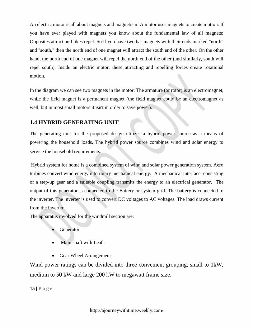
httpajourneywithtimeweeblycom
CHAPTER ndash 3
DESIGN AND CONSTRUCTION
12 | P a g e
httpajourneywithtimeweeblycom
CHAPTER 3 DESIGN AND CONSTRUCTION
31 WIND ENERGY
Wind result from air in motion Air in motion arises from a pressure gradient On a global basis
one primary forcing function causing surface winds from the poles toward the equator is
convective circulation Solar radiation heats the air near the equator and this low density heated
air is buoyed up At the surface it is displaced by cooler more dense higher pressure air flowing
from the poles In the upper atmosphere near the equator the air thus tend to flow back toward
the poles and away from the equator The net result is a global convective circulation with
surface wins from north to south in the northern hemisphere
It is clear from the above over simplified model that the wind is basically caused by the solar
energy irradiating the earth This is why wind utilization is considered a part of solar
technologyIt actuality the wind is much more complex The above model ignores the earth
rotation which causes a coriolis force resulting in an easterly wind velocity component in the
northern hemisphere There is the further complication of boundary layer frictional effects
between the moving air and the earth rough surface Mountains trees buildings and similar
obstructions impair stream line air flow Turbulence results and the wind velocity in a horizontal
direction markedly increase with altitude near the surface Local winds are caused by two
mechanisms The first is differential hating of land and water Solar isolation during the day is
readily converted to sensible energy of the land surface but is partly absorbed in layers below the
water surface and partly consume in evaporating some of that water The land mass becomes
hotter than the water which causes the air above the land to heat up and become warmer than
the air above water The warmer lighter air above the land rises and the cooler heavier air
above the water moves into replace it This is the mechanism of shore breezes At night the
direction of the breezes is reversed because the land mass cools to the sky more rapidly than the
water assuming a sky The second mechanism of local winds is caused by hills and mountain
sides The air above the slopes heats up during the day and cools down at night more rapidly
than the air above the low lands This causes heated air the day to rise along the slopes and
relatively cool heavy air to flow down at night Wind turbines produce rotational motion wind
energy is readily converted into electrical energy by connecting the turbine to an electric
13 | P a g e
httpajourneywithtimeweeblycom
generator The combination of wind turbine and generator is sometimes referred as an aero
generator A step-up transmission is usually required to match the relatively slow speed of the
wind rotor to the higher speed of an electric generator
In India the interest in the windmills was shown in the last fifties and early sixties A part from
importing a few from outside new designs was also developed but it was not sustained It is
only in the last few years that development work is going on in many institutions An important
reason for this lack of interest in wind energy must be that wind in India area relatively low and
vary appreciably with the seasons Data quoted by some scientists that for India wind speed
value lies between 5 kmhr to 15-20 kmhr These low and seasonal winds imply a high cost of
exploitation of wind energy Calculations based on the performance of a typical windmill have
indicated that a unit of energy derived from a windmill will be at least several times more
expensive than energy derivable from electric distribution lines at the standard rates provided
such electrical energy is at all available at the windmill site
The above argument is not fully applicable in rural areas for several reasons First electric power
is not and will not be available in many such areas due to the high cost of generation and
distribution to small dispersed users Secondly there is possibility of reducing the cost of the
windmills by suitable design Lastly on small scales the total first cost for serving a felt need
and low maintenance costs are more important than the unit cost of energy
The last point is illustrated easily dry cells provide energy at the astronomical cost of about
Rs300 per kWh and yet they are in common use in both rural and urban areas Wind energy
offers another source for pumping as well as electric power generation India has potential of
over 20000 MW for power generation and ranks as one of the promising countries for tapping
this source The cost of power generation from wind farms has now become lower than diesel
power and comparable to thermal power in several areas of our country especially near the
coasts Wind power projects of aggregate capacity of 8 MW including 7 wind farms projects of
capacity 685 MW have been established in different parts of the country of which 3 MW
capacity has been completed in 1989 by DNES Wind farms are operating successfully and have
already fed over 150 lakes units of electricity to the respective state grids Over 25 MW of
additional power capacity from wind is under implementation Under demonstration
14| P a g e
httpajourneywithtimeweeblycom
Programmer 271 wind pumps have been installed up to February 1989 Sixty small wind battery
charges of capacities 300 watts to 4 kW are under installation Likewise to stand-alone wind
electric generators of 10 to 25 kW are under installation
311 CONVERSION PRINCIPLES BLOCK DIAGRAM
Figure 4
A wind turbine is a machine that converts wind energy into electricity The generators are
connected to battery charging circuits and finally to large utility grids In windmills the
wind passes through the airfoil section of the blades and the lift produced generates a
torque which is then transformed to electricity in the generator The conversion of the
wind energy into the mechanical energy of the turbine and then finally to electricity As
the output of the wind turbine is dependent on the availability of the winds it is
intermittent and undependable They can however be used along with conventional
generators in a large grid and can reduce the loads of these generators when they are
generating The other option is to use storage devices like batteries and then discharge the
electricity uniformly
312 NATURE OF THE WIND
The circulation of air in the atmosphere is caused by the non-uniform heating of the earth surface
by the sun The air immediately above a warm area expands it is forced upwards by cool
denser air which flows in from surrounding areas causing a wind The nature of the terrain the
degree of cloud cover and the angle of the sun in the sky are all factors which influence this
process In general during the day the air above the land mass tends to heat up more rapidly
15 | P a g e
httpajourneywithtimeweeblycom
than the air over water In coastal regions this manifests itself in a strong onshore wind At
night the process is reversed because the air cools down more rapidly over the land and the
breeze therefore blows off shore the main planetary winds are caused in much the same way
Cool surface air sweeps down from the poles forcing the warm air over the topics to rise But the
direction of these massive air movements is affected by the rotation of the earth and the net
pressure areas in the countries-clockwise circulation of air around low pressure areas in the
northern hemisphere and clockwise circulation in the southern hemisphere The strength and
direction of these planetary winds change with the seasons as the solar input varies
Despite the winds intermittent nature wind patterns at any particular site remains remarkably
constant year by year Average wind speeds are greater in hilly and coastal areas than they are
well inland The winds also tend to blow more consistently and with greater strength over the
surface of the water where there is a less surface drag
Wind speeds increase with height They have traditionally been measured at a standard height
of ten meters where they are found to be 20-25 greater than close to the surface At a height of
60 m they may be 30-60 higher because of the reduction in the drag effect of the earth surface
313 WIND POWER
The power in the wind can be computed by using the concept of kinetics The wind will works
on the principle of converting kinetic energy of the wind to mechanical energy We know that
power is equal to energy per unit time The energy available is the kinetic energy of the wind
The kinetic energy of any particle is equal to one half its mass times the square of its velocity or
12m V2 The amount of air passing in unit time through an area A with velocity V is AV and
its mass m is equal to its volume multiplied by its density of air o
m=AV
( m is the mass of air transverse the area A swept by the rotating blades of a wind mill
type generator)
Substituting this value of the mass in the expression for the kinetic energy we obtain
kinetic energy = 12 AVV2 watts
=12 AV3 watts
16 | P a g e
httpajourneywithtimeweeblycom
Equation tells us that the maximum wind available the actual amount will be somewhat less
because all the available energy is not extractable-is proportional to the cube of the wind speed
It is thus evident that small increase in wind speed can have a marked effect on the power in the
wind
Equation also tells us that the power available is proportional to air density 1225 kgm3 at sea
level) It may vary 10-15 percent during the year because of pressure and temperature change It
changes negligibly with water content Equation also tells us that the wind power is proportional
to the intercept area Thus an aero turbine with a large swept area has higher power than a
smaller area machine but there are added implications Since the area is normally circular of
diameter D in horizontal axis aero turbines then A = 4 D2 (sqm) which when put in equation
gives
Available wind power P = frac12 4 D2V
3 watts
= 18 D2V
3
314 PRESSURE AND VELOCITY GRAPH
Figure 5
17 | P a g e
httpajourneywithtimeweeblycom
The power extracted by the rotor is equal to the product of the wind speed as it passes through
the rotor (ie Vr) and the pressure drop p in order to maximize the rotor power it would
therefore be desirable to have both wind speed and pressure drop as large as possible However
as V is increased for a given value of the free wind speed (and air density) increases at first
passes through a maximum and the decreases Hence for the specified free-wind speed there is
a maximum value of the rotor power
The fraction of the free flow wind power that can be extracted by a rotor is called the power-
coefficient thus
Power of wind rotor
Power coefficient =
Power available in the wind
Where power available is calculated from the air density rotor diameter and free wind speed as
shown above The maximum theoretical power coefficient is equal to 1627 or 0593 This
value cannot be exceeded by a rotor in a free-flow wind-stream
315 MAXIMUM POWER
The total power cannot be converted to mechanical power Consider a horizontal-axis propeller-
type windmill henceforth to be called a wind turbine which is the most common type used
today Assume that the wheel of such a turbine has thickness b Let pi and Vi are the wind
pressure and velocity at the upstream of the turbine Ve is less than Vi because the turbine
extracts kinetic energy
18 | P a g e
Considering the incoming air between I and a as a thermodynamic system and
assuming that the air density remains constant (since changes in pressure and
temperature are very small compared to ambient) that the potential energy is zero and
no heat or work are added or removed between i and a the general energy equation
reduces to the kinetic and flow energy-terms only
316 WIND ENERGY CONVERSION
Traditional windmills were used extensively in the middle Ages to mill grain and lift
water for land drainage and watering cattle Wind energy converters are still used for
these purposes today in some parts of the world but the main focus of attention now
lies with their use to generate electricity There is also growing interest in generating
heat from the wind for space and water heating and for glass-houses but the potential
market is much smaller than for electricity generation
The term ldquowind millrdquo is still widely used to describe wind energy conversion systems
however it is hardly adopt Description any more Modern wind energy conversion
systems are more correctly referred to as lsquoWECS aero generations lsquowind turbine
generators or simply lsquowind turbines The fact that the wind is variable and intermittent
source of energy is immaterial of some applications such as pumping water for land
drainage ndash provided of course that there is a broad match between the energy supplied
over any critical period and the energy required If the wind blows the job gets done
if it does not the job waits
However for many of the uses to which electricity is put the interruption of supply
may be highly inconvenient Operators or users of wind turbines must ensure that there
is some form of back-up to cover periods when there is insufficient (or too much) wind
available For small producers back-up can take the form of
(i) Battery storage
(ii) Connection with the local electricity distribution system or
For utilities responsible for public supply the integration of medium ndash sized and
large wind turbines into their distribution network could require some additional plant
which is capable of responding quickly to meet fluctuating demand
19 | P a g e
317 ENVIRONMENTAL ASPECTS
Wind turbines are not without environmental impact and their operation is not
entirely risk-free Following are the main effects due to a wind turbine
(i) Electromagnetic interference Interference with TV and other electromagnetic
communication systems is a possibility with wind turbines as it is with other tall
structures TV interference is most likely in areas where there is a weak signal because
of the distance from the transmitter where existing reception is none too good due to
the surrounding hills and where the wind turbine is exposed in good position to receive
and scatter the signals Dispensing with aerials and sending TV signals by cable in
areas that would otherwise be affected can overcome interference
(ii) Noise The noise produced by wind farms falls into two categories The first type
is a mechanical noise from the gearbox generating equipment and linkages and the
second type of aerodynamic in nature produced by the movement of the turbine blades
One component of the latter is the broad band noise which ranges up to several kilo
hertz and the other is a low frequency noise of 15-20 Hz Revolving blades generate
noise which can be heard in the immediate vicinity of the installation but noise does
not travel too far
(iii) Visual Effects Megawatts power generating wind turbines are massive structures
which would be quite visible over a wide area in some locations Variety
characteristics such as color pattern shape rotational speed and reflectance of blade
materials can be adjusted to modify the visual effects of wind turbines including the
land scape in which they are installed
32 SOLAR ENERGY
Solar energy is radiant light and heat from the Sun that is harnessed using a range of
ever-evolving technologies such as solar heating photovoltaics solar thermal energy
solar architecture molten salt power plants and artificial photosynthesis
It is an important source of renewable energy and its technologies are broadly
characterized as either passive solar or active solar depending on how they capture and
distribute solar energy or convert it into solar power Active solar techniques include
the use of photovoltaic systems concentrated solar power and solar water heating to
harness the energy Passive solar techniques include orienting a building to the Sun
20 | P a g e
selecting materials with favorable thermal mass or light-dispersing properties and
designing spaces that naturally circulate air
321 DIRECT METHOD OF UTILIZATION OF SOLAR ENERGY
The most useful way of harnessing solar energy is by directly converting it into
electricity by means of solar photo-voltaic cells Sunshine is incident on Solar cells in
this system of energy Conversion that is direct conversion of solar radiation into
electricity In the stage of conversion into thermodynamic from is absent The photo-
voltaic effect is defined as the generation of an electromotive force as a result of the
absorption of ionizing radiation Energy conversion devices which are used to convert
sunlight to electricity by use of the photo-voltaic effect are called solar cells
Figure 6
In recent years photo-voltaic power generation has been receiving considerable
attention as one of the more promising energy alternatives The reason for this rising
interest lie in PVrsquos direct conversion of sunlight to electricity the non-polluting nature
of the PV widespread are of PV generation has been hampered by economic factors
Here to force the low cost of conventional energy sunlight has obviated the
development of a broad-based PV technology At the present time PV generation can
be justified only for special situations mostly for remote sites where utility lines on
other conventional means of furnishing energy may be prohibitively expensive and is
21 | P a g e
one of the most attractive non-conventional energy sources of proven reliability from
the micro to the Mega-watt level
Like other energy system this system also has some disadvantages
(1) Distributed nature of solar energy
(2) Absence of energy storage
(3) Relatively high capital cost
322 PHOTOVOLTAIC PRINCIPLES
The photo-voltaic effect can be observed in nature in a variety of materials that have
shown that the best performance in sunlight is the semiconductors as stated above
When photons from the sun are absorbed in a semiconductor that create free electrons
with higher energies than the created there must be an electric field to induce these
higher energy electrons to flow out of the semi-conductor to do useful work A
junction of materials which have different electrical properties provides the electric
field in most solar cells
To obtain a useful power output from photon interaction in a semiconductor three
processes are required
1) The photon has to be absorbed in the active part of the material and
result in electrons being excited to a higher energy potential
2) The electron hole charge carriers created by the absorption must be
physically separated and moved to the edge of the cell
3) The charge carriers must be removed from the cell and delivered to
useful load before they lose extra potential
For completing the above processes a solar cell consists of-
(a) Semi-conductor in which electron hole pairs are created by
absorption of incident solar radiation
(b) Region containing a drift field for charge separation
(c) Charge collecting fronts and back electrodes
22 | P a g e
The photo-voltaic effect can be described easily for p-n junction in a semi-conductor
In an intrinsic semi-conductor such as silicon each one of the four valence electrons of
the material atom is tied in a chemical bond and there are no free electrons at absolute
zero If a piece of such a material is doped on one side by a five valance electron
material such as arsenic or phosphorus there will be an excess of electrons in that side
becoming an n-type semi-conductor
The excess electrons will be practically free to move in the semi-conductor lattice
When a three valence electron material such as boron dopes the other side of the same
piece there will be deficiency of electrons leading to a p-type semi-conductor This
deficiency is expressed in terms of excess of holes free to move in the lattice Such a
piece of semi-conductor with one side of the p-type and the other of the n-type is
called p-n junction In this junction after the protons are absorbed the free electrons of
the n-side will tends to flow to the p-side and the holes of the p-side will tend to flow
to the n-region to compensate for their respective deficiencies This diffusion will
create an electric field from the n-region to the p-region This field will increase until it
reaches equilibrium for V the sum of the diffusion potentials for holes and electrons
33 SOUND ENERGY
In physics energy (from the Greek ἐνέργεια - energeia activity operation from
ἐνεργός - energos active working[1]
) is a quantity that can be assigned to every
particle object and system of objects as a consequence of the state of that particle
object or system of objects Different forms of energy include kinetic potential
thermal gravitational sound elastic light and electromagnetic energy The forms of
energy are often named after a related force German physicist Hermann von Helmholtz
established that all forms of energy are equivalent - energy in one form can disappear
but the same amount of energy will appear in another form Energy is subject to a
conservation law Energy is a scalar physical quantity In the International System of
Units (SI) energy is measured in joules but in some fields other units such as kilowatt-
hours and kilocalories are also used Any form of energy can be transformed into
another form When energy is in a form other than heat it may be transformed with
good or even perfect efficiency to any other type of energy In all such energy
transformation processes the total energy remains the same Energy may not be created
nor destroyed This principle the conservation of energy was first postulated in the
23 | P a g e
early 19th century and applies to any isolated system According to Noethers theorem
the conservation of energy is a consequence of the fact that the laws of physics do not
change over time
Although the total energy of a system does not change with time its value may depend
on the frame of reference For example a seated passenger in a moving airplane has
zero kinetic energy relative to the airplane but non-zero kinetic energy (and higher
331 TRANSFORMATION OF ENERGY
At its highest points the kinetic energy is zero and the gravitational potential energy is
at maximum At its lowest point the kinetic energy is at maximum and is equal to the
decrease of potential energy If one (unrealistically) assumes One form of energy can
often be readily transformed into another with the help of a device- for instance a
battery from chemical energy to electric energy a dam gravitational potential energy
to kinetic energy of moving water (and the blades of a turbine) and ultimately to
electric energy through an electric generator Similarly in the case of a chemical
explosion chemical potential energy is transformed to kinetic energy and thermal
energy in a very short time Yet another example that there is no friction the
conversion of energy between these processes is perfect and the pendulum will
continue swinging forever
Energy gives rise to weight and is equivalent to matter and vice versa The formula
E = mcsup2 derived by Albert Einstein (1905) quantifies the relationship between mass
and rest energy within the concept of special relativity In different theoretical
frameworks similar formulas were derived by J J Thomson (1881) Henri Poincare
(1900) Friedrich Hasenohrel (1904) and others (see Mass-energy equivalence History
for further information) Since c2 is extremely large relative to ordinary human scales
the conversion of ordinary amount of mass (say 1 kg) to other forms of energy can
liberate tremendous amounts of energy (~9x10¹⁶
joules) as can be seen in nuclear
reactors and nuclear weapons Conversely the mass equivalent of a unit of energy is
minuscule which is why a loss of energy from most systems is difficult to measure by
weight unless the energy loss is very large Examples of energy transformation into
matter (particles) are found in high energy nuclear physics
24 | P a g e
In nature transformations of energy can be fundamentally classed into two kinds those
that are thermodynamically reversible and those that are thermodynamically
irreversible A reversible process in thermodynamics is one in which no energy is
dissipated (spread) into empty energy states available in a volume from which it
cannot be recovered into more concentrated forms (fewer quantum states) without
degradation of even more energy A reversible process is one in which this sort of
dissipation does not happen For example conversion of energy from one type of
potential field to another is reversible as in the pendulum system described above In
processes where heat is generated quantum states of lower energy present as possible
exicitations in fields between atoms act as a reservoir for part of the energy from
which it cannot be recovered in order to be converted with 100 efficiency into other
forms of energy In this case the energy must partly stay as heat and cannot be
completely recovered as usable energy except at the price of an increase in some other
kind of heat-like increase in disorder in quantum states in the universe (such as an
expansion of matter or a randomization in a crystal)
As the universe evolves in time more and more of its energy becomes trapped in
irreversible states (ie as heat or other kinds of increases in disorder) This has been
referred to as the inevitable thermodynamic heat death of the universe In this heat
death the energy of the universe does not change but the fraction of energy which is
available to do produce work through a heat engine or be transformed to other usable
forms of energy (through the use of generators attached to heat engines) grows less and
less
332 SOUND
Sound energy is also a type of wave motion We are heard by others when we talk
because of the sound energy we produce It is due to the effect of the air molecules
vibrating when we talk The vibrating molecules hit our eardrums which enable us to
hear others talk Sound energy may be converted into electrical energy for
transmission and later the electrical energy can be converted back into sound energy at
the receiving end An example of such transformations could be seen in the microphone
and the loudspeaker Sound like heat energy is easily lost The transformation of one
form of energy into another may be accompanied by losses in the form of sound andor
heat that are often not desirable
25 | P a g e
Sound is a form of mechanical vibration which propagates through any mechanical
medium Sound is a vibration or wave of air molecules caused by the motion of an
object The wave is a compression wave where the density of the molecules is higher
This wave travels through the air at a speed dependent on the temperature A sound
wave contains energy which in turn means it can make things move However if the
wave strikes something solid the wave will bounce back -- an echo Sound energy can
be changed into other forms of energy eg electrical energy and vice versa this is one
of its properties that allow us to communicate by telephone
333 MICROPHONES
Figure 7
Sound energy we can hear travels only so far before it soaks away into the world
around us Until electrical microphones were invented in the late 19th century there
was no satisfactory way to send sounds to other places You could shout but that
carried your words only a little further You couldnt shout in New York City and make
yourself heard in London And you couldnt speak in 1715 and have someone listen to
what you said in 1750 Remarkably such things are possible today by converting
sound energy into electricity and information we can store microphones make it
possible to send the sounds of our voices our music and the noises in our world to
other places and other times How do microphones work letrsquos take a closer look
26 | P a g e
Photo A high-quality professional microphone typical of the ones used by radio DJs
Photo by Gary Ward courtesy of US Navy
3 34 MICROPHONES REVERSE OF LOUDSPEAKER
If youve read our article on loudspeakers youll already know how microphones work
because theyre literally loudspeakers working in reverse Indeed you can actually take
a loudspeaker and wire it into an electrical circuit so it works as a microphone if you
speak into it Intercoms (electrical gadgets that allow you to speak to someone in the
next room) often have a combined loudspeakermicrophone It works as a microphone
when you press a button to speak into it and as a loudspeaker when the person next
door pushes the button on their intercom instead Its exactly the same piece of
equipment working in two different ways Hows that possible
In a loudspeaker electricity flows into a coil of metal wire wrapped around (or in front
of) a permanent magnet The changing pattern of electricity in the coil creates a
magnetic field all around it that pushes against the field the permanent magnet creates
This makes the coil move The coil is attached to a big flat disc called a diaphragm or
cone so as the coil moves the diaphragm moves too The moving diaphragm pushes
air back and forth into the room and creates sound waves we can hear
In a microphone there are almost identical parts but they work in reverse Sound waves
created by your voice push against a diaphragm making a coil move near to a magnet
This makes an electric current flow through the coil into an electrical circuit By using
this current to drive sound recording equipment you can effectively store the sound
forever more Or you could amplify (boost the size of) the current and then feed it into
a loudspeaker turning the electricity back into much louder sound Thats how PA
(personal address) systems electric guitar amplifiers and rock concert amplifiers work
27 | P a g e
335 HOW MICROPHONES WORK
figure 8
1 Sound waves carry energy toward the microphone
2 The diaphragm moves back and forth when sound waves hit it
3 The coil attached to the diaphragm moves back and forth as well
4 The permanent magnet produces a magnetic field that cuts through the coil As
the coil moves back and forth through the magnetic field an electric current flows
through it
5 The electric current flows out from the microphone to an amplifier or sound
recording device
336 TYPEOF MICROPHONES
All microphones turn sound energy into electrical energy but there are various
different kinds that work in slightly different ways Dynamic microphones are just
ordinary microphones that use diaphragms magnets and coils Condenser microphones
work a slightly different way by using a diaphragm to move the metal plates of a
capacitor (an electric-charge storing device) and generate a current that way Most
microphones are omnidirectional which means they pick up sound equally well from
any direction If youre recording something like a TV news reporter in a noisy
environment or a rare bird tweeting in a distant hedgerow youre better off using a
unidirectional microphone that picks up sound from one specific direction
Microphones described as cardioid and hyper cardioid pick up sounds in a kind of
heart-shaped (thats what cardioid means) pattern gathering more sound from one
direction than another As their name suggests you can target shotgun microphones so
28 | P a g e
they pick up sounds from a very specific location because they are highly directional
Wireless microphones use radio transmitters to send their signals to and from an
amplifier or other audio equipment (thats why theyre often called radio mics)
Microphones convert acoustic energy into electrical energy sound makes mics
membrane vibrate the vibrations make the material (for example coal dust) placed
beneath the membrane to be pressed periodically - in accordance with the sound waves
received - the electrical resistance of the material changes in the same key and so the
direct current passing through the material is thus changing its amplitude Or it may be
two membranes forming a capacitor whose capacity changing in accordance with the
sound waves pressing is then processed in an electronic processor
34 SHOCK ABSORBERS
341 REGENRATIVE SHOCK ABSORBER
A regenerative shock absorber is a type of shock absorber that converts parasitic
intermittent linear motion and vibration into useful energy such as electricity
Conventional shock absorbers simply dissipate this energy as heat
When used in an electric vehicle or hybrid electric vehicle the electricity generated by
the shock absorber can be diverted to its powertrain to increase battery life In non-
electric vehicles the electricity can be used to power accessories such as air
conditioning Several different systems have been developed recently though they are
still in stages of development and not installed on production vehicles
DESIGN -1
Figure 9
The project introduces a novel passive suspension system for ground vehicles
Hndash solenoid coil
G- spring action to provide motion
Indash electrical energy out
29 | P a g e
A- permanent magnets to provide induced emf
DESIGN -2
Another design to generate electricity by shock absorbers
Figure 10
A-Generator ndash Stepper motor
B- Rod to connect wheel
C- Rubber springcover to protect dust
E - Shocker rod area dndash rack and pinion gear assembly
G- Wheel
Fndash Electricity out for battery charging
Modifications in the above structure a modified design is shown for the shocker
motion provided by rack and pinion gear assembly that generates power The motor
(generator) will operate clock and anti -clock to operate as it sense the path the above
design is very impractical in this way and further holes or bumps on the road Shocker
rod activates rack and pinion up and down motion that run the motor (generator) in
clock and anti -clock motion
30 | P a g e
Area required for actual implementation in vehicle This is just an idea
342 ELECTRICITY GENERATING SHOCK ABSORBERS
Figure 11
While some study ways of electronically controlling the shock absorbers and giving
you a smooth and steady ride and others are seeking ways to convert the heat
generated by the engine into electricity a team of undergraduate MIT students invented
a shock absorber that harnesses the energy from the very bumps it hits Several truck
manufacturers and the US military have given them attention and planned to use their
technology in their cars
While hybrid cars recover braking energy by the same dynamo principle (applying a
big consumer on a coil linked to the wheel while the magnetic chassis opposes it) The
system works like a reversed DC motor The same principle is applied in these
studentsrsquo shock absorbers only in a somewhat more efficient way they use a hydraulic
system forcing a fluid through a turbine attached to a generator (the inverted DC motor
I was talking about earlier)
The system is controlled by an active electronic system that optimizes the damping
providing a smoother ride than conventional shocks while generating electricity to
recharge the batteries or operate electrical equipment
31 | P a g e
figure12
343 SHOCK ABSORBER ndash AN INTRODUCTION
A shock absorber in common parlance (or damper in technical use) is a mechanical
device designed to smooth out or dampen a sudden shock impulse and dissipate kinetic
energy It is analogous to a resistor in an electric RLC circuit
Figure 13
Shock absorber with internal reservoir The components are the rod (A) the piston
with seals (B) the cylinder (C) the oil reservoir (D) the floating piston (E) and the air
chamber (F)
32 | P a g e
344 EXPLANATION
Shock absorbers must absorb or dissipate energy One design consideration when
designing or choosing a shock absorber is where that energy will go In most dashpots
energy is converted to heat inside the viscous fluid In hydraulic cylinders the
hydraulic fluid will heat up while in air cylinders the hot air is usually exhausted to
the atmosphere In other types of dashpots such as electromagnetic ones the dissipated
energy can be stored and used later
345 DESCRIPTION
Pneumatic and hydraulic shock absorbers commonly take the form of a cylinder with a
sliding piston inside The cylinder is filled with a fluid (such as hydraulic fluid) or air
This fluid filled pistoncylinder combination is a dashpot
346 APPLICATIONS
Shock absorbers are an important part of automobile and motorcycle suspensions
aircraft landing gear and the supports for many industrial machines Large shock
absorbers have also been used in structural engineering to reduce the susceptibility of
structures to earthquake damage and resonance
Figure14
Rear shock absorber and spring of a BMW R755 motorcycle
33 | P a g e
347 VEHICLES SUSPENSION
In a vehicle it reduces the effect of travelling over rough ground leading to improved
ride quality Without shock absorbers the vehicle would have a bouncing ride as
energy is stored in the spring and then released to the vehicle possibly exceeding the
allowed range of suspension movement Control of excessive suspension movement
without shock absorption requires stiffer (higher rate) springs which would in turn give
a harsh ride Shock absorbers allow the use of soft (lower rate) springs while
controlling the rate of suspension movement in response to bumps They also along
with hysteresis in the tire itself damp the motion of the unsparing weight up and down
on the springiness of the tire Since the tire is not as soft as the springs effective wheel
bounce damping may require stiffer shocks than would be ideal for the vehicle motion
alone
Spring-based shock absorbers commonly use coil springs or leaf springs though
torsion bars can be used in torsional shocks as well Ideal springs alone however are
not shock absorbers as springs only store and do not dissipate or absorb energy
Vehicles typically employ both springs or torsion bars as well as hydraulic shock
absorbers In this combination shock absorber is reserved specifically for the
hydraulic piston that absorbs and dissipates vibration
348 STRUCTURES
Applied to a structure such as a building or bridge it may be part of a seismic retrofit or
as part of new earthquake resistant construction In this application it allows yet
restrains motion and absorbs resonant energy which can cause excessive motion and
eventual structural failure
349 TYPES OF SHOCK ABSORBERS
There are several commonly-used approaches to shock absorption
Hysteresis (hysteresis is like a memory of the material if you press down rubber
disks they tend to back to its normal uncompressed state as the precession of fingers is
relieved) of structural material for example the compression of rubber disks stretching
of rubber bands and cords bending of steel springs or twisting of torsion bars
Hysteresis is the tendency for otherwise elastic materials to rebound with less force
than was required to deform them Simple vehicles with no separate shock absorbers
are damped to some extent by the hysteresis of their springs and frames
Dry friction as used in wheel brakes by using disks (classically made of leather) at
the pivot of a lever with friction forced by springs Used in early automobiles such as
the Ford Model T up through some British cars of the 1940s Although now considered
obsolete an advantage of this system is its mechanical simplicity the degree of
damping can be easily adjusted by tightening or loosening the screw clamping the
disks and it can be easily rebuilt with simple hand tools A disadvantage is that the
damping force tends not to increase with the speed of the vertical motion
34 | P a g e
Solid state tapered chain shock absorbers using one or more tapered axial
alignment(s) of granular spheres typically made of metals such as nitinol in a casing
Fluid friction for example the flow of fluid through a narrow orifice (hydraulics)
constitute the vast majority of automotive shock absorbers An advantage of this type is
that using special internal valving the absorber may be made relatively soft to
compression (allowing a soft response to a bump) and relatively stiff to extension
controlling jounce which is the vehicle response to energy stored in the springs
similarly a series of valves controlled by springs can change the degree of stiffness
according to the velocity of the impact or rebound Specialized shock absorbers for
racing purposes may allow the front end of a dragster to rise with minimal resistance
under acceleration then strongly resist letting it settle thereby maintaining a desirable
rearward weight distribution for enhanced traction Some shock absorbers allow tuning
of the ride via control of the valve by a manual adjustment provided at the shock
absorber In more expensive vehicles the valves may be remotely adjustable offering
the driver control of the ride at will while the vehicle is operated The ultimate control
is provided by dynamic valve control via computer in response to sensors giving both a
smooth ride and a firm suspension when needed Many shock absorbers contain
compressed nitrogen to reduce the tendency for the oil to foam under heavy use
Foaming temporarily reduces the damping ability of the unit In very heavy duty units
used for racing andor off-road use there may even be a secondary cylinder connected
to the shock absorber to act as a reservoir for the oil and pressurized gas Another
variation is the Magneto rheological damper which changes its fluid characteristics
through an electromagnet
Compression of a gas for example pneumatic shock absorbers which can act like
springs as the air pressure is building to resist the force on it Once the air pressure
reaches the necessary maximum air dashpots will act like hydraulic dashpots In
aircraft landing gear air dashpots may be combined with hydraulic damping to reduce
bounce Such struts are called oleo struts (combining oil and air) [3]
Magnetic effects Eddy current dampers are dashpots that are constructed out of a
large magnet inside of a non-magnetic electrically conductive tube
Inertial resistance to acceleration for example prior to 1966 [4] the Citroeumln 2CV
had shock absorbers that damp wheel bounce with no external moving parts These
consisted of a spring-mounted 35 kg (775 lb) iron weight inside a vertical cylinder [5]
and are similar to yet much smaller than versions of the tuned mass dampers used on
tall buildings
Composite hydro pneumatic devices which combine in a single device spring
action shock absorption and often also ride-height control as in some models of the
Citroeumln automobile
35 | P a g e
Conventional shock absorbers combined with composite pneumatic springs with
which allow ride height adjustment or even ride height control seen in some large
trucks and luxury sedans such as certain Lincoln and most Land Rover automobiles
Ride height control is especially desirable in highway vehicles intended for occasional
rough road use as a means of improving handling and reducing aerodynamic drag by
lowering the vehicle when operating on improved high speed roads
35 ASSEMBLY OF HEV
STEP 1- Firstly we purchase or collect all component of HEV that is needed such as
nut bolt cardboard solar plate transformer wire DC motor dynamometer etc
STEP 2- Take two hard board sheet Cut them with as shown in diagram
STEP 3- Drill two hole for one wheel (d=97cm) and for four drilled hole as shown in
above diagram
STEP4- And 2 rear wheel are driven by 2 DC motor (12V) and 2 front wheel is free
36 | P a g e
STEP 5- And 4 hole is drilled in both sheet to assemble with nut amp bolt (h=13cm
d=16cm) and open helical coil spring is fixed between them
STEP 6- PCB plate contains four LED each LED indicate each power of source
37 | P a g e
STEP 7- A wooden strip is fixed to lower hard board to drive dynamometer and a
transformer setup to increase power given by speaker
STEP 8- A solar plate (9V) is used to absorb solar rays and a dynamometer for wind
and these three sources (Dynamometer 1 solar plate Dynamometer 2) are connected
with PCB plate A circuit is designed in PCB plate for power storage in battery
Dimension of solar plate (18cmtimes21cm)
38 | P a g e
STEP 9- After that PCB is connected with switches via wire to drive the HEV
Switch 1 ndash Forward movement
Switch 2- Backward movement
And battery is connected for power storage
39 | P a g e
CHAPTER ndash 4
COST ANALYSIS
40 | P a g e
CHAPTER 4 COST ANALYSIS
41 COST ESTIMATION
To ensure sustained and healthy growth of hybrid electric vehicle (HEV) it is
necessary to rationally evaluate the cost of production of Energy and to determine a
selling rate which should be acceptable to consumers and attractive for investors
EXPENDITURE TABLE
LABOUR COST Drilling Soldering Gluester Screw Tightning Sheet Cutting
Finishing
Cost = Rs 800
41 | P a g e
SNO COMPONENT NAME QUANTITY PRICE
1 SOLAR PANEL 1 700
2 TRANSFORMER 1 200
3 BATTERY 1 500
4 DC MOTOR 2 500
5 SPEAKER 1 200
6 DYNAMOMETER 2 500
7 WHEEL 4 250
8 WOODEN PLATE 2 100
9 OTHER COMPONENTS 800
10 TOTAL COST 3750
TRANSPORTATION COST Rs 1000
OVERHEAD CHARGES The overhead charges are arrived by ldquoManufacturing costrdquo
Manufacturing Cost = (Material Cost + Labour cost + Transportation Cost)
= Rs (3750 + 800 + 1000)
= Rs 5550
Overhead Charges = 10 of the manufacturing cost
= Rs 555
TOTAL COST
Total cost = (Material Cost + Labour cost + Transportation Cost + Overhead
Charges)
= Rs (3750 + 800 + 1000 + 555)
Total cost for this project = Rs 6105
42 | P a g e
CONCLUSION
The design of the project envisages a household power system which could have its
own generation and replication of all functions performed by the electricity board
towards energy control within the household itself including load shedding per room
power switching control etc However on analyzing the completed project based on
current status only some main functions of a control center were possible to replicate in
the working system The following controls have been successfully implemented
Power onoff control
Monitoring control
However control functions like load shedding and each room switching control could
not be actuated because of the programming conditional complexity involved The
actuation of these controls requires an actual household as only then the conditional
instances can be encapsulated in program modules Since for principle display such an
arrangement is not possible hence under current implementation the controls have been
limited The actuation of the system in future on actual households would allow for
greater programming flexibility and as such all designed controls could be
conceptualized and tested to display a completely independent household power system
with integrated generation transmission distribution and control
43 | P a g e
FUTURE SCOPE OF PROJECT
The hybrid car designs of the future are including sports car models that
have been all-time favorites with the world in the past and are now being
revived with the brand new hybrid engine in mind With a mindset of
grasping and expanding the propulsion features that are somewhat limited
in todays hybrid car designs there are retro styling efforts that are
focusing on providing hybrid cars with optional V8 engine capacities
There are considerations in place to use solar cells in the framework of
hybrid automobiles The future hybrid car will need to focus more on
greenhouse gases that negatively affect the environment as well as a hybrid
car that will be even more fuel efficient Speculations are on about the
future of hybrid cars With relatively new technology some believe that
hybrid cars are fast turning into the cars of future Consumers are ready to
take chance with the advance technology which hybrid cars have on offer
Today Honda and Toyota are the two prominent companies producing
hybrid cars
44 | P a g e
REFERENCES
1 Rushikesh Trushar Soni lsquoHybrid Electric Vehiclersquo IOSR Journal of
Mechanical and Civil Engineering (IOSR-JMCE) e-ISSN 2278-1684p-
ISSN 2320-334X Volume 12 Issue 2 Ver VI (Mar - Apr 2015) PP 11-
14
2 Parag Kulkarni (2015) ldquoReview of Hybrid Electrical Vehiclesrdquo
International Journal of Emerging Research in Management ampTechnology
ISSN 2278-9359 (Volume-4 Issue-3)
3 T Vignesh(1) G Vinetha(2) T Kalaimathi(3) S Sathishkumar(4) D
Silambarasan(5) ldquoDesign and Implementation of Hybrid Electric Vehicles
using Renewable Energy Sourcesrdquo IJSRD - International Journal for
Scientific Research amp Development| Vol 4 Issue 12 2017 | ISSN
(online) 2321-0613
4 httpsenwikipediaorgwikiAlternative_fuel_vehicle
5 httpnptelacincourses108103009
6 B R Gupta Generation of electrical energy S Chand Publication
45 | P a g e
httpajourneywithtimeweeblycom
CHAPTER 3 DESIGN AND CONSTRUCTION
31 WIND ENERGY
Wind result from air in motion Air in motion arises from a pressure gradient On a global basis
one primary forcing function causing surface winds from the poles toward the equator is
convective circulation Solar radiation heats the air near the equator and this low density heated
air is buoyed up At the surface it is displaced by cooler more dense higher pressure air flowing
from the poles In the upper atmosphere near the equator the air thus tend to flow back toward
the poles and away from the equator The net result is a global convective circulation with
surface wins from north to south in the northern hemisphere
It is clear from the above over simplified model that the wind is basically caused by the solar
energy irradiating the earth This is why wind utilization is considered a part of solar
technologyIt actuality the wind is much more complex The above model ignores the earth
rotation which causes a coriolis force resulting in an easterly wind velocity component in the
northern hemisphere There is the further complication of boundary layer frictional effects
between the moving air and the earth rough surface Mountains trees buildings and similar
obstructions impair stream line air flow Turbulence results and the wind velocity in a horizontal
direction markedly increase with altitude near the surface Local winds are caused by two
mechanisms The first is differential hating of land and water Solar isolation during the day is
readily converted to sensible energy of the land surface but is partly absorbed in layers below the
water surface and partly consume in evaporating some of that water The land mass becomes
hotter than the water which causes the air above the land to heat up and become warmer than
the air above water The warmer lighter air above the land rises and the cooler heavier air
above the water moves into replace it This is the mechanism of shore breezes At night the
direction of the breezes is reversed because the land mass cools to the sky more rapidly than the
water assuming a sky The second mechanism of local winds is caused by hills and mountain
sides The air above the slopes heats up during the day and cools down at night more rapidly
than the air above the low lands This causes heated air the day to rise along the slopes and
relatively cool heavy air to flow down at night Wind turbines produce rotational motion wind
energy is readily converted into electrical energy by connecting the turbine to an electric
13 | P a g e
httpajourneywithtimeweeblycom
generator The combination of wind turbine and generator is sometimes referred as an aero
generator A step-up transmission is usually required to match the relatively slow speed of the
wind rotor to the higher speed of an electric generator
In India the interest in the windmills was shown in the last fifties and early sixties A part from
importing a few from outside new designs was also developed but it was not sustained It is
only in the last few years that development work is going on in many institutions An important
reason for this lack of interest in wind energy must be that wind in India area relatively low and
vary appreciably with the seasons Data quoted by some scientists that for India wind speed
value lies between 5 kmhr to 15-20 kmhr These low and seasonal winds imply a high cost of
exploitation of wind energy Calculations based on the performance of a typical windmill have
indicated that a unit of energy derived from a windmill will be at least several times more
expensive than energy derivable from electric distribution lines at the standard rates provided
such electrical energy is at all available at the windmill site
The above argument is not fully applicable in rural areas for several reasons First electric power
is not and will not be available in many such areas due to the high cost of generation and
distribution to small dispersed users Secondly there is possibility of reducing the cost of the
windmills by suitable design Lastly on small scales the total first cost for serving a felt need
and low maintenance costs are more important than the unit cost of energy
The last point is illustrated easily dry cells provide energy at the astronomical cost of about
Rs300 per kWh and yet they are in common use in both rural and urban areas Wind energy
offers another source for pumping as well as electric power generation India has potential of
over 20000 MW for power generation and ranks as one of the promising countries for tapping
this source The cost of power generation from wind farms has now become lower than diesel
power and comparable to thermal power in several areas of our country especially near the
coasts Wind power projects of aggregate capacity of 8 MW including 7 wind farms projects of
capacity 685 MW have been established in different parts of the country of which 3 MW
capacity has been completed in 1989 by DNES Wind farms are operating successfully and have
already fed over 150 lakes units of electricity to the respective state grids Over 25 MW of
additional power capacity from wind is under implementation Under demonstration
14| P a g e
httpajourneywithtimeweeblycom
Programmer 271 wind pumps have been installed up to February 1989 Sixty small wind battery
charges of capacities 300 watts to 4 kW are under installation Likewise to stand-alone wind
electric generators of 10 to 25 kW are under installation
311 CONVERSION PRINCIPLES BLOCK DIAGRAM
Figure 4
A wind turbine is a machine that converts wind energy into electricity The generators are
connected to battery charging circuits and finally to large utility grids In windmills the
wind passes through the airfoil section of the blades and the lift produced generates a
torque which is then transformed to electricity in the generator The conversion of the
wind energy into the mechanical energy of the turbine and then finally to electricity As
the output of the wind turbine is dependent on the availability of the winds it is
intermittent and undependable They can however be used along with conventional
generators in a large grid and can reduce the loads of these generators when they are
generating The other option is to use storage devices like batteries and then discharge the
electricity uniformly
312 NATURE OF THE WIND
The circulation of air in the atmosphere is caused by the non-uniform heating of the earth surface
by the sun The air immediately above a warm area expands it is forced upwards by cool
denser air which flows in from surrounding areas causing a wind The nature of the terrain the
degree of cloud cover and the angle of the sun in the sky are all factors which influence this
process In general during the day the air above the land mass tends to heat up more rapidly
15 | P a g e
httpajourneywithtimeweeblycom
than the air over water In coastal regions this manifests itself in a strong onshore wind At
night the process is reversed because the air cools down more rapidly over the land and the
breeze therefore blows off shore the main planetary winds are caused in much the same way
Cool surface air sweeps down from the poles forcing the warm air over the topics to rise But the
direction of these massive air movements is affected by the rotation of the earth and the net
pressure areas in the countries-clockwise circulation of air around low pressure areas in the
northern hemisphere and clockwise circulation in the southern hemisphere The strength and
direction of these planetary winds change with the seasons as the solar input varies
Despite the winds intermittent nature wind patterns at any particular site remains remarkably
constant year by year Average wind speeds are greater in hilly and coastal areas than they are
well inland The winds also tend to blow more consistently and with greater strength over the
surface of the water where there is a less surface drag
Wind speeds increase with height They have traditionally been measured at a standard height
of ten meters where they are found to be 20-25 greater than close to the surface At a height of
60 m they may be 30-60 higher because of the reduction in the drag effect of the earth surface
313 WIND POWER
The power in the wind can be computed by using the concept of kinetics The wind will works
on the principle of converting kinetic energy of the wind to mechanical energy We know that
power is equal to energy per unit time The energy available is the kinetic energy of the wind
The kinetic energy of any particle is equal to one half its mass times the square of its velocity or
12m V2 The amount of air passing in unit time through an area A with velocity V is AV and
its mass m is equal to its volume multiplied by its density of air o
m=AV
( m is the mass of air transverse the area A swept by the rotating blades of a wind mill
type generator)
Substituting this value of the mass in the expression for the kinetic energy we obtain
kinetic energy = 12 AVV2 watts
=12 AV3 watts
16 | P a g e
httpajourneywithtimeweeblycom
Equation tells us that the maximum wind available the actual amount will be somewhat less
because all the available energy is not extractable-is proportional to the cube of the wind speed
It is thus evident that small increase in wind speed can have a marked effect on the power in the
wind
Equation also tells us that the power available is proportional to air density 1225 kgm3 at sea
level) It may vary 10-15 percent during the year because of pressure and temperature change It
changes negligibly with water content Equation also tells us that the wind power is proportional
to the intercept area Thus an aero turbine with a large swept area has higher power than a
smaller area machine but there are added implications Since the area is normally circular of
diameter D in horizontal axis aero turbines then A = 4 D2 (sqm) which when put in equation
gives
Available wind power P = frac12 4 D2V
3 watts
= 18 D2V
3
314 PRESSURE AND VELOCITY GRAPH
Figure 5
17 | P a g e
httpajourneywithtimeweeblycom
The power extracted by the rotor is equal to the product of the wind speed as it passes through
the rotor (ie Vr) and the pressure drop p in order to maximize the rotor power it would
therefore be desirable to have both wind speed and pressure drop as large as possible However
as V is increased for a given value of the free wind speed (and air density) increases at first
passes through a maximum and the decreases Hence for the specified free-wind speed there is
a maximum value of the rotor power
The fraction of the free flow wind power that can be extracted by a rotor is called the power-
coefficient thus
Power of wind rotor
Power coefficient =
Power available in the wind
Where power available is calculated from the air density rotor diameter and free wind speed as
shown above The maximum theoretical power coefficient is equal to 1627 or 0593 This
value cannot be exceeded by a rotor in a free-flow wind-stream
315 MAXIMUM POWER
The total power cannot be converted to mechanical power Consider a horizontal-axis propeller-
type windmill henceforth to be called a wind turbine which is the most common type used
today Assume that the wheel of such a turbine has thickness b Let pi and Vi are the wind
pressure and velocity at the upstream of the turbine Ve is less than Vi because the turbine
extracts kinetic energy
18 | P a g e
Considering the incoming air between I and a as a thermodynamic system and
assuming that the air density remains constant (since changes in pressure and
temperature are very small compared to ambient) that the potential energy is zero and
no heat or work are added or removed between i and a the general energy equation
reduces to the kinetic and flow energy-terms only
316 WIND ENERGY CONVERSION
Traditional windmills were used extensively in the middle Ages to mill grain and lift
water for land drainage and watering cattle Wind energy converters are still used for
these purposes today in some parts of the world but the main focus of attention now
lies with their use to generate electricity There is also growing interest in generating
heat from the wind for space and water heating and for glass-houses but the potential
market is much smaller than for electricity generation
The term ldquowind millrdquo is still widely used to describe wind energy conversion systems
however it is hardly adopt Description any more Modern wind energy conversion
systems are more correctly referred to as lsquoWECS aero generations lsquowind turbine
generators or simply lsquowind turbines The fact that the wind is variable and intermittent
source of energy is immaterial of some applications such as pumping water for land
drainage ndash provided of course that there is a broad match between the energy supplied
over any critical period and the energy required If the wind blows the job gets done
if it does not the job waits
However for many of the uses to which electricity is put the interruption of supply
may be highly inconvenient Operators or users of wind turbines must ensure that there
is some form of back-up to cover periods when there is insufficient (or too much) wind
available For small producers back-up can take the form of
(i) Battery storage
(ii) Connection with the local electricity distribution system or
For utilities responsible for public supply the integration of medium ndash sized and
large wind turbines into their distribution network could require some additional plant
which is capable of responding quickly to meet fluctuating demand
19 | P a g e
317 ENVIRONMENTAL ASPECTS
Wind turbines are not without environmental impact and their operation is not
entirely risk-free Following are the main effects due to a wind turbine
(i) Electromagnetic interference Interference with TV and other electromagnetic
communication systems is a possibility with wind turbines as it is with other tall
structures TV interference is most likely in areas where there is a weak signal because
of the distance from the transmitter where existing reception is none too good due to
the surrounding hills and where the wind turbine is exposed in good position to receive
and scatter the signals Dispensing with aerials and sending TV signals by cable in
areas that would otherwise be affected can overcome interference
(ii) Noise The noise produced by wind farms falls into two categories The first type
is a mechanical noise from the gearbox generating equipment and linkages and the
second type of aerodynamic in nature produced by the movement of the turbine blades
One component of the latter is the broad band noise which ranges up to several kilo
hertz and the other is a low frequency noise of 15-20 Hz Revolving blades generate
noise which can be heard in the immediate vicinity of the installation but noise does
not travel too far
(iii) Visual Effects Megawatts power generating wind turbines are massive structures
which would be quite visible over a wide area in some locations Variety
characteristics such as color pattern shape rotational speed and reflectance of blade
materials can be adjusted to modify the visual effects of wind turbines including the
land scape in which they are installed
32 SOLAR ENERGY
Solar energy is radiant light and heat from the Sun that is harnessed using a range of
ever-evolving technologies such as solar heating photovoltaics solar thermal energy
solar architecture molten salt power plants and artificial photosynthesis
It is an important source of renewable energy and its technologies are broadly
characterized as either passive solar or active solar depending on how they capture and
distribute solar energy or convert it into solar power Active solar techniques include
the use of photovoltaic systems concentrated solar power and solar water heating to
harness the energy Passive solar techniques include orienting a building to the Sun
20 | P a g e
selecting materials with favorable thermal mass or light-dispersing properties and
designing spaces that naturally circulate air
321 DIRECT METHOD OF UTILIZATION OF SOLAR ENERGY
The most useful way of harnessing solar energy is by directly converting it into
electricity by means of solar photo-voltaic cells Sunshine is incident on Solar cells in
this system of energy Conversion that is direct conversion of solar radiation into
electricity In the stage of conversion into thermodynamic from is absent The photo-
voltaic effect is defined as the generation of an electromotive force as a result of the
absorption of ionizing radiation Energy conversion devices which are used to convert
sunlight to electricity by use of the photo-voltaic effect are called solar cells
Figure 6
In recent years photo-voltaic power generation has been receiving considerable
attention as one of the more promising energy alternatives The reason for this rising
interest lie in PVrsquos direct conversion of sunlight to electricity the non-polluting nature
of the PV widespread are of PV generation has been hampered by economic factors
Here to force the low cost of conventional energy sunlight has obviated the
development of a broad-based PV technology At the present time PV generation can
be justified only for special situations mostly for remote sites where utility lines on
other conventional means of furnishing energy may be prohibitively expensive and is
21 | P a g e
one of the most attractive non-conventional energy sources of proven reliability from
the micro to the Mega-watt level
Like other energy system this system also has some disadvantages
(1) Distributed nature of solar energy
(2) Absence of energy storage
(3) Relatively high capital cost
322 PHOTOVOLTAIC PRINCIPLES
The photo-voltaic effect can be observed in nature in a variety of materials that have
shown that the best performance in sunlight is the semiconductors as stated above
When photons from the sun are absorbed in a semiconductor that create free electrons
with higher energies than the created there must be an electric field to induce these
higher energy electrons to flow out of the semi-conductor to do useful work A
junction of materials which have different electrical properties provides the electric
field in most solar cells
To obtain a useful power output from photon interaction in a semiconductor three
processes are required
1) The photon has to be absorbed in the active part of the material and
result in electrons being excited to a higher energy potential
2) The electron hole charge carriers created by the absorption must be
physically separated and moved to the edge of the cell
3) The charge carriers must be removed from the cell and delivered to
useful load before they lose extra potential
For completing the above processes a solar cell consists of-
(a) Semi-conductor in which electron hole pairs are created by
absorption of incident solar radiation
(b) Region containing a drift field for charge separation
(c) Charge collecting fronts and back electrodes
22 | P a g e
The photo-voltaic effect can be described easily for p-n junction in a semi-conductor
In an intrinsic semi-conductor such as silicon each one of the four valence electrons of
the material atom is tied in a chemical bond and there are no free electrons at absolute
zero If a piece of such a material is doped on one side by a five valance electron
material such as arsenic or phosphorus there will be an excess of electrons in that side
becoming an n-type semi-conductor
The excess electrons will be practically free to move in the semi-conductor lattice
When a three valence electron material such as boron dopes the other side of the same
piece there will be deficiency of electrons leading to a p-type semi-conductor This
deficiency is expressed in terms of excess of holes free to move in the lattice Such a
piece of semi-conductor with one side of the p-type and the other of the n-type is
called p-n junction In this junction after the protons are absorbed the free electrons of
the n-side will tends to flow to the p-side and the holes of the p-side will tend to flow
to the n-region to compensate for their respective deficiencies This diffusion will
create an electric field from the n-region to the p-region This field will increase until it
reaches equilibrium for V the sum of the diffusion potentials for holes and electrons
33 SOUND ENERGY
In physics energy (from the Greek ἐνέργεια - energeia activity operation from
ἐνεργός - energos active working[1]
) is a quantity that can be assigned to every
particle object and system of objects as a consequence of the state of that particle
object or system of objects Different forms of energy include kinetic potential
thermal gravitational sound elastic light and electromagnetic energy The forms of
energy are often named after a related force German physicist Hermann von Helmholtz
established that all forms of energy are equivalent - energy in one form can disappear
but the same amount of energy will appear in another form Energy is subject to a
conservation law Energy is a scalar physical quantity In the International System of
Units (SI) energy is measured in joules but in some fields other units such as kilowatt-
hours and kilocalories are also used Any form of energy can be transformed into
another form When energy is in a form other than heat it may be transformed with
good or even perfect efficiency to any other type of energy In all such energy
transformation processes the total energy remains the same Energy may not be created
nor destroyed This principle the conservation of energy was first postulated in the
23 | P a g e
early 19th century and applies to any isolated system According to Noethers theorem
the conservation of energy is a consequence of the fact that the laws of physics do not
change over time
Although the total energy of a system does not change with time its value may depend
on the frame of reference For example a seated passenger in a moving airplane has
zero kinetic energy relative to the airplane but non-zero kinetic energy (and higher
331 TRANSFORMATION OF ENERGY
At its highest points the kinetic energy is zero and the gravitational potential energy is
at maximum At its lowest point the kinetic energy is at maximum and is equal to the
decrease of potential energy If one (unrealistically) assumes One form of energy can
often be readily transformed into another with the help of a device- for instance a
battery from chemical energy to electric energy a dam gravitational potential energy
to kinetic energy of moving water (and the blades of a turbine) and ultimately to
electric energy through an electric generator Similarly in the case of a chemical
explosion chemical potential energy is transformed to kinetic energy and thermal
energy in a very short time Yet another example that there is no friction the
conversion of energy between these processes is perfect and the pendulum will
continue swinging forever
Energy gives rise to weight and is equivalent to matter and vice versa The formula
E = mcsup2 derived by Albert Einstein (1905) quantifies the relationship between mass
and rest energy within the concept of special relativity In different theoretical
frameworks similar formulas were derived by J J Thomson (1881) Henri Poincare
(1900) Friedrich Hasenohrel (1904) and others (see Mass-energy equivalence History
for further information) Since c2 is extremely large relative to ordinary human scales
the conversion of ordinary amount of mass (say 1 kg) to other forms of energy can
liberate tremendous amounts of energy (~9x10¹⁶
joules) as can be seen in nuclear
reactors and nuclear weapons Conversely the mass equivalent of a unit of energy is
minuscule which is why a loss of energy from most systems is difficult to measure by
weight unless the energy loss is very large Examples of energy transformation into
matter (particles) are found in high energy nuclear physics
24 | P a g e
In nature transformations of energy can be fundamentally classed into two kinds those
that are thermodynamically reversible and those that are thermodynamically
irreversible A reversible process in thermodynamics is one in which no energy is
dissipated (spread) into empty energy states available in a volume from which it
cannot be recovered into more concentrated forms (fewer quantum states) without
degradation of even more energy A reversible process is one in which this sort of
dissipation does not happen For example conversion of energy from one type of
potential field to another is reversible as in the pendulum system described above In
processes where heat is generated quantum states of lower energy present as possible
exicitations in fields between atoms act as a reservoir for part of the energy from
which it cannot be recovered in order to be converted with 100 efficiency into other
forms of energy In this case the energy must partly stay as heat and cannot be
completely recovered as usable energy except at the price of an increase in some other
kind of heat-like increase in disorder in quantum states in the universe (such as an
expansion of matter or a randomization in a crystal)
As the universe evolves in time more and more of its energy becomes trapped in
irreversible states (ie as heat or other kinds of increases in disorder) This has been
referred to as the inevitable thermodynamic heat death of the universe In this heat
death the energy of the universe does not change but the fraction of energy which is
available to do produce work through a heat engine or be transformed to other usable
forms of energy (through the use of generators attached to heat engines) grows less and
less
332 SOUND
Sound energy is also a type of wave motion We are heard by others when we talk
because of the sound energy we produce It is due to the effect of the air molecules
vibrating when we talk The vibrating molecules hit our eardrums which enable us to
hear others talk Sound energy may be converted into electrical energy for
transmission and later the electrical energy can be converted back into sound energy at
the receiving end An example of such transformations could be seen in the microphone
and the loudspeaker Sound like heat energy is easily lost The transformation of one
form of energy into another may be accompanied by losses in the form of sound andor
heat that are often not desirable
25 | P a g e
Sound is a form of mechanical vibration which propagates through any mechanical
medium Sound is a vibration or wave of air molecules caused by the motion of an
object The wave is a compression wave where the density of the molecules is higher
This wave travels through the air at a speed dependent on the temperature A sound
wave contains energy which in turn means it can make things move However if the
wave strikes something solid the wave will bounce back -- an echo Sound energy can
be changed into other forms of energy eg electrical energy and vice versa this is one
of its properties that allow us to communicate by telephone
333 MICROPHONES
Figure 7
Sound energy we can hear travels only so far before it soaks away into the world
around us Until electrical microphones were invented in the late 19th century there
was no satisfactory way to send sounds to other places You could shout but that
carried your words only a little further You couldnt shout in New York City and make
yourself heard in London And you couldnt speak in 1715 and have someone listen to
what you said in 1750 Remarkably such things are possible today by converting
sound energy into electricity and information we can store microphones make it
possible to send the sounds of our voices our music and the noises in our world to
other places and other times How do microphones work letrsquos take a closer look
26 | P a g e
Photo A high-quality professional microphone typical of the ones used by radio DJs
Photo by Gary Ward courtesy of US Navy
3 34 MICROPHONES REVERSE OF LOUDSPEAKER
If youve read our article on loudspeakers youll already know how microphones work
because theyre literally loudspeakers working in reverse Indeed you can actually take
a loudspeaker and wire it into an electrical circuit so it works as a microphone if you
speak into it Intercoms (electrical gadgets that allow you to speak to someone in the
next room) often have a combined loudspeakermicrophone It works as a microphone
when you press a button to speak into it and as a loudspeaker when the person next
door pushes the button on their intercom instead Its exactly the same piece of
equipment working in two different ways Hows that possible
In a loudspeaker electricity flows into a coil of metal wire wrapped around (or in front
of) a permanent magnet The changing pattern of electricity in the coil creates a
magnetic field all around it that pushes against the field the permanent magnet creates
This makes the coil move The coil is attached to a big flat disc called a diaphragm or
cone so as the coil moves the diaphragm moves too The moving diaphragm pushes
air back and forth into the room and creates sound waves we can hear
In a microphone there are almost identical parts but they work in reverse Sound waves
created by your voice push against a diaphragm making a coil move near to a magnet
This makes an electric current flow through the coil into an electrical circuit By using
this current to drive sound recording equipment you can effectively store the sound
forever more Or you could amplify (boost the size of) the current and then feed it into
a loudspeaker turning the electricity back into much louder sound Thats how PA
(personal address) systems electric guitar amplifiers and rock concert amplifiers work
27 | P a g e
335 HOW MICROPHONES WORK
figure 8
1 Sound waves carry energy toward the microphone
2 The diaphragm moves back and forth when sound waves hit it
3 The coil attached to the diaphragm moves back and forth as well
4 The permanent magnet produces a magnetic field that cuts through the coil As
the coil moves back and forth through the magnetic field an electric current flows
through it
5 The electric current flows out from the microphone to an amplifier or sound
recording device
336 TYPEOF MICROPHONES
All microphones turn sound energy into electrical energy but there are various
different kinds that work in slightly different ways Dynamic microphones are just
ordinary microphones that use diaphragms magnets and coils Condenser microphones
work a slightly different way by using a diaphragm to move the metal plates of a
capacitor (an electric-charge storing device) and generate a current that way Most
microphones are omnidirectional which means they pick up sound equally well from
any direction If youre recording something like a TV news reporter in a noisy
environment or a rare bird tweeting in a distant hedgerow youre better off using a
unidirectional microphone that picks up sound from one specific direction
Microphones described as cardioid and hyper cardioid pick up sounds in a kind of
heart-shaped (thats what cardioid means) pattern gathering more sound from one
direction than another As their name suggests you can target shotgun microphones so
28 | P a g e
they pick up sounds from a very specific location because they are highly directional
Wireless microphones use radio transmitters to send their signals to and from an
amplifier or other audio equipment (thats why theyre often called radio mics)
Microphones convert acoustic energy into electrical energy sound makes mics
membrane vibrate the vibrations make the material (for example coal dust) placed
beneath the membrane to be pressed periodically - in accordance with the sound waves
received - the electrical resistance of the material changes in the same key and so the
direct current passing through the material is thus changing its amplitude Or it may be
two membranes forming a capacitor whose capacity changing in accordance with the
sound waves pressing is then processed in an electronic processor
34 SHOCK ABSORBERS
341 REGENRATIVE SHOCK ABSORBER
A regenerative shock absorber is a type of shock absorber that converts parasitic
intermittent linear motion and vibration into useful energy such as electricity
Conventional shock absorbers simply dissipate this energy as heat
When used in an electric vehicle or hybrid electric vehicle the electricity generated by
the shock absorber can be diverted to its powertrain to increase battery life In non-
electric vehicles the electricity can be used to power accessories such as air
conditioning Several different systems have been developed recently though they are
still in stages of development and not installed on production vehicles
DESIGN -1
Figure 9
The project introduces a novel passive suspension system for ground vehicles
Hndash solenoid coil
G- spring action to provide motion
Indash electrical energy out
29 | P a g e
A- permanent magnets to provide induced emf
DESIGN -2
Another design to generate electricity by shock absorbers
Figure 10
A-Generator ndash Stepper motor
B- Rod to connect wheel
C- Rubber springcover to protect dust
E - Shocker rod area dndash rack and pinion gear assembly
G- Wheel
Fndash Electricity out for battery charging
Modifications in the above structure a modified design is shown for the shocker
motion provided by rack and pinion gear assembly that generates power The motor
(generator) will operate clock and anti -clock to operate as it sense the path the above
design is very impractical in this way and further holes or bumps on the road Shocker
rod activates rack and pinion up and down motion that run the motor (generator) in
clock and anti -clock motion
30 | P a g e
Area required for actual implementation in vehicle This is just an idea
342 ELECTRICITY GENERATING SHOCK ABSORBERS
Figure 11
While some study ways of electronically controlling the shock absorbers and giving
you a smooth and steady ride and others are seeking ways to convert the heat
generated by the engine into electricity a team of undergraduate MIT students invented
a shock absorber that harnesses the energy from the very bumps it hits Several truck
manufacturers and the US military have given them attention and planned to use their
technology in their cars
While hybrid cars recover braking energy by the same dynamo principle (applying a
big consumer on a coil linked to the wheel while the magnetic chassis opposes it) The
system works like a reversed DC motor The same principle is applied in these
studentsrsquo shock absorbers only in a somewhat more efficient way they use a hydraulic
system forcing a fluid through a turbine attached to a generator (the inverted DC motor
I was talking about earlier)
The system is controlled by an active electronic system that optimizes the damping
providing a smoother ride than conventional shocks while generating electricity to
recharge the batteries or operate electrical equipment
31 | P a g e
figure12
343 SHOCK ABSORBER ndash AN INTRODUCTION
A shock absorber in common parlance (or damper in technical use) is a mechanical
device designed to smooth out or dampen a sudden shock impulse and dissipate kinetic
energy It is analogous to a resistor in an electric RLC circuit
Figure 13
Shock absorber with internal reservoir The components are the rod (A) the piston
with seals (B) the cylinder (C) the oil reservoir (D) the floating piston (E) and the air
chamber (F)
32 | P a g e
344 EXPLANATION
Shock absorbers must absorb or dissipate energy One design consideration when
designing or choosing a shock absorber is where that energy will go In most dashpots
energy is converted to heat inside the viscous fluid In hydraulic cylinders the
hydraulic fluid will heat up while in air cylinders the hot air is usually exhausted to
the atmosphere In other types of dashpots such as electromagnetic ones the dissipated
energy can be stored and used later
345 DESCRIPTION
Pneumatic and hydraulic shock absorbers commonly take the form of a cylinder with a
sliding piston inside The cylinder is filled with a fluid (such as hydraulic fluid) or air
This fluid filled pistoncylinder combination is a dashpot
346 APPLICATIONS
Shock absorbers are an important part of automobile and motorcycle suspensions
aircraft landing gear and the supports for many industrial machines Large shock
absorbers have also been used in structural engineering to reduce the susceptibility of
structures to earthquake damage and resonance
Figure14
Rear shock absorber and spring of a BMW R755 motorcycle
33 | P a g e
347 VEHICLES SUSPENSION
In a vehicle it reduces the effect of travelling over rough ground leading to improved
ride quality Without shock absorbers the vehicle would have a bouncing ride as
energy is stored in the spring and then released to the vehicle possibly exceeding the
allowed range of suspension movement Control of excessive suspension movement
without shock absorption requires stiffer (higher rate) springs which would in turn give
a harsh ride Shock absorbers allow the use of soft (lower rate) springs while
controlling the rate of suspension movement in response to bumps They also along
with hysteresis in the tire itself damp the motion of the unsparing weight up and down
on the springiness of the tire Since the tire is not as soft as the springs effective wheel
bounce damping may require stiffer shocks than would be ideal for the vehicle motion
alone
Spring-based shock absorbers commonly use coil springs or leaf springs though
torsion bars can be used in torsional shocks as well Ideal springs alone however are
not shock absorbers as springs only store and do not dissipate or absorb energy
Vehicles typically employ both springs or torsion bars as well as hydraulic shock
absorbers In this combination shock absorber is reserved specifically for the
hydraulic piston that absorbs and dissipates vibration
348 STRUCTURES
Applied to a structure such as a building or bridge it may be part of a seismic retrofit or
as part of new earthquake resistant construction In this application it allows yet
restrains motion and absorbs resonant energy which can cause excessive motion and
eventual structural failure
349 TYPES OF SHOCK ABSORBERS
There are several commonly-used approaches to shock absorption
Hysteresis (hysteresis is like a memory of the material if you press down rubber
disks they tend to back to its normal uncompressed state as the precession of fingers is
relieved) of structural material for example the compression of rubber disks stretching
of rubber bands and cords bending of steel springs or twisting of torsion bars
Hysteresis is the tendency for otherwise elastic materials to rebound with less force
than was required to deform them Simple vehicles with no separate shock absorbers
are damped to some extent by the hysteresis of their springs and frames
Dry friction as used in wheel brakes by using disks (classically made of leather) at
the pivot of a lever with friction forced by springs Used in early automobiles such as
the Ford Model T up through some British cars of the 1940s Although now considered
obsolete an advantage of this system is its mechanical simplicity the degree of
damping can be easily adjusted by tightening or loosening the screw clamping the
disks and it can be easily rebuilt with simple hand tools A disadvantage is that the
damping force tends not to increase with the speed of the vertical motion
34 | P a g e
Solid state tapered chain shock absorbers using one or more tapered axial
alignment(s) of granular spheres typically made of metals such as nitinol in a casing
Fluid friction for example the flow of fluid through a narrow orifice (hydraulics)
constitute the vast majority of automotive shock absorbers An advantage of this type is
that using special internal valving the absorber may be made relatively soft to
compression (allowing a soft response to a bump) and relatively stiff to extension
controlling jounce which is the vehicle response to energy stored in the springs
similarly a series of valves controlled by springs can change the degree of stiffness
according to the velocity of the impact or rebound Specialized shock absorbers for
racing purposes may allow the front end of a dragster to rise with minimal resistance
under acceleration then strongly resist letting it settle thereby maintaining a desirable
rearward weight distribution for enhanced traction Some shock absorbers allow tuning
of the ride via control of the valve by a manual adjustment provided at the shock
absorber In more expensive vehicles the valves may be remotely adjustable offering
the driver control of the ride at will while the vehicle is operated The ultimate control
is provided by dynamic valve control via computer in response to sensors giving both a
smooth ride and a firm suspension when needed Many shock absorbers contain
compressed nitrogen to reduce the tendency for the oil to foam under heavy use
Foaming temporarily reduces the damping ability of the unit In very heavy duty units
used for racing andor off-road use there may even be a secondary cylinder connected
to the shock absorber to act as a reservoir for the oil and pressurized gas Another
variation is the Magneto rheological damper which changes its fluid characteristics
through an electromagnet
Compression of a gas for example pneumatic shock absorbers which can act like
springs as the air pressure is building to resist the force on it Once the air pressure
reaches the necessary maximum air dashpots will act like hydraulic dashpots In
aircraft landing gear air dashpots may be combined with hydraulic damping to reduce
bounce Such struts are called oleo struts (combining oil and air) [3]
Magnetic effects Eddy current dampers are dashpots that are constructed out of a
large magnet inside of a non-magnetic electrically conductive tube
Inertial resistance to acceleration for example prior to 1966 [4] the Citroeumln 2CV
had shock absorbers that damp wheel bounce with no external moving parts These
consisted of a spring-mounted 35 kg (775 lb) iron weight inside a vertical cylinder [5]
and are similar to yet much smaller than versions of the tuned mass dampers used on
tall buildings
Composite hydro pneumatic devices which combine in a single device spring
action shock absorption and often also ride-height control as in some models of the
Citroeumln automobile
35 | P a g e
Conventional shock absorbers combined with composite pneumatic springs with
which allow ride height adjustment or even ride height control seen in some large
trucks and luxury sedans such as certain Lincoln and most Land Rover automobiles
Ride height control is especially desirable in highway vehicles intended for occasional
rough road use as a means of improving handling and reducing aerodynamic drag by
lowering the vehicle when operating on improved high speed roads
35 ASSEMBLY OF HEV
STEP 1- Firstly we purchase or collect all component of HEV that is needed such as
nut bolt cardboard solar plate transformer wire DC motor dynamometer etc
STEP 2- Take two hard board sheet Cut them with as shown in diagram
STEP 3- Drill two hole for one wheel (d=97cm) and for four drilled hole as shown in
above diagram
STEP4- And 2 rear wheel are driven by 2 DC motor (12V) and 2 front wheel is free
36 | P a g e
STEP 5- And 4 hole is drilled in both sheet to assemble with nut amp bolt (h=13cm
d=16cm) and open helical coil spring is fixed between them
STEP 6- PCB plate contains four LED each LED indicate each power of source
37 | P a g e
STEP 7- A wooden strip is fixed to lower hard board to drive dynamometer and a
transformer setup to increase power given by speaker
STEP 8- A solar plate (9V) is used to absorb solar rays and a dynamometer for wind
and these three sources (Dynamometer 1 solar plate Dynamometer 2) are connected
with PCB plate A circuit is designed in PCB plate for power storage in battery
Dimension of solar plate (18cmtimes21cm)
38 | P a g e
STEP 9- After that PCB is connected with switches via wire to drive the HEV
Switch 1 ndash Forward movement
Switch 2- Backward movement
And battery is connected for power storage
39 | P a g e
CHAPTER ndash 4
COST ANALYSIS
40 | P a g e
CHAPTER 4 COST ANALYSIS
41 COST ESTIMATION
To ensure sustained and healthy growth of hybrid electric vehicle (HEV) it is
necessary to rationally evaluate the cost of production of Energy and to determine a
selling rate which should be acceptable to consumers and attractive for investors
EXPENDITURE TABLE
LABOUR COST Drilling Soldering Gluester Screw Tightning Sheet Cutting
Finishing
Cost = Rs 800
41 | P a g e
SNO COMPONENT NAME QUANTITY PRICE
1 SOLAR PANEL 1 700
2 TRANSFORMER 1 200
3 BATTERY 1 500
4 DC MOTOR 2 500
5 SPEAKER 1 200
6 DYNAMOMETER 2 500
7 WHEEL 4 250
8 WOODEN PLATE 2 100
9 OTHER COMPONENTS 800
10 TOTAL COST 3750
TRANSPORTATION COST Rs 1000
OVERHEAD CHARGES The overhead charges are arrived by ldquoManufacturing costrdquo
Manufacturing Cost = (Material Cost + Labour cost + Transportation Cost)
= Rs (3750 + 800 + 1000)
= Rs 5550
Overhead Charges = 10 of the manufacturing cost
= Rs 555
TOTAL COST
Total cost = (Material Cost + Labour cost + Transportation Cost + Overhead
Charges)
= Rs (3750 + 800 + 1000 + 555)
Total cost for this project = Rs 6105
42 | P a g e
CONCLUSION
The design of the project envisages a household power system which could have its
own generation and replication of all functions performed by the electricity board
towards energy control within the household itself including load shedding per room
power switching control etc However on analyzing the completed project based on
current status only some main functions of a control center were possible to replicate in
the working system The following controls have been successfully implemented
Power onoff control
Monitoring control
However control functions like load shedding and each room switching control could
not be actuated because of the programming conditional complexity involved The
actuation of these controls requires an actual household as only then the conditional
instances can be encapsulated in program modules Since for principle display such an
arrangement is not possible hence under current implementation the controls have been
limited The actuation of the system in future on actual households would allow for
greater programming flexibility and as such all designed controls could be
conceptualized and tested to display a completely independent household power system
with integrated generation transmission distribution and control
43 | P a g e
FUTURE SCOPE OF PROJECT
The hybrid car designs of the future are including sports car models that
have been all-time favorites with the world in the past and are now being
revived with the brand new hybrid engine in mind With a mindset of
grasping and expanding the propulsion features that are somewhat limited
in todays hybrid car designs there are retro styling efforts that are
focusing on providing hybrid cars with optional V8 engine capacities
There are considerations in place to use solar cells in the framework of
hybrid automobiles The future hybrid car will need to focus more on
greenhouse gases that negatively affect the environment as well as a hybrid
car that will be even more fuel efficient Speculations are on about the
future of hybrid cars With relatively new technology some believe that
hybrid cars are fast turning into the cars of future Consumers are ready to
take chance with the advance technology which hybrid cars have on offer
Today Honda and Toyota are the two prominent companies producing
hybrid cars
44 | P a g e
REFERENCES
1 Rushikesh Trushar Soni lsquoHybrid Electric Vehiclersquo IOSR Journal of
Mechanical and Civil Engineering (IOSR-JMCE) e-ISSN 2278-1684p-
ISSN 2320-334X Volume 12 Issue 2 Ver VI (Mar - Apr 2015) PP 11-
14
2 Parag Kulkarni (2015) ldquoReview of Hybrid Electrical Vehiclesrdquo
International Journal of Emerging Research in Management ampTechnology
ISSN 2278-9359 (Volume-4 Issue-3)
3 T Vignesh(1) G Vinetha(2) T Kalaimathi(3) S Sathishkumar(4) D
Silambarasan(5) ldquoDesign and Implementation of Hybrid Electric Vehicles
using Renewable Energy Sourcesrdquo IJSRD - International Journal for
Scientific Research amp Development| Vol 4 Issue 12 2017 | ISSN
(online) 2321-0613
4 httpsenwikipediaorgwikiAlternative_fuel_vehicle
5 httpnptelacincourses108103009
6 B R Gupta Generation of electrical energy S Chand Publication
45 | P a g e

httpajourneywithtimeweeblycom
The power extracted by the rotor is equal to the product of the wind speed as it passes through
the rotor (ie Vr) and the pressure drop p in order to maximize the rotor power it would
therefore be desirable to have both wind speed and pressure drop as large as possible However
as V is increased for a given value of the free wind speed (and air density) increases at first
passes through a maximum and the decreases Hence for the specified free-wind speed there is
a maximum value of the rotor power
The fraction of the free flow wind power that can be extracted by a rotor is called the power-
coefficient thus
Power of wind rotor
Power coefficient =
Power available in the wind
Where power available is calculated from the air density rotor diameter and free wind speed as
shown above The maximum theoretical power coefficient is equal to 1627 or 0593 This
value cannot be exceeded by a rotor in a free-flow wind-stream
315 MAXIMUM POWER
The total power cannot be converted to mechanical power Consider a horizontal-axis propeller-
type windmill henceforth to be called a wind turbine which is the most common type used
today Assume that the wheel of such a turbine has thickness b Let pi and Vi are the wind
pressure and velocity at the upstream of the turbine Ve is less than Vi because the turbine
extracts kinetic energy
18 | P a g e
Considering the incoming air between I and a as a thermodynamic system and
assuming that the air density remains constant (since changes in pressure and
temperature are very small compared to ambient) that the potential energy is zero and
no heat or work are added or removed between i and a the general energy equation
reduces to the kinetic and flow energy-terms only
316 WIND ENERGY CONVERSION
Traditional windmills were used extensively in the middle Ages to mill grain and lift
water for land drainage and watering cattle Wind energy converters are still used for
these purposes today in some parts of the world but the main focus of attention now
lies with their use to generate electricity There is also growing interest in generating
heat from the wind for space and water heating and for glass-houses but the potential
market is much smaller than for electricity generation
The term ldquowind millrdquo is still widely used to describe wind energy conversion systems
however it is hardly adopt Description any more Modern wind energy conversion
systems are more correctly referred to as lsquoWECS aero generations lsquowind turbine
generators or simply lsquowind turbines The fact that the wind is variable and intermittent
source of energy is immaterial of some applications such as pumping water for land
drainage ndash provided of course that there is a broad match between the energy supplied
over any critical period and the energy required If the wind blows the job gets done
if it does not the job waits
However for many of the uses to which electricity is put the interruption of supply
may be highly inconvenient Operators or users of wind turbines must ensure that there
is some form of back-up to cover periods when there is insufficient (or too much) wind
available For small producers back-up can take the form of
(i) Battery storage
(ii) Connection with the local electricity distribution system or
For utilities responsible for public supply the integration of medium ndash sized and
large wind turbines into their distribution network could require some additional plant
which is capable of responding quickly to meet fluctuating demand
19 | P a g e
317 ENVIRONMENTAL ASPECTS
Wind turbines are not without environmental impact and their operation is not
entirely risk-free Following are the main effects due to a wind turbine
(i) Electromagnetic interference Interference with TV and other electromagnetic
communication systems is a possibility with wind turbines as it is with other tall
structures TV interference is most likely in areas where there is a weak signal because
of the distance from the transmitter where existing reception is none too good due to
the surrounding hills and where the wind turbine is exposed in good position to receive
and scatter the signals Dispensing with aerials and sending TV signals by cable in
areas that would otherwise be affected can overcome interference
(ii) Noise The noise produced by wind farms falls into two categories The first type
is a mechanical noise from the gearbox generating equipment and linkages and the
second type of aerodynamic in nature produced by the movement of the turbine blades
One component of the latter is the broad band noise which ranges up to several kilo
hertz and the other is a low frequency noise of 15-20 Hz Revolving blades generate
noise which can be heard in the immediate vicinity of the installation but noise does
not travel too far
(iii) Visual Effects Megawatts power generating wind turbines are massive structures
which would be quite visible over a wide area in some locations Variety
characteristics such as color pattern shape rotational speed and reflectance of blade
materials can be adjusted to modify the visual effects of wind turbines including the
land scape in which they are installed
32 SOLAR ENERGY
Solar energy is radiant light and heat from the Sun that is harnessed using a range of
ever-evolving technologies such as solar heating photovoltaics solar thermal energy
solar architecture molten salt power plants and artificial photosynthesis
It is an important source of renewable energy and its technologies are broadly
characterized as either passive solar or active solar depending on how they capture and
distribute solar energy or convert it into solar power Active solar techniques include
the use of photovoltaic systems concentrated solar power and solar water heating to
harness the energy Passive solar techniques include orienting a building to the Sun
20 | P a g e
selecting materials with favorable thermal mass or light-dispersing properties and
designing spaces that naturally circulate air
321 DIRECT METHOD OF UTILIZATION OF SOLAR ENERGY
The most useful way of harnessing solar energy is by directly converting it into
electricity by means of solar photo-voltaic cells Sunshine is incident on Solar cells in
this system of energy Conversion that is direct conversion of solar radiation into
electricity In the stage of conversion into thermodynamic from is absent The photo-
voltaic effect is defined as the generation of an electromotive force as a result of the
absorption of ionizing radiation Energy conversion devices which are used to convert
sunlight to electricity by use of the photo-voltaic effect are called solar cells
Figure 6
In recent years photo-voltaic power generation has been receiving considerable
attention as one of the more promising energy alternatives The reason for this rising
interest lie in PVrsquos direct conversion of sunlight to electricity the non-polluting nature
of the PV widespread are of PV generation has been hampered by economic factors
Here to force the low cost of conventional energy sunlight has obviated the
development of a broad-based PV technology At the present time PV generation can
be justified only for special situations mostly for remote sites where utility lines on
other conventional means of furnishing energy may be prohibitively expensive and is
21 | P a g e
one of the most attractive non-conventional energy sources of proven reliability from
the micro to the Mega-watt level
Like other energy system this system also has some disadvantages
(1) Distributed nature of solar energy
(2) Absence of energy storage
(3) Relatively high capital cost
322 PHOTOVOLTAIC PRINCIPLES
The photo-voltaic effect can be observed in nature in a variety of materials that have
shown that the best performance in sunlight is the semiconductors as stated above
When photons from the sun are absorbed in a semiconductor that create free electrons
with higher energies than the created there must be an electric field to induce these
higher energy electrons to flow out of the semi-conductor to do useful work A
junction of materials which have different electrical properties provides the electric
field in most solar cells
To obtain a useful power output from photon interaction in a semiconductor three
processes are required
1) The photon has to be absorbed in the active part of the material and
result in electrons being excited to a higher energy potential
2) The electron hole charge carriers created by the absorption must be
physically separated and moved to the edge of the cell
3) The charge carriers must be removed from the cell and delivered to
useful load before they lose extra potential
For completing the above processes a solar cell consists of-
(a) Semi-conductor in which electron hole pairs are created by
absorption of incident solar radiation
(b) Region containing a drift field for charge separation
(c) Charge collecting fronts and back electrodes
22 | P a g e
The photo-voltaic effect can be described easily for p-n junction in a semi-conductor
In an intrinsic semi-conductor such as silicon each one of the four valence electrons of
the material atom is tied in a chemical bond and there are no free electrons at absolute
zero If a piece of such a material is doped on one side by a five valance electron
material such as arsenic or phosphorus there will be an excess of electrons in that side
becoming an n-type semi-conductor
The excess electrons will be practically free to move in the semi-conductor lattice
When a three valence electron material such as boron dopes the other side of the same
piece there will be deficiency of electrons leading to a p-type semi-conductor This
deficiency is expressed in terms of excess of holes free to move in the lattice Such a
piece of semi-conductor with one side of the p-type and the other of the n-type is
called p-n junction In this junction after the protons are absorbed the free electrons of
the n-side will tends to flow to the p-side and the holes of the p-side will tend to flow
to the n-region to compensate for their respective deficiencies This diffusion will
create an electric field from the n-region to the p-region This field will increase until it
reaches equilibrium for V the sum of the diffusion potentials for holes and electrons
33 SOUND ENERGY
In physics energy (from the Greek ἐνέργεια - energeia activity operation from
ἐνεργός - energos active working[1]
) is a quantity that can be assigned to every
particle object and system of objects as a consequence of the state of that particle
object or system of objects Different forms of energy include kinetic potential
thermal gravitational sound elastic light and electromagnetic energy The forms of
energy are often named after a related force German physicist Hermann von Helmholtz
established that all forms of energy are equivalent - energy in one form can disappear
but the same amount of energy will appear in another form Energy is subject to a
conservation law Energy is a scalar physical quantity In the International System of
Units (SI) energy is measured in joules but in some fields other units such as kilowatt-
hours and kilocalories are also used Any form of energy can be transformed into
another form When energy is in a form other than heat it may be transformed with
good or even perfect efficiency to any other type of energy In all such energy
transformation processes the total energy remains the same Energy may not be created
nor destroyed This principle the conservation of energy was first postulated in the
23 | P a g e
early 19th century and applies to any isolated system According to Noethers theorem
the conservation of energy is a consequence of the fact that the laws of physics do not
change over time
Although the total energy of a system does not change with time its value may depend
on the frame of reference For example a seated passenger in a moving airplane has
zero kinetic energy relative to the airplane but non-zero kinetic energy (and higher
331 TRANSFORMATION OF ENERGY
At its highest points the kinetic energy is zero and the gravitational potential energy is
at maximum At its lowest point the kinetic energy is at maximum and is equal to the
decrease of potential energy If one (unrealistically) assumes One form of energy can
often be readily transformed into another with the help of a device- for instance a
battery from chemical energy to electric energy a dam gravitational potential energy
to kinetic energy of moving water (and the blades of a turbine) and ultimately to
electric energy through an electric generator Similarly in the case of a chemical
explosion chemical potential energy is transformed to kinetic energy and thermal
energy in a very short time Yet another example that there is no friction the
conversion of energy between these processes is perfect and the pendulum will
continue swinging forever
Energy gives rise to weight and is equivalent to matter and vice versa The formula
E = mcsup2 derived by Albert Einstein (1905) quantifies the relationship between mass
and rest energy within the concept of special relativity In different theoretical
frameworks similar formulas were derived by J J Thomson (1881) Henri Poincare
(1900) Friedrich Hasenohrel (1904) and others (see Mass-energy equivalence History
for further information) Since c2 is extremely large relative to ordinary human scales
the conversion of ordinary amount of mass (say 1 kg) to other forms of energy can
liberate tremendous amounts of energy (~9x10¹⁶
joules) as can be seen in nuclear
reactors and nuclear weapons Conversely the mass equivalent of a unit of energy is
minuscule which is why a loss of energy from most systems is difficult to measure by
weight unless the energy loss is very large Examples of energy transformation into
matter (particles) are found in high energy nuclear physics
24 | P a g e
In nature transformations of energy can be fundamentally classed into two kinds those
that are thermodynamically reversible and those that are thermodynamically
irreversible A reversible process in thermodynamics is one in which no energy is
dissipated (spread) into empty energy states available in a volume from which it
cannot be recovered into more concentrated forms (fewer quantum states) without
degradation of even more energy A reversible process is one in which this sort of
dissipation does not happen For example conversion of energy from one type of
potential field to another is reversible as in the pendulum system described above In
processes where heat is generated quantum states of lower energy present as possible
exicitations in fields between atoms act as a reservoir for part of the energy from
which it cannot be recovered in order to be converted with 100 efficiency into other
forms of energy In this case the energy must partly stay as heat and cannot be
completely recovered as usable energy except at the price of an increase in some other
kind of heat-like increase in disorder in quantum states in the universe (such as an
expansion of matter or a randomization in a crystal)
As the universe evolves in time more and more of its energy becomes trapped in
irreversible states (ie as heat or other kinds of increases in disorder) This has been
referred to as the inevitable thermodynamic heat death of the universe In this heat
death the energy of the universe does not change but the fraction of energy which is
available to do produce work through a heat engine or be transformed to other usable
forms of energy (through the use of generators attached to heat engines) grows less and
less
332 SOUND
Sound energy is also a type of wave motion We are heard by others when we talk
because of the sound energy we produce It is due to the effect of the air molecules
vibrating when we talk The vibrating molecules hit our eardrums which enable us to
hear others talk Sound energy may be converted into electrical energy for
transmission and later the electrical energy can be converted back into sound energy at
the receiving end An example of such transformations could be seen in the microphone
and the loudspeaker Sound like heat energy is easily lost The transformation of one
form of energy into another may be accompanied by losses in the form of sound andor
heat that are often not desirable
25 | P a g e
Sound is a form of mechanical vibration which propagates through any mechanical
medium Sound is a vibration or wave of air molecules caused by the motion of an
object The wave is a compression wave where the density of the molecules is higher
This wave travels through the air at a speed dependent on the temperature A sound
wave contains energy which in turn means it can make things move However if the
wave strikes something solid the wave will bounce back -- an echo Sound energy can
be changed into other forms of energy eg electrical energy and vice versa this is one
of its properties that allow us to communicate by telephone
333 MICROPHONES
Figure 7
Sound energy we can hear travels only so far before it soaks away into the world
around us Until electrical microphones were invented in the late 19th century there
was no satisfactory way to send sounds to other places You could shout but that
carried your words only a little further You couldnt shout in New York City and make
yourself heard in London And you couldnt speak in 1715 and have someone listen to
what you said in 1750 Remarkably such things are possible today by converting
sound energy into electricity and information we can store microphones make it
possible to send the sounds of our voices our music and the noises in our world to
other places and other times How do microphones work letrsquos take a closer look
26 | P a g e
Photo A high-quality professional microphone typical of the ones used by radio DJs
Photo by Gary Ward courtesy of US Navy
3 34 MICROPHONES REVERSE OF LOUDSPEAKER
If youve read our article on loudspeakers youll already know how microphones work
because theyre literally loudspeakers working in reverse Indeed you can actually take
a loudspeaker and wire it into an electrical circuit so it works as a microphone if you
speak into it Intercoms (electrical gadgets that allow you to speak to someone in the
next room) often have a combined loudspeakermicrophone It works as a microphone
when you press a button to speak into it and as a loudspeaker when the person next
door pushes the button on their intercom instead Its exactly the same piece of
equipment working in two different ways Hows that possible
In a loudspeaker electricity flows into a coil of metal wire wrapped around (or in front
of) a permanent magnet The changing pattern of electricity in the coil creates a
magnetic field all around it that pushes against the field the permanent magnet creates
This makes the coil move The coil is attached to a big flat disc called a diaphragm or
cone so as the coil moves the diaphragm moves too The moving diaphragm pushes
air back and forth into the room and creates sound waves we can hear
In a microphone there are almost identical parts but they work in reverse Sound waves
created by your voice push against a diaphragm making a coil move near to a magnet
This makes an electric current flow through the coil into an electrical circuit By using
this current to drive sound recording equipment you can effectively store the sound
forever more Or you could amplify (boost the size of) the current and then feed it into
a loudspeaker turning the electricity back into much louder sound Thats how PA
(personal address) systems electric guitar amplifiers and rock concert amplifiers work
27 | P a g e
335 HOW MICROPHONES WORK
figure 8
1 Sound waves carry energy toward the microphone
2 The diaphragm moves back and forth when sound waves hit it
3 The coil attached to the diaphragm moves back and forth as well
4 The permanent magnet produces a magnetic field that cuts through the coil As
the coil moves back and forth through the magnetic field an electric current flows
through it
5 The electric current flows out from the microphone to an amplifier or sound
recording device
336 TYPEOF MICROPHONES
All microphones turn sound energy into electrical energy but there are various
different kinds that work in slightly different ways Dynamic microphones are just
ordinary microphones that use diaphragms magnets and coils Condenser microphones
work a slightly different way by using a diaphragm to move the metal plates of a
capacitor (an electric-charge storing device) and generate a current that way Most
microphones are omnidirectional which means they pick up sound equally well from
any direction If youre recording something like a TV news reporter in a noisy
environment or a rare bird tweeting in a distant hedgerow youre better off using a
unidirectional microphone that picks up sound from one specific direction
Microphones described as cardioid and hyper cardioid pick up sounds in a kind of
heart-shaped (thats what cardioid means) pattern gathering more sound from one
direction than another As their name suggests you can target shotgun microphones so
28 | P a g e
they pick up sounds from a very specific location because they are highly directional
Wireless microphones use radio transmitters to send their signals to and from an
amplifier or other audio equipment (thats why theyre often called radio mics)
Microphones convert acoustic energy into electrical energy sound makes mics
membrane vibrate the vibrations make the material (for example coal dust) placed
beneath the membrane to be pressed periodically - in accordance with the sound waves
received - the electrical resistance of the material changes in the same key and so the
direct current passing through the material is thus changing its amplitude Or it may be
two membranes forming a capacitor whose capacity changing in accordance with the
sound waves pressing is then processed in an electronic processor
34 SHOCK ABSORBERS
341 REGENRATIVE SHOCK ABSORBER
A regenerative shock absorber is a type of shock absorber that converts parasitic
intermittent linear motion and vibration into useful energy such as electricity
Conventional shock absorbers simply dissipate this energy as heat
When used in an electric vehicle or hybrid electric vehicle the electricity generated by
the shock absorber can be diverted to its powertrain to increase battery life In non-
electric vehicles the electricity can be used to power accessories such as air
conditioning Several different systems have been developed recently though they are
still in stages of development and not installed on production vehicles
DESIGN -1
Figure 9
The project introduces a novel passive suspension system for ground vehicles
Hndash solenoid coil
G- spring action to provide motion
Indash electrical energy out
29 | P a g e
A- permanent magnets to provide induced emf
DESIGN -2
Another design to generate electricity by shock absorbers
Figure 10
A-Generator ndash Stepper motor
B- Rod to connect wheel
C- Rubber springcover to protect dust
E - Shocker rod area dndash rack and pinion gear assembly
G- Wheel
Fndash Electricity out for battery charging
Modifications in the above structure a modified design is shown for the shocker
motion provided by rack and pinion gear assembly that generates power The motor
(generator) will operate clock and anti -clock to operate as it sense the path the above
design is very impractical in this way and further holes or bumps on the road Shocker
rod activates rack and pinion up and down motion that run the motor (generator) in
clock and anti -clock motion
30 | P a g e
Area required for actual implementation in vehicle This is just an idea
342 ELECTRICITY GENERATING SHOCK ABSORBERS
Figure 11
While some study ways of electronically controlling the shock absorbers and giving
you a smooth and steady ride and others are seeking ways to convert the heat
generated by the engine into electricity a team of undergraduate MIT students invented
a shock absorber that harnesses the energy from the very bumps it hits Several truck
manufacturers and the US military have given them attention and planned to use their
technology in their cars
While hybrid cars recover braking energy by the same dynamo principle (applying a
big consumer on a coil linked to the wheel while the magnetic chassis opposes it) The
system works like a reversed DC motor The same principle is applied in these
studentsrsquo shock absorbers only in a somewhat more efficient way they use a hydraulic
system forcing a fluid through a turbine attached to a generator (the inverted DC motor
I was talking about earlier)
The system is controlled by an active electronic system that optimizes the damping
providing a smoother ride than conventional shocks while generating electricity to
recharge the batteries or operate electrical equipment
31 | P a g e
figure12
343 SHOCK ABSORBER ndash AN INTRODUCTION
A shock absorber in common parlance (or damper in technical use) is a mechanical
device designed to smooth out or dampen a sudden shock impulse and dissipate kinetic
energy It is analogous to a resistor in an electric RLC circuit
Figure 13
Shock absorber with internal reservoir The components are the rod (A) the piston
with seals (B) the cylinder (C) the oil reservoir (D) the floating piston (E) and the air
chamber (F)
32 | P a g e
344 EXPLANATION
Shock absorbers must absorb or dissipate energy One design consideration when
designing or choosing a shock absorber is where that energy will go In most dashpots
energy is converted to heat inside the viscous fluid In hydraulic cylinders the
hydraulic fluid will heat up while in air cylinders the hot air is usually exhausted to
the atmosphere In other types of dashpots such as electromagnetic ones the dissipated
energy can be stored and used later
345 DESCRIPTION
Pneumatic and hydraulic shock absorbers commonly take the form of a cylinder with a
sliding piston inside The cylinder is filled with a fluid (such as hydraulic fluid) or air
This fluid filled pistoncylinder combination is a dashpot
346 APPLICATIONS
Shock absorbers are an important part of automobile and motorcycle suspensions
aircraft landing gear and the supports for many industrial machines Large shock
absorbers have also been used in structural engineering to reduce the susceptibility of
structures to earthquake damage and resonance
Figure14
Rear shock absorber and spring of a BMW R755 motorcycle
33 | P a g e
347 VEHICLES SUSPENSION
In a vehicle it reduces the effect of travelling over rough ground leading to improved
ride quality Without shock absorbers the vehicle would have a bouncing ride as
energy is stored in the spring and then released to the vehicle possibly exceeding the
allowed range of suspension movement Control of excessive suspension movement
without shock absorption requires stiffer (higher rate) springs which would in turn give
a harsh ride Shock absorbers allow the use of soft (lower rate) springs while
controlling the rate of suspension movement in response to bumps They also along
with hysteresis in the tire itself damp the motion of the unsparing weight up and down
on the springiness of the tire Since the tire is not as soft as the springs effective wheel
bounce damping may require stiffer shocks than would be ideal for the vehicle motion
alone
Spring-based shock absorbers commonly use coil springs or leaf springs though
torsion bars can be used in torsional shocks as well Ideal springs alone however are
not shock absorbers as springs only store and do not dissipate or absorb energy
Vehicles typically employ both springs or torsion bars as well as hydraulic shock
absorbers In this combination shock absorber is reserved specifically for the
hydraulic piston that absorbs and dissipates vibration
348 STRUCTURES
Applied to a structure such as a building or bridge it may be part of a seismic retrofit or
as part of new earthquake resistant construction In this application it allows yet
restrains motion and absorbs resonant energy which can cause excessive motion and
eventual structural failure
349 TYPES OF SHOCK ABSORBERS
There are several commonly-used approaches to shock absorption
Hysteresis (hysteresis is like a memory of the material if you press down rubber
disks they tend to back to its normal uncompressed state as the precession of fingers is
relieved) of structural material for example the compression of rubber disks stretching
of rubber bands and cords bending of steel springs or twisting of torsion bars
Hysteresis is the tendency for otherwise elastic materials to rebound with less force
than was required to deform them Simple vehicles with no separate shock absorbers
are damped to some extent by the hysteresis of their springs and frames
Dry friction as used in wheel brakes by using disks (classically made of leather) at
the pivot of a lever with friction forced by springs Used in early automobiles such as
the Ford Model T up through some British cars of the 1940s Although now considered
obsolete an advantage of this system is its mechanical simplicity the degree of
damping can be easily adjusted by tightening or loosening the screw clamping the
disks and it can be easily rebuilt with simple hand tools A disadvantage is that the
damping force tends not to increase with the speed of the vertical motion
34 | P a g e
Solid state tapered chain shock absorbers using one or more tapered axial
alignment(s) of granular spheres typically made of metals such as nitinol in a casing
Fluid friction for example the flow of fluid through a narrow orifice (hydraulics)
constitute the vast majority of automotive shock absorbers An advantage of this type is
that using special internal valving the absorber may be made relatively soft to
compression (allowing a soft response to a bump) and relatively stiff to extension
controlling jounce which is the vehicle response to energy stored in the springs
similarly a series of valves controlled by springs can change the degree of stiffness
according to the velocity of the impact or rebound Specialized shock absorbers for
racing purposes may allow the front end of a dragster to rise with minimal resistance
under acceleration then strongly resist letting it settle thereby maintaining a desirable
rearward weight distribution for enhanced traction Some shock absorbers allow tuning
of the ride via control of the valve by a manual adjustment provided at the shock
absorber In more expensive vehicles the valves may be remotely adjustable offering
the driver control of the ride at will while the vehicle is operated The ultimate control
is provided by dynamic valve control via computer in response to sensors giving both a
smooth ride and a firm suspension when needed Many shock absorbers contain
compressed nitrogen to reduce the tendency for the oil to foam under heavy use
Foaming temporarily reduces the damping ability of the unit In very heavy duty units
used for racing andor off-road use there may even be a secondary cylinder connected
to the shock absorber to act as a reservoir for the oil and pressurized gas Another
variation is the Magneto rheological damper which changes its fluid characteristics
through an electromagnet
Compression of a gas for example pneumatic shock absorbers which can act like
springs as the air pressure is building to resist the force on it Once the air pressure
reaches the necessary maximum air dashpots will act like hydraulic dashpots In
aircraft landing gear air dashpots may be combined with hydraulic damping to reduce
bounce Such struts are called oleo struts (combining oil and air) [3]
Magnetic effects Eddy current dampers are dashpots that are constructed out of a
large magnet inside of a non-magnetic electrically conductive tube
Inertial resistance to acceleration for example prior to 1966 [4] the Citroeumln 2CV
had shock absorbers that damp wheel bounce with no external moving parts These
consisted of a spring-mounted 35 kg (775 lb) iron weight inside a vertical cylinder [5]
and are similar to yet much smaller than versions of the tuned mass dampers used on
tall buildings
Composite hydro pneumatic devices which combine in a single device spring
action shock absorption and often also ride-height control as in some models of the
Citroeumln automobile
35 | P a g e
Conventional shock absorbers combined with composite pneumatic springs with
which allow ride height adjustment or even ride height control seen in some large
trucks and luxury sedans such as certain Lincoln and most Land Rover automobiles
Ride height control is especially desirable in highway vehicles intended for occasional
rough road use as a means of improving handling and reducing aerodynamic drag by
lowering the vehicle when operating on improved high speed roads
35 ASSEMBLY OF HEV
STEP 1- Firstly we purchase or collect all component of HEV that is needed such as
nut bolt cardboard solar plate transformer wire DC motor dynamometer etc
STEP 2- Take two hard board sheet Cut them with as shown in diagram
STEP 3- Drill two hole for one wheel (d=97cm) and for four drilled hole as shown in
above diagram
STEP4- And 2 rear wheel are driven by 2 DC motor (12V) and 2 front wheel is free
36 | P a g e
STEP 5- And 4 hole is drilled in both sheet to assemble with nut amp bolt (h=13cm
d=16cm) and open helical coil spring is fixed between them
STEP 6- PCB plate contains four LED each LED indicate each power of source
37 | P a g e
STEP 7- A wooden strip is fixed to lower hard board to drive dynamometer and a
transformer setup to increase power given by speaker
STEP 8- A solar plate (9V) is used to absorb solar rays and a dynamometer for wind
and these three sources (Dynamometer 1 solar plate Dynamometer 2) are connected
with PCB plate A circuit is designed in PCB plate for power storage in battery
Dimension of solar plate (18cmtimes21cm)
38 | P a g e
STEP 9- After that PCB is connected with switches via wire to drive the HEV
Switch 1 ndash Forward movement
Switch 2- Backward movement
And battery is connected for power storage
39 | P a g e
CHAPTER ndash 4
COST ANALYSIS
40 | P a g e
CHAPTER 4 COST ANALYSIS
41 COST ESTIMATION
To ensure sustained and healthy growth of hybrid electric vehicle (HEV) it is
necessary to rationally evaluate the cost of production of Energy and to determine a
selling rate which should be acceptable to consumers and attractive for investors
EXPENDITURE TABLE
LABOUR COST Drilling Soldering Gluester Screw Tightning Sheet Cutting
Finishing
Cost = Rs 800
41 | P a g e
SNO COMPONENT NAME QUANTITY PRICE
1 SOLAR PANEL 1 700
2 TRANSFORMER 1 200
3 BATTERY 1 500
4 DC MOTOR 2 500
5 SPEAKER 1 200
6 DYNAMOMETER 2 500
7 WHEEL 4 250
8 WOODEN PLATE 2 100
9 OTHER COMPONENTS 800
10 TOTAL COST 3750
TRANSPORTATION COST Rs 1000
OVERHEAD CHARGES The overhead charges are arrived by ldquoManufacturing costrdquo
Manufacturing Cost = (Material Cost + Labour cost + Transportation Cost)
= Rs (3750 + 800 + 1000)
= Rs 5550
Overhead Charges = 10 of the manufacturing cost
= Rs 555
TOTAL COST
Total cost = (Material Cost + Labour cost + Transportation Cost + Overhead
Charges)
= Rs (3750 + 800 + 1000 + 555)
Total cost for this project = Rs 6105
42 | P a g e
CONCLUSION
The design of the project envisages a household power system which could have its
own generation and replication of all functions performed by the electricity board
towards energy control within the household itself including load shedding per room
power switching control etc However on analyzing the completed project based on
current status only some main functions of a control center were possible to replicate in
the working system The following controls have been successfully implemented
Power onoff control
Monitoring control
However control functions like load shedding and each room switching control could
not be actuated because of the programming conditional complexity involved The
actuation of these controls requires an actual household as only then the conditional
instances can be encapsulated in program modules Since for principle display such an
arrangement is not possible hence under current implementation the controls have been
limited The actuation of the system in future on actual households would allow for
greater programming flexibility and as such all designed controls could be
conceptualized and tested to display a completely independent household power system
with integrated generation transmission distribution and control
43 | P a g e
FUTURE SCOPE OF PROJECT
The hybrid car designs of the future are including sports car models that
have been all-time favorites with the world in the past and are now being
revived with the brand new hybrid engine in mind With a mindset of
grasping and expanding the propulsion features that are somewhat limited
in todays hybrid car designs there are retro styling efforts that are
focusing on providing hybrid cars with optional V8 engine capacities
There are considerations in place to use solar cells in the framework of
hybrid automobiles The future hybrid car will need to focus more on
greenhouse gases that negatively affect the environment as well as a hybrid
car that will be even more fuel efficient Speculations are on about the
future of hybrid cars With relatively new technology some believe that
hybrid cars are fast turning into the cars of future Consumers are ready to
take chance with the advance technology which hybrid cars have on offer
Today Honda and Toyota are the two prominent companies producing
hybrid cars
44 | P a g e
REFERENCES
1 Rushikesh Trushar Soni lsquoHybrid Electric Vehiclersquo IOSR Journal of
Mechanical and Civil Engineering (IOSR-JMCE) e-ISSN 2278-1684p-
ISSN 2320-334X Volume 12 Issue 2 Ver VI (Mar - Apr 2015) PP 11-
14
2 Parag Kulkarni (2015) ldquoReview of Hybrid Electrical Vehiclesrdquo
International Journal of Emerging Research in Management ampTechnology
ISSN 2278-9359 (Volume-4 Issue-3)
3 T Vignesh(1) G Vinetha(2) T Kalaimathi(3) S Sathishkumar(4) D
Silambarasan(5) ldquoDesign and Implementation of Hybrid Electric Vehicles
using Renewable Energy Sourcesrdquo IJSRD - International Journal for
Scientific Research amp Development| Vol 4 Issue 12 2017 | ISSN
(online) 2321-0613
4 httpsenwikipediaorgwikiAlternative_fuel_vehicle
5 httpnptelacincourses108103009
6 B R Gupta Generation of electrical energy S Chand Publication
45 | P a g e
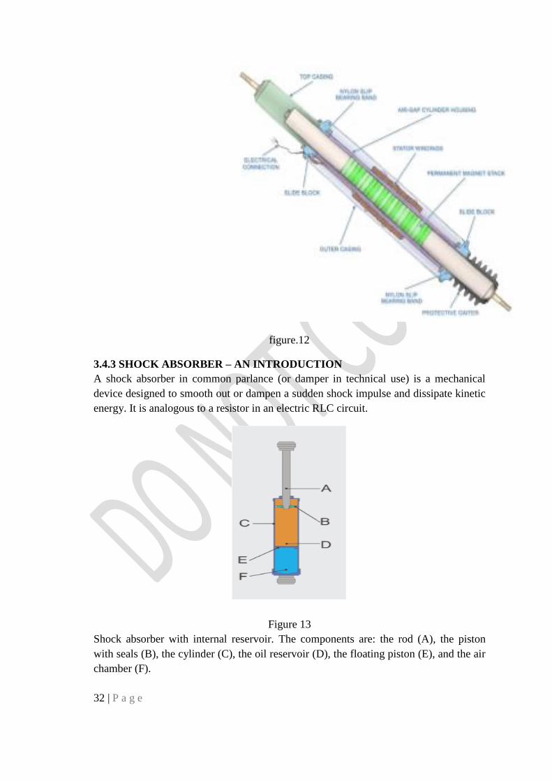
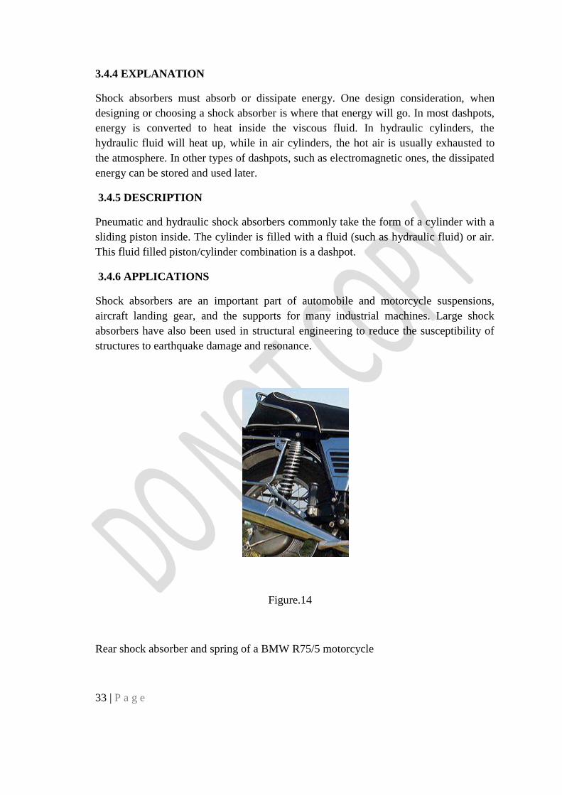
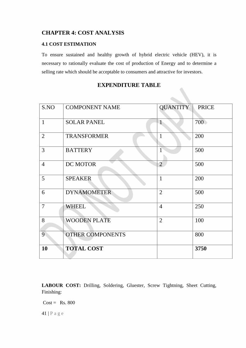