Hybrid Electric Recumbent Motorcycle Powertrain Hybrid Electric Recumbent Motorcycle Powertrain S....
72
2003-05-09-007 Hybrid Electric Recumbent Motorcycle Powertrain S. Koslowsky, J. Nilsen, A. Stuckey Messiah College Engineering Department Final Design Report May 9, 2002 One College Avenue Grantham, PA 17027
Transcript of Hybrid Electric Recumbent Motorcycle Powertrain Hybrid Electric Recumbent Motorcycle Powertrain S....
2003-05-09-007
Hybrid Electric Recumbent
Motorcycle Powertrain
S. Koslowsky, J. Nilsen, A. Stuckey Messiah College Engineering Department
Final Design Report May 9, 2002
One College Avenue Grantham, PA 17027

0.1 Abstract Many automotive manufacturers are actively pursuing hybrid vehicle technology in
an attempt to improve fuel economy and reduce harmful emissions. In response to the need to establish alternative sources of vehicle propulsion, this project has worked in collaboration with Electrion, Inc. to develop a unique personal transportation device utilizing a hybrid electric powertrain. Electrion’s patented design utilizes a drag-reducing recumbent seating position and a hybrid-electric powertrain to increase fuel efficiency.
This project’s efforts focused on designing, constructing, and testing a hybrid-electric powertrain for integration with Electrion’s personal transportation device. The team evaluated various powertrain configurations based on their ability to meet size, weight, and power requirements. The final design combines a four-stroke combustion engine, a DC generator, a lithium polymer battery pack, and a lightweight DC motor in a series configuration. The team tested the powertrain on a dynamometer to simulate real world driving conditions.
0.2 Table of Contents 1 Intro 1.1 Description 1.2 Literature Review 1.3 Solution 2 Design Process 3 Implementation 3.1 Construction 3.1.1 Mounting 3.1.2 Interfacing 3.2 Operation / Testing 3.2.1 Individual Component Testing 3.2.2 Complete Powertrain Testing 4 Project Management 4.1 Gantt Chart 4.2 Explanation 5 Budget 5.1 Proof of Concept 5.2 Prototyping | Production Version 6 Conclusions 6.1 Comparison of Results and Objectives 6.2 Explanation 7 Recommendations for Future Work
0.2 Table of Contents (continued)
8 Appendices 8.1 Actual Design Components
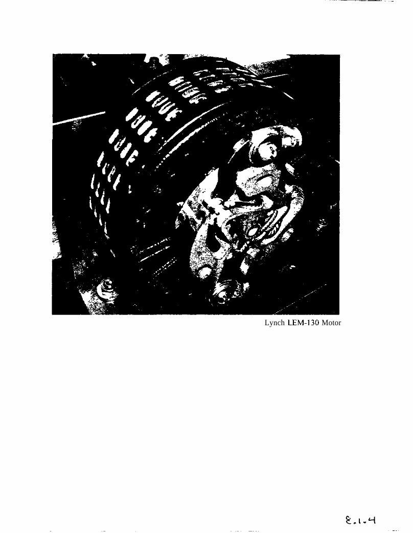
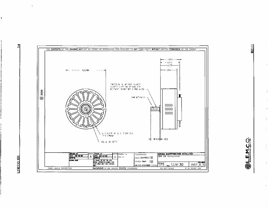
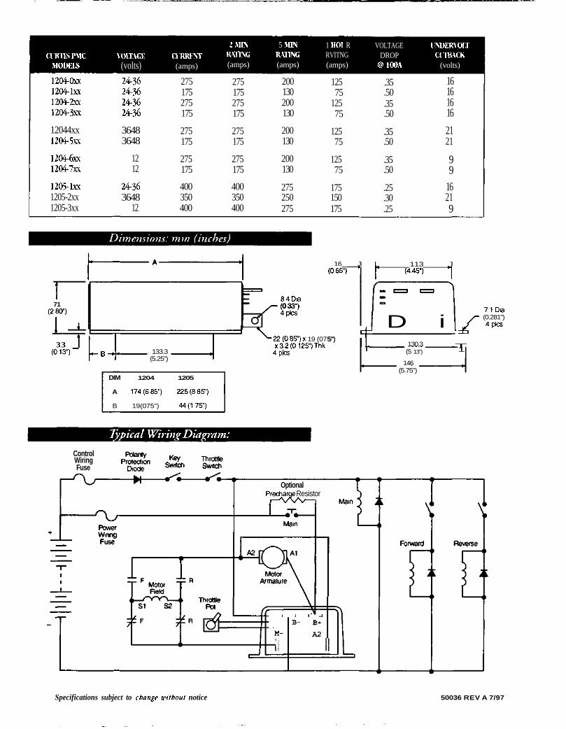
8.1.1 Phase II Frame Design 8.1.2 Honda GX31 Picture and Specifications 8.1.3 Lynch LEM-200 Picture and Specifications 8.1.4 Lynch LEM-130 Picture and Specifications 8.1.5 Curtis 1204 Controller Picture and Specifications 8.1.6 Battery Pack Picture
8.2 Ideal Design Components 8.2.1 Honda GXH50 Picture and Specifications 8.2.2 eCycle MG13D Picture and Specifications 8.2.3 Custom Battery Pack Drawings
8.3 Calculations 8.3.1 Power Calculations 8.3.2 Planetary Gear Calculations 8.3.3 Battery Pack Capacity Calculations 8.3.4 Gear Ratio Calculations
8.4 Construction Drawings and Pictures 8.4.1 Motor and Generator Mounting Brackets 8.4.2 GX31 Fuel Tank Support Bracket 8.4.3 GX31 Sprocket Interface 8.4.4 LEM-200 Sprocket Interface 8.4.5 LEM-130 / Dyno Connecting Shaft 8.4.6 Bearing Support Assembly 8.4.7 Complete Testing Setup 8.4.8 Dynamometer and Data Acquisition Software 8.4.9 “Smart” Throttling Circuitry
8.5 Gantt Chart
9 Bibliography

0.3 Acknowledgements Dr. Donald Pratt – Project Manager
Dr. Timothy Whitmoyer – Project Advisor
Mr. John Meyer – Mechanical and Shop Assistance
Mr. Earl Swope – Electrical Assistance
Dr. Joseph Kejha – Original Hybrid-Electric Recumbent Scooter Design

1 Introduction 1.1 Description
The Hybrid Electric Recumbent Motorcycle Powertrain project is Phase III of an ongoing attempt to design a highly efficient, alternative-fuel personal transportation device. Phase I was completed by pending patent-holder Dr. Joseph Kejha of Electrion, Inc. and dealt with the construction and testing of an initial concept-prototype. A 2001-2002 Messiah College senior engineering design team completed Phase II by redesigning the chassis/frame, steering, and braking systems (see section 8.1.1). This final design report chronicles the achievements of the 2002-2003 Hybrid Electric Recumbent Motorcycle Powertrain team. Essentially, the Hybrid Electric Recumbent Motorcycle Powertrain project successfully completed Phase III by designing and building a high-performance powertrain as a prototype-ready proof of concept for the pending recumbent personal transportation device. Two semesters of engineering research, planning, design, construction and testing, have culminated in the realization of a hybrid powertrain that will be able to meet or exceed the characteristic objectives of a high performance vehicle of this class. This includes being able to cruise at a speed of 40 mph, climb a 5% grade at 35mph for one mile, occupy less than 42.5 liters, and weigh less than 40 kilograms. Additionally, the powertrain can maintain a minimum service interval of greater than 100 hours and is serviceable with standard tools (for a full description of the project’s objectives and performance, please refer to section 6.1.). The powertrain utilizes a cutting edge internal combustion engine, electric generator, DC electric motor and controller, and energy storage device to produce a high-performance propulsion system. The following sections detail the nuances of the powertrain and explain the background, methodology and results of the project. 1.2 Literature Review SIGNIFICANCE OF HYBRID VEHICLE DEVELOPMENT While gasoline combustion engines are the most common driving force behind modern personal transportation, they are also directly related to a host of complex problems. Petroleum-based fuels are a non-renewable resource. In addition, when burned, they emit a mixture of hydrocarbons, nitrogen oxides, carbon monoxide, and carbon dioxide, which ongoing studies link to global warming, ecological, and health-related trends. Furthermore, petroleum product dependence has significant socio-political implications in both intra- and international relations. Thus, hybrid vehicle development strives to preserve natural resources, reduce harmful emissions, and shift our global dependence from petroleum to a combination of better fuel alternatives. Hybrid vehicles are quickly becoming a high performance challenger to the gasoline combustion transportation market. The state of California, along with states like Georgia and New York, is an incredible advocate for alternative transportation fuel solutions. There is a coalition of states under the Federal Department of Energy (DOE) that is working to offer incentives to

consumers for making the switch to more efficient, less emissive hybrid vehicles. Nearly all of the major automotive corporations of the world are matching this shifting paradigm with offerings of hybrid vehicles. At the time of this proposal, consumers can purchase vehicles in a variety of categories, such as ‘friendly’ Neighborhood Electric Vehicles (NEV), ‘forward thinking’ Zero Emissions Vehicles (ZEV), and ‘moderate’ hybrids, which are traditional gasoline or diesel combustion automobiles with electric motor power-assistance. Although most of these vehicles are geared toward urban commuters, many are being developed for short-range suburban use as well (i.e. NEV’s) and, with the right appeal to popular culture, may soon be both economical and practical. CURRENT HYBRID VEHICLE DESIGN
A hybrid powertrain is a system that combines two or more power sources to produce propulsion power. Most major automotive manufacturers, including Honda8, Toyota9, Ford10, and Daimler-Chrysler11, have invested significantly in the research and development of hybrid powertrains. These manufacturers are pursing hybrid technology as a means to provide increased fuel mileage and decreased emissions without sacrificing performance relative to a conventional gasoline-powered vehicle. A hybrid powertrain combines a combustion engine, an electric motor, an electric generator, and a battery pack in one of two basic configurations. In a series hybrid, the combustion engine does not connect directly to the drive wheel. Instead, the engine’s power flows directly to the generator, which converts it into electricity. The generator can then either send the electricity directly to the electric motor to drive the wheel or to the battery pack for storage. Since the drive wheel only receives power from the electric motor, the peak power output of a series hybrid powertrain is limited to the peak power output of its electric motor. As a result, series hybrids typically possess lower peak power output compared to other configurations. However, since the combustion engine in a series hybrid does not connect directly to the drive wheel, the engine is able to operate at its most efficient speed regardless of the vehicle’s speed. This helps increase fuel-efficiency and decrease emissions.12 Additionally, the fact that the engine does not connect directly to the drive wheel in a series hybrid makes the packaging of the powertrain very flexible.
Series hybrid configurations are best suited to small-scale applications, such as one or two person automobiles and motorcycles. Since these applications require efficient use of available space, they benefit from the series configuration’s packaging flexibility. Additionally, since these types of vehicles are very lightweight, they can still possess acceptable performance despite the limited power output of a series configuration.13 In a parallel hybrid, both the combustion engine and the electric motor are mechanically coupled to the drive wheel. This is typically accomplished either by a system of clutches or by a planetary gear set. In a parallel configuration, the power from the combustion engine can flow to either the generator or the drive wheel. Additionally, this configuration permits both the electric motor and the combustion engine to send their power to the drive wheel. Thus, the total power output of a parallel hybrid is equal to the output of the combustion engine plus the output of the electric motor. This essentially allows a parallel hybrid equipped with a smaller, more fuel-efficient combustion engine to offer performance equivalent to a conventional vehicle with a much larger, less fuel-efficient engine.14
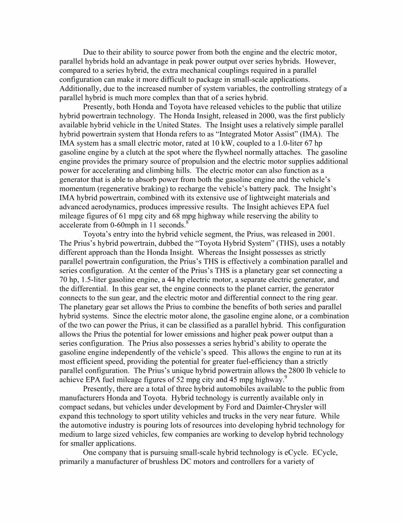
Due to their ability to source power from both the engine and the electric motor, parallel hybrids hold an advantage in peak power output over series hybrids. However, compared to a series hybrid, the extra mechanical couplings required in a parallel configuration can make it more difficult to package in small-scale applications. Additionally, due to the increased number of system variables, the controlling strategy of a parallel hybrid is much more complex than that of a series hybrid. Presently, both Honda and Toyota have released vehicles to the public that utilize hybrid powertrain technology. The Honda Insight, released in 2000, was the first publicly available hybrid vehicle in the United States. The Insight uses a relatively simple parallel hybrid powertrain system that Honda refers to as “Integrated Motor Assist” (IMA). The IMA system has a small electric motor, rated at 10 kW, coupled to a 1.0-liter 67 hp gasoline engine by a clutch at the spot where the flywheel normally attaches. The gasoline engine provides the primary source of propulsion and the electric motor supplies additional power for accelerating and climbing hills. The electric motor can also function as a generator that is able to absorb power from both the gasoline engine and the vehicle’s momentum (regenerative braking) to recharge the vehicle’s battery pack. The Insight’s IMA hybrid powertrain, combined with its extensive use of lightweight materials and advanced aerodynamics, produces impressive results. The Insight achieves EPA fuel mileage figures of 61 mpg city and 68 mpg highway while reserving the ability to accelerate from 0-60mph in 11 seconds.8
Toyota’s entry into the hybrid vehicle segment, the Prius, was released in 2001. The Prius’s hybrid powertrain, dubbed the “Toyota Hybrid System” (THS), uses a notably different approach than the Honda Insight. Whereas the Insight possesses as strictly parallel powertrain configuration, the Prius’s THS is effectively a combination parallel and series configuration. At the center of the Prius’s THS is a planetary gear set connecting a 70 hp, 1.5-liter gasoline engine, a 44 hp electric motor, a separate electric generator, and the differential. In this gear set, the engine connects to the planet carrier, the generator connects to the sun gear, and the electric motor and differential connect to the ring gear. The planetary gear set allows the Prius to combine the benefits of both series and parallel hybrid systems. Since the electric motor alone, the gasoline engine alone, or a combination of the two can power the Prius, it can be classified as a parallel hybrid. This configuration allows the Prius the potential for lower emissions and higher peak power output than a series configuration. The Prius also possesses a series hybrid’s ability to operate the gasoline engine independently of the vehicle’s speed. This allows the engine to run at its most efficient speed, providing the potential for greater fuel-efficiency than a strictly parallel configuration. The Prius’s unique hybrid powertrain allows the 2800 lb vehicle to achieve EPA fuel mileage figures of 52 mpg city and 45 mpg highway.9
Presently, there are a total of three hybrid automobiles available to the public from manufacturers Honda and Toyota. Hybrid technology is currently available only in compact sedans, but vehicles under development by Ford and Daimler-Chrysler will expand this technology to sport utility vehicles and trucks in the very near future. While the automotive industry is pouring lots of resources into developing hybrid technology for medium to large sized vehicles, few companies are working to develop hybrid technology for smaller applications. One company that is pursuing small-scale hybrid technology is eCycle. ECycle, primarily a manufacturer of brushless DC motors and controllers for a variety of
applications, is currently developing a hybrid-powered motorcycle. The eCycle hybrid features a parallel powertrain with an interesting controlling strategy that combines a 219cc diesel engine and an 8 kW electric motor/generator. The engine and motor/generator are directly connected to each other, so they constantly spin at the same speed. When accelerating from a standstill, no fuel is sent to the engine, so the motorcycle only receives power from the electric motor. Once the motorcycle reaches 12mph, the control system begins sending fuel to the engine, and it starts to supply power. When the motorcycle reaches cruising speed, the electric motor no longer supplies power to the motorcycle. Instead, as it spins in sync with the engine, it generates power to recharge the battery pack. If additional power is requested while cruising, the control system will send current to the motor, and it will once again supply power to the motorcycle. eCycle’s hybrid system results in a motorcycle capable of accelerating from zero to sixty in six seconds and reaching an 80 mph top speed while getting achieving 180 mpg.15 REGENERATIVE ENERGY (BRAKING) Regenerative braking is the process of recovering kinetic energy from the moving vehicle during deceleration. It is accomplished by using a traction motor as a generator, which provides braking torque to the wheels and electrical power to the battery pack. On vehicles with large amounts of mass in motion, regenerative braking can recover a significant quantity of energy that would otherwise be lost. However, on smaller vehicles, such as motorcycles and scooters, it is debatable whether the benefits of this process are great enough to justify its incorporation. Additionally, regenerative braking can only be applied to the driven axles. Thus, in a motorcycle, where approximately 70% of the braking power resides at the front axle, regenerative braking can only be applied to the rear axle.16 LITHIUM-ION POLYMER BATTERIES Lithium-ion Polymer batteries are a noteworthy improvement in the realm of battery technology. Traditionally, Lithium-ion (Li-ion) batteries have been the standard for portable and small-cell energy storage. Li-ion polymer batteries are the realization of a new lighter, more adaptable design that maintains and, in some cases, exceeds the performance of Li-ion and Lead-Acid batteries (the latter of which are extremely heavy.) Essentially, Li-ion polymer batteries replace the porous separation layer that needed to be soaked with liquid electrolyte with an extremely thin, flexible polymer membrane that permits ion exchange. This unsaturated polymer membrane eradicates the need for liquid electrolyte in the battery, which greatly simplifies the necessary packaging, and provides incredible design latitude for numerous applications. Instead, a gelled electrolyte increases the ion conductivity. This arrangement provides for greater safety (almost no chance for explosion or leakage), lessened likelihood of overcharging, and a very attractive reduction in weight. Thus, Li-ion polymer batteries offer outstanding potential for revolutionizing devices that require portable charge. This certainly includes the array of hybrid vehicles, which benefit from lessened powertrain weight by requiring less propulsive power.

At the time of this publication, there are at least thirty companies pursuing the production of Li-ion Polymer cells in the United States and around the globe.17 In fact, according to the EETimes Network, the Industry Source for Engineers and Technical Managers Worldwide, “Lithium-ion batteries will displace nickel-metal hydrides (NiMH) as the rechargeable battery of choice in cell phones and personal computers this year, and lithium-polymers are hot on their trail, according to Hideo Takeshita, research vice president of the Institute of Information Technology...”18 Despite advanced coatings that may increase the life-cycle of NiMH cells19, the lithium-ion polymer cells are still showing the most promise for long term utilization. “While 740 million lithium-ion cells were shipped in 2002, lithium-polymer technology offers greater storage capacity and its costs are approaching lithium-ion's, Takeshita said. In addition, lithium-polymer technology can assume compact, oddly-shaped form factors, which helps explain its increased use. Twenty million lithium-polymer cells were used in 2001, increasing to 50 million in 2002, Takeshita said.”18 Lithium-ion polymer cells’ increased safety and ability to assume non-traditional geometries makes them the cutting edge storage solution for all types of lightweight media, including recumbent hybrid vehicles. DC MOTORS In keeping up with the rest of the technological micro-revolution, DC motors are becoming ever lighter, smaller and more powerful. New applications develop daily, demanding higher power for propulsion and motion generation. Developers are meeting the demands of the small-scale design market by designing space and weight-conscious versions of traditional designs. Companies such as eCycle, Incorporated in Temple, PA have met the space and weight demands by designing a lightweight brushless permanent magnet DC motor/generator. It is the self-proclaimed “most efficient and least expensive 5kW motor/generator available,” according to the company website20, generating up to 5kW at only 6kg. Briggs and Stratton licensed the first generation Lynch motor design21 and markets the eTek DC motor, capable of 12hp at 22.3lbs.22 It is a much more powerful motor, but carries a high weight.
The LEMCO (Lynch) LEM-130 DC motor is possibly the most progressive of the brushed permanent magnet DC motors currently available on the consumer market for ultra-lightweight applications. Weighing in at a mere 3kg, it can produce an astonishing maximum of 5hp, more than any other marketed design of comparable weight in its class. The LEM-130 is predominantly utilized in increasingly growing popular “sports” like the United Kingdom’s Robot Wars23. The “sports” consist of individuals or teams building resilient remote-controlled vehicles for various styles of demolition derbies. The LEM-130’s high power-to-weight ratio and rugged, compact design make it an ideal candidate for these applications.24 Similarly, it is becoming the ideal DC motor for a large variety of single-passenger electric and hybrid transportation solutions. There are currently not many end-user market solutions using the LEM-130 available because of its still-too-expensive price tag of ⊥600 ($900 USD). However, it is very commonly identified as the component-of-choice for a vast array of designers who are restricted by small budgets.25 At $900 USD, its speculated performance is only marginally justifiable against its cost, but our comprehensive literature
review indicates that its durability, efficiency and life cycle performance are worth the currently high purchase cost. DC MOTOR CONTROLLERS DC motor controllers supply the electric motor with voltage from the battery packs proportional to the demand indicated by a hybrid vehicle’s throttle. Typically, the throttle is connected to potentiometers, which correlate a mechanical displacement to a resistance, which then correlates to an increased or decreased demand for voltage. The DC motor controller uses that data to transmit the appropriate voltage to the motor. In the motor, this translates to rotational motion for propulsion, where speed is controlled by the voltage input and current regulates torque. The DC motor controller is an integral part of the hybrid powertrain because it regulates the effective speed of the electric motor, transmitting voltage in pulses from the battery pack to the motor. These pulses can be made up to 15,000 times per second, a frequency that makes them ‘silent’ to human ears.26 Effectively, the DC motor controller contributes to making hybrid vehicle operation quieter and is the regulatory brain for the entire electric propulsion system. BRUSHLESS MOTOR/GENERATOR Brushless motors have many advantages over conventional brushed motors, the most obvious being that there are no brushes or commutator. Elimination of the brushes and the commutator increases the overall efficiency of the motor in several ways. First, there is no brush drag against the commutator. This decreases the force acting against the rotation of the rotor, therefore allowing the motor to spin more freely. Second, the life of the motor is greatly increased, as there are no brushes that need to be replaced. This also maintains motor performance over the life of the motor.27
A brushless motor’s construction is much different than that of conventional brushed motors. In most brushed motors, permanent magnets surround the outside of the motor while a rotating electro magnet is in the center. The oppositely charged sides of the central electro magnet and outside permanent magnet are drawn to each other, forcing rotation of the rotor. As the brushes move across the commutator and the oppositely charged magnets draw close to each other, the charge in the central electro magnet is reversed, causing the rotor to continue rotating. This cycle continues and results in continuous motion of the armature. In a brushless motor, the rotor holds the permanent magnets while there are several electro magnets around it. A controller dictates the amount of current that runs through these electro magnets and produces a charge in them. The charge of the electromagnets constantly varies in a rotating fashion. The permanent magnets on the rotor follow this variation in charge, forcing rotation in the rotor. This cycle continues as the controller varies the speed and torque of the motor. Although brushless motor controllers are much more complicated than conventional controllers, they work much more efficiently. The controller must know the position and speed of the motor while supplying power to the correct set of windings to continue a power output.28 Since this is controlled electronically and not physically, the motor is able to run smoother and more efficiently.
MINIATURE FOUR-STROKE COMBUSTION ENGINE
The combustion engine is the overall power source for the entire series hybrid powertrain. The four-stroke combustion engine cycle was invented by Nikolaus Otto in 1867.29 This process converts fuel, through combustion, into translational and rotational motion. In small four-stroke combustion engines, such as those used for generators and pumps, this rotational motion is captured through the output shaft of the engine.
Advancements in compact four-stroke combustion engines have focused on decreasing size and weight while increasing power efficiency. The Honda Motor Company has led the industry of compact four-stroke combustion engines in advancements for the past several years. The 50 cubic centimeter Honda GXH50 engine weighs in at 5.5 kg (12 lbs) and has a peak power output of 1.87 kW (2.5 hp)30 which results in an unparalleled power to weight ratio of 0.34 kW/kg. This engine is “distinguished by its sleeveless uniblock cylinder case, and lightweight single-cam-lobe OHV resin camshaft. The adoption of an aluminum sintered connecting rod, and a highly rigid cover in plastic make this high-speed, high-power four-stroke engine the lightest in its category.”31 No other manufacturer has developed lightweight four-stroke combustion engines that will help us meet the size and weight objectives of this project. 1.3 Solution
Our high-performance hybrid electric powertrain is comprised of the following major components:
- Honda GX31 31cc 4-stroke internal combustion engine (see section 8.1.2) - LEMCO LEM-200 brushed DC generator (see section 8.1.3) - LEMCO LEM-130 brushed 36V DC motor (see section 8.1.4) - Curtis 1204DC motor controller (see section 8.1.5) - Messiah College’s GENESIS award-winning Lithium-ion Polymer battery
packs, modified to create a 36V 60Ah nominal bus (see section 8.1.6)
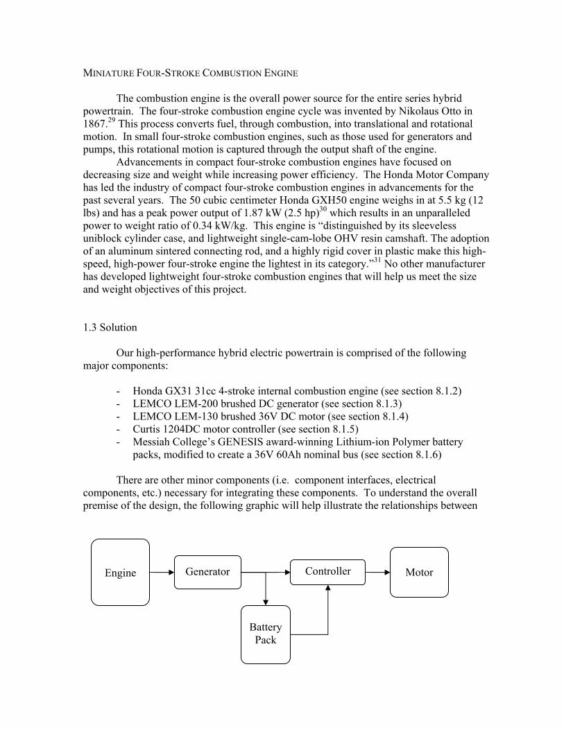
There are other minor components (i.e. component interfaces, electrical components, etc.) necessary for integrating these components. To understand the overall premise of the design, the following graphic will help illustrate the relationships between
Engine
Generator
Battery
Pack
Controller
Motor
the major components. This simplified block diagram of the series hybrid powertrain demonstrates the transfer of power from the combustion engine to the electric motor (which drives the vehicle’s wheels). In our system, as this diagram shows, the combustion engine outputs mechanical power to the generator through an interface consisting of sprockets and a toothed belt. The generator converts this power into electrical energy, and transmits this energy to both the battery pack and controller. Electrical energy from the generator not drawn directly by the controller is stored in the battery pack. The controller sends electrical power to the motor which converts this electrical energy into mechanical energy. The motor’s mechanical energy output can be harnessed to propel the vehicle.
All the components were chosen based on one or more of four guiding principles: minimizing the powertrain’s space (volumetric) requirement, maximizing the power output-to-weight ratio, maximizing efficiency and integrated system response, and making the best use of available resources and allocated funds. Based on these criteria, we deemed the preceding list of components to be the best possible design for this project. There were a number of viable alternatives, including using a Honda GXH50 engine (higher power output, see section 8.2.1), an eCycle brushless DC generator (extended useful life, lower weight, see section 8.2.2), a parallel setup and planetary gear set (higher total energy efficiency), and smaller capacity battery pack (see section 8.2.3). However, based on the essential criteria, each alternative proved inferior to the components used in the final design. The following section continues to explain the work and decision-making that went into developing this lightweight, highly powerful system.
2 Design Process
Before we could begin to design the powertrain we first needed to determine the amount of power it must provide in order to meet our performance objectives. Power requirements were determined for three separate situations. The first situation analyzed the power required for the scooter to overcome aerodynamic drag at cruising speed. The defining parameter in this situation is the product of the coefficient of drag and the frontal area, or CdA. Equations for calculating the power required to overcome aerodynamic drag were sourced from Tamai’s The Leading Edge1 and Dixon’s Tire, Suspension and Handling2. Using these equations and the data given to us by Dr. Kejha from his initial prototype, we extrapolated an approximate value of CdA = 0.3325 for the recumbent scooter. When cruising at 30 mph, Dr. Kejha’s initial prototype required 500W to overcome drag forces. This power requirement of 500W includes aerodynamic drag forces, frictional forces in the drivetrain, and rolling frictional forces. It should also be noted that this power requirement was the power input to the electric motor, not the power output by the motor. Since the electric motor on Dr. Kejha’s initial prototype could not have been operating at a perfect 100% efficiency, the actual power output requirement would be slightly lower. This calculation treated the frictional forces present in Dr. Kejha’s initial prototype as one in the same with the aerodynamic drag forces. However, frictional forces increase linearly with velocity, but aerodynamic drag forces increase with the cube of velocity. This causes our calculation to overestimate the effects of the frictional forces, thus providing a conservative estimate of the required power. Using this method, we calculated the power required to overcome drag forces at a cruising speed of 40 mph to be 1.2 kW (see section 8.3.1). Next, we analyzed the power required to be able to meet our objective of climbing a 5% grade at 35 mph. The total power required to meet this objective is the sum of the power required to overcome drag forces at the desired speed of 35 mph and the power required to overcome gravity and produce the vertical velocity component needed to climb the hill. This calculation showed that we would need 2.1 kW to meet the hill climb objective (see section 8.3.1). Finally, we also analyzed was the power required to meet our acceleration objective of zero to 35mph in 8 seconds. This was found by calculating the sum of the power required to produce the desired rate of acceleration and the average power required to overcome drag forces. Applying this method, we determined that the acceleration objective requires 2.6 kW (see section 8.3.1). After determining the power requirements for the powertrain, the next critical design decision that our team needed to make was the choice to use either a series or a parallel powertrain system. In a series hybrid system, there is no direct mechanical connection between the combustion engine and the driven wheel. Instead, the engine is used solely for powering the generator. The electricity produced by the generator can then either be stored in the battery pack or sent directly to the motor to drive the wheel. Parallel hybrid systems operate in a similar manner, but can also send the power from the combustion engine directly to the driven wheel. In addition to performing background research on series and parallel hybrid systems, both systems were also modeled using a program called HEVA to learn about their basic characteristics3. Hybrid-Electric Vehicle Analysis (HEVA) is a program
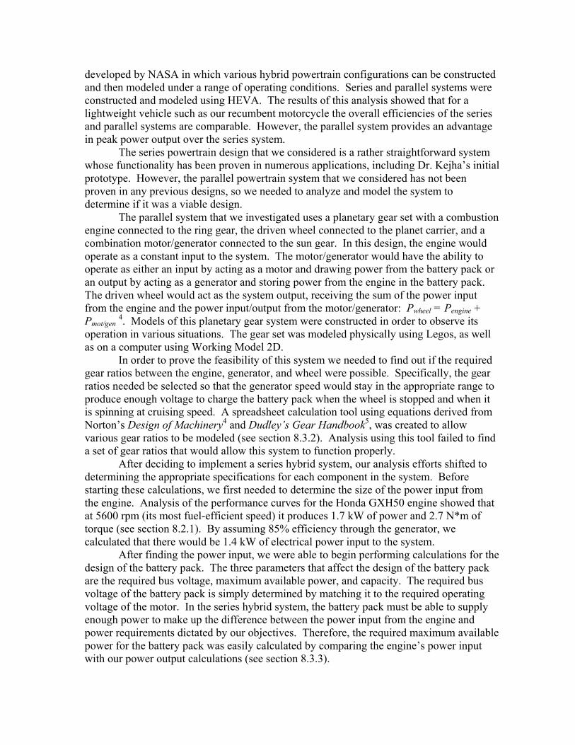
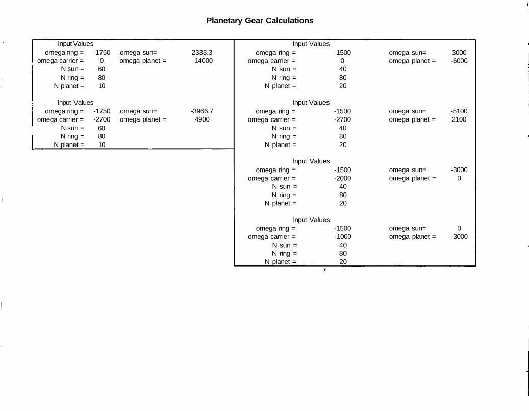
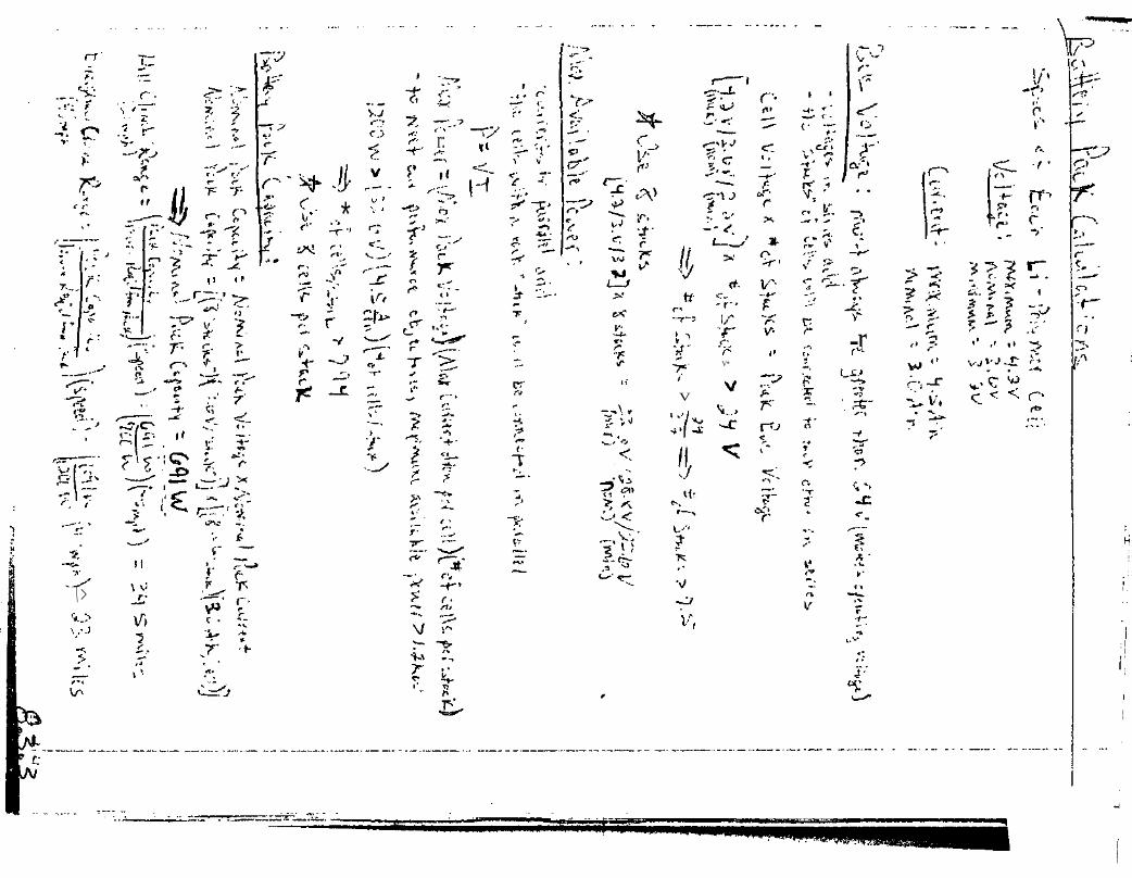
developed by NASA in which various hybrid powertrain configurations can be constructed and then modeled under a range of operating conditions. Series and parallel systems were constructed and modeled using HEVA. The results of this analysis showed that for a lightweight vehicle such as our recumbent motorcycle the overall efficiencies of the series and parallel systems are comparable. However, the parallel system provides an advantage in peak power output over the series system. The series powertrain design that we considered is a rather straightforward system whose functionality has been proven in numerous applications, including Dr. Kejha’s initial prototype. However, the parallel powertrain system that we considered has not been proven in any previous designs, so we needed to analyze and model the system to determine if it was a viable design. The parallel system that we investigated uses a planetary gear set with a combustion engine connected to the ring gear, the driven wheel connected to the planet carrier, and a combination motor/generator connected to the sun gear. In this design, the engine would operate as a constant input to the system. The motor/generator would have the ability to operate as either an input by acting as a motor and drawing power from the battery pack or an output by acting as a generator and storing power from the engine in the battery pack. The driven wheel would act as the system output, receiving the sum of the power input from the engine and the power input/output from the motor/generator: Pwheel = Pengine + Pmot/gen 4. Models of this planetary gear system were constructed in order to observe its operation in various situations. The gear set was modeled physically using Legos, as well as on a computer using Working Model 2D. In order to prove the feasibility of this system we needed to find out if the required gear ratios between the engine, generator, and wheel were possible. Specifically, the gear ratios needed be selected so that the generator speed would stay in the appropriate range to produce enough voltage to charge the battery pack when the wheel is stopped and when it is spinning at cruising speed. A spreadsheet calculation tool using equations derived from Norton’s Design of Machinery4 and Dudley’s Gear Handbook5, was created to allow various gear ratios to be modeled (see section 8.3.2). Analysis using this tool failed to find a set of gear ratios that would allow this system to function properly. After deciding to implement a series hybrid system, our analysis efforts shifted to determining the appropriate specifications for each component in the system. Before starting these calculations, we first needed to determine the size of the power input from the engine. Analysis of the performance curves for the Honda GXH50 engine showed that at 5600 rpm (its most fuel-efficient speed) it produces 1.7 kW of power and 2.7 N*m of torque (see section 8.2.1). By assuming 85% efficiency through the generator, we calculated that there would be 1.4 kW of electrical power input to the system. After finding the power input, we were able to begin performing calculations for the design of the battery pack. The three parameters that affect the design of the battery pack are the required bus voltage, maximum available power, and capacity. The required bus voltage of the battery pack is simply determined by matching it to the required operating voltage of the motor. In the series hybrid system, the battery pack must be able to supply enough power to make up the difference between the power input from the engine and power requirements dictated by our objectives. Therefore, the required maximum available power for the battery pack was easily calculated by comparing the engine’s power input with our power output calculations (see section 8.3.3).
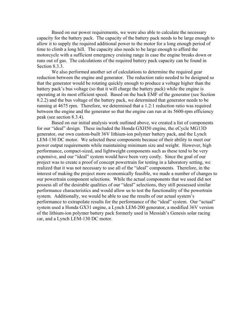
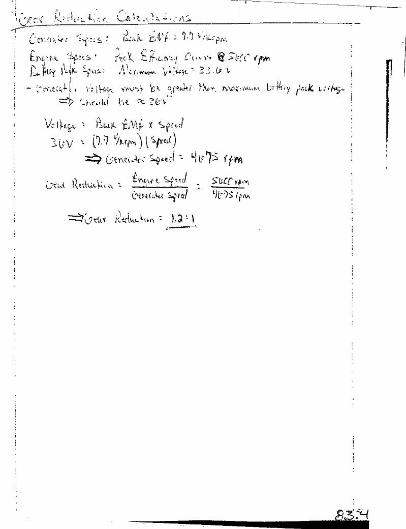
Based on our power requirements, we were also able to calculate the necessary capacity for the battery pack. The capacity of the battery pack needs to be large enough to allow it to supply the required additional power to the motor for a long enough period of time to climb a long hill. The capacity also needs to be large enough to afford the motorcycle with a sufficient emergency cruising range in case the engine breaks down or runs out of gas. The calculations of the required battery pack capacity can be found in Section 8.3.3. We also performed another set of calculations to determine the required gear reduction between the engine and generator. The reduction ratio needed to be designed so that the generator would be rotating quickly enough to produce a voltage higher than the battery pack’s bus voltage (so that it will charge the battery pack) while the engine is operating at its most efficient speed. Based on the back EMF of the generator (see Section 8.2.2) and the bus voltage of the battery pack, we determined that generator needs to be running at 4675 rpm. Therefore, we determined that a 1.2:1 reduction ratio was required between the engine and the generator so that the engine can run at its 5600-rpm efficiency peak (see section 8.3.4). Based on our initial analysis work outlined above, we created a list of components for our “ideal” design. These included the Honda GXH50 engine, the eCycle MG13D generator, our own custom-built 36V lithium-ion polymer battery pack, and the Lynch LEM-130 DC motor. We selected these components because of their ability to meet our power output requirements while maintaining minimum size and weight. However, high performance, compact-sized, and lightweight components such as these tend to be very expensive, and our “ideal” system would have been very costly. Since the goal of our project was to create a proof of concept powertrain for testing in a laboratory setting, we realized that it was not necessary to use all of the “ideal” components. Therefore, in the interest of making the project more economically feasible, we made a number of changes to our powertrain component selections. While the actual components that we used did not possess all of the desirable qualities of our “ideal” selections, they still possessed similar performance characteristics and would allow us to test the functionality of the powertrain system. Additionally, we would be able to use the results of our actual system’s performance to extrapolate results for the performance of the “ideal” system. Our “actual” system used a Honda GX31 engine, a Lynch LEM-200 generator, a modified 36V version of the lithium-ion polymer battery pack formerly used in Messiah’s Genesis solar racing car, and a Lynch LEM-130 DC motor.

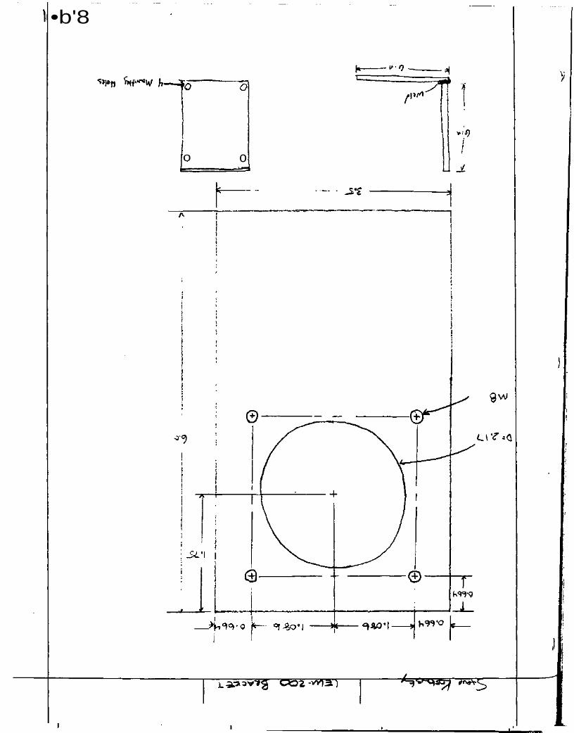
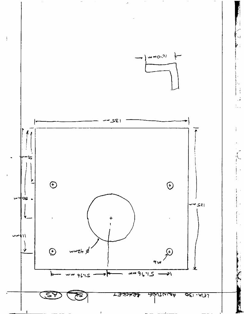
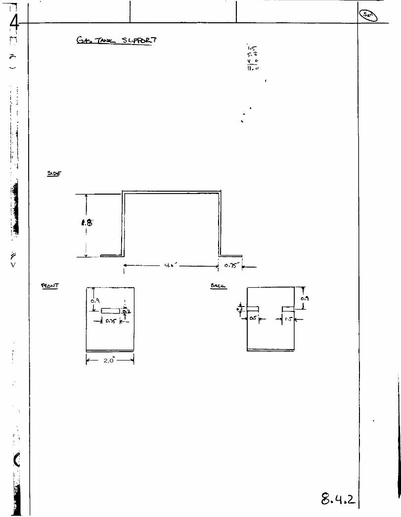
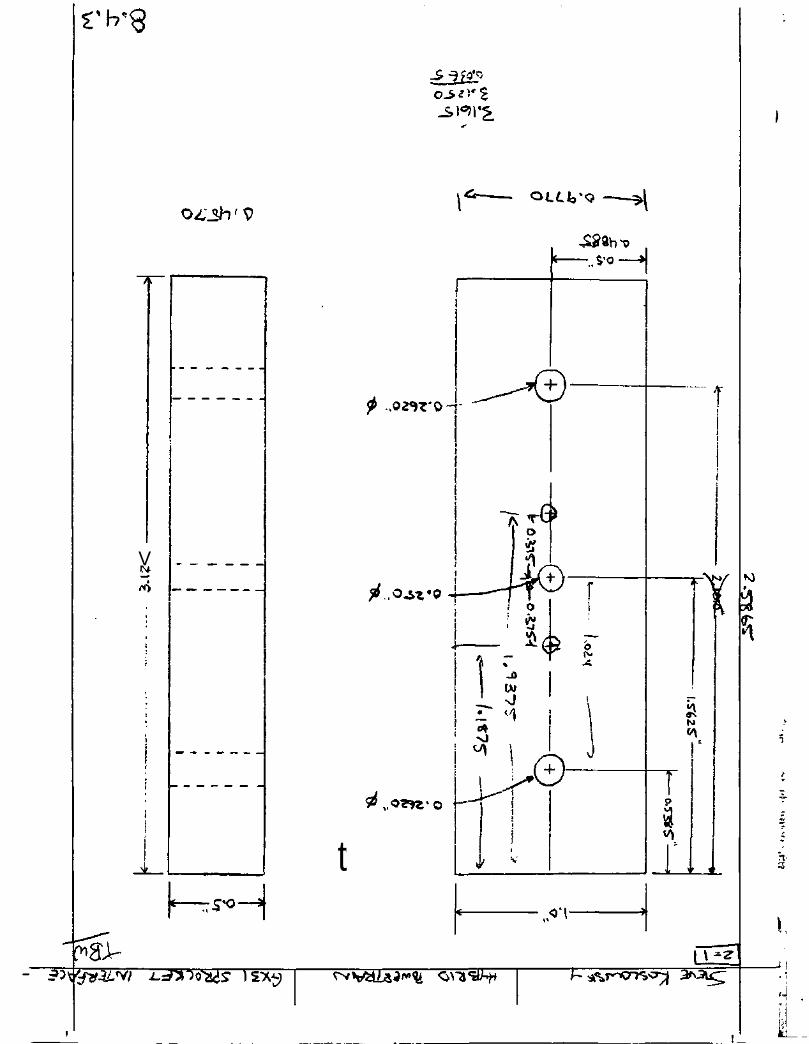
3. Implementation 3.1 Construction 3.1.1 Mounting The first step in the construction of the hybrid electric powertrain test bench setup was creating the mounting devices to attach the components to the test bench. For the Lynch LEM-200 generator and the Lynch LEM-130 motor, sturdy brackets were constructed to securely fasten the components to the test bench. Each bracket consisted of two plates of mild steel welded together perpendicularly. The vertical plate had precision holes drilled to match the mounting holes on the respective component, while the horizontal plate had four drilled holes to allow for secure mounting to the test bench (see section 8.4.1). The horizontal mounting holes were re-designed, after initial construction, to allow a small amount of movement of the mounting bracket. This allowed for small adjustments for proper alignment when interfacing all of the components together. For the Honda GX31 engine, a different approach was taken. Four mounting holes were drilled and tapped in the base of the engine to allow for mounting to the test bench with vertical bolts. Since the gasoline tank extended below the mounting holes on the case of the engine, spacers were machined to prevent adverse loading of the tank and to allow for secure mounting. After initial testing, it was realized that the vibration of the engine was greater than expected. This vibration posed a threat to the other components on the test bench, so to remedy the problem, rubber damping washers were added underneath the spacers. These washers greatly reduced the transmission of the vibration from the engine to the test bench, thus reducing the threat to other components. As a result, the gasoline tank was removed from underneath the engine and mounted directly to the test bench with a mounting bracket (see section 8.4.2). 3.1.2 Interfacing The next step in the construction of the hybrid electric powertrain test bench setup was creating the engine/ generator and the motor/ dynamometer interfaces. This proved to be the most time consuming task in the entire construction process. The Honda GX31 engine is specifically designed to utilize a centrifugal clutch to output power. Since we designed to attach a sprocket directly to the engine, we needed a coupling device to bridge the existing clutch mounting holes on the engine which would then allow a sprocket to be centered on the crankshaft power take-off. Since the maximum power output of the engine corresponds with 7000 RPM, this coupling device needed to have very tight tolerances to minimize any vibration at this high rotational speed. A piece of rectangular stock aluminum was machined to ensure near perfect symmetry. The mounting holes for the engine and sprocket were precisely drilled to guarantee that the sprocket would be centered on the engine crankshaft power take-off (see section 8.4.3). Mounting holes were also drilled in the sprocket to allow for correct alignment and mounting to the coupling bar.
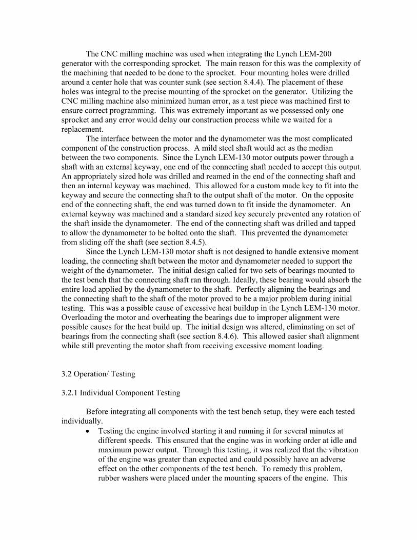
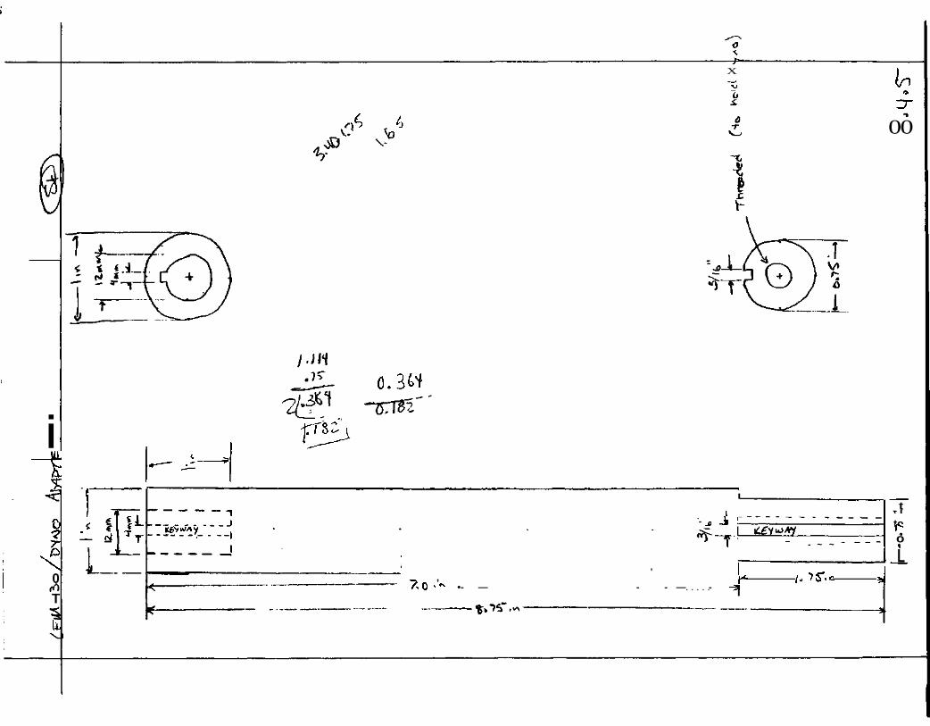
The CNC milling machine was used when integrating the Lynch LEM-200 generator with the corresponding sprocket. The main reason for this was the complexity of the machining that needed to be done to the sprocket. Four mounting holes were drilled around a center hole that was counter sunk (see section 8.4.4). The placement of these holes was integral to the precise mounting of the sprocket on the generator. Utilizing the CNC milling machine also minimized human error, as a test piece was machined first to ensure correct programming. This was extremely important as we possessed only one sprocket and any error would delay our construction process while we waited for a replacement. The interface between the motor and the dynamometer was the most complicated component of the construction process. A mild steel shaft would act as the median between the two components. Since the Lynch LEM-130 motor outputs power through a shaft with an external keyway, one end of the connecting shaft needed to accept this output. An appropriately sized hole was drilled and reamed in the end of the connecting shaft and then an internal keyway was machined. This allowed for a custom made key to fit into the keyway and secure the connecting shaft to the output shaft of the motor. On the opposite end of the connecting shaft, the end was turned down to fit inside the dynamometer. An external keyway was machined and a standard sized key securely prevented any rotation of the shaft inside the dynamometer. The end of the connecting shaft was drilled and tapped to allow the dynamometer to be bolted onto the shaft. This prevented the dynamometer from sliding off the shaft (see section 8.4.5). Since the Lynch LEM-130 motor shaft is not designed to handle extensive moment loading, the connecting shaft between the motor and dynamometer needed to support the weight of the dynamometer. The initial design called for two sets of bearings mounted to the test bench that the connecting shaft ran through. Ideally, these bearing would absorb the entire load applied by the dynamometer to the shaft. Perfectly aligning the bearings and the connecting shaft to the shaft of the motor proved to be a major problem during initial testing. This was a possible cause of excessive heat buildup in the Lynch LEM-130 motor. Overloading the motor and overheating the bearings due to improper alignment were possible causes for the heat build up. The initial design was altered, eliminating on set of bearings from the connecting shaft (see section 8.4.6). This allowed easier shaft alignment while still preventing the motor shaft from receiving excessive moment loading. 3.2 Operation/ Testing 3.2.1 Individual Component Testing Before integrating all components with the test bench setup, they were each tested individually.
• Testing the engine involved starting it and running it for several minutes at different speeds. This ensured that the engine was in working order at idle and maximum power output. Through this testing, it was realized that the vibration of the engine was greater than expected and could possibly have an adverse effect on the other components of the test bench. To remedy this problem, rubber washers were placed under the mounting spacers of the engine. This
greatly reduced the transmission of the vibration from the engine to the test bench.
• Proper alignment of the toothed belt between the engine and generator was critical in order to prevent the belt from coming off the sprockets. The engine and generator were visually aligned and spaced to allow proper belt tension. The engine was then run at low speed to ensure the belt alignment and tension were correct.
• The generator output was tested utilizing a variable resistor bank to apply a load to the generator. Both the current and voltage output at different loads were recorded and analyzed to determine the output and efficiency of the generator when run by the Honda GX31 engine.
• Each of the individual stacks of battery cells in the battery pack were tested for both usage and recovery. The stacks were initially charged to full capacity and then discharged through a variable resistor bank. This verified the integrity of the cells.
• The motor was tested along with the controller and throttle. This ensured proper communication and response time between the three components.
• The dynamometer and acquisition software were tested to ensure proper setup and communication.
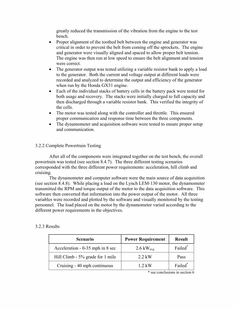
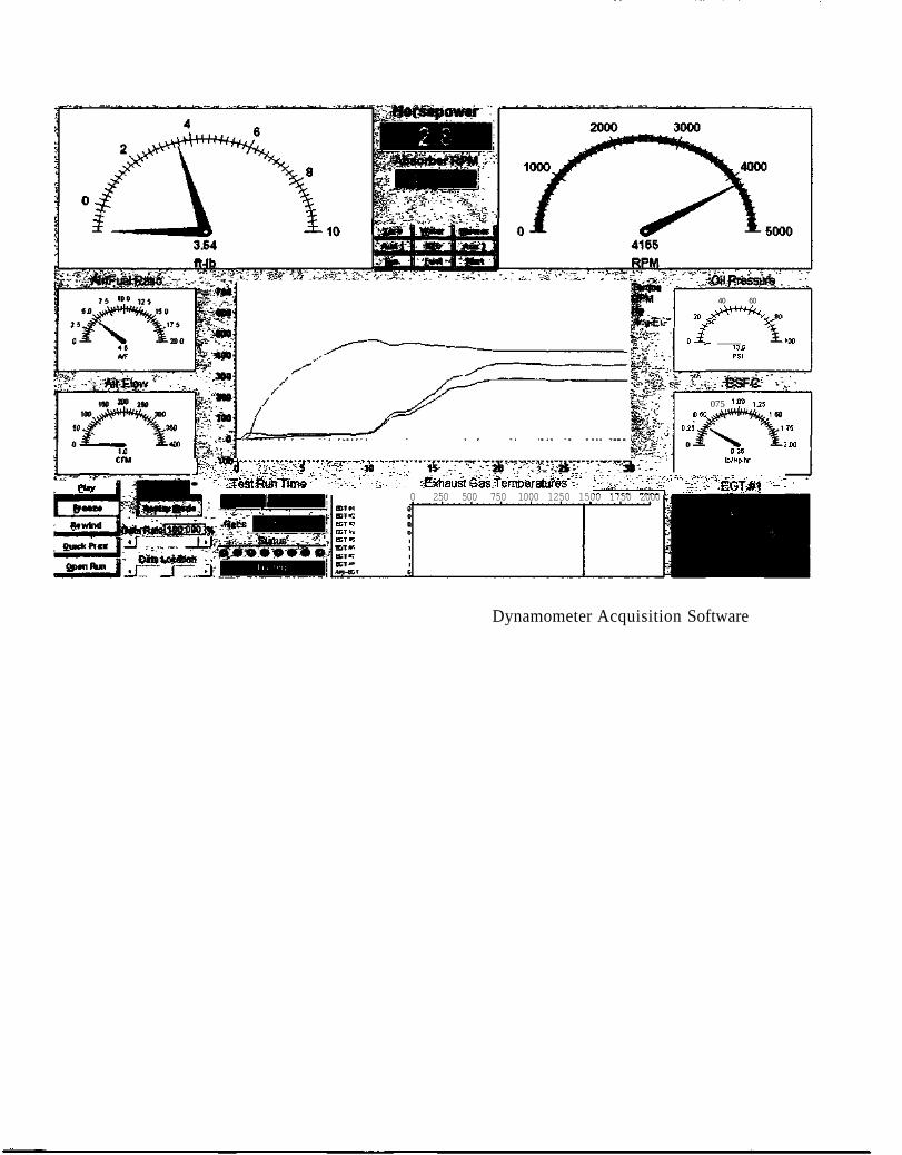
3.2.2 Complete Powertrain Testing After all of the components were integrated together on the test bench, the overall powertrain was tested (see section 8.4.7). The three different testing scenarios corresponded with the three different power requirements: acceleration, hill climb and cruising. The dynamometer and computer software were the main source of data acquisition (see section 8.4.8). While placing a load on the Lynch LEM-130 motor, the dynamometer transmitted the RPM and torque output of the motor to the data acquisition software. This software then converted that information into the power output of the motor. All three variables were recorded and plotted by the software and visually monitored by the testing personnel. The load placed on the motor by the dynamometer varied according to the different power requirements in the objectives. 3.2.3 Results
Scenario Power Requirement Result
Acceleration - 0-35 mph in 8 sec 2.6 kWavg Failed*
Hill Climb - 5% grade for 1 mile 2.2 kW Pass
Cruising - 40 mph continuous 1.2 kW Failed*
* see conclusions in section 6
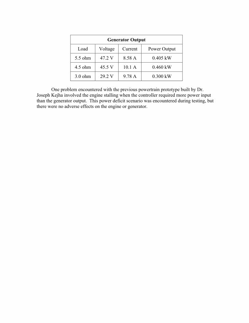
Generator Output
Load Voltage Current Power Output
5.5 ohm 47.2 V 8.58 A 0.405 kW
4.5 ohm 45.5 V 10.1 A 0.460 kW
3.0 ohm 29.2 V 9.78 A 0.300 kW One problem encountered with the previous powertrain prototype built by Dr.
Joseph Kejha involved the engine stalling when the controller required more power input than the generator output. This power deficit scenario was encountered during testing, but there were no adverse effects on the engine or generator.

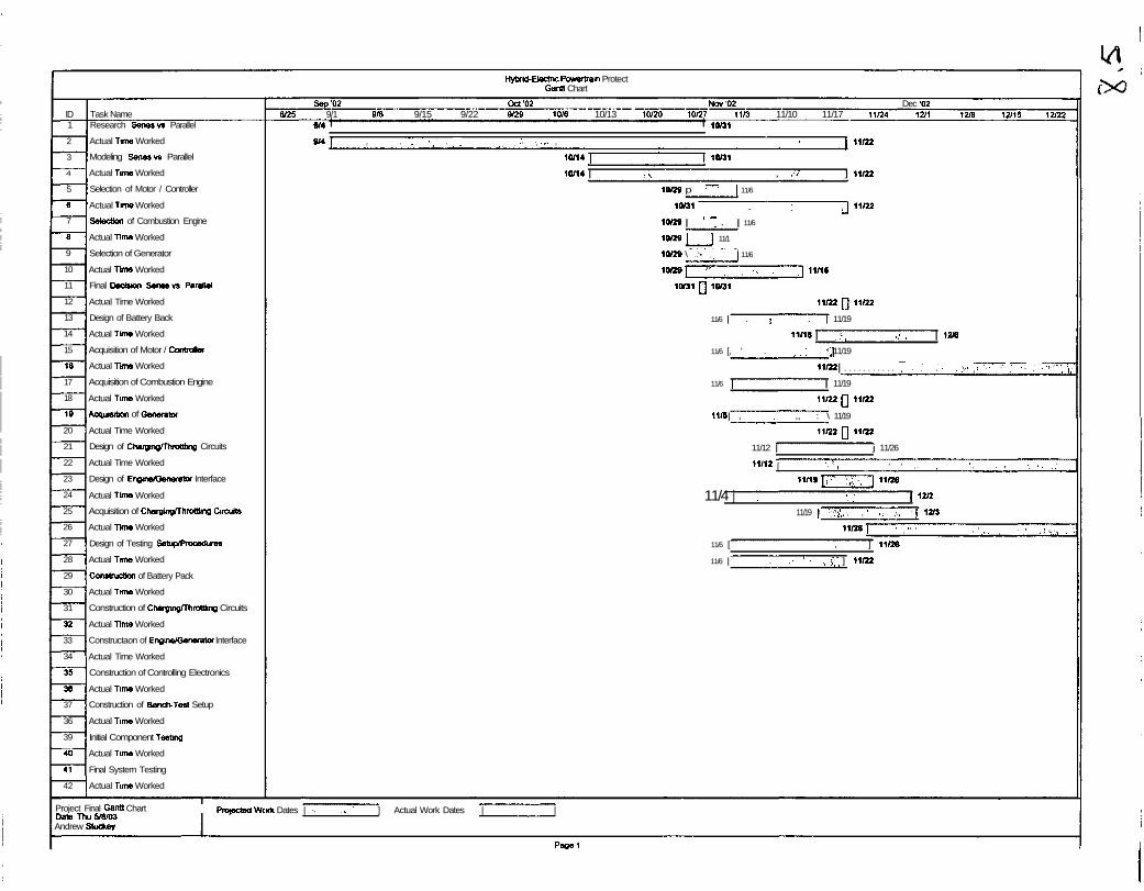
4 Project Management 4.1 Gantt Chart
See Section 8.5 4.2 Explanation
The tasks scheduled for this project essentially fell into four categories: design, acquisition, construction, and testing. One of the more problematic areas for our scheduling was parts acquisition. This was partially due to minor setbacks in the completion of our initial design and selection of the required components, which delayed the ordering process. Additionally, we had not anticipated such a lengthy delivery time for the LEM-130 motor. The setbacks that we experienced in parts acquisition in turn caused delays in our construction and testing tasks. Furthermore, we underestimated the time required for the construction of the engine/generator interface and the bench testing setup. Finally, our schedule was also affected by a late start in the spring semester due to the fact that none of the three team members were on campus during J-term. Despite these setbacks, we were able to finish the required tasks by the end of the semester through a combination of hard work, long hours, and teamwork.
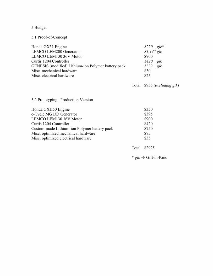
5 Budget 5.1 Proof-of-Concept Honda GX31 Engine $220 gik* LEMCO LEM200 Generator $1,145 gik LEMCO LEM130 36V Motor $900 Curtis 1204 Controller $420 gik GENESIS (modified) Lithium-ion Polymer battery pack $??? gik Misc. mechanical hardware $30 Misc. electrical hardware $25 Total $955 (excluding gik) 5.2 Prototyping | Production Version Honda GXH50 Engine $350 e-Cycle MG13D Generator $395 LEMCO LEM130 36V Motor $900 Curtis 1204 Controller $420 Custom-made Lithium-ion Polymer battery pack $750 Misc. optimized mechanical hardware $75 Misc. optimized electrical hardware $35 Total $2925 * gik Gift-in-Kind
6 Conclusions 6.1 Comparison of Results and Objectives
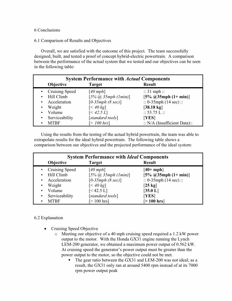
Overall, we are satisfied with the outcome of this project. The team successfully designed, built, and tested a proof of concept hybrid-electric powertrain. A comparison between the performance of the actual system that we tested and our objectives can be seen in the following table:
System Performance with Actual Components Objective Target Result
• Cruising Speed [40 mph] :: 31 mph :: • Hill Climb [5% @ 35mph (1min)] [5% @35mph (1+ min)] • Acceleration [0-35mph (8 sec)] :: 0-35mph (14 sec) :: • Weight [< 40 kg] [38.18 kg] • Volume [< 42.5 L] :: 53.75 L :: • Serviceability [standard tools] [YES] • MTBF [> 100 hrs] :: N/A (Insufficient Data)::
Using the results from the testing of the actual hybrid powertrain, the team was able to
extrapolate results for the ideal hybrid powertrain. The following table shows a comparison between our objectives and the projected performance of the ideal system:
System Performance with Ideal Components Objective Target Result
• Cruising Speed [40 mph] [40+ mph] • Hill Climb [5% @ 35mph (1min)] [5% @35mph (1+ min)] • Acceleration [0-35mph (8 sec)] :: 0-35mph (14 sec) :: • Weight [< 40 kg] [25 kg] • Volume [< 42.5 L] [35.0 L] • Serviceability [standard tools] [YES] • MTBF [> 100 hrs] [> 100 hrs]
6.2 Explanation
• Cruising Speed Objective o Meeting our objective of a 40 mph cruising speed required a 1.2 kW power
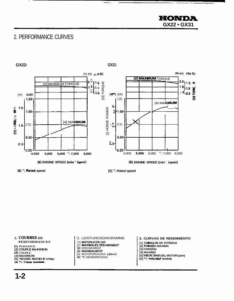
output to the motor. With the Honda GX31 engine running the Lynch LEM-200 generator, we obtained a maximum power output of 0.562 kW. At cruising speed the generator’s power output must be greater than the power output to the motor, so the objective could not be met.
The gear ratio between the GX31 and LEM-200 was not ideal; as a result, the GX31 only ran at around 5400 rpm instead of at its 7000 rpm power output peak
• At 5400 rpm the GX31’s power output is only 0.82 kW By using the more powerful Honda GXH50 engine (1.85 kW peak
output) and a gear ratio that would allow it to run at its optimal speed, the power output by the generator would be 1.4 kW (thus meeting the cruising speed objective)
• Acceleration Objective:
o Our 0-35 mph in 8 seconds acceleration objective required an average power output of 2.6 kW. While the battery pack and generator were capable of supplying this much power, the LEM-130 motor would not be able to handle the high current involved in this operation (it has a 5 second maximum current rating of 120A)
While the LEM-130 is capable of power outputs much greater than this 2.6 kW requirement, it cannot provide this much power at low speeds due to its current limitation
One way to solve this problem would be to use a transmission (such as the continuously variable transmissions used on snowmobiles) that would always allow the motor to operate at a high speed where it would draw less current
• Volume Objective
o Our actual system failed to meet the 40 L volume objective primarily due to the size of the battery pack that we used.
Using a custom-sized battery pack (such as the one we initially designed to use, see section 8.2.3), this objective could easily be met
• MTBF Objective
o Since we did not have the opportunity to conduct extensive testing, we were unable to verify that our system possessed a MTBF >100 hours.
Additionally, we did not have sufficient information from all of the component suppliers to allow us to make a satisfactory estimate of the system’s MTBF

7 Future Work
• Use ideal components o Honda GHX50 2.5 hp engine o e-Cycle MG13D brushless generator o Appropriately sized battery pack
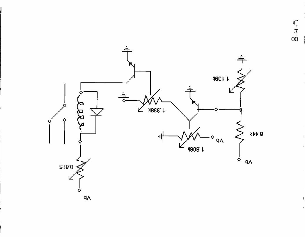
• Create an automated control system o ‘Smart’ throttle to control current draw (see section 8.4.9) o Charge / discharge protection
• Design and construct a user interface o Create dashboard display ready for integration with final frame design o Display system information (voltage, current, power output, etc)
• Improve ergonomics • Automate engine throttle with linear actuator • Integrate powertrain with final frame design • Implement a transmission to allow the motor to run at optimal speeds and
provide satisfactory acceleration performance
9 Bibliography
1. Tamai, Goro. The Leading Edge: aerodynamic design of ultra-streamlines land vehicles. Cambridge, MA: Robert Bentley Publishers, 1999.
2. Dixon, John C. Tires, Suspension and Handling. 2nd Ed. Cambridge, UK:
Cambridge University Press, 1996. 3. http://space-power.grc.nasa.gov/ppo/projects/heva/index.html 4. Norton, Robert L. Design of Machinery. 2nd Ed. New York, NY:
McGraw-Hill, 2001. 5. Dudley, Darle W. Dudley’s Gear Handbook. Revised 1st Ed. New York,
NY: McGraw-Hill, 1991. 6. “Technical Document: Lithium Polymer Cell Performance- SLB 526495
Type, 043-07000-SPC-006.” http://www.worley.com.au/wecs 7. “QuickView Data Sheet: MAX4373/MAX4374/ MAX4375.”
http://www.maxim-ic.com/quick_view2.cfm?qv_pk=2204. 8. www.hondacars.com 9. www.toyota.com 10. www.hybridford.com 11. www.dcx.com 12. “Technology for Electric and Hybrid Vehicles: SP-1331.” P133-136.
Society of Automotive Engineers, 1998.
13. Hirt, Andreas. “City Slicker.” Electric and Hybrid Vehicle Technology
International, Annual Review 2000. P38-40.
14. www.howstuffworks.com/hybrid-car.htm 15. http://www.ecycle.com/powersports/hybrid.htm 16. “Electric and Hybrid Electric Vehicles and Fuel Cell Technology: SP-
1466.” P25-29. Society of Automotive Engineers, 1999.
17. “Source Guides: Renewable Energy,” http://energy.sourceguides.com/businesses/byP/batP/batt/btora/bType/lipoly/byB/mfg/mfg.shtml
18. Ohr, Stephan. “Lithium-polymer batteries find favor in cell phones.”
EETimes Magazine, October 2002. http://www.eetimes.com/sys/news/OEG20021001S0062
19. McGrath, Don. “Thin film coating holds promise to hydrogen storage and
better batteries.” EV News, February 2001. 20. http://www.ecycle.com/motorgenerator/default.htm 21. Shiely, Vince. “Briggs& Stratton’s Search for Modern DC Motor
Technology Leads to Success.” Industrial Utility Vehicle & Mobile Equipment, July/August 2001.
22. http://www.briggsandstratton.com/MainSite.asp?CategoryID=289&lrID=1
&ParentID=289&MSCSSID=1234&MB=&EPAGE=/main/RealBriggs/WebSite/NA/EN/new_products/etek.mb&l=0
23. http://www.robotwars.co.uk/ 24. http://home.btclick.com/m.phillipson/Robots/DisConstructorMain.htm 25. http://cb1.com/~lkcl/SpiderBot/design/) 26. http://www.howstuffworks.com/electric-car2.htm 27. http://www.aveox.com/faq.html 28. http://www.alansmodels.com/engines/how_motor_brushless.htm 29. http://www.spartacus.schoolnet.co.uk/SCotto.htm 30. http://www.honda-engines.com/gxframe.htm 31. http://world.honda.com/news/1998/p980629a.html

9 Appendices
Phase I I Frame dcsian
S . l . V
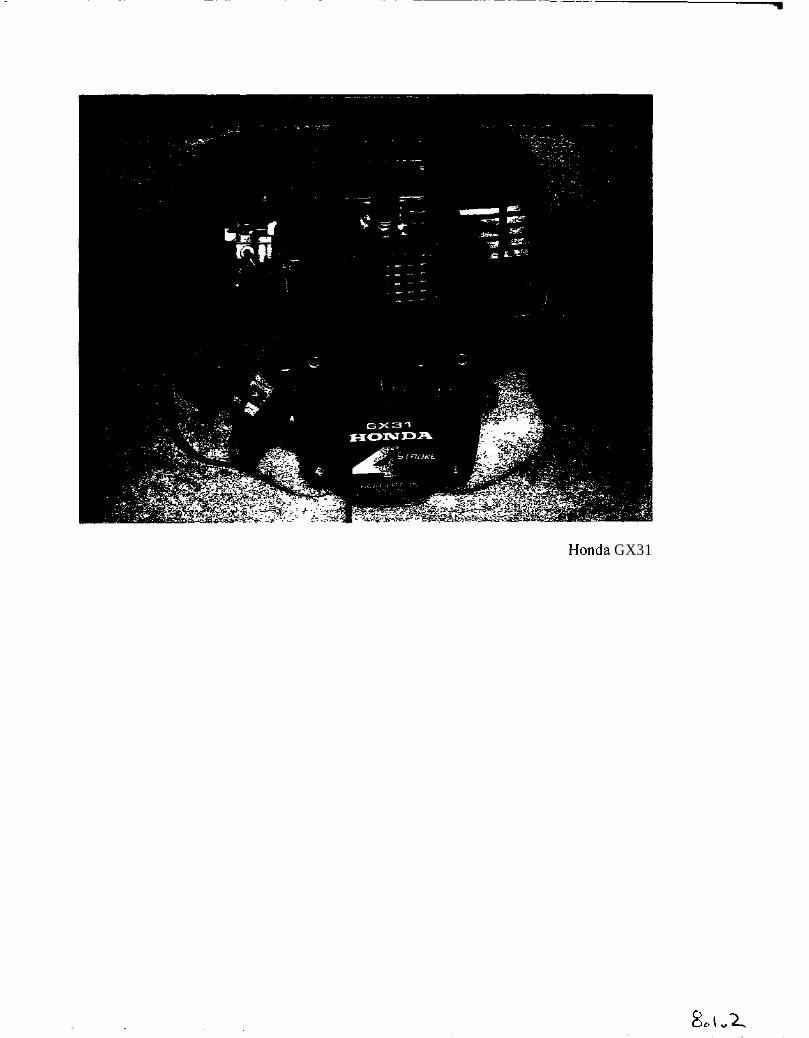
Honda GX31
8*1
1. SPECIFICATIONS GX22 • GX31
1. SPECIFICATIONS2. PERFORMANCE CURVES
3. DIMENSIONAL DRAWINGS
1. SPECIFICATIONS• ENGINE
Model
Description code
Type
Displacement
Bore x stroke
Maximum horsepower
Maximum torque
Compression ratio
Fuel comsumption
Cooling system
Ignition system
Ignition timing
Spark plug
Carburetor
Air cleaner
Lubrication system
Oil capacity
Starting system
Stopping system
Fuel used
Fuel tank capacity
PTO shaft rotation
GX22
GCAF
GX31GCAG
4-stroke, overhead valve single cylinder
22 cm'(1.3cu-in)
33 x 26 mm (1.3 x 1.0 in)
0.74 kW (1.0 HP) at 7,000 min -1 (rpm)
1.09 N-m (0.11 kgf-m. 0.80 Ibf-ft)at 4.500 mm"1 (rpm)
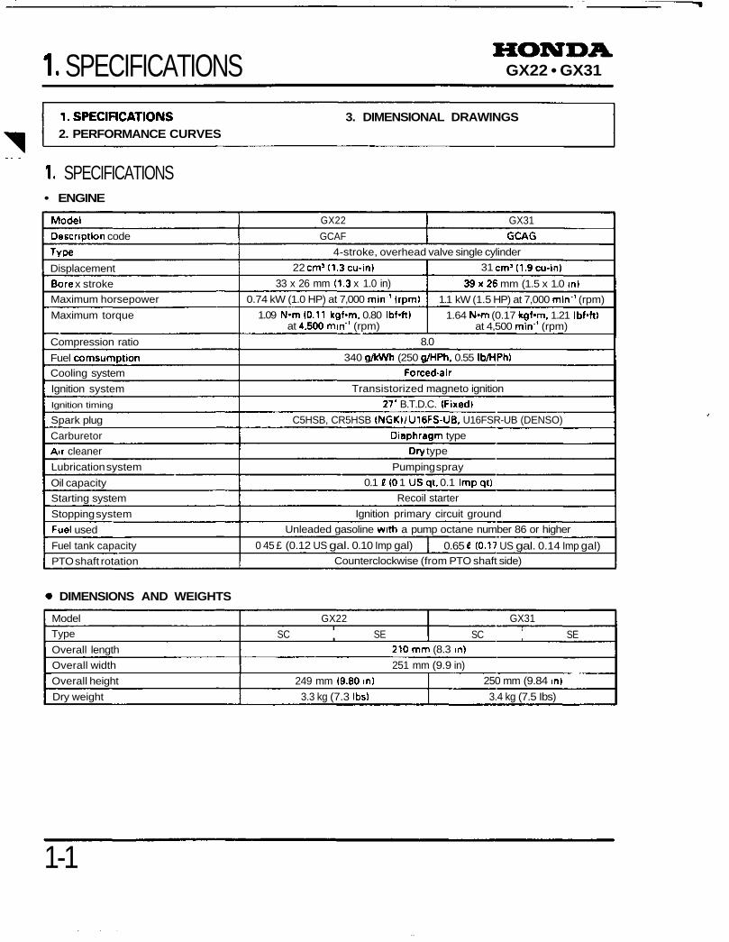
31 cmM1.9cu-in)
39x26 mm (1.5 x 1.0 in)
1.1 kW (1.5 HP) at 7,000 min'1 (rpm)
1.64 N-m (0.17 kgf-m, 1.21 Ibf'ft)at 4,500 min*1 (rpm)
8.0
340 g/kWh (250 g/HPh. 0.55 Ib/HPh)
Forced -air
Transistorized magneto ignition
27* B.T.D.C. (Fixed)
C5HSB, CR5HSB (NGKI/U16FS-UB, U16FSR-UB (DENSO)
Diaphragm type
Dry type
Pumping spray
0.1 t(Q 1 USqt, 0.1 Impqt)
Recoil starter
Ignition primary circuit ground
Unleaded gasoline with a pump octane number 86 or higher
0 45 £ (0.12 US gal. 0.10 Imp gal) 0.65 £ (0.17 US gal. 0.14 Imp gal)Counterclockwise (from PTO shaft side)
DIMENSIONS AND WEIGHTS
Model
Type
Overall length
Overall width
Overall height
Dry weight
GX22
SC SE
GX31
SC SE210mm (8.3 in)
251 mm (9.9 in)
249 mm (9.80 in)
3.3 kg (7.3 Ibs)
250 mm (9.84 in)
3.4 kg (7.5 Ibs)
1-1
GX22 • GX31
2. PERFORMANCE CURVES
GX22: GX31:
(HP)
£ 1.5-
2Ul
o i.o-X
r«
05-
(kW)1.25-
1.00-
0.75-
0.50-
n 9K-
(N
[2] MAXIMUM TORQUE
^^
[4] MA
^^
^-*
(IMUM
- .-
w
3O
U
l O "
P
r1
r*
§ui
o
ui
Ji
[3]
TO
RQ
UE
3[1
] H
OR
SE
PO
WE
RP
-
5ui
o
ui
ii
i M
i
_y
(N-m) (Ibtft)
(kW)1.25-
•1.00-
0.75-
0.50-
n »t;-
[211
X
MAXIMU
/
IM TORQUE
[41 MA
s^\
^
(IMUM
-« -,
,1
20J1.5 -
1 0" f\ e ^^
4.000 5,000 6,000 M: 7,000 8,000
[5] ENGINE SPEED [min ' (rpm)]
161'': Rated speed
4,000 5,000 6,000 ": 7.000 8,000
[5] ENGINE SPEED [min ' (rpm)]
[6] M: Rated speed
2. COURBES DEPERFORMANCES
(1] PUISSANCE(2) COUPLE MAXIMUM13) COUPLE(4] MAXIMUM[5] REGIME MOTEL'R dr/mnj|6] *1: Vitesse nominal
2. LEISTUNGSDIAGRAMMEII] MOTORLEISTUNG[2] MAXIMALES DREHMOMENT[31 DREHMOMENT[4] MAXIMALWERT[5] MOTOROREHZAHL <U/min)[6] •!. NENNDREHZAHL
2. CURVAS DE RENDIMIENTO[1] CABALLOS DE POTENCIA[2] TORSlbN MAXIMA[3j TORSION[4] MAXIMO[5] VELOCIDAD DEL MOTOR (rpm)[6] *1: Vdockiad nominal
1-2
GX22 • GX31
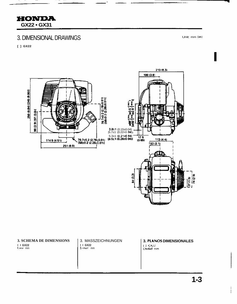
3. DIMENSIONAL DRAWINGS[ ] GX22
Unit: mm (m>
I210(8.3)
3.8±1 (0.15±0.04)|5.7±1 (0.22+0 04)]5.3±1 (0.211004)
3. SCHEMA DE DIMENSIONSI I GX22Unite mm
3. MASSZEICHNUNGENI I GX22Etnheit mm
3. PIANOS DIMENSIONALESGX_'J
nim
1-3
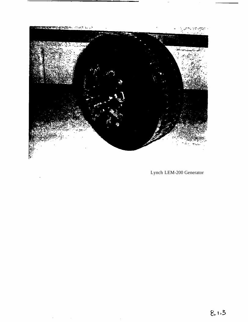
Lynch LEM-200 Generator
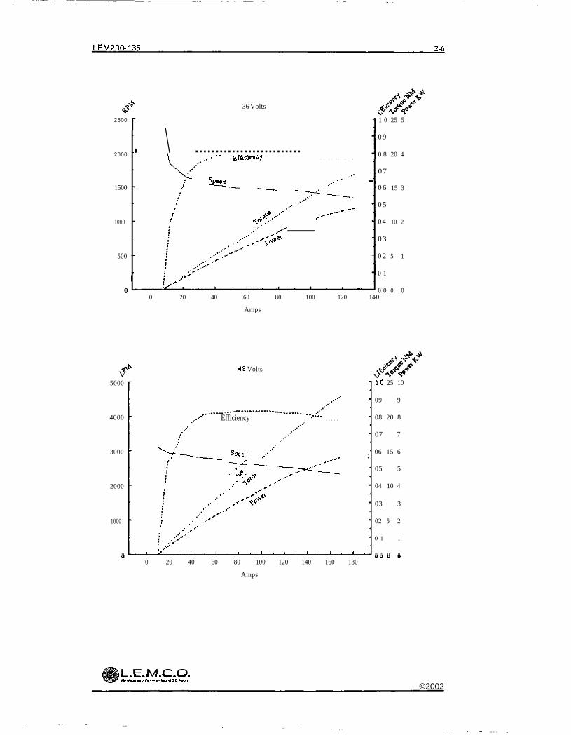
LEM200-135 2-6
36 Volts
2500
2000
1500
1000
500
•
. \\ ,..'"" Efficiency
r s^d___ — ^^^^^ -' «• ' '" ^-~
/ ^-""\ '""'...-•••^^s*
.••''*•••" '.x':'
0 20 40 60 80 100 120 14
Amps
1 0
0 9
0 8
07
0 6
0 5
0 4
0 3
0 2
0 1
0 00
25 5
20 4
15 3
10 2
5 1
0 0
4 8 VoltsV
5000
4000
3000
2000
1000
n
r
..-•''
Efficiency ..:<'k"s
"V^-__ SPeed ,.,"•"" ^ ;
~ x^ — ^^^^^l./ *^ .,"•'""'
/"' -^! ..-' ^-"'
' .•*' '/'<
I ••'•'i '/* i 1 , 1 , 1 . 1 . 1 , 1 . 1 . 1 .
10 25 10
09 9
08 20 8
07 7
06 15 6
05 5
04 10 4
03 3
02 5 2
0 1 1
n n n n
0 20 40 60 80 100 120 140 160 180
Amps
L E M C O^~ •*••• Ic^tf*^^*MinudouwiolPBTmnOTU^ntlDC Maori
©2002
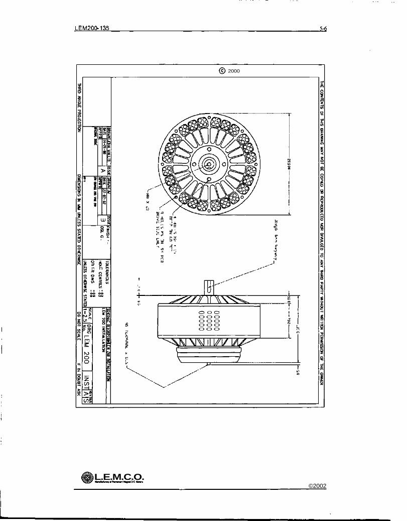
LEM200-135 5-6
2000
GD
n h
m
O O CDO O OO O OO O OO O O
L.E.M.C.O.©2002
10co
6o<N
LU
CNOoCVJ
©
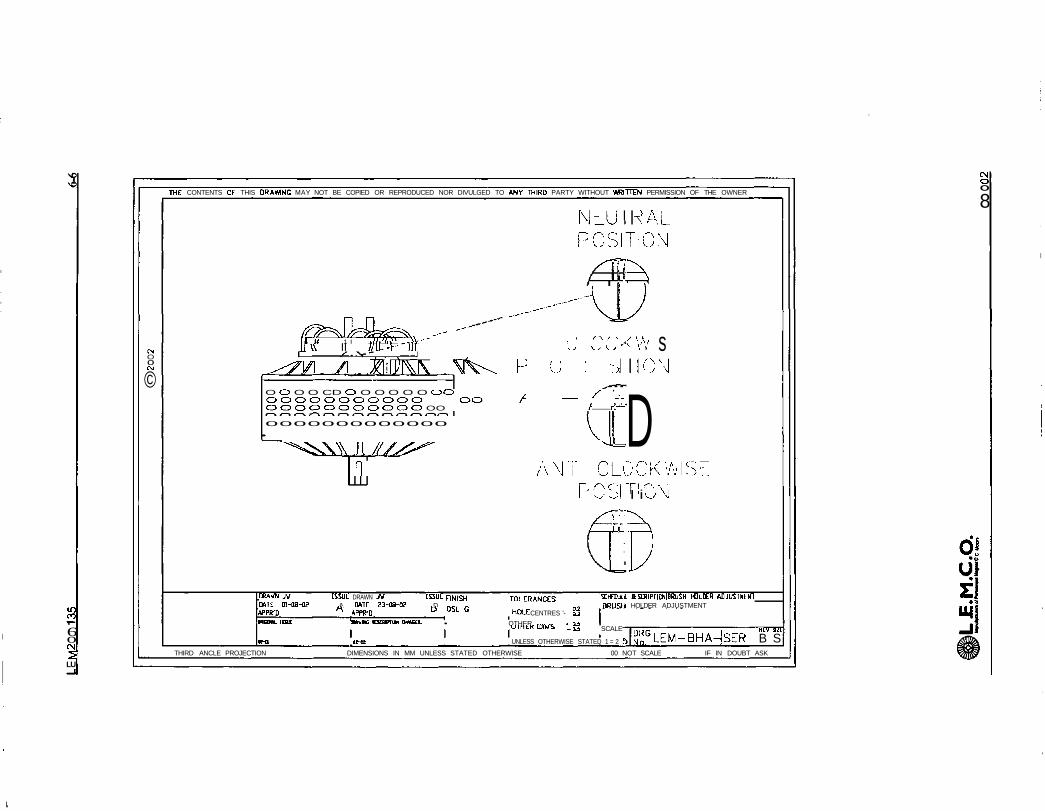
THE: CONTENTS OF THIS DRAWING MAY NOT BE COPIED OR REPRODUCED NOR DIVULGED TO ANV THIRD PARTY WITHOUT WRITTEN PERMISSION OF THE OWNER
NullPOSI
/"T*^
^--\ff^Jb^bz^ -' "'1 1 It 1 I ll '*^\ ^A~ "* ~~^ I ^ ' ' * ! /< ""If v\ II II[L- \\~ "ill '- j ^ } v ^ '
^<wi /I j?i!ij)i\\ MV^ h u : :,O C3 O O CD CD O O O O O OCD /^ 'ooooooooooo oo / — -'-OCDCDCDCDCDOOOC5O OO / rrj~"
0000000000000 \^
^^s\\\ \\///S>^ ^=
n /\ NT CL-:PC'o
XT7"/^-tp-
^ALTICM
^)
< vv s ~ON
DjCK 'ASETl "N\iI i w \
PDRAWN Jtf FSSUE DRAWN JV ISSUE piN|<^ Tm FRAMES SChCDULL ttSUilPriON|BRUSH HDLDEH ADJUSTMENTDATE 01-08-02 A DATE 23-09-0? D BRUSH HOLDER ADJUSTMENTAPPR-D A APPR-D D °JL G HOLE CENTRES '- gj
OWCWLIIM »**& DD.pn» <w*«. • OTHER DIMS * "umtK uiMi _u SCALE
OM iMt UNLESS OTHERWISE STATED 1 = 2 f
nrar RCV 31E
S^GLEM-BHA-SER B STHIRD ANCLE PROJECTION DIMENSIONS IN MM UNLESS STATED OTHERWISE 00 NOT SCALE IF IN DOUBT ASK
CNOO
8
d!
z»-
LU•
Lynch LEM-130 Motor
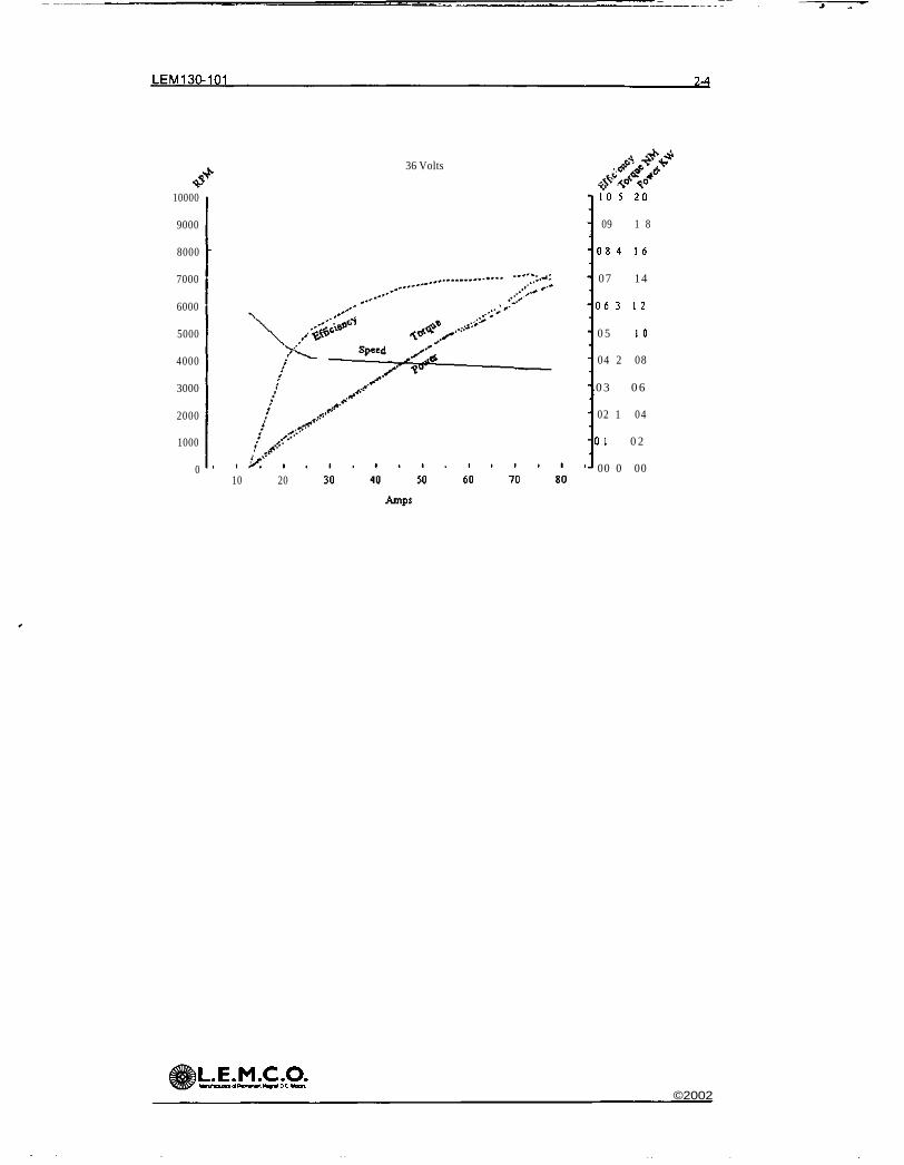
LEM130-101 2-4
36 Volts
10000
9000
8000
7000
6000
5000
4000
3000
2000
1000
0
1 0 5 2 0
09 1 8
0 8 4 1 6
07 14
0 6 3 1 2
0 5 1 0
04 2 08
0 3 0 6
02 1 04
0 1 0 2
00 0 0010 20
)L.E.M.C.O.HanAounnolP«nmntthgMDC Mom
©2002
THE CONTENTS OF THIS DRAWING UAY NOT BE COPIED OR REPRODUCED NOR DIVULGED TO ANY THIRD PARTY WITHOUT WRITTEN PERMISSION OF THE OWNER.
CMOO
6co
UJ
ypr^-^l f. Mflf i lT <,l-Af T-i^F T I '?-' ~IR I? 1MM F'Ac-'Vr," 3/lfc' CR -nMH wlDL7
r, i ni rs -ir x ••>PT
LE-I'
ru
695 —•** ~ G J J i
6:.s
55.0
000000000000
I
T
ISSUE DRAWN JV ISSUE
B
FINISH
OSL G
III OttMZ IX VM HO. Kl£L mimrw CHMKI M.SQ
HD1E MCU MDU1 S*ff KIAU.
TOLERANCES
HOLE CENTRES-SI
OTHER DIMS !g?
UNLESS OrHERWSE STATED
INSTflLLATIDNL£M 130 INSTALLATION
SCALE , cul= 2 No LEM1 IN5T B S
0!• o
Uiri
THIRD ANCLE PROJECTION DIMENSIONS IN MM UNLESS STATED OTHERWISE DO NOT SCALE IF IN DOUBT ASK

MOSFET ELECTRONICS P E
C O N T R O L L E :
MODELS 12O4/I205
CURTIS 4
D E S C R I R T I O
Curtis PMC Models 1204/1205
are power MOSFET electronic
motor speed controllers
designed to provide smooth,
silent, efficient and cost
effect ire speed, torque and
braking control.
W A R R A N T Y
One year from date of delivery.
ApplicationCurtis PMC MOSFET motor speed controllers are idealfor a variety of electric vehicle applications, includingindustrial trucks, personnel carriers, material handlingvehicles and golf cars, etc
Features:• High frequency switching and ultra low voltage
drops provide very high efficiency and silentoperation. Costs, heatsinkmg requirements andmotor and battery losses are reduced Low endtorque, range and battery life are increased
• Environmental protection provided by a ruggedanodized aluminum extrusion housing Simplemounting and wiring with push-on type connectorsfor control signals Plated solid copper busses usedfor all power connections
• Thermal protection and compensation circuit providesconstant current limit over operating range and undertemperature and over temperature cutback Nosudden loss of power under any thermal conditions.
• No adjustments are required
• Simple installation — Uses a two wire throttlepotentiometer.
• Potentiometer fault protection circuitry disablescontroller if throttle wires become open.
• High pedal disable prevents controller operation ifkey is turned on while throttle is applied.
• Plug braking or free wheeling options.
Specifications:• Frequency of Operation. 15 kHz
• Standby Current less than 20 mA
• Standard Throttle Input 0-5k ohms ±10%(others available)
• Weight 1204 1 8kg (4 Ibs),1205 2.7kg(6lbs)
• Full Power Operating Temperature Range-25°C to 75°C (controller temperature)
CURTIS INSTRUMENTS, INC. • 200 KISCO AVENUE • MT. KISCO, NY 10549 • TEL (914) 666-2971 • FAX (914) 666-2188CURTIS PMC • 6591 SIERRA LANE • DUBLIN, CA 94568 • (510) 828-5001 • FAX (510) 833-8777
CURTIS INSTRUMENTS, (UK) LTD. • 51 GRAFTON STREET • NORTHAMPTON NN1 2NT, ENGLAND • TEL (1604) 29755 • FAX (1604) 29876
CTRTISPMCMODIILS
1204-Oxx1204-lxx1204-2xx1204-3xx
12044xx1204-5xx
12(M-6xx1204-7xx
1205-lxx1205-2xx1205-3xx
VOITAGK(volts)
24-3624-3624-3624-36
36483648
1212
24-363648
12
CIRRI' NT(amps)
275175275175
275175
275175
400350400
2Mr\RUING(amps)
275175275175
275175
275175
400350400
5 MEN1
RYITNG(amps)
200130200130
200130
200130
275250275
1 HOI RRVITNG(amps)
12575
12575
12575
12575
175150175
VOLTAGEDROP
@100A
.35
.50
.35
.50
.35
.50
.35
.50
.25
.30
.25
IMJERVOITCl TRACK
(volts)
16161616
2121
99
16219
71(280")
33(013") *-B-»* . 133.3 .
(5.25")
DIM 1204 1205
A 174(685") 225(885")
B 19(075") 44(175")
84Dia
4 pics
22 (0 85") x 19 (075")x3.2(0125")Thk4 pics
16 J(065")~*
5")H-
Tr
L 113 J|* (4.45") *|
D i130.3(5 13")
146(5.75")
+
T1
71Dia(0.281")4 pics
Typical Wiring Diagram:
ControlWiringFuse
OptionalPrecfiarge Resistori—v'Vv—
Specifications subject to change without notice 50036 REV A 7/97
Modified Genesis Lithium-Ion Polymer Battery Pack
The Power of Dreams
Engines
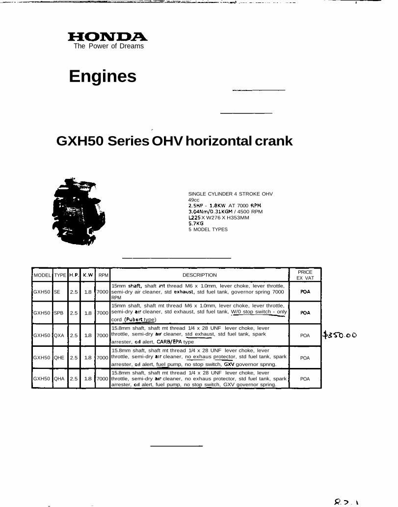
GXH50 Series OHV horizontal crank
SINGLE CYLINDER 4 STROKE OHV49cc2.5HP - 1.8KW AT 7000 RPM3.04Nm/0.31KGM / 4500 RPML225 X W276 X H353MM5.7KG5 MODEL TYPES
MODEL
GXH50
GXH50
GXH50
GXH50
GXH50
TYPE
SE
SPB
QXA
QHE
QHA
H.P.
2.5
2.5
2.5
2.5
2.5
K.W
1.8
1.8
1.8
1.8
1.8
RPM
7000
7000
7000
7000
7000
DESCRIPTION
15mm shaft, shaft mt thread M6 x 1.0mm, lever choke, lever throttle,semi-dry air cleaner, std exhaust, std fuel tank, governor spring 7000RPM
15mm shaft, shaft mt thread M6 x 1.0mm, lever choke, lever throttle,semi-dry air cleaner, std exhaust, std fuel tank, W/0 stop switch - only
cord (Pubert type)
15.8mm shaft, shaft mt thread 1/4 x 28 UNF lever choke, leverthrottle, semi-dry air cleaner, std exhaust, std fuel tank, spark
arrester, oil alert, CARB/EPA type
15.8mm shaft, shaft mt thread 1/4 x 28 UNF lever choke, leverthrottle, semi-dry air cleaner, no exhaus protector, std fuel tank, spark
arrester, oil alert, fuel pump, no stop switch, GXV governor spnng.
15.8mm shaft, shaft mt thread 1/4 x 28 UNF lever choke, leverthrottle, semi-dry air cleaner, no exhaus protector, std fuel tank, sparkarrester, oil alert, fuel pump, no stop switch, GXV governor spring.
PRICEEX VAT
POA
POA
POA
POA
POA
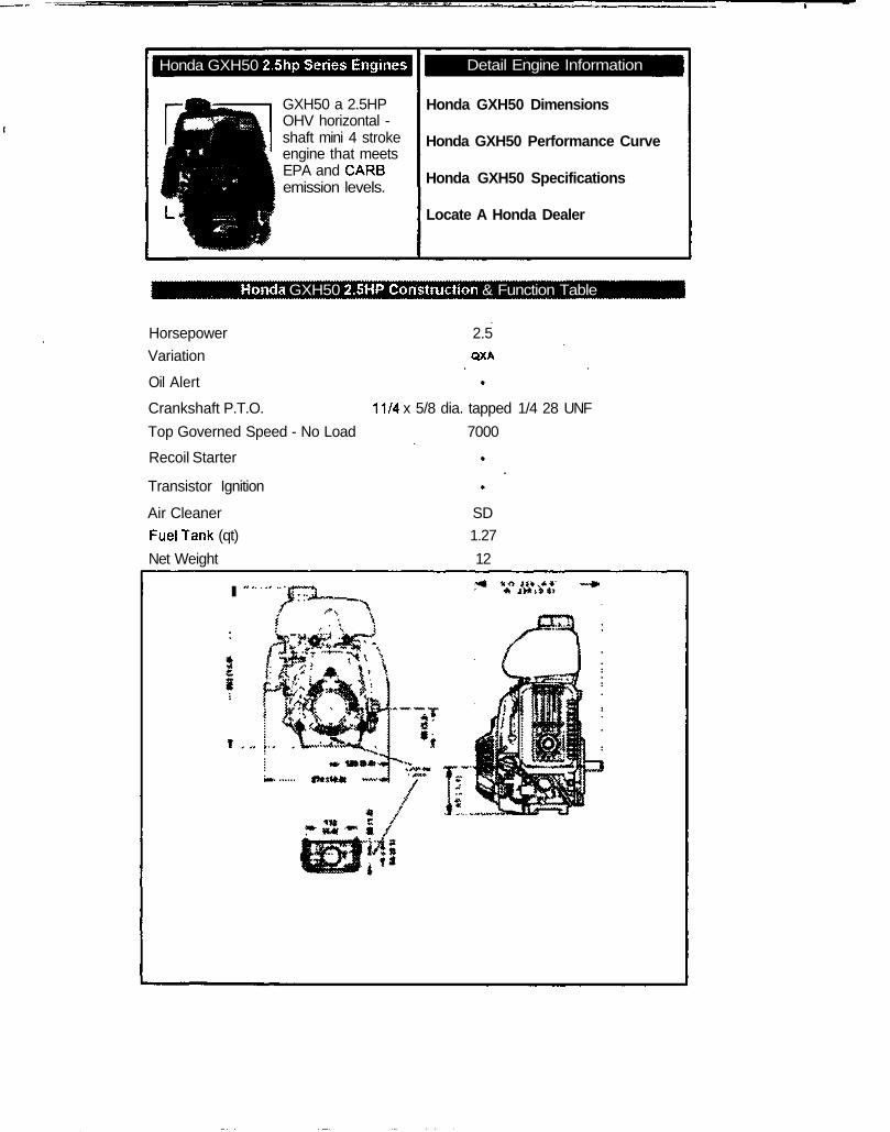
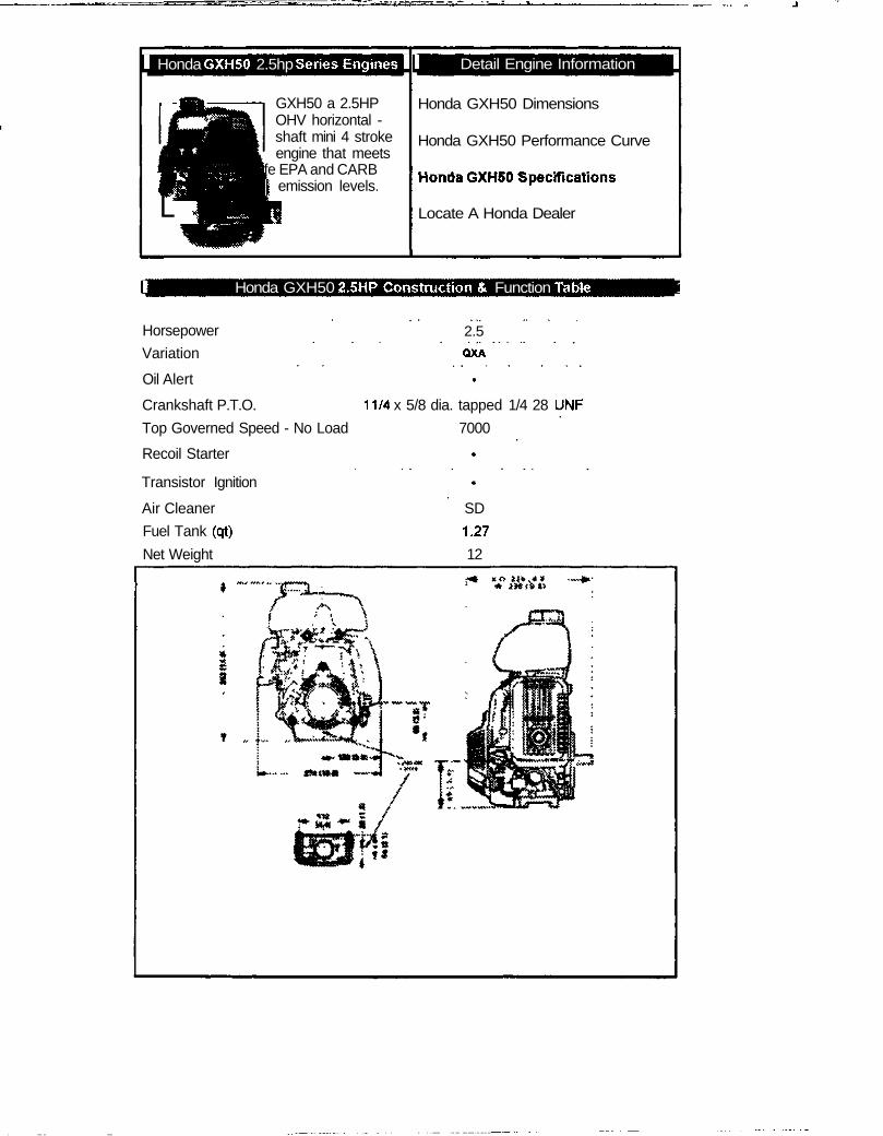
Honda GXH50 2.5hp Series Engines
GXH50 a 2.5HPOHV horizontal -shaft mini 4 strokeengine that meetsEPA and CARSemission levels.
Detail Engine Information
Honda GXH50 Dimensions
Honda GXH50 Performance Curve
Honda GXH50 Specifications
Locate A Honda Dealer
Honda GXH50 2.5HP Construction & Function Table
Horsepower 2.5
Variation QXA
Oil Alert
Crankshaft P.T.O. 11/4 x 5/8 dia. tapped 1/4 28 UNF
Top Governed Speed - No Load 7000
Recoil Starter
Transistor Ignition
Air Cleaner SD
Fuel Tank (qt) 1.27
Net Weight 12
I
1 Honda GXH50 2.5hp Series Engines 1
1 JHuHHu Bk.
liflWHL j iH^n
^^•^^^^ffw^
GXH50 a 2.5HPOHV horizontal -shaft mini 4 strokeengine that meets
fe EPA and CARB\ emission levels.
1 Detail Engine Information 1
Honda GXH50 Dimensions
Honda GXH50 Performance Curve
nonaa vvAnou opeciricaiions
Locate A Honda Dealer
1 Honda GXH50 2.5HP Construction & Function Table 1
Horsepower
Variation
2.5QXA
Oil Alert
Crankshaft P.T.O. 11/4 x 5/8 dia. tapped 1/4 28 UNF
Top Governed Speed - No Load 7000
Recoil Starter
Transistor Ignition
Air Cleaner SD
Fuel Tank (qt) 1.27
Net Weight 12
^jf' »lnrt»«*
eCycle - Motor/Generator Page 2 of 3
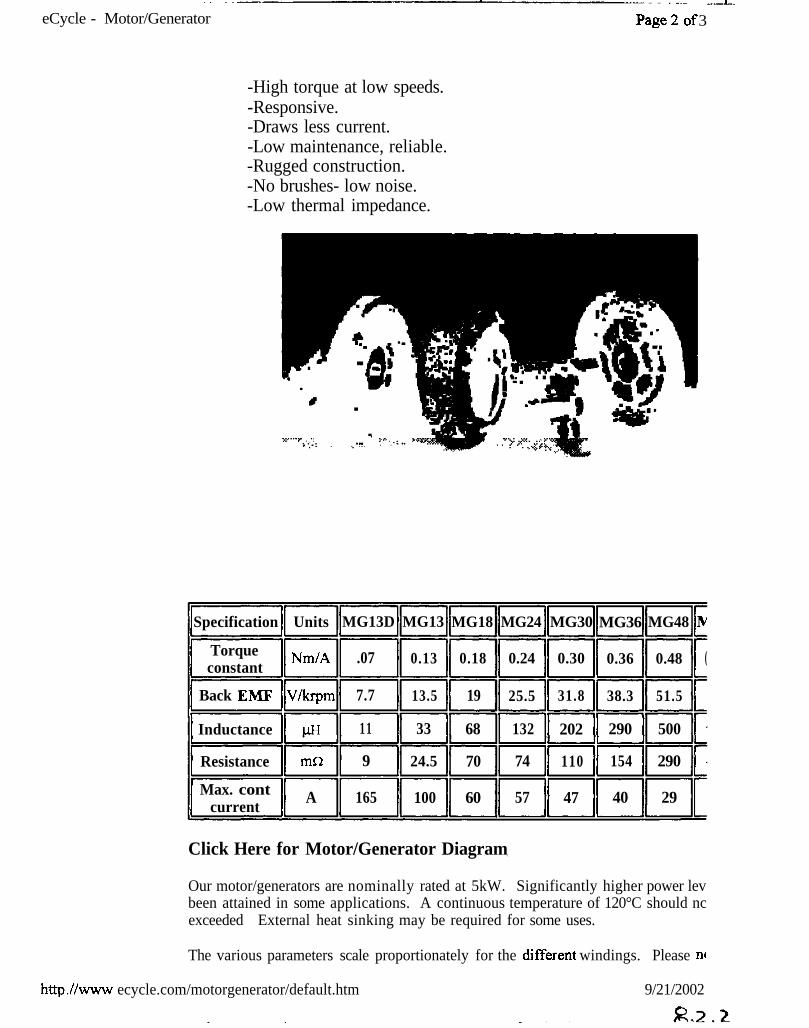
-High torque at low speeds.-Responsive.-Draws less current.-Low maintenance, reliable.-Rugged construction.-No brushes- low noise.-Low thermal impedance.
Specification
Torqueconstant
Back EMF
Inductance
Resistance
Max. contcurrent
Units
Nm/A
V/krpm
UH
mn
A
MG13D
.07
7.7
11
9
165
MG13
0.13
13.5
33
24.5
100
MG18
0.18
19
68
70
60
MG24
0.24
25.5
132
74
57
MG30
0.30
31.8
202
110
47
MG36
0.36
38.3
290
154
40
MG48
0.48
51.5
500
290
29
IV
(
Click Here for Motor/Generator Diagram
Our motor/generators are nominally rated at 5kW. Significantly higher power levbeen attained in some applications. A continuous temperature of 120°C should ncexceeded External heat sinking may be required for some uses.
The various parameters scale proportionately for the different windings. Please n«
http./Avww ecycle.com/motorgenerator/default.htm 9/21/2002
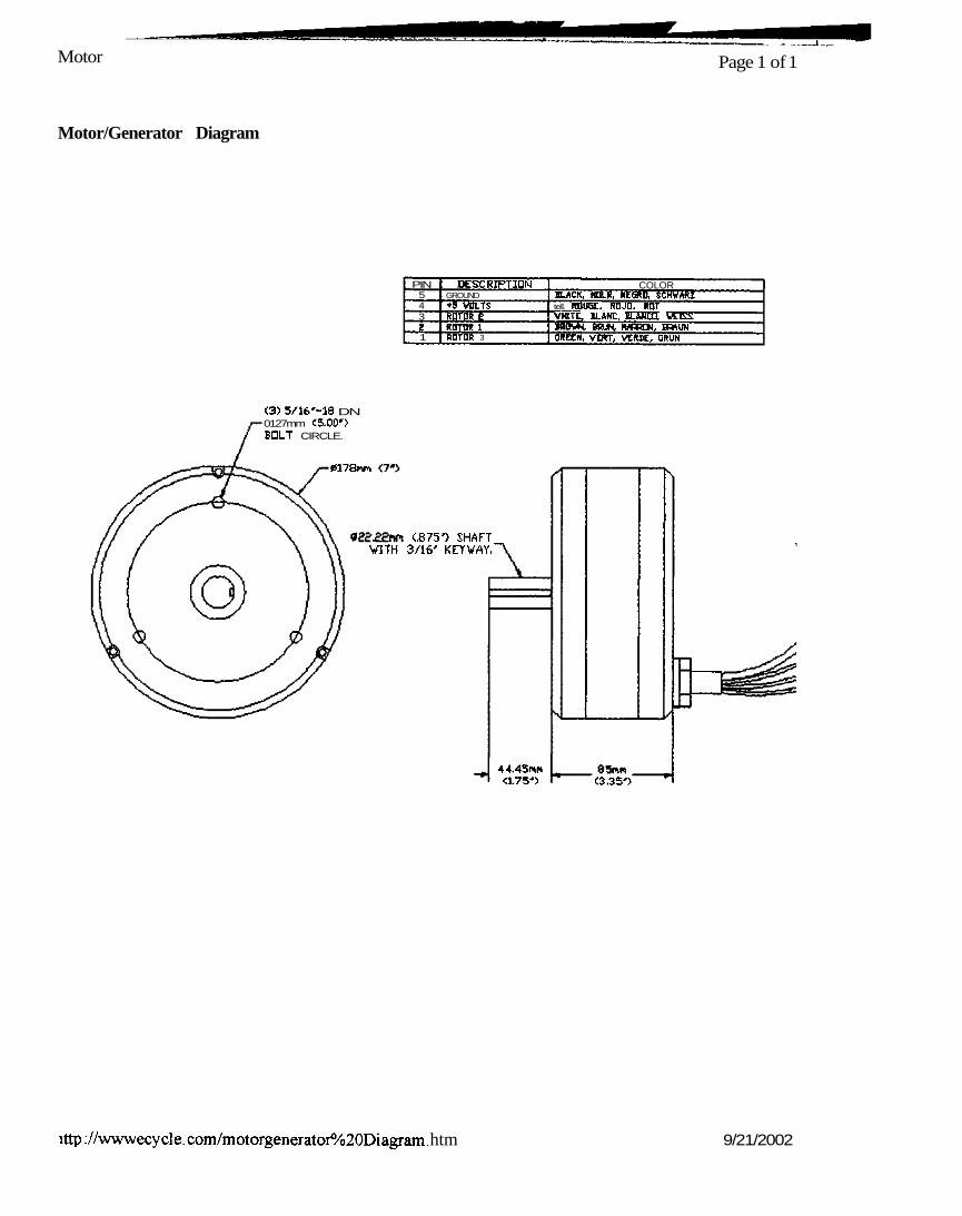
Motor Page 1 of 1
Motor/Generator Diagram
PIN543?1
DESCRIPTIONGROUND*5 VDLTSROTOR 8ROTOR IROTOR 3
COLORBLACK, NOLR, NEGRO, SCHWARZtell. RDU6C- RDJD. ROTVHITL, ILANC. ZLMlLU IA1&!JBOVH BfiUH WRRCM, BWUMORECN, VDRT, VERDE, GRUN
<3) 5/16'-18 DN0127mm C5,00'>BOLT CIRCLE.
0178™
(.875') SHAFTVITH 3/16' KEYVAY,"
44.45nn<1.75*> <3,35')
ittp ://www ecy cl e. com/m otorgenerator%20Di agram. htm 9/21/2002
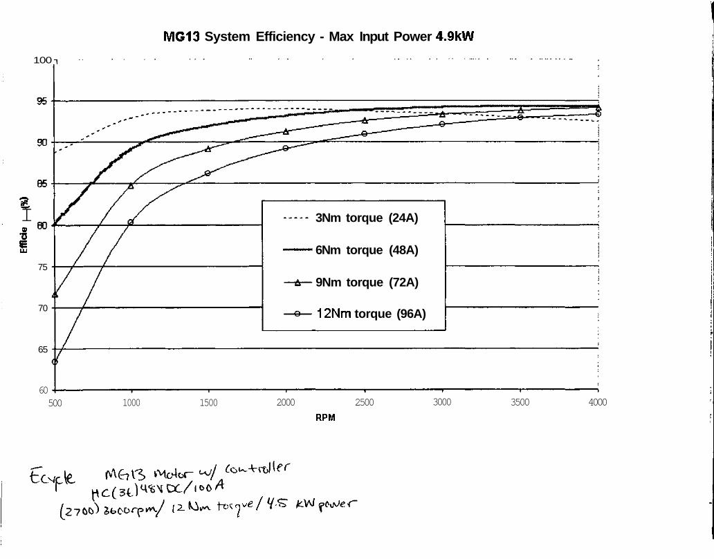
MG13 System Efficiency - Max Input Power 4.9KW
100 i
£IQ>
UJ
75
70
65
3Nm torque (24A)
6Nm torque (48A)
9Nm torque (72A)
12Nm torque (96A)
60500 1000 1500 2000 2500
RPM
3000 3500 4000
w'
(2- tc'7 /
IIIRIRIRIH mmIRIIIRIHIHIH RIRIRIRI
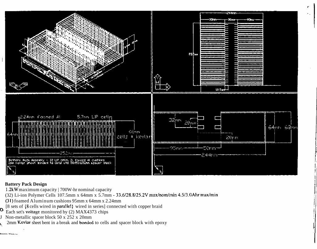
Battery Pack Design1.2kW maximum capacity | 700W-hr nominal capacity(32) Li-ion Polymer Cells 107.5mm x 64mm x 5.7mm - 33.6/28.8/25.2V max/nom/min 4.5/3.0Ahr max/min(31) foamed Aluminum cushions 95mm x 64mm x 2.24mm[8 sets of {8 cells wired in parallel} wired in series] connected with copper braidEach set's voltage monitored by (2) MAX4373 chips
J Non-metallic spacer block 50 x 252 x 20mmy 2mm Kev\ar sheet bent in a break and bonded to cells and spacer block with epoxy
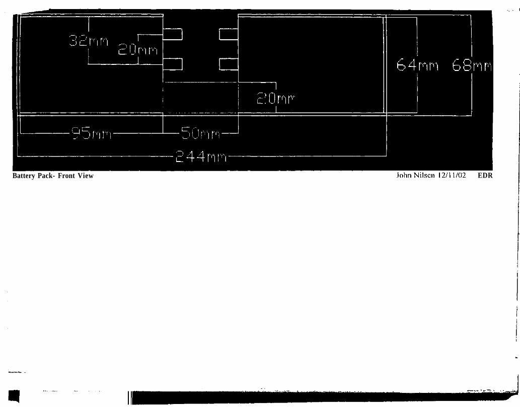
64mm 68nr
!0nr
£44mBattery Pack- Front View JohnNilscn 12/11/02 EDR
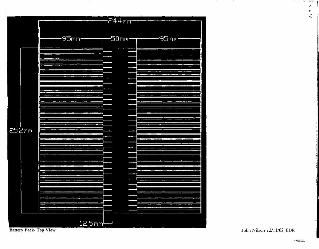
Battery Pack- Top View JohnNilscn 12/11/02 EDR
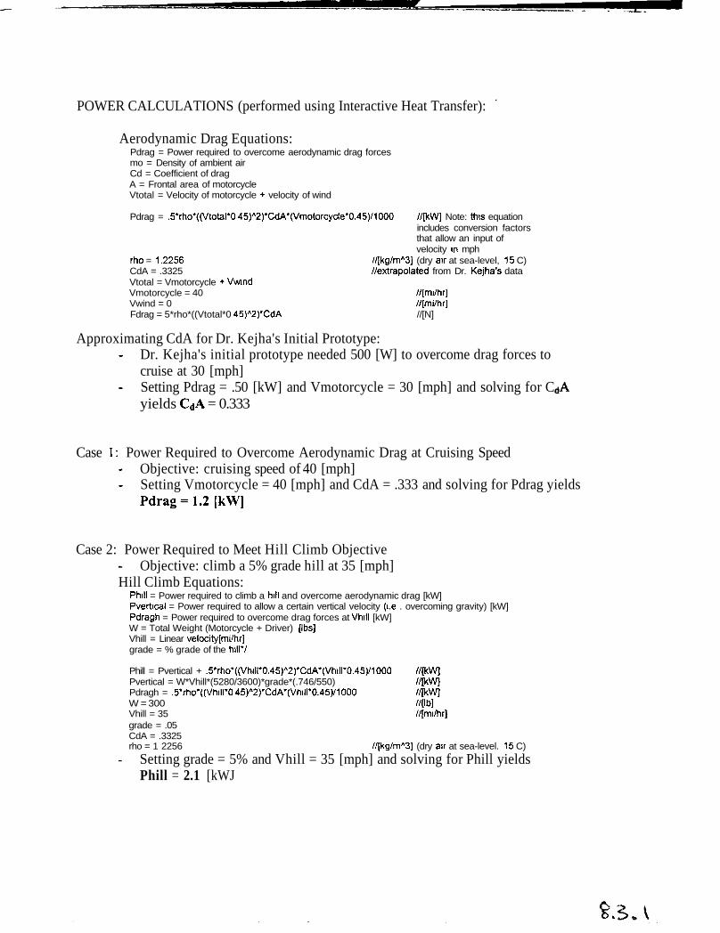
POWER CALCULATIONS (performed using Interactive Heat Transfer):
Aerodynamic Drag Equations:Pdrag = Power required to overcome aerodynamic drag forcesmo = Density of ambient airCd = Coefficient of dragA = Frontal area of motorcycleVtotal = Velocity of motorcycle + velocity of wind
Pdrag = .5*rho*((Vtotal*0 45)A2)*CdA*(Vmotorcycle*0.45)/1000 //[kW] Note: this equationincludes conversion factorsthat allow an input ofvelocity in mph
rho = 1.2256 //[kg/mA3] (dry air at sea-level, 15 C)CdA = .3325 //extrapolated from Dr. Kejha's dataVtotal = Vmotorcycle + VwmdVmotorcycle = 40 //[mi/hr]Vwind = 0 //[mi/hr]Fdrag = 5*rho*((Vtotal*0 45)A2)*CdA //[N]
Approximating CdA for Dr. Kejha's Initial Prototype:Dr. Kejha's initial prototype needed 500 [W] to overcome drag forces tocruise at 30 [mph]Setting Pdrag = .50 [kW] and Vmotorcycle = 30 [mph] and solving for Cyields CdA = 0.333
Case 1: Power Required to Overcome Aerodynamic Drag at Cruising SpeedObjective: cruising speed of 40 [mph]Setting Vmotorcycle = 40 [mph] and CdA = .333 and solving for Pdrag yieldsPdrag=1.2[kW]
Case 2: Power Required to Meet Hill Climb ObjectiveObjective: climb a 5% grade hill at 35 [mph]
Hill Climb Equations:Phill = Power required to climb a hill and overcome aerodynamic drag [kW]Pvertical = Power required to allow a certain vertical velocity (i.e . overcoming gravity) [kW]Pdragh = Power required to overcome drag forces at Vhill [kW]W = Total Weight (Motorcycle + Driver) [Ibs]Vhill = Linear velocity[mi/hr]grade = % grade of the hill*/
Phill = Pvertical + .5*rho*((Vhill*0.45)A2)*CdA*(Vhill*0.45)/1000 //[kW]Pvertical = W*Vhill*(5280/3600)*grade*(.746/550) //[kW]Pdragh = .5*rho*((Vhill*0 45)A2)*CdA*(Vhill*0.45)/1000 //[kW]W = 300 //[Ib]Vhill = 35 //[mi/hr]grade = .05CdA = .3325rho = 1 2256 //[kg/mA3] (dry air at sea-level. 15 C)
Setting grade = 5% and Vhill = 35 [mph] and solving for Phill yieldsPhill = 2.1 [kWJ
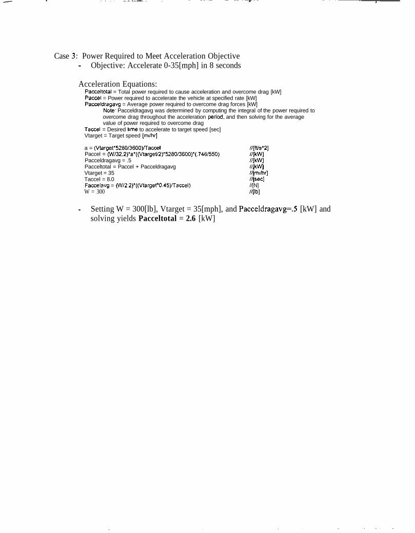
Case 3: Power Required to Meet Acceleration ObjectiveObjective: Accelerate 0-35[mph] in 8 seconds
Acceleration Equations:Pacceltotal = Total power required to cause acceleration and overcome drag [kW]Paccel = Power required to accelerate the vehicle at specified rate [kW]Pacceldragavg = Average power required to overcome drag forces [kW]
Note- Pacceldragavg was determined by computing the integral of the power required toovercome drag throughout the acceleration period, and then solving for the averagevalue of power required to overcome drag
Taccel = Desired time to accelerate to target speed [sec]Vtarget = Target speed [mi/hr]
a = (Vtarget*5280/3600)/TaccelPaccel = (W732.2)*a*((Vtarget/2r5280/3600)*(.746/550)Pacceldragavg = .5Pacceltotal = Paccel + PacceldragavgVtarget = 35Taccel = 8.0Faccelavg = (W/2 2)*((Vtarget*0.45)/Taccel)W = 300
//[ft/sA2]//[kW]//[kW]//[kW]//[mi/hr]//[sec]//[N]//[Ib]
Setting W = 300[lb], Vtarget = 35[mph], and Pacceldragavg=.5 [kW] andsolving yields Pacceltotal = 2.6 [kW]
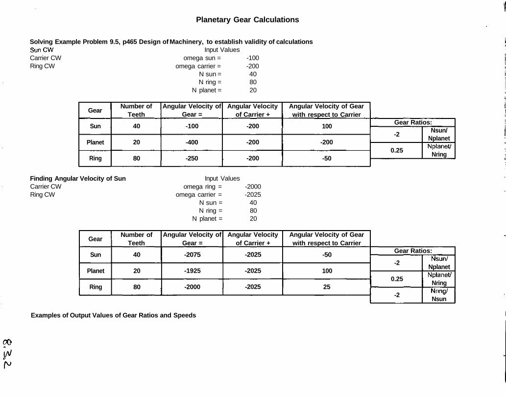
Planetary Gear Calculations
Solving Example Problem 9.5, p465 Design of Machinery, to establish validity of calculationsSunCWCarrier CWRing CW
Input Valuesomega sun = -100
omega carrier = -200N sun = 40N ring = 80
N planet = 20
Gear
Sun
Planet
Ring
Number ofTeeth
40
20
80
Angular Velocity ofGear =
-100
-400
-250
Angular Velocityof Carrier +
-200
-200
-200
Angular Velocity of Gearwith respect to Carrier
100
-200
-50
Gear Ratios:
-2
0.25
Nsun/NplanetNplanet/
Nring
Finding Angular Velocity of SunCarrier CWRing CW
Input Valuesomega ring = -2000
omega carrier = -2025N sun = 40N ring = 80
N planet = 20
Gear
Sun
Planet
Ring
Number ofTeeth
40
20
80
Angular Velocity ofGear =
-2075
-1925
-2000
Angular Velocityof Carrier +
-2025
-2025
-2025
Angular Velocity of Gearwith respect to Carrier
-50
100
25
Gear Ratios:
-2
0.25
-2
Nsun/NplanetNplanet/
NringNring/Nsun
Examples of Output Values of Gear Ratios and Speeds
Planetary Gear Calculations
Input Valuesomega ring =
omega carrier =N sun =N ring =
N planet =
-1750 omega sun= 2333.30 omega planet = -14000608010
Input Valuesomega ring =
omega carrier =N sun =N ring =
N planet =
-1750 omega sun= -3966.7-2700 omega planet = 4900
608010
Input Valuesomega ring = -1500
omega carrier = 0N sun = 40N ring = 80
N planet = 20
Input Valuesomega ring = -1500
omega carrier = -2700N sun = 40N ring = 80
N planet = 20
Input Valuesomega ring = -1500
omega carrier = -2000N sun = 40N ring = 80
N planet = 20
Input Valuesomega ring = -1500
omega carrier = -1000N sun = 40N ring = 80
N planet = 20
omega sun= 3000omega planet = -6000
omega sun= -5100omega planet = 2100
omega sun= -3000omega planet = 0
omega sun= 0omega planet = -3000
FT'
r^\ <~^~•} £-
Y'
ef' f'^<:•.. r: «•
- * > '
,l» » '
\ >
\/ j
5
it
^ ?•
r
-
-X,
r-V*
V
(,
V,
,• „ -rr*1
< < O
:'OA
&
'
.1
•^r«vuvM b- 'n«y
•b'8
o
o
o
j -SO I
I !*h^'0 j*— °1*VI
i I
\s~
'Vj
(T)
li.
ifli*Si
4 vS«>
V
*.«•
J,
2,0
.
'I- >.r
V
t
M
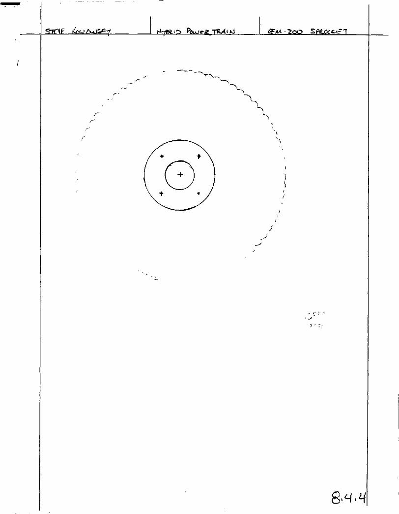
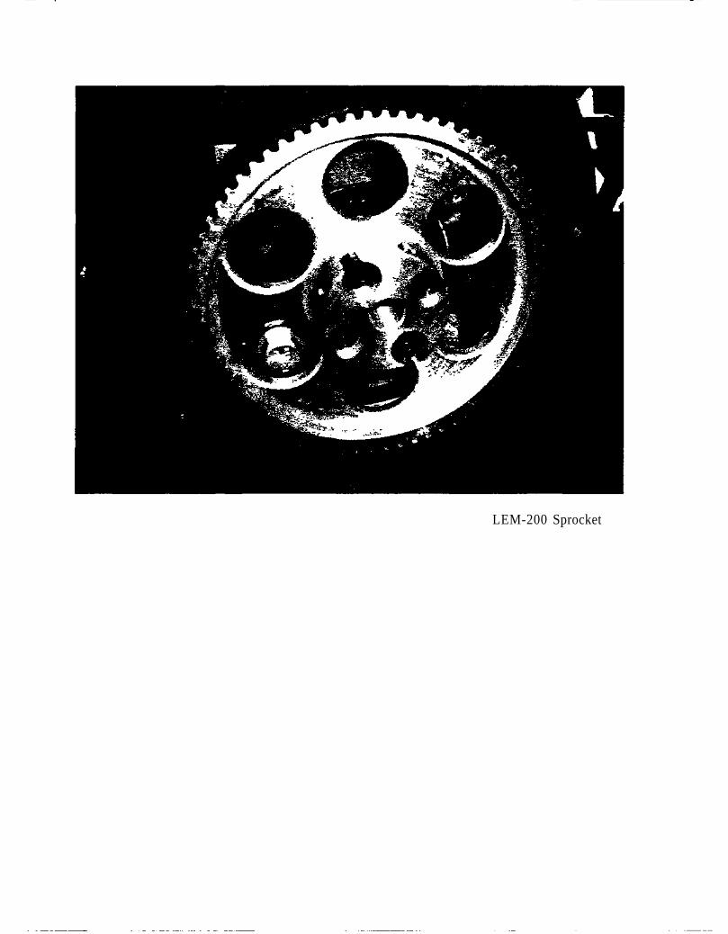
LEM-200 Sprocket
& . f>
os.
-£>•X
VJ
~6
Inft
:r00
0.3M
i-1/\
gs0T
U,
{^I ^
" «J
L _3
.
1
$ ^_
f
T
^^ —
™
KgyiJXy
^
^I
1 _- _j Ji !
1 ~ - ~ ~1
' '' 1^^ , l-fc / » 75",c ^/» 0 v ^ •- — - - — - -a
t
tor-o
L
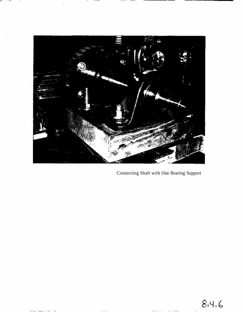
Connecting Shaft with One Bearing Support
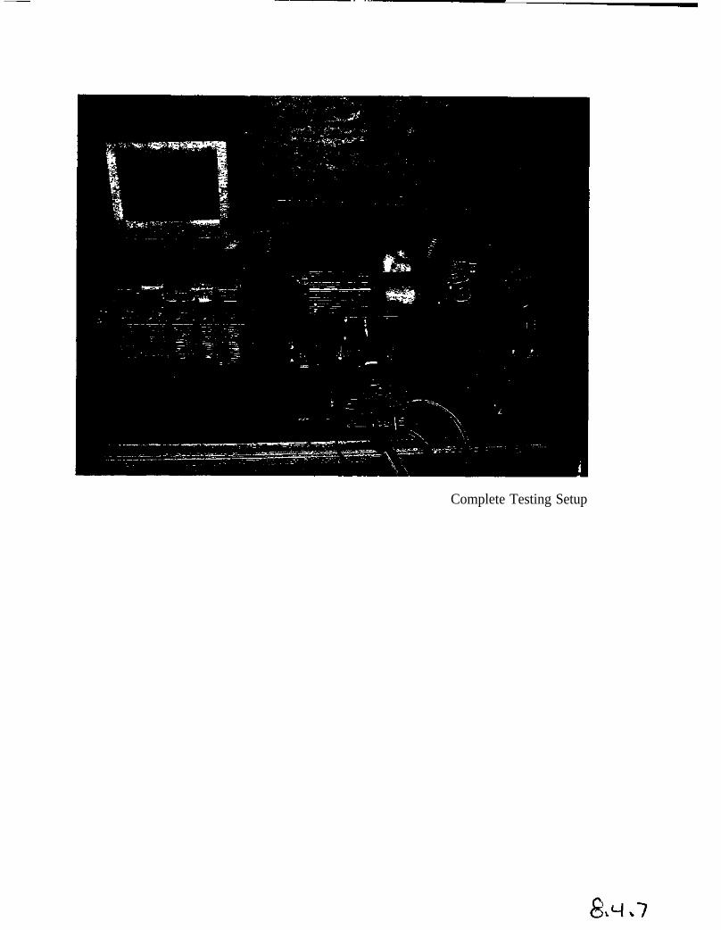
Complete Testing Setup

Dynamometer
40 60
70 V** " ***
? *0£
13.0
PSI
100
075 '?" 1.25050.
OJ5
036Ib/Hp-tr
1 74
2 DO
P«y>£PC | "-! -'
• ''-'r'3 lS iw'"'::''"V--.y-''. ':-' ^^auaG^^efrgjefat^s' ' '-'^-'^""^y^'^^jfe^ --^y-0 250 500 750 1000 1250 1500 1750 2000
H5T«3BBT54BET»5
Dynamometer Acquisition Software
Sl.8'0
(Tf
J,1
00
Hybrid-Electric Powertram ProtectGarrtt Chart
ID1
2
3
4
5
6
7
8
9
10
11
12
13
14
15
16
17
18
19
20
21
22
23
24
25
26
27
28
29
30
31
32
33
34
~35
36
37
36
39
~~40
41
42
Task NameResearch Senesvs Parallel
Actual Time Worked
Modeling Senesvs Parallel
Actual Time Worked
Selection of Motor / Controller
Actual Time Worked
Selection of Combustion Engine
Actual Time Worked
Selection of Generator
Actual Time Worked
Final Decision Senesvs Parallel
Actual Time Worked
Design of Battery Back
Actual Tune Worked
Acquisition of Motor / Controter
Actual Time Worked
Acquisition of Combustion Engine
Actual Time Worked
Acquisition of Generator
Actual Time Worked
Design of Chargmo/Throtttmg Circuits
Actual Time Worked
Design of Engine/Generator Interface
Actual Time Worked
Acquisition of Charging/Throttling Circuits
Actual Time Worked
Design of Testing Setup/Procedures
Actual Time Worked
Construction of Battery Pack
Actual Time Worked
Construction of Charging/Throttling Circuits
Actual Time Worked
Constructaon of Engine/Generator Interface
Actual Time Worked
Construction of Controlling Electronics
Actual Time Worked
Construction of Bench-Test Setup
Actual Time Worked
Initial Component Testing
Actual Tone Worked
Final System Testing
Actual Time Worked
Project Final Gantt Chart Protected WeDate Thu 5/8/03Andrew Stuckey
Sep'02 Oct'02 Nov'02 Dec '028/25 9/1 9/8 9/15 9/22 9/29 10/6 10/13 10/20 10/27 11/3 11/10 11/17 11/24 12/1 12/8 12/15 12/22
9/4 | | 1Q/31
9M [ , . /; ' •; . /, ^ . :, ,,...-. , • 1 11/22
10/14 | | 10/31
10/14 | .; , ..V ] 11/22
10/29 p r~~' | 11/6
10/31 . ' ; ,,] 11«2
10/29 | ' \ . | 11/6
10/29 | | 11/1
10/29 \ ..'• ( 1 | | 11/6
10/29 1 ;" ; ; , ' , . ; ,. ;i n/is10/31 Q 10/31
11/22 [] 11/22
11/6 | . :; . | 11/19
11/ie | ,:- ( ; . „ • , | ia«11/6 [, ' . , ;, ; ; ''] 11/19
11«2 | " /'. ; ;." , v; .':"i"V'; ; ' " .> ;. ••''''"'.•./
11/6 | | 11/19
11/22 [] 11/22
11/B | , . ,, : \ 11/19
11/22 [] 11/22
11/12 | j 11/26
"'« [ ;r":V ' ' ••• , ' ' , , . , • , • . . • • ' . ' . , :
H'1» [iV^'y" ) H««
11/4 j , . ', ; 1 12/2
11/19 |i '•..?;''!£.;• , •' ., „•„ :| 12«
"»i : , " " - . ' • • , . . • . - . : • , ; , . • , • : • •11/6 [ , / ] 11/26
11/6 | . ., \ • , C " , ] 11«2
irk Dates | •. ... ' ] Actual Work Dates | |
Pagel
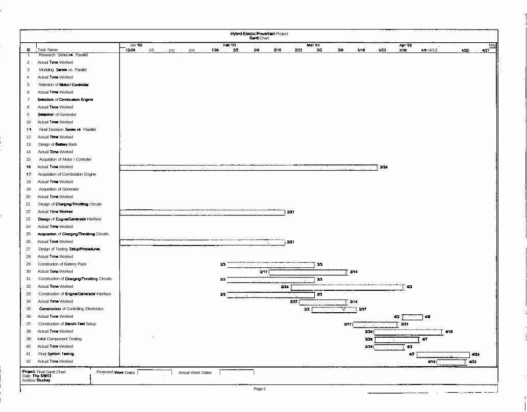
Hybrid-Electric Powertrain ProjectGantt Chart
10 Task Name1 Research Series vs Parallel
2 Actual Time Worked
3 Modeling Senas vs Parallel
4 Actual Time Worked
5 Selection of Motor /Controller
8 Actual Time Worked
7 Selection of Combustion Engine
8 Actual Time Worked
0 Selection of Generator
10 Actual Time Worked
1 1 Final Decision Series vs Parallel
12 Actual Time Worked
13 Design of Battery Back
14 Actual Time Worked
15 Acquisition of Motor / Controller
16 Actual Time Worked
1 7 Acquisition of Combustion Engine
18 Actual Time Worked
19 Acquisition of Generator
20 Actual Time Worked
21 Design of Charging/Throttling Circuits
22 Actual Time Worked
23 Design of Engine/Generator Interface
24 Actual Time Worked
25 Acquisition of Charging/Throttling Circuits
26 Actual Time Worked
27 Design of Testing Setup/Procedures
28 Actual Time Worked
29 Construction of Battery Pack
30 Actual Time Worked
31 Construction of Charging/Throttling Circuits
32 Actual Time Worked
33 Construction of Engine/Generator Interface
34 Actual Time Worked
35 Construction of Controlling Electronics
36 Actual Time Worked
37 Construction of Bench-Test Setup
38 Actual Time Worked
39 Initial Component Testing
40 Actual Time Worked
41 Final System Testing
42 Actual Time Worked
Project. Final Gantt Chart Protected WeDate Thu 5/8/03Andrew Stuckey
Jan t>3 Fab '03 Mar '03 Apr '03 , May12/29 1/5 1/12 1/19 1/26 2/2 2/9 2/16 2/23 3/2 3/9 3/16 3/23 3/30 4/6 \4/13 4/20 4/27
' ' ' ; ," ' / i | 3/24
| 2/21
I 2/21
2/3 ] an
2/17 | ] 3/14
2/3 . . , . | 3/3
2/24 [ | 4/2
*3 • : . , , , ' ' :„ ' 1M
2/27 | | 3/14
3/3 [ V | 3/17
4/2 | ]4/8
3/17 | , , | 3/31
3/24 [ | 4/16
3/24 | ; 1 <"
3/24 [ ] 412
4/7 [ , J4/24
4/14 | ] 4/23
irk Dates | | Actual Work Dates | |
Page 2