
Hybrid Drive Systems for Vehicles - IEA
75
© 2018 LTH - LU 1 Hybrid Drive Systems for Vehicles L9 - Charging EHS © Mats
Transcript of Hybrid Drive Systems for Vehicles - IEA
© 2018 LTH - LU 1
Hybrid Drive Systems for Vehicles
L9 - Charging
EHS
© Mats
© 2018 LTH - LU 2
Static Charging

© 2018 LTH - LU 3
On boardOff board
On board / Off board = AC / DC
• ”AC Charging”
• Automation missing
• High power plug missing?
• 10...100 MW/m2
• ” DC Charging”
• Automation missing
• 10...100 MW/m2
• ”Wireless Charging”
• 10...100 kW/m2

© 2018 LTH - LU 4
• Commercial Vehicles
– May be Opportunity Charged up to 10 ... 20 times a day
– The power level is high!– Automatic connection absolutely
necessary !!!
• Autonomous private (?) vehicles
– Maybe a Spotify/Netflix/Uber kind of vehicle
– Must be able to autonomously arrange washing, charging, workshop visit, ...
– Usually connected 1...3 times per day– Automatic connection absolutely
necessary !!!
Who needs an Automatic Charging Connection ... ?
© 2018 LTH - LU 5
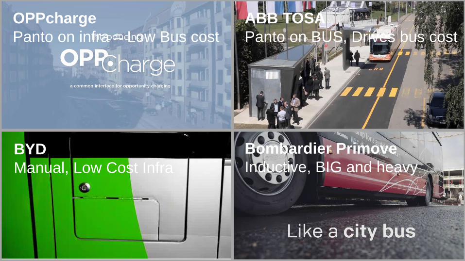
ABB TOSA
Panto on BUS, Drives bus cost
BYD
Manual, Low Cost Infra
OPPcharge
Panto on infra = Low Bus cost
Bombardier Primove
Inductive, BIG and heavy
© 2018 LTH - LU 6
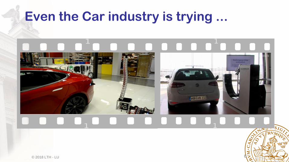
Even the Car industry is trying ...
© 2018 LTH - LU 7
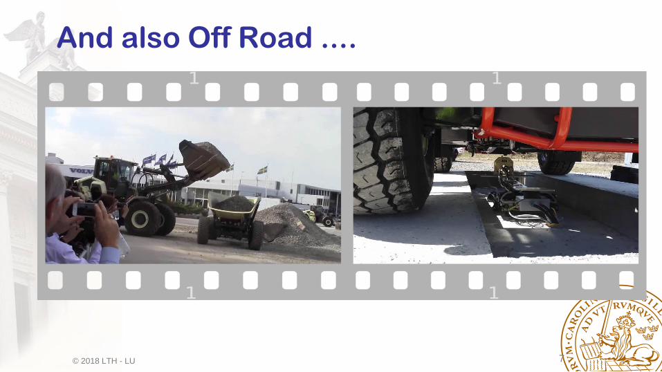
And also Off Road ....

© 2018 LTH - LU 8
The gardening industry is leading ...

© 2018 LTH - LU 9
But we are still pushing the limits ...
• Same CCS-plug, now called ”CCSplus”, boosted with water cooling.
• Current limits pushed towards 350 Ampére and beyond.
= 260 ... 500 kW, depending
• Still no automation!
© 2018 LTH - LU 10
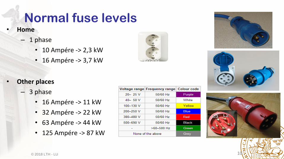
Normal fuse levels• Home
– 1 phase
• 10 Ampére -> 2,3 kW
• 16 Ampére -> 3,7 kW
• Other places
– 3 phase
• 16 Ampére -> 11 kW
• 32 Ampére -> 22 kW
• 63 Ampére -> 44 kW
• 125 Ampére -> 87 kW
IEC 60309
Color -> Voltage
Diameter -> Current

© 2018 LTH - LU 11
Charging Mind Map
Charging
Conductive
DC AC
Inductive

© 2018 LTH - LU 12
Dedicated Charging StationsIEC 62196
© 2018 LTH - LU 13
© 2018 LTH - LU 14

© 2018 LTH - LU 15

© 2018 LTH - LU 17
The Chademo Charging Station
”CHaDeMo” = ”CHarge DE Move”
in English
OR
”o CHA DEMO ikaga desuka”
in Japanese
= ”Let’s have tea while charging”

© 2018 LTH - LU 18
Chademosuppliers
44 kW
max 63 A AC
OR
50 kW
max 500 V, max 125 A DC
© 2018 LTH - LU 19
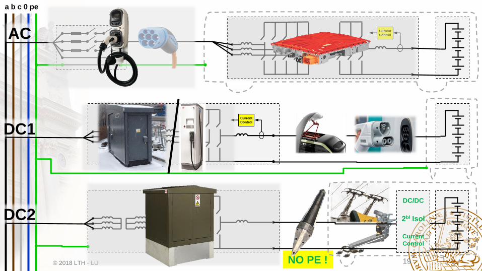
Current
Control
a b c 0 pe
Current
Control
NO PE !
AC
DC1
DC2DC/DC
2bl Isol
Current
Control

© 2018 LTH - LU 20
a b c 0 pe
Current
ControlAC
• 3 phase plug limited to 63 A
• Max charging power 44 kW
• Available from all OEMs for night time
charging
• E.g. 200 kWh in 5 hours night time.
• NOT Enough for Opportunity Charging at
+100 kW? There is a possibility!
• New Plug Needed for higher power levels!
DC&AC
63 -> 150 A/pin
= 104 kW AC

© 2018 LTH - LU 21
Current
Control
a b c 0 pe
AC
DC1
DC2
• OppCharge an open ”standard”, capable of up to 600 kW
• Expensive stations, not compatible with most truck applications
• CCS/DC normally limited to 200 A.
• @ 750 V this gives 150 kW, e.g 4x0.25h = 150 kWh
• NOT automatic
• Pushed towards 500 A with water cooling = 375 kW
@ 750 V

© 2018 LTH - LU 22
a b c 0 pe
NO PE !
DC2DC/DC
2bl Isol
Current
Control
• Siemens eHighway is currently leading
• Others follow very soon
• Significant battery size reduction (-60%...-80%)
• 150 kWh instead of 600 kWh
• No protective earth – requires special safety
solutions

© 2018 LTH - LU 23
Tesla Semi Analysis ...

© 2018 LTH - LU 24
• GVW = 80000 lbs = 36 287 kg
• Drag Coefficient = Cd = 0.36
• Drivetrain: 4 PM motors from Model 3
• Acceleration 0-60 mph = 0-97 km/h
– Tractor only: 5 seconds
– Full load (80000 lbs): 20 seconds
• Hill climbing: 5 % slope @ 65 mph = 105 km/h
• Range: 300/500 miles = 483/805 km
• Charging time: 400 miles = 644 km in 30 minutes
Technical factsGiven Facts Calculated Facts
• Energy consumption = about 1 kWh/km
• Tractor weight = 9 tons
• Traction motors = 4 x 137/192 kW (cont/peak)
• Battery Energy = 850 – 950 kWh (depends on DoD)
• Battery Weight = 4.2 – 4.7 tons (@ 0.2 kWh/kg)
• Charging power
= almost 1.3 Megawatt for Fast Charging
= 100 kW for Night Time Charging
• MEGA Charging Connector: Seems to be 4xSUPER
Charging Connector
X 4 =

© 2018 LTH - LU 25
Is automatic
Works with bothsmall and BIG vehicles
Can be used both when
standing still and when moving
Can be used both
in the city and on the highway
The Perfect Charging Connection ...

© 2018 LTH - LU 26
Dynamic Charging
© 2018 LTH - LU 27
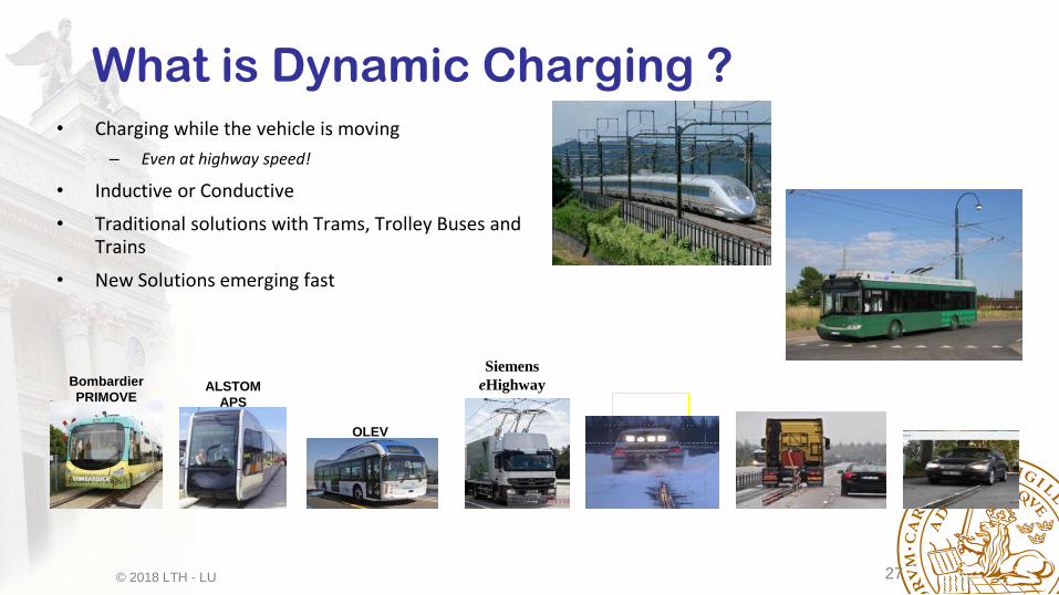
• Charging while the vehicle is moving
– Even at highway speed!
• Inductive or Conductive
• Traditional solutions with Trams, Trolley Buses and Trains
• New Solutions emerging fast
What is Dynamic Charging ?
ALSTOM
APS
OLEV
Bombardier
PRIMOVE
Siemens
eHighway
Elways AlstomElOnRoad

© 2018 LTH - LU 28
Conductive ERS concepts
HondaElways Alstom Elonroad Siemens

© 2018 LTH - LU 29
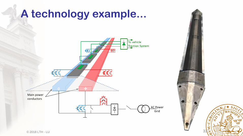
Additional equipment neededTank Engine
Transmission Wheel
Battery Electric Drive
Pick Up Electric
Power
Conditioner
Power
Supply
Transformer
Conventional vehicleHybrid VehiclePlug In Hybrid VehicleSlide In Hybrid Vehicle
© 2018 LTH - LU 30
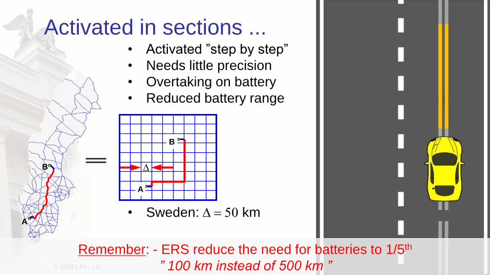
Activated in sections ...• Activated ”step by step”
• Needs little precision
• Overtaking on battery
• Reduced battery range
• Sweden: D = 50 km
D
A
B
A
B
Remember: - ERS reduce the need for batteries to 1/5th
” 100 km instead of 500 km ”

© 2018 LTH - LU 31
Elways
Alstom/Volvo
Elonroad
-80 % battery size !
Elonroad
Siemens

© 2018 LTH - LU 32
Vision of one technology supplier ...
© 2018 LTH - LU 33
A technology example...

© 2018 LTH - LU 34
© 2018 LTH - LU 35
Cost of Charging

© 2018 LTH - LU 36
Some cost analysis ...• 5 million cars á 15 kWh
batteries á 1000 SEK/kWh@ 10 years lifetime-> 7 Billion SEK/year
• 50 000 Heavy Duty Trucks á 100 kWh batteries á 1000 SEK/kWh @ 2 years lifetime
-> 2 Billion SEK/year
• 15 600 km National and European road á 10 Million SEK/km @ 20 years lifetime-> 8 Billion SEK/year -> 17 Billion
SEK /year
• 5 million cars á 75 kWh batteries á 1000 SEK/kWh@ 10 years lifetime-> 38 Billion SEK/year
• 50 000 Heavy Duty Trucks á 500 kWh batteries á 1000 SEK/kWh @ 2 years lifetime
-> 12 Billion SEK/year
• 50 000 ”SuperChargers” á 150 kW á 6000 SEK/kW @ 25 years lifetime-> 1 Billion SEK/year
500 ”MEGAChargers” á 1000 kW á 6000 SEK/kW @ 25 years lifetime-> 0,12 Billion SEK/year
-> 51 Billion
SEK /year
• Bränsle i transportsektorn: c:a 90 TWh = 9e9 liter = 45 Milliarder SEK exkl skatter !
• Motsvarande El = 30 TWh = 30 Milliarder SEK exkl skatter !
• Skillnad = 15 milliarder SEK !

© 2018 LTH - LU 37
Principles for galvanic isolation, double isolation and integration

© 2018 LTH - LU 38
Fundamental isolation issues (1)
BATTERY
AUX
AC
Gri
d
TVS
1. When connected for charging,
a part of the TVS will be on
the same electric potential
system as the utility grid.
2. Without galvanic isolation, the
entire charging and TVS
system will be on grid
potential
3. The TVS system has
impedances to chassie
(parasitic and intentional)
4. These impedances depend on the TVS size and
routing, and maybe on body builder installations
5. The charging system will drive currents (difficult to
predict) via these parasitic impedances to ground.
6. Additional components need to be installed in the TVS
to limit these parasitic currents, not to trigger Residual
Current Devices (RCD’s) in the grid connection.
7. We do not yet know the extent of the need for these
additional components. Studies are underway, but no
strong answers can be expected before the end of 2018.
Charging
System
© 2018 LTH - LU 39
Fundamental isolation issues (3)
BATTERY
AUX
AC
Gri
d
Charging
System
TVS
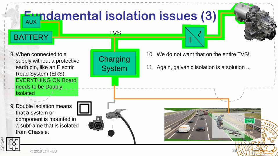
8. When connected to a
supply without a protective
earth pin, like an Electric
Road System (ERS),
EVERYTHING ON Board
needs to be Doubly
Isolated
9. Double isolation means
that a system or
component is mounted in
a subframe that is isolated
from Chassie.
10. We do not want that on the entire TVS!
11. Again, galvanic isolation is a solution ...
© 2018 LTH - LU 40
Fundamental isolation issues (4)
BATTERY
AUX
AC
Gri
d
Charging
System
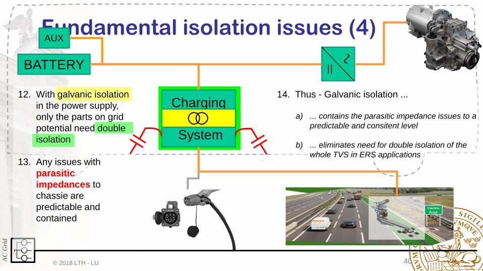
12. With galvanic isolation
in the power supply,
only the parts on grid
potential need double
isolation
13. Any issues with
parasitic
impedances to
chassie are
predictable and
contained
14. Thus - Galvanic isolation ...
a) ... contains the parasitic impedance issues to a
predictable and consitent level
b) ... eliminates need for double isolation of the
whole TVS in ERS applications
© 2018 LTH - LU 41
Applied to AC Charging

© 2018 LTH - LU 42
Solutions for galvanic isolation with AC Charging (1)
BATTERY
AUX
AC
Gri
d
PEC
84
110 kW
1. ON board chargers
are always
galvanically isolated.
2. We can use some of
them, like in this
example 5x22 kW =
110 kW
3. Weight: 100 kg
4. Size: 520x400x420
5. That is with one traction
machine

© 2018 LTH - LU 43
Solutions for galvanic isolation with AC Charging (2)
BATTERY
AUX
AC
Gri
d
84
110 kW
6. It can also be done
with two traction
machines
© 2018 LTH - LU 44
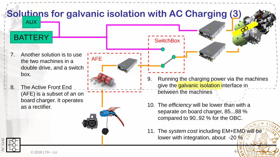
Solutions for galvanic isolation with AC Charging (3)
BATTERY
AUX
AC
Gri
d
AFE
SwitchBox
7. Another solution is to use
the two machines in a
double drive, and a switch
box.
8. The Active Front End
(AFE) is a subset of an on
board charger. It operates
as a rectifier.
9. Running the charging power via the machines
give the galvanic isolation interface in
between the machines
10. The efficiency will be lower than with a
separate on board charger, 85...88 %
compared to 90..92 % for the OBC.
11. The system cost including EM+EMD will be
lower with integration, about -20 %

© 2018 LTH - LU 45
System Cost AC Charging1 x 240/400 kW Cont/Peak + 110 kW OBC
OR
2 x 120/200 kW Cont/Peak
© 2018 LTH - LU 46
Including ERS Charging

© 2018 LTH - LU 47
Including AC and ERS charging compatibility (1)
BATTERY
AUX
AC
Gri
d
1. The OBC contains the
galvanically isolated
DC/DC that ERS
needs, and only
double isolation needs
to be added
2. The OBC consists of
an Active Front End
Converter and an
Isolated DC/DC
converter
84
OB
C
Isolated
DC/DC
AFE
© 2018 LTH - LU 48
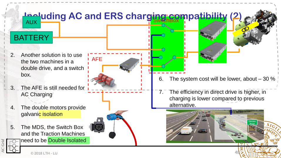
SwitchBoxIncluding AC and ERS charging compatibility (2)
BATTERY
AUX
AC
Gri
d
AFE
6. The system cost will be lower, about – 30 %
7. The efficiency in direct drive is higher, in
charging is lower compared to previous
alternative.
2. Another solution is to use
the two machines in a
double drive, and a switch
box.
3. The AFE is still needed for
AC Charging
4. The double motors provide
galvanic isolation
5. The MDS, the Switch Box
and the Traction Machines
need to be Double Isolated

© 2018 LTH - LU 49
AC+ERS System Cost
1 x 240/400 kW Cont/Peak + 200 kW OBC
OR
2 x 120/200 kW Cont/Peak + 120 kW AFE
© 2018 LTH - LU 50
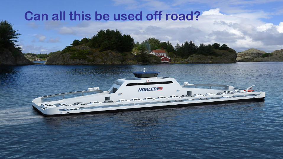
Can all this be used off road?

© 2018 LTH - LU 51
How to Provide a Big Ferry with Full Electric Drive !
• 10 min Dock / 20 min Transport
• Boat Battery:
– 1040 kWh, 20 tons, 50 Wh/kg
– 200 kWh / trip (20% DoD)
• 34 times a day
• Assume 100 k Cycles
• 2900 days = 8 years
– Charge at 1200 kW in 10 minutes (C=1.2)
• Shore Battery:
– 410 kWh
– Charge @ 400 kW in 20 min (C=1,0)
• 133 kWh/cycle, 32 % DoD
• Assume 30 k Cycles
• 1800 days = 5 years
– Discharge @ 800 kW in 10 min (C=2,0)
– PLUS Grid @ 400 kW for 10 min !400
80
0400
© 2018 LTH - LU 52
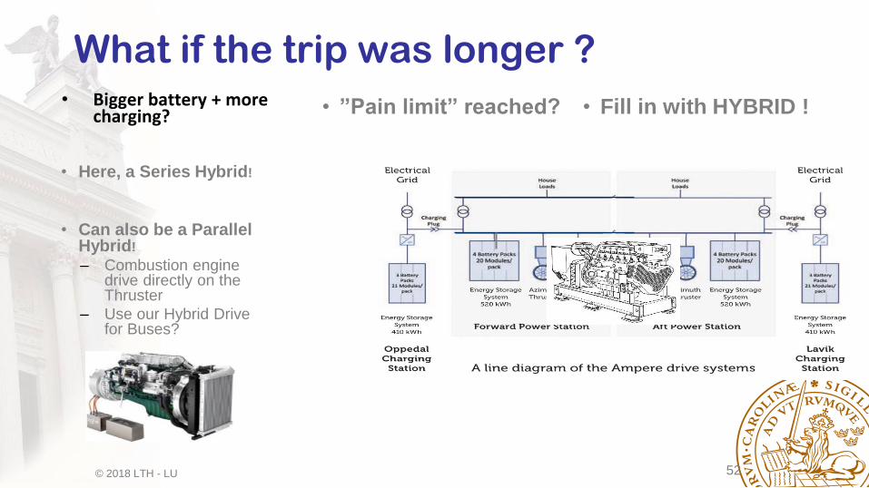
What if the trip was longer ?• Bigger battery + more
charging? • ”Pain limit” reached? • Fill in with HYBRID !
• Here, a Series Hybrid!
• Can also be a Parallel Hybrid!
– Combustion engine drive directly on the Thruster
– Use our Hybrid Drive for Buses?

© 2018 LTH - LU 53
And what if it was on land?
• No Hybrid Needed!
• Use Dynamic Charging to ”fill in”

© 2018 LTH - LU 54
Current Loading

© 2018 LTH - LU 55
Charging Solutions
BATTERY
AUX
AC
Gri
d
© 2018 LTH - LU 56
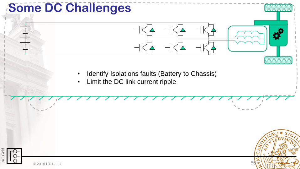
Some DC ChallengesA
C G
rid
• Identify Isolations faults (Battery to Chassis)
• Limit the DC link current ripple

© 2018 LTH - LU 57
The Ideal Drive
Chassis

© 2018 LTH - LU 58
Some parasitics ++
Parasitic and intentional 3x
Chassis
Zgnd
Zg
nd
Zg
nd
Phase to phase
Phase to core
© 2018 LTH - LU 59
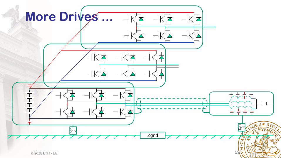
Chassis
Zgnd
Zg
n
d Zg
n
d
More Drives ...

© 2018 LTH - LU 60
The full system ...

© 2018 LTH - LU 61
Some conclusions:
1 A Complex circuit
2 A High Excitation
3 Complex harmonics
distribution

© 2018 LTH - LU 62
Potentials & Common Mode
Reference potential
Chassis
Zgnd
Zg
n
d Zg
n
d
Udc
Switching frequency

© 2018 LTH - LU 63
Chassis
Equivalent Circuit
Zgnd
Udc peak-to-peak
Swithing frequency + Harmonics
Zg
n
d Zg
n
d

© 2018 LTH - LU 64
Some more parasitics +++
Chassis
Zgnd
Zg
n
d
Zg
n
d
© 2018 LTH - LU 65
Chassis
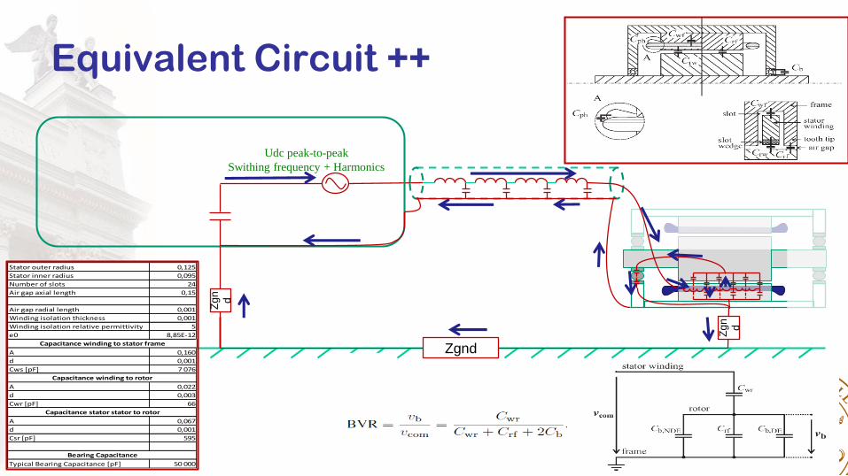
Equivalent Circuit ++
Udc peak-to-peak
Swithing frequency + Harmonics
Zg
n
d
Zg
n
d
Zgnd
Stator outer radius 0,125
Stator inner radius 0,095
Number of slots 24
Air gap axial length 0,15
Air gap radial length 0,001
Winding isolation thickness 0,001
Winding isolation relative permittivity 5
e0 8,85E-12
A 0,160
d 0,001
Cws [pF] 7 076
A 0,022
d 0,003
Cwr [pF] 66
A 0,067
d 0,001
Csr [pF] 595
Typical Bearing Capacitance [pF] 50 000
Capacitance winding to stator frame
Capacitance winding to rotor
Capacitance stator stator to rotor
Bearing Capacitance

© 2018 LTH - LU 66
Axial paths
© 2018 LTH - LU 67
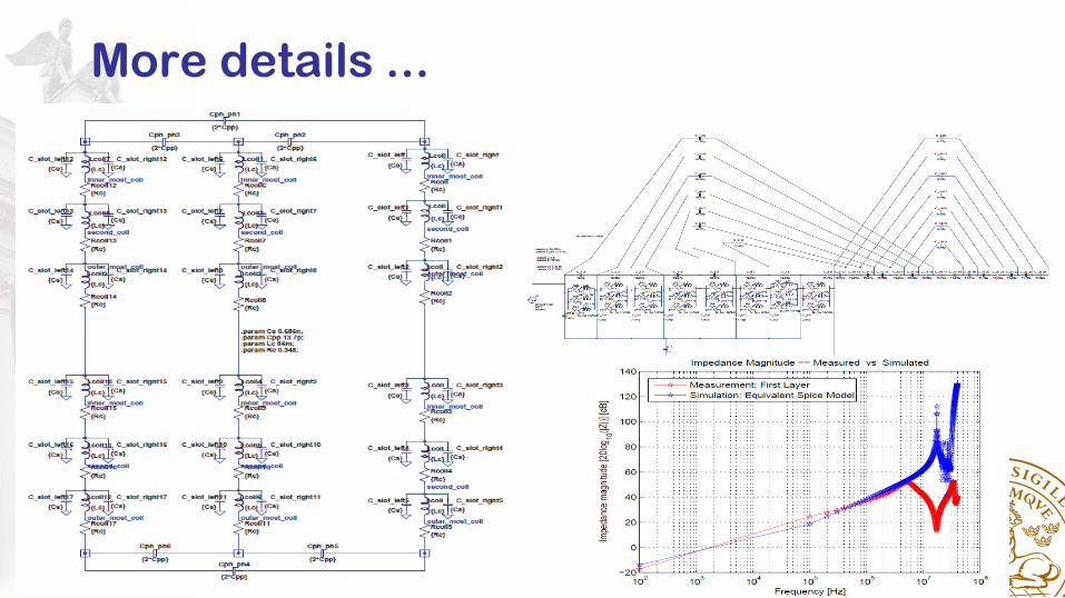
More details ...

© 2018 LTH - LU 68
Leakage current damping

© 2018 LTH - LU 69
Motor/Cable Impedance MismatchLeads to reflection and overvoltage up to 2x
© 2018 LTH - LU 70
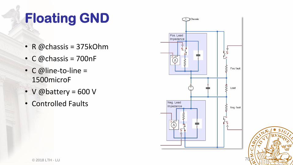
Floating GND
• R @chassis = 375kOhm
• C @chassis = 700nF
• C @line-to-line = 1500microF
• V @battery = 600 V
• Controlled Faults

© 2018 LTH - LU 71
Without Faults
• Switching Time = 2 s
• No Faults
• Voltages ~300±130 V
© 2018 LTH - LU 72
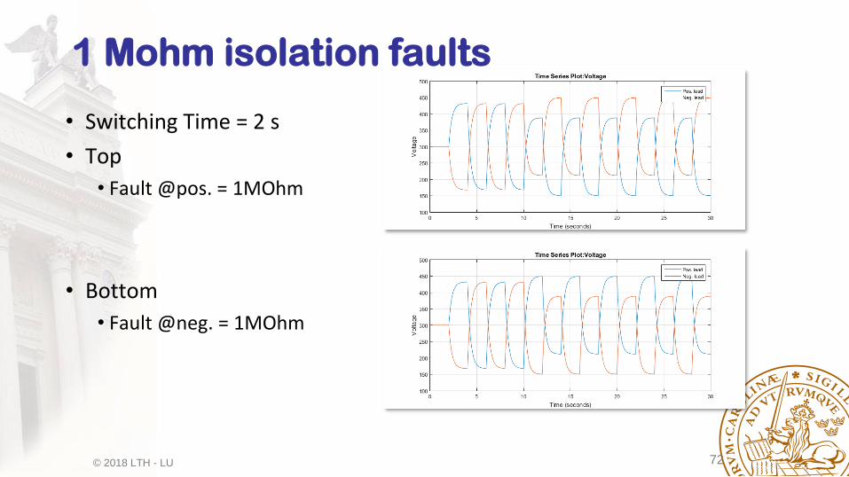
1 Mohm isolation faults
• Switching Time = 2 s
• Top
• Fault @pos. = 1MOhm
• Bottom
• Fault @neg. = 1MOhm
© 2018 LTH - LU 73
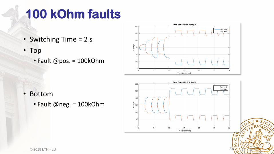
100 kOhm faults
• Switching Time = 2 s
• Top
• Fault @pos. = 100kOhm
• Bottom
• Fault @neg. = 100kOhm

© 2018 LTH - LU 74
Two different faults
• Switching Time = 2 s
• Top
• Faults = 1MOhm
• Bottom
• Faults = 100kOhm
© 2018 LTH - LU 75
Conclusions
• The Traction Motor Drive, and almost all other drives connnected to the Traction Battery, draw a Pulsed current from the Battery Circuit.
• The battery Ciruit contains A LOT of reactive components (Capacitors and Inductors)
• The harmonic spectrum from the drives connected to the Traction Battery, spread and interact through on the Traction Voltage System.
• This cause resonances, ageing and even malfunction on systems connected to the Traction Voltage System. A detalied understanding is needed.
• Parasitic components (inductances and capacitances) appear between the battery and the chassis, between the motor windings and the magnetic core of the motors, between power semiconductors and their heatsinks and between the power cables and their shields.
• These parasitics contribute to common mode currents (the same current in both battery cables AND/OR in all three motor cables) that cause ageing of insulation, bearings and possibly malfunction of Earth Fault Protectors (= Residual Current Detectors)
• Intentional impedance variations between the battery circuit and the chassis are used to detect isolations failures.