HX4 User Manual - NetGen Communications Manual . Version 1.4 August 2014 . ... Figure 3-72 – SIP...
88
® User Manual Version 1.4 August 2014 NetGen Communications, Inc. 1225 Northmeadow Pkwy Suite 114 Roswell, GA 30076 http://www.NetGenCommunications.com
Transcript of HX4 User Manual - NetGen Communications Manual . Version 1.4 August 2014 . ... Figure 3-72 – SIP...
®
User Manual Version 1.4 August 2014
NetGen Communications, Inc. 1225 Northmeadow Pkwy Suite 114 Roswell, GA 30076 http://www.NetGenCommunications.com

2

i
Amendment Records
Document Rev. 01 (September 2011 ) Document Rev. 02 (January 2012) Document Rev. 1.1 (May 2012) Document Rev. 1.2 (August 2012) Document Rev. 1.3 (February 2013) Document Rev. 1.4 (August 2014)

ii
Table of Contents
Amendment Records ......................................................................................................................................................... i
Table of Contents ........................................................................................................................................................... ii
List of Figures ................................................................................................................................................................. iv
List of Tables .................................................................................................................................................................. vi
1 Smart ATA Overview .................................................................................................................................................. 1 1.1 Fax Support ..................................................................................................................................................................................... 1 1.2 Functions and Features .................................................................................................................................................................... 1 1.3 Equipment Structure ........................................................................................................................................................................ 2 1.4 Connecting Smart ATA ................................................................................................................................................................... 4
2 Parameter Setting ......................................................................................................................................................... 5 2.1 Logging On ..................................................................................................................................................................................... 5
2.1.1 Obtaining the IP Address .................................................................................................................................................... 5 2.1.2 Logging On ......................................................................................................................................................................... 5 2.1.3 Permissions of Smart ATA Administrator .......................................................................................................................... 6
2.2 Buttons Used on the Smart ATA Management Interface ................................................................................................................ 7 2.3 Basic Configuration ......................................................................................................................................................................... 7
2.3.1 Status ................................................................................................................................................................................... 7 2.3.2 Network Configuration ....................................................................................................................................................... 8 2.3.3 System Configuration .......................................................................................................................................................... 9 2.3.4 SIP Configuration.............................................................................................................................................................. 10 2.3.5 MGCP Configuration ........................................................................................................................................................ 12 2.3.6 FoIP .................................................................................................................................................................................. 14 2.3.7 High Availability Configuration ....................................................................................................................................... 16
2.3.7.1 Configuring Active-Standby .................................................................................................. 17 2.3.7.2 Configuring Load Balancing .................................................................................................. 19
2.3.8 VLAN Configuration ........................................................................................................................................................ 22 2.3.8.1 Automatically Enabling VLAN .............................................................................................. 23 2.3.8.2 Procedure When the LLDP Message Carries a VLAN ID ....................................................... 23 2.3.8.3 LLDP Message with no VLAN ID ......................................................................................... 24 2.3.8.4 The LLDP Message ............................................................................................................... 24 2.3.8.5 Sent Message with a VLAN ID .............................................................................................. 25 2.3.8.6 GUI Configuration ................................................................................................................. 25 2.3.8.7 Manually Enabling VLAN ..................................................................................................... 26
2.3.8.7.1 Single VLAN .............................................................................................................. 26 2.3.8.7.2 Multiservice VLAN ..................................................................................................... 27
2.3.8.8 Acronyms .............................................................................................................................. 33 2.4 Routing .......................................................................................................................................................................................... 34
2.4.1 Dialing............................................................................................................................................................................... 34 2.4.2 Routing Table .................................................................................................................................................................. 36

iii
2.4.3 Application Examples of Routing Table ........................................................................................................................... 40 2.4.4 IP Table ............................................................................................................................................................................. 42
2.5 Line ............................................................................................................................................................................................... 43 2.5.1 Feature............................................................................................................................................................................... 43 2.5.2 Advanced .......................................................................................................................................................................... 46
2.6 Trunk ............................................................................................................................................................................................. 48 2.6.1 Trunk .................................................................................................................................. Error! Bookmark not defined. 2.6.2 Advanced .......................................................................................................................................................................... 50
2.7 Advanced Configuration ............................................................................................................................................................... 52 2.7.1 System ............................................................................................................................................................................... 52 2.7.2 Security ............................................................................................................................................................................. 54 2.7.3 White list ........................................................................................................................................................................... 55 2.7.4 Media stream ..................................................................................................................................................................... 56 2.7.5 SIP-related configuration .................................................................................................................................................. 57 2.7.6 Encryption ......................................................................................................................................................................... 59 2.7.7 Greeting ............................................................................................................................................................................. 61 2.7.8 Tones ................................................................................................................................................................................. 61 2.7.9 Service Feature Codes ....................................................................................................................................................... 62 2.7.10 System time ..................................................................................................................................................................... 65
2.8 Status ............................................................................................................................................................................................. 67 2.8.1 Call status .......................................................................................................................................................................... 67 2.8.2 Call history on Phone ........................................................................................................................................................ 67 2.8.3 Call history on Line ........................................................................................................................................................... 68 2.8.4 SIP message count ............................................................................................................................................................. 68
2.9 Logs ............................................................................................................................................................................................... 69 2.9.1 System status ..................................................................................................................................................................... 69 2.9.2 Call messages .................................................................................................................................................................... 70 2.9.3 System startup ................................................................................................................................................................... 71 2.9.4 Log management ............................................................................................................................................................... 71
2.10 Tools ............................................................................................................................................................................................ 72 2.10.1 Change password ............................................................................................................................................................ 72 2.10.2 Configuration maintenance ............................................................................................................................................. 72 2.10.3 Software upgrade ............................................................................................................................................................ 72 2.10.4 Restore factory settings ................................................................................................................................................... 73 2.10.5 TDM capture ................................................................................................................................................................... 73 2.10.6 Ethereal/Wireshark Capture ............................................................................................................................................ 74 2.10.7 Network diagnosis ........................................................................................................................................................... 74
2.11 Version information .................................................................................................................................................................... 75 2.12 Logout ......................................................................................................................................................................................... 75
3 Appendix ......................................................................................................................................................................76 3.1 Fix for SIP Devices Behind a NATed Device ............................................................................................................................... 76
3.1.1 Background...................................................................................................................................................................... 76 3.1.2 Problem Description ....................................................................................................................................................... 77 3.1.3 Solution ............................................................................................................................................................................ 78 3.1.4 Implementation ............................................................................................................................................................... 79
3.2 Using Smart ATA with Commetrex’ BladeWare .......................................................................................................................... 80

iv
List of Figures
Figure 1-1 SMART ATA Front Panel ................................................................................................................................................... 3 Figure 1-2 SMART ATA Back Panel ................................................................................................................................................... 3 Figure 1-3 SMART ATA Network ....................................................................................................................................................... 4 Figure 2-4 Login Interface for SMART ATA ....................................................................................................................................... 6 Figure 2-5 Status Interface .................................................................................................................................................................... 7 Figure 2-6 Network Configuration Interface ......................................................................................................................................... 8 Figure 2-7 System Configuration Interface ........................................................................................................................................... 9 Figure 2-8 SIP Configuration Interface ............................................................................................................................................... 11 Figure 2-9 MGCP Configuration Interface .......................................................................................................................................... 12 Figure 2-10 Fax configuration interface .............................................................................................................................................. 15 Figure 2-11 Active-Standby configuration page.................................................................................................................................. 18 Figure 2-12 Page to set registrar server ............................................................................................................................................... 19 Figure 2-13 Page to set DNS server ..................................................................................................... Error! Bookmark not defined. Figure 2-14 Page to disable PSTN failover .......................................................................................... Error! Bookmark not defined. Figure 2-15 Load balancing configuration page .................................................................................................................................. 20 Figure 2-16 Page to configure OPTIONS settings ............................................................................... Error! Bookmark not defined. Figure 2-17 Page to configure OPTIONS settings .............................................................................................................................. 21 Figure 2-18 System composition ......................................................................................................................................................... 23 Figure 2-19 Procedure of handling LLDP message carrying a VLAN ID ........................................................................................... 24 Figure 2-20 Procedure of handling the LLDP message with no VLAN ID ......................................................................................... 24 Figure 2-21 LLDP message ................................................................................................................................................................. 25 Figure 2-22 VLAN IDAdding a VLAN ID to the message to be sent ................................................................................................. 25 Figure 2-23 LLDP configuration interface for Smart ATA ................................................................................................................. 26 Figure 2-24 Configuring the single VLAN ......................................................................................................................................... 27 Figure 2-25 A data packet carrying a corresponding VLAN tag in the single VLAN mode ............................................................... 27 Figure 2-26 Configuring voice VLAN to work in mode 1 .................................................................................................................. 28 Figure 2-27 Configuring voice VLAN to work in mode 2 .................................................................................................................. 28 Figure 2-28 Configuring Management VLAN .................................................................................................................................... 29 Figure 2-29 Network environment ...................................................................................................................................................... 29 Figure 2-30 Configuring multiservice VLAN ..................................................................................................................................... 30 Figure 2-31 IP addresses of the device in multiservice VLAN ............................................................ Error! Bookmark not defined. Figure 2-32 SIP data packet carrying VLAN tag of the voice VLAN in the multiservice VLAN mode ............................................. 30 Figure 2-33 RTP data packet carrying VLAN tag of the voice VLAN in the multiservice VLAN mode ........................................... 31 Figure 2-34 HTTP data packet carrying VLAN tag of the voice VLAN in the multiservice VLAN mode ......................................... 31 Figure 2-35 VLAN configuration interface ......................................................................................................................................... 31 Figure 2-36 Configuration Interface for Dialing. ................................................................................................................................ 34 Figure 2-37 Configuration Interface for Routing Table....................................................................................................................... 36 Figure 2-38 Configuration Interface for IP Table ................................................................................................................................ 42 Figure 2-39 Configuration Interface for Subscriber Line Features ...................................................................................................... 43 Figure 2-40 Configuration Interface for Trunk Line Features ............................................................................................................. 45 Figure 2-41 Line Advanced Interface .................................................................................................................................................. 46 Figure 2-42 Configuration Interface for Trunk Line Features ............................................................................................................. 49 Figure 2-43 Trunk advanced interface ................................................................................................................................................. 51 Figure 2-44 NAT & Auto Provision interface ..................................................................................................................................... 52

v
Figure 2-45 Security configuration interface ....................................................................................................................................... 55 Figure 2-46 Media stream configuration interface .............................................................................................................................. 56 Figure 2-47 SIP-related configuration interface .................................................................................................................................. 58 Figure 2-48 ........................................................................................................................................... Error! Bookmark not defined. Figure 2-49 Encryption configuration interface .................................................................................................................................. 60 Figure 2-50 Greeting interface ............................................................................................................................................................ 61 Figure 2-51 Call-progress tone configuration interface ....................................................................................................................... 61 Figure 2-52 Function-key configuration interface ............................................................................................................................... 63 Figure 2-53 System time configuration interface ................................................................................................................................ 65 Figure 2-54 Interface of call status ...................................................................................................................................................... 67 Figure 2-55 Interface of call on Phone ................................................................................................................................................ 67 Figure 2-56 Interface of call on Line ................................................................................................................................................... 68 Figure 2-57 Interface of SIP message count ........................................................................................................................................ 68 Figure 2-58 System status Interface .................................................................................................................................................... 69 Figure 2-59 Call messages interface .................................................................................................................................................... 70 Figure 2-60 System startup interface ................................................................................................................................................... 71 Figure 2-61 Interface of Log management .......................................................................................................................................... 71 Figure 2-62 Interface for changing password ...................................................................................................................................... 72 Figure 2-63 Interface of restore factory capture ............................................................................................................................... 73 Figure 2-64 Interface of TDM capture ................................................................................................................................................ 73 Figure 2-65 Interface of Ethereal capture ............................................................................................................................................ 74 Figure 2-66 Interface of Network diagnosis ........................................................................................................................................ 74 Figure 2-67 Interface of help ............................................................................................................................................................... 75 Figure 3-68 – A NAT Example ........................................................................................................................................................... 76 Figure 3-69 – SIP with NAT ............................................................................................................................................................... 77 Figure 3-70 – SIP Call Example With NAT ..................................................................................................................................... 77 Figure 3-71 – SIP Call Example With NAT and ALG ........................................................................................................................ 78 Figure 3-72 – SIP Call Example (T.38) ............................................................................................................................................... 78 Figure 3-73 – SIP Example With Fix ............................................................................................................................................... 79

vi
List of Tables
Table 1-1 Common Configuration Combination of SMART ATA ....................................................................................................... 2 Table 1-2 Description of SMART ATA Front Panel............................................................................................................................. 3 Table 1-3 Description of SMART ATA Back Panel ............................................................................................................................. 3 Table 1-4 Description of Smart ATA Top Panel ................................................................................................................................... 3 Table 2-5 Default IP Address of Smart ATA ........................................................................................................................................ 5 Table 2-6 Default Passwords of Smart ATA ......................................................................................................................................... 6 Table 2-7 System Configuration Parameters ......................................................................................................................................... 9 Table 2-8 Codec Methods Supported by Gateways ............................................................................................................................. 10 Table 2-9 SIP Parameters .................................................................................................................................................................... 11 Table 2-10 MGCP Configuration Parameters ..................................................................................................................................... 12 Table 2-11 Fax configuration parameters ............................................................................................................................................ 15 Table 2-12 Network-Configuration Parameters.................................................................................... Error! Bookmark not defined. Table 2-13 LLDP configuration parameters ........................................................................................................................................ 26 Table 2-14 Description of parameters in the VLAN configuration interface ...................................................................................... 32 Table 2-15 Description of Dialing ....................................................................................................................................................... 34 Table 2-16 Dialing rules for the North American:............................................................................................................................... 35 Table 2-17 Routing Table Format ....................................................................................................................................................... 37 Table 2-18 Number Transformations .................................................................................................................................................. 38 Table 2-19 Routing Destination .......................................................................................................................................................... 39 Table 2-20 Configuration Parameters of Phone Features ..................................................................... Error! Bookmark not defined. Table 2-21 Configuration Parameters of Trunk Line Features ............................................................. Error! Bookmark not defined. Table 2-22 Parameters of system advanced configuration .................................................................................................................. 53 Table 2-23 Media stream configuration parameter .............................................................................................................................. 56 Table 2-24 SIP-related configuration parameter.................................................................................................................................. 58 Table 2-25 Phone configuration parameter .......................................................................................... Error! Bookmark not defined. Table 2-26 Line configuration parameter ............................................................................................. Error! Bookmark not defined. Table 2-27 Encryption configuration parameters ................................................................................................................................ 60 Table 2-28 Call-Progress Tone configuration parameters ................................................................................................................... 62 Table 2-29 Functional keys configuration parameter ........................................................................... Error! Bookmark not defined. Table 2-30 Parameters of call state ...................................................................................................................................................... 67 Table 2-31 Configuration parameters of Log management ................................................................................................................. 71 Table 2-32 Parameters of Resource ...................................................................................................... Error! Bookmark not defined.

Smart ATA Overview
NetGen Communications, Inc. Page 1
1 Smart ATA Overview
The SMART ATA series offers high-quality high-function low-density access devices used in residential, SOHO, and mobile-office VoIP applications. It also provides a reliable, low-cost, and flexible means to deploy converged-communication IP telephony for network operators and large enterprises. SMART ATA can be configured with connections to Ethernet and analog voice and fax terminals or with connections to Ethernet, analog voice-fax stations, and CO lines. Consisting of three models, the SMART ATA series can be either desktop or wall mounted. The highly compact hardware, with a MIPS 700-MHz CPU, supports the embedded Linux kernel and the application software that inherits from the New Rock Technologies (Shanghai) acclaimed MX design, delivering stable performance, high interoperability and compatibility, and rich features, including the patent-pending “Smart FoIP”, T.38 relay, and fax modems, from NetGen Communications, Inc. SMART ATA is a cost-effective entry-level VoIP device with the capability and quality only seen in much-higher-priced products. SMART ATA supports SIP and MCGP protocols, and includes: • PBX functions such as hunt group, second-stage dialing, intercom, caller ID (FSK/DTMF), call transfer,
call waiting, call hold, call barring, caller-ID restriction, hotline, corporate CRBT, three-way calling, ring group, and fax.;
• FXO (line)-related functions such as PSTN failover, gain control, busy-tone detection, voice prompt for inbound calls, and polarity reversal detection;
• Media-stream processing functions such as T.38 version 3 with V.34 fax relay, G.711/G.729 voice codec, and G.168 echo cancellation.
SMART ATA supports local and remote, distributed, and centralized management modes, including Web-access management,command-line configuration based on the Linux OS, auto-provisioning for firmware upgrades, and configuration management based on TFTP/FTP/HTTP, SNMPv2, TR069-based auto-configuration server (ACS).
1.1 Fax Support
SMART ATA is a low-density gateway/ATA/IAD that not only offers the service provider a full-function voice-fax ATA, IAD, and gateway, but also includes patented technology (US patent 9,094,419) that finally makes outbound FoIP calls as reliable as PSTN fax calls. Moreover, SMART ATA includes full support for T.38 version 3 with V.34, enabling it to send and receive faxes at twice the speed of non-V.34-capable devices. With SMART ATA, NetGen truly defines the next-generation ATA. NetGen has found that significant practical problems exist with SIP negotiations for FoIP calls in carrier-based networks. After much testing and analysis, we have developed, in partnership with Commetrex, “Smart FoIP,” which improves the reliability of fax-session establishment for media servers, ATAs, and access gateways. Since the technology increases the likelihood of a session remaining in G.711 fax pass-through mode if a re-Invite is late-arriving and, therefore, rejected, it also includes a major technology advance that eliminates PCM-clock synchronization problems, which are responsible for a large percentage of G.711 pass-through fax failures.
1.2 Functions and Features
Smart ATA provides support for the following:

SMART ATA Configuration Manual
Page 2 NetGen Communications, Inc.
• Analog telephones, PBX, facsimile machine, and POS terminals to the IP core network or the PSTN; • Service platforms to provide various telephone supplementary services; • SIP and MGCP; • Flexible configuration of phone/line interfaces; • Static IP address configuration or dynamic IP address obtained through DHCP and PPPoE; • G.711, G.729; • G.168 echo cancellation; • Capacity of up to 500 routing rules; • Intercom; • Digitmap; • Country-specific call-progress tone generation; • Second-stage dialing or voice prompt; • PSTN failover through line ports; • Security: IP filter, HTTPS, enable/disable GUI, SRTP, T.38 over SRTP; • DNS SRV; • VLAN; • RFC 6913; • Routing table; • T.38 version 3 fax relay with V.34; • Smart FoIP from Commetrex; • Polarity-reversal and busy-tone detection • Compatible with unified communication platforms, such as CallManager, OCS, and Asterisk • Multiple local and remote-maintenance & management modes such as Web, Telnet, Option 66
auto-provision, and TR069/TR104/TR106 client;.
1.3 Equipment Structure
Housed in a small plastic structure for desktop placement, the SMART ATA provides up to two phone/fax ports and two CO-trunk (FXO) ports. SMART ATA supports the following port configurations:
Table 1-1 Common Configuration Combination of SMART ATA
Models Number of Phone/fax Ports Number of Office Ports SMART ATA402E 2 0 SMART ATA 420E 0 2 SMART ATA 422E 2 2 SMART ATA 412E 2 1 SMART ATA 440E 0 4 SMART ATA 404E 4 0

Smart ATA Overview
NetGen Communications, Inc. Page 3
Figure 1-1 SMART ATA Front Panel
Table 1-2 Description of SMART ATA Front Panel
Name Description LED PWR Power indicator: Light-on indicates that the unit has been powered.
LED WAN Steady on indicates valid Ethernet link; flashing indicates Ethernet activity (receiving and/or transmitting)
LED Phone/Line Station or office-trunk indicator: Light-on indicates that it is in use.
Figure 1-2 SMART ATA Back Panel
Table 1-3 Description of SMART ATA Back Panel
Name Description Power 12 V DC input WAN 10/100 M Ethernet port for wide area (uplink) PC 10/100M Ethernet port for connecting PC or other local network element (downlink) Phone /Line Phone/fax or -trunk interface
There is an LED on the top panel that gives basic status information as follows.
Table 1-4 Description of Smart ATA Top Panel
Name Description Red, Steady On Ethernet cable no connected Red, Flashing Software or hardware alarm Red/Green alternating SIP registration has failed or timed out Green, Steady On SIP registration OK Green, Flashing Call active Off SIP registration is turned off

SMART ATA Configuration Manual
Page 4 NetGen Communications, Inc.
Figure 1-3 SMART ATA Network
1.4 Connecting Smart ATA
Connect your analog phones and fax terminals to the “Phone” jacks on the rear of the unit using RJ-11 telephone plugs. Connect one or two RJ-11 plugs and cables to the “Line” jacks. The other end of these cables will connect directly with your PSTN provider’s wall jack or your analog PBX’s station interface. Using an RJ-45 plug/cable, connect the WAN jack on the rear of the unit to the source of Internet connectivity such as a router or modem. Connect your PC or your internal LAN to the PC port using an RJ-45 cable. Connect the power adapter.

Basic Configuration
NetGen Communications, Inc. Page 5
2 Parameter Setting
2.1 Logging On
2.1.1 Obtaining the IP Address SMART ATA is a DHCP client by default, and automatically obtains an IP address on the LAN. Users can use the factory-default Smart ATA IP address if a DHCP address cannot be obtained (e.g. when connected directly with a computer).
Table 2-5 Default IP Address of Smart ATA
Type Default DHCP Service Default IP Address Default Subnet Mask SMART ATA
Enabled 192.168.2.218 255.255.0.0
• DHCP Used in Network • Users can dial “# #”to obtain the current Smart ATAIP address and version information of the Smart
ATA firmware using the telephone connected to the subscriber line (Phone interface) after the equipment is powered on.
• Fixed IP Address Used • If the DHCP service on the network is not available or Smart ATA is directly connected with a
computer, Smart ATA will use the factory-default IP address. • A user could fail to log in with the default IP address if the IP address of the user’s computer and the
default Smart ATA IP address are not at the same network segment. It is recommended that the IP address of the user's computer is changed to be identical with the same network segment of the gateway. For example, if the Smart ATAIP address is 192.168.2.218, it is recommended to set the computer’s IP address to any address at the network segment of 192.168.2.XXX).
• PPPoE (RFC 2516) Used o In “Basic > Network”, Smart ATAwill automatically obtain the WAN address returned by the
access network after the PPPoE service is started and the user name and password are set. Users can dial “# #”on the Smart ATA to receive the IP address and version of the firmware.
2.1.2 Logging On
Double-click the icon (or whatever browser you use) and enter Smart ATA’s IP address in the browser address bar (eg. 192.168.2.218); you can access the login interface for Smart ATA configuration by entering a password on the login interface.

SMART ATA Configuration Manual
Page 6 NetGen Communications, Inc.
Figure 2-4 Login Interface for SMART ATA
Both Chinese and English Languages are provided for the Web interface.
2.1.3 Permissions of Smart ATA Administrator Logged-on users are classified as “administrator” or “operator”. The default password is shown in Table 2-6, below. The password is shown in a cipher for security. The passwords are changed by clicking “Tools” on the navigation bar.
Table 2-6 Default Passwords of Smart ATA
Type Default Administrator Passwords (lowercase letters required)
Default Operator Password
SMART ATA voip voip
• The administrator can browse and modify all configuration parameters and modify log-in
passwords. • The operator can browse and modify a subset of the configuration parameters.
Multiple users can be logged in: If both an administrator and operator have logged in, the administrator may modify the configuration,
while the operator is limited to browsing; When multiple users with the same level of permission log in, the first may modify, while the others
may only browse.

Basic Configuration
NetGen Communications, Inc. Page 7
• The system will confirm timeout if users do not conduct any operation within 10 minutes after login. They
are required to log in again for continuing operations. • Upon completion of configuration, click the "Logout" button to return to the login page, so as not to affect
the login permission of other users.
2.2 Buttons Used on the Smart ATA Management Interface
“Submit” buttons are at the bottom of the configuration screens. Submit” Button: Submit configuration information. Users click “Submit” after the completion of parameter configuration on a page. A success prompt will appear if configuration information is accepted by the system; if a “The configuration takes effect after the system is restarted” dialog box appears, it means that the parameters are valid only after a system restart; it is recommended that users press the “Reboot” button on the top right corner to enable the configuration after completing all configuration changes.
2.3 Basic Configuration
2.3.1 Status After login, click “Basic > Status” tab to open the configuration interface, it displays the basic information of the device, like local ports, model, MAC address, and IP address, etc.
Figure 2-5 Status Interface

SMART ATA Configuration Manual
Page 8 NetGen Communications, Inc.
2.3.2 Network Configuration After login, click the “Basic > Network” tabs to open the configuration interface.
Figure 2-6 Network Configuration Interface
Table 2-7 System Configuration Parameters
Name Description Setup Methods for obtaining an IP address
Static: Static IP address is used; DHCP: Activate DHCP client and use the dynamic host configuration
protocol (DHCP) to set the IP addresses of the unit; PPPoE: PPPoE service is used.
IP address If “Static” or “DHCP” is selected for the network type but an address fails to be obtained, Smart ATA will use the IP address filled in here. If Smart ATA obtains an IP address through DHCP, the system will display the current IP address automatically obtained from DHCP. This parameter must be set due to no default value.
Netmask The subnet mask is used with an IP address. When Smart ATA uses a static IP address, this parameter must be entered; when an IP address is automatically obtained through DHCP, the system will display the subnet mask automatically obtained by DHCP. This parameter must be set due to no default value.
Gateway IP address The IP address of the “LAN Gateway”. When Smart ATA obtains an IP address through DHCP, the system will display the LAN address of the LAN Gateway automatically obtained through DHCP. This parameter must be set due to no default value.
DNS Obtain DNS server address automatically
Obtain DNS server information from DHCP server.
Use the following DNS server address
Use the DNS server filled in.
Primary Server If DNS service is activated, the network IP address of the preferred DNS server must be entered, and there is no default value.
Secondary Server If DNS service is activated, the network IP address of a standby DNS server can be entered here. It is optional and there is no default value.

Basic Configuration
NetGen Communications, Inc. Page 9
STUN STUN Method for obtain public IP address from STUN server
Enable Disable
Server IP address/Name
STUN server IP address Note: Default value is New Rock STUN server.
Server port STUN server port, default is 3478 Session interval STUN request interval for Smart ATA. Operations Trunk-registration: Smart ATA will re-register to SIP server without updated C
address in CONTACT/VIA/SDP field if public IP address changes. Trunk re-registration & NAT address updating: Smart ATA will re-register to SIP server with updated C address in CONTACT/VIA/SDP field if public IP address changes.
2.3.3 System Configuration After login, click “Basic > System” tab to open the configuration interface.
Figure 2-7 System Configuration Interface
Table 2-8 System Configuration Parameters
Name Description Codec Codecs supported by SMART ATA include G729A/20, PCMU/20, &
PCMA/20. This parameter must be set due to no default value. Several encoding methods can be configured in this item at the same time, separated with “,”. Smart ATA will negotiate with the SIP peer in the order from front to back when configuring the codec methods.

SMART ATA Configuration Manual
Page 10 NetGen Communications, Inc.
Name Description Hook-flash handling Smart ATA provides the following processing modes after detecting
hook flash from the station interfaces:
Internal: the hook flash event will be handled internally;
Server(RFC 2833): transmitting the hook flash to the service provider’s platform with RFC 2833;
Server (SIP INFO): transmitting the flash-off to the service provider’s platform with SIP INFO.
DTMF DTMF method Transmission modes of DTMF signal supported by Smart ATA include
Audio, RFC 2833 and SIP INFO. The default value is Audio.
RFC 2833: Separate DTMF signal from sessions and transmit it to the platform through RTP data package in the format of RFC2833;
Audio: DTMF signal is transmitted to the platform with sessions;
SIP INFO: Separate DTMF signal from sessions and transmit it to the platform in the form of SIP INFO messages.
Sending DTMF on-time
This parameter sets the on time (in ms) of DTMF signal sent from Line port. The default value is 100 ms. The duration time range is 20 ~ 3000 ms.
Sending DTMF off-time
This parameter sets the off time (ms) of DTMF signal sent from Line port. The default value is 100 ms. The interval time range is 30 ~ 1000 ms.
DTMF detection threshold
Minimum duration of effective DTMF signal. Its effective range is 32-96 ms. The greater the value is set, the more stringent the detection criterion.
DTMF detection adjust
Increase the value above during a call’s active phase to prevent false detection of DTMF. The valid values are 16, 32, and 48 in milliseconds.
Table 2-9 Codec Methods Supported by Gateways
Voice Codec Supported Bit Rate (Kbit/s) Time Intervals of RTP Package Sending (ms)
G729A 8 10/20/30/40 PCMU/PCMA 64 10/20/30/40
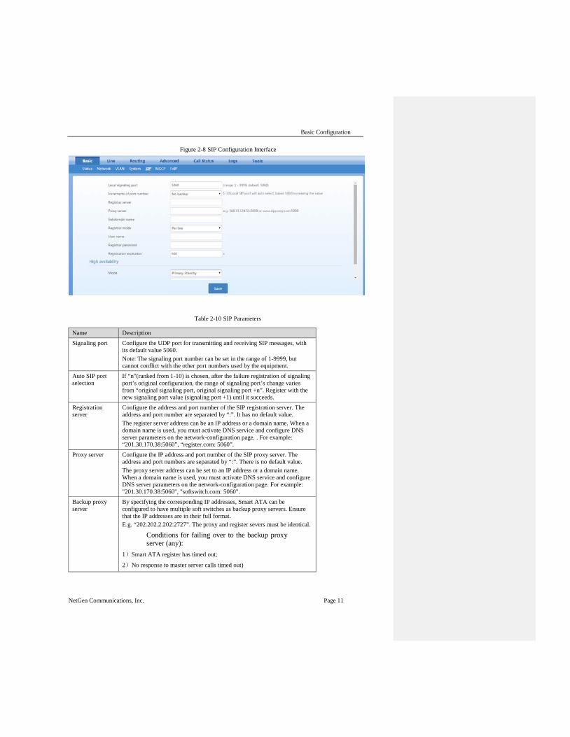
2.3.4 SIP Configuration After login, click “Basic > SIP” tab to open the SIP configuration interface.
Basic Configuration
NetGen Communications, Inc. Page 11
Figure 2-8 SIP Configuration Interface
Table 2-10 SIP Parameters
Name Description Signaling port Configure the UDP port for transmitting and receiving SIP messages, with
its default value 5060. Note: The signaling port number can be set in the range of 1-9999, but cannot conflict with the other port numbers used by the equipment.
Auto SIP port selection
If “n”(ranked from 1-10) is chosen, after the failure registration of signaling port’s original configuration, the range of signaling port’s change varies from “original signaling port, original signaling port +n”. Register with the new signaling port value (signaling port +1) until it succeeds.
Registration server
Configure the address and port number of the SIP registration server. The address and port number are separated by “:”. It has no default value. The register server address can be an IP address or a domain name. When a domain name is used, you must activate DNS service and configure DNS server parameters on the network-configuration page. . For example: “201.30.170.38:5060”, “register.com: 5060”.
Proxy server Configure the IP address and port number of the SIP proxy server. The address and port numbers are separated by “:”. There is no default value. The proxy server address can be set to an IP address or a domain name. When a domain name is used, you must activate DNS service and configure DNS server parameters on the network-configuration page. For example: "201.30.170.38:5060", "softswitch.com: 5060".
Backup proxy server
By specifying the corresponding IP addresses, Smart ATA can be configured to have multiple soft switches as backup proxy servers. Ensure that the IP addresses are in their full format. E.g. “202.202.2.202:2727”. The proxy and register severs must be identical.
Conditions for failing over to the backup proxy server (any):
1)Smart ATA register has timed out;
2)No response to master server calls timed out)

SMART ATA Configuration Manual
Page 12 NetGen Communications, Inc.
Name Description User agent domain name
This domain name will be used in INVITE messages. If it is not set here, Smart ATAwill use the IP address or domain name of the proxy server as the user-agent domain name. It has no default value. It is recommended that subscribers not use LAN IP address to set the domain name parameter.
Authentication mode
Smart ATAsupports three registration schemes: register per line, register per Smart ATA and Line Reg/GW Auth. The default value is register by line.
Register by line: authentication and register per line;
Register by gateway: authentication and register per gateway;
Line Reg/GW Auth: register per line, but authentication per gateway.
Registration expire
Valid time of SIP re-registration in
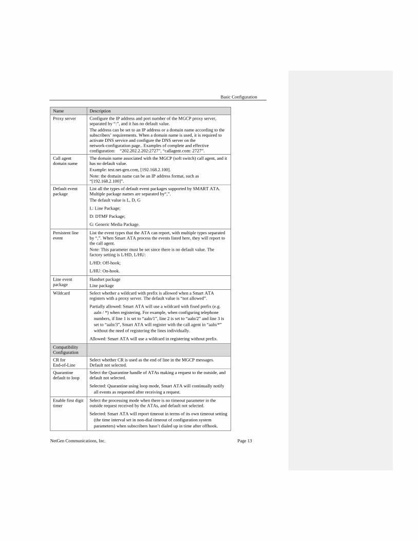
2.3.5 MGCP Configuration Smart ATA uses the SIP protocol by default. When Smart ATA is used in an MGCP application, set the relevant parameters here. Note: At this time, the MGCP implementation does not support the fax package. After login, click “Basic > MGCP” tab to open the configuration interface.
Figure 2-9 MGCP Configuration Interface
Table 2-11 MGCP Configuration Parameters
Name Description Signaling port Configure the UDP port for transmitting and receiving MGCP messages,
the default value is 2427. Note: The signaling port number can be set in the range of 1-9999, but cannot conflict with the other port numbers used by the equipment.
Basic Configuration
NetGen Communications, Inc. Page 13
Name Description Proxy server Configure the IP address and port number of the MGCP proxy server,
separated by “:”, and it has no default value. The address can be set to an IP address or a domain name according to the subscribers’ requirements. When a domain name is used, it is required to activate DNS service and configure the DNS server on the network-configuration page.. Examples of complete and effective configuration: “202.202.2.202:2727”, “callagent.com: 2727”.
Call agent domain name
The domain name associated with the MGCP (soft switch) call agent, and it has no default value. Example: test.net-gen.com, [192.168.2.100]. Note: the domain name can be an IP address format, such as “[192.168.2.100]”.
Default event package
List all the types of default event packages supported by SMART ATA. Multiple package names are separated by“,”. The default value is L, D, G
L: Line Package;
D: DTMF Package;
G: Generic Media Package.
Persistent line event
List the event types that the ATA can report, with multiple types separated by “,”. When Smart ATA process the events listed here, they will report to the call agent. Note: This parameter must be set since there is no default value. The factory setting is L/HD, L/HU:
L/HD: Off-hook;
L/HU: On-hook.
Line event package
Handset package Line package
Wildcard Select whether a wildcard with prefix is allowed when a Smart ATA registers with a proxy server. The default value is “not allowed”.
Partially allowed: Smart ATA will use a wildcard with fixed prefix (e.g. aaln / *) when registering. For example, when configuring telephone numbers, if line 1 is set to “aaln/1”, line 2 is set to “aaln/2” and line 3 is set to “aaln/3”, Smart ATA will register with the call agent in “aaln/*” without the need of registering the lines individually.
Allowed: Smart ATA will use a wildcard in registering without prefix.
Compatibility Configuration
CR for End-of-Line
Select whether CR is used as the end of line in the MGCP messages. Default not selected.
Quarantine default to loop
Select the Quarantine handle of ATAs making a request to the outside, and default not selected.
Selected: Quarantine using loop mode, Smart ATA will continually notify all events as requested after receiving a request.
Enable first digit timer
Select the processing mode when there is no timeout parameter in the outside request received by the ATAs, and default not selected.
Selected: Smart ATA will report timeout in terms of its own timeout setting (the time interval set in non-dial timeout of configuration system parameters) when subscribers hasn’t dialed up in time after offhook.
SMART ATA Configuration Manual
Page 14 NetGen Communications, Inc.
Name Description Using configured digit map
Select whether to activate the digit map configured by local gateway, and default value is not selected.
Using notify instead of 401/402
Set whether Smart ATA reports “off-hook events” to replace 401 messages in NTFY or report “on-hook events” to replace 402 messages in NTFY when responding to messages sent by the proxy server. Default: not selected.
Selected: Smart ATA will use NTFY message to replace 401 and 402 messages.
No name in default package
Select if a package name is included when Smart ATA replies to the default package, and default not selected.
Keep connection when on-hook
Select if Smart ATA actively cancels connection disconnect when subscriber is on-hook, and default not selected.
2.3.6 FoIP Effective configuration of the FoIP facility is critical. If your application directly peers with an IP service provider or carrier that supports T.38, you will need to select just T.38 in the FoIP section (see below), since the IP provider will generally require that calls initially begin in voice mode or G.711, which is selected in the “Initial Offer” section (PCMU/20). Then, if the network’s signaling is quick enough, the re-Invite to T.38 will be negotiated in time. Otherwise, with Smart FoIP, the call will stay in G.711 mode, and Smart FoIP’s patent-pending PCM clock-sync technology keeps it on track. If the carrier does not support T.38, check only G.711. Smart ATA has multiple operational modes, such as ATA and gateway. If you’re using it as a traditional gateway and there are no SIP peers that support V.34, check the 14400 bps box. Otherwise, click 33600 bps, the V.34 data rate. Unless you have a good reason to do so, we suggest you leave all the other selections at their defaults. After login, click the label of “Basic > FoIP” to open this interface.

Basic Configuration
NetGen Communications, Inc. Page 15
Figure 2-10 Fax configuration interface
Table 2-12 Fax configuration parameters
Name Description Codec for initial offer PCMU/20, PCMA/20. For outbound, we
recommend not putting T.38 in the initial offer as a general rule when using IP carriers.
Media ports These are the same defaults used for voice. FoIP modes For typical fax operation with networks that support
T.38, select only T.38, leaving the G.711 button unchecked. For G.711-only mode, check only G.711. Do not select both.
Speed Select the maximum-speed modem to use. Typically, you will select either 33600 bps to enable V.34 in T.38 mode, or 14400 bps to disallow V.34 fax.
Jitter Buffer Fax uses a fixed jitter buffer. Bigger is better to protect against PCM clock-sync problems, but the bigger the buffer the more delay inserted in the RTP path. (e.g., stick with the default.)
ECM Enable or disable ECM for T.38. ECM is always (automatically) selected for a V.34 fax.
Packet size In spite of what you see, the default is 40 msec. Signaling Redundancy A default of 4 means four redundant T.38 signaling
packets, for a total of five. Integrity of signaling data is critical for a successful fax. Since these are small packets, high levels of redundancy causes little increase in bandwidth.
Image Redundancy We recommend an image redundancy of one.

SMART ATA Configuration Manual
Page 16 NetGen Communications, Inc.
2.3.7 High Availability Configuration Smart ATA supports high availability with active-standby and load-balancing. Primary standby In this mode, one SIP proxy server (“SIP server”) functions as the primary server while another SIP servers functions as the standby servers. Either of the following conditions could trigger the failover operation of the gateway: • Not receiving a response to the OPTIONS message from the current SIP server to which the
gateway sends or receives call traffic; or • The administrator can manually switchover the gateway from the current SIP server to the
next available standby. The gateway will redirect call traffic to the newly designated proxy server in responding to the re-INVITE from the server. Active standby In this mode, one SIP proxy server (“SIP server”) functions as the primary server while additioinal SIP servers function as standby servers. Either of the following conditions could trigger the failover operation of the gateway: • Not receiving a response to the OPTIONS message from the current SIP server to which the
gateway sends or receives call traffic; or • Not receiving a response to the REGISTER/INVITE message from the current SIP server to
which the gateway sends or receives call traffic. • The administrator can manually switchover the gateway from the current SIP server to the
next available standby. The gateway will redirect call traffic to the designated proxy server in responding to the re-INVITE from the server. Load balancing In this mode, clustered SIP servers are all working in active status. Under the coarse-grained scheme, all endpoints behind of a gateway are allowed to register on one of the designated servers and under the fine-grained scheme the endpoints of a gateway are allowed to register on multiple servers, according to the administrator’s load-balancing plan. The following features are supported with load balancing: The gateway as a whole or endpoints search for the designated sever in the server cluster from a
a list of servers using REGISTER/INVITE message in forward-circular scheme. Server- failure detection is supported by the gateway sending OPTIONS to each server on
which the gateway or endpoints are registered. Upon the condition of no response to OPTIONS or REGISTER/INVITE, the gateway will
search for the next available server(s) for the gateway or endpoints and move the calls to it/them accordingly.
The gateway will redirect call traffic to the designated proxy server in responding to the re-INVITE from the server. The server cluster includes one primary SIP proxy server and up to five standby proxy servers under active-standby mode or six active servers under load-balancing mode. The address of the SIP server can be configured manually by the administrator or obtained through DNS SRV record.
Formatted: List Paragraph, Bulleted + Level:1 + Aligned at: 0.49" + Indent at: 0.78"
Formatted: List Paragraph, Bulleted + Level:1 + Aligned at: 0.49" + Indent at: 0.78"

Basic Configuration
NetGen Communications, Inc. Page 17
2.3.7.1 Configuring Primary-Standby
Enter the SIP trunk setting page, and click Basic > SIP > High availability configuration and choose Primary-standby, then submit.
Figure 2-11 Primary-Standby configuration page
The gateway supports two ways to obtain Backup SIP proxy address:
IP address
Domain name
Configuring the IP Address of SIP Servers:
Note: the IP address of the primary SIP server is configured on the top half of the SIP page.
Here are the steps to configure the IP addresses of the backup SIP proxy:
Step1 Ensure that active-standby feature is enabled.
Step2 Fill primary SIP server IP address in Registrar server, and then submit.
Step3 Click Add and fill the IP addresses for the standby SIP servers in Backup SIP proxy.
2.3.7.2 Configuring Active-Standby
Enter the SIP trunk setting page, and click Basic > SIP > High availability configuration and choose Active-standby, then submit.
SMART ATA Configuration Manual
Page 18 NetGen Communications, Inc.
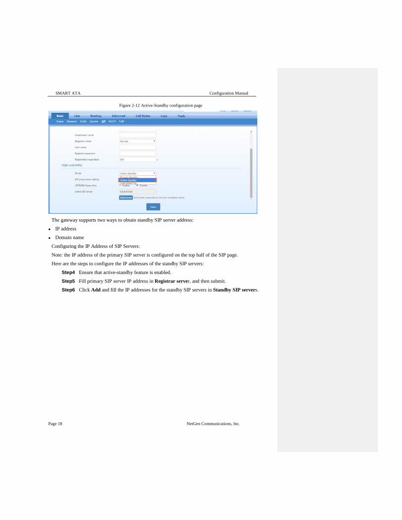
Figure 2-12 Active-Standby configuration page
The gateway supports two ways to obtain standby SIP server address:
IP address
Domain name
Configuring the IP Address of SIP Servers:
Note: the IP address of the primary SIP server is configured on the top half of the SIP page.
Here are the steps to configure the IP addresses of the standby SIP servers:
Step4 Ensure that active-standby feature is enabled.
Step5 Fill primary SIP server IP address in Registrar server, and then submit.
Step6 Click Add and fill the IP addresses for the standby SIP servers in Standby SIP servers.
Basic Configuration
NetGen Communications, Inc. Page 19
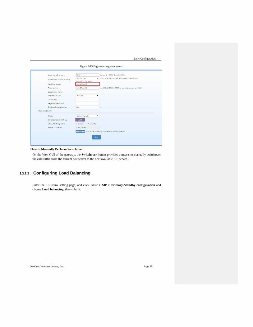
Figure 2-13 Page to set registrar server
How to Manually Perform Switchover:
On the Wen GUI of the gateway, the Switchover button provides a means to manually switchover the call traffic from the current SIP server to the next available SIP server.
2.3.7.3 Configuring Load Balancing
Enter the SIP trunk setting page, and click Basic > SIP > Primary-Standby configuration and choose Load balancing, then submit.

SMART ATA Configuration Manual
Page 20 NetGen Communications, Inc.
Figure 2-14 Load balancing configuration page
Then click Add to set the load balancing servers.
In the load balancing mode, the following timers need to be configured:
OPTIONS request period: The interval between receiving the response (200) from the SIP server to the previous OPTIONS and sending the next OPTIONS.
OPTIONS request timeout: The period since the sending of the last OPTIONS with no response by the SIP server.
In the load balancing mode, the following time must be configured:
REGISTER request timeout: The period from the sending of the first REGISTER with no response by the previous SIP server to the sending of REGISTER to the next SIP server.

Basic Configuration
NetGen Communications, Inc. Page 21
Figure 2-15 Page to configure Load balancing settings
All the SIP servers, on which the gateway or endpoints are registered on, will be listed in active server list.

SMART ATA Configuration Manual
Page 22 NetGen Communications, Inc.
2.3.8 VLAN Configuration Virtual Local Area Network (VLAN) is a type of communication technology that virtually divides a physical LAN/layer-2 network into multiple broadcast domains. Only hosts in the same VLAN can directly communicate without a router, so broadcast packets are restricted to the same VLAN, improving bandwidth utilization by, for example, segregating VoIP traffic, improving network security (e.g, a guest-only VLAN or finance-only VLAN). . VLAN technology identifies the VLAN information of a data packet by adding the VLAN tag field in the Ethernet frame header. When a gateway accesses a VLAN, configurations such as VLAN tags and priorities are required for the gateway. The following methods are used for configuring VLANs:
Manual configuration via a web-based GUI, requiring a restart after the configuration.
Automatic configuration: With Link Layer Discovery Protocol (LLDP) enabled, during startup Smart ATA automatically obtains VLAN configuration information via an LLDAP message, starts the VLAN, and obtains network information, such as its IP address, using the DHCP mode.
Smart ATA supports two VLAN modes: single VLANs and multiservice VLANs (including voice and management VLANs). Manual mode is used to configure single and multiservice VLANs. Automatic mode can configure only single VLANs. The following example uses the Smart ATA user interface (UI) to demonstrate how to manually configure VLANs with specific configurations and descriptions.
A restart is required to enable the VLAN configuration take effect. After a VLAN is configured, only PCs in the same VLAN can access the device. Smart ATA’s IP address used to log in to the GUI can be obtained by connecting a phone to an
FXS portand dialing "##". In the case of a single VLAN, the IP address of the single VLAN is voiced by the device; in the case of a multiservice VLAN, the IP address of the management VLAN is voiced.

Network Configuration
NetGen Communications, Inc. Page 23
2.3.8.1 Automatically Enabling VLAN
Figure 2-16 System composition
Network IP phone
The process consists of the following steps:
1. Smart ATA periodically sends an LLDP message to the switch with its device information. The sending interval is modifiable on the GUI interface. See Section 2 "GUI Configuration" for details.
2. The device receives an LLDP message from the switch, and parses the VLAN ID, Priority, and DSCP fields.
If the message carries a VLAN ID, the device enables VLAN, adds VLAN information to subsequent messages, and obtains network information such as an IP address via DHCP. If VLAN is also manually enabled on the GUI interface, its VLAN information will be replaced by the information that the device has obtained from the LLDP message. If the message does not carry a VLAN ID, the device checks whether VLAN is manually enabled. If it is, the ATA uses the VLAN information configured manually; otherwise, the device enters the non-VLAN communication status.
2.3.8.2 Procedure When the LLDP Message Carries a VLAN ID
The ATA only detects whether the LLDP message carries a VLAN ID upon startup. Once a VLAN ID is detected, the device enables the VLAN, adds VLAN information to subsequent outboundmessages, and obtains network information, such as an IP address, via DHCP. The device ignores any subsequent LLDP message with different VLAN ID. Figure 1-2 shows this procedure.

SMART ATA Configuration Manual
Page 24 NetGen Communications, Inc.
Figure 2-17 Procedure of handling LLDP message carrying a VLAN ID
2.3.8.3 LLDP Message with no VLAN ID
During startup period, if the ATA receives LLDP messages with no VLAN ID, it uses the VLAN information configured manually. Figure 1-3 shows the procedure.
Figure 2-18 Procedure of handling the LLDP message with no VLAN ID
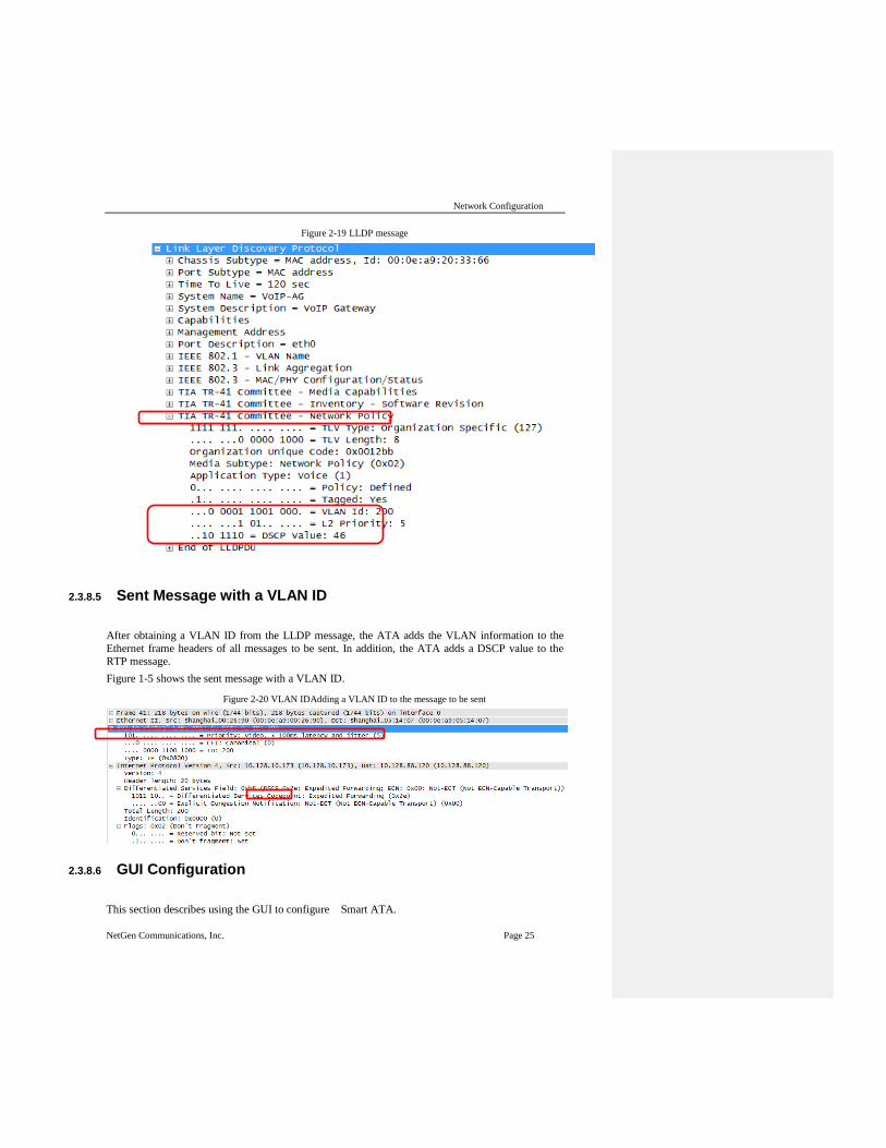
2.3.8.4 The LLDP Message
Upon receipt of an LLDP message, the device will check if the VLAN ID, Priority, and DSCP fields are included. Figure 1-4 shows the LLDP message.
Network Configuration
NetGen Communications, Inc. Page 25
Figure 2-19 LLDP message
2.3.8.5 Sent Message with a VLAN ID
After obtaining a VLAN ID from the LLDP message, the ATA adds the VLAN information to the Ethernet frame headers of all messages to be sent. In addition, the ATA adds a DSCP value to the RTP message. Figure 1-5 shows the sent message with a VLAN ID.
Figure 2-20 VLAN IDAdding a VLAN ID to the message to be sent
2.3.8.6 GUI Configuration
This section describes using the GUI to configure Smart ATA.

SMART ATA Configuration Manual
Page 26 NetGen Communications, Inc.
Click VLAN on the GUI interface, and confirm that the Activate option in the LLDP area is set to On.
Figure 2-21 LLDP configuration interface for Smart ATA
Table 2-13 LLDP configuration parameters
Parameter Name Description
Activate
On: Indicates that the LLDP is enabled. Then the device periodically sends LLDP messages, and parses received LLDP messages.
Off (default value): Indicates that the LLDP is disabled. The device does not send any LLDP messages, nor parses any received LLDP messages.
Packet interval This parameter specifies the interval at which LLDP messages are sent.. The value range is 5 to 3600 seconds. The default value is 30 seconds.
2.3.8.7 Manually Enabling VLAN
2.3.8.7.1 Single VLAN
In single-VLAN mode, all device services belong to the same VLAN. The device receives only data packets that carry the VLAN tag and includes the VLAN tag in all sent data packets. In this mode, the physical network port of the device has no separate address and shares the IP address of the VLAN interface.
GUI Configuration On the web interface, click Network, set the VLAN function to On, set Mode to Single VLAN, select the VLAN tag, and specify network information such as IP address if you choose static, as shown in Figure 1-7.

Network Configuration
NetGen Communications, Inc. Page 27
Figure 2-22 Configuring the single VLAN
Scenario Configure the ATA to work in single-VLAN mode with a corresponding VLAN tag of 200 and restart the device. Check that all data packets sent by the ATA carry a VLAN ID of 200, as shown in Figure 1-8. For an example of a packet capture, see SingleVlan.pcapng in the appendix.
Figure 2-23 A data packet carrying a corresponding VLAN tag in the single VLAN mode
2.3.8.7.2 Multiservice VLAN
In the case of the multiservice VLAN mode, the ATA can configure a VLAN tag; a priority for the voice service (SIP signaling and RTP media stream); and a management service (HTTP, Telnet, TR069, and SNMP). The ATA carries a different VLAN tag in data packets for different services. In this mode, the physical network port of the device can have a separate address or obtain an address from a non-VLAN network.
Configuring Voice VLAN In this mode, VLAN is used to segregate SIP, T.38, and RTP data packets. The voice VLAN of the device has the following two modes:
Mode 1 - Signaling (SIP) and media stream (RTP/T.38) are on the same VLAN
Mode 2 - Signaling (SIP) and media stream (RTP/T.38) are on different VLANs
In this mode, the voice VLAN can be configured with a separate IP address.
Mode 1 - SIP Signaling and Media on the same VLAN On the web interface, click VLAN, and ensure that the VLAN function is set to On and Mode is set to Multiservice VLAN. Select Mode 1 for Voice VLAN, enter the VLAN tag, and specify the network information such as IP address.

SMART ATA Configuration Manual
Page 28 NetGen Communications, Inc.
Figure 2-24 Configuring voice VLAN to work in mode 1
In this mode, the voice VLAN cannot be configured with a separate address but shares the IP address of the VLAN interface of the device.
Mode 2 - SIP Signaling and Media on Different VLANs
On the web interface, click VLAN, and ensure that the VLAN function is set to On, and Mode is set to Multiservice VLAN. Select Mode 2 for Voice VLAN, and specify VLAN tags for SIP and RTP.
Figure 2-25 Configuring voice VLAN to work in mode 2
Configuring Management VLAN The ATA includes VLAN tags configured in the management VLAN: HTTP, Telnet, TR069, and SNMP, in data packets of the four service types. On the web interface, click VLAN, and ensure that the VLAN function is set to On and Mode is set to Multiservice VLAN. Select Management VLAN, set the VLAN tag of the management service, and specify network information such as IP address. MTU (maxium transmission unit) should be left at 1500 unless there is a good reason to change it.

Network Configuration
NetGen Communications, Inc. Page 29
Figure 2-26 Configuring Management VLAN
Scenario Figure 1-12 shows the network environment. The ethereal ports for connecting the switch and Smart ATA are added to VLAN 200 and VLAN 300. The ethereal port for connecting the switch and SIP server is added to VLAN 300. The ethereal ports for connecting the switch to the PC (used for managing the ATA), TR069 server, and SNMP server are added to VLAN 200.
Figure 2-27 Network environment
Configure multiservice VLAN on the ATA: the voice VLAN uses mode 1, the VLAN tag is 300, the VLAN tag of the management VLAN is 200, and the IP address is obtained from the corresponding VLAN network using DHCP, as shown in Figure 1-13.

SMART ATA Configuration Manual
Page 30 NetGen Communications, Inc.
Figure 2-28 Configuring multiservice VLAN
1. Restart the ATA for the VLAN to take effect. 2. Use the PC belonging to VLAN 200 to log in to the web page. On the Basic > Status page, the IP address of each interface of the device can be viewed. From top to bottom: IP address of the device physical network port, IP address of the management VLAN, and IP address of the voice VLAN.
3. Enable the ATA to register with the SIP server and call an extension number on the SIP server. Check that VLAN tag 300 configured in the voice VLAN is carried in the SIP packet and RTP packet. For details about captured packets, see multiservicevlan.pcapng in Appendix.
Figure 2-29 SIP data packet carrying VLAN tag of the voice VLAN in the multiservice VLAN mode

Network Configuration
NetGen Communications, Inc. Page 31
Figure 2-30 RTP data packet carrying VLAN tag of the voice VLAN in the multiservice VLAN mode
4. Check that tag 200 of the management VLAN is carried in the HTTP packet in the PC management of the Smart ATA UI.
Figure 2-31 HTTP data packet carrying VLAN tag of the voice VLAN in the multiservice VLAN mode
Figure 2-32 VLAN configuration interface

SMART ATA Configuration Manual
Page 32 NetGen Communications, Inc.
Table 2-14 Description of parameters in the VLAN configuration interface
Parameter Description VLAN switch On: enable VLAN
Off: disable VLAN
VLAN Mode Single VLAN: All services of the device are on the same VLAN, and the device receives only data packets carrying the VLAN and includes the VLAN tag in all sent data packets.
Multi-service VLAN: The device can configure different VLAN information for the voice service (SIP signaling and RTP/T.38 media stream) and the management service (HTTP, Telnet, TR069, and SNMP) and includes a different VLAN tag in a data packets of a different service.
VLAN tag Tag of the VLAN. The value ranges from 1 to 1094. VLAN Qos Priority of the VLAN. The value ranges from 0 to 7. A large value indicates a higher
priority of a to-be-sent data packet. Voice VLAN VLAN to which the voice service (SIP signaling and RTP media stream) belongs.
None: disable the voice VLAN
Mode 1: SIP and RTP are on the same VLAN
Mode 2: SIP and RTP are on different VLANs
Management VLAN
Selected: enable the management VLAN
Deselected: disable the management VLAN
Network type Type for obtaining the IP address of the VLAN interface.
Static: set the IP address to a static IP address
DHCP: automatically obtain an IP address by using the DHCP protocol
IP address IP address of the VLAN interface Netmask Subnet mask of the VLAN interface Gateway IP address
IP address of the gateway of the VLAN interface
MTU Maximum Transmission Unit value of the VLAN interface. The value ranges from 576 to 1500. The default value is 1500.
Captured packet files relevant to the document:
Network Configuration
NetGen Communications, Inc. Page 33
2.3.8.8 Acronyms
DHCP – The Dynamic Host Configuration Protocol (DHCP) is a standardized networking protocol used on Internet Protocol (IP) networks for dynamically distributing network configuration parameters, such as IP addresses or interfaces and services. With DHCP, computers request IP addresses and networking parameters automatically from a DHCP server, reducing the need for a network administrator or a user to configure these settings manually.1 LLDP: Link-Layer Discovery Protocol -- LLDP is a vendor-neutral link-layer protocol in the Internet Protocol Suite used by network devices for advertising their identity, capabilities, and neighbors on an IEEE 802 local -area network, principally wired Ethernet. The protocol is formally referred to by the IEEE as Station and Media Access Control Connectivity Discovery specified in standards document EEE 802.1AB.2
Virtual LAN – In computer networking, a single layer-2 network may be partitioned through software to create multiple distinct broadcast domains that are mutually isolated so that packets can only pass between them via one or more routers; such a domain is referred to as a virtual local area network, virtual LAN or VLAN. Attached below is a packet capturing file for LLDP messages with VLAN ID.
1 Wikipedia 2 Wikipedia

SMART ATA Configuration Manual
Page 34 NetGen Communications, Inc.
2.4 Routing
2.4.1 Dialing After login, click “Routing > Dialing” tab to open the dialing rules interface as shown in Figure 2-10.
Figure 2-33 Configuration Interface for Dialing.
Dialing rules are used to determine if a received-number sequence has been completely entered for the purpose of terminating and acting on the received numbers. The effective use of dialing rules can =’reduce the connection time of telephone calls and improve the user’s experience. SMART ATA can have up to 60 rules. Each rule can hold up to 32 numbers and 38 characters. The total length of the dialing-rules table (the total length of all dialing rules) can be up to 2280 bytes. The “Critical Digit Timer” is run when there is a current match, but there could be a longer match. If an additional digit is entered prior to its expiration after a short match is found, the longer-match rule applies.
The following are descriptions of typical rules:
Table 2-15 Description of Dialing
Digit map Description “x” Represents any number between 0-9. “.” Represents more than one digit between 0-9. “##” “##” is a special dialstring for users to receive Smart ATA IP address
and version number of firmware by default. “x.T” Smart ATA will detect any length of telephone number starting with
any number between 0-9. Smart ATA will send the detected number when it has exceeded the dialing-end time/critical-digit time set in the system parameter configuration and has not received a new number.
“x.#” Any length of telephone number starting with any number between 0-9. If subscribers press # key after dial-up, Smart ATA will immediately terminate receiving digits and send all the numbers before # key.
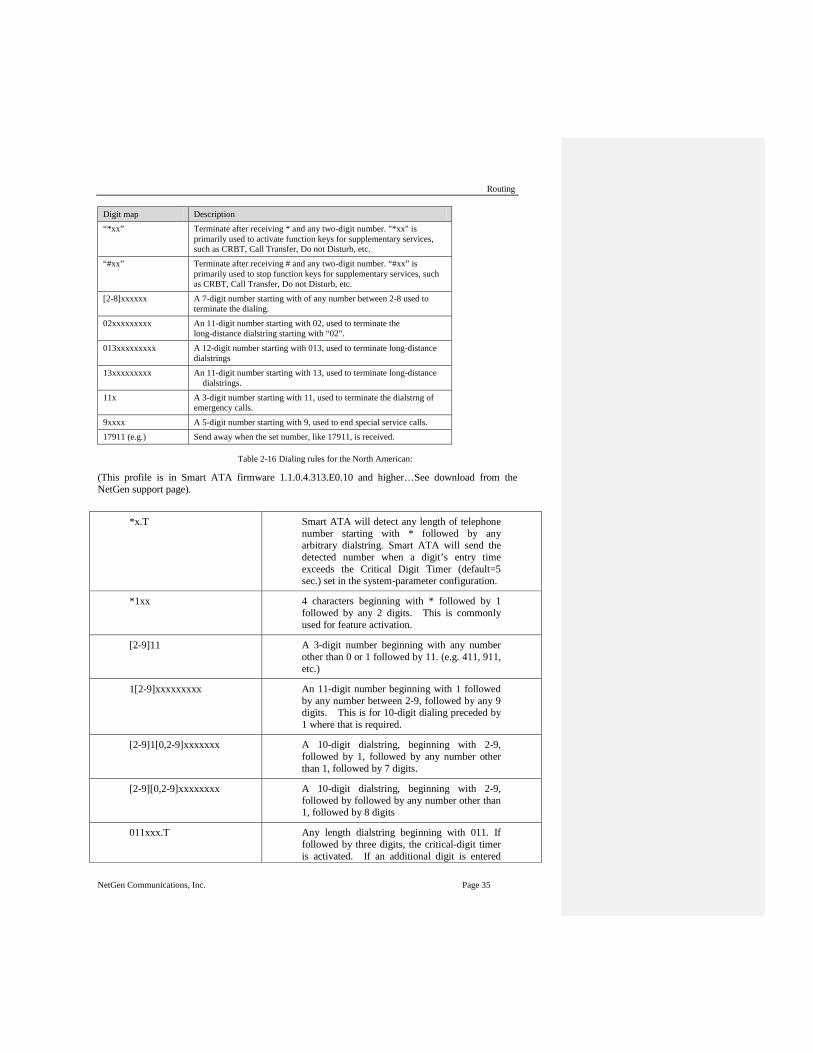
Routing
NetGen Communications, Inc. Page 35
Digit map Description “*xx” Terminate after receiving * and any two-digit number. "*xx" is
primarily used to activate function keys for supplementary services, such as CRBT, Call Transfer, Do not Disturb, etc.
“#xx” Terminate after receiving # and any two-digit number. “#xx” is primarily used to stop function keys for supplementary services, such as CRBT, Call Transfer, Do not Disturb, etc.
[2-8]xxxxxx A 7-digit number starting with of any number between 2-8 used to terminate the dialing.
02xxxxxxxxx An 11-digit number starting with 02, used to terminate the long-distance dialstring starting with “02”.
013xxxxxxxxx A 12-digit number starting with 013, used to terminate long-distance dialstrings
13xxxxxxxxx An 11-digit number starting with 13, used to terminate long-distance dialstrings.
11x A 3-digit number starting with 11, used to terminate the dialstrng of emergency calls.
9xxxx A 5-digit number starting with 9, used to end special service calls. 17911 (e.g.) Send away when the set number, like 17911, is received.
Table 2-16 Dialing rules for the North American:
(This profile is in Smart ATA firmware 1.1.0.4.313.E0.10 and higher…See download from the NetGen support page).
*x.T Smart ATA will detect any length of telephone number starting with * followed by any arbitrary dialstring. Smart ATA will send the detected number when a digit’s entry time exceeds the Critical Digit Timer (default=5 sec.) set in the system-parameter configuration.
*1xx 4 characters beginning with * followed by 1 followed by any 2 digits. This is commonly used for feature activation.
[2-9]11 A 3-digit number beginning with any number other than 0 or 1 followed by 11. (e.g. 411, 911, etc.)
1[2-9]xxxxxxxxx An 11-digit number beginning with 1 followed by any number between 2-9, followed by any 9 digits. This is for 10-digit dialing preceded by 1 where that is required.
[2-9]1[0,2-9]xxxxxxx A 10-digit dialstring, beginning with 2-9, followed by 1, followed by any number other than 1, followed by 7 digits.
[2-9][0,2-9]xxxxxxxx A 10-digit dialstring, beginning with 2-9, followed by followed by any number other than 1, followed by 8 digits
011xxx.T Any length dialstring beginning with 011. If followed by three digits, the critical-digit timer is activated. If an additional digit is entered

SMART ATA Configuration Manual
Page 36 NetGen Communications, Inc.
prior to the Critical Digit Timer expiring, the digit collection will continue until the inter-digit Timer expires. Used for international dialing.
xxxxxx.T 6 or more digits. The dialstring is sent after 6 digits when the Critical Digit Timer, which is run after 6 digits have been entered, expires. If an additional digits are entered prior to the Critical Digit Timer expiring, the digit collection will continue until the inter-digit Timer expires. Used for international dialing.
x.# An arbitrary-length dialstring terminated with a # or an
#xx A 2-digit entry preceded with a #.
## Used to cause the unit’s IP address and firmware release to be voiced.
2.4.2 Routing Table After login, click “Routing > Routing Table” tab to open the configuration interface.
Figure 2-34 Configuration Interface for Routing Table
Click “ ” to open the illustrative interface for routing configuration.
The routing table, with a 500-rule capacity, provides two functions: digit transformation and call-routing. Here are the general rules applied by Smart ATA when executing the routing table.
Rules must be filled out without any blank at the beginning of each line; otherwise the data can’t be validated even if the system prompts successful submittal. The routing table is empty by default. Smart ATA will point a call to the SIP proxy server when there is no matched rule for the call.

Routing
NetGen Communications, Inc. Page 37
The format of number transformation is Source Number Replacement Method
For example: “FXS 021 REMOVE 3” means remove the prefix 021 of the called number for calls from the FXS (Phone) port, where “FXS” is source, “021” is number, and “REMOVE 3” indicates the method of number transformation.
The format of routing rules is Source Number ROUTE Routing Destination
For example: “IP 800[0-3] ROUTE FXO 1-2” means route calls from IP with called number between 8000~8003 to FXO (Line) port in a sequential selecting order of 1, 2 (Line Port 2 is selected when Line Port 1 is busy and so on).
Detailed definitions of source and number, number transformation methods and routing destination are shown below.
Table 2-17 Routing Table Format
Name Description Source There are three types of source: IP, FXS (Phone/fax) and FXO
(Line). Among them, IP source can be any IP address and is denoted by “IP”; “IP [xxx.xxx.xxx.xxx]” is used to denote a specific IP address; “IP [xxx.xxx.xxx.xxx: port]” is used to denote specific IP address with port number. FXS(Phone) and FXO(Line) ports can be any port, represented with “FXS” or “FXO”; special lines can be represented with FXS or FXO plus the port number, e.g. FXS1, FXO2 or FXS [1-2], etc.
Number It could be a calling party number with the form of CPN + number,such as CPN6034340633 or a called party number with the form of number. The number may be denoted with digit 0-9,"*",".","#"," x ", etc., and uses the same regular expression as that of dialing rules. Here are examples of the form of number:
Designate a specific number: eg.114,6122700;
Designate a number matching a prefix: such as 61xxxxxx. Note: the matching effect of 61xxxxxx is different from that of 61x or 61. Number matching follows the principle of “minimum priority matching ”
Specify a number scope. For example, 268[0-1,3-9] specifies any 4-digit number starting with 268 and followed by a digit between 0-1or 3-9;
Note: Number matching follows the principle of “minimum matching”. For example: x matches any number with at least one digit; xx matches any number with at least two-digit; 12x matches any number with at least 3-digit starting with 12.

SMART ATA Configuration Manual
Page 38 NetGen Communications, Inc.
Table 2-18 Number Transformations
Processing Mode Description and Example KEEP Keep number. A positive number behind KEEP means to keep several
digits in front of the number; a negative number means to keep several digits at the end of the number. Example: FXS 17704497704 KEEP -7 Keep the last 7 digits of the called number 17704497704 for calls from FXS (Phone). The transformed called number is 4497704.
REMOVE Remove number. A positive number following REMOVE means to remove the first several digits of the number; a negative number means to remove the latter several digits of the number. For example: FXS 17704497704 REMOVE 4 Remove 1770 of the called number beginning with 1770 for calls from FXS (Phone).
REMOVE Remove hyphens from a dialstring, e.g. 1-xxx-xxx-xxxx => 1xxxxxxxxxx. IP CPN1-XXX-XXX-XXXX REMOVE 1 POS 1 <= remove the first hyphen IP CPN1-XXX-XXX-XXXX REMOVE 1 POS 4 <= remove the second hyphen IP CPN1-XXX-XXX-XXXX REMOVE 1 POS 7 <= remove the third hyphen Each digit-adjust rule can only perform one operation, i.e. add, delete, replace, etc., but you can add multiple rules together. POS in the rule specifies from which position to start the change, starting with 0,1,2... No POS (position) is interpreted as 0, which is the first digit.
ADD Add prefix or suffix to number. A positive number behind ADD is the prefix; a negative number is suffix. Example 1: FXS1 CPNX ADD 021 FXS2 CPNX ADD 010 Add 021 in front of calling numbers for calls from FXS (Phone) port 1; add 010 in front of calling numbers for calls from FXS (Phone) port 2. Note: CPNX denotes to any calling party number. Example 2: FXS CPN6120 ADD -8888 Add 8888 at the end of the calling number starting with 6120 for calls from an FXS (Phone/fax) port.
REPLACE Number replacement. The replaced number follows REPLACE. Example: FXS CPN88 REPLACE 2682000 Replace the calling number beginning with 88 for calls from FXS (Phone) port with 2682000.
REPLACE Another use of REPLACE is to replace the specific number based on another number associated with the call. For example, replace the calling number according to the called number. Examples: FXS 12345 REPLACE CPN-1/8621 FXS CPN13 REPLACE CDPN0/0 For calls from FXS (Phone) ports with called party number of 1234, remove one digit at the end of the calling number and add 8621; for calls from FXS (Phone) ports with calling party number starting with 13, add 0 at the beginning of the called number.

Routing
NetGen Communications, Inc. Page 39
Processing Mode Description and Example END or ROUTE End-of-number transformation. From top to bottom, number
transformation will be stopped when END or ROUTE is encountered; Smart ATA will route the call to the default routing upon detecting END, or route the call to the designed routing after detecting ROUTE. Example 1: FXS 12345 ADD -8001 FXS 12345 REMOVE 4 FXS 12345 END Add suffix 8001 to the called number starting with 12345 for calls from FXS (Phone) ports, then remove four digits in front of the number to end number transformation yielding 58001. Example 2: IP[222.34.55.1] CPNX. REPLACE 2680000 IP[222.34.55.1] CPNX. ROUTE FXS 2 For calls from IP address 222.34.55.1, calling party number is replaced by 2680000, and then the call is routed to FXS (Phone) port 2 with the new calling party number.
CODEC Designate the use of a codec, such as PCMU/20/16, where PCMU denotes G.711, /20 denotes RTP packet interval of 20 milliseconds, and /16 denotes echo cancellation with 16 milliseconds window. PCMU/20/0 should be used if echo cancellation is not required to activate. Example: IP 6120 CODEC PCMU/20/16 PCMU/20/16 codec will be applied to calls from IP with called party number starting with 6120.
RELAY Insert prefix of called party number when calling out. The inserted prefix number follows behind RELAY. Example: IP 010 RELAY 17909 For calls from IP with called party number starting with 010, digit stream 17909 will be outpulsed before the original called party number is sent out.
Table 2-19 Routing Destination
Destination Description and Example ROUTE NONE Calling barring. (also known as “blacklist”)
Example: IP CPN[1,3-5] ROUTE NONE Bar all calls from IP, of which the calling numbers start with 1, 3, 4, and 5.

SMART ATA Configuration Manual
Page 40 NetGen Communications, Inc.
Destination Description and Example ROUTE FXS Route a call to FXS (Phone) ports.
Example 1: IP 800[0-3] ROUTE FXS 1-2 Select a port in sequential order. Note: 800[0-3] denotes to the UDP ports ranging from 8000 to 8003. Example 2: IP 800[0-3] ROUTE FXS 1 Point this call to FXS (Phone) port 1. Example 3: IP 800[0-3] ROUTE FXS 1-2/R Select a port in round robin order Example 4: IP 800[0-3] ROUTE FXS 1-2/G Select all idle ports and provide ringing.
ROUTE FXO Route a call to FXO (Line) port. Example 1: IP x ROUTE FXO 1-2
Select a port in sequential order.
Example 2: IP 800[0-1] ROUTE FXO 1-2/R
Select a port in round robin order. ROUTE IP Route a call to the SIP proxy server
Example: FXS 021 ROUTE IP 228.167.22.34:5060 228.167.22.34:5060 is the IP address of the platform.
2.4.3 Application Examples of Routing Table Some typical functions that can be realized by the routing table are provided in this section (Take SMART ATA-2S/2 as an example):
1. One Phone with Two Numbers 2. Hunt Group 3. Outbound Call Barring 4. FXO (Line) Port Hunting for Outbound Call
One Phone with Two Numbers
A handset connected to the SMART ATA can be configured with two numbers for one phone with two numbers. For example, port Phone1 is set with PSTN number 612-2701 and extension number 1001 for internal calling
Routing Setting
FXS 1001 ROUTE IP 127.0.0.1:5060

Routing
NetGen Communications, Inc. Page 41
IP 1001 ROUTE FXS 1
Description: Send a call with a called number starting with 1001 from FXS (Phone) port to port 5060 of gateway’s local IP; Send a call with a called number starting with 1001 and from any IP to the FXS (Phone) port 1.
Configuration number of Phone1 itself is 612-2701, so the call of this number is not required to write specialized routing.
Hunt Group
A hunt group can be associated with a set of FXO (Line) ports, and an inbound call from IP or FXS (Phone) ports can be routed to a hunt group.
Routing Setting: Send an inbound call from the IP trunk or an FXO line in a sequential way to the phone set on the 1st or 2nd FXS (Phone) port.
FXO x ROUTE IP 127.0.0.1:5060
IP x ROUTE FXS 1-2
Description: Send all calls from the FXO (Line) port to port 5060 of gateway’s local IP; Send all inbound calls from any IP (inside and outside) to the 1st or 2nd FXS (Phone) port in sequence. Namely, the first FXS (Phone) port is selected firstly when it is available; otherwise the 2nd port is selected.
Outbound Call Barring
Restrict users from dialing certain telephone numbers, such as an international call. Examples are as follows:
• Routing Setting Description
• FXS[1] 0 ROUTE NONE
A calling starting with 0 is barred from dialing using the phone set at Phone1 port.
• FXS[1-2] 00 ROUTE NONE
A calling starting with 00 is barred from dialing at 1-2 Phone ports.
• FXS CPN2 ROUTE NONE
The telephone whose calling number starts with 2 at a Phone port is barred to call out.
Line-Port Hunting for Outbound Calls
Routing Setting:
FXS x ROUTE IP 127.0.0.1:5060
IP x ROUTE FXO 1-2
Description: Send all calls from FXS (Phone) ports to UDP 5060 of the Smart ATA (this port must be consistent with the local port in “Configuring SIP”); Send calls from IP to FXO (Line) ports in sequential order.
Send all calls from FXS (Phone) ports to UDP 5060 of the Smart ATA (this port must be consistent with the local port in “Configuring SIP”); Send calls from IP to FXO (Line) ports in sequential order.

SMART ATA Configuration Manual
Page 42 NetGen Communications, Inc.
2.4.4 IP Table After login, click “Routing > IP Table” tab to open the configuration interface.
Figure 2-35 Configuration Interface for IP Table
This table is designed to increase Smart ATA’s security. Administrators can add the authorized IP addresses to this table, and Smart ATA will only process the information from authorized IP addresses. If the IP table is empty, Smart ATA will not perform IP address-based message filtering.
For example: Smart ATA will only process messages from 202.96.209.133 after adding 202.96.209.133 to its IP table.

Phone/Line
NetGen Communications, Inc. Page 43
2.5 Line
2.5.1 FXS Phone number After login, click “Line > Phone number” tab to open the configuration interface.
Figure 2-36 Configuration Interface for FXS Phone number
2.5.2 Feature After finishing number setting, click “Line > Feature” tab to open the configuration interface.
Figure 2-37 Configuration Interface for Subscriber Line Features
Table 2-20 Configuration Parameters of Phone Features
Name Description Phone number Display the Telephone Number of this line. Users can input or change the
telephone number here. Display name Fill in the name associated with this port. Registration Select if this line is required to register with a softswitch. This is selected as
default. User name If “Registration” is selected, users must enter the authentication username
for registration of this line here. Password If “Registration” is selected, users must enter the authentication password
for registration of this line here.

SMART ATA Configuration Manual
Page 44 NetGen Communications, Inc.
Name Description Note: The following features are valid only in SIP protocol. When the Smart ATAuse MGCP protocol, features are controled by the proxy server without the need for setting on the gateway. Hot line Select if Smart ATA is required to automatically dial out the hotline number
after off-hook. By default, hot line is disabled.
Disable: Close this feature.
Immediate mode: Automatically dial out the hotline number after off-hook. Delay mode: Automatically dial out the hotline number when the off-hook is
timeout with a time delay of 5 seconds.
CRBT (Color ring back tone)
CRBT stands for Color Ring Back Tone. Set if CRBT is activated, that is, provide prepared audio package as ring back tone. Note: it is required to set the CRBT file download platform. This is not selected by default. SMART ATA supports two CRBT storage modes: on-system (stored in the flash memory) and run-time download (from FTP server). The length of tone in both modes are described as follows: On-system:
SMART ATA: No more than 20 seconds in G.729 format (fring1.dat) Run-time download:
SMART ATA: Up to 20 tone files, a maximum of 1250 seconds in G.711 format.
Note: Tone files are stored in the flash memory and Smart ATA automatically downloads the tone files from FTP server after power on.
Speed dials Select if the Speed dials is activated on this line. By default, this is not selected.
Call forwarding Select if Call forwarding is activated on this line. By default, it is not selected.
Forking Select to activate Forking. Forking allows the Smart ATA to initiate a call to another telephone terminal while ringing on this line terminal. Either terminal may answer, terminating ringing on the other terminal.
Release control by caller
Select if the call release is controlled by the caller. By default, this is not selected.
Selected: The Smart ATA will immediately release the call upon caller hanging up; the Smart ATA will not release the call after the called party hanging up as long as the caller is still off-hook until timeout (60 seconds by default);
Unselected: The Smart ATA will immediately release the call upon either party hanging up the call.
Loop open disconnect
Select to stop power supply to FXS port when call finished.
Call waiting Select if Call waiting is activated on this line. By default this is not selected. Call hold Select if Call Hold is activated on this line. By default this is not selected.
Note: If this function is activated, Smart ATA will automatically activate Call Transfer (Either party may transfer the current call to a third party).
Call transfer Select if Call Transfer is activated on this line. By default, this is not selected. When A calls B, B picks up the call and transfers the call to C, Note: The call hold must be activated before caller transfer.
Caller ID display
Set whether Caller ID display is activated on this line. By default, this is selected. Note: In addition to number display, the Caller ID can display the names of incoming calls as long as terminal equipments support.

Phone/Line
NetGen Communications, Inc. Page 45
Name Description Caller ID restriction
Set whether the number of this telephone is sent to the called party. This feature requires the support of the softswitch. By default this is not selected.
Outgoing call barring
Select if outgoing calls are barred on this line. By default, this is not selected.
DND (Do not disturb)
Select if “Do Not Disturb” is enabled on this line. By default, this is not selected.
Maintenance Select if the line is set to maintenance status, in which the FXS port no longer supplies current to the phone. By default, this is not selected.
Polarity reversal Select if reverse-polarity signal is activated on this line. By default, this is not selected. Note: Smart ATA will provide reverse polarity signal when the phone is connected after this feature is activated.
Subscribe MWI Select if voice mail service is activated, and, by default, this is not selected. (Also see “MWI Re-subscription timer” on page “Advanced > SIP”.)
Note:Skip this section if your Smart ATA does not have an FXO (office) Line port.
After login, click “Phone/Line > Line n” tab to open the configuration interface.
Figure 2-38 Configuration Interface for Trunk Line Features
Configuration Parameters of Trunk Line Features
Name Description Line number Display phone number associated with the trunk. Registration Select if this trunk registers with the SIP registration server. By default,
this is selected. Password If “Registration” is selected, the authentication password for register of
this line must be entered here.

SMART ATA Configuration Manual
Page 46 NetGen Communications, Inc.
Name Description Note: The following features are valid only in SIP protocol. When the Smart ATAuse MGCP protocol, the control of all call services is provided by the proxy server without the need of these setting. Inbound call handling
Smart ATA provides three scenarios for handling incoming calls on the FXO turnk Line ports (Line Port):
“Binding”: When a telephone call comes to the Line port, Smart ATA will route the call to a Phone port according to the DID number bound with the port. Note: Setting a number to be bound is required or this setting is invalid.
“Second-stage dialing”: When a telephone call comes to the Line port, the Smart ATA will provide the second dial tone and route the call according to the extension number entered. Note: dialing tone or voice prompt file can be changed by user.
“Direct”: Smart ATA will route the incoming call on FXO port n to FXS port n
Polarity reversal detection
If a PSTN line supports reverse polarity, make the selection here. By default, this is not selected.
Caller ID detection Select if the detection function of caller ID for this Line port is enabled. By default, this is selected.
Outbound blocking Select if this Line port bars outgoing call service to the PSTN. By default, this is not selected.
Echo cancellation Select if echo cancellation is enabled for this FXO (Line).By default, this is selected.
Delay sending 200 OK
After making an outgoing call from a Line port, Smart ATA will send a 200 OK message to the SIP peer on the IP port with a delay if this parameter is selected. If unselected, the system sends a 200 OK message to the SIP peer after off hook on the Line port. Also see “Answer delay” on page “Advanced > line”.
2.5.3 Advanced
Click “Line > Advanced” tab to open the advanced configuration interface.
Figure 2-39 Line Advanced Interface

Advanced Configuration
NetGen Communications, Inc. Page 47
Table 2-21 Configuration Parameters of Advanced phone Features
Title Explanation Gain to IP Set the voice volume gain toward the IP side, the default is 0. Taking
decibel as the unit, setting range is -3 ~ +3 decibels. -3 means declining of 3 decibels; +3 denotes the amplification of 3 decibels.
Gain to terminal Set the voice volume gain toward (Phone) port side, the default is -3. Taking decibel as the unit, setting range is -6 ~ +3 decibels. -3 means declining of 3 decibels; +3 denotes the amplification of 3 decibels.
Impedance Select the parameter of FXS (Phone) port line impedance and the default value is 600 ohm. The optional values as below:
Complex
600(ohm)
900(ohm)
Min.hookflash Used by the Smart ATAto detect Hook Flash event, the default is 75 milliseconds. The Smart ATAwill ignore any flash that fall short of the shortest flash time. Generally, this value should not be less than 75 milliseconds.
Max.hookflash Used by Smart ATA to detect hook flash, the default is 800 milliseconds. The Smart ATA will regard the flash duration between “Min.hookflash” and “Max.hookflash” as effective flash. Any flash lasting over the maximum time will be considered a hang up. Generally, this value should not be less than 800 milliseconds.
Hook debouncing Used by Smart ATA to avoid a glitch of the phone status, with default of 50 milliseconds.
When the duration from hang-up to off-hook falls short of this value, the Smart ATA will ignore the status variation, and consider that the phone remains in hang-up status. In opposite case, the Smart ATA will ignore the status variation, and consider the phone remains in off-hook status. Effective range of setting is 10~1000 milliseconds.
Ring frequency Set the ringing frequency to be transmitted by Smart ATA to the phone, ranging from 15 to 50 Hz, with default of 25 Hz.
Caller release Set the delay release time of line as caller control method, with default of 60 seconds. Effective range of setting is 15~180 seconds.
Outpulsing delay Used when gateways’ FXS (Phone) port is connected with the trunk interface of PBXs. For calls from Smart ATA to PBX, Smart ATA will relay the extensions to PBX after the delay set here. Setting of “0” means no extension number relay. The default is 0 millisecond.
Polarity reversal Set the trigger for polarity reversal the default is “Outgoing”.
Outgoing: Transmit reverse polarity signal only when the outbound is connected;
Bi-direction: Transmit reverse polarity signal for the connection of both inbound and out bound calls.
Polarity reversal delay
The delay time from a call being answered to the transmission of reverse polarity signal. The default value is 3 in seconds. Effective range of setting is 0 ~ 30 seconds.

SMART ATA Configuration Manual
Page 48 NetGen Communications, Inc.
Title Explanation Call ID transmit Select transmission mode of Caller ID signal from the FXS (Phone) port
to the phone.
FSK or DTMF;
SDMF or MDMF;
Sending Caller ID data before or after ringing;
Sending Caller ID data with or without parity.
Music on hold Choose whether to play the background music while call waiting, and the default is not to play.
Call waiting with hunt group
Choose whether to activate hunt-group feature for call waiting, Default not selected.
Message waiting light
Choose the lighting method of message waiting indicator of voice mail here: None, Polarity reversed, FSK. Message waiting indicator refers to the special LED on a phone, working with voice mail function. When user receives a voice message., Smart ATA will light this lamp upon receiving the notice from platform; the light goes off when there’s no unheard mail. It’s essential to understand whether the phone supports the indicators and lighting method when selecting the lighting method.
Distinctive Alert/Ringing
Alert-Info 1 To match with “User ring 1”. Four patterns of user ring are offered. When the Alert-info value of INVITE message matches with this parameter, “User ring 1” is activated.
User-Ring 1 Configure user ring 1. E.g. 1: if the user ring is set “2, 500, 500, 1000, 3000”, the ringing cadence is 0.5s on, 0.5s off; 1s on, and 3s off. E.g. 2: if the user ring is set “2000,4000”, the ringing cadance will be 2s on, and 4s off.
Alert-Info 2 To match with “user ring 2” User-Ring 2 Configure user ring 2 Alert-Info 3 To match with “user ring 3” User-Ring 3 Configure user ring 3 Alert-Info 4 To match with “user ring 4” User-Ring 4 Configure user ring 4
2.6 Trunk
2.6.1 FXS Phone number After login, click “Trunk > Phone number” tab to open the configuration interface.

Advanced Configuration
NetGen Communications, Inc. Page 49
Figure 2-40 Configuration Interface for FXO trunk number
2.6.2 Feature Note:Skip this section if your Smart ATA does not have an FXO (office) Line port.
After login, click “Trunk > Trunk” tab to open the configuration interface.
Figure 2-41 Configuration Interface for Trunk Line Features
Table 2-22 Configuration Parameters of Trunk Line Features
Name Description Line number Display phone number associated with the trunk. Registration Select if this trunk registers with the SIP registration server. By default,
this is selected. Password If “Registration” is selected, the authentication password for register of
this line must be entered here.

SMART ATA Configuration Manual
Page 50 NetGen Communications, Inc.
Name Description Note: The following features are valid only in SIP protocol. When the Smart ATAuse MGCP protocol, the control of all call services is provided by the proxy server without the need of these setting. Inbound call handling
Smart ATA provides three scenarios for handling incoming calls on the FXO turnk Line ports (Line Port):
“Binding”: When a telephone call comes to the Line port, Smart ATA will route the call to a Phone port according to the DID number bound with the port. Note: Setting a number to be bound is required or this setting is invalid.
“Second-stage dialing”: When a telephone call comes to the Line port, the Smart ATA will provide the second dial tone and route the call according to the extension number entered. Note: dialing tone or voice prompt file can be changed by user.
“Direct”: Smart ATA will route the incoming call on FXO port n to FXS port n
Polarity reversal detection
If a PSTN line supports reverse polarity, make the selection here. By default, this is not selected.
Caller ID detection Select if the detection function of caller ID for this Line port is enabled. By default, this is selected.
Outbound blocking Select if this Line port bars outgoing call service to the PSTN. By default, this is not selected.
Echo cancellation Select if echo cancellation is enabled for this FXO (Line).By default, this is selected.
Delay sending 200 OK
After making an outgoing call from a Line port, Smart ATA will send a 200 OK message to the SIP peer on the IP port with a delay if this parameter is selected. If unselected, the system sends a 200 OK message to the SIP peer after off hook on the Line port. Also see “Answer delay” on page “Advanced > line”.
2.6.3 Advanced After login, click the label of “Trunk >Advanced” to open this interface.

Advanced Configuration
NetGen Communications, Inc. Page 51
Figure 2-42 Trunk advanced interface
Table 2-23 Line configuration parameter
Title Explanation Gain to IP Set the voice volume gain toward IP side, the default is 0. Taking
decibel as the unit, setting range is -3 ~ +9 decibels. -3 means declining of 3 decibels; +3 denotes the amplification of 3 decibels.
Gain to PSTN Set the voice volume gain toward PSTN side, the default is -3. Taking decibel as the unit, setting range is -6 ~ +9 decibels.
Impedance Set the parameter of FXO (Line) impedance, with the default of 600 ohm. The optional settings are below:
Complex
600(ohm)
900(ohm)
Outplusing delay Set the time interval between the FXO (Line) going off-hook and starting outpulsing of the first digit to the PSTN. The default is 400 in milliseconds.
Ring relay Whether to relay the ring of inbound call to the FXS (Phone) port when applying to DID. The default is “Phone ring independently”.
Busy line handling Either a voice prompt or hanging up can be applied to FXO (Line) port when an incoming call goes to the FXS (Phone) port which is in busy. This only applies to DID feature.
PSTN failover Whether to route a call to the PSTN through an FXO (Line) port when the IP network faults or no response to the call request. Default selected.
Caller ID detection mode.
Before ringing
After ringing
Inbound first digit timeout
Set the timeout of calling DTMF on FXO (Line) port for inbound calls, ranging from 10-60 seconds, with default of 24 seconds.
Answer delay Set the delay time of outbound connection ranging from 10-60 seconds, with default of 12 seconds. Also see “Delay sending 200OK” on page “Phone/Line > Line”

SMART ATA Configuration Manual
Page 52 NetGen Communications, Inc.
Title Explanation Off-hook for call rejection
Used for binding an FXO (Line) port with an FXS (Phone) port. For inbound calls to an FXO (Line) port, if the associated FXS (Phone) port is busy, the Smart ATA will hang up after off hook according to the time set by the parameter, so as to refuse the upcoming call. The duration of the off hook is 500~5000 milliseconds, with a default of 600 milliseconds.
On-hook protection time
Protection period following hang up of FXO (Line) port. During this period, Smart ATA ignores any voltage variation of line. Value range is 100~5000 milliseconds, the default is 400 in milliseconds.
Polarity detection. Choose whether to activate the detection of reverse polarity signal of FXO (Line) port. Note the detection will work only when the trunk supports polarity reversal.
Busy detection Repeat Smart ATA will regard the busy tone signal with the repeat times
specified here as a hang-up signal. Default is 2, effective range is 2 ~ 7. On-time Set duration of busy tone signal, the default is 350 in milliseconds. Off-time Set the interval time of busy tone, the default is 350 in milliseconds. The threshold of busy tone
Default is -23(dB), effective range is -15 ~-29(dB).
2.7 Advanced Configuration
2.7.1 System After login, click the label of “Advanced > System” to open this interface.
Figure 2-43 NAT & Auto Provision interface

Advanced Configuration
NetGen Communications, Inc. Page 53
Note : Please see the Appendix for an explanation of NAT and how to work with NAT in Smart ATA.
Table 2-24 Parameters of system advanced configuration
Title Explanation Recording Remote recording Select to enable remote recording. Recording will be saved to a record
server. Server IP The IP address of the remote recording server. NAT NAT traversal Smart ATA supports several mechanisms for NAT traversal. Usually,
static NAT is used when a fixed public IP address is available. It’s necessary to perform port mapping or DMZ function on router when choosing dynamic or static NAT.
Refresh period The refresh time must be filled in here when choosing dynamic NAT or STUN traversal. Refresh time interval shall be determined by giving consideration to the NAT refresh time of the LAN router where Smart ATA is located. Gateway’s NAT holding function and STUN function will carry out periodic operation according to this parameter. With seconds as its unit, and a default value of 15 seconds.
SDP Address This parameter determines the IP address used in transmitted SDP.
NAT IP Address: Apply NAT address into the transmitted SDP;
Local IP Address: Apply the gateway’s IP address into the transmitted SDP.
Note: The parameter should come into effect only on condition that Smart ATA successfully obtained NAT address.
Remote management
Enable/Disable Enable – Selecting Enable means that Autoprovision is to be used. A window appears that allows the entry of the http or ftp (for example) URL, possibly of the form http://name:[email protected]/auto/$MA/ or ftp://name:[email protected]/auto/$MA/. If the server supports DHCP Option 66, this address may be left blank.
Management system type
SNMP/TR069 TR069 – TR069 is the “CPE WAN Management Protocol” (CWMP) specified by the Broadband Forum and implemented by NetGen’s Smart ACS. Selecting TR069 reveals the fields shown above and explained below.
Simple Network Management Protocol (SNMP) is an "Internet-standard protocol for managing devices on IP networks". Devices that typically support SNMP include routers, switches, servers, workstations, printers, modem racks and more.
Server Smart ATA may download software upgrade packages and configuration files automatically through auto-provision server. Once the auto provision is selected, you must enter the IP address of ACS here.

SMART ATA Configuration Manual
Page 54 NetGen Communications, Inc.
Title Explanation User Name Username used to authenticate the CPE when making a connection to the
ACS using the CPE WAN Management Protocol. This username is used only for HTTP-based authentication of the CPE. Note that on a factory reset of the CPE, the value of this parameter might be reset to its factory value. If an ACS modifies the value of this parameter, it SHOULD be prepared to accommodate the situation that the original value (TR098 page 19)
Password This is the password used authenticate the Smart ATA when it is communicating with the ACS
Provisioning Code Identifier of the primary service provider and other provisioning information, which MAY be used by the ACS to determine service provider-specific customization and provisioning parameters. If non-empty, this argument SHOULD be in the form of a hierarchical descriptor with one or more nodes specified. Each node in the hierarchy is represented as a 4-character sub-string, containing only numerals or upper-case letters. If there is more than one node indicated, each node is separated by a "." (dot). Examples: “TLCO” or “TLCO.GRP2”. See TR-098, 2.4
Model Name Model name of the CPE (human readable string). See TR069m 2.4.
Periodic inform enable Whether or not the CPE must periodically send CPE information to the ACS using the Inform method.
Periodic inform interval Time between sending Inform messages in seconds
Connection Request URL HTTP URL for an ACS to make a Connection Request notification to the CPE. This is typically just the IP address of the Smart ATA (i.e. http://192.168.16.16)
Connection Request User Name
This is the username used to authenticate an ACS making a Connection Request to the CPE.
Connection Request Password
This is the password used to authenticate an ACS making a Connection Request to the CPE.
2.7.2 Security After login, click the label of “Advanced > Security” to open this interface.

Advanced Configuration
NetGen Communications, Inc. Page 55
Figure 2-44 Security configuration interface
Table 2-25 Parameters of Security configuration
Title Explanation Telnet & SSH Telnet/SSH Select to enable Telnet and SSH feature. Password Password for Telnet/SSH Ping Accept/Drop Select Accept to enable Ping feature. Web service Port Port for web management interface.
2.7.3 White list After login, click the label of “Advanced > White list” to open this interface.
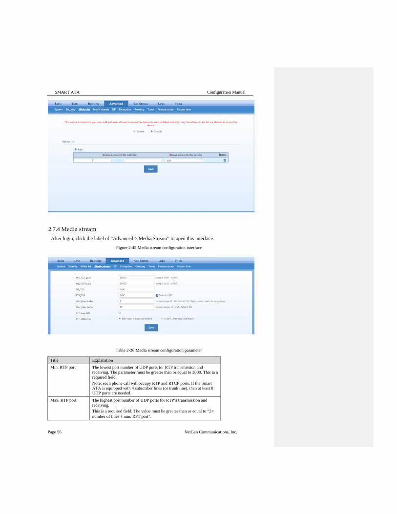
SMART ATA Configuration Manual
Page 56 NetGen Communications, Inc.
2.7.4 Media stream After login, click the label of “Advanced > Media Stream” to open this interface.
Figure 2-45 Media stream configuration interface
Table 2-26 Media stream configuration parameter
Title Explanation Min. RTP port The lowest port number of UDP ports for RTP transmission and
receiving. The parameter must be greater than or equal to 3000. This ia a required field. Note: each phone call will occupy RTP and RTCP ports. If the Smart ATA is equipped with 4 subscriber lines (or trunk line), then at least 8 UDP ports are needed.
Max. RTP port The highest port number of UDP ports for RTP’s transmission and receiving. This is a required field. The value must be greater than or equal to “2× number of lines+min. RPT port”.

Advanced Configuration
NetGen Communications, Inc. Page 57
Title Explanation TOS bits This parameter specifies the quality assurance of services with different
priorities. The default value is 0x0C. E.g.: TOS=0xB8 indicates level 5 that has no reliability requirement.
Min. Jitter buffer RTP Jitter Buffer is constructed to reduce the influence brought by network jitter. This default value is 3.
Max. Jitter buffer RTP Jitter Buffer helps to reduce the influence brought by network jitter. The default value is 50.
RTP drop SID Determine whether to discard received RTP SID voice packets. By default, SID voice packets will not be dropped. Note: RTP SID packets should be dropped only when they are in nonconformity to the specifications. Nonstandard RTP SID data could generate noise for calls.
RTP destination address
This parameter determines where to obtain the IP address of the receiving side for RTP packets. By default, the IP address is obtained “From SDP global connection”.
From SDP global connection: Obtain the IP address from SDP global connection;
From SDP media connection: Obtain the IP address from SDP Media Description.
2.7.5 SIP-related configuration SIP transactions, used to build a SIP dialog, consist of request and responses messages. Both may include a SIP message-header field and SIP message-body field. The SIP message header primarily describes the message sender and receiver; the SIP message body primarily describes the specific implementation method of the dialog.
Request: the SIP message sent by a client to the server for the purpose of activating the given operation, including INVITE, ACK, BYE, CANCEL, OPTION and UPDATE etc. Response: the SIP message sent by a server to the client as response to the request, including 1xx, 2xx, 3xx, 4xx, 5xx, and 6xx responses. Message header: A header is a component of a SIP message that conveys information in header fields about the message, such as Call-ID. Header fields have parameters, such as: Via, From, To, Contact, Csq, Content-length, Max-forward, Content-type, , and SDP etc. The Via header parameter generally is set to the NAT IP (external) address, not the LAN or internal IP address. Smart ATA provides flexibility in content setting in order to improve compatibility with the SIP register server. After login, click the label of “Advanced > SIP” to open this interface.
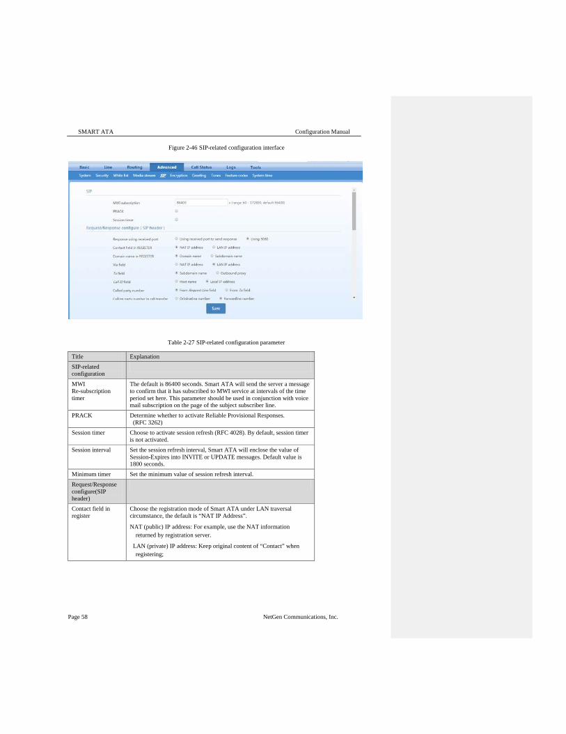
SMART ATA Configuration Manual
Page 58 NetGen Communications, Inc.
Figure 2-46 SIP-related configuration interface
Table 2-27 SIP-related configuration parameter
Title Explanation SIP-related configuration
MWI Re-subscription timer
The default is 86400 seconds. Smart ATA will send the server a message to confirm that it has subscribed to MWI service at intervals of the time period set here. This parameter should be used in conjunction with voice mail subscription on the page of the subject subscriber line.
PRACK Determine whether to activate Reliable Provisional Responses. (RFC 3262)
Session timer Choose to activate session refresh (RFC 4028). By default, session timer is not activated.
Session interval Set the session refresh interval, Smart ATA will enclose the value of Session-Expires into INVITE or UPDATE messages. Default value is 1800 seconds.
Minimum timer Set the minimum value of session refresh interval. Request/Response configure(SIP header)
Contact field in register
Choose the registration mode of Smart ATA under LAN traversal circumstance, the default is “NAT IP Address”.
NAT (public) IP address: For example, use the NAT information returned by registration server.
LAN (private) IP address: Keep original content of “Contact” when registering;

Advanced Configuration
NetGen Communications, Inc. Page 59
Title Explanation Domain name in register
The default is “Domain name”.
Domain name: Complete domain name used for registration (for example: [email protected]);
Sub domain name: Only use the common part of the name of domain (for example: [email protected]).
Via field Choose whether to use NAT (public) IP address or LAN (private) IP address for “Via” header field value, the default is “NAT IP address”. If your device is behind a GW/firewall that is SDP-aware (ALG), and inbound fax works but outbound does not work due to one-way media, try changing this setting.
To field Choose whether to apply Sub domain name or Outbound proxy to “To” header field, the default is “Sub domain name”.
Call ID field Choose whether to fill Call ID field with Host name or Local IP address, the default is “Local IP address”.
Called party number Choose whether Smart ATA acquires the called number from Request Line header field or To header field. The default is “From Request line field”.
Calling party number in call transfer
Under call forwarding, the calling party number sent can be chosen from Originating number or Forwarding number being set for sending, the default is “Forwarding number”. For example: the subscriber line 2551111 on Smart ATA activates call forwarding feature and set the destination to 3224422. When caller with 13055553333 calls 2551111, the call will be forwarded to 3224422:
if “Originating number” is chosen, the number 13055553333 will be sent to 3224422 as calling party number;
if “Forwarding number” is chosen, the number 2551111 will be sent to 3224422 as calling party number;
Do not validate Via Set whether to ignore Via field, By default, Via is ignored. Register upon invite timeout
Set whether to activate registration when SIP message of INVITE is failed or time expired, and by default, re-registration is not selected.
Selecting the receiving port for response
Use the receiving port of proxy or use the sending port of proxy.
2.7.6 Encryption After login, click the label of “Advanced > Encryption” to open this interface.
Comment [MBC1]: Not shown on the GUI image

SMART ATA Configuration Manual
Page 60 NetGen Communications, Inc.
Figure 2-47 Encryption configuration interface
Table 2-28 Encryption configuration parameters
Title Explanation Signal encrypt Choose whether to encrypt signaling. By default, this is disabled. Encryption method Set the Smart ATA encryption method, default is 7. The optional
parameters as below:
2:TCP not encrypted
3: TCP encrypted
6: UDP not encrypted
7: UDP not encrypted
8: Using keyword
10: RC4
13: Encrypt13
14: Encrypt14
16: Word reverse(263)
17: Word exchange(263)
18: Byte reverse(263)
19: Byte exchange(263)
20:VOS
Encryption key You may obtain it from service provider RTP encrypt Choose whether to encrypt RTP voice pack, the default is “0”
0: No encryption
1: Entire message
2: Header only
3: The data body only
T38 encryption Choose whether to encrypt T38 fax signaling. By default, this is disabled. Session Border Proxy

Advanced Configuration
NetGen Communications, Inc. Page 61
Title Explanation Server Set the IP address and port number of session border proxy server. The
character of “:” must be used between IP address and port number. Server address could be set into IP address or domain name. When domain name is used, “DNS service” must be activated as shown in the page of “configure network parameter”, and “DNS server” must be configured. Example: “201.30.170.38:5060” and “softswitch.com:5060”
Signaling port Signaling port assignment of the gateway, the default value is 4660. Signaling port number may be set at will, but can not conflict with other ports of equipment.
2.7.7 Greeting After login, click the label of “Advanced > Greeting” to open this interface. Greeting allows user change the voice prompts of Trunk(FXO) and color ring back tone of Line(FXS).
Figure 2-48 Greeting interface
2.7.8 Tones After login, click the label of “Advanced > Tones” to open this interface.
Figure 2-49 Call-progress tone configuration interface

SMART ATA Configuration Manual
Page 62 NetGen Communications, Inc.
Table 2-29 Call-Progress Tone configuration parameters
Title Explanation Country/Region There are progress tone plans for several countries and regions which are
pre-programmed in gateways. Users may also specify the tone plan according to the national standard. Smart ATA provide tone plans for the following countries and regions:
China; the United States; France; Italy; Germany; Mexico; Chile; Russia; Japan; South Korea; Hong Kong; Taiwan; India; Sudan; Iran; Algeria; Pakistan; Philippines; Kazakhstan;
Dial Prompt tone of off-hook dial tone 2nd dial Used for the second stage dial tone Message waiting Used for prompt of voice mail, or when the subscriber line is set with “Don’t
Disturb Service and Call Transfer”. Busy Used for busy line prompt Congestion Used for notification of call set up failure due to resource limit Ring back The tone sent to caller when ringing is on Disconnect/ Scatter Tone
Used for reminding the subscriber of off-hook and no dialup status of the phone
Call waiting Used for notification in call waiting Confirmation Used for confirming function keys being entered.
Here are examples that illustrate the various call-progress tones 350+440 (dial tone)
Indicates the dual–frequency tone consisting of 350 and 440 Hz 480+620/500,0/500 (busy)
Indicates the dual–frequency tone consisting of 480 and 620 Hz, repeated playing with 500 milliseconds on and 500 milliseconds off. Note: 0/500 indicates 500 milliseconds mute.
440/300,0/10000,440/300,0/10000 Indicates 440 Hz single frequency tone, repeated twice in terms of 300 milliseconds on and 10 seconds off.
950/333,1400/333,1800/333,0/1000 Indicates repeated playing 333 milliseconds of 950 Hz, 333 milliseconds of 1400 Hz, 333 milliseconds of 1800 Hz, and mute of 1 second
2.7.9 Service Feature Codes The feature codes consist of a system feature codes and service-specific feature codes. The system code (##) is used for acquiring Smart ATA information (e.g. IP address), and the latter is used for users to activate and inactivate supplementary services.
After login, click the label of “Advanced > Functional Keys” to open this interface.
The following are the examples of the dialing rule for the feature code: Using *xx (dial * and 2 digits number ) to activate a service; Using #xx (dial # and 2 digits number) to cancel a service.
This is illustrated with the following defaults for various parameters, which may be modified according to requirements.

Advanced Configuration
NetGen Communications, Inc. Page 63
Figure 2-50 Function-key configuration interface
Table 2-30 Functional keys configuration parameter
Title Explanation System feature codes
Query IP address The function key for determining the IP address of the ATA, with a default of ##. Dialing this key, users can hear Smart ATA voice the IP address and system-software version number. Narrative: if Smart ATA is only equipped with FXO (Line) port, connect FXO(Line) port through the PBX extension line or PSTN direct line, and dial the number of this line accordingly, press “##” immediately after hearing the second dial tone, users may thus hear the IP address and system software version number of the gateway.
Query phone number
The function key for determining the phone number of this subscriber line, with default of #00. By dialing this key, your will hear the phone number of the subscriber line voiced by the gateway.
Service feature codes
Activate CFU The function key for activating unconditional call forwarding, with a default of *60. Dialing this key will activate unconditional call forward of the line and set the destination number for call forwarding. User operation: Off hook → press *60 →enter the destination number. Users can determine the latest destination number set by dialing “ *60* ”. Note: it’s required to enable call forwarding service before using this function (please see the instructions on the relevant configuration of “subscriber line”).
Deactivate CFU The function key for deactivating unconditional call forwarding, with default of #60.
User operation: Off hook → press #60 → hang up.
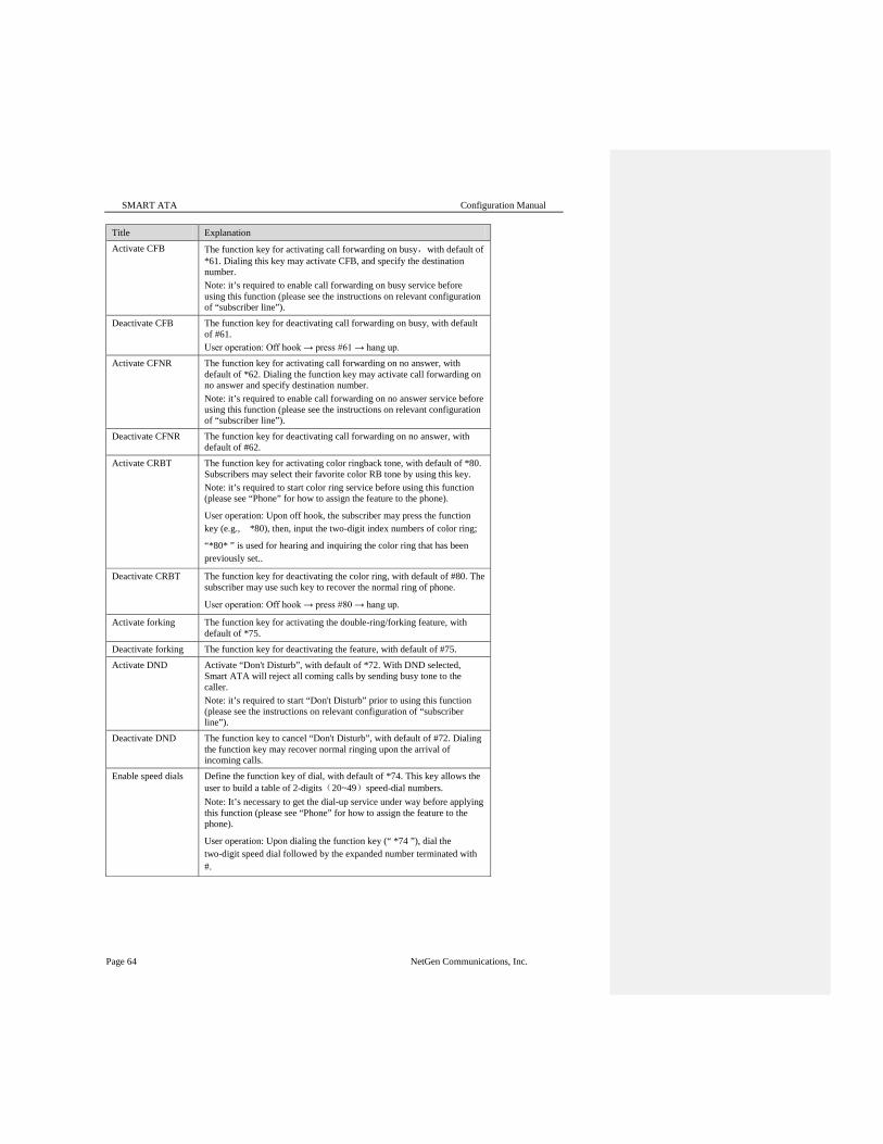
SMART ATA Configuration Manual
Page 64 NetGen Communications, Inc.
Title Explanation Activate CFB The function key for activating call forwarding on busy,with default of
*61. Dialing this key may activate CFB, and specify the destination number. Note: it’s required to enable call forwarding on busy service before using this function (please see the instructions on relevant configuration of “subscriber line”).
Deactivate CFB The function key for deactivating call forwarding on busy, with default of #61. User operation: Off hook → press #61 → hang up.
Activate CFNR The function key for activating call forwarding on no answer, with default of *62. Dialing the function key may activate call forwarding on no answer and specify destination number. Note: it’s required to enable call forwarding on no answer service before using this function (please see the instructions on relevant configuration of “subscriber line”).
Deactivate CFNR The function key for deactivating call forwarding on no answer, with default of #62.
Activate CRBT The function key for activating color ringback tone, with default of *80. Subscribers may select their favorite color RB tone by using this key. Note: it’s required to start color ring service before using this function (please see “Phone” for how to assign the feature to the phone).
User operation: Upon off hook, the subscriber may press the function key (e.g., *80), then, input the two-digit index numbers of color ring;
“*80* ” is used for hearing and inquiring the color ring that has been previously set..
Deactivate CRBT The function key for deactivating the color ring, with default of #80. The subscriber may use such key to recover the normal ring of phone.
User operation: Off hook → press #80 → hang up.
Activate forking The function key for activating the double-ring/forking feature, with default of *75.
Deactivate forking The function key for deactivating the feature, with default of #75. Activate DND Activate “Don't Disturb”, with default of *72. With DND selected,
Smart ATA will reject all coming calls by sending busy tone to the caller. Note: it’s required to start “Don't Disturb” prior to using this function (please see the instructions on relevant configuration of “subscriber line”).
Deactivate DND The function key to cancel “Don't Disturb”, with default of #72. Dialing the function key may recover normal ringing upon the arrival of incoming calls.
Enable speed dials Define the function key of dial, with default of *74. This key allows the user to build a table of 2-digits(20~49)speed-dial numbers. Note: It’s necessary to get the dial-up service under way before applying this function (please see “Phone” for how to assign the feature to the phone).
User operation: Upon dialing the function key (“ *74 ”), dial the two-digit speed dial followed by the expanded number terminated with #.
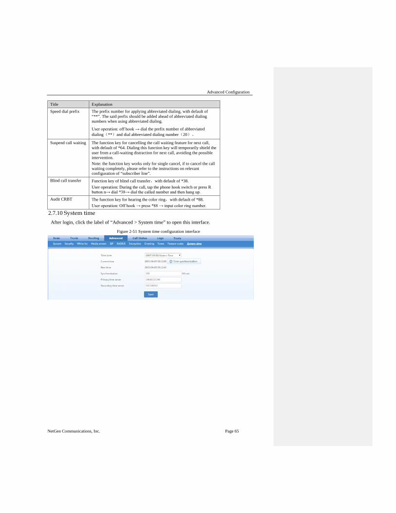
Advanced Configuration
NetGen Communications, Inc. Page 65
Title Explanation Speed dial prefix The prefix number for applying abbreviated dialing, with default of
“**”. The said prefix should be added ahead of abbreviated dialing numbers when using abbreviated dialing.
User operation: off hook → dial the prefix number of abbreviated dialing(**)and dial abbreviated dialing number(20)。
Suspend call waiting The function key for cancelling the call waiting feature for next call, with default of *64. Dialing this function key will temporarily shield the user from a call-waiting distraction for next call, avoiding the possible intervention. Note: the function key works only for single cancel, if to cancel the call waiting completely, please refer to the instructions on relevant configuration of “subscriber line”.
Blind call transfer Function key of blind call transfer,with default of *38. User operation: During the call, tap the phone hook switch or press R button n→ dial *38→ dial the called number and then hang up.
Audit CRBT The function key for hearing the color ring,with default of *88. User operation: Off hook → press *88 → input color ring number.
2.7.10 System time After login, click the label of “Advanced > System time” to open this interface.
Figure 2-51 System time configuration interface

SMART ATA Configuration Manual
Page 66 NetGen Communications, Inc.
Table 2-31 System time configuration parameters
Title Explanation Time Zone Select a time zone, and the parameter values include:
(GMT-11:00) Midway Island
(GMT-10:00) Honolulu. Hawaii
(GMT-09:00) Anchorage, Alaska
(GMT-08:00) Tijuana
(GMT-06:00) Denver
(GMT-06:00) Mexico City
(GMT-05:00) Indianapolis
(GMT-04:00) Glace Bay
(GMT-04:00) South Georgia
(GMT-03:30) Newfoundland
(GMT-03:00) Buenos Aires
(GMT-02:00) Cape Verde
(GMT) London (GMT+01:00) Amsterdam
(GMT+02:00) Cairo
(GMT+03:00) Moscow
(GMT+03:30) Teheran
(GMT+04:00) Muscat
(GMT+04:30) Kabul
(GMT+05:30) Calcutta
(GMT+05:00) Karachi
(GMT+06:00) Almaty
(GMT+07:00) Bangkok
(GMT+08:00) Beijing
(GMT+09:00) Tokyo
(GMT+10:00) Canberra
(GMT+10:00) Adelaide
(GMT+11:00) Magadan
(GMT+12:00) Auckland
Primary Server Enter the IP address of preferred time server here. This parameter must be set due to no default value.
Secondary Server
Enter the IP address of standby time server here. This parameter must be set due to no default value.

Status
NetGen Communications, Inc. Page 67
2.8 Status
2.8.1 Call status After login, click “Status > Call Status” to open this interface.
Figure 2-52 Interface of call status
Table 2-32 Parameters of call state
Title Explanation Line There are six types of line status, On-hook, Off-hook, Ringing,
Maintenance, Disconnect, Parallel line in-use. Call The call state includes Idle, Out-pusling, Ring, Entering number, In
progress, Ring back, Talk, Near end hung up, Far end hung up, and Timeout.
2.8.2 Call history on Phone After login, click the “Status > Call history on FXS” to open this interface.
Figure 2-53 Interface of call on FXS

SMART ATA Configuration Manual
Page 68 NetGen Communications, Inc.
2.8.3 Call history on Line After login, click the label of “Status > Call history on FXO” to open this interface.
Figure 2-54 Interface of call on FXO
2.8.4 SIP message count After login, click “Status > SIP message count” to open this interface.
Figure 2-55 Interface of SIP message count
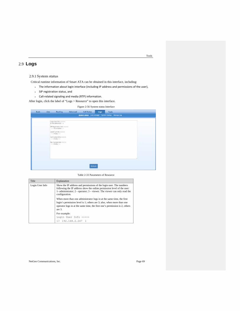
Tools
NetGen Communications, Inc. Page 69
2.9 Logs
2.9.1 System status Critical runtime information of Smart ATA can be obtained in this interface, including:
• The information about login interface (including IP address and permissions of the user),
• SIP registration status, and
• Call-related signaling and media (RTP) information. After login, click the label of “Logs > Resource” to open this interface.
Figure 2-56 System status Interface
Table 2-33 Parameters of Resource
Title Explanation Login User Info Show the IP address and permissions of the login user. The numbers
following the IP address show the online permission level of the user: 1- administrator; 2 - operator; 3 – viewer. The viewer can only read the configuration.
When more than one administrator logs in at the same time, the first login’s permission level is 1; others are 3; also, when more than one operator logs in at the same time, the first one’s permission is 2, others are 3. For example: Login User Info >>>>>
1) 192.168.2.247 1

SMART ATA Configuration Manual
Page 70 NetGen Communications, Inc.
Title Explanation SIP Registration Info
Show registration status:
Not enabled: The registration server’s address is not entered yet;
Latest response: The latest response message for the registration. 200 means registered successfully;
No response: No response from registration server. The cause may contribute to 1)incorrect address for the registration server; 2) IP network fault; or, 3) the registration server is not reachable.
For example: SIP Registration Info >>>>> ---- Not enabled ---- SIP Registration Info >>>>>
Contact: <sip:[email protected]:1003;user=phone>
latest response: 200 (timeout-555)
Contact: <sip:[email protected]:1003;user=phone>
latest response: 200 (timeout-555)
Latest Call Info Show the latest call. Call Context Info Show the call status. RTP Context Info
Show the voice channel related to the calls. For example: RTP Context Info >>>>>
3) created, call =e011
2.9.2 Call messages After login, click the label of “Logs > Call messages” to open this interface.
Figure 2-57 Call messages interface

Tools
NetGen Communications, Inc. Page 71
2.9.3 System startup After login, click the label of “Logs > System startup” to open this interface.
Figure 2-58 System startup interface
2.9.4 Log management After login, click “Logs > Log management” to open this interface. Log files can be downloaded through this interface.
Figure 2-59 Interface of Log management
Table 2-34 Configuration parameters of Log management
Title Explanation Log level Select the log file level of gateway, default is 4. The higher the level the
more details the log file will be. Note: log level should be set to 4 or lower when Smart ATA is used in normal operation, avoiding reducing the system performance.
System log server Set the IP address of the system log server. Local log port The port used to send logs. Log server IP address of debugging log server.
Procedure for downloading the log: Step 1: Click “Download”, Smart ATA begins to assemble the logs.

SMART ATA Configuration Manual
Page 72 NetGen Communications, Inc.
Step 2: After a few seconds, the interface of log saving will appear. Step 3: Click “Save”, and select path to save. Step 4: The user may review the log from the server.
2.10 Tools
2.10.1 Change password After login, click “Tools” to open this interface. Only administrator is entitled to change the password of login.
For changing administrator password, it’s required to enter new password into “New password” field and “Confirm new password” field, then click “Submit”.
The password being used by the operator will be displayed as hidden codes, which could be changed by the administrator at any time. The administrator is allowed to change the operator’s password by entering the new password into “Operator password > password”.
Figure 2-60 Interface for changing password
2.10.2 Configuration maintenance After login, click “Tools > Configuration maintenance” to open this interface. This feature allows user export and import configuration of Smart ATA.
2.10.3 Software upgrade After login, click “Tools > Software upgrade” to open this interface. The software upgrade procedure is presented as below:
Step 1: Obtain the upgrade files (tar.gz file), and save the file onto a local computer. Step 2: Click “Tools > Software upgrade” to access to the page of software upgrade. Step 3: Click “Browse” to select the upgrade files. Step 4: Click “Upload”,

Tools
NetGen Communications, Inc. Page 73
Step 5: Uploading will be completed in about 30 seconds, then click “Next”. Step 6: The following prompt appears during the upgrade.
A few minutes are needed to upgrade the gateway. Don’t operate the Smart ATA during this period.
Step 7: After success in upgrade, the following dialog will appear, click “Confirm”. Step 8: If Smart ATA is rebooting, the interface cannot be displayed. Step 9: Wait for about two minutes, and access the interface of the Smart ATA management system, click “Info” and check the software version.
2.10.4 Restore factory settings After login, click “Tools > Restore factory settings” to restore the factory settings.
The factory settings are designed based on common applications, and therefore, no need to modify them in many deployment situations. Also, users can choose reset network configuration/voice configuration/all configuration.
Figure 2-61 Interface of restore factory capture
2.10.5 TDM capture After login, click “Tools > TDM capture” to open this interface. This tool can be used to capture the voice stream from the Phone or Line interface. The capture starts from the off-hook if it is a Phone interface or from the ringing if it is a Line interface,and is ended on on-hook or call release. When the call lasts longer than 200 seconds, only the first 200 seconds of voice stream will be captured. The voice file is stored on the Smart ATA in PCMU format.
Figure 2-62 Interface of TDM capture
Steps:
1) Select the analog line ID to which you want to perform the capture.

SMART ATA Configuration Manual
Page 74 NetGen Communications, Inc.
2) Click Start to initiate the capture procedure.
3) Make the test call.
4) Click Stop to terminate the capture procedure. You will be notified for download.
2.10.6 Ethereal/Wireshark Capture After login, click “Tools > Ethereal capture” to open this interface. You are allowed to capture up to three IP voice data files, each with up to 2M bytes. The data files are stored on the Smart ATA in dump.cap format under catalog “/var/log”.
Figure 2-63 Interface of Ethereal capture
Steps:
1) Click Start to initiate the capture procedure.
2) Click Stop to terminate the capture procedure. You will be notified for download.
2.10.7 Network diagnosis After login, click “Tools > Network diagnosis” to open this interface. Automatic diagnosis helps you detect WAN connection. Diagnosis using Ping helps you check the connection between ATA and destination.
Figure 2-64 Interface of Network diagnosis

Appendix
NetGen Communications, Inc. Page 75
2.11 Version information
After login, click “Help” to view the Smart ATA hardware and software version information.
Figure 2-65 Interface of help
2.12 Logout
After login, click the “Logout” at top right to exit the Smart ATA management system and return to the login interface.

SMART ATA Configuration Manual
Page 76 NetGen Communications, Inc.
3 Appendix
3.1 Fix for SIP Devices Behind a NATed Device
3.1.1 Background Network Address Translation (NAT) allows a routing device to alter IP address in the IP header.
Figure 3-66 – A NAT Example
In Figure 3-662-41 – A NAT Example, a LAN-connected entity (“behind” the NAT) has an IP address of 192.168.16.22. The routing device is configured to perform NAT (it includes Domain Name Server (DNS)) and change the source IP address of outbound messages to 64.12.145.14, the routable/public IP address of the router/gateway. However, some higher-level (application-layer) protocols, such as Session Initiation Protocol (SIP) and Session Description Protocol (SDP) include IP address information in the body of the message. These IP addresses are usually unchanged by NAT, resulting in an inability of the correspondent (external) SIP entity to send information back to the NATed device since the device typically uses the IP address given to it by the DNS server, in this case 192.168.16.22.
LAN
192.168.16.22
Internet
Routerw/NAT
Smart ATA
64.12.145.14
Message with IP source =
192.168.16.22
Message with IP source =
64.12.145.14
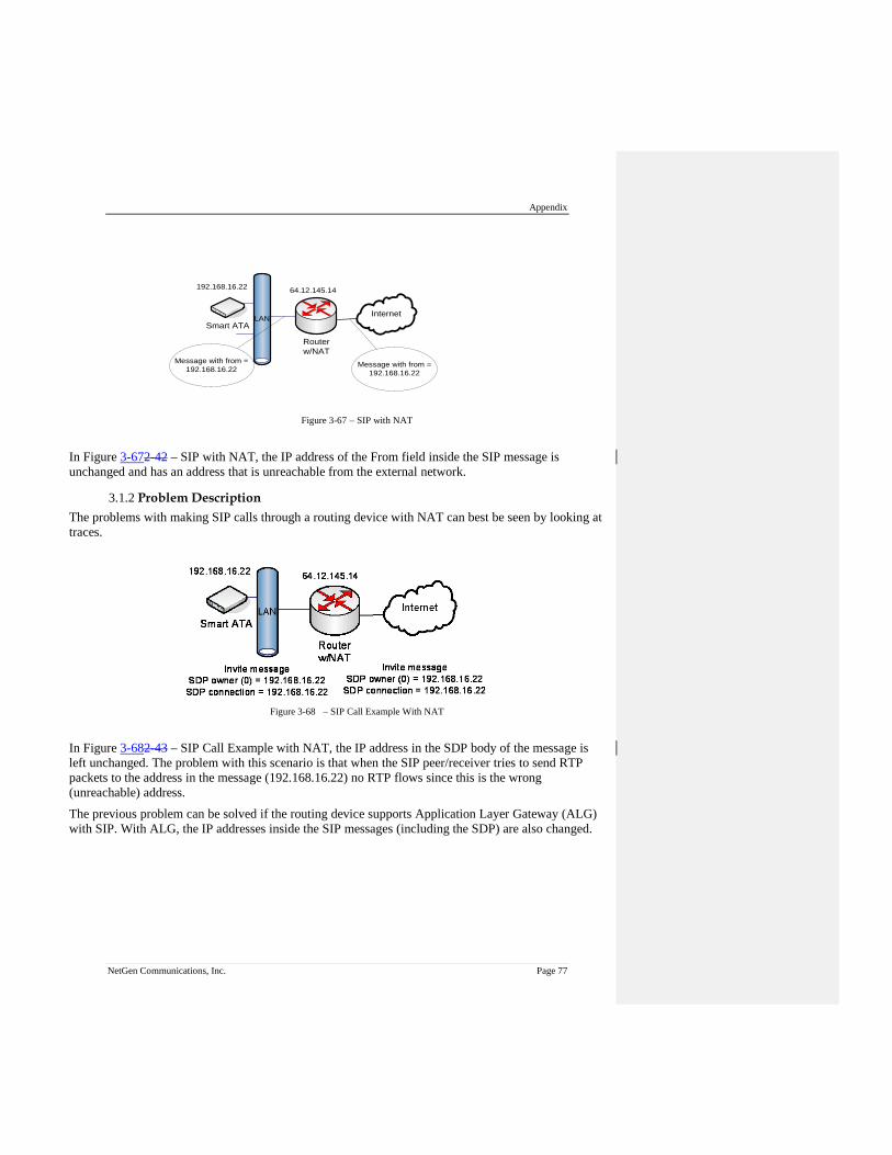
Appendix
NetGen Communications, Inc. Page 77
Figure 3-67 – SIP with NAT
In Figure 3-672-42 – SIP with NAT, the IP address of the From field inside the SIP message is unchanged and has an address that is unreachable from the external network.
3.1.2 Problem Description The problems with making SIP calls through a routing device with NAT can best be seen by looking at traces.
Figure 3-68 – SIP Call Example With NAT In Figure 3-682-43 – SIP Call Example with NAT, the IP address in the SDP body of the message is left unchanged. The problem with this scenario is that when the SIP peer/receiver tries to send RTP packets to the address in the message (192.168.16.22) no RTP flows since this is the wrong (unreachable) address. The previous problem can be solved if the routing device supports Application Layer Gateway (ALG) with SIP. With ALG, the IP addresses inside the SIP messages (including the SDP) are also changed.
LAN
192.168.16.22
Internet
Routerw/NAT
Smart ATA
64.12.145.14
Message with from = 192.168.16.22
Message with from = 192.168.16.22

SMART ATA Configuration Manual
Page 78 NetGen Communications, Inc.
Figure 3-69 – SIP Call Example With NAT and ALG
Figure 3-692-44 – SIP Call Example with NAT and ALG shows how the routing device correctly changes the IP address in the SDP, allowing the receiver to send the SDP packets to the correct address. The routing device will then forward the packets to the 192.168.16.22 device. This scenario works for G.711 pass-through fax calls since the ALG function is setup to handle VoIP. However, FoIP with T.38 is another story. For T.38 calls, the routing device does not correctly alter the messages related to Re-Invites to T.38.
Figure 3-70 – SIP Call Example (T.38)
In Figure 3-702-45 – SIP Call Example (T.38), everything is correct until the 200 OK response from 192.168.16.22 to the T.38 Re-Invite. The routing device is not T.38 aware, so it incorrectly alters the SDP body of the message.
3.1.3 Solution The solution to the problem of making SIP-based FoIP calls with T.38 support from behind a NAT routing device is to turn off ALG and configure Smart ATA with the IP address that the network should use to communicate with it. (The Smart ATA User Manual calls this the “NAT IP Address.”) Then, the correspondent SIP UA client can fill in the SIP message and SDP body with that IP address. This is shown in Figure 3-712.46 – SIP Example With Fix.
LAN
192.168.16.22
Internet
Routerw/NAT & ALG
Smart ATA
64.12.145.14
Invite messageSDP owner (0) = 192.168.16.22SDP connection = 192.168.16.22
Invite messageSDP owner (0) = 64.12.145.14SDP connection = 64.12.145.14
Invite message (T.38 re-Invite)
200 OKSDP owner (0) = 192.168.16.22SDP connection = 192.168.16.22
Invite message (T.38 re-Invite)
200 OKSDP owner (0) = garbageSDP connection = garbage

Appendix
NetGen Communications, Inc. Page 79
Figure 3-71 – SIP Example With Fix
3.1.4 Implementation If it’s on a LAN, by default the ATA obtains its IP address via DHCP and fills it in on the Network configuration page. (You can override the default on that page by using the drop-down to select Static or PPPoE.) You should not need to know the NAT IP (public) Address since it is obtained by the ATA during the DHCP exchange. To correctly configure the ATA for operation behind a NAT device, go to Advanced>>System and make sure Dynamic NAT is selected at the top of the screen and NAT IP Address radio button is selected, rather than the Local IP Address. Now go to Advanced>>SIP, and make sure that NAT IP Address is selected for “Contact field in register” and “Via field.”
LAN
192.168.16.22
Internet
Routerw/NAT (ALG Disabled)
Smart ATA
64.12.145.14
Invite messageSDP owner (0) = 64.12.145.14SDP connection = 64.12.145.14
Invite messageSDP owner (0) = 64.12.145.14SDP connection = 64.12.145.14
Invite message (T.38 re-Invite)
200 OKSDP owner (0) = 64.12.145.14SDP connection = 64.12.145.14
Invite message (T.38 re-Invite)
200 OKSDP owner (0) = 64.12.145.14SDP connection = 64.12.145.14
SMART ATA Configuration Manual
Page 80 NetGen Communications, Inc.
3.2 Using Smart ATA with Commetrex’ BladeWare
Many organizations that are adding fax servers are reluctant to invest in PSTN-specific systems, electing to acquire FoIP servers based on BladeWare, even though they are not quite ready to move to an all-IP system. For these applications where the port requirements are low (2-8 ports), Smart ATA can be used as an affordable interim PSTN interface since it is available in a configuration with two office trunks, making it an IP-PSTN gateway. This means that IP traffic can be routed to and from the FXO/office trunks. Configure the routing rules as follows:
1. On the ATA's web interface, go to routing>>routing table. 2. Click on help at the bottom of the page. 3. Read the intro, then go to #9, Routing calls to PSTN. 4. Click “return” at the bottom of the page. 5. Enter the following:
IP X ROUTE FXO 1-2/R This causes calls from the IP network/BladeWare to be routed to line ports 1 and 2 in round-robin order
6. For the reverse direction: FXO[1-2] X ROUTE IP <ip_address_or_domain_name>:<port_num> This causes FXO calls to be routed to BladeWare at the specified address.
7. Click the Submit button. Section 2.4.2 of the Smart ATA manual gives additional information.