HVL/ccTM Medium Voltage, Metal-Enclosed … Medium Voltage, Metal-Enclosed Switchgear 2.4 to 38 kV,...
56
Instruction Bulletin Retain for future use. HVL/ccTM Medium Voltage, Metal-Enclosed Switchgear 2.4 to 38 kV, 60 to 150 kV BIL 25 Short-time, Indoor or Outdoor Class 6045 SQI ARE D www . ElectricalPartManuals . com
Transcript of HVL/ccTM Medium Voltage, Metal-Enclosed … Medium Voltage, Metal-Enclosed Switchgear 2.4 to 38 kV,...

Instruction Bulletin Retain for future use.
HVL/ccTM Medium Voltage, Metal-Enclosed Switchgear 2.4 to 38 kV, 60 to 150 kV BIL 25 kA Short-time, Indoor or Outdoor Class 6045
SQI....JARE D
www . El
ectric
alPar
tMan
uals
. com

HAZARD CATEGORIES AND SPECIAL SYMBOLS
PLEASE NOTE
[I]� A
Read these instructions carefully and look at the equipment to become familiar with the device before trying to instal l , operate, service or maintain it. The following special messages may appear throughout this bulletin or on the equipment to warn of potential hazards or to call attention to information that clarifies or simplifies a procedure.
The addition of either symbol to a "Danger" or "Warning" safety label indicates that an electrical hazard exists which will result in personal injury if the instructions are not followed .
This is the safety alert symbol. It is used to alert you to potential personal injury hazards. Obey all safety messages that follow this symbol to avoid possible injury or death.
A WARNING WARNING ind icates a potentially hazardous situation which, if not avoided, can result in death or serious injury .
.A CAU TION CAUTION indicates a potentially hazardous situation which, i f not avoided, can result in minor or moderate injury.
CAU TION CAUTION, used without the safety alert symbol, indicates a potentially hazardous situation which, if not avoided, can result in property damage.
NOTE: Provides additional information to clarify or simplify a procedure.
Electrical equipment should be installed, operated, serviced, and maintained only by qualified personnel. No responsibil ity is assumed by Schneider Electric for any consequences arising out of the use of this materia l .
www . El
ectric
alPar
tMan
uals
. com

6045-1 02/2004
TABLE OF CONTENTS SECTION 1 : INTRODUCTION
SECTION 2: SAFETY PRECAUTIONS
SECTION 3: RECEIVING, HANDLING, AND STORAGE
SECTION 4: INSTALLATION
© 1999-2004 Schneider Electric All Rights Reserved
HVUcc Metal-Enclosed Switchgear Table of Contents
Before You Begin . . . . . . . . . . . . . . . . . . . . . . . . . . . . . . . . . . . . . . . . . . . . . . . . . . . . . . . . . . . . . . . . . . . . . . . . . . . . . . . . . . . . . . . . . 7 General Description . . . . . . . . . . . . . . . . . . . . . . . . . . . . . . . . . . . . . . . . . . . . . . . . . . . . . . . . . . . . . . . . . . . . . . . . . . . . . . . .. . . . . 7 Enclosures . . . . . . . . . . . . . . . . . . . . . . . . . . . . . . . . . . . . . . . .. . . . . . . . . . . . . . . . . . . . . . . . . . . . . . . . . . . . . . . . . . . . . . . . . . . . . . . . . . . 8 Compartments . . . . . . . . . . . . . . . . . . . . . . . . . . . . . . . . . . . . . . . . . . . . . . . . . . . . . . . . . . . . . . . . . . . . . . . . . . . . . . . . . . . . . . . . . . . 10
Bus-Bar Compartment .. . . . . . . . . . . . . . . . . . . . . . . . . . . . . . . . . . . . . . . . . . . . . . . . . . . . . . . . . . . . . . . . . . . . . . . . 10 Upper Panel/Low Voltage Compartment . . . . . . . . . .. . . . . . . . . . . . . . . . . . . . . . . . . . . . . . . . . . . . 10 Fuse/Load-side Compartment . . . . . . . . . . . . . . . . . . . . . . . . . . . . . . . . . . . . . . . . . . . . . . . . . . . . . . . ... . . . . 11 Mechanism Compartment . . . . . . . . . . . . . . . . . . . . . . . . . . . . . . . . . . . . . . . . . . . . . . . . . . . . . . . . . . . . . . . . . . . . 11
Mechanisms . . . . . . . . . . . . . . . . . . . . . . . . . . . . . . . . . .. . . . . . . . . . . . . . . . . . . . . . . . . . . . . . . . . . . . . . . . . . . . . . . . . . . . . . . . . . . . . 12 Over-toggle Mechanism (OTM) . . . . . . . . . . . . . . . . . . . . . . . . . . . . . . . . . . . . . . . . . . . . . . . . . . . . . . . . . . . . 12 Stored Energy Mechanism (SEM) . . . . . . . . . . . . . . . . . . . . . . . . . . . . . . . . . . . . . . . . . . . . . . . . . . . . . . . . 13
Interrupter Switch . . . . . . .. . . . . . . . . . . . . . . . . . . . . . . . . . . . . . . . . . . . . . . . . . . . . . . . . . . . . . . . . . . . . . . . . . . . . . .. . . . . . . . . 14 Optional Grounding Switch . . . . . . . . . . .. . . . . . . . . . . . . . . . . . . . . . . . . . . . . . . . . . . . . . . . . . . . . . . . . . . . . . . 14
Load-side Access Panel . . . . . . . . . . . . . . . . . . . . . . . . . . . . . . . . . . . . . . . . . . . . . . . . . . . . . . . . . . . . . . . . . . . . . . . . . . . . 15 Cable Termination . . . . . . . . .. . . . . . . . . . . . . . . . . . . . . . . . . . . . . . . . . . . . . . . . . . . . . . . . . . . . . . . . . . . . . . . . . . .. . . . . . ... 15 Fuselogic™ System Components . . . . . . . . . . . . . . . . . . . . . . . . . . . . . . . . . . . . . . . . . . . . . . . . . . . . . . . . . . . . . 15 Blown Fuse Indicator (BFI) . . . . . . . . . . . . . . . . . . . . . . . . . . . . . . . . . . . . . . . . . . . . . . . . . . . . . . . . . . . . . . . . . . . . . . . . 15 Live-Line Indicators (LLI)/ Capacitive Divider (CD) . . . . . . . . . . . . . . . . . . . . . . . . . . . . . . . . . . . . 15 Load-side Discharge Assembly (LOA) . . . . . . . . . . . . . . . . . . . . . .. .. . . . . . . . . . . . . . . . . . . . . . . . . . . . . . . 16 Panel Interlocks . . . . . . . . . . . . . . . . . . . . . . . . . . . . . . . . . . . . . . . . . . . . . . . . . . . . . . . . . . . . . . . . . . . . . . . . . . . . . . . . . . . . . . . . . 17 Class 1, Division 2 Certification . . . . .. . . . . . . . . . . . . . . . . . . . . . . . . . . . . . . . . . . . . . . . . . . . . . . . . . . . . . . . . . . . 17
· · · · · · · · · · · · · · · · · · · · · · · · · · · · · · · · · · ·· · · · · · · · · · · · · · · · · · · · · · · · · · · · · · · · · · · · · · · · · · · · · · · · · · · · · · · · · · · · · · · · · · · · · · · · · · · · · · · · · 18
Receiving . . . . . . . . . . . . . . . . . . . .. . . . . . . . . . . . . . . . . . . . . . . . . . . . . . . . . . . . . . . . . . . . . . . . . . . . . . . . . . . . . . . . . . . . . . . . .. . . . . . 19 Identification . . . . . . . . . . . . . . . . . . . . . . . . . . . . . . . .. . . . . . . . . . . . . . . . . . . . . . . . . . . . . . . .. . . . . . . . . . . . . . . . . . . . . . . . . 19
Handling . . . . .. . . . . . . . . . . . . . . . . . . . . . . . . . . . . . . . . . . . . . . . . . . . . . . . . . . . . . . . . . . . . . . . . . . . . . . . . . .. . . . . . . . . . . . . . . . . . . . . 20 Lifting Provision-Indoor . . . . . . . . . . . . . . . . . . . . . . . . . . . . . . . . . . . . . . . . . . . . . . . . . . . . . . . . . . . . . . . . . . . . . . . . 20 Lifting Provision-Outdoor . . . . . . . . . . . . . . . . . . . . . . . . . . . . . . . . . . . . . . .. . . . . . . .. . . . . . . . . . . . . . . . . . . . . . 21 Using a Forklift . . . . . . . . . . . . . . . . . . . . . . . . . . . . . . . . . . . . . . . . . . . . . . . . . . . . . . . . . . . . . . . . . . . . . . . . . . . . . . . . . . . . . 22
Storage . . . . . . . . . . . . . . . . . . . . . .. . . . . . . . . . . . . . . . . . . . .. . . . . . .. . . . . . . . . . . . . . . . . . . . . . . . . . . . . . . . . . . . . . . . . . . . . . . . . . . . 22 2.4-15 kV Switchgear Indoor (NEMA 1 Construction) . . . . . . . . . . . . . . . . . . . . . . . . . 23 2.4-15 kV Switchgear Outdoor (NEMA 3R Construction) . . . . . . . . . . . . . . . . . . . . 24 25.8-38 kV Switchgear Indoor (NEMA 1 Construction) . . . . . . . . . . . . . . . . . . . . . . . 25 25.8-38 kV Switchgear Outdoor (NEMA 3R Construction) . . . . . .. . . . . . . . . . . . 26
Site Preparation . . . . . . . . . . . . . . . . . . . . . . . . . . . . . . . . . . . . . . . . . . . . . . . . . . . . . . . . . . . . . . . . . . . . . . . . . . . . . . . . . . . . . . . . . 27 Operating the Switches . . . . . . . . . . . . . . . . . . . . . . . . . . . . . . . . . . . . . . . . . . . . . . . . . . . . . . . . . . . . . . . . . . . . . . . . . . . . . . 28
Operating the Ground Switch (if equipped) . . . . . . . . . . . . . . . . . . . . . . . . . . . . . . . . . . . . . .. . . . 28 Operating Switchgear Equipped With an OTM . . . . . . . . . . . . . . . . . . . . . . . . . . . . . . . . . . . . 29 Operating Switchgear Equipped With an SEM . . . . . . . . . . . . . . . . . . . . . . . . . . . . . . . . . . . . 30
Access Panel Removal . . . . . . .. . . . .. . . . .... . . . . .. . . . .. . . . ... . . . . . . . . . . . . . . . . . . . . . . . . . . . . . . . . . . . . . . . . . 31 Removing the Load-side Access Panels . .. . . . . .. . . . .. . . . . .. . . . . . . . . . . . . . . . . . . . . . . . . . . 31
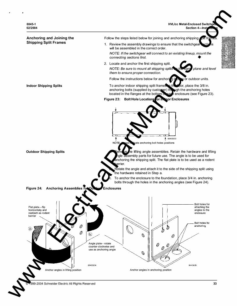
Field Assembly . . . . . . . . . . . . . . . . . . . . . . . . . . . . . . . . . . . . . . . . . . . . . . . . . . . . . . . . . . . . . . . . . . . . . . . . . . . . . . . . . . . . . . . . . . 32 Anchoring and Joining the Shipping Split Frames . . . . . . . . . . . . . . . . . . . . . . . . . . . . . . . 33
Indoor Shipping Spl its . . . . . . . . . . ... . . . . . . . . . . . . . . . . . . . . . . . . . . . . . . . . . . . . . . . . . . . . . . . . . . .. . . . . 33 Outdoor Shipping Splits . . . . . . .. . . . . . . . . . . . . . . . . . . . . . . . . . . . . . . . . . . . . . . . . . . . . . . . . . . . . . . . . . . 33
Bus Connections . . . . . . . . . . . .. . . . . . . . . . . . . . . . . . . . . . . . . . . . . . . . . . . . . . . . . . . . . . . . . . . . . . . . . . . . . . . . . . . . . . 35 Control Wiring Connections . . . . . . . . . . . . . . . . . . . . . . . . . . . . . . . . . . . . . . . . . . . . . . . . . . . . . . . . . . . . . . . . . 36
Cable Connections . . . . . . . . . . . . . . . . . . . . . . . . . . . . . . . . . . . . . . . . . . .. . . . . . . . . . . . . . . . . . . . . . . . . . . . . . . . . . . . . . . . . 37 Forming the Cables . . . . . . . . . . . . . . . . . . . . . . . . . . . . . . . . . . . . . . . . . . . . . . . . . . . . . . . . . . . . . . . . . . . . . . .. . . . . . . 37 Shielded Cables Through Window-Type Current Transformers . . . . . . . . . . 37 Unshielded Cable Connections . . . . . . . . . . . . . . . . . . . . . . . . . . . . . . . . . . . . . . . . . . . .. . . . . . . . .. . . . . . . 38
Fuse Replacement . . . . . . . . . . . .. . . . . . . . . . . . . . . . . . . . . . . . . . . . . . .. . . . . . . . . . . . . . . . . . . . . . . . . . . . . . . . . . . . . . . . . . 39 Fuse Removal . . . . . . . . . . . . . . . . . . . . . . . . . . . . . . . . . . . . . . . . . . . . . . . . . . . . . . . . . . . . . . . . . . . . . . . . . . . . . . . . . . . . . . 39 Fuse Installation . . . . . . . . . . . . . . . . . . . . . . . . . . . . . . . . . . . . . . . . . . . . . . . . . . . . . . . . . . . . . . . . . . . . . . . . . . . . . . . . . . . 40
3
www . El
ectric
alPar
tMan
uals
. com
HVL/cc Metal-Enclosed Switchgear
Table of Contents
SECTION 5:
SECTION 6:
4
FINAL PREPARATION AND
ENERGIZA TION
INSPECTION, MAINTENANCE,
AND TROUBLESHOOTING
6045-1
02/2004
Hi-pot (Dielectric) Testing . . . . . . . . . . . . . . . . . . . . . . . . . . . . . . . . . . . . . . . . . . . . . . . . . . . . . . . . . . . . . . . . . . . . . . . . . . . 41 Final Inspection . . . . . . . . . . . . . . . . . . . . . . . . . . . . . . . . . . . . . . . . . . . . . . . . . . . . . . . . . . . . . . . . . . . . . . . . . . . . . . . . . . . . . . . . . . 42
Final Operating Checks . . . . . . . . . . . . . . . . . . . . . . . . . . . . . . . . . . . . . . . . . . . . . . . . . . . . . . . . . . . . . . . . . . . . . . . . . . . . . . 43 Energization . . . . . . . . . . . . . . . . . . . . . . . . . . . . . . . . . . . . . . . . . . . . . . . . . . . . . . . . . . . . . . . . . . . . . . . . . . . . . . . . . . . . . . . . . . . . . . . 43
Inspection/Preventative Maintenance Guidelines . . . . . . . . . . . . . . . . . . . . . . . . . . . . . . . . . . . . . . 45 Inspection . . . . . . . . . . . . . . . . . . . . . . . . . . . . . . . . . . . . . . . . . . . . . . . . . . . . . . . . . . . . . . . . . . . . . . . . . . . . . . . . . . . . . . . . . . . . . 45
Recommended Inspection Interval . . . . . . . . . . . . . . . . . . . . . . . . . . . . . . . . . . . . . . . . . . . . . . . . . 45 Inspection Procedure . . . . . . . . . . . . . . . . . . . . . . . . . . . . . . . . . . . . . . . . . . . . . . . . . . . . . . . . . . . . . . . . . . . . . . 45
Preventive Maintenance . . . . . . . . . . . . . . . . . . . . . . . . . . . . . . . . . . . . . . . . . . . . . . . . . . . . . . . . . . . . . . . . . . . . . . . 46 Maintenance Log . . . . . . . . . . . . . . . . . . . . . . . . . . . . . . . . . . . . . . . . . . . . . . . . . . . . . . . . . . . . . . . . . . . . . . . . . . . . 46 Preventative Maintenance Intervals . . . . . . . . . . . . . . . . . . . . . . . . . . . . . . . . . . . . . . . . . . . . . . . . 46 Environmental Conditions . . . . . . . . . . . . . . . . . . . . . . . . . . . . . . . . . . . . . . . . . . . . . . . . . . . . . . . . . . . . . . . 47
Replacement Parts . . . . . . . . . . . . . . . . . . . . . . . . . . . . . . . . . . . . . . . . . . . . . . . . . . . . . . . . . . . . . . . . . . . . . . . . . . . . . . . . . . . . . 49 Corrective Maintenance . . . . . . . . . . . . . . . . . . . . . . . . . . . . . . . . . . . . . . . . . . . . . . . . . . . . . . . . . . . . . . . . . . . . . . . . . . . . . 51
Medium Voltage Fuses . . . . . . . . . . . . . . . . . . . . . . . . . . . . . . . . . . . . . . . . . . . . . . . . . . . . . . . . . . . . . . . . . . . . . . . . . 51 Live Line Indicator (LLI) Replacement . . . . . . . . . . . . . . . . . . . . . . . . . . . . . . . . . . . . . . . . . . . . . . . . . . 52
Class 1 , Division 2 Maintenance Requirements . . . . . . . . . . . . . . . . . . . . . . . . . . . . . . . . . . . . . . . . . 53 Troubleshooting . . . . . . . . . . . . . . . . . . . . . . . . . . . . . . . . . . . . . . . . . . . . . . . . . . . . . . . . . . . . . . . . . . . . . . . . . . . . . . . . . . . . . . . . . 54
© 1999-2004 Schneider Electric All Rights Reserved
www . El
ectric
alPar
tMan
uals
. com

6045-1 02/2004
LIST OF FIGURES
© 1999-2004 Schneider Electric All Rights Reserved
Figure 1 : Figure 2: Figure 3 : Figure 4: Figure 5: Figure 6: Figure 7: Figure 8: Figure 9: Figure 1 0: Figure 1 1: Figure 12 : Figure 13 : Figure 1 4: Figure 1 5: Figure 1 6: Figure 1 7: Figure 1 8: Figure 1 9: Figure 20: Figure 21: Figure 22: Figure 23 : Figure 24: Figure 25: Figure 26: Figure 27: Figure 28: Figure 29: Figure 30: Figure 3 1: Figure 32:
Figure 33: Figure 34: Figure 35: Figure 36: Figure 37: Figure 38: Figure 39:
HVL/cc Metal-Enclosed Switchgear List of Figures
Indoor Switchgear (NEMA 1 construction) . . . . . . . . . . . . . . . . . . . . . . . . . . . . . 8 Outdoor Switchgear (NEMA 3 R construction) . . . . . . . . . . . . . . . . . . . . . . . 9 Switch Cubicle . . . . . . . . . . . . . . . . . . . . . . . . . . . . . . . . . . . . . . . . . . . . . . . . . . . . . . . . . . . . . . . . . . . . . 1 0 Mechanism Covers . . . . . . . . . . . . . . . . . . . . . . . . . . . . . . . . . . . . . . . . . . . . . . . . . . . . . . . . . . . . . . 1 1 Over-Toggle Mechanism (OTM) . . . . . . . . . . . . . . . . . . . . . . . . . . . . . . . . . . . . . . . . . . 1 2 Stored Energy Mechanism (SEM) . . . . . . . . . . . . . . . . . . . . . . . . . . . . . . . . . . . . . . . 1 3 Cross-section of the Interrupter Switch/Disconnector . . . . . . . . . 14 Contact Blade Positions . . . . . . . . . . . . . . . . . . . . . . . . . . . . . . . . . . . . . . . . . . . . . . . . . . . . . . 1 4 Load-side Discharge Assembly Location . . . . . . . . . . . . . . . . . . . . . . . . . . . . 1 6 Panel Interlock Provisions . . . . . . . . . . . . . . . . . . . . . . . . . . . . . . . . . . . . . . . . . . . . . . . . . . . 1 7 Lifting Provision-Indoor . . . . . . . . . . . . . . . . . . . . . . . . . . . . . . . . . . . . . . . . . . . . . . . . . . . . . . . 20 Lifting Provision-Outdoor . . . . . . . . . . . . . . . . . . . . . . . . . . . . . . . . . . . . . . . . . . . . . . . . . . . . 2 1 Handling Using a Forklift . . . . . . . . . . . . . . . . . . . . . . . . . . . . . . . . . . . . . . . . . . . . . . . . . . . . . 22 Side, Front, and Plan Drawings-Indoor (Application A) . . . . 23 Side and Plan Drawing-Outdoor (Application A) . . . . . . . . . . . . . . . 24 Side, Front, and Plan Drawings-Indoor (Application A) . . . . 25 Side and Plan Drawing-Outdoor (Application A) . . . . . . . . . . . . . . . 26 Operating the Ground Switch (if equipped) . . . . . . . . . . . . . . . . . . . . . . . . . 28 Switchgear Operation (OTM) . . . . . . . . . . . . . . . . . . . . . . . . . . . . . . . . . . . . . . . . . . . . . . 29 Switchgear Operation (SEM) . . . . . . . . . . . . . . . . . . . . . . . . . . . . . . . . . . . . . . . . . . . . . . . 30 Removing the Load-side Access Panel-Application A . . . . . . 3 1 Removing the Load-side Access Panel-Application B . . . . . . 32 Bolt Hole Locations for Indoor Enclosures . . . . . . . . . . . . . . . . . . . . . . . . . . 33 Anchoring Assemblies for Outdoor Enclosures . . . . . . . . . . . . . . . . . . . 33 Joining the Shipping Splits and Installing the End Panels . . . 34 Anchoring Subsequent Indoor Shipping Splits . . . . . . . . . . . . . . . . .. . . 34 Anchoring Subsequent Outdoor Shipping Sections . . . . . . . . . . . . 35 Bus Bar Connections . . . . . . . . . . . . . . . . . . . . . . . . . . . . . . . . . . . . . . . . . . . . . . . . . . . . . . . . . . . 35 Example of a Typical Cable Connection . . . . . . . . . . . . . . . . . . . . . . . . . . . . . 37 Example of Unshielded Cable Support . . . . . . . . . . . . . . . . . . . . . . . . . . . . . . . 38 Fuse Removal (Application A shown) . . . . . . . . . . . . . . . . . . . . . . . . . . . . . . . . . 39 Fuse Characteristics and Striker Pin Directions (Application A position shown) . . . . . . . . . . . . . . . . . . . . . . . . . . . . . . . . . . . . . . . . . . . . 40 Fuse Installation (Application A shown) . . . . . . . . . . . . . . . . . . . . . . . . . . . . . . 40 Using Live Line Indicators . . . . . . . . . . . . . . . . . . . . . . . . . . . . . . . . . . . . . . . . . . . . . . . . . . . 43 Phase Sequence Testing . .. . . . . . . . . . . . . . . . . . . . . . . . . . . . . . . . . . . . . . . . . . . . . . . . . . 44 Typical Life of HVUcc (a) 25.8 and 38 kV, (b) 5 and 1 5 kV 48 Typical Schematic . . . . . . . . . . . . . . . . . . . . . . . . . . . . . . . . . . . . . . . . . . . . . . . . . . . . . . . . . . . . . . . 50 LLI Tag (located on the wiring harness) . . . . . . . . . . . . . . . . . . . . . . . . . . . . . . 52 Class 1 , Division 2 Required Features . . . . . . . . . . . . . . . . . . . . . . . . . . . . . . . . 53
5
www . El
ectric
alPar
tMan
uals
. com

HVL/cc Metal-Enclosed Switchgear
List of Tables
LIST OF TABLES
6
Table 1 : Table 2: Table 3 : Table 4: Table 5: Table 6: Table 7: Table 8: Table 9: Table 1 0: Table 1 1:
6045-1
02/2004
Approximate Dimensions and Weights 2.4- 1 5 kV- Indoor . . . 23 Approximate Dimensions and Weights 2.4-1 5 kV-Outdoor 24 Approximate Dimensions and Weights 25.8-38 kV-Indoor . 25 Approximate Dimensions and Weights 25.8-38 kV-Outdoor26 Torque Values . . . . . . . . . . . . . . . . . . . . . . . . . . . . . . . . . . . . . . . . . . . . . . . . . . . . . . . . . . . . . . . . . . . . 36 Hi-Pot Test Values ... . . . . . . . . . . . . . . . . . . . . . . . . . . . . . . . . . . . . . . . . . . . . . . .. . .. . . . . . . . . . 41 Recommended Maintenance Guidelines . . . . . . . . . . . . . . . . . . . . . . . . . . . . . 46 Replacement Parts . . . . . . . . . . . . . . . . . . . . . . . . . . . . . . . . . . . . . . . . . . . . . . . . . . . . . . . . . . . . . . 49 Troubleshooting General Issues . . . . . . . . . . . . . . . . . . . . . . . . . . . . . . .. . . .. . . . . . . 54 Troubleshooting Mechanism Issues . . . . . . . . . . . . . . . . . . . . . . . . . . . . . . . . . . . . 54 Maintenance Log . . . . . . . . . . . . . . .. . . . . . . . . . . . . . . . . . . . . . . . . . . . . . . . . . . . . . . . . . . .. .. . . . 55
© 1999-2004 Schneider Electric All Rights Reserved
www . El
ectric
alPar
tMan
uals
. com
6045-1 02/2004
HVL/cc Metal-Enclosed Switchgear Section 1-lntroduction
SECTION 1-INTRODUCTION
BEFORE YOU BEGIN
GENERAL DESCRIPTION
© 1999-2004 Schneider Electric All Rights Reserved
This bulletin contains instructions for the proper installation, operation, and maintenance of HVL/cc™ Metal-Enclosed Switchgear manufactured by Schneider Electric. This product offers switching, metering, and interrupting capabilities for medium voltage systems ranging from 2 .4 kV to 38 kV, 60 kV BIL to 1 50 kV BIL. The equipment is available in a variety of arrangements and in enclosures designed and constructed for indoor (NEMA 1 ) and outdoor (NEMA 3 R) use.
Read and understand:
- this bulletin before performing the installation, operation, and maintenance steps described in this bulletin.
- the HVUcc Grounding Switch Application section of the Metal Enclosed Load Interrupter Switchgear with HVUcc Switches catalog (document number 6045CT9801 ).
NOTE: If more information on the grounding switch application for this equipment is needed, contact your Schneider Electric representative.
Electrical equipment should be installed and serviced only by qualified electrical personnel in accordance with national and local electrical codes.
HVL/cc switchgear is made up of modular units containing fixed mounted interrupters with or without replaceable E-rated fuses. It is a compact design with front accessibil ity. Equipment may be furnished in single or multiple bay units. Sections are shipped assembled for ease of handling and installation. HVL/cc metal-enclosed switchgear from Schneider Electric is designed, manufactured, and tested in accordance with ANSI standards C37.20.3, C37.20.4, C37.57, C37.58, Canadian standards CSA 22.2 no. 3 1 , CSA 22.2 no. 1 93 , and NEMA SG5 where applicable.
7 www . El
ectric
alPar
tMan
uals
. com
HVL/cc Metal-Enclosed Switchgear Section 1-lntroduction
ENCLOSURES
8
6045-1
02/2004
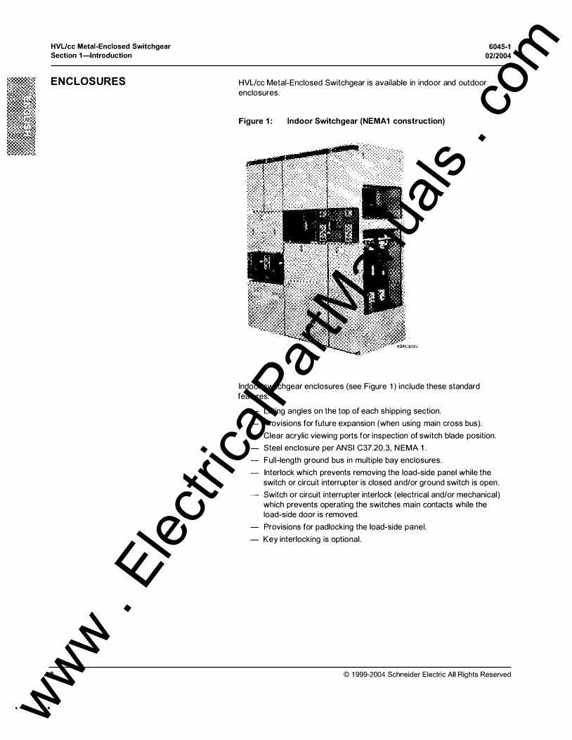
HVL!cc Metal-Enclosed Switchgear is available in indoor and outdoor enclosures.
Figure 1 : Indoor Switchgear (NEMA1 construction)
Indoor switchgear enclosures (see Figure 1) include these standard features:
Lifting angles on the top of each shipping section.
Provisions for future expansion (when using main cross bus).
Clear acrylic viewing ports for inspection of switch blade position.
Steel enclosure per ANSI C37.20.3 , N EMA 1 .
Full-length ground bus in multiple bay enclosures.
Interlock which prevents removing the load-side panel while the switch or circuit interrupter is closed and/or ground switch is open .
Switch or circuit interrupter interlock (electrical and/or mechanical) which prevents operating the switches main contacts while the load-side door is removed.
Provisions for padlocking the load-side panel.
Key interlocking is optional.
© 1999-2004 Schneider Electric All Rights Reserved
www . El
ectric
alPar
tMan
uals
. com
6045-1 02/2004
© 1999-2004 Schneider Electric All Rights Reserved
HVUcc Metal-Enclosed Switchgear Section 1-lntroduction
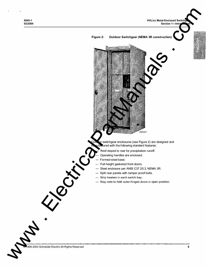
Figure 2: Outdoor Switchgear (NEMA 3R construction)
Outdoor switchgear enclosures (see Figure 2) are designed and manufactured with the following standard features:
Roof sloped to rear for precipitation runoff.
Operating handles are enclosed.
Formed steel base.
Full-height gasketed front doors.
Steel enclosure per ANSI C37.20.3, NEMA 3 R.
- Split rear panels with tamper proof bolts.
- Strip heaters in each switch bay.
- Stay rods to hold outer-hinged doors in open position.
9
www . El
ectric
alPar
tMan
uals
. com

HVUcc Metal-Enclosed Switchgear
Section 1-lntroduction
COMPARTMENTS
Figure 3: Switch Cubicle
6045-1
02/2004
The information contained in this section describes the compartments of HVL!cc Switchgear (see Figure 3).
,-, 1 ' 0/
@ I• I ·1 _.::<:;�-::29 �J:4J I @ (� @ @> (�.\IIIJl • 1:1 ®
J) !D
i§: I �, I l'lt' �"lf�_'p/ I
Application A (Load side-Bottom) Application B (Load side-Top)
1. Bus bar compartment 2. Upper panel or LV compartment 3. Mechanism compartment
Bus-Bar Compartment
4. Interrupter switch or disconnector 5. Fuse or Load-side compartment 6. Load-side access Panel
7. Cable Termination 8. Capacitive Divider 9. Live Line Indicators (Llls)
10. Bolted Front Panel {App. B only) 11 . Viewing Ports 12. Rating nameplate
The bus-bar compartment is completely isolated from the other compartments of the equipment by the epoxy body of the interrupter or 1 1 gauge steel barriers. The bus bars extend continuously through the length of the switchgear and may transition from appl ication A to application B bus compartments and vice versa. Two main bus positions allow future extensions and connections to existing equipment.
HVL/cc bus has been tested to 25 kA for two seconds with 68 kA peak (40 kA momentary) current levels. It has been further tested to the full-integrated level of 63 kA using a four-frame run of bus, including a 29.5 in . (750 mm) compartment. The bus bar is 1 /4 in.x 2 in. (6 x 51 mm) tin-plated copper for 600 A or two 1 /4 in.x 2 in . (6 x 51 mm) for 1 200 A.
Upper Panel/Low Voltage Compartment The Upper Panel/Low Voltage Compartment has a bolted panel when there are no controls or relays present in this vertical section. When any of these devices are present the low-voltage compartment will have a hinged panel.
1 0
The Low Voltage Compartment houses terminal blocks and supports relay or monitoring device that may be supplied with the switchgear l ine-up . All auxiliary contacts for the control of the mechanism are wired to terminal blocks for customer access and are located in this compartment. Provision for an optional thermal scanning window can be provided in this panel.
© 1999-2004 Schneider Electric All Rights Reserved
www . El
ectric
alPar
tMan
uals
. com
6045-1 02/2004
Fuse/Load-side Compartment
Mechanism Compartment
© 1999-2004 Schneider Electric All Rights Reserved
HVL/cc Metal-Enclosed Switchgear Section 1-lntroduction
The Fuse/Load-side compartment houses fuses, voltage transformers (VT), the control power transformer (CPT), or bus connections. The panel is interlocked with the switch and can be padlocked by several methods (see Figure 10 on page 17).
The HVL/cc can be equipped with either an over toggle mechanism (OTM) or a stored energy mechanism (SEM).
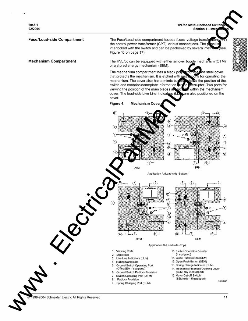
The mechanism compartment has a black polycarbonate and steel cover that protects the mechanism. It is etched with instructions for operating the mechanism. The cover also has a mimic bus that shows the position of the switch and contains nameplate information for the interrupter. Two ports for viewing the position of the main blades are located within the mechanism cover. The load-side Live Line Indicators (LLis) are also positioned on the cover.
Figure 4: Mechanism Covers
Application A (Load-side-Bottom)
OTM SEM
Application B (Load side-Top)
1. Viewing Ports 2. Mimic Bus 3. Live Line Indicators (Llls) 4. Rating Nameplate 5. Ground Switch Operating Port
(OTM/SEM if equipped) 6. Ground Switch Padlock Provision 7. Switch Operating Port (OTM)
10. Switch Operation Counter (if equipped)
11. Close Push Button (SEM) 12. Open Push Button (SEM) 13. Spring Charge Indicator (SEM) 14. Mechanical Interlock Opening Lever
(SEM only if equipped) 15. Motor Cut-off Switch
(SEM only-if equipped) 8. Padlock Provision 60453004 9. Spring Charging Port (SEM)
1 1 www . El
ectric
alPar
tMan
uals
. com
HVL/cc Metal-Enclosed Switchgear
Section 1-lntroduction 6045-1
0212004
MECHANISMS The mechanism compartment cover comes with optional padlock provisions for blocking access to the control functions of the interrupter. The covers do not prevent electrical operation of either the mechanism or the Fuselogic™ function from tripping the interrupter.
Optional electrical mechanical, and/or keyed interlocks can be supplied to block the switch operations outlined in this bulletin.
The HVL/cc Switchgear Mechanism Compartment contains the operators for both the main switch and the grounding switch . Available mechanisms are listed below:
Manually operated Over Toggle Mechanism (Type OTM)
Motor operated Over Toggle Mechanism (Type OTM)
Manually operated Stored Energy Mechanism (Type SEM) with optional Fuselogic system
Motor operated Stored Energy Mechanism (Type SEM) with open and close coils, and optional Fuselogic system
NOTE: Only manually operated OTM and SEM available in Class 1, Division 2 applications.
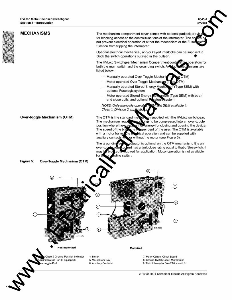
Over-toggle Mechanism (OTM) The OTM is the standard mechanism supplied with the HVL/cc switchgear. The mechanism requires the springs to be compressed into an over-toggle position where they release their energy for closing and opening the device. The speed of the blades is independent of the user. The OTM is available with a motor for remote electrical operation and can be supplied with auxiliary contacts with or without the motor (see Figure 5).
Figure 5:
1 2
The grounding switch actuator is optional on the OTM mechanism. I t is an over-toggle actuator and has a fault close rating equal to that of the switch . It may be blocked if required for application . Motor operation is not available for the grounding switch.
Over-Toggle Mechanism (OTM)
Non-motorized
1. Open/Close & Ground Position Indicator 4. Motor 2. Ground Switch Port (if equipped) 5. Motor Gear Box 3. Over-toggle Port 6. Auxiliary Contacts
Motorized
7. Motor Control Circuit Board 8. Ground Switch Cutoff Microswitch 9. Main Interrupter Cutoff Microswitch
© 1999-2004 Schneider Electric All Rights Reserved
www . El
ectric
alPar
tMan
uals
. com
6045-1 02/2004
HVL/cc Metal-Enclosed Switchgear Section 1-lntroduction
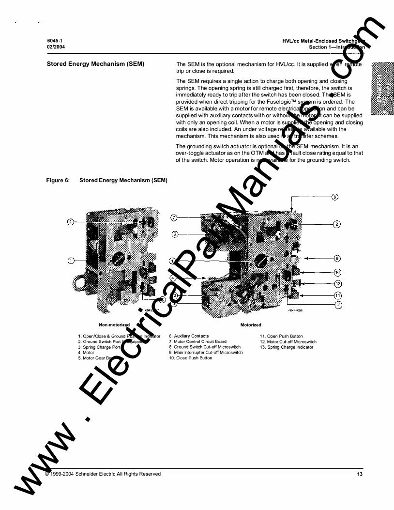
Stored Energy Mechanism (SEM) The SEM is the optional mechanism for HVUcc. It is supplied when remote trip or close is required.
Figure 6: Stored Energy Mechanism (SEM)
Non-motorized
The SEM requires a single action to charge both opening and closing springs. The opening spring is still charged first, therefore, the switch is immediately ready to trip after the switch has been closed. The SEM is provided when direct tripping for the Fuselogic™ system is ordered . The SEM is available with a motor for remote electrical operation and can be supplied with auxiliary contacts with or without the motor. It can be supplied with only an opening coi l . When a motor is supplied the opening and closing coils are also included. An under voltage release is available with the mechanism. This mechanism is also used in all transfer schemes.
The grounding switch actuator is optional on the SEM mechanism. It is an over-toggle actuator as on the OTM and has a fault close rating equal to that of the switch . Motor operation is not available for the grounding switch.
Motorized
1. Open/Close & Ground Position Indicator 6. Auxiliary Contacts 11. Open Push Button 2. Ground Switch Port (if equipped) 7. Motor Control Circuit Board
3. Spring Charge Port 8. Ground Switch Cut-off Microswitch 4. Motor 9. Main Interrupter Cut-off Microswitch 5. Motor Gear Box 1 0. Close Push Button
12. Motor Cut-off Microswitch 13. Spring Charge Indicator
© 1 999-2004 Schneider Electric All Rights Reserved 13 www . El
ectric
alPar
tMan
uals
. com

HVL/cc Metal-Enclosed Switchgear
Section 1-lntroduction
INTERRUPTER SWITCH
Optional Grounding Switch
14
6045-1
02/2004
The interrupter housing is an epoxy enclosure that is sealed for life and contains SF6 gas at 5.8 psi gauge for up to 1 7.5 kV switchgear and 22 psi gauge for 25.8-38 kV switchgear. The SF6 gas is used to help extinguish the electrical arc. This low-pressure enclosure protects the main contacts from the environment. It completely contains al l interruption by-products, including the arc, allowing this interrupter to be used in environments where air switches are not suitable.
NOTE: L 1, L2, and L31abeling on the switch housing is not representative of phase sequence A, B, C.
Figure 7: Cross-section of the Interrupter SwitchiDisconnector
1. Switch Epoxy Housing 3. Switch Blades 2. Fixed Contact 4. Operating Shaft
The three rotating blades are sealed in the enclosure and have only one external rotating seal. Figure 8 shows the three positions of the rotating blades.
Figure 8: Contact Blade Positions
Open Closed Grounded 60453010
The distance between the fixed and moving contacts is sufficient to withstand the normal recovery voltage and system-imposed transient recovery voltages (TRVs). The distance is great enough to also withstand 1 1 0% of the rated BIL and 60 cycle withstand voltages.
The interrupter switch has an optional feature which enables the switch to be grounded . For more information on units with grounding switches refer to the HVUcc Grounding Switch Application section of the Metal Enclosed Load Interrupter Switchgear with HVUcc Switches catalog (document number 6045CT9801 ) or call your local Schneider Electric representative.
© 1999-2004 Schneider Electric All Rights Reserved
www . El
ectric
alPar
tMan
uals
. com
6045-1 02/2004
LOAD-SIDE ACCESS PANEL
CABLE TERMINATION
FUSELOGIC™ SYSTEM COMPONENTS
BLOWN FUSE INDICATOR (BFI)
LIVE-LINE INDICATORS (LLI)/ CAPACITIVE DIVIDER (CD)
© 1999-2004 Schneider Electric All Rights Reserved
HVUcc Metal-Enclosed Switchgear Section 1-lntroduction
The load-side access panel is mechanically interlocked with the switch. It is provided with locating and latching hooks and a "tee" slot for the switch interlock (see Figure 1 0 on page 1 7). When the optional load-side discharge assembly (LOA) is supplied, a view port is also provided for identifying the position of the LOA. Provision for an optional thermal scanning window can also be provided in this panel.
Lugs are provided for HVL/cc. DO NOT USE OTHER MANUFACTURERS LUGS for the medium voltage cable unless authorized by Schneider Electric. The lugs are mounted inside the field shapers and will accommodate one or two cables.
The Fuselogic system prevents inadvertent switching until fuses have been installed or blown ones replaced. The system is provided as an option on HVL/cc Metal-Enclosed Switchgear. It is available with the SEM mechanism only.
The Fuselogic system uses Square D medium voltage fuses with special blown fuse indicator pin. This blown fuse indicator works in conjunction with the switch to form a simple lockout mechanism. The Fuselogic™ system functions without auxiliary power in most cases.
The optional BFI is available with either the OTM or SEM mechanisms. The assembly is located on the line side of the fuse. It operates a flag that can be seen through a hole in the mechanism cover. The BFI drives a direct acting trip or a time delayed trip when supplied with Fuselogic system schemes.
The Llls are equipped with neon lamps that indicate the presence of voltage. They are visible on the front of the mechanism cover. They are wired to the CD located on the load side of the switch. Optional COs are installed on the main bus or l ine side of the switch with the LLI mounted on the front panel.
Test ports on the Llls are suitable for testing voltage with a properly rated voltage sensing device (see Figure 34 on page 43). Llls are not a replacement for voltage indication when accessing a switch compartment. Use properly rated test equipment to ensure no voltage is present before performing any maintenance procedures.
The CD is a standoff support insulator with the capacitor permanently bonded inside. The power from this capacitor provides the energy required for the neon lamps of the Llls. The energy can also be used to activate optional features such as an auto-transfer scheme.
15 www . El
ectric
alPar
tMan
uals
. com
HVUcc Metal-Enclosed Switchgear
Section 1-lntroduction
LOAD-SIDE DISCHARGE ASSEMBLY (LOA)
1 6
6045-1
02/2004
The LOA is a device used to discharge to ground any residual voltage on the load side of the fuses after the grounding switch has closed. The device operates in conjunction with the grounding switch and is available only on fused units equipped with an optional grounding switch.
Figure 9: Load-side Discharge Assembly Location
0 0
r 000+-
Load-side Discharge Assembly l
1 """ 7? �
� """ :;:: �
·n 'II�
llli .rlh �
�� ��
�� ��
1-
� 0
0 0 I
Front View Side view (enclosure)
For more information on units with grounding switches refer to the "HVL/cc Grounding Switch Application" section of the "Metal Enclosed Load Interrupter Switchgear with HVL/cc Switches" catalog (document number 6045CT9801) or call your local Schneider Electric representative.
A WARNING HAZARD OF ELECTRIC SHOCK, BURN, OR EXPLOSION
Use the load-side discharge assembly (LOA) only where there is no possibil ity of load-side back-feed from alternate power sources such as commercial power, down stream generator, and/or charged capacitor bank.
Failure to follow this instruction can result in death or serious injury.
NOTE: The LOA does not have fault making capabilities.
© 1999-2004 Schneider E lectric All Rights Reserved
www . El
ectric
alPar
tMan
uals
. com

6045-1 02/2004
PANEL INTERLOCKS
CLASS 1, DIVISION 2 CERTIFICATION
© 1 999-2004 Schneider Electric All Rights Reserved
HVUcc Metal-Enclosed Switchgear Section 1-lntroduction
The HVUcc is equipped with mechanical interlocks as a standard feature to minimize hazards to the user. The switch interlock prevents removing the load-side panel while the load interrupter switch is closed (also open and ungrounded if so equipped). Padlock provisions are also available for the load-side panel.
Additional padlocking provisions are available for both or either the motor cut-off switch and/or the ground switch. The load switch can be padlocked by using an optional padlocking provision located on the polycarbonate hinge covers of the mechanism cover.
Key interlocks are optional equipment. They are often supplied in conjunction with metal-enclosed switchgear to d irect proper operation and coordination of the equipment. The key interlock schemes are usually described on the switchgear assembly drawings supplied with the equipment.
Figure 1 0: Panel Interlock Provisions
Additional padlock provisions """"'-.... �
Hole for padlock
Tab must fit in slot
The Class 1 , Division 2 switchgear is used in hazardous areas. It is certified by Factory Mutual Research Corporation for T3B locations with heaters and T5 locations without heaters. The Class 1 , Division 2 switchgear is maintained in the same manner as the standard switchgear with the exceptions noted throughout this bulletin. Special features of Class 1 , Division 2 rated equipment are:
Explosion proof T3B rated heaters
- Uses only non-indicating fuses (see Figure 32 on page 40)
Uses only manually operated switch mechanisms (OTM or SEM)
- Test ports on the LLI heads are factory plugged.
17 www . El
ectric
alPar
tMan
uals
. com
HVUcc Metal-Enclosed Switchgear
Section 2-Safety Precautions 6045-1
02/2004
SECTION 2- SAFETY PRECAUTIONS
18
Carefully read and follow to the safety precautions outlined below before attempting to lift, move, instal l , use, or maintain HVL/cc Metal-Enclosed Switchgear and its components.
A DANG ER HAZARD O F ELECTRIC SHOCK, BURN, OR EXPLOSION.
• Only qual ified electrical personnel familiar with medium voltage circuits are to perform work described in this set of i nstructions. Workers must understand the hazards involved in working with or near medium voltage equipment.
• Qualified electrical personnel must perform work in accordance with national and local electric codes.
• Perform such work only after reading and understanding al l of the instructions contained in this bulletin.
• Turn off all power supplying this equipment before working on or inside. • Always use a properly rated voltage sensing device to confirm that power
is off. • Beware of potential hazards, wear personal protective equipment and
take adequate safety precautions. • Before performing visual inspections, tests, or maintenance on the
equipment, disconnect all sources of electric power. Assume that all circuits are live until they have been completely de-energized, tested, grounded, and tagged . Pay particular attention to the design of the power system. Consider all sources of power, including the possibil ity of backfeed ing.
• Before making any electrical connection, ensure that all leads to be connected are de-energized with proper safety grounds applied .
• Metal-enclosed switchgear have interlocks designed to minimize hazards to the user. It is not possible to eliminate every hazard with interlocks. The user of this device is responsible for recognizing the potential hazards, for wearing protective safety equipment, and for taking adequate safety precautions.
• Do not make any adjustments to the equipment or operate the system with safety features removed. Contact your local Schneider Electric representative for additional instructions if the device does not function as described in this manual.
• Handle this equipment carefully and instal l , operate and maintain it correctly in order for it to function properly. Neglecting fundamental installation and maintenance requirements may lead to personal injury, as well as damage to electrical equipment or other property.
• Careful ly inspect your work area and remove any tools and objects left inside the equipment.
• Replace all devices, doors, and covers before turning on the power to this equipment.
• All instructions in this manual are written with the assumption that the customer has taken these measures before performing maintenance or testing.
Failure to follow these instructions wil l result in death or serious injury.
© 1999-2004 Schneider Electric Al l Rights Reserved
www . El
ectric
alPar
tMan
uals
. com
6045-1 02/2004
HVUcc Metal-Enclosed Switchgear Section 3-Receiving, Handling, and Storage
SECTION 3- RECEIVING, HANDLING, AND STORAGE
RECEIVING
Identification
© 1 999-2004 Schneider Electric All Rights Reserved
This chapter contains information regarding the receiving, handling, and storage of HVL!cc Metal-Enclosed Switchgear.
Metal-enclosed switchgear is shipped on skids with protective wrapping to prevent damage during normal transit. Check the packing list against the equipment received to ensure the order and shipments are complete. Claims for shortages or other errors must be made in writing to Schneider Electric within 30 days after receipt of shipment. Failure to do so constitutes unqualified acceptance and a waiver of all such claims by the purchaser.
Upon receipt, immediately inspect the switchgear for damage that may have occurred during transit. If damage is found or suspected, immediately file a claim with the carrier and notify Schneider Electric.
The rating nameplate is located on the front cover of the operating mechanism. Included on the nameplate is the following information:
1. Factory order number
2. Manufacture date
3. Rated maximum voltage
4 . Impulse B IL (kV)
5 . Power frequency withstand (kV)
6 . Frequency
7 . Switch continuous current (amperes)
8. Main bus ratings
9 . Momentary current (kA)
10. Short time current (kA)
11 . Fault closing current (kA)
1 2. Fuse information
NOTE: All ratings are the MAXIMUM limits of the equipment.
19 www . El
ectric
alPar
tMan
uals
. com
HVL/cc Metal-Enclosed Switchgear
Section 3-Receiving, Handling, and Storage
HANDLING
Lifting Provision-Indoor
20
6045-1 02/2004
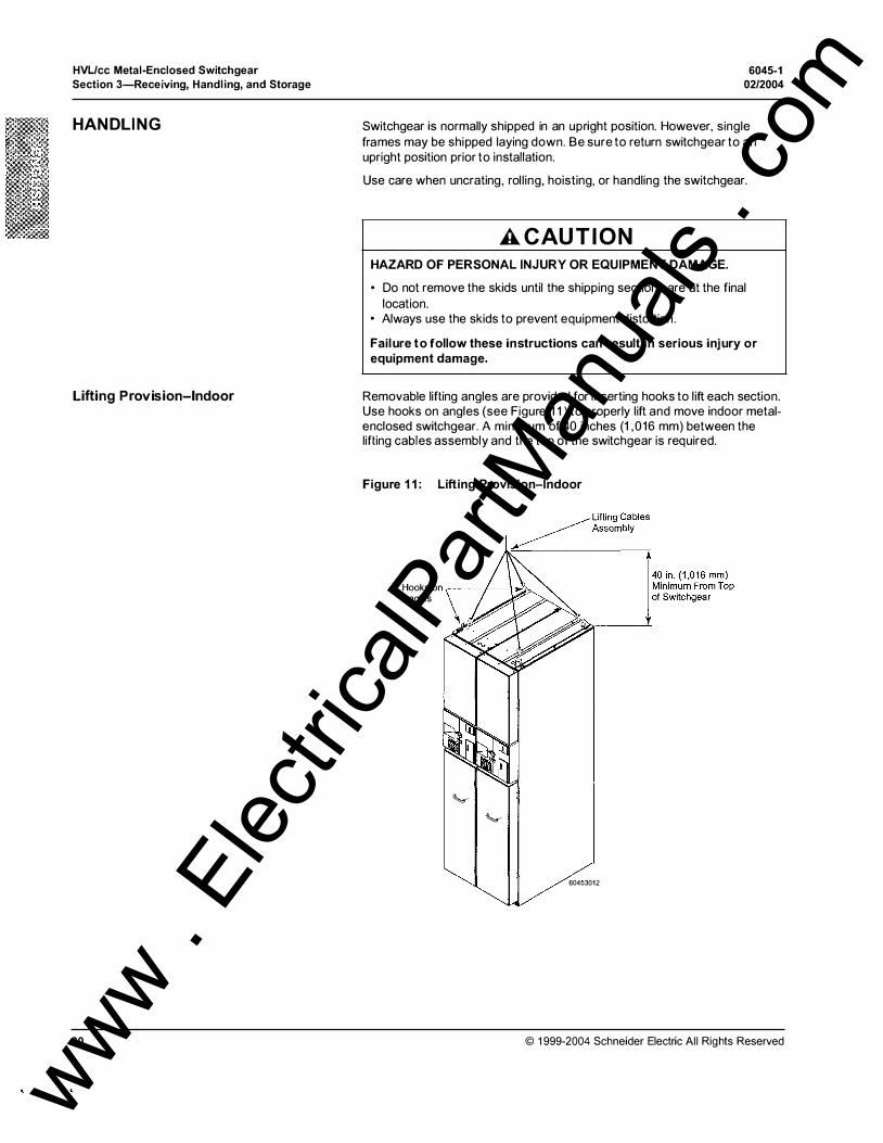
Switchgear is normally shipped in an upright position. However, single frames may be shipped laying down. Be sure to return switchgear to an upright position prior to installation.
Use care when uncrating, rol l ing, hoisting, or handling the switchgear.
A CAU TION HAZARD OF PERSONAL INJURY OR EQUIPMENT DAMAGE.
• Do not remove the skids until the shipping sections are at the final location.
• Always use the skids to prevent equipment distortion .
Failure to follow these instructions can result in serious injury or equipment damage.
Removable lifting angles are provided for inserting hooks to lift each section. Use hooks on angles (see Figure 1 1 ) to properly lift and move indoor metalenclosed switchgear. A minimum of 40 inches (1 ,016 mm) between the lifting cables assembly and the top of the switchgear is required.
Figure 1 1 : Lifting Provision-Indoor
Hooks on , I '• �� Angles
� �
60453012
© 1 999-2004 Schneider Electric Al l Rights Reserved
www . El
ectric
alPar
tMan
uals
. com

6045-1 02/2004
Lifting Provision-Outdoor
© 1999-2004 Schneider Electric All Rights Reserved
HVUcc Metal-Enclosed Switchgear Section 3-Receiving, Handling, and Storage
Lifting angles are provided for inserting hooks to l ift each shipping section. Retain these angles and hardware for use in anchoring outdoor shipping sections (see "Anchoring and Join ing the Shipping Split Frames" on page 33 and Figure 24 on page 33). A minimum of 40 inches (1 ,016 mm) between the lifting cables assembly and the top of the switchgear is required. Use spreader bars and hook to the bottom provisions (see Figure 12) to properly l ift and move outdoor metal-enclosed switchgear.
Figure 12: Lifting Provision-Outdoor
� Lifting Cables � Assembly
Spreader Bars are Required on Outdoor Metal-Enclosed Switchgear
Hooks on Bottom Provisions
I <0 lo. {1 ,0'6 mm) Minimum From Top of Switchgear
60453013
21 www . El
ectric
alPar
tMan
uals
. com
HVUcc Metal-Enclosed Switchgear
Section 3-Receiving, Handling, and Storage
Using a Forkl ift
STORAGE
22
6045-1 02/2004
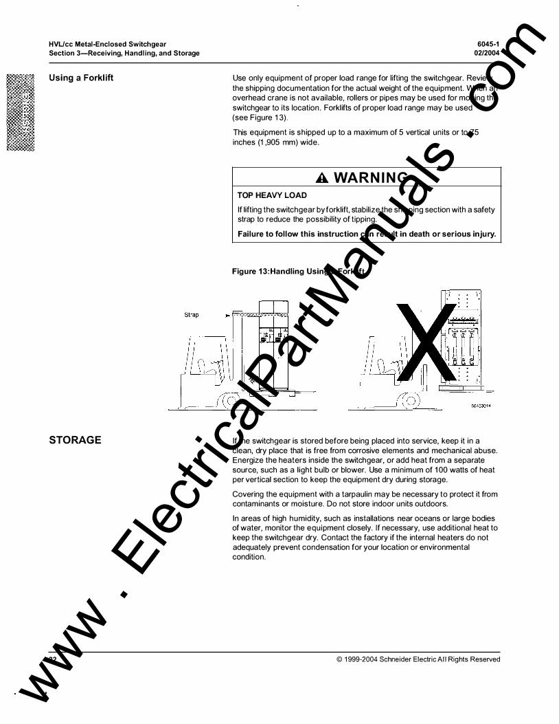
Use only equipment of proper load range for lifting the switchgear. Review the shipping documentation for the actual weight of the equipment. When an overhead crane is not available, rollers or pipes may be used for moving the switchgear to its location . Forklifts of proper load range may be used (see Figure 13).
This equipment is shipped up to a maximum of 5 vertical units or to 75 inches (1 ,905 mm) wide.
A WARNING TOP HEAVY LOAD
If lifting the switchgear by forklift, stabilize the shipping section with a safety strap to reduce the possibility of tipping.
Failure to fol low this instruction can result in death or serious injury.
Figure 1 3:Handling Using a Forklift
If the switchgear is stored before being placed into service, keep it in a clean, dry place that is free from corrosive elements and mechanical abuse. Energize the heaters inside the switchgear, or add heat from a separate source, such as a light bulb or blower. Use a minimum of 1 00 watts of heat per vertical section to keep the equipment dry during storage.
Covering the equipment with a tarpaulin may be necessary to protect it from contaminants or moisture. Do not store indoor units outdoors.
In areas of high humidity, such as installations near oceans or large bodies of water, monitor the equipment closely. If necessary, use additional heat to keep the switchgear dry. Contact the factory if the internal heaters do not adequately prevent condensation for your location or environmental condition.
© 1999-2004 Schneider Electric All Rights Reserved
www . El
ectric
alPar
tMan
uals
. com
6045-1 02/2004
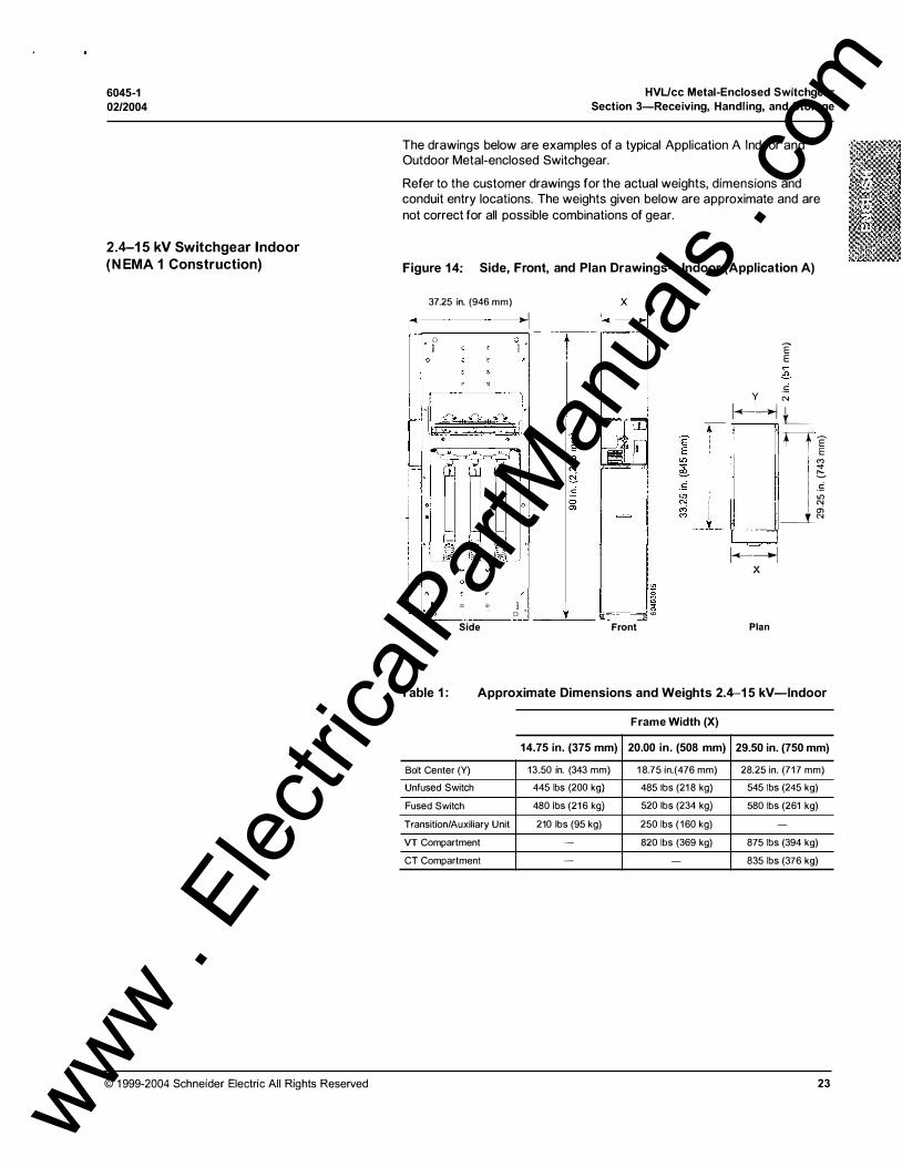
2.4-15 kV Switchgear Indoor (NEMA 1 Construction)
© 1 999-2004 Schneider Electric All Rights Reserved
HVUcc Metal-Enclosed Switchgear Section 3-Receiving, Handling, and Storage
The drawings below are examples of a typical Application A Indoor and Outdoor Metal-enclosed Switchgear.
Refer to the customer drawings for the actual weights, dimensions and conduit entry locations. The weights given below are approximate and are not correct for all possible combinations of gear.
Figure 14: Side, Front, and Plan Drawings-Indoor (Application A)
37.25 in. (946 mm) �-��- ,...I ,---,--------, --�-
0 0 " � u
'-,...���,!.· � '--"� o 0 J" , .. lie '------------- ---'---- . �:::-.:____s m Side Front
'E E
.!: y N 1--iL_ tri
"' ..,. · !::;..
II� "!
:__i_ ?J
1--1 X
Plan
Table 1 : Approximate Dimensions and Weights 2.4-1 5 kV-Indoor
Frame Width (X)
14.75 in. (375 mm) 20.00 in. (508 mm) 29.50 in. (750 mm)
Bolt Center (Y) 13 .50 in. (343 mm) 1 8.75 in.(476 mm) 28.25 in. (71 7 mm)
Unfused Switch 445 lbs (200 kg} 485 lbs (21 8 kg} 545 lbs (245 kg)
Fused Switch 480 lbs (21 6 kg} 520 lbs (234 kg} 580 lbs (261 kg)
Transition/Auxiliary Unit 210 lbs (95 kg) 250 lbs ( 160 kg) -
VT Compartment - 820 lbs (369 kg) 875 lbs (394 kg)
CT Compartment - - 835 lbs (376 kg)
23 www . El
ectric
alPar
tMan
uals
. com

HVL/cc Metal-Enclosed Switchgear
Section 3-Receiving, Handling, and Storage
2.4-15 kV Switchgear Outdoor (NEMA 3R Construction)
24
6045-1
02/2004
Figure 1 5: Side and Plan Drawing-Outdoor (Application A)
E' E ..,. "' L()
£{ -� L() ,.._ .,; Ol
l --
<= l � -
-
0 '-- 0
I_
_o_j �� 0 0 06 0 0 0 0
0 0
0 0
� o oe e eo o
¥ 0 'n 'n 'n 0 0
0 0 0 0
@ E � § @
0
�� Oo 0
0
0 0
J
E' E L() � -� � y •jj 'l<l
�· ·� '!"
�- + -� 1'-�-------:�-------::1 X
E' E Ol ..,.
:::::.
.� L() "' l!:i ..,.
47.25 in. (1 ,200 mm)
Side Plan
Table 2: Approximate Dimensions and Weights 2.4-1 5 kV-Outdoor
Frame Width (X)
14.75 in. (375 mm) 20.00 in. (508 mm) 29.50 in. (750 mm)
Bolt Center (Y) Add 2.25 in. (57 mm) to the total length of the switchgear lineup
Unfused Switch 585 lbs (263 kg) 655 lbs (295 kg) 785 lbs (353 kg)
Fused Switch 629 lbs (278 kg) 685 lbs (308 kg) 820 lbs (370 kg)
Transition/Auxiliary Unit 440 lbs (200 kg) 450 I bs (205 kg) -
VT Compartment - 985 lbs (443 kg) 1 1 1 51bs (502 kg)
CT Compartment - - 1075 lbs (484 kg)
End Panel End panels add 90 lbs (40.5 kg) per end unit
© 1999-2004 Schneider Electric All Rights Reserved
www . El
ectric
alPar
tMan
uals
. com
6045-1 02/2004
25.8-38 kV Switchgear Indoor (NEMA 1 Construction)
© 1999-2004 Schneider Electric All Rights Reserved
HVL/cc Metal-Enclosed Switchgear Section 3-Receiving, Handling, and Storage
Figure 1 6: Side, Front, and Plan Drawings-Indoor (Application A)
59. 12 in. ( 1502 mm) --�1 0 ----+--
0
J•�ld��!I!?)'''A I l•
� �� ·�� i � i i
X 1�-----i
'-- 0 0
---- �� Side Front
"E E 0 0 ....
-� N
.0 l()
y 1-<-->--1 L_
Plan
Table 3: Approximate Dimensions and Weights 25.8-38 kV-Indoor
Frame Width (X)
29.50 in. (750 mm) 39.37 in. (1000 mm)
Bolt Center (Y) 25.76 in. (654 mm) 35.63 in. (905 mm)
Unfused Switch 760 lbs (345 kg) 877 lbs. ( 400 kg)
Fused Switch 795 lbs (360 kg) 915 lbs (420 kg)
Transition/Auxiliary Unit 510 lbs (230 kg) 625 lbs (280 kg)
VT Compartment 1 090 lbs (495 kg) 1 200 lbs (545 kg
CT Compartment 1 050 lbs (475 kg) 1 160 lbs (525 kg)
25 www . El
ectric
alPar
tMan
uals
. com
HVL/cc Metal-Enclosed Switchgear
Section 3-Receiving, Handling, and Storage
25.8-38 kV Switchgear Outdoor (NEMA 3R Construction)
26
6045-1
02/2004
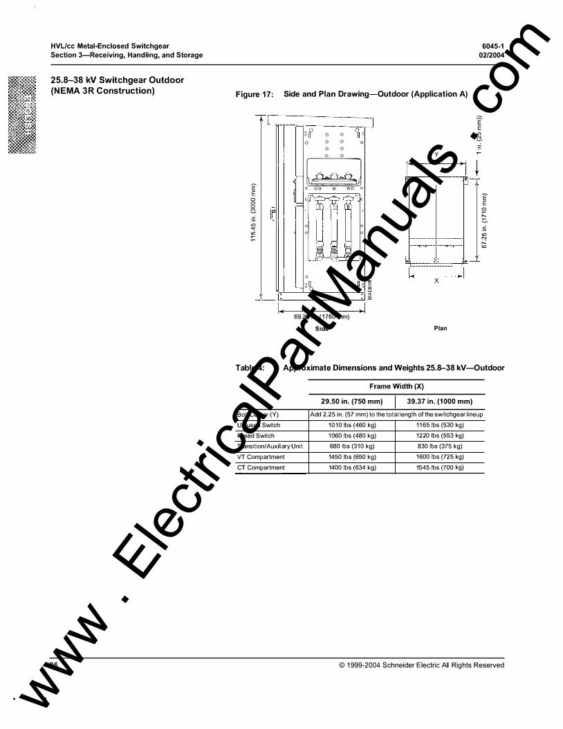
Figure 1 7: Side and Plan Drawing-Outdoor (Application A)
TL - -··
E' E 0 0 0 c .£ "' ..,. 00
"
0 -I.
q(' �
L_
�
-gf 0
0 0 0 0 0 0
0 0
0 0
� -
o oe
00 (]1 0 0
0
g�
§ 0 0
e eo o
� Loi � 'I
'§ § E 0 0 0 0
0 0
I I Qo
0 0 0 0
- I 69.25 in . ( 1 760 mm)
Side
E' E
"' � _!;;
y •Jj J• + ·� �·
d I ;_ ________ ��--- :Q -·
X
-�
Plan
E' E
0
t::: ::::.
.£ "' "' ,..: <D
Table 4: Approximate Dimensions and Weights 25.8-38 kV-Outdoor
Frame Width (X)
29.50 in. (750 mm) 39.37 in. (1 000 mm)
Bolt Center (Y) Add 2.25 in. (57 mm) to the total length of the switchgear lineup
Unfused Switch 1010 lbs (460 kg) 1 1 65 lbs (530 kg)
Fused Switch 1060 lbs (480 kg) 1220 lbs (553 kg)
Transition/Auxiliary Unit 680 lbs (310 kg) 830 lbs (375 kg)
VT Compartment 1450 lbs (650 kg) 1600 lbs (725 kg)
CT Compartment 1400 lbs (634 kg) 1545 lbs (700 kg)
© 1999-2004 Schneider Electric All Rights Reserved
www . El
ectric
alPar
tMan
uals
. com

6045-1 02/2004
HVL/cc Metal-Enclosed Switchgear Section 4-lnstallation
SECTION 4 -INSTALLATION
SITE PREPARATION
© 1999-2004 Schneider Electric All Rights Reserved
This chapter contains instructions for the installation of the equipment. Perform the installation in the following sequence:
- Site Preparation
- Switch Operation
- Access Panel Removal
Field Assembly
Cable Connections
Fuse Inspection/Replacement (if necessary)
Hi-pot Testing
Good site preparation is necessary to eliminate installation problems and ensure proper switchgear operation . Compare the site plans and specifications with the switchgear drawings to be sure there are no discrepancies. Check the site to ensure that the equipment will fit properly (see Tables 1 , 2, 3, and 4 on pages 23-26).
The floor should be flat and level within 1 / 16 inch per foot (2 mm per 305 mm ),
or a maximum of 1 /4 inch (6 mm) within the area of the switchgear, to prevent distortion of the enclosures.
The equipment has been designed for front access. Schneider Electric recommends that the rear of indoor equipment be placed a minimum of 4-6 inches from the wal l . Allow 5 feet ( 1 , 524 mm) of clearance on the front and sides. However, minimum clearances must meet all local and national requirements.
On outdoor switchgear, 5 feet of clearance (on the front and back only) is recommended.
Provide area ventilation at all times to maintain the ambient temperature around the equipment between 0 oc and 40 oc degrees (see "Preventive Maintenance" on page 46).
Adequate lighting and convenience outlets should be available near the switchgear. Route sewer, water, and steam lines away from the equipment. Provide floor drains to prevent water buildup.
A DANG ER HAZARD O F ELECTRIC SHOCK, BURN, O R EXPLOSION.
Before installing, removing, or performing any work on or inside the switchgear:
Turn off the power supply to the switchgear. Wear personal protective equipment appropriate for the hazard, including insulated gloves and face shield. Turn off the switchgear before removing or installing fuses or making load-side connections Always use a properly rated voltage sensing device at all line and load-side fuse clips to confirm that the switchgear is off. Never operate the switchgear with the access panels open.
Failure to follow these instructions will result in death, serious injury,
or equipment damage.
27 www . El
ectric
alPar
tMan
uals
. com
HVL!cc Metal-Enclosed Switchgear
Section 4-lnstallation
OPERATING THE SWITCHES
Operating the Ground Switch (if equipped)
28
6045-1
02/2004
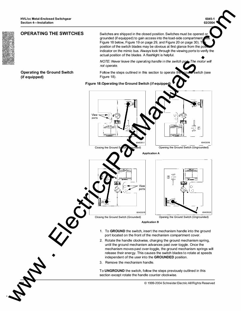
Switches are shipped in the closed position. Switches must be opened or grounded (if equipped) to gain access into the load-side compartment (see Figure 1 8 below, Figure 19 on page 29, and Figure 20 on page 30). The position of the switch blades may be obvious at first glance from the position indicator on the mimic bus. Always look through the viewing ports to verify the actual position of the blades. A flashlight is helpful.
NOTE: Never leave the operating handle in the switch port. The motor will not operate.
Follow the steps outlined in this section to operate the ground switch (see Figure 1 8).
Figure 18:0perating the Ground Switch (if equipped)
View � � �· ports
() o
6045301 7
Closing the Ground Switch (Grounded)
J -0 rn 0 ......
60453018
Opening the Ground Switch (Ungrounded)
Application A
��o � View
;J,L 0 � ports
60453019
Closing the Ground Switch (Grounded)
Application B
rn a: r
60453020
Opening the Ground Switch (Ungrounded)
1 . To GROUND the switch, insert the mechanism handle into the ground port located on the front of the mechanism compartment cover.
2. Rotate the handle clockwise, charging the ground mechanism spring, until the ground mechanism advances past over-toggle . Once the mechanism moves past over-toggle, the ground mechanism springs will release their energy. This causes the switch blades to rotate at speeds independent of the user into the GROUNDED position .
3 . Remove the mechanism handle.
To UNGROUND the switch, follow the steps previously outlined in this section except rotate the handle counter clockwise.
© 1 999-2004 Schneider Electric All Rights Reserved
www . El
ectric
alPar
tMan
uals
. com

6045-1 0212004
Operating Switchgear Equipped With an OTM
© 1999-2004 Schneider Electric All Rights Reserved
HVL/cc Metal-Enclosed Switchgear Section 4-lnstallation
Follow the steps outlined in this section to operate switches equipped with an OTM (see Figure 1 9).
Figure 19:Switchgear Operation (OTM)
60453021 60453022
Closing the Switch (OTM) Opening the Switch (OTM)
Application A
60453023 60453024
Closing the Switch with an OTM Mechanism Opening the Switch with an OTM Mechanism
Application B
1 . To OPEN (0) the switch, insert the mechanism handle into the switch operating port located on the front of the mechanism compartment cover.
2. Rotate the handle counter-clockwise, until the operating mechanism advances beyond over-toggle.
NOTE: Rotating the handle charges the open/close springs of the operating mechanism. Once the mechanism moves beyond over-toggle, the operating mechanism springs will release their energy. This causes the switch blades to rotate at speeds independent of the user into the OPEN position.
3. Remove the mechanism handle.
To CLOSE (I) the switch, follow the steps previously outlined in this section except rotate the handle clockwise.
29 www . El
ectric
alPar
tMan
uals
. com

HVL/cc Metal-Enclosed Switchgear
Section 4-lnstallation
Operating Switchgear Equipped With an SEM
Figure 20: Switchgear Operation (SEM)
60453025
Charging the Springs with an SEM Mechanism
60453028
Charging the Springs with an SEM Mechanism
30
6045-1
02/2004
Follow the steps outlined in this section to operate switches equipped with an SEM (see Figure 20).
60453026
Closing the Switch with an SEM Mechanism
Application A
60453029
Closing the Switch with an SEM Mechanism
Application B
0
60453027
Opening the Switch with an SEM Mechanism
0
r:=.:_·]
60453030
Opening the Switch with an SEM Mechanism
1 . Press the OPEN (0) push button. The operating mechanism springs will release their energy, causing the switch blades to rotate into the OPEN position.
2. To CLOSE {I) the switch, insert the mechanism handle into the spring charging port located on the front of the mechanism compartment cover.
3. Rotate the handle clockwise to charge the open/close springs of the operating mechanism.
4. Continue to rotate the handle until the spring charge indicator shows that the springs have been fully charged. Both the open and close springs are now charged.
5. Remove the mechanism handle.
6. Press the CLOSE {I) push button . The operating mechanism springs will release their energy, causing the switch blades to rotate into the CLOSE
position (the opening springs remain charged).
© 1999-2004 Schneider Electric All Rights Reserved
www . El
ectric
alPar
tMan
uals
. com
6045-1 02/2004
ACCESS PANEL REMOVAL
Removing the Load-side Access Panels
© 1999-2004 Schneider Electric All Rights Reserved
HVUcc Metal-Enclosed Switchgear Section 4-lnstallation
After the switch has been placed in the OPEN or GROUNDED (if equipped) position, remove al l appropriate access panels. Removal of these panels will al low the user to access the necessary compartments in order to anchor and join shipping split frames, make bus and cable connections, install and/or remove fuses, and perform Hi-pot (dielectric) tests and pre-energization inspections.
Instructions for removing the load-side access panel are listed below. All other panels are bolted. The instrument compartment panel cannot be removed.
Follow the instructions l isted below for removing the load-side access panels for Application A indoor or outdoor switchgear (see Figure 21 ):
Figure 21 : Removing the Load-side Access Panel-Application A
(Step 3) ,.
NOTE: Tab must fit in slot
60453031
1 . Verify that the switch is in the OPEN or GROUNDED (if equipped) position .
NOTE: If the switchgear is equipped with a grounding switch, the switch must be in the GROUNDED position.
2. Grasp the handle on the front of the access panel firmly and lift the access panel until the interlock tab clears the interlock slot.
3. Tilt (pull) the panel out until it clears the front of the switchgear.
31 www . El
ectric
alPar
tMan
uals
. com
HVL/cc Metal-Enclosed Switchgear
Section 4-lnstallation
FIELD ASSEMBLY
32
6045-1
02/2004
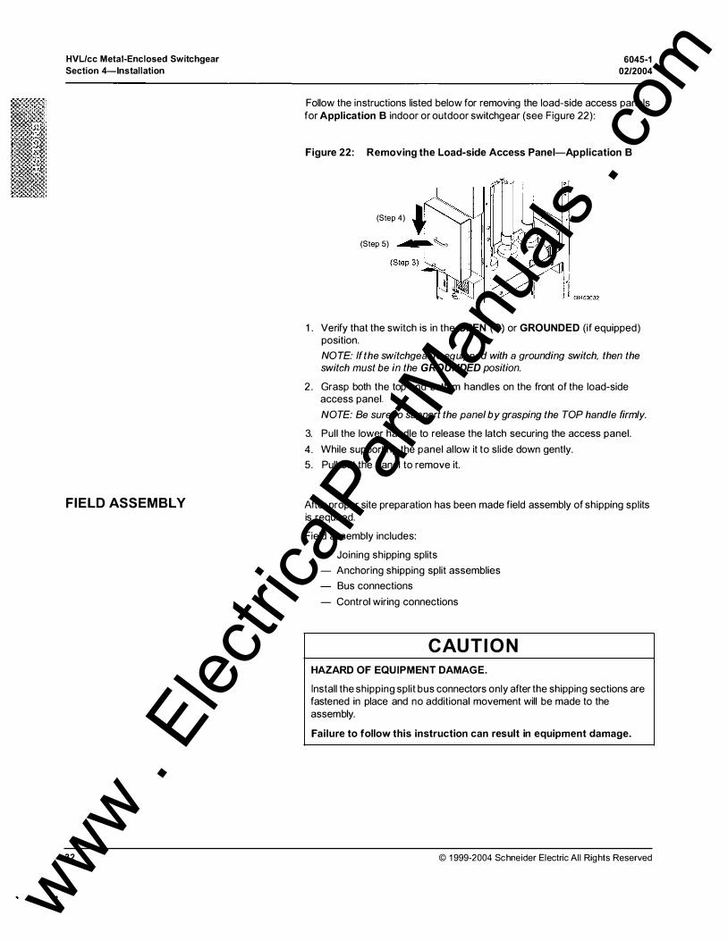
Follow the instructions listed below for removing the load-side access panels for Application B indoor or outdoor switchgear (see Figure 22):
Figure 22: Removing the Load-side Access Panel-Application B
(Step 4)
(Step 5)
1 . Verify that the switch is in the OPEN (0) or GROUNDED (if equipped) position.
NOTE: If the switchgear is equipped with a grounding switch, then the switch must be in the GROUNDED position.
2 . Grasp both the top and bottom handles on the front of the load-side access panel.
NOTE: Be sure to support the panel by grasping the TOP handle firmly.
3. Pull the lower handle to release the latch securing the access panel.
4. While supporting the panel al low it to slide down gently.
5. Pull out the panel to remove it.
After proper site preparation has been made field assembly of shipping splits is required.
Field assembly includes:
- Joining shipping splits
- Anchoring shipping split assemblies
Bus connections
- Control wiring connections
CAUTION HAZARD OF EQUIPMENT DAMAGE.
Install the shipping split bus connectors only after the shipping sections are fastened in place and no additional movement will be made to the assembly.
Failure to follow this instruction can result in equipment damage.
© 1999-2004 Schneider Electric Al l Rights Reserved
www . El
ectric
alPar
tMan
uals
. com
6045-1 02/2004
Anchoring and Joining the Shipping Split Frames
Indoor Shipping Splits
Outdoor Shipping Splits
HVL/cc Metal-Enclosed Switchgear
Section 4-lnstallation
Follow the steps listed below for joining and anchoring shipping split frames.
1 . Review the assembly drawings to ensure that the switchgear sections will be assembled in the correct order.
NOTE: If the switchgear will connect to an existing lineup, mount the connecting sections first.
2. Locate and anchor the first shipping split.
NOTE: Be sure to mount all shipping splits on the same plane and level them to ensure proper connection.
Follow the instructions below for anchoring indoor or outdoor units.
To anchor indoor shipping split frames to the floor, place the 3/8 in . anchoring bolts (supplied by customer) through the anchoring holes located in the flanges at the bottom of each enclosure (see Figure 23).
Figure 23: Bolt Hole Locations for Indoor Enclosures
J t t 60453033
NOTE: Arrows indicate anchoring bolt holes positions
a. Remove the lifting angle assemblies. Retain the hardware and lifting angle assembly parts for future use. The angle is to be used for anchoring the shipping split. The flat plate is to be used as a rodent barrier.
b. Rotate the angle and attach it to the side of the shipping split using the hardware retained in Step a.
c. To anchor the enclosure to the foundation, place 3/4 in. anchoring bolts through the holes in the anchoring angles (see Figure 24).
Figure 24: Anchoring Assemblies for Outdoor Enclosures
Flat plate-flip horizontally and reattach as rodent barrier
Anchor angles in lifting position
Angle plate-rotate counter-clockwise and use as anchoring angle
60453034
© 1999-2004 Schneider Electric All Rights Reserved
.--..,-------- Bolt holes for attaching the angles to the enclosure
Anchor angles in anchoring position
33
www . El
ectric
alPar
tMan
uals
. com

HVL!cc Metal-Enclosed Switchgear
Section 4-lnstallation
34
3 . Locate the next shipping split according to the assembly drawing.
6045-1
02/2004
4 . Level the shipping split and join it to the previously installed shipping split. Use 3/8-1 6, Grade 5 hardware to join shipping splits. Refer to Figure 25 for bolt hole locations.
Figure 25:Joining the Shipping Splits and Installing the End Panels
+- 0 � f.. � 8 0
0 0 8 0
0 0
0 0
J= ·L�� �� ��J . .
"". " .. ..
�fo 1 :iJ � ..
.
•
� I§ � I§ 0
0
0 0
l:ll! � 0
� � 0
0
0
0
0
0
0
J �
(Cross-sectional view of connected panels)
NOTE: Arrows indicate shipping split and end panel bolt locations
5. Anchor the shipping split.
'"" �
/ � :1/
60453036
For indoor units, place the 3/8 in . anchoring bolts (supplied by customer) through the anchoring holes located in the flanges at the bottom of the enclosure (see Figure 26). See Table 5 on page 36 for torque values.
Figure 26: Anchoring Subsequent Indoor Shipping Splits
TOP VIEW
Shipping Split 1
Shipping Split
NOTE: Arrows indicate anchoring bolt holes
2 , I
60453037
© 1999-2004 Schneider Electric Al l Rights Reserved
www . El
ectric
alPar
tMan
uals
. com
6045-1 02/2004
Bus Connections
© 1999-2004 Schneider Electric All Rights Reserved
HVUcc Metal-Enclosed Switchgear Section 4-lnstallation
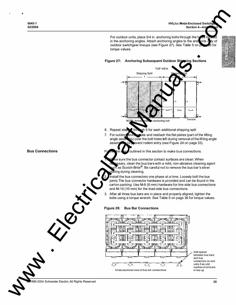
For outdoor units, place 3/4 in. anchoring bolts through the holes located in the anchoring angles. Attach anchoring angles to the end units only of outdoor switchgear l ineups (see Figure 27). See Table 5 on page 36 for torque values.
Figure 27: Anchoring Subsequent Outdoor Shipping Sections
Shipping Split 1
TOP VIEW
0
NOTE: Arrows indicate anchoring bolt
Shipping Split 2
0 0
60453038
6. Repeat steps 3 through 5 for each additional shipping split
7. For outdoor units, rotate and reattach the flat plates (part of the lifting angle assembly) over the bolt holes left during removal of the lifting angle assemblies to prevent rodent entry (see Figure 24 on page 33) .
Follow the steps outlined in this section to make bus connections.
1 . Make sure the bus connector contact surfaces are clean. When necessary, clean the bus bars with a mild, non-abrasive cleaning agent such as Scotch-Brite®. Be careful not to remove the bus bar's silver plating during cleaning.
2. Install the bus connectors one phase at a t ime. Loosely bolt the bus joints. The bus connector hardware is provided and can be found in the carton packing. Use M-8 (8 mm) hardware for l ine side bus connections and M-1 0 ( 1 0 mm) for the load-side bus connections.
3. After all three bus bars are in place and properly aligned, tighten the bolts using a torque wrench. See Table 5 on page 36 for torque values.
Figure 28: Bus Bar Connections
Cross-sectional view of bus bar connections
Add spacer between bus bars and bus connectors on end units if an odd number of units are in line-up
35
www . El
ectric
alPar
tMan
uals
. com
HVUcc Metal-Enclosed Switchgear Section 4-lnstallation
Control Wiring Connections
36
6045-1
02/2004
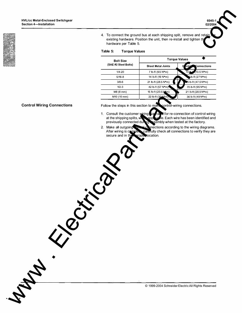
4. To connect the ground bus at each shipping split, remove and retain the existing hardware. Position the unit, then re-install and tighten the hardware per Table 5.
Table 5: Torque Values
Bolt Size Torque Values
(SAE #2 Steel Bolts) Sheet Metal Joints Electrical Connections
1/4-20 7 lb-ft (9.5 N"m) 10 lb-ft (13.5 N•m)
5/16-8 14 lb-ft (19 N•m) 20 lb-ft (27 N•m)
3/8-6 21 lb-ft (28.5 N"m) 35 1b-ft (47.5 N•m)
1/2-3 42 lb-ft (57 N•m) 70 lb-ft (95 N"m)
M8 (8 mm) 15 lb-ft (20.5 N"m) 21 lb-ft (28.5 N•m)
M10 (10 mm) 22 lb-ft (30 N•m) 36 lb-ft (49 N"m) -·
Follow the steps in this section to make control-wiring connections.
1. Consult the customer wiring diagrams for re-connection of control wiring at the shipping splits, when applicable. Each wire has been identified and previously connected during assembly when tested at the factory.
2. Make all outgoing control connections according to the wiring diagrams. After wiring is complete, carefully check all connections to verify they are secure and in their proper location.
© 1999-2004 Schneider Electric All Rights Reserved
www . El
ectric
alPar
tMan
uals
. com
6045-1 02/2004
CABLE CONNECTIONS
Forming the Cables
Shielded Cables Through Window-Type Current Transformers
© 1999-2004 Schneider Electric All Rights Reserved
HVL/cc Metal-Enclosed Switchgear Section 4-lnstallation
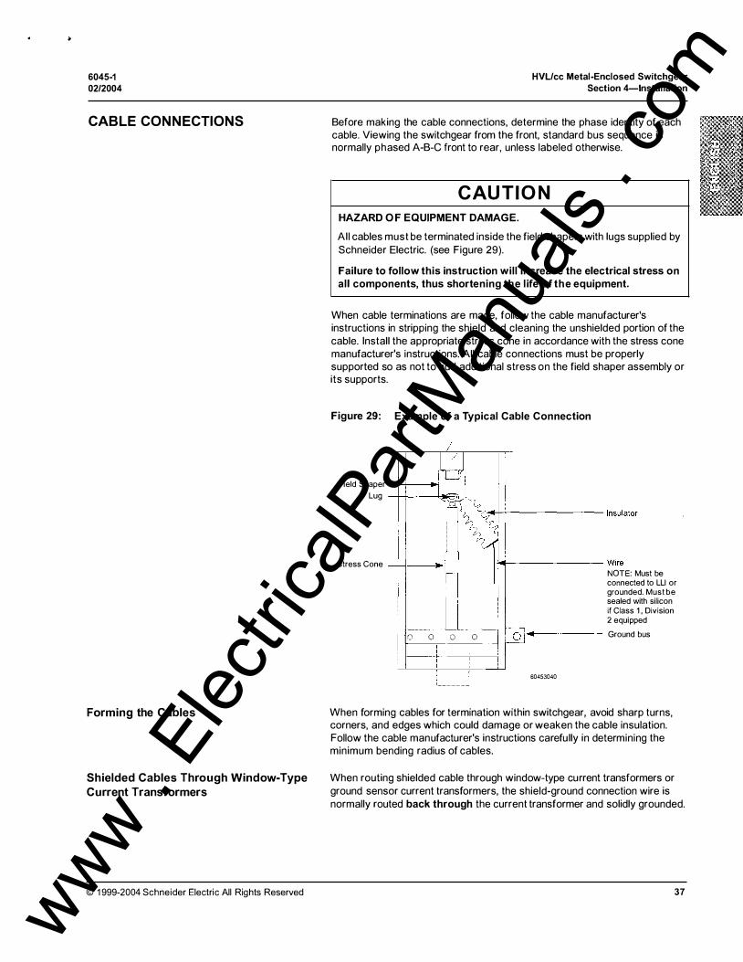
Before making the cable connections, determine the phase identity of each cable. Viewing the switchgear from the front, standard bus sequence is normally phased A-B-C front to rear, unless labeled otherwise.
CAU TION HAZARD O F EQUIPMENT DAMAGE.
All cables must be terminated inside the field shapers with lugs supplied by Schneider Electric. (see Figure 29).
Failure to follow this instruction will increase the electrical stress on all components, thus shortening the l ife of the equipment.
When cable terminations are made, follow the cable manufacturer's instructions in stripping the shield and cleaning the unshielded portion of the cable. Install the appropriate stress cone in accordance with the stress cone manufacturer's instructions. All cable connections must be properly supported so as not to add additional stress on the field shaper assembly or its supports.
Figure 29: Example of a Typical Cable Connection
/I
Field Shaper -+-+---.tlb Lug ,�-CC��
I !/�--;
,�·,_.
'-[
++---
---- I nsulator
Stress Cone -+-t-----11�1 �------- Wire NOTE: Must be connected to LLI or grounded. Must be sealed with silicon if Class 1 , Division
____ .L__l.___---j G 0 0 0 I
'-------
2 equipped r--o'1------ Ground bus
60453040
When forming cables for termination within switchgear, avoid sharp turns, corners, and edges which could damage or weaken the cable insulation. Follow the cable manufacturer's instructions carefully in determining the minimum bending radius of cables.
When routing shielded cable through window-type current transformers or ground sensor current transformers, the shield-ground connection wire is normally routed back through the current transformer and solidly grounded.
37 www . El
ectric
alPar
tMan
uals
. com
HVL/cc Metal-Enclosed Switchgear
Section 4-lnstallation
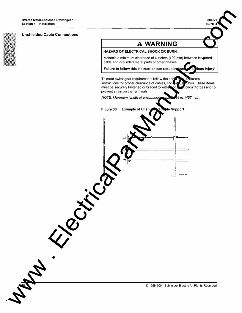
Unshielded Cable Connections
38
A WARNING HAZARD OF ELECTRICAL SHOCK OR BURN.
6045-1
0212004
Maintain a minimum clearance of 4 inches (1 02 mm) between insulated cable and grounded metal parts or other phases.
Failure to follow this instruction can result in death or serious injury!
To meet switchgear requirements follow the cable manufacturers instructions for proper clearance of cables, conduits, and bus. These items must be securely fastened or braced to withstand short circuit forces and to prevent strain on the terminals.
NOTE: Maximum length of unsupported cable is 1 8 in. (457 mm).
Figure 30: Example of Unshielded Cable Support
0
0
60453041
© 1999-2004 Schneider Electric Al l Rights Reserved
www . El
ectric
alPar
tMan
uals
. com
6045-1 02/2004
FUSE REPLACEMENT
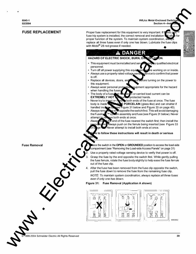
Fuse Removal
© 1999-2004 Schneider Electric All Rights Reserved
HVL/cc Metal-Enclosed Switchgear Section 4-lnstallation
Proper fuse replacement for this equipment is very important. If FuseLogic™ fuse trip system is installed, the correct removal and installation will allow for proper function of the system. To maintain system coordination, always replace all three fuses even if only one has blown. Lubricate the fuse clips with Mobil® 28 red grease if needed .
A DANG ER HAZARD O F ELECTRIC SHOCK, BURN, O R EXPLOSION.
• This equipment must be installed and serviced only by qualified electrical personnel.
• Turn off all power supplying this equipment before working on or inside. • Always use a properly rated voltage sensing device to confirm that power
is off. • Replace all devices, doors, and covers before turning on the power to
this equipment. • Always wear personal protective equipment appropriate for the hazard
when handling the fuses. • The body of a fuse that has blown or carried load current can be
EXTREMELY HOT and burn unprotected hands. • Never try to insert or remove both ends of the fuse at once. The fuse
body is made of FRAGILE PORCELAIN (glass-like) and can shatter if handled incorrectly (see Figure 3 1 below and Figure 33 on page 40).
• Always remove the end opposite the switch first. This will avoid damaging the Fuselogic™ system assembly and fuse (see Figure 31 below). Never attempt to remove both ends at once.
• Always install the end of the fuse nearest the switch first; then install the opposite end . Always push on the ferrule being inserted (see Figure 33 on page 40). Never attempt to install both ends at once.
Failure to fol low these instructions will result in death or serious injury.
1 . Place the switch in the OPEN or GROUNDED position to access the load-side compartment (see "Removing the Load-side Access Panels" on page 3 1 )
2 . Use a properly rated voltage sensing device to verify that power i s off.
3 . Grasp the fuse by the end opposite the switch first. While gently pulling the fuse ferrule, rotate the fuse body slightly to help ease the fuse ferrule out of the fuse clip.
4. After the fuse has been removed from the fuse clip opposite the switch, pull the fuse down to remove the fuse from the remaining fuse clip.
NOTE: To maintain system coordination, always replace all three fuses even if only one has blown.
Figure 31: Fuse Removal (Application A shown)
60453042
39 www . El
ectric
alPar
tMan
uals
. com

•
HVL/cc Metal-Enclosed Switchgear
Section 4-lnstallation
Fuse Installation
40
Follow the steps outlined below to install fuses
6045-1
02/2004
1 . Using a properly rated voltage sensing device verify that power is off.
2 . Insert the fuse ferrule into the fuse clip that is nearest the switch (Top on Application A, Bottom on Application B). Be sure to orient the striker pin properly (see Figure 32)
NOTE: The striker pin assembly must always point toward the switch. For
Application A the pin is at the top of the fuse. On Application B the pin must be at the bottom. The fuse characteristics and striker pin directions are printed on the fuse label. Always turn the fuse so that the label is in the front and the arrow is pointed toward the switch (up-Application A, down-Application B).
Figure 32: Fuse Characteristics and Striker Pin Directions (Application A position shown)
Striker Pin (used in indicating option)
Ferrule
Fuse Label
Fuse Body
60453043
3 . Insert the remaining end of the fuse into the fuse clip opposite the switch. Gently push while rotating the fuse body to help ease the fuse ferrule into the fuse clip.
NOTE: Never insert both ends at once.
Figure 33: Fuse Installation (Application A shown)
! '1� 1 L-�
]f.L] ··?{·"
·
:·) -Ci:,?�l.· .. ;': 1
I I i � : i [-n�� ' I , [_),. . ..;::! .. : �bi �· - � -t:"L_� 60453044
© 1999-2004 Schneider E lectric All Rights Reserved
www . El
ectric
alPar
tMan
uals
. com
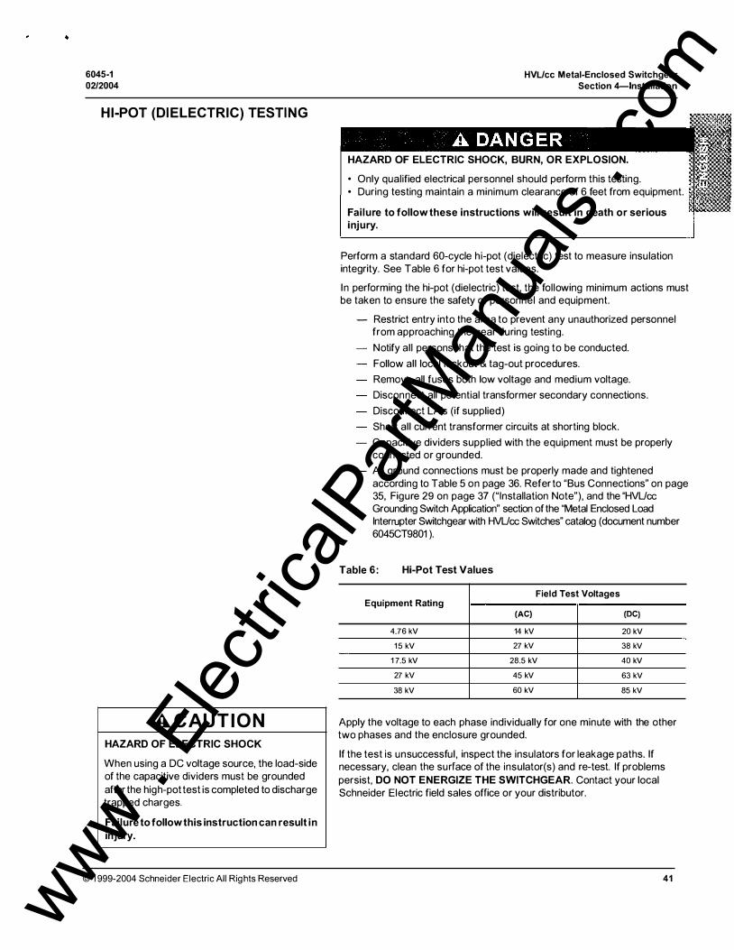
6045-1 02/2004
HI-POT (DIELECTRIC) TESTING
A C AU TION HAZARD OF ELECTRIC SHOCK
When using a DC voltage source, the load-side of the capacitive dividers must be grounded after the high-pot test is completed to discharge trapped charges.
Failure to follow this instruction can result in
injury.
© 1999-2004 Schneider Electric All Rights Reserved
HVL/cc Metal-Enclosed Switchgear Section 4-lnstallation
HAZARD OF ELECTRIC SHOCK, BURN, OR EXPLOSION.
• Only qualified electrical personnel should perform this testing. • During testing maintain a minimum clearance of 6 feet from equipment.
Failure to follow these instructions will result in death or serious injury.
Perform a standard 60-cycle hi-pot (dielectric) test to measure insulation integrity. See Table 6 for hi-pot test values.
In performing the hi-pot (dielectric) test, the following minimum actions must be taken to ensure the safety of personnel and equipment.
- Restrict entry into the area to prevent any unauthorized personnel from approaching the gear during testing.
Notify all persons that the test is going to be conducted.
Follow all local lockout & tag-out procedures.
Remove all fuses both low voltage and medium voltage.
Disconnect all potential transformer secondary connections.
Disconnect LA's (if supplied)
Short all current transformer circuits at shorting block.
Capacitive dividers supplied with the equipment must be properly connected or grounded.
- All ground connections must be properly made and tightened according to Table 5 on page 36. Refer to "Bus Connections" on page 35, Figure 29 on page 37 ("Installation Note"), and the "HVUcc Grounding Switch Application" section of the "Metal Enclosed Load Interrupter Switchgear with HVUcc Switches" catalog (document number 6045CT9801).
Table 6: Hi-Pot Test Values
Field Test Voltages Equipment Rating
(AC) (DC)
4.76 kV 14 kV 20 kV
1 5 kV 27 kV 38 kV
1 7.5 kV 28.5 kV 40 kV
27 kV 45 kV 63 kV
38 kV 60 kV 85 kV
Apply the voltage to each phase individually for one minute with the other two phases and the enclosure grounded.
If the test is unsuccessful , inspect the insulators for leakage paths. If necessary, clean the surface of the insulator(s) and re-test. If problems persist, DO NOT ENERGIZE THE SWITCHGEAR. Contact your local Schneider Electric field sales office or your distributor.
41
www . El
ectric
alPar
tMan
uals
. com
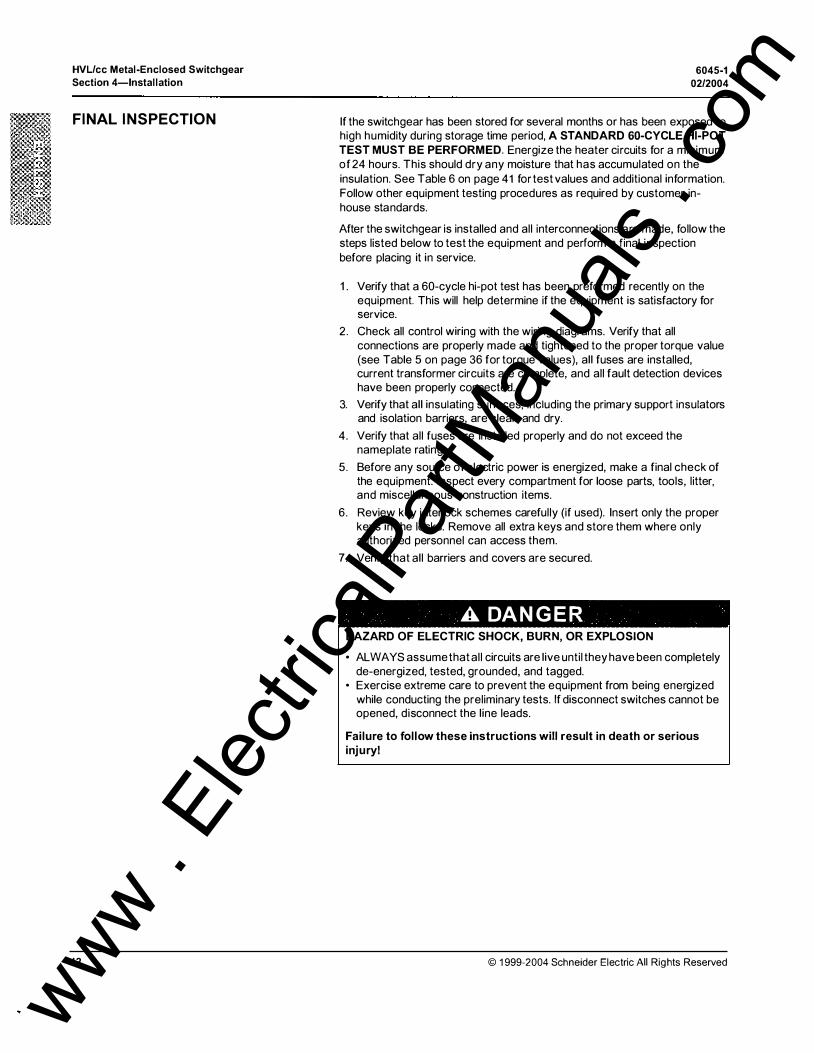
HVL/cc Metal-Enclosed Switchgear
Section 4-lnstallation
FINAL INSPECTION
42
6045-1
02/2004
If the switchgear has been stored for several months or has been exposed to high humidity during storage time period, A STANDARD GO-CYCLE HI-POT
TEST MUST BE PERFORMED. Energize the heater circuits for a minimum of 24 hours. This should dry any moisture that has accumulated on the insulation. See Table 6 on page 41 for test values and additional information. Follow other equipment testing procedures as required by customer inhouse standards.
After the switchgear is installed and all interconnections are made, follow the steps listed below to test the equipment and perform a final inspection before placing it in service.
1 . Verify that a 60-cycle hi-pot test has been preformed recently on the equipment. This will help determine if the equipment is satisfactory for service.
2. Check all control wiring with the wiring diagrams. Verify that all connections are properly made and tightened to the proper torque value (see Table 5 on page 36 for torque values), all fuses are installed, current transformer circuits are complete, and all fault detection devices have been properly connected.
3. Verify that all insulating surfaces, including the primary support insulators and isolation barriers, are clean and dry.
4. Verify that all fuses are installed properly and do not exceed the nameplate rating.
5. Before any source of electric power is energized, make a final check of the equipment. Inspect every compartment for loose parts, tools, l itter, and miscellaneous construction items.
6. Review key interlock schemes carefully (if used). Insert only the proper keys in the locks. Remove all extra keys and store them where only authorized personnel can access them.
7. Verify that all barriers and covers are secured.
A DANG E R HAZARD OF ELECTRIC SHOCK, BURN, OR EXPLOSION
• ALWAYS assume that al l circuits are live until they have been completely de-energized, tested, grounded, and tagged.
• Exercise extreme care to prevent the equipment from being energized while conducting the preliminary tests. If disconnect switches cannot be opened, disconnect the line leads.
Failure to fol low these instructions will result in death or serious injury!
© 1999-2004 Schneider Electric All Rights Reserved
www . El
ectric
alPar
tMan
uals
. com

6045-1 02/2004
HVL/cc Metal-Enclosed Switchgear Section 5-Final Preparation and Energization
SECTION 5- FINAL PREPARATION AND ENERGIZATION
FINAL OPERATING CHECKS
ENERGIZATION
© 1999-2004 Schneider Electric All Rights Reserved
This chapter contains information on how to operate HVUcc Metal-Enclosed Switchgear.
The following is a minimum list of operating tests that should be performed before energization.
NOTE: If any of the operating tests provide unacceptable results, DO NOT ENERGIZE THE SWITCHGEAR. Contact your local Schneider Electric field sales office or distributor.
With al l power off, perform the following checks:
1 . Operate the grounding switch (if equipped) a minimum of five times and verify that the LDA (if equipped) is functioning properly. (All contact fingers should touch the field shapers when the main switch is in the grounded position.)
2 . Operate the load switch a minimum of five times.
3. With the switch in the CLOSE position, verify that the load-side panel cannot be removed (see "Removing the Load-side Access Panels" on page 3 1 ).
4. When mechanical interlocks are present for automatic transfer or duplex switching, verify that only one switch will operate at a time.
5. Verify that the CT circuits are not shorted at the terminal block.
6. Replace all devices, doors, and covers before turning on the power to the equipment.
After the proper testing has been completed on the incoming service cables and before the switch is energized, perform the following operations.
1 . Open the incoming main switch.
2. Energize the incoming cables.
3. The optional Live Line Indicators (Llls), if supplied, are located on the main source side of the line-up. ( See Figure 34.) The optional Llls will indicate voltage when the equipment is energized.
Figure 34: Using Live Line Indicators
i cQ) cQ) © 0 0 0
- -
NOTE: As soon as the circuits have been energized the voltage indicator lamps should illuminate.
Neon (light)
Test Port
� 60453045
43 www . El
ectric
alPar
tMan
uals
. com
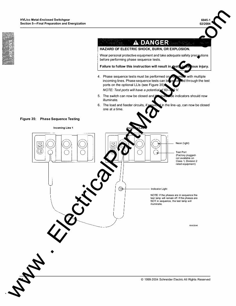
•
HVL/cc Metal-Enclosed Switchgear
Section 5-Final Preparation and Energization
Figure 35: Phase Sequence Testing
Incoming Line 1
r
� g g g 0 0
'-
44
A DAN G HAZARD OF ELECTRIC SHOCK, BURN, OR EXPLOSION.
6045-1
02/2004
Wear personal protective equipment and take adequate safety precautions before performing phase sequence tests.
Failure to follow this instruction will result in death or serious injury.
4. Phase sequence tests must be performed on equipment with multiple incoming lines. Phase sequence tests can be performed through the test ports on the optional Llls (see Figure 35).
NOTE: Test ports will have a potential of 60-400 V.
5. The switch can now be closed and the load-side indicators should now i l luminate.
6. The load and feeder circuits, if provided in the line-up, can now be closed one at a time.
�
...._____......
Incoming Line 2
g g 0
Indicator Light
NOTE: If the phases test lamp will remain NOT in sequence, t� i l luminate.
Neon (l ight)
Test Port (Factory pluggednot available on Class 1, Division 2 rated equipment)
are in sequence the off. If the phases are e test lamp will
60453046
© 1999-2004 Schneider Electric Al l Rights Reserved
www . El
ectric
alPar
tMan
uals
. com
•
6045-1 02/2004
HVL/cc Metal-Enclosed Switchgear Section 6-lnspection, Maintenance, and Troubleshooting
SECTION 6-INSPECTION, MAINTENANCE, AND TROUBLESHOOTING
INSPECTION/PREVENTATIVE MAINTENANCE GUIDELINES
Inspection
Recommended Inspection Interval
Inspection Procedure
© 1999-2004 Schneider Electric All Rights Reserved
This chapter contains the following sections:
"Inspection/Preventative Maintenance Guidelines" on page 45
"Replacement Parts" on page 49
"Corrective Maintenance" on page 51
"Class 1 , Division 2 Maintenance Requirements" on page 53
"Troubleshooting" on page 54
This section contains information on inspecting and performing preventive maintenance on HVUcc Metal-Enclosed Switchgear.
A DANG ER HAZARD OF ELECTRIC SHOCK, BURN, O R EXPLOSION
• This equipment must be installed and serviced only by qual ified electrical personnel.
• Turn off al l power supplying this equipment before working on or inside. • Always use a properly rated voltage sensing device to confirm that power
is off. • Beware of potential hazards, wear personal protective equipment and
take adequate safety precautions. • Before performing visual inspections, tests, or maintenance on the
equipment, disconnect all sources of electric power. Assume that all circuits are live until they have been completely de-energized, tested, grounded, and tagged. Pay particular attention to the design of the power system. Consider all sources of power, including the possibil ity of backfeeding.
• Replace all devices, doors, and covers before turning on the power to this equipment.
Failure to follow these instructions will result in death, serious injury or equipment damage!
Follow the guidelines and procedures outlined in this section when performing periodic inspections on the equ ipment .
Periodic inspection of the equipment is necessary to establish the conditions to which the units are subjected (see Table 7). The maximum recommended inspection interval is one year.
The following is a minimal list of inspection procedures that should be performed to ensure proper maintenance.
1 . Bus and Connections. De-energize the primary and secondary circuits. Perform a standard 60-cycle hi-pot test to measure bus insulation integrity (see "Hi-pot (Dielectric) Testing" on page 41 ).
2. Inspect the connections for symptoms which indicate overheating or weakened insulation . Remove dust from the surfaces of the bus bars, connections, supports, and enclosures. Wipe clean with a solvent such as denatured alcohol. Vacuum the equipment. Do not use compressed air to blow dust from the surfaces inside the switchgear.
45
www . El
ectric
alPar
tMan
uals
. com
.. .
HVL/cc Metal-Enclosed Switchgear
Section 6-lnspection, Maintenance, and Troubleshooting 6045-1
02/2004
Preventive Maintenance
Maintenance Log
Preventative Maintenance Intervals
46
3. Maintain the instruments, relays, and other devices according to the specific instructions supplied. Inspect the devices and their contacts for dust or dirt; wipe clean as necessary. The maintenance schedule for individual devices such as meters and relays should be based upon recommendations contained in the individual instruction manual for each device. Coordinate the various schedules with the overall maintenance program.
4. Inspect control wiring connections for tightness and damage.
5. Manually operate mechanical moving parts such as switch assemblies, interlocks, and doors.
6. Make sure all bus areas are well ventilated. Inspect grille work and air passages on indoor and outdoor switchgear to make sure they are free from obstruction and dirt accumulation. Clean aluminum filters on outdoor switchgear by removing and thoroughly back-flushing with soap and water. Replace the filters only after they are clean and dry.
Follow the guidelines and procedures in this section when performing preventative maintenance.
It is recommended that a maintenance log (see page 55) be kept for this equipment. Al l inspection, service and maintenance calls should be listed and dated as well as any corrective and preventive actions taken.
Periodic maintenance on the switchgear includes cleaning, lubrication, and exercising component parts. The interval between maintenance checks can vary depending upon the amount of usage and environmental conditions of each installation . This definition for periodic maintenance applies throughout this manual, unless otherwise noted.
Inspect the equipment immediately after abnormal or stressful operating conditions occur or after the equipment experiences a fault current.
Table 7: Recommended Maintenance Guidelines
Component Ideal Standard Aggressive
Conditions* Conditions* Conditions*
Epoxy Switch Housing Every 1 0 Years Every 5 Years Every 2 Years
Housing interior (all bus and mechanisms) Every 1 0 Years Every 5 Years Every 2 Years
Housing Every 1 0 Years �very 5 Years '--Every 2 Years
See "Environmental Conditions'' on page 47 for definitions.
These inspection/maintenance guidelines cover only the switch and enclosure manufactured by Schneider Electric. If conditions cannot be established and documented, then the aggressive operating condition must be assumed.
These inspection/maintenance guidelines do not warrant any field connections, field modifications, or supersede any maintenance procedures or schedules recommended by component manufacturers. For more information regarding the warranty of this product refer to "Schneider Electric Conditions of Sale", Doc. # 01 00PL9702 R8/98.
© 1 999-2004 Schneider E lectric All Rights Reserved
www . El
ectric
alPar
tMan
uals
. com

6045-1 02/2004
Environmental Conditions
© 1999-2004 Schneider Electric Al l Rights Reserved
Ideal Conditions:
HVUcc Metal-Enclosed Switchgear Section 6-lnspection, Maintenance, and Troubleshooting
1 . Unit is installed and commissioned in accordance with manufacturers instructions.
2. Humidity below 40% and no dripping water.
3 . Indoor protected from weather.
4. Minimum dust and air circulation.
5. Ambient temperature between -0° C and +40° C.
6. No contact with any chemical agents (salt, H2S, etc.).
7. No infestation of any animal life (rodents, insects, etc.).
8 . No contact with any plant life (mold, etc.).
9 . No earth movements.
10 . No damage to the unit of any kind.
1 1 . No mal-operation of any kind .
1 2. No abnormally high number of operations (see Figure 36 on page 48).
1 3 . No abnormally high number of faults (see Figure 36).
14 . No over-voltage or over-current (above ratings).
1 5 . Thermal scanning of the joints at-least once a year.
NOTE: (Optional thermal scanning windows or automatic scanning is available with the "Predictive Maintenance System" package offered by Schneider Electric).
Standard Conditions:
All the above conditions listed under "Ideal Conditions" apply with the exception of the following:
Number 2: Humidity below 60%.
- Numbers 3 through 5: The unit may be indoors or outdoors but must not be subjected to regular extremes of weather (heavy rainstorms, dust storms, flooding, temperature cycles greater than 40° C, temperatures less than minus 30° C, dense coastal fog or acid rain).
Number1 6: No regular thick covering of leaves or other debris.
Aggressive Conditions:
Any environmental conditions, which do not satisfy one of the two above descriptions, must be deemed aggressive.
This product is warranted per "Square D Condition of Sale"', Doc. # 01 OOPL9702 R 8/98 and has been tested under ideal laboratory conditions to the values listed below.
1 000 mechanical no load operations
1 00 full load current interruptions
3 fuse fault transfer current operations (see IEC 420 for application)
The device has been designed and tested to ANSI C37.20.4 and ANSI C37 .22, CSA C22.2, No. 1 93 , IEC 420 requirements. Figure 36 i l lustrates the typical life of the equipment under ideal laboratory conditions. This chart represents an accumulated total (ksi) at greater than 80% power factor, less than 1 7.5 kV of the 600 A interrupter.
NOTE: Example-The device will successfully interrupt 600 A current (nameplate rating) 100 times or 100 A current 600 times.
47 www . El
ectric
alPar
tMan
uals
. com

•
HVL/cc Metal-Enclosed Switchgear
Section 6-lnspection, Maintenance, and Troubleshooting 6045-1
02/2004
The contact life can also be verified by performing a mill ivoltage or micrometer test. The value should not increase by 300% of the original value of 80 micro-ohms using a 1 00 A test micrometer.
Figure 36: Typical Life of HVUcc (a) 25.8 and 38 kV, (b) 5 and 1 5 kV
1 0000
(f) 1 000 c 0
:;:::;
� Q) 0.. 0 -
1 00 0
05 .0
E :::J z
1 0
1 0 1 00 1 000 1 0000
Current Interrupted (Amperes)
48 © 1 999-2004 Schneider Electric All Rights Reserved
www . El
ectric
alPar
tMan
uals
. com
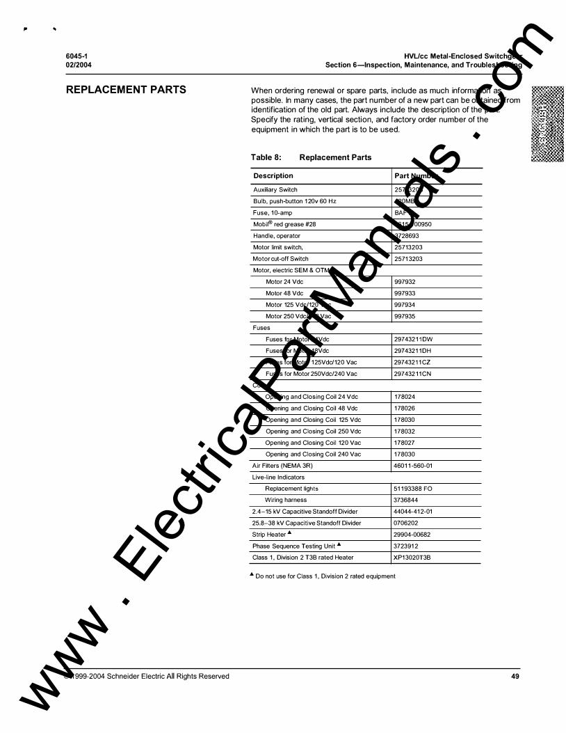
, ..
6045-1 02/2004
REPLACEMENT PARTS
© 1999-2004 Schneider Electric All Rights Reserved
HVL/cc Metal-Enclosed Switchgear Section 6-lnspection, Maintenance, and Troubleshooting
When ordering renewal or spare parts, include as much information as possible. In many cases, the part number of a new part can be obtained from identification of the old part. Always include the description of the part. Specify the rating, vertical section, and factory order number of the equipment in which the part is to be used.
Table 8: Replacement Parts
Description Part Number
Auxiliary Switch 25713203
Bulb, push-button 1 20v 60 Hz 120MB
Fuse, 10-amp BAF10
Mobil® red grease #28 161 5-1 00950
Handle, operator 3728693
Motor limit switch, 25713203
Motor cut-off Switch 2571 3203
Motor, electric SEM & OTM
Motor 24 Vdc 997932
Motor 48 Vdc 997933
Motor 125 Vdc/120 Vac 997934
Motor 250 Vdc/240 Vac 997935
Fuses
Fuses for Motor 24Vdc 2974321 1 DW
Fuses for Motor 48Vdc 2974321 1 DH
Fuses for Motor 125Vdc/120 Vac 2974321 1 CZ
Fuses for Motor 250Vdc/240 Vac 297432 1 1 CN
Coils
Opening and Closing Coil 24 Vdc 178024
Opening and Closing Coil 48 Vdc 1 78026
Opening and Closing Coil 125 Vdc 1 78030
Opening and Closing Coil 250 Vdc 1 78032
Opening and Closing Coil 120 Vac 1 78027
Opening and Closing Coil 240 Vac 1 78030
Air Filters (NEMA 3R) 4601 1 -560-01
Live-line Indicators
Replacement lights 51 1 93388 FO
Wiring harness 3736844
2.4-15 kV Capacitive Standoff Divider 44044-41 2-01
25.8-38 kV Capacitive Standoff Divider 0706202
Strip Heater "' 29904-00682
Phase Sequence Testing Unit "' 372391 2
Class 1 , Division 2 T3B rated Heater XP1 3020T3B
"' Do not use for Class 1 , Division 2 rated equipment
49
www . El
ectric
alPar
tMan
uals
. com
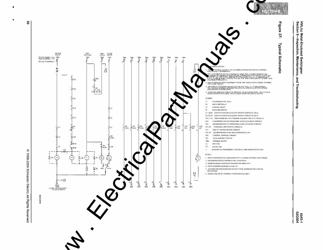
•
' C.l1 0
@ � <.o <.o <.o "' 0 0 -!:>
(/) () :::T :::J CD c: � m 1D u �-
� I :::T (j) :;o CD "' CD < CD CL
MOTOR VOLTS
DEVICE NAME - TBM ANSI TI::RMINAL - 5
DEVICE TEHMINAL- 1! �
. I * D6
· I
u €&10 TBM
CLOS<:: MOTOR & TRiP VOLTS CO�lM0�
� f:l �
521
510
514
513
Sl-5
Sf, >T-3
2A
TRIP DE:V;CES
TBM 9
13
TBM 8
BA
TRIP CLOSE '.'OlJS VOLTS
TBM TBM 9A 7
0
13/>J tJCZr�
" K1
K1
TBM 1 5 " TBM
1 3 TBM 51
13"
S5 l j Sil 1_l S€ ,\S/a * A,$1b T M�l;:�
"/, '"/, 146 16 1 4 52
THr TBM TBM
T8r;1 53
151
"/, "
S9 A...Sfb
TBM
TBM 55 D
17
'"6 5<l
S3 ASia
T8M
TBM ,, "
"6 58
S7 P.Sih
TBM
TBM
21
"6
S l 1 GSI
T8M
TBM
23
"/,
$12
GS!
TBM
TBM
25
"6
S18 SFI
TBM
27 I
TO
0
S18 B!'i
TBM
S19 B!'"'
OP[RATION Of' SWITCH
1 IHE SWnCHWILL CLOSE: i!- fHE CLOSING 6PRINGS HAVE BF.f.N (;HP..RGED ELECTRiCALLY OR MANUAU.Y.
-JAS CONT!NUITY WHEN THE CLOS!NG SPRINGS 1\RE IS OPEN MJD NO CONTINUOUS fR!P SiGNfol iS .�\PPLIED
jt[J.��§91��1;��·f{H�{���[��lH��J,Tl9}�9��fJ����AS/a E.
3. ASia CLOSING ALLOWS CONTINUITY IN THE TRIP CIRCUIT AS1b OPENS OPENING THE' CLOSE CiRCUIT
4 APPLYING !>. 1 RIP SiGNAL ENfH.G!Zi::S "I HE H�IP COIL Y1 !f D!SCHP..RGES THE OPEN�f'JG SPRINGS, OPENING THE SWiTCH WH[N THE S\.-'/ITCH OPENS AS/a AND AS:b CH.<\."lGE STP..TE.
5 SPAR!;: A.S/<1 AND AS!b CONTACTS !ND!CATE THE Bf-�EAKER STATE ASia CLOSES WHEN THE SWiTCH CLOSES ASib CLOSES W�lE'N THE $WITCH OPf::NS
U::GE:ND
f'" 1 CARl RIDGE F-USE:., Kt.M:� K1 ANTI-PUMP RELAY
K2 CONTROL RELAY
M CHAH.G!NG MOl OR
�1 . S3·S•"i SWITCH POSITION AUXILIA.RY SWITCH CONTACTS (AS! a)
S2, S?-Sfl SWITCH POSITION f,UXIUII.RY SWITCH CONfACfS (ASI�I
S 10.1 1 , 1 2 GROUNDING SY'/1 I"CH POSiTION AUXILIARY SWi I C H CON TII.C I S 513 LOAD BREAK SW!TCH OPERATING LEVCR ACTUATED CONTACT
S14
S15,16
GROUNDING SWITCH OPERATING LEVER ACTUII.lED CON f,\CT
�HARGING LIMIT SWITCH CON!"AGTS
£17 END or CHARGC MOTOR CONTACT
$18.19 Bl�"JWN.'MISSING FUSf: INDICATIONI;NTEP.L()CK
520 CONTROL DEPRt:SS CON !ACT 5.21 LOCK AUXILIARY .SWiTCH
TBM TE'RM!NAL BLOCK
Y1 TRiP COiL
Y2 CL03E COIL
AUXILI.A.RY BL�JWNiMISSIN�-; FliSE RELAY /INST/I.N"fANEOUS & TDE)
NOlES
i . SWITCH SHOV"\!N IN THE OPEN STATE W!fH CLOSING SPRINGS DiSCH�RGED
2. GROUNDING SWITCH SHOWN IN TH!: OPI::N SlATE
3 SOME TERMINAL POINTS NOT S�iOWN rOR SIMPLICITY
4 SWITCH WiRING DIAGR.'�M !5 44044-177
5 DESTINAI"!ON WIRE: MARKERS WllMOUf WIRE NUMBERS ARE USED IN MECHANISM
6 DIODES �.R£ ON DC CONTROL rOWER MODULE ONLY
., !C' c @ w
�
� 'C
c:;· e!.. en 0 ::J" CD 3 Cl -c:;·
(f) :r; (I) < !l c:: -· n g n a> S: I � - Ill ::J -� m (I) ::J n !:!. '!::!: 0 0 "' ::J (I) - a.
S: (f) �· � - n (I) ::J" ::> cc Ill (I) ::J Ill n .,
_<D Ill ::J a.
-1
a c: C' (5' "' ::J" 0
sa. ::r CQ
0 0'> � 0 "" -�=> O c.n o , -�=> �
www . El
ectric
alPar
tMan
uals
. com

6045-1 02/2004
CORRECTIVE MAINTENANCE
Medium Voltage Fuses
© 1999-2004 Schneider Electric All Rights Reserved
HVL/cc Metal-Enclosed Switchgear Section 6-lnspection, Maintenance, and Troubleshooting
This section contains information on how to perform corrective maintenance on HVL/cc Metal-Enclosed Switchgear.
Medium voltage fuses provide over-current protection for the medium-voltage switch as well as short circuit interrupting protection up to the short-circuit current rating of the equipment. Schneider Electric HVL!cc equipment can use only current-l imiting fuses manufactured by Schneider Electric or Bussmann.
C AU TION HAZARD OF EQUIPMENT DAMAGE
Do not substitute any other fuse.
Failure to follow this instruction can result in equipment damage.
Always follow the steps listed below before entering the fuse compartment to replace or perform maintenance on the fuses.
A DANG ER HAZARD OF ELECTRIC SHOCK, BURN, O R EXPLOSION.
• Turn off al l power supplying this equipment before working on or inside. • Always use a properly rated voltage sensing device to confirm that power
is off. • Beware of potential hazards, wear personal protective equipment and
take adequate safety precautions. • Replace all devices, doors, and covers before turning on the power to
this equipment.
Failure to follow these instructions will result in death or serious injury.
1 . To determine if a fuse has been blown, observe the blown fuse or liveline indicator.
NOTE: If the live line indicator is not illuminating properly refer to"Troubleshooting" on page 54 or replace the indicator if necessary.
2 . De-energ ize (turn off) the switch. Use a properly rated voltage sensing device to test and verify that the power is off. Padlock, and tag all upstream or downstream sources that could energize the primary fuses or control power to prevent inadvertent closure or energization .
3. Place the switch in the OPEN position . The load-side Llls should not be on. Close the ground for the switch i f so equipped (see Figure 18 on page 28, Figure 1 9 on page 29, and Figure 20 on page 30.
NOTE: Always replace all three fuses even if only one has blown to maintain system coordination. When one fuse blows the other two will have seen an over-current condition therefore are also damaged.
4. Replace the load-side panel . Verify that it is properly placed in the interlock slot and all hooks are engaged.
5. Open the ground switch first (if so equipped), then the main switch can be closed re-energizing the circuit.
51
www . El
ectric
alPar
tMan
uals
. com
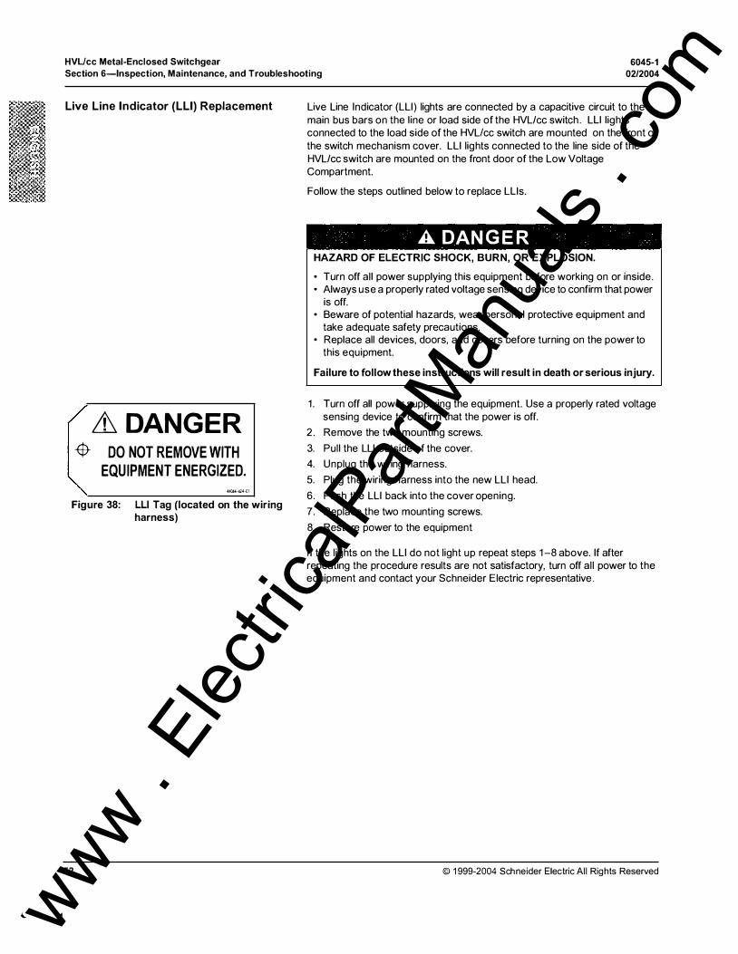
'- �
HVUcc Metal-Enclosed Switchgear
Section 6-lnspection, Maintenance, and Troubleshooting 6045-1
02/2004
Live Line Indicator (LLI) Replacement
� DANGER -$- DO NOT REMOVE WITH
EQUIPMENT ENERGIZED. #J44.-424--D1
Figure 38: LLI Tag (located on the wiring harness)
52
Live Line Indicator (LLI) lights are connected by a capacitive circuit to the main bus bars on the line or load side of the HVL/cc switch . Lll lights connected to the load side of the HVL!cc switch are mounted on the front of the switch mechanism cover. LLI lights connected to the line side of the HVL/cc switch are mounted on the front door of the Low Voltage Compartment.
Follow the steps outlined below to replace Llls.
A DANG ER HAZARD OF ELECTRIC SHOCK, BURN, OR EXPLOSION.
• Turn off all power supplying this equipment before working on or inside. • Always use a properly rated voltage sensing device to confirm that power
is off. • Beware of potential hazards, wear personal protective equipment and
take adequate safety precautions. • Replace all devices, doors, and covers before turning on the power to
this equipment.
Failure to follow these instructions will result in death or serious injury.
1. Turn off all power supplying the equipment. Use a properly rated voltage sensing device to confirm that the power is off.
2 . Remove the two mounting screws.
3. Pull the LLI outside of the cover.
4. Unplug the wiring harness.
5. Plug the wiring harness into the new LLI head.
6. Push the LLI back into the cover opening.
7. Replace the two mounting screws.
8. Restore power to the equipment
If the lights on the LLI do not light up repeat steps 1-8 above. If after repeating the procedure results are not satisfactory, turn off al l power to the equipment and contact your Schneider Electric representative.
© 1999-2004 Schneider Electric Al l Rights Reserved
www . El
ectric
alPar
tMan
uals
. com
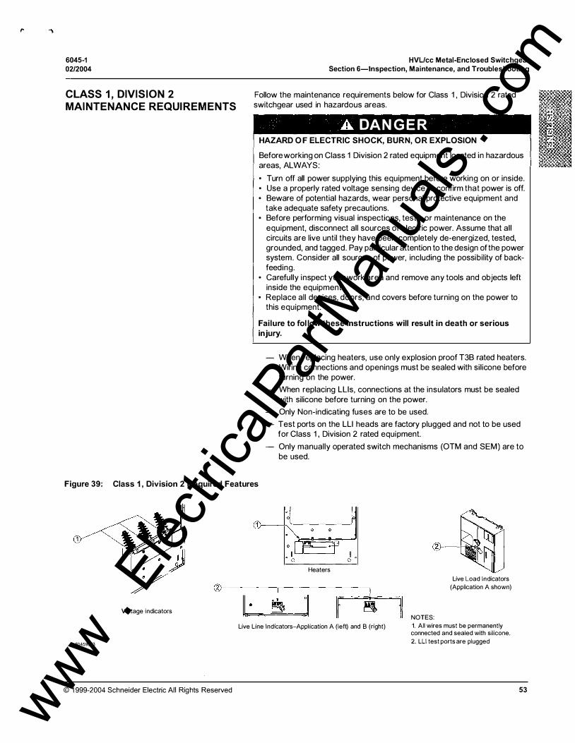
,.
6045-1 02/2004
CLASS 1, DIVISION 2 MAINTENANCE REQUIREMENTS
HVL/cc Metal-Enclosed Switchgear Section 6-lnspection, Maintenance, and Troubleshooting
Follow the maintenance requirements below for Class 1 , Division 2 rated switchgear used in hazardous areas.
A DANG ER HAZARD O F ELECTRIC SHOCK, BURN, OR EXPLOSION
Before working on Class 1 Division 2 rated equipment located in hazardous areas, ALWAYS:
• Turn off all power supplying this equipment before working on or inside. • Use a properly rated voltage sensing device to confirm that power is off. • Beware of potential hazards, wear personal protective equipment and
take adequate safety precautions. • Before performing visual inspections, tests, or maintenance on the
equipment, disconnect all sources of electric power. Assume that all circuits are live until they have been completely de-energized, tested, grounded, and tagged. Pay particular attention to the design of the power system. Consider all sources of power, including the possibil ity of backfeeding.
• Carefully inspect your work area and remove any tools and objects left inside the equipment.
• Replace all devices, doors, and covers before turning on the power to this equipment.
Failure to fol low these instructions will result in death or serious injury.
- When replacing heaters, use only explosion proof T3B rated heaters. Wiring connections and openings must be sealed with silicone before turning on the power.
- When replacing LLis, connections at the insulators must be sealed with silicone before turning on the power.
- Only Non-indicating fuses are to be used.
- Test ports on the LLI heads are factory plugged and not to be used for Class 1 , Division 2 rated equipment.
Only manually operated switch mechanisms (OTM and SEM ) are to be used.
Figure 39: Class 1 , Division 2 Required Features
H . 0
Heaters
@r---------,---------------.
� ,] r � Voltage indicators It· Live Line Indicators-Application A (left) and B (right)
60459023
© 1999-2004 Schneider Electric All Rights Reserved
'"il NOTES:
Live Load Indicators (Application A shown)
1. All wires must be permanently connected and sealed with silicone. 2. LLJ test ports are plugged
53 www . El
ectric
alPar
tMan
uals
. com

.... .)
HVUcc Metal-Enclosed Switchgear
Section 6-lnspection, Maintenance, and Troubleshooting 6045-1
02/2004
TROUBLESHOOTING
54
A .DAN G ER HAZARD OF ELECTRIC SHOCK, BURN,
OR EXPLOSION
• This equipment must be installed and serviced only by qualified personnel.
• Qualified persons performing diagnostics or troubleshooting that require electrical conductors to be energized must comply with NFPA 70 E - Standard for Electrical Safety Requirements for Employee Workplaces and OSHA Standards - 29 CFR Part 1 9 1 0 Subpart S - Electrical .
Failure t o fol low these instructions will result in death or serious injury.
The following tables list conditions, mechanisms, and solutions to problems that may occur in HVL/cc Metal-Enclosed Switchgear.
Table 9: Troubleshooting General Issues
Condition Mechanism
Live-line Indicator will not il luminate ALL
Load-side panel cannot be removed
or installed ALL
Ground switch cannot be operated ALL
Switch cannot be operated ALL
-
ACTION: I • Test for voltage using a properly I rated voltage sensing device on 2 1
of the test ports on the Live-line I indicators • Check that the switch is closed • Check the Live-line block is okay I • Check that the fuses are installed I • Check that the fuses are not blown
(blown fuse indicator in lexan cover if provided)
• Check that the incoming cables are live
• Check that switch is open and in the grounded position (if applicable)
• Check that the switch is open • Check if fuse/load-side panel is
properly installed
• Check that grounding switch is open
• Check if fuses are in�ijllled and not blown (Fuselogic )
• Check if fuse/load-side panel is properly installed - -
Table 1 0: Troubleshooting Mechanism Issues
Condition
Electrical operation impossible but manual operation is possible
Operation impossible following an electrical closing
Insertion of operating handle is impossible following electrical closing
Mechanism
ALL
SEM &
OTM (with motor)
SEM &
OTM (with motor)
ACTION:
• Check for loose connections • Check coil circuit • Check control fuses • Check electrical interlocks
Motor cutoff switch Main interrupter cutoff switch Open/Close microswitches
• Check grounding switch position and cutoff switch
• Check the configuration of the I
CIP1 subassembly (see Figure 5 and Figure 6) I
• Use the operating handle to apply torque in the closing I direction until the end position is reached, then check voltage supply to ensure adequate I power is available.
• Open switch using backup power I • Lock-out the electrical operating mechanism. Push the back of the 1 switch shaft in the closing direction using a large screwdriver to al low insertion of handle,
• Using a properly rated voltage sensing device, check voltage to ensure the correct power is being supplied to the motor.
© 1 999-2004 Schneider E lectric All Rights Reserved
www . El
ectric
alPar
tMan
uals
. com

6045-1 02/2004
Table 1 1 :
DATE
Maintenance Log
INITIALS
© 1999-2004 Schneider Electric All Rights Reserved
HVL!cc Metal-Enclosed Switchgear
Section 6-lnspection, Maintenance, and Troubleshooting
ACTION
55 www . El
ectric
alPar
tMan
uals
. com

Instruction Bulletin
HVUccTM Medium Voltage, Metal-Enclosed Switchgear
Schneider Electric
... ..,
330 Weakley Road Smyrna, TN 37167 U.S.A. 1 -888-SquareD (1 -888-778-2733) www.SquareD.com
Electrical equipment should be installed, operated, serviced, and maintained only by qualified personnel. No responsibility is assumed by Schneider Electric for any consequences arising out of the use of this material.
6045-1 © 1999-2004 Schneider Electric All Rights Reserved Replaces 6045-1 , dated 02/2003
02/2004
www . El
ectric
alPar
tMan
uals
. com