
HVDC Systems in India - USAID SARI/Energy Integration · Outline Introduction HVDC Systems...
45
HVDC Systems in India
Transcript of HVDC Systems in India - USAID SARI/Energy Integration · Outline Introduction HVDC Systems...

HVDC Systems in India
Outline
Introduction
HVDC Systems presently in operation
– Main Data/Salient Features
Upcoming Projects
Future Challenges

765kV/400kV lines: about 1,03,000 ckms
220kV lines: about 132,000 ckms
HVDC Bipole(±500kV): 7,500 ckms–3 nos.
HVDC Back-to-back: 7 nos. (3000MW)
FSC – 22 nos.; TCSC – 6 nos.
Transmission Network - Present

Inter-regional Capacity – 22,400MW
National Grid – Present
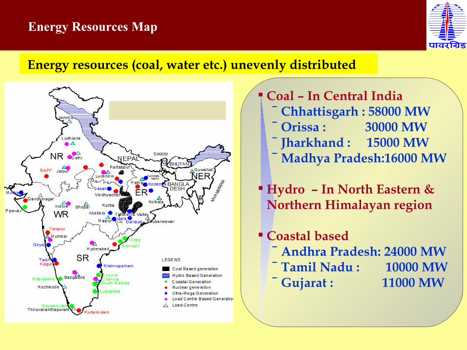
Coal – In Central India ‾ Chhattisgarh : 58000 MW‾ Orissa : 30000 MW‾ Jharkhand : 15000 MW‾ Madhya Pradesh:16000 MW
Hydro – In North Eastern & Northern Himalayan region
Coastal based‾ Andhra Pradesh: 24000 MW‾ Tamil Nadu : 10000 MW‾ Gujarat : 11000 MW
Energy resources (coal, water etc.) unevenly distributed
Energy Resources Map
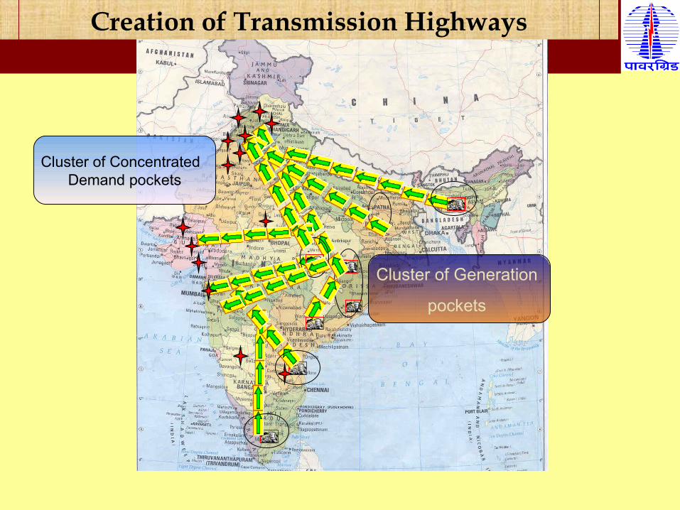
Creation of Transmission Highways
Cluster of Concentrated Demand pockets
Cluster of Generation
pockets
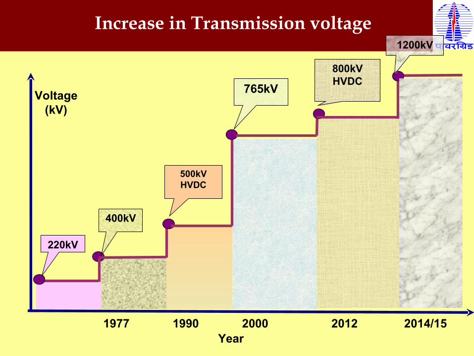
1977 1990 2000 2012 2014/15
Increase in Transmission voltage
Voltage (kV)
Year
220kV
400kV
500kVHVDC
765kV800kVHVDC
1200kV
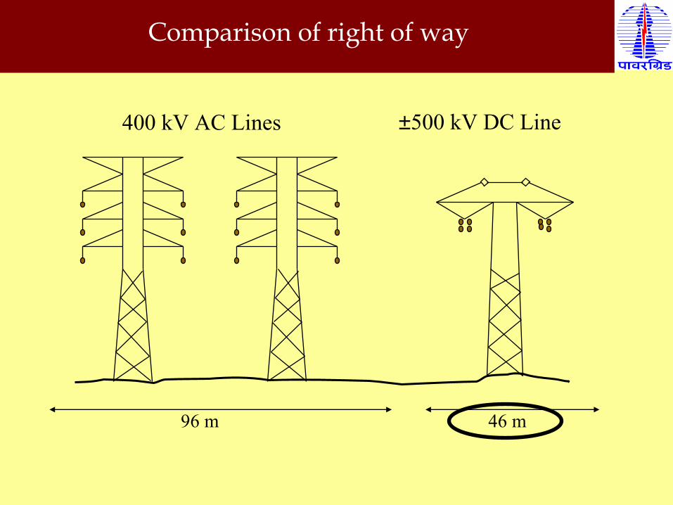
96 m 46 m
400 kV AC Lines ±500 kV DC Line
Comparison of right of way
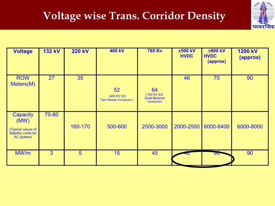
Voltage wise Trans. Corridor Density
Voltage 132 kV 220 kV 400 kV 765 Kv +500 kV HVDC
+800 kV HVDC
(approx)
1200 kV (approx)
ROW Meters(M)
27 35
52 (400 KV S/C
Twin Moose Conductor )
64( 765 KV S/C Quad Bersimis
conductor)
46 70 90
Capacity(MW)
(Typical values of Stability Limits for
AC system)
70-80
160-170
500-600
2500-3000
2000-2500
6000-6400
6000-8000
MW/m 3 5 15 45 48 90 90
Advantages of HVDC
Controlled Power Exchange Improve stability of AC system Transmission at Reduced Voltage Minimize power reduction in case of pole outage Benefits at low ambient temperature Asynchronous link

HVDC Systems presently in operation
(Main Data/Salient Features)

± 500 kV , 1500 MW Rihand – Dadri HVDC Project.
Main Data:Power rating : 1500MWNo. of Poles : 2AC Voltage : 400 kVDC Voltage : + 500 kV Converter Transformer-Rihand Terminal : 6 x 315 MVADadri Terminal : 6 x 305 MVALength of over head DC line: 816 KM.
Date of Commisioning: Dec-1991

±500kV,1500MW HVDC Bi-Pole Transmission link supplies Bulk Power from Thermal Power Plant of Rihand (Eastern part of Northern Grid) to Dadri (Western part of Northern Grid).
Each pole continuous power carrying capacity is 750 MW with 10% two hours overload and 33% five seconds overload capability .
Reverse power flow capability available.
During inclement weather condition power transmission is possible at ±400 kV DC voltage.
System Salient Features:
± 500 kV , 1500 MW Rihand – Dadri HVDC Project.

2 x 250 MW HVDC Vindhyachal Back to Back Station.
Completion date: April 1989
Main Data:(i) Power rating : 2 x 250 MW.(ii) No. of Blocks : 2(iii) AC Voltage : 400 kV(iv) DC Voltage : ± 70 kV (v) Converter Transformer : 8 x 156 MVA

System Salient Features:(i) It connects Vindhyachal Super Thermal Power Stations (Western
Region) to Singrauli Super Thermal Power Stations (Northern Region) in
Indian Grid.
(ii) Each Block power carrying capacity is 250 MW.
(iii) Bidirectional power flow capability is available.
(iv) The project achieve load diversity of Northern and Western region in Indian Grid
by meeting high demand from surplus power available in either regions
(v) First commercial Back to Back HVDC Station in India
2 x 250 MW HVDC Vindhyachal Back to Back Station.

2 x 500 MW HVDC Chandrapur Back to Back Station.
Start date: November 1993
Completion date: Dec 1997
Main Data:
Power rating : 2 x 500 MW.
No. of Blocks : 2
AC Voltage : 400 kV
DC Voltage : 205 kV
Converter Transformer : 12 x 234 MVA
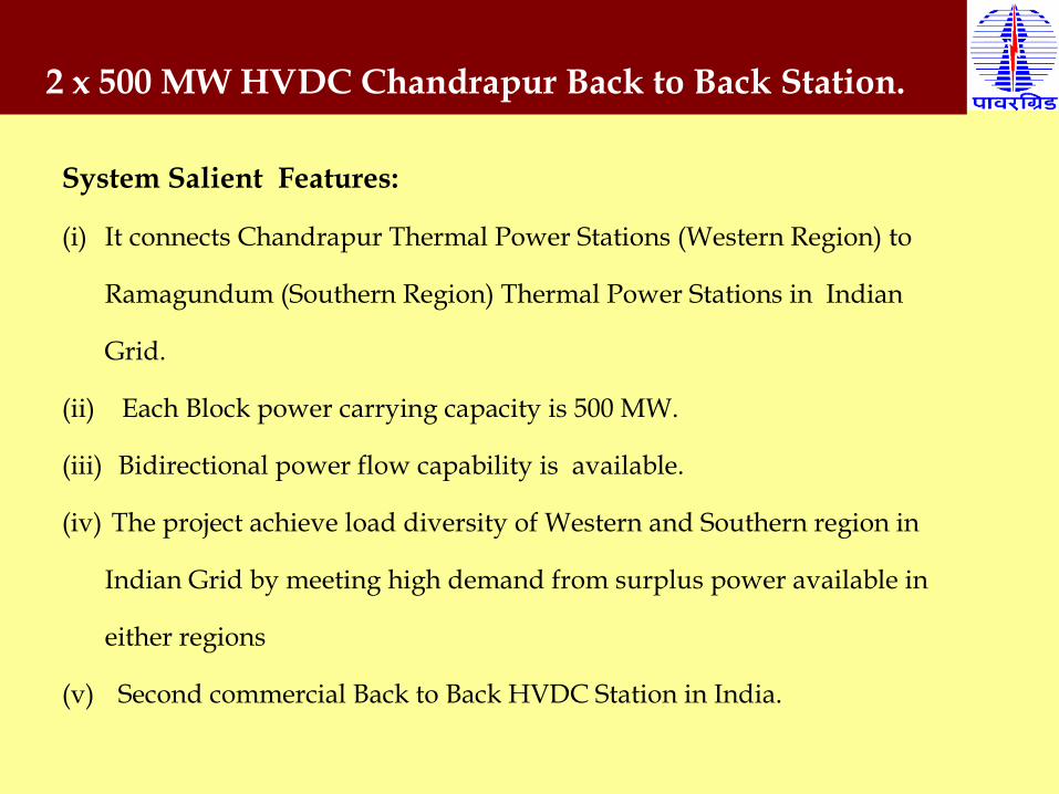
System Salient Features:
(i) It connects Chandrapur Thermal Power Stations (Western Region) to
Ramagundum (Southern Region) Thermal Power Stations in Indian
Grid.
(ii) Each Block power carrying capacity is 500 MW.
(iii) Bidirectional power flow capability is available.
(iv) The project achieve load diversity of Western and Southern region in
Indian Grid by meeting high demand from surplus power available in
either regions
(v) Second commercial Back to Back HVDC Station in India.
2 x 500 MW HVDC Chandrapur Back to Back Station.

+ 500 kV ,2000 MW, HVDC Talchar – Kolar Transmission Link
Completion date: June 2003
Main Data:Power rating : 2000 MW No. of Poles : 2AC Voltage : 400 kVDC Voltage : + 500 kV Converter Transformer-Talcher : 6 x 398 MVAKolar : 6 x 398 MVALength of over head DC line: 1369 KM.
This is the longest (1369 Km.) commercial HVDC link in India

HVDC Talchar – Kolar link was designed for 2000 MW continuous rating with inherent short term overload capacity depending on-
Ambient temperaturePrevailing voltages at Talcher and KolarCooling mechanism.
Further, DC Bipole lines with quad conductor was capable to transmit 1250 MW continuously with marginal incremental loss .
The inherent overload capability was utilized to meet the system contingencies by up gradation of Talcher – Kolar HVDC link capacity from 2000 MW to 2500 MW .
This enhanced capacity is to be used only under contingency and not for increasing HVDC Capacity for firm transfer of 2500 MW
Up gradation of + 500 kV HVDC Talchar – Kolar link from 2000 MW to 2500 MW
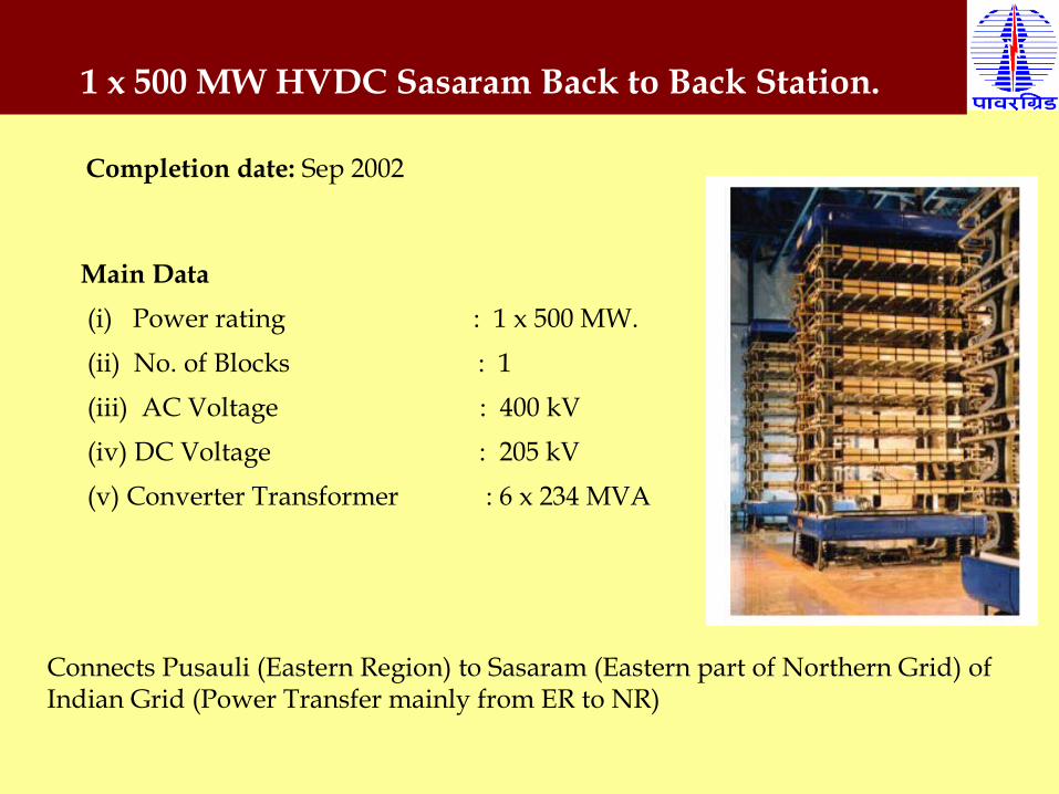
1 x 500 MW HVDC Sasaram Back to Back Station.
Completion date: Sep 2002
Main Data (i) Power rating : 1 x 500 MW. (ii) No. of Blocks : 1 (iii) AC Voltage : 400 kV (iv) DC Voltage : 205 kV (v) Converter Transformer : 6 x 234 MVA
Connects Pusauli (Eastern Region) to Sasaram (Eastern part of Northern Grid) of Indian Grid (Power Transfer mainly from ER to NR)
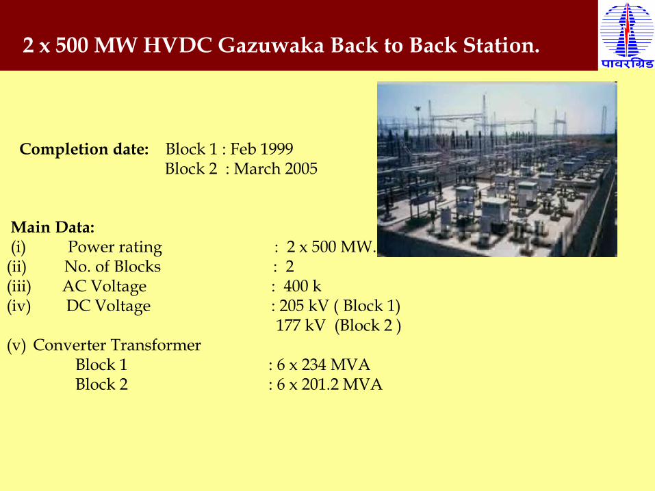
2 x 500 MW HVDC Gazuwaka Back to Back Station.
Completion date: Block 1 : Feb 1999 Block 2 : March 2005
Main Data: (i) Power rating : 2 x 500 MW.(ii) No. of Blocks : 2(iii) AC Voltage : 400 k(iv) DC Voltage : 205 kV ( Block 1) 177 kV (Block 2 )(v) Converter Transformer
Block 1 : 6 x 234 MVABlock 2 : 6 x 201.2 MVA

2 x 500 MW HVDC Gazuwaka Back to Back Station.
System Salient Feature
(i) It connects Jeypore (Eastern Region) to Gazuwaka (Southern Region)
Thermal Power Stations of Indian Grid
(ii) Each Block power carrying capacity is 500 MW.
(iii) Bidirectional power flow capability available.
(iv) The project achieve load diversity of Eastern and Southern region in Indian
Grid by meeting high demand from surplus power available

+ 500 kV, 2500 MW HVDC Ballia – Bhiwadi Transmission Link.
Pole 1 Commissioned on 31-03 10
Main Data:Power rating : 2500 MWNo. of Poles : 2AC Voltage : 400 kVDC Voltage : + 500 kV Length of over head DC line : 780 Km. Converter Transformer Ballia : 8 x 498 MVABhiwadi 8 x 498 MVA

(i) Bi-Pole + 500 kV, 2500 MW HVDC 780 km Transmission lines from Ballia (Eastern part of India) to Bhiwadi (Northern part of India) of Indian Grid.
(ii) Each pole power carrying capacity is 1250 MW. (iii) During unfavorable weather condition, operation at 70% to 80% DC voltage is possible. (iv) Reverse power flow capability is available.
+ 500 kV, 2500 MW HVDC Ballia – Bhiwadi Transmission Link
System Salient Features:

+ 500 kV, 2500 MW HVDC Ballia – Bhiwadi Transmission Link
Arrangement of Spare Converter
Transformer for quick restoration of
Pole in case of failure of Converter
Transformer.
Each Pole is having a dedicated Spare
Converter Transformer with
switching arrangement.
Transformer Configuration being
used for the first time.
Switchable Configuration of Spare Converter Transformer

Upcoming Projects
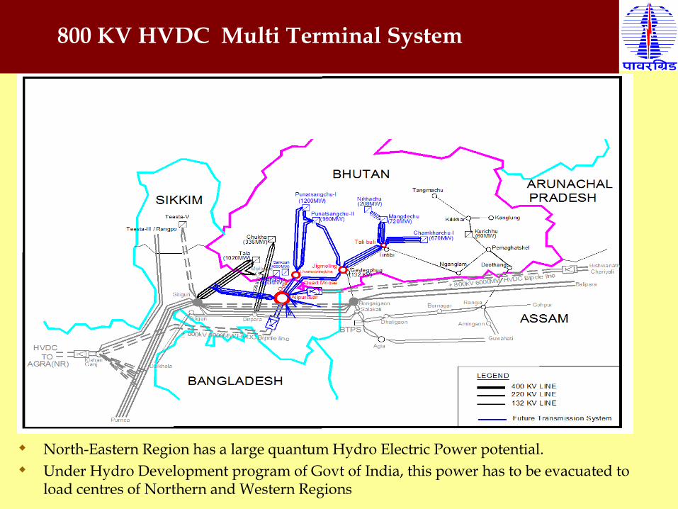
800 KV HVDC Multi Terminal System
North-Eastern Region has a large quantum Hydro Electric Power potential. Under Hydro Development program of Govt of India, this power has to be evacuated to
load centres of Northern and Western Regions

800 KV HVDC Multi Terminal System
POWERGRID is installing +/-800 kV, 6000 MW HVDC multi-terminal system of approx length of 1728 km from North Eastern Region to Agra
One Rectifier station in Biswanath Chariali (in North Eastern Region), second one in Alipurduar (in Eastern Region) and Inverter station at Agra (in Northern Region)

Converter stations at Biswanath Chariali and Alipurduar each handles a
power of 3000 MW and Converter station at Agra handles 6000 MW
power
This Tr. System originates from Assam and passes through West Bengal,
Bihar and terminates in Uttar Pradesh
First Multi Terminal project in India
800 KV HVDC Multi Terminal System

400 KV AlipurduarBiswanath Ch. to Alipurduar
800 KV HVDC Multi Terminal System

First ±800 KV Multi-Terminal HVDC project in the world.
First 12 pulse 800 KV terminal of the world
First Multi-Terminal with continuous 33% overload feature
After considering the continuous 33% overload feature, this will be the highest capacity HVDC project of the world.
Each pole of the Multi-terminal shall be designed for 2000 MW which is the highest capacity poles in the world.
The Earth electrode shall be designed for 5000 A DC continuous current which shall be 1st of its kind in the world.
Salient features of 800 KV multi-terminal HVDC project
HVDC Multi terminal System- Advantages
•Create power pooling points to collect power from Several Generating
Stations and to transport it on ± 800 kV DC bipolar lines (power highway) to
major Load Centers located far away
•Efficient Utilization of ± 800 kV Line by connecting parallel HVDC
Converters physically at different locations ( eg Rectifiers 450 km apart) to the
same.
• 33 % Continuous Overload Capability gives higher availability for Nominal
Power Transmission -(For North East –Agra Multi terminal)

1 X 500 MW India Bangladesh Interconnector project
1 X 500 MW India Bangladesh Interconnector project
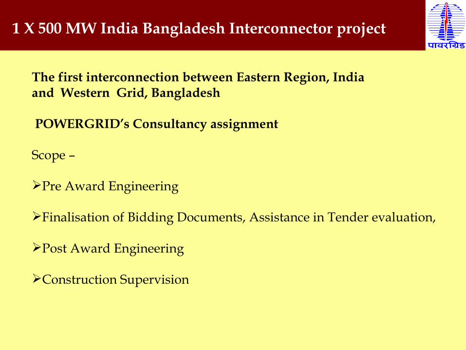
The first interconnection between Eastern Region, India and Western Grid, Bangladesh
POWERGRID’s Consultancy assignment
Scope –
Pre Award Engineering
Finalisation of Bidding Documents, Assistance in Tender evaluation,
Post Award Engineering
Construction Supervision

185 Kms
90 Kms
150 Kms
Proposed Route for Interconnection
Madurai
Rameshwaram
Anuradhapura
Talaimannar
India – Sri Lanka Interconnection
Indo-Srilanka HVDC Inter Connecter Link
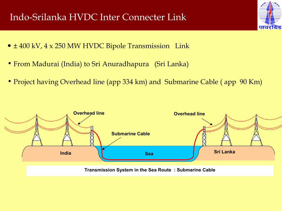
• ± 400 kV, 4 x 250 MW HVDC Bipole Transmission Link
• From Madurai (India) to Sri Anuradhapura (Sri Lanka)
• Project having Overhead line (app 334 km) and Submarine Cable ( app 90 Km)
India Sri LankaSea
Submarine Cable
Overhead line Overhead line
Transmission System in the Sea Route : Submarine Cable
Champa- Kurukshetra ± 800 KV , 3000 MW HVDC Link IPP generation projects coming up in Chhattisgarh for transfer of
power to different target regions viz. Western and Northern region.
Above generation projects are mainly coming up in Raigarh (near Kotra), Champa-Janjgir and Raigarh (Near Tamnar) complex.
Based on the transmission system requirement for transfer of power to Northern Region from these generation projects , following WR – NR interconnector for IPP Projects in Chhattisgarh is proposed :-
Establishment of 3000MW 800KV HVDC Bipole Terminal Station each at Champa Pooling Station (WR) and Kurukshetra (NR) respectively (provision to upgrade the terminals at 6000MW at a later date).
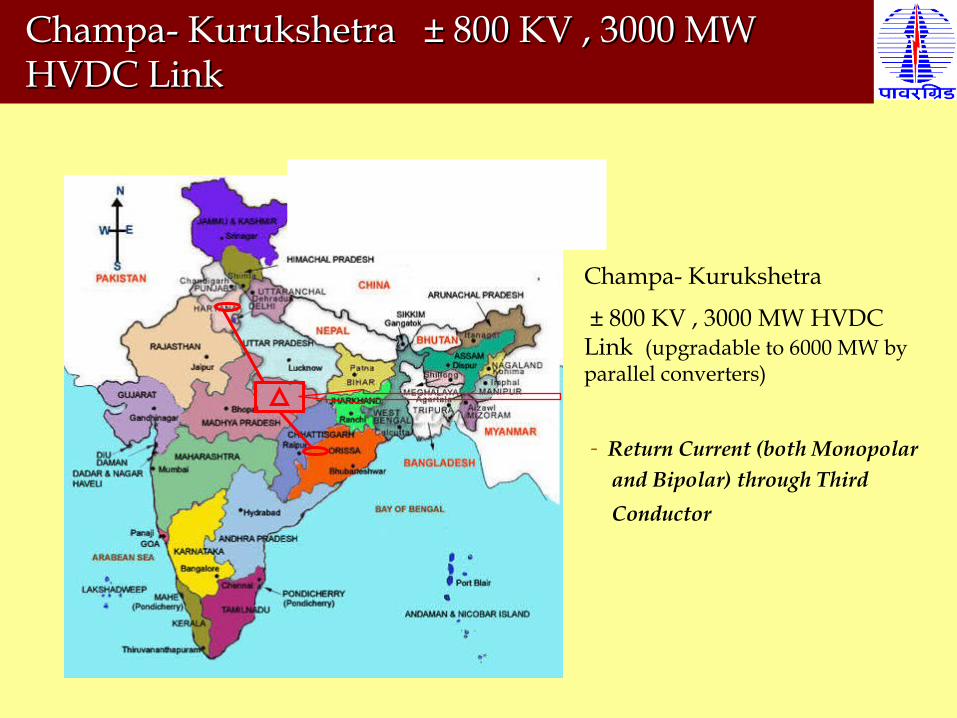
Champa- Kurukshetra
± 800 KV , 3000 MW HVDC Link (upgradable to 6000 MW by parallel converters)
- Return Current (both Monopolar and Bipolar) through Third Conductor
Champa- Kurukshetra ± 800 KV , 3000 MW Champa- Kurukshetra ± 800 KV , 3000 MW HVDC Link HVDC Link

Advantages of having Third Conductor for Return path:
It eliminates the element of uncertainty about the proper functionality
of the earth electrode station.
It shall avoid acquisition of separate land for each earth electrode stations,
construction of electrode stations which involves requirement
of large amount of steel rods and coke.
The construction of new Transmission Line between Earth Electrode
Station and respective HVDC terminal station shall be avoided.

Future Challenges
Transmission growth driven by
Strong GDP growth – requiring massive expansion of Power Sector
Uneven distribution of energy resources
Change in generation profile
Growth Drivers

100152
218
437
323
2007 2012 2017 2022 2027Year
GW
Peak Demand
132220
306
575
425
2007 2012 2017 2022 2027Year
GW
73 GW
101 GW119 GW
150 GWInstalled Capacity Requirement
End of X plan
During 12th plan
During 13th plan
During 11th plan
205
Future Power Scenario
Need of new initiatives in Transmission
Need of long distance Transmission system
Minimum use of land and Right-of-Way
Optimal cost per MW transmission
Optimal Transmission Losses
HVDC Technology….
One of the Solution….