![[O] cOmpaniessavarinocompanies.com/content/documents/bids... · hvac general notes hvac abbreviations hvac ductwork symbols hvac control symbols chaintreuil jensen stark architectural](https://static.fdocuments.in/doc/165x107/5ae5a13f7f8b9a29048c7dfa/o-compan-general-notes-hvac-abbreviations-hvac-ductwork-symbols-hvac-control-symbols.jpg)
Hvac
12
Heating Ventilation and Air Conditioning (HVAC)
-
Upload
atia-khursheed -
Category
Documents
-
view
29 -
download
0
description
Intelligent buildings and their hvac system
Transcript of Hvac
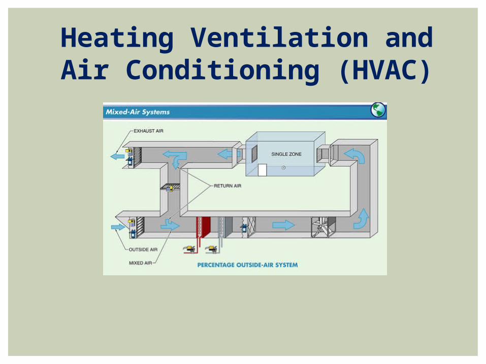
Heating Ventilation and Air Conditioning (HVAC)

Heating Ventilation and Air Conditioning (HVAC)HVAC (heating, ventilation, and air conditioning) is the technology of indoor and vehicular environmental comfort. HVAC system design is a sub discipline of mechanical engineering, based on the principles of thermodynamics, fluid mechanics, and heat transfer.Comfort requirements that are typically impacted by the HVAC system include:• Temperature• Humidity• Air movement• Fresh air• Clean air• Noise levels• Lighting• Furniture and work surfacesThere are five primary loops that can describe virtually any type of HVAC system.

Cooling load

• In a cooling tower, the warm water returning from the condenser is sprayed over the fill inside the tower while a propeller fan draws outdoor air upward through the fill.
• One common type of fill consists of several thin, closely spaced layers of plastic or wood.
• The water spreads over the surface of the fill to increase the contact with the passing air.
Cooling Tower
Water tank
softner
Cooling tower

• The movement of air through the fill allows heat to transfer from the water to the air.
• This causes some of the water to evaporate, a process that cools the remaining water.
• The remaining cooled water then falls to the tower sump and is returned to the condenser.
Cooling Tower
Perforated layers

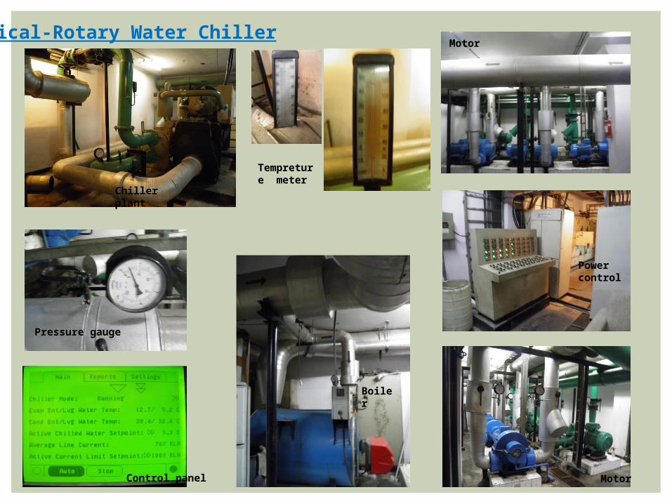
Helical-Rotary Water Chiller
• the refrigeration loop is a packaged, helical-rotary (screw) water chiller.• This example chiller uses an evaporator to produce chilled water by
transferring heat from the water to the liquid refrigerant. • The compressor consists of two screw-like rotors to compress the
refrigerant vapor, raising its pressure and temperature.• A second heat exchanger serves as the water-cooled condenser, where
refrigerant is condensed inside the• shell and water flows through the tubes.
evaporator
compressor
condenser
Chilled water
Helical-Rotary Water Chiller
Control panel
Boiler
Power control
Motor
Chiller plant
Motor
Tempreture meter
Pressure gauge
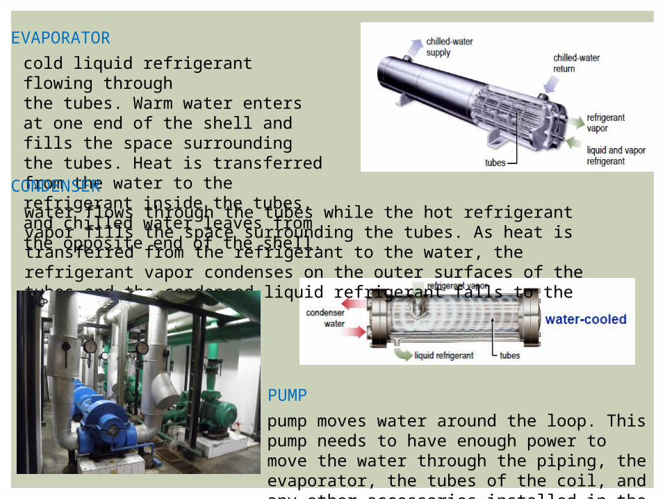
cold liquid refrigerant flowing throughthe tubes. Warm water enters at one end of the shell and fills the space surrounding the tubes. Heat is transferred from the water to the refrigerant inside the tubes, and chilled water leaves from the opposite end of the shell.
CONDENSER
EVAPORATOR
water flows through the tubes while the hot refrigerant vapor fills the space surrounding the tubes. As heat is transferred from the refrigerant to the water, the refrigerant vapor condenses on the outer surfaces of the tubes and the condensed liquid refrigerant falls to the bottom of the shell.
pump moves water around the loop. This pump needs to have enough power to move the water through the piping, the evaporator, the tubes of the coil, and any other accessories installed in the chilled-water loop.
PUMP

The chilled-water loop responds to changing cooling loads by varying either the temperature or the quantity of water delivered to the cooling coil. The most common method, however, is to vary the quantity of water flowing through the cooling coil by using a control valve. As the cooling load decreases, the modulating control valve reduces the rate of chilled-water flow through the coil, decreasing its cooling capacity.
CONTROL VALVE
The supply air must be cold enough to absorb excess sensible heat from the space and dry enough to absorb excess moisture (latent heat). Heat exchanger, commonly known as a cooling coil, is often used to cool and dehumidify the supply air before it is delivered to the space.
COOLING COIL

AHU(air handling unit)An air handler, or air handling unit (often abbreviated to AHU), is a device used to condition and circulate air as part of a heating, ventilating, and air-conditioning (HVAC) system. An air handler is usually a large metal box containing a blower, heating or cooling elements, filter racks or chambers, sound attenuators, and dampers. Air handlers usually connect to a ductwork ventilation system that distributes the conditioned air through the building and returns it to the AHU. An air handler designed for outdoor use, typically on roofs, is known as a packaged unit (PU) or rooftop unit (RTU).
OUTDOOR AIR INLET
INDOOR AIR INLET
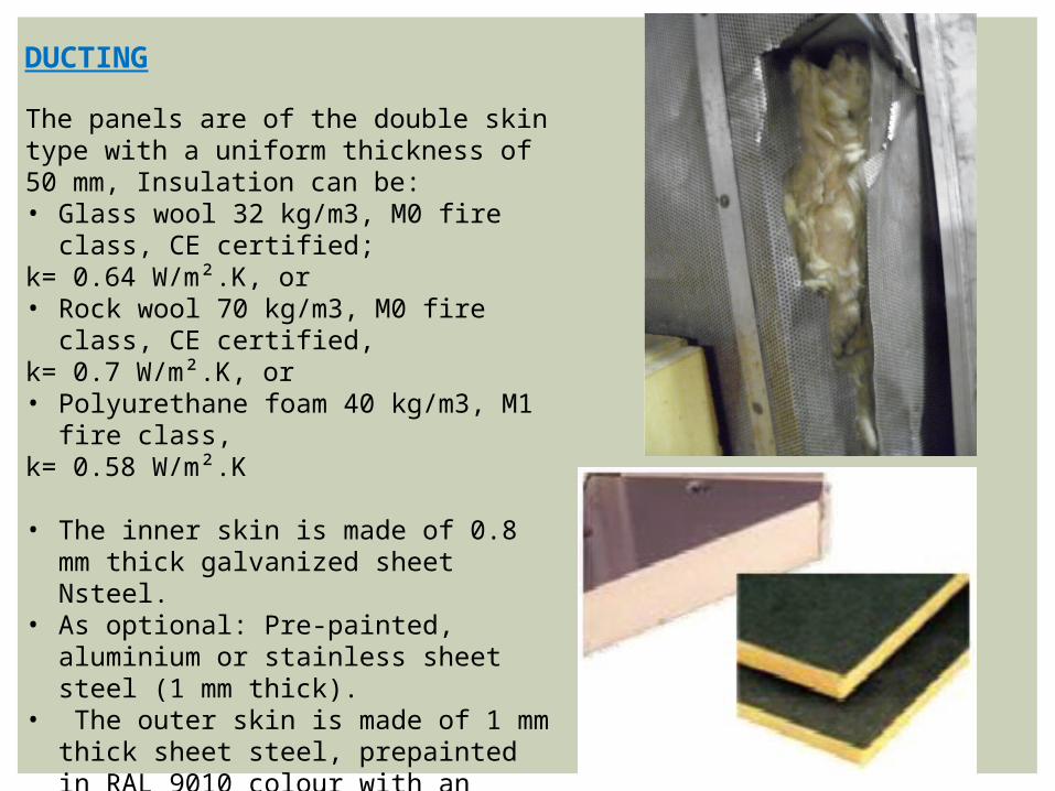
The panels are of the double skin type with a uniform thickness of 50 mm, Insulation can be: • Glass wool 32 kg/m3, M0 fire class,
CE certified;k= 0.64 W/m².K, or • Rock wool 70 kg/m3, M0 fire class,
CE certified,k= 0.7 W/m².K, or • Polyurethane foam 40 kg/m3, M1 fire
class, k= 0.58 W/m².K
• The inner skin is made of 0.8 mm thick galvanized sheet Nsteel.
• As optional: Pre-painted, aluminium or stainless sheet steel (1 mm thick).
• The outer skin is made of 1 mm thick sheet steel, prepainted in RAL 9010 colour with an epoxy primer undercoat and a 25 micron thick polyester topcoat (resistance to salt spray test = 750 hours).
• The panels are fastened to each other by means of screws countersunk in the panels (absence of localized thermal bridges). The screws are equipped with panel-coloured plastic caps.
DUCTING
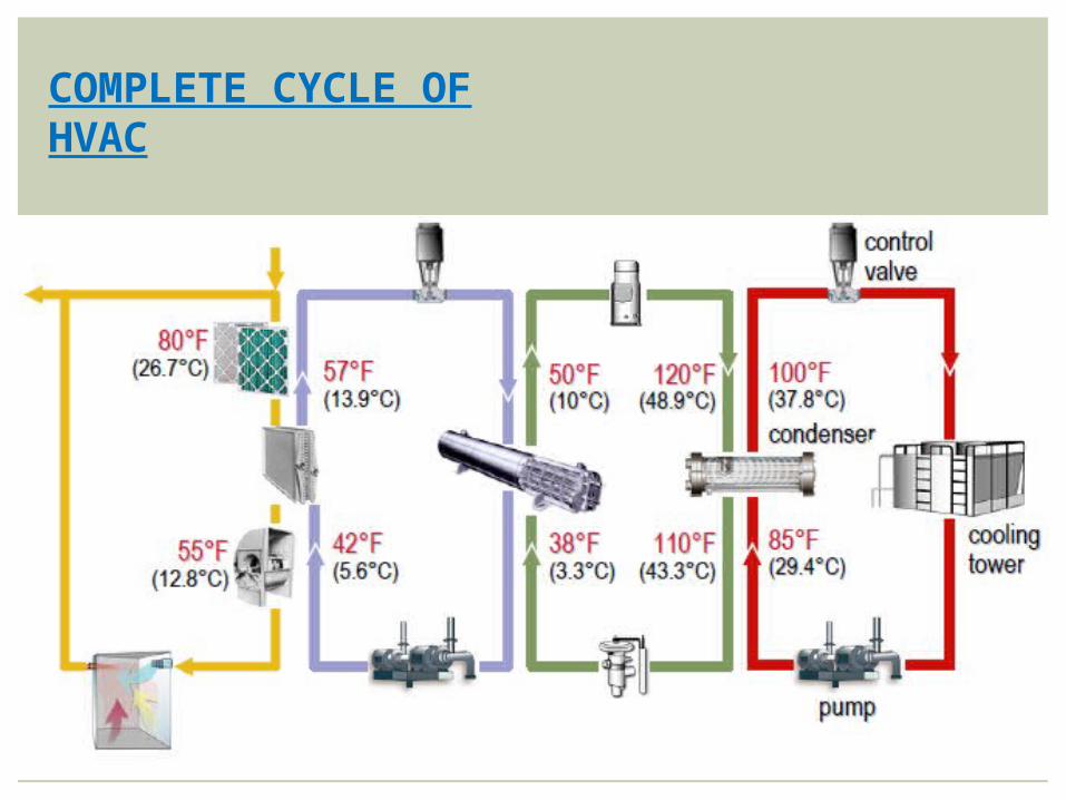
COMPLETE CYCLE OF HVAC