HVAC Control & Balancing Dampers - … · 6 ® Pressure Drop Data Pressure Drop Comparison...
20
1 HVAC Control & Balancing Dampers Models VCD, ICD, FBH, FBV, MBD and RBD • Selection • Construction • Performance January 2018
Transcript of HVAC Control & Balancing Dampers - … · 6 ® Pressure Drop Data Pressure Drop Comparison...

1
HVAC Control & Balancing Dampers
Models VCD, ICD, FBH, FBV, MBD and RBD
• Selection • Construction • Performance
January2018
2
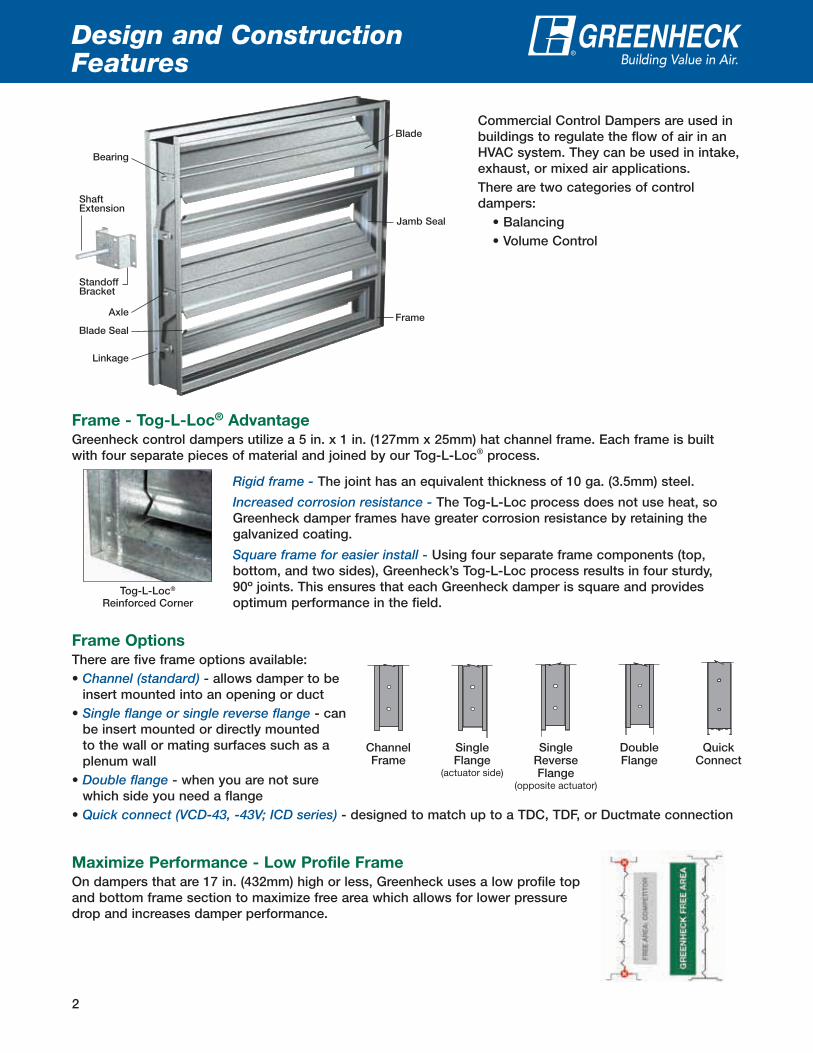
Design and Construction Features
Axle
Bearing
Blade
Frame
Linkage
Jamb Seal
Blade Seal
StandoffBracket
ShaftExtension
®
Frame Options
There are five frame options available:• Channel (standard) - allows damper to be
insert mounted into an opening or duct• Single flange or single reverse flange - can
be insert mounted or directly mounted to the wall or mating surfaces such as a plenum wall
• Double flange - when you are not sure which side you need a flange
• Quick connect (VCD-43, -43V; ICD series) - designed to match up to a TDC, TDF, or Ductmate connection
ChannelFrame
DoubleFlange
QuickConnect
SingleFlange
(actuator side)
SingleReverseFlange
(opposite actuator)
Commercial Control Dampers are used in buildings to regulate the flow of air in an HVAC system. They can be used in intake, exhaust, or mixed air applications.There are two categories of control dampers:
• Balancing• Volume Control
Maximize Performance - Low Profile Frame
On dampers that are 17 in. (432mm) high or less, Greenheck uses a low profile top and bottom frame section to maximize free area which allows for lower pressure drop and increases damper performance.
Tog-L-Loc®
Reinforced Corner
Frame - Tog-L-Loc® Advantage
Greenheck control dampers utilize a 5 in. x 1 in. (127mm x 25mm) hat channel frame. Each frame is built with four separate pieces of material and joined by our Tog-L-Loc® process.
Rigid frame - The joint has an equivalent thickness of 10 ga. (3.5mm) steel.
Increased corrosion resistance - The Tog-L-Loc process does not use heat, so Greenheck damper frames have greater corrosion resistance by retaining the galvanized coating.
Square frame for easier install - Using four separate frame components (top, bottom, and two sides), Greenheck’s Tog-L-Loc process results in four sturdy, 90º joints. This ensures that each Greenheck damper is square and provides optimum performance in the field.
3
Design and Construction Features
®
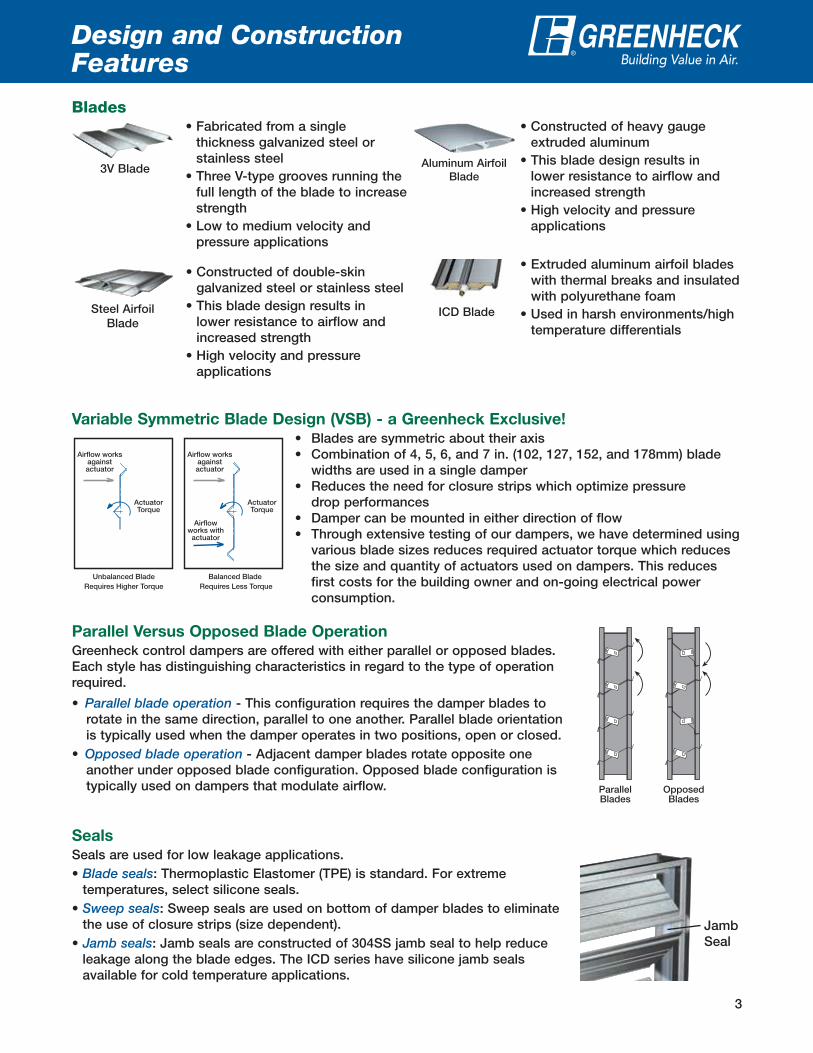
Blades
3V Blade
• Fabricated from a single thickness galvanized steel or stainless steel
• Three V-type grooves running the full length of the blade to increase strength
• Low to medium velocity and pressure applications
Steel Airfoil Blade
• Constructed of double-skin galvanized steel or stainless steel
• This blade design results in lower resistance to airflow and increased strength
• High velocity and pressure applications
Aluminum Airfoil Blade
• Constructed of heavy gauge extruded aluminum
• This blade design results in lower resistance to airflow and increased strength
• High velocity and pressure applications
ICD Blade
• Extruded aluminum airfoil blades with thermal breaks and insulated with polyurethane foam
• Used in harsh environments/high temperature differentials
Variable Symmetric Blade Design (VSB) - a Greenheck Exclusive!
• Blades are symmetric about their axis • Combination of 4, 5, 6, and 7 in. (102, 127, 152, and 178mm) blade widths are used in a single damper • Reduces the need for closure strips which optimize pressure drop performances • Damper can be mounted in either direction of flow • Through extensive testing of our dampers, we have determined using
various blade sizes reduces required actuator torque which reduces the size and quantity of actuators used on dampers. This reduces first costs for the building owner and on-going electrical power consumption.
ActuatorTorque
ActuatorTorque
Airflow worksagainstactuator
Airflow worksagainstactuator
Airflowworks with
actuator
Unbalanced BladeRequires Higher Torque
Balanced Blade Requires Less Torque
ParallelBlades
OpposedBlades
Parallel Versus Opposed Blade Operation
Greenheck control dampers are offered with either parallel or opposed blades. Each style has distinguishing characteristics in regard to the type of operation required.
• Parallel blade operation - This configuration requires the damper blades to rotate in the same direction, parallel to one another. Parallel blade orientation is typically used when the damper operates in two positions, open or closed.
• Opposed blade operation - Adjacent damper blades rotate opposite one another under opposed blade configuration. Opposed blade configuration is typically used on dampers that modulate airflow.
Seals
Seals are used for low leakage applications.• Blade seals: Thermoplastic Elastomer (TPE) is standard. For extreme
temperatures, select silicone seals.• Sweep seals: Sweep seals are used on bottom of damper blades to eliminate
the use of closure strips (size dependent).• Jamb seals: Jamb seals are constructed of 304SS jamb seal to help reduce
leakage along the blade edges. The ICD series have silicone jamb seals available for cold temperature applications.
Jamb Seal
4
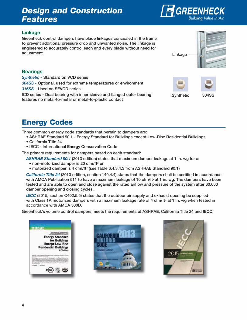
Linkage
Greenheck control dampers have blade linkages concealed in the frame to prevent additional pressure drop and unwanted noise. The linkage is engineered to accurately control each and every blade without need for adjustment.
Bearings
Synthetic - Standard on VCD series304SS - Optional, used for extreme temperatures or environment316SS - Used on SEVCD seriesICD series - Dual bearing with inner sleeve and flanged outer bearing features no metal-to-metal or metal-to-plastic contact
Design and Construction Features
®
Linkage
Synthetic 304SS
Energy CodesThree common energy code standards that pertain to dampers are:
• ASHRAE Standard 90.1 - Energy Standard for Buildings except Low-Rise Residential Buildings • California Title 24 • IECC - International Energy Conservation Code
The primary requirements for dampers based on each standard: ASHRAE Standard 90.1 (2013 edition) states that maximum damper leakage at 1 in. wg for a:
• non-motorized damper is 20 cfm/ft2 or • motorized damper is 4 cfm/ft2 (see Table 6.4.3.4.3 from ASHRAE Standard 90.1)
California Title 24 (2013 edition, section 140.4.4) states that the dampers shall be certified in accordance with AMCA Publication 511 to have a maximum leakage of 10 cfm/ft2 at 1 in. wg. The dampers have been tested and are able to open and close against the rated airflow and pressure of the system after 60,000 damper opening and closing cycles.
IECC (2015, section C402.5.5) states that the outdoor air supply and exhaust opening be supplied with Class 1A motorized dampers with a maximum leakage rate of 4 cfm/ft2 at 1 in. wg when tested in accordance with AMCA 500D.
Greenheck’s volume control dampers meets the requirements of ASHRAE, California Title 24 and IECC.

5
Air LeakagePerformance ®
VCD-33, 34 SEVCD-33 Leakage Class*
Maximum Damper Width
1 in. wg (0.25 kPa)
4 in. wg(1 kPa)
8 in. wg(2 kPa)
10 in. wg(2.5 kPa)
60 in. (1524mm) 1A 1 1 1
TorqueData is based on a torque of 7.0 in-lb/ft² (0.79 N·m) applied to close and seat the damper during the test.
Air leakage is based on operation between 32° and 120°F (0 and 49°C).Tested for leakage in accordance with ANSI/AMCA Standard 500-D, Figure 5.5.Tested for air performance in accordance with ANSI/AMCA Standard 500-D, Figures 5.2, 5.3 and 5.5.
TorqueData is based on a torque of 5.0 in-lb/ft² (0.56 N·m) applied to close and seat the damper during the test.
VCD-23, SEVCD-23 Leakage Class*
Maximum Damper Width
1 in. wg (0.25 kPa)
4 in. wg(1 kPa)
5 in. wg(1.2 kPa)
48 in. (1219mm) 1A 1 1
VCD-43 Leakage Class*
Maximum Damper Width
1 in. wg (0.25 kPa)
4 in. wg(1 kPa)
8 in. wg(2 kPa)
10 in. wg(2.5 kPa)
60 in. (1524mm) 1A 1 1 1
*Leakage Class DefinitionsThe maximum allowable leakage is defined by AMCA as the following:
• Leakage Class 1A - 3 cfm/ft2 @ 1 in. wg (Class 1A is only defined at 1 in. wg).• Leakage Class 1 - 4 cfm/ft2 @ 1 in. wg - 8 cfm/ft2 @ 4 in. wg - 11 cfm/ft2 @ 8 in. wg - 12.6 cfm/ft2 @ 10 in. wg
Maximum Leakagecfm/sq. ft. (cmh/sq.m)
ModelPressure
@ 1 in. wg(0.25 kPa)
@ 4 in. wg(1 kPa)
VCD-23V, 43V Class 1A Class 1
VCD-40 Class 1A Class 1
VCD-33, 42, 42V Class 1A Class 1
VCDR-53 Class 1 Class 1
VCDRM-53 Class 1 Class 1
ICD-44, 45 Leakage Class*
Maximum Damper Width
1 in. wg (0.25 kPa)
4 in. wg(1 kPa)
8 in. wg(2 kPa)
10 in. wg(2.5 kPa)
48 in. (1219mm) 1A 1 1 1
TorqueData is based on a torque of 9.0 in-lb/ft² (1.02 N·m) applied to close and seat the damper during the test.
6
®
Pressure Drop Data
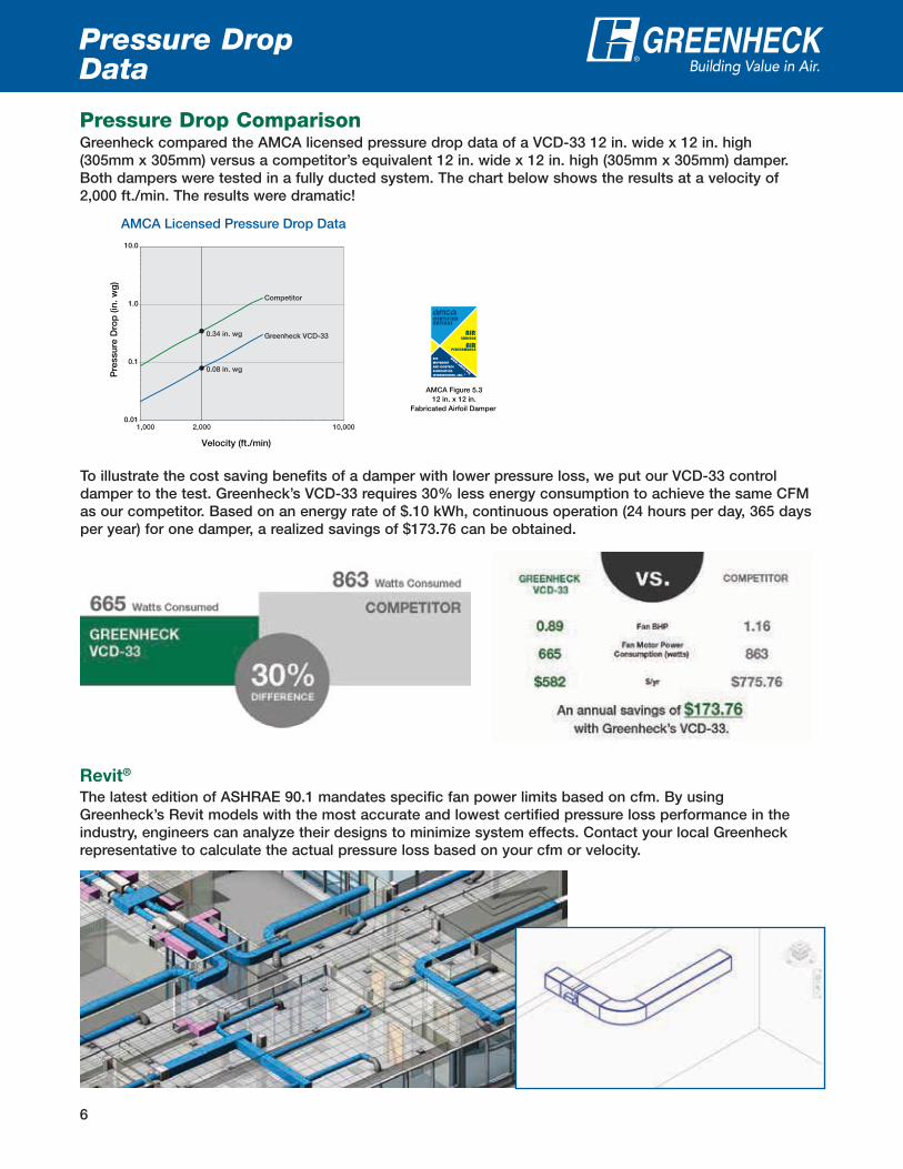
Pressure Drop ComparisonGreenheck compared the AMCA licensed pressure drop data of a VCD-33 12 in. wide x 12 in. high (305mm x 305mm) versus a competitor’s equivalent 12 in. wide x 12 in. high (305mm x 305mm) damper. Both dampers were tested in a fully ducted system. The chart below shows the results at a velocity of 2,000 ft./min. The results were dramatic!
0.01
0.1
1.0
10.0
Pre
ssur
e D
rop
(in.
wg
)
Velocity (ft./min)
AMCA Licensed Pressure Drop Data
AMCA Figure 5.312 in. x 12 in.
Fabricated Airfoil Damper
Competitor
Greenheck VCD-33
0.08 in. wg
0.34 in. wg
1,000 2,000 10,000
To illustrate the cost saving benefits of a damper with lower pressure loss, we put our VCD-33 control damper to the test. Greenheck’s VCD-33 requires 30% less energy consumption to achieve the same CFM as our competitor. Based on an energy rate of $.10 kWh, continuous operation (24 hours per day, 365 days per year) for one damper, a realized savings of $173.76 can be obtained.
Revit®
The latest edition of ASHRAE 90.1 mandates specific fan power limits based on cfm. By using Greenheck’s Revit models with the most accurate and lowest certified pressure loss performance in the industry, engineers can analyze their designs to minimize system effects. Contact your local Greenheck representative to calculate the actual pressure loss based on your cfm or velocity.

7
®
Pressure Drop Performance
Pressure drop testing was conducted in accordance with AMCA Standard 500-D using the three configurations shown. All data has been corrected to represent standard air at a density of .075 lb/ft3 (1.2 kg/m3).
Actual pressure drop found in an HVAC system is a combination of many factors. This pressure drop information, along with an analysis of other system influences should be used to estimate actual pressure losses for a damper installed in an HVAC system.
Figure 5.3 Illustrates a fully ducted damper. This configuration has the lowest pressure drop of the three test configurations because entrance and exit losses are minimized by straight duct runs upstream and downstream of the damper.
Figure 5.2 Illustrates a ducted damper exhausting air into an open area. This configuration has a lower pressure drop than Figure 5.5 because entrance losses are minimized by a straight duct run upstream of the damper.
Figure 5.5 Illustrates a plenum mounted damper. This configuration has the highest pressure drop because of high entrance and exit losses due to the sudden changes of area in the system.
5D 6D
Figure 5.3
Figure 5.2
5D
Figure 5.5
4 (W) (H)D=3.14
D = Duct lengthW = Damper widthH = Damper height
Greenheck Fan Corporation certifies that the model VCD-23, 33, 34, 43, SEVCD-23 and 33 shown herein are licensed to bear the AMCA Seal. The ratings shown are based on tests and procedures performed in accordance with AMCA Publication 511 and comply with the requirements of the AMCA Certified Ratings Programs. The AMCA Certified Ratings Seal applies to Air Leakage and Air Performance ratings.
Greenheck Fan Corporation certifies that the model VCD-20 and VCD-40 shown herein are licensed to bear the AMCA Seal. The ratings shown are based on tests and procedures performed in accordance with AMCA Publication 511 and comply with the requirements of the AMCA Certified Ratings Programs. The AMCA Certified Ratings Seal applies to Air Performance ratings only.
Greenheck Fan Corporation certifies that the model ICD-44 and ICD-45 shown herein are licensed to bear the AMCA Seal. The ratings shown are based on tests and procedures performed in accordance with AMCA Publication 511 and comply with the requirements of the AMCA Certified Ratings Programs. The AMCA Certified Ratings Seal applies to Air Leakage, Air Performance and Energy Efficiency ratings.
8
®
Dimensioninches
12 24
AMCA figure 5.2 5.3 5.5 5.2 5.3 5.5
Velocity (ft/min.)
Pressure Drop in. wg
500 .01 .01 .02 .01 .01 .02
1000 .06 .02 .10 .04 .01 .09
1500 .13 .05 .22 .08 .03 .20
2000 .23 .08 .38 .15 .06 .36
2500 .37 .13 .60 .23 .09 .56
3000 .53 .19 .86 .33 .13 .81
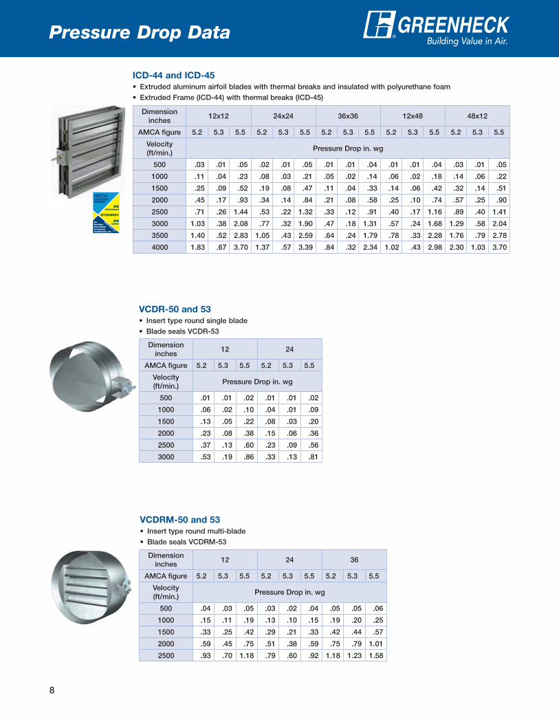
VCDR-50 and 53
• Insert type round single blade
• Blade seals VCDR-53
Dimensioninches
12 24 36
AMCA figure 5.2 5.3 5.5 5.2 5.3 5.5 5.2 5.3 5.5
Velocity (ft/min.)
Pressure Drop in. wg
500 .04 .03 .05 .03 .02 .04 .05 .05 .06
1000 .15 .11 .19 .13 .10 .15 .19 .20 .25
1500 .33 .25 .42 .29 .21 .33 .42 .44 .57
2000 .59 .45 .75 .51 .38 .59 .75 .79 1.01
2500 .93 .70 1.18 .79 .60 .92 1.18 1.23 1.58
VCDRM-50 and 53
• Insert type round multi-blade
• Blade seals VCDRM-53
Dimensioninches
12x12 24x24 36x36 12x48 48x12
AMCA figure 5.2 5.3 5.5 5.2 5.3 5.5 5.2 5.3 5.5 5.2 5.3 5.5 5.2 5.3 5.5
Velocity (ft/min.)
Pressure Drop in. wg
500 .03 .01 .05 .02 .01 .05 .01 .01 .04 .01 .01 .04 .03 .01 .05
1000 .11 .04 .23 .08 .03 .21 .05 .02 .14 .06 .02 .18 .14 .06 .22
1500 .25 .09 .52 .19 .08 .47 .11 .04 .33 .14 .06 .42 .32 .14 .51
2000 .45 .17 .93 .34 .14 .84 .21 .08 .58 .25 .10 .74 .57 .25 .90
2500 .71 .26 1.44 .53 .22 1.32 .33 .12 .91 .40 .17 1.16 .89 .40 1.41
3000 1.03 .38 2.08 .77 .32 1.90 .47 .18 1.31 .57 .24 1.68 1.29 .58 2.04
3500 1.40 .52 2.83 1.05 .43 2.59 .64 .24 1.79 .78 .33 2.28 1.76 .79 2.78
4000 1.83 .67 3.70 1.37 .57 3.39 .84 .32 2.34 1.02 .43 2.98 2.30 1.03 3.70
ICD-44 and ICD-45
• Extruded aluminum airfoil blades with thermal breaks and insulated with polyurethane foam
• Extruded Frame (ICD-44) with thermal breaks (ICD-45)
Pressure Drop Data
9
®
Dimensioninches
12x12 24x24 36x36 12x48 48x12
AMCA figure 5.2 5.3 5.5 5.2 5.3 5.5 5.2 5.3 5.5 5.2 5.3 5.5 5.2 5.3 5.5
Velocity (ft/min.)
Pressure Drop in. wg
500 .01 .01 .03 .01 .01 .03 .01 .01 .03 .01 .01 .03 .01 .01 .03
1000 .05 .03 .13 .03 .02 .12 .02 .02 .12 .04 .03 .12 .03 .03 .12
1500 .11 .08 .30 .06 .04 .26 .05 .03 .28 .08 .07 .27 .07 .06 .28
2000 .19 .13 .53 .10 .07 .47 .09 .06 .50 .15 .12 .47 .12 .10 .49
2500 .29 .20 .82 .16 .11 .75 .14 .09 .78 .22 .18 .75 .18 .16 .77
3000 .41 .29 1.19 .23 .16 1.04 .19 .13 1.12 .32 .26 1.07 .26 .22 1.12
3500 .55 .40 1.62 .30 .21 1.41 .27 .19 1.53 .43 .36 1.45 .36 .30 1.53
4000 .72 .51 2.10 .40 .28 1.90 .35 .25 2.00 .56 .46 1.91 .47 .39 2.01
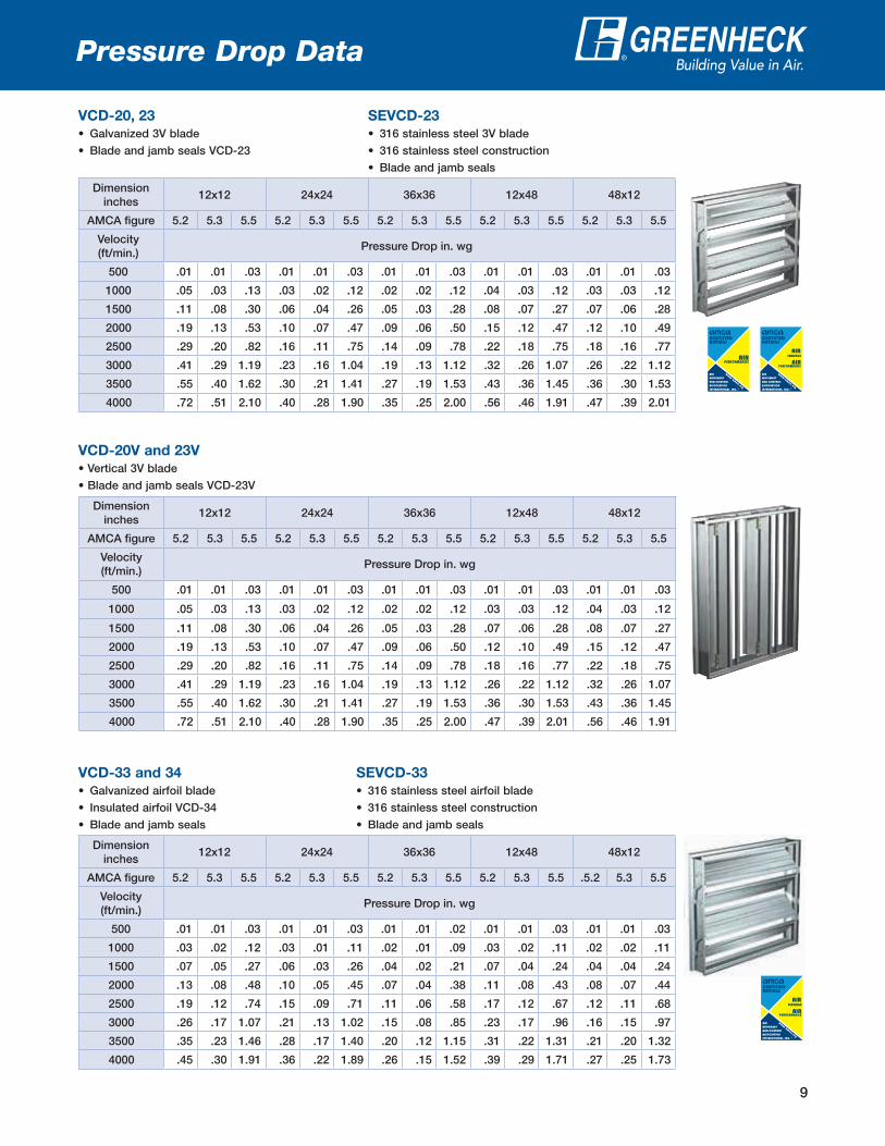
VCD-20, 23
• Galvanized 3V blade
• Blade and jamb seals VCD-23
SEVCD-23
• 316 stainless steel 3V blade
• 316 stainless steel construction
• Blade and jamb seals
Dimensioninches
12x12 24x24 36x36 12x48 48x12
AMCA figure 5.2 5.3 5.5 5.2 5.3 5.5 5.2 5.3 5.5 5.2 5.3 5.5 5.2 5.3 5.5
Velocity (ft/min.)
Pressure Drop in. wg
500 .01 .01 .03 .01 .01 .03 .01 .01 .03 .01 .01 .03 .01 .01 .03
1000 .05 .03 .13 .03 .02 .12 .02 .02 .12 .03 .03 .12 .04 .03 .12
1500 .11 .08 .30 .06 .04 .26 .05 .03 .28 .07 .06 .28 .08 .07 .27
2000 .19 .13 .53 .10 .07 .47 .09 .06 .50 .12 .10 .49 .15 .12 .47
2500 .29 .20 .82 .16 .11 .75 .14 .09 .78 .18 .16 .77 .22 .18 .75
3000 .41 .29 1.19 .23 .16 1.04 .19 .13 1.12 .26 .22 1.12 .32 .26 1.07
3500 .55 .40 1.62 .30 .21 1.41 .27 .19 1.53 .36 .30 1.53 .43 .36 1.45
4000 .72 .51 2.10 .40 .28 1.90 .35 .25 2.00 .47 .39 2.01 .56 .46 1.91
VCD-20V and 23V
• Vertical 3V blade
• Blade and jamb seals VCD-23V
Dimensioninches
12x12 24x24 36x36 12x48 48x12
AMCA figure 5.2 5.3 5.5 5.2 5.3 5.5 5.2 5.3 5.5 5.2 5.3 5.5 .5.2 5.3 5.5
Velocity (ft/min.)
Pressure Drop in. wg
500 .01 .01 .03 .01 .01 .03 .01 .01 .02 .01 .01 .03 .01 .01 .03
1000 .03 .02 .12 .03 .01 .11 .02 .01 .09 .03 .02 .11 .02 .02 .11
1500 .07 .05 .27 .06 .03 .26 .04 .02 .21 .07 .04 .24 .04 .04 .24
2000 .13 .08 .48 .10 .05 .45 .07 .04 .38 .11 .08 .43 .08 .07 .44
2500 .19 .12 .74 .15 .09 .71 .11 .06 .58 .17 .12 .67 .12 .11 .68
3000 .26 .17 1.07 .21 .13 1.02 .15 .08 .85 .23 .17 .96 .16 .15 .97
3500 .35 .23 1.46 .28 .17 1.40 .20 .12 1.15 .31 .22 1.31 .21 .20 1.32
4000 .45 .30 1.91 .36 .22 1.89 .26 .15 1.52 .39 .29 1.71 .27 .25 1.73
VCD-33 and 34
• Galvanized airfoil blade
• Insulated airfoil VCD-34
• Blade and jamb seals
SEVCD-33
• 316 stainless steel airfoil blade
• 316 stainless steel construction
• Blade and jamb seals
Pressure Drop Data

10
Pressure Drop Data ®
Dimensioninches
12x12 24x24 36x36 12x48 48x12
AMCA figure 5.2 5.3 5.5 5.2 5.3 5.5 5.2 5.3 5.5 5.2 5.3 5.5 5.2 5.3 5.5
Velocity (ft/min.)
Pressure Drop in. wg
500 .01 .01 .03 .01 .01 .03 .01 .01 .02 .01 .01 .03 .01 .01 .03
1000 .03 .02 .12 .03 .01 .11 .02 .01 .09 .02 .02 .11 .03 .02 .11
1500 .07 .05 .27 .06 .03 .26 .04 .02 .21 .04 .04 .24 .07 .04 .24
2000 .13 .08 .48 .10 .05 .45 .07 .04 .38 .08 .07 .44 .11 .08 .43
2500 .19 .12 .74 .15 .09 .71 .11 .06 .58 .12 .11 .68 .17 .12 .67
3000 .26 .17 1.07 .21 .13 1.02 .15 .08 .85 .16 .15 .97 .23 .17 .96
3500 .35 .23 1.46 .28 .17 1.40 .20 .12 1.15 .21 .20 1.32 .31 .22 1.31
4000 .45 .30 1.91 .36 .22 1.89 .26 .15 1.52 .27 .25 1.73 .39 .29 1.71
VCD-33V
• Vertical galvanized airfoil blade
• Blade and jamb seals
Dimensioninches
12x12 24x24 36x36 12x48 48x12
AMCA figure 5.2 5.3 5.5 5.2 5.3 5.5 5.2 5.3 5.5 5.2 5.3 5.5 5.2 5.3 5.5
Velocity (ft/min.)
Pressure Drop in. wg
500 .08 .05 .10 .01 .01 .03 .01 .01 .03 .01 .01 .03 .06 .03 .08
1000 .31 .20 .40 .05 .02 .12 .04 .02 .11 .05 .03 .12 .23 .13 .29
1500 .69 .45 .88 .11 .05 .29 .09 .04 .26 .11 .07 .27 .52 .29 .63
2000 1.19 .76 1.54 .19 .10 .52 .16 .07 .46 .20 .12 .49 .91 .51 1.12
2500 1.84 1.19 2.41 .30 .15 .80 .24 .10 .72 .30 .19 .76 1.43 .81 1.76
3000 2.67 1.70 3.45 .43 .22 1.14 .35 .15 1.04 .43 .26 1.11 2.05 1.16 2.52
3500 3.59 2.29 4.75 .58 .30 1.60 .48 .20 1.43 .59 .36 1.53 2.82 1.59 3.40
4000 4.64 2.97 6.09 .76 .40 2.14 .62 .27 1.87 .77 .46 2.00 3.69 2.09 4.52
VCD-40
• Extruded aluminum airfoil blade
• Blades contained within the frame
• Blade and jamb seals
Dimensioninches
12x12 24x24 36x36 12x48 48x12
AMCA figure 5.2 5.3 5.5 5.2 5.3 5.5 5.2 5.3 5.5 5.2 5.3 5.5 5.2 5.3 5.5
Velocity (ft/min.)
Pressure Drop in. wg
500 .05 .03 .07 .01 .01 .04 .01 .01 .02 .01 .01 .03 .03 .02 .05
1000 .18 .12 .28 .05 .03 .17 .04 .02 .12 .01 .04 .18 .11 .06 .19
1500 .43 .28 .62 .12 .06 .37 .09 .05 .28 .14 .09 .40 .25 .14 .44
2000 .76 .49 1.11 .22 .11 .66 .17 .08 .50 .25 .16 .72 .44 .25 .78
2500 1.19 .77 1.73 .34 .17 1.04 .26 .13 .78 .39 .25 1.12 .69 .39 1.21
3000 1.71 1.11 2.50 .49 .24 1.50 .38 .19 1.13 .57 .36 1.62 1.0 .57 1.75
3500 2.33 1.51 3.41 .66 .33 2.04 .51 .26 1.53 .77 .49 2.21 1.36 .77 2.38
4000 3.04 1.98 4.45 .87 .43 2.66 .67 .34 2.01 1.01 .64 2.88 1.78 1.01 3.11
VCD-42
• Extruded aluminum airfoil blade
• Galvanized frame
• Blade and jamb seals

11
Pressure Drop Data ®
Dimensioninches
12x12 24x24 36x36 12x48 48x12
AMCA figure 5.2 5.3 5.5 5.2 5.3 5.5 5.2 5.3 5.5 5.2 5.3 5.5 5.2 5.3 5.5
Velocity (ft/min.)
Pressure Drop in. wg
500 .01 .01 .04 .01 .01 .03 .01 .01 .03 .01 .01 .03 .01 .01 .03
1000 .06 .03 .14 .04 .02 .12 .03 .01 .10 .06 .03 .11 .03 .02 .11
1500 .13 .07 .31 .10 .04 .27 .06 .02 .22 .13 .06 .25 .06 .04 .26
2000 .23 .14 .55 .18 .08 .48 .12 .04 .39 .23 .11 .46 .10 .08 .46
2500 .35 .21 .86 .28 .13 .75 .18 .06 .61 .36 .17 .72 .16 .12 .72
3000 .50 .29 1.23 .40 .19 1.07 .26 .09 .87 .51 .25 1.05 .23 .18 1.02
3500 .68 .39 1.67 .54 .26 1.47 .35 .13 1.19 .71 .34 1.43 .30 .24 1.40
4000 .88 .51 2.19 .70 .34 1.91 .46 .17 1.56 .93 .45 1.87 .39 .31 1.83
VCD-43
• Extruded aluminum airfoil blade
• Aluminum frame
• Blade and jamb seals
Dimensioninches
12x12 24x24 36x36 12x48 48x12
AMCA figure 5.2 5.3 5.5 5.2 5.3 5.5 5.2 5.3 5.5 5.2 5.3 5.5 5.2 5.3 5.5
Velocity (ft/min.)
Pressure Drop in. wg
500 .05 .03 .07 .01 .01 .04 .01 .01 .02 .03 .02 .05 .01 .01 .03
1000 .18 .12 .28 .05 .03 .17 .04 .02 .12 .11 .06 .19 .01 .04 .18
1500 .43 .28 .62 .12 .06 .37 .09 .05 .28 .25 .14 .44 .14 .09 .40
2000 .76 .49 1.11 .22 .11 .66 .17 .08 .50 .44 .25 .78 .25 .16 .72
2500 1.19 .77 1.73 .34 .17 1.04 .26 .13 .78 .69 .39 1.21 .39 .25 1.12
3000 1.71 1.11 2.50 .49 .24 1.50 .38 .19 1.13 1.0 .57 1.75 .57 .36 1.62
3500 2.33 1.51 3.41 .66 .33 2.04 .51 .26 1.53 1.36 .77 2.38 .77 .49 2.21
4000 3.04 1.98 4.45 .87 .43 2.66 .67 .34 2.01 1.78 1.01 3.11 1.04 .64 2.88
VCD-42V
• Vertical extruded aluminum airfoil blade
• Galvanized frame
• Blade and jamb seals
VCD-43V
• Vertical extruded aluminum airfoil blade
• Aluminum frame
• Blade and jamb seals
Dimensioninches
12x12 24x24 36x36 12x48 48x12
AMCA figure 5.2 5.3 5.5 5.2 5.3 5.5 5.2 5.3 5.5 5.2 5.3 5.5 5.2 5.3 5.5
Velocity (ft/min.)
Pressure Drop in. wg
500 .01 .01 .04 .01 .01 .03 .01 .01 .03 .01 .01 .03 .01 .01 .03
1000 .06 .03 .14 .04 .02 .12 .03 .01 .10 .03 .02 .11 .06 .03 .11
1500 .13 .07 .31 .10 .04 .27 .06 .02 .22 .06 .04 .26 .13 .06 .25
2000 .23 .14 .55 .18 .08 .48 .12 .04 .39 .10 .08 .46 .23 .11 .46
2500 .35 .21 .86 .28 .13 .75 .18 .06 .61 .16 .12 .72 .36 .17 .72
3000 .50 .29 1.23 .40 .19 1.07 .26 .09 .87 .23 .18 1.02 .51 .25 1.02
3500 .68 .39 1.67 .54 .26 1.47 .35 .13 1.19 .30 .24 1.40 .71 .34 1.40
4000 .88 .51 2.19 .70 .34 1.91 .46 .17 1.56 .39 .31 1.83 .93 .45 1.83

12
®
Options and Accessories
Open Close Indicator - OCIThe OCI provides positive open and closed signals when used in conjunction with remote indicator lights. Switches are physically linked to a damper blade and therefore give a true representation of the damper’s position.
ADamperLocation
L
CL Damper Frame
Sleeve
Damper D*
D* + 2 in. sq.
Factory Sleeve Option
Greenheck control dampers are available with factory furnished sleeves in lengths up to 48 in. (1219mm). When dampers are installed in factory sleeves, the “A” dimension specifies the location of damper within the sleeve.
Transitions
Greenheck control dampers can be supplied with the appropriate transition option in applications where dampers require installation in round or oval openings. The sleeve is transitioned at each end to the appropriate round, oval, or rectangular size.
Transition options available
Type O Type R Type C
Security Bars
When security becomes an issue, Greenheck offers optional factory-installed security bars. Security bars are factory welded into a 10 ga. (3.5mm) sleeve.
Paint Finishes
A wide variety of paint finishes are available including:• Anodize • Industrial Epoxy • Baked Enamel • Kynar®/Hylar®
• Epoxy • Hi-Pro PolyesterSee color charts on www.greenheck.com for standard color offering.
QR Codes
Greenheck has added QR (Quick Response) codes to the labels on commercial control and air measuring dampers.
When you scan the QR code with your smartphone, it will link to www.greenheck.com based on the model.
13
®
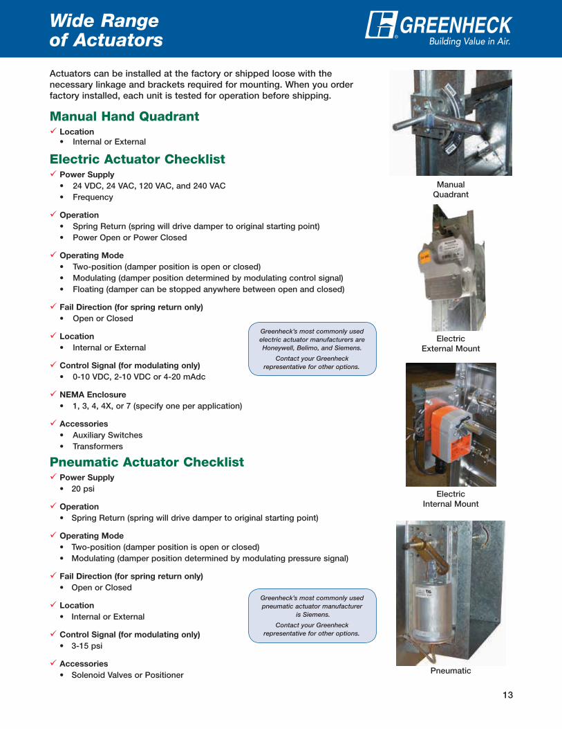
Wide Range of Actuators
Pneumatic
Pneumatic Actuator Checklist Power Supply
• 20 psi
Operation
• Spring Return (spring will drive damper to original starting point)
Operating Mode
• Two-position (damper position is open or closed) • Modulating (damper position determined by modulating pressure signal)
Fail Direction (for spring return only)
• Open or Closed
Location
• Internal or External
Control Signal (for modulating only)
• 3-15 psi
Accessories
• Solenoid Valves or Positioner
Manual Quadrant
Manual Hand Quadrant Location
• Internal or External
Electric Actuator Checklist Power Supply
• 24 VDC, 24 VAC, 120 VAC, and 240 VAC • Frequency
Operation
• Spring Return (spring will drive damper to original starting point) • Power Open or Power Closed
Operating Mode
• Two-position (damper position is open or closed) • Modulating (damper position determined by modulating control signal) • Floating (damper can be stopped anywhere between open and closed)
Fail Direction (for spring return only)
• Open or Closed
Location
• Internal or External
Control Signal (for modulating only)
• 0-10 VDC, 2-10 VDC or 4-20 mAdc
NEMA Enclosure
• 1, 3, 4, 4X, or 7 (specify one per application)
Accessories
• Auxiliary Switches • Transformers
Electric External Mount
Electric Internal Mount
Greenheck’s most commonly used electric actuator manufacturers are Honeywell, Belimo, and Siemens.
Contact your Greenheck representative for other options.
Greenheck’s most commonly used pneumatic actuator manufacturer
is Siemens.
Contact your Greenheck representative for other options.
Actuators can be installed at the factory or shipped loose with the necessary linkage and brackets required for mounting. When you order factory installed, each unit is tested for operation before shipping.

14
Volume Control Dampers Quick Selection Chart
X = StandardO = Optional VCD-20 VCD-20V VCD-23 VCD-23V VCD-33 VCD-33V VCD-34 VCD-34V VCD-40
Blad
e Pr
ofile
Single Blade
3V X X
3V-Vertical Blade X X
Airfoil X X
Airfoil-Vertical Blade X
Airfoil-Insulated X
Airfoil - Insulated Vertical Blade
X
Fram
e M
ater
ial Galvanized X X X X X X X X
304 Stainless Steel O O O O O O O O
Aluminum X
Blad
eM
ater
ial
Galvanized X X X X X X X X
304 Stainless Steel O O O O O O O O
316 Stainless Steel
Aluminum X
Fram
e Ga
uge
16 X X X X X X X X
12 O O O O O O O O
Aluminum .125 (3.2)
Blad
eSe
als TPE X X X X X X X
Silicone O O O O O O O
Jam
bSe
als
304 Stainless Steel X X X X X X X
Bear
ings Synthetic X X X X X X X X X
304 Stainless Steel O O O O O O O O O
Axle
s Steel X X X X X X X X X
304 Stainless Steel O O O O O O O O O
Link
age
Mat
eria
l Steel X X X X X X X X X
304 Stainless Steel O O O O O O O O O
Acce
ssor
ies
Sleeves O O O O O O O O
Transitions O O O O O O O O
Actuators* O O O O O O O O O
Flanges** O O O O O O O O O
Retaining Angles O O O O O O O O O
Security Bars O O O O O O O
Sizi
ng
inch
es (m
m) Minimum Size
6x6(152x152)
6x6(152x152)
6x6(152x152)
6x6(152x152)
6x6(152x152)
6x6(152x152)
6x6(152x152)
6x6(152x152)
6x6(152x152)
Maximum Single Section Size
48x74(1219x1880)
74x48(1880x1219)
48x74(1219x1880)
74x48(1880x1219)
60x74(1524x1880)
74x60(1880x1524)
60x74(1524x1880)
60x74(1524x1880)
60x74(1524x1880)
Maximum Multi-Section Size
Unlimited120x72
(3048x1829)Unlimited
120x72(3048x1829)
Unlimited120x72
(3048x1829)Unlimited
60x74(1524x1880)
Unlimited
Ratin
gs
Max. Velocityft/min. (m/s)
3000(15.2)
3000(15.2)
3000(15.2)
3000(15.2)
4000(20.3)
4000(20.3)
4000(20.3)
4000 (20.3)
6000(30.5)
Max. Pressurein. wg (kPa)
5(1.2)
5(1.2)
5(1.2)
5(1.2)
10(2.5)
10(2.5)
10(2.5)
10 (2.5)
6(1.5)
* Actuators include manual, 24V, 120V, 240V, and pneumatic. ** Flanges include single, single reverse, and double flange. *** The inside of the blade is not painted on airfoil blade dampers.
®
15
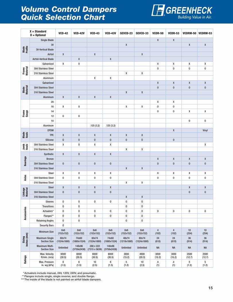
Volume Control Dampers Quick Selection Chart
X = StandardO = Optional VCD-42 VCD-42V VCD-43 VCD-43V SEVCD-23 SEVCD-33 VCDR-50 VCDR-53 VCDRM-50 VCDRM-53
Blad
e Pr
ofile
Single Blade X X
3V X X X
3V-Vertical Blade
Airfoil X X X
Airfoil-Vertical Blade X X
Fram
e M
ater
ial
Galvanized X X X X X X
304 Stainless Steel O O O O
316 Stainless Steel X X
Aluminum X X
Blad
eM
ater
ial
Galvanized X X X X
304 Stainless Steel O O O O
316 Stainless Steel X X
Aluminum X X X X
Fram
e Ga
uge
20 X X
16 X X X X O O
14 O O X X
12 O O
10 O O
Aluminum .125 (3.2) .125 (3.2)
Blad
eSe
als
EPDM X Vinyl
TPE X X X X X X
Silicone O O O O O O O
Jam
bSe
als 304 Stainless Steel X X X X X
316 Stainless Steel X X
Bear
ings
Synthetic X X X X
Bronze X X X X
304 Stainless Steel O O O O O O O O
316 Stainless Steel X X
Axle
s
Steel X X X X X X X X
304 Stainless Steel O O O O O O O O
316 Stainless Steel X X
Link
age
Mat
eria
l Steel X X X X X X
304 Stainless Steel O O O O O O
316 Stainless Steel X X
Acce
ssor
ies
Sleeves O O O O O O
Transitions O O O O
Actuators* O O O O O O O O O O
Flanges** O O O O O O
Retaining Angles O O O O
Security Bars O
Sizi
ng
inch
es (m
m) Minimum Size
6x6(152x152)
6x6(152x152)
6x6(152x152)
6x6(152x152)
6x6(152x152)
6x6(152x152)
4(102)
4(102)
10(254)
10 (254)
Maximum Single Section Size
60x74(1524x1880)
74x60(1880x1524)
60x74(1524x1880)
74x60(1880x1524)
48x74(1219x1880)
60x74(1524x1880)
24(610)
24(610)
36(914)
36(914)
Maximum Multi-Section Size
Unlimited148x96
(3759x2438)288 x 222
(7315 x 5639)148x96
(3759x2438)Unlimited Unlimited NA NA NA NA
Ratin
gs
Max. Velocityft/min. (m/s)
6000(30.5)
6000(30.5)
6000(30.5)
6000(30.5)
3000(15.2)
4000(20.3)
3000(15.2)
3000(15.2)
2500(12.7)
2500(12.7)
Max. Pressurein. wg (kPa)
6(1.5)
6(1.5)
10(2.5)
6(1.5)
5(1.2)
10(2.5)
4(1)
4(1)
5(1.2)
5(1.2)
* Actuators include manual, 24V, 120V, 240V, and pneumatic. ** Flanges include single, single reverse, and double flange. *** The inside of the blade is not painted on airfoil blade dampers.
®
16
Specialty Control Dampers ®
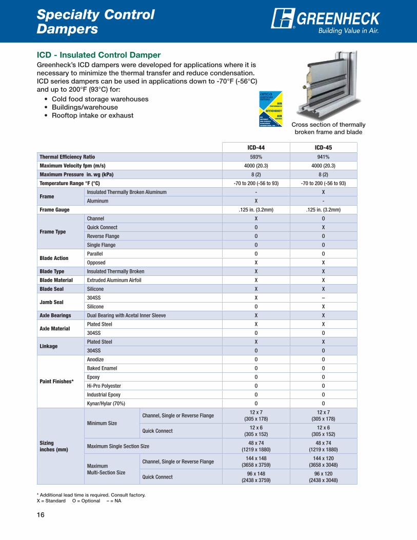
ICD - Insulated Control Damper
Greenheck’s ICD dampers were developed for applications where it is necessary to minimize the thermal transfer and reduce condensation. ICD series dampers can be used in applications down to -70°F (-56°C) and up to 200°F (93°C) for:
• Cold food storage warehouses • Buildings/warehouse • Rooftop intake or exhaust
Cross section of thermally broken frame and blade
ICD-44 ICD-45Thermal Efficiency Ratio 593% 941%
Maximum Velocity fpm (m/s) 4000 (20.3) 4000 (20.3)
Maximum Pressure in. wg (kPa) 8 (2) 8 (2)
Temperature Range °F (°C) -70 to 200 (-56 to 93) -70 to 200 (-56 to 93)
FrameInsulated Thermally Broken Aluminum - X
Aluminum X -
Frame Gauge .125 in. (3.2mm) .125 in. (3.2mm)
Frame Type
Channel X O
Quick Connect O X
Reverse Flange O O
Single Flange O O
Blade ActionParallel O O
Opposed X X
Blade Type Insulated Thermally Broken X X
Blade Material Extruded Aluminum Airfoil X X
Blade Seal Silicone X X
Jamb Seal304SS X –
Silicone O X
Axle Bearings Dual Bearing with Acetal Inner Sleeve X X
Axle MaterialPlated Steel X X
304SS O O
LinkagePlated Steel X X
304SS O O
Paint Finishes*
Anodize O O
Baked Enamel O O
Epoxy O O
Hi-Pro Polyester O O
Industrial Epoxy O O
Kynar/Hylar (70%) O O
Sizinginches (mm)
Minimum SizeChannel, Single or Reverse Flange
12 x 7 (305 x 178)
12 x 7 (305 x 178)
Quick Connect12 x 6
(305 x 152)12 x 6
(305 x 152)
Maximum Single Section Size48 x 74
(1219 x 1880)48 x 74
(1219 x 1880)
Maximum Multi-Section Size
Channel, Single or Reverse Flange144 x 148
(3658 x 3759)144 x 120
(3658 x 3048)
Quick Connect96 x 148
(2438 x 3759)96 x 120
(2438 x 3048)
* Additional lead time is required. Consult factory.X = Standard O = Optional – = NA

17
Specialty Control Dampers ®
AMCA Certified Energy Efficiency Performance
Greenheck Model ICD-44 has a Thermal Efficiency Ratio of 593%. Greenheck Model ICD-45 has a Thermal Efficiency Ratio of 941%.
A damper’s Thermal Efficiency Ratio (E) is a comparison of the thermal performance of the tested damper with that of a standard reference damper, which is a 3V blade damper with blade and jamb seals. A damper with the same thermal efficiency as the reference damper would have an E of 0%. A damper that is twice as efficient as the reference damper would have an E of 100%.
Test Information
Testing was conducted on a 36 in. x 36 in. (914mm x 914mm) sample in AMCA 500-D figure 5.10 per AMCA Standard 500-D’s Thermal Efficiency test.
Torque
Data are based on a torque of 9.0 in. lb./ft² (0.56 N·m) applied to close and seat the damper during the test.
Face & Bypass Dampers
The face and bypass dampers are used in applications where two dampers are connected together allowing one damper to open while the other damper closes.
X = StandardO = Optional FBH-23 FBH-33 FBH-43 FBV-23 FBV-33 FBV-43
F &
B
Styl
e Horizontal X X X
Vertical X X X
Blad
e Pr
ofile 3V X X
Airfoil X X X X
Mat
eria
l Galvanized X X X X
Aluminum X X
Blad
eSe
als TPE X X X X X X
Silicone O O O O O O
Bear
ings Synthetic X X X X X X
304 Stainless Steel O O O O O O
Axle
s Steel X X X X X X
304 Stainless Steel O O O O O O
Link
age
Mat
eria
l Steel X X X X X X
304 Stainless Steel O O O O O O
Sizi
ng
inch
es (m
m) Minimum Size
8x6(203x152)
8x6(203x152)
8x6(203x152)
8x6(203x152)
8x6(203x152)
8x6(203x152)
Maximum Single Section Size
48x74(1219x1880)
60x74(1524x1880)
60x74(1524x1880)
48x74(1219x1880)
60x74(1524x1880)
60x74(1524x1880)
Maximum Multi-Section Size (Face Only)
96 x 74(2438 x 1880)
96 x 74(2438 x 1880)
96 x 74(2438 x 1880)
96 x 74(2438 x 1880)
96 x 74(2438 x 1880)
96 x 74(2438 x 1880)
Ratin
gs
Max. Velocityft/min. (m/s)
3000(15.2)
4000(20.3)
6000(30.5)
3000(15.2)
4000(20.3)
6000(30.5)
Max. Pressurein. wg (kPa)
5(1.2)
10(2.5)
6(1.5)
5(1.2)
10(2.5)
6(1.5)
FBHFBH
FBVFBV
18
Balancing Dampers ®
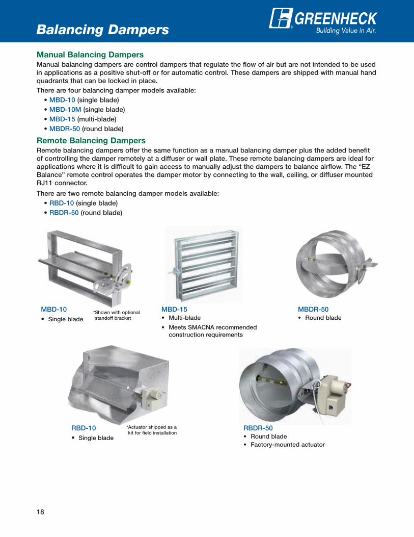
Manual Balancing Dampers
Manual balancing dampers are control dampers that regulate the flow of air but are not intended to be used in applications as a positive shut-off or for automatic control. These dampers are shipped with manual hand quadrants that can be locked in place.There are four balancing damper models available:
• MBD-10 (single blade)• MBD-10M (single blade)• MBD-15 (multi-blade)• MBDR-50 (round blade)
Remote Balancing Dampers
Remote balancing dampers offer the same function as a manual balancing damper plus the added benefit of controlling the damper remotely at a diffuser or wall plate. These remote balancing dampers are ideal for applications where it is difficult to gain access to manually adjust the dampers to balance airflow. The “EZ Balance” remote control operates the damper motor by connecting to the wall, ceiling, or diffuser mounted RJ11 connector.
There are two remote balancing damper models available:• RBD-10 (single blade)• RBDR-50 (round blade)
MBD-15• Multi-blade
• Meets SMACNA recommended construction requirements
MBDR-50• Round blade
* Shown with optional standoff bracket
MBD-10• Single blade
RBDR-50• Round blade • Factory-mounted actuator
* Actuator shipped as a kit for field installation
RBD-10• Single blade

19
Manual and Remote Balancing Dampers ®
Quick Selection ChartMBD-10 MBD-10M MBD-15 MBDR-50 RBD-10 RBDR-50
BladeProfile
Single Blade X X X
3V X
Round X X
Material Galvanized X X X X X X
FrameGauge
22 (0.8) X X X
20 (1) X X
16 (1.5) X
BearingsSynthetic X X X X
Bronze O
Axles Steel X X X
Linkage Material Steel X
Actuator
Manual Quadrant X X X X
1-1/2 in. Standoff Bracket O O X O
2 in. Standoff Bracket O O O O
Remote Powered 9 Volt Actuator
X X
SizingInches (mm)
Minimum6 x 4
(152 x 102)8 x 4
(203 x 102)6 x 6
(152 x 152)4
(102)6 x 4
(152 x 102)4
(102)
Maximum Single Section
36 x 12(914 x 305)
36 x 12(914 x 305)
48 x 60(1219 x 1524)
24(610)
36 x 12(914 x 305)
24(610)
Maximum Multi-Section
- -96 x 96
(2438 x 2438)- - -
X = Standard O = Optional
Velocity Pressure
0 1000 2000 3000 4000 5000 6000
MBD-10/10M
MBD-15
MBDR-50
RBD-10
RBDR-50
Feet per Minute (maximum)
0 1 2 3 4 5
MBD-10/10M
MBD-15
MBDR-50
RBD-10
RBDR-50
Inches wg (maximum)
A wide variety of accessories are available for the RBD and RBDR series. They include:• Diffuser connector• Wall plates with ports• Round wall/ceiling plate with single port• Single gang outlet box• EZ Balance handheld remote kit• Plenum and non-plenum rated cables• Cable connectors
EZ Balance handheld remote kit
clude:
00.DMP.1004 R9 1-2018 RGCopyright © 2018 Greenheck Fan Corp.P.O. Box 410 • Schofield, WI 54476-0410 • Phone (715) 359-6171 • greenheck.com
Prepared to Support
Green Building Efforts
As a result of our commitment to continuous improvement, Greenheck reserves the right to change
specifications without notice.
Specific Greenheck product warranties are located on greenheck.com within the product
area tabs and in the Library under Warranties.
Our Commitment
Drive Arrangement Definition
Damper Width
Dam
per H
eight
Actuator orManual Quadrant
Jackshaft
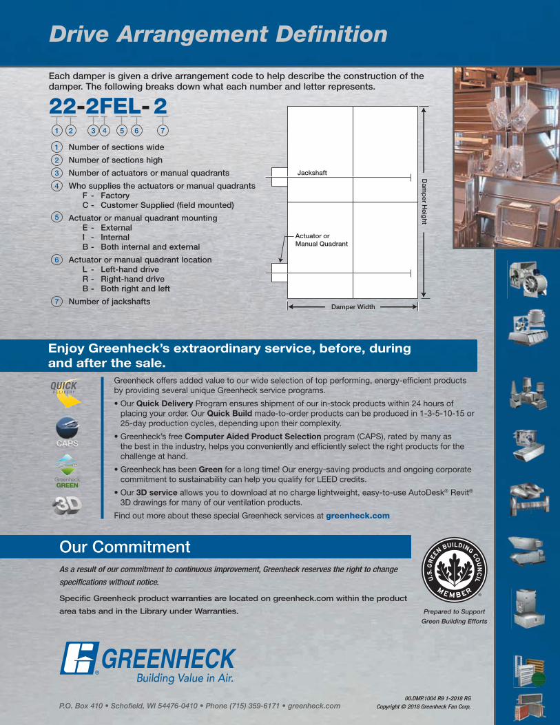
Each damper is given a drive arrangement code to help describe the construction of the damper. The following breaks down what each number and letter represents.
1 Number of sections wide
2 Number of sections high
3 Number of actuators or manual quadrants
4 Who supplies the actuators or manual quadrants F - Factory C - Customer Supplied (field mounted)5 Actuator or manual quadrant mounting
E - External I - Internal B - Both internal and external
6 Actuator or manual quadrant location L - Left-hand drive R - Right-hand drive B - Both right and left
7 Number of jackshafts
22-2FEL-21 2 3 4 5 6 7
Enjoy Greenheck’s extraordinary service, before, during
and after the sale.
Greenheck offers added value to our wide selection of top performing, energy-efficient products by providing several unique Greenheck service programs.
• Our Quick Delivery Program ensures shipment of our in-stock products within 24 hours of placing your order. Our Quick Build made-to-order products can be produced in 1-3-5-10-15 or 25-day production cycles, depending upon their complexity.
• Greenheck’s free Computer Aided Product Selection program (CAPS), rated by many as the best in the industry, helps you conveniently and efficiently select the right products for the challenge at hand.
• Greenheck has been Green for a long time! Our energy-saving products and ongoing corporate commitment to sustainability can help you qualify for LEED credits.
• Our 3D service allows you to download at no charge lightweight, easy-to-use AutoDesk® Revit® 3D drawings for many of our ventilation products.
Find out more about these special Greenheck services at greenheck.com