Huygens’ odd sympathy experiment revisited · Huygens’ odd sympathy experiment ... We repeat...
15
July 18, 2010 17:44 Nowy International Journal of Bifurcation and Chaos c World Scientific Publishing Company Huygens’ odd sympathy experiment revisited K. Czolczynski, P. Perlikowski, A. Stefanski, and T. Kapitaniak Division of Dynamics, Technical University of Lodz, Stefanowskiego 1/15, 90-924 Lodz, Poland [email protected] Abstract: We repeat Huygens’ experiment using real pendulum clocks in the same way as it was done originally, i.e., we hang two clocks on the same beam and observe the behavior of the pendulums. The clocks in the experiment have been selected in such a way to be as identical as possible. It has been observed that when the beam is allowed to move horizontally, the clocks can synchronize both in-phase and anti-phase. We perform computer simulations of the clocks’ behavior to answer the question how the nonidentity of the clocks influences the synchronization process. We show that even the clocks with significantly different periods of oscillations can synchronize, but their periods are modified by the beam motion so they are no more accurate. Keywords : Pendulum, clocks, synchronization, Huygens’ experiment 1. Introduction The phrase odd sympathy (or exactly the odd kind of sympathy) was used by Dutch physicist Christiaan Huygens (1629-95) in a letter to the Royal Society of London pertaining to the tendency of two pendulums to synchronize, or anti-synchronize, when mounted together on the same beam [Huygens, 1665]. The original drawing showing this experiment is shown in Fig. 1. Huygens, the inventor of the pendulum clock [Huygens, 1673], noticed the effect while lying in bed. Two pendulum clocks, mounted together, will always end up swinging in exactly opposite directions, regardless of their respective individual motion. This was one of the first observations of the phenomenon of coupled harmonic oscillators, which have many applications in physics [Pikovsky et al., 2001; Blekham, 1988]. Huygens originally believed the synchronization occurs due to air currents shared between the two pendulums, but later after performing several simple tests he dismissed this idea and attributed sympathetic motion of pendulums to imperceptible movement in the beam from which both pendulums are suspended. Recently, this idea has been rediscussed by a few groups of researchers which tested Huygens’ idea 1
Transcript of Huygens’ odd sympathy experiment revisited · Huygens’ odd sympathy experiment ... We repeat...
July 18, 2010 17:44 Nowy
International Journal of Bifurcation and Chaosc© World Scientific Publishing Company
Huygens’ odd sympathy experiment revisited
K. Czolczynski, P. Perlikowski, A. Stefanski, and T. KapitaniakDivision of Dynamics, Technical University of Lodz, Stefanowskiego 1/15, 90-924 Lodz, Poland
Abstract: We repeat Huygens’ experiment using real pendulum clocks in the same way as itwas done originally, i.e., we hang two clocks on the same beam and observe the behavior of thependulums. The clocks in the experiment have been selected in such a way to be as identical aspossible. It has been observed that when the beam is allowed to move horizontally, the clockscan synchronize both in-phase and anti-phase. We perform computer simulations of the clocks’behavior to answer the question how the nonidentity of the clocks influences the synchronizationprocess. We show that even the clocks with significantly different periods of oscillations cansynchronize, but their periods are modified by the beam motion so they are no more accurate.
Keywords: Pendulum, clocks, synchronization, Huygens’ experiment
1. Introduction
The phrase odd sympathy (or exactly the odd kind of sympathy) was used by Dutch physicist
Christiaan Huygens (1629-95) in a letter to the Royal Society of London pertaining to the tendency of
two pendulums to synchronize, or anti-synchronize, when mounted together on the same beam [Huygens,
1665]. The original drawing showing this experiment is shown in Fig. 1. Huygens, the inventor of the
pendulum clock [Huygens, 1673], noticed the effect while lying in bed. Two pendulum clocks, mounted
together, will always end up swinging in exactly opposite directions, regardless of their respective individual
motion. This was one of the first observations of the phenomenon of coupled harmonic oscillators, which
have many applications in physics [Pikovsky et al., 2001; Blekham, 1988]. Huygens originally believed the
synchronization occurs due to air currents shared between the two pendulums, but later after performing
several simple tests he dismissed this idea and attributed sympathetic motion of pendulums to imperceptible
movement in the beam from which both pendulums are suspended.
Recently, this idea has been rediscussed by a few groups of researchers which tested Huygens’ idea
1

July 18, 2010 17:44 Nowy
2 Czolczynski et. al.
Fig. 1: An original drawing describing the Huygens’ experiment [Pikovsky et al., 2001; Huygens, 1665].
[Pogromsky et al., 2001; Bennet et al., 2002; Senator, 2006; Dilao, 2009; Kumon et al., 2002; Fradkov, &
Andrievsky, 2007; Pantaleone, 2002; Ulrichs et al., 2009; Czolczynski et al., 2009b]. To explain Huygens’
observations Bennett et al. [2002] built an experimental device consisting of two interacting pendulum
clocks hanged on a heavy support which was mounted on a low-friction wheeled cart. The device moves
by the action of the reaction forces generated by the swing of two pendulums and the interaction of the
clocks occurs due to the motion of the clocks’ base. It has been shown that to repeat Huygens’ results, the
high precision (the precision that Huygens certainly could not achieve) is necessary.
The system very close to one considered by Huygens (i.e., two pendulum clocks with cases hanging from
the same beam) has been investigated by Senator [2006] who developed a qualitative approximate theory
of clocks’ synchronization. This theory explicitly includes the essential nonlinear elements of Huygens’
system, i.e., escapement mechanisms but also includes many simplifications.
A device mimicking Huygens’ clock experiment, the so-called ”coupled pendulums of the Kumamoto
University” [Kumon et al., 2002], consists of two pendula which suspension rods are connected by a weak
spring, and one of the pendulums is excited by an external rotor. The numerical results of Fradkov and

July 18, 2010 17:44 Nowy
Huygens’ odd sympathy 3
Andrievsky [2007] show simultaneous approximate in-phase and anti-phase synchronization. Both types of
synchronization can be obtained for different initial conditions. Additionally, it has been shown that for
small difference in the pendulums frequencies they may not synchronize.
The problems of clocks synchronization is also Blekhman [1988] where the clocks have been modeled
as van-der Pol’s type self-excited oscillators.
In this paper we repeat the Huygens’ experiment using real pendulum clocks. We have been trying to
perform the experiment in the same way as Huygens did it. We hang two clock on the same beam and
observe the behavior of the pendulums. The clocks in experiment have been selected in such a way to
be as identical as possible. It has been observed that when the beam is allowed to move horizontally the
clocks can synchronize both in-phase and anti-phase. As we notice some small differences in the pendulum
lengths and periods (so small to be identified in the Huygens’ time) we perform computer simulations to
answer the question: how the nonidentity of the clocks influences the synchronization process. We show
that even the clocks with significantly different periods of oscillations can synchronize, but their periods
are modified by the beam motion so they are obviously no more accurate.
This paper is organized as follows. In Sec. 2 we have described the results of our experiments in which
we used contemporary mechanical pendulum clocks. Sec. 3 presents the results of our numerical simulations.
It describes the model of the clocks which has been used and answer the question how the non-identity of
the clocks influences the synchronization process. Finally, we summarize our results in Sec.4.
2. Experimental observations
For our experiments we take two contemporary pendulum clocks (type: SN–13, produced in 2003 in Fac-
tory of Clocks in Torun, Poland) which are shown in Fig. 2(a-c). These clocks have typical escapement
mechanisms described in [Rowlings, 1944; Czolczynski et al., 2009a] and pendulums of the length 0.269
[m] and mass 0.158 [kg]. The total mass of the clock is equal to 5.361 [kg]. The clocks are placed in the
wooden cases. The clocks in experiment have been selected in such a way to be as identical as possible but
we noticed a small time difference of 1 [s] after 24 hours. When the clocks are hanging on the wall as in
Fig. 2(a) no synchronization has been observed.
Next the clock has been hanged on the wooden beam (length - 1.13 [m], mass - 1.45 [kg]) and located
on two chairs as in the original Huygens experiment of Fig. 1. Our setup is shown in Fig. 2(b). In this case

July 18, 2010 17:44 Nowy
4 Czolczynski et. al.
(b)(a)
(c)
Fig. 2: Experiments with two pendulum clocks: (a) clocks hang on the wall, (b) clocks hang from the beamlocated on the chairs’ backs, (c) clocks hang from the beam which can roll horizontally on the tables’ desks.
we have not observed the clocks’ synchronizations but we noticed the frequent switches off of one of the
clocks (amplitude death of its pendulum). This effect occurs due to the spherical motion of the clocks’ cases
and subsequently their pendulums. The spherical motion of the pendulums (with the too large amplitudes)
switches off the escapement mechanism which is designed for the planar motion of the pendulum. To reduce
the amplitudes of the spherical oscillations we have balanced the clocks by adding additional masses into
their cases but we have not observed the synchronization.
The synchronization has been observed in the setup shown in Fig. 2(c). Two chairs have been replaced
by the tables with a flat horizontal desks. The beam with hanging clocks has been located on the rolls
which can roll on the table desks. We have been trying to reduce friction by polishing the surfaces of the
beam, table desks and rolls. Depending on initial conditions it has been possible to observe both in-phase

July 18, 2010 17:44 Nowy
Huygens’ odd sympathy 5
kx
cx
j2j
1 m
m
x
l1
l2
M
Fig. 3: The model of the system.
and anti-phase synchronization of clocks’ pendulums.
In -phase and anti-phase synchronization can be also observed in the case when the clocks’ cases are
mounted to the beam (the relative case-beam motion is suppressed). However, this case is closer to Bennet
et al. [2002] experiment than to original Huygens one.
3. Numerical simulations
3.1. Model
The analyzed system is shown in Fig. 3, it consists of the rigid beam and two clocks suspended on it. The
beam can move in a horizontal direction, its movement is described by coordinate x. The mass of the beam
is connected to the refuge of a linear spring and linear damper kx and cx. Clocks’ pendulums have the same
mass m but different lengths l1 and l2. The motion of the pendulums is described by angles ϕ1 and ϕ2 and
is damped by dampers (not shown in Fig. 1) with damping coefficients cϕ1 and cϕ2. The pendulums are
driven by the escapement mechanism described in details in [Rowlings, 1944; Czolczynski et al., 2009a].
Notice that when the swinging pendulums do not exceed a certain angle γN the escapement mechanisms
generate the constant moments MN1 and MN2. This mechanism acts in two successive steps (the first
step is followed by the second one and the second one by the first one). In the first step if 0 < ϕi < γN
(i = 1, 2) then Mi = MNi and when ϕi < 0 then MNi = 0. For the second stage one has for −γN < ϕi < 0
Mi = −MNi and for ϕi > 0 MNi = 0.
The equations of motion are as follows:
ml2i ϕi + mlix cosϕi + cϕiϕi + mgli sinϕi = Mi i = 1, 2,
(M + 2m) x + cxx + kxx +∑2
i=1
(mliϕi cosϕi −mliϕ
2i sinϕi
)= 0.
(1)
All the parameters of Eq. (1) are dimensionless. One should distinguish between three periods of
pendulums’ oscillations; (i) the period of the pendulums’ oscillations in the case when the beam is at rest

July 18, 2010 17:44 Nowy
6 Czolczynski et. al.
0.25
-0.25
0.0
-0.5
0.5
j1 j
2
N0 1 2 3 4 5 6
j1 j
2
Fig. 4: Oscillations of two pendulum; scale of pendulum 2: ξ = 0.5.
denoted by Ti0, (i = 1, 2), (ii) the periods of the pendulums oscillating on the moving beam (i.e., the time in
which the pendulum reaches the maximum deflection and is moving in the same direction) denoted by Ti,
(iii) the period of the oscillations of the beam-pendulums system denoted by T . Under these assumptions
the dynamics of the pendulum clock is described by a self-excited oscillator with a limit cycle [Andronov,
1966] (see also [Moon & Stiefel, 2006]). The dynamics of the other type of the clock escapement mechanism,
i.e., verge and foliot mechanism is described in [Rowlings, 1944; Roup et al., 2003; Lepschy et al., 1993].
In our numerical calculations we consider the following parameter values. The first pendulum is char-
acterized by: m = 1.0, l1 = g/4π2 = 0.2485 (i.e., in the case when the beam is at rest its period of
limit cycle oscillations is equal to T0 = 1 and its frequency is equal to α10 = 2π; g = 9.81), cϕ1 = 0.01,
MN1 = 0.075, γN = 5◦ (i.e., when the beam is at rest the pendulum performs the oscillations with ampli-
tude Φ10 = 15◦). The second pendulum has the same mass m and γN Its length is equal to l2 = ξ2l1 (i.e.,
α2 = α1/ξ and T20 = ξT10) and cϕ2 = ξcϕ1, MN2 = ξMN1. The coefficient ξ is called the scale factor of
the second pendulum. Proportionality of the damping coefficients and escapement mechanisms moments
of both pendulums results in the equality of the amplitudes Φ20 = Φ10. In Fig. 4 we show the oscillations of
pendulums 1 (thick line) and 2 (thin line) suspended on the nonmoving beam. The displacements of both
pendulums ϕ1 and ϕ2 versus time represented by the number of oscillation periods of the first pendulum
N are presented. As ξ = 0.5 one can observe that T20 = 0.5T10 and that the amplitudes of both pendulums
are the same. Beam’s parameters are as follows. Its mass is assumed to be M = 5.0, the stiffness kx and
July 18, 2010 17:44 Nowy
Huygens’ odd sympathy 7
damping coefficients cx are related to the beam mass, i.e., kx = 0.1M , cx = M .
3.2. Different types of synchronization
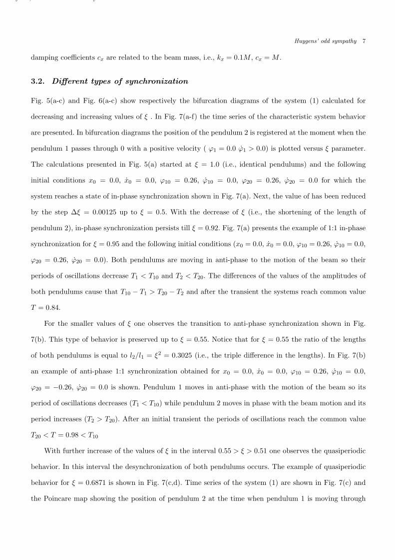
Fig. 5(a-c) and Fig. 6(a-c) show respectively the bifurcation diagrams of the system (1) calculated for
decreasing and increasing values of ξ . In Fig. 7(a-f) the time series of the characteristic system behavior
are presented. In bifurcation diagrams the position of the pendulum 2 is registered at the moment when the
pendulum 1 passes through 0 with a positive velocity ( ϕ1 = 0.0 ϕ1 > 0.0) is plotted versus ξ parameter.
The calculations presented in Fig. 5(a) started at ξ = 1.0 (i.e., identical pendulums) and the following
initial conditions x0 = 0.0, x0 = 0.0, ϕ10 = 0.26, ϕ10 = 0.0, ϕ20 = 0.26, ϕ20 = 0.0 for which the
system reaches a state of in-phase synchronization shown in Fig. 7(a). Next, the value of has been reduced
by the step ∆ξ = 0.00125 up to ξ = 0.5. With the decrease of ξ (i.e., the shortening of the length of
pendulum 2), in-phase synchronization persists till ξ = 0.92. Fig. 7(a) presents the example of 1:1 in-phase
synchronization for ξ = 0.95 and the following initial conditions (x0 = 0.0, x0 = 0.0, ϕ10 = 0.26, ϕ10 = 0.0,
ϕ20 = 0.26, ϕ20 = 0.0). Both pendulums are moving in anti-phase to the motion of the beam so their
periods of oscillations decrease T1 < T10 and T2 < T20. The differences of the values of the amplitudes of
both pendulums cause that T10 − T1 > T20 − T2 and after the transient the systems reach common value
T = 0.84.
For the smaller values of ξ one observes the transition to anti-phase synchronization shown in Fig.
7(b). This type of behavior is preserved up to ξ = 0.55. Notice that for ξ = 0.55 the ratio of the lengths
of both pendulums is equal to l2/l1 = ξ2 = 0.3025 (i.e., the triple difference in the lengths). In Fig. 7(b)
an example of anti-phase 1:1 synchronization obtained for x0 = 0.0, x0 = 0.0, ϕ10 = 0.26, ϕ10 = 0.0,
ϕ20 = −0.26, ϕ20 = 0.0 is shown. Pendulum 1 moves in anti-phase with the motion of the beam so its
period of oscillations decreases (T1 < T10) while pendulum 2 moves in phase with the beam motion and its
period increases (T2 > T20). After an initial transient the periods of oscillations reach the common value
T20 < T = 0.98 < T10
With further increase of the values of ξ in the interval 0.55 > ξ > 0.51 one observes the quasiperiodic
behavior. In this interval the desynchronization of both pendulums occurs. The example of quasiperiodic
behavior for ξ = 0.6871 is shown in Fig. 7(c,d). Time series of the system (1) are shown in Fig. 7(c) and
the Poincare map showing the position of pendulum 2 at the time when pendulum 1 is moving through
July 18, 2010 17:44 Nowy
8 Czolczynski et. al.
0.0
-0.5
0.5
j2
0.0
-0.5
0.5
f2
gN
f2f1f1
0.0
-0.5
0.5
j2
0.51.0 0.8 0.60.70.9x
0.51.0 0.8 0.60.70.9 x
0.50.52 0.512 0.5040.5080.516x
(a)
(b)
(c)
1:2
Fig. 5: (a) bifurcation diagram of the system (1) for decreasing ξ; ϕ10 = ϕ20 = 0.26, end with ξ = 0.5;(b) minima of amplitudes of pendulums oscillations; (c) enlargement of (a) in the neighborhood of 1:2synchronization.
zero with the positive velocity is presented in Fig. 7(d). The closed curve at the Poincare map confirms
that the behavior is quasiperiodic.
The subsequent change in the pendulums’ configuration leads to 1:2 synchronization explained in Fig.
7(e) (the synchronization obtained by doubling the period of the pendulum 2 ( ξ = 0.51)). Common period
of pendulums oscillations is equal to the period of pendulum 1 T1 and two periods of pendulum 2, i.e.,
T = T1 = 2T2 = 0.94. Noteworthy is the fact that in the case of nonmoving beam this synchronization
would occur for ξ = 0.5 = 1/2 and T1 = 2T2. In the case of the oscillating beam this transition is shifted
as due to the different pendulums’ locations ϕ1 6= ϕ2 and their different lengths l1 6= l2 the resultant of the
forces with which pendulums act on the beam is not always equal to zero.
July 18, 2010 17:44 Nowy
Huygens’ odd sympathy 9
0.0
-0.5
0.5
j2
0.0
-0.5
0.5
f2
gN
f2f1f1
0.0
-0.5
0.5
j2
0.51.0 0.8 0.60.70.9x
3:4 2:3 3:5 1:2
0.51.0 0.8 0.60.70.9 x
0.6860.691 0.689 0.6870.6880.690x
(a)
(b)
(c)
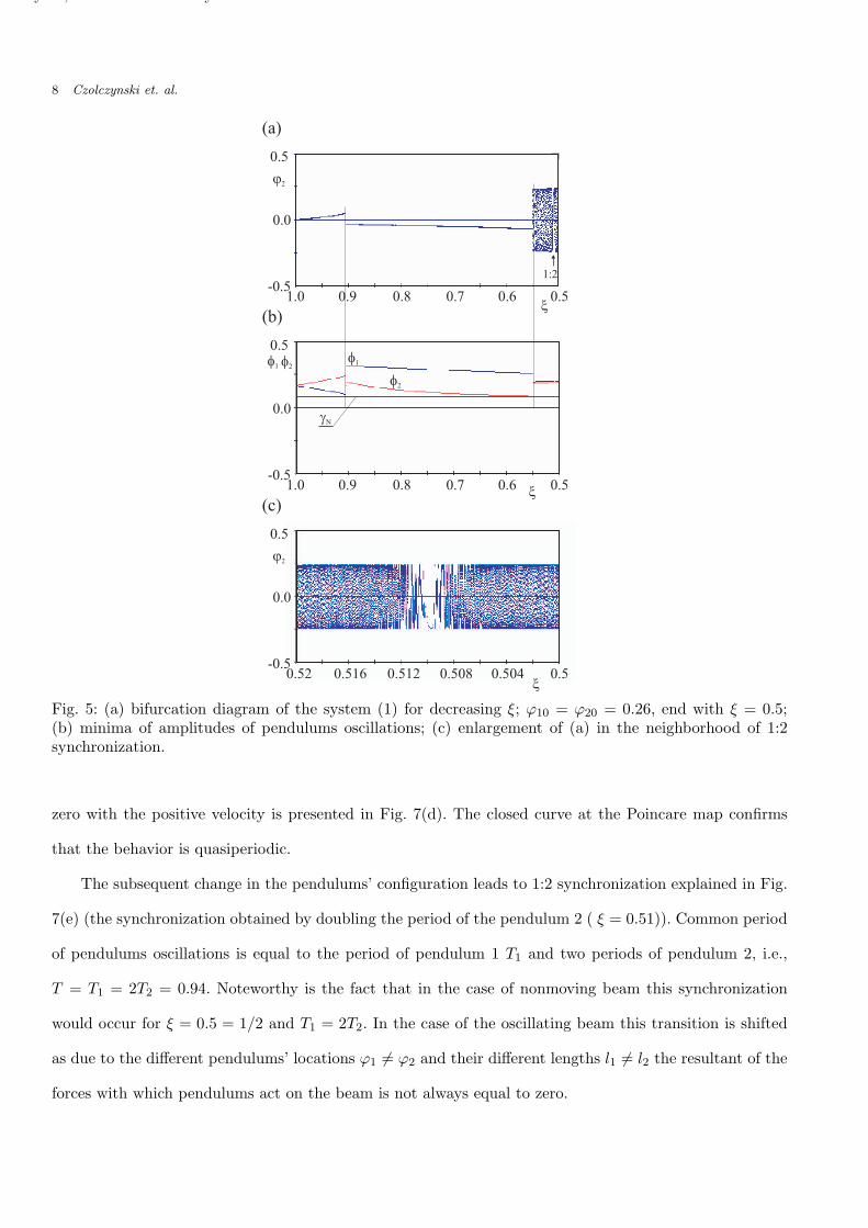
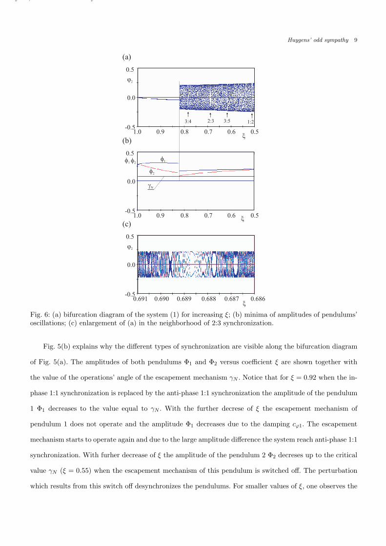
Fig. 6: (a) bifurcation diagram of the system (1) for increasing ξ; (b) minima of amplitudes of pendulums’oscillations; (c) enlargement of (a) in the neighborhood of 2:3 synchronization.
Fig. 5(b) explains why the different types of synchronization are visible along the bifurcation diagram
of Fig. 5(a). The amplitudes of both pendulums Φ1 and Φ2 versus coefficient ξ are shown together with
the value of the operations’ angle of the escapement mechanism γN . Notice that for ξ = 0.92 when the in-
phase 1:1 synchronization is replaced by the anti-phase 1:1 synchronization the amplitude of the pendulum
1 Φ1 decreases to the value equal to γN . With the further decrese of ξ the escapement mechanism of
pendulum 1 does not operate and the amplitude Φ1 decreases due to the damping cϕ1. The escapement
mechanism starts to operate again and due to the large amplitude difference the system reach anti-phase 1:1
synchronization. With furher decrease of ξ the amplitude of the pendulum 2 Φ2 decreses up to the critical
value γN (ξ = 0.55) when the escapement mechanism of this pendulum is switched off. The perturbation
which results from this switch off desynchronizes the pendulums. For smaller values of ξ, one observes the
July 18, 2010 17:44 Nowy
10 Czolczynski et. al.
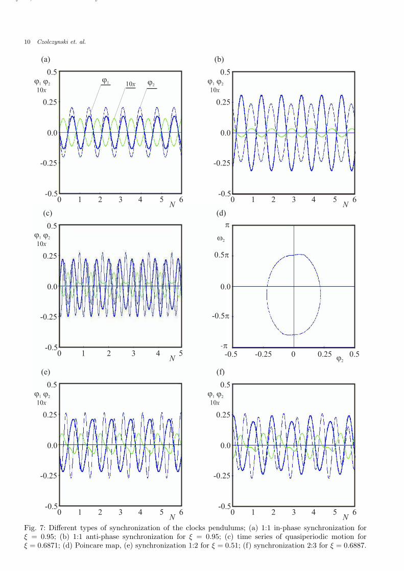
Fig. 7: Different types of synchronization of the clocks pendulums; (a) 1:1 in-phase synchronization forξ = 0.95; (b) 1:1 anti-phase synchronization for ξ = 0.95; (c) time series of quasiperiodic motion forξ = 0.6871; (d) Poincare map, (e) synchronization 1:2 for ξ = 0.51; (f) synchronization 2:3 for ξ = 0.6887.
July 18, 2010 17:44 Nowy
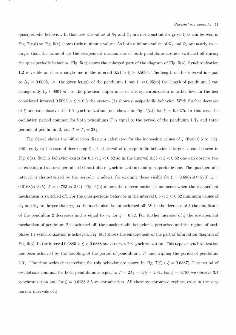
Huygens’ odd sympathy 11
quasiperiodic behavior. In this case the values of Φ1 and Φ2 are not constant for given ξ as can be seen in
Fig. 7(c,d) so Fig. 5(c) shows their minimum values. As both minimun values of Φ1 and Φ2 are nearly twice
larger than the value of γN the escapement mechanisms of both pendulums are not switched off during
the quasiperiodic behavior. Fig. 5(c) shows the enlarged part of the diagram of Fig. 5(a). Synchronization
1:2 is visible on it as a single line in the interval 0.51 > ξ > 0.5095. The length of this interval is equal
to ∆ξ = 0.0005, i.e., the given length of the pendulum 1, say l1 ≈ 0.25[m] the length of pendulum 2 can
change only by 0.0001[m], so the practical importance of this synchronization is rather low. In the last
considered interval 0.5095 > ξ > 0.5 the system (1) shows quasiperiodic behavior. With further decrease
of ξ one can observe the 1:3 synchronization (not shown in Fig. 5(a)) for ξ = 0.3375. In this case the
oscillation period common for both pendulums T is equal to the period of the pendulum 1 T1 and three
periods of pendulum 2, i.e., T = T1 = 3T2.
Fig. 6(a-c) shows the bifurcation diagram calculated for the increasing values of ξ (from 0.5 to 1.0).
Differently to the case of decreasing ξ , the interval of quasiperiodic behavior is larger as can be seen in
Fig. 6(a). Such a behavior exists for 0.5 < ξ < 0.82 so in the interval 0.55 < ξ < 0.82 one can observe two
co-existing attractors; periodic (1:1 anti-phase synchronization) and quasiperiodic one. The quasiperiodic
interval is characterized by the periodic windows, for example these visible for ξ = 0.68875(≈ 2/3), ξ =
0.6168(≈ 3/5), ξ = 0.783(≈ 3/4). Fig. 6(b) allows the determination of moments when the escapement
mechanism is switched off. For the quasiperiodic behavior in the interval 0.5 < ξ < 0.82 minimum values of
Φ1 and Φ2 are larger than γN so the mechanism is not switched off. With the decrease of ξ the amplitude
of the pendulum 2 decreases and is equal to γN for ξ = 0.82. For further increase of ξ the ecscapement
mechanism of pendulum 2 is switched off, the quasiperiodic behavior is perturbed and the regime of anti-
phase 1:1 synchronization is achieved. Fig. 6(c) shows the enlargement of the part of bifurcation diagram of
Fig. 6(a). In the interval 0.6885 < ξ < 0.6888 one observes 2:3 synchronization. This type of synchronization
has been achieved by the doubling of the period of pendulum 1 T1 and tripling the period of pendulum
2 T2. The time series characteristic for this behavior are shown in Fig. 7(f) ( ξ = 0.6887). The period of
oscillations common for both pendulums is equal to T = 2T1 = 3T2 = 1.91. For ξ = 0.783 we observe 3:4
synchronization and for ξ = 0.6158 3:5 synchronization. All these synchronized regimes exist in the very
narrow intervals of ξ.

July 18, 2010 17:44 Nowy
12 Czolczynski et. al.
The bifurcation diagrams of Figs 5(a-c) and 6(a-c) show the existence of two different attractors for
some ξ-intervals. For 1.0 > ξ > 0.92 one can observe 1:1 in-phase and 1:1 anti-phase synchronization,
and for 0.82 > ξ > 0.55 1:1 anti-phase synchronization and quasiperiodic behavior (or 1:2, 2:3, 3:4,
. . . synchronization in the narrow windows).
The question how the co-existing attractors are sensitive to the external perturbations cannot be
generally answered as both phase and parameter spaces of the system are high-dimensional. We partially
address this problem by performing the following experiment. Having assumed that the system is operating
on one of the coexisting attractor we perturb the state of pendulum 2 and observe to which attractor the
system will approach. Such a procedure allows the estimation of the basins of attraction of the coexisting
attractors shown in Fig. 8(a-c).
Perturbation of the state of pendulum 2 means the change of its position to the new state given by ϕ20
and ϕ20. Other system parameters, i.e., ϕ1, ϕ2, x and x are not changed at the moment of perturbation.
Then the system (1) performs the transient evolution which leads to one of the coexisting attractors.
Notice that such perturbation can influence the acting of the escapement mechanism. If in the moment of
perturbation the mechanism is in the first stage (see Eqs. in Sec. 3.1) and new value of ϕ20 is larger than
γN , the mechanism moves to step 2. When in the unperturbed state the mechanism is in step 2 and new
value of ϕ20 is smaller than −γN , the mechanism goes to step 1. For other cases the perturbation has no
influence on the acting of the escapement mechanism.
In the example presented in Fig. 8(a) we assume that the system (1) performs 1:1 in-phase synchroniza-
tion for ξ = 0.95 (the coexisting attractor is anti-phase 1:1 synchronization). When the system has been
in the state given by: ϕ1 = 0.0, ϕ1 = 0.9616, ϕ2 = 0.01808, ϕ2 = 1.4945, x = −0.001635, x = −0.080947
pendulum 2 has been perturbed to the state given by (ϕ20, ϕ20). The initial perturbations ( ϕ20, ϕ20) after
which system (1) returns to the 1:1 in-phase synchronization are shown in black and these after the system
goes to anti-phase 1:1 synchronization are shown in black.
Fig. 8(b) presents the results obtained for ξ = 0.95 and the initial state given by ϕ1 = 0.0, ϕ1 = 1.9525,
ϕ2 = −0.0207, ϕ20 = −1.48, x = −0.000267, x0 = −0.0221, i.e., the system has been on the 1:1 anti-
phase synchronization attractor at the moment of perturbation. The basins of in-phase and anti-phase
synchronization are shown respectively in white and black.

July 18, 2010 17:44 Nowy
Huygens’ odd sympathy 13
0.01.5
antiphase
antiphase
antiphase
in phase
synchr. 2:3
in phase
0.0
4.03.0
2.0
-4.00.0
-2.0
j20j20
j20
00
0
-0.2-0.2
-0.2
0.20.2
0.2
(b)(a)
(c)
j20
.
j20
.j20.
Fig. 8: Basins of attraction of the co-existing attractors; (a) ξ = 0.95; (b) ξ = 0.95; (c) ξ = 0.6887.
For ξ = 0.6887 system (1) has two attractors; 1:1 anti-phase and 2:3 synchronization (see Fig. 8(c).
In the time of perturbation the system has been in the state: ϕ1 = 0.0, ϕ1 = 1.8385, ϕ2 = −0.05257,
ϕ2 = −0.558, x = 0.00004, x0 = −0.0559 exhibiting 1:1 anti-phase synchronization. The basins of 1:1
anti-phase and 2:3 synchronization are shown respectively in white and black in Fig. 8(c).
4. Conclusions
We show that two clocks hanging on the same beam can synchronize both in-phase and anti-phase. The
synchronization has been observed when the beam has been located on the rolls which allowed its horizontal

July 18, 2010 17:44 Nowy
14 Czolczynski et. al.
movement. Additionally, the clocks have to be hanged in such a way to avoid (reduce) the spherical motion
of their cases.
Although the clocks in experiment have been selected in such a way to be as identical as possible,
they have some small differences in the pendulum lengths and periods (too small to be identified in the
Huygens’ times). We perform computer simulations to answer the question: how the nonidentity of the
clocks influences the synchronization process. It has been shown that even the clocks with significantly
different periods of oscillations can synchronize, but their periods are modified by the beam motion so
they are obviously no more accurate. Our numerical studies show that the anti-phase synchronization is
dominant in the parameters space.
Additionally, to in-phase and anti-phase synchronization we identify the regions of quasiperiodic oscil-
lations of pendulums and phase locking regions of 1:2, 2:3, 3:4, . . . synchronization. It has been shown that
when the amplitude of oscillations of one of the pendulums decreases (as the result of the beam motion)
to the value smaller than N the escapement mechanism is temporarily switched off and the systems move
to the coexisting attractor after this mechanism is switched on again.
Acknowledgment
PP. acknowledges the support from Foundation for Polish Science (the START fellowship). K.C, A.S. and
T.K. acknowledge the support of Polish Department for Scientific Research (DBN) under project No. N N
501 0710 33.
References
Andronov, A., Witt, A. & Khaikin, S. [1966] Theory of Oscillations, (Pergamon, Oxford, UK).
Bennet, M., Schatz, M. F., Rockwood, H. & Wiesenfeld K. [2002] ”Huygens’ Clocks,” Proc. Roy. Soc.
London A 458 563-579.
Blekham, I.I. [1988] Synchronization in Science and Technology, (ASME, New York, USA).
Czolczynski, K., Perlikowski, P., Stefanski, A. & Kapitaniak, T. [2009a] ”Clustering and synchroniza-
tion of n Huygens’ clocks,” Physica A 388, 5013–5023.
Czolczynski, K., Perlikowski, P., Stefanski, A. & Kapitaniak, T. [2009b] ”Clustering of Huygens’
clocks,” Prog. Theor. Phys. 122, 1027–1033.

July 18, 2010 17:44 Nowy
Huygens’ odd sympathy 15
Dilao, R. [2009] ”Antiphase and in-phase synchronization of nonlinear oscillators: The Huygens’s clocks
system,” Chaos 19, 023118.
Fradkov, A.L. & Andrievsky, B. [2007] ”Synchronization and phase relations in the motion of two-
pendulum system,” Int. J. Non-linear Mech. 42, 895–901.
Huygens, C. [1665] Letter to de Sluse, In: Oeuveres Completes de Christian Huygens (letters; no. 1333
of 24 February 1665, no. 1335 of 26 February 1665, no. 1345 of 6 March 1665), (Societe Hollandaise Des
Sciences, Martinus Nijhoff, La Haye).
Huygens, C. [1673] C. Horoloqium Oscilatorium, (Apud F. Muquet, Parisiis, 1673); English translation:
The pendulum clock , (Iowa State University Press, Ames).
Kumon, M., Washizaki, R., Sato, J., Mizumoto, R.K.I. & Iwai, Z. [2002] ”Controlled synchronization
of two 1-DOF coupled oscillators,” Proceedings of the 15th IFAC World Congress, Barcelona.
Lepschy, A. M., Mian, G.A. & Viaro, U. [1992] ”Feedback control in ancient water and mechanical
clocks,” IEEE Trans. Education 35, 3–10.
Moon, F.C. & Stiefel, P.D. [2006] ”Coexisting chaotic and periodic dynamics in clock escapements,”
Phil. Trans. R. Soc. A 364, 2539–2564.
Pantaleone, J. [2002] ”Synchronization of metronomes,” Am. J. Phys. 70, 992–1000.
Pikovsky, A., Rosenblum, M. & Kurths, J. [2001] Synchronization: An Universal Concept in Nonlinear
Sciences, (Cambridge University Press, Cambridge, UK).
Pogromsky, A. Yu., Belykh, V.N. & Nijmeijer, H. [2003] ”Controlled synchronization of pendula,”
Proceedings of the 42nd IEEE Conference on Design and Control, 4381–4385.
Roup, A.V., Bernstein, D.S., Nersesov, S.G., Haddad, W.S. & Chellaboina, V. [2003] ”Limit cycle
analysis of the verge and foliot clock escapement using impulsive differential equations and Poincare
maps,” Int. J. Control 76, 1685–1698.
Rowlings, A.L. [1944] The science of clocks and watches, (Pitman, New York, USA).
Senator, M. [2006] ”Synchronization of two coupled escapement-driven pendulum clocks,” Journal
Sound and Vibration 291, 566–603.
Ulrichs, H., Mann, A. & Parlitz, U. [2009] ”Synchronization and chaotic dynamics of coupled mechan-
ical metronomes,” Chaos 19 043120.