HUMMBUG™ - wombatcar.com · A. Remove the battery hold down hardware, rear floor heater lever,...
62
HUMMBUG™ Assembly Manual May 1999 The Hummbug™ is an original design, with all rights reserved. Appropriate trademarks, copyrights, and design patents have been granted or are pending. Unauthorized use is strictly prohibited and will be prosecuted. Hummbug Fiberglass Kit Cars PMB #234 7904 NE 6 th Avenue, Suite B Vancouver, WA 98665-8107 Phone: (360) 335-8215 Fax: (360) 335-8425 Email: [email protected] Website: http://www.hummbug.com
Transcript of HUMMBUG™ - wombatcar.com · A. Remove the battery hold down hardware, rear floor heater lever,...

HUMMBUG™ Assembly Manual
May 1999
The Hummbug™ is an original design, with all rights reserved. Appropriate trademarks, copyrights, and design patents have been granted or are pending.
Unauthorized use is strictly prohibited and will be prosecuted.
Hummbug Fiberglass Kit Cars PMB #234
7904 NE 6th Avenue, Suite B Vancouver, WA 98665-8107
Phone: (360) 335-8215 Fax: (360) 335-8425 Email: [email protected]
Website: http://www.hummbug.com

Hummbug Assembly Manual
May 1999
Foreword The Hummbug is a relatively new kit and we are still
working on the assembly manual to make it as comprehensive as possible We welcome any corrections, comments, and suggestions you may have to improve this manual. Please mention which version you have when you refer to the manual.
It is important to us that you complete your kit. Call us with any questions. We do not have full-time staff in the Hummbug office so our hours are unpredictable. Phone us between 8:00 am and 10:00 pm Pacific Time. (Between 9:00 am and 10:00 am is your best chance to catch Karl in.)
If you leave a phone message, fax, or email please detail your question so we can be prepared when we get back to you. Also, leave the best times and numbers for us to contact you. We will respond as quickly as we can.
You can contact us via
• Phone: (360) 335-8215
• Fax: (360) 335-8425
• E-Mail: [email protected]

Hummbug™ Assembly Manual
Table of Contents
Section Number of Pages in Section Assembly Outline ..........................................................................4
A Brief over view of the steps to complete your Hummbug.
Donors & Parts..............................................................................4 Notes about choosing a donor vehicle and parts for your Hummbug.
Photo Section..............................................................................24 Photo illustrations of Hummbug assembly.
Assembly Instructions .................................................................24 Detailed assembly instructions.
Appendices A.) Hummbug Kit Contents........................................................................ 4 B.) Fuel Tank............................................................................................. 2 C.) Wiring Harness Schematic .................................................................. 3 D.) Grill Decal Template ............................................................................ 1 E.) Carpet Kit Option Layout Diagram ....................................................... 1 F.) Exhaust System Option........................................................................ 2 G.) Luggage Rack Option.......................................................................... 1 H.) Trannys, Tires, & Engines ................................................................... 2 I.) Sample MSO....................................................................................... 2 J.) Unpacking and Returning the Crate .................................................... 3
K.) Fan Shroud Remote Air Intake System................................................... 3
HUMMBUG ASSEMBLY MANUAL Table of Contents

Hummbug Assembly Manual May 1999 Addendum
Wiring Harness–Rear Turn Signals–Backup Lights
The Custom Hummbug Wiring Harness has undergone modification. The new wiring harness will allow the Stop/Tail Lights to act as Stop/Turn/Tail Lights. We are replacing the round amber rear turn signals with round clear back-up lights.
Also included in the modification is wiring for towing & being towed.
A new wiring diagram is packed with your harness, a second copy is included in your accessory box envelope.
Soft Top & Doors–Side Bar Pads Discontinued
When our top fitters reworked the soft top design after we changed to the heavy duty top cage design, they decided to discontinue the side bar pads. They are no longer needed to make the top fit properly.
Some customers use foam pipe insulation or commercial 4x4 bar pads if they want the cushioning.
HUMMBUG ASSEMBLY MANUAL ADDENDUM Wiring Harness & Side Bar Pads Page 1

Hummbug Assembly Manual May 1999 Addendum 2
Our original headlamp buckets have been replaced by our new headlamp support frame.
Headlamp Assembly Instructions
Tools Needed Screwdrivers, Wrenches
To Buy 2 5-3/4" Round 3-Prong, #H5006, High/Low Beam Headlamps
From the Kit 2 Headlamp Support Frames 2 Headlamp Retaining Rings Headlamp Nuts & Bolts Position Item Qty Headlamp Ring to Support Frame 8-32 x 3/8" Pan Head Phillips Thread Cutting Screws 6 Headlamp Studs to Body 1/4" -20 x 2-1/2" SS Carriage Bolts 8 Headlamp Studs to Body 1/4" SAE Washers 8 Headlamp Studs to Body 1/4" -20 Hex Nuts 8 Headlamp Assembly to Studs 1/4" x 1" Fender Washer Zinc 24 Headlamp Assembly to Studs 1-1/2", 3/8" OD, .028 Wire Dia. Closed End Compression Spring 8 Headlamp Assembly to Studs 1/4" - 20 Nylon Wing Nuts 8
1.) Pre-assemble the Headlamp Support Frame, Headlamp, and Retaining Ring. Line up the 3 notches on the Headlamp and Support Frame. Slip retaining ring over headlamp and line up the three small screw holes. Use the 8-32 x 3/8" screws provided to secure the three pieces together.
2.) Place carriage bolts through the 4 holes in the body by each headlamp opening. Use one ¼" SAE washer and one 1/4" - 20 hex nut to secure carriage bolts to body creating 8 fixed studs.
3.) On each stud place a fender washer, spring, and fender washer in that order. See diagram next page.
4.) Place Headlamp Assembly over studs making sure that the top of the headlamp is actually on top.
5.) Put one fender washer and nylon wing nut on each stud and secure the assembly in place. Tighten wing nuts to adjust the headlamp to desired depth and angle.
HUMMBUG ASSEMBLY MANUAL ADDENDUM Headlamp Support Frame Page 1

Diagram of Hardware Placement in Headlamp Assembly
HUMMBUG ASSEMBLY MANUAL ADDENDUM Headlamp Support Frame Page 2

Hummbug Assembly Manual Assembly Outline
This outline gives a good overview of the procedures necessary to build your Hummbug. Many experienced builders may be able to build their Hummbug using only this outline.
When a question arises please refer to the more detailed assembly instructions.
1. Prepare the Pan. A. Remove VW Bug body from pan. Refer to one of the numerous manuals
available to guide you in body removal.
B. Do all prep work you determine is necessary to make the pan serviceable. You should plan to replace the shift coupler and shift rod bushing at this time as they will be worn in most donors and it is much simpler to replace them while the body is off.
C. Be careful to save any donor parts you plan to use in your finished Hummbug.
2. Pan Modifications Necessary Before Mounting Body. A. Remove the battery hold down hardware, rear floor heater lever, and any
stock seat hardware and channels not needed by your choice of custom seats.
B. Remove the front swaybar. The lighter weight Hummbug with its low center of gravity does not require this swaybar.
3. Mount the Main Body to the Pan. A. Adhere Pan Gasket to Pan with contact cement or spray adhesive.
B. Mount & Center Body. (Be sure to set your pan on a level surface.)
• Apply a bead of silicone to the top of the gasket.
• Gently set the body on the pan lining up the stock chassis mounts, loosely bolt, center body, then tighten bolts.
• From underneath the car drill ¼” pilot holes through floor pan to body mount holes. From the top drill holes out to 5/16th. Secure body using supplied bolts.
4. Install Steering Column. A. Drill steering column hole in firewall.
B. Mount column to underdash bracket and steering box
C. Seal hole in the firewell with silicone or choice of duraglass, bondo, etc.
HUMMBUG ASSEMBLY MANUAL Assembly Outline Page 1

5. Pre-Mounts Before Painting - Drilling holes before painting is recommended to avoid scratching paint and to allow painter to correct any errors. A. Windshield & Top Support Frame.
• Windshield The windshield must be set at a 10 degree rake (will match soft door frame) and have the gasket taped temporarily in place to determine correct placement before drilling the windshield hinge holes in the windshield frame. Remember to use the plastic windshield to body hinge spacer plates.
• Top Support Frame Use jacks and shims to level the body. The center vertical support bars must be 90° both fore & aft, and side to side. The front vertical support bars are 90° vertical side to side. Adjust the center sleeves on the horizontal center bars so that the verticals are at 90° from side to side. The rear verticals slant back, fore and aft; and slightly in, side to side.
B. Tire Rack The tire rack hinge bracket contains the passenger side rear bumper mount tower and uses bolts from the rear bumper nut & bolt pkg. Drill pin bracket holes such that the tire rack is level and the holes are centered in the rear vertical base bar of the body subframe. Trim tire rack to fit.
C.) Front Bumper and Brushguard
D.) Brake Reservoir
E.) Wiper Motors
F.) Gauge, Headlight Switch, Flasher Switch, Flasher Indicator Light, & Defrost Shield, Grab Handle
G.) Side Mirrors
H.) Options: Soft Top/Bikini Top Awning Rail & Snaps, Rear Top Support Bow, Soft Door Hinges, Luggage Rack
6. Take Mounted Body Along with Hood and Windshield Frame to Paint Shop. They are fully prepped, and paint ready. Windshield hinge to body spacer plates may be sanded and painted to match the car or left black. Many builders like the effect of painting the wheels to match the body. Be sure to keep track of your nuts & bolts when your remove pre-mounted pieces. Using paint tires will protect your finish tires.
7. Paint or Powder Coat Steel Pieces: Bumpers, brackets, brushguard, tire rack, top frame, hood support rod, rear and center bows. The most durable treatment is powdercoat, If you choose to paint we recommend that you use a primer.
8. Take Painted Windshield Frame to Glass Shop and Have Glass Installed. Glass is a simple to cut flat plate - use the frame itself as a template.
HUMMBUG ASSEMBLY MANUAL Assembly Outline Page 2

9. Paint or Under Coat Body and Hood.
10. Install Brake Reservoir.
11. Install Gauge and Speedometer Cable.
12. Mount the Lights. All holes pre-drilled but license bracket light.
13. Install Wiring Harness and Hook Up Lights.
14. Install Battery Tray and Battery.
15. Mount Horn
16. Steering wheel After the column is wired, if the steering wheel has been removed, or a custom one is going on the car, it should be installed at this time.
17. Seal the Rear Footwell and Front Section. Seal the rear footwell and any gaps between frame and body using spray foam insulation. Trim smooth when hardened. Coat the foam with a layer of silicone for a superior seal. Seal any seams with silicone.
18. Mount the Fuel Tank (not provided) in the Front Trunk Area. This kit requires a modified fuel tank. Early style tanks need a shortened, and preferably relocated, neck. Late model tanks need a shortened neck. Trim a length of the self stick gasket to fit under the flanges of the tank..
19. Mount Hood & Hood Support Rod Paint or under coat back side of hood. Trim self stick gasket to fit along the edge of the hood indentation in the body. Hood hinge & hood latch holes are pre-drilled.
20. Mount Top Support Frame.
21. Mount Windshield Frame. Adhere the self-stick gasket to the cowl. Use hinge spacer plates.
22. Install Wiper Motors in Windshield Frame
23. Mount Defrost Shield and Grab Handle to Dash
24. Mount Front Bumper & Brushguard. & Skid Pan Skid Pan mounts between inside lower edge of bumper and axle beam to frame head bracket. Sway bar is removed. It is not needed in a Hummbug with reduced weight and a lowered center of gravity.
HUMMBUG ASSEMBLY MANUAL Assembly Outline Page 3

25. Exhaust System We recommend our custom exhaust system (muffler, exhaust pipe and hangers) designed to be used with a Baja header.
26. Mount Rear Bumper The passenger side rear bumper mount tower is part of the tire rack hinge bracket.
27. Mount Tire Rack.
28. Install seat mounts.
29. Install Carpet (Hummbug option or custom) Mark and drill holes for heater vents before securing carpet in place.
30. Install Heater Vent Door Plates
31. Install Rear Bench & Back (option) Attaches with velcro.
32. Mount Seats (not provided)
33. Trim and Attach Self-Adhesive Anti-Slip Tape to Running Boards.
34. Grille Trim Use grille hole template to cut 7 shapes from self adhesive plastic. Apply to clean, painted grille.
35. Hummbug Emblems. Attach with contact cement.
36. Side Mirrors The mirror mount plate needs to be positioned vertically. Use self-drilling screws in nut & bolt package.
37. License Bracket Light
38. Soft Top & Doors Install rear bow, center bow and awning rail, then take to professional upholsterer.
39. Bikini Top (Option) Requires awning rail, side bar padding, and center bow.
40. Apply Patent Protection Sticker in the Trunk/Gas Tank Area.
41. Mount Finish Tires & Wheels
42. Test Drive
HUMMBUG ASSEMBLY MANUAL Assembly Outline Page 4

Hummbug™ Assembly Manual
Donors and Parts A donor vehicle is the original car on which the Hummbug™ is built.
Choose a Donor Vehicle The Hummbug™ Kit Car is designed to fit on a stock, standard Volkswagen Bug
pan/chassis. The pan/chassis does not require any modification for the kit to fit. It is possible to merely swap the bodies, but we highly recommend that you carefully examine the mechanicals and replace or recondition them as necessary. The kit will not fit a Super Beetle unless the front end of the pan/chassis is modified. (Not recommended–this would involve cutting off the Super Beetle front end and welding on a standard front end.)
We recommend you locate a VW shop or enthusiast in your area to use as a resource for advice on how to set up the chassis to best suit your needs.
The book Baja Bugs & Buggies, How to prepare VW-based cars for off-road fun and racing, by Jeff Hibbard, is an excellent information source to use when making decisions about your donor chassis. It is published by HPBooks, ISBN 0-89586-186-0.
Points to consider when selecting a donor vehicle are: • Emission Requirements in your area.
In most locales, cars manufactured before a certain year have less stringent emission requirements than later model cars. Check your local requirements. You may wish to purchase an earlier year car to avoid hassles with the DEQ.
• Licensing Requirements It may be easier to start with a licensed running bug with a valid title than a junkyard pan.
• Be sure the donor Bug has a valid title. If you discover you’ve built your kit on a stolen chassis the original owner on the donor bug will be the legal owner of your kit car.
• Your preference of a Swing Axle or CV rear end suspension. • What you consider will be the primary use of your Hummbug™. • Professional Mechanic’s Inspection.
You want to avoid (or at least be aware of and correct) bent front and rear suspensions; worn ball joints, bearings, and brakes; transmissions that sound out of gear. If you’ve determined that a part is going to used in the finished Hummbug™, be sure it is in good working order.
HUMMBUG ASSEMBLY MANUAL Donors & Parts Page 1

Donor Parts to Save or Locate It is possible that all of the following parts can be salvaged from your donor car, some will probably need reconditioning. If a part is missing or in poor shape you may wish to buy new or reconditioned parts .
VW Bug Pan All Running Gear Engine Transmission* Front Beam Suspension Lug Nuts Body To Pan Bolts & Washers Steering Column
w/ Nuts & Bolts & Wiring Plug Steering Wheel** Horn Gauge Flasher Dimmer Switch Relay
Emergency Flasher Voltage Regulators Battery Dashboard Grab Handle and Bolts (On later models may be found on ceiling.)
Brake Reservoir, Mounting Screws & Aluminum Tubes
Fuel Cap (needs to be low profile) Gas Tank (needs modification) and mounting hardware and gas tank sending unit
Clip From Speedometer Cable Tool Kit.
*Depending on your choice of engine, tire size, and year of donor transmission, you may need to exchange the transmission for one with a different ring and pinion for proper performance. Please consult a competent VW mechanic to assist in this decision. See Appendix H.
**If selecting a custom steering wheel be sure it mounts far enough back, or is large enough in diameter to allow proper clearance of the wiper motors.
Parts to Buy These parts you will not be able to salvage from your donor.
Carpet/Interior Headlight Bulbs –5-3/4" Round 3-Prong High/Low Beam #H5006 Paint Job Seats –Most aftermarket bucket seats will work well. Seatbelts Super Beetle Speedometer Cable (Long) Tight-Sealing, Low Profile Gas Cap Tires Wheels Windshield Glass (Use windshield frame itself as template.)
HUMMBUG ASSEMBLY MANUAL Donors & Parts Page 2

Hummbug™ Options These are items available from Hummbug™.
Bikini Top Carpet Kit in 15 pieces Custom Exhaust System (Designed for use with Baja Header-not included)
Muffler Straight tail pipe 2-bend primary exhaust pipe
1-bend secondary exhaust pipe Collector w/ flange & gasket Mounting hardware
Headlight Grilles Rear Deck Luggage Rack Rear Shelf Bench & Back *(Velcros in place over carpet)
*Our black rear bench and back fabric and pattern match vinyl PROCAR seats available from Scat: Elite Vinyl 80405S Black and Pro-90 80402S Black. Contact: Scat Enterprises, Inc, 1400 Kingsdale Ave, Redondo Beach CA 90278-3983, Fax(310)214-2285 Phone(310)370-5501, Catalog #982381193
Right Hand Drive Modification Soft Top Soft Doors
Our Experience Tires & Wheels: We have used Mickey Thompson 11.5 x 29.5 x 15 on 15 x 10 rims front and
back. This size tire hampers the steering radius in front. Dropping the front tires down to 9.5 x 29.5 x 15 on 15 x 8 rims improves steering but does not allow rotation of tires front to rear. Mickey Thompson tires look extremely cool and are awesome off road but they are hard to find bias ply tires which will go out of round, are difficult to balance, and noisy. Currently, our choice in tires are P235 75 R15 Radial Traction Tires, (Les Schwab Brand) all around, mounted on 15 x 8 rims. This allows tire rotation, and gives a ride smoother and quieter than the bias ply Mickey Thompsons. They are also much easier to find. We get our wheels from a local company in Portland, OR. We suggest you try your local yellow pages under “Wheels”. We use Willamette Custom Wheels (503) 232-8141
Shocks: If the standard shocks on your donor bug are in good shape go ahead and use them. Coil over shocks provide a stiffer ride and some lift.
Trannys & Engines: Our prototype used a 1973 chassis with its original 3.88 RP IRS transmission, a 1776 cc, dual carbureted performance engine, and 29" tall Mickey Thompson tires. The higher horse power engine compensated for the 3.88 RP and tall tires providing adequate power and acceleration. When using a stock 1600 cc engine with anything taller than a stock tire we prefer a 4.37 RP transmission. Our current shop demo is a 1973 chassis, using the original stock single carburetor 1600 cc dual port engine and P235 75 R15 traction tires. The original 3.88 RP ’73 transmission with this engine and tire combination performed terribly. We swapped it for a rebuilt 4.37RP transmission which solved most of the problem. It could still use a little more power in fourth gear. We could do this by either installing a custom close ratio fourth gear or upgrading the engine.
HUMMBUG ASSEMBLY MANUAL Donors & Parts Page 3

Hot Weather Performance: If you live in a hot climate, your Hummbug’s performance may benefit from the addition of a Fan Shroud Remote Air Intake System. This addition improves airflow through the Hummbug. See Appendix K..
HUMMBUG ASSEMBLY MANUAL Donors & Parts Page 4

Hummbug Assembly Manual
Photo Section
Introduction The photos in this section were taken of one of the very first Hummbugs. Some changes since these photos were taken:
• More holes are pre-drilled.
• Fiberglass battery box in seat replaced by a steel battery tray bolted to the subframe behind the rear seat.
• Tire rack & mount brackets redesigned.
• Front bumper brackets slightly changed.
• Center bow added - there is no top support center bow in the photos.
• Different rear stop/tail and turn lights.
• Top Support Frame uses heavier duty tubing and uses heavy duty bolts through the steel subframe to mount.
• There are now gussets welded into the corners of the top support frame as attachment points for shoulder straps.
• Rear seat has been lowered.
HUMMBUG ASSEMBLY MANUAL Introduction to Photo Section

Hummbug Assembly Manual Assembly Instructions
We are trying to list the steps in a logical but it is not necessarily the best or the only order in which to do things.
1. Prepare the Pan: A. Remove the VW Bug Body from the Pan Refer to one of the numerous manuals available to guide you in body removal. The factory manual is best ($45). The Haynes manual is also good.
B. Do All Prep Work You Determine Is Necessary To Make The Pan Serviceable • Shift Coupler And Shift Rod Bushing You should plan to replace the shift coupler
and shift rod bushing at this time unless you can guarantee that the current ones are in good shape. These wear out and will need replacing in most donor cars. It is much easier to do now while the body is off than to wait and do it later.
C. Be Careful To Save Any Donor Parts You Plan To Use In Your Finished Hummbug.
2. Pan Modifications Necessary Before Mounting the Hummbug Body.
A. Floorpans On all applications, remove the battery hold down hardware, and the heater lever that controls the rear floor heater vents. Most of the hardware for the stock seats can be removed. Depending upon the mount system of your custom seats, the channels may need to be removed.
B. Remove Front Swaybar The Front Swaybar should be removed. It is not needed in a Hummbug because of its reduced weight and lowered center of gravity.
3. Mounting the Main Body to the Pan Tools Needed
Heavy Duty Scissors Caulking Gun Drill and 1\4", 5\16" Bits Carpenter’s Level (4 ft or longer) Ratchet And ½" And 9/16" Sockets Basic Hand Tools Safety Goggles Utility Knife Three Friends Tape Measure
To Buy Contact Cement or Spray Adhesive 2 Tubes Silicone 1 or 2 Cans Spray Foam Insulation
From the Kit Frame to Pan Gasket Body Nut & Bolt Assembly Package
From the Donor Rear Chassis Mount Bolts (2)
HUMMBUG ASSEMBLY MANUAL Assembly Instructions Page 1

Rear Chassis Mount Washers (2) A. Adhere Pan Gasket to Pan
(See Photos 3,4 &5 page 2 of photo section) The edge of the floorpan, where the body will mount, should be free of major debris and the holes open, but it does not have to be spotless. The leftover glue from the original mounting can actually help. Fit the pan gasket to the edge of the floor pan. It will be necessary to trim the gasket to fit. Use your heavy duty scissors. You will have 2 long pieces for the sides, and 2 short pieces for the ends. A small slit (about ½ the width of the rubber) on each of the outside curves will help to fit the gasket around the shift-coupler access hole. Use the contact cement or spray adhesive to stick the belly pan gasket to the sealing edge. Apply the cement to both the gasket surface and the floorpan edge, then allow to tack before placing together. Press pieces together and allow to bond before proceeding, about 15 minutes
B. Mount & Center Body (See Photos 6 & 7 page3 of photo section) Make sure pan/chassis is on level ground. Apply a healthy bead of silicone on top of the gasket just before mounting the body. Put a person on each corner of the body, and set the frame on the chassis, lining up the frame to chassis mounts. Try to not disturb the gasket. Use the rear chassis mount bolts & washers (from donor car) to loosely fasten the rear body subframe to the chassis. Place the front mount to chassis bolts in place loosely (from the kit: 3/8"-16 x 2" Hex Cap Screws, Washers & Nuts). Visually center the body on the chassis. Place a carpenter’s level vertically from the floor to the lip of the fender through the line of the axle. When the level is plum, measure from the axle to the level. Adjust the body if necessary to get an equal measurement on each side. Once the body is centered, carefully lock it in position by tightening the bolts. From underneath the car, drill 1\4" pilot holes through the spacer plate on Hummbug sub-frame using the existing body mount holes in the edge of the floor plan, (eye protection), and drilling through the pan gasket. Then, from the top drill the holes out to 5\16". Finish securing the body to the pan with the supplied 5\16" carriage bolts & washers.
HUMMBUG ASSEMBLY MANUAL Assembly Instructions Page 2

4. Mounting The Steering Column Tools Needed
Ratchet & Socket to fit donor bolts Drill ¼" and 5/16" Bits, 2" Holesaw Straight Dowel or stiff ruler Caulking Gun
To Buy 1 Can Black Satin Krylon
Interior/Exterior Spray Paint Silicone (left from previous step)
From the Donor Donor Nuts & Bolts Steering Column
(See Photos 8-13 pages 4 & 5 of photo section) Your column should be inspected and reconditioned if needed. It is also advisable to paint it before installation
A. Drill Steering Column Hole in Firewall Sight visually the line from the steering box to the bracket on the dash bar onto which the steering column will mount. It is helpful to use a stiff ruler or narrow dowel to help locate the point in the firewall the steering column should go through.
Start with a small hole you can sight through, so that if you are off line you can make adjustment with your next hole. Work your way up in size until the hole is just large enough to allow the column through.
B. Mount the Column Loosely mount the column to the underdash bracket (reuse donor bolts & nuts) and to the steering box. Inspect to insure everything is correct , then tighten.
C. Seal the Column Hole The column hole in the firewall needs to be sealed. This can be done with a variety of materials. If your cutout is well done, a bead of silicone is adequate. If the hole is a little rough, then it can either be glassed, duraglassed, bondoed, etc
5. Items to Pre-Mount Before Painting We recommend that you pre-mount the following pieces that involve drilling holes in the body.:
A.) Windshield Frame & Top Support Frame B.) Tire Rack C.) Front Bumper and Brushguard D.) Brake Reservoir E.) Wiper Motors F.) Gauge, Headlight Switch, Flasher Switch, Flasher Indicator Light, & Defrost
Shield, Grab Handle G.) Side Mirrors H.) Options: Soft Top/Bikini Top Awning Rail, Rear Top Support Bow, Soft
Door Hinges, Luggage Rack
HUMMBUG ASSEMBLY MANUAL Assembly Instructions Page 3

Pre-mounting allows you to drill all the holes that you need before painting. If you have chosen the deluxe kit, you may wish to pre-mount the soft doors and soft top. Similarly the rear luggage rack and bikini top options may be pre-mounted.
Pre-mounting allows you to avoid scratching the paint, and any mistakes you make while drilling holes can be easily remedied by the painter. Items such as the side mirrors, defrost shield, and rear luggage rack are less critical since these have pieces have parts which overlap the holes. You may wish to pre-mount them anyway.
If you do decide to drill after paint, start with a small bit and gradually work up to the size hole you need. This method is least likely to damage your paint.
Most of the nuts provided with the kit are nylon lock nuts. When you need to use nuts during pre-mount you may wish to substitute non-locking nuts to make it easier to disassemble to paint.
A. Pre-Mounting the Windshield Frame & Top Support Frame (See Photos 14-19 pages 6 & 7 of photo section) The top support frame, windshield frame, and door frames (deluxe option) need to be carefully matched when installing for a proper fit. To do this, you will first mount the windshield hinges to the body, then the top support frame. The windshield frame needs to be set at a 10 degree rake towards the passenger compartment (to match angle of door frame). This must be done with the windshield to body gasket in place and before drilling the windshield hinge to windshield frame holes. Do not drill hinge holes in the windshield frame until this angle has been set.
Tools Needed Phillips Head Screwdriver Drill & bits Scissors 4-1/2” Disk Grinder 2 4”C Clamps Caulking gun Level Scotch Tape Screwdriver Tape Measure Safety Goggles At Least one helper marker/pen Wire Feed Welder, optional Jack Stands & Shims
To Buy #10 & 5/16" Standard Nuts scotch tape Medium grit grinding wheel 5/16" washers
From the Kit Bag of gasket material 2 Windshield Hinges 2 Hinge Spacer Plates 2 Wiper Motors Windshield Nut & Bolt Assembly Package 1 Top Frame Left Side 1 Top Frame Right Side 2 Top Frame Center Bars Top Support Frame Nut & Bolt Package
It will take some adjusting and playing with to set your top frame and windshield frame in the right position. The windshield frame needs to be set at a 10 degree rake towards the passenger compartment. This must be done with the windshield to body gasket in place and before drilling the windshield hinge to windshield frame holes.
For this pre-mounting you may want to get some #10 nuts that are not nylon lock nuts, and save your nylon lock nuts for final assembly.
HUMMBUG ASSEMBLY MANUAL Assembly Instructions Page 4

Mount the windshield hinges to the body using the 3/4" black plastic spacers and provided screws (10-24 x 2” Phillips Oval Head Machine Screws). The holes are predrilled on the cowl of the body.
Cut off a piece of the gasket strip the length of the windshield frame. Do not remove adhesive backing strip. Temporarily fix the gasket to the bottom of the windshield frame with scotch tape. Set the windshield frame carefully aside while you mount the top support frame.
Grind the mount plates of the top support frame smooth.
The body must be level to properly mount the Top Support Frame. Level the body using jack stands and shims.
Slip together your top frame and set it into the car. Gently c-clamp the front mount plates against the front dash sill, as close to the dash bulge as possible. (i.e. to the inside, this ensures clearance for the door frames to fit.)
Levels
The top cage middle mount plates must be centered in the width of the door jam. The rear mount plates mount centered in the width of the rear body sub frame rail.
Adjust the overlap of the center sleeves on the center extensions at the front and center verticals so that the verticals are 90° from side to side. See drawing. Hold a level at the outside of the bar to be sure the front and center legs are at 90°. (The rear legs angle slightly in. Do not try to force them to 90°.)
Once you are certain the frame is correct then the slip fits can be either set with the supplied self drilling set screws, or welded.
Mount the door frames: Attach hinges to door frames using provided nuts & bolts. Position frame in the body opening so that the gap between the frame edge and body is equal. (The gaps along the hinges side and the bottom of the door.) Mark hinge to body mount points. Drill #6 or #8 pilot holes. Install hinges with provided #10 self drilling screws.
HUMMBUG ASSEMBLY MANUAL Assembly Instructions Page 5

Hold the windshield frame in position against the hinge. Make sure the windshield is centered on the car. The windshield frame will stick out past the body about 3/16"on each side. Do not drill the hinge holes until the angle has been set correctly. The angle of the windshield frame should match the angle of the door frame (10° from the vertical).
The top support frame front bar should be 3/16" higher than the top edge of the windshield frame. Adjust this height by moving the front plates up or down and reclamping.
Once you have determined your cage and windshield relationship to be correct, then mark the hinge holes on the windshield frame. There are two small tabs mounted on the front bar of the cage. There need to be ¼-inch holes drilled in these tabs, and matching holes in the windshield frame. Mark the tab holes centered in the windshield frame. When you pull the windshield back to the tabs on the top support frame, check to see if it matches the 10° angle on the door frame. If not, bend the tab to increase the angle, or use a spacer to decrease the angle. Spacer material could be some self-adhesive gasket from the kit or rubber grommets.
If you are confident you can drill the hinge holes and tab holes by holding the frame in place, do so at this time. If not, remove the windshield frame and drill the holes. Keep the top frame clamped in place.
The top support frame is mounted in place using the supplied grade 8 5/16" hex head cap screws, 3" for the front mounts, 7" for the center mounts, and 3-3/4" for the rear mounts. With the top frame in place, either mark the drill points or drill holes where indicated " by the mount plates. You may want to drill a small pilot hole first. Go all the way through the steel subframe. Fasten the screws in place with the provided lock nuts and washers.
An optional technique to make the Top Support Frame to Body mount exceptionally sturdy is to replace the some of the fiberglass around the screws with a stack of washers: Obtain 10-20 5/16" washers. Drill out the fiberglass to the same diameter as the washers. Stack the washers in the hole until level with the surface of the fiberglass. Mount the Top Frame as before.
B. Pre-Mount Tire Rack Tools Needed
Drill 3/8" Bits, Saw Grinder Wrench & Socket Set Marker Level
To Buy 10 3/8"-16 non-nylock nuts
From the Kit Tire Rack Hinge Bracket Pin Bracket Safety Snap Pin Tire Rack Nut & Bolt Package Rear Bumper Nut & Bolt Package
(See Photos 23-27 pages 9 & 10 of photo section) We strongly recommend you use non-locking nuts during the pre-assembly.
HUMMBUG ASSEMBLY MANUAL Assembly Instructions Page 6

The Tire Rack Hinge Bracket is also the passenger side tower mount for the rear bumper. Mount the hinge bracket to the body through the pre-drilled bumper mount holes using the 3/8" x 1-1/2" Hex cap screws provided in the bumper assembly pack. With bracket in position, mark and drill upper hinge bracket hole through body and subframe for 3/8" x 2-1/2” Hex Cap Screw.
The pin bracket needs to be mounted so its holes are centered in the rear vertical base bar of the body sub frame, and so that the length of the tire rack is level . Mark and drill holes through body & subframe for pin bracket. Place the tire rack in its hinge bracket, close it to measure correct length, cut to length, grind smooth, drill hole in tire rack for safety snap pin.
During final installation of the hinge bracket and pin bracket, use 7-10 3/8" washers as support spacers between the body and the body subframe. This will help prevent cracking the body if the bolts are over tightened.
C. Pre-Mount Front Bumper, Brushguard Tools Needed
Drill ?Bits, Wrench & Socket Set One helper Marker Repair Manual
From the Kit Front Bumper 1 Left Side Axle Beam Bracket (angle iron brace) 1 Right Side Axle Beam Bracket (angle iron brace) 2 Spacer Brackets (flat plates) 2 Bumper to Spacer Brackets(angle plates) Brushguard Front Bumper & Brushguard Nut & Bolt Package
Front Bumper: Mount each angle iron brace to the axle beam one side at a time, DO NOT REMOVE BOTH SIDES OR THE AXLE BEAM WILL DETACH ITSELF. You may be able to reuse the metric axle beam bolts from the donor car, but we have provided extra long bolts in the kit because in some cases the original bolts will be too short.
Attach the spacer plate to the drivers side axle beam bracket using the provided 3/8" mounting bolts, washers & nuts before you mount it to the axle beam–there is not enough clearance between the steering box and the top holes of the brackets to do it after.
Tighten the axle beam bolts to the described torque setting in your repair manual.
NOTE: If you want to avoid removing the axle beam brackets (angle iron braces)after pre-mount, be sure that they and the drivers side spacer bracket are painted or powdercoated before pre-mount.
The spacer plates (flat plates) mount to the outside of the axle beam brackets (angle iron braces). The bumper to spacer brackets (angle plates) mount to the outside of the spacer plates (flat plates.) (See photos 49, 50,& 51)Loosely assemble, slightly snugging the nuts to allow adjustment. Place the front bumper in position–centered, parallel to the grille, in contact with the rim of the grille and all the way up (The top edge of the bumper is longer than the bottom and has a wider rim.). Have a helper carefully mark the points that have
HUMMBUG ASSEMBLY MANUAL Assembly Instructions Page 7

to be drilled in the bumper to mount the bumper to the bumper to spacer brackets. Drill and mount.
Connect bumper to body. Drill up through the top edge of the bumper, and through the lower rim of the grille. Use supplied bolts to connect.
Brushguard: The Brushguard attaches with 2 posts to the body and 2 bottom mount plates to the top rim of the bumper. Set brushguard on top of the bumper. Center the brushguard, and trace a circle around the brushguard to body posts with a soft pencil. Mark the drill points in the bumper for the bottom plate of the brushguard. (Some brushguards have 2 holes in each bottom plate, some only one.) Drill in holes in bumper and body. Do a test mount then remove for painting.
D. Pre-Mount Brake Reservoir (See Photos 28-30 page 11 of photo section) The brake reservoir mounts in the front trunk area, towards the firewall on the drivers side. Two holes must be drilled through the body for the fluid lines to run down to the master cylinder. Two holes for mounting must be drilled, also. The reservoir will be mounted using the original nuts & bolts salvaged from the donor car. Hold the reservoir in place to set these holes- it is easiest if the holes allow the fluid lines to run down along the kickpanel. During final installation you will want to bond the hoses to the kickpanel.
E. Drill Wiper Motor Holes (See Photos 20-22 page 8 of photo section) The dimple on the early frames was too high. The hole for the wiper motor shaft should be centered 1-3/8 inches from the bottom edge of the windshield frame, directly under the dimple. The wiper motor shaft calls for a 3/8" hole.
Position the wiper motors in place with the shafts through the holes and the wire connections on the right. Mark the positions for the #10 phillips pan head self tapping screws that will secure the motors in place. Drill a small starter hole for each motor.
Drill 1/4" holes in the dash for the wires to pass through. Position the holes just below the rectangular wiper motor indent on the windshield frame, on the right so that there will need to be only a small length of wire extending from the dash to the motor. (About 16-1/2" in from the driver’s side and 12-1/2" in from the passenger side.)
F. Pre-Mount Light Switches, Gauge, Defrost Shield (See Photo 34 page 13 of photo section)
There is a pre-cut hole in your dash for the gauge that you salvaged from your donor car or bought aftermarket. The gauge mounts from the back. Drill two holes in the dash on each side of the gauge hole to match the mount tabs on your gauge. Install using the original nuts and bolts from your donor car.
HUMMBUG ASSEMBLY MANUAL Assembly Instructions Page 8

Drill holes in the dash to fit your headlight switch, emergency flasher switch, and emergency flasher indicator light. Positions are your choice, they should be convenient to the driver.
Defrost shield Center the defrost shield on the dash over the vent holes. The “M” side points down and fits over the dash. The straight side extends up onto the edge of the windshield frame. There are 5 holes predrilled on the shield. Mark positions for holes on dash. Drill pilot holes for included #6 phillips pan head self-tapping screws.
Grab Handle If you salvaged a grab handle from the dash or ceiling of your donor car use it as a template to mark hole positions on the dash. Drill. You will install using nuts & bolts from your donor car.
G. Pre-Mount Side Mirrors The mirror mount plate needs to be positioned vertically to contact the subframe, and at the top of the door jamb to give clearance for door hinges. Position and mark, and drill. Mirrors will be mounted with the #10 x 1-1/4” self-drilling phillips oval head screws in nut & bolt package
H. Options You may wish to pre-mount some options before paint. See instructions for mounting.
Soft Top & Doors: Snaps and an awning rail require holes drilled in windshield frame. Snaps & rear bow mount require holes drilled along the rear passenger rail. Rear bow mount. Door hinges require holes in the body.
Bikini Top: The awning rail require holes drilled in windshield frame . The rear clip mounts require holes drilled on the passenger rail.
Luggage Rack: Require holes drilled on the rear deck.
6. Paint the Car After everything has been pre-mounted, they are removed. (Be careful not to lose any nuts & bolts.) The car, hood, and windshield frame should now be taken to the paint shop, or painted yourself. We recommend that you use paint tires to avoid getting paint on your finish tires.
The windshield hinge to body spacer plates may be sanded and painted to match the car or left black. Many builders like the effect of painting the wheels to match the body.
7. Paint or Powdercoat Steel Pieces. While the body is being painted, it is a good time to paint or have powdercoated the steel pieces: Bumpers and mounting brackets, brushguard, tire rack, top support frame, rear and center bows, and hood support rod. Chris recommends Krylon Satin Black Interior/Exterior Spray Paint.
HUMMBUG ASSEMBLY MANUAL Assembly Instructions Page 9

Powder coat is recommended as the most durable finish. If you decide to use paint, it is definitely worth the trouble to use a coat of primer. Be sure to rub the steel down with solvent to remove any grease before painting.
If you opted for the soft top or the bikini top, you may with to paint or powdercoat the aluminum awning rail which will attach to the top of the windshield frame to hold the top in place.
8. Install Windshield Glass After the windshield frame has been painted, take it to a glass shop and have the windshield glass installed now. The windshield frame itself acts as a template. Use flat plate safety glass. The glass installer should provide the gasket that holds the windshield in place in the frame. Our installer uses precision 1/4" x 1/4" window seal in seamless or zip.
9. Apply Undercoating or Paint to the Underside of Body and Hood. Spray 3M rubberized undercoating to the underside of the fiberglass body and subframe. Don't forget to undercoat the hood also. The black color gives the car a clean finished look. Undercoating helps add another layer of soundproofing to the entire structure. There is disagreement as to the best time to undercoat the body. Some people prefer to do it before mounting the body, some after mounting but before painting, others after painting but before wiring and sealing. Some wait until after the foam insulation has been applied to seal the body to the chassis. If you choose to undercoat early in the assembly of the car you may wish to apply a second coat on areas where the first coat of undercoating is covered over (such as with spray foam insulation.)
10. Brake Reservoir Tools Needed
Drill Drive Bit
To Buy Zip Ties, Duraglass, Etc.
From the Donor Reservoir with mounting screws Aluminum fluid tubes
From the Kit Extended Brake Hose
(See Photos 28-30 page 11 of photo section) Holes should have been drilled during the pre mount before paint.
Attach a length of brake hoses to each end of the metal tubes from the donor to give the correct length to reach from the reservoir to the master cylinder. Run hoses through holes down towards master cylinder along the firewall. Don’t add too much length. You want the fluid to flow smoothly without any bends or folds to catch air bubbles.
Attach reservoir in place reusing screws from your donor. Tubes should be attached to the firewall in some fashion- zip ties, duraglass, bondo, etc. (Silicone is not
HUMMBUG ASSEMBLY MANUAL Assembly Instructions Page 10

recommended for fastening) Chris likes to spray a layer of undercoating over the fastened tubes for security and a clean look.
11. Install Gauge and Speedometer Cable. The speedometer cable requires a small clip that is not included in most new cable packages. Salvage one from your donor car or remember to get one when you buy your new super beetle speedometer cable
We install the speedometer from the back, drill two holes in the dash on each side of the gauge hole to match the factory speedometer mount tabs.
12. Mount the Lights. Tools Needed
Screwdrivers Wrenches
To Buy 2 5-3/4" Round 3-Prong #H5006
High/Low Beam Headlight Bulbs
From the Kit Lights (In cardboard Light Box in kit) Lights Nuts & Bolts Assembly Pkg. Headlight Buckets Headlight Rings Headlight Grille(option)
(See Photos 34-39 pages 13 & 14 of photo section)
Front Turn Signals: Mounting holes are pre-drilled. A gasket is included that fits between the body and the base. Amber lens attaches with 2 screws. Feed wiring harness wires through the rubber grommet in the base so that the connections between the light wires and harness wires are protected by the lens.
Front Marker Lights: Amber lights are sealed units that snap into mounting brackets. Brackets screw into pre-drilled holes.
Rear Marker Lights: Red lights are sealed units that snap into mounting brackets. Brackets screw into pre-drilled holes.
Rear Turn Signal: Cut outs are done for you. Fit rubber mounting grommets into cut outs then work in the round amber sealed lights. Lubrication eases this task.
Stop/Tail Light: Cut outs are done for you. Fit rubber mounting grommets into cut outs then work in the rectangular red sealed lights. Lubrication eases this task.
Headlights: Cut outs and screw holes are done for you. Mount the bucket with the provided screws & nuts so that the wing nuts are at the top and outside positions. The #H5006 bulb is held in place with the headlight ring using the provided Swageform machine screws. Use wing nuts to adjust angle of lights.
License Bracket With Light: This should be mounted on the passenger side of the rear bumper, after the bumper and tire rack are mounted. Holes are not pre-drilled. Mounting screws are provided in the nut & bolt package. The bracket comes with a small bag of fasteners to fasten the license plate to the bracket.
HUMMBUG ASSEMBLY MANUAL Assembly Instructions Page 11

13. Wiring Harness Tools Needed
Drill & bits Wire Stripper Crimper Pliers Screwdrivers Wrenches
From the Kit Wiring Harness Bag of assorted nylon clamps Bag of assorted nuts & bolts/screws. Headlight Switch Emergency Flasher Switch Emergency Flasher Panel Light
To Buy Assortment Of Connectors And Terminals Zip Fasteners (Cable Fastener) Asstd. Wire for Grounds
From the Donor Dimmer Switch Relay Flasher Emergency Flasher Fuel Tank Sender
Although our Wiring harness has been greatly simplified, you may still wish to get experienced help for this. Use the schematic diagram included in your accessory box (also in Appendix C) to install the included harness. Test the wiring before final bolt in of the gas tank for easy access.
Save from donor/obtain: Fuel Tank Sender, Emergency Flasher, Flasher, Dimmer Switch Relay. If your engine-alternator or generator does not come with a built in voltage regulator, you will need to obtain one.
Relax and take your time to familiarize yourself with the harness before you begin. Lay the harness out on the floor. With the diagram and a cup of coffee or pop, figure out where the wires go to. This will help tremendously.
The harness is in two sections that plug together. The front section is detailed on pages 1 & 2 of the schematic. The rear section is detailed on page 3.
You will secure the harness as you go with zip ties or nylon cable clamps and screws. An assortment of nylon clamps and screws are included in the kit. The #10 x 1/2" hex washer head unslotted self-drilling screws are used to secure the clamps to the body subframe. The #10 x ¾” stainless steel phillips pan head machine screws, washers and nuts are provided for use in the trunk when securing the front branch of the wiring harness.
The fuse panel mounts to the driver side, upper firewall with the included #6-32 x 5/8" Phillips Pan Head Machine Screws, washers, and nuts. Depending on which year steering column you have, you will either wire though it, or bypass it. You can wire in custom gauges, or reuse your donor Bug gauge.
Headlight Switch, Emergency Panel Light, & Switch are mounted by drilling holes in the dash to the left of the steering column. This may have been done during pre-mount before paint.
Drill a hole in the firewall on the driver’s side for the front trunkline to the front lights, fuel tank and brake master cylinder. To keep the hole as small as possible, you may wish
HUMMBUG ASSEMBLY MANUAL Assembly Instructions Page 12

to remove the headlight plugs and reattach them after the wires have passed through the hole.
Note that the schematic calls for the harness wires to be fed through the rubber grommet in the base of the front turn signal so that the connections between the light wires and harness wires are protected by the lens.
The ground wires in our first batch of these new harnesses are too short to reach the subframe. We have included a 5/16 x 1" Hex Cap Screw with nut & washers to install in the fire wall. Run a #10 wire from this ground screw to a bolt in the body subframe to complete the ground. If you have a later model harness the ground wires will attach directly to the subframe.
The main wiring trunk to the rear runs along the driver side lower sill inside the car along the frame rail near the floor. Work the harness under the rear panel edge, or drill a hole if you prefer.
Run the rear trunkline along the frame rails, to each tailight assembly, engine connections, and to the transmission for backup lights.
14. Install Battery Tray & Battery Tools Needed
Drill & Bits
To Buy (or salvage from donor) Battery Battery Cables
From the Kit Battery Tray Battery Hold Down Frame 10" J-Bolts Nut & Bolt Assembly Pkg
(No Photos of Battery Tray. Photos were taken when former battery box was used) The tray mounts on the rear frame rail of the body subframe behind the rear seat on the passenger side. Position the tray on the rear frame to bumper strut. Drill Holes and secure tray in place using the provided 5/16"-18 x 2" Hex Cap Screws, lock nuts, and washers.
Secure battery to tray using the hold down frame and J-bolts provided, following the instructions on the packages.
Battery is installed after the wiring harness to leave more room to access the rear lights during wiring installation.
15. Mount Horn The horn can be attached directly to any of the available mounting points on the VW front beam suspension. The horn can be salvaged from your donor or purchased new.
16. Steering wheel After the column is wired, if the steering wheel has been removed, or a custom one is going on the car, it should be installed at this time.
HUMMBUG ASSEMBLY MANUAL Assembly Instructions Page 13

Be aware of the clearance between the wiper motor and the steering wheel. We have had no problems with stock steering wheels but some custom steering wheels have a diameter and neck length that result in inadequate clearance.
17. Seal the Rear Footwell and Front Section
Tools Needed Utility Knife
To Buy 1 or 2 Cans Spray Foam Insulation Silicone
(See Photos 40 page 15 of photo section) Rear Footwell: Spray the foam insulation into the gap between the body, frame, and the rear of the pan to seal the passenger compartment. The foam will run out of the opening. Let it harden, then trim to a smooth surface with a utility knife For additional seal, coat the foam with a generous layer of silicone. Front Section: We recommend filling any gaps between the frame and body with foam insulation, and sealing any seams with silicone. It is inexpensive insurance to keep the weather off the floorboards.
18. Gas Tank- (See Photos 41 & 42 page 15 of photo section and Appendix B) The Hummbug requires a modified gas tank for clearance under the hood. Early gas tanks need the filler neck shortened 2 ½ inches. Later model gas tanks need the neck shortened, the fill stub removed, and the neck welded in the stub opening.
Options
1. Buy modified tank from Vintage Speedsters.
2. Buy a new tank, modify it yourself. See appendix B.
3. Modify used tank. We do not recommend this, because of the danger involved and chance of death or injury in an accident.
Before the tank is installed, replace or clean the in-tank fuel screen. A nice touch is to paint the exterior of the tank with satin black.
Outline the bottom edge of the tank, under the flanges, where it will contact the body with the gasket material.
Attach a length of neoprene gas hose to bottom of tank and secure with a hose clamp. Attach length of fuel tube to vent fitting.
Place the modified tank in the opening. There are nuts fixed in place in the gas tank mount holes. Reusing the retaining clips from your donor and the supplied bolts the tank in place. Hook up the sending unit.
A tight-sealing low profile gas cap is required.
HUMMBUG ASSEMBLY MANUAL Assembly Instructions Page 14

19. Hood & Hood Support Rod Tools Needed
Drill #10 Phillips Bit
To Buy 3M Spray Undercoating
From the Kit Hood Support Rod Hood Pkg Gasket material 2 Hood Hinges 2 Rubber Hood Latches Hood Nut & Bolt Package
(See Photos 43-48 page 16 & 17 of photo section) Undercoat or paint the bottom of the hood before installation.
Apply the self-adhesive rubber strip as a gasket along the edge of the hood indentation. Begin in the center rear and continue all around. Cut small v notches to turn corners cleanly. Press firmly into place. (See Photos 43,44 &45.)
Install the hood support rod in the pre drilled hole on the drivers side of the trunk area using the 2 ¼" nuts and 2 washers supplied. Fit the plastic end cap on the hood support rod.
The holes for the hinges have been pre-drilled in both the body and hood. Mount the hinge (short side) to the body first, using the long oval head phillips machine screws (1-1/2"). Then mount the hood to the hinges using the short (¾") #10 oval head screws.
The rubber hold down latches mount in the pre-drilled holes with #10 x ¾"pan head machine screws.
20. Top Support Frame Refer to pre-mount instructions.
21. Mount Windshield Frame. Refer to pre mount instructions.
Mount the windshield hinges to the body through the pre-drilled holes on the cowl using the black plastic spacers and provided 10-24 x 2" phillips oval head machine screws, nuts, and washers
Adhere the self-stick gasket to the cowl.
Use the #10 x 2" phillips oval head machine screws, nuts, and washers to fasten the windshield frame to the windshield frame hinge.
Use the 1/4"-20 x 2" stainless steel carriage screw, washers, and lock nuts from the top support frame assembly package to fasten the windshield frame to the top support frame tabs. Use gasket material or rubber grommets as spacers if you determined them to be desirable during pre-mount.
Do not overtighten fiberglass connections.
HUMMBUG ASSEMBLY MANUAL Assembly Instructions Page 15

22. Install Wiper Motors in Windshield Frame (See Photos 20-22 page 8 of photo section) Holes were drilled in the windshield frame during pre-mount. The shafts of the wiper motors can be shortened if desired for a cleaner look:
• Place a rubber washer on the shaft then position wiper motor in place with the shaft through the hole in the window frame. Place second rubber washer, metal trim piece, and nut on the shaft. Tighten the nut down..
• Count 4 threads out from the nut and mark this as the cutting location. Remove wiper motor from windshield frame.
• Run the nut only back onto the shaft. Now cut off only the outer threaded housing of the shaft at the mark. This can be cut with either a saw or a small tubing cutter. Be careful not to cut the smooth inner shaft.
• Now cut off an equal amount of the inner shaft so that it again protrudes 3/4" from the threaded outer housing..
• Clean up the threaded shaft by backing off the nut.
Mount the wiper motors to the windshield frame with the shafts through the hole pre-drilled before paint using the washers, trim piece and nut provided in the wiper kit.
Mount the wiper arms onto the shaft.
Secure the wiper motors to the dash with #10 phillips pan head self-tapping screws. Drill pilot holes with 1/8" bit.
Run wires under dash to motor position–bring wires through 1/4" hole drilled in dash during pre-mount.
23. Mount Defrost Shield and Grab Handle to Dash Refer to pre-mount instructions.
24. Front Bumper, Brushguard & Skid Pan Tools Needed
Drill Bits Wrench & Socket Set One helper Repair Manual
From the Kit Front Bumper 1 Left Side Axle Beam Bracket (angle iron brace) 1 Right Side Axle Beam Bracket (angle iron brace) 2 Spacer Brackets (flat plates) 2 Bumper to Spacer Brackets(angle plates) Brushguard Skid Pan Front Bumper & Brushguard Nut & Bolt Package
(See Photos 49-54 pages 18 & 19 of photo section)
Front Bumper: If you did not leave the axle beam brackets on after pre-mount, mount them again: Mount the angle iron brace to the axle beam one side at a time, DO NOT REMOVE
HUMMBUG ASSEMBLY MANUAL Assembly Instructions Page 16

BOTH SIDES OR THE AXLE BEAM WILL DETACH ITSELF. You must put a 3/8" mounting bolt in the driver’s side top bracket hole before you mount it to the axle beam- there is not enough clearance near the steering box to do it after. Tighten the axle beam bolts to the described torque setting in your repair manual.
The spacer plates (flat plates) mount to the outside of the angle iron braces. The bumper to spacer brackets (angle plates) mount to the outside of the spacer plates (flat plates.) Loosely assemble, slightly snugging the nuts to allow adjustment. Holes were drilled during pre-mount Place the front bumper in position–centered, parallel to the grille, in contact with the rim of the grille and all the way up Bolt in place using supplied bolts, bolting to the spacer to bumper bracket, and through the upper edge of the bumper through the rim of the grille.
Brushguard: Holes were drilled during premount. Fasten brushguard to body and bumper using supplied nuts & bolts.
Skid Pan: Mounts between inside lower edge of bumper and axle beam to frame head bracket.
The top of the skid pan is wider with a flared out edge. The bottom edge is curved under and has dimples to mark position to drill holes. Drill holes. Rest the top edge of the skid pan on the lower edge of the bumper. Line the bottom holes up with the front beam support bracket (axle beam to frame head brackets). Mark and drill holes in the head bracket. Attach skid pan using the #10 x 1/2" hex washer head self tapping screws provided.
25. Exhaust System We recommend our optional custom exhaust system (muffler, exhaust pipes and hangers) designed to be used with a Baja header. See Appendix F.
We used an exhaust header: Thunderbird #4224 from Autosport: 1-800-344-2847
Chris recommends that you sand lightly and paint black the muffler and exhaust pipes using a paint designed for barbecues. This looks good and prevents corrosion.
When installing the muffler adjust/rotate it in position to give maximum clearance from the body subframe on one side and the engine valve cover on the other. Leave enough clearance to service the valves.
26. Rear Bumper Tools Needed Drill ?Bits, Wrench & Socket Set Marker Level?
From the Kit Rear Bumper Rear Bumper Tower Bracket Rear Bumper Nut & Bolt Package Tire Rack Hinge Bracket Tire Rack Nut & Bolt Package
(See Photos 23-27 page 10 of photo section) The passenger side bumper tower bracket is incorporated into the tire rack hinge bracket.
HUMMBUG ASSEMBLY MANUAL Assembly Instructions Page 17

The tower bracket has one end piece square to the tower portion and one end at a slight angle. (see diagram) This is because the rear of the car is curved. The square end fastens to the bumper and the angled end to the car body.
Bolt both brackets to the predrilled rear bumper mount points using the 3/8” x 1-1/2” hex cap screws, nuts, and washers provided.
Hold bumper in position- centered vertically and horizontally. Mark and drill bumper.
Mount the bumper to the brackets using the 3/8” x 1” hex cap screws, nuts, and washers provided.
27. Mount Tire Rack Tools Needed
Wrench & Socket Set
From the Kit Tire Rack Hinge Bracket Pin Bracket Safety Snap Pin Tire Rack Nut & Bolt Package
(See Photos 23-27 page 10 of photo section) Holes were positioned and drilled during the pre-assembly before paint.
The Tire Rack Hinge Bracket, also the passenger side tower mount for the rear bumper, was mounted with the Rear Bumper. Use the provided 3/8" x 2-1/2” Hex Cap Screw, nut, and washers to bolt the hinge bracket through the upper hinge bracket hole.
Secure the pin bracket to the body using the for 3/8" x 2-1/2” Hex Cap Screws, nuts, and washers provided. Use 6-10 of the provided 3/8" washers as support spacers between the body and the subframe.
Mount the tire rack to the hinge bracket using the 3/8” x 2-3/4” Hex Cap Screws, nuts, and washers provided. Use 6-10 of the provided 3/8" washers as support spacers between the body and the subframe. Close the tire rack and secure with the safety snap pin.
The support spacers between the body and the body subframe will help prevent cracking the fiberglass if the bolts are over tightened.
28. Install Seat Mounts Place your seats in the car, and determine where the mounting hardware will mount. Different seat companies use different systems, so follow their directions for proper installation. Any drilling that is to be done should be done so before the carpet is installed–drilling through carpet is a very bad idea.
HUMMBUG ASSEMBLY MANUAL Assembly Instructions Page 18

29. Carpet/Floor Covering You will have to decide on what type of interior you want- If you are going to be using your car as a offroad vehicle, then carpet is not really a good idea. We have not been able to source an alternative yet- Possible recommendations are
1.) Spray on Bedliner, or 2.) Custom Rubber Mats.
Custom Carpet Go to a local upholstery shop, and have a custom carpet installed.
Carpet Kit Buy the kit from us, have it installed or install it yourself:
The re are 15 pieces in the carpet kit. (see diagram Appendix E) Carpet should be installed in the order of the numbers. Use contact cement. Follow the instructions on the can. Dry install (lay out all pieces in their places) before cementing in place. During dry install, mark locations for heater vent door screws. Remove carpet and drill holes before gluing down carpet. Slight trimming may be necessary for optimum fit.
Hint: Put stiff cardboard in the map pockets to hold the elastic in place while you fit and glue the carpet.
Hint: If you seem to have raw edges where you should have trim, check to see if you have accidentally swapped right and left side pieces.
Hint: To allow for easy access use self-adhesive velcro rather than glue to secure the carpet over the fuse box & wires.
30. Install Heater Vent Door Plates During dry install, mark locations for heater vent door screws. Remove carpet and drill holes before gluing down carpet. When carpet is in place install plates using the pan head self tapping screws provided in the kit.
31. Install Rear Bench & Back (option) Attaches to carpet with velcro..
32. Mount Seats There are gussets welded into the corners of the top support frame as attachment points for shoulder straps.
HUMMBUG ASSEMBLY MANUAL Assembly Instructions Page 19

33. Running Boards Trim and attach self-adhesive anti-slip tape to running boards.
34. Grille Decals See Appendix D. Your kit contains a pattern for a grille cutout template and some self-adhesive black vinyl strip. Use the pattern to make a cardboard template. Trace and cut out 7 ovals to fit in your grille. Remove backing and apply to your clean, painted grille. Be careful, the adhesive is strong and will stay stuck in the first place it touches.
35. Hummbug Emblems (See Photo 48 page 17 of photo section) Use sand paper to rough up the back of emblems. Attach with contact cement. Use putty or tape to attach temporarily to determine best locations. If your paint job is very slick or waxed you may need to lightly scuff the car surface for best attachment of the emblem. Suggested Locations:
• Centered on nose section, • Each front quarter panel in front of door openings
Position at a height below the mirror mounts (rather than level with) so that the emblems are visible to a viewer at the rearward side of your Hummbug.
• Dash • Rear panel, on either side of engine.
36. Side Mirrors The mirror mount plate needs to be positioned vertically to contact subframe, and at the top of the door jamb to give clearance for door hinges. Use the #10 x 1-1/4” self-drilling phillips oval head screws in nut & bolt package
37. Mount & Hook Up License Bracket with Light Mount the license bracket with light on the passenger side of the rear bumper. Use the
pan head machine screws & nuts included in the kit. Holes are not pre-drilled. The bracket comes with a small bag of fasteners to fasten the license plate to the bracket.
We often mount a backup light on the driver's side of the rear bumper. We have used chrome backups from an auto parts store, that we painted black. We also have used a rubberized tractor flood light.
HUMMBUG ASSEMBLY MANUAL Assembly Instructions Page 20
38. Soft Top & Doors (See Photos 55-66 pages 20-24 of photo section)
The top uses the awning rail to attach to the windshield frame, Velcro to the side verticals of the top support frame, and snaps along the body rail. This job will go much easier if you have at least two people working on it.
Take your time, keep moving around the car and adjusting. A poorly installed top can spoil an otherwise well put together kit. If you are at all uncomfortable with this, get some professional help.
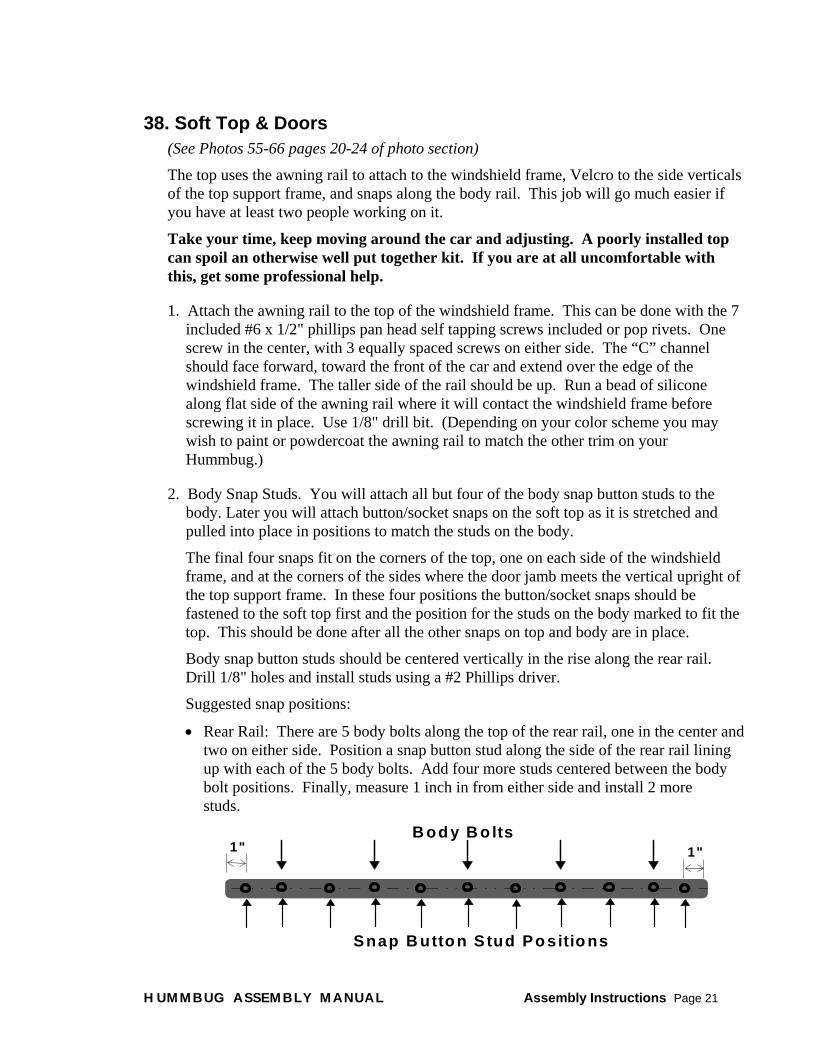
1. Attach the awning rail to the top of the windshield frame. This can be done with the 7 included #6 x 1/2" phillips pan head self tapping screws included or pop rivets. One screw in the center, with 3 equally spaced screws on either side. The “C” channel should face forward, toward the front of the car and extend over the edge of the windshield frame. The taller side of the rail should be up. Run a bead of silicone along flat side of the awning rail where it will contact the windshield frame before screwing it in place. Use 1/8" drill bit. (Depending on your color scheme you may wish to paint or powdercoat the awning rail to match the other trim on your Hummbug.)
2. Body Snap Studs. You will attach all but four of the body snap button studs to the body. Later you will attach button/socket snaps on the soft top as it is stretched and pulled into place in positions to match the studs on the body.
The final four snaps fit on the corners of the top, one on each side of the windshield frame, and at the corners of the sides where the door jamb meets the vertical upright of the top support frame. In these four positions the button/socket snaps should be fastened to the soft top first and the position for the studs on the body marked to fit the top. This should be done after all the other snaps on top and body are in place.
Body snap button studs should be centered vertically in the rise along the rear rail. Drill 1/8" holes and install studs using a #2 Phillips driver.
Suggested snap positions:
• Rear Rail: There are 5 body bolts along the top of the rear rail, one in the center and two on either side. Position a snap button stud along the side of the rear rail lining up with each of the 5 body bolts. Add four more studs centered between the body bolt positions. Finally, measure 1 inch in from either side and install 2 more studs.
B o d y B o lts
Snap B utto n S tud Po sitio ns
1" 1"
HUMMBUG ASSEMBLY MANUAL Assembly Instructions Page 21

• Sides: Starting from the rear, position the first stud 1 inch from the corner. The second stud should be positioned 4” from the first stud. The third stud should be 5 inches from the second. Continue with 6 more studs spacing them 5" apart, going across the sides, and down. The final stud, located generally beneath the vertical support of the top frame will be positioned after all of the other snaps are in position on the body and the soft top.
• Windshield Frame: Position 2 studs on the face of the windshield frame, on either side of the corner. When all of the other snaps are in place you will position a stud on the sides of the frame to match the snap/socket on the soft top.
Final stud willgo about here
3. Rear Bow
• Use the set screws to fasten the nylon eye ends to the legs of the rear bow. Attach the deck mounts to the eye ends. Be sure to position the eye ends so that the deck mounts will lay flat.
• Lay the rear bow (7/8" tubing) on top of the rear passenger rail so that it is flush with the outer edge. Mark the position of the deck mount.
• Remove rear bow, drill holes, and mount deck mount/rear bow to the passenger rail with provided 10-24 x 1-1/4" Phillips Oval Head Self Drilling Screws.
•
4. Soft Top: Slide the top into the awning rail. Center it on the windshield frame. Fold the top over the “C” channel and back over the top support frame...Before installing the top you may wish to install the 4 corner snaps (windshield frame and door jamb button/socket snaps) discussed in part 2. You may also wish to install a button/socket in the center of the rear of the top.
HUMMBUG ASSEMBLY MANUAL Assembly Instructions Page 22

5. Center Bow: The center bow has a saddle on either end that rests on the side bars of the top support frame.
Determine where to position your center bow by locating the Velcro straps on the underside of the soft top. (About halfway between the center bars). The Velcro straps and tension of the top will hold the center bar in place. If you want more security use the pilot holes on the saddle to mark the position on the side bars and secure using the provided #6 x 1/2" Phillips pan head self-tapping screws.
Note: there is no photo of the center bow in the photo section since the center bow was developed after the photos were taken.
6. Install side bar padding. You will need to cut a slit in the pad and cover to allow for the center bow.
7. On the underside of the soft top are velcro straps for both center bars, the center bow and the rear bow. Attach these straps now. The center bar straps are purposely long to allow for the addition of thick bar padding if desired. Foam pipe insulation, 1-3/8" inner diameter, 1/2" thick walls makes a nice padding.
8. Attach self adhesive velcro to the rear of the center legs of the top support frame. Use the top to determine length and position of velcro strips.
9. Soft Top Snaps: You will attach the button & socket pieces of the snaps to the soft top using the punch & die provided in your snap kit. You can rent or borrow a snap-fastening tool for easier installation. It will be easier to smooth and stretch the top into place if you have at least two people working on this. Working in warm weather also makes smoothing the wrinkles out of the top easier.
• Double check that the top is centered in the awning rail, then install snaps at the front of the top to match the studs in the windshield frame.
• Find and mark the rear center of the soft top and install snap. Snap the center snap of the soft top to the center snap on the body. Working from one side of the center to the other stretch and smooth the top and attach snaps to the soft top that correspond with the snaps on the body. Fasten snaps as you go. Alternating sides will help keep wrinkles out of the top. Work from the rear towards the door jamb.
• With all the velcro and snaps fastened in place, stretch and smooth the top to find the position for the final four snap studs, on the door jambs beneath the top frame verticals and on the sides of the windshield frame. Drill and install studs. Fasten snaps.
10. Battens: There are pockets for battens over the door openings. (Use edge molding available at Home Base type stores about 1-1/4" tall, 1/2" thick, you can use wooden or the plastic kind.) Your batten should be at least the length of the top pocket. A longer batten that extends out of the pocket can add stiffness to your top. If you opt for this you may wish to paint the protruding ends of the battens.
11. To Mount Doors:
HUMMBUG ASSEMBLY MANUAL Assembly Instructions Page 23

• Attach hinges to door frames
• Place door frames in body openings. Position frame so the gap between door edge and body is equal.
• Mark hinge to body mount points.
• Drill #6 or #8 pilot hole. Install hinges with provided #10 self-drilling screws.
• With door mounted, install paddle latch in door frame so that the striker correctly engages the tab on the support frame. Cut out the material so that the flange of the paddle latch overlaps the material. Be careful not to cut out too much!
39. Bikini Top Attach the awning rail to the windshield frame, install center bow as per regular soft top.
Slide top into awning rail and center it.
Secure bikini top to top frame using velcro straps along the two center bars and the center bow. Again, the center bar straps are large enough to allow for the addition of 1/2" wall foam pipe insulation as padding and there are pockets for stiffening battens over the doors as in the regular soft top.
Attach plastic clips and buckle to long strap. Install clip anchor deck mounts provided with bikini top on the side rear passenger rail. Use the provided #8 tapping screws. Clip long strap to clip anchor deck mounts and pull straps tight.
40. Apply Patent Protection Sticker The Hummbug is an original design registered with the US Patent and Trademark Office
under D393609.
Please help us protect this design by attaching one of the patent protection stickers (found in the envelope packed in the Hummbug Kit Accessory Box) to your finished Hummbug.
We suggest in the trunk/gas tank area as an accessible but unobtrusive area for the patent sticker.
We appreciate your cooperation.
41. Mount Finish Tires & Wheels
This Product is Patent Protected
D393609 U.S. Patent and Trademark Office
42. Test Drive
HUMMBUG ASSEMBLY MANUAL Assembly Instructions Page 24

Hummbug Assembly Manual
Appendix A: Hummbug Kit Contents
Fiberglass Body, with installed Steel Subframe, Steering Bracket, and Front Splash/Kick Panel. Necessary cutouts
performed, miscellaneous mount points pre-drilled, all post-mold preparation performed, primed & fully 320 sanded.
Hood Windshield Frame with Steel Subframe
Steel Brushguard Front Bumper
Hood Support Rod Mounting Hardware:
Front Bumper Left Side Axle Beam Angle Bracket Front Bumper Right Side Axle Beam Angle Bracket Front Bumper Flat Plate Spacer Brackets (2) Front Bumper Mount Angle Brackets (2) Rear Bumper Mount Tower Bracket Combination Tire Rack Hinge Bracket/Rear Bumper Mount Tower Bracket Tire Rack Pin Bracket
Rear Bumper Tire Rack
Top Support Frame: Left Side Right Side Center Bars (2)
Plastic Defrost Shield
Hummbug Emblems (5)
Headlight Buckets (1 Left & 1 Right)
Heater Vent Doors (1 Left & 1 Right)
Skid Pan
Windshield Hinge Spacer Plates (2)
HUMMBUG ASSEMBLY MANUAL Appendix A: Hummbug Kit Contents Page 1

Lights Amber Front Turn Signals w/gasket & screws (2) Sealed Small Amber Front Marker Lights (2) Sealed Small Red Rear Marker Lights (2) Black Marker Light Mounting Brackets (4) Sealed 2-1/2" Round Amber Rear Turn Signal Light(2) Black Recessed Mount 2-1/2" Grommets for Rear Turn Signal Lights (2) Large Red Stop/Tail Lights w/Black Recessed Mount Grommets (2) Red Reflectors, 2-3/8" Round, w/Self Adhesive Backing (2) Amber Reflectors ,2-3/8" Round, w/Self Adhesive Backing (2) License Bracket w/ Light (includes License Plate Fastener Pkg.) Headlight Switch Emergency Light Toggle Switch Emergency Panel Light
Other Hardware & Parts Black Powdercoat Flush Hood Hinge (Pair: 1 Left Side Pin & 1 Right Side Pin) Black Powdercoat Flush Windshield Hinge (Pair: 1 Left Side Pin & 1 Right Side Pin) Black Textured Vinyl Self-Adhesive Anti-Slip Tape for Running Boards (2 4' x 6" Strips) Black Side Mirrors (1 Left & 1 Right) Extended Brake Hose (1 Meter) Frame to Pan Gasket Grille Decal Kit (18" x 6" Self-Adhesive Black Textured Vinyl and Template) Headlight Rings (2) Rubber Hood Latches (2) Self-Adhesive Natural Rubber Strip (25' x 3/4" x 1/4") for Hood, Windshield to Body,
and Gas Tank Gaskets. Tire Rack Safety Snap Pin Vinyl Coated Steel Battery Tray, Hold Down Frame, & J Bolts Wiper Motors & Wipers (2) Wiring Harness
Nuts & Bolts Assembly Packages Body Front Bumper & Brushguard Hood Lights Miscellaneous Rear Bumper
Tire Rack Top Support Frame Windshield Wiring Harness Wiring Harness (Asstd. Nylon
Clamps)
HUMMBUG ASSEMBLY MANUAL Appendix A: Hummbug Kit Contents Page 2

Paper Assembly Manual–usually mailed separately at time of placing order. Accessory Box Envelope–packed in accessory box shipped with your kit
• Accessory Box Packing List • Detailed Nuts & Bolts List • Wiring Harness Diagram • Manual Addenda–any changes/additions to the manual • Patent Protection Stickers
Invoice–mailed separately after kit is shipped MSO (Manufacturer’s Statement of Origin)–mailed separately after kit is shipped
Deluxe Kit Additions Awning Rail Black Nylon Rear Bow Eye End (2) Black Nylon Rear Bow Deck Mounts (2) Black Powdercoat Flush Door Hinges w/Removable Pins (4) Center Top Support Bow Rear Top Support Bow Self-Adhesive Velcro Strip (6') Side Bar Pads(2) Snap Kit Soft Door Skins installed on Door Frames (2) Soft Top Stainless Steel Paddle Handle Door Latches (2) Soft Top & Door Nut & Bolt Assembly Pkg.
Deluxe Bikini Top Addition Option Uses Soft Top Hardware. Bikini Top Nylon Strap-Clips and Anchors Deluxe Bikini Top Nut & Bolt Assembly Pkg.
Basic Bikini Top Option Awning Rail Bikini Top Center Top Support Bow Nylon Strap-Clips and Anchors Side Bar Pads (2) Basic Bikini Top Nut & Bolt Assembly Pkg.
HUMMBUG ASSEMBLY MANUAL Appendix A: Hummbug Kit Contents Page 3

Other Options
Carpet Kit–Complete coverage, including rear bench & back areas and firewall. Carpet in 15 Pieces
Custom Exhaust System For Use With Baja Header, Not Supplied
Muffler Straight Tail Pipe 2-Bend Primary Exhaust Pipe 1-Bend Secondary Exhaust Pipe Clamps (4) L-Bracket
Rubber Strap Hanger Collector Collector Gasket Collector Gasket Flange Exhaust Nuts & Bolts Assembly Pkg.
Rear Bench & Back–Padded Black Vinyl attaches to carpeted bench/shelf with Velcro strips.
Seat Pad Back Pad
Rear Deck Luggage Rack Luggage Rack Luggage Rack Nuts & Bolts Assembly Pkg.
HUMMBUG ASSEMBLY MANUAL Appendix A: Hummbug Kit Contents Page 4

Hummbug Assembly Manual
Appendix B: Fuel Tank Options The Hummbug kit requires an early style fuel tank with a shortened, and possibly relocated, neck. The simplest thing to do is to buy a new one, already modified, from Vintage Speedsters for $65 plus shipping. (Price at time of writing this manual)
Vintage Speedsters, 12112 Centralia Rd, Hawaiian Gardens, CA 90716 (562)402-4334
Gas Tank Modification We strongly recommend that you do not try to do this yourself. It should be done by a shop that is experienced in welding gas tanks. Any gas tank that has had gasoline in it is potentially dangerous. This is true for all gas tanks.
Before performing any modifications do the following: Drain all gasoline from tank. Fill tank with detergent and water solution. Agitate tank and drain. Refill with soap and water solution, right to the bottom of the filler neck. (Note, even new tanks may have an inside coating of a flammable rust retardant.)
1967 or Older Gas Tanks
For ’67 or older tanks, cut filler neck off flush with tank. With cap still on filler, cut filler neck down just below vent fitting. Weld shortened filler neck back onto tank. Some prefer to relocate the filler to the opposite corner. Cut a plug the size of the filler where you wish
HUMMBUG ASSEMBLY MANUAL Appendix B: Fuel Tank Page 1

the filler to be and weld in the plug to seal the original filler hole. Weld shortened filler neck in the relocated position.
1968 or Newer Gas Tanks
For ’68 or newer tanks, cut the stub off the tank and discard it. Remove the filler neck from the donor body and trim it down to the threads. (Some filler necks must be cut from the body, others are a separate piece.) Place filler neck in the stub opening at an upward angle and weld.
HUMMBUG ASSEMBLY MANUAL Appendix B: Fuel Tank Page 2

Hummbug Assembly Manual
Appendix C: Wiring Harness Schematic
Full Size Diagram Packed in Accessory Box
HUMMBUG ASSEMBLY MANUAL Appendix C: Wiring Harness Page 1

Appendix C: Wiring Harness Schematic Page 2 Full Size Diagram Packed in Accessory Box
HUMMBUG ASSEMBLY MANUAL Appendix C: Wiring Harness Page 2

Appendix C: Wiring Harness Schematic Page 3 Full Size Diagram Packed in Accessory Box
HUMMBUG ASSEMBLY MANUAL Appendix C: Wiring Harness Page 3

Hummbug Assembly Manual
Appendix D: Grill Decal Template Make decals to trim your grill using this template and the
included self-adhesive black textured vinyl.
Glue Diagram to a stiff piece of cardboard. (An old file folder and a glue stick work well.)
Carefully cut out the template
On the paper backing of your self-adhesive black textured vinyl strip trace 7 figures.
Carefully cut and trim
Remove the backing and apply to your clean, painted grill.
Caution! This adhesive is strong. Be sure the decal is in position before it touches the grill.
Dimensions:
5-5/16" tall
2-3/16" wide
1-3/32" radius
(2-3/16" diameter)
Print diagram from keycad. Physically cut & paste.
HUMMBUG ASSEMBLY MANUAL Appendix D: Grill Decal Template Page 1

Hummbug Assembly Manual
Appendix E: Carpet Kit Option
Hummbug Carpet Kit Diagram –15 pieces Install pieces in order indicated using contact cement.
HUMMBUG ASSEMBLY MANUAL Appendix E: Carpet Kit Page 1

Hummbug Assembly Manual
Appendix F: Optional Exhaust System Notes
• Put the collector on the header: (We use Baja exhaust header: Thunderbird #4224 from Autosport: 1-800-344-2847)
• Hang the muffler from the pre-drilled hole in the body sub-frame. The muffler sits on the driver side of the engine, vertically, with a hanger off the back.
• Cut the pipes to fit.
• The primary pipe has a 120 degree bend, and a 20 degree bend. The end of the pipe with the 120 degree bend is expanded to slip over the collector.
• The secondary pipe has a 90 degree bend that has a swedge fit end and a standard end. The swedge end slides over the primary pipe. The standard end goes to the inlet of the muffler and will need to be cut to length. This joint may need to be welded.
• The tail pipe is the straight 12 inch piece, and attaches to the outlet of the muffler.
• Photo #27 on page 10 of the photo section can give you a sense of the positioning of the pipes.
• Make sure the muffler bracket has clearance on the CV boot.
• Make sure there is sufficient clearance between the pipes and the fiberglass body.
• When installing the muffler adjust/rotate it in position to give maximum clearance from the body subframe on one side and the engine valve cover on the other. Leave enough clearance to service the valves.
• We provide clamps for the joints, but welding may be required for a complete seal.
• Chris recommends that you sand lightly and paint black the muffler and exhaust pipes using a paint designed for barbecues. This looks good and helps prevent corrosion.
HUMMBUG ASSEMBLY MANUAL Appendix F: Exhaust System Option Page 1

Hummbug Optional Exhaust System Contents 1 muffler 1 straight tail pipe 1 2-bend primary exhaust pipe 1 1-bend secondary exhaust pipe 4 clamps 1 L-bracket 1 rubber strap hanger 1 collector 1 collector flange 1 collector flange gasket
3 3/8" x 1" hex cap screws (Collector Flange to Header) 3 3/8" nuts 1 5/16" x 1" hex cap screw (L bracket to muffler) 1 5/16" x 1-1/2" hex cap screw (L bracket to rubber strap hanger) 1 5/16" x 2-1/2" hex cap screw (Rubber strap hanger to body sub-frame) 3 5/16" nuts 6 5/16" fender washers
HUMMBUG ASSEMBLY MANUAL Appendix F: Exhaust System Option Page 2

Hummbug Assembly Manual
Appendix G: Rear Deck Luggage Rack
Hummbug Rear Deck Luggage Rack Mounting Instructions The Hummbug rear deck luggage rack mounts by way of threaded inserts in the four legs that rest on the deck.
1. Cover the rear deck with some type of paper or tape that will prevent scratching, and that you can write on to mark locations. (If you get your luggage rack at the same time as your kit, pre-mount it and avoid possible paint problems during drilling.)
2. Place the rack on the deck, visually centering it on the deck lid. Use a straight edge held against the fender to measure from the side to the rack. When you are satisfied with the placement, trace around the leg.
3. Look underneath the deck lid, and confirm your leg placement mount hole will intersect with the body subframe rails that run below the deck lid. The holes do not have to center perfectly on frame rails.
4. Adjust if necessary.
5. Starting with a small bit, drill a hole in the center of your marked circles, then gradually work your way up to a 3/8" diameter hole. Warning–if you increase the diameter too quickly, you risk chipping the fiberglass.
6. Use the supplied bolts, washers to mount. If needed, space between the body and the frame rails by using washers as you did on the rear bumper mounts. Loosely start all the bolts, and then slowly and equally tighten.
We’ve included both self adhesive rubber strip that can be cut to fit and four rubber washers, either of which can be used to cushion between the mounting feet and the body.. Use whichever you prefer. We are still looking for the perfect rubber washer.
Rear Deck Luggage Rack Option Contents Luggage Rack
3/8"-16 x 2-1/2" Hex Cap Screws, Zinc (4)
3/8" Flat Washers, Zinc (16)
7/16" x 3/4" x 3/32" Rubber Washers (4)
1" x 1/8" Natural Rubber Self-Adhesive Strip (6 inches)
HUMMBUG ASSEMBLY MANUAL Appendix G: Luggage Rack Page 1

Hummbug™ Assembly Manual
Appendix H: Trannys, Tires, & Engines Depending on your choice of engine, tire size, and year of donor transmission, you may need to exchange the transmission for one with a different ring and pinion for proper performance. Please consult a competent VW mechanic to assist in this decision. Taller than stock tires change the effective gear ratio of the transmission. To maintain equivalent performance the gear ratio in the transmission must be lowered and/or the engine power output increased as tire height is increased. Pre-1968 swing axle transmissions have a 4.37 ring & pinion. IRS transmissions 1968-‘72 have a 4.12 RP, 1973 and later have a 3.88 RP. Re-built transmissions are readily available with your choice of ring and pinion for around $300.00. Our prototype used a 1973 chassis with its original 3.88 RP IRS transmission, a 1776 cc, dual carbureted performance engine, and 29" tall Mickey Thompson tires. The higher horse power engine compensated for the 3.88 RP and tall tires providing adequate power and acceleration. When using a stock 1600 cc engine with anything taller than a stock tire we prefer a 4.37 RP transmission. Our current shop demo is a 1973 chassis, using the original stock single carburetor 1600 cc dual port engine and P235 75 R15 traction tires. The original 3.88 RP ’73 transmission with this engine and tire combination performed terribly. We swapped it for a rebuilt 4.37RP transmission which solved most of the problem. It could still use a little more power in fourth gear. We could do this by either installing a custom close ratio fourth gear or upgrading the engine. The correct matching of engine, transmission and tires is a science. Please consult a professional.
Formulae courtesy of Oregon Performance Products
PO Box 1715 Hillsboro, OR 97123
(503) 628-3409 http//www.spiretech.com/~opshroud
Performance Formulae Factors That Must Be Known 1. Engine RPM (Revolutions per Minute) 2. Tire Radius in Inches (Tire Diameter divided by 2) 3. Ring and Pinion Ratio 4. Transmission Gear Ratio 5. Final Ratio = (Ring & Pinion Ratio x Transmission Gear Ratio) 6. Constant = 168 7. M.P.H. (Miles per Hour)
Formula to Determine MPH: MPH = (RPM x Tire Radius) / (Final Ratio x 168)
Example: (4400 RPM x 16 inches) / {(4.59 x .88) x 168} = 70,400 / 675.36 = 104.2 MPH
Formula to Determine Cruising RPM RPM = (MPH X Final Ratio x 168) / Tire Radius
Example: (65 MPH x (4/57 x .88) x 168) / 16 inches=43,898 / 16 = 2,743.6 RPM
Formula to Determine RPM Change when Shifting Up or Down: (Present RPM / Present Transmission Gear Ratio) x Next Gear Ratio = New RPM
Example A, Shifting from 2nd (2.06) to 3rd (1.26) @ 4,400 RPM (4400 / 2.06) x 1.26 = 2,135 x 1.26 = 2,691 RPM, a 1,709 RPM Drop.
HUMMBUG™ ASSEMBLY MANUAL Appendix H: Trannys, Tires & Engines Page 1

Example B, Shifting from 4th (.88) to 3rd(1.26) @ 2,500 RPM (2500 / .88) x 1.26 = 2,840 x 1.26 = 3,579 RPM, a 1,079 RPM Rise.
Some HUMMBUG™ Customers have found this company to be quite helpful with their transmission decisions:
Transform Company 800-508-7267 Phone 2105 Cowles Street 562-435-2966 Fax Long Beach, CA 90813
Mail $3.00 for a catalog. See their ad in Hot VWs.
Quote from TRANSFORM COMPANY catalog:
Ever wonder why your Baja Bug, Thing, Manx, or Street Rail never has the power it should? Gets poor mileage? Suffers early engine failure? The answer is simple. When you installed those tall (27" to 33") tires, the effective gear ratios in the transaxle were changed dramatically. The stock ratios, so carefully chosen by the factory to optimize the VW engine, are now working against you. Big Time. The combination of bad ratios and greater wheel/tire moment of inertia commonly results in a 25% loss of power when the same bad ratios that kill performance also hurt mileage and engine life.
Fortunately, excellent performance is available with a well-planned change of ratios. At TRANSFORM we specialize in Baja ratios and take pride in providing effective, affordable solutions. We will take the time to analyze your exact needs, as these vary greatly with type of vehicle, terrain, tire diameter, etc. (please measure from ground to top of tire before you call.) Prices start as just $299. Look at it this way: the transaxle will pay for itself with added mileage and engine life. The great performance is free! All have great freeway drivability. NOW ON SALE!
Price Ring 3rd 4th Comment
Baja #1 $299 4.37 1.26 .93 Great for shorter (26"-28") tires and/or small budgets.
Baja #2 $379 4.37 or 4.12 1.32 1.00 or 1.04 Low cost choice if freeway rpm is the problem.
Baja #3 $469 4.37 or 4.12 1.48 1.04 If stock 1st & 2nd ratios are OK , you win big in 3rd & 4th.
Baja #4 $489 4.86 1.32 .89 When more rpm is needed in 1st & 2nd as well as 3rd & 4th.
HUMMBUG™ ASSEMBLY MANUAL Appendix H: Trannys, Tires & Engines Page 2

Hummbug Assembly Manual
Appendix I: Sample MSO, Manufacturer’s Statement of Origin
An MSO is provided with each kit. Sample front page..
HUMMBUG ASSEMBLY MANUAL Appendix I: Sample MSO Page 1

Appendix I: Sample MSO, Page 2 Manufacturer’s Statement of Origin, sample back page.
HUMMBUG ASSEMBLY MANUAL Appendix I: Sample MSO Page 2

Hummbug Kit Nuts & Bolts Assembly Package Contents
BATTERY TRAY Position Item Qty Battery Tray to Body Subframe 5/16"-18 x 2" Hex Cap Screw Zinc 2 Battery Tray to Body Subframe 5/16"-18 Nylon Insert Lock Nut Zinc 2 Battery Tray to Body Subframe 5/16" USS Flat Washer Zinc 4 Battery Tray to Body Subframe 5/16" x 1" Fender Washer Zinc 2
BODY Position Item Qty Frame to Chassis 3/8"-16 x 2" Hex Cap Screw Zinc 4 Frame to Chassis 3/8"-16 Nylon Insert Lock Nut Zinc 4 Frame to Chassis 3/8" USS Flat Washer Zinc 8 Frame to Pan 5/16"-18 x 1-1/4" Fully Threaded Carriage Screw Zinc 10 Frame to Pan 5/16"-18 Nylon Insert Lock Nut Zinc 10 Frame to Pan 5/16" x 1-1/4" Fender Washer Zinc 10
FRONT BUMPER & BRUSHGUARD Position Item Qty Axle Beam Bracket to Axle Beam 12mm x 100mm 1.50 pitch Hex Cap Bolt 4 Brush Guard to Body 3/8" USS Flat Washer Zinc 4 Brush Guard to Body 3/8"-24 x 1" Hex Cap Screw Zinc 2 Brush Guard to Bumper 5/16" USS Flat Washer Zinc 4 Brush Guard to Bumper 5/16"-18 x 1" Hex Cap Screw Zinc 4 Brush Guard to Bumper 5/16"-18 Nylon Insert Lock Nut Zinc 4 Front Bumper Bracket Assembly 3/8" USS Flat Washer Zinc 12 Front Bumper Bracket Assembly 3/8"-16 x 1" Hex Cap Screw Zinc 12 Front Bumper Bracket Assembly 3/8"-16 Nylon Insert Lock Nut Zinc 12 Front Bumper to Body 5/16" USS Flat Washer Zinc 4 Front Bumper to Body 5/16"-18 x 1" Hex Cap Screw Zinc 4 Front Bumper to Body 5/16"-18 Nylon Insert Lock Nut Zinc 4 Skid Pan to Bumper #10 x 1/2" Hex Head Tap Screw Zinc 2
HOOD Position Item Qty Hood Hinge to Body #10 Flat Washer SS 6 Hood Hinge to Body #10-24 Nylon Insert Lock Nut SS 6 Hood Hinge to Body #10-24 x 1" Phillips Oval Head Machine Screw SS 6 Hood Hinge to Hood #10 Flat Washer SS 6 Hood Hinge to Hood #10-24 Nylon Insert Lock Nut SS 6 Hood Hinge to Hood #10-24 x 3/4" Phillips Oval Head Machine Screw SS 6
HUMMBUG ASSEMBLY MANUAL Nuts & Bolts by Assembly Page 1

HOOD (Continued) Position Item Qty Rubber Hood Latch to Body #10 Flat Washer SS 2 Rubber Hood Latch to Body #10-24 x 3/4" Phillips Pan Head Machine Screw SS 2 Rubber Hood Latch to Hood #10 Flat Washer SS 4 Rubber Hood Latch to Hood #10-24 x 3/4" Phillips Pan Head Machine Screw SS 4 Hood Support Rod 1/4" Flat Washer Zinc 2 Hood Support Rod 1/4"-20 Nylon Insert Lock Nut Zinc 2 Hood Support Rod 1/4" Plastic End Cap 1
LIGHTS Position Item Qty Front Turn Signal Base to Body #6 x 1/2" Phillips Pan Head Self Tapping Screw Zinc 8 Headlight Bucket to Body 1/4"-20 x 1-1/4" Pan Head Phillips Machine Screw SS 8 Headlight Bucket to Body 1/4" Flat Washer SS 8 Headlight Bucket to Body 1/4" Nylon Insert Lock Nut SS 8 Headlight Ring to Bucket #8-32 x 3/8" Pan Head Phillips Swageform Screw SS 6 License Bracket w/Light to Rear Bumper #10-24 x 1/2" Phillips Pan Head Machine Screw SS 2 License Bracket w/Light to Rear Bumper #10-24 Nylon Insert Lock Nut SS 2
MISCELLANEOUS Position Item Qty Defrost Shield to Dash #6 x 1/2" Phillips Pan Head Self Tapping Screw Zinc 5 Heater Vent Door Plates #6 x 1/2" Phillips Pan Head Self Tapping Screw Zinc 8 Side Mirrors to Body #10-16 x 1-1/4" Phillips Oval Head Self Drilling Screw, Zinc 4 Wiper Motors to Dash #10 x 3/4" Phillips Pan Head Self Tapping Screw Zinc 2
REAR BUMPER Position Item Qty Rear Bumper to Mount Bracket 3/8"-16 x 1" Hex Cap Screw Zinc 4 Rear Bumper to Mount Bracket 3/8"-16 Nylon Insert Lock Nut Zinc 4 Rear Bumper to Mount Bracket 3/8" USS Flat Washer Zinc 8 Rear Bumper Mount Bracket to Body 3/8"-16 x 1-1/2" Hex Cap Screw Zinc 8 Rear Bumper Mount Bracket to Body 3/8"-16 Nylon Insert Lock Nut Zinc 8 Rear Bumper Mount Bracket to Body 3/8" Flat Washer Zinc 16
TIRE RACK Position Item Qty Hinge Bracket to Body 3/8" USS Flat Washer Zinc 4 Hinge Bracket to Body 3/8"-16 x 2-1/2" Hex Cap Screw Zinc 2 Hinge Bracket to Body 3/8"-16 Nylon Insert Lock Nut Zinc 2 Hinge Bracket to Body, 3/8" USS Flat Washer Zinc 10 (Body to Subframe support spacers)
Pin Bracket to Body 3/8" USS Flat Washer Zinc 4 Pin Bracket to Body 3/8"-16 x 2-1/2" Hex Cap Screw Zinc 2
HUMMBUG ASSEMBLY MANUAL Nuts & Bolts by Assembly Page 2

TIRE RACK (Continued) Position Item Qty Pin Bracket to Body 3/8"-16 Nylon Insert Lock Nut Zinc 2 Pin Bracket to Body, 3/8" USS Flat Washer Zinc 10 (Body to Subframe support spacers)
Tire Rack to Hinge Bracket 3/8" Flat Washer SS 8 Tire Rack to Hinge Bracket 3/8"-16 x 2-1/4" Hex Cap Screw SS 2 Tire Rack to Hinge Bracket 3/8"-16 Nylon Insert Lock Nut SS 2
TOP SUPPORT FRAME Position Item Qty Top Support Frame Front to Body 5/16"-18 x 3" Hex Head Cap Screw, Zinc Grade 8 4 Top Support Frame Rear to Body 5/16"-18 x 3-3/4" Hex Head Cap Screw, Zinc Grade 8 4 Top Support Frame Center to Body 5/16"-18 x 7" Hex Head Cap Screw, Grade 8 4 Top Support Frame to Body 5/16"-18 Nylon Insert Lock Nut, Zinc Grade 8 12 Top Support Frame to Body 5/16" USS Flat Washer Zinc 12 Top Support Center Bars to Sides #8 x 1/2" Unslotted Hex Washer Head Self Drilling Screws 8 Top Support Frame to Windshield 1/4"-20 x 2-1/2" Carriage Screw SS 2 Top Support Frame to Windshield 1/4" Flat Washer SS 2 Top Support Frame to Windshield 1/4"-20 Nylon Insert Lock Nut SS 2
WINDSHIELD Position Item Qty Windshield Hinge to Body #10 Flat Washer SS 6 Windshield Hinge to Body #10-24 Nylon Insert Lock Nut SS 6 Windshield Hinge to Body #10-24 x 1-1/2" Phillips Oval Head Machine Screw SS 6 Windshield Hinge to Frame #10 Flat Washer SS 6 Windshield Hinge to Frame #10-24 Nylon Insert Lock Nut SS 6 Windshield Hinge to Frame #10-24 x 2" Phillips Oval Head Machine Screw SS 6
WIRING HARNESS Position Item Qty Harness to Body Subframe #10 x 1/2" Unslotted Hex Washer Head Self Drilling Screws 20 Front Trunk #10 Flat Washer SS 8 Front Trunk #10-24 Nylon Insert Lock Nut SS 8 Front Trunk #10-24 x 3/4" Phillips Pan Head Machine Screw SS 8 Fuse Box to Fire Wall #6-32 x 5/8" Phillips Pan Head Machine Screw SS 2 Fuse Box to Fire Wall #6-32 Nylon Insert Lock Nut SS 2 Fuse Box to Fire Wall #6 Flat Washer SS 2 Ground Screw in Fire Wall 5/16-18 x 1" Hex Cap Screw Zinc 1 Ground Screw in Fire Wall 5/16-18 x 1" Hex Nut Zinc 1 Ground Screw in Fire Wall 5/16" Flat Washer Zinc 2
HUMMBUG ASSEMBLY MANUAL Nuts & Bolts by Assembly Page 3

WIRING HARNESS (ASSTD. NYLON CLAMPS) Position Item Qty As needed 3/4" Nylon Cable Clamp 2 As needed 5/8" Nylon Cable Clamp 5 As needed 1/2" Nylon Cable Clamp 7 As needed 7/16" Nylon Cable Clamp 5 As needed 3/8" Nylon Cable Clamp 4 As needed 5/16" Nylon Cable Clamp 7 As needed 1/4" Nylon Cable Clamp 2 As needed 5-3/4" Nylon Cable Tie 4
SOFT TOP & DOOR OPTION Position Item Qty Center Bow to Top Support Bars #6 x 1/2" Phillips Pan Head Self Tapping Screw, Zinc 4 Rear Bow Deck Mount to Body #10-16 x 1-1/4" Phillips Oval Head Self Drilling Screw, Zinc 4 Door Hinge to Body #10-16 x 1-1/4" Phillips Oval Head Self Drilling Screw, Zinc 12 Door Hinge to Door #10-24 x 5/8" Phillips Oval Head Machine Screw SS 12 Door Hinge to Door #10 Flat Washer SS 12 Door Hinge to Door #10-24 Nylon Insert Lock Nut SS 12 Paddle Latch to Door #10-24 x 1/2" Phillips Pan Head Machine Screw SS 8 Paddle Latch to Door #10 Flat Washer SS 8 Paddle Latch to Door #10-24 Nylon Insert Lock Nut SS 8 Awning Rail to Windshield Frame #6 x 1/2" Phillips Pan Head Self Tapping Screw, Zinc 7
DELUXE BIKINI TOP ADDITION OPTION Position Item Qty Clip Anchor to Body #8-18 x 1-1/4" Phillips Oval Head Self Drilling Screw, Zinc 4
BASIC BIKINI TOP OPTION Position Item Qty Center Bow to Top Support Bars #6 x 1/2" Phillips Pan Head Self Tapping Screw, Zinc 4 Awning Rail to Windshield Frame #6 x 1/2" Phillips Pan Head Self Tapping Screw, Zinc 7 Clip Anchor to Body #8-18 x 1-1/4" Phillips Oval Head Self Drilling Screw, Zinc 4
CUSTOM EXHAUST OPTION Position Item Qty Collector Flange to Header 3/8" x 1" Hex Cap Screw, Zinc 3 Collector Flange to Header 3/8" Hex Nut, Zinc 3 L-Bracket to Rubber Strap Hanger 5/16" x 1-1/2" Hex Cap Screw, Zinc 1 L-Bracket to Rubber Strap Hanger 5/16" Hex Nut, Zinc 1 L-Bracket to Rubber Strap Hanger 5/16" x 1-1/4" Fender Washer, Zinc 2 Muffler to L-Bracket 5/16" x 1" Hex Cap Screw, Zinc 1 Muffler to L-Bracket 5/16" Hex Nut, Zinc 1 Muffler to L-Bracket 5/16" x 1-1/4" Fender Washer, Zinc 2 Rubber Strap Hanger to Body Sub-Frame 5/16" x 2-1/2" Hex Cap Screw, Zinc 1 Rubber Strap Hanger to Body Sub-Frame 5/16" Hex Nut, Zinc 1 Rubber Strap Hanger to Body Sub-Frame 5/16" x 1-1/4" Fender Washer, Zinc 2
HUMMBUG ASSEMBLY MANUAL Nuts & Bolts by Assembly Page 4

REAR DECK LUGGAGE RACK OPTION Position Item Qty Post to Body 3/8"-16 x 2 -1/2" Hex Cap Screw, Zinc 4 Screw to Body 3/8" USS Flat Washer, Zinc 4 Body to Subframe Spacers 3/8" USS Flat Washer, Zinc 12 Post to Body 6" x 1" x 1/8" Strip Rubber Gasket, trim to fit 1 Post to Body 7/16" x 3/4" x 3/32" Rubber Washers 4
HUMMBUG ASSEMBLY MANUAL Nuts & Bolts by Assembly Page 5