Hughes 9211 User Guide · Hughes 9211 and 9202M User Guide 3500988-0001 Revision D ......
93
Hughes 9211 and 9202M User Guide 3500988-0001 Revision D 12 October 2017
Transcript of Hughes 9211 User Guide · Hughes 9211 and 9202M User Guide 3500988-0001 Revision D ......
Hughes 9211 and 9202M
User Guide
3500988-0001
Revision D
12 October 2017
Copyright © 2014 - 2017 Hughes Network Systems, LLC
All rights reserved. This publication and its contents are proprietary to Hughes Network Systems, LLC. No part of this publication may be reproduced in any form or by any means without the written permission of Hughes Network Systems, LLC, 11717 Exploration Lane, Germantown, Maryland 20876.
Hughes Network Systems, LLC has made every effort to ensure the correctness and completeness of the material in this document. Hughes Network Systems, LLC shall not be liable for errors contained herein. The information in this document is subject to change without notice. Hughes Network Systems, LLC makes no warranty of any kind with regard to this material, including, but not limited to, the implied warranties of merchantability and fitness for a particular purpose.
Trademarks
Hughes and Hughes Network Systems are trademarks of Hughes Network Systems, LLC. All other trademarks are the property of their respective owners.
Contents 3500988-0001 Revision D
iii
Contents
Messages concerning personal injury ...................................................................................................... vii
Messages concerning property damage ................................................................................................... vii
Introduction ................................................................................................................................ 1
Overview .................................................................................................................................................... 1
About this User Guide ............................................................................................................................... 2
9211 Package Contents .............................................................................................................................. 3
9202M Package Contents .......................................................................................................................... 5
Minimum System Requirements for Laptop/PC ........................................................................................ 5
Getting Started ........................................................................................................................................... 5
Information for Maintenance ..................................................................................................................... 6
Date of Manufacture .................................................................................................................................. 6
Manufacturer Contact ................................................................................................................................ 6
Using the Terminal .................................................................................................................... 7
Setup .......................................................................................................................................................... 7
LCD Quick Start ........................................................................................................................................ 8
Web UI Quick Start................................................................................................................................ 9
Connecting the terminal to the computer ................................................................................................. 12
Connecting by Ethernet ........................................................................................................................ 12
Connecting by WLAN ......................................................................................................................... 12
WLAN Security ............................................................................................................................... 13
Connecting by RJ11 ............................................................................................................................. 14
Dialing and Numbering ........................................................................................................................ 15
External Antenna.................................................................................................................................. 15
Coverage Map .......................................................................................................................................... 16
Operation in the I-4 MEAS footprint ................................................................................................... 16
Operation in the Russian Federation .................................................................................................... 17
Using the LCD and Keypad .................................................................................................... 18
LCD Display and Keypad ........................................................................................................................ 18
Terminal Buttons ..................................................................................................................................... 18
LCD Status Display ................................................................................................................................. 19
Pointing mode display .......................................................................................................................... 19
Audible pointing indicator ................................................................................................................... 19
Exit Pointing and Registering with the network .................................................................................. 20
Idle mode display ................................................................................................................................. 20
Connection mode display ..................................................................................................................... 20
Status messages .................................................................................................................................... 21
Menu Navigation ..................................................................................................................................... 22
Display Icons ........................................................................................................................................... 24
Battery Icon .......................................................................................................................................... 24
iv Contents 3500988-0001 Revision D
Power Icon ........................................................................................................................................... 24
GPS Icon .............................................................................................................................................. 24
Satellite Icons ....................................................................................................................................... 25
Wireless LAN Icon .............................................................................................................................. 25
Wireless LAN Lock Icon ..................................................................................................................... 25
Globe ICON ......................................................................................................................................... 25
SIM PIN entry .......................................................................................................................................... 26
Multiple Users .......................................................................................................................................... 26
Information Messages .............................................................................................................................. 26
Using the Web UI ..................................................................................................................... 28
Accessing the Web UI ............................................................................................................................. 28
Home page ............................................................................................................................................... 29
Connections.............................................................................................................................................. 31
Manage Contexts.................................................................................................................................. 32
Automatic Contexts.............................................................................................................................. 34
Manage APNs ...................................................................................................................................... 37
SMS ......................................................................................................................................................... 40
Send/Receive ........................................................................................................................................ 40
Saved Drafts ......................................................................................................................................... 41
Sent Messages ...................................................................................................................................... 42
SMS Settings ........................................................................................................................................ 43
Settings page ............................................................................................................................................ 44
General Setup ....................................................................................................................................... 44
IP Address/DHCP Settings .................................................................................................................. 45
Nat Mode .......................................................................................................................................... 46
Relay Mode ...................................................................................................................................... 47
NAPT Mode ......................................................................................................................................... 47
PPPoE Mode ........................................................................................................................................ 47
Port Forwarding Page........................................................................................................................... 49
Wireless LAN ...................................................................................................................................... 50
Wireless LAN Security ........................................................................................................................ 51
Telephony ............................................................................................................................................ 53
Security ................................................................................................................................................ 54
Features ................................................................................................................................................ 56
M2M Page ................................................................................................................................................ 57
Ping Configuration: .......................................................................................................................... 57
Usage Page ............................................................................................................................................... 59
Support Page ............................................................................................................................................ 60
Support and Information ...................................................................................................................... 61
Operation with Tracking Antenna ......................................................................................... 63
Overview .................................................................................................................................................. 63
Web UI Changes ...................................................................................................................................... 64
C10D Antenna Kit for 9211 and 9202M: 3501057-0001 ........................................................................ 65
C11D Antenna Kit for 9211 and 9202M: 3501058-0001 ........................................................................ 65
Contents 3500988-0001 Revision D
Troubleshooting ....................................................................................................................... 66
Technology Overview .............................................................................................................. 69
GPS .......................................................................................................................................................... 69
Obtaining a GPS Fix ............................................................................................................................ 69
GPS and BGAN Registration ............................................................................................................... 70
Dialing and Numbering ........................................................................................................................ 70
PDP Context............................................................................................................................................. 70
Technical Specifications .......................................................................................................... 72
9211 EU Declaration of Conformity ....................................................................................... 73
FCC Compliance ...................................................................................................................................... 74
EU RoHS-2 (Restriction of Hazardous Substances) Directive ................................................................ 75
EU WEEE (Waste Electrical and Electronic Equipment) Directives ...................................................... 75
Glossary .................................................................................................................................... 76
Application Note – Phone/Fax ................................................................................................ 79
Application Note – Battery ...................................................................................................... 81
Application Note – Battery Safety .......................................................................................... 82
Safety Information ................................................................................................................................... 82
Charging ................................................................................................................................................... 82
Disposal ................................................................................................................................................... 83

vi Tables 3500988-0001 Revision D
Tables
Table 1: Status Messages ......................................................................................................................... 21
Table 2: LCD Menu Structure ................................................................................................................. 23
Table 3: Quick-text Status Message Descriptions ................................................................................... 27
Safety 3500988-0001 Revision D
vii
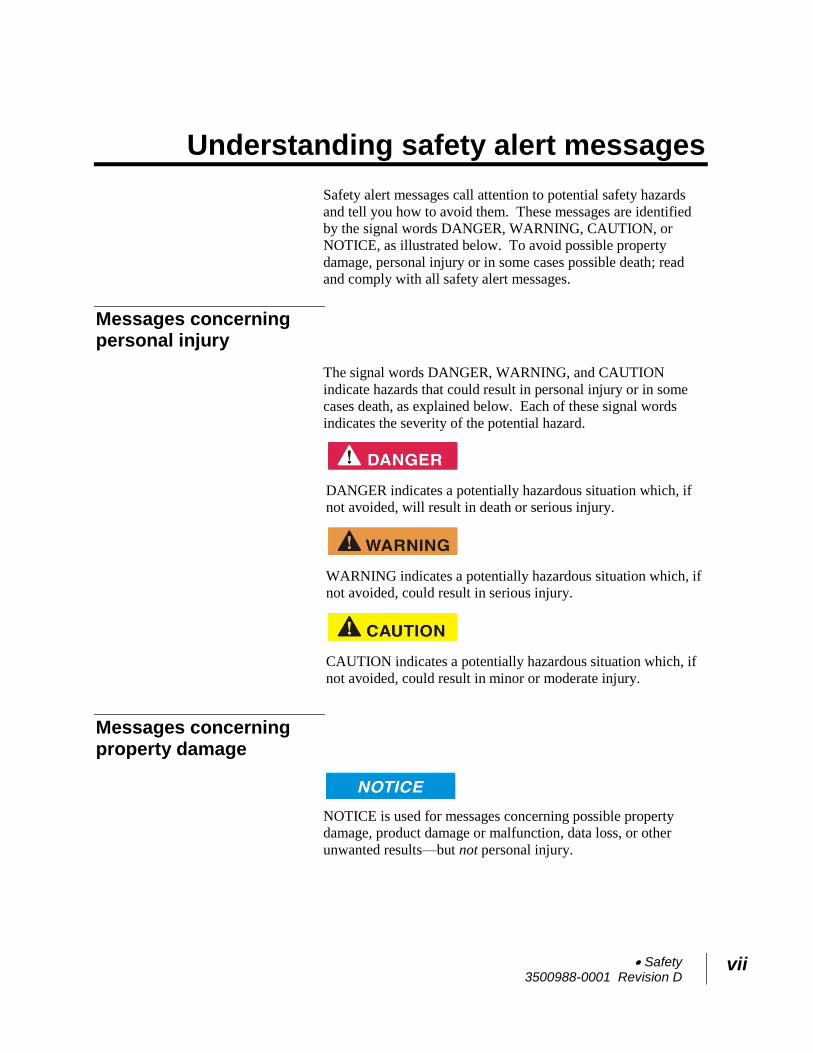
Understanding safety alert messages
Safety alert messages call attention to potential safety hazards
and tell you how to avoid them. These messages are identified
by the signal words DANGER, WARNING, CAUTION, or
NOTICE, as illustrated below. To avoid possible property
damage, personal injury or in some cases possible death; read
and comply with all safety alert messages.
Messages concerning personal injury
The signal words DANGER, WARNING, and CAUTION
indicate hazards that could result in personal injury or in some
cases death, as explained below. Each of these signal words
indicates the severity of the potential hazard.
DANGER indicates a potentially hazardous situation which, if
not avoided, will result in death or serious injury.
WARNING indicates a potentially hazardous situation which, if
not avoided, could result in serious injury.
CAUTION indicates a potentially hazardous situation which, if
not avoided, could result in minor or moderate injury.
Messages concerning property damage
NOTICE is used for messages concerning possible property
damage, product damage or malfunction, data loss, or other
unwanted results—but not personal injury.
viii Safety 3500988-0001 Revision D
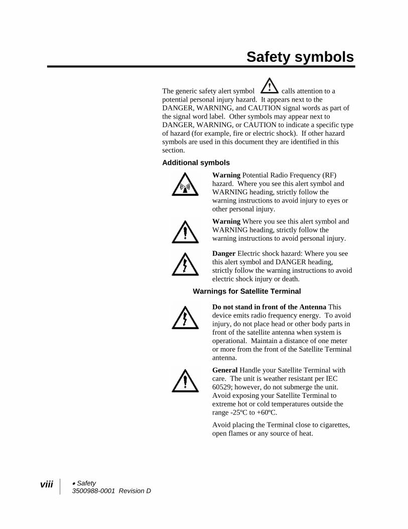
Safety symbols
The generic safety alert symbol calls attention to a
potential personal injury hazard. It appears next to the
DANGER, WARNING, and CAUTION signal words as part of
the signal word label. Other symbols may appear next to
DANGER, WARNING, or CAUTION to indicate a specific type
of hazard (for example, fire or electric shock). If other hazard
symbols are used in this document they are identified in this
section.
Additional symbols
Warning Potential Radio Frequency (RF)
hazard. Where you see this alert symbol and
WARNING heading, strictly follow the
warning instructions to avoid injury to eyes or
other personal injury.
Warning Where you see this alert symbol and
WARNING heading, strictly follow the
warning instructions to avoid personal injury.
Danger Electric shock hazard: Where you see
this alert symbol and DANGER heading,
strictly follow the warning instructions to avoid
electric shock injury or death.
Warnings for Satellite Terminal
Do not stand in front of the Antenna This
device emits radio frequency energy. To avoid
injury, do not place head or other body parts in
front of the satellite antenna when system is
operational. Maintain a distance of one meter
or more from the front of the Satellite Terminal
antenna.
General Handle your Satellite Terminal with
care. The unit is weather resistant per IEC
60529; however, do not submerge the unit.
Avoid exposing your Satellite Terminal to
extreme hot or cold temperatures outside the
range -25ºC to +60ºC.
Avoid placing the Terminal close to cigarettes,
open flames or any source of heat.
Safety 3500988-0001 Revision D
ix
Changes or modifications to the Terminal not
expressly approved by Hughes Network
Systems could void your authority to operate
this equipment.
Only use a soft damp cloth to clean the
Terminal.
To avoid impaired Terminal performance,
please ensure the unit’s antenna is not damaged
or covered with foreign material like paint or
labeling.
When inserting the SIM, do not bend it or
damage the contacts in any way. When
connecting the interface cables, do not use
excessive force.
In the vicinity of blasting work and in
explosive environments Never use the Satellite
Terminal where blasting work is in progress.
Observe all restrictions and follow any
regulations or rules. Areas with a potentially
explosive environment are often, but not
always, clearly marked. Do not use the
Terminal while at a petrol filling station. Do
not use near fuel or chemicals.
Qualified Service Do not attempt to
disassemble your Satellite Terminal. The unit
does not contain consumer-serviceable
components. Only qualified service personnel
may install or repair equipment.
Accessories Use Hughes approved accessories
only. Use of non-approved accessories may
result in loss of performance, damage to the
Satellite Terminal, fire, electric shock or injury.
Battery Use only a battery approved by
Hughes. Risk of explosion if battery is replaced
by an incorrect type. Dispose of used batteries
according to the instructions.
Connecting Devices Never connect
incompatible devices to the Satellite Terminal.
When connecting the Satellite Terminal to any
other device, read the device’s User Manual for
detailed safety instructions.
x Safety 3500988-0001 Revision D
Pacemakers The various brands and models of
cardiac pacemakers available exhibit a wide range
of immunity levels to radio signals. Therefore,
people who wear a cardiac pacemaker and who
want to use a Satellite Terminal should seek the
advice of their cardiologist. If, as a pacemaker
user, you are still concerned about interaction with
the Satellite Terminal, we suggest you follow
these guidelines:
Maintain a distance of one meter from the
main antenna front and sides and your
pacemaker;
Refer to your pacemaker product literature
for information on your particular device.
If you have any reason to suspect that interference
is taking place, turn off your Satellite Terminal
immediately.
Hearing Aids Most new models of hearing aids
are immune to radio frequency interference from
Satellite Terminals that are more than 2 meters
away. Many types of older hearing aids may be
susceptible to interference, making it very difficult
to use them near a Terminal. Should interference
be experienced, maintain additional separation
between you and the Satellite Terminal.
Electrical Storms Operation of the Satellite
Terminal during electrical storms may result in
severe personal injury or death
Introduction 3500988-0001 Revision D
1
Introduction
Overview
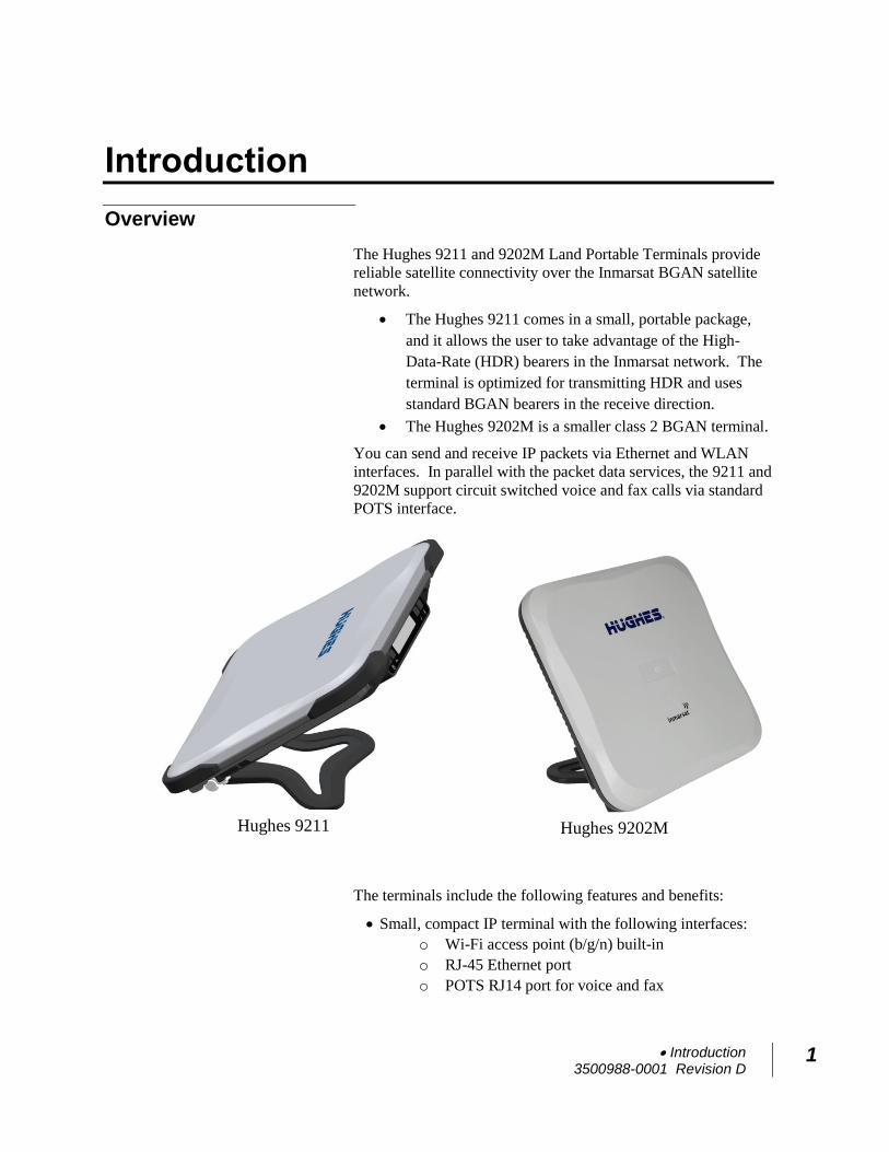
The Hughes 9211 and 9202M Land Portable Terminals provide
reliable satellite connectivity over the Inmarsat BGAN satellite
network.
The Hughes 9211 comes in a small, portable package,
and it allows the user to take advantage of the High-
Data-Rate (HDR) bearers in the Inmarsat network. The
terminal is optimized for transmitting HDR and uses
standard BGAN bearers in the receive direction.
The Hughes 9202M is a smaller class 2 BGAN terminal.
You can send and receive IP packets via Ethernet and WLAN
interfaces. In parallel with the packet data services, the 9211 and
9202M support circuit switched voice and fax calls via standard
POTS interface.
The terminals include the following features and benefits:
Small, compact IP terminal with the following interfaces:
o Wi-Fi access point (b/g/n) built-in
o RJ-45 Ethernet port
o POTS RJ14 port for voice and fax
Hughes 9211 Hughes 9202M
2 Introduction 3500988-0001 Revision D
o External Active Antenna port
SMS Remote Control, with over-air software upgrades
Fully compatible with Remote Terminal Manager (RTM)
Multi-user capability for sharing a single unit
Selectable Quality-of-Service (QoS) up to HDR streaming
(HDR, 9211 only)
Full IP compatibility for Email, file transfer (FTP),
browsing, VPN, etc.
Cost-effective “always-on” access – charges only for data
sent and received
UMTS IP-based services
FCC and CE certified
Subscriber Identification Module (SIM) card security
In this document, the following names and abbreviations are
used to identify the Satellite Terminal and your computer.
Term Definition
Terminal Satellite Terminal
TE Terminal Equipment (your computer)
UT User Terminal/satellite terminal
About this User Guide
This user guide contains the most up-to-date information
available on this product, on the date it was generated. It is
focused on the specific information needed to operate the
Hughes 9211 and 9202M Land Portable Terminals.
For information on using LaunchPad, please refer to the
Inmarsat website where a copy of the ‘Inmarsat LaunchPad
Guide’ can be downloaded: www.inmarsat.com/support
LaunchPad currently does not support the 9202M.
Introduction 3500988-0001 Revision D
3
9211 Package Contents
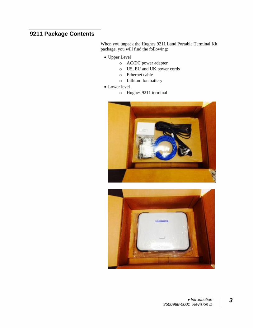
When you unpack the Hughes 9211 Land Portable Terminal Kit
package, you will find the following:
Upper Level
o AC/DC power adapter
o US, EU and UK power cords
o Ethernet cable
o Lithium Ion battery
Lower level
o Hughes 9211 terminal
4 Introduction 3500988-0001 Revision D
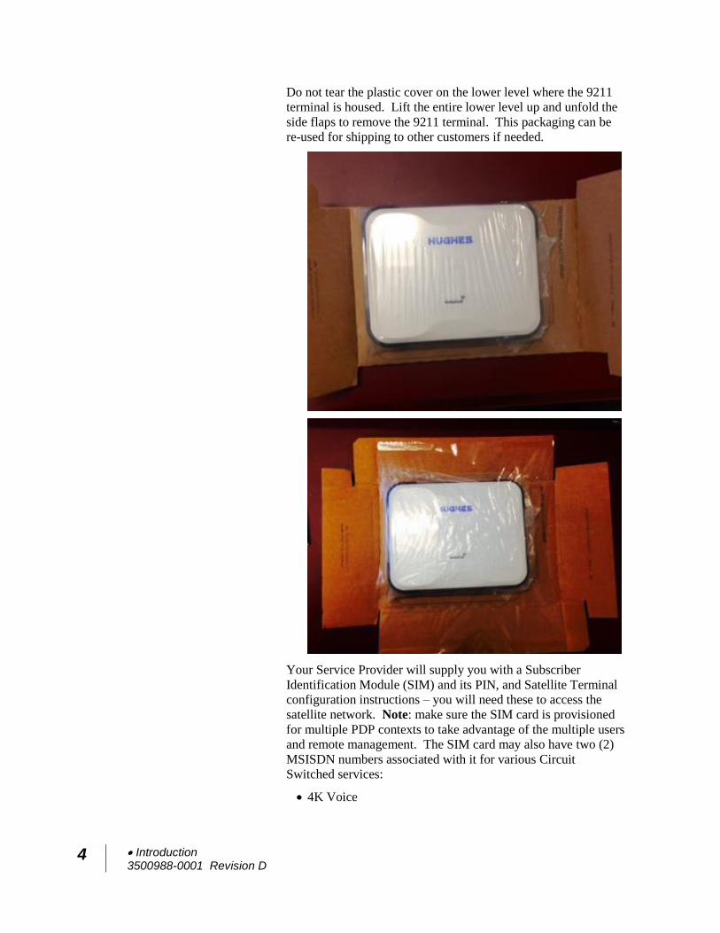
Do not tear the plastic cover on the lower level where the 9211
terminal is housed. Lift the entire lower level up and unfold the
side flaps to remove the 9211 terminal. This packaging can be
re-used for shipping to other customers if needed.
Your Service Provider will supply you with a Subscriber
Identification Module (SIM) and its PIN, and Satellite Terminal
configuration instructions – you will need these to access the
satellite network. Note: make sure the SIM card is provisioned
for multiple PDP contexts to take advantage of the multiple users
and remote management. The SIM card may also have two (2)
MSISDN numbers associated with it for various Circuit
Switched services:
4K Voice
Introduction 3500988-0001 Revision D
5
3.1KHz Audio/Fax
9202M Package Contents
When you unpack the Hughes 9202M Land Portable Terminal
Kit package, you will find the following:
Hughes 9202M terminal
AC/DC power adapter
US, EU and UK power cords
Ethernet cable
Lithium Ion battery
Your Service Provider will supply you with a Subscriber
Identification Module (SIM) and its PIN, and Satellite Terminal
configuration instructions – you will need these to access the
satellite network. Note: The SIM card may also have two (2)
MSISDN numbers associated with it for various Circuit
Switched services:
4K Voice
3.1KHz Audio/Fax
Minimum System Requirements for Laptop/PC
These are the minimum computer system requirements for
successful interface with the Satellite Terminal:
Internet Browser: Microsoft Internet Explorer (IE8 or
above), Edge, Firefox or Safari. Chrome can be used but
does not support downloading files from the Support page.
PC Support for Ethernet or WLAN (802.11b or b/g/n).
100 MB of free hard disk space if using LaunchPad. Only
LaunchPad version 5.0.7 or newer supports the 9211. The
9202M is currently not supported by LaunchPad.
Getting Started
This guide is the simplest and quickest way to connect to the
BGAN network. If you are a first time user, you will be
guided through the procedure for powering up your terminal,
obtaining a GPS fix, connecting your computer to the terminal
and registering with the BGAN network. You are then ready
to start using voice and broadband services.
6 Introduction 3500988-0001 Revision D
Information for Maintenance
In the event that a Hughes terminal develops a problem, please
follow the instructions below.
For Users:
Please contact the company that you purchased the terminal from
so that they can request an RMA from Hughes for your terminal.
For Distribution Providers:
Should a Hughes terminal need to be returned for repair, an
RMA will be required.
To request an RMA access the Customer Care Portal at
https://customergateway.hns.com
Alternatively, an RMA may be requested via Email to
Ship the unit to the Hughes repair center at the
following address; be sure to include the RMA number
on the address label.
Hughes Network Systems
Attn: RMA # XXXXXXXXX
Material Return Center
16060 Industrial Drive
Gaithersburg, MD 20877
USA
Date of Manufacture
If it is necessary to determine the date of manufacture of a unit,
e-mail Hughes at [email protected] and
provide the IMEI from the unit label.
Manufacturer Contact
For other general queries, contact Hughes at:
11717 Exploration Lane, Germantown, MD 20876, USA
+1 (301) 428-5500
www.hughes.com
Using the Terminal 3500988-0001 Revision D
7
Using the Terminal
Setup
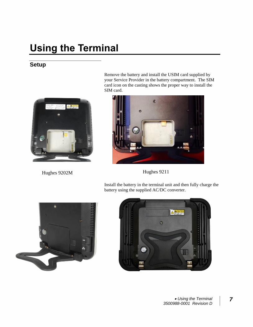
Remove the battery and install the USIM card supplied by
your Service Provider in the battery compartment. The SIM
card icon on the casting shows the proper way to install the
SIM card.
Install the battery in the terminal unit and then fully charge the
battery using the supplied AC/DC converter.
Hughes 9202M Hughes 9211
8 Using the Terminal 3500988-0001 Revision D
LCD Quick Start
Press the power button for at least two (2) seconds in order to
Power On the terminal. The LCD will display “Hughes 9211”
or “Hughes 9202” for about 30 seconds while the terminal is
booting up.
Since the terminal is a portable device, you must first obtain a
GPS fix and then point the terminal to the Inmarsat satellite
before setting up a data connection with the network.
You can use the LCD display to aid in pointing as described in
Using the LCD and Keypad on Page 18.
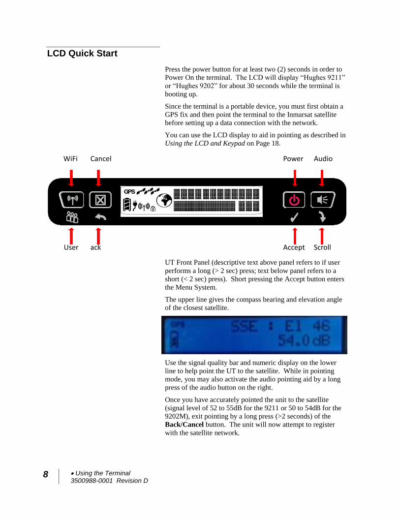
UT Front Panel (descriptive text above panel refers to if user
performs a long (> 2 sec) press; text below panel refers to a
short (< 2 sec) press). Short pressing the Accept button enters
the Menu System.
The upper line gives the compass bearing and elevation angle
of the closest satellite.
Use the signal quality bar and numeric display on the lower
line to help point the UT to the satellite. While in pointing
mode, you may also activate the audio pointing aid by a long
press of the audio button on the right.
Once you have accurately pointed the unit to the satellite
(signal level of 52 to 55dB for the 9211 or 50 to 54dB for the
9202M), exit pointing by a long press (>2 seconds) of the
Back/Cancel button. The unit will now attempt to register
with the satellite network.
Scroll ack
croll
Accept User
Audio Cancel Power WiFi
Using the Terminal 3500988-0001 Revision D
9
Once the unit has registered and is Circuit Switched (CS) and
Packet Switched (PS) attached (“Ready” on the LCD), you can
create a data connection from the menu by first pressing the
Accept button to enter the menu system, then by scrolling
through the various selections and by pressing the Accept
button when the LCD says Connection. Scroll through the
various QoS’s and select the appropriate one for your
application by again pressing the Accept button.
Web UI Quick Start
Alternatively, you can connect a computer and use the
terminal’s internal web server. From your terminal equipment
(e.g. PC), enter 192.168.128.100 as the URL to access the
Home page (see Using the Web UI for more details). Note:
the product number in the top left will be 9202 for the 9202M.
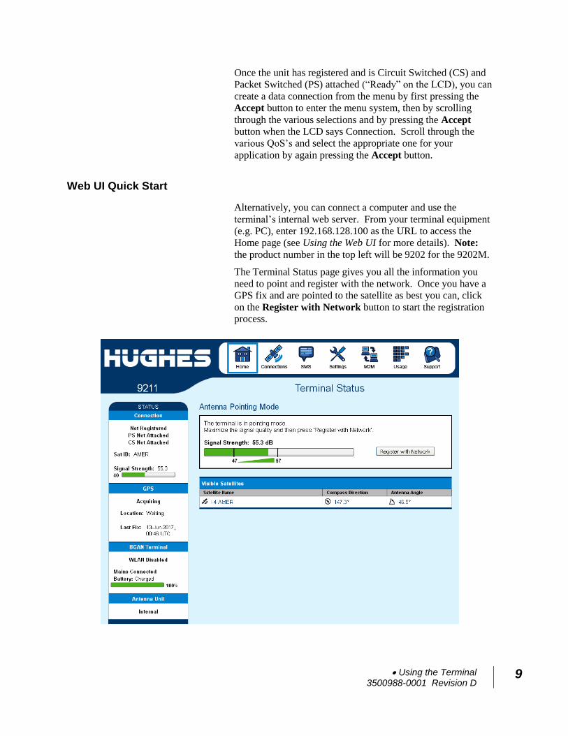
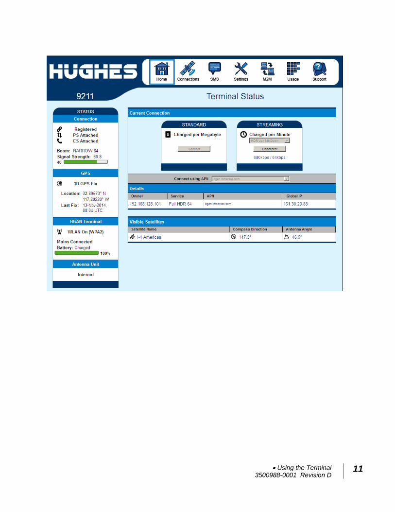
The Terminal Status page gives you all the information you
need to point and register with the network. Once you have a
GPS fix and are pointed to the satellite as best you can, click
on the Register with Network button to start the registration process.
10 Using the Terminal 3500988-0001 Revision D
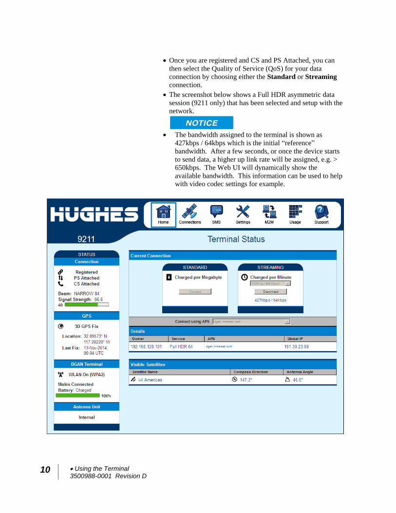
Once you are registered and CS and PS Attached, you can
then select the Quality of Service (QoS) for your data
connection by choosing either the Standard or Streaming
connection.
The screenshot below shows a Full HDR asymmetric data
session (9211 only) that has been selected and setup with the network.
The bandwidth assigned to the terminal is shown as
427kbps / 64kbps which is the initial “reference”
bandwidth. After a few seconds, or once the device starts
to send data, a higher up link rate will be assigned, e.g. >
650kbps. The Web UI will dynamically show the
available bandwidth. This information can be used to help with video codec settings for example.
Using the Terminal 3500988-0001 Revision D
11
12 Using the Terminal 3500988-0001 Revision D
Connecting the terminal to the computer
You can connect your computer to the UT with one or more of
the following interfaces
Ethernet
WLAN
Your computer must be configured to support your chosen
connection method. Refer to the documentation supplied
with your computer for details.
Connecting by Ethernet
To connect the Hughes UT terminal to a device using Ethernet:
Connect an Ethernet cable to your device’s Ethernet port,
and insert the other end of the connector into the Ethernet
port on the UT.
Connecting by WLAN
If you have not previously used the UT’s WLAN interface, it
has to be enabled from the UT’s front-panel keypad, or you
can connect via Ethernet and use the internal Web UI.
During initial setup, you can turn on Wi-Fi by long pressing (>
2 seconds) the button. Once the icon shows
solid on the LCD, you can continue to configure the terminal
or setup a data session using your wirelessly connected device.
WLAN Power: The default is off, which disables the
WLAN feature.
SSID (network name): The default is “Hughes 9211” or
“Hughes 9202”, but you can change it to whatever you want.
Channel Number: This controls the radio channel number (1
through 11) used by the access point. To meet FCC
regulations, channels 12 to 14 are not supported.
As you are configuring the WLAN, you can enable the
Wireless LAN Encryption (WEP (older releases only), WPA
and WPA2), MAC address filtering, and no SSID broadcast
features for added security.
Using the Terminal 3500988-0001 Revision D
13
Once the WLAN is “Enabled” and configured, any device with
a WLAN interface can detect the UT’s WLAN SSID, and
connect to it automatically.
In PPPoE mode, you can connect to the Web UI via WLAN,
but you can’t activate PDP contexts or send data over the
spacelink via WLAN – you have to use the Ethernet interface.
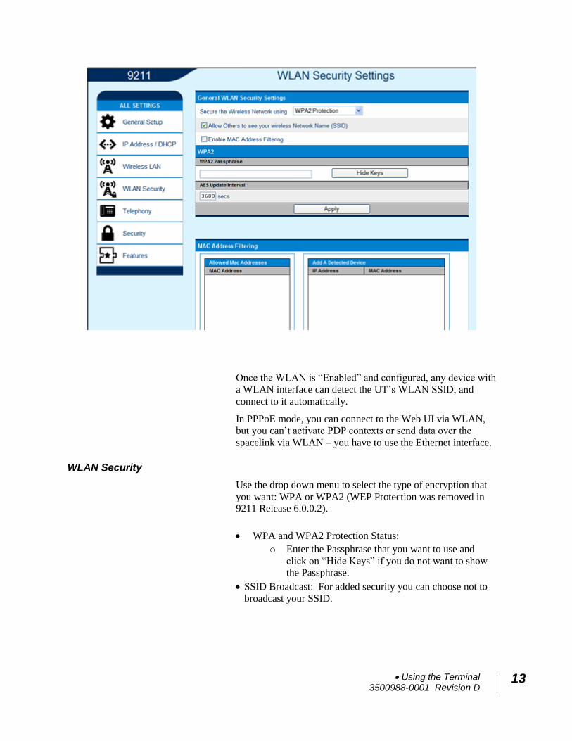
WLAN Security
Use the drop down menu to select the type of encryption that
you want: WPA or WPA2 (WEP Protection was removed in 9211 Release 6.0.0.2).
WPA and WPA2 Protection Status:
o Enter the Passphrase that you want to use and
click on “Hide Keys” if you do not want to show the Passphrase.
SSID Broadcast: For added security you can choose not to
broadcast your SSID.
14 Using the Terminal 3500988-0001 Revision D
MAC Filtering: For added security, check the box to
“Enable” MAC Filtering. You can define up to 10 MAC addresses that are allowed to connect to your WLAN.
To determine the MAC address of a PC, go to a DOS prompt
and type ipconfig/all.
For Mac OS X, under the Apple Menu go to System
Preferences -> Network and Show Airport. The Airport Id
is the MAC address. Alternatively, go to About this Mac -
> More Info -> Network, and select Airport.
When WLAN is enabled, unauthorized users may be able to
access your BGAN service. If encryption is enabled, you must
provide other WLAN users with the proper encryption key or
passphrase in order for them to connect to the terminal. You
can go to the Manage Connections page on the Web UI to see
what computers are actually using the BGAN service.
Connecting by RJ11
You can connect an analog phone directly to the RJ14 port
with an RJ11 cable to make voice calls.
If you wish to use the fax port you can connect an RJ14
connector that breaks out the two RJ11 ports into Line 1 and
Line 2. You can then connect to port 2 to access the 3.1k
service for fax (see the Application Note at the end of this User
Manual).
If you have a device that supports voice and 3.1 KHz/fax on a
single line, you can configure the RJ14 port to support both
services on line 1. On the Telephony Settings page, set the
field “Route incoming 3.1kHz/fax calls to” “RJ14 port 1”
and simply connect the device directly to the RJ14 port with an
RJ11 cable. With this setting, all incoming calls are then
routed to RJ14 line 1.
To initiate an outgoing 3.1kHz/fax call when connected to line
1, add a 2* prefix in front of the dialed number. For voice
calls, no prefix is required, but the UT will accept a 1* prefix
to indicate a voice call.
To receive incoming calls on line 1, change the Route
incoming 3.1KHz/fax calls parameter on the Telephony
Settings page to “RJ14 Line 1” using the drop down menu.
Using the Terminal 3500988-0001 Revision D
15
Dialing and Numbering
Dialing - As the BGAN numbering system follows the same
pattern as the normal telephone system, dialing is carried out
in exactly the same manner as making a normal telephone call.
The subscriber number is used with the same international and
area codes as any other telephone network. Start the dialed
number with 00 and terminate it with #. If you are calling
another BGAN unit, you need to dial 00 then the 870 number
and then # to initiate the call.
To dial, prefix the international number with 00 and terminate
with #. For example, to dial a number in the USA, enter:
0018005551234# (00 + Country code + phone number+ #)
External Antenna The UT terminal has an external antenna port that can be used
to connect the existing mobile antennas for Class 10 and Class
11 so that they can be used with the terminal to get comms-on-
the-move. (Note that HDR streaming QoS is not supported
with the class 10 and 11 antennas.)
16 Using the Terminal 3500988-0001 Revision D
Coverage Map
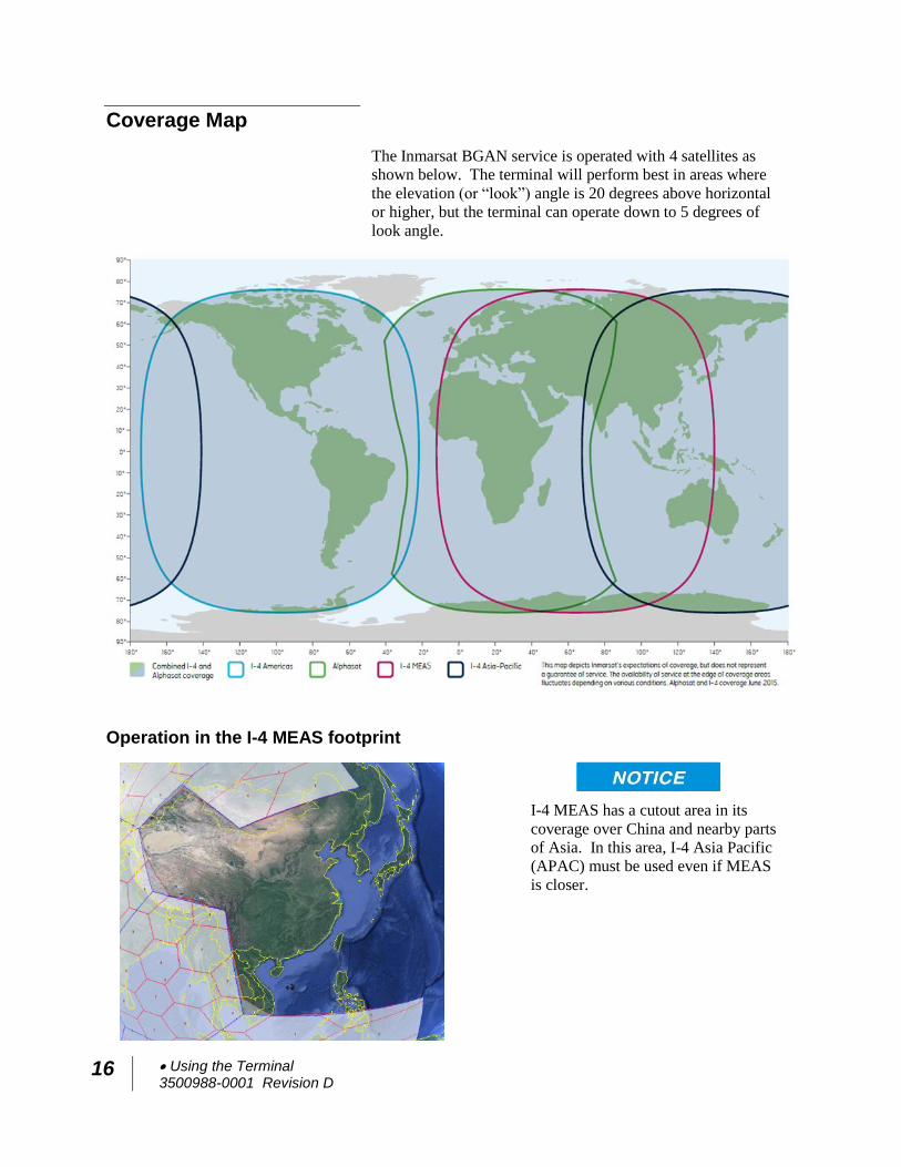
The Inmarsat BGAN service is operated with 4 satellites as
shown below. The terminal will perform best in areas where
the elevation (or “look”) angle is 20 degrees above horizontal
or higher, but the terminal can operate down to 5 degrees of
look angle.
Operation in the I-4 MEAS footprint
I-4 MEAS has a cutout area in its
coverage over China and nearby parts
of Asia. In this area, I-4 Asia Pacific
(APAC) must be used even if MEAS
is closer.
Using the Terminal 3500988-0001 Revision D
17
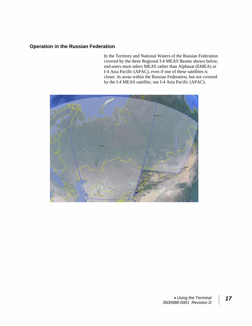
Operation in the Russian Federation
In the Territory and National Waters of the Russian Federation
covered by the three Regional I-4 MEAS Beams shown below,
end-users must select MEAS rather than Alphasat (EMEA) or
I-4 Asia Pacific (APAC), even if one of these satellites is
closer. In areas within the Russian Federation, but not covered
by the I-4 MEAS satellite, use I-4 Asia Pacific (APAC).
18 Using the LCD and Keypad 3500988-0001 Revision D
Using the LCD and Keypad
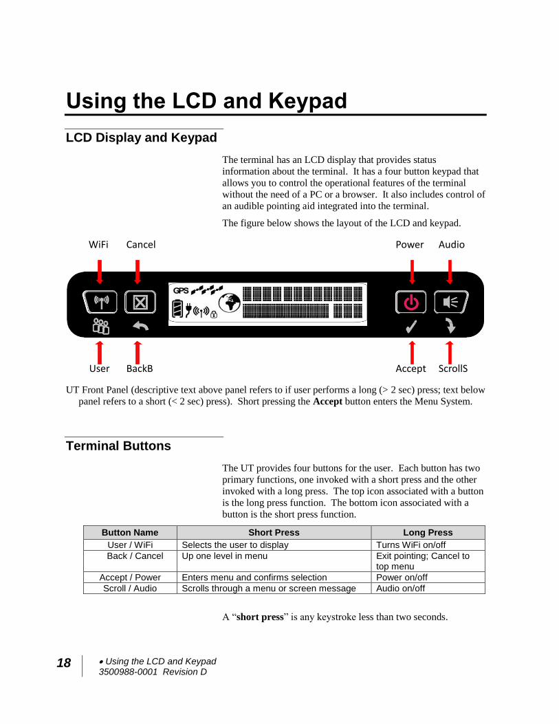
LCD Display and Keypad
The terminal has an LCD display that provides status
information about the terminal. It has a four button keypad that
allows you to control the operational features of the terminal
without the need of a PC or a browser. It also includes control of
an audible pointing aid integrated into the terminal.
The figure below shows the layout of the LCD and keypad.
UT Front Panel (descriptive text above panel refers to if user performs a long (> 2 sec) press; text below
panel refers to a short (< 2 sec) press). Short pressing the Accept button enters the Menu System.
Terminal Buttons
The UT provides four buttons for the user. Each button has two
primary functions, one invoked with a short press and the other
invoked with a long press. The top icon associated with a button
is the long press function. The bottom icon associated with a
button is the short press function.
Button Name Short Press Long Press
User / WiFi Selects the user to display Turns WiFi on/off
Back / Cancel Up one level in menu Exit pointing; Cancel to top menu
Accept / Power Enters menu and confirms selection Power on/off
Scroll / Audio Scrolls through a menu or screen message Audio on/off
A “short press” is any keystroke less than two seconds.
ScrollSBackB
ScrollS
AcceptUser
AudioCancel PowerWiFi
Using the LCD and Keypad 3500988-0001 Revision D
19
A “long press” is any keystroke that is two seconds or greater.
An “extra long press” of more than five seconds of the power
button will cause a hardware enforced power down.
Any button press starts or restarts the (configurable) backlight
time period, even if it has no function in the current context.
LCD Status Display
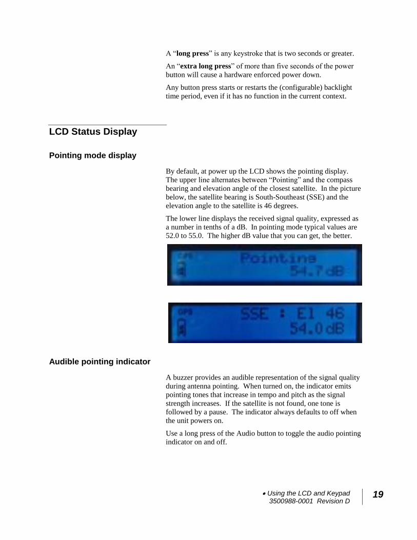
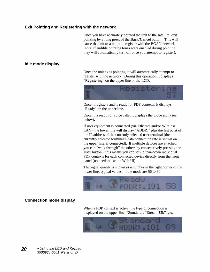
Pointing mode display
By default, at power up the LCD shows the pointing display.
The upper line alternates between “Pointing” and the compass
bearing and elevation angle of the closest satellite. In the picture
below, the satellite bearing is South-Southeast (SSE) and the
elevation angle to the satellite is 46 degrees.
The lower line displays the received signal quality, expressed as
a number in tenths of a dB. In pointing mode typical values are
52.0 to 55.0. The higher dB value that you can get, the better.
Audible pointing indicator
A buzzer provides an audible representation of the signal quality
during antenna pointing. When turned on, the indicator emits
pointing tones that increase in tempo and pitch as the signal
strength increases. If the satellite is not found, one tone is
followed by a pause. The indicator always defaults to off when
the unit powers on.
Use a long press of the Audio button to toggle the audio pointing
indicator on and off.
20 Using the LCD and Keypad 3500988-0001 Revision D
Exit Pointing and Registering with the network
Once you have accurately pointed the unit to the satellite, exit
pointing by a long press of the Back/Cancel button. This will
cause the unit to attempt to register with the BGAN network
(note: if audible pointing tones were enabled during pointing,
they will automatically turn off once you attempt to register).
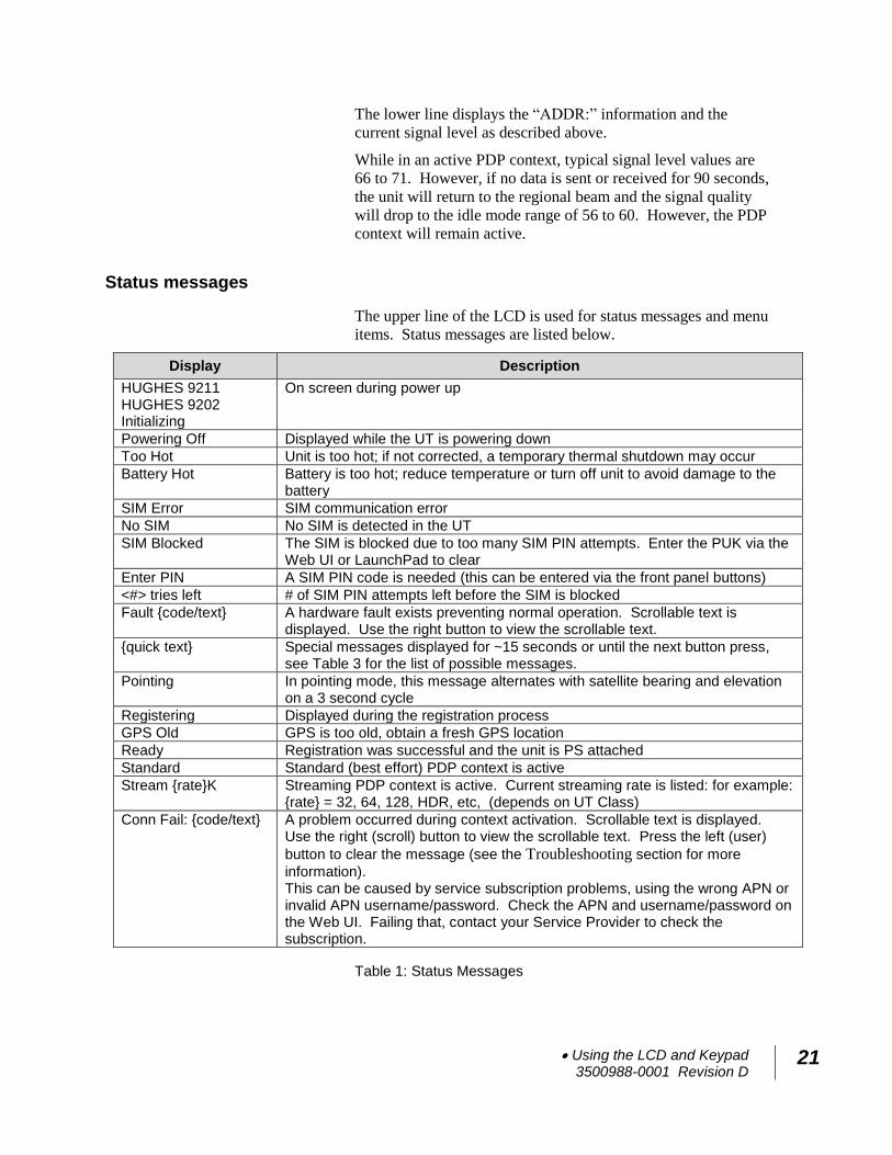
Idle mode display
Once the unit exits pointing, it will automatically attempt to
register with the network. During this operation it displays
“Registering” on the upper line of the LCD.
Once it registers and is ready for PDP contexts, it displays
“Ready” on the upper line.
Once it is ready for voice calls, it displays the globe icon (see
below).
If user equipment is connected (via Ethernet and/or Wireless
LAN), the lower line will display “ADDR:” plus the last octet of
the IP address of the currently selected user terminal (the
currently selected terminal’s data connection rate is shown on
the upper line, if connected). If multiple devices are attached,
you can “walk through” the others by consecutively pressing the
User button – this means you can set-up/tear-down individual
PDP contexts for each connected device directly from the front
panel (no need to use the Web UI).
The signal quality is shown as a number in the right corner of the
lower line; typical values in idle mode are 56 to 60.
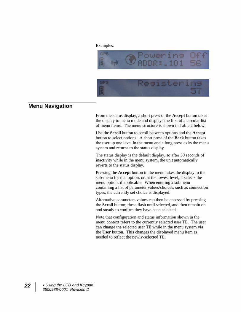
Connection mode display
When a PDP context is active, the type of connection is
displayed on the upper line: “Standard”, “Stream 32k”, etc.
Using the LCD and Keypad 3500988-0001 Revision D
21
The lower line displays the “ADDR:” information and the
current signal level as described above.
While in an active PDP context, typical signal level values are
66 to 71. However, if no data is sent or received for 90 seconds,
the unit will return to the regional beam and the signal quality
will drop to the idle mode range of 56 to 60. However, the PDP
context will remain active.
Status messages
The upper line of the LCD is used for status messages and menu
items. Status messages are listed below.
Display Description
HUGHES 9211 HUGHES 9202 Initializing
On screen during power up
Powering Off Displayed while the UT is powering down
Too Hot Unit is too hot; if not corrected, a temporary thermal shutdown may occur
Battery Hot Battery is too hot; reduce temperature or turn off unit to avoid damage to the battery
SIM Error SIM communication error
No SIM No SIM is detected in the UT
SIM Blocked The SIM is blocked due to too many SIM PIN attempts. Enter the PUK via the Web UI or LaunchPad to clear
Enter PIN A SIM PIN code is needed (this can be entered via the front panel buttons)
<#> tries left # of SIM PIN attempts left before the SIM is blocked
Fault {code/text} A hardware fault exists preventing normal operation. Scrollable text is displayed. Use the right button to view the scrollable text.
{quick text} Special messages displayed for ~15 seconds or until the next button press, see Table 3 for the list of possible messages.
Pointing In pointing mode, this message alternates with satellite bearing and elevation on a 3 second cycle
Registering Displayed during the registration process
GPS Old GPS is too old, obtain a fresh GPS location
Ready Registration was successful and the unit is PS attached
Standard Standard (best effort) PDP context is active
Stream {rate}K Streaming PDP context is active. Current streaming rate is listed: for example: {rate} = 32, 64, 128, HDR, etc, (depends on UT Class)
Conn Fail: {code/text} A problem occurred during context activation. Scrollable text is displayed. Use the right (scroll) button to view the scrollable text. Press the left (user)
button to clear the message (see the Troubleshooting section for more
information). This can be caused by service subscription problems, using the wrong APN or invalid APN username/password. Check the APN and username/password on the Web UI. Failing that, contact your Service Provider to check the subscription.
Table 1: Status Messages
22 Using the LCD and Keypad 3500988-0001 Revision D
Examples:
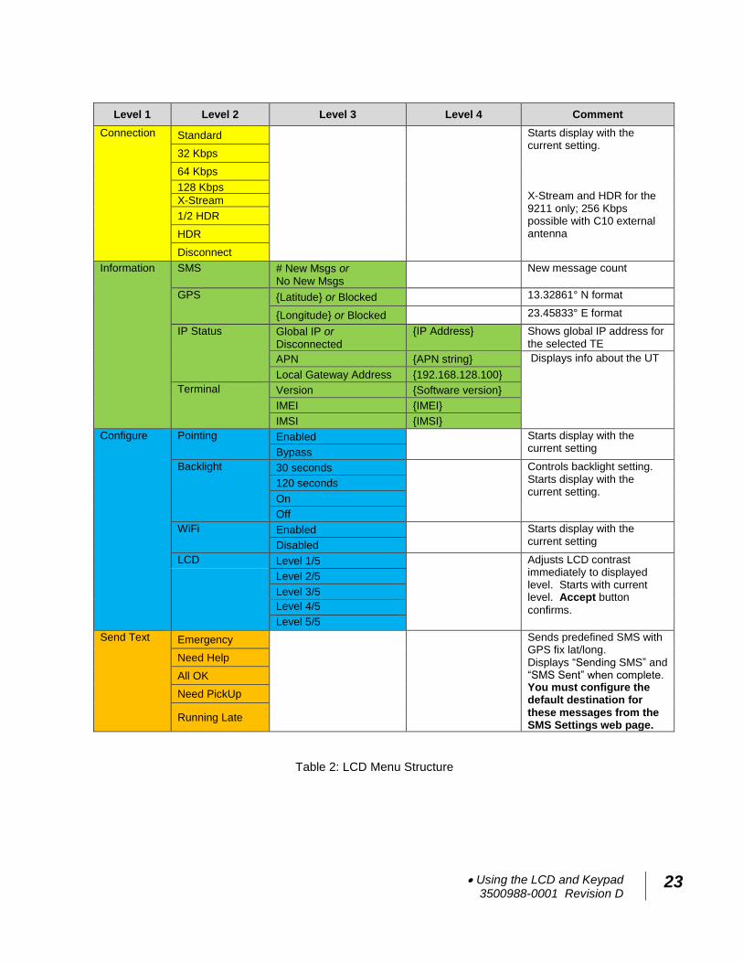
Menu Navigation
From the status display, a short press of the Accept button takes
the display to menu mode and displays the first of a circular list
of menu items. The menu structure is shown in Table 2 below.
Use the Scroll button to scroll between options and the Accept
button to select options. A short press of the Back button takes
the user up one level in the menu and a long press exits the menu
system and returns to the status display.
The status display is the default display, so after 30 seconds of
inactivity while in the menu system, the unit automatically
reverts to the status display.
Pressing the Accept button in the menu takes the display to the
sub-menu for that option, or, at the lowest level, it selects the
menu option, if applicable. When entering a submenu
containing a list of parameter values/choices, such as connection
types, the currently set choice is displayed.
Alternative parameters values can then be accessed by pressing
the Scroll button; these flash until selected, and then remain on
and steady to confirm they have been selected.
Note that configuration and status information shown in the
menu context refers to the currently selected user TE. The user
can change the selected user TE while in the menu system via
the User button. This changes the displayed menu item as
needed to reflect the newly-selected TE.
Using the LCD and Keypad 3500988-0001 Revision D
23
Level 1 Level 2 Level 3 Level 4 Comment
Connection
Standard
Starts display with the current setting. X-Stream and HDR for the 9211 only; 256 Kbps possible with C10 external antenna
32 Kbps
64 Kbps
128 Kbps
X-Stream
1/2 HDR
HDR
Disconnect
Information SMS # New Msgs or No New Msgs
New message count
GPS {Latitude} or Blocked
13.32861° N format
{Longitude} or Blocked
23.45833° E format
IP Status Global IP or Disconnected
{IP Address} Shows global IP address for the selected TE
APN {APN string} Displays info about the UT
Local Gateway Address {192.168.128.100}
Terminal Version {Software version}
IMEI {IMEI}
IMSI {IMSI}
Configure
Pointing Enabled
Starts display with the current setting Bypass
Backlight 30 seconds
Controls backlight setting. Starts display with the current setting.
120 seconds
On
Off
WiFi Enabled
Starts display with the current setting Disabled
LCD Level 1/5 Adjusts LCD contrast immediately to displayed level. Starts with current level. Accept button
confirms.
Level 2/5
Level 3/5
Level 4/5
Level 5/5
Send Text Emergency
Sends predefined SMS with GPS fix lat/long. Displays “Sending SMS” and “SMS Sent” when complete. You must configure the default destination for these messages from the SMS Settings web page.
Need Help
All OK
Need PickUp
Running Late
Table 2: LCD Menu Structure
24 Using the LCD and Keypad 3500988-0001 Revision D
Display Icons
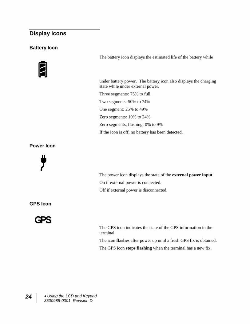
Battery Icon
The battery icon displays the estimated life of the battery while
under battery power. The battery icon also displays the charging
state while under external power.
Three segments: 75% to full
Two segments: 50% to 74%
One segment: 25% to 49%
Zero segments: 10% to 24%
Zero segments, flashing: 0% to 9%
If the icon is off, no battery has been detected.
Power Icon
The power icon displays the state of the external power input.
On if external power is connected.
Off if external power is disconnected.
GPS Icon
The GPS icon indicates the state of the GPS information in the
terminal.
The icon flashes after power up until a fresh GPS fix is obtained.
The GPS icon stops flashing when the terminal has a new fix.
Using the LCD and Keypad 3500988-0001 Revision D
25
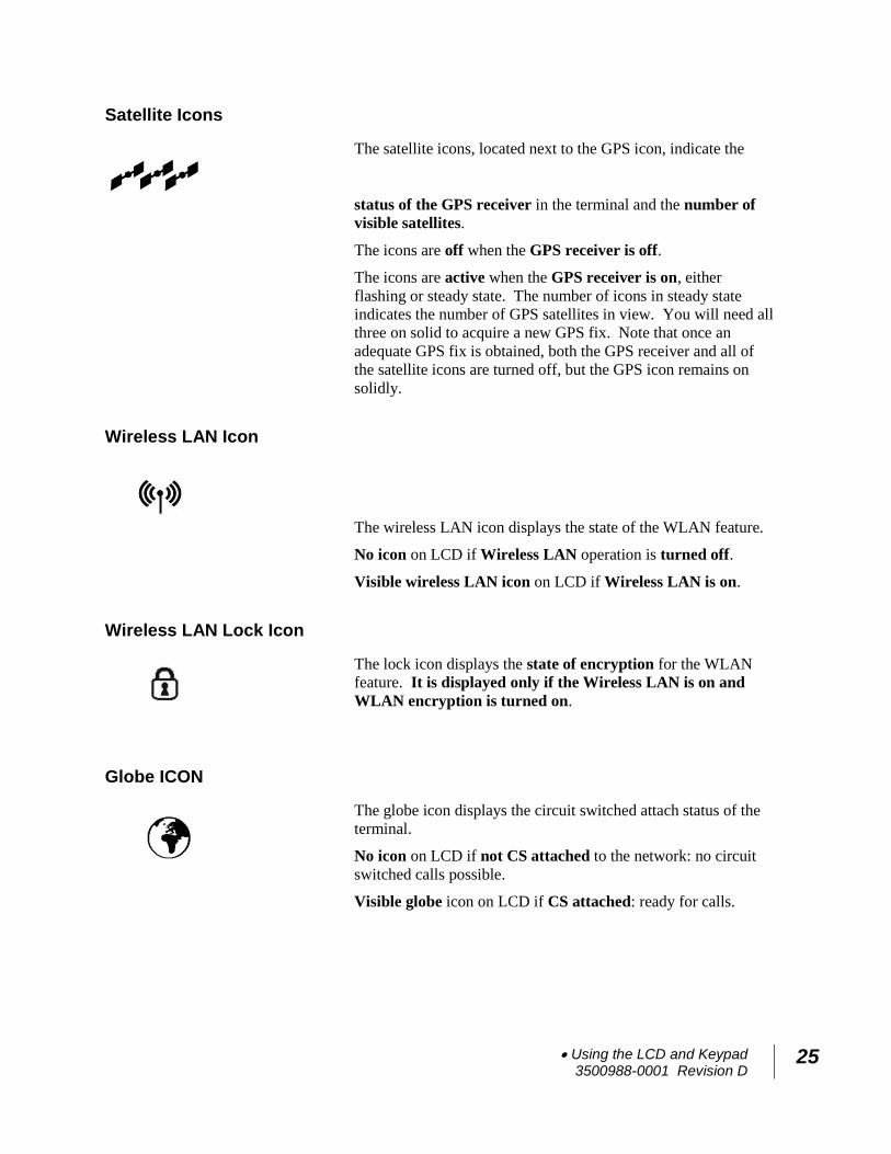
Satellite Icons
The satellite icons, located next to the GPS icon, indicate the
status of the GPS receiver in the terminal and the number of
visible satellites.
The icons are off when the GPS receiver is off.
The icons are active when the GPS receiver is on, either
flashing or steady state. The number of icons in steady state
indicates the number of GPS satellites in view. You will need all
three on solid to acquire a new GPS fix. Note that once an
adequate GPS fix is obtained, both the GPS receiver and all of
the satellite icons are turned off, but the GPS icon remains on
solidly.
Wireless LAN Icon
The wireless LAN icon displays the state of the WLAN feature.
No icon on LCD if Wireless LAN operation is turned off.
Visible wireless LAN icon on LCD if Wireless LAN is on.
Wireless LAN Lock Icon
The lock icon displays the state of encryption for the WLAN
feature. It is displayed only if the Wireless LAN is on and
WLAN encryption is turned on.
Globe ICON
The globe icon displays the circuit switched attach status of the
terminal.
No icon on LCD if not CS attached to the network: no circuit
switched calls possible.
Visible globe icon on LCD if CS attached: ready for calls.
26 Using the LCD and Keypad 3500988-0001 Revision D
SIM PIN entry
If the SIM PIN is enabled, the PIN must be entered before the
UT can be used. This can be entered via the Web UI,
LaunchPad, or the front-panel keypad.
The upper row of the LCD displays “Enter PIN” while the lower
row is used for PIN entry.
The cursor flashes under the current digit location.
A short press of the Scroll button cycles the current digit 0 – 9.
A short press of the Accept button advances to the next digit.
When the 4th digit is entered, pressing Accept enters the PIN.
A short press of the Back button moves the cursor back to the
previous digit.
When PIN entry is complete, the UT confirms the correct PIN
has been entered. If it is correct, it proceeds with the normal
display. If it is incorrect, it displays “<#> tries left” on the
display, where “#” is the number of attempts remaining prior to
the SIM being blocked.
Multiple Users
Multiple TEs can be connected to the UT, e.g. via the wireless
LAN interface or if an external hub or switch is used. To use the
menu and keypad to control connections for all the TEs, short
press (< 2 seconds) the User button and the display will cycle
through the IP addresses of the connected TEs.
To activate a context for a particular TE, press the User button
until the correct IP address is displayed, and then press the
Accept button to enter the menu and control the PDP context.
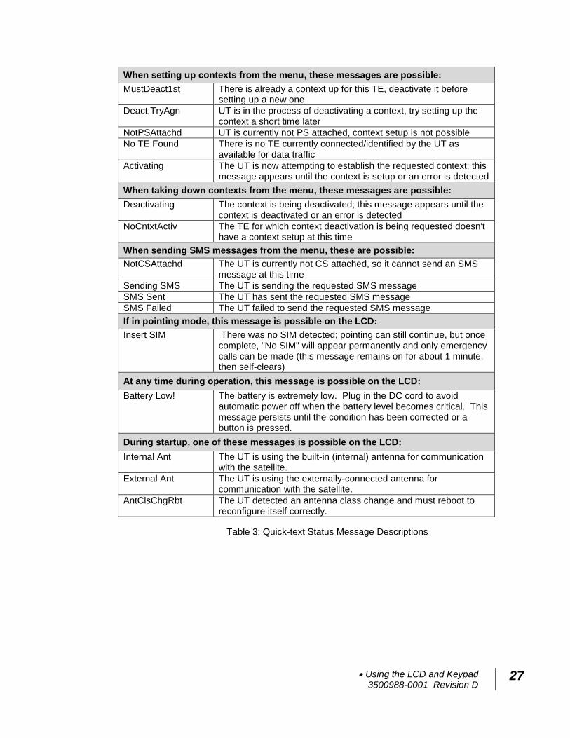
Information Messages
The following table shows possible error and status messages
with explanations and suggested actions. Most of these
messages will self-clear after 15 seconds, or can be cleared
immediately by pressing any button on the front panel.
Using the LCD and Keypad 3500988-0001 Revision D
27
When setting up contexts from the menu, these messages are possible:
MustDeact1st There is already a context up for this TE, deactivate it before setting up a new one
Deact;TryAgn UT is in the process of deactivating a context, try setting up the context a short time later
NotPSAttachd UT is currently not PS attached, context setup is not possible
No TE Found There is no TE currently connected/identified by the UT as available for data traffic
Activating The UT is now attempting to establish the requested context; this message appears until the context is setup or an error is detected
When taking down contexts from the menu, these messages are possible:
Deactivating The context is being deactivated; this message appears until the context is deactivated or an error is detected
NoCntxtActiv The TE for which context deactivation is being requested doesn't have a context setup at this time
When sending SMS messages from the menu, these are possible:
NotCSAttachd The UT is currently not CS attached, so it cannot send an SMS message at this time
Sending SMS The UT is sending the requested SMS message
SMS Sent The UT has sent the requested SMS message
SMS Failed The UT failed to send the requested SMS message
If in pointing mode, this message is possible on the LCD:
Insert SIM There was no SIM detected; pointing can still continue, but once complete, "No SIM" will appear permanently and only emergency calls can be made (this message remains on for about 1 minute, then self-clears)
At any time during operation, this message is possible on the LCD:
Battery Low! The battery is extremely low. Plug in the DC cord to avoid automatic power off when the battery level becomes critical. This message persists until the condition has been corrected or a button is pressed.
During startup, one of these messages is possible on the LCD:
Internal Ant The UT is using the built-in (internal) antenna for communication with the satellite.
External Ant The UT is using the externally-connected antenna for communication with the satellite.
AntClsChgRbt The UT detected an antenna class change and must reboot to reconfigure itself correctly.
Table 3: Quick-text Status Message Descriptions
28 Using the Web UI 3500988-0001 Revision D
Using the Web UI
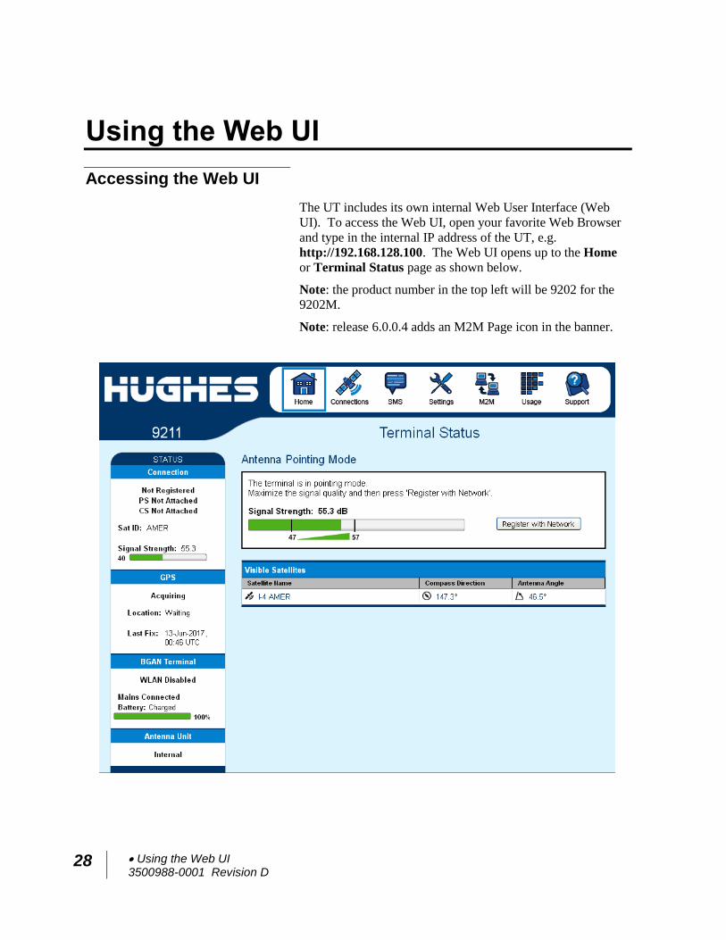
Accessing the Web UI
The UT includes its own internal Web User Interface (Web
UI). To access the Web UI, open your favorite Web Browser
and type in the internal IP address of the UT, e.g.
http://192.168.128.100. The Web UI opens up to the Home
or Terminal Status page as shown below.
Note: the product number in the top left will be 9202 for the
9202M.
Note: release 6.0.0.4 adds an M2M Page icon in the banner.
Using the Web UI 3500988-0001 Revision D
29
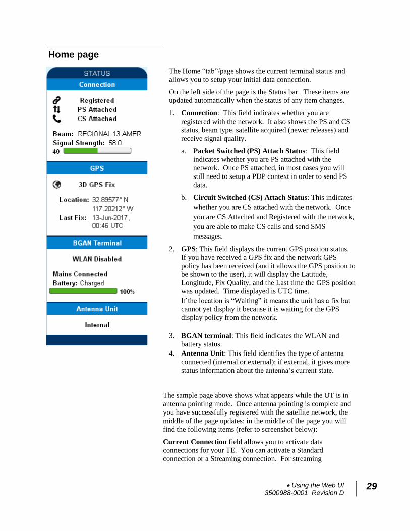
Home page
The Home “tab”/page shows the current terminal status and
allows you to setup your initial data connection.
On the left side of the page is the Status bar. These items are
updated automatically when the status of any item changes.
1. Connection: This field indicates whether you are
registered with the network. It also shows the PS and CS
status, beam type, satellite acquired (newer releases) and
receive signal quality.
a. Packet Switched (PS) Attach Status: This field
indicates whether you are PS attached with the
network. Once PS attached, in most cases you will
still need to setup a PDP context in order to send PS
data.
b. Circuit Switched (CS) Attach Status: This indicates
whether you are CS attached with the network. Once
you are CS Attached and Registered with the network,
you are able to make CS calls and send SMS
messages.
2. GPS: This field displays the current GPS position status.
If you have received a GPS fix and the network GPS
policy has been received (and it allows the GPS position to
be shown to the user), it will display the Latitude,
Longitude, Fix Quality, and the Last time the GPS position
was updated. Time displayed is UTC time.
If the location is “Waiting” it means the unit has a fix but
cannot yet display it because it is waiting for the GPS
display policy from the network.
3. BGAN terminal: This field indicates the WLAN and
battery status.
4. Antenna Unit: This field identifies the type of antenna
connected (internal or external); if external, it gives more
status information about the antenna’s current state.
The sample page above shows what appears while the UT is in
antenna pointing mode. Once antenna pointing is complete and
you have successfully registered with the satellite network, the
middle of the page updates: in the middle of the page you will
find the following items (refer to screenshot below):
Current Connection field allows you to activate data
connections for your TE. You can activate a Standard
connection or a Streaming connection. For streaming
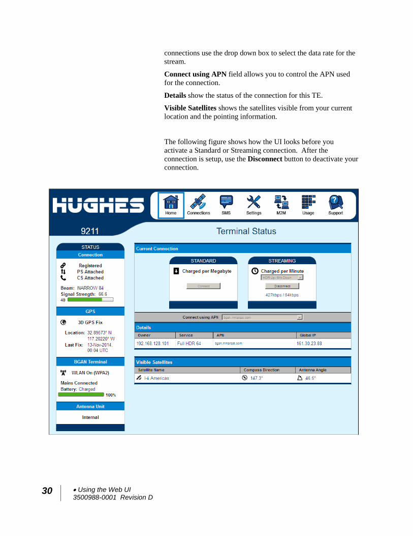
30 Using the Web UI 3500988-0001 Revision D
connections use the drop down box to select the data rate for the
stream.
Connect using APN field allows you to control the APN used
for the connection.
Details show the status of the connection for this TE.
Visible Satellites shows the satellites visible from your current
location and the pointing information.
The following figure shows how the UI looks before you
activate a Standard or Streaming connection. After the
connection is setup, use the Disconnect button to deactivate your
connection.
Using the Web UI 3500988-0001 Revision D
31
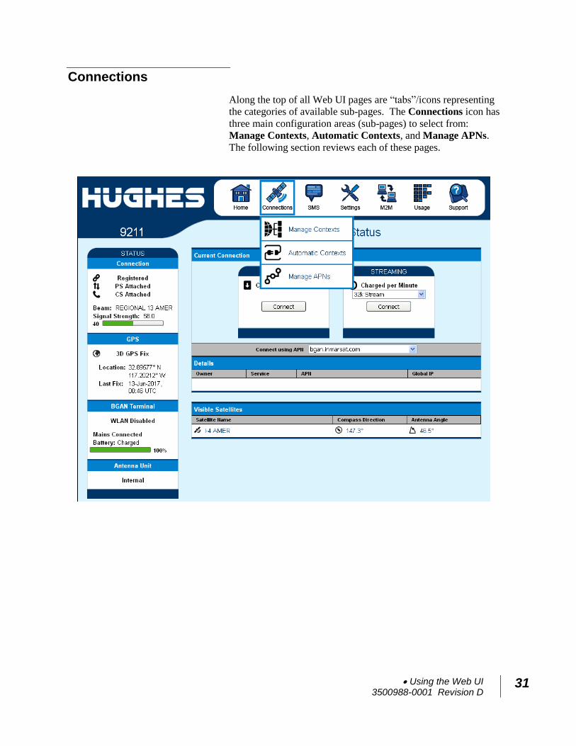
Connections
Along the top of all Web UI pages are “tabs”/icons representing
the categories of available sub-pages. The Connections icon has
three main configuration areas (sub-pages) to select from:
Manage Contexts, Automatic Contexts, and Manage APNs.
The following section reviews each of these pages.
32 Using the Web UI 3500988-0001 Revision D
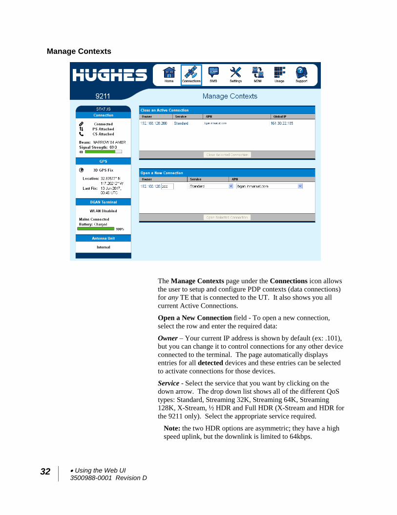
Manage Contexts
The Manage Contexts page under the Connections icon allows
the user to setup and configure PDP contexts (data connections)
for any TE that is connected to the UT. It also shows you all
current Active Connections.
Open a New Connection field - To open a new connection,
select the row and enter the required data:
Owner – Your current IP address is shown by default (ex: .101),
but you can change it to control connections for any other device
connected to the terminal. The page automatically displays
entries for all detected devices and these entries can be selected
to activate connections for those devices.
Service - Select the service that you want by clicking on the
down arrow. The drop down list shows all of the different QoS
types: Standard, Streaming 32K, Streaming 64K, Streaming
128K, X-Stream, ½ HDR and Full HDR (X-Stream and HDR for
the 9211 only). Select the appropriate service required.
Note: the two HDR options are asymmetric; they have a high
speed uplink, but the downlink is limited to 64kbps.
Using the Web UI 3500988-0001 Revision D
33
APN - The APN is read from the SIM card, but if you have other
APNs defined (refer to the Manage APNs page), you can use
the down arrow to select a different APN.
Username/Password: Some Service Providers require a
username and password to be used when setting up a connection.
This is often required when using Static Global IP addresses
assigned by the Service Provider. If this information is required,
a “pop-up” dialog will appear once you select the APN. These
fields may also be entered when defining a new APN or when
you select a different APN.
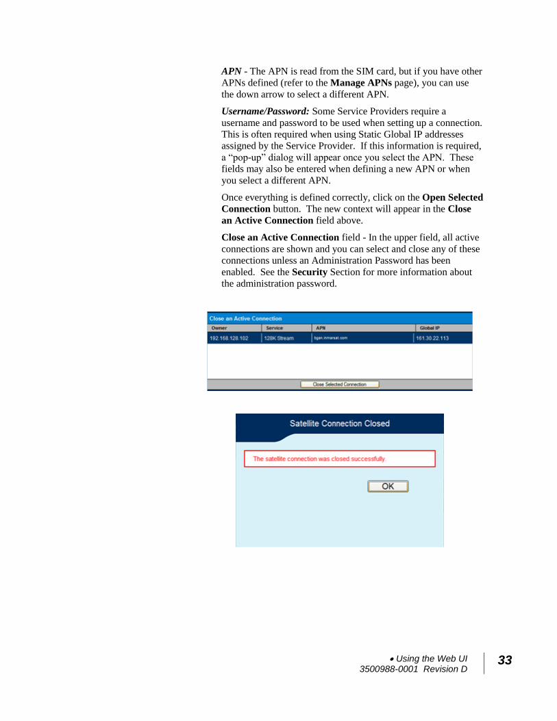
Once everything is defined correctly, click on the Open Selected
Connection button. The new context will appear in the Close
an Active Connection field above.
Close an Active Connection field - In the upper field, all active
connections are shown and you can select and close any of these
connections unless an Administration Password has been
enabled. See the Security Section for more information about
the administration password.
34 Using the Web UI 3500988-0001 Revision D
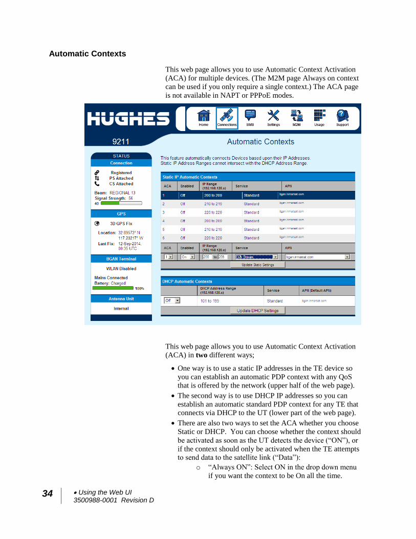
Automatic Contexts
This web page allows you to use Automatic Context Activation
(ACA) for multiple devices. (The M2M page Always on context
can be used if you only require a single context.) The ACA page
is not available in NAPT or PPPoE modes.
This web page allows you to use Automatic Context Activation
(ACA) in two different ways;
One way is to use a static IP addresses in the TE device so
you can establish an automatic PDP context with any QoS that is offered by the network (upper half of the web page).
The second way is to use DHCP IP addresses so you can
establish an automatic standard PDP context for any TE that connects via DHCP to the UT (lower part of the web page).
There are also two ways to set the ACA whether you choose
Static or DHCP. You can choose whether the context should
be activated as soon as the UT detects the device (“ON”), or
if the context should only be activated when the TE attempts to send data to the satellite link (“Data”):
o “Always ON”: Select ON in the drop down menu
if you want the context to be On all the time.
Using the Web UI 3500988-0001 Revision D
35
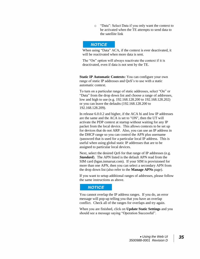
o “Data”: Select Data if you only want the context to
be activated when the TE attempts to send data to
the satellite link
When using “Data” ACA, if the context is ever deactivated, it
will be reactivated when more data is sent.
The “On” option will always reactivate the context if it is
deactivated, even if data is not sent by the TE.
Static IP Automatic Contexts: You can configure your own
range of static IP addresses and QoS’s to use with a static
automatic context.
To turn on a particular range of static addresses, select “On” or
“Data” from the drop down list and choose a range of addresses,
low and high to use (e.g. 192.168.128.200 to 192.168.128.202)
or you can leave the defaults (192.168.128.200 to
192.168.128.209).
In release 6.0.0.2 and higher, if the ACA hi and low IP addresses
are the same and the ACA is set to "ON", then the UT will
activate the PDP context at startup without waiting for any IP
packet from the local device. This allows contexts to be set up
for devices that do not ARP. Also, you can use an IP address in
the DHCP range so you can control the APN plus username
/password that is used for a particular local IP address. This is
useful when using global static IP addresses that are to be
assigned to particular local devices.
Next, select the desired QoS for that range of IP addresses (e.g.
Standard). The APN listed is the default APN read from the
SIM card (bgan.inmarsat.com). If your SIM is provisioned for
more than one APN, then you can select a secondary APN from
the drop down list (also refer to the Manage APNs page).
If you want to setup additional ranges of addresses, please follow
the same instructions as above.
You cannot overlap the IP address ranges. If you do, an error
message will pop-up telling you that you have an overlap
conflict. Check all of the ranges for overlaps and try again.
When you are finished, click on Update Static Settings and you
should see a message saying “Operation Successful”.
36 Using the Web UI 3500988-0001 Revision D
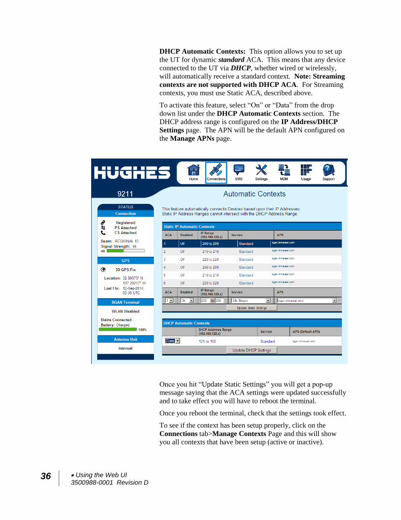
DHCP Automatic Contexts: This option allows you to set up
the UT for dynamic standard ACA. This means that any device
connected to the UT via DHCP, whether wired or wirelessly,
will automatically receive a standard context. Note: Streaming
contexts are not supported with DHCP ACA. For Streaming
contexts, you must use Static ACA, described above.
To activate this feature, select “On” or “Data” from the drop
down list under the DHCP Automatic Contexts section. The
DHCP address range is configured on the IP Address/DHCP
Settings page. The APN will be the default APN configured on
the Manage APNs page.
Once you hit “Update Static Settings” you will get a pop-up
message saying that the ACA settings were updated successfully
and to take effect you will have to reboot the terminal.
Once you reboot the terminal, check that the settings took effect.
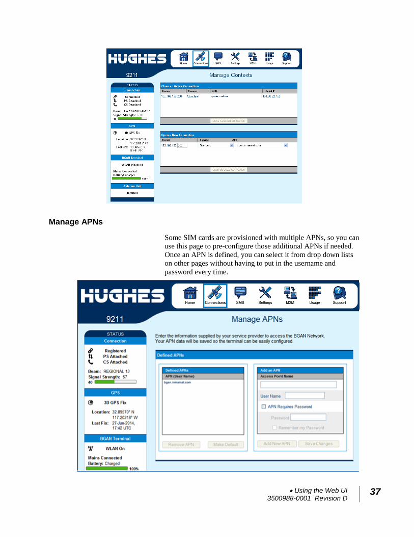
To see if the context has been setup properly, click on the
Connections tab>Manage Contexts Page and this will show
you all contexts that have been setup (active or inactive).
Using the Web UI 3500988-0001 Revision D
37
Manage APNs
Some SIM cards are provisioned with multiple APNs, so you can
use this page to pre-configure those additional APNs if needed.
Once an APN is defined, you can select it from drop down lists
on other pages without having to put in the username and
password every time.
38 Using the Web UI 3500988-0001 Revision D
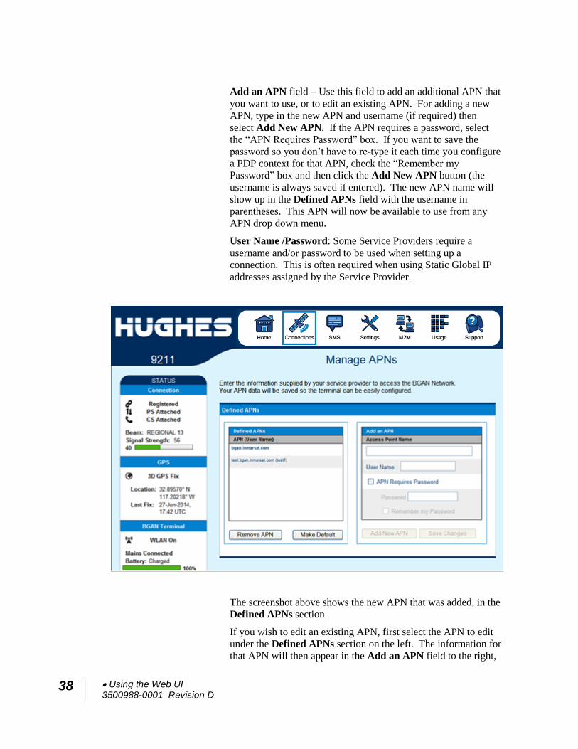
Add an APN field – Use this field to add an additional APN that
you want to use, or to edit an existing APN. For adding a new
APN, type in the new APN and username (if required) then
select Add New APN. If the APN requires a password, select
the “APN Requires Password” box. If you want to save the
password so you don’t have to re-type it each time you configure
a PDP context for that APN, check the “Remember my
Password” box and then click the Add New APN button (the
username is always saved if entered). The new APN name will
show up in the Defined APNs field with the username in
parentheses. This APN will now be available to use from any
APN drop down menu.
User Name /Password: Some Service Providers require a
username and/or password to be used when setting up a
connection. This is often required when using Static Global IP
addresses assigned by the Service Provider.
The screenshot above shows the new APN that was added, in the
Defined APNs section.
If you wish to edit an existing APN, first select the APN to edit
under the Defined APNs section on the left. The information for
that APN will then appear in the Add an APN field to the right,
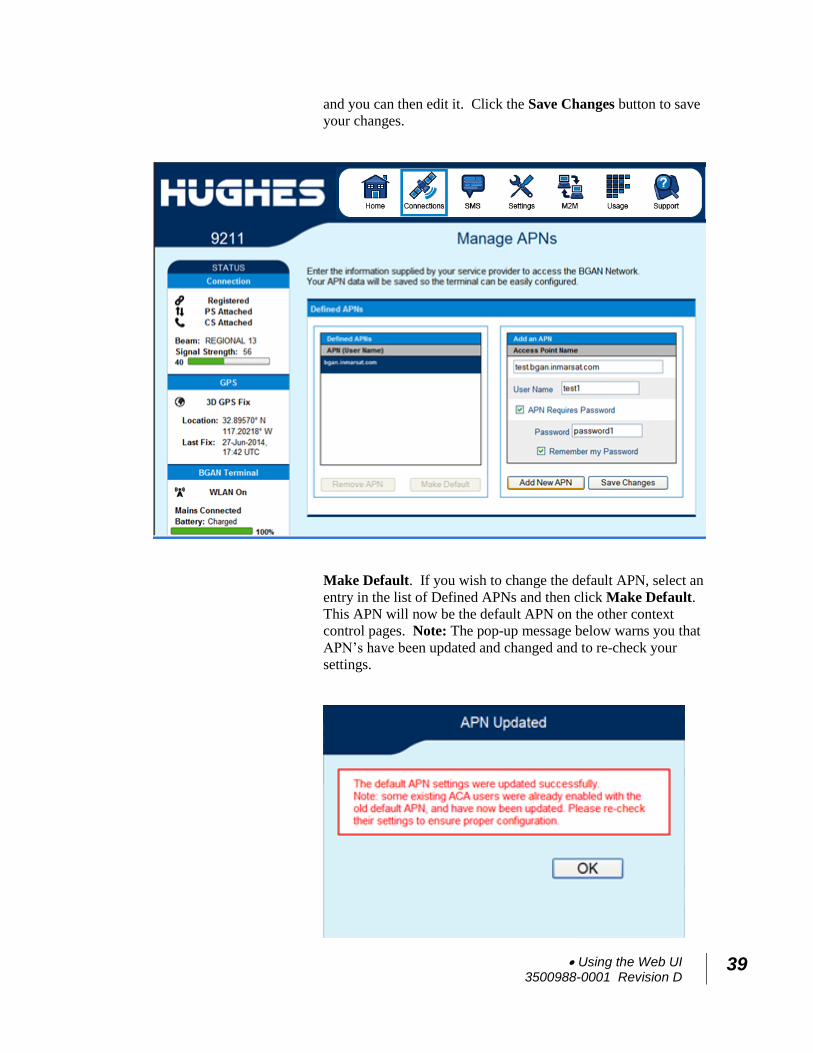
Using the Web UI 3500988-0001 Revision D
39
and you can then edit it. Click the Save Changes button to save
your changes.
Make Default. If you wish to change the default APN, select an
entry in the list of Defined APNs and then click Make Default.
This APN will now be the default APN on the other context
control pages. Note: The pop-up message below warns you that
APN’s have been updated and changed and to re-check your
settings.
40 Using the Web UI 3500988-0001 Revision D
SMS
You can manage SMS text messages from the SMS pages. You
must have a valid Service Center number configured in order to
send SMS messages – see the SMS Settings Page.
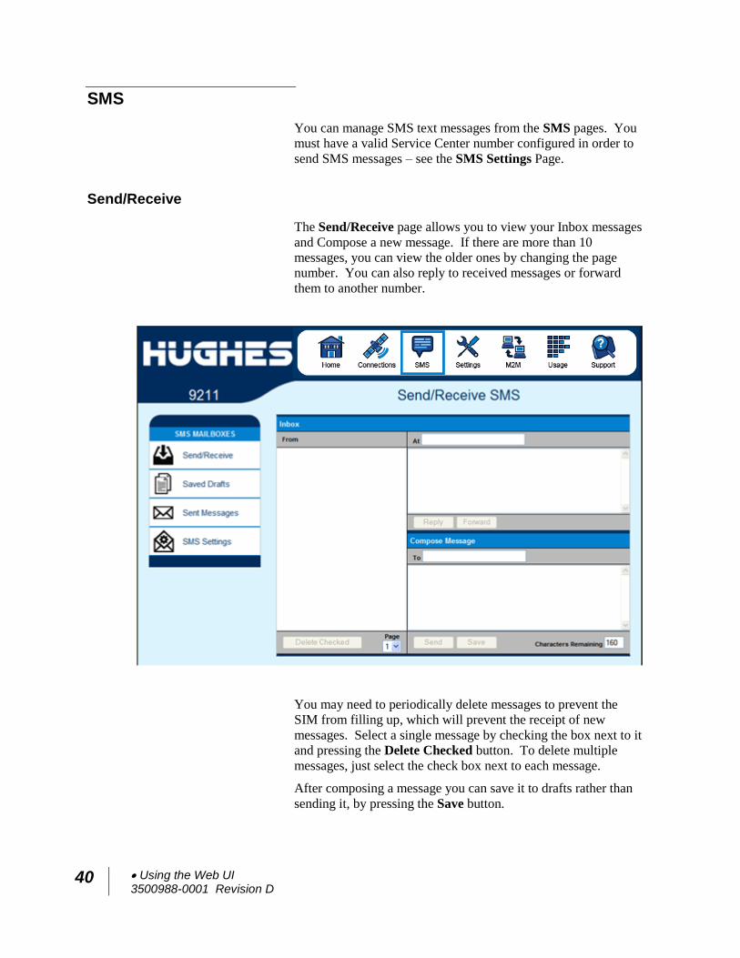
Send/Receive
The Send/Receive page allows you to view your Inbox messages
and Compose a new message. If there are more than 10
messages, you can view the older ones by changing the page
number. You can also reply to received messages or forward
them to another number.
You may need to periodically delete messages to prevent the
SIM from filling up, which will prevent the receipt of new
messages. Select a single message by checking the box next to it
and pressing the Delete Checked button. To delete multiple
messages, just select the check box next to each message.
After composing a message you can save it to drafts rather than
sending it, by pressing the Save button.
Using the Web UI 3500988-0001 Revision D
41
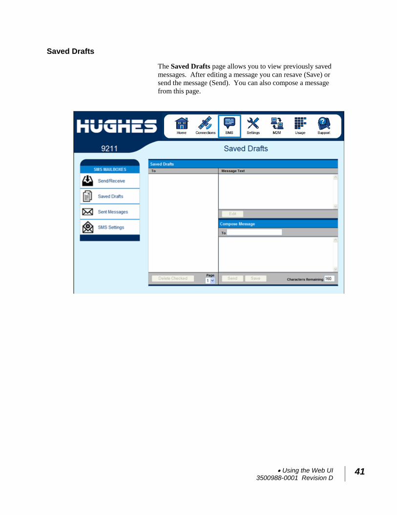
Saved Drafts
The Saved Drafts page allows you to view previously saved
messages. After editing a message you can resave (Save) or
send the message (Send). You can also compose a message
from this page.
42 Using the Web UI 3500988-0001 Revision D
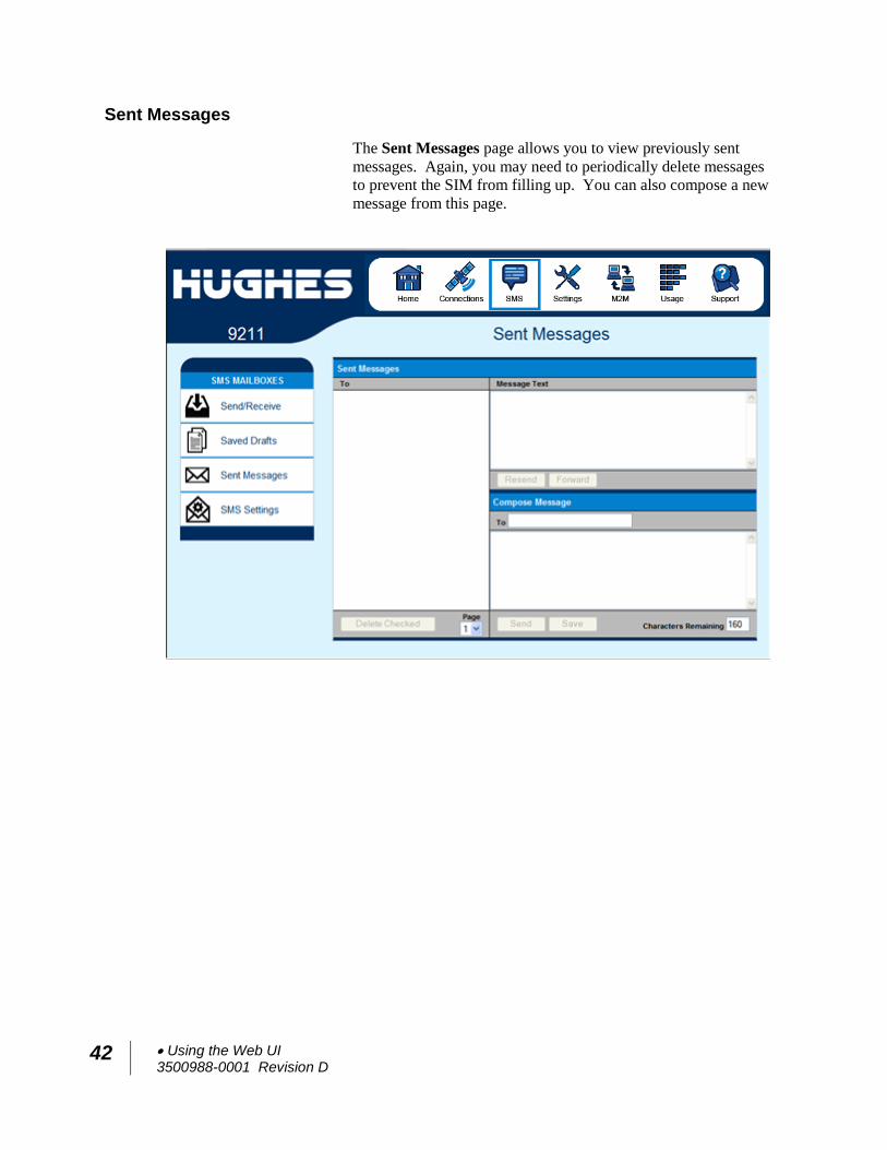
Sent Messages
The Sent Messages page allows you to view previously sent
messages. Again, you may need to periodically delete messages
to prevent the SIM from filling up. You can also compose a new
message from this page.
Using the Web UI 3500988-0001 Revision D
43
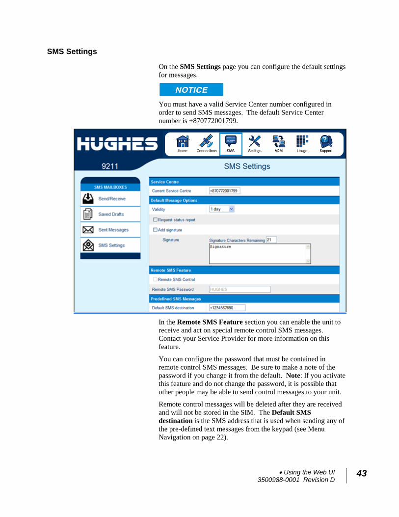
SMS Settings
On the SMS Settings page you can configure the default settings
for messages.
You must have a valid Service Center number configured in
order to send SMS messages. The default Service Center
number is +870772001799.
In the Remote SMS Feature section you can enable the unit to
receive and act on special remote control SMS messages.
Contact your Service Provider for more information on this
feature.
You can configure the password that must be contained in
remote control SMS messages. Be sure to make a note of the
password if you change it from the default. Note: If you activate
this feature and do not change the password, it is possible that
other people may be able to send control messages to your unit.
Remote control messages will be deleted after they are received
and will not be stored in the SIM. The Default SMS
destination is the SMS address that is used when sending any of
the pre-defined text messages from the keypad (see Menu
Navigation on page 22).
44 Using the Web UI 3500988-0001 Revision D
Settings page
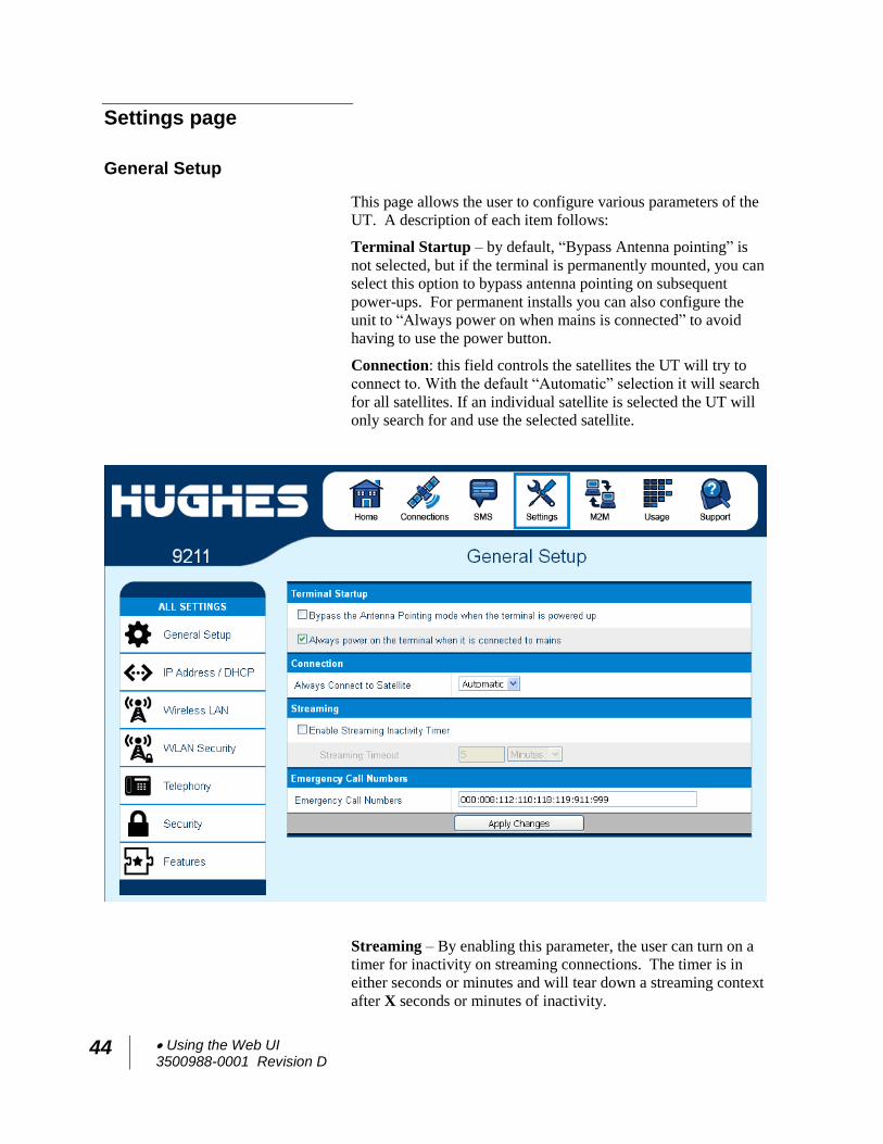
General Setup
This page allows the user to configure various parameters of the
UT. A description of each item follows:
Terminal Startup – by default, “Bypass Antenna pointing” is
not selected, but if the terminal is permanently mounted, you can
select this option to bypass antenna pointing on subsequent
power-ups. For permanent installs you can also configure the
unit to “Always power on when mains is connected” to avoid
having to use the power button.
Connection: this field controls the satellites the UT will try to
connect to. With the default “Automatic” selection it will search
for all satellites. If an individual satellite is selected the UT will
only search for and use the selected satellite.
Streaming – By enabling this parameter, the user can turn on a
timer for inactivity on streaming connections. The timer is in
either seconds or minutes and will tear down a streaming context
after X seconds or minutes of inactivity.
Using the Web UI 3500988-0001 Revision D
45
Emergency Call Numbers: Allows the user to add the
emergency call number that is applicable in the part of the world
where the terminal is being used, if it is not already defined.
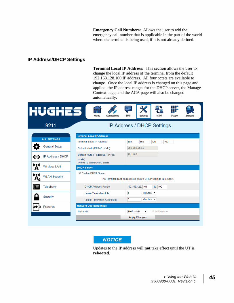
IP Address/DHCP Settings
Terminal Local IP Address: This section allows the user to
change the local IP address of the terminal from the default
192.168.128.100 IP address. All four octets are available to
change. Once the local IP address is changed on this page and
applied, the IP address ranges for the DHCP server, the Manage
Context page, and the ACA page will also be changed
automatically.
Updates to the IP address will not take effect until the UT is
rebooted.
46 Using the Web UI 3500988-0001 Revision D
Subnet Mask Range: (release 6.0.0.5) only used in PPPoE
mode. If two BGAN terminals are connected to the NSD, set to
255.255.255.128
Default route IP address: (release 6.0.0.5) only used in PPPoE
mode. Use with the NSD when the TE local subnet is different
from the UT subnet.
DHCP Server: allows the DHCP server in the UT to be turned
on or off by checking the “Enable” box.
DHCP Address Range: This allows the user to set the range of
DHCP addresses that are given out by the UT to connected TEs.
Lease Time when Idle: The Idle-mode DHCP Lease Time
refers to the DHCP lease time when the UT is not connected to
the network. This parameter allows the user to change the
default time (60 seconds) that the DHCP lease to the TE is good
for. This parameter was introduced because of problems with
some devices that will not accept a short DHCP lease time.
The longer the Idle-mode DHCP lease time, the longer it will
take the network/UT to update the TE with the correct DNS
servers for web browsing after establishing a data context.
Lease Time when Connected: The Connected-mode DHCP
Lease Time refers to the DHCP lease time when the UT is
connected to the network. Most users will have no need to
change this parameter.
Network Operating Mode: The Netmode field indicates the
mode of operation of the terminal. In NAT Mode, the UT will
translate between the local and global IP addresses. In Relay
Mode, the UT will supply the global IP address to the TE once a
PDP Context is established. Relay Mode is single user/single
PDP Context mode, and only supports a single connected TE. In
6.0.0.4 and above, NAPT Mode is also available; see below. In
6.0.0.5 and above PPPoE is added, see below. Note: Updates to
this field will not take effect until the UT is restarted.
Nat Mode
In NAT mode, once a PDP context is active, the UT will
translate between the local and global IP addresses. This is a
basic NAT that only performs IP address translation. It does not
use port translation.
Using the Web UI 3500988-0001 Revision D
47
Relay Mode
In Relay mode, the UT will supply the global IP address to the
TE when the context is established. Relay mode is a single user
mode, as it only supports a single connected TE.
In Relay mode, DHCP is required to provide the global IP
address to the TE. When the context is activated, the DHCP
server in the UT will NACK the next DHCP lease renewal from
the TE and assign the global IP address assigned by the network.
The local IP connection will be torn down and reestablished as
the IP address changes. Similarly, when the context is
deactivated, the DHCP server will NACK the lease renewal and
then reassign the original private IP address.
LaunchPad and the Web UI will lose and reestablish their
connections to the terminal as the IP address is changed.
To make the IP address change happen quickly, a short DHCP
lease should be used. The terminal defaults the DHCP lease
time to 60 seconds in idle and connected mode.
Relay mode only supports a single user TE.
NAPT Mode
In NAPT mode (6.0.0.4 and above), multiple devices connected
via a hub or switch share a single PDP context. The port
translating NAT modifies both IP addresses and port numbers so
multiple devices can share the single global IP address assigned
to the PDP context.
In NAPT mode, only a single context is supported. By default,
an Always On Context is activated. The ACA page is removed.
A Port Forwarding page is added under Settings, and it can be
used to configure the DMZ and Port Forwarding parameters.
PPPoE Mode
In PPPoE mode (release 6.0.0.5 and above) the UT uses PPP
over Ethernet to communicate with the TEs. PPP sessions are
mapped to PDP contexts. PPPoE mode is primarily designed to
operate as a backup path for the Inmarsat Network Service
Device (NSD). Refer to the Inmarsat NSD documentation for
details.
The NSD requires the UT to be configured for 10BaseT Full
Duplex. Select the NSD mode check box when using PPPoE
mode with an NSD. If PPPoE is used with another device not
hard configured for full duplex, leave the box unchecked.
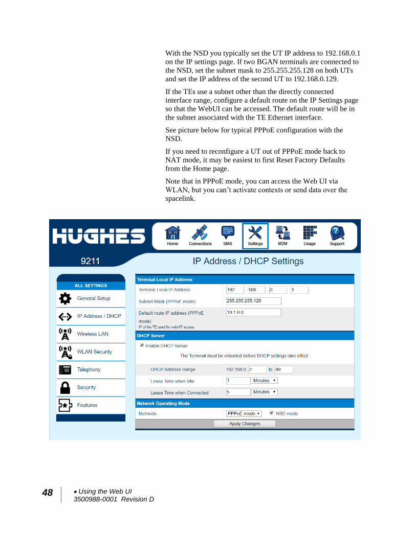
48 Using the Web UI 3500988-0001 Revision D
With the NSD you typically set the UT IP address to 192.168.0.1
on the IP settings page. If two BGAN terminals are connected to
the NSD, set the subnet mask to 255.255.255.128 on both UTs
and set the IP address of the second UT to 192.168.0.129.
If the TEs use a subnet other than the directly connected
interface range, configure a default route on the IP Settings page
so that the WebUI can be accessed. The default route will be in
the subnet associated with the TE Ethernet interface.
See picture below for typical PPPoE configuration with the
NSD.
If you need to reconfigure a UT out of PPPoE mode back to
NAT mode, it may be easiest to first Reset Factory Defaults
from the Home page.
Note that in PPPoE mode, you can access the Web UI via
WLAN, but you can’t activate contexts or send data over the
spacelink.
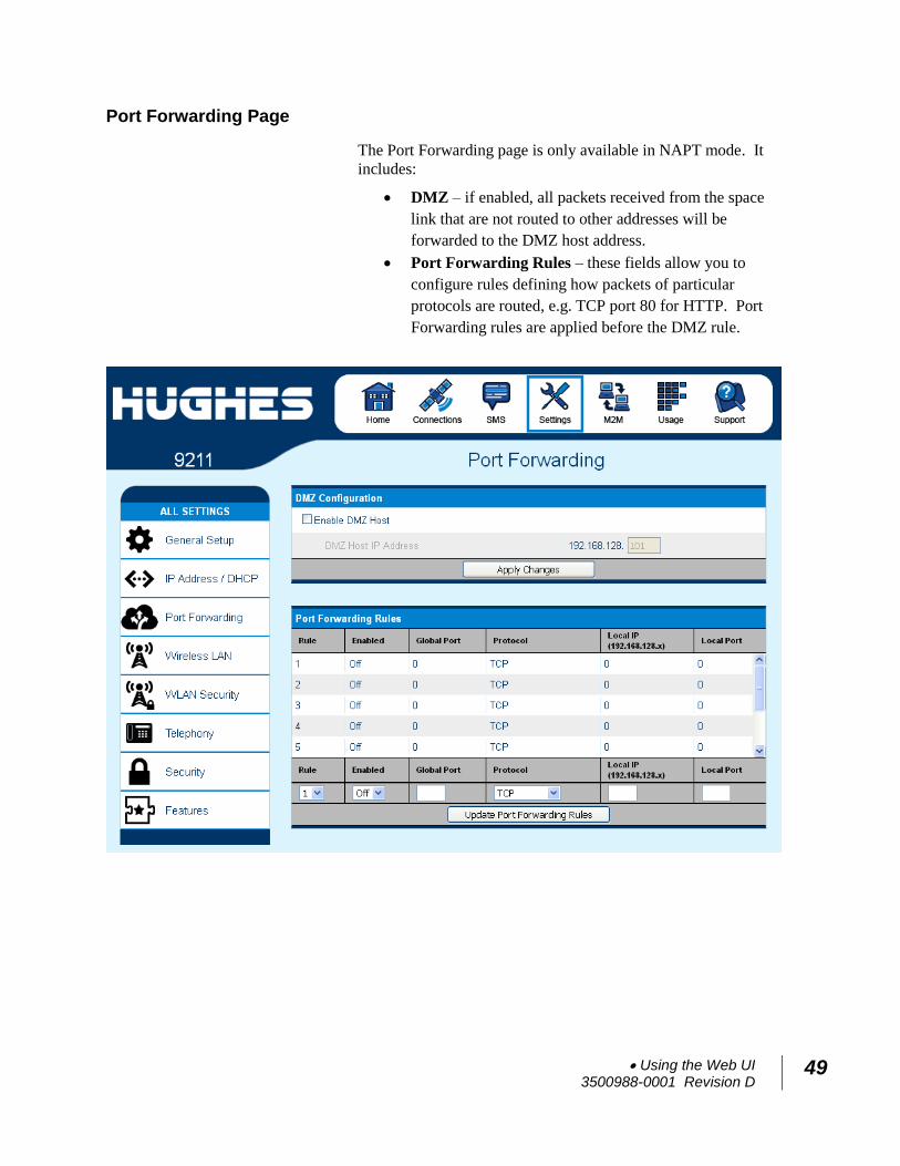
Using the Web UI 3500988-0001 Revision D
49
Port Forwarding Page
The Port Forwarding page is only available in NAPT mode. It
includes:
DMZ – if enabled, all packets received from the space
link that are not routed to other addresses will be
forwarded to the DMZ host address.
Port Forwarding Rules – these fields allow you to
configure rules defining how packets of particular
protocols are routed, e.g. TCP port 80 for HTTP. Port
Forwarding rules are applied before the DMZ rule.
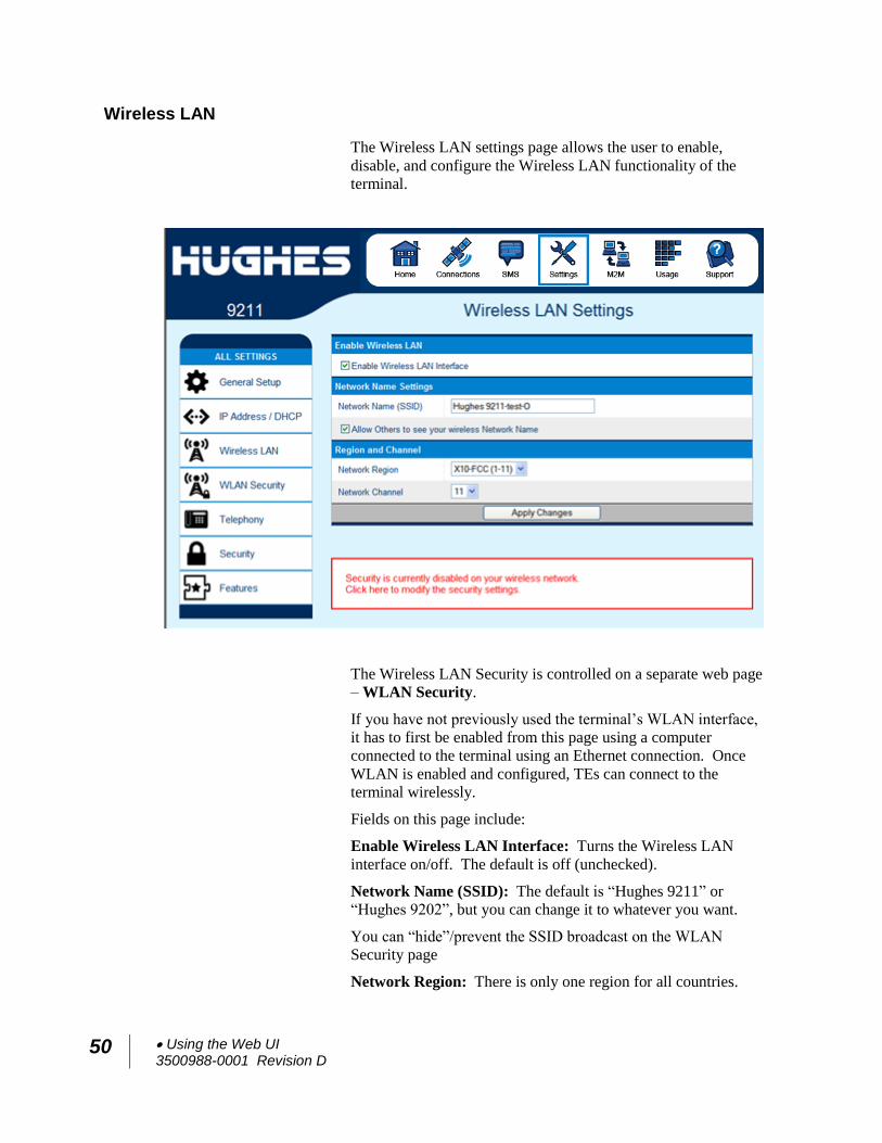
50 Using the Web UI 3500988-0001 Revision D
Wireless LAN
The Wireless LAN settings page allows the user to enable,
disable, and configure the Wireless LAN functionality of the
terminal.
The Wireless LAN Security is controlled on a separate web page
– WLAN Security.
If you have not previously used the terminal’s WLAN interface,
it has to first be enabled from this page using a computer
connected to the terminal using an Ethernet connection. Once
WLAN is enabled and configured, TEs can connect to the
terminal wirelessly.
Fields on this page include:
Enable Wireless LAN Interface: Turns the Wireless LAN
interface on/off. The default is off (unchecked).
Network Name (SSID): The default is “Hughes 9211” or
“Hughes 9202”, but you can change it to whatever you want.
You can “hide”/prevent the SSID broadcast on the WLAN
Security page
Network Region: There is only one region for all countries.
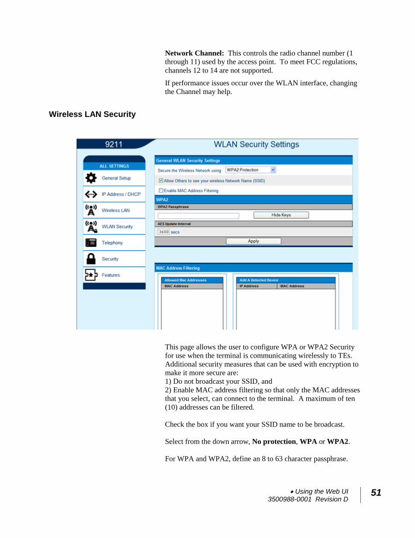
Using the Web UI 3500988-0001 Revision D
51
Network Channel: This controls the radio channel number (1
through 11) used by the access point. To meet FCC regulations,
channels 12 to 14 are not supported.
If performance issues occur over the WLAN interface, changing
the Channel may help.
Wireless LAN Security
This page allows the user to configure WPA or WPA2 Security
for use when the terminal is communicating wirelessly to TEs.
Additional security measures that can be used with encryption to
make it more secure are:
1) Do not broadcast your SSID, and
2) Enable MAC address filtering so that only the MAC addresses
that you select, can connect to the terminal. A maximum of ten
(10) addresses can be filtered.
Check the box if you want your SSID name to be broadcast.
Select from the down arrow, No protection, WPA or WPA2.
For WPA and WPA2, define an 8 to 63 character passphrase.
52 Using the Web UI 3500988-0001 Revision D
MAC Address Filtering
Check the box to Enable MAC Address Filtering
If any TE is already connected to the terminal wirelessly, the
MAC address of that TE will be detected and show up in the
Add a Detected Device field.
To add the detected MAC address, click on the address to
highlight it and then click Add. It will now show up in the
Allowed MAC Address field.
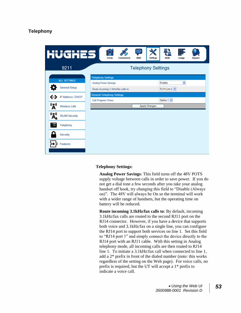
Using the Web UI 3500988-0001 Revision D
53
Telephony
Telephony Settings:
Analog Power Savings: This field turns off the 48V POTS
supply voltage between calls in order to save power. If you do
not get a dial tone a few seconds after you take your analog
handset off hook, try changing this field to “Disable (Always
on)”. The 48V will always be On so the terminal will work
with a wider range of handsets, but the operating time on
battery will be reduced.
Route incoming 3.1kHz/fax calls to: By default, incoming
3.1kHz/fax calls are routed to the second RJ11 port on the
RJ14 connector. However, if you have a device that supports
both voice and 3.1kHz/fax on a single line, you can configure
the RJ14 port to support both services on line 1. Set this field
to “RJ14 port 1” and simply connect the device directly to the
RJ14 port with an RJ11 cable. With this setting in Analog
telephony mode, all incoming calls are then routed to RJ14
line 1. To initiate a 3.1kHz/fax call when connected to line 1,
add a 2* prefix in front of the dialed number (note: this works
regardless of the setting on the Web page). For voice calls, no
prefix is required, but the UT will accept a 1* prefix to
indicate a voice call.
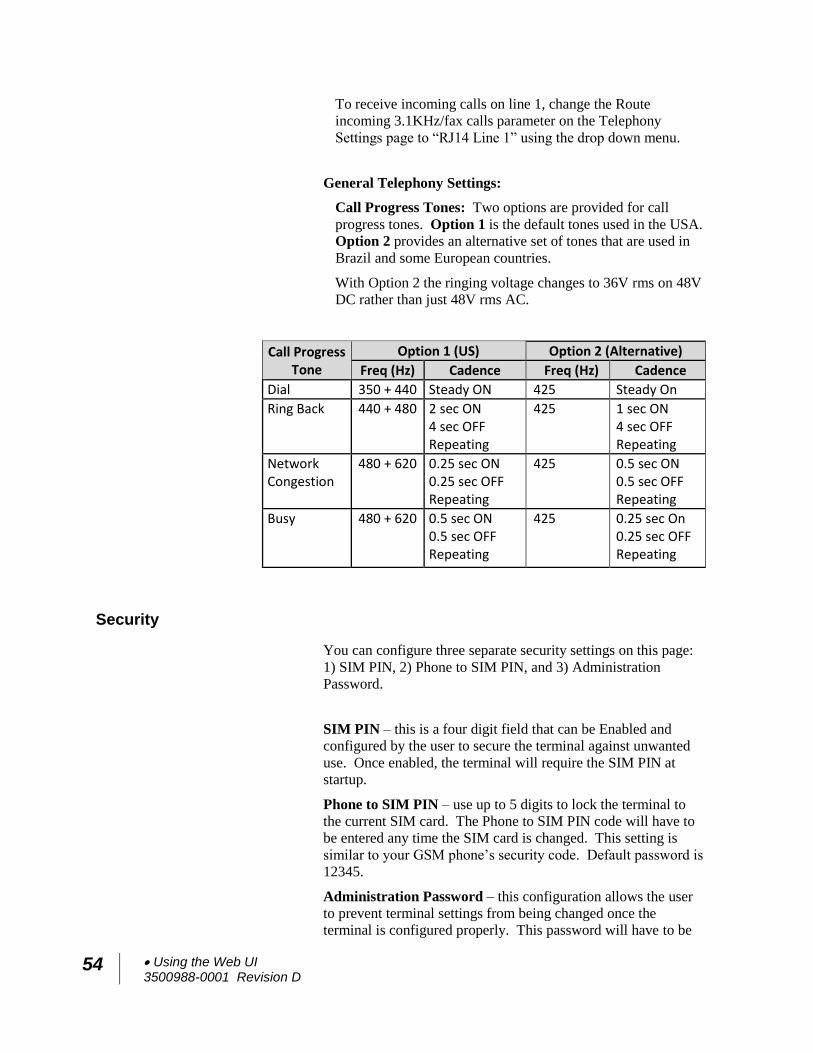
54 Using the Web UI 3500988-0001 Revision D
To receive incoming calls on line 1, change the Route
incoming 3.1KHz/fax calls parameter on the Telephony
Settings page to “RJ14 Line 1” using the drop down menu.
General Telephony Settings:
Call Progress Tones: Two options are provided for call
progress tones. Option 1 is the default tones used in the USA.
Option 2 provides an alternative set of tones that are used in
Brazil and some European countries.
With Option 2 the ringing voltage changes to 36V rms on 48V
DC rather than just 48V rms AC.
Call Progress Tone
Option 1 (US) Option 2 (Alternative)
Freq (Hz) Cadence Freq (Hz) Cadence
Dial 350 + 440 Steady ON 425 Steady On
Ring Back 440 + 480 2 sec ON 4 sec OFF Repeating
425 1 sec ON 4 sec OFF Repeating
Network Congestion
480 + 620 0.25 sec ON 0.25 sec OFF Repeating
425 0.5 sec ON 0.5 sec OFF Repeating
Busy 480 + 620 0.5 sec ON 0.5 sec OFF Repeating
425 0.25 sec On 0.25 sec OFF Repeating
Security
You can configure three separate security settings on this page:
1) SIM PIN, 2) Phone to SIM PIN, and 3) Administration
Password.
SIM PIN – this is a four digit field that can be Enabled and
configured by the user to secure the terminal against unwanted
use. Once enabled, the terminal will require the SIM PIN at
startup.
Phone to SIM PIN – use up to 5 digits to lock the terminal to
the current SIM card. The Phone to SIM PIN code will have to
be entered any time the SIM card is changed. This setting is
similar to your GSM phone’s security code. Default password is
12345.
Administration Password – this configuration allows the user
to prevent terminal settings from being changed once the
terminal is configured properly. This password will have to be
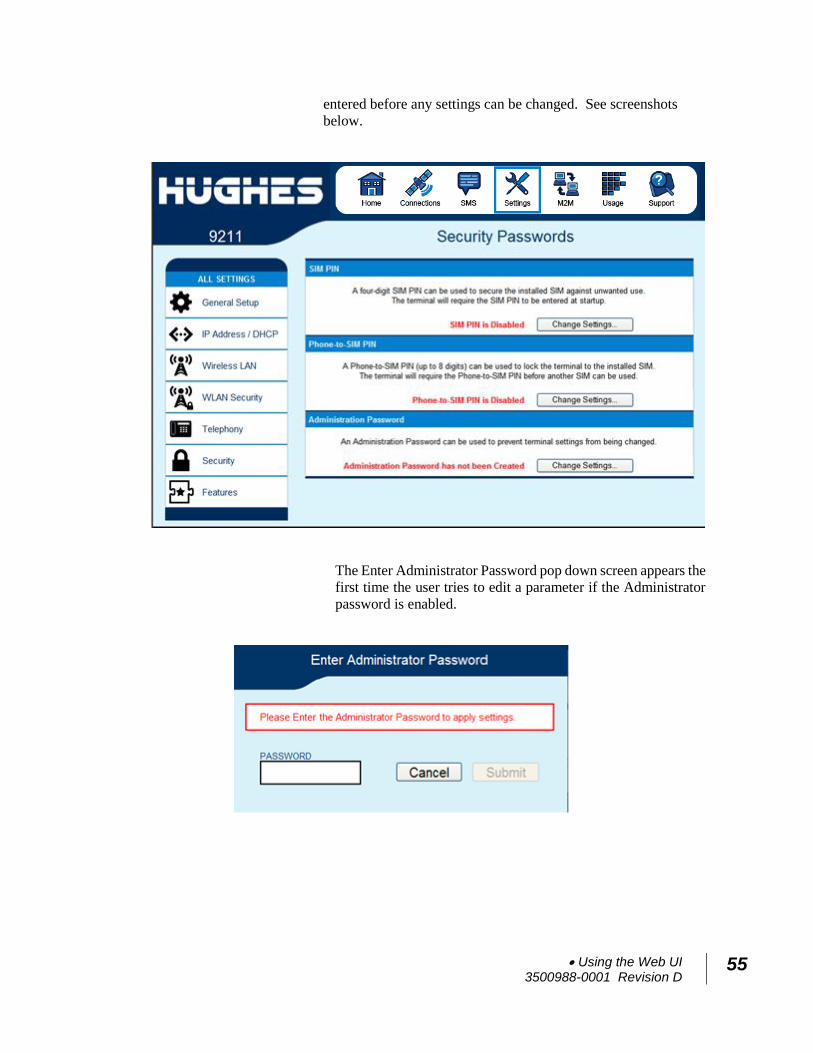
Using the Web UI 3500988-0001 Revision D
55
entered before any settings can be changed. See screenshots
below.
The Enter Administrator Password pop down screen appears the
first time the user tries to edit a parameter if the Administrator
password is enabled.
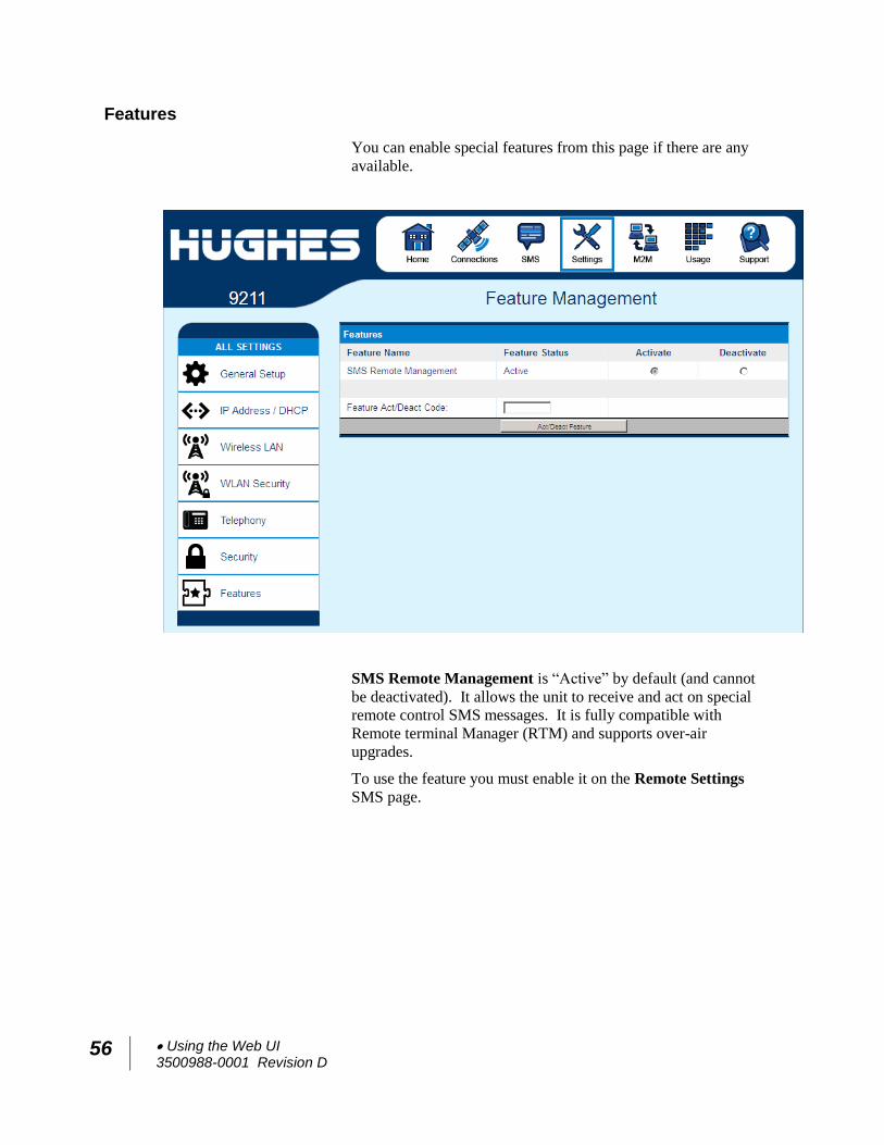
56 Using the Web UI 3500988-0001 Revision D
Features
You can enable special features from this page if there are any
available.
SMS Remote Management is “Active” by default (and cannot
be deactivated). It allows the unit to receive and act on special
remote control SMS messages. It is fully compatible with
Remote terminal Manager (RTM) and supports over-air
upgrades.
To use the feature you must enable it on the Remote Settings
SMS page.
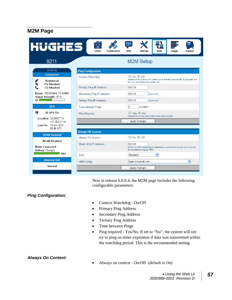
Using the Web UI 3500988-0001 Revision D
57
M2M Page
New in release 6.0.0.4, the M2M page includes the following
configurable parameters:
Ping Configuration:
Context Watchdog - On/Off
Primary Ping Address
Secondary Ping Address
Tertiary Ping Address
Time between Pings
Ping required - Yes/No. If set to “No”, the system will not
try to ping on timer expiration if data was transmitted within
the watchdog period. This is the recommended setting.
Always On Context:
Always on context - On/Off (default is On)
58 Using the Web UI 3500988-0001 Revision D
Always on static IP address. If the TE has a known static IP
address or never ARPs, enter this address. Alternatively,
leave the IP address blank (0.0.0.0) and the UT will set up a
context for the first device it detects through ARP during
startup.
APN drop down box
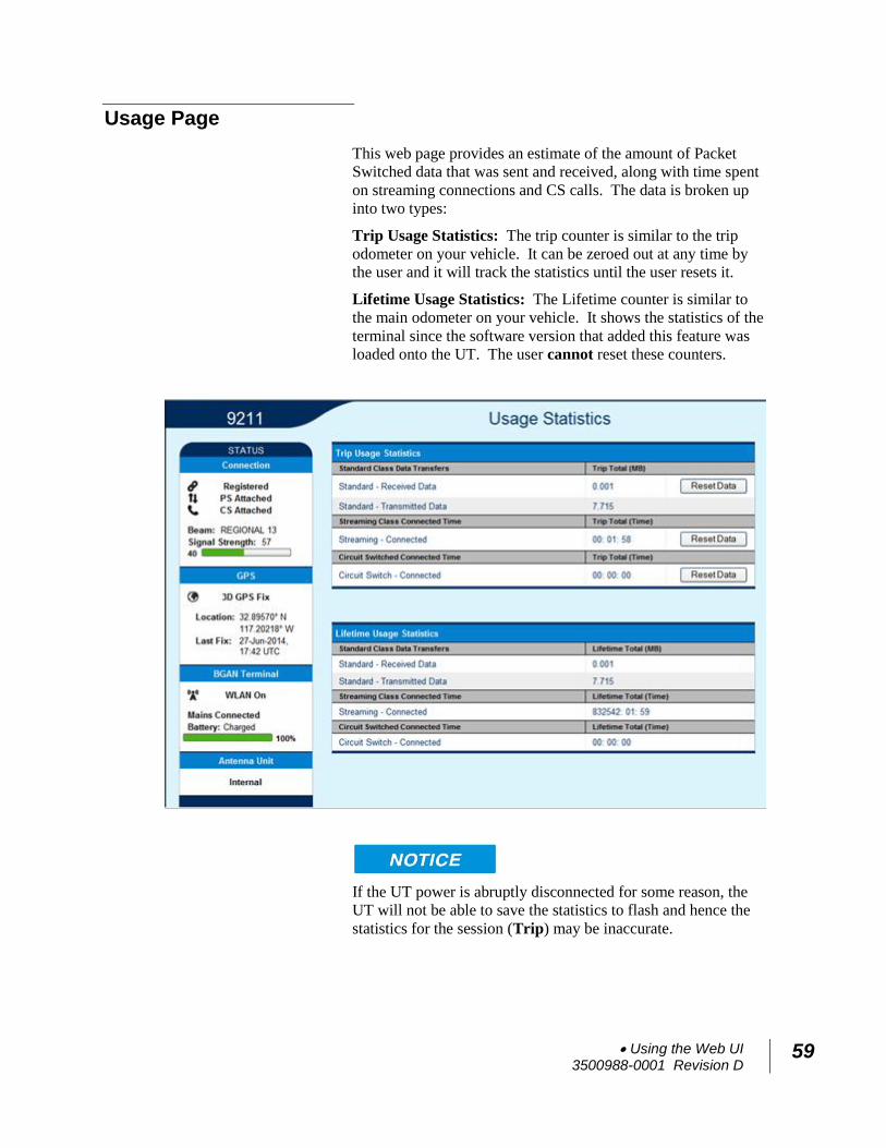
Using the Web UI 3500988-0001 Revision D
59
Usage Page
This web page provides an estimate of the amount of Packet
Switched data that was sent and received, along with time spent
on streaming connections and CS calls. The data is broken up
into two types:
Trip Usage Statistics: The trip counter is similar to the trip
odometer on your vehicle. It can be zeroed out at any time by
the user and it will track the statistics until the user resets it.
Lifetime Usage Statistics: The Lifetime counter is similar to
the main odometer on your vehicle. It shows the statistics of the
terminal since the software version that added this feature was
loaded onto the UT. The user cannot reset these counters.
If the UT power is abruptly disconnected for some reason, the
UT will not be able to save the statistics to flash and hence the
statistics for the session (Trip) may be inaccurate.
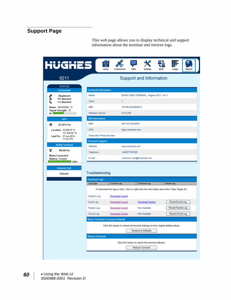
60 Using the Web UI 3500988-0001 Revision D
Support Page
This web page allows you to display technical and support
information about the terminal and retrieve logs.
Using the Web UI 3500988-0001 Revision D
61
Support and Information
Terminal Information
Model: this displays the UT model number: 9211 or
9202M.
Class: this indicates the UT Class.
IMEI: This displays the IMEI (serial) number of the
UT.
Software Version: This displays the current version
of software that is running on the UT.
SIM Information
IMSI: This displays the IMSI number of the SIM card
in the UT. If is the IMSI is not displayed, it indicates
that there is a problem reading the SIM card, e.g.
because there is no SIM, it is installed incorrectly or
PIN must be entered.
APN: This is the APN read from the SIM card.
Subscriber Phone Number: this field displays the
MSISDN or phone number for the terminal’s voice
service. The number is only displayed if the number
was configured in the SIM by your Service Provider.
Even if no number is shown, the service may still be
active because this field is just for your information
and is not required for the service to operate.
Terminal Support – contact information retrieved from the
SIM card.
Website
Telephone
Troubleshooting
Terminal Log Files: This allows you to extract and save any
of the following log files for troubleshooting purposes:
System Log
Event Log
Packet Log
Circuit Log
These files can be e-mailed to Hughes directly for fault
analysis if the user experiences any problems.
62 Using the Web UI 3500988-0001 Revision D
Downloading of the terminal log files uses FTP to retrieve the
files from the UT, which can be blocked by some security
software such as McAfee. If you encounter problems, check
your PC security settings.
When extracting files, clear the browser cache on the computer
between each download or the browser may use a cached copy
rather than downloading the latest version of the file.
Downloading files is not supported with the Chrome browser.
Reset Terminal to Factory Defaults: Clicking the “Restore
to Defaults” button will restore the UT back to the factory
default settings and delete any of the user parameters that have
been set-up in the UT, including any custom APN settings.
Hughes highly recommends that the user exhaust all possible
troubleshooting procedures before using this feature
Reboot terminal: Clicking this button reboots the terminal so
that configuration changes can be saved into the configuration
file or it can be used when just a simple reboot of the terminal
is required.
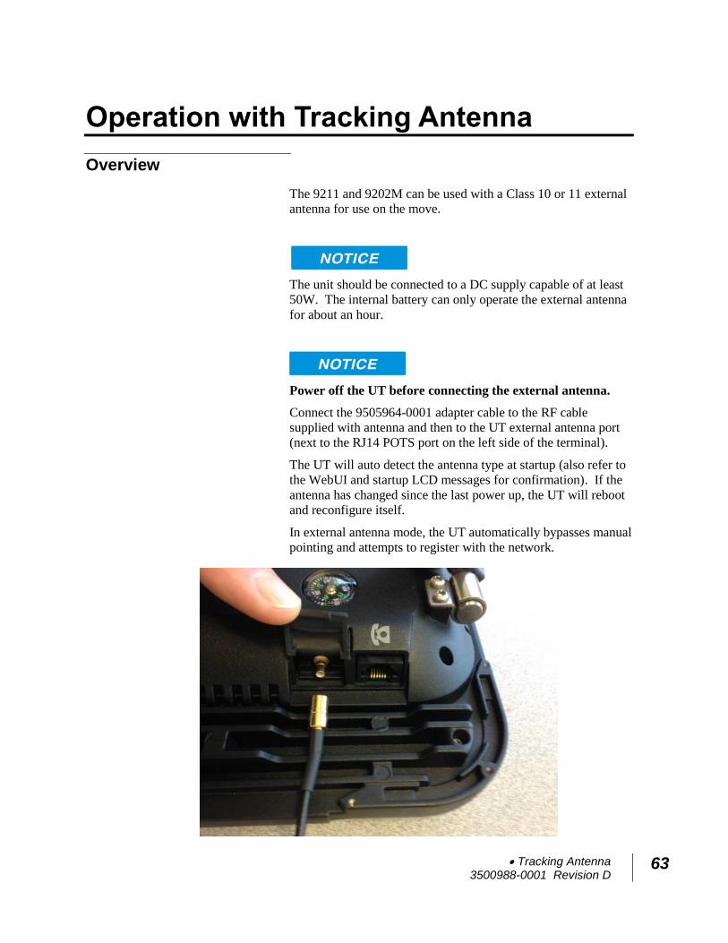
Tracking Antenna 3500988-0001 Revision D
63
Operation with Tracking Antenna
Overview
The 9211 and 9202M can be used with a Class 10 or 11 external
antenna for use on the move.
The unit should be connected to a DC supply capable of at least
50W. The internal battery can only operate the external antenna
for about an hour.
Power off the UT before connecting the external antenna.
Connect the 9505964-0001 adapter cable to the RF cable
supplied with antenna and then to the UT external antenna port
(next to the RJ14 POTS port on the left side of the terminal).
The UT will auto detect the antenna type at startup (also refer to
the WebUI and startup LCD messages for confirmation). If the
antenna has changed since the last power up, the UT will reboot
and reconfigure itself.
In external antenna mode, the UT automatically bypasses manual
pointing and attempts to register with the network.
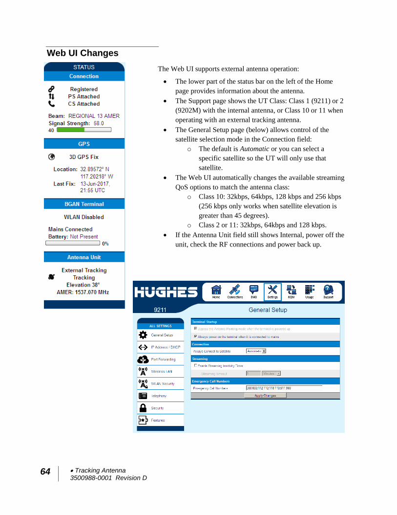
64 Tracking Antenna 3500988-0001 Revision D
Web UI Changes
The Web UI supports external antenna operation:
The lower part of the status bar on the left of the Home
page provides information about the antenna.
The Support page shows the UT Class: Class 1 (9211) or 2
(9202M) with the internal antenna, or Class 10 or 11 when
operating with an external tracking antenna.
The General Setup page (below) allows control of the
satellite selection mode in the Connection field:
o The default is Automatic or you can select a
specific satellite so the UT will only use that
satellite.
The Web UI automatically changes the available streaming
QoS options to match the antenna class:
o Class 10: 32kbps, 64kbps, 128 kbps and 256 kbps
(256 kbps only works when satellite elevation is
greater than 45 degrees).
o Class 2 or 11: 32kbps, 64kbps and 128 kbps.
If the Antenna Unit field still shows Internal, power off the
unit, check the RF connections and power back up.
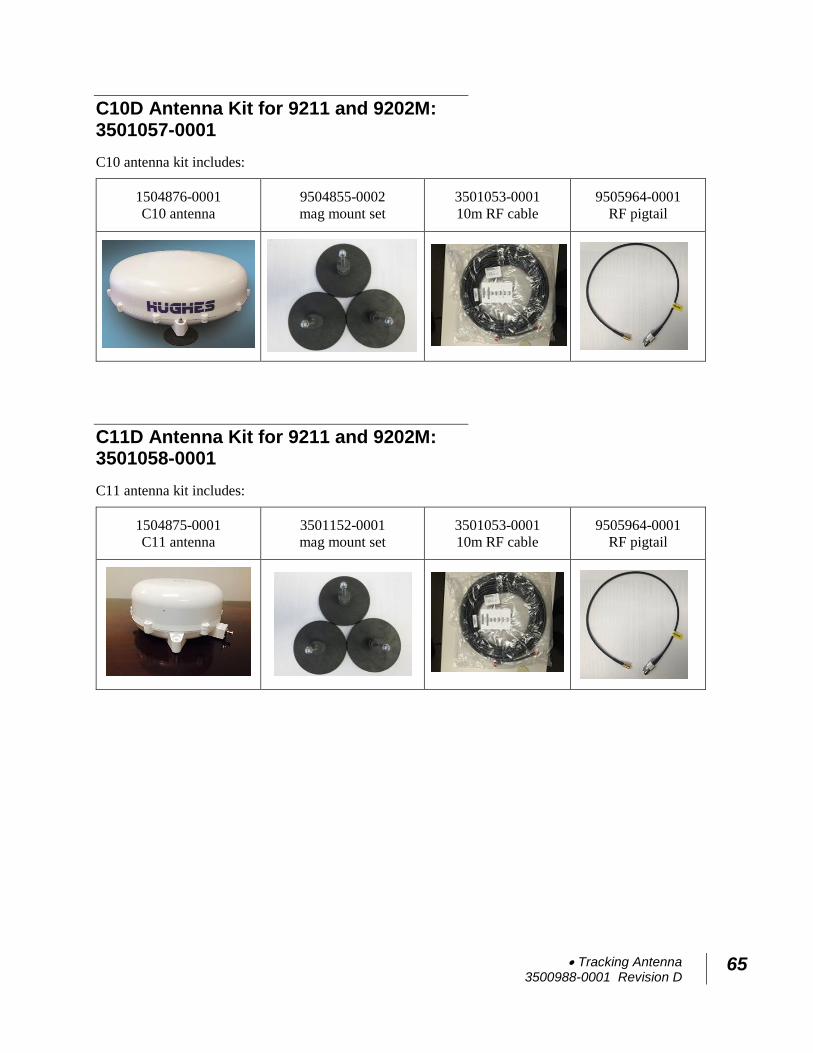
Tracking Antenna 3500988-0001 Revision D
65
C10D Antenna Kit for 9211 and 9202M: 3501057-0001
C10 antenna kit includes:
1504876-0001
C10 antenna 9504855-0002
mag mount set
3501053-0001
10m RF cable
9505964-0001
RF pigtail
C11D Antenna Kit for 9211 and 9202M: 3501058-0001
C11 antenna kit includes:
1504875-0001
C11 antenna 3501152-0001
mag mount set
3501053-0001
10m RF cable
9505964-0001
RF pigtail
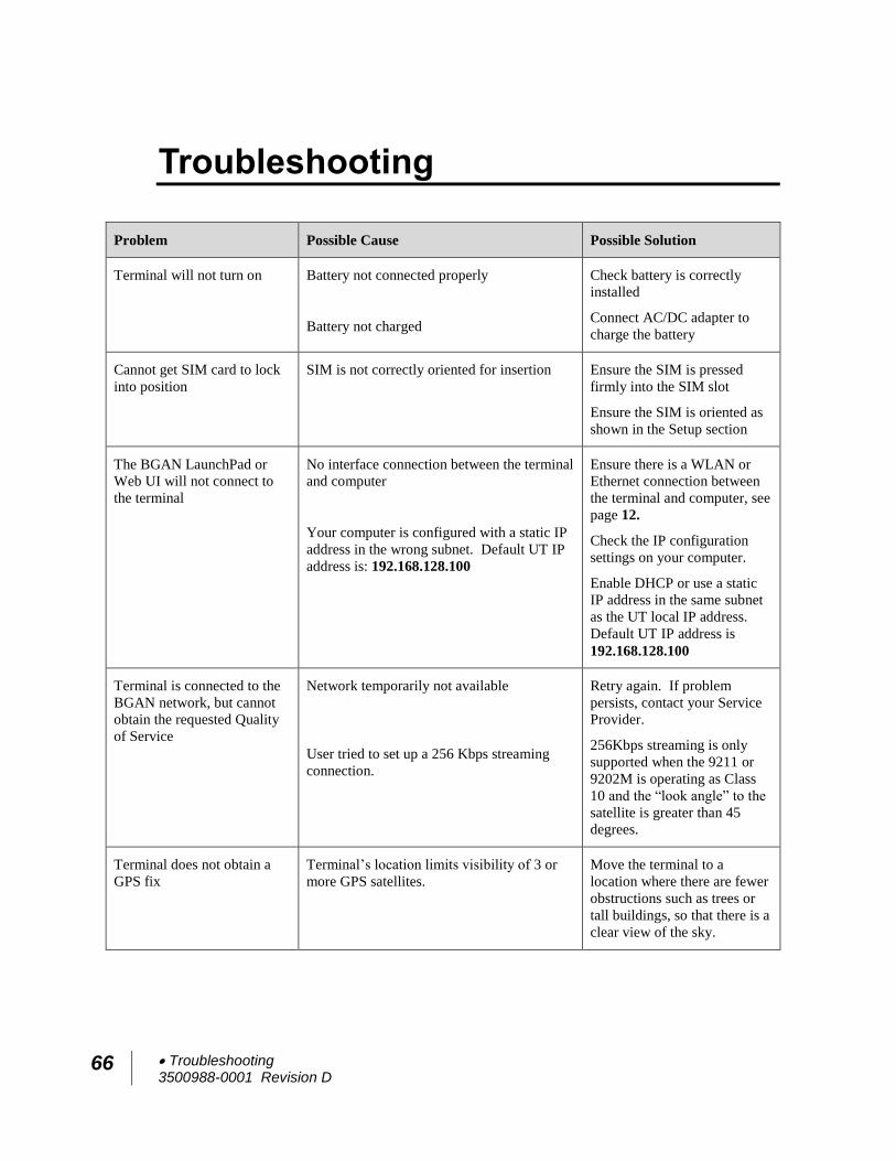
66 Troubleshooting 3500988-0001 Revision D
Troubleshooting
Problem Possible Cause Possible Solution
Terminal will not turn on Battery not connected properly
Battery not charged
Check battery is correctly
installed
Connect AC/DC adapter to
charge the battery
Cannot get SIM card to lock
into position
SIM is not correctly oriented for insertion
Ensure the SIM is pressed
firmly into the SIM slot
Ensure the SIM is oriented as
shown in the Setup section
The BGAN LaunchPad or
Web UI will not connect to
the terminal
No interface connection between the terminal
and computer
Your computer is configured with a static IP
address in the wrong subnet. Default UT IP
address is: 192.168.128.100
Ensure there is a WLAN or
Ethernet connection between
the terminal and computer, see
page 12.
Check the IP configuration
settings on your computer.
Enable DHCP or use a static
IP address in the same subnet
as the UT local IP address.
Default UT IP address is
192.168.128.100
Terminal is connected to the
BGAN network, but cannot
obtain the requested Quality
of Service
Network temporarily not available
User tried to set up a 256 Kbps streaming
connection.
Retry again. If problem
persists, contact your Service
Provider.
256Kbps streaming is only
supported when the 9211 or
9202M is operating as Class
10 and the “look angle” to the
satellite is greater than 45
degrees.
Terminal does not obtain a
GPS fix
Terminal’s location limits visibility of 3 or
more GPS satellites.
Move the terminal to a
location where there are fewer
obstructions such as trees or
tall buildings, so that there is a
clear view of the sky.
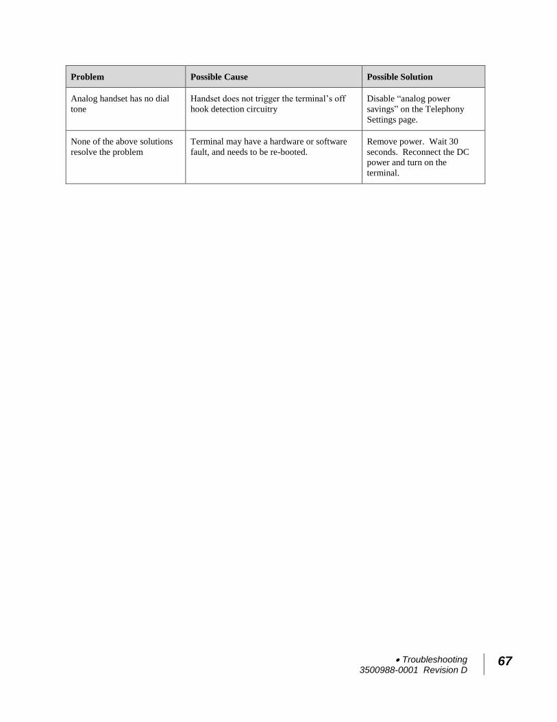
Troubleshooting 3500988-0001 Revision D
67
Problem Possible Cause Possible Solution
Analog handset has no dial
tone
Handset does not trigger the terminal’s off
hook detection circuitry
Disable “analog power
savings” on the Telephony
Settings page.
None of the above solutions
resolve the problem
Terminal may have a hardware or software
fault, and needs to be re-booted.
Remove power. Wait 30
seconds. Reconnect the DC
power and turn on the
terminal.
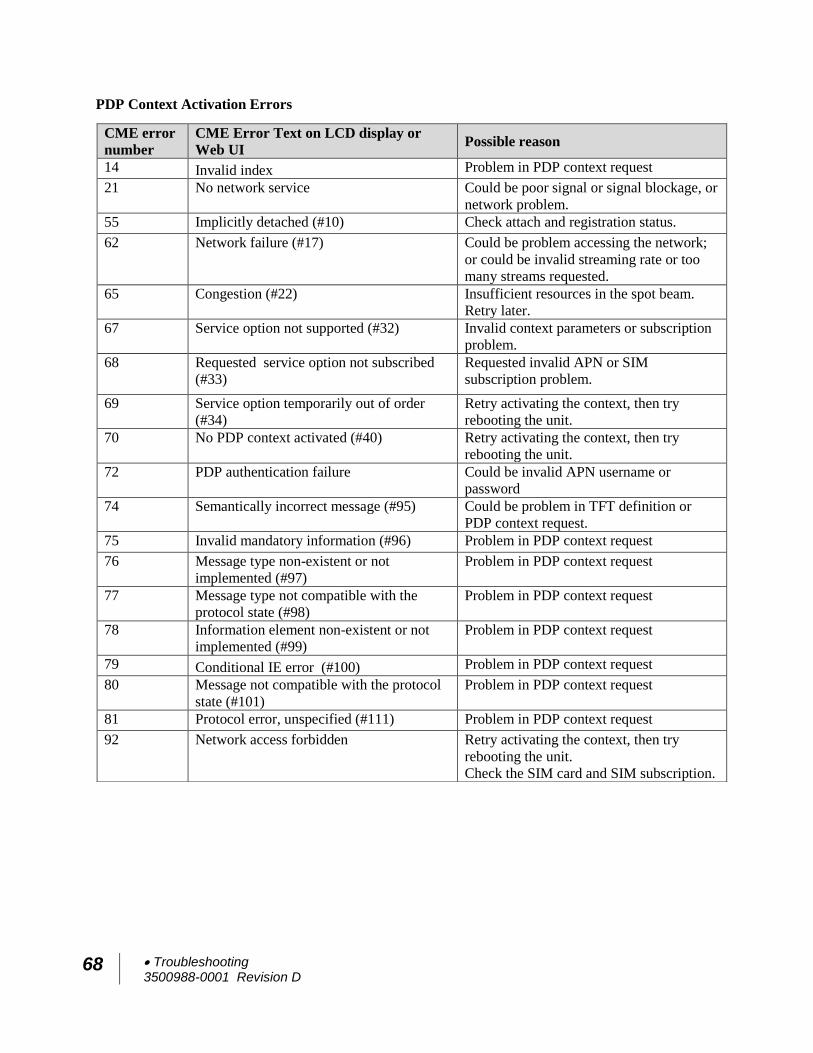
68 Troubleshooting 3500988-0001 Revision D
PDP Context Activation Errors
CME error
number
CME Error Text on LCD display or
Web UI Possible reason
14 Invalid index Problem in PDP context request
21 No network service
Could be poor signal or signal blockage, or
network problem.
55 Implicitly detached (#10) Check attach and registration status.
62 Network failure (#17)
Could be problem accessing the network;
or could be invalid streaming rate or too
many streams requested.
65 Congestion (#22) Insufficient resources in the spot beam.
Retry later.
67 Service option not supported (#32) Invalid context parameters or subscription
problem.
68 Requested service option not subscribed
(#33)
Requested invalid APN or SIM
subscription problem.
69 Service option temporarily out of order
(#34)
Retry activating the context, then try
rebooting the unit.
70 No PDP context activated (#40) Retry activating the context, then try
rebooting the unit.
72 PDP authentication failure Could be invalid APN username or
password
74 Semantically incorrect message (#95) Could be problem in TFT definition or
PDP context request.
75 Invalid mandatory information (#96) Problem in PDP context request
76 Message type non-existent or not
implemented (#97)
Problem in PDP context request
77 Message type not compatible with the
protocol state (#98)
Problem in PDP context request
78 Information element non-existent or not
implemented (#99)
Problem in PDP context request
79 Conditional IE error (#100) Problem in PDP context request
80 Message not compatible with the protocol
state (#101)
Problem in PDP context request
81 Protocol error, unspecified (#111) Problem in PDP context request
92 Network access forbidden Retry activating the context, then try
rebooting the unit.
Check the SIM card and SIM subscription.

Technology Overview 3500988-0001 Revision D
69
Technology Overview
GPS
The Global Positioning System (GPS) uses 24 orbital satellites to
determine the position of the Terminal anywhere on the globe.
Obtaining a GPS Fix
In normal operation, a GPS receiver, such as that built in to the
terminal, needs to be able to receive signals from at least four
satellites so that it can then calculate a latitude, a longitude and
an altitude – this position fix is referred to as a 3-dimensional or
3-D fix. If only three GPS satellites can be seen by the GPS
receiver, then the last available altitude measurement is assumed
and the GPS receiver calculates a position fix based on latitude
and longitude only. This simpler position fix is referred to as a
2-dimensional or 2-D fix and is quicker and easier to obtain than
a 3-D fix, but may be less accurate.
The GPS receiver may take between a few seconds and a few
minutes to obtain a GPS fix, depending on how frequently the
GPS receiver is being used. The frequency of use determines the
how quickly the GPS Terminal is able to start.
Hot start if the GPS receiver is being used frequently, (that
is, in the last two hours), it is regularly updated with data
from the GPS satellites, and so only takes a few seconds to obtain a GPS fix after being switched on.
Warm start if a GPS receiver has not been used for more
than two hours then it may take up to 45 seconds to obtain a GPS fix.
Cold start if the GPS receiver has not been used for some
time or is 300 km or more from where it was last used, it can
take a few minutes to obtain a valid position fix.
The time taken to obtain a valid GPS fix can also be affected by
the visibility that the GPS receiver has of the GPS satellites. The
GPS system is relatively tolerant of atmospheric conditions such
as heavy cloud or rainfall. However, physical blockages, such as
tall buildings or terrain can significantly degrade the ability of
the GPS receiver to obtain a fix. For this reason, ensure that the
GPS receiver has a clear view of as much open sky as possible.
70 Technology Overview 3500988-0001 Revision D
GPS and BGAN Registration
BGAN uses the accurate position and timing information
obtained from GPS to help ensure efficient registration of a
BGAN Terminal with the BGAN network.
Dialing and Numbering
Dialing - As the BGAN numbering system follows the same
pattern as the normal telephone system, dialing is carried out in
exactly the same manner as making a normal telephone call.
The subscriber number is used with the same international and
area codes as any other telephone network. Start the dialed
number with 00 and terminate it with #. If you are calling
another BGAN unit, dial 00 + 870 number plus # to initiate the
call.
Multi-Subscriber Numbering (MSN) - The BGAN SIM card
has a master MS-ISDN number that is used for making voice
calls and sending SMS messages to another BGAN terminal.
PDP Context
A Packet Data Protocol (PDP) Context defines connection
aspects such as routing, Quality of Service (QoS), security and
billing between a mobile user terminal, such as the BGAN
Terminal, and a data network. PDP Contexts are essential to the
General Packet Radio Service (GPRS) system, which is used by
GSM and UMTS-based 3G networks worldwide for transmitting
data.
In order for a user to be able to transfer data across a network, a
PDP Context must be activated in the Terminal and associated
Core Network. The procedure for this is as follows:
1. After registration with the network, the user activates a
PDP Context using an application on the computer or
Terminal, and requests sufficient radio resources (that is,
power and bandwidth) to support the context activation
procedure.
2. Once the resources are allocated, the Terminal sends the
Activate PDP Context request to the Core Network. This
request includes key information about the mobile user's
PDP address (for example an IP address), PDP type (that
is, static or dynamic address) the QoS requested for this
context, the APN of the external network to which
connectivity is requested, the user's identity (IMSI) and
any necessary IP configuration parameters (for example,
security settings).
Technology Overview 3500988-0001 Revision D
71
3. On receiving the Activate PDP Context message, the Core
Network checks the user's subscription record to establish
whether the request is valid. If the request is valid, a
virtual connection is established between the Terminal and
the Core Network, and data transfer can then take place
between the Terminal and the external data network,
within the scope of the current PDP Context. The PDP
Context information is stored in both the Terminal and the
Core Network.
A single Terminal may have multiple PDP Contexts, each with
different QoS profiles. The primary PDP Context is a PDP
Context with default QoS profile attributes and is always
activated first. All other PDP Contexts with the same PDP
Address are secondary PDP Contexts. Secondary PDP Contexts
share the same PDP Address and connect to the same APN but
may have different QoS profiles.
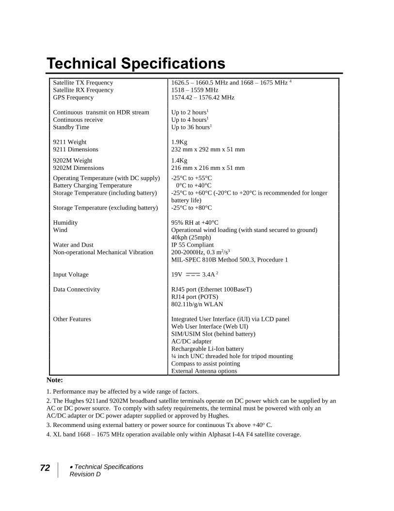
72 Technical Specifications Revision D
Technical Specifications Satellite TX Frequency 1626.5 – 1660.5 MHz and 1668 – 1675 MHz 4
Satellite RX Frequency 1518 – 1559 MHz
GPS Frequency 1574.42 – 1576.42 MHz
Continuous transmit on HDR stream Up to 2 hours1
Continuous receive Up to 4 hours1
Standby Time Up to 36 hours1
9211 Weight 1.9Kg
9211 Dimensions 232 mm x 292 mm x 51 mm
9202M Weight 1.4Kg
9202M Dimensions 216 mm x 216 mm x 51 mm
Operating Temperature (with DC supply) -25°C to +55°C
Battery Charging Temperature 0°C to +40°C
Storage Temperature (including battery) -25°C to +60°C (-20°C to +20°C is recommended for longer
battery life)
Storage Temperature (excluding battery) -25°C to +80°C
Humidity 95% RH at +40°C
Wind Operational wind loading (with stand secured to ground)
40kph (25mph)
Water and Dust IP 55 Compliant
Non-operational Mechanical Vibration 200-2000Hz, 0.3 m2/s3
MIL-SPEC 810B Method 500.3, Procedure 1
Input Voltage 19V 3.4A 2
Data Connectivity RJ45 port (Ethernet 100BaseT)
RJ14 port (POTS)
802.11b/g/n WLAN
Other Features Integrated User Interface (iUI) via LCD panel
Web User Interface (Web UI)
SIM/USIM Slot (behind battery)
AC/DC adapter
Rechargeable Li-Ion battery
¼ inch UNC threaded hole for tripod mounting
Compass to assist pointing
External Antenna options
Note:
1. Performance may be affected by a wide range of factors.
2. The Hughes 9211and 9202M broadband satellite terminals operate on DC power which can be supplied by an
AC or DC power source. To comply with safety requirements, the terminal must be powered with only an
AC/DC adapter or DC power adapter supplied or approved by Hughes.
3. Recommend using external battery or power source for continuous Tx above +40o C.
4. XL band 1668 – 1675 MHz operation available only within Alphasat I-4A F4 satellite coverage.
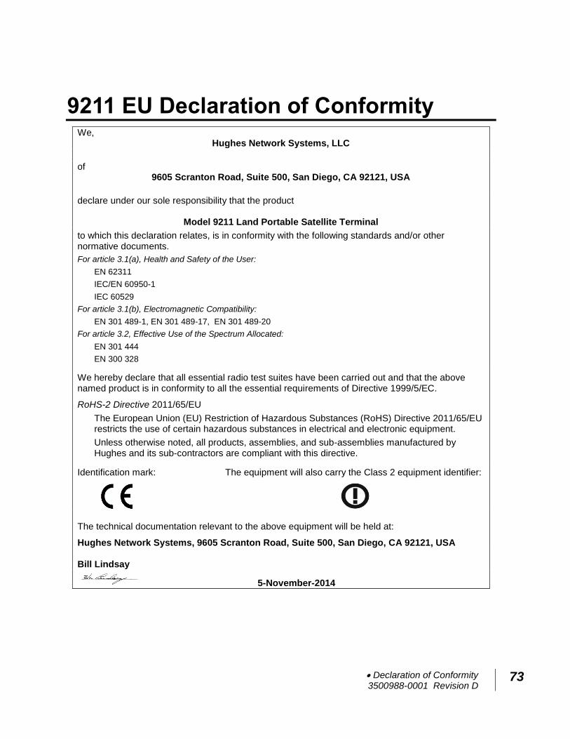
Declaration of Conformity 3500988-0001 Revision D
73
9211 EU Declaration of Conformity We,
Hughes Network Systems, LLC
of 9605 Scranton Road, Suite 500, San Diego, CA 92121, USA
declare under our sole responsibility that the product
Model 9211 Land Portable Satellite Terminal
to which this declaration relates, is in conformity with the following standards and/or other normative documents.
For article 3.1(a), Health and Safety of the User:
EN 62311
IEC/EN 60950-1
IEC 60529
For article 3.1(b), Electromagnetic Compatibility:
EN 301 489-1, EN 301 489-17, EN 301 489-20
For article 3.2, Effective Use of the Spectrum Allocated:
EN 301 444
EN 300 328
We hereby declare that all essential radio test suites have been carried out and that the above named product is in conformity to all the essential requirements of Directive 1999/5/EC.
RoHS-2 Directive 2011/65/EU
The European Union (EU) Restriction of Hazardous Substances (RoHS) Directive 2011/65/EU
restricts the use of certain hazardous substances in electrical and electronic equipment.
Unless otherwise noted, all products, assemblies, and sub-assemblies manufactured by Hughes and its sub-contractors are compliant with this directive.
Identification mark:
The equipment will also carry the Class 2 equipment identifier:
The technical documentation relevant to the above equipment will be held at:
Hughes Network Systems, 9605 Scranton Road, Suite 500, San Diego, CA 92121, USA Bill Lindsay
5-November-2014
74 Declaration of Conformity 3500988-0001 Revision D
FCC Compliance
This device conforms to the FCC rules. Any changes or
modifications to Hughes Network Systems’ equipment, not
expressly approved by Hughes Network Systems, could void
the user's authority to operate the equipment.
To comply with FCC RF exposure requirements, this device
must be operated with a minimum separation distance of one
meter from the front of the satellite terminal’s antenna to a
person's body. Other operating configurations should be
avoided.
This device complies with Part 15 of the FCC Rules.
Operation is subject to the following two conditions; (1) this
device may not cause harmful interference, and (2) this
device must accept any interference received, including
interference that may cause undesired operation.
This equipment has been tested and found to comply with
the limits for a Class B digital device, pursuant to Part 15 of
the FCC Rules. These limits are designed to provide
reasonable protection against harmful interference in a
residential installation. This equipment generates, uses and
can radiate radio frequency energy and, if not installed and
used in accordance with the instructions, may cause harmful
interference to radio communications. However, there is no
guarantee that interference will not occur in a particular
installation. If this equipment does cause harmful
interference to radio or television reception, which can be
determined by turning the equipment off and on, the user is
encouraged to try to correct the interference by one or more
of the following measures:
—Reorient or relocate the receiving antenna.
—Increase the separation between the equipment and
receiver.
—Connect the equipment into an outlet on a circuit different
from that to which the receiver is connected.
—Consult the dealer or an experienced radio/TV technician
for help.
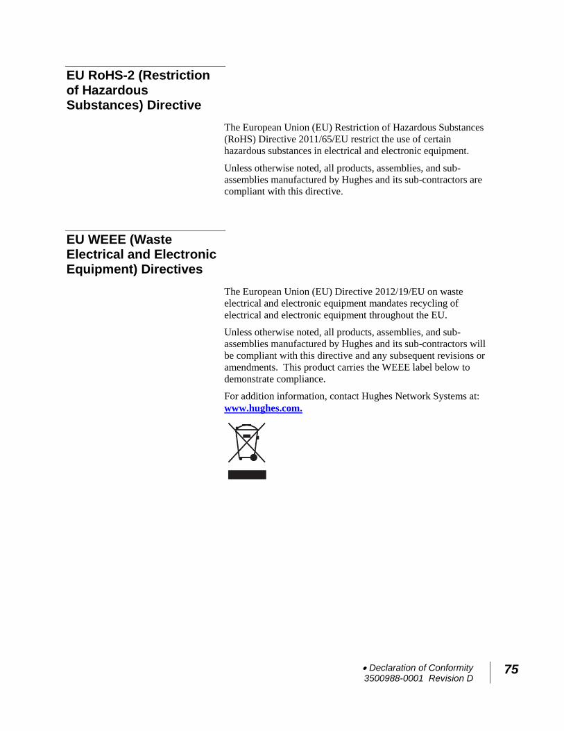
Declaration of Conformity 3500988-0001 Revision D
75
EU RoHS-2 (Restriction of Hazardous Substances) Directive
The European Union (EU) Restriction of Hazardous Substances
(RoHS) Directive 2011/65/EU restrict the use of certain
hazardous substances in electrical and electronic equipment.
Unless otherwise noted, all products, assemblies, and sub-
assemblies manufactured by Hughes and its sub-contractors are
compliant with this directive.
EU WEEE (Waste Electrical and Electronic Equipment) Directives
The European Union (EU) Directive 2012/19/EU on waste
electrical and electronic equipment mandates recycling of
electrical and electronic equipment throughout the EU.
Unless otherwise noted, all products, assemblies, and sub-
assemblies manufactured by Hughes and its sub-contractors will
be compliant with this directive and any subsequent revisions or
amendments. This product carries the WEEE label below to
demonstrate compliance.
For addition information, contact Hughes Network Systems at:
www.hughes.com.
76 Appendices 3500988-0001 Revision D
Glossary APN: An Access Point Name (APN) provides access to an
external network. By default, the SIM Card in your terminal is
configured with the APN of your Service Provider. You may
want to configure further APNs if you have arranged with your
Service Provider to use more than one SIM Card.
BGAN Satellite Terminal: Referenced throughout this
document as the Satellite Terminal, “The Terminal,” or UT.
This device implements and manages BGAN satellite
communications between your computer and Service Provider’s
network.
Quality of Service: Quality of Service (QoS) assigns a level of
priority to certain types of data traffic, in particular high
bandwidth applications such as video and multimedia. QoS
attempts to maintain a guaranteed throughput level, and
minimize error rates and end-to-end latency, by providing a
higher level of service than "best effort" protocols.
DNS Server: The Domain Name System (DNS) is an Internet
service that is required because the Internet does not recognize
the text-based Web address or email address that you type into
your Web browser or email application. All or part of a Web
address or an email address is a domain name, and DNS
translates this domain name into an IP address that is recognized
by the Internet.
A DNS Server holds a database of domain names and IP
addresses, so that when you enter a Web address or email
address, you are directed to the correct IP address over the
Internet.
Ethernet: Ethernet is a local area networking method used
widely throughout the computer industry. It is one of the two
communications interfaces supported by the Satellite Terminal.
Fault Code: A number which uniquely references an error in a
hardware or software system. In the Satellite Terminal, if there
is a fault detected, the fault code and a description are displayed
in suitable windows/screens.
GPS: Global Positioning System. The GPS receiver in the
Satellite Terminal receives signals from the constellation of GPS
satellites. It uses these signals to determine the Terminal’s
location on earth. That location is used during registration to
gain access to the BGAN system.
Appendices 3500988-0001 Revision D
77
HDR: High Data Rate. The HDR streaming options in the 9211
use higher modulation techniques to achieve higher throughput
in the uplink. They are asymmetric services and the downlink is
a regular 64kbps stream. These services are optimized for
applications requiring high speed transmission, such as real-time
video.
IP Address: An Internet Protocol address, or IP address, is a
number that uniquely identifies the computer accessible over a
TCP/IP-based LAN or the Internet that is sending or receiving
information. An IP address is a 32-bit numeric address written
as four numbers, separated by periods and each number is
between 0 and 255. For example, 207.115.79.4 is an IP address.
In the BGAN system, IP addresses for the network and the TE
can be dynamic or static.
Network Dynamic IP Address: A network dynamic IP
address is a temporary address that is assigned by your BGAN
Service Provider when you connect to the BGAN network.
Network Static IP Address: If required, a static IP address
can be assigned by Service Providers to BGAN users when the
SIM is provisioned. This static IP address is used every time
you connect to the BGAN network and is associated with a
specific username and password.
DHCP Address: Local IP address that is assigned by the UT
DHCP server to the TE once connected to the UT. This is a
private IP address that is not routable within the Internet.
Terminal Local IP Address: IP address of the UT to access
the Web UI and talk to the UT via LaunchPad. This address is
configurable by the user. The default local IP address of the
terminal is 192.168.128.100.
Standard Connection: A standard connection is charged by
volume of data sent. The bandwidth you are allocated depends
on terminal type and network availability, but is always ‘best
effort’, that is, you are allocated bandwidth depending on your
requirements and the requirements of other users of the BGAN
network, or BGAN Terminal. This connection class is suitable
for most data types, other than multimedia.
Streaming: A streaming connection gives you a guaranteed data
rate and is charged by the amount of time the connection is
active. Streams are typically used for multimedia data, such as
video.
TE (Terminal Equipment): Terminal equipment refers to the
piece of equipment that is connected to the BGAN UT (e.g.
laptop, video equipment, phone, etc.).
78 Appendices 3500988-0001 Revision D
Traffic Flow Template: A Traffic Flow Template, also called
an Application Template, is a series of data filters such as QoS
(Quality of Service), PDP Context, and security settings that
allow the Core Network to classify packets received from an
external network into the correct PDP Context. When incoming
data arrives at an access point in the Core Network, a packet
classifier will make a PDP Context selection based on the Traffic
Flow Template, and map the incoming data packets into the PDP
Context with the correct QoS attributes. The use of a Traffic
Flow Template allows multiple PDP Contexts to be associated
with the same PDP address.
UT (User Terminal): The user terminal is the BGAN modem
device, i.e. the Hughes 9211 or 9202M.
SIM Card: Your BGAN Service Provider supplies you with a
Universal Mobile Telecommunications System Subscriber SIM
(SIM) Card.
The SIM card is similar to the SIM Card that is commonly used
in a GSM phone. The card holds a microchip that stores
information and encrypts voice and data transmissions, making it
extremely difficult to listen in on calls. The SIM Card also
stores data that identifies the caller to the BGAN Service
Provider.
Virtual Private Network: A Virtual Private Network (VPN)
enables remote offices or users to gain secure access to their
organization's network over the public telecommunications
network. This provides the benefits of remote access without the
expense of dedicated leased or owned lines. VPNs work by
using tunneling protocols, to encrypt data at the sending end, and
decrypt the data at the receiving end. This "tunnel" cannot be
accessed by data that is not properly encrypted.
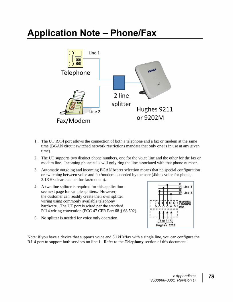
Appendices 3500988-0001 Revision D
79
Application Note – Phone/Fax
1. The UT RJ14 port allows the connection of both a telephone and a fax or modem at the same
time (BGAN circuit switched network restrictions mandate that only one is in use at any given
time).
2. The UT supports two distinct phone numbers, one for the voice line and the other for the fax or
modem line. Incoming phone calls will only ring the line associated with that phone number.
3. Automatic outgoing and incoming BGAN bearer selection means that no special configuration
or switching between voice and fax/modem is needed by the user (4kbps voice for phone,
3.1KHz clear channel for fax/modem).
4. A two line splitter is required for this application –
see next page for sample splitters. However,
the customer can readily create their own splitter
wiring using commonly available telephony
hardware. The UT port is wired per the standard
RJ14 wiring convention (FCC 47 CFR Part 68 § 68.502).
5. No splitter is needed for voice only operation.
Note: if you have a device that supports voice and 3.1kHz/fax with a single line, you can configure the
RJ14 port to support both services on line 1. Refer to the Telephony section of this document.
Hughes 9211 or 9202M
2 line splitter
Telephone
Fax/Modem
Line 1
Line 2
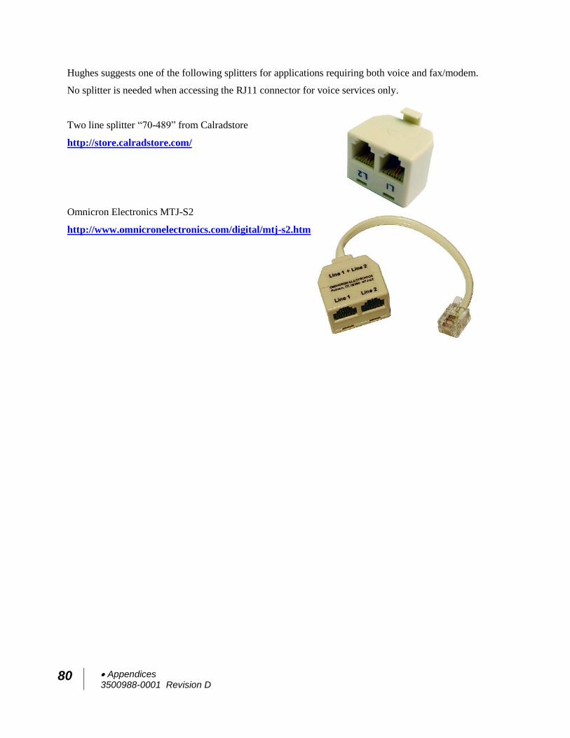
80 Appendices 3500988-0001 Revision D
Hughes suggests one of the following splitters for applications requiring both voice and fax/modem.
No splitter is needed when accessing the RJ11 connector for voice services only.
Two line splitter “70-489” from Calradstore
http://store.calradstore.com/
Omnicron Electronics MTJ-S2
http://www.omnicronelectronics.com/digital/mtj-s2.htm
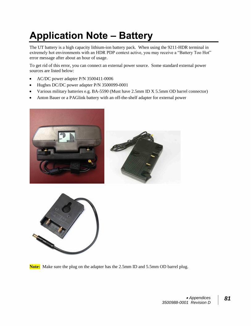
Appendices 3500988-0001 Revision D
81
Application Note – Battery The UT battery is a high capacity lithium-ion battery pack. When using the 9211-HDR terminal in
extremely hot environments with an HDR PDP context active, you may receive a “Battery Too Hot”
error message after about an hour of usage.
To get rid of this error, you can connect an external power source. Some standard external power
sources are listed below:
AC/DC power adapter P/N 3500411-0006
Hughes DC/DC power adapter P/N 3500099-0001
Various military batteries e.g. BA-5590 (Must have 2.5mm ID X 5.5mm OD barrel connector)
Anton Bauer or a PAGlink battery with an off-the-shelf adapter for external power
Note: Make sure the plug on the adapter has the 2.5mm ID and 5.5mm OD barrel plug.
82 Appendices 3500988-0001 Revision D
Application Note – Battery Safety
Safety Information
a. Replace battery with 3500800-0007 or 3500800-0008
battery only. Use of another battery may present a
risk of fire or explosion
b. The battery used in this device may present a risk of
fire or chemical burn if mistreated. Risk of Fire and
Burns. Do Not Open, Crush, Heat Above
(manufacturer’s specified maximum temperature) or
Incinerate. Follow Manufacturer’s Instructions
c. Do not dismantle, open or shred the battery
d. Do not short circuit the battery. Do not store batteries
haphazardly in a box or drawer where they may short
circuit each other or be short circuited by conductive
materials
e. Do not remove a battery from its original packaging
until required for use
f. Do not expose batteries to heat or fire. Avoid storage
in direct sunlight
g. Do not subject the batteries to mechanical shock
h. In the event of a cell leaking, do not allow the liquid
to come into contact with the skin or eyes. If contact
has been made, wash the affected area with copious
amounts of water and seek medical advice
i. Store the batteries in a dry place at a temperature
between 0oC and +40oC
j. Secondary (rechargeable) batteries give their best
performance when they are operated at room
temperature (20oC +/- 5oC)
Charging
a. Only charge batteries with a Hughes 9211 or 9202M
b. The Hughes 9211/9202M charges with a constant-
voltage, constant current battery charger circuit with
the following parameters:
Appendices 3500988-0001 Revision D
83
1. Nominal charge voltages : 8.40 VDC
(Maximum charge voltage: 8.50 VDC)
2. Nominal charge current : 3200 mA
(Maximum charge current: 3250 mA)
3. Charge temperature range: 0oC to +40oC
Disposal
a. Dispose of used battery promptly. Keep away from
children. Do not disassemble and do not dispose of in
fire
b. When disposing of batteries, keep cells or batteries of
different electrochemical systems separate from
each other
c. Recycle or dispose of this battery in accordance with
local regulations. For assistance, refer to
http://www.epa.gov/recycle/how-do-i-recycle-
common-recyclables