Huawei S Series Switch VRPv5 and Cisco Catalyst Switch Huawei S Series Switch VRPv5 and Cisco...
117
Huawei S Series Switch VRPv5 and Cisco Catalyst Switch IOS IOT Report (V1.4) Huawei Technologies CO., LTD. All Rights Reserved
Transcript of Huawei S Series Switch VRPv5 and Cisco Catalyst Switch Huawei S Series Switch VRPv5 and Cisco...

Huawei S Series Switch VRPv5 and Cisco Catalyst
Switch IOS IOT Report (V1.4)
Huawei Technologies CO., LTD.
All Rights Reserved

2015-11-10 Page 2 of 117
Contents
1 Device Version Information ................................................................................................... 3
1.1 Device Version for Interoperability Test ..................................................................................................... 3
1.2 Test Instrument Information ....................................................................................................................... 4
2 Summaries of Test Results and Test Solutions .................................................................... 4
2.1 Summaries of Interoperability Test Results ................................................................................................. 4
2.2 Test Design ................................................................................................................................................ 6
2.2.1 The Design Thoughts ........................................................................................................................ 6
2.2.2 Test Bed Design ................................................................................................................................ 6
2.3 Statement .................................................................................................................................................. 7
2.3.1 Device Type and Version Avaliability ................................................................................................ 7
3 Interoperability Test Report ................................................................................................... 7
3.1 Layer 2 Function ....................................................................................................................................... 7
3.1.1 Interface ........................................................................................................................................... 7
3.1.2 VLAN .............................................................................................................................................13
3.1.3 MUX VLAN ...................................................................................................................................15
3.1.4 LLDP ..............................................................................................................................................20
3.2 Layer 2 Reliability ....................................................................................................................................21
3.2.1 Layer 2 Ring Network Protocol ........................................................................................................21
3.2.2 Eth-OAM Interoperability Test .........................................................................................................52
3.2.3 Link Aggregation Function Interoperability Test ...............................................................................57
3.3 Layer 3 Function ......................................................................................................................................63
3.3.1 IP Routing Interoperability Test ........................................................................................................63
3.3.2 NTP Function ..................................................................................................................................78
3.3.3 MPLS VPN Interoperability Test ......................................................................................................86
3.3.4 Layer 3 Reliability Interoperability Test ......................................................................................... 103
2015-11-10 Page 3 of 117
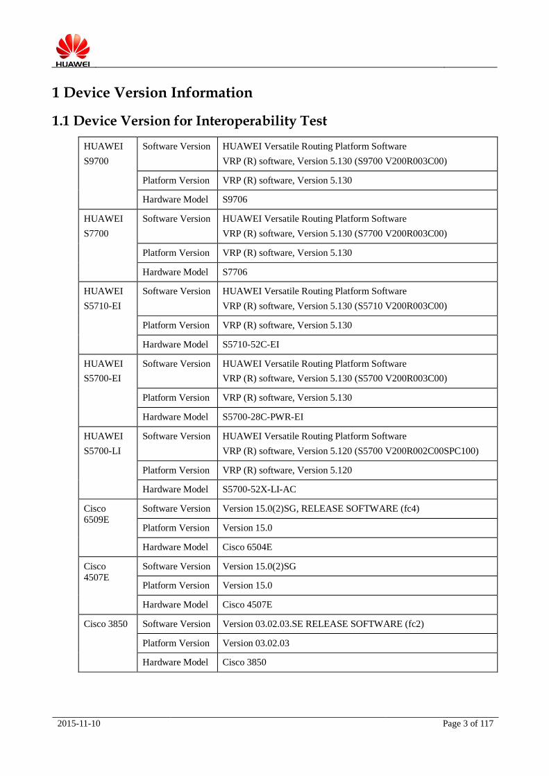
1 Device Version Information
1.1 Device Version for Interoperability Test
HUAWEI
S9700
Software Version HUAWEI Versatile Routing Platform Software
VRP (R) software, Version 5.130 (S9700 V200R003C00)
Platform Version VRP (R) software, Version 5.130
Hardware Model S9706
HUAWEI
S7700
Software Version HUAWEI Versatile Routing Platform Software
VRP (R) software, Version 5.130 (S7700 V200R003C00)
Platform Version VRP (R) software, Version 5.130
Hardware Model S7706
HUAWEI
S5710-EI
Software Version HUAWEI Versatile Routing Platform Software
VRP (R) software, Version 5.130 (S5710 V200R003C00)
Platform Version VRP (R) software, Version 5.130
Hardware Model S5710-52C-EI
HUAWEI
S5700-EI
Software Version HUAWEI Versatile Routing Platform Software
VRP (R) software, Version 5.130 (S5700 V200R003C00)
Platform Version VRP (R) software, Version 5.130
Hardware Model S5700-28C-PWR-EI
HUAWEI
S5700-LI
Software Version HUAWEI Versatile Routing Platform Software
VRP (R) software, Version 5.120 (S5700 V200R002C00SPC100)
Platform Version VRP (R) software, Version 5.120
Hardware Model S5700-52X-LI-AC
Cisco
6509E
Software Version Version 15.0(2)SG, RELEASE SOFTWARE (fc4)
Platform Version Version 15.0
Hardware Model Cisco 6504E
Cisco
4507E
Software Version Version 15.0(2)SG
Platform Version Version 15.0
Hardware Model Cisco 4507E
Cisco 3850 Software Version Version 03.02.03.SE RELEASE SOFTWARE (fc2)
Platform Version Version 03.02.03
Hardware Model Cisco 3850
2015-11-10 Page 4 of 117
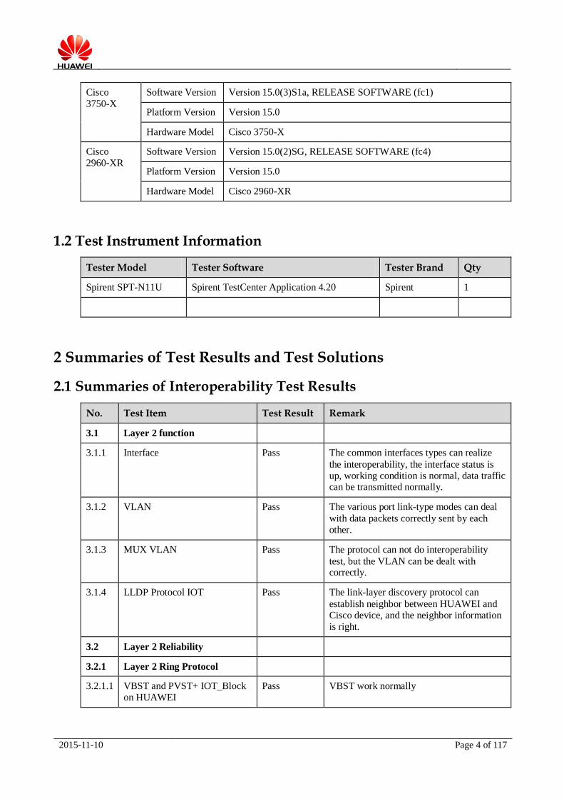
Cisco
3750-X
Software Version Version 15.0(3)S1a, RELEASE SOFTWARE (fc1)
Platform Version Version 15.0
Hardware Model Cisco 3750-X
Cisco
2960-XR
Software Version Version 15.0(2)SG, RELEASE SOFTWARE (fc4)
Platform Version Version 15.0
Hardware Model Cisco 2960-XR
1.2 Test Instrument Information
Tester Model Tester Software Tester Brand Qty
Spirent SPT-N11U Spirent TestCenter Application 4.20 Spirent 1
2 Summaries of Test Results and Test Solutions
2.1 Summaries of Interoperability Test Results
No. Test Item Test Result Remark
3.1 Layer 2 function
3.1.1 Interface Pass The common interfaces types can realize
the interoperability, the interface status is
up, working condition is normal, data traffic can be transmitted normally.
3.1.2 VLAN Pass The various port link-type modes can deal
with data packets correctly sent by each
other.
3.1.3 MUX VLAN Pass The protocol can not do interoperability
test, but the VLAN can be dealt with correctly.
3.1.4 LLDP Protocol IOT Pass The link-layer discovery protocol can
establish neighbor between HUAWEI and
Cisco device, and the neighbor information
is right.
3.2 Layer 2 Reliability
3.2.1 Layer 2 Ring Protocol
3.2.1.1 VBST and PVST+ IOT_Block
on HUAWEI
Pass VBST work normally
2015-11-10 Page 5 of 117
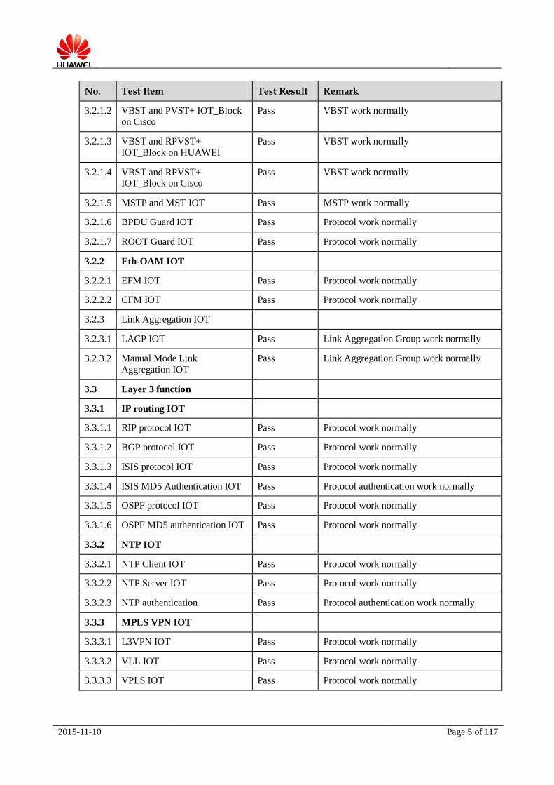
No. Test Item Test Result Remark
3.2.1.2 VBST and PVST+ IOT_Block
on Cisco
Pass VBST work normally
3.2.1.3 VBST and RPVST+
IOT_Block on HUAWEI
Pass VBST work normally
3.2.1.4 VBST and RPVST+ IOT_Block on Cisco
Pass VBST work normally
3.2.1.5 MSTP and MST IOT Pass MSTP work normally
3.2.1.6 BPDU Guard IOT Pass Protocol work normally
3.2.1.7 ROOT Guard IOT Pass Protocol work normally
3.2.2 Eth-OAM IOT
3.2.2.1 EFM IOT Pass Protocol work normally
3.2.2.2 CFM IOT Pass Protocol work normally
3.2.3 Link Aggregation IOT
3.2.3.1 LACP IOT Pass Link Aggregation Group work normally
3.2.3.2 Manual Mode Link
Aggregation IOT
Pass Link Aggregation Group work normally
3.3 Layer 3 function
3.3.1 IP routing IOT
3.3.1.1 RIP protocol IOT Pass Protocol work normally
3.3.1.2 BGP protocol IOT Pass Protocol work normally
3.3.1.3 ISIS protocol IOT Pass Protocol work normally
3.3.1.4 ISIS MD5 Authentication IOT Pass Protocol authentication work normally
3.3.1.5 OSPF protocol IOT Pass Protocol work normally
3.3.1.6 OSPF MD5 authentication IOT Pass Protocol work normally
3.3.2 NTP IOT
3.3.2.1 NTP Client IOT Pass Protocol work normally
3.3.2.2 NTP Server IOT Pass Protocol work normally
3.3.2.3 NTP authentication Pass Protocol authentication work normally
3.3.3 MPLS VPN IOT
3.3.3.1 L3VPN IOT Pass Protocol work normally
3.3.3.2 VLL IOT Pass Protocol work normally
3.3.3.3 VPLS IOT Pass Protocol work normally
2015-11-10 Page 6 of 117
No. Test Item Test Result Remark
3.3.4 Layer 3 Reliability
3.3.4.1 BFD for RIP function IOT Pass Protocol work normally
3.3.4.2 BFD for OSPF function IOT Pass Protocol work normally
3.3.4.3 BFD for ISIS function IOT Pass Protocol work normally
3.3.4.4 BFD for BGP function IOT Pass Protocol work normally
3.3.4.5 VRRP IOT Pass Protocol work normally
2.2 Test Design
2.2.1 The Design Thoughts
As for the hardware of DUTs, we select HUAWEI and Cisco current mainstream campus switches,
covering the products applied on core, aggregation, and access layer. As for the software versions of
DUTs, we select the mainstream commercial versions based on the latest platform, that is HUAWEI VRPv5 platform and Cisco Comware v5 platform.
The interoperability test covers Layer 2 functions, Layer 2 reliabilities, Layer 3 functions, Layer 3
reliabilities. The interoperability test cases are the common campus test properties using at least two
devices to realize the interoperability of protocols and data packets processing. The interoperability
test can fully demonstrate that HUAWEI and Cisco switches have good interoperability on dealing
with protocols and have good consistencies on protocols, can provide references for a mixed network
using HUAWEI and Cisco switches simultaneously.
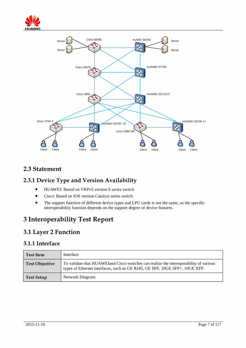
The test bed is designed using three-layer structure. Every layer is interconnected by HUAWEI and
Cisco corresponding switches. The core layer uses High-end chassis switches (HUAWEI S9700/S7700
and Cisco 6509E/4507E) fully interconnected with each other. The aggregation layer uses enhanced
fixed-port switches (HUAWEI S5710-EI and Cisco 3850) interconnected with each other. The access
layer uses Layer 3 access switches (HUAWEI S5700-EI and Cisco 3750-X) and Layer 2 access switches (HUAWEI S5700-LI and Cisco 2960-XR).
The interoperability test cases of this report are based on the following test bed and excerpt
corresponding topologies to represent the test.
2.2.2 Test Bed Design
Layer 3 high reliability symmetrical structure interoperability test bed:
2015-11-10 Page 7 of 117
Cisco 6509E
HUAWEI S5700-LI
HUAWEI S5710 EI
HUAWEI S7700
HUWEI S9700
Cisco 2960-XR
Cisco 3850
Cisco 4507E
HUAWEI S5700 -EICisco 3750-X
Server
Server
Server
Server
Client ClientClientClient Client ClientClientClient
2.3 Statement
2.3.1 Device Type and Version Availability
HUAWEI: Based on VRPv5 version S series switch
Cisco: Based on IOS version Catalyst series switch
The support function of different device types and LPU cards is not the same, so the specific interoperability function depends on the support degree of device features.
3 Interoperability Test Report
3.1 Layer 2 Function
3.1.1 Interface
Test Item Interface
Test Objective To validate that HUAWEIand Cisco switches can realize the interoperability of various
types of Ethernet interfaces, such as GE RJ45, GE SFP, 10GE SFP+, 10GE XFP.
Test Setup Network Diagram:

2015-11-10 Page 8 of 117
Port_1
Port_2 Port_2
Port_1
Tport_1 Tport_2
HW-1Cisco-1
Tester
Pre-conditions:
1. All device work normally;
2. Establish the test environment according to the above diagram.
Test Procedure 1. Connect HUAWEI and Cisco switches with cable. Create VLAN and add interfaces to
the same VLAN;
2. Tester send layer 2 traffic from Tport_1 to Tport_2;
3. Change the types of Ethernet interfaces to be GE RJ45, GE SFP, 10GE SFP+, 10GE XFP and obtain the expected result 1.
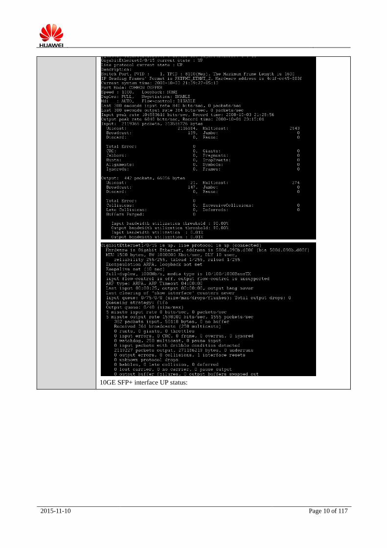
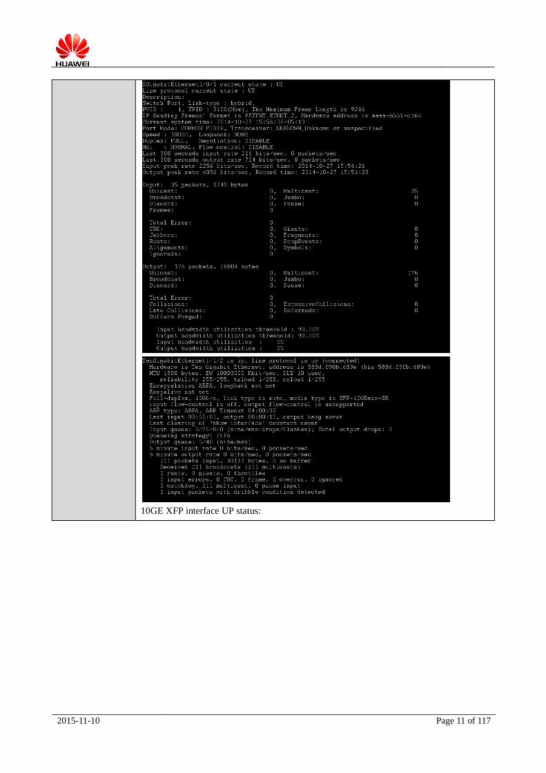
Expected Result The interface negotiation status is normal, the traffic can be received by Tport_2
successfully and there is no packet loss.
Actual Result The interface negotiation status is normal, the traffic can be received by Tport_2
successfully and there is no packet loss.
GE SFP UP status:

2015-11-10 Page 9 of 117
GE RJ45 interface UP status:
2015-11-10 Page 10 of 117
10GE SFP+ interface UP status:
2015-11-10 Page 11 of 117
10GE XFP interface UP status:
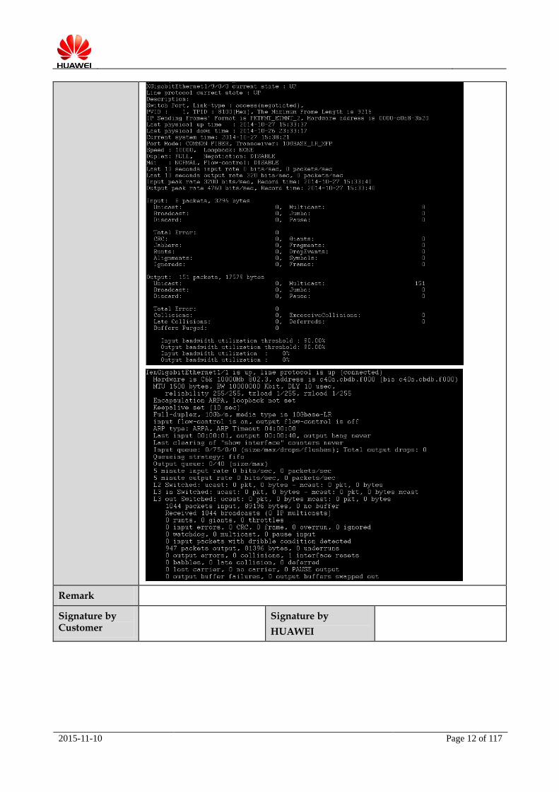
2015-11-10 Page 12 of 117
Remark
Signature by Customer
Signature by
HUAWEI

2015-11-10 Page 13 of 117
3.1.2 VLAN
Test Item VLAN
Test Objective To validate that HUAWEI and Cisco switches support interoperability of VLAN and can
identify each other's VLAN ID
Test Setup Network Diagram:
Port_1
Port_2 Port_2
Port_1
Tport_1 Tport_2
HW-1Cisco-1
Tester
Pre-conditions:
1. All device work normally;
2. Establish the test environment according to the above diagram.
Test Procedure 1. Create VLAN 100 and add interfaces to VLAN 100 in trunk mode on both devices.
Tester sends traffic from Tport_1 to Tport_2, obtain the expected result 1;
2. Change VLAN ID from 100 to 20 on Cisco Switch. Tester sends traffic from Tport_1 to Tport_2, obtain the expected result 2.
Expected Result 1. HUAWEI and Cisco switches support interoperability of same VLAN ID in layer 2.
There is no packet loss;
2. HUAWEI and Cisco switches can not support interoperability of different VLAN IDs in layer 2.
Actual Result 1. HUAWEI and Cisco switches support interoperability of same VLAN ID in layer 2.
There is no packet loss;
2. HUAWEI and Cisco switches can not support interoperability of different VLAN IDs

2015-11-10 Page 14 of 117
in layer 2.
Remark Reference Configuration:
Cisco-1 Configuration:
!
vlan 20, 100
!
interface GigabitEthernet0/1
description Port_1
switchport trunk encapsulation dot1q
switchport trunk allowed vlan 100
switchport mode trunk
!
interface GigabitEthernet0/2
description Port_2
switchport trunk encapsulation dot1q
switchport trunk allowed vlan 100
switchport mode trunk
!
HW-1 Configuration:
#
interface GigabitEthernet0/0/1
port link-type trunk
port trunk allow-pass vlan 100
#
interface GigabitEthernet0/0/2
port link-type trunk
port trunk allow-pass vlan 100
#
Signature by Customer
Signature by HUAWEI

2015-11-10 Page 15 of 117
3.1.3 MUX VLAN
Test Item MUX VLAN
Test Objective To validate HUAWEI and Cisco can support the interoperability of MUX VLAN
Test Setup Network Diagram:
Port_1-
Port_3
Port_4 Port_4
Port_1-
Port_3
Tport_1-
Tport_3
Tport_4-
Tport_6
HW-1Cisco-1
Tester
Pre-conditions:
1. All device work normally;
2. Establish the test environment according to the above diagram.
Tester traffic constructed:
Stream1: SMAC:0001-0001-0001 DMAC:0001-0001-0002 Bandwidth: 1000frame/s
Stream2: SMAC:0001-0001-0003 DMAC:0001-0001-0004 Bandwidth: 1000frame/s
Stream3: SMAC:0001-0001-0005 DMAC:0001-0001-0006 Bandwidth: 1000frame/s
Stream4: SMAC:0001-0001-0007 DMAC:0001-0001-0008 Bandwidth: 1000frame/s
Stream5: SMAC:0001-0001-0009 DMAC:0001-0001-0010 Bandwidth: 1000frame/s
Stream6: SMAC:0001-0001-0011 DMAC:0001-0001-0012 Bandwidth: 1000frame/s
Test Procedure 1. Create VLAN 100,10,20 on both devices and add interfaces to VLANs in trunk mode;
2. Cisco configures Primary VLAN globally, specify Community VLAN and Isolated
VLAN. The three interfaces of Tester connected with device configure to be Primary
VLAN (VLAN100), Community VLAN (VLAN10), Isolated VLAN (VLAN20)
separately;
3. HUAWEI configures MUX VLAN globally, specify Group VLAN and Separate
VLAN. The three interfaces of Tester connected with device configure to be Principal VLAN (VLAN100), Group VLAN (VLAN10), Separate VLAN (VLAN20) separately;
4. Tester Tport_1(Primary VLAN) send Stream1, obtain the expected result 1;
5. Tester Tport_2(Community VLAN) send Stream2, obtain the expected result 2;
6. Tester Tport_3(Isolated VLAN) send Stream3, obtain the expected result 3;
7. Tester Tport_4(Principal VLAN) send Stream4, obtain the expected result 4;
8. Tester Tport_5(Group VLAN) send Stream5, obtain the expected result 5;
9. Tester Tport_6(Separate VLAN) send Stream6, obtain the expected result 6.

2015-11-10 Page 16 of 117
Expected Result 1. The interfaces belong to the Cisco Community VLAN, Isolate VLAN, HUAWEI
Principal VLAN, Group VLAN, and Separate VLAN can receive the stream normally;
2. The interfaces belong to Cisco Primary VLAN, HUAWEI Principal VLAN, and Group VLAN can receive the stream normally;
3. The interfaces belong to Cisco Primary VLAN and HUAWEI Principal VLAN can
receive the stream normally;
4. The interfaces belong to Cisco Primary VLAN, Community VLAN, Isolated VLAN, HUAWEI Group VLAN, and Separate VLAN can receive the stream normally;
5. The interfaces belong to Cisco Primary VLAN, Community VLAN, and HUAWEI Principal VLAN can receive the stream normally;
6. The interfaces belong to Cisco Primary VLAN and HUAWEI Principal VLAN can
receive the stream normally.
Actual Result 1. The interfaces belong to the Cisco Community VLAN, Isolate VLAN, HUAWEI
Principal VLAN, Group VLAN, and Separate VLAN can receive the stream normally;
2. The interfaces belong to Cisco Primary VLAN, HUAWEI Principal VLAN, and Group VLAN can receive the stream normally;
3. The interfaces belong to Cisco Primary VLAN and HUAWEI Principal VLAN can
receive the stream normally;

2015-11-10 Page 17 of 117
4. The interfaces belong to Cisco Primary VLAN, Community VLAN, Isolated VLAN, HUAWEI Group VLAN, and Separate VLAN can receive the stream normally;
5. The interfaces belong to Cisco Primary VLAN, Community VLAN, and HUAWEI Principal VLAN can receive the stream normally;
6. The interfaces belong to Cisco Primary VLAN and HUAWEI Principal VLAN can receive the stream normally.

2015-11-10 Page 18 of 117
Remark Reference Configuration:
Cisco-1 Configuration:
!
vlan 100 #configure Primary VLAN function
private-vlan primary
private-vlan association 10,20
end
!
interface FastEthernet0/4
description Port_4
switchport trunk encapsulation dot1q
switchport trunk allowed vlan 10,20,100
switchport mode trunk
end
!
interface FastEthernet0/6 #define PVLAN Promiscuous interface, binding PVLAN
mapping relations
description Port_1
switchport private-vlan mapping 100 10,20
switchport mode private-vlan promiscuous
end
!
interface FastEthernet0/7 #define PVLAN host interface, binding PVLAN and
Community VLAN
description Port_2
switchport private-vlan host-association 100 10
switchport mode private-vlan host
end
!
interface FastEthernet0/8 #define PVLAN host interface, binding PVLAN and
Isolated VLAN

2015-11-10 Page 19 of 117
description Port_3
switchport private-vlan host-association 100 20
switchport mode private-vlan host
end
HW-1 Configuration:
#
vlan 100 #configure MUX VLAN function
mux-vlan
subordinate separate 20
subordinate group 10
#
#
interface GigabitEthernet0/0/4
description Port_4
port link-type trunk
port trunk allow-pass vlan 10 20 100
#
#
interface GigabitEthernet0/0/5 #configure interface to add Principal VLAN, enable
MUX VLAN function
description Port_1
port link-type hybrid
port hybrid pvid vlan 100
port hybrid untagged vlan 100
port mux-vlan enable vlan 100
#
#
interface GigabitEthernet0/0/7 #configure interface to add Group VLAN, enable MUX
VLAN function
description Port_2
port link-type hybrid
port hybrid pvid vlan 10
port hybrid untagged vlan 10
port mux-vlan enable vlan 10
#
#
interface GigabitEthernet0/0/8 #configure interface to add Separate VLAN, enable
MUX VLAN function
description Port_3
port link-type hybrid
port hybrid pvid vlan 20
port hybrid untagged vlan 20
2015-11-10 Page 20 of 117
port mux-vlan enable vlan 20
#
Signature by Customer
Signature by HUAWEI
3.1.4 LLDP
Test Item LLDP Function Interoperability Test
Test Objective To validate that HUAWEI and Cisco switches can realize the interoperability test of
LLDP function.
Test Setup Network Diagram:
Pre-conditions:
1. All device work normally;
2. Establish the test environment according to the above diagram.
Test Procedure 1. Enable LLDP function on both device;
2. Check LLDP neighbor information on both devices, obtain the expected result 1.
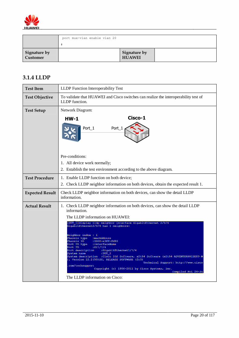
Expected Result Check LLDP neighbor information on both devices, can show the detail LLDP
information.
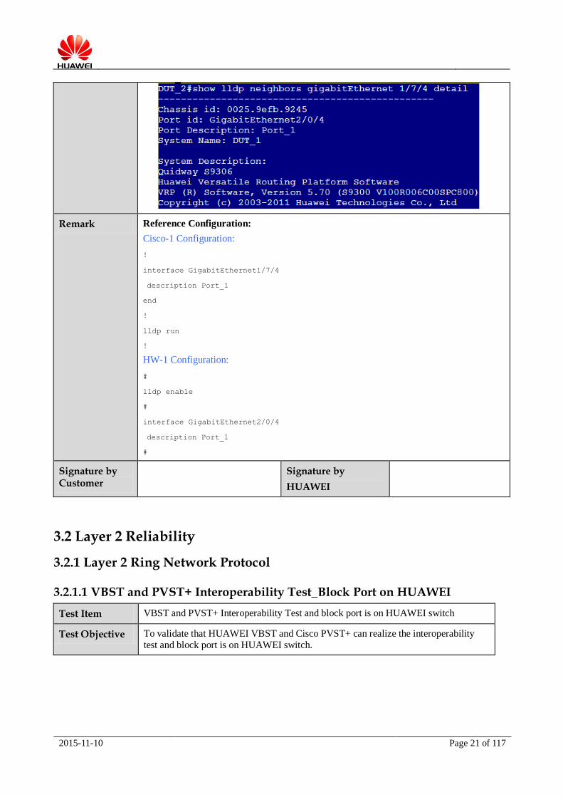
Actual Result 1. Check LLDP neighbor information on both devices, can show the detail LLDP
information.
The LLDP information on HUAWEI:
The LLDP information on Cisco:
HW-1 Cisco-1
Port_1 Port_1
2015-11-10 Page 21 of 117
Remark Reference Configuration:
Cisco-1 Configuration:
!
interface GigabitEthernet1/7/4
description Port_1
end
!
lldp run
!
HW-1 Configuration:
#
lldp enable
#
interface GigabitEthernet2/0/4
description Port_1
#
Signature by Customer
Signature by
HUAWEI
3.2 Layer 2 Reliability
3.2.1 Layer 2 Ring Network Protocol
3.2.1.1 VBST and PVST+ Interoperability Test_Block Port on HUAWEI
Test Item VBST and PVST+ Interoperability Test and block port is on HUAWEI switch
Test Objective To validate that HUAWEI VBST and Cisco PVST+ can realize the interoperability
test and block port is on HUAWEI switch.

2015-11-10 Page 22 of 117
Test Setup Network Diagram:
Port_1 Port_2
HW-1
Tport_1 Tport_2
Tester
Port_1Port_2
Cisco-1
Port_3Port_3
Port_1 Port_2
HW-2
Pre-conditions:
1. All device work normally;
2. Establish the test environment according to the above diagram.
Test Procedure 1. Configure stp mode to be PVST+ on Cisco-1, configure Cisco-1 to be root bridge
of VLAN 1, 100;
2. Configure stp mode to be VBST on HW-1 and HW-2, the path cost method to be dot1d-1998 on both devices, configure HW-1 to be secondary root bridge;
3. Check stp status on Cisco and HUAWEI, obtain the expected result 1.
Expected Result Cisco-1 is root bridge of VLAN 1 and VLAN 100, the block port is Port_1 on HW-2.
Actual Result Cisco-1 is root bridge of VLAN 1 and VLAN 100, the block port is Port_1 on HW-2.
Cisco-1 is root bridge of VLAN 1 and VLAN 100:

2015-11-10 Page 23 of 117
HW-1 VBST consider Cisco-1 as root bridge:
HW-2 VBST consider Cisco -1 as root bridge, according to the configuration, Port_1 on HW-2 is the block port of VLAN 1 and VLAN 100:
Shutdown HW- 1 Port_2, observe the convergence time of VLAN 1 and VLAN 100:
VLAN 1 convergence time: 298630/10000=29.8s
VLAN 100 convergence time: 299564/10000=29.9s
2015-11-10 Page 24 of 117
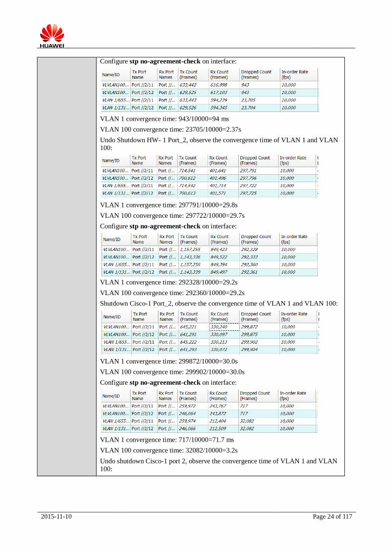
Configure stp no-agreement-check on interface:
VLAN 1 convergence time: 943/10000=94 ms
VLAN 100 convergence time: 23705/10000=2.37s
Undo Shutdown HW- 1 Port_2, observe the convergence time of VLAN 1 and VLAN
100:
VLAN 1 convergence time: 297791/10000=29.8s
VLAN 100 convergence time: 297722/10000=29.7s
Configure stp no-agreement-check on interface:
VLAN 1 convergence time: 292328/10000=29.2s
VLAN 100 convergence time: 292360/10000=29.2s
Shutdown Cisco-1 Port_2, observe the convergence time of VLAN 1 and VLAN 100:
VLAN 1 convergence time: 299872/10000=30.0s
VLAN 100 convergence time: 299902/10000=30.0s
Configure stp no-agreement-check on interface:
VLAN 1 convergence time: 717/10000=71.7 ms
VLAN 100 convergence time: 32082/10000=3.2s
Undo shutdown Cisco-1 port 2, observe the convergence time of VLAN 1 and VLAN
100:

2015-11-10 Page 25 of 117
VLAN 1 convergence time: 296378/10000=29.6s
VLAN 100 convergence time: 296382/10000=29.6s
Configure stp no-agreement-check on interface:
VLAN 1 convergence time: 294177/10000=29.4s
VLAN 100convergence time: 294178/10000=29.4s
Remark Reference Configuration:
Cisco-1 Configuration:
!
spanning-tree mode pvst
spanning-tree extend system-id
no spanning-tree vlan 129-200, 300, 400, 600
spanning-tree vlan 1, 100 priority 0
!
!
interface GigabitEthernet0/2
description Port_2
switchport trunk encapsulation dot1q
switchport trunk allowed vlan 1, 100
switchport mode trunk
!
interface GigabitEthernet0/3
description Port_3
switchport trunk encapsulation dot1q
switchport trunk allowed vlan 1, 100
switchport mode trunk
!
!
interface GigabitEthernet1/1
description Port_1
switchport trunk encapsulation dot1q
switchport trunk allowed vlan 1, 100
switchport mode trunk

2015-11-10 Page 26 of 117
spanning-tree portfast trunk
!
HW-1 Configuration:
#
stp mode vbst
stp pathcost-standard dot1d-1998
stp vlan 1 100 priority 4096
#
#
interface GigabitEthernet2/0/1
description Port_2
port link-type trunk
port trunk allow-pass vlan 100
stp no-agreement-check
#
interface GigabitEthernet2/0/3
description Port_3
port link-type trunk
port trunk allow-pass vlan 100
#
interface GigabitEthernet2/0/4
description Port_1
port link-type trunk
port trunk allow-pass vlan 100
stp edged-port enable
#
HW-2 Configuration:
#
stp mode vbst
stp pathcost-standard dot1d-1998
#
interface GigabitEthernet0/0/1
description Port_2
port link-type trunk
port trunk allow-pass vlan 100
stp no-agreement-check
#
interface GigabitEthernet0/0/2
description Port_1
port link-type trunk
port trunk allow-pass vlan 100
2015-11-10 Page 27 of 117
#
Signature by Customer
Signature by HUAWEI
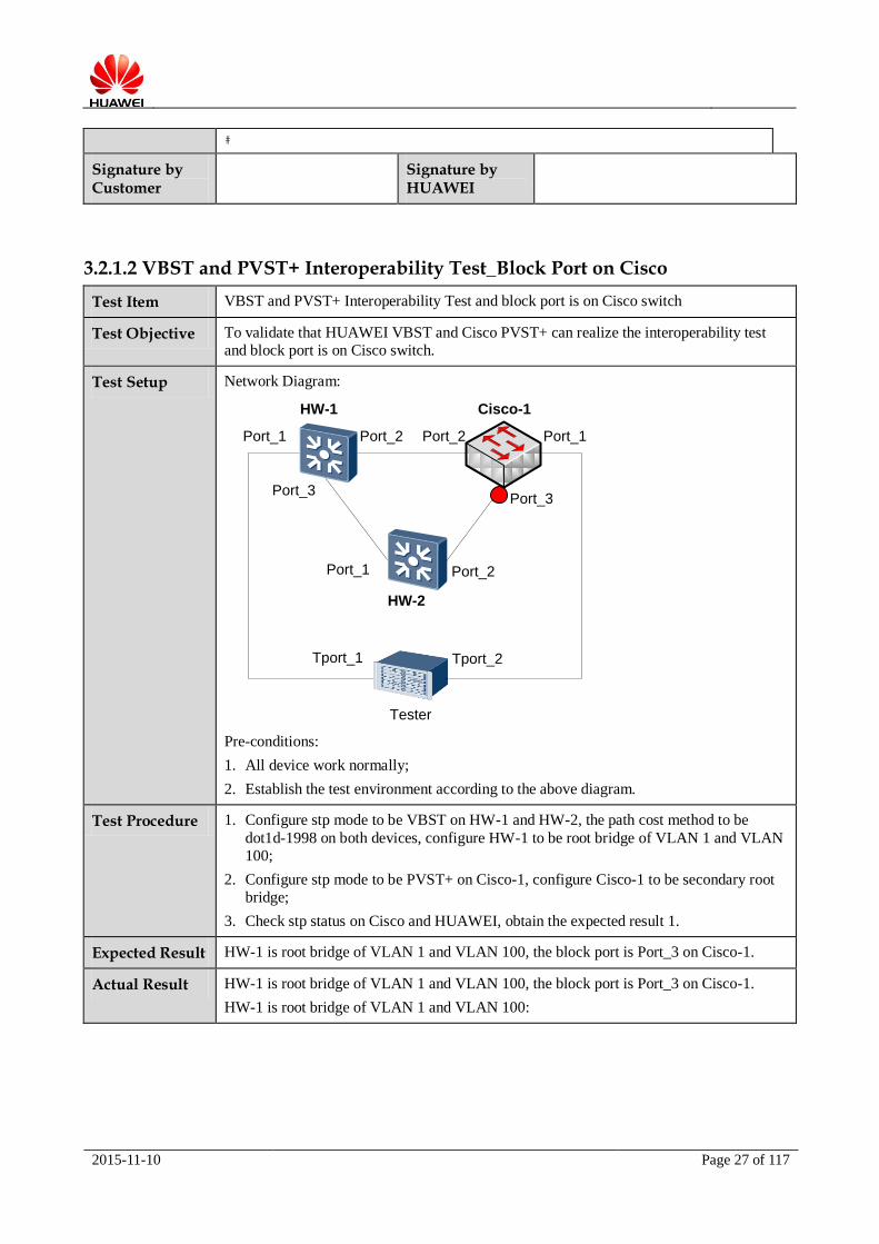
3.2.1.2 VBST and PVST+ Interoperability Test_Block Port on Cisco
Test Item VBST and PVST+ Interoperability Test and block port is on Cisco switch
Test Objective To validate that HUAWEI VBST and Cisco PVST+ can realize the interoperability test
and block port is on Cisco switch.
Test Setup Network Diagram:
Port_1 Port_2
HW-1
Tport_1 Tport_2
Tester
Port_1Port_2
Cisco-1
Port_3Port_3
Port_1 Port_2
HW-2
Pre-conditions:
1. All device work normally;
2. Establish the test environment according to the above diagram.
Test Procedure 1. Configure stp mode to be VBST on HW-1 and HW-2, the path cost method to be
dot1d-1998 on both devices, configure HW-1 to be root bridge of VLAN 1 and VLAN
100;
2. Configure stp mode to be PVST+ on Cisco-1, configure Cisco-1 to be secondary root
bridge;
3. Check stp status on Cisco and HUAWEI, obtain the expected result 1.
Expected Result HW-1 is root bridge of VLAN 1 and VLAN 100, the block port is Port_3 on Cisco-1.
Actual Result HW-1 is root bridge of VLAN 1 and VLAN 100, the block port is Port_3 on Cisco-1.
HW-1 is root bridge of VLAN 1 and VLAN 100:

2015-11-10 Page 28 of 117
HW-2 VBST consider HW-1 as root bridge:
Cisco-1 PVST+ consider HW-1 as root bridge, according to the configuration, Port_3 on
Cisco-1 is the block port of VLAN 1 and VLAN 100:
Shutdown HW- 1 Port_2, observe the convergence time of VLAN 1 and VLAN 100:
VLAN 1 convergence time: 293904/10000=29.4s
VLAN 100 convergence time: 304912/10000=30.5s
2015-11-10 Page 29 of 117
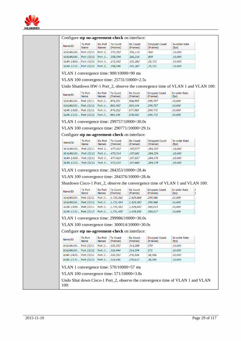
Configure stp no-agreement-check on interface:
VLAN 1 convergence time: 900/10000=90 ms
VLAN 100 convergence time: 25731/10000=2.5s
Undo Shutdown HW-1 Port_2, observe the convergence time of VLAN 1 and VLAN 100:
VLAN 1 convergence time: 299757/10000=30.0s
VLAN 100 convergence time: 290771/10000=29.1s
Configure stp no-agreement-check on interface:
VLAN 1 convergence time: 284353/10000=28.4s
VLAN 100 convergence time: 284376/10000=28.4s
Shutdown Cisco-1 Port_2, observe the convergence time of VLAN 1 and VLAN 100:
VLAN 1 convergence time: 299986/10000=30.0s
VLAN 100 convergence time: 300014/10000=30.0s
Configure stp no-agreement-check on interface:
VLAN 1 convergence time: 570/10000=57 ms
VLAN 100 convergence time: 571/10000=3.8s
Undo Shut down Cisco-1 Port_2, observe the convergence time of VLAN 1 and VLAN
100:

2015-11-10 Page 30 of 117
VLAN 1 convergence time: 297904/10000=29.8s
VLAN 100 convergence time: 297933/10000=29.8s
Configure stp no-agreement-check on interface:
VLAN 1 convergence time: 298630/10000=29.8s
VLAN 100 convergence time: 299564/10000=29.9s
Remark Reference Configuration:
Cisco-1 Configuration:
!
spanning-tree mode pvst
spanning-tree extend system-id
no spanning-tree vlan 129-200, 300, 400, 600
spanning-tree vlan 1, 100 priority 61440
!
!
interface GigabitEthernet0/2
description Port_2
switchport trunk encapsulation dot1q
switchport trunk allowed vlan 1, 100
switchport mode trunk
!
interface GigabitEthernet0/3
description Port_3
switchport trunk encapsulation dot1q
switchport trunk allowed vlan 1, 100
switchport mode trunk
!
!
interface GigabitEthernet1/1
description Port_1
switchport trunk encapsulation dot1q
switchport trunk allowed vlan 1, 100
switchport mode trunk

2015-11-10 Page 31 of 117
spanning-tree portfast trunk
!
HW-1 Configuration:
#
stp mode vbst
stp pathcost-standard dot1d-1998
stp vlan 1 100 priority 4096
#
#
interface GigabitEthernet2/0/1
description Port_2
port link-type trunk
port trunk allow-pass vlan 100
stp no-agreement-check
#
interface GigabitEthernet2/0/3
description Port_3
port link-type trunk
port trunk allow-pass vlan 100
#
interface GigabitEthernet2/0/4
description Port_1
port link-type trunk
port trunk allow-pass vlan 100
stp edged-port enable
#
HW-2 Configuration:
#
stp mode vbst
stp pathcost-standard dot1d-1998
#
interface GigabitEthernet0/0/1
description Port_2
port link-type trunk
port trunk allow-pass vlan 100
stp no-agreement-check
#
interface GigabitEthernet0/0/2
description Port_1
port link-type trunk
port trunk allow-pass vlan 100
2015-11-10 Page 32 of 117
#
Signature by Customer
Signature by HUAWEI
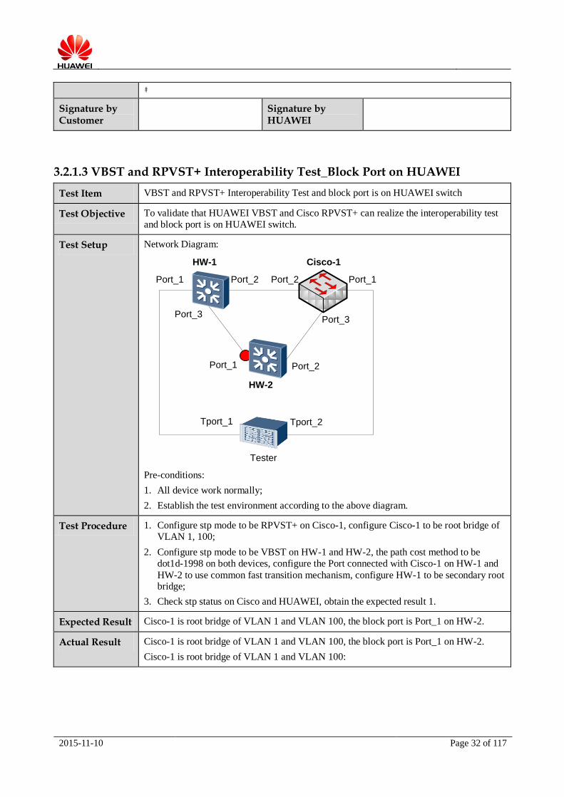
3.2.1.3 VBST and RPVST+ Interoperability Test_Block Port on HUAWEI
Test Item VBST and RPVST+ Interoperability Test and block port is on HUAWEI switch
Test Objective To validate that HUAWEI VBST and Cisco RPVST+ can realize the interoperability test
and block port is on HUAWEI switch.
Test Setup Network Diagram:
Port_1 Port_2
HW-1
Tport_1 Tport_2
Tester
Port_1Port_2
Cisco-1
Port_3Port_3
Port_1 Port_2
HW-2
Pre-conditions:
1. All device work normally;
2. Establish the test environment according to the above diagram.
Test Procedure 1. Configure stp mode to be RPVST+ on Cisco-1, configure Cisco-1 to be root bridge of
VLAN 1, 100;
2. Configure stp mode to be VBST on HW-1 and HW-2, the path cost method to be
dot1d-1998 on both devices, configure the Port connected with Cisco-1 on HW-1 and
HW-2 to use common fast transition mechanism, configure HW-1 to be secondary root bridge;
3. Check stp status on Cisco and HUAWEI, obtain the expected result 1.
Expected Result Cisco-1 is root bridge of VLAN 1 and VLAN 100, the block port is Port_1 on HW-2.
Actual Result Cisco-1 is root bridge of VLAN 1 and VLAN 100, the block port is Port_1 on HW-2.
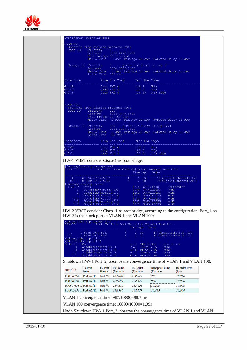
Cisco-1 is root bridge of VLAN 1 and VLAN 100:
2015-11-10 Page 33 of 117
HW-1 VBST consider Cisco-1 as root bridge:
HW-2 VBST consider Cisco -1 as root bridge, according to the configuration, Port_1 on HW-2 is the block port of VLAN 1 and VLAN 100:
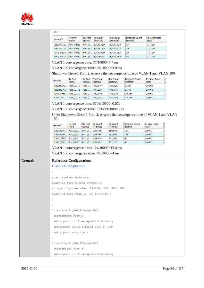
Shutdown HW- 1 Port_2, observe the convergence time of VLAN 1 and VLAN 100:
VLAN 1 convergence time: 987/10000=98.7 ms
VLAN 100 convergence time: 10890/10000=1.09s
Undo Shutdown HW- 1 Port_2, observe the convergence time of VLAN 1 and VLAN
2015-11-10 Page 34 of 117
100:
VLAN 1 convergence time: 77/10000=7.7 ms
VLAN 100 convergence time: 39/10000=3.9 ms
Shutdown Cisco-1 Port_2, observe the convergence time of VLAN 1 and VLAN 100:
VLAN 1 convergence time: 5706/10000=0.57s
VLAN 100 convergence time: 32359/10000=3.2s
Undo Shutdown Cisco-1 Port_2, observe the convergence time of VLAN 1 and VLAN
100:
VLAN 1 convergence time: 124/10000=12.4 ms
VLAN 100 convergence time: 40/10000=4 ms
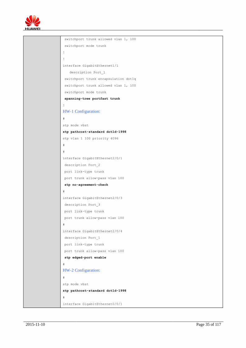
Remark Reference Configuration:
Cisco-1 Configuration:
!
spanning-tree mode pvst
spanning-tree extend system-id
no spanning-tree vlan 129-200, 300, 400, 600
spanning-tree vlan 1, 100 priority 0
!
!
interface GigabitEthernet0/2
description Port_2
switchport trunk encapsulation dot1q
switchport trunk allowed vlan 1, 100
switchport mode trunk
!
interface GigabitEthernet0/3
description Port_3
switchport trunk encapsulation dot1q
2015-11-10 Page 35 of 117
switchport trunk allowed vlan 1, 100
switchport mode trunk
!
!
interface GigabitEthernet1/1
description Port_1
switchport trunk encapsulation dot1q
switchport trunk allowed vlan 1, 100
switchport mode trunk
spanning-tree portfast trunk
!
HW-1 Configuration:
#
stp mode vbst
stp pathcost-standard dot1d-1998
stp vlan 1 100 priority 4096
#
#
interface GigabitEthernet2/0/1
description Port_2
port link-type trunk
port trunk allow-pass vlan 100
stp no-agreement-check
#
interface GigabitEthernet2/0/3
description Port_3
port link-type trunk
port trunk allow-pass vlan 100
#
interface GigabitEthernet2/0/4
description Port_1
port link-type trunk
port trunk allow-pass vlan 100
stp edged-port enable
#
HW-2 Configuration:
#
stp mode vbst
stp pathcost-standard dot1d-1998
#
interface GigabitEthernet0/0/1

2015-11-10 Page 36 of 117
description Port_2
port link-type trunk
port trunk allow-pass vlan 100
stp no-agreement-check
#
interface GigabitEthernet0/0/2
description Port_1
port link-type trunk
port trunk allow-pass vlan 100
#
Signature by Customer
Signature by HUAWEI
3.2.1.4 VBST and RPVST+ Interoperability Test_Block Port on Cisco
Test Item VBST and RPVST+ Interoperability Test and block port is on Cisco switch
Test Objective To validate that HUAWEI VBST and Cisco RPVST+ can realize the interoperability test
and block port is on Cisco switch.
Test Setup Network Diagram:
Port_1 Port_2
HW-1
Tport_1 Tport_2
Tester
Port_1Port_2
Cisco-1
Port_3Port_3
Port_1 Port_2
HW-2
Pre-conditions:
1. All device work normally;
2. Establish the test environment according to the above diagram.
Test Procedure 1. Configure stp mode to be VBST on HW-1 and HW-2, the path cost method to be
dot1d-1998 on both devices, configure the Port connected with Cisco-1 on HW-1 and
HW-2 to use common fast transition mechanism, configure HW-1 to be root bridge of VLAN 1 and VLAN 100;

2015-11-10 Page 37 of 117
2. Configure stp mode to be RPVST+ on Cisco-1, configure Cisco-1 to be secondary root bridge;
3. Check stp status on Cisco and HUAWEI, obtain the expected result 1.
Expected Result HW-1 is root bridge of VLAN 1 and VLAN 100, the block port is Port_3 on Cisco-1.
Actual Result HW-1 is root bridge of VLAN 1 and VLAN 100, the block port is Port_3 on Cisco-1.
HW-1 is root bridge of VLAN 1 and VLAN 100:
HW-2 VBST consider HW-1 as root bridge:
Cisco-1 RPVST+ consider HW-1 as root bridge, according to the configuration, Port_3 on Cisco-1 is the block port of VLAN 1 and VLAN 100:
Shutdown HW-1 Port_2, observe the convergence time of VLAN 1 and VLAN 100:

2015-11-10 Page 38 of 117
VLAN 1 convergence time: 8946/10000=0.89s
VLAN 100 convergence time: 8938/10000=0.899s
Undo Shutdown HW-1 Port_2, observe the convergence time of VLAN 1 and VLAN 100:
VLAN 1 convergence time: 97/10000=9.7 ms
VLAN 100 convergence time: 141/10000=14.1 ms
Shutdown Cisco-1 Port_2, observe the convergence time of VLAN 1 and VLAN 100:
VLAN 1 convergence time: 141/10000=14.1 ms
VLAN 100 convergence time: 140/10000=14.0 ms
Undo Shutdown Cisco-1 Port_2, observe the convergence time of VLAN 1 and VLAN 100:
VLAN 1 convergence time: 114/10000=11.4 ms
VLAN 100 convergence time: 124/10000=12.4 ms
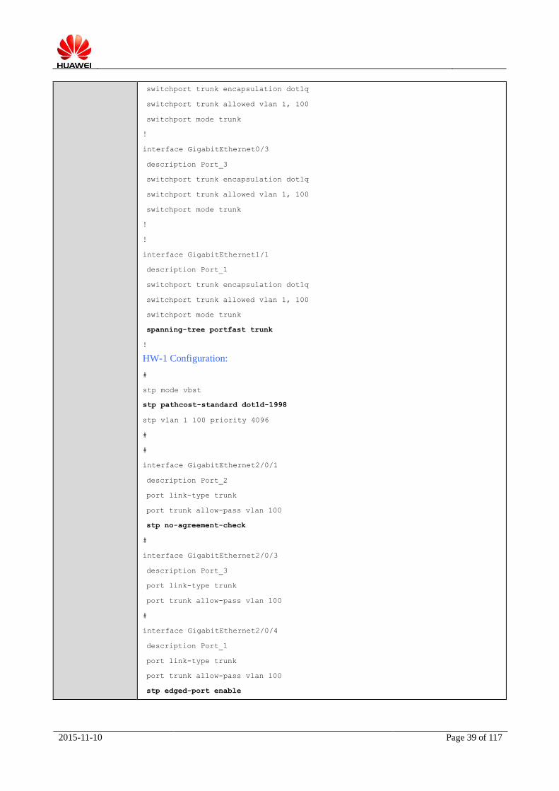
Remark Reference Configuration:
Cisco-1 Configuration:
!
spanning-tree mode pvst
spanning-tree extend system-id
no spanning-tree vlan 129-200, 300, 400, 600
spanning-tree vlan 1, 100 priority 61440
!
!
interface GigabitEthernet0/2
description Port_2
2015-11-10 Page 39 of 117
switchport trunk encapsulation dot1q
switchport trunk allowed vlan 1, 100
switchport mode trunk
!
interface GigabitEthernet0/3
description Port_3
switchport trunk encapsulation dot1q
switchport trunk allowed vlan 1, 100
switchport mode trunk
!
!
interface GigabitEthernet1/1
description Port_1
switchport trunk encapsulation dot1q
switchport trunk allowed vlan 1, 100
switchport mode trunk
spanning-tree portfast trunk
!
HW-1 Configuration:
#
stp mode vbst
stp pathcost-standard dot1d-1998
stp vlan 1 100 priority 4096
#
#
interface GigabitEthernet2/0/1
description Port_2
port link-type trunk
port trunk allow-pass vlan 100
stp no-agreement-check
#
interface GigabitEthernet2/0/3
description Port_3
port link-type trunk
port trunk allow-pass vlan 100
#
interface GigabitEthernet2/0/4
description Port_1
port link-type trunk
port trunk allow-pass vlan 100
stp edged-port enable

2015-11-10 Page 40 of 117
#
HW-2 Configuration:
#
stp mode vbst
stp pathcost-standard dot1d-1998
#
interface GigabitEthernet0/0/1
description Port_2
port link-type trunk
port trunk allow-pass vlan 100
stp no-agreement-check
#
interface GigabitEthernet0/0/2
description Port_1
port link-type trunk
port trunk allow-pass vlan 100
#
Signature by Customer
Signature by HUAWEI
3.2.1.5 MSTP and MST Interoperability Test
Test Item MSTP and MST Interoperability Test
Test Objective To validate that HUAWEI MSTP and Cisco MST can realize the interoperability test.
Test Setup Network Diagram:
Port_1
Tport_1
HW-1 Cisco-1
Tester
HW-2
Port_2 Port_2
Port_3 Port_3
Port_1 Port_2
Port_1
Tport_2

2015-11-10 Page 41 of 117
Pre-conditions:
1. All device work normally;
2. Establish the test environment according to the above diagram.
Test Procedure 1. Configure stp mode to be MST on Cisco-1, add all ports to VLAN 10 and VLAN 20 in
trunk mode, map VLAN 10 to MST0, map VLAN 20 to MST1, configure Cisco-1 to be root bridge of MST0;
2. Configure stp mode to be MSTP on HW-1 and HW-2, add all ports to VLAN 10 and
VLAN 20 in trunk mode, map VLAN 10 to MST0, map VLAN 20 to MST1, configure
HW-1 to be root bridge of MST1, configure the path cost method to be dot1d-1998 on
both devices, configure the Port connected with Cisco-1 on HW-1 and HW-2 to use
common fast transition mechanism;
3. Check stp status on Cisco-1, obtain the expected result 1;
4. Check stp status on HW-1, obtain the expected result 2.
Expected Result 1. Cisco-1 is the root bridge of MST0, HW-1 is the root bridge of MST1, the block port
of MST1 is Port_3 on Cisco-1;
2. HW-1 is the root bridge of MST1, Cisco-1 is the root bridge of MST0, the block port of MST0 is Port_3 on HW-1.
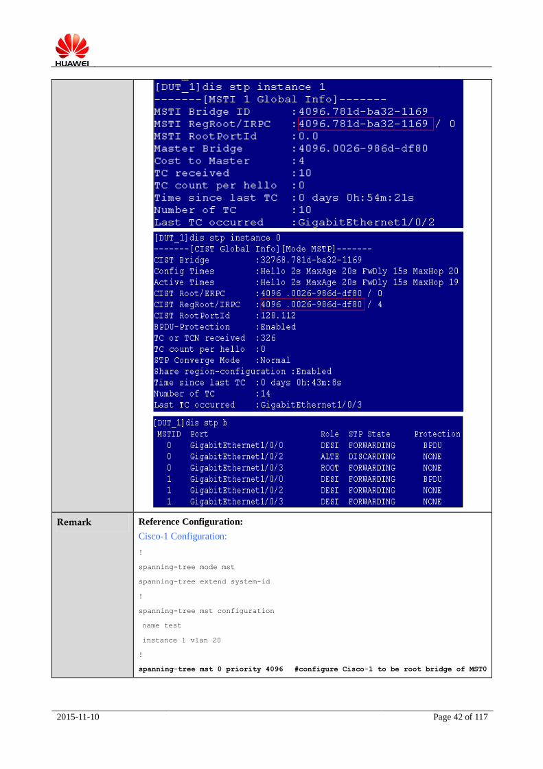
Actual Result 1. Cisco-1 is the root bridge of MST0, HW-1 is the root bridge of MST1, the block port
of MST1 is Port_3 on Cisco-1;
2. HW-1 is the root bridge of MST1, Cisco-1 is the root bridge of MST0, the block port of MST0 is Port_3 on HW-1.
2015-11-10 Page 42 of 117
Remark Reference Configuration:
Cisco-1 Configuration:
!
spanning-tree mode mst
spanning-tree extend system-id
!
spanning-tree mst configuration
name test
instance 1 vlan 20
!
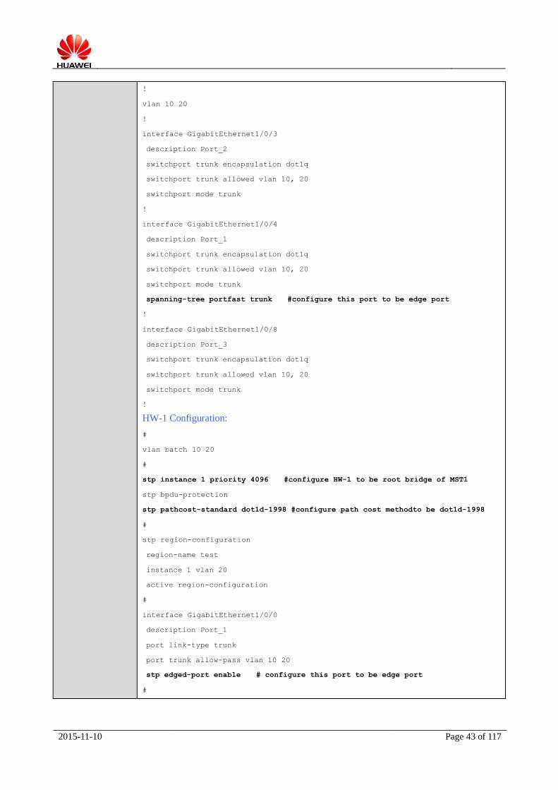
spanning-tree mst 0 priority 4096 #configure Cisco-1 to be root bridge of MST0
2015-11-10 Page 43 of 117
!
vlan 10 20
!
interface GigabitEthernet1/0/3
description Port_2
switchport trunk encapsulation dot1q
switchport trunk allowed vlan 10, 20
switchport mode trunk
!
interface GigabitEthernet1/0/4
description Port_1
switchport trunk encapsulation dot1q
switchport trunk allowed vlan 10, 20
switchport mode trunk
spanning-tree portfast trunk #configure this port to be edge port
!
interface GigabitEthernet1/0/8
description Port_3
switchport trunk encapsulation dot1q
switchport trunk allowed vlan 10, 20
switchport mode trunk
!
HW-1 Configuration:
#
vlan batch 10 20
#
stp instance 1 priority 4096 #configure HW-1 to be root bridge of MST1
stp bpdu-protection
stp pathcost-standard dot1d-1998 #configure path cost methodto be dot1d-1998
#
stp region-configuration
region-name test
instance 1 vlan 20
active region-configuration
#
interface GigabitEthernet1/0/0
description Port_1
port link-type trunk
port trunk allow-pass vlan 10 20
stp edged-port enable # configure this port to be edge port
#

2015-11-10 Page 44 of 117
interface GigabitEthernet1/0/2
description Port_3
port link-type trunk
port trunk allow-pass vlan 10 20
#
interface GigabitEthernet1/0/3
description Port_2
port link-type trunk
port trunk allow-pass vlan 10 20
#
HW-2 Configuration:
#
vlan batch 10 20
#
stp bpdu-protection
stp pathcost-standard dot1d-1998# configure path cost method to be dot1d-1998
#
stp region-configuration
region-name test
instance 1 vlan 20
active region-configuration
#
interface GigabitEthernet0/0/4
description Port_1
port link-type trunk
port trunk allow-pass vlan 10 20
#
interface GigabitEthernet0/0/22
description Port_2
port link-type trunk
port trunk allow-pass vlan 10 20
#
Signature by Customer
Signature by
HUAWEI
3.2.1.6 BPDU Guard Interoperability Test
Test Item BPDU Guard Interoperability Test
Test Objective To validate that HUAWEI and Cisco can realize the BPDU Guard interoperability test.

2015-11-10 Page 45 of 117
Test Setup Network Diagram:
Port_1
Tport_1
HW-1 Cisco-1
Tester
HW-2
Port_2 Port_2
Port_3 Port_3
Port_1 Port_2
Port_1
Tport_2
Pre-conditions:
1. All device work normally;
2. Establish the test environment according to the above diagram.
Test Procedure 1. Configure stp mode to be MST on Cisco-1, add all ports to VLAN 10 and VLAN 20 in
trunk mode, map VLAN 10 to MST0, map VLAN 20 to MST1, configure Cisco-1 to be root bridge of MST0;
2. Configure stp mode to be MSTP on HW-1 and HW-2, add all ports to VLAN 10 and
VLAN 20 in trunk mode, map VLAN 10 to MST0, map VLAN 20 to MST1, configure
HW-1 to be root bridge of MST1, configure the path cost method to be dot1d-1998 on
both devices, configure the Port connected with Cisco-1 on HW-1 and HW-2 to use
common fast transition mechanism;
3. Configure BPDU Guard function on HW-2 and Cisco-1, configure Port_2 on HW-2 to be edge port, check the interface status, obtain the expected result 1;
4. Configure Port_3 on Cisco-1 to be edge port, check the interface status, obtain the expected result 2.
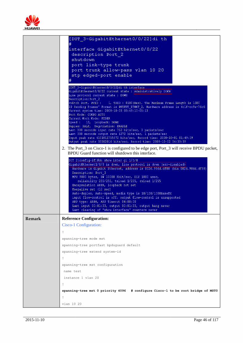
Expected Result 1. The Port_2 on HW-2 is configured to be edge port, Port_2 will receive BPDU packet,
BPDU Guard function will shutdown this interface;
2. The Port_3 on Cisco-1 is configured to be edge port, Port_3 will receive BPDU packet,
BPDU Guard function will shutdown this interface.
Actual Result 1. The Port_2 on HW-2 is configured to be edge port, Port_2 will receive BPDU packet,
BPDU Guard function will shutdown this interface;
2015-11-10 Page 46 of 117
2. The Port_3 on Cisco-1 is configured to be edge port, Port_3 will receive BPDU packet,
BPDU Guard function will shutdown this interface.
Remark Reference Configuration:
Cisco-1 Configuration:
!
spanning-tree mode mst
spanning-tree portfast bpduguard default
spanning-tree extend system-id
!
spanning-tree mst configuration
name test
instance 1 vlan 20
!
spanning-tree mst 0 priority 4096 # configure Cisco-1 to be root bridge of MST0
!
vlan 10 20
2015-11-10 Page 47 of 117
!
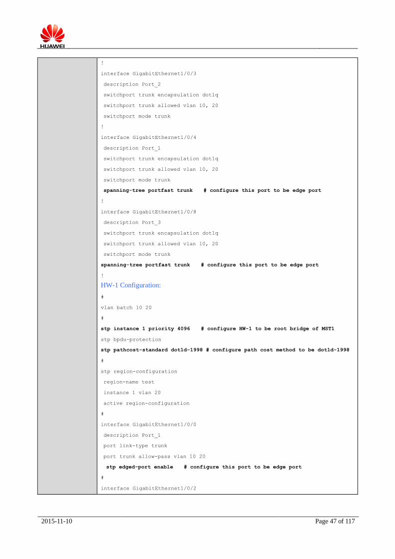
interface GigabitEthernet1/0/3
description Port_2
switchport trunk encapsulation dot1q
switchport trunk allowed vlan 10, 20
switchport mode trunk
!
interface GigabitEthernet1/0/4
description Port_1
switchport trunk encapsulation dot1q
switchport trunk allowed vlan 10, 20
switchport mode trunk
spanning-tree portfast trunk # configure this port to be edge port
!
interface GigabitEthernet1/0/8
description Port_3
switchport trunk encapsulation dot1q
switchport trunk allowed vlan 10, 20
switchport mode trunk
spanning-tree portfast trunk # configure this port to be edge port
!
HW-1 Configuration:
#
vlan batch 10 20
#
stp instance 1 priority 4096 # configure HW-1 to be root bridge of MST1
stp bpdu-protection
stp pathcost-standard dot1d-1998 # configure path cost method to be dot1d-1998
#
stp region-configuration
region-name test
instance 1 vlan 20
active region-configuration
#
interface GigabitEthernet1/0/0
description Port_1
port link-type trunk
port trunk allow-pass vlan 10 20
stp edged-port enable # configure this port to be edge port
#
interface GigabitEthernet1/0/2

2015-11-10 Page 48 of 117
description Port_3
port link-type trunk
port trunk allow-pass vlan 10 20
#
interface GigabitEthernet1/0/3
description Port_2
port link-type trunk
port trunk allow-pass vlan 10 20
#
HW-2 Configuration:
#
vlan batch 10 20
#
stp bpdu-protection
stp pathcost-standard dot1d-1998# configure path cost method to be dot1d-1998
#
stp region-configuration
region-name test
instance 1 vlan 20
active region-configuration
#
interface GigabitEthernet0/0/4
description Port_1
port link-type trunk
port trunk allow-pass vlan 10 20
#
interface GigabitEthernet0/0/22
description Port_2
port link-type trunk
port trunk allow-pass vlan 10 20
stp edged-port enable # configure this port to be edge port
#
Signature by Customer
Signature by
HUAWEI
3.2.1.7 ROOT Guard Interoperability Test
Test Item ROOT Guard Interoperability Test
Test Objective To validate that HUAWEI and Cisco can realize the ROOT Guard interoperability test.

2015-11-10 Page 49 of 117
Test Setup Network Diagram:
Port_1
Tport_1
HW-1 Cisco-1
Tester
HW-2
Port_2 Port_2
Port_3 Port_3
Port_1 Port_2
Port_1
Tport_2
Pre-conditions:
1. All device work normally;
2. Establish the test environment according to the above diagram.
Test Procedure 1. Configure stp mode to be MST on Cisco-1, add all ports to VLAN 10 and VLAN 20 in
trunk mode, map VLAN 10 to MST0, map VLAN 20 to MST1;
2. Configure stp mode to be MSTP on HW-1 and HW-2, add all ports to VLAN 10 and
VLAN 20 in trunk mode, map VLAN 10 to MST0, map VLAN 20 to MST1, configure
HW-1 to be root bridge of MST0 and MST1, configure the path cost method to be
dot1d-1998 on both devices, configure the Port connected with Cisco-1 on HW-1 and HW-2 to use common fast transition mechanism;
3. Enable root guard function on Port_2 and Port_3 on HW-1, then configure Cisco-1 to
be root bridge of MST0 and MST1, check MSTP status of HW-1, obtain the expected result 1.
Expected Result After enable root guard function on Port_2 and Port_3 on HW-1, then configure Cisco-1
to be root bridge of MST0 and MST1, then HW-1 designated port Port_2 and Port_3 will
receive BPDU packet with higher priority, root guard function will keep the port role still
to be designated port and set the stp state to be discarding.
Actual Result After enable root guard function on Port_2 and Port_3 on HW-1, then configure Cisco-1
to be root bridge of MST0 and MST1, then HW-1 designated port Port_2 and Port_3 will
receive BPDU packet with higher priority, root guard function will keep the port role still to be designated port and set the stp state to be discarding.

2015-11-10 Page 50 of 117
Remark Reference Configuration:
Cisco-1 Configuration:
!
spanning-tree mode mst
spanning-tree portfast bpduguard default
spanning-tree extend system-id
!
spanning-tree mst configuration
name test
instance 1 vlan 20
!
vlan 10 20
!
interface GigabitEthernet1/0/3
description Port_2
switchport trunk encapsulation dot1q
switchport trunk allowed vlan 10, 20
switchport mode trunk
!
interface GigabitEthernet1/0/4
description Port_1
switchport trunk encapsulation dot1q
switchport trunk allowed vlan 10, 20
switchport mode trunk
spanning-tree portfast trunk # configure this port to be edge port
!
interface GigabitEthernet1/0/8
description Port_3
switchport trunk encapsulation dot1q
switchport trunk allowed vlan 10, 20
switchport mode trunk
!
HW-1 Configuration:
#

2015-11-10 Page 51 of 117
vlan batch 10 20
#
stp instance 0priority 4096 # configure HW-1 to be root bridge of MST0
stp instance 1 priority 4096 # configure HW-1 to be root bridge of MST1
stp bpdu-protection
stp pathcost-standard dot1d-1998 # configure path cost method to be dot1d-1998
#
stp region-configuration
region-name test
instance 1 vlan 20
active region-configuration
#
interface GigabitEthernet1/0/0
description Port_1
port link-type trunk
port trunk allow-pass vlan 10 20
stp edged-port enable # configure this port to be edge port
#
interface GigabitEthernet1/0/2
description Port_3
port link-type trunk
port trunk allow-pass vlan 10 20
stp root-protection
#
interface GigabitEthernet1/0/3
description Port_2
port link-type trunk
port trunk allow-pass vlan 10 20
stp root-protection
#
HW-2 Configuration:
#
vlan batch 10 20
#
stp bpdu-protection
stp pathcost-standard dot1d-1998# configure path cost method to be dot1d-1998
#
stp region-configuration
region-name test
instance 1 vlan 20
active region-configuration
2015-11-10 Page 52 of 117
#
interface GigabitEthernet0/0/4
description Port_1
port link-type trunk
port trunk allow-pass vlan 10 20
#
interface GigabitEthernet0/0/22
description Port_2
port link-type trunk
port trunk allow-pass vlan 10 20
#
Signature by Customer
Signature by
HUAWEI
3.2.2 Eth-OAM Interoperability Test
3.2.2.1 802.3ah Eth-OAM--EFM Function Interoperability Test
Test Item 802.3ah Eth-OAM Interoperability Test
Test Objective To validate that HUAWEI and Cisco switches can realize the interoperability of 802.3ah
Eth-OAM function.
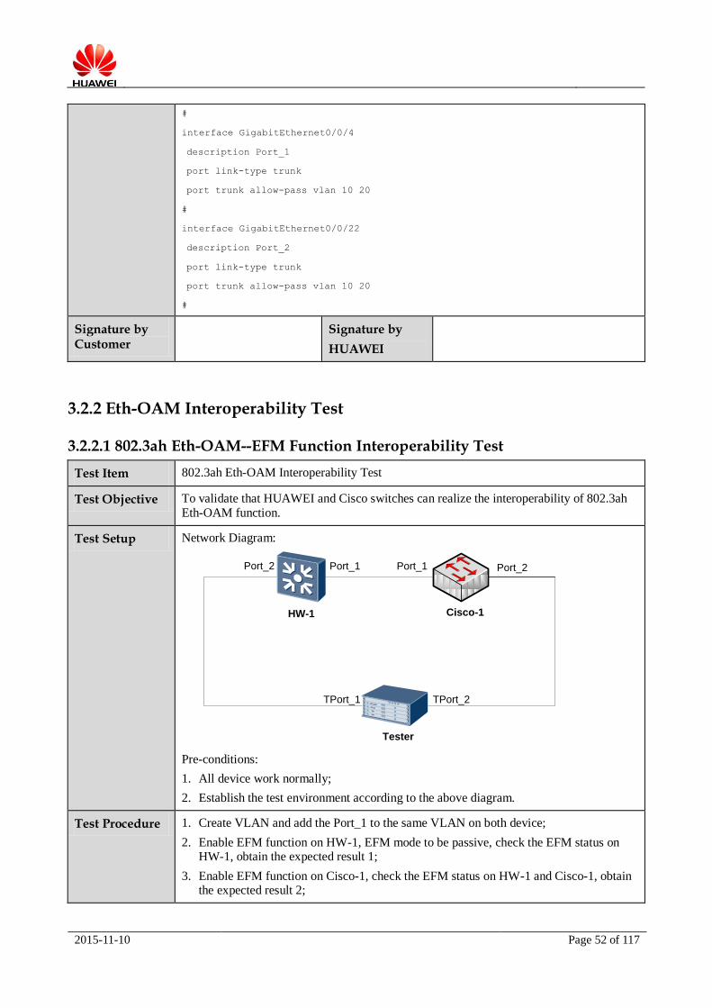
Test Setup Network Diagram:
Port_1
HW-1
Port_1
Cisco-1
TPort_1
Port_2
Tester
Port_2
TPort_2
Pre-conditions:
1. All device work normally;
2. Establish the test environment according to the above diagram.
Test Procedure 1. Create VLAN and add the Port_1 to the same VLAN on both device;
2. Enable EFM function on HW-1, EFM mode to be passive, check the EFM status on HW-1, obtain the expected result 1;
3. Enable EFM function on Cisco-1, check the EFM status on HW-1 and Cisco-1, obtain the expected result 2;
2015-11-10 Page 53 of 117
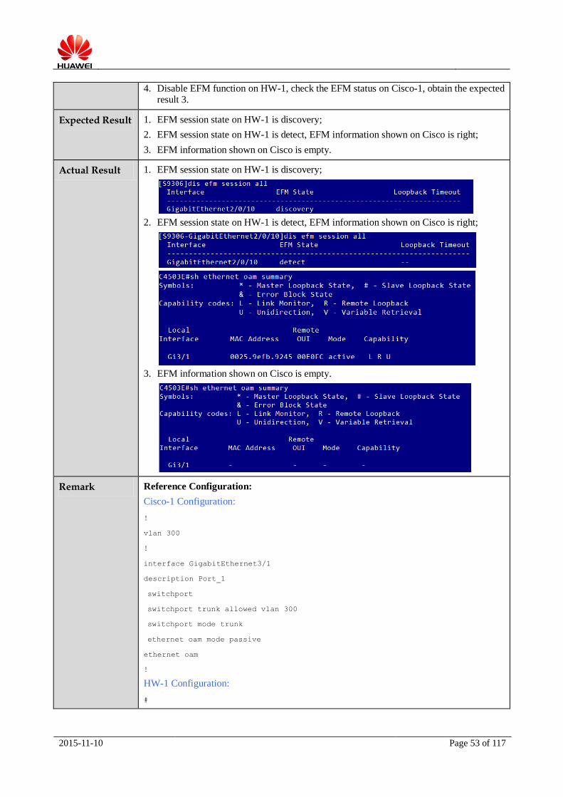
4. Disable EFM function on HW-1, check the EFM status on Cisco-1, obtain the expected result 3.
Expected Result 1. EFM session state on HW-1 is discovery;
2. EFM session state on HW-1 is detect, EFM information shown on Cisco is right;
3. EFM information shown on Cisco is empty.
Actual Result 1. EFM session state on HW-1 is discovery;
2. EFM session state on HW-1 is detect, EFM information shown on Cisco is right;
3. EFM information shown on Cisco is empty.
Remark Reference Configuration:
Cisco-1 Configuration:
!
vlan 300
!
interface GigabitEthernet3/1
description Port_1
switchport
switchport trunk allowed vlan 300
switchport mode trunk
ethernet oam mode passive
ethernet oam
!
HW-1 Configuration:
#

2015-11-10 Page 54 of 117
vlan 300
#
efm enable
#
interface GigabitEthernet2/0/9
description Port_2
port link-type trunk
undo port trunk allow-pass vlan 1
port trunk allow-pass vlan 300
#
interface GigabitEthernet2/0/10
description Port_1
port link-type trunk
port trunk allow-pass vlan 300
efm enable
#
Signature by Customer
Signature by HUAWEI
3.2.2.2 802.1ag Eth-OAM--CFM Function Interoperability Test
Test Item 802.1ag Eth-OAM Interoperability Test
Test Objective To validate that HUAWEI and Cisco switches can realize the interoperability of 802.1ag
Eth-OAM function.
Test Setup Network Diagram:
Port_1
HW-1
Port_1
Cisco-1
Pre-conditions:
1. All device work normally;
2. Establish the test environment according to the above diagram.
Test Procedure 1. Create VLAN and add the Port_1 to the same VLAN on both device;
2. Configure CFM function on HW-1 and Cisco-1, check CFM information on both devices, obtain the expected result 1;
3. Test MAC Ping and MAC Trace function on Cisco-1, obtain the expected result 2.
Expected Result 1. CFM status on both devices is right;
2. MAC Ping and MAC Trace result on Cisco-1 is successfully.

2015-11-10 Page 55 of 117
Actual Result 1. Check cfm configuration information on both device, the cfm status on HW-1 is UP;
Cisco-1 cfm domain information:
HW-1 cfm domain information:
Cisco-1 cfm status information:
HW-1 cfm status is UP:

2015-11-10 Page 56 of 117
2. MAC Ping and MAC Trace result on Cisco-1 is successfully.
MAC Ping
MAC Trace:
Remark Reference Configuration:
Cisco-1 Configuration:
!
vlan 603
!
ethernet cfm ieee
ethernet cfm global
ethernet cfm domain md1 level 3
service ma1 evc ma1 vlan 603 direction down
mep mpid 2
continuity-check
continuity-check interval 10s
!
ethernet evc ma1
!
interface GigabitEthernet1/7/13
description Port_1

2015-11-10 Page 57 of 117
switchport
switchport trunk allowed vlan 603
switchport mode trunk
ethernet cfm mep domain md1 mpid 2 vlan 603
!
HW-1 Configuration:
#
vlan 603
#
cfm md md1 level 3
ma ma1
map vlan 603
ccm-interval 10000
mep mep-id 1 interface GigabitEthernet4/1/6 outward
mep ccm-send mep-id 1 enable
remote-mep mep-id 2
remote-mep ccm-receive mep-id 2 enable
#
interface GigabitEthernet4/1/6
description Port_1
port link-type trunk
port trunk allow-pass vlan 603
#
Signature by Customer
Signature by HUAWEI
3.2.3 Link Aggregation Function Interoperability Test
3.2.3.1 Link Aggregation Function in LACP Mode
Test Item LACP Interoperability Test
Test Objective To validate that HUAWEI and Cisco switches can realize the interoperability of Link
Aggregation function in LACP mode.
Test Setup Network Diagram:

2015-11-10 Page 58 of 117
Port_1Port_2
HW-1
Tport_1 Tport_2
Tester
Port_1Port_2
Port_3 Port_3
Cisco-1
Pre-conditions:
1. All device work normally;
2. Establish the test environment according to the above diagram.
Test Procedure 1. Create Link Aggregation Group on Cisco-1 and HW-1, add Port_2 and Port_3 to Link
Aggregation Group on both devices, configure the mode to be LACP mode. Add Link
Aggregation Group to VLAN 601 in trunk mode;
2. Add Port_1 on both devices to VLAN 601;
3. Check Link Aggregation Group status, obtain the expected result 1;
4. Tester send bidirectional stream, check the Link Aggregation Group bandwidth, obtain the expected result 2;
5. Disconnect one active link, obtain the expected result 3.
Expected Result 1. The Link Aggregation Group is UP status;
2. Tester can receive two streams normally, the stream can load balance on two physical interfaces;
3. The stream can switchover to the active link normally.
Actual Result 1. The Link Aggregation Group is UP status:

2015-11-10 Page 59 of 117
2. Tester can receive two streams normally, the stream can load balance on two physical interfaces;
3. The stream can switchover to the active link normally.
Remark Reference Configuration:
Cisco-1 Configuration:
!
interface Port-channel4
switchport trunk encapsulation dot1q
switchport trunk allowed vlan 601
switchport mode trunk
!
interface GigabitEthernet1/0/3
description Port_2
2015-11-10 Page 60 of 117
switchport trunk encapsulation dot1q
switchport trunk allowed vlan 601
switchport mode trunk
channel-protocol lacp
channel-group 4 mode active
!
interface GigabitEthernet1/0/4
description Port_3
switchport trunk encapsulation dot1q
switchport trunk allowed vlan 601
switchport mode trunk
channel-protocol lacp
channel-group 4 mode active
!
HW-1 Configuration:
#
interface Eth-Trunk1
port link-type trunk
port trunk allow-pass vlan 601
mode lacp-static
load-balance src-mac
#
interface GigabitEthernet0/0/1
description Port_2
eth-trunk 1
#
interface GigabitEthernet0/0/3
description Port_3
eth-trunk 1
#
Signature by Customer
Signature by HUAWEI
3.2.3.2 Link Aggregation Function in Manual Mode
Test Item Manual Mode Interoperability Test
Test Objective To validate that HUAWEI and Cisco switches can realize the interoperability of Link
Aggregation function in Manual mode.
Test Setup Network Diagram:

2015-11-10 Page 61 of 117
Port_1Port_2
HW-1
Tport_1 Tport_2
Tester
Port_1Port_2
Port_3 Port_3
Cisco-1
Pre-conditions:
1. All device work normally;
2. Establish the test environment according to the above diagram.
Test Procedure 1. Create Link Aggregation Group on Cisco-1 and HW-1, add Port_2 and Port_3 to Link
Aggregation Group on both devices, configure the mode to be manual mode. Add Link
Aggregation Group to VLAN 601 in trunk mode;
2. Add Port_1 on both devices to VLAN 601;
3. Check Link Aggregation Group status, obtain the expected result 1;
4. Tester send bidirectional stream, check the Link Aggregation Group bandwidth, obtain the expected result 2;
5. Disconnect one active link, obtain the expected result 3.
Expected Result 1. The Link Aggregation Group is UP status;
2. Tester can receive two streams normally, the stream can load balance on two physical interfaces;
3. The stream can switchover to the active link normally.
Actual Result 1. The Link Aggregation Group is UP status;

2015-11-10 Page 62 of 117
2. Tester can receive two streams normally, the stream can load balance on two physical
interfaces;
3. The stream can switchover to the active link normally.
Remark Reference Configuration:
Cisco-1 Configuration:
!
interface Port-channel4
switchport trunk encapsulation dot1q
switchport trunk allowed vlan 601
switchport mode trunk
!
interface GigabitEthernet1/0/3
description Port_2
switchport trunk encapsulation dot1q
2015-11-10 Page 63 of 117
switchport trunk allowed vlan 601
switchport mode trunk
channel-group 4 mode on
!
interface GigabitEthernet1/0/4
description Port_3
switchport trunk encapsulation dot1q
switchport trunk allowed vlan 601
switchport mode trunk
channel-group 4 mode on
!
HW-1 Configuration:
#
interface Eth-Trunk1
port link-type trunk
port trunk allow-pass vlan 601
load-balance src-mac
#
interface GigabitEthernet0/0/1
description Port_2
eth-trunk 1
#
interface GigabitEthernet0/0/3
description Port_3
eth-trunk 1
#
Signature by Customer
Signature by HUAWEI
3.3 Layer 3 Function
3.3.1 IP Routing Interoperability Test
3.3.1.1 RIP Protocol Interoperability Test
Test Item RIP Basic Interoperability Test
Test Objective To validate that HUAWEI and Cisco switches can realize the interoperability of RIP
protocol.
Test Setup Network Diagram:

2015-11-10 Page 64 of 117
Port_2
HW-1
Port_2
Cisco-1
TPort_1
Port_1
Tester
Port_1
TPort_2
Pre-conditions:
1. All device work normally;
2. Establish the test environment according to the above diagram.
Test Procedure 1. Create VLAN 3 and assign IP address for interface vlanif 3 on HW-1;
2. Create VLAN 3 and assign IP address for interface vlanif 3 on Cisco-1;
3. Configure the basic RIP function on HW-1;
4. Configure the basic RIP function on Cisco-1, check the RIP peer status, obtain the
expected result 1;
5. Tester sends the stream using 10 routes with line speed, obtain the expected result 2.
Expected Result 1. The RIP peer can establish successfully and RIP route information on both devices is
right;
2. The 10 routes can be advertised on both devices successfully, Tester can receive the stream with line speed and there is no packet loss.
Actual Result 1. The RIP peer can establish successfully and RIP route information on both devices is
right;
The rip route information on HW-1:
The rip route information on Cisco:

2015-11-10 Page 65 of 117
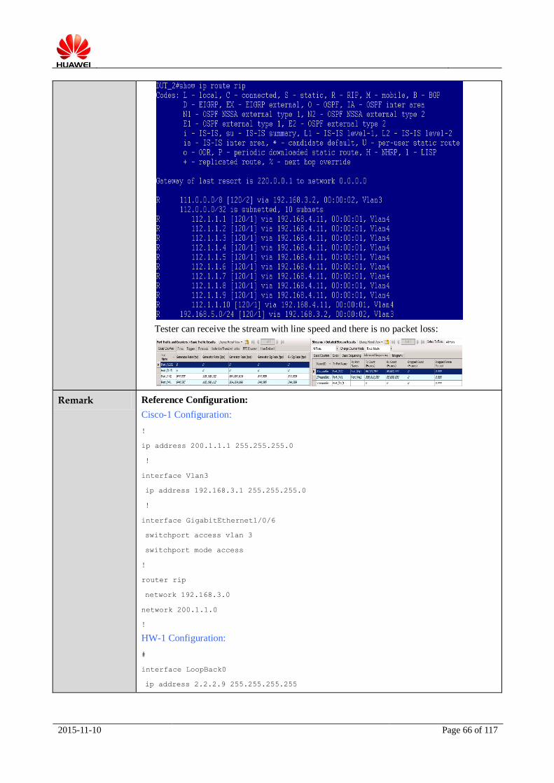
2. The 10 routes can be advertised on both devices successfully, Tester can receive the stream with line speed and there is no packet loss.
The rip route information on HW-1:
The rip route information on Cisco-1:
2015-11-10 Page 66 of 117
Tester can receive the stream with line speed and there is no packet loss:
Remark Reference Configuration:
Cisco-1 Configuration:
!
ip address 200.1.1.1 255.255.255.0
!
interface Vlan3
ip address 192.168.3.1 255.255.255.0
!
interface GigabitEthernet1/0/6
switchport access vlan 3
switchport mode access
!
router rip
network 192.168.3.0
network 200.1.1.0
!
HW-1 Configuration:
#
interface LoopBack0
ip address 2.2.2.9 255.255.255.255

2015-11-10 Page 67 of 117
#
interface Vlanif3
ip address 192.168.3.2 255.255.255.0
#
interface GigabitEthernet1/0/12
port link-type access
port default vlan 3
#
rip 1
network 2.0.0.0
network 192.168.3.0
#
Signature by Customer
Signature by HUAWEI
3.3.1.2 BGP Protocol Interoperability Test
Test Item BGP Basic Interoperability Test
Test Objective To validate that HUAWEI and Cisco switches can realize the interoperability of BGP
protocol.
Test Setup Network Diagram:
Port_2
HW-1
Port_2
Cisco-1
TPort_1
Port_1
Tester
Port_1
TPort_2
Pre-conditions:
1. All device work normally;
2. Establish the test environment according to the above diagram.
Test Procedure 1. Create VLAN 3 and assign IP address for interface vlanif 3 on HW-1;
2. Create VLAN 3 and assign IP address for interface vlanif 3 on Cisco-1;
3. Configure the basic BGP function on HW-1;
4. Configure the basic BGP function on Cisco-1, obtain the expected result 1.
2015-11-10 Page 68 of 117
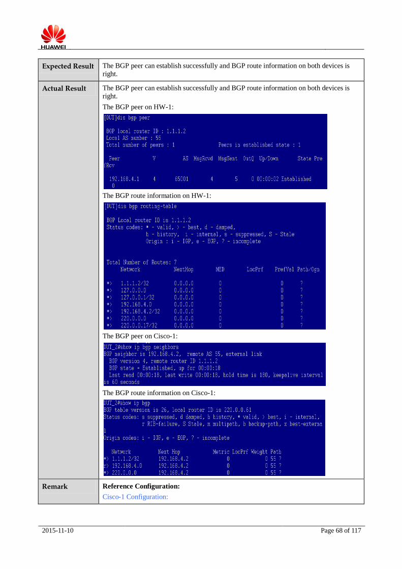
Expected Result The BGP peer can establish successfully and BGP route information on both devices is
right.
Actual Result The BGP peer can establish successfully and BGP route information on both devices is
right.
The BGP peer on HW-1:
The BGP route information on HW-1:
The BGP peer on Cisco-1:
The BGP route information on Cisco-1:
Remark Reference Configuration:
Cisco-1 Configuration:

2015-11-10 Page 69 of 117
!
interface Vlan4
ip address 192.168.4.1 255.255.255.0
!
interface GigabitEthernet1/0/7
switchport access vlan 4
switchport mode access
!
router bgp 65001
bgp log-neighbor-changes
neighbor 192.168.4.2 remote-as 55
no auto-summary
!
HW-1 Configuration:
#
interface Vlanif4
ip address 192.168.4.2 255.255.255.0
#
interface GigabitEthernet0/0/2
port link-type access
port default vlan 4
#
bgp 55
router-id 1.1.1.2
peer 192.168.4.1 as-number 65001
#
ipv4-family unicast
undo synchronization
import-route direct
peer 192.168.4.1 enable
#
Signature by Customer
Signature by HUAWEI
3.3.1.3 ISIS Protocol Interoperability Test
Test Item ISIS Basic Interoperability Test
Test Objective To validate that HUAWEI and Cisco switches can realize the interoperability of ISIS
protocol.

2015-11-10 Page 70 of 117
Test Setup Network Diagram:
Port_1
HW-1
Port_1
Cisco-1
Pre-conditions:
1. All device work normally;
2. Establish the test environment according to the above diagram.
Test Procedure 1. Create VLAN 200 and assign IP address for interface vlanif 200 on HW-1 and
Cisco-1;
2. Configure the basic ISIS function on HW-1 and Cisco-1, obtain the expected result 1.
Expected Result The ISIS neighbors can establish successfully on both device.
Actual Result The ISIS neighbors can establish successfully on both device
The ISIS neighbor information on Cisco-1:
The ISIS neighbor information on HW-1:
Remark Reference Configuration:
Cisco-1 Configuration:
!
2015-11-10 Page 71 of 117
interface GigabitEthernet 7/11
description Port_1
ip address 200.1.1.2 255.255.255.0
ip router isis 200
!
router isis 200
net 10.0000.0000.0002.00
is-type level-2-only
HW-1 Configuration:
#
interface Vlanif200
ip address 200.1.1.1 255.255.255.0
isis enable 200
isis authentication-mode md5 N`C55QK<`=/Q=^Q`MAF4<1!! level-2
#
interface GigabitEthernet 4/1/10
description Port_1
port link-type access
port default vlan 200
#
isis 200
is-level level-2
network-entity 10.0000.0000.0001.00
#
Signature by Customer
Signature by HUAWEI
3.3.1.4 ISIS MD5 Authentication Interoperability Test
Test Item ISIS MD5 Authentication Interoperability Test
Test Objective To validate that HUAWEI and Cisco switches can realize the interoperability of ISIS
MD5 Authentication test.
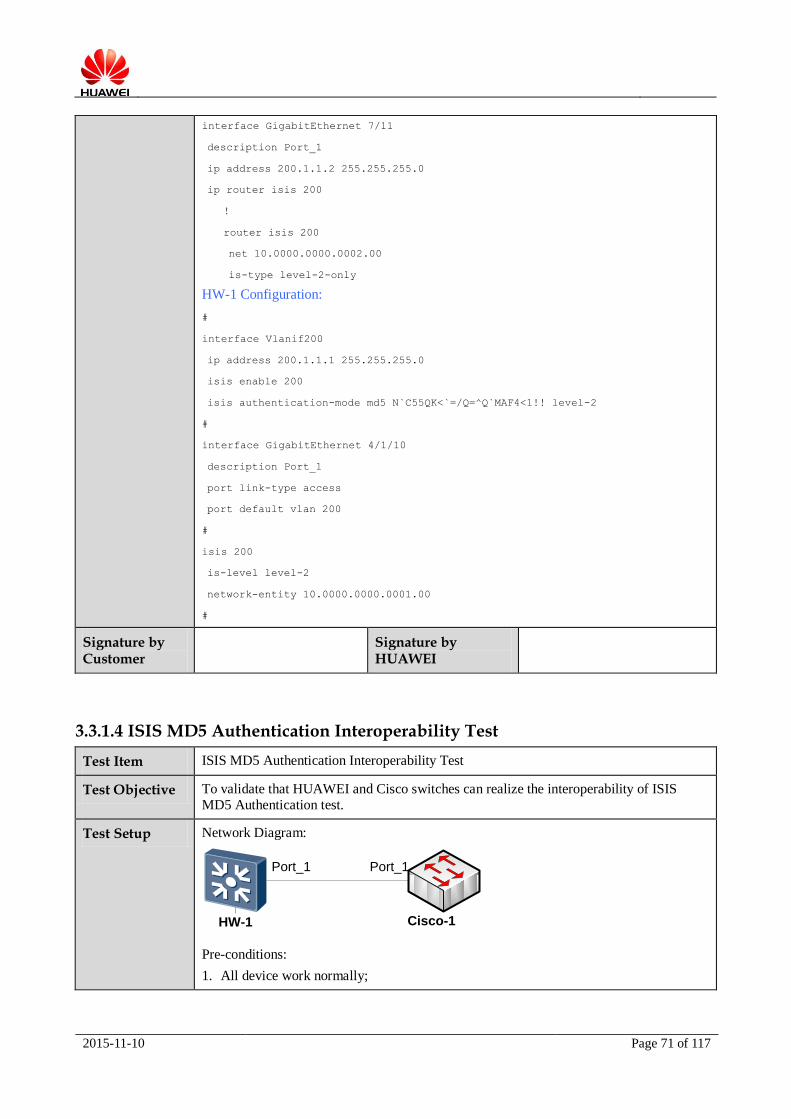
Test Setup Network Diagram:
Port_1
HW-1
Port_1
Cisco-1
Pre-conditions:
1. All device work normally;
2015-11-10 Page 72 of 117
2. Establish the test environment according to the above diagram.
Test Procedure 1. Create VLAN 200 and assign IP address for interface vlanif 200 on HW-1 and
Cisco-1;
2. Configure the basic ISIS function on HW-1 and Cisco-1;
3. Configure ISIS MD5 authentication on interfaces on HW-1 and Cisco-1;
4. Check ISIS neighbor information on HW-1 and Cisco-1, obtain the expected result 1.
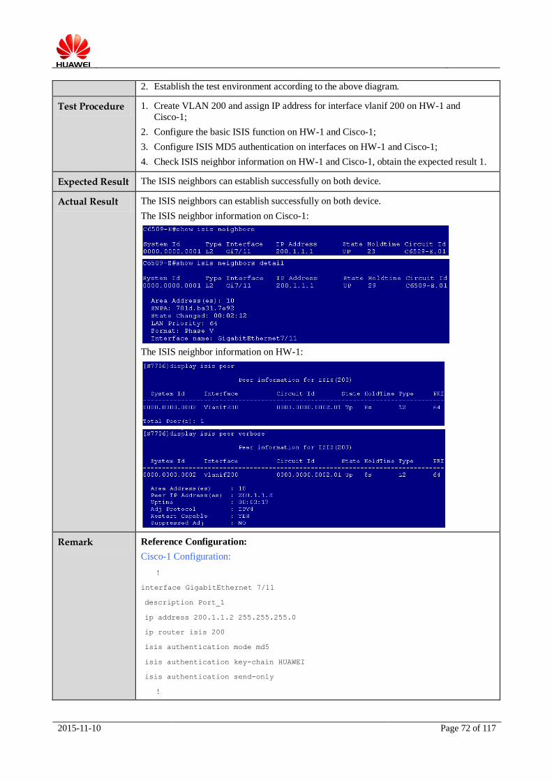
Expected Result The ISIS neighbors can establish successfully on both device.
Actual Result The ISIS neighbors can establish successfully on both device.
The ISIS neighbor information on Cisco-1:
The ISIS neighbor information on HW-1:
Remark Reference Configuration:
Cisco-1 Configuration:
!
interface GigabitEthernet 7/11
description Port_1
ip address 200.1.1.2 255.255.255.0
ip router isis 200
isis authentication mode md5
isis authentication key-chain HUAWEI
isis authentication send-only
!
2015-11-10 Page 73 of 117
router isis 200
net 10.0000.0000.0002.00
is-type level-2-only
HW-1 Configuration:
#
interface Vlanif200
ip address 200.1.1.1 255.255.255.0
isis enable 200
isis authentication-mode md5 N`C55QK<`=/Q=^Q`MAF4<1!! send-only
#
interface GigabitEthernet 4/1/10
description Port_1
port link-type access
port default vlan 200
#
isis 200
is-level level-2
network-entity 10.0000.0000.0001.00
#
Signature by Customer
Signature by HUAWEI
3.3.1.5 OSPF Protocol Interoperability Test
Test Item OSPF Basic Interoperability Test
Test Objective To validate that HUAWEI and Cisco switches can realize the interoperability of OSPF
protocol.
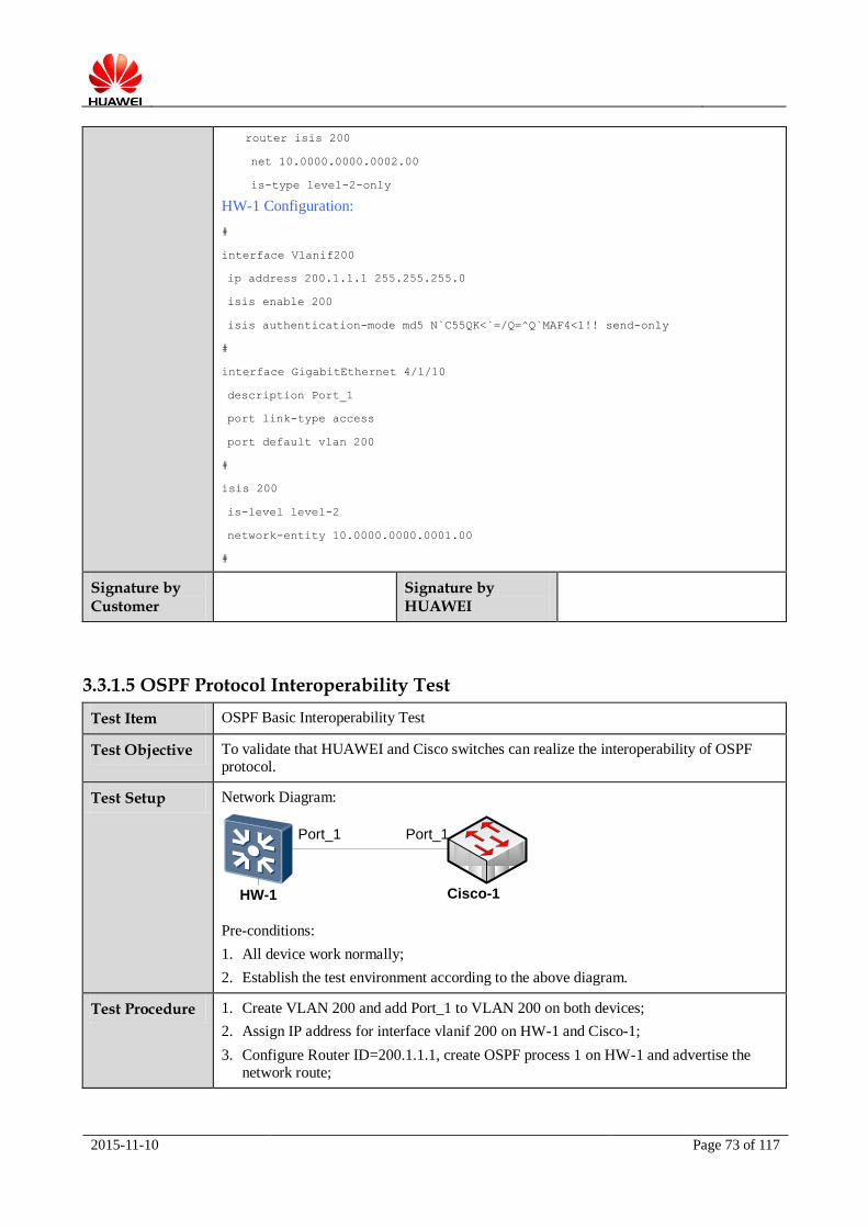
Test Setup Network Diagram:
Port_1
HW-1
Port_1
Cisco-1
Pre-conditions:
1. All device work normally;
2. Establish the test environment according to the above diagram.
Test Procedure 1. Create VLAN 200 and add Port_1 to VLAN 200 on both devices;
2. Assign IP address for interface vlanif 200 on HW-1 and Cisco-1;
3. Configure Router ID=200.1.1.1, create OSPF process 1 on HW-1 and advertise the
network route;

2015-11-10 Page 74 of 117
4. Configure Router ID=200.1.1.2, create OSPF process 1 on Cisco-1 and advertise the network route;
5. Check OSPF neighbors on both devices, obtain the expected result 1.
Expected Result The OSPF neighbors can establish successfully on both devices.
Actual Result The OSPF neighbors can establish successfully on both devices.
The OSPF neighbor information on Cisco-1:
The OSPF neighbor information on HW-1:
Remark Reference Configuration:
Cisco-1 Configuration:
!
interface GigabitEthernet1/0/5
description Port_1
switchport access vlan 200
switchport mode access
!
interface Vlan200
ip address 200.1.1.2 255.255.255.0
!

2015-11-10 Page 75 of 117
router ospf 1
router-id 200.1.1.2
network 200.1.1.0 0.0.0.255 area 0
HW-1 Configuration:
#
interface Vlanif200
ip address 200.1.1.1 255.255.255.0
#
interface GigabitEthernet2/0/45
description Port_1
port link-type access
port default vlan 200
#
ospf 1 router-id 200.1.1.1
area 0.0.0.0
network 200.1.1.0 0.0.0.255
#
Signature by Customer
Signature by HUAWEI
3.3.1.6 OSPF MD5 Authentication Interoperability Test
Test Item OSPF MD5 Authentication Interoperability Test
Test Objective To validate that HUAWEI and Cisco switches can realize the interoperability of OSPF
MD5 Authentication test.
Test Setup Network Diagram:
Port_1
HW-1
Port_1
Cisco-1
Pre-conditions:
1. All device work normally;
2. Establish the test environment according to the above diagram.
Test Procedure 1. Create VLAN 200 and add Port_1 to VLAN 200 on both devices;
2. Assign IP address for interface vlanif 200 on HW-1 and Cisco-1;
3. Configure Router ID=200.1.1.1, create OSPF process 1 on HW-1 and advertise the network route;
4. Configure Router ID=200.1.1.2, create OSPF process 1 on Cisco-1 and advertise the
network route;
2015-11-10 Page 76 of 117
5. Configure OSPF MD5 authentication on OSPF area;
6. Check OSPF neighbor on HW-1 and Cisco-1, obtain the expected result 1;
7. Disable OSPF MD5 authentication on OSPF area, enable OSPF MD5 authentication on interfaces;
8. Check OSPF neighbor on HW-1 and Cisco-1, obtain the expected result 1.
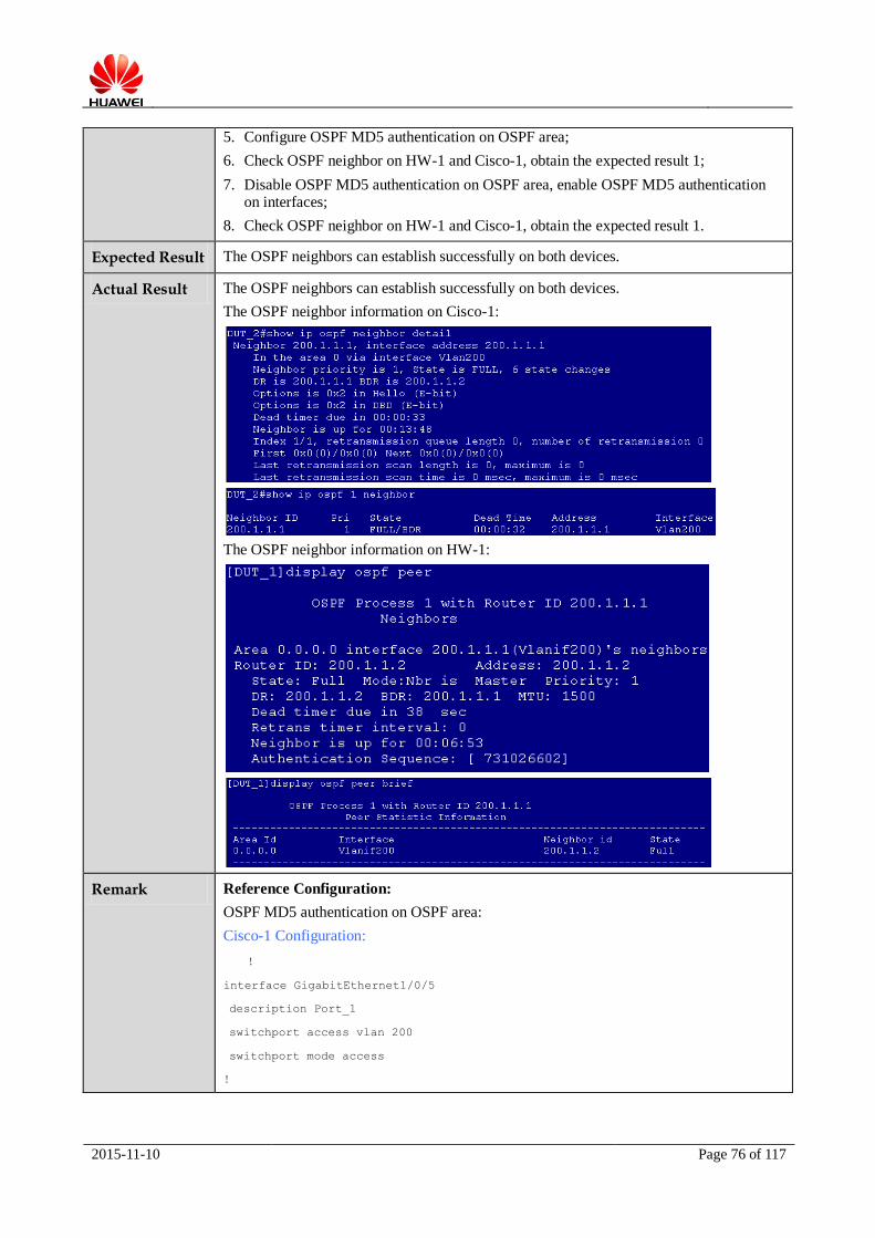
Expected Result The OSPF neighbors can establish successfully on both devices.
Actual Result The OSPF neighbors can establish successfully on both devices.
The OSPF neighbor information on Cisco-1:
The OSPF neighbor information on HW-1:
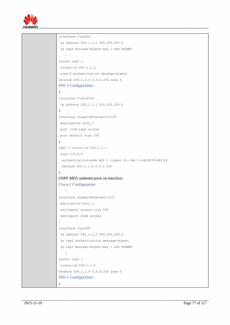
Remark Reference Configuration:
OSPF MD5 authentication on OSPF area:
Cisco-1 Configuration:
!
interface GigabitEthernet1/0/5
description Port_1
switchport access vlan 200
switchport mode access
!
2015-11-10 Page 77 of 117
interface Vlan200
ip address 200.1.1.2 255.255.255.0
ip ospf message-digest-key 1 md5 HUAWEI
!
router ospf 1
router-id 200.1.1.2
area 0 authentication message-digest
network 200.1.1.0 0.0.0.255 area 0
HW-1 Configuration:
#
interface Vlanif200
ip address 200.1.1.1 255.255.255.0
#
interface GigabitEthernet2/0/45
description Port_1
port link-type access
port default vlan 200
#
ospf 1 router-id 200.1.1.1
area 0.0.0.0
authentication-mode md5 1 cipher Vv.-9m|l}:=H)H2[EInBVir#
network 200.1.1.0 0.0.0.255
#
OSPF MD5 authentication on interface:
Cisco-1 Configuration:
!
interface GigabitEthernet1/0/5
description Port_1
switchport access vlan 200
switchport mode access
!
interface Vlan200
ip address 200.1.1.2 255.255.255.0
ip ospf authentication message-digest
ip ospf message-digest-key 1 md5 HUAWEI
!
router ospf 1
router-id 200.1.1.2
network 200.1.1.0 0.0.0.255 area 0
HW-1 Configuration:
#

2015-11-10 Page 78 of 117
interface Vlanif200
ip address 200.1.1.1 255.255.255.0
ospf authentication-mode md5 1 cipher }[b}4u(G<FjKUGU-KkpBz1K#
#
interface GigabitEthernet2/0/45
description Port_1
port link-type access
port default vlan 200
#
ospf 1 router-id 200.1.1.1
area 0.0.0.0
network 200.1.1.0 0.0.0.255
#
Signature by Customer
Signature by HUAWEI
3.3.2 NTP Function
3.3.2.1 NTP Client Interoperability Test
Test Item NTP Client Interoperability Test
Test Objective To validate that HUAWEI and Cisco switches can realize the interoperability of NTP
client function.
Test Setup Network Diagram:
Pre-conditions:
1. All device work normally;
2. Establish the test environment according to the above diagram.
Test Procedure 1. Create VLAN and assign IP address for VLAN interface on both devices to make route
reachable;
2. Specify the local clock of Cisco-1 as the primary clock;
3. Configure Cisco-1 as the Unicast NTP server on HW-1, check NTP status, obtain the expected result 1;
4. Configure HW-1 as NTP broadcast client on VLAN interface, configure Cisco-1 as the
NTP broadcast server on VLAN interface, check NTP status, obtain the expected result 1;
HW-1 Cisco-1
Port_1 Port_1
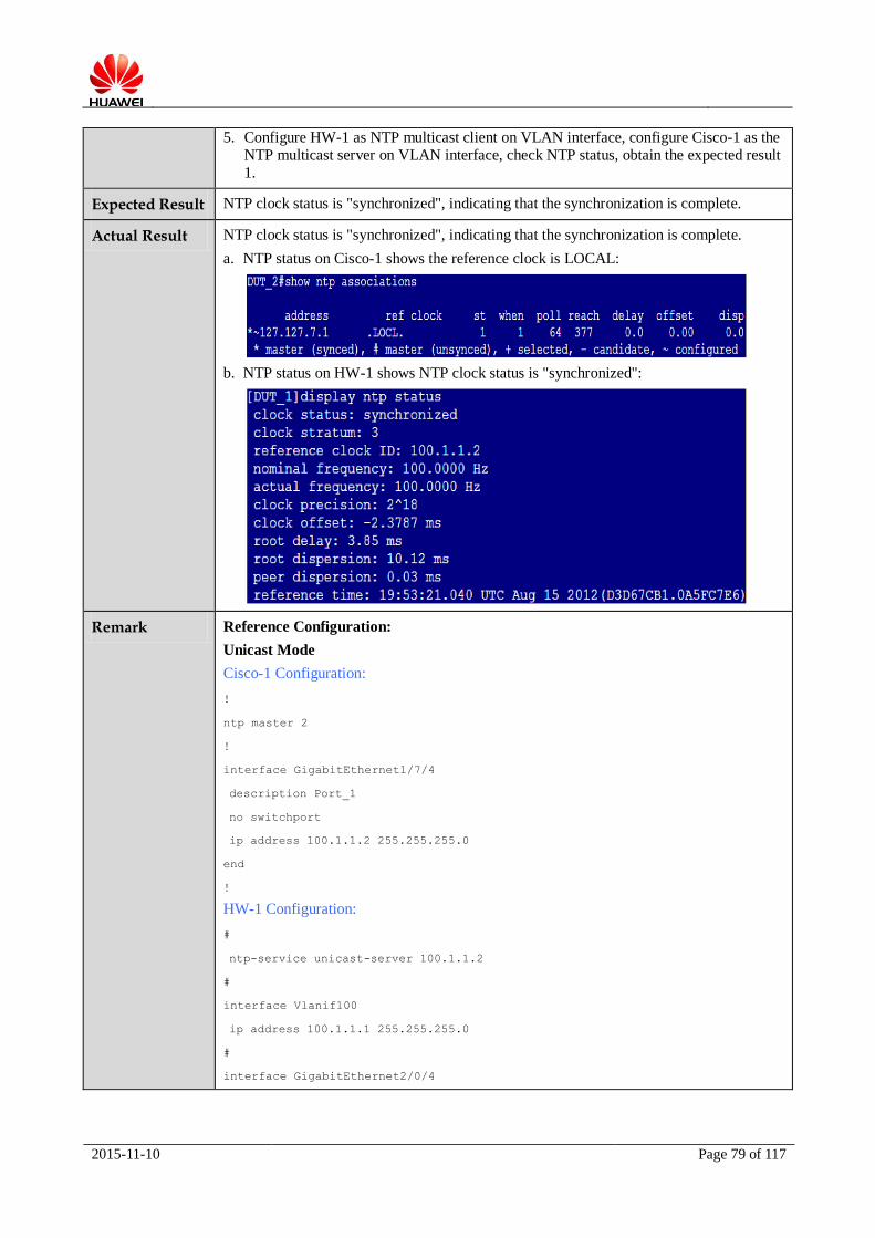
2015-11-10 Page 79 of 117
5. Configure HW-1 as NTP multicast client on VLAN interface, configure Cisco-1 as the
NTP multicast server on VLAN interface, check NTP status, obtain the expected result
1.
Expected Result NTP clock status is "synchronized", indicating that the synchronization is complete.
Actual Result NTP clock status is "synchronized", indicating that the synchronization is complete.
a. NTP status on Cisco-1 shows the reference clock is LOCAL:
b. NTP status on HW-1 shows NTP clock status is "synchronized":
Remark Reference Configuration:
Unicast Mode
Cisco-1 Configuration:
!
ntp master 2
!
interface GigabitEthernet1/7/4
description Port_1
no switchport
ip address 100.1.1.2 255.255.255.0
end
!
HW-1 Configuration:
#
ntp-service unicast-server 100.1.1.2
#
interface Vlanif100
ip address 100.1.1.1 255.255.255.0
#
interface GigabitEthernet2/0/4
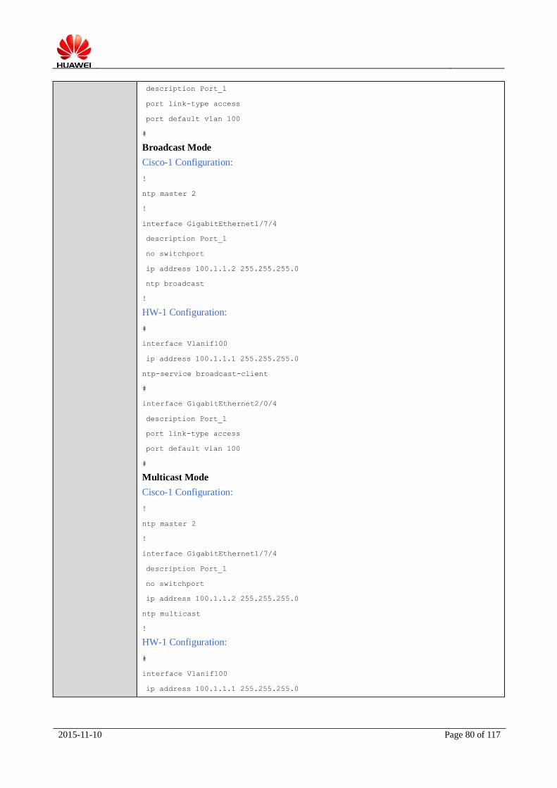
2015-11-10 Page 80 of 117
description Port_1
port link-type access
port default vlan 100
#
Broadcast Mode
Cisco-1 Configuration:
!
ntp master 2
!
interface GigabitEthernet1/7/4
description Port_1
no switchport
ip address 100.1.1.2 255.255.255.0
ntp broadcast
!
HW-1 Configuration:
#
interface Vlanif100
ip address 100.1.1.1 255.255.255.0
ntp-service broadcast-client
#
interface GigabitEthernet2/0/4
description Port_1
port link-type access
port default vlan 100
#
Multicast Mode
Cisco-1 Configuration:
!
ntp master 2
!
interface GigabitEthernet1/7/4
description Port_1
no switchport
ip address 100.1.1.2 255.255.255.0
ntp multicast
!
HW-1 Configuration:
#
interface Vlanif100
ip address 100.1.1.1 255.255.255.0

2015-11-10 Page 81 of 117
ntp-service multicast-client
#
interface GigabitEthernet2/0/4
description Port_1
port link-type access
port default vlan 100
#
Signature by Customer
Signature by
HUAWEI
3.3.2.2 NTP Server Interoperability Test
Test Item NTP Server Interoperability Test
Test Objective To validate that HUAWEI and Cisco switches can realize the interoperability of NTP
server function.
Test Setup Network Diagram:
Pre-conditions:
1. All device work normally;
2. Establish the test environment according to the above diagram.
Test Procedure 1. Create VLAN and assign IP address for VLAN interface on both devices to make route
reachable;
2. Specify the local clock of HW-1 as the primary clock;
3. Configure HW-1 as the Unicast NTP server on Cisoc-1, check NTP status, obtain the expected result 1;
4. Configure Cisco-1 as NTP broadcast client on VLAN interface, configure HW-1 as the
NTP broadcast server on VLAN interface, check NTP status, obtain the expected result
1;
5. Configure Cisco-1 as NTP multicast client on VLAN interface, configure HW-1 as the
NTP multicast server on VLAN interface, check NTP status, obtain the expected result 1.
Expected Result NTP clock status is "synchronized", indicating that the synchronization is complete.
Actual Result NTP clock status is "synchronized", indicating that the synchronization is complete.
a. NTP status on Cisco-1 shows the reference clock is NTP server clock:
HW-1 Cisco-1
Port_1 Port_1
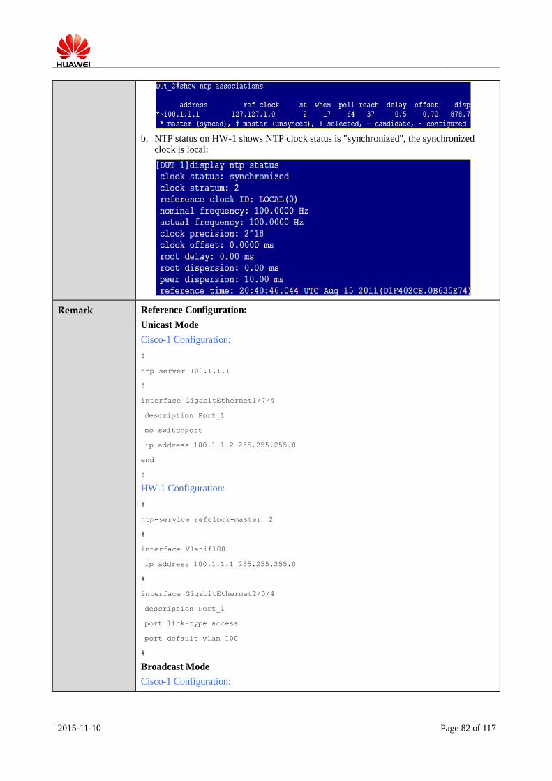
2015-11-10 Page 82 of 117
b. NTP status on HW-1 shows NTP clock status is "synchronized", the synchronized clock is local:
Remark Reference Configuration:
Unicast Mode
Cisco-1 Configuration:
!
ntp server 100.1.1.1
!
interface GigabitEthernet1/7/4
description Port_1
no switchport
ip address 100.1.1.2 255.255.255.0
end
!
HW-1 Configuration:
#
ntp-service refclock-master 2
#
interface Vlanif100
ip address 100.1.1.1 255.255.255.0
#
interface GigabitEthernet2/0/4
description Port_1
port link-type access
port default vlan 100
#
Broadcast Mode
Cisco-1 Configuration:
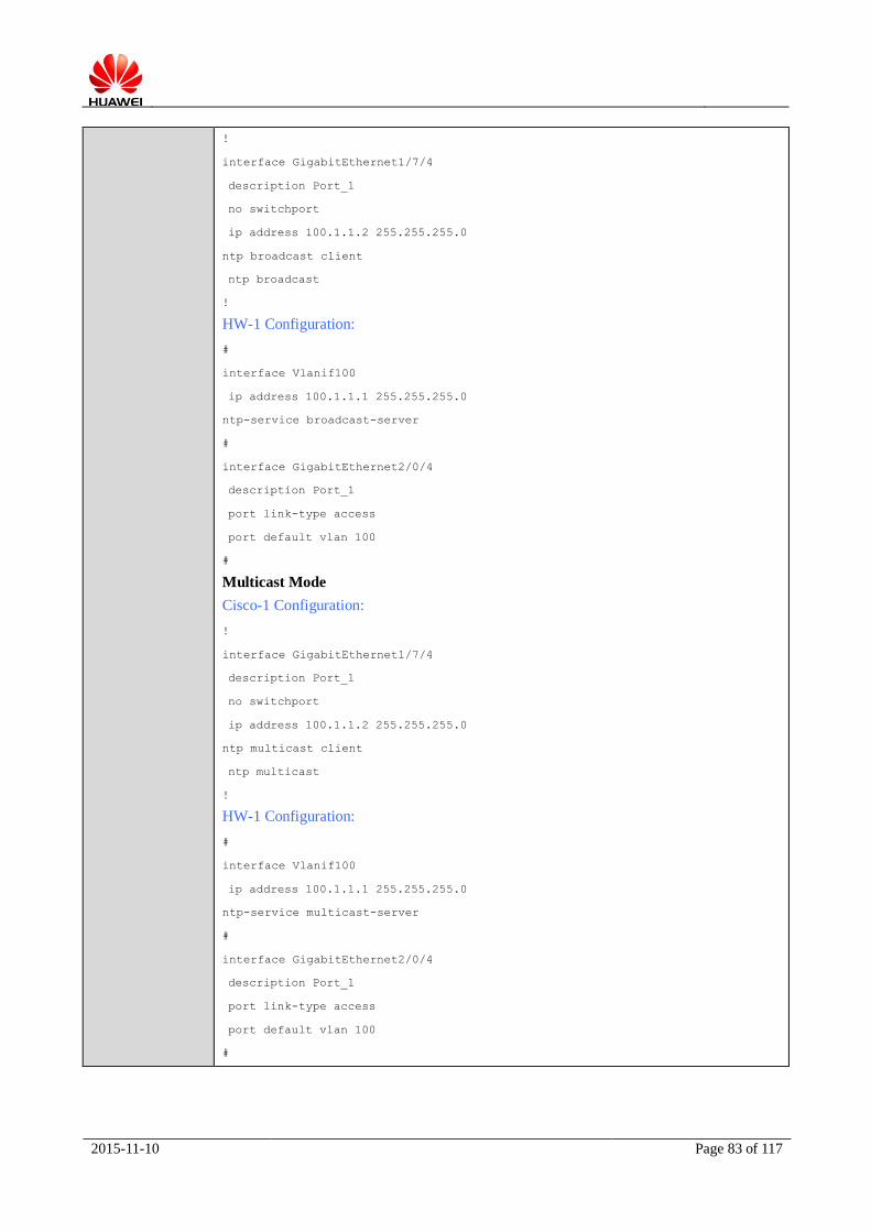
2015-11-10 Page 83 of 117
!
interface GigabitEthernet1/7/4
description Port_1
no switchport
ip address 100.1.1.2 255.255.255.0
ntp broadcast client
ntp broadcast
!
HW-1 Configuration:
#
interface Vlanif100
ip address 100.1.1.1 255.255.255.0
ntp-service broadcast-server
#
interface GigabitEthernet2/0/4
description Port_1
port link-type access
port default vlan 100
#
Multicast Mode
Cisco-1 Configuration:
!
interface GigabitEthernet1/7/4
description Port_1
no switchport
ip address 100.1.1.2 255.255.255.0
ntp multicast client
ntp multicast
!
HW-1 Configuration:
#
interface Vlanif100
ip address 100.1.1.1 255.255.255.0
ntp-service multicast-server
#
interface GigabitEthernet2/0/4
description Port_1
port link-type access
port default vlan 100
#

2015-11-10 Page 84 of 117
Signature by Customer
Signature by
HUAWEI
3.3.2.3 NTP Authentication Interoperability Test
Test Item NTP Authentication Interoperability Test
Test Objective To validate that HUAWEI and Cisco switches can realize the interoperability of NTP
authentication function.
Test Setup Network Diagram:
Pre-conditions:
1. All device work normally;
2. Establish the test environment according to the above diagram.
Test Procedure 1. Create VLAN and assign IP address for VLAN interface on both devices to make route
reachable;
2. Specify the local clock of HW-1 as the primary clock, set the clock stratum, enable the NTP authentication function, configure the authentication key 100 to be HUAWEI;
3. Configure HW-1 as the Unicast NTP server on Cisoc-1, enable the NTP authentication function, configure the wrong authentication key, obtain the expected result 1;
4. Configure the right authentication key on Cisco-1, obtain the expected result 2.
Expected Result NTP clock status is "synchronized", indicating that the synchronization is complete.
Actual Result NTP clock status is "synchronized", indicating that the synchronization is complete.
a. When the authentication key is wrong, the NTP status on Cisco-1 shows NTP clock
status is "unsynchronized":
b. When the authentication key is right, the NTP status on Cisco-1 shows NTP clock status is "synchronized":
HW-1 Cisco-1
Port_1 Port_1

2015-11-10 Page 85 of 117
c. NTP status on HW-1 shows NTP clock status is "synchronized", the synchronized clock is local:
Remark Reference Configuration:
Unicast Mode
Cisco-1 Configuration:
!
ntp server 100.1.1.1
!
interface GigabitEthernet1/7/4
description Port_1
no switchport
ip address 100.1.1.2 255.255.255.0
end
!
ntp authentication-key 100 md5 11010C04001702 7
ntp authenticate
ntp trusted-key 100
ntp server 100.1.1.1 key 100
!
HW-1 Configuration:
#
ntp-service authentication enable
ntp-service authentication-keyid 100 authentication-mode md5 N`C55QK<`=/Q=^Q`MA
F4<1!!
ntp-service refclock-master 2
#
interface Vlanif100
ip address 100.1.1.1 255.255.255.0
#

2015-11-10 Page 86 of 117
interface GigabitEthernet2/0/4
description Port_1
port link-type access
port default vlan 100
#
Signature by Customer
Signature by
HUAWEI
3.3.3 MPLS VPN Interoperability Test
3.3.3.1 L3VPN Interoperability Test
Test Item L3VPN Interoperability Test
Test Objective To validate that HUAWEI and Cisco switches can realize the interoperability of L3VPN
function.
Test Setup Network Diagram:
Pre-conditions:
1. All device work normally;
2. Establish the test environment according to the above diagram.
Test Procedure 1. Configure IGP protocol, configure MPLS basic function and MPLS LDP between
HW-1 and Cisco-1, configure BGP and VRF;
2. Check private network route, validate IP routing reachable, obtain the expected result 1, 2, 3.
Expected Result 1. The remote PE loopback route can be seen normally, LDP session status is right, the
BGP peer can be established normally;
2. The remote private network route can be seen on Cisco-1, Tester as CEs can ping each
other successfully;
3. The Tester port connected with Cisco-1 advertises the route, the routes imported to
HW-1 Cisco-1
Port_2 Port_2Port_1 Port_1
Tport_1 Tport_2

2015-11-10 Page 87 of 117
private network instance. The private network route can be seen on HW-1 vpn
instance. The Tester port connected with HW-1 send streams to private network route,
the stream can be received normally.
Actual Result 1. The remote PE loopback route can be seen normally, LDP session status is right, the
BGP peer can be established normally;
a. The LDP session status:
b. The BGP peer information:
2. The remote private network route can be seen on Cisco-1, Tester as CEs can ping each other successfully;

2015-11-10 Page 88 of 117
a. The IP routing table of wy instance on Cisco-1:
b. Tester as CEs can ping each other successfully:
3. The Tester port connected with Cisco-1 advertises the route, the routes imported to
private network instance. The private network route can be seen on HW-1 vpn
instance. The Tester port connected with HW-1 send streams to private network route, the stream can be received normally.
a. The Tester port connected with Cisco-1 simulate BGP router to advertises the route, import 5 BGP route, check routing-table of VPN instance on HW-1:

2015-11-10 Page 89 of 117
b. The Tester port connected with HW-1 send streams to private network route, the
stream can be received normally:
Remark Reference Configuration:
HW-1 Configuration:
#
ip vpn-instance wy
route-distinguisher 100:1
vpn-target 1:1 export-extcommunity
vpn-target 1:1 import-extcommunity
#
mpls lsr-id 3.3.3.3
mpls
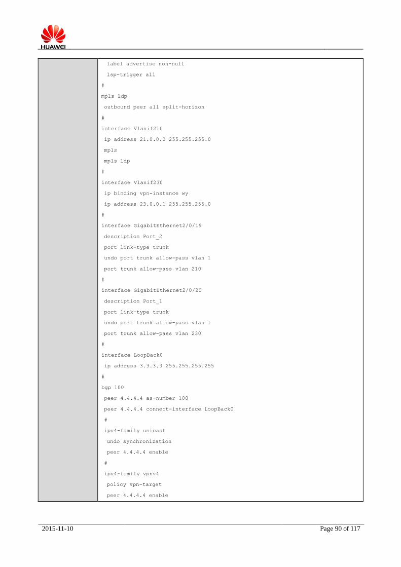
2015-11-10 Page 90 of 117
label advertise non-null
lsp-trigger all
#
mpls ldp
outbound peer all split-horizon
#
interface Vlanif210
ip address 21.0.0.2 255.255.255.0
mpls
mpls ldp
#
interface Vlanif230
ip binding vpn-instance wy
ip address 23.0.0.1 255.255.255.0
#
interface GigabitEthernet2/0/19
description Port_2
port link-type trunk
undo port trunk allow-pass vlan 1
port trunk allow-pass vlan 210
#
interface GigabitEthernet2/0/20
description Port_1
port link-type trunk
undo port trunk allow-pass vlan 1
port trunk allow-pass vlan 230
#
interface LoopBack0
ip address 3.3.3.3 255.255.255.255
#
bgp 100
peer 4.4.4.4 as-number 100
peer 4.4.4.4 connect-interface LoopBack0
#
ipv4-family unicast
undo synchronization
peer 4.4.4.4 enable
#
ipv4-family vpnv4
policy vpn-target
peer 4.4.4.4 enable

2015-11-10 Page 91 of 117
#
ipv4-family vpn-instance wy
import-route direct
peer 23.0.0.2 as-number 65001
#
ospf 1
area 0.0.0.0
network 3.3.3.3 0.0.0.0
network 21.0.0.0 0.0.0.255
#
Cisco-1 Configuration:
!
ip vrf wy
rd 100:1
route-target export 1:1
route-target import 1:1
!
Mpls ip
mpls label protocol ldp
!
interface Loopback0
ip address 4.4.4.4 255.255.255.255
!
interface GigabitEthernet1/7/19
description Port_2
switchport
switchport trunk allowed vlan 210
switchport mode trunk
!
interface GigabitEthernet1/7/20
description Port_1
switchport
switchport trunk allowed vlan 220
switchport mode trunk
!
interface Vlan210
ip address 21.0.0.1 255.255.255.0
mpls ip
!
interface Vlan220
ip vrf forwarding wy
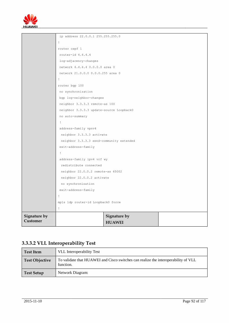
2015-11-10 Page 92 of 117
ip address 22.0.0.1 255.255.255.0
!
router ospf 1
router-id 4.4.4.4
log-adjacency-changes
network 4.4.4.4 0.0.0.0 area 0
network 21.0.0.0 0.0.0.255 area 0
!
router bgp 100
no synchronization
bgp log-neighbor-changes
neighbor 3.3.3.3 remote-as 100
neighbor 3.3.3.3 update-source Loopback0
no auto-summary
!
address-family vpnv4
neighbor 3.3.3.3 activate
neighbor 3.3.3.3 send-community extended
exit-address-family
!
address-family ipv4 vrf wy
redistribute connected
neighbor 22.0.0.2 remote-as 65002
neighbor 22.0.0.2 activate
no synchronization
exit-address-family
!
mpls ldp router-id Loopback0 force
!
Signature by Customer
Signature by
HUAWEI
3.3.3.2 VLL Interoperability Test
Test Item VLL Interoperability Test
Test Objective To validate that HUAWEI and Cisco switches can realize the interoperability of VLL
function.
Test Setup Network Diagram:

2015-11-10 Page 93 of 117
Pre-conditions:
1. All device work normally;
2. Establish the test environment according to the above diagram.
Test Procedure 1. Configure IGP protocol on both devices to make IGP routing reachable;
2. Configure MPLS basic function and LDP on both devices, check MPLS forwarding
table, obtain the expected result 1;
3. Enable MPLS L2VPN and create L2VC function, check L2VC status, obtain the expected result 2;
4. Tester Tport_1 and Tport_2 simulate two hosts as CEs to ping each other, obtain the expected result 3.
Expected Result 1. MPLS LDP and LSP work normally;
2. The L2VC status is UP;
3. Two CEs can ping each other successfully, the bidirectional unicast stream can be received normally.
Actual Result 1. MPLS LDP and LSP work normally;
a. The LDP SESSION status:
HW-1 Cisco-1
Port_2 Port_2Port_1 Port_1
Tport_1 Tport_2
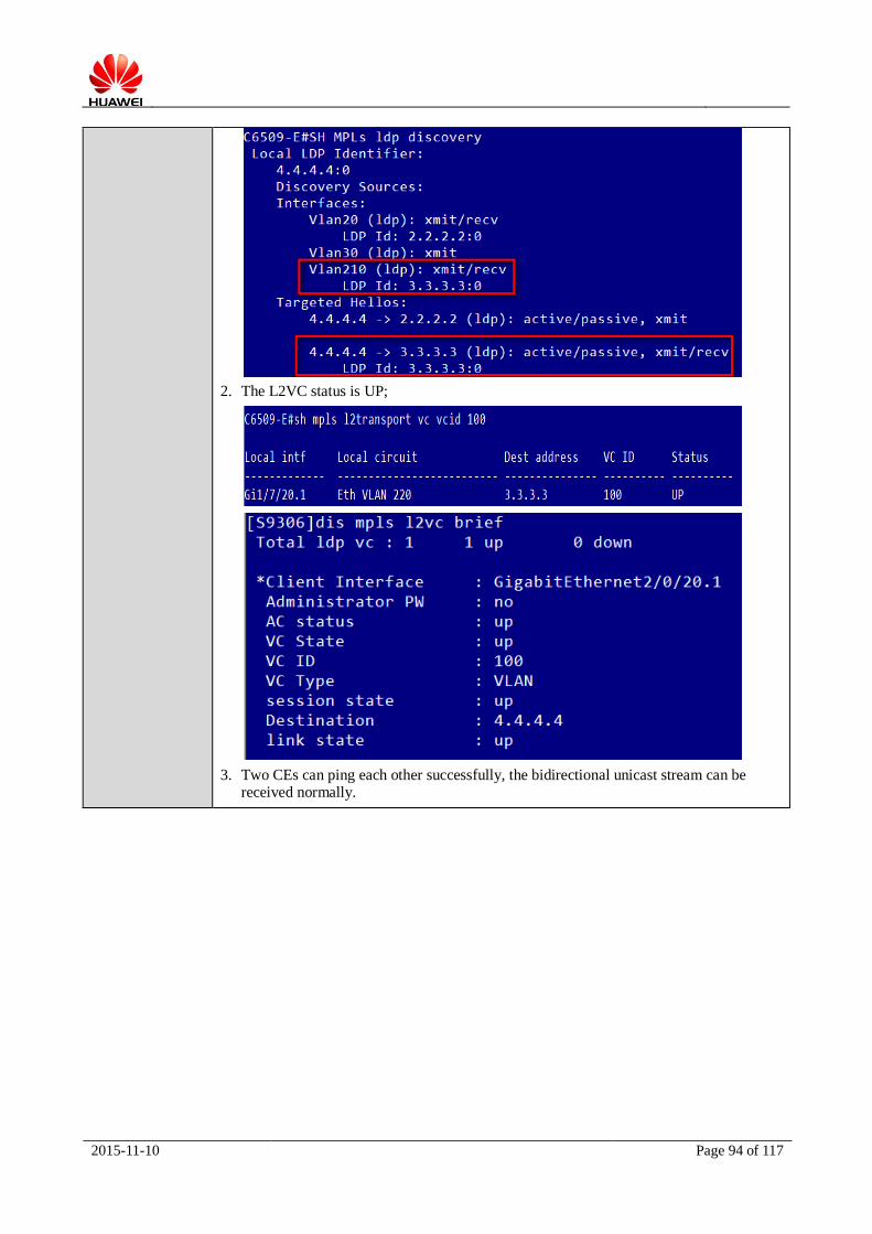
2015-11-10 Page 94 of 117
2. The L2VC status is UP;
3. Two CEs can ping each other successfully, the bidirectional unicast stream can be received normally.
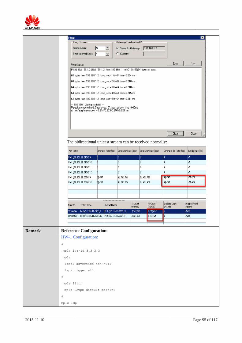
2015-11-10 Page 95 of 117
The bidirectional unicast stream can be received normally:
Remark Reference Configuration:
HW-1 Configuration:
#
mpls lsr-id 3.3.3.3
mpls
label advertise non-null
lsp-trigger all
#
mpls l2vpn
mpls l2vpn default martini
#
mpls ldp
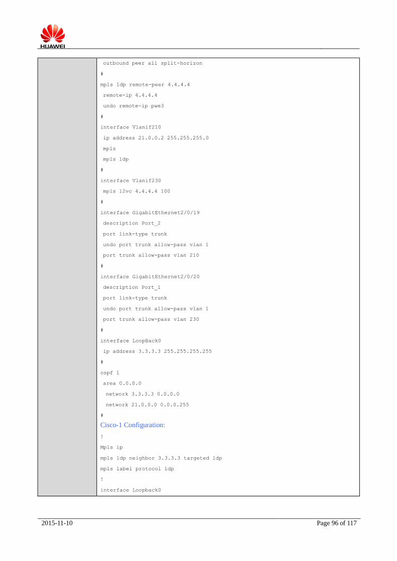
2015-11-10 Page 96 of 117
outbound peer all split-horizon
#
mpls ldp remote-peer 4.4.4.4
remote-ip 4.4.4.4
undo remote-ip pwe3
#
interface Vlanif210
ip address 21.0.0.2 255.255.255.0
mpls
mpls ldp
#
interface Vlanif230
mpls l2vc 4.4.4.4 100
#
interface GigabitEthernet2/0/19
description Port_2
port link-type trunk
undo port trunk allow-pass vlan 1
port trunk allow-pass vlan 210
#
interface GigabitEthernet2/0/20
description Port_1
port link-type trunk
undo port trunk allow-pass vlan 1
port trunk allow-pass vlan 230
#
interface LoopBack0
ip address 3.3.3.3 255.255.255.255
#
ospf 1
area 0.0.0.0
network 3.3.3.3 0.0.0.0
network 21.0.0.0 0.0.0.255
#
Cisco-1 Configuration:
!
Mpls ip
mpls ldp neighbor 3.3.3.3 targeted ldp
mpls label protocol ldp
!
interface Loopback0
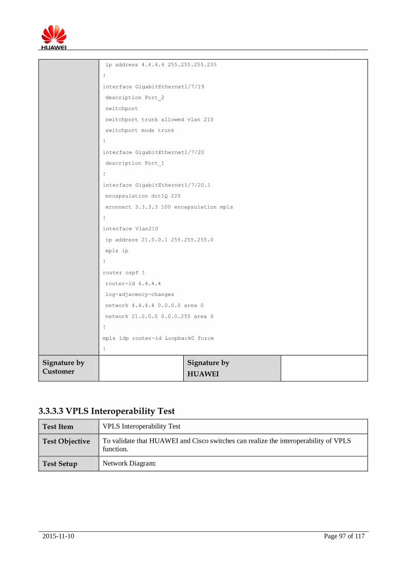
2015-11-10 Page 97 of 117
ip address 4.4.4.4 255.255.255.255
!
interface GigabitEthernet1/7/19
description Port_2
switchport
switchport trunk allowed vlan 210
switchport mode trunk
!
interface GigabitEthernet1/7/20
description Port_1
!
interface GigabitEthernet1/7/20.1
encapsulation dot1Q 220
xconnect 3.3.3.3 100 encapsulation mpls
!
interface Vlan210
ip address 21.0.0.1 255.255.255.0
mpls ip
!
router ospf 1
router-id 4.4.4.4
log-adjacency-changes
network 4.4.4.4 0.0.0.0 area 0
network 21.0.0.0 0.0.0.255 area 0
!
mpls ldp router-id Loopback0 force
!
Signature by Customer
Signature by
HUAWEI
3.3.3.3 VPLS Interoperability Test
Test Item VPLS Interoperability Test
Test Objective To validate that HUAWEI and Cisco switches can realize the interoperability of VPLS
function.
Test Setup Network Diagram:

2015-11-10 Page 98 of 117
Pre-conditions:
1. All device work normally;
2. Establish the test environment according to the above diagram.
Test Procedure 1. Configure IGP protocol on both devices to make IGP routing reachable;
2. Configure MPLS basic function and LDP on both devices, check MPLS forwarding
table, obtain the expected result 1;
3. Enable MPLS L2VPN and configure VPLS VSI function, check VPLS VSI status, obtain the expected result 2;
4. Tester Tport_1 and Tport_2 simulate two hosts as CEs to ping each other, obtain the expected result 3.
Expected Result 1. The MPLS LDP and LSP work normally;
2. The VSI status is UP;
3. Two CEs can ping each other successfully, the bidirectional unicast stream can be received normally.
Actual Result 1. The MPLS LDP and LSP work normally;
The LDP SESSION status:
HW-1 Cisco-1
Port_2 Port_2Port_1 Port_1
Tport_1 Tport_2

2015-11-10 Page 99 of 117
2. The VSI status is UP;
3. Two CEs can ping each other successfully, the bidirectional unicast stream can be
received normally.

2015-11-10 Page 100 of 117
The bidirectional unicast stream can be received normally:
Remark Reference Configuration:
HW-1 Configuration:
#
mpls lsr-id 3.3.3.3
mpls
label advertise non-null
lsp-trigger all

2015-11-10 Page 101 of 117
#
mpls l2vpn
#
mpls ldp
outbound peer all split-horizon
#
mpls ldp remote-peer 4.4.4.4
remote-ip 4.4.4.4
undo remote-ip pwe3
#
vsi wy static
pwsignal ldp
vsi-id 100
peer 4.4.4.4
#
interface Vlanif210
ip address 21.0.0.2 255.255.255.0
mpls
mpls ldp
#
interface Vlanif220
l2 binding vsi wy
#
interface GigabitEthernet2/0/19
description Port_2
port link-type trunk
undo port trunk allow-pass vlan 1
port trunk allow-pass vlan 210
#
interface GigabitEthernet2/0/20
description Port_1
port link-type trunk
undo port trunk allow-pass vlan 1
port trunk allow-pass vlan 220
#
interface LoopBack0
ip address 3.3.3.3 255.255.255.255
#
ospf 1
area 0.0.0.0
network 3.3.3.3 0.0.0.0

2015-11-10 Page 102 of 117
network 21.0.0.0 0.0.0.255
#
Cisco-1 Configuration:
!
Mpls ip
mpls ldp neighbor 3.3.3.3 targeted ldp
mpls label protocol ldp
!
l2 vfi wy manual
vpn id 100
neighbor 3.3.3.3 encapsulation mpls
!
interface Loopback0
ip address 4.4.4.4 255.255.255.255
!
interface GigabitEthernet1/7/19
description Port_2
switchport
switchport trunk allowed vlan 210
switchport mode trunk
!
interface GigabitEthernet1/7/20
description Port_1
switchport
switchport trunk allowed vlan 220
switchport mode trunk
!
interface Vlan210
ip address 21.0.0.1 255.255.255.0
mpls ip
!
interface Vlan220
no ip address
xconnect vfi wy
!
router ospf 1
router-id 4.4.4.4
log-adjacency-changes
network 4.4.4.4 0.0.0.0 area 0
network 21.0.0.0 0.0.0.255 area 0
!
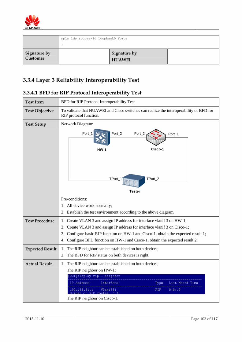
2015-11-10 Page 103 of 117
mpls ldp router-id Loopback0 force
!
Signature by Customer
Signature by
HUAWEI
3.3.4 Layer 3 Reliability Interoperability Test
3.3.4.1 BFD for RIP Protocol Interoperability Test
Test Item BFD for RIP Protocol Interoperability Test
Test Objective To validate that HUAWEI and Cisco switches can realize the interoperability of BFD for
RIP protocol function.
Test Setup Network Diagram:
Port_2
HW-1
Port_2
Cisco-1
TPort_1
Port_1
Tester
Port_1
TPort_2
Pre-conditions:
1. All device work normally;
2. Establish the test environment according to the above diagram.
Test Procedure 1. Create VLAN 3 and assign IP address for interface vlanif 3 on HW-1;
2. Create VLAN 3 and assign IP address for interface vlanif 3 on Cisco-1;
3. Configure basic RIP function on HW-1 and Cisco-1, obtain the expected result 1;
4. Configure BFD function on HW-1 and Cisco-1, obtain the expected result 2.
Expected Result 1. The RIP neighbor can be established on both devices;
2. The BFD for RIP status on both devices is right.
Actual Result 1. The RIP neighbor can be established on both devices;
The RIP neighbor on HW-1:
The RIP neighbor on Cisco-1:

2015-11-10 Page 104 of 117
2. The BFD for RIP status on both devices is right.
The BFD for RIP status on HW-1:
The BFD for RIP status on Cisoc-1:
Remark Reference Configuration:
Cisco-1 Configuration:
!
interface GigabitEthernet3/0/1
ip address 192.168.51.1 255.255.255.0
bfd interval 100 min_rx 100 multiplier 3
!
router rip
version 2
network 2.0.0.0
network 192.168.51.0
neighbor 192.168.51.2 bfd
bfd all-interfaces
!
HW-1 Configuration:

2015-11-10 Page 105 of 117
#
bfd
#
interface LoopBack0
ip address 1.1.51.2 255.255.255.255
#
interface Vlanif51
ip address 192.168.51.2 255.255.255.0
#
interface GigabitEthernet0/1/1
port link-type access
port default vlan 51
#
rip 1
version 2
network 192.168.51.0
network 1.0.0.0
bfd all-interfaces enable
bfd all-interfaces min-tx-interval 100 min-rx-interval 100
#
Signature by Customer
Signature by HUAWEI
3.3.4.2 BFD for OSPF Protocol Interoperability Test
Test Item BFD for OSPF Protocol Interoperability Test
Test Objective To validate that HUAWEI and Cisco switches can realize the interoperability of BFD for
OSPF protocol function.
Test Setup Network Diagram:
Port_1
HW-1
Port_1
Cisco-1
Pre-conditions:
1. All device work normally;
2. Establish the test environment according to the above diagram.
Test Procedure 1. Create VLAN 200 and add Port_1 to VLAN 200 on both devices;
2. Assign IP address for interface vlanif 200 on HW-1 and Cisco-1;
3. Configure Router ID=200.1.1.1, create OSPF process 1 on HW-1 and advertise the

2015-11-10 Page 106 of 117
network route;
4. Configure Router ID=200.1.1.2, create OSPF process 1 on Cisco-1 and advertise the network route;
5. Configure BFD for OSPF on HW-1 and Cisco-1;
6. Check OSPF neighbors on both devices, obtain the expected result 1;
7. Check BFD session status on both devices, obtain the expected result 2.
Expected Result 1. OSPF neighbors can be established on both devices successfully;
2. BFD session status on both devices is right.
Actual Result 1. OSPF neighbors can be established on both devices successfully;
The OSPF neighbor on Cisoc-1:
The OSPF neighbor on HW-1:
2. BFD session status on both devices is right.
The BFD session status on Cisco-1:
The BFD session status on HW-1:

2015-11-10 Page 107 of 117
Remark Reference Configuration:
Cisco-1 Configuration:
!
interface GigabitEthernet1/7/11
description Port_1
ip address 200.1.1.2 255.255.255.0
bfd interval 100 min_rx 100 multiplier 3
!
router ospf 1
router-id 200.1.1.2
network 200.1.1.0 0.0.0.255 area 0
bfd all-interfaces
HW-1 Configuration:
#
interface Vlanif200
ip address 200.1.1.1 255.255.255.0
#
interface GigabitEthernet2/0/45
description Port_1
port link-type access
port default vlan 200
#
ospf 101 router-id 200.1.1.1
bfd all-interfaces enable
bfd all-interfaces min-tx-interval 100 min-rx-interval 100
area 0.0.0.0
network 200.1.1.0 0.0.0.255

2015-11-10 Page 108 of 117
#
Signature by Customer
Signature by HUAWEI
3.3.4.3 BFD for ISIS Protocol Interoperability Test
Test Item BFD for ISIS Protocol Interoperability Test
Test Objective To validate that HUAWEI and Cisco switches can realize the interoperability of BFD for
ISIS protocol function.
Test Setup Network Diagram:
Port_1
HW-1
Port_1
Cisco-1
Pre-conditions:
1. All device work normally;
2. Establish the test environment according to the above diagram.
Test Procedure 1. Create VLAN 200 and add Port_1 to VLAN 200 on both devices;
2. Assign IP address for interface vlanif 200 on HW-1 and Cisco-1;
3. Configure basic ISIS function on HW-1 and Cisco-1;
4. Configure BFD for ISIS function on HW-1 and Cisco-1;
5. Check ISIS neighbors on both devices, obtain the expected result 1;
6. Check BFD session status on both devices, obtain the expected result 2.
Expected Result 1. ISIS neighbors can be established on both devices successfully;
2. BFD session status on both devices is right.
Actual Result 1. ISIS neighbors can be established on both devices successfully;
The ISIS neighbor on Cisco-1:
The ISIS neighbor on HW-1:
2. BFD session status on both devices is right.
The BFD session status on Cisco-1:
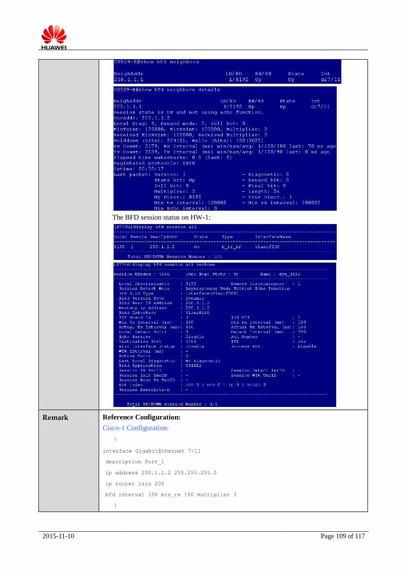
2015-11-10 Page 109 of 117
The BFD session status on HW-1:
Remark Reference Configuration:
Cisco-1 Configuration:
!
interface GigabitEthernet 7/11
description Port_1
ip address 200.1.1.2 255.255.255.0
ip router isis 200
bfd interval 100 min_rx 100 multiplier 3
!
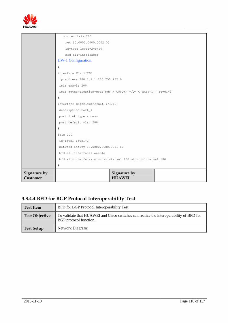
2015-11-10 Page 110 of 117
router isis 200
net 10.0000.0000.0002.00
is-type level-2-only
bfd all-interfaces
HW-1 Configuration:
#
interface Vlanif200
ip address 200.1.1.1 255.255.255.0
isis enable 200
isis authentication-mode md5 N`C55QK<`=/Q=^Q`MAF4<1!! level-2
#
interface GigabitEthernet 4/1/10
description Port_1
port link-type access
port default vlan 200
#
isis 200
is-level level-2
network-entity 10.0000.0000.0001.00
bfd all-interfaces enable
bfd all-interfaces min-tx-interval 100 min-rx-interval 100
#
Signature by Customer
Signature by HUAWEI
3.3.4.4 BFD for BGP Protocol Interoperability Test
Test Item BFD for BGP Protocol Interoperability Test
Test Objective To validate that HUAWEI and Cisco switches can realize the interoperability of BFD for
BGP protocol function.
Test Setup Network Diagram:

2015-11-10 Page 111 of 117
Port_2
HW-1
Port_2
Cisco-1
TPort_1
Port_1
Tester
Port_1
TPort_2
Pre-conditions:
1. All device work normally;
2. Establish the test environment according to the above diagram.
Test Procedure 1. Create VLAN 24 and assign IP address for interface vlanif 3 on HW-1;
2. Create Layer 3 interface and assign IP address for this interface on Cisco-1;
3. Configure basic BGP function on HW-1 and Cisco-1, obtain the expected result 1;
4. Configure BFD function on HW-1 and Cisco-1, obtain the expected result 2.
Expected Result 1. BGP neighbors can be established on both devices successfully;
2. BFD session status on both devices is right.
Actual Result 1. BGP neighbors can be established on both devices successfully;
The BGP neighbor on HW-1:
The BGP neighbor on Cisco-1:
2. BFD session status on both devices is right.
The BFD session status on HW-1:

2015-11-10 Page 112 of 117
The BFD session status on Cisco-1:
Remark Reference Configuration:
Cisco-1 Configuration:
!
interface GigabitEthernet1/7/24
no switchport
ip address 192.168.24.1 255.255.255.0
bfd interval 100 min_rx 100 multiplier 3
!
router bgp 100
no synchronization
bgp log-neighbor-changes
neighbor 192.168.24.2 remote-as 101
neighbor 192.168.24.2 fall-over bfd
no auto-summary
!
HW-1 Configuration:
#
interface Vlanif24
ip address 192.168.24.2 255.255.255.0
#
interface GigabitEthernet4/1/23
port link-type access
port default vlan 24
#
bgp 101
peer 192.168.24.1 as-number 100
peer 192.168.24.1 bfd min-tx-interval 100 min-rx-interval 100
peer 192.168.24.1 bfd enable
#
ipv4-family unicast
undo synchronization
peer 192.168.24.1 enable

2015-11-10 Page 113 of 117
#
Signature by Customer
Signature by HUAWEI
3.3.4.5 VRRP Interoperability Test
Test Item VRRP Interoperability Test
Test Objective To validate that HUAWEI and Cisco switches can realize the interoperability of VRRP
function.
Test Setup Network Diagram:
Port_1Port_2
Cisco-1
Tport_1
Port_1
HW-1
Port_2Port_3
Port_1 Port_2
HW-2
Tester
Port_3
Tport_2
Pre-conditions:
1. All device work normally;
2. Establish the test environment according to the above diagram.
Test Procedure 1. Add Cisco-1 Port_3, HW-1 Port_2, HW-2 Port_1 and Port_2 to the same VLAN;
2. Add Cisco-1 Port_2 and HW-1 Port_1 to the same VLAN, assign IP address for VLAN interface;
3. Add Cisco Port_1 to another VLAN, assign IP address for VLAN interface;
4. Create VRRP group between Cisco-1 and HW-1, configure VRRP priority higher than the default value;
5. Create OSPF protocol between Cisco-1 and HW-1 to make routing reachable;
6. Check VRRP status on Cisco-1 and HW-1, obtain the expected result 1;
7. Tester send bidirectional stream, obtain the expected result 2;
8. Disconnect HW-1 Port_2, check VRRP status on Cisco-1, obtain the expected result 3;
9. Connect HW-1 Port_2, check VRRP status on Cisco-1 and HW-1, obtain the expected
result 4.

2015-11-10 Page 114 of 117
Expected Result 1. Cisco-1 is VRRP backup, HW-1 is VRRP master;
2. The stream can be forwarded normally, there is no packet loss;
3. Cisco-1 is VRRP master, VRRP shift successfully, the packet loss is under the expectation;
4. HW-1 is VRRP master, Cisco-1 is VRRP backup, the packet loss is under expectation.
Actual Result 1. Cisco-1 is VRRP backup, HW-1 is VRRP master;
2. The stream can be forwarded normally, there is no packet loss;
3. Cisco-1 is VRRP master, VRRP shift successfully, the packet loss is under the expectation;
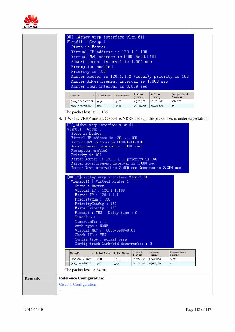
2015-11-10 Page 115 of 117
The packet loss is: 26.18S
4. HW-1 is VRRP master, Cisco-1 is VRRP backup, the packet loss is under expectation.
The packet loss is: 34 ms
Remark Reference Configuration:
Cisco-1 Configuration:
!

2015-11-10 Page 116 of 117
vlan 610-612
!
interface GigabitEthernet1/0/3
description Port_2
switchport trunk encapsulation dot1q
switchport trunk allowed vlan 610
switchport mode trunk
!
interface GigabitEthernet1/0/4
description Port_3
switchport trunk encapsulation dot1q
switchport trunk allowed vlan 611
switchport mode trunk
!
interface GigabitEthernet1/0/7
description Port_1
switchport trunk encapsulation dot1q
switchport trunk allowed vlan 612
switchport mode trunk
!
interface Vlan610
ip address 110.1.1.2 255.255.255.0
!
interface Vlan611
ip address 120.1.1.2 255.255.255.0
vrrp 1 ip 120.1.1.100 //the default priority value is 100
!
interface Vlan612
ip address 130.1.1.1 255.255.255.0
!
router ospf 100
router-id 120.1.1.2
network 110.1.1.0 0.0.0.255 area 0
network 120.1.1.0 0.0.0.255 area 0
network 130.1.1.0 0.0.0.255 area 0
!
HW-1 Configuration:
#
vlan batch 610 to 611
#
interface Vlanif610

2015-11-10 Page 117 of 117
ip address 110.1.1.1 255.255.255.0
#
interface Vlanif611
ip address 120.1.1.1 255.255.255.0
vrrp vrid 1 virtual-ip 120.1.1.100
vrrp vrid 1 priority 150
#
interface GigabitEthernet0/0/1
description Port_1
port link-type trunk
port trunk allow-pass vlan 610
#
interface GigabitEthernet0/0/3
description Port_2
port link-type trunk
port trunk allow-pass vlan 611
#
ospf 100
area 0.0.0.0
network 120.1.1.0 0.0.0.255
network 110.1.1.0 0.0.0.255
#
HW-2 Configuration:
#
interface GigabitEthernet0/0/1
description Port_1
port link-type trunk
port trunk allow-pass vlan 611
#
interface GigabitEthernet0/0/2
description Port_2
port link-type trunk
port trunk allow-pass vlan 611
#
interface GigabitEthernet0/0/3
description Port_3
port link-type trunk
port trunk allow-pass vlan 611
#
Signature by Customer
Signature by HUAWEI


![Huawei CloudEngine Series Switch V100R002 Security …ASE]CloudEngine... · Huawei CloudEngine Series Switch V100R002 Security Target Huawei Technologies Co., Ltd. Classification:](https://static.fdocuments.in/doc/165x107/5b1569ba7f8b9afb0a8c2054/huawei-cloudengine-series-switch-v100r002-security-asecloudengine-huawei.jpg)