3 g huawei ran resource monitoring and management recommended
description

SingleRAN
Monitoring ManagementFeature Parameter Description
Copyright © Huawei Technologies Co., Ltd. 2012. All rights reserved.
No part of this document may be reproduced or transmitted in any form or by any means without prior written consent of HuaweiTechnologies Co., Ltd.
Trademarks and Permissions
and other Huawei trademarks are the property of Huawei Technologies Co., Ltd. All other trademarks and trade namesmentioned in this document are the property of their respective holders.
Notice
The purchased products, services and features are stipulated by the commercial contract made between Huawei and the customer. Allor partial products, services and features described in this document may not be within the purchased scope or the usage scope.Unless otherwise agreed by the contract, all statements, information, and recommendations in this document are provided "AS IS"without warranties, guarantees or representations of any kind, either express or implied.
The information in this document is subject to change without notice. Every effort has been made in the preparation of this document toensure accuracy of the contents, but all statements, information, and recommendations in this document do not constitute a warranty ofany kind, express or implied.

Contents1 Introduction
1.1 Scope1.2 Intended Audience1.3 Change History
2 Overview of Monitoring Management2.1 Monitoring Managers
2.1.1 BBU Monitoring Ports2.1.2 CCU Monitoring Ports2.1.3 RRU Monitoring Ports
2.2 Monitoring Principles2.2.1 Singlemode/Dualmode Base Station2.2.2 Triplemode Base Station
2.3 Customized Alarms
3 Engineering Guidelines4 Engineering Guidelines (UMTS or LTE)
4.1 When to Use Monitoring Management4.2 Information to Be Collected4.3 Network Planning4.4 Feature Deployment
4.4.1 Deployment Procedure4.4.2 Deployment Requirements4.4.3 Data Preparation4.4.4 Precautions4.4.5 Hardware Installation4.4.6 Feature Activation/Initial Configuration4.4.7 Commissioning4.4.8 Activation Verification4.4.9 Reconfiguration4.4.10 Deactivation
4.5 Optimization4.6 Troubleshooting
5 Engineering Guidelines (GSM)5.1 When to Use Monitoring Management5.2 Information to Be Collected5.3 Network Planning5.4 Feature Deployment
5.4.1 Deployment Procedure5.4.2 Deployment Requirements5.4.3 Data Preparation5.4.4 Precautions5.4.5 Hardware Installation5.4.6 Feature Activation/Initial Configuration5.4.7 Commissioning5.4.8 Activation Verification5.4.9 Reconfiguration5.4.10 Deactivation
5.5 Optimization5.6 Troubleshooting
6 Engineering Guidelines (Dual Modes)6.1 Precautions for OneSided Configuration6.2 Precautions for ModebyMode Configuration
7 Reference Documents
1 Introduction1.1 Scope

This document describes the principles and engineering guidelines for the 3900 series base station monitoring management feature.The 3900 series base station monitoring management feature involves two basic LTE features, LBFD004012 Environment Monitoringand TDLBFD004012 Environment Monitoring. In GBSS, RAN, and SRAN, the 3900 series base station monitoring management is abasic feature and involves no feature ID.
This document is applicable to the following 3900 series base stations:
BTS3900 (Ver.B), BTS3900 (Ver.C), and BTS3900 (Ver.D)BTS3900L (Ver.B), BTS3900L (Ver.C), and BTS3900L (Ver.D)BTS3900A (Ver.B), BTS3900A (Ver.C), and BTS3900A (Ver.D)BTS3900AL (Ver.A)DBS3900BTS3900C, BTS3900C (Ver.B), and BTS3900C (Ver.C)
Any managed objects (MOs), parameters, alarms, or counters described in this document correspond to the software release deliveredwith this document. In the event of updates, the updates will be described in the product documentation delivered with the latestsoftware release.
1.2 Intended AudienceThis document is intended for:
Personnel who need to understand monitoring managementField engineers
1.3 Change HistoryThis section provides information about the changes in different document versions.
There are two types of changes, which are defined as follows:
Feature change: refers to a change in the monitoring management feature of a specific product version.Editorial change: refers to a change in wording or the addition of information that was not described in the earlier version.
Document IssuesThe document issues are as follows:
03 (20120915)02 (20120723)01 (20120425)Draft B (20120310)Draft A (20120110)
03 (20120915)This is the third commercial release.
Compared with issue 02 (20120723), this issue incorporates the changes described in the following table.
ChangeType
Change Description Parameter Change
Featurechange
Added the following information:Monitoring principles of the BTS3900 (Ver.D)in "BTS3900" in section 2.2.1 "Singlemode/Dualmode Base Station."Monitoring principles of the BTS3900L(Ver.D) in "BTS3900L" in section 2.2.1"Singlemode/Dualmode Base Station."Monitoring principles of the BTS3900A(Ver.D) in "BTS3900A" in section 2.2.1"Singlemode/Dualmode Base Station."Monitoring principles of the DBS3900 housedin the APM30H (Ver.D) or TMC11H (Ver.D)in "DBS3900" in section 2.2.1 "Singlemode/Dualmode Base Station."
None
Editorialchange
None None
02 (20120723)This is the second official release.
Compared with issue 01 (20120425), this issue incorporates the changes described in the following table.
ChangeType
Change Description Parameter Change

Featurechange
Added the low noise mode for the fan. Added the TCMODE parameterfor the FMU in GSM, UMTS, andLTE modes.
Editorialchange
None None
01 (20120425)This is the first official release.
Compared with draft B (20120310), this issue does not incorporate any change.
Draft B (20120310)This is a draft.
Compared with draft A (20120110), this issue incorporates the changes described in the following table.
ChangeType
Change Description Parameter Change
Featurechange
The parameter value GS_DISABLE(DoorSensor Disabled) of SBAF in CCU is deleted.
None
Editorialchange
Added chapter 3 "Engineering Guidelines." None
Optimized the precautions of chapter 6"Engineering Guidelines (Dual Modes)."
None
Draft A (20120110)This is a draft.
This document is the first release for SRAN7.0, GBSS14.0, and RAN14.0.
For eRAN3.0, this document is modified based on issue 03 (20111224) of eRAN2.2. Compared with issue 03 (20111224) ofeRAN2.2, this issue incorporates the changes described in the following table.
ChangeType
Change Description Parameter Change
Featurechange
Added the following BTS3900ALrelatedinformation:Monitoring principles of the BTS3900AL insection 2.2.1 "Singlemode/Dualmode BaseStation."CCU information in section 2.1.2 "CCUMonitoring Ports."
Added the CCU MO.Added the following CCUrelatedparameters:DCFCCNCS
Added the monitoring principles of theDBS3900 housed in the TP48600A cabinet insection 2.2.1 "Singlemode/Dualmode BaseStation."
None
Editorialchange
Added the monitoring principles andengineering guidelines for the NodeB, BTS,and MBTS.
Added GSM and UMTSconfiguration parameters.
Added section 2.2 "Monitoring Principles." None
Added the reference for configuring themonitoring function in section 4.4.3 "DataPreparation."
None
2 Overview of Monitoring ManagementThe monitoring system is an important component of a base station. The system monitors the power supply, fans, and environment inthe cabinet. When a fault is detected, the system reports an alarm. In addition, the monitoring system collects alarm signals fromoutside the cabinet to monitor the environment and specified devices, such as diesel generators and equipment room door statuscontrol devices.
2.1 Monitoring ManagersThe monitoring managers include the baseband unit (BBU), cabinet control unit (CCU), and radio remote unit (RRU). The monitoreddevices in the cabinet communicate with the monitoring managers through an RS485 bus.
The BBU is the monitoring management center for most base stations. Both internal and external alarms are directly reported to the

BBU and then forwarded to the alarm console.
When a base station has many devices to be monitored in the cabinets, the BBU monitoring ports cannot meet the monitoringrequirements. In this situation, the CCU of each cabinet monitors devices housed in the cabinet. The CCUs are cascaded and one CCUreports alarms to the BBU. Currently, only the BTS3900AL cabinet, TP48600AH17B1 (TP48600A for short) cabinet for DBS3900, andIBBS700D/IBBS700T cabinet use the CCUs to implement monitoring management.
For some DBS3900s, alarms are managed by the RRU because the RRU is installed far away from the BBU. The RRU reports alarmsto the BBU through a common public radio interface (CPRI) fiber optic cable and the BBU then forwards the alarms to the alarmconsole. This scenario is called remote monitoring.
2.1.1 BBU Monitoring PortsIn a BBU, the universal power and environment interface unit (UPEU) and universal environment interface unit (UEIU) boards providemonitoring ports. Each board provides two Boolean input ports and two RS485 input ports. Each Boolean input port supports fourBoolean inputs.
When a BBU is configured with one UPEU, the BBU provides eight Boolean inputs and two RS485 inputs.When a BBU is configured with two UPEUs or with one UPEU and one UEIU, the BBU provides 16 Boolean inputs and four RS485inputs. The two MON0 ports on different UPEUs or on the UPEU and UEIU are interconnected through RS485 bus 0, and the twoMON1 ports are interconnected through RS485 bus 1.
Figure 21 shows the monitoring ports on the UPEU and UEIU.
Figure 21 Monitoring ports on the UPEU and UEIU
Table 21 describes the monitoring ports on the UPEU and UEIU.
Table 21 Monitoring ports on the UPEU and UEIU
Board Label Connector Description
UPEU EXTALM0 RJ45 For Boolean inputs 0 to 3
EXTALM1 RJ45 For Boolean inputs 4 to 7
MON0 RJ45 RS485 input port 0
MON1 RJ45 RS485 input port 1
UEIU EXTALM0 RJ45 For Boolean inputs 0 to 3
EXTALM1 RJ45 For Boolean inputs 4 to 7
MON0 RJ45 RS485 input port 0
MON1 RJ45 RS485 input port 1
2.1.2 CCU Monitoring PortsThe CCU monitors the environment and devices in the cabinet. Figure 22 shows the monitoring ports on the CCU.
Figure 22 CCU monitoring ports
Table 22 describes the monitoring ports on the CCU. For details about the functions of the other ports on the CCU, see section "CCU"in BTS3900AL (Ver.A) Hardware Description.
Table 22 CCU monitoring ports
Label Connector Description
FE_L, FE_R RJ45 For CCU cascading
D_COM0 to D_COM7 RJ45 Downlink RS485 ports 0 to 7 forcommunicating with boards in the cabinet
U_COM0 to U_COM2 RJ45 Uplink RS485 ports 0 to 2 for communicatingwith upperlevel boards
TEM 4pin wire terminal block Reserved for the temperature sensor
SMOKE 2pin wire terminal block For the smoke sensor that is optionallyconfigured
GATE 2pin bare wire terminalblock
For the door status sensor that is configuredby default
IN0 2pin bare wire terminalblock
Reserved for two Boolean inputs
IN1 2pin bare wire terminalblock
For the AC surge protector that is configuredby default
LAMP 2pin bare wire terminalblock
For the cabinet lamp that is configured bydefault
2.1.3 RRU Monitoring PortsRRU monitoring ports vary with RRU models. Some RRUs provide one monitoring port which supports two or four Boolean inputs andone RS485 input. Some RRUs do not provide any monitoring port.
For details, see section "RRU Ports" in the RRUspecific hardware description.
2.2 Monitoring Principles2.2.1 Singlemode/Dualmode Base StationThe monitoring boards of a base station report monitoring information. For example, the fan monitoring unit (FMU) reports fanmonitoring information, the power monitoring unit (PMU) reports power supply monitoring information, and the environment monitoringunit (EMU) or environment monitoring unit type A (EMUA) reports environment monitoring alarms and customized alarms. All themonitoring signals are transmitted to the BBU, CCU, or RRU monitoring ports through an RS485 bus. This section describes theconnections between the monitoring boards and the BBU, CCU, and RRU.
For details about how to connect the monitoring signal cables of the boards to relevant ports, see sections "Monitoring Principles of the Cabinet" and"Monitoring Signal Cable Connections" in the base stationspecific hardware description.
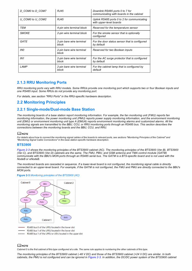
BTS3900Figure 23 shows the monitoring principles of the BTS3900 cabinet (AC). The monitoring principles of the BTS3900 (Ver.B), BTS3900(Ver.C), and BTS3900 (Ver.D) cabinets are the same. The FMU, PMU, and GSM antenna and TMA control module (GATM)communicate with the BBU's MON ports through an RS485 serial bus. The GATM is a BTSspecific board and is not used with theNodeB or eNodeB.
The monitored boards are cascaded in sequence. If a lowerlevel board is not configured, the monitoring signal cable is directlyconnected to an upperlevel board. For example, if the GATM is not configured, the FMU and PMU are directly connected to the BBU'sMON ports.
Figure 23 Monitoring principles of the BTS3900 (AC)
Cabinet 0 is the first cabinet of this type configured at a site. The same rule applies to numbering the other cabinets of this type.
The monitoring principles of the BTS3900 cabinet (48 V DC) and those of the BTS3900 cabinet (+24 V DC) are similar. In bothcabinets, the PMU is not configured and can be ignored in Figure 23. In addition, the DC/DC power system of the BTS3900 cabinet

(+24 V DC) needs to be connected to the BBU's EXT_ALM port to report Boolean signals.
BTS3900LFigure 24 shows the monitoring principles of the BTS3900L cabinet (48 V DC). The monitoring principles of the BTS3900L (Ver.B),BTS3900L (Ver.C), and BTS3900L (Ver.D) cabinets are the same. The FMU and GATM communicate with the BBU's MON portsthrough an RS485 serial bus. The GATM is a BTSspecific board and is not used with the NodeB or eNodeB.
The monitored boards are cascaded in sequence. If a lowerlevel board is not configured, the monitoring signal cable is directlyconnected to an upperlevel board. For example, if the GATM is not configured, the FMU is directly connected to the BBU's MON port.
In Figure 24, FMU0 refers to the FMU in the lowerlevel subrack and FMU1 refers to the FMU in the upperlevel subrack in theBTS3900L cabinet. Cascade them following the sequence shown in Figure 24.
Figure 24 Monitoring principles of the BTS3900L
BTS3900AFigure 25 and Figure 26 show the monitoring principles of the BTS3900A cabinet (AC) and BTS3900A cabinet (DC), respectively. Thecentral monitoring unit type A (CMUA)/central monitoring unit type E (CMUE)/central monitoring unit type EA (CMUEA), PMU, GATM,and EMU communicate with the BBU's MON ports through an RS485 serial bus. The GATM is a BTSspecific board and is not usedwith the NodeB or eNodeB.
The monitored boards are cascaded in sequence. If an upperlevel board is not configured, the monitoring signal cable is directlyconnected to a lowerlevel board. For example, if the TMC cabinet is not configured, ignore the connections related to TMC cabinetconnections shown in Figure 25 and Figure 26. The CMUE in cabinet RFC0 is directly connected to the CMUE in cabinet RFC1.
The monitoring principles of the BTS3900A (Ver.B) cabinet are the same as those of the BTS3900A (Ver.C) cabinet, except that theCMUE is replaced with the CMUA.
The monitoring principles of the BTS3900A (Ver.D) cabinet are the same as those of the BTS3900A (Ver.C) cabinet, except that noHert power monitoring interface unit (HPMI) is configured and the CMUE is replaced with the CMUEA. The HPMI does not monitorsignals but transfers signals for the PMU. Figure 25 and Figure 26 show the monitoring principles only for the BTS3900A (Ver.C)cabinet.
Two battery backup cabinets (BBCs) are cascaded in sequence and cannot be connected to the same PMU. For example, if BBC0connects to the PMU's COM_485 port, BBC1 connects to the CMUE's COM_OUT port in BBC0 and cannot be connected to the otherRS485 ports on the PMU.
Figure 25 Monitoring principles of the BTS3900A (AC)
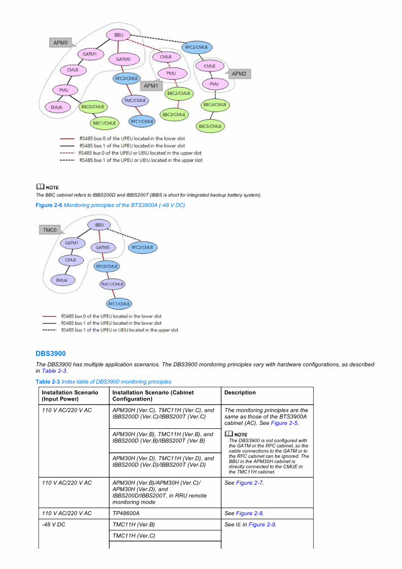
The BBC cabinet refers to IBBS200D and IBBS200T (IBBS is short for integrated backup battery system).
Figure 26 Monitoring principles of the BTS3900A (48 V DC)
DBS3900The DBS3900 has multiple application scenarios. The DBS3900 monitoring principles vary with hardware configurations, as describedin Table 23.
Table 23 Index table of DBS3900 monitoring principles
Installation Scenario(Input Power)
Installation Scenario (CabinetConfiguration)
Description
110 V AC/220 V AC APM30H (Ver.C), TMC11H (Ver.C), andIBBS200D (Ver.C)/IBBS200T (Ver.C)
The monitoring principles are thesame as those of the BTS3900Acabinet (AC). See Figure 25.
The DBS3900 is not configured withthe GATM or the RFC cabinet, so thecable connections to the GATM or tothe RFC cabinet can be ignored. TheBBU in the APM30H cabinet isdirectly connected to the CMUE inthe TMC11H cabinet.
APM30H (Ver.B), TMC11H (Ver.B), andIBBS200D (Ver.B)/IBBS200T (Ver.B)
APM30H (Ver.D), TMC11H (Ver.D), andIBBS200D (Ver.D)/IBBS200T (Ver.D)
110 V AC/220 V AC APM30H (Ver.B)/APM30H (Ver.C)/APM30H (Ver.D), andIBBS200D/IBBS200T, in RRU remotemonitoring mode
See Figure 27.
110 V AC/220 V AC TP48600A See Figure 28.
48 V DC TMC11H (Ver.B) See Πin Figure 29.
TMC11H (Ver.C)

APM30H (Ver.D)
+24 V DC APM30H (Ver.B) See in Figure 29.
110 V AC/220 V AC Outdoor mini box (OMB) See Ž in Figure 29.
48 V DC OMB See Ž in Figure 29. Themonitoring principles are similarto those of the OMB (AC) exceptthat the PMU is not used for theOMB (DC).
110 V AC/220 V AC OMB (Ver.C) See Ž in Figure 29.
48 V DC OMB (Ver.C) See Ž in Figure 29. Themonitoring principles are similarto those of the OMB (AC) exceptthat the PMU is not used for theOMB (DC).
110 V AC/220 V AC Indoor centralized rack (ICR): BBU andPMU are installed in the upper and lowerracks respectively in the indoor mini box(IMB03)
See in Figure 29.
+24 V DC ICR: BBU is installed in the IMB03 See in Figure 29.
110 V AC/220 V AC IMB03 See in Figure 29.
48 V DC IMB03 Monitoring is not required.
For the APM/TMC series cabinets used in the DBS3900 in RRU remote monitoring mode, the monitoring principles of the Ver.Bcabinets are the same as those of the Ver.C cabinets, except that the CMUE is replaced with the CMUA. In addition, the monitoringprinciples of the Ver.D cabinets are the same as those of the Ver.C cabinets, except that the CMUE is replaced with the CMUEA. Figure27 shows the monitoring principles of the Ver.C cabinets.
The monitoring principles of the OMB (Ver.C) cabinet are the same as those of the OMB cabinet, except that the HEUA is replaced withthe HEUB. Figure 29 shows the monitoring principles of the OMB cabinet.
Figure 27 Remote monitoring principles
Figure 28 Monitoring principles of the DBS3900 housed in TP48600A
Figure 29 Monitoring principles of the DBS3900 housed in other cabinets

BTS3900ALThe BTS3900AL uses CCUs to monitor boards in its cabinets, as shown in Figure 210. The CMUF, FAU, and PMU communicate withthe CCUs' downlink RS485 ports through an RS485 serial bus. One CCU then reports alarms to the BBU through the CCU's uplinkRS485 port. The GATM is a BTSspecific board and is not used with the NodeB or eNodeB.
If the TMC and IBBS700D/IBBS700T cabinets are not configured, ignore the boards in these cabinets.
Figure 210 Monitoring principles of the BTS3900AL in single mode or dual mode
BTS3900CThe monitoring principles of the BTS3900C are the same as those of the DBS3900 housed in the OMB. The monitoring principles of theBTS3900C (Ver.C) are the same as those of the DBS3900 housed in the OMB (Ver.C). For details, see Table 23.
2.2.2 Triplemode Base StationTwo BBUs are required for the base station evolution from single or dual mode to triple mode or when a triplemode base station isdeployed.
All the monitored devices of the BTS3900, BTS3900L, BTS3900A, and DBS3900 (not housed in TP48600A) are connected only toBBU0 (hub BBU). The extension BBU does not provide monitoring management.Figure 211 shows the monitoring principles of the BTS3900AL where two BBUs are configured. BBU0 and BBU1 are connected tothe CCU's uplink RS485 ports U_COM0 and U_COM1, respectively. The monitoring principles of the DBS3900 housed in TP48600Aare similar.
Figure 211 Monitoring principles of the BTS3900AL in triple mode

2.3 Customized AlarmsYou can customize alarms to monitor external devices.
To implement Boolean signal input, connect the monitored devices to the BBU, RRU, EMU, or EMUA that has Boolean alarm signalinput ports.To implement analog signal input, connect the monitored devices to the EMU or EMUA that has analog alarm signal input ports.To implement Boolean signal output, connect the monitored devices to the EMU or EMUA that has Boolean signal output ports.
Ambient alarms are common customized alarms. They are generated after sensors installed outdoors or in the equipment room receivealarm signals. Some base stations have sensors that are preinstalled before delivery, as shown in Table 24.
Table 24 Sensors preinstalled on base stations before delivery
Base Station Type Cabinet Preinstalled Sensor
BTS3900/BTS3900L BTS3900/BTS3900L None
BTS3900A/DBS3900 (1)
(2)APM30H (Ver.B)/ APM30H(Ver.C)
Door status sensor, which isconnected to the HPMI's GATEport.
APM30H (Ver.D) Door status sensor, which isconnected to the PMU's GATEport.
RFC Door status sensor, which isconnected to the CMUA's (3),CMUE's, or CMUEA's GATEport.Temperature sensor, which isconnected to the CMUA's,CMUE's, or CMUEA's TEM port.
TMC11H Door status sensor, which isconnected to the CMUA's(4),CMUE's, or CMUEA's GATE port.
IBBS200D/IBBS200T Door status sensor, which isconnected to the CMUA's,CMUE's, or CMUEA's GATEport.Temperature sensor for thebattery, which is connected tothe CMUA's, CMUE's, orCMUEA's TEM_BAT port.
BTS3900AL (5) BTS3900AL(AC)/BTS3900AL(DC) Door status sensor, which isconnected to the CCU's GATEport.
Return air temperature sensor forHEX inner circulation, which isconnected to the CMUF's TEM0port.

Intake air temperature sensor forthe RF compartment, which isconnected to the FAU's TEM0port.
Supply air temperature sensor forHEX inner circulation, which isconnected to the CMUF'sTEMP1 port.
TMC11H Door status sensor, which isconnected to the CMUA's,CMUE's, or CMUEA's GATE port.
BTS3900C BTS3900C None
The DBS3900 housed in the OMB or IMB does not have preinstalled sensors.The DBS3900 may also be configured with the TP48600A cabinet. For details about the sensor configuration in this cabinet, see TP48600AH17B1 User
Manual.In the BTS3900A (Ver.B), the sensors are connected to the CMUA. In the BTS3900A (Ver.C), the sensors are connected to the CMUE. In the BTS3900A
(Ver.D), the sensors are connected to the CMUEA.In the TMC11H (Ver.B), the sensors are connected to the CMUA. In the TMC11H (Ver.C), the sensors are connected to the CMUE. In the TMC11H (Ver.D),
the sensors are connected to the CMUEA.The BTS3900AL may also be configured with the TP48600A and IBBS700D/IBBS700T cabinets. For details about the sensor configuration in these
cabinets, see TP48600AH17B1 User Manual and IBBS700D & IBBS700T User Manual.
3 Engineering GuidelinesIn a multimode base station, deploy the Monitoring Management feature either in single or dual modes.
For the method of deploying this feature in singlemode, see chapter 4 "Engineering Guidelines (UMTS or LTE)" and chapter 5"Engineering Guidelines (GSM)."For the method of deploying this feature in dualmode, see chapter 6 "Engineering Guidelines (Dual Modes)."
4 Engineering Guidelines (UMTS or LTE)4.1 When to Use Monitoring ManagementIt is recommended that the monitoring management feature be enabled when you intend to monitor power and fan units in a NodeB oreNodeB. If auxiliary devices capable of monitoring functions are configured for a NodeB or eNodeB, it is recommended that thecustomized alarm function be enabled.
4.2 Information to Be CollectedSoftware configuration varies according to hardware configuration and cable connections between monitoring boards. Before youconfigure software, collect information about the following devices based on the hardware configuration or hardware configuration plan:
Planned or installed boards related to monitoring
Table 41 lists the boards that need to be configured for different types of NodeBs and eNodeBs in different scenarios.
Devices that manage boards
Board managers include BBU, CCU, and RRU. Collect their respective information according to the hardware connections onsite.
The logical names in Table 41 are the names of devices displayed on the configuration tool interface.
Table 41 Boards required for different types of NodeBs and eNodeBs in different scenarios
NodeB and eNodeBType
Usage Scenario Required Board
Board LogicalName
BTS3900 (Ver.B)BTS3900 (Ver.C)BTS3900 (Ver.D)BTS3900L (Ver.B)BTS3900L (Ver.C)BTS3900L (Ver.D)
48 V DC power input FMU FMU
+24 V DC power input FMU FMU
110 V AC/220 V AC power input FMU FMU
PMU PMU
BTS3900A (Ver.B) APM30H (Ver.B) cabinet PMU PMU
CMUA TCU
RFC (Ver.B) cabinet CMUA FMU
(1) (2)
(3)
(4)
(5)

TMC11H (Ver.B) cabinet CMUA TCU
IBBS200D (Ver.B)/IBBS200T (Ver.B)cabinet
CMUA TCU
BTS3900A (Ver.C) APM30H (Ver.C) cabinet PMU PMU
CMUE TCU
RFC (Ver.C) cabinet CMUE FMU
TMC11H (Ver.C) cabinet CMUE TCU
IBBS200D (Ver.C)/IBBS200T (Ver.C)cabinet
CMUE TCU
BTS3900A (Ver.D) APM30H (Ver.D) cabinet PMU 11A PMU
CMUEA TCU
RFC (Ver.D) cabinet CMUEA FMU
TMC11H (Ver.D) cabinet CMUEA TCU
IBBS200D (Ver.D)/IBBS200T (Ver.D)cabinet
CMUEA TCU
DBS3900 APM30H (Ver.B) cabinet PMU PMU
CMUA TCU
TMC11H (Ver.B) cabinet CMUA TCU
IBBS200D (Ver.B)/IBBS200T (Ver.B)cabinet
CMUA TCU
IBBS700D or IBBS700T cabinet CCU CCU
CMUF TCU
HAU TCU
APM30H (Ver.C) cabinet PMU PMU
CMUA TCU
TMC11H (Ver.C) cabinet CMUE TCU
IBBS200D (Ver.C)/IBBS200T (Ver.C)cabinet
CMUE TCU
APM30H (Ver.D) cabinet PMU 11A PMU
CMUEA TCU
TMC11H (Ver.D) cabinet CMUEA TCU
IBBS200D (Ver.D)/IBBS200T (Ver.D)cabinet
CMUEA TCU
OMB cabinet HEUA TCU
PMU PMU
OMB (Ver.C) cabinet HEUB TCU
PMU 11A PMU
IMB cabinet PMU PMU
IMB cabinet (in ICR scenario) PMU PMU
TP48600A cabinet CCU CCU
PMU PMU
CMUF TCU
HAU TCU
BTS3900AL (Ver.A) BTS3900AL (AC) cabinet CCU CCU
CMUF TCU
PMU PMU
FAU FMU
HAU TCU
BTS3900AL (DC) cabinet CCU CCU
CMUF TCU

FAU FMU
HAU TCU
TMC11H (Ver.C) cabinet CMUE TCU
IBBS700D or IBBS700T cabinet CCU CCU
CMUF TCU
HAU TCU
BTS3900C/BTS3900C(Ver.B)
DC power input HEUA TCU
AC power input PMU PMU
HEUA TCU
BTS3900C (Ver.C) DC power input HEUB TCU
AC power input PMU 11A PMU
HEUB TCU
The full names of the boards listed in Table 41 are as follows:FMU: fan monitoring unitPMU: power monitoring unitPMU 11A: power monitoring unitCMUA: central monitoring unit type ATCU: temperature control unitCCU: cabinet control unitHEUA: heat exchange unit type AHEUB: heat exchange unit type BCMUE: central monitoring unit type ECMUF: central monitoring unit type FCMUEA: central monitoring unit type EAFAU: fan assembly unitHAU: heater assembly unit
The monitoring boards required by the TP48600A cabinet do not need to be configured when other cabinets are configured for a NodeB or eNodeB.
4.3 Network PlanningRF PlanningN/A
Network TopologyN/A
Hardware Planning
Configuration Planning for Monitoring Devices
The EMU or EMUA may be required for configuring customized alarms on NodeBs and eNodeBs. Table 42 describes the hardwareplanning for customized alarm configuration. The logical names in Table 42 are the names of devices displayed on the configurationtool interface.
Table 42 Hardware planning for customized alarm configuration
NodeB andeNodeB Type
Usage Scenario Required Device
Device Name Logical Name
BTS3900 (Ver.B)BTS3900 (Ver.C)BTS3900 (Ver.D)BTS3900L (Ver.B)BTS3900L (Ver.C)BTS3900L (Ver.D)
1 to 16 Boolean alarm inputs NA(1) NA
17 to 32 Boolean alarm inputs EMU(2) EMU
1 to 6 Boolean alarm outputs EMU EMU
RRU remote monitoring NA(3) NA
1 to 4 analog alarm inputs EMU EMU
BTS3900A (Ver.B)BTS3900A (Ver.C)BTS3900A (Ver.D)DBS3900BTS3900AL (Ver.A)
1 to 16 Boolean alarm inputs NA(1) NA
17 to 32 Boolean alarm inputs EMUA(2) EMU
1 to 4 remote Boolean alarm inputs NA(3) NA
1 to 6 Boolean alarm outputs EMUA EMU
(1) (2) (3) (4) (5) (6) (7) (8) (9) (10) (11) (12) (13)

1 to 4 analog alarm inputs EMUA EMU
BTS3900C (4)
BTS3900C (Ver.B)(4)
BTS3900C (Ver.C)(4)
1 to 16 Boolean alarm inputs NA(1) NA
(1) When defining 1 to 16 Boolean inputs, you can install one UPEU and one UEIU in a BBU. It is recommended that you not configure customized alarms ofthe Boolean ports on the FMU, PMU, CMUA, CMUE, CMUF, or CCU. If you want to use them, contact Huawei technical support.
(2) The EMU or EMUA supports 32 Boolean inputs and four analog inputs. For details about the monitoring ports on them, see EMU User Guide and EMUAUser Guide.
(3) Some RRUs support only one Boolean input and some do not support Boolean inputs. For details, see section "RRU Ports" in the RRUspecific hardwaredescription.
(4) The EMU or EMUA cannot be installed on BTS3900C, BTS3900C (Ver.B), or BTS3900C (Ver.C).
Requirements for Boolean Alarm Inputs
Consider the following requirements while planning Boolean alarm inputs:
Base station's Boolean alarm inputs must be dry contact alarm inputs.It is recommended that optical coupling isolation or relay isolation Boolean inputs be used. When either of the inputs is used, opencircuit indicates alarm reporting, and short circuit indicates no alarm.Voltage signals are not used as BBU Boolean inputs. If voltage signal alarms are used, ensure that alarm devices and alarm inputdevices (BBU, EMU, or EMUA) are properly grounded. When the BBUinput alarms are of the voltage type, 0 V to 0.7 V indicate lowvoltage, and 3 V to 5 V indicate high voltage. When the EMU or EMUAinput alarms are of the voltage type, 0 V to 0.7 V indicate lowvoltage, and 5 V to 12 V indicate high voltage.
4.4 Feature Deployment
4.4.1 Deployment ProcedureThere is no fixed sequence for configuring the monitoring management feature.
4.4.2 Deployment RequirementsNone
4.4.3 Data PreparationGeneric DataNone
Scenariospecific DataThe following scenarios can be used together. If they are used together, data for all these scenarios must be prepared.
Scenario 1: Configuring the PMUFor the parameter settings for the PMU, see Power Management Feature Parameter Description.
Scenario 2: Configuring the FMUTable 43 describes the parameter settings for the FMU.
Table 43 Parameter settings for the FMU
ParameterName
ParameterID Setting Description Source
Cabinet No. CN
This parameter specifies the number of thecabinet housing the FMU.If the number of the RFC housing the FMU is 1,set this parameter to 1.For details, see Base Station Cabinets andSubracks (Including the BBU Subrack)Configuration.
Networkplan
Subrack No. SRN
This parameter specifies the number of thesubrack housing the FMU.Set this parameter to 11 or 12.For details, see Base Station Cabinets andSubracks (Including the BBU Subrack)Configuration.
Networkplan
Slot No. SNThis parameter specifies the number of the slothousing the FMU.Set this parameter to the default value 0.
Networkplan

ManagerCabinet No. MCN
The manager of the FMU is generally the BBU,CCU, or RRU. Set this parameter to the cabinetnumber of the BBU, CCU, or RRU.The FMU is not directly connected to the RRU.Therefore, set this parameter to the cabinetnumber of the BBU or CCU that connects to theFMU.
Networkplan
ManagerSubrack No. MSRN
The manager of the FMU is generally the BBU,CCU, or RRU. Set this parameter to the subracknumber of the BBU, CCU, or RRU.The FMU is not directly connected to the RRU.Therefore, set this parameter to the subracknumber of the BBU or CCU that connects to theFMU.
Networkplan
Manager PortNo. MPN
This parameter specifies the number of the serialport on the manager to which the FMU isconnected.If the FMU is connected to the BBU:UPEU/UEIU (MON1): 1UPEU/UEIU (MON0): 0
If the FMU is connected to the CCU, it must beconnected to port D_COM1. Set this parameter to 1.
Networkplan
Address ADDR
This parameter specifies the communicationaddress of the FMU. A maximum of two FMUscan be configured on an RS485 bus.Set this parameter as follows:Upperlevel FMU in two cascaded FMUs: 14Lowerlevel FMU in two cascaded FMUs: 15
Networkplan
Special BooleanAlarm Flag SBAF
This parameter specifies whether to report adedicated Boolean alarm. If the shield flag for aBoolean alarm is selected, the Boolean alarmcannot be reported.Value range: WS_DISABLE(WaterImmersedSensor Disabled) and SS_DISABLE(SmogSensor Disabled).It is recommended that the FMU not beconnected to external sensors and all sensors bedisabled. If you want to use the sensors, contactHuawei technical support.Retain the default settings, which mean that allsensors are disabled.
Networkplan
SmartTemperatureControl
STC
This parameter specifies whether to enable smarttemperature control.When this parameter is set to ENABLED, thecabinet adjusts the fan speed according to theTRX temperature. In this mode, the fan noise islow.When this parameter is set to DISABLED, thecabinet adjusts the fan speed according to thetemperature at the air intake vent. In this mode,the fan noise is high.This parameter can be set to DISABLED orENABLED.ENABLED is recommended.
Networkplan
TemperatureControl Mode TCMODE
This parameter specifies which mode is used toadjust the fan speed.Value range: 0 to 655350: default mode. This mode achieves a tradeoffamong power consumption, noise, andtemperature control. It applies to mostscenarios.9: synchronization mode. This mode brings lownoise but poor temperature control effects.Inappropriate use of this mode may lead toserious results, for example, the services on theRF module are interrupted due toovertemperature. Contact Huawei technicalsupport before using this mode.Other values: The default mode takes effect.
NetworkPlan

Scenario 3: Configuring the TCUTable 44 describes the parameter settings for the TCU.
Table 44 Parameter settings for the TCU
ParameterName
ParameterID Setting Description Source
Cabinet No. CN
This parameter specifies the number of thecabinet housing the TCU.If the number of the APM30H cabinet housing theTCU is 0, set this parameter to 0.For details, see Base Station Cabinets andSubracks (Including the BBU Subrack)Configuration.
Networkplan
Subrack No. SRN
This parameter specifies the number of thesubrack housing the TCU.Set this parameter to 8 or 14.For details, see Base Station Cabinets andSubracks (Including the BBU Subrack)Configuration.
Networkplan
Slot No. SN
This parameter specifies the number of the slothousing the TCU.If the TCU is installed in the BTS3900AL AC,BTS3900AL DC, IBBS700D, or IBBS700Tcabinet, set this parameter as follows:Set the slot number of the CMUF to 0.Set the slot number of HAU0 to 1.Set the slot number of HAU1 to 2.
If the TCU is installed in the TP48600A cabinet,set this parameter as follows:Set the slot number of the CMUF for cabinettemperature control to 0.Set the slot number of the CMUF for batterycabinet temperature control to 1.Set the slot number of HAU0 to 2.Set the slot number of HAU1 to 3.
If the TCU is installed on other cabinet, set thisparameter to 0.
Networkplan
ManagerCabinet No.
MCN The manager of the TCU is generally the BBU,CCU, or RRU. Set this parameter to the cabinetnumber of the BBU, CCU, or RRU.
Networkplan
ManagerSubrack No.
MSRN The manager of the TCU is generally the BBU,CCU, or RRU. Set this parameter to the subracknumber of the BBU, CCU, or RRU.
Networkplan
Manager PortNo. MPN
This parameter specifies the number of the serialport on the manager to which the TCU isconnected.Set this parameter as follows:If the TCU is connected to the BBU:UPEU/UEIU (MON1): 1UPEU/UEIU (MON0): 0
If the TCU is connected to the CCU:CMUF is permanently connected to portD_COM0, set this parameter to 0;FAU0 and FAU1 are permanently connected toport D_COM3, set this parameter to 3;
If the TCU is connected to the RRU, set thisparameter to 0.
Networkplan
This parameter specifies the communicationaddress of the TCU.In the APM30H or TMC11H cabinet, a maximumof two TCUs can be configured on an RS485 bus.Set this parameter as follows:Upperlevel TCU in two cascaded TCUs: 7Lowerlevel TCU in two cascaded TCUs: 6

Address ADDR
In the IBBS200D/IBBS200T cabinet, a maximumof four TCUs can be configured on an RS485bus.Set this parameter as follows:If the upperlevel TCU is managed by the PMUwhose communication address is 3, set thisparameter to 23. If the lowerlevel TCU ismanaged by this PMU, set this parameter to 24.If the upperlevel TCU is managed by the PMUwhose communication address is 4, set thisparameter to 25. If the lowerlevel TCU ismanaged by this PMU, set this parameter to 26.
If the HAUs are installed, a maximum of twoTCUs can be configured on an RS485 bus.Set this parameter as follows:Upperlevel TCU in two cascaded TCUs: 28Lowerlevel TCU in two cascaded TCUs: 29
If the CMUF is installed, only one TCU can beconfigured on an RS485 bus. Set this parameterto 7.
Networkplan
TemperatureAlarm LowerThreshold
TLTHD
This parameter specifies the lower temperaturelimit for the cabinet. If the temperature exceedsthe lower limit, the NodeB or eNodeB reports thealarm ALM25652 Cabinet TemperatureUnacceptable.The default value is recommended for thisparameter.
Networkplan
TemperatureAlarm UpperThreshold
TUTHD
This parameter specifies the upper temperaturelimit for the cabinet. If the temperature exceedsthe upper limit, the NodeB or eNodeB reports thealarm ALM25652 Cabinet TemperatureUnacceptable.Set this parameter to 50 for the TCU in the BBC.Set this parameter to 68 for the TCU in othercabinets.
Networkplan
Special BooleanAlarm Flag SBAF
This parameter specifies whether to report adedicated Boolean alarm. If the shield flag for aBoolean alarm is selected, the Boolean alarmcannot be reported.Value range: WS_DISABLE(WaterImmersedSensor Disabled) and SS_DISABLE(SmogSensor Disabled).It is recommended that the TCU not beconnected to external sensors and all sensors bedisabled. If you want to use the sensors, contactHuawei technical support.Retain the default settings, which mean that allsensors are disabled.
Networkplan
Scenario 4: Configuring the CCUTable 45 describes the parameter settings for the CCU.
Table 45 Parameter settings for the CCU
Parameter Name ParameterID Setting Description Source
Cabinet No. CN
This parameter specifies the number of thecabinet housing the CCU.If the number of the BTS3900AL cabinethousing the CCU is 0, set this parameter to 0.For details, see Base Station Cabinets andSubracks (Including the BBU Subrack)Configuration.
Networkplan
Subrack No. SRNThis parameter specifies the number of thesubrack housing the CCU. Set this parameter tothe default value 15.
Networkplan
Slot No. SNThis parameter specifies the number of the slothousing the CCU.Set this parameter to the default value 0.
Networkplan

Manager CabinetNo. MCN
The manager of the CCU is generally the BBUor RRU. Set this parameter to the cabinetnumber of the BBU or RRU.The CCU can only be managed by the BBU.
Networkplan
Manager SubrackNo. MSRN
The manager of the CCU is generally the BBUor RRU. Set this parameter to the subracknumber of the BBU or RRU.The CCU can only be managed by the BBU.
Networkplan
Manager Port No. MPN
This parameter specifies the number of theserial port on the manager to which the CCU isconnected.The CCU must be connected to port MON0 onthe BBU. Therefore, this parameter must be setto 0.
Networkplan
DirectConnectFlag DCF
This parameter specifies whether the CCU isdirectly connected to its manager.If the CCU is directly connected to its manager,set this parameter to YES.If the CCU is connected to its manager over acascading CCU, set this parameter to NO.
Networkplan
Cascade No. CCN
This parameter specifies the inserted position ofthe CCU on a CCUcascaded link. Set thisparameter to 1 for the leftmost CCU on the link(the CCU whose port FE_L is not connected).Set this parameter to an integer in ascendingorder for the other CCUs on the link.
Networkplan
ConnectedStandard CS
This parameter specifies the networktechnology type of the BBU that is directlyconnected to the CCU. Set this parameter toGSM, UMTS, or LTE.The parameter is valid only when the DCF is setto Yes.
Networkplan
Special BooleanAlarm Flag SBAF
This parameter specifies whether to report adedicated Boolean alarm. If the shield flag for aBoolean alarm is selected, the Boolean alarmcannot be reported.Value range: WS_DISABLE(WaterImmersedSensor Disabled) and SS_DISABLE(SmogSensor Disabled).It is recommended that the CCU not beconnected to external sensors and all sensorsbe disabled. If you want to use the sensors,contact Huawei technical support.Retain the default settings, which mean that thewater sensor and smoke sensor are disabled.
Networkplan
Scenario 6: Configuring Customized AlarmsTo prepare data for customized alarm configuration, perform the following steps:
Step 1 Prepare EMU configuration data.
Before data preparation, check whether the EMU needs to be configured by referring to Table 42. If the EMU is required, prepare EMUconfiguration data by referring to Table 46. Otherwise, skip this step.
Step 2 Prepare configuration data of the alarm signal input and output ports based on the input and output requirements of customizedalarms.
Prepare configuration data of the environmental alarm signal input port ALMPORT by referring to Table 47.Prepare configuration data of the environmental alarm signal output port OUTPORT by referring to Table 48.
End
Table 46 Parameter settings for the EMU
ParameterName
ParameterID Setting Description Source
Cabinet No. CN This parameter specifies the number of thecabinet housing the EMU.
Networkplan
Subrack No. SRNThis parameter specifies the number of thesubrack housing the EMU.Set this parameter to the default value.
Networkplan

Slot No. SNThis parameter specifies the number of the slothousing the EMU.Set this parameter to the default value.
Networkplan
ManagerCabinet No. MCN
The manager of the EMU is generally the BBU,CCU, or RRU. Set this parameter to the cabinetnumber of the BBU, CCU, or RRU.
Networkplan
ManagerSubrack No. MSRN
The manager of the EMU is generally the BBU,CCU, or RRU. Set this parameter to the subracknumber of the BBU, CCU, or RRU.
Networkplan
Manager PortNo. MPN
This parameter specifies the number of the serialport on the manager to which the EMU isconnected. Set this parameter as follows:If the EMU is connected to the BBU:UPEU/UEIU (MON1): 1UPEU/UEIU (MON0): 0
If the EMU is connected to the CCU, it must beconnected to port D_COM3. Set this parameter to3.If the EMU is connected to the RRU, set thisparameter to 0.
Networkplan
Address ADDRThis parameter specifies the communicationaddress of the EMU.Set this parameter to 2.
Networkplan
TemperatureAlarm LowerThreshold
TLTHD
This parameter specifies the lower ambienttemperature limit. If the ambient temperatureexceeds the lower limit, the NodeB or eNodeBreports the alarm ALM25650 AmbientTemperature Unacceptable.This parameter needs to be configured only whenTS_DISABLE in SAAF is cleared.The default value is recommended for thisparameter.
Networkplan
TemperatureAlarm UpperThreshold
TUTHD
This parameter specifies the upper ambienttemperature limit. If the ambient temperatureexceeds the upper limit, the NodeB or eNodeBreports the alarm ALM25650 AmbientTemperature Unacceptable.This parameter needs to be configured only whenTS_DISABLE in SAAF is cleared.The default value is recommended for thisparameter.
Networkplan
Humidity AlarmLowerThreshold
HLTHD
This parameter specifies the lower ambienthumidity limit. If the ambient humidity exceeds thelower limit, the NodeB or eNodeB reports thealarm ALM25651 Ambient HumidityUnacceptable.This parameter needs to be configured only whenHS_DISABLE in SAAF is cleared.The default value is recommended for thisparameter.
Networkplan
Humidity AlarmUpperThreshold
HUTHD
This parameter specifies the upper ambienthumidity limit. If the ambient humidity exceeds theupper limit, the NodeB or eNodeB reports thealarm ALM25651 Ambient HumidityUnacceptable.This parameter needs to be configured only whenHS_DISABLE in SAAF is cleared.The default value is recommended for thisparameter.
Networkplan
Special Analog
This parameter specifies whether to report adedicated analog alarm. If the shield flag for ananalog alarm is selected, the analog alarm cannotbe reported.Value range: 48V_DISABLE(48 VoltageDisabled), RES0(Reserved Sensor 0),RES1(Reserved Sensor 1), RES2(ReservedSensor 2), TS_DISABLE(Temperature SensorDisabled), and HS_DISABLE(Humidity SensorDisabled). Network

Alarm Flag SAAF Set this parameter as follows:The 48 V alarm is used to check whether theinput voltage for the cabinet is normal. Whenthe input voltage for the cabinet is 48 V, it isrecommended that 48V_DISABLE be cleared.RES0, RES1, and RES2 are parametersreserved by Huawei and they are selected.Set TS_DISABLE and HS_DISABLE based onthe types of sensors connected to the EMU orEMUA.
plan
Special BooleanAlarm Flag SBAF
This parameter specifies whether to report adedicated Boolean alarm. If the shield flag for aBoolean alarm is selected, the Boolean alarmcannot be reported.Value range: WS_DISABLE(WaterImmersedSensor Disabled), SS_DISABLE(Smog SensorDisabled), IS_DISABLE(Infrared SensorDisabled), and GS_DISABLE(Gating SensorDisabled).It is recommended that this parameter be setbased on the types of sensors connected to theEMU or EMUA.
Networkplan
Table 47 Parameter settings for the ALMPORT
ParameterName
ParameterID Setting Description Source
Cabinet No. CN This parameter specifies the cabinet number ofthe board where the ALMPORT port is located.
Networkplan
Subrack No. SRN This parameter specifies the subrack number ofthe board where the ALMPORT port is located.
Networkplan
Slot No. SN This parameter specifies the slot number of theboard where the ALMPORT port is located.
Networkplan
Port No. PN
This parameter specifies the numbers of thealarm ports on each monitoring board as follows:UPEU/UEIU: 0 to 7 (for Boolean alarms)RRU: 0 to 3 (for Boolean alarms)EMU/EMUA: 0 to 31 (for Boolean alarms)EMU/EMUA: 32 to 35 (for analog alarms)
Networkplan
Switch SW
If a customized alarm input is required, the switchmust be turned on. This parameter specifies thestate of the port switch and can be set as follows:OFF(Off): indicates that the port is disabled andalarms cannot be detected. This is the defaultvalue for this parameter.ON(On): indicates that the port is enabled andalarms can be reported through the portaccording to the customized alarm IDs. Inaddition, the alarm voltage level for Booleanalarms or the alarm upper/lower limit can be setin this parameter.
Networkplan
Alarm ID AID
This parameter specifies the alarm ID pertainingto the alarm port. If an alarm is detected throughthe port, the value of this parameter is used asthe alarm ID and is reported with the alarm. Thevalue range of this parameter is 65033 to 65233.The alarm name, alarm severity, and OSS typecorresponding to the alarm ID are configured onthe M2000 client.
Networkplan
Port Type PT
This parameter specifies the type of an alarmport. It can be set to BOOL(Digital Port) orVALUE(Analog Port).An analog port, provided by the EMU or EMUA,monitors the external environment.A digital port, provided by the UPEU, UEIU, RRU,EMU, or EMUA, monitors the externalenvironment with Boolean or discrete values.
Networkplan
This parameter is valid only when PT is set toBOOL.

Alarm Voltage AVOL
This parameter specifies whether the sensorsends the port a highlevel or lowlevel alarm. Setthis parameter based on alarm cable connection.For details about the pin assignment for the wiresof alarm cables, see:Section "BBU Alarm Cable" in the base stationspecific hardware description.Section "RRU Alarm Cable" in the RRUspecifichardware description.Section "RS485 Serial Port" in EMU User Guideand EMUA User Guide.
Networkplan
Alarm UpperLimit UL
This parameter specifies the alarm upper limit. Ifthe environment measurement value is greaterthan the alarm upper limit of the sensor, theNodeB or eNodeB reports the alarm.Environment measurement value = Measurementlower limit + (Measurement upper limit Measurement lower limit) x (Observed current orvoltage Output lower limit)/(Output upper limit Output lower limit).UL must be smaller than or equal to SMUL andgreater than LL.
Networkplan
Alarm LowerLimit LL
This parameter specifies the alarm lower limit. Ifthe environment measurement value is smallerthan the alarm lower limit of the sensor, theNodeB or eNodeB reports the alarm.Environment measurement value = Measurementlower limit + (Measurement upper limit Measurement lower limit) x (Observed current orvoltage Output lower limit)/(Output upper limit Output lower limit).LL must be greater than or equal to SMLL andsmaller than UL.
Networkplan
Sensor Type STThis parameter specifies the type of a sensor.Set this parameter to VOLTAGE(Voltage Type)or CURRENT(Current Type) based on theexternal sensor specifications.
Networkplan
SensorMeasurementUpper Limit
SMUL
This parameter is valid only when PT is set toVALUE.This parameter specifies the measurement upperlimit of the analog port. Set this parameter basedon the site conditions, such as the temperatureand humidity.SMUL must be greater than or equal to UL.SMUL must be greater than SMLL.
Networkplan
SensorMeasurementLower Limit
SMLL
This parameter is valid only when PT is set toVALUE.This parameter specifies the measurement lowerlimit of the analog port. Set this parameter basedon the site conditions, such as the temperatureand humidity.SMLL must be smaller than or equal to LL.SMLL must be smaller than SMUL.
Networkplan
Sensor OutputUpper Limit SOUL
This parameter is valid only when PT is set toVALUE.This parameter specifies the output signal upperlimit of the analog port. For a sensor of either thecurrent type or the voltage type, set thisparameter based on the external sensorspecifications.SOUL must be greater than SOLL.
Networkplan
Sensor OutputLower Limit SOLL
This parameter is valid only when PT is set toVALUE.This parameter specifies the output signal lowerlimit of the analog port. For a sensor of either thecurrent type or the voltage type, set thisparameter based on the external sensorspecifications.SOLL must be smaller than SOUL.
Networkplan

Table 48 Parameter settings for the OUTPORT
ParameterName
ParameterID Setting Description Source
Cabinet No. CN This parameter specifies the cabinet number ofthe board where the OUTPORT port is located.
Networkplan
Subrack No. SRN This parameter specifies the subrack number ofthe board where the OUTPORT port is located.
Networkplan
Slot No. SN This parameter specifies the slot number of theboard where the OUTPORT port is located.
Networkplan
Port No. PN Value range: 0 to 5 Networkplan
Port Name NAME The configuration of this parameter is optional. Ifconfigured, this parameter can be customized.
Networkplan
Port Switch SW
This switch is turned on based on the monitoringdevice configuration.To enable a port, set this parameter to ON.To disable a port, set this parameter to OFF.
Networkplan
Reference for Configuring the Monitoring FunctionThe monitoring function should be configured based on the hardware installed in a cabinet. This section describes how to configure themonitoring function in typical base station cabinets. Monitoring function configurations involve the settings of parameters such ascabinet number, subrack number, slot number, board type, cabinet number of a board manager, subrack number of a board manager,serial port number, and communication address. For details about the settings of other parameters, see section "ScenariospecificData."
This section describes the configurations in the Ver.C cabinets for the BTS3900 and BTS3900L. The configurations in the Ver.B cabinets are the same asthose in the Ver.C cabinets, except that the FMUE is replaced with the FMUC. The configurations in the Ver.D cabinets are the same as those in the Ver.Ccabinets, except that the FMUE is replaced with the FMUEA.This section also describes the configurations in the Ver.C cabinets for the BTS3900A and DBS3900. The configurations in the Ver.B cabinets are the same asthose in the Ver.C cabinets, except that the CMUE is replaced with the CMUA. The configurations in the Ver.D cabinets are the same as those in the Ver.Ccabinets, except that the CMUE is replaced with the CMUEA and no HPMI is configured.
Scenario 1: Example of Configurations in a BTS3900 (48 V DC)Figure 41 shows the connections of monitoring signal cables in a BTS3900 (48 V DC) housed in two cabinets.
Figure 41 Connections of monitoring signal cables in a BTS3900 (48 V DC)
Table 49 describes the configurations of monitoring boards in a BTS3900 (48 V DC).
Table 49 Configurations of monitoring boards in a BTS3900 (48 V DC)
Cabinet CabinetType
Monitoring Board Configuration
CN SRN SN BT MCN MSRN MPN ADDR Remarks
Cabinet0 BTS3900 0 50 0 GATM0 0 0 0 22 For BTSonly
0 51 0 GATM1 0 0 1 22 For BTSonly
0 11 0 FMU 0 0 0 14 FMUE
0 40 0 EMU 0 0 1 2 EMU,optional

Cabinet1 BTS3900 1 11 0 FMU 0 0 0 15 FMUE
Scenario 2: Example of Configurations in a BTS3900 (AC)Figure 42 shows the connections of monitoring signal cables in a BTS3900 (AC) housed in two cabinets.
Figure 42 Connections of monitoring signal cables in a BTS3900 (AC)
Table 410 describes the configurations of monitoring boards in a BTS3900 (AC) housed in two cabinets.
Table 410 Configurations of monitoring boards in a BTS3900 (AC)
Cabinet CabinetType
Monitoring Board Configuration
CN SRN SN BT MCN MSRN MPN ADDR Note
Cabinet0 BTS3900 0 7 0 PMU 0 0 1 3
0 11 0 FMU 0 0 0 14
0 40 0 EMU 0 0 1 2 EMU, optional
Cabinet1 BTS3900 1 11 0 FMU 0 0 0 15
1 7 0 PMU 0 0 0 3
Scenario 3: Example of Configurations in a BTS3900L (48 V DC)Figure 43_Ref313028199 shows the connections of monitoring signal cables in a BTS3900L (48 V DC) cabinet.
Figure 43 Connections of monitoring signal cables in a BTS3900L (48 V DC)
Table 411 describes the configurations of monitoring boards in a BTS3900L (48 V DC) cabinet.

Table 411 Configurations of monitoring boards in a BTS3900L (48 V DC)
Cabinet CabinetType
Monitoring Board Configuration
CN SRN SN BT MCN MSRN MPN ADDR Note
Cabinet0 BTS3900L 0 40 0 EMU 0 0 1 2 EMU, optional
0 50 0 GATM0 0 0 0 22 For BTS only
0 51 0 GATM1 0 0 1 22 For BTS only
0 11 0 FMU 0 0 0 14
0 12 0 FMU 0 0 0 15
Scenario 4: Example of Configurations in a BTS3900A (AC)Figure 44 shows the connections of monitoring signal cables in a BTS3900A (AC) housed in one APM30H cabinet, one RFC cabinet,two IBBS200D/IBBS200T cabinets, and one TMC11H cabinet.
Figure 44 Connections of monitoring signal cables in a BTS3900A (1 APM30H + 1 RFC + 2 IBBS200D/IBBS200T + 1 TMC11H)
Table 412 describes the configurations of monitoring boards in a BTS3900A (AC) housed in one APM30H cabinet, one RFC cabinet,two IBBS200D/IBBS200T cabinets, and one TMC11H cabinet.
Table 412 Configurations of monitoring boards in a BTS3900A (1 APM30H + 1 RFC + 2 IBBS200D/IBBS200T + 1 TMC11H)
Cabinet CabinetType
Monitoring Board Configuration
CN SRN SN BT MCN MSRN MPN ADDR Note
APM30H0 APM30 0 8 0 TCU 0 0 1 7 CMUE
0 7 0 PMU 0 0 1 3
0 50 0 GATM0 0 0 0 22 For BTS only
0 51 0 GATM1 0 0 1 22 For BTS only
0 40 0 EMU 0 0 1 2 EMUA,optional
RFC0 RFC 1 11 0 FMU 0 0 0 14 CMUE
TMC11H0 TMC 8 8 0 TCU 0 0 0 6 CMUE
IBBS200D/IBBS200T0 BBC 9 8 0 TCU 0 0 1 23 CMUE
IBBS200D/IBBS200T1 BBC 10 8 0 TCU 0 0 1 24 CMUE
Figure 45 shows the connections of monitoring signal cables in a BTS3900A (AC) housed in two APM30H cabinets, two RFC cabinets,and two IBBS200D/IBBS200T cabinets.
Figure 45 Connections of monitoring signal cables in a BTS3900A (2 APM30H + 2 RFC + 2 IBBS200D/IBBS200T)
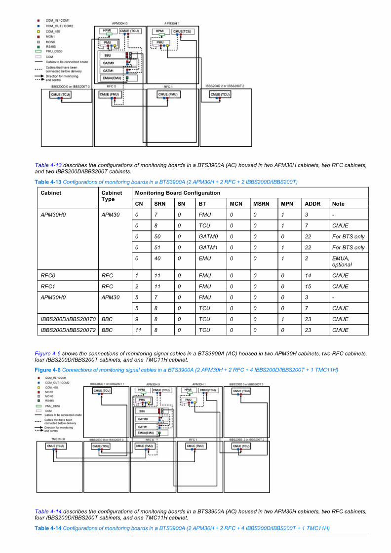
Table 413 describes the configurations of monitoring boards in a BTS3900A (AC) housed in two APM30H cabinets, two RFC cabinets,and two IBBS200D/IBBS200T cabinets.
Table 413 Configurations of monitoring boards in a BTS3900A (2 APM30H + 2 RFC + 2 IBBS200D/IBBS200T)
Cabinet CabinetType
Monitoring Board Configuration
CN SRN SN BT MCN MSRN MPN ADDR Note
APM30H0 APM30 0 7 0 PMU 0 0 1 3
0 8 0 TCU 0 0 1 7 CMUE
0 50 0 GATM0 0 0 0 22 For BTS only
0 51 0 GATM1 0 0 1 22 For BTS only
0 40 0 EMU 0 0 1 2 EMUA,optional
RFC0 RFC 1 11 0 FMU 0 0 0 14 CMUE
RFC1 RFC 2 11 0 FMU 0 0 0 15 CMUE
APM30H0 APM30 5 7 0 PMU 0 0 0 3
5 8 0 TCU 0 0 0 7 CMUE
IBBS200D/IBBS200T0 BBC 9 8 0 TCU 0 0 1 23 CMUE
IBBS200D/IBBS200T2 BBC 11 8 0 TCU 0 0 0 23 CMUE
Figure 46 shows the connections of monitoring signal cables in a BTS3900A (AC) housed in two APM30H cabinets, two RFC cabinets,four IBBS200D/IBBS200T cabinets, and one TMC11H cabinet.
Figure 46 Connections of monitoring signal cables in a BTS3900A (2 APM30H + 2 RFC + 4 IBBS200D/IBBS200T + 1 TMC11H)
Table 414 describes the configurations of monitoring boards in a BTS3900A (AC) housed in two APM30H cabinets, two RFC cabinets,four IBBS200D/IBBS200T cabinets, and one TMC11H cabinet.
Table 414 Configurations of monitoring boards in a BTS3900A (2 APM30H + 2 RFC + 4 IBBS200D/IBBS200T + 1 TMC11H)

Cabinet CabinetType
Monitoring Board Configuration
CN SRN SN BT MCN MSRN MPN ADDR Note
APM30H0 APM30 0 7 0 PMU 0 0 1 3
0 8 0 TCU 0 0 1 7 CMUE
0 50 0 GATM0 0 0 0 22 For BTS only
0 51 0 GATM1 0 0 1 22 For BTS only
0 40 0 EMU 0 0 1 2 EMUA,optional
RFC0 RFC 1 11 0 FMU 0 0 0 14 CMUE
RFC1 RFC 2 11 0 FMU 0 0 0 15 CMUE
APM30H1 APM30 5 7 0 PMU 0 0 0 3
5 8 0 TCU 0 0 0 7 CMUE
TMC11H0 TMC 8 8 0 TCU 0 0 0 6
IBBS200D/IBBS200T0 BBC 9 8 0 TCU 0 0 1 23 CMUE
IBBS200D/IBBS200T1 BBC 10 8 0 TCU 0 0 1 24 CMUE
IBBS200D/IBBS200T2 BBC 11 8 0 TCU 0 0 0 23 CMUE
IBBS200D/IBBS200T3 BBC 12 8 0 TCU 0 0 0 24 CMUE
Scenario 5: Example of Configurations in a BTS3900A (48 V DC)Figure 47 shows the connections of monitoring signal cables in a BTS3900A (48 V DC) housed in two TMC11H cabinets and two RFCcabinets. If cabinet TMC11H1 is not configured, connect the CMUE in cabinet RFC0 to the CMUE in cabinet RFC1. Ignore theconfiguration data of cabinet TMC11H1 in Table 415.
Figure 47 Connections of monitoring signal cables in a BTS3900A (2 TMC11H + 2 RFC)
Table 415 describes the configurations of monitoring boards in a BTS3900A housed in two TMC11H cabinets and two RFC cabinets.
Table 415 Configurations of monitoring boards in a BTS3900A (2 TMC11H + 2 RFC)
Cabinet CabinetType
Monitoring Board Configuration
CN SRN SN BT MCN MSRN MPN ADDR Note
TMC11H0 TMC 0 8 0 TCU 0 0 1 7 CMUE
0 50 0 GATM0 0 0 0 22 For BTS only
0 51 0 GATM1 0 0 1 22 For BTS only
0 40 0 EMU 0 0 1 2 EMUA,optional
RFC0 RFC 1 11 0 FMU 0 0 0 14 CMUE
RFC1 RFC 2 11 0 FMU 0 0 0 15 CMUE
TMC11H1 TMC 8 8 0 TCU 0 0 0 6 CMUE

Scenario 6: Example of Configurations in a DBS3900 (AC)Figure 48 shows the connections of monitoring signal cables in a DBS3900 (AC) housed in two APM30H cabinets, twoIBBS200D/IBBS200T cabinets, and one TMC11H cabinet.
Figure 48 Connections of monitoring signal cables in a DBS3900 (2 APM30H + 2 IBBS200D/IBBS200T + 1 TMC11H)
Table 416 describes the configurations of monitoring boards in a DBS3900 (AC) housed in two APM30H cabinets, twoIBBS200D/IBBS200T cabinets, and one TMC11H cabinet.
Table 416 Configurations of monitoring boards in a DBS3900 (2 APM30H + 2 IBBS200D/IBBS200T + 1 TMC11H)
Cabinet CabinetType
Monitoring Board Configuration
CN SRN SN BT MCN MSRN MPN ADDR Note
APM30H0 APM30 0 7 0 PMU 0 0 1 3
0 8 0 TCU 0 0 1 7 CMUE
0 40 0 EMU 0 0 1 2 EMUA,optional
APM30H1 APM30 5 7 0 PMU 0 0 0 3
5 8 0 TCU 0 0 0 6 CMUE
TMC11H0 TMC 8 8 0 TCU 0 0 0 7 CMUE
IBBS200D/IBBS200T0 BBC 9 8 0 TCU 0 0 1 23 CMUE
IBBS200D/IBBS200T2 BBC 11 8 0 TCU 0 0 0 23 CMUE
Figure 49 shows the connections of monitoring signal cables in a DBS3900 (AC) housed in two APM30H cabinets, fourIBBS200D/IBBS200T cabinets, and one TMC11H cabinet.
Figure 49 Connections of monitoring signal cables in a DBS3900 (2 APM30H + 4 IBBS200D/IBBS200T + 1 TMC11H)
Table 417 describes the configurations of monitoring boards in a DBS3900 (AC) housed in two APM30H cabinets, four

IBBS200D/IBBS200T cabinets, and one TMC11H cabinet.
Table 417 Configurations of monitoring boards in a DBS3900 (2 APM30H + 4 IBBS200D/IBBS200T + 1 TMC11H)
Cabinet CabinetType
Monitoring Board Configuration
CN SRN SN BT MCN MSRN MPN ADDR Note
APM30H0 APM30 0 7 0 PMU 0 0 1 3
0 8 0 TCU 0 0 1 7 CMUE
0 40 0 EMU 0 0 1 2 EMUA,optional
APM30H1 APM30 5 7 0 PMU 0 0 0 3
5 8 0 TCU 0 0 0 6 CMUE
TMC11H0 TMC 8 8 0 TCU 0 0 0 7 CMUE
IBBS200D/IBBS200T0 BBC 9 8 0 TCU 0 0 1 23 CMUE
IBBS200D/IBBS200T1 BBC 10 8 0 TCU 0 0 1 24 CMUE
IBBS200D/IBBS200T2 BBC 11 8 0 TCU 0 0 0 23 CMUE
IBBS200D/IBBS200T3 BBC 12 8 0 TCU 0 0 0 24 CMUE
Figure 410 shows the connections of monitoring signal cables in a DBS3900 in the remote monitoring scenario.
Figure 410 Connections of monitoring signal cables in a DBS3900 in the remote monitoring scenario
Table 418 describes the configurations of monitoring boards in a DBS3900 in the remote monitoring scenario.
Table 418 Configurations of monitoring boards in a DBS3900 in the remote monitoring scenario
Cabinet CabinetType
Monitoring Board Configuration
CN SRN SN BT MCN MSRN MPN ADDR Note
APM30H0 APM30 10 7 0 PMU Cabinetnumber ofthe RRUthatconnectsto thisPMU
Subracknumber ofthe RRUthatconnectsto thisPMU
0 3
10 8 0 TCU Cabinetnumber ofthe RRUthatconnectsto thisTCU
Subracknumber ofthe RRUthatconnectsto thisTCU
0 7 CMUE
10 40 0 EMU Cabinetnumber ofthe RRUthatconnectsto this
Subracknumber ofthe RRUthatconnectsto this
0 2
EMU EMU
IBBS200D/IBBS200T0 BBC 11 8 0 TCU Cabinetnumber ofthe RRUthatconnectsto thisTCU
Subracknumber ofthe RRUthatconnectsto thisTCU
0 23 CMUE
IBBS200D/IBBS200T1 BBC 12 8 0 TCU Cabinetnumber ofthe RRUthatconnectsto thisTCU
Subracknumber ofthe RRUthatconnectsto thisTCU
0 24 CMUE
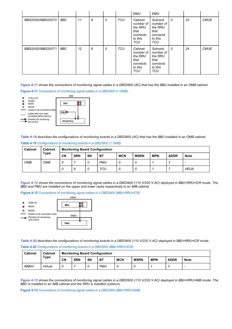
Figure 411 shows the connections of monitoring signal cables in a DBS3900 (AC) that has the BBU installed in an OMB cabinet.
Figure 411 Connections of monitoring signal cables in a DBS3900 (1 OMB)
Table 419 describes the configurations of monitoring boards in a DBS3900 (AC) that has the BBU installed in an OMB cabinet.
Table 419 Configurations of monitoring boards in a DBS3900 (1 OMB)
Cabinet CabinetType
Monitoring Board Configuration
CN SRN SN BT MCN MSRN MPN ADDR Note
OMB OMB 0 7 0 PMU 0 0 1 3
0 8 0 TCU 0 0 1 7 HEUA
Figure 412 shows the connections of monitoring signal cables in a DBS3900 (110 V/220 V AC) deployed in BBU+RRU+ICR mode. TheBBU and PMU are installed on the upper and lower racks respectively in an IMB cabinet.
Figure 412 Connections of monitoring signal cables in a DBS3900 (BBU+RRU+ICR)
Table 420 describes the configurations of monitoring boards in a DBS3900 (110 V/220 V AC) deployed in BBU+RRU+ICR mode.
Table 420 Configurations of monitoring boards in a DBS3900 (BBU+RRU+ICR)
Cabinet CabinetType
Monitoring Board Configuration
CN SRN SN BT MCN MSRN MPN ADDR Note
IMB03 Virtual 0 7 0 PMU 0 0 1 3
Figure 413 shows the connections of monitoring signal cables in a DBS3900 (110 V/220 V AC) deployed in BBU+RRU+IMB mode. TheBBU is installed in an IMB cabinet and the RRU is installed outdoors.
Figure 413 Connections of monitoring signal cables in a DBS3900 (BBU+RRU+IMB)

Table 421 describes the configurations of monitoring boards in a DBS3900 (110 V/220 V AC) deployed in BBU+RRU+IMB mode.
Table 421 Configurations of monitoring boards in a DBS3900 (BBU+RRU+IMB)
Cabinet CabinetType
Monitoring Board Configuration
CN SRN SN BT MCN MSRN MPN ADDR Note
IMB03 Virtual 0 7 0 PMU 0 0 1 3
Scenario 7: Example of Configurations in a DBS3900 (48 V DC)Figure 414 shows the connections of monitoring signal cables in a DBS3900 (48 V DC) housed in two TMC11H cabinets.
Figure 414 Connections of monitoring signal cables in a DBS3900 (2 TMC11H)
Table 422 describes the configurations of monitoring boards in a DBS3900 (48 V DC) housed in two TMC11H cabinets.
Table 422 Configurations of monitoring boards in a DBS3900 (2 TMC11H)
Cabinet CabinetType
Monitoring Board Configuration
CN SRN SN BT MCN MSRN MPN ADDR Note
TMC11H0 TMC 0 8 0 TCU 0 0 1 7 CMUE
TMC11H1 TMC 8 8 0 TCU 0 0 0 7 CMUE
Figure 415 shows the connections of monitoring signal cables in a DBS3900 (48 V DC) that has the BBU installed in an OMB cabinet.
Figure 415 Connections of monitoring signal cables in a DBS3900 (1 OMB)
Table 423 describes the configurations of monitoring boards in a DBS3900 (48 V DC) that has the BBU installed in an OMB cabinet.
Table 423 Configurations of monitoring boards in a DBS3900 (1 OMB)
Cabinet CabinetType
Monitoring Board Configuration
CN SRN SN BT MCN MSRN MPN ADDR Note
OMB OMB 0 8 0 TCU 0 0 1 7 HEUA
Scenario 8: Example of Configurations in a BTS3900AL (AC)Figure 416 shows the connections of monitoring signal cables in a BTS3900AL (AC) housed in one AC cabinet, one DC cabinet, andone TMC11H cabinet. If the HAUs are not configured, connect the CMUA directly to port D_COM3 on the CCU. Ignore the HAUconfiguration data of cabinet BTS3900AL AC0 in Table 424Figure 417Table 425.
Figure 416 Connections of monitoring signal cables in a BTS3900AL (1 AC cabinet + 1 DC cabinet + 1 TMC11H)
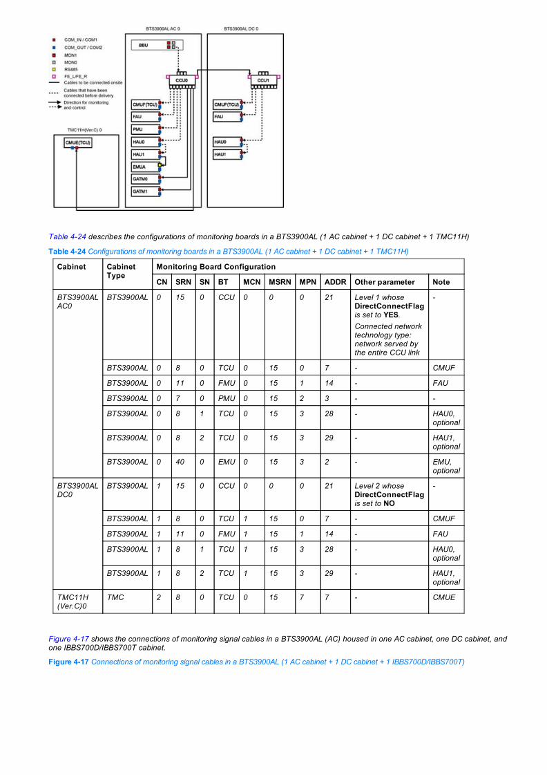
Table 424 describes the configurations of monitoring boards in a BTS3900AL (1 AC cabinet + 1 DC cabinet + 1 TMC11H)
Table 424 Configurations of monitoring boards in a BTS3900AL (1 AC cabinet + 1 DC cabinet + 1 TMC11H)
Cabinet CabinetType
Monitoring Board Configuration
CN SRN SN BT MCN MSRN MPN ADDR Other parameter Note
BTS3900ALAC0
BTS3900AL 0 15 0 CCU 0 0 0 21 Level 1 whoseDirectConnectFlagis set to YES.Connected networktechnology type:network served bythe entire CCU link
BTS3900AL 0 8 0 TCU 0 15 0 7 CMUF
BTS3900AL 0 11 0 FMU 0 15 1 14 FAU
BTS3900AL 0 7 0 PMU 0 15 2 3
BTS3900AL 0 8 1 TCU 0 15 3 28 HAU0,optional
BTS3900AL 0 8 2 TCU 0 15 3 29 HAU1,optional
BTS3900AL 0 40 0 EMU 0 15 3 2 EMU,optional
BTS3900ALDC0
BTS3900AL 1 15 0 CCU 0 0 0 21 Level 2 whoseDirectConnectFlagis set to NO
BTS3900AL 1 8 0 TCU 1 15 0 7 CMUF
BTS3900AL 1 11 0 FMU 1 15 1 14 FAU
BTS3900AL 1 8 1 TCU 1 15 3 28 HAU0,optional
BTS3900AL 1 8 2 TCU 1 15 3 29 HAU1,optional
TMC11H(Ver.C)0
TMC 2 8 0 TCU 0 15 7 7 CMUE
Figure 417 shows the connections of monitoring signal cables in a BTS3900AL (AC) housed in one AC cabinet, one DC cabinet, andone IBBS700D/IBBS700T cabinet.
Figure 417 Connections of monitoring signal cables in a BTS3900AL (1 AC cabinet + 1 DC cabinet + 1 IBBS700D/IBBS700T)

Table 425 describes the configurations of monitoring boards in a BTS3900AL (AC) housed in one AC cabinet, one DC cabinet, andone IBBS700D/IBBS700T cabinet.
Table 425 Configurations of monitoring boards in a BTS3900AL (1 AC cabinet + 1 DC cabinet + 1 IBBS700D/IBBS700T)
Cabinet CabinetType
Monitoring Board Configuration
CN SRN SN BT MCN MSRN MPN ADDR Other parameter Note
BTS3900AL AC0 BTS3900AL 0 15 0 CCU 0 0 0 21 Level 1 whoseDirectConnectFlagis set to YES.Connected networktechnology type:network served bythe entire CCU link
BTS3900AL 0 8 0 TCU 0 15 0 7 CMUF
BTS3900AL 0 11 0 FMU 0 15 1 14 FAU
BTS3900AL 0 7 0 PMU 0 15 2 3
BTS3900AL 0 8 1 TCU 0 15 3 28 HAU0,optional
BTS3900AL 0 8 2 TCU 0 15 3 29 HAU1,optional
BTS3900AL 0 40 0 EMU 0 15 3 2 EMU,optional
BTS3900AL DC0 BTS3900AL 1 15 0 CCU 0 0 0 21 Level 2 whoseDirectConnectFlagis set to NO
BTS3900AL 1 8 0 TCU 1 15 0 7 CMUF
BTS3900AL 1 11 0 FMU 1 15 1 14 FAU
BTS3900AL 1 8 1 TCU 1 15 3 28 HAU0,optional
BTS3900AL 1 8 2 TCU 1 15 3 29 HAU1,optional
IBBS700D/IBBS700T0 BBC 3 15 0 CCU 0 0 0 21 Level 3 whoseDirectConnectFlagis set to NO
BBC 3 8 0 TCU 3 15 0 7 CMUF
BBC 3 8 1 TCU 3 15 3 28 HAU0,optional
BBC 3 8 2 TCU 3 15 3 29 HAU1,optional
4.4.4 Precautions
N/A
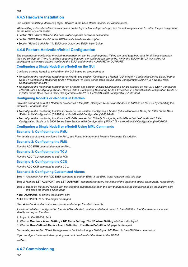
4.4.5 Hardware InstallationSee section "Installing Monitoring Signal Cables" in the base stationspecific installation guide.
When setting external Boolean alarms based on the high or low voltage settings, see the following sections to obtain the pin assignmentfor the wires of alarm cables:Section "BBU Alarm Cable" in the base stationspecific hardware description.Section "RRU Alarm Cable" in the RRUspecific hardware description.Section "RS485 Serial Port" in EMU User Guide and EMUA User Guide.
4.4.6 Feature Activation/Initial ConfigurationThe scenarios for configuring monitoring management can be used together. If they are used together, data for all these scenariosmust be configured. There is no fixed sequence between the configuration scenarios. When the EMU or EMUA is installed forconfiguring customized alarms, configure the EMU, and then the ALMPORT or OUTPORT.
Configuring a Single NodeB or eNodeB on the GUIConfigure a single NodeB or eNodeB on the GUI based on prepared data.
To configure the monitoring function for a NodeB, see section "Configuring a NodeB (GUI Mode) > Configuring Device Data About aNodeB > Configuring Monitoring Units > Procedure" in 3900 Series Base Station Initial Configuration (SRAN7.0) > NodeB InitialConfiguration(V200R014).To configure the monitoring function for an eNodeB, see section "Initially Configuring a Single eNodeB on the CME GUI > ConfiguringeNodeB Data > Configuring eNodeB Device Data > Configuring Monitoring Units > Procedure in eNodeB Initial Configuration Guide orin 3900 Series Base Station Initial Configuration (SRAN7.0) > eNodeB Initial Configuration(V100R005).
Configuring NodeBs or eNodeBs in BatchesSave the prepared data of a NodeB or eNodeB as a template. Configure NodeBs or eNodeBs in batches on the GUI by importing thetemplate. For details, see:
To configure the monitoring function for NodeBs, see section "Configuring a NodeB (Iub Collaboration Mode)" in 3900 Series BaseStation Initial Configuration (SRAN7.0) > NodeB Initial Configuration(V200R014).To configure the monitoring function for eNodeBs, see section "Initially Configuring eNodeBs in Batches" in eNodeB InitialConfiguration Guide or in 3900 Series Base Station Initial Configuration (SRAN7.0) > eNodeB Initial Configuration(V100R005).
Configuring a Single NodeB or eNodeB Using MML CommandsScenario 1: Configuring the PMUFor details about how to configure the PMU, see Power Management Feature Parameter Description.
Scenario 2: Configuring the FMURun the ADD FMU command to add an FMU.
Scenario 3: Configuring the TCURun the ADD TCU command to add a TCU.
Scenario 4: Configuring the CCURun the ADD CCU command to add a CCU.
Scenario 5: Configuring Customized AlarmsStep 1 (Optional) Run the ADD EMU command to add an EMU. If the EMU is not required, skip this step.
Step 2 Run the LST ALMPORT and LST OUTPORT commands to query the status of the input and output alarm ports, respectively.
Step 3 Based on the query results, run the following commands to open the port that needs to be configured as an input alarm portand close the unused alarm port:
SET ALMPORT: to set the input alarm portSET OUTPORT: to set the output alarm port
Step 4 Add and bind a customized alarm, and change the alarm severity.
A customized alarm configured on the NodeB or eNodeB must be added and bound to the M2000 so that the alarm console canidentify and report the alarm.
1. Log in to the M2000 client.2. Choose Monitor > Alarm Setting > NE Alarm Setting. The NE Alarm Setting window is displayed.3. Choose UserDefined Alarm > Alarm Definition. The Alarm Definition tab page is displayed.
For details, see section "Fault Management > Fault Monitoring > Defining an NE Alarm" in the M2000 documentation.
If you configure the output alarm port, you do not need to bind the alarm to the M2000.
End
4.4.7 CommissioningN/A

4.4.8 Activation VerificationTo verify the monitoring function, perform the following steps:
Step 1 Run the following MML commands to check whether the PMU, FMU, TCU, and EMU boards are working properly:
DSP PMUDSP FMUDSP TCUDSP CCUDSP EMUIf the system returns any command output for a board, the board is working properly. When all the boards are working properly,proceed to Step 2.
Step 2 Perform the operations described in Table 426 and check whether ambient alarms are correctly reported. If alarms cannot bereported, check hardware connections and software configurations.
Table 426 Verifying monitoring alarms
Alarm ID Alarm Name Alarm Triggering Method Remarks
25652 CabinetTemperatureUnacceptable
Set the upper limit of the cabinettemperature alarm TUTHD 5°Clower than the ambienttemperature or set the lower limitof TLTHD 5°C higher than theambient temperature, and waitmore than 10s.Set the preceding parametersonly when the PMU, TCU, or FMUis configured. Select theconfiguration object of the boardto which the sensor is connected.
This alarm is reported onlywhen the temperature sensor isconfigured by default or isinstalled in the cabinet.The temperature sensor is notconfigured by default in theBTS3900, BTS3900L, orBTS3900C cabinet.The temperature sensor isconfigured by default in theBTS3900A (with RFC),DBS3900 (with RFC), andBTS3900AL cabinets.
25672 Burglar Alarm Open the cabinet door and waitmore than 10s.
This alarm is reported onlywhen the door status sensor isconfigured by default or isinstalled in the cabinet.The door status sensor is notconfigured by default in theBTS3900, BTS3900L, DBS3900(with OMB or IMB), orBTS3900C cabinet.The door status sensor isconfigured by default in theBTS3900A, DBS3900 (withAPM30H or TMC), andBTS3900AL cabinets.
25654 BatteryTemperatureUnacceptable
In a high temperature scenario:Set the upper limit of the batterytemperature alarm TUTHD lowerthan the ambient temperature orset the ambient temperaturehigher than the upper limit, andwait more than 2s.In a low temperature scenario: Setthe lower limit of the batterytemperature alarm TLTHD higherthan the ambient temperature orset the ambient temperature lowerthan the lower limit, and wait morethan 2s.Set the preceding parametersonly when the battery isconfigured. For details, see PowerManagement Feature ParameterDescription.
This alarm is reported onlywhen the battery is configuredin the cabinet.
25650 AmbientTemperatureUnacceptable
In a high temperature scenario:Set the upper limit of the ambienttemperature alarm TUTHD lowerthan the ambient temperature orset the ambient temperaturehigher than the upper limit, andwait more than 2s.In a low temperature scenario: Setthe lower limit of the ambienttemperature alarm TLTHD higher
This alarm is reported onlywhen the EMU or EMUA isconfigured.

than the ambient temperature orset the ambient temperature lowerthan the lower limit, and wait morethan 2s.Set the preceding parametersonly when the EMU is configured.
25651 AmbientHumidityUnacceptable
In a high humidity scenario: Setthe upper limit of the ambienthumidity alarm HUTHD lower thanthe ambient humidity or set theambient humidity higher than theupper limit, and wait more than2s.In a low humidity scenario: Set thelower limit of the ambient humidityalarm HLTHD higher than theambient humidity or set theambient humidity lower than thelower limit, and wait more than 2s.Set the preceding parametersonly when the EMU is configured.
25653 CabinetHumidityUnacceptable
Set the upper limit of the cabinethumidity alarm HUTHD 10% RHlower than the cabinet humidity orset the lower limit of HLTHD 10%RH higher than the cabinethumidity, and wait more than 10s.Set the preceding parametersonly when the EMU is configured.
25670 Water Alarm Perform any of the followingoperations:Place the water sensor in waterfor more than 10s.Disconnect the water sensor.
25671 Smoke Alarm Perform any of the followingoperations:Generate smoke around thesmoke sensor for more than15s.Disconnect the smoke sensorand set the smoke sensor alarmto high voltage.
Step 3 If a customized Boolean alarm device is connected, check whether an alarm is reported by setting the alarm device to high levelor low level. Verify that the alarms are correctly configured.
End
4.4.9 ReconfigurationWhen you reconfigure parameters for monitoring devices, collect information about parameters to be reconfigured based on onsitehardware configuration and environment monitoring requirements. For details, see section 4.4.3 "Data Preparation."
Run the MOD PMU command to reconfigure PMU parameters.
Run the MOD FMU command to reconfigure FMU parameters.
Run the MOD TCU command to reconfigure TCU parameters.
Run the MOD CCU command to reconfigure CCU parameters.
Run the MOD EMU command to reconfigure EMU parameters.
4.4.10 DeactivationN/A
4.5 OptimizationN/A
4.6 TroubleshootingTable 427 lists common alarms related to monitoring device faults and Table 426 lists common alarms related to environmentexceptions. For details about how to clear these alarms, see NodeB Alarm Reference and eNodeB Alarm Reference.
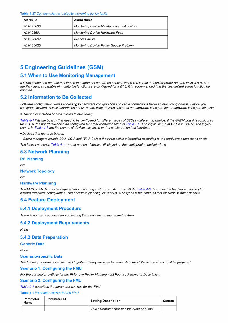
Table 427 Common alarms related to monitoring device faults
Alarm ID Alarm Name
ALM25600 Monitoring Device Maintenance Link Failure
ALM25601 Monitoring Device Hardware Fault
ALM25602 Sensor Failure
ALM25620 Monitoring Device Power Supply Problem
5 Engineering Guidelines (GSM)5.1 When to Use Monitoring ManagementIt is recommended that the monitoring management feature be enabled when you intend to monitor power and fan units in a BTS. Ifauxiliary devices capable of monitoring functions are configured for a BTS, it is recommended that the customized alarm function beenabled.
5.2 Information to Be CollectedSoftware configuration varies according to hardware configuration and cable connections between monitoring boards. Before youconfigure software, collect information about the following devices based on the hardware configuration or hardware configuration plan:
Planned or installed boards related to monitoring
Table 41 lists the boards that need to be configured for different types of BTSs in different scenarios. If the GATM board is configuredfor a BTS, the board must also be configured for other scenarios listed in Table 41. The logical name of GATM is GATM. The logicalnames in Table 41 are the names of devices displayed on the configuration tool interface.
Devices that manage boardsBoard managers include BBU, CCU, and RRU. Collect their respective information according to the hardware connections onsite.
The logical names in Table 41 are the names of devices displayed on the configuration tool interface.
5.3 Network PlanningRF PlanningN/A
Network TopologyN/A
Hardware PlanningThe EMU or EMUA may be required for configuring customized alarms on BTSs. Table 42 describes the hardware planning forcustomized alarm configuration. The hardware planning for various BTSs types is the same as that for NodeBs and eNodeBs.
5.4 Feature Deployment
5.4.1 Deployment ProcedureThere is no fixed sequence for configuring the monitoring management feature.
5.4.2 Deployment RequirementsNone
5.4.3 Data PreparationGeneric DataNone
Scenariospecific DataThe following scenarios can be used together. If they are used together, data for all these scenarios must be prepared.
Scenario 1: Configuring the PMUFor the parameter settings for the PMU, see Power Management Feature Parameter Description.
Scenario 2: Configuring the FMUTable 51 describes the parameter settings for the FMU.
Table 51 Parameter settings for the FMU
ParameterName
Parameter ID Setting Description Source
This parameter specifies the number of the

Cabinet No. CN
cabinet housing the FMU.If the number of the RFC housing the FMU is 1,set this parameter to 1.For details, see Base Station Cabinets andSubracks (Including the BBU Subrack)Configuration.
Networkplan
Subrack No. SRN
This parameter specifies the number of thesubrack housing the FMU.Set this parameter to 11 or 12.For details, see Base Station Cabinets andSubracks (Including the BBU Subrack)Configuration.
Networkplan
Slot No. SNThis parameter specifies the number of the slothousing the FMU.Set this parameter to the default value 0.
Networkplan
Board Type BT Set this parameter to FMU. Networkplan
BoardParameterConfigurationEnabled
CFGFLAGThis parameter specifies whether FMUconfiguration is allowed.Set this parameter to Yes.
Networkplan
SmartTemperatureControl
STC
This parameter specifies whether to enablesmart temperature control.When this parameter is set to ENABLED, theFMU adjusts the fan speed according to thetemperature control parameters delivered bythe BBU. In this mode, the fan noise is low.When this parameter is set to DISABLED, theFMU automatically adjusts fan speedaccording to the ambient temperature. In thismode, the fan noise is high.
This parameter can be set to ENABLED orDISABLED.ENABLED is recommended.
Networkplan
SpecialBooleanAlarm Flag
SBAF
This parameter specifies whether to report adedicated Boolean alarm. If the shield flag for aBoolean alarm is selected, the Boolean alarmcannot be reported.Value range: SMDISABLE(SmogLowLevel),WIDISABLE(WaterImmersedLowLevel),GMDISABLE(GateMagnetismLowLevel),ARRESTER1(LightningArrester1LowLevel),andARRESTER2(LightningArrester2LowLevel)It is recommended that the FMU not beconnected to external sensors and all sensorsbe disabled. If you want to use the sensors,contact Huawei technical support.Retain the default settings, which mean that allsensors are disabled.
Networkplan
SpecialAlarm ValidLevelConfiguration
SPECIALSWITCHERLEVEL
This parameter specifies the level specificationsfor the dedicated Boolean alarm. There are twospecifications: highlevel and lowlevel alarms.It is recommended that the dedicated Booleanalarm function be disabled on the FMU. WhenSBAF is disabled, this parameter does notneed to be configured.
Networkplan
ManagerCabinet No. MCN
This parameter specifies the cabinet number ofthe TMU, CCU, or RXU. TMU, CCU, and RXUare the logical names of the GTMU, CCU, andRRU respectively.During site configuration, the FMU is notdirectly connected to the RXU. Set thisparameter to the cabinet number of the TMU orCCU that connects to the FMU.
Networkplan
ManagerSubrack No. MSRN
This parameter specifies the subrack number ofthe TMU, CCU, or RXU. TMU, CCU, and RXUare the logical names of the GTMU, CCU, andRRU respectively.During site configuration, the FMU is not
Networkplan

directly connected to the RXU. Set thisparameter to the subrack number of the TMUor CCU that connects to the FMU.
ManagerPort No. MPN
This parameter specifies the number of theserial port on the manager to which the FMU isconnected.If the FMU is connected to the BBU:UPEU/UEIU (MON1): 1UPEU/UEIU (MON0): 0
If the FMU is connected to the CCU, it must beconnected to port D_COM1. Set this parameter to1.
Networkplan
Address ADDR
This parameter specifies the communicationaddress of the FMU. A maximum of two FMUscan be configured on an RS485 bus.Set this parameter as follows:Upperlevel FMU in two cascaded FMUs: 14Lowerlevel FMU in two cascaded FMUs: 15
Networkplan
FMU BoardType FMUTYPE
This parameter specifies the FMUA board type.Set this parameter to OUTDOOR when theFMUA is installed in an outdoor cabinet.Set this parameter to INDOOR when theFMUA is installed in an indoor cabinet.
Networkplan
TemperatureControlMode
TCMODE
This parameter specifies which mode is used toadjust the fan speed. Set this parameter to Default.The default mode achieves a tradeoff amongpower consumption, noise, and temperaturecontrol. It applies to most scenarios.
NetworkPlan
Scenario 3: Configuring the TCUTable 52 describes the parameter settings for the TCU. Parameters that are not listed in the table do not need to be configured for the3900 series base stations.
Table 52 Parameter settings for the TCU
Parameter Name Parameter ID Setting Description Source
Cabinet No. CN
This parameter specifies the number ofthe cabinet housing the TCU.If the number of the RFC housing theTCU is 1, set this parameter to 1.For details, see Base Station Cabinetsand Subracks (Including the BBUSubrack) Configuration.
Networkplan
Subrack No. SRN
This parameter specifies the number ofthe subrack housing the TCU.Set this parameter to 8 or 14.For details, see Base Station Cabinetsand Subracks (Including the BBUSubrack) Configuration.
Networkplan
Slot No. SN
This parameter specifies the number ofthe slot housing the TCU.If the TCU is installed in the BTS3900ALAC, BTS3900AL DC, IBBS700D, orIBBS700T cabinet, set this parameter asfollows:Set the slot number of the CMUF to 0.Set the slot number of HAU0 to 1.Set the slot number of HAU1 to 2.
If the TCU is installed in the TP48600Acabinet, set this parameter as follows:Set the slot number of the CMUF forcabinet temperature control to 0.Set the slot number of the CMUF forbattery cabinet temperature control to1.Set the slot number of HAU0 to 2.
Networkplan

Set the slot number of HAU1 to 3.If the TCU is installed on other cabinet,set this parameter to 0.
Board Type BT Set this parameter to TCU. Networkplan
Board ParameterConfigurationEnabled
CFGFLAGThis parameter specifies whether TCUconfiguration is allowed.Set this parameter to Yes.
Networkplan
TemperatureAlarm UpperThreshold
TUTHD
This parameter specifies the uppertemperature limit for the cabinet. If thetemperature exceeds the upper limit, thealarm ALM25652 Cabinet TemperatureUnacceptable is reported.It is recommended that this parameterbe set to 50 for the TCU in the BBC and68 for the TCU in other cabinets.
Networkplan
TemperatureAlarm LowerThreshold
TLTHD
This parameter specifies the lowertemperature limit for the cabinet. If thetemperature exceeds the lower limit, thealarm ALM25652 Cabinet TemperatureUnacceptable is reported.The default value is recommended forthis parameter.
Networkplan
Manager CabinetNo. MCN
This parameter specifies the cabinetnumber of the TMU, CCU, or RXU.TMU, CCU, and RXU are the logicalnames of the GTMU, CCU, and RRUrespectively.
Networkplan
Manager SubrackNo. MSRN
This parameter specifies the subracknumber of the TMU, CCU, or RXU.TMU, CCU, and RXU are the logicalnames of the GTMU, CCU, and RRUrespectively.
Networkplan
Manager Port No. MPN
This parameter specifies the number ofthe serial port on the manager to whichthe TCU is connected.If the TCU is connected to the BBU:UPEU/UEIU (MON1): 1UPEU/UEIU (MON0): 0
If the TCU is connected to the CCU:CMUF is permanently connected toport D_COM0, set this parameter to 0;FAU0 and FAU1 are permanentlyconnected to port D_COM3, set thisparameter to 3;If the TCU is connected to the RRU,set this parameter to 0.
Networkplan
Address ADDR
In the APM30H or TMC11H cabinet, amaximum of two TCUs can beconfigured on an RS485 bus.Set this parameter as follows:Upperlevel TCU in two cascadedTCUs: 7Lowerlevel TCU in two cascadedTCUs: 6
In the IBBS200D/IBBS200T cabinet, amaximum of four TCUs can beconfigured on an RS485 bus.Set this parameter as follows:If the upperlevel TCU is managed bythe PMU whose communicationaddress is 3, set this parameter to 23.If the lowerlevel TCU is managed bythis PMU, set this parameter to 24.If the upperlevel TCU is managed bythe PMU whose communicationaddress is 4, set this parameter to 25.If the lowerlevel TCU is managed bythis PMU, set this parameter to 26.
Networkplan

If the HAUs are installed, a maximum oftwo TCUs can be configured on anRS485 bus.Set this parameter as follows:Upperlevel TCU in two cascadedTCUs: 28Lowerlevel TCU in two cascadedTCUs: 29
Alarm ParameterConfigurationEnabled
ALMPARACFGFLAG
This parameter specifies whether toenable SBAF.It is recommended that this parameterbe set to No, which means that SBAF isdisabled.
Networkplan
Special BooleanAlarm Flag SBAF
This parameter specifies whether toreport a dedicated Boolean alarm. If theshield flag for a Boolean alarm isselected, the Boolean alarm cannot bereported.Value range: WS_DISABLE(WaterImmersed Sensor Disabled) andSS_DISABLE(Smog Sensor Disabled).It is recommended that the TCU not beconnected to external sensors and allsensors be disabled. If you want to usethe sensors, contact Huawei technicalsupport.Retain the default settings, which meanthat all sensors are disabled.
Networkplan
Scenario 4: Configuring the CCUTable 53 describes the parameter settings for the CCU.
Table 53 Parameter settings for the CCU
Parameter Name Parameter ID Setting Description Source
Cabinet No. CN
This parameter specifies the number of thecabinet housing the CCU.If the number of the BTS3900AL cabinethousing the CCU is 0, set this parameter to0.For details, see Base Station Cabinets andSubracks (Including the BBU Subrack)Configuration.
Networkplan
Subrack No. SRNThis parameter specifies the number of thesubrack housing the CCU.Set this parameter to the default value 15.
Networkplan
Slot No. SNThis parameter specifies the number of theslot housing the CCU.Set this parameter to the default value 0.
Networkplan
Board Type BT Set this parameter to CCU. Networkplan
Board ParameterConfigurationEnabled
CFGFLAGThis parameter specifies whether CCUconfiguration is allowed.Set this parameter to Yes.
Networkplan
Manager CabinetNo. MCN
This parameter specifies the cabinet numberof the TMU, CCU, or RXU. TMU, CCU, andRXU are the logical names of the GTMU,CCU, and RRU respectively.The CCU can only be managed by the TMU.
Networkplan
Manager SubrackNo. MSRN
This parameter specifies the subrack numberof the TMU, CCU, or RXU. TMU, CCU, andRXU are the logical names of the GTMU,CCU, and RRU respectively.The CCU can only be managed by the TMU.
Networkplan
Manager Port No. MPN
This parameter specifies the number of theserial port on the manager to which the CCUis connected. Network

The CCU must be connected to port MON0on the BBU. Therefore, this parameter mustbe set to 0.
plan
DirectConnectFlag DCF
This parameter specifies whether the CCUis directly connected to its manager. If theCCU is directly connected to its manager,set this parameter to YES.If the CCU is connected to its manager overa cascading CCU, set this parameter toNO.
Networkplan
Cascade No. CCN
This parameter specifies the insertedposition of the CCU on a CCUcascaded link.Set this parameter to 1 for the leftmost CCUon the link (the CCU whose port FE_L is notconnected). Set this parameter to an integerin ascending order for the other CCUs on thelink.
Networkplan
ConnectedStandard CS
This parameter specifies the networktechnology type of the BBU that is directlyconnected to the CCU. Set this parameter toGSM, UMTS, or LTE.The parameter is valid only when the DCF isset to Yes.
Networkplan
Special BooleanAlarm Flag SBAF
This parameter specifies whether to report adedicated Boolean alarm. If the shield flag fora Boolean alarm is selected, the Booleanalarm cannot be reported.Value range: WS_DISABLE(WaterImmersed Sensor Disabled) andSS_DISABLE(Smog Sensor Disabled).It is recommended that the CCU not beconnected to external sensors and allsensors be disabled. If you want to use thesensors, contact Huawei technical support.Retain the default settings, which mean thatthe water sensor and smoke sensor aredisabled.
Networkplan
Scenario 5: Configuring the GATMTable 54 describes the parameter settings for the GATM.
Table 54 Parameter settings for the GATM
Parameter Name Parameter ID Setting Description Source
Cabinet No. CN
This parameter specifies the number ofthe cabinet housing the GATM.If the number of the APM30H housing theGATM is 1, set this parameter to 1.For details, see Base Station Cabinetsand Subracks (Including the BBUSubrack) Configuration.
Networkplan
Subrack No. SRN
This parameter specifies the number ofthe subrack housing the GATM. It can beset to 40 or 59.For details, see Base Station Cabinetsand Subracks (Including the BBUSubrack) Configuration.
Networkplan
Slot No. SNThis parameter specifies the number ofthe slot housing the GATM.Set this parameter to the default value 0.
Networkplan
Board Type BT Set this parameter to GATM. Networkplan
Board ParameterConfigurationEnabled
CFGFLAGThis parameter specifies whether GATMconfiguration is allowed.Set this parameter to Yes.
Networkplan
This parameter specifies whether toprovide power supplies to towermountedamplifiers (TMAs) of branches 0 through

ANT0 ALD PowerSwitch~ ANT5 ALDPower Switch
AMPC0~ AMPC 5 5.If a branch is connected to a TMA, setthis parameter to ON.If a branch is not connected to a TMA,set this parameter to OFF.
Networkplan
ANT0 AlarmMode~ ANT5Alarm Mode
MODE0~ MODE 5
This parameter specifies the mode forreporting the feeding current alarms ofTMAs of branches 0 through 5. When thefeeding current exceeds the threshold, analarm is reported.Value range: MODE1, MODE2, andMODE3MODE1: Only major alarms arereported.MODE2: Warnings and major alarmsare reported. In this mode, bothwarnings and major alarms arereported as fixedvalue current.MODE3: Warnings and major alarmsare reported. In this mode, warningsare reported as periodic pulse current,and major alarms are reported as fixedvalue current. Periodic pulse current isreported when the alarm reportingrequirement is met within a presetperiod. Compared with fixedvaluecurrent, periodic pulse current is easilyreported.
It is recommended that this parameter beset to MODE1.
Networkplan
ANT0 ALD OverCritical AlarmThreshold(mA)~ANT5 ALD OverCritical AlarmThreshold(mA)
MAJORALMUP0~MAJORALMUP5
This parameter specifies the threshold forreporting the critical alarm related to thefeeding current of the TMA.When the feeding current of the TMAonsite exceeds this threshold, the alarmALM28002 GATM ALD Current Out ofRange is reported.
Networkplan
ANT0 ALD OverWarning AlarmThreshold(mA)~ANT5 ALD OverWarning AlarmThreshold(mA)
MINORALMUP0~MINORALMUP5
This parameter specifies the threshold forreporting the warning related to thefeeding current of the TMA. When thefeeding current of the TMA onsiteexceeds this threshold, the alarm ALM28002 GATM ALD Current Out of Rangeis reported.
Networkplan
ANT0 ALD LowCurrent AlarmThreshold(mA)~ANT5 ALD LowCurrent AlarmThreshold(mA)
ALMD0~ALMD5
This parameter specifies the threshold forreporting the warning related to thefeeding current of the TMA. When thefeeding current of the TMA onsiteexceeds this threshold, the alarm ALM28002 GATM ALD Current Out of Rangeis reported.
Networkplan
Manager CabinetNo. MCN
This parameter specifies the cabinetnumber of the TMU, CCU, or RXU. TMU,CCU, and RXU are the logical names ofthe GTMU, CCU, and RRU respectively.
Networkplan
Manager SubrackNo. MSRN
This parameter specifies the subracknumber of the TMU, CCU, or RXU. TMU,CCU, and RXU are the logical names ofthe GTMU, CCU, and RRU respectively.
Networkplan
Manager Port No. MPN
This parameter specifies the number ofthe serial port on the manager to whichthe GATM is connected.Set this parameter as follows:If the GATM is connected to the BBU:GATM0 is connected to MON0 on theUPEU. Set this parameter to 0.GATM1 is connected to MON1 on theUPEU. Set this parameter to 1.
If the GATM is connected to CCU:GATM0 is permanently connected toport D_COM5. Set this parameter to 5.
Networkplan

GATM1 is permanently connected toport D_COM6. Set this parameter to 6.
Address ADDRThis parameter specifies thecommunication address of the GATM.Set this parameter to 22.
Networkplan
Scenario 6: Configuring Customized AlarmsTo prepare data for customized alarm configuration, perform the following steps:
Step 1 Prepare EMU configuration data.
Before data preparation, check whether the EMU needs to be configured by referring to Table 42. If the EMU is required,prepare EMU configuration data by referring to Table 55. Otherwise, skip this step.
Step 2 Prepare configuration data of the alarm signal input and output ports based on the input and output requirements of customizedalarms.
Prepare configuration data of the environmental alarm signal input port ALMPORT by referring to Table 56.Prepare configuration data of the environmental alarm signal output port OUTPORT by referring to Table 57.
End
Table 55 Parameter settings for the EMU
ParameterName
Parameter ID Setting Description Source
Cabinet No. CN
This parameter specifies the numberof the cabinet housing the EMU.If the number of the BTS3900cabinet housing the EMU is 0, setthis parameter to 0.
Networkplan
Subrack No. SRN
This parameter specifies the numberof the subrack housing the EMU.Set this parameter to the defaultvalue.
Networkplan
Slot No. SN
This parameter specifies the numberof the slot housing the EMU.Set this parameter to the defaultvalue.
Networkplan
Board Type BT Set this parameter to EMU. Networkplan
BoardParameterConfigurationEnabled
CFGFLAGThis parameter specifies whetherEMU configuration is allowed.Set this parameter to Yes.
Networkplan
Special AnalogAlarm Flag SAAF
This parameter specifies whether toreport a dedicated Boolean alarm. Ifthe shield flag for a Boolean alarm isselected, the Boolean alarm cannotbe reported.Value range: 48V_DISABLE(48Voltage Disabled),RES0(Preserved Parameter0),RES1(Preserved Parameter1),RES2(Preserved Parameter2),TS_DISABLE(Temperature SensorDisabled), HS_DISABLE(HumiditySensor Disabled), RES3(PreservedParameter3), and RES4(PreservedParameter4)Set this parameter as follows:The 48 V alarm is used to checkwhether the input voltage for thecabinet is normal. When the inputvoltage for the cabinet is 48 V, it isrecommended that 48V_DISABLEbe cleared.RES0, RES1, and RES2 areparameters reserved by Huaweiand they are selected.Set the sensors according to thetypes of sensors connected to the
Networkplan

EMU or EMUA.
Special BooleanAlarm Flag SBAF
This parameter specifies whether toreport a dedicated Boolean alarm. Ifthe shield flag for a Boolean alarm isselected, the Boolean alarm cannotbe reported.Value range: WILOW(WaterImmersedLow Level),SMLOW(SmogLow Level),IMLOW(InfraredLow Level), andGMLOW(Gate MagnetismLowLevel)Set this parameter according to thetype of the sensor or external deviceconnected to the EMU.
Networkplan
Special AlarmSwitch ValidVol. Level
SPECIALSWITCHERLEVEL
This parameter specifies the levelspecifications for the dedicatedBoolean alarm. There are twospecifications: High Level and LowLevel.Set this parameter according to thetype of the sensor or external deviceconnected to the EMU.
Networkplan
ManagerCabinet No. MCN
This parameter specifies the cabinetnumber of the TMU, CCU, or RXU.TMU, CCU, and RXU are the logicalnames of the GTMU, CCU, and RRUrespectively.
Networkplan
ManagerSubrack No. MSRN
This parameter specifies the subracknumber of the TMU, CCU, or RXU.TMU, CCU, and RXU are the logicalnames of the GTMU, CCU, and RRUrespectively.
Networkplan
Manager PortNo. MPN
This parameter specifies the numberof the serial port on the manager towhich the EMU is connected. Set thisparameter as follows:If the TCU is connected to the BBU:
UPEU/UEIU (MON1): 1 UPEU/UEIU (MON0): 0If the TCU is connected to the CCU,it must be connected to portD_COM3. Set this parameter to 3.If the TCU is connected to the RRU,set this parameter to 0.
Networkplan
Address ADDRThis parameter specifies thecommunication address of the EMU.Set this parameter to 2.
Networkplan
Humidity AlarmLowerThreshold
TLTHD
This parameter specifies the lowerambient temperature limit. If theambient temperature exceeds thelower limit, the BTS reports the alarmALM25650 Ambient TemperatureUnacceptable.This parameter needs to beconfigured only when TS_DISABLEin SAAF is cleared.The default value is recommendedfor this parameter.
Networkplan
Humidity AlarmUpperThreshold
TUTHD
This parameter specifies the upperambient temperature limit. If theambient temperature exceeds theupper limit, the NodeB or eNodeBreports the alarm ALM25650Ambient Temperature Unacceptable.This parameter needs to beconfigured only when TS_DISABLEin SAAF is cleared.The default value is recommendedfor this parameter.
Networkplan
This parameter specifies the lower

TemperatureAlarm LowerThreshold
HLTHD
ambient humidity limit. If the ambienthumidity exceeds the lower limit, thealarm ALM25651 Ambient HumidityUnacceptable is reported.This parameter needs to beconfigured only when HS_DISABLEin SAAF is cleared.The default value is recommendedfor this parameter.
Networkplan
TemperatureAlarm UpperThreshold
HUTHD
This parameter specifies the upperambient humidity limit. If the ambienthumidity exceeds the upper limit, thealarm ALM25651 Ambient HumidityUnacceptable is reported.This parameter needs to beconfigured only when HS_DISABLEin SAAF is cleared.The default value is recommendedfor this parameter.
Networkplan
Table 56 Parameter settings for the ALMPORT
Parameter Name Parameter ID Setting Description Source
Cabinet No. CNThis parameter specifies the cabinet numberof the board where the ALMPORT port islocated.
Networkplan
Subrack No. SRNThis parameter specifies the subrack numberof the board where the ALMPORT port islocated.
Networkplan
Slot No. SNThis parameter specifies the slot number ofthe board where the ALMPORT port islocated.
Networkplan
Port No. PN
This parameter specifies the numbers of thealarm ports on each monitoring board asfollows:UPEU/UEIU: 0 to 7 (for Boolean alarms)RRU: 0 to 3 (for Boolean alarms)EMU/EMUA: 0 to 31 (for Boolean alarms)
EMU/EMUA: 32 to 35 (for analog alarms)
Networkplan
Switch SW
If a customized alarm input is required, theswitch must be turned on. This parameterspecifies the switch of the port and can be setas follows:OFF(Off): indicates that the port is disabledand alarms cannot be detected. This is thedefault value for this parameter.ON(On): indicates that the port is enabledand alarms can be reported through theport according to the customized alarm IDs.In addition, the alarm voltage level forBoolean alarms or the alarm upper/lowerlimit can be set in this parameter.
Networkplan
Alarm ID. AID
This parameter specifies the alarm IDpertaining to the alarm port. If an alarm isdetected through the port, the value of thisparameter is used as the alarm ID and isreported with the alarm. The value range ofthis parameter is 65033 to 65233.The alarm name, alarm severity, and OSStype corresponding to the alarm ID areconfigured on the M2000 client.
Networkplan
Port Type PT
This parameter specifies the type of an alarmport. Set this parameter to BOOL or VALUE.An analog port, provided by the EMU orEMUA, monitors the external environment.A digital port, provided by the UPEU, UEIU,RRU, EMU, or EMUA, monitors the externalenvironment with Boolean or discrete values.
Networkplan
This parameter is valid only when PT is set to

Alarm VOL. AVOL
BOOL.This parameter specifies whether the sensorsends the port a highlevel or lowlevel alarm.Set this parameter based on alarm cableconnection. For details about the pinassignment for the wires of alarm cables, see:Section "BBU Alarm Cable" in the basestationspecific hardware description.Section "RRU Alarm Cable" in the RRUspecific hardware description.Section "RS485 Serial Port" in EMU UserGuide and EMUA User Guide.
Networkplan
Upper Limit UL
This parameter specifies the alarm upperlimit. If the environment measurement value isgreater than the alarm upper limit of thesensor, the alarm is reported.Environment measurement value =Measurement lower limit + (Measurementupper limit Measurement lower limit) x(Observed current or voltage Output lowerlimit)/(Output upper limit Output lower limit).UL must be smaller than or equal to SMULand greater than LL.
Networkplan
Lower Limit LL
This parameter specifies the alarm lower limit.If the environment measurement value issmaller than the alarm lower limit of thesensor, the alarm is reported.Environment measurement value =Measurement lower limit + (Measurementupper limit Measurement lower limit) x(Observed current or voltage Output lowerlimit)/(Output upper limit Output lower limit).LL must be greater than or equal to SMLLand smaller than UL.
Networkplan
Sensor Type STThis parameter specifies the type of a sensor.Set this parameter to VOLTAGE orCURRENT based on the external sensorspecifications.
Networkplan
Measure UpperLimit Of Sensor SMUL
This parameter is valid only when PT is set toVALUE.This parameter specifies the measurementupper limit of the analog port. Set thisparameter based on the site conditions, suchas the temperature and humidity.SMUL must be greater than or equal to UL.SMUL must be greater than SMLL.
Networkplan
Measure LowerLimit Of Sensor SMLL
This parameter is valid only when PT is set toVALUE.This parameter specifies the measurementlower limit of the analog port. Set thisparameter based on the site conditions, suchas the temperature and humidity.SMLL must be smaller than or equal to LL.SMLL must be smaller than SMUL.
Networkplan
Upper Limit OfSensor Output SOUL
This parameter is valid only when PT is set toVALUE.This parameter specifies the output signalupper limit of the analog port. For a sensor ofeither the current type or the voltage type, setthis parameter based on the external sensorspecifications.SOUL must be greater than SOLL.
Networkplan
Lower Limit OfSensor Output SOLL
This parameter is valid only when PT is set toVALUE.This parameter specifies the output signallower limit of the analog port. For a sensor ofeither the current type or the voltage type, setthis parameter based on the external sensorspecifications.SOLL must be smaller than SOUL.
Networkplan

Table 57 Parameter settings for the OUTPORT
ParameterName
Parameter ID Setting Description Source
RefrigerationEquipment
COLDSET This parameter specifies whether to enablea refrigeration device on the BTS.Set this parameter to channel 0 output ofthe EMU.
Networkplan
HeatingEquipment
WARMSET This parameter specifies whether to enablea heating device on the BTS.Set this parameter to channel 1 output ofthe EMU.
Networkplan
DehumidificationEquipment
DRYSET This parameter specifies whether to enablea dehumidifier on the BTS.Set this parameter to channel 2 output ofthe EMU.
Networkplan
HumidificationEquipment
WETSET This parameter specifies whether to enablea humidifier on the BTS.Set this parameter to channel 3 output ofthe EMU.
Networkplan
FireextinguishingEquipment
FIRESET This parameter specifies whether to enablea fireextinguishing device on the BTS.Set this parameter to channel 4 output ofthe EMU.
Networkplan
AntitheftEquipment
DESTEALSET This parameter specifies whether to enablean antitheft device on the BTS.Set this parameter to channel 5 output ofthe EMU.
Networkplan
Reference for Configuring the Monitoring FunctionSee "Reference for Configuring the Monitoring Function" in section 4.4.3 "Data Preparation."
5.4.4 PrecautionsN/A
5.4.5 Hardware InstallationFor details about hardware installation, see section "Installing Monitoring Signal Cable" in the base stationspecific installation guide.
When setting external Boolean alarms based on the high or low voltage settings, see the following sections to obtain the pin assignmentfor the wires of alarm cables:Section "BBU Alarm Cable" in the base stationspecific hardware description.Section "RRU Alarm Cable" in the RRUspecific hardware description.Section "RS485 Serial Port" in EMU User Guide and EMUA User Guide.
5.4.6 Feature Activation/Initial ConfigurationThe scenarios for configuring monitoring management can be used together. If they are used together, data for all these scenariosmust be configured. There is no fixed sequence for configuring the monitoring management feature. When the EMU or EMUA isinstalled for configuring customized alarms, configure the EMU, and then the ALMPORT or OUTPORT.
Configuring a Single BTS on the GUITo configure the monitoring function for a BTS, see section "Creating a GBTS (Topology Mode, 3900 Series Base Stations) >Configuring GBTS Device Data (3900 Series Base Stations) > Configuring Monitoring Boards" in 3900 Series Base Station InitialConfiguration (SRAN7.0) > GBTS Initial Configuration.
When you navigate in the document, locate the correct node based on the type of the base station controller connected to the basestation.
Configuring BTSs in BatchesTo configure the monitoring function for BTSs in batches, customize a template based on a configured BTS and then configure BTSs inbatches based on the template.
For details, see section "Creating GBTSs (by Using a Summary Data File)" in Initial Configuration of 3900 Series Base Stations > GBTSInitial Configuration.

When you navigate in the document, locate the correct node based on the type of the base station controller connected to the basestation.
Configuring a Single BTS Using MML CommandsScenario 1: Configuring the PMUFor details about how to configure the PMU, see Power Management Feature Parameter Description.
Scenario 2: Configuring the FMUStep 1 Run the ADD BTSBRD command to add an FMU.
Step 2 Run the SET BTSFMUABP command to set FMU parameters.
End
Scenario 3: Configuring the TCUStep 1 Run the ADD BTSBRD command to add a TCU.
Step 2 Run the SET BTSDHEUBP command to set TCU parameters.
End
Scenario 4: Configuring the CCUStep 1 Run the ADD BTSBRD command to add a CCU.
Step 2 Run the SET BTSCCUBP command to set CCU parameters.
End
Scenario 5: Configuring the GATMStep 1 Run the ADD BTSBRD command to add a GATM.
Step 2 Run the SET BTSDATUBP command to set GATM parameters.
End
Scenario 6: Configuring Customized AlarmsStep 1 (Optional) Configure devices and parameters related to the EMU.
1. Run the ADD BTSBRD command to add an EMU.2. Run the SET BTSDEMUBP command to set EMU parameters.3. If the EMU is connected to a humidity or temperature sensor, run the SET BTSEXD command to set EMU extension parameters.
Step 2 Run the LST BTSENVALMPORT and LST BTSOUTPUT commands to query the status of the input and output alarm ports,respectively.
Step 3 Based on the query results, run the following commands to open the port that needs to be configured as an input alarm portand close the unused alarm port.
SET BTSENVALMPORT: to set the input alarm portSET BTSOUTPUT: to set the output alarm port
Step 4 Add and bind a customized alarm, and change the alarm severity.
A customized alarm configured on the BTS must be added and bound to the M2000 so that the alarm console can identify and reportthe alarm.
1. Log in to the M2000 client.2. Choose Monitor > Alarm Setting > NE Alarm Setting. The NE Alarm Setting window is displayed.3. Choose UserDefined Alarm > Alarm Definition. The Alarm Definition tab page is displayed.
For details, see section "Fault Management > Fault Monitoring > Defining an NE Alarm" in the M2000 documentation.
If you configure the output alarm port, you do not need to bind the alarm to the M2000.
End
5.4.7 CommissioningN/A
5.4.8 Activation VerificationTo verify the monitoring function, perform the following steps:
Step 1 Run the DSP BTSBRD command to check whether boards are working properly.
If the system returns any command output for a board, the board is working properly. When all the boards are working properly,proceed to Step 2.

Step 2 Perform the operations described in Table 426 and check whether ambient alarms are correctly reported. If alarms cannot bereported, check hardware connections and software configurations.
Step 3 If a customized Boolean alarm device is connected, check whether an alarm is reported by setting the alarm device to high levelor low level. Verify that the alarms are correctly configured.
End
5.4.9 ReconfigurationWhen you reconfigure parameters for monitoring devices, collect information about parameters to be reconfigured based on onsitehardware configuration and environment monitoring requirements. For details, see section 5.4.3 "Data Preparation."
The commands for reconfiguring GBTS monitoring devices are the same as initial configuration commands. For details, see section5.4.6 "Feature Activation/Initial Configuration."
5.4.10 DeactivationN/A
5.5 OptimizationN/A
5.6 TroubleshootingThe alarms for BTSs are the same as those for NodeBs and eNodeBs. For details, see Table 427. For details about environmentalarms, see Table 426. If an alarm is reported, clear the alarm with recommended actions in alarm reference of the BSC.
6 Engineering Guidelines (Dual Modes)It is recommended that the onesided configuration mode be applied to the following types of MBTSs:
BTS3900BTS3900LBTS3900ADBS3900 (without the TP48600A)
The onesided configuration mode must apply to the following types of MBTSs:
BTS3900ALDBS3900 (with the TP48600A)
SRAN6.0 and later versions support onesided configuration. Versions earlier than SRAN6.0 support only modebymode configuration.
If the preceding MBTSs are configured mode by mode, the alarm ALM26271 InterSystem Monitoring Device Parameter SettingsConflict is reported even when the configuration on both modes is consistent.
The following sections provide the precautions for configuring MBTSs in different modes.
6.1 Precautions for OneSided ConfigurationThis section describes the configuration precautions in onesided configuration mode. For the method of deploying this feature in onesided configuration mode, see chapter 4 "Engineering Guidelines (UMTS or LTE)" and chapter 5 "Engineering Guidelines (GSM)."
The monitoring devices of the same base station must be configured for the same RAT.
For a dualmode base station, the monitoring devices are configured according to the following priority order: GSM, UMTS, LTE.For example, assume that a BTS3900A has the following configuration: 2 APM30Hs + 2 RFCs+ 2 IBBS200Ds or IBBS200Ts, and theBTS3900A is used in the UO+LO scenario. In this example, the monitoring devices of the BTS3900A are configured for UMTS.For a triplemode base station, the monitoring devices are configured according to the monitoring cable connections in the cabinet. Ifthe monitoring cables are connected to the dualmode BBU, configure the monitoring devices according to the following priority order:GSM, UMTS, LTE.For example, as shown in Figure 61, the BTS3900A has the following configuration: 2 APM30Hs + 2 RFCs + 2 IBBS200Ds orIBBS200Ts, and the BTS3900A is used in the GO+UO+LO scenario. APM30H 0 houses GU devices (including BBU and RFU), andAPM30H 1 houses LTE devices. The monitoring devices and cascading monitoring devices of APM30H 1 are connected to APM30H0. The BBU in APM30H 0 performs monitoring management. In this example, the monitoring devices of the BTS3900A are configuredfor GSM.
Figure 61 2 APM30Hs + 2 RFCs + 2 IBBS200Ds or IBBS200Ts

In the expansion or evolution scenario, it is recommended that the RAT before the expansion or evolution be configured. Then, youdo not need to reconstruct inventory devices. If the previous condition cannot be met, configure the monitoring devices according tothe following priority order: GSM, UMTS, LTE. Then, reconstruct inventory devices.For example, if a GBTS (BTS3900) has evolved into a GU dualmode base station, configure the monitoring devices of the evolvedbase station for GSM.In the remote monitoring scenario, configure the monitoring devices of the singlemode RRU for the RAT of the RRU. It isrecommended that you configure the monitoring devices of the dualmode RRU according to the following priority order: GSM,UMTS, LTE.
6.2 Precautions for ModebyMode ConfigurationThis section describes the configuration precautions for modebymode configuration. There is no fixed sequence for modebymodeconfiguration. For details, see chapter 4 "Engineering Guidelines (UMTS or LTE)" and chapter 5 "Engineering Guidelines (GSM)."
The monitoring devices connected to BBUs must be monitored by base stations using different RATs. Therefore, when you configurethese monitoring devices, ensure that the number of physical devices and configuration parameters are consistent for base stationsusing different RATs. For details about the parameters that must be kept consistent on each mode, see Table 61.
Table 61 Parameters that must be kept consistent on each mode
Object GSM Parameter UMTS and LTE Parameters Setting Description
ParameterName
ParameterID
ConfigurationCommand
ParameterName
ParameterID
ConfigurationCommand
FMU SpecialBooleanAlarm Flag
SBAF SET BTSFMUABP SpecialBooleanAlarm Flag
SBAF ADD FMU The default value isrecommended:WS_DISABLE(WaterImmersed SensorDisabled) andSS_DISABLE(SmogSensor Disabled)
SmartTemperatureControl
STC SET BTSFMUABP SmartTemperatureControl
STC ADD FMU ENABLED
TCU TemperatureAlarm LowerThreshold
TLTHDSET BTSDHEUBP Temperature
Alarm LowerThreshold
TLTHDADD TCU The default value is
recommended.
TemperatureAlarm UpperThreshold
TUTHD
SET BTSDHEUBP
TemperatureAlarm UpperThreshold
TUTHD
ADD TCU Set this parameterto 50 for the TCU inthe BBC.Set this parameterto 68 for the TCU inother cabinets.
SpecialBooleanAlarm Flag
SBAF
SET BTSDHEUBP
SpecialBooleanAlarm Flag
SBAF
ADD TCU The default value isrecommended:WS_DISABLE(WaterImmersed SensorDisabled) andSS_DISABLE(SmogSensor Disabled)
CCU
SpecialBooleanAlarm Flag
SBAF
SET BTSCCUBP
SpecialBooleanAlarm Flag
SBAF
ADD CCU The default value isrecommended:WS_DISABLE(WaterImmersed SensorDisabled) andSS_DISABLE(SmogSensor Disabled)
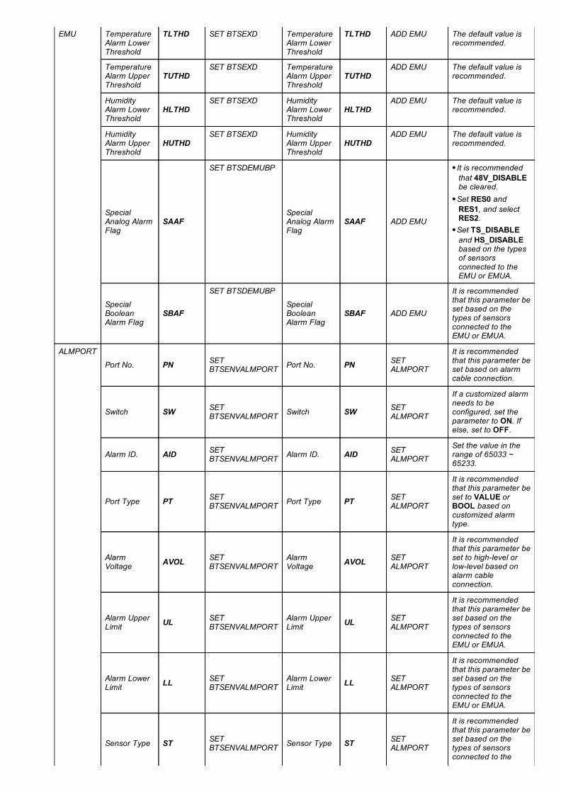
EMU TemperatureAlarm LowerThreshold
TLTHD SET BTSEXD TemperatureAlarm LowerThreshold
TLTHD ADD EMU The default value isrecommended.
TemperatureAlarm UpperThreshold
TUTHDSET BTSEXD Temperature
Alarm UpperThreshold
TUTHDADD EMU The default value is
recommended.
HumidityAlarm LowerThreshold
HLTHDSET BTSEXD Humidity
Alarm LowerThreshold
HLTHDADD EMU The default value is
recommended.
HumidityAlarm UpperThreshold
HUTHDSET BTSEXD Humidity
Alarm UpperThreshold
HUTHDADD EMU The default value is
recommended.
SpecialAnalog AlarmFlag
SAAF
SET BTSDEMUBP
SpecialAnalog AlarmFlag
SAAF ADD EMU
It is recommendedthat 48V_DISABLEbe cleared.Set RES0 andRES1, and selectRES2.Set TS_DISABLEand HS_DISABLEbased on the typesof sensorsconnected to theEMU or EMUA.
SpecialBooleanAlarm Flag
SBAF
SET BTSDEMUBP
SpecialBooleanAlarm Flag
SBAF ADD EMU
It is recommendedthat this parameter beset based on thetypes of sensorsconnected to theEMU or EMUA.
ALMPORT
Port No. PN SETBTSENVALMPORT Port No. PN SET
ALMPORT
It is recommendedthat this parameter beset based on alarmcable connection.
Switch SW SETBTSENVALMPORT Switch SW SET
ALMPORT
If a customized alarmneeds to beconfigured, set theparameter to ON. Ifelse, set to OFF.
Alarm ID. AID SETBTSENVALMPORT Alarm ID. AID SET
ALMPORT
Set the value in therange of 65033 ~65233.
Port Type PT SETBTSENVALMPORT Port Type PT SET
ALMPORT
It is recommendedthat this parameter beset to VALUE orBOOL based oncustomized alarmtype.
AlarmVoltage AVOL SET
BTSENVALMPORTAlarmVoltage AVOL SET
ALMPORT
It is recommendedthat this parameter beset to highlevel orlowlevel based onalarm cableconnection.
Alarm UpperLimit UL SET
BTSENVALMPORTAlarm UpperLimit UL SET
ALMPORT
It is recommendedthat this parameter beset based on thetypes of sensorsconnected to theEMU or EMUA.
Alarm LowerLimit LL SET
BTSENVALMPORTAlarm LowerLimit LL SET
ALMPORT
It is recommendedthat this parameter beset based on thetypes of sensorsconnected to theEMU or EMUA.
Sensor Type ST SETBTSENVALMPORT Sensor Type ST SET
ALMPORT
It is recommendedthat this parameter beset based on thetypes of sensorsconnected to the

EMU or EMUA.
SensorMeasurementUpper Limit
SMUL SETBTSENVALMPORT
SensorMeasurementUpper Limit
SMUL SETALMPORT
It is recommendedthat this parameter beset based on thetypes of sensorsconnected to theEMU or EMUA.
SensorMeasurementLower Limit
SMLL SETBTSENVALMPORT
SensorMeasurementLower Limit
SMLL SETALMPORT
It is recommendedthat this parameter beset based on thetypes of sensorsconnected to theEMU or EMUA.
SensorOutput UpperLimit
SOUL SETBTSENVALMPORT
SensorOutput UpperLimit
SOUL SETALMPORT
It is recommendedthat this parameter beset based on thetypes of sensorsconnected to theEMU or EMUA.
SensorOutput LowerLimit
SOLL SETBTSENVALMPORT
SensorOutput LowerLimit
SOLL SETALMPORT
It is recommendedthat this parameter beset based on thetypes of sensorsconnected to theEMU or EMUA.
The alarm parameters related to the external environment, such as water and smoke sensor parameters must be configuredconsistently for both modes.
If any inconsistency is detected, the base stations of both modes will report the alarm ALM26271 InterSystem Monitoring DeviceParameter Settings Conflict.
To avoid inconsistency, you can perform an MBTS consistency check after configuring parameters. To perform a consistency check onthe CME client, choose MBTS Application > MBTS Check Consistency from the menu bar of a current or planned data area. Toperform a consistency check on the M2000 client, choose CM Express > MBTS Application > MBTS Check Consistency. Fordetailed operations, see section "Checking MBTS Data Consistency" in CME Configuration Management.
7 Reference DocumentsThis chapter lists the reference documents related to monitoring management:
[1] Power Management Feature Parameter Description[2] Base Station Cabinets and Subracks (Including the BBU Subrack) Configuration[3] BTS3900 (Ver.B) Hardware Description[4] BTS3900 (Ver.C) Hardware Description[5] BTS3900 (Ver.D) Hardware Description[6] BTS3900L (Ver.B) Hardware Description[7] BTS3900L (Ver.C) Hardware Description[8] BTS3900L (Ver.D) Hardware Description[9] BTS3900A (Ver.B) Hardware Description[10] BTS3900A (Ver.C) Hardware Description[11] BTS3900A (Ver.D) Hardware Description[12] BTS3900AL (Ver.A) Hardware Description[13] DBS3900 Hardware Description[14] BTS3900C WCDMA Hardware Description[15] BTS3900C (Ver.C) Hardware Description[16] RRUspecific hardware description[17] TP48600AH17B1 User Manual[18] IBBS700D & IBBS700T User Manual[19] Initial Configuration of 3900 Series Base Stations[20] eNodeB Initial Configuration Guide[21] EMU User Guide[22] EMUA User Guide