Huawei Cloud Data Center Converged Resource V100R001C20 .../media/CNBG/Downloads... · The Huawei...
51
Huawei Cloud Data Center Converged Resource Solution V100R001C20 Technical White Paper Issue 02 Date 2015-09-23 HUAWEI TECHNOLOGIES CO., LTD.
Transcript of Huawei Cloud Data Center Converged Resource V100R001C20 .../media/CNBG/Downloads... · The Huawei...
Huawei Cloud Data Center Converged Resource Solution V100R001C20
Technical White Paper
Issue 02
Date 2015-09-23
HUAWEI TECHNOLOGIES CO., LTD.

Issue 02 (2015-09-23) Huawei Proprietary and Confidential
Copyright © Huawei Technologies Co., Ltd.
i
Copyright © Huawei Technologies Co., Ltd. 2015. All rights reserved.
No part of this document may be reproduced or transmitted in any form or by any means without prior written consent of Huawei Technologies Co., Ltd.
Trademarks and Permissions
and other Huawei trademarks are trademarks of Huawei Technologies Co., Ltd.
All other trademarks and trade names mentioned in this document are the property of their respective holders.
Notice
The purchased products, services and features are stipulated by the contract made between Huawei and
the customer. All or part of the products, services and features described in this document may not be
within the purchase scope or the usage scope. Unless otherwise specified in the contract, all statements,
information, and recommendations in this document are provided "AS IS" without warranties, guarantees or representations of any kind, either express or implied.
The information in this document is subject to change without notice. Every effort has been made in the
preparation of this document to ensure accuracy of the contents, but all statements, information, and recommendations in this document do not constitute a warranty of any kind, express or implied.
Huawei Technologies Co., Ltd.
Address: Huawei Industrial Base
Bantian, Longgang
Shenzhen 518129
People's Republic of China
Website: http://e.huawei.com
Distributed Cloud Data Center
Technical White Paper Contents
Issue 02 (2015-09-23) Huawei Proprietary and Confidential
Copyright © Huawei Technologies Co., Ltd.
ii
Contents
1 Overview ................................................................................................................................... 1
1.1 Objectives of the DC2 ............................................................................................................................................ 1
1.2 Overall Architecture of the DC2 ............................................................................................................................. 4
1.3 Logical Deployment of the DC2 ............................................................................................................................. 5
1.4 Logical Concepts of the DC2 .................................................................................................................................. 7
2 Key Features .............................................................................................................................. 8
2.1 VDC ..................................................................................................................................................................... 8
2.1.1 Application Scenarios ......................................................................................................................................... 8
2.1.2 Deployment Architecture .................................................................................................................................... 9
2.1.3 VDC Roles ......................................................................................................................................................... 9
2.1.4 Key Features .....................................................................................................................................................10
2.2 Unified Management ............................................................................................................................................15
2.2.1 Application Scenarios ........................................................................................................................................15
2.2.2 Deployment Architecture ...................................................................................................................................16
2.2.3 Key Features .....................................................................................................................................................17
2.3 OpenStack-based Architecture ..............................................................................................................................22
2.3.1 Application Scenarios ........................................................................................................................................22
2.3.2 Logical Architecture ..........................................................................................................................................22
2.3.3 Key Features .....................................................................................................................................................23
2.4 SDN .....................................................................................................................................................................26
2.4.1 Application Scenarios ........................................................................................................................................26
2.4.2 Deployment Architecture ...................................................................................................................................26
2.4.3 Feature Design...................................................................................................................................................28
2.4.4 Key Features .....................................................................................................................................................29
2.4.5 Device Mappings and Compatibility ..................................................................................................................30
2.5 Backup Management ............................................................................................................................................30
2.5.1 Application Scenarios ........................................................................................................................................30
2.5.2 Deployment Architecture ...................................................................................................................................31
2.5.3 Key Features .....................................................................................................................................................31
2.6 Security Management ...........................................................................................................................................33
2.6.1 Application Scenarios ........................................................................................................................................33
2.6.2 Deployment Architecture ...................................................................................................................................34
Distributed Cloud Data Center
Technical White Paper Contents
Issue 02 (2015-09-23) Huawei Proprietary and Confidential
Copyright © Huawei Technologies Co., Ltd.
iii
2.6.3 Key Features .....................................................................................................................................................35
3 Typical Deployment .............................................................................................................. 40
3.1 Single Data Center Deployment ............................................................................................................................40
3.1.1 Physical Architecture .........................................................................................................................................40
3.1.2 Architecture Overview .......................................................................................................................................41
3.1.3 Component Specifications Recommendations ....................................................................................................42
3.2 Distributed Data Center Deployment.....................................................................................................................43
3.2.1 Physical Architecture .........................................................................................................................................43
3.2.2 Architecture Overview .......................................................................................................................................44
3.2.3 Component Specifications Recommendations ....................................................................................................44
Distributed Cloud Data Center
Technical White Paper Figures
Issue 02 (2015-09-23) Huawei Proprietary and Confidential
Copyright © Huawei Technologies Co., Ltd.
iv
Figures
Figure 1-1 Logical architecture of the DC2 ...................................................................................................... 4
Figure 1-2 OpenStack-based DC2 component deployment ............................................................................... 5
Figure 1-3 Concepts of the DC2 ...................................................................................................................... 7
Figure 2-1 ServiceCenter+OpenStack deployment mode ................................................................................. 9
Figure 2-2 VDC functions ..............................................................................................................................10
Figure 2-3 Template-based rapid service deployment......................................................................................14
Figure 2-4 Unified cloud and non-cloud management .....................................................................................16
Figure 2-5 Heterogeneous virtualization management ....................................................................................16
Figure 2-6 Overall architecture of the DC2 management subsystem.................................................................17
Figure 2-7 DC2 management system components ...........................................................................................18
Figure 2-8 Abnormal fluctuation analysis .......................................................................................................20
Figure 2-9 Storage resource pool QoS analysis ...............................................................................................21
Figure 2-10 Burst traffic analysis ...................................................................................................................21
Figure 2-11 Logical architecture of the converged resource pool .....................................................................22
Figure 2-12 Heterogeneous VMware management solution ............................................................................23
Figure 2-13 Huawei OpenStack management solution for FusionSphere .........................................................24
Figure 2-14 Resource model ..........................................................................................................................25
Figure 2-15 DC2 SDN architecture (OpenStack) .............................................................................................27
Figure 2-16 DC2 network subsystem architecture ...........................................................................................27
Figure 2-17 eBackup architecture ...................................................................................................................31
Figure 2-18 eBackup agentless backup ...........................................................................................................32
Figure 2-19 Security subsystem architecture...................................................................................................34
Figure 2-20 Logical architecture of the vFW ..................................................................................................35
Figure 2-21 Software vFW ............................................................................................................................36
Figure 2-22 Security group ............................................................................................................................36
Figure 2-23 VDC security protection framework ............................................................................................37
Distributed Cloud Data Center
Technical White Paper Figures
Issue 02 (2015-09-23) Huawei Proprietary and Confidential
Copyright © Huawei Technologies Co., Ltd.
v
Figure 2-24 Virtualization antivirus architecture .............................................................................................38
Figure 2-25 TPM reliability computing architecture .......................................................................................39
Figure 3-1 Physical deployment for the flattened two-layer architecture..........................................................41
Figure 3-2 Physical deployment of multiple data centers ................................................................................44
Distributed Cloud Data Center
Technical White Paper Tables
Issue 02 (2015-09-23) Huawei Proprietary and Confidential
Copyright © Huawei Technologies Co., Ltd.
vi
Tables
Table 1-1 Layers in the DC2 ............................................................................................................................ 4
Table 1-2 Components in the DC2 ................................................................................................................... 6
Table 2-1 VDC roles ....................................................................................................................................... 9
Table 2-2 Supported modes for VPC network service provisioning .................................................................29
Table 2-3 Device mappings for carriers ..........................................................................................................30
Table 3-1 Configuration table for the flattened two-layer deployment .............................................................42
Distributed Cloud Data Center
Technical White Paper 1 Overview
Issue 02 (2015-09-23) Huawei Proprietary and Confidential
Copyright © Huawei Technologies Co., Ltd.
1
1 Overview
About This Chapter
The following table lists the main information in this chapter.
Title Content
1.1 Objectives of the DC2 Describes the objectives of the DC
2.
1.2 Overall Architecture of the
DC2
Describes the logical architecture of the DC2.
1.3 Logical Deployment of the
DC2
Describes the logical deployment of the DC2.
1.4 Logical Concepts of the DC2 Describes the logical concepts of the DC
2.
1.1 Objectives of the DC2
To address challenges for data centers and conform to technology development trends,
Huawei launches the Distributed Cloud Data Center (DC2) Solution. The DC
2 Solution is a
solution that is driven by services and supports physically discrete but logically unified
resources, synergy between the cloud and pipes, and service perception.
This solution provides a virtual data center (VDC) platform to support fine-grained IT
operation by using an integrated architecture (converging computing, storage, and network
resources) as the fundamental unit of the resource pool, constructing a software-defined
networking (SDN) service perception network, and managing physically dispersed resources
through automated and intelligent management. The main idea of the DC2 Solution is physical
distribution and logical unification. The DC2 Solution integrates data centers all over the
world into a large server which provides services externally. This solution aims at integrating
multiple data centers to improve IT efficiency for enterprises. Delocalization,
software-defined data center construction, and automation are characteristics of the DC2
Solution. Logical unification has two meanings:
Users manage, schedule, implement O&M for all data centers and resources in the data
centers in a unified manner and implement rights- and domain-based management. To
Distributed Cloud Data Center
Technical White Paper 1 Overview
Issue 02 (2015-09-23) Huawei Proprietary and Confidential
Copyright © Huawei Technologies Co., Ltd.
2
support these capabilities, the DC2 Solution must provide a unified O&M management
platform.
If the distributed cloud data center needs to provide services externally, a unified portal
is required to display services, and a unified process is required to support service provisioning. In this case, the DC
2 Solution must provide a unified service platform.
The DC2 Solution does not aim at improving efficiency and user experience of a single data
center. It regards multiple data centers as one and provides the cloud platform that migrates
cloud resources across data centers, the O&M management system that centrally manages and
schedules resources of multiple data centers, the layer 2 ultra-high bandwidth network, and
software-defined data centers based on cross-data center management, resource scheduling,
and disaster recovery (DR) design. The DC2 is an epoch-making, revolutionary data center
architecture, which brings unprecedented benefits and user experience to customers. The DC2
provides the following benefits:
Reduced total cost of ownership (TCO) and increased return on investment (ROI)
The DC2 adopts virtualization technologies to ensure that software is independent of
hardware and enable the infrastructure with low usage to provide elastic, automated, and
secure computing resource pools. Resources can be allocated to applications on demand.
The Huawei DC2 Solution helps enterprises reduce infrastructure investments and
operation costs by resource consolidation and automation. The distribution technology
logically unifies resources of multiple data centers, improving resource usage and
reducing infrastructure investments. The DC2 provides DR and backup services.
Application availability and resource usage are improved by using the cross-data center
application migration service for load balancing. Improved availability and shortened
downtime help enterprises save intangible costs. Availability of virtual machines (VMs)
can be improved by using the VM migration service. In addition, encapsulation attributes
of VMs and virtual disks and capabilities of obtaining VM status accelerate VM backup and restoration.
Enhanced service agility, quick service rollout, and improved users satisfaction
The DC2 allocates resources on demand through virtualization and supports all-round
management and service automation. Self-service capabilities allow users to apply for
computing, storage, and network resources by themselves on demand. Services are
quickly provisioned and deployed, and the dynamic load balancing function is supported.
Applications can be quickly deployed and created based on templates. The service
modeling function provided by service templates allows users to repeatedly and quickly
create, configure, and deploy applications in the cloud. The application deployment
process is visualized. Applications can be configured between private and public clouds.
The service rollout time is reduced from several days to several minutes. The DC2
provides different SLAs for different applications. The DC2 supports elasticity, which
means that it can automatically scale out or up based on configured scheduling policies.
This ensures that the IT system quickly responds to service changes and converts the data center from a costly center to a valued center.
Fewer IT system management and maintenance resources
The DC2 supports self-service capabilities. Users can apply for services by themselves,
which minimizes dependency on the IT department. Automated workflows are created
based on standard processes, such as event management, problem management, change
management, and release management processes, which improves IT management
efficiency. Centralized O&M, proactive management, and correlation of service
requirements and IT processes eliminate failures and reduce manual operations, so that the O&M efficiency of multiple data centers is improved.
The DC2 provides the following capabilities:
Provides data center as a service (DCaaS) for tenants using VDCs.
Distributed Cloud Data Center
Technical White Paper 1 Overview
Issue 02 (2015-09-23) Huawei Proprietary and Confidential
Copyright © Huawei Technologies Co., Ltd.
3
VDCs are an implement of Software-Defined Data Center (SDDC). Resources of VDCs
come from different resource pools of multiple physical data centers. VDC resources are
classified into computing, storage, network, and bare-metal physical machine resources.
VDC resource capacity is applied for by the VDC Service Manager or specified by the
Domain Service Manager. Resources are provided for users after application approval.
Users can use VDC resources after they submit an application and the application is
approved by the VDC Service Manager. The VDC Service Manager is responsible for
service approval, service template management, service management, resource
configuration, resource provisioning, and self-service O&M. The VDC Service Manager
implements life cycle management for services provided by a VDC. The VDC Service
Manager can define services and publish the services to service catalogs to be applied for
by users, approve users' applications, and cancel published services. Access rights to
VDC resources can be controlled. VDC networks can be defined by the VDC Service
Manager. A VDC is divided into multiple virtual private clouds (VPCs). A VPC includes
multiple subnets and implements security and network management using virtual
firewalls (vFWs) and virtual routers (vRouters). VDCs provide multiple types of
computing, storage, network, and application services at the IaaS layer. The virtual
application (vApp) service supports flexible definition and elastic scaling of software
and applications.
The VDC service provides some self-service O&M capabilities, including viewing VDC
alarms, performance, capacity, and topologies. The VDC service provides resource metering information by VDC, enabling tenants to measure charging information.
Provides cloud infrastructures based on application scenarios.
In different application scenarios, cloud infrastructure requirements vary. The DC2
provides different infrastructures for different application scenarios to meet differentiated
requirements of upper-layer applications and improve infrastructure efficiency and quick delivery capabilities. Cloud infrastructures are provided for four scenarios:
− Standard virtualization scenario
The common application virtualization infrastructure and desktop cloud infrastructure are provided.
− High-throughput scenario
The infrastructure supporting online analytical processing (OLAP) applications is
provided. The infrastructure is optimized in aspects of storage and networks and supports high-performance network connections such as InfiniBand.
− High scalability scenario
The computing and storage convergence solution is adopted to proved rapid scaling capabilities for applications.
− High-performance scenario
To meet requirements of online transaction processing (OLTP) applications and
replace midrange computers with x86 servers, servers adopt multiple Reliability,
Availability, and Serviceability (RAS) technologies to improve reliability. Storage
devices support input/output operations per second (IOPS) in millions, and servers supports response in microseconds.
Supports unified and flexible management of cloud data centers.
Resources of the DC2 come from multiple physical data centers. Diversified resources
make management complex. To simplify management, the DC2 supports unified
management, including:
− Unified management of multiple data centers
Resources from multiple data centers can be centrally accessed and managed.
− Unified management of physical and virtual resources
Distributed Cloud Data Center
Technical White Paper 1 Overview
Issue 02 (2015-09-23) Huawei Proprietary and Confidential
Copyright © Huawei Technologies Co., Ltd.
4
Physical servers, storage devices, and network devices and virtual resources are
managed in a unified manner, and topologies between resources are displayed in a unified view.
− Unified management of multiple virtualization platforms
Various virtualization platforms, such as VMware, Xen, and KVM platforms, are managed in a unified manner.
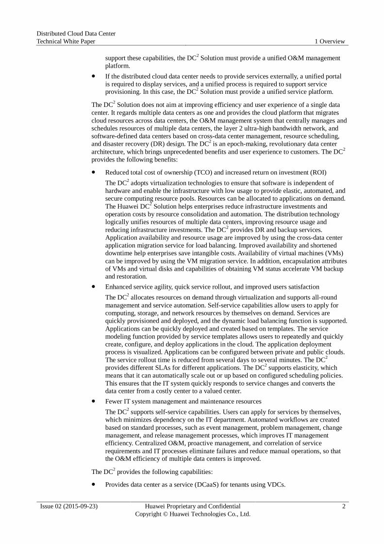
1.2 Overall Architecture of the DC2
Figure 1-1 Logical architecture of the DC2
Figure 1-1 shows the overall architecture of the DC2, which consists of the infrastructure layer,
virtualization layer, and service layer. Each layer provides interfaces to its upper layer.
Table 1-1 Layers in the DC2
Functional Layer Description
Infrastructure layer The infrastructure layer provides capabilities of constructing
computing, storage, and network resource pools. The point of
delivery (POD) is provided for various scenarios to construct virtual
computing, storage, and network resource pools based on physical resources.
Resource pool layer The resource pool layer provides virtual computing, storage, and
network resources. The DC2 provides management capabilities of
converged resource pools, heterogeneous virtualization platforms such as VMware and FusionSphere, and physical resource pools.
Distributed Cloud Data Center
Technical White Paper 1 Overview
Issue 02 (2015-09-23) Huawei Proprietary and Confidential
Copyright © Huawei Technologies Co., Ltd.
5
Functional Layer Description
Service layer The DC2 supports OpenStack and FusionSphere management,
image management, service management, and resource scheduling,
and provides SDN service capabilities, including VPC service capabilities.
Management layer The management layer supports unified management and resource
scheduling for multiple cloud data centers and provides DCaaS
based on VDCs. A VDC provides multiple types of cloud services.
This layer also supports unified O&M of virtual and physical resources.
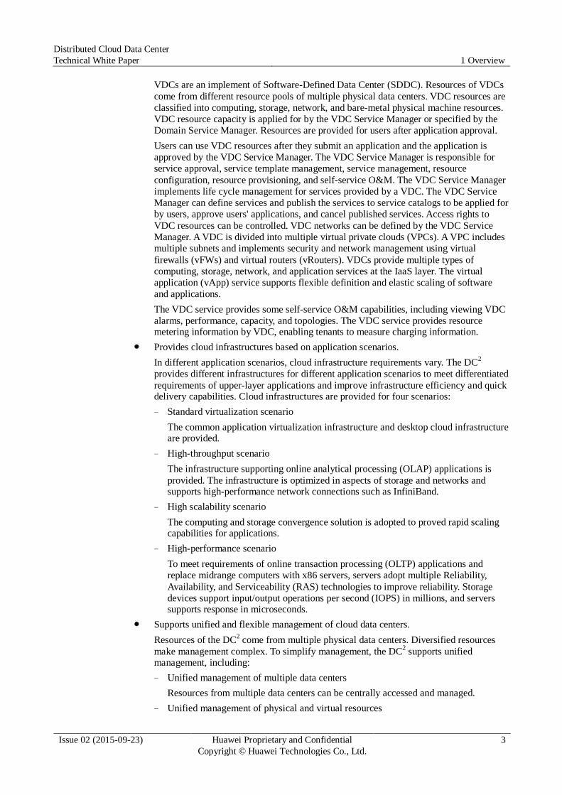
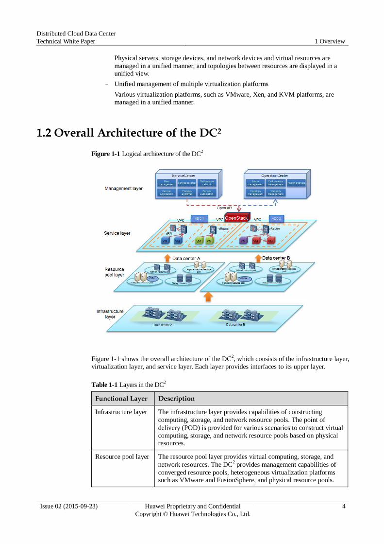
1.3 Logical Deployment of the DC2
The Huawei DC2 Solution adopts OpenStack as the basic cloud management platform. With
the support capabilities of OpenStack for heterogeneous virtual resources, the solution
provides unified management and scheduling of multiple virtualization platforms, and
implements converged resource pool capabilities. Based on OpenStack, a unified O&M
management platform across multiple data centers is constructed, achieving the objectives of
the DC2. Figure 1-2 shows the deployment of the DC
2 components.
Figure 1-2 OpenStack-based DC2 component deployment
Figure 1-2 shows the component connections in the OpenStack architecture. Keystone is
deployed in the domain to implement unified authentication for multiple OpenStack instances.
The OpenStack platform provides native capabilities to adapt to heterogeneous virtualization
platforms, and supports multiple virtualization platforms such as VMware and FusionSphere.

Distributed Cloud Data Center
Technical White Paper 1 Overview
Issue 02 (2015-09-23) Huawei Proprietary and Confidential
Copyright © Huawei Technologies Co., Ltd.
6
Table 1-2 Components in the DC2
Component Function Description
ManageOne ManageOne provides ServiceCenter and OperationCenter.
ServiceCenter: implements unified service orchestration and automatic
management based on cloud and non-cloud resources provided by
resource pools, including customizable heterogeneous and multiple
resource pool policies and orchestration, customizable enterprise service
integration, resource pool management capabilities supplemented by
third-party components, and especially automatic provisioning capabilities for heterogeneous traditional resources.
OperationCenter: implements maintenance based on scenarios and
visualized status, risk, and efficiency analysis for data center services,
and proactively analyzes problems and works with the service center to
implement data center self-optimization and self-healing based on analysis results.
FusionCompute FusionCompute virtualizes and pools computing, storage, and network
resources.
eBackup eBackup is a backup system that is used to back up VM data.
FusionSphere
OpenStack
OpenStack is an open-source cloud management system. OpenStack
consists of multiple components which are decoupled using
Representational State Transfer (REST) interfaces and message queues.
OpenStack can manage heterogeneous virtualization platforms, such as VMware, and UVP. OpenStack consists of the following components:
Nova: virtual computing component
Glance: mirroring component
Cinder: virtual disk component
Neutron: virtual network component
Swift: object storage component
Keystone: authentication component
Ceilometer: monitoring component

Distributed Cloud Data Center
Technical White Paper 1 Overview
Issue 02 (2015-09-23) Huawei Proprietary and Confidential
Copyright © Huawei Technologies Co., Ltd.
7
1.4 Logical Concepts of the DC2
Figure 1-3 Concepts of the DC2
Concepts of the DC2 are as follows:
Domain: indicates the management scope of the data center management system. For the
DC2, a domain includes multiple physical data centers and physical and virtual resources
in the data centers.
Available Zone (AZ): is a logical zone of physical resources (including computing,
storage, and network resources). Devices in an AZ communicate with each other at layer 2. An AZ is an independent failure domain. AZs connect to the same aggregation switch.
VDC: goes across multiple AZs. One VDC includes multiple VPCs.
VPC: adopts network isolation technologies to ensure network security in an AZ. One
VPC belongs only to one AZ.
Host Aggregate: is defined by OpenStack. An Aggregate is a cluster of resources that
have the same properties. Properties are described by metadata. The Scheduler
component selects an Aggregate to allocate resources based on users' requirements. One
Aggregate belongs only to one AZ.
Distributed Cloud Data Center
Technical White Paper 2 Key Features
Issue 02 (2015-09-23) Huawei Proprietary and Confidential
Copyright © Huawei Technologies Co., Ltd.
8
2 Key Features
About This Chapter
The following table lists the main information in this chapter.
Title Content
2.1 VDC Describes the VDC concept and features.
2.2 Unified
Management
Describes the Huawei cloud data center unified management
solution.
2.3
OpenStack-based
Architecture
Describes the Huawei OpenStack cloud management platform.
2.4 SDN Describes the Huawei SDN solution.
2.5 Backup
Management
Describes the backup service.
2.6 Security
Management
Describes the cloud data center security solution.
2.1 VDC
2.1.1 Application Scenarios
VDCs apply to the following scenarios:
In the private cloud of enterprises, leased resources must be independently managed, and
networks must be isolated. Each VDC is an independent management entity that enjoys
self-operation and self-maintenance capabilities. VDCs can be flexibly divided based on
application scenarios of an enterprise.
VDCs are divided based on departments. Each department can independently manage its
resources.
VDCs are divided based on fields, such as the development VDC and testing VDC.
Distributed Cloud Data Center
Technical White Paper 2 Key Features
Issue 02 (2015-09-23) Huawei Proprietary and Confidential
Copyright © Huawei Technologies Co., Ltd.
9
Resources of a VDC come from one or multiple physical data centers. Customers can benefit from capabilities of VDCs, including self-service operation and maintenance and resource isolation management.
2.1.2 Deployment Architecture
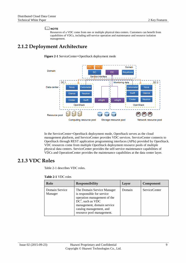
Figure 2-1 ServiceCenter+OpenStack deployment mode
In the ServiceCenter+OpenStack deployment mode, OpenStack serves as the cloud
management platform, and ServiceCenter provides VDC services. ServiceCenter connects to
OpenStack through REST application programming interfaces (APIs) provided by OpenStack.
VDC resources come from multiple OpenStack deployment resource pools of multiple
physical data centers. ServiceCenter provides the self-service maintenance capabilities of
VDCs and OperationCenter provides the maintenance capabilities at the data center layer.
2.1.3 VDC Roles
Table 2-1 describes VDC roles.
Table 2-1 VDC roles
Role Responsibility Layer Component
Domain Service
Manager
The Domain Service Manager
is responsible for service
operation management of the
DC2, such as VDC
management, domain service
catalog management, and resource pool management.
Domain ServiceCenter
Distributed Cloud Data Center
Technical White Paper 2 Key Features
Issue 02 (2015-09-23) Huawei Proprietary and Confidential
Copyright © Huawei Technologies Co., Ltd.
10
Role Responsibility Layer Component
VDC Service
Manager
The VDC Service Manager is
responsible for VDC user
management, VDC service
catalog maintenance, service
application and approval, and VDC self-service maintenance.
VDC ServiceCenter
Service User The Service User is the end user
of VDC services.
App/VDC ServiceCenter
2.1.4 Key Features
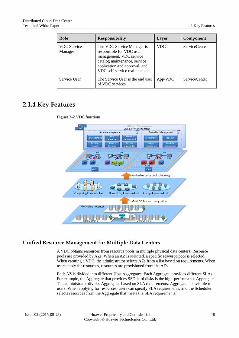
Figure 2-2 VDC functions
Unified Resource Management for Multiple Data Centers
A VDC obtains resources from resource pools in multiple physical data centers. Resource
pools are provided by AZs. When an AZ is selected, a specific resource pool is selected.
When creating a VDC, the administrator selects AZs from a list based on requirements. When
users apply for resources, resources are provisioned from the AZs.
Each AZ is divided into different Host Aggregates. Each Aggregate provides different SLAs.
For example, the Aggregate that provides SSD hard disks is the high-performance Aggregate.
The administrator divides Aggregates based on SLA requirements. Aggregate is invisible to
users. When applying for resources, users can specify SLA requirements, and the Scheduler
selects resources from the Aggregate that meets the SLA requirements.
Distributed Cloud Data Center
Technical White Paper 2 Key Features
Issue 02 (2015-09-23) Huawei Proprietary and Confidential
Copyright © Huawei Technologies Co., Ltd.
11
VDC Isolation
VDCs provide management, network, and resource isolation capabilities.
Management isolation
After logging in to a VDC, users can apply for services provided by the VDC and use the
services after their applications are approved by the VDC Service Manager. Each VDC
provides independent user management, service management, template management,
service catalog management, capacity management, O&M management, and approval
process management capabilities. The VDC Service Manager manages the local VDC
only without affecting management of other VDCs. This ensures isolated VDC management.
Network isolation
The VDC network topology can be self-defined, which includes multiple security
domains. Security domains are isolated from each other using VLANs or VXLANs.
Virtual resources (such as VMs) are included in security domains. External users must
access resources in security domains through vFWs. ACL, application specific packet
filter (ASPF), and NAT rules set on vFWs ensure secure access. Different security
domains communicate with each other through the Internet Protocol Security virtual private network (IPsec VPN), ensuring network data security.
Resource isolation
Resources include virtual resources (such as VMs and virtual disks), service templates,
and software libraries. Resources of each VDC are independently managed. For example,
VMs and vFWs of a VDC can be managed only in the VDC. VDCs do not share
resources. Only the user who owns a certain resource can view information about the
resource and operate the resource in a VDC, such as starting and stopping VMs and
expanding capacity. Users of other VDCs cannot view information about the resource and operate the resource.
Quota Management
VDC resources can be controlled based on quota. The quota is specified by an applicant when
a VDC is created and approved by the Domain Service Manager. The quota can also be
specified by the Domain Service Manager when the Domain Service Manager creates a VDC.
Quotas include the numbers of vCPUs VLANs, VPCs, subnets, and VMs, memory capacity,
and network bandwidth. If users apply for resources that exceed the quota, the VDC
automatically rejects the application. The quota usage is displayed, facilitating capacity
control for the VDC Service Manager.
User Management
Each VDC supports independent user management. The VDC Service Manager can assign
VDC access rights to users. After being granted rights, users can log in to the VDC and apply
for services of the VDC. A user can be granted rights to access multiple VDCs.
Service Management
The VDC Service Manager manages service catalogs and service life cycles. The VDC
Service Manager can define service catalogs which include services that have been published
and can be subscribed to by users. The VDC Service Manager defines services, including the
service name, description, specifications, and properties, and then publishes the services to a
service catalog. VDC users can browse the service catalog and apply for services from the
Distributed Cloud Data Center
Technical White Paper 2 Key Features
Issue 02 (2015-09-23) Huawei Proprietary and Confidential
Copyright © Huawei Technologies Co., Ltd.
12
catalog. The VDC Service Manager can cancel services that are not provided anymore. The
canceled services are not displayed in the service catalog and cannot be applied for by users.
Template Management
VDCs provide multiple types of service templates that help the VDC Service Manager to
quickly define new services. Service configuration specifications and default values can be
defined in service templates. Service templates provided by VDCs include VM templates and
vApp templates. The service templates enable the VDC Service Manager to quickly create
and deploy services.
Service Automation
Service automation supports automatic service provisioning and rollout. After users apply for
services from service catalogs and their applications are approved, the service automation
engine invokes related service implementation processes based on subscribed services.
Service processes are implemented by the internal business process management (BPM)
engine. The BPM engine automatically invokes REST interfaces of virtualization systems and
ensures the process implementation sequence and results. The system provides default
services processes covering VM, virtual disk, and virtual network device services. The
administrator can define new service provisioning processes to meet new service
requirements.
Self-service Network Management
VDC self-service network management is implemented by the basic capabilities provided by
the virtualization layer. The following items support self-service management:
VPC
Users can define VPCs in a VDC. Each VPC includes multiple subnets. VPCs include
three types, direct network, internal network, and routed network. A vRouter can be
defined for a routed network VPC to serve as the assess point of the VPC. Users can also
define virtual network components, such as vFWs and vLBs, in a routed network VPC. Security policies can be set on vFWs to control access to resources in VPCs.
Subnet
A security domain can be divided into multiple subnets. Subnets are isolated from each other at layer 2 using VLANs. Users can manage IP addresses of subnets.
VDC network topology
Users can view VDC network topologies. The network topology displays connections
between security domains in a VDC, network resources and subnets in each security
domain, and vApp and VM resources of each subnet. The virtual network topology
displays mapping relationships between physical and virtual resources, such as the mapping relationships between vFWs and physical firewalls.
VDC Metering Management
The VDC metering capability includes the metering of the CPU, memory, disk, VPC, elastic
IP address, security group, and VM resource quotas. The VDC quota metering feature
provides metering data for the service settlement. Administrators and tenants use the metering
data to perform the offline charging and settlement. VDC quotas that can be metered include
the numbers of vCPUs, elastic IP addresses, VPCs, VMs, and security groups, memory
capacity, and disk space. The VDC quota metering feature provides functions such as
querying VDC metering statistics of a specified period and exporting metering statistics.
Distributed Cloud Data Center
Technical White Paper 2 Key Features
Issue 02 (2015-09-23) Huawei Proprietary and Confidential
Copyright © Huawei Technologies Co., Ltd.
13
Self-service O&M Management Capacity management
The VDC Service Manager can view resource usage and capacity usage of a VDC.
Usage of CPUs, memory, disks, and bandwidth can be queried. The VDC Service
Manager can set capacity thresholds. When the resource usage exceeds the threshold, the system reports an alarm.
Performance management
The VDC Service Manager can view the performance data of resources in a VDC on
OperationCenter, including performance indicators such as CPU, memory, disks, and networks.
Preset Services
After logging in to the VDC self-service portal, users can view multiple types of preset cloud
services in service catalogs, including:
Cloud host service
The cloud host service enables users to use cloud hosts like using local PCs. When
applying for the cloud host service on the self-service portal, users can select VM
templates and specify VM specifications (such as storage and memory capacity) and
submit the application. Users can use log in to cloud hosts using assigned IP addresses
after their applications are approved. Users can start, stop, hibernate, and wake up cloud
hosts and expand or reduce capacity of cloud hosts.
Physical server service
Users can apply for the physical server service online. During application, users can
specify server specifications and OS types. After the application is approved, OSs can be
installed in the preboot execution environment (PXE) mode. Users can log in to physical
servers and perform related service operations such as software installation.
EBS service
Elastic Block Storage (EBS) provides block storage services to VMs. The EBS service
enables users to expand storage space on demand. The OSs on user VMs access block
storage space by volume. The EBS service allows users to expand or reduce block storage capacity.
Elastic IP address
The elastic public IP address is also called the elastic IP address service. This service
configures one-to-one mapping between the private IP address and the public IP address
for users' requested VMs or physical servers. Users can access VMs or physical servers in a data center using public IP addresses.
vApp service
The vApp service includes the following sub-features:
− Rapid vApp deployment
Application templates can be prepared for common applications and middleware
(such as LAMP, WebSphere, and Hadoop). Application templates allow users to
quickly create and deploy applications. The DC2 provides convenient application
making methods and the rapid application deployment service. Administrators or
application developers can make VM templates and upload application software
packages on the self-service portal based on requirements. Applications are
automatically rapidly deployed using VM templates, application templates, and the user-defined orchestration function.
Distributed Cloud Data Center
Technical White Paper 2 Key Features
Issue 02 (2015-09-23) Huawei Proprietary and Confidential
Copyright © Huawei Technologies Co., Ltd.
14
Users can create their own VM templates and application templates. The templates
can be made by considering computing, storage, network, and elasticity factors. Users can implement rapid and automatic application deployment based on templates.
After the system receives an application deployment request, the system
automatically creates VMs, installs application software on VMs, and creates
dependency and networks between application software based on resource definitions in application templates.
Users can specify scaling policies. The system automatically triggers capacity
expansion and reduction for scaling groups based on user-defined monitoring
conditions. The system adjusts resources in scaling groups to ensure stable running of
applications.
In the OpenStack scenario, applications can be deployed only using images but cannot be deployed using software packages.
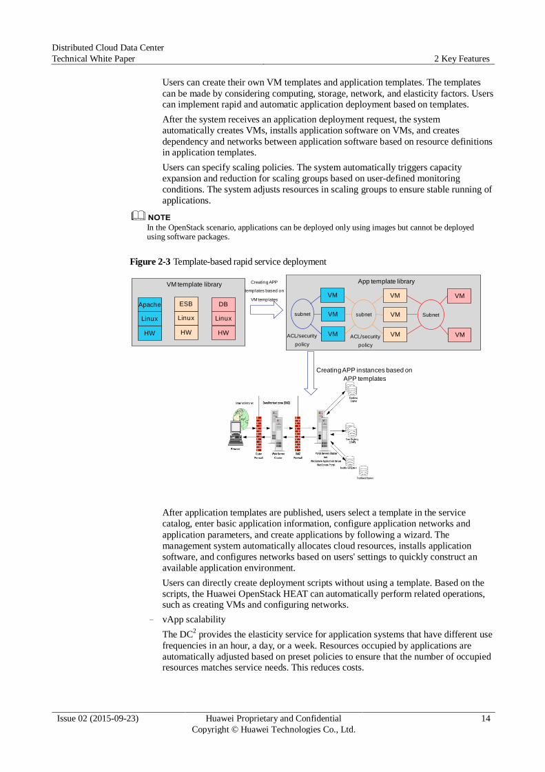
Figure 2-3 Template-based rapid service deployment
After application templates are published, users select a template in the service
catalog, enter basic application information, configure application networks and
application parameters, and create applications by following a wizard. The
management system automatically allocates cloud resources, installs application
software, and configures networks based on users' settings to quickly construct an
available application environment.
Users can directly create deployment scripts without using a template. Based on the
scripts, the Huawei OpenStack HEAT can automatically perform related operations, such as creating VMs and configuring networks.
− vApp scalability
The DC2 provides the elasticity service for application systems that have different use
frequencies in an hour, a day, or a week. Resources occupied by applications are
automatically adjusted based on preset policies to ensure that the number of occupied resources matches service needs. This reduces costs.
VM
subnetVM
VM
VM
VM
VM
subnet
HW
Linux
Apache
HW
Linux
DB
Subnet
VM
VMHW
Linux
ESB
VM template library
ACL/security
policy
ACL/security
policy
App template library
Creating APP instances based on
APP templates
Creating APP
templates based on
VM templates
Distributed Cloud Data Center
Technical White Paper 2 Key Features
Issue 02 (2015-09-23) Huawei Proprietary and Confidential
Copyright © Huawei Technologies Co., Ltd.
15
Users can create scaling groups in applications and set scaling policies for scaling
groups. A scaling group contains VMs to which the same scaling policies are applied.
The system monitors indicators of VMs, such as CPU usage and memory usage,
based on user-defined scaling policies to implement scalability. Scalability refers to
creating or deleting, starting or stopping, and waking up or hibernating VMs. The
scalability service aims at controlling resources used by scaling groups by controlling VM resources and controlling resources occupied by applications.
Users can set scaling policies for a single application and set inter-application
resource sharing policies for multiple applications.
An inter-group policy is applied to enable resource sharing among different scaling
groups and manage the resource allocation and preemption among scaling groups in
one resource pool, thereby ensuring the proper operation of the entire resource pool.
Applications that are not in scaling groups or do not preempt resources are not
managed by the inter-group policy. The inter-group resource sharing policy can work
with scaling policies of scaling groups to meet requirements of scalability between
multiple applications. Users need to set inter-group resource sharing policies,
reserved resources of resource pools where the inter-group resource sharing policies
are applied, and resources used by scaling groups of different applications. When the
system detects that the resources in resource pools are fewer than reserved resources,
the system reclaims resources from scaling groups of applications with a low priority to ensure that applications with a high priority can be allocated with resources.
Inter-group policies can be also used with scheduled tasks for time-based resource
reuse purposes. Importance and required resources of applications at different time
points are different. Users can define scheduled task policies to adjust the limit of
used resources and priority of scaling groups in different time periods to implement time-based resource reuse.
2.2 Unified Management
2.2.1 Application Scenarios
The unified management capabilities of the DC2 apply to the following scenarios:
Unified multi-data center management
Multiple physical data centers must be managed in a unified manner.
Unified physical and virtual resource management
Physical and virtual resources of a data center must be managed in a unified manner. For
example, physical and virtual resources are centrally monitored and managed in a topology.
Unified heterogeneous resource pool management
Heterogeneous virtualization platforms in a data center must be managed in a unified
manner. For example, the vSphere and Huawei UVP virtualization platforms are managed in a unified manner.
Distributed Cloud Data Center
Technical White Paper 2 Key Features
Issue 02 (2015-09-23) Huawei Proprietary and Confidential
Copyright © Huawei Technologies Co., Ltd.
16
2.2.2 Deployment Architecture
Unified Cloud and Non-Cloud Management
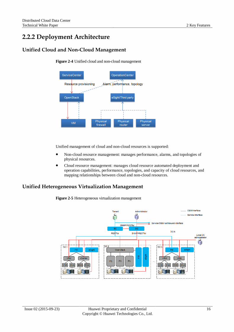
Figure 2-4 Unified cloud and non-cloud management
Unified management of cloud and non-cloud resources is supported:
Non-cloud resource management: manages performance, alarms, and topologies of physical resources.
Cloud resource management: manages cloud resource automated deployment and
operation capabilities, performance, topologies, and capacity of cloud resources, and
mapping relationships between cloud and non-cloud resources.
Unified Heterogeneous Virtualization Management
Figure 2-5 Heterogeneous virtualization management
Distributed Cloud Data Center
Technical White Paper 2 Key Features
Issue 02 (2015-09-23) Huawei Proprietary and Confidential
Copyright © Huawei Technologies Co., Ltd.
17
Different heterogeneous virtualization modes are adopted for different solutions.
Huawei FusionSphere OpenStack supports VMware vSphere, and the Huawei UVP connects
to the OpenStack management platform and provides the unified resource provisioning and
management capabilities of heterogeneous resource pools. vSphere adopts the OpenStack
access solution provided by VMware. Similar to the access mode of VMware, Huawei
FusionSphere connects to the VRM by adding plug-ins to Nova and Cinder. OpenStack
implements heterogeneous virtualization, simplifies the cloud data center management
architecture, and avoids management silos.
2.2.3 Key Features
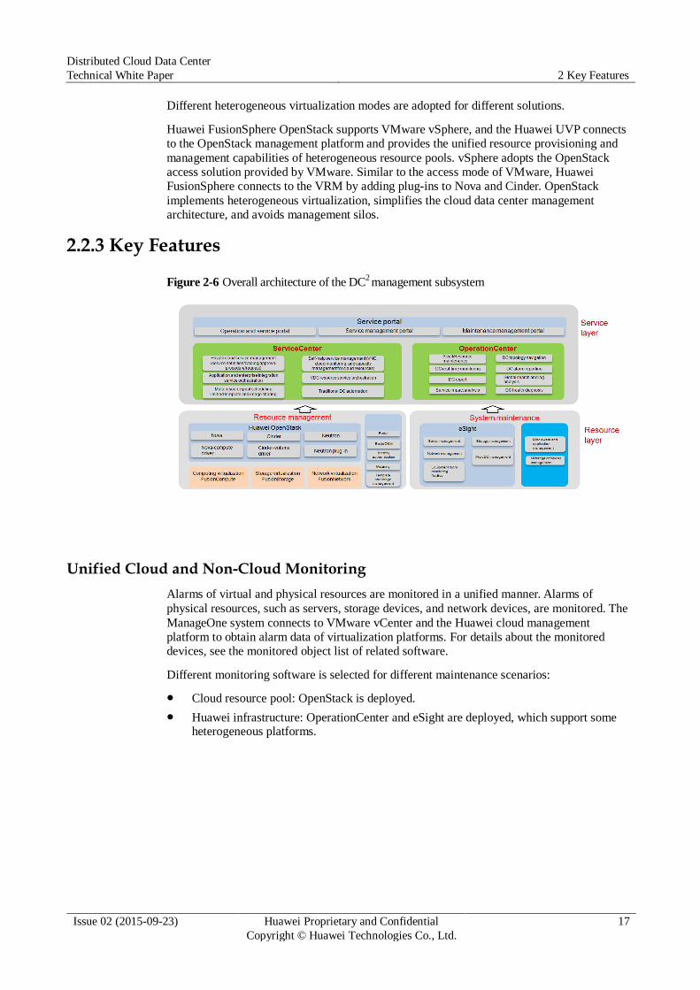
Figure 2-6 Overall architecture of the DC2 management subsystem
Unified Cloud and Non-Cloud Monitoring
Alarms of virtual and physical resources are monitored in a unified manner. Alarms of
physical resources, such as servers, storage devices, and network devices, are monitored. The
ManageOne system connects to VMware vCenter and the Huawei cloud management
platform to obtain alarm data of virtualization platforms. For details about the monitored
devices, see the monitored object list of related software.
Different monitoring software is selected for different maintenance scenarios:
Cloud resource pool: OpenStack is deployed.
Huawei infrastructure: OperationCenter and eSight are deployed, which support some heterogeneous platforms.
Distributed Cloud Data Center
Technical White Paper 2 Key Features
Issue 02 (2015-09-23) Huawei Proprietary and Confidential
Copyright © Huawei Technologies Co., Ltd.
18
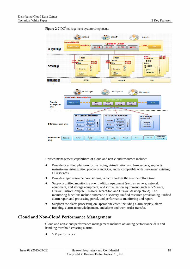
Figure 2-7 DC2 management system components
Unified management capabilities of cloud and non-cloud resources include:
Provides a unified platform for managing virtualization and bare servers, supports
mainstream virtualization products and OSs, and is compatible with customers' existing IT resources.
Provides rapid resource provisioning, which shortens the service rollout time.
Supports unified monitoring over tradition equipment (such as servers, network
equipment, and storage equipment) and virtualization equipment (such as VMware,
Huawei FusionCompute, Huawei OceanStor, and Huawei desktop cloud). The
monitoring functions include automatic discovery, unified resource provisioning, unified alarm report and processing portal, and performance monitoring and report.
Supports the alarm processing on OperationCenter, including alarm display, alarm masking, alarm acknowledgement, and alarm and work order transfer.
Cloud and Non-Cloud Performance Management
Cloud and non-cloud performance management includes obtaining performance data and
handling threshold crossing alarms.
VM performance
Distributed Cloud Data Center
Technical White Paper 2 Key Features
Issue 02 (2015-09-23) Huawei Proprietary and Confidential
Copyright © Huawei Technologies Co., Ltd.
19
The ManageOne system connects to vCenter to monitor VM performance indicators,
including the CPU usage, memory usage, network bandwidth, and disk I/O.
Physical resource performance
Performance data of physical resources is obtained from eSight or third-party monitoring
components. Monitored physical resources include physical servers, network devices
(including switches, routers, and firewalls), and storage devices. Monitoring indicators
include the CPU usage, memory usage, and network bandwidth, which vary according to
device types. Monitoring software sends monitoring results to OperationCenter, and
OperationCenter centrally displays the results. OperationCenter can display Top N performance indicators of servers, storage devices, and network devices.
Threshold crossing alarms
The administrator can define performance thresholds. When performance indicator
values of monitored objects exceed the threshold, the system generates an alarm, prompting the administrator to handle performance risks.
Cloud and Non-Cloud Topology Management
Cloud and non-cloud topology management provides the following functions:
Physical topology management
Physical resources and connections between physical resources are automatically
detected. Third-party components automatically detect topologies, and OperationCenter
integrates topologies of third-party components and displays the topologies in a unified manner.
Virtual topology management
Topological relationships between virtualization components in a VDC are displayed.
The administrator can define virtualization components and their connections, so virtual
topologies are displayed based on definitions.
Topological relationship mapping
Virtual networks are overlaid on physical networks. Therefore, virtual network devices have mapping relationships with physical network devices.
Cloud Resource Capacity Management
OperationCenter obtains cloud resource data from OpenStack. OperationCenter centrally
displays the cloud resource usage, including usage of vCPUs, memory, disk space, and
bandwidth. Resource capacity can be displayed based on physical data centers and VDCs.
Heterogeneous Virtualization Platform Management
Huawei FusionSphere OpenStack provides the heterogeneous virtualization platform
management capabilities.
The OpenStack architecture provides native capabilities to support multiple types of
virtualization platforms. Currently, Huawei FusionSphere OpenStack can connect to the UVP
and VMware platforms through interfaces.
Data Center Health Check
OperationCenter provides proactive maintenance capabilities in three aspects: health
assessment, risk assessment, and efficiency assessment. These capabilities are used to assess the health status of a running data center based on the analysis and handling (including

Distributed Cloud Data Center
Technical White Paper 2 Key Features
Issue 02 (2015-09-23) Huawei Proprietary and Confidential
Copyright © Huawei Technologies Co., Ltd.
20
predictions, dynamic thresholds, and points) of data center infrastructure alarms and
performance monitoring data, thereby generating alarms when faults occur to reduce the
maintenance risks.
Health assessment
The health assessment comprehensively assesses the running status of a maintenance
object from three dimensions: workload, abnormal fluctuation, and alarm. The health
assessment dynamically determines the abnormal fluctuation of indicators based on the
historical behavior of indicators, resolving the time-based adjustment failures of traditional static thresholds.
The health assessment implements the analysis in two aspects, abnormality (long term)
and fluctuation (short term), comprehensively measuring the stability of indicators. The
health analysis can accurately identify abnormalities. The dynamic configuration is
supported, such as the configuration of historical duration and sensitivity. The health
abnormal fluctuation algorithm adopts the time sequence processing in the sliding
window to select a time sequence, and the amplitude of thresholds can be changed
dynamically. The result can be obtained by adding or subtracting K times of the standard deviation based on the average value, and the K value can be set flexibly as required.
Figure 2-8 Abnormal fluctuation analysis
Risk assessment
The risk assessment comprehensively assesses the capacity and performance risks of a
maintenance object from three dimensions: remaining time, remaining capacity, and
pressure. The key difficulties of the risk assessment are the accuracy of the remaining
time prediction and the pressure measurement method. Huawei supports the combination
of weekly prediction and daily prediction for the remaining time prediction. The
prediction error is less than one week. As for the pressure measurement of an object, the assessment involves two factors, time and amplitude, based on points.
For the weekly prediction, the average value of busy hours during workdays in a week is
used. Busy hours in the latest four weeks can be adopted for the prediction. The daily
prediction provides finer-grained prediction based on the result of the weekly prediction.
The time when the maximum value (100%) is reached in a duration of N+1 weeks is
used as the prediction result. If workday D is M days later than the current time, the
remaining time is (N x 7 + M) days. If the number of sampling days is too large, the
daily prediction may cause prediction curve distortion (such as non-monotone). By the
combination of weekly prediction and daily prediction, prediction distortion can be
reduced and the prediction result can be accurate to day.
The pressure algorithm adopts the area points. The percentage of the area that exceeds
the pressure line in the entire pressure area is calculated every hour. The pressure of an
object is displayed in a 24/7 heat map. The pressure algorithm adopts the point mode and
also considers the pressure duration and amplitude, thereby comprehensively reflecting the pressure of an object.
Efficiency assessment
Distributed Cloud Data Center
Technical White Paper 2 Key Features
Issue 02 (2015-09-23) Huawei Proprietary and Confidential
Copyright © Huawei Technologies Co., Ltd.
21
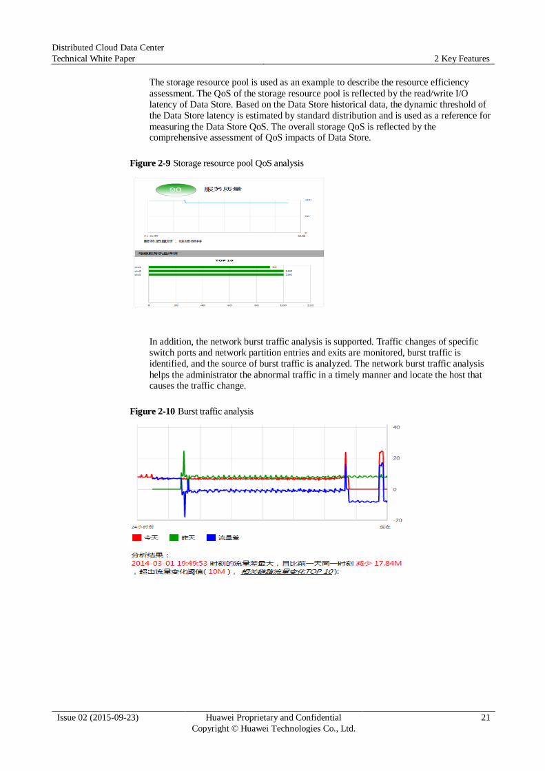
The storage resource pool is used as an example to describe the resource efficiency
assessment. The QoS of the storage resource pool is reflected by the read/write I/O
latency of Data Store. Based on the Data Store historical data, the dynamic threshold of
the Data Store latency is estimated by standard distribution and is used as a reference for
measuring the Data Store QoS. The overall storage QoS is reflected by the comprehensive assessment of QoS impacts of Data Store.
Figure 2-9 Storage resource pool QoS analysis
In addition, the network burst traffic analysis is supported. Traffic changes of specific
switch ports and network partition entries and exits are monitored, burst traffic is
identified, and the source of burst traffic is analyzed. The network burst traffic analysis
helps the administrator the abnormal traffic in a timely manner and locate the host that causes the traffic change.
Figure 2-10 Burst traffic analysis
Distributed Cloud Data Center
Technical White Paper 2 Key Features
Issue 02 (2015-09-23) Huawei Proprietary and Confidential
Copyright © Huawei Technologies Co., Ltd.
22
2.3 OpenStack-based Architecture
2.3.1 Application Scenarios
The Huawei cloud management platform implements open architecture based on OpenStack.
As the most active open-source project, OpenStack involves the participation of multiple
vendors. OpenStack can be expanded in plug-in mode, supporting third-party devices and
heterogeneous virtualization platforms. In this mode, customers are not bound to the
infrastructure and virtualization platform of a single vendor, and the open northbound APIs of
OpenStack can be easily invoked and managed by third parties. Based on OpenStack
architecture, Huawei implements the support for converged resource pools. Converged
resource pools apply to the following scenarios:
Hybrid deployment of heterogeneous virtualization platforms
Unified management of heterogeneous virtualization platforms is supported. Resource
provisioning capabilities are provided for heterogeneous resource pools such as Huawei
FusionSphere and VMware.
Hybrid management of physical servers and VMs
In some cloud data centers, high-performance and high IOPS applications (such as
databases) are deployed on physical servers, and common-performance applications (such as middleware applications) are deployed on VMs.
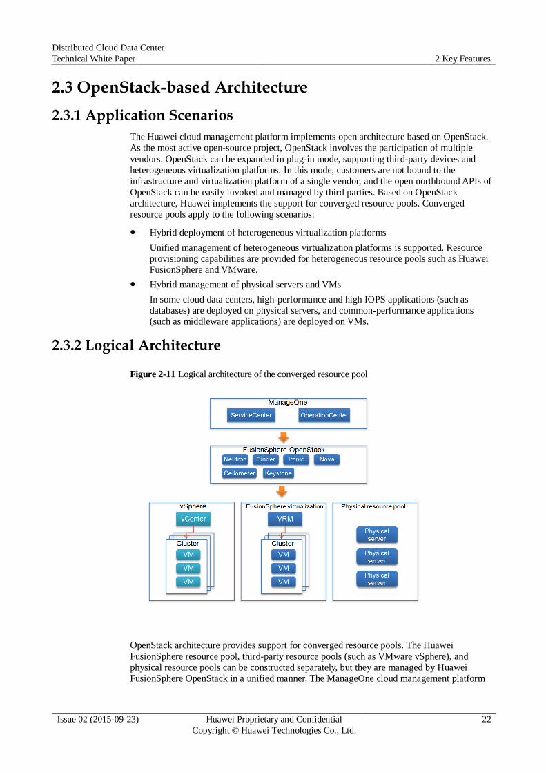
2.3.2 Logical Architecture
Figure 2-11 Logical architecture of the converged resource pool
OpenStack architecture provides support for converged resource pools. The Huawei
FusionSphere resource pool, third-party resource pools (such as VMware vSphere), and
physical resource pools can be constructed separately, but they are managed by Huawei FusionSphere OpenStack in a unified manner. The ManageOne cloud management platform
Distributed Cloud Data Center
Technical White Paper 2 Key Features
Issue 02 (2015-09-23) Huawei Proprietary and Confidential
Copyright © Huawei Technologies Co., Ltd.
23
provides unified monitoring and resource provisioning capabilities for heterogeneous resource
pools. The selection of resources is determined according to the resource quality of service
(QoS) requirements and resource types (such as vSphere or FusionSphere VM).
2.3.3 Key Features
Unified Management of Heterogeneous Resource Pools
The Huawei FusionSphere solution provides unified management of heterogeneous
virtualization resource pools. The heterogeneous management capabilities of Huawei
OpenStack provide management of the VMware vSphere virtualization resource pool and the
Huawei FusionSphere virtualization resource pool. Different virtualization platforms are
converged into a resource pool that features physical distribution and logical unification.
Huawei OpenStack provides OpenStack-based northbound APIs, facilitating management
operations such as resource creation and deletion.
The ManageOne cloud management platform supports heterogeneous virtualization resource
management in a VDC. By selecting a resource pool type, tenants can apply for the creation
of different VMs and manage different virtualization platforms.
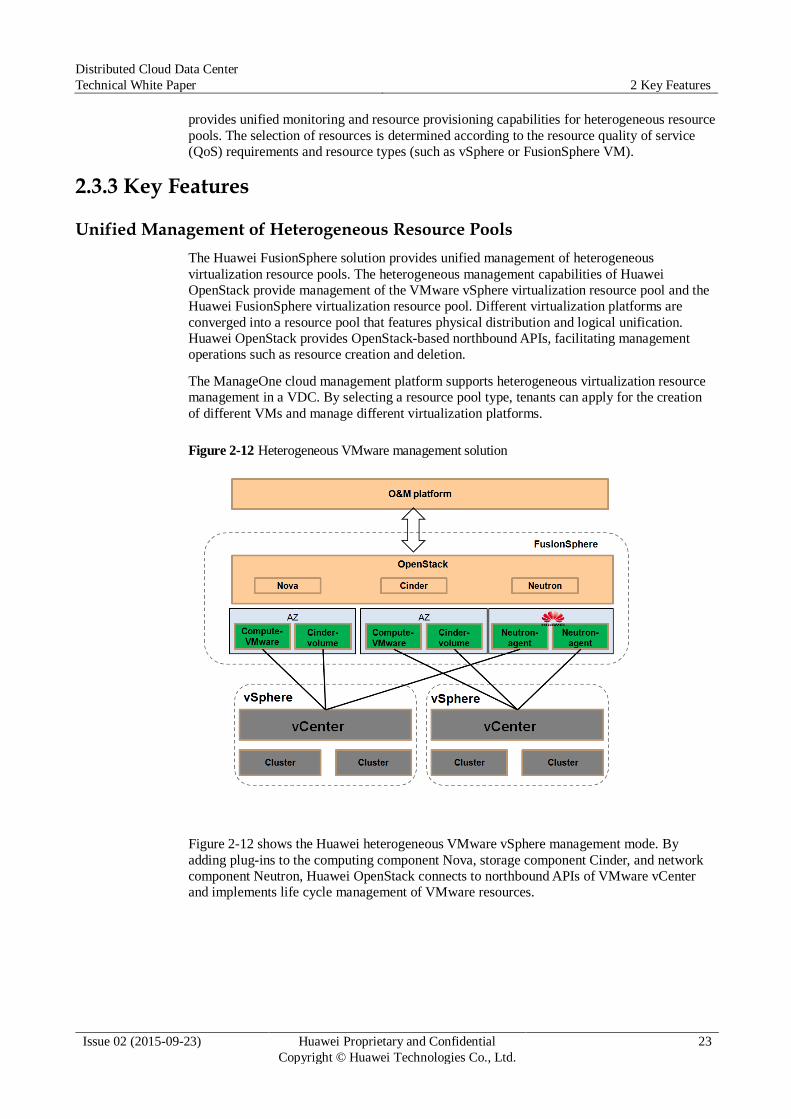
Figure 2-12 Heterogeneous VMware management solution
Figure 2-12 shows the Huawei heterogeneous VMware vSphere management mode. By
adding plug-ins to the computing component Nova, storage component Cinder, and network
component Neutron, Huawei OpenStack connects to northbound APIs of VMware vCenter
and implements life cycle management of VMware resources.
Distributed Cloud Data Center
Technical White Paper 2 Key Features
Issue 02 (2015-09-23) Huawei Proprietary and Confidential
Copyright © Huawei Technologies Co., Ltd.
24
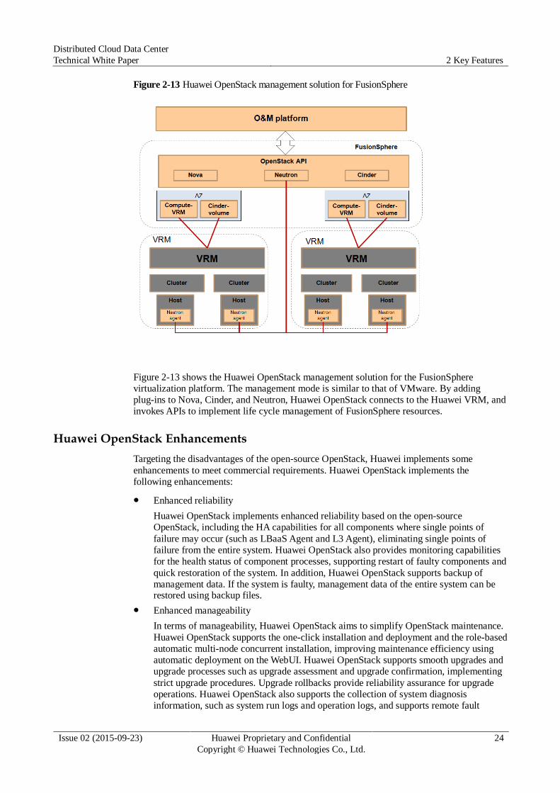
Figure 2-13 Huawei OpenStack management solution for FusionSphere
Figure 2-13 shows the Huawei OpenStack management solution for the FusionSphere
virtualization platform. The management mode is similar to that of VMware. By adding
plug-ins to Nova, Cinder, and Neutron, Huawei OpenStack connects to the Huawei VRM, and
invokes APIs to implement life cycle management of FusionSphere resources.
Huawei OpenStack Enhancements
Targeting the disadvantages of the open-source OpenStack, Huawei implements some
enhancements to meet commercial requirements. Huawei OpenStack implements the
following enhancements:
Enhanced reliability
Huawei OpenStack implements enhanced reliability based on the open-source
OpenStack, including the HA capabilities for all components where single points of
failure may occur (such as LBaaS Agent and L3 Agent), eliminating single points of
failure from the entire system. Huawei OpenStack also provides monitoring capabilities
for the health status of component processes, supporting restart of faulty components and
quick restoration of the system. In addition, Huawei OpenStack supports backup of
management data. If the system is faulty, management data of the entire system can be restored using backup files.
Enhanced manageability
In terms of manageability, Huawei OpenStack aims to simplify OpenStack maintenance.
Huawei OpenStack supports the one-click installation and deployment and the role-based
automatic multi-node concurrent installation, improving maintenance efficiency using
automatic deployment on the WebUI. Huawei OpenStack supports smooth upgrades and
upgrade processes such as upgrade assessment and upgrade confirmation, implementing
strict upgrade procedures. Upgrade rollbacks provide reliability assurance for upgrade
operations. Huawei OpenStack also supports the collection of system diagnosis information, such as system run logs and operation logs, and supports remote fault

Distributed Cloud Data Center
Technical White Paper 2 Key Features
Issue 02 (2015-09-23) Huawei Proprietary and Confidential
Copyright © Huawei Technologies Co., Ltd.
25
locating. Huawei OpenStack supports refined monitoring and fault alarming capabilities,
and provides multiple monitoring indicators.
Enhanced support for infrastructures by adding plug-ins
Expansions aim to enhance the usability, reliability, compatibility, and automatic
management level of the standard OpenStack, and provide an OpenStack-based cloud
platform solution for commercial use. All expansions and enhancements are
implemented based on the native standard plug-ins and driving mechanisms of
OpenStack. The OpenStack main code is not modified. Drivers from other vendors can
be seamlessly integrated with the Huawei OpenStack solution for commercial use,
ensuring the openness of OpenStack. The enhanced functions can be easily migrated to
OpenStack of a later version when OpenStack upgrades.
Resource QoS Management
Resource QoS management aims to meet customers' requirements on the resource QoS, and
provide services of a balance between cost-effectiveness and QoS. To implement resource
QoS management, SLAs must be clearly defined for resources. An SLA is an agreement
between the service provider and customers to ensure the performance and reliability of
services to be provided at certain costs. SLAs are provided to ensure a balance between QoS
and costs.
Figure 2-14 Resource model
The DC2 supports the QoS tag group defining for resources. Multiple tags can be added to a
resource. The following table provides an example.
Host Group Tag
Host group 1 (Aggregate 1) SSD = true, Reliability = high, GPU = true
Host group 2 (Aggregate 2) Reliability = medium, Security = true

Distributed Cloud Data Center
Technical White Paper 2 Key Features
Issue 02 (2015-09-23) Huawei Proprietary and Confidential
Copyright © Huawei Technologies Co., Ltd.
26
Multiple tags are defined for the two host groups to describe the QoS features of the host
cluster. For resource selection, the administrator can define flavor tags. The flavor tags
include resource QoS tags. For example, the high-reliability flavor can be defined as the
selection of VMs in host group 1 and the high-security flavor can be defined as the selection
of VMs in host group 2. During VM creation, users can select the QoS according to the flavor
tags. For example, if a user requires a high-security VM, the scheduling algorithm creates a
VM in host group 2 for the user.
Physical Server Management
Some data center applications cannot run on VMs, such as the Oracle database that is
sensitive to performance. To meet the requirements of these applications, physical server
resource pools must be built for data centers. Huawei FusionSphere supports unified
management of physical servers, and can obtain the monitoring, alarm, and performance data
of physical servers.
2.4 SDN
2.4.1 Application Scenarios
SDN is new network architecture that provides programmable networks. The SDN
architecture provides maximum network control flexibility. With the development of the
mobile Internet and big data technologies, more and more IT services are migrated to data
centers. Network as a service (NaaS) is a basic IT service in the cloud data center. Tenants can
flexibly apply for virtual network resources to meet IT service requirements.
The DC2 supports the layer 2 VLAN automation, and hardware devices must be configured
manually. In the cloud data center, SDN applies to the following scenarios:
Network automation
Northbound APIs are provided for upper-layer management software, so that upper-layer
management software can invoke APIs to implement network automation and provide real-time network services. This ensures quick service rollout.
Flexible service network
Based on the SDN architecture, the physical network is virtualized to provide different
service networks. This ensures flexible deployment of service networks. Tenants are
isolated. Users can define network policies by themselves to protect access to data center resources.
2.4.2 Deployment Architecture
The DC2 network subsystems adopt the network design of the SDN architecture, as shown in
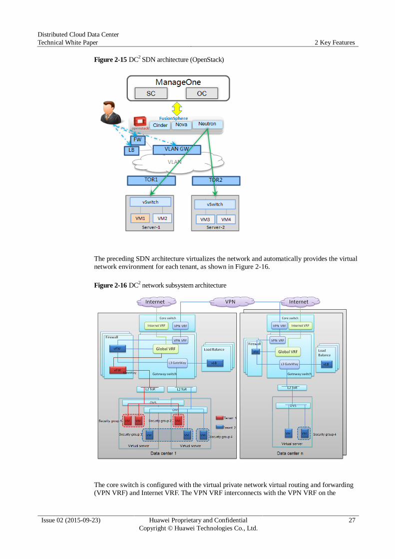
Figure 2-15.
Distributed Cloud Data Center
Technical White Paper 2 Key Features
Issue 02 (2015-09-23) Huawei Proprietary and Confidential
Copyright © Huawei Technologies Co., Ltd.
27
Figure 2-15 DC2 SDN architecture (OpenStack)
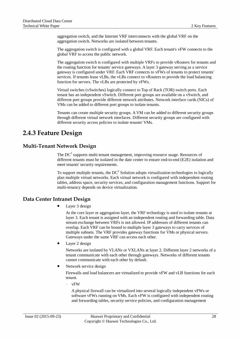
The preceding SDN architecture virtualizes the network and automatically provides the virtual
network environment for each tenant, as shown in Figure 2-16.
Figure 2-16 DC2 network subsystem architecture
The core switch is configured with the virtual private network virtual routing and forwarding (VPN VRF) and Internet VRF. The VPN VRF interconnects with the VPN VRF on the
Distributed Cloud Data Center
Technical White Paper 2 Key Features
Issue 02 (2015-09-23) Huawei Proprietary and Confidential
Copyright © Huawei Technologies Co., Ltd.
28
aggregation switch, and the Internet VRF interconnects with the global VRF on the
aggregation switch. Networks are isolated between tenants.
The aggregation switch is configured with a global VRF. Each tenant's vFW connects to the
global VRF to access the public network.
The aggregation switch is configured with multiple VRFs to provide vRouters for tenants and
the routing function for tenants' service gateways. A layer 3 gateway serving as a service
gateway is configured under VRF. Each VRF connects to vFWs of tenants to protect tenants'
services. If tenants lease vLBs, the vLBs connect to vRouters to provide the load balancing
function for servers. The vLBs are protected by vFWs.
Virtual switches (vSwitches) logically connect to Top of Rack (TOR) switch ports. Each
tenant has an independent vSwitch. Different port groups are available on a vSwitch, and
different port groups provide different network attributes. Network interface cards (NICs) of
VMs can be added to different port groups to isolate tenants.
Tenants can create multiple security groups. A VM can be added to different security groups
through different virtual network interfaces. Different security groups are configured with
different security access policies to isolate tenants' VMs.
2.4.3 Feature Design
Multi-Tenant Network Design
The DC2 supports multi-tenant management, improving resource usage. Resources of
different tenants must be isolated in the date center to ensure end-to-end (E2E) isolation and
meet tenants' security requirements.
To support multiple tenants, the DC2 Solution adopts virtualization technologies to logically
plan multiple virtual networks. Each virtual network is configured with independent routing
tables, address space, security services, and configuration management functions. Support for
multi-tenancy depends on device virtualization.
Data Center Intranet Design Layer 3 design
At the core layer or aggregation layer, the VRF technology is used to isolate tenants at
layer 3. Each tenant is assigned with an independent routing and forwarding table. Data
stream exchange between VRFs is not allowed. IP addresses of different tenants can
overlap. Each VRF can be bound to multiple layer 3 gateways to carry services of
multiple subnets. The VRF provides gateway functions for VMs or physical servers. Gateways under the same VRF can access each other.
Layer 2 design
Networks are isolated by VLANs or VXLANs at layer 2. Different layer 2 networks of a
tenant communicate with each other through gateways. Networks of different tenants cannot communicate with each other by default.
Network service design
Firewalls and load balancers are virtualized to provide vFW and vLB functions for each tenant.
− vFW
A physical firewall can be virtualized into several logically independent vFWs or
software vFWs running on VMs. Each vFW is configured with independent routing
and forwarding tables, security service policies, and configuration management

Distributed Cloud Data Center
Technical White Paper 2 Key Features
Issue 02 (2015-09-23) Huawei Proprietary and Confidential
Copyright © Huawei Technologies Co., Ltd.
29
functions. Modifying vFW configurations by a tenant does not affect the proper
running of other tenants' vFWs. The throughput and number of sessions of vFWs are
limited to ensure that vFWs of a tenant do not occupy vFW resources of other tenants.
− vLB
A physical LB can be virtualized into several logically independent vLBs or software
vLBs running on VMs. Each vLB is configured with independent routing and
forwarding tables, load balancing policies, and configuration management functions.
Modifying vLB configurations by a tenant does not affect the proper running of vLBs
of other tenants' vLBs. The throughput and number of sessions of vLBs are limited to
ensure that vLBs of a tenant do not occupy vLB resources of other tenants.
Inter-Data Center Network Design Internet
Data centers can interconnect with each other through the Internet. Tenants access
services using public IP addresses. Cross-DC resource scheduling is supported, but long
latency may occur in the case of long physical distance due to relatively poor network quality of the Internet.
VPN or private line
Physical data centers, especially remote data centers of enterprises, can interconnect with
each other through leased VPNs or private lines. VPNs and private lines are recommended because of their stability.
2.4.4 Key Features
Table 2-2 Supported modes for VPC network service provisioning
VPC Service Supported Mode
vRouter Manual mode
Network Automatic mode
Subnet Automatic mode
EIP Manual mode
SNAT Manual mode
ACL Manual mode
IPsec VPN Manual mode
LB Manual mode
SEG Automatic mode
VM network Automatic mode
Multi-tenant isolation
Network resources of different tenants are isolated. Each tenant has an independent
network control plane, data forwarding plane, and policy configuration management function. Running of a tenant's resources does not affect other tenants' resources.
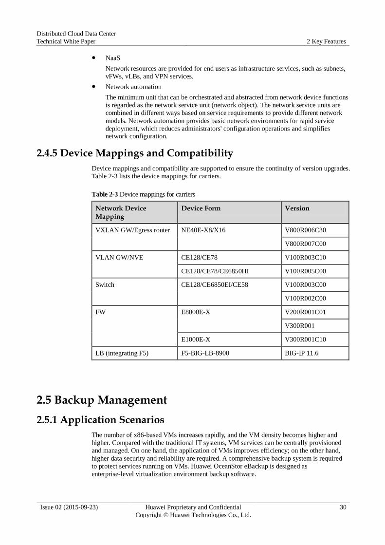
Distributed Cloud Data Center
Technical White Paper 2 Key Features
Issue 02 (2015-09-23) Huawei Proprietary and Confidential
Copyright © Huawei Technologies Co., Ltd.
30
NaaS
Network resources are provided for end users as infrastructure services, such as subnets,
vFWs, vLBs, and VPN services.
Network automation
The minimum unit that can be orchestrated and abstracted from network device functions
is regarded as the network service unit (network object). The network service units are
combined in different ways based on service requirements to provide different network
models. Network automation provides basic network environments for rapid service
deployment, which reduces administrators' configuration operations and simplifies network configuration.
2.4.5 Device Mappings and Compatibility
Device mappings and compatibility are supported to ensure the continuity of version upgrades.
Table 2-3 lists the device mappings for carriers.
Table 2-3 Device mappings for carriers
Network Device Mapping
Device Form Version
VXLAN GW/Egress router NE40E-X8/X16 V800R006C30
V800R007C00
VLAN GW/NVE CE128/CE78 V100R003C10
CE128/CE78/CE6850HI V100R005C00
Switch CE128/CE6850EI/CE58 V100R003C00
V100R002C00
FW E8000E-X V200R001C01
V300R001
E1000E-X V300R001C10
LB (integrating F5) F5-BIG-LB-8900 BIG-IP 11.6
2.5 Backup Management
2.5.1 Application Scenarios
The number of x86-based VMs increases rapidly, and the VM density becomes higher and
higher. Compared with the traditional IT systems, VM services can be centrally provisioned
and managed. On one hand, the application of VMs improves efficiency; on the other hand,
higher data security and reliability are required. A comprehensive backup system is required
to protect services running on VMs. Huawei OceanStor eBackup is designed as
enterprise-level virtualization environment backup software.
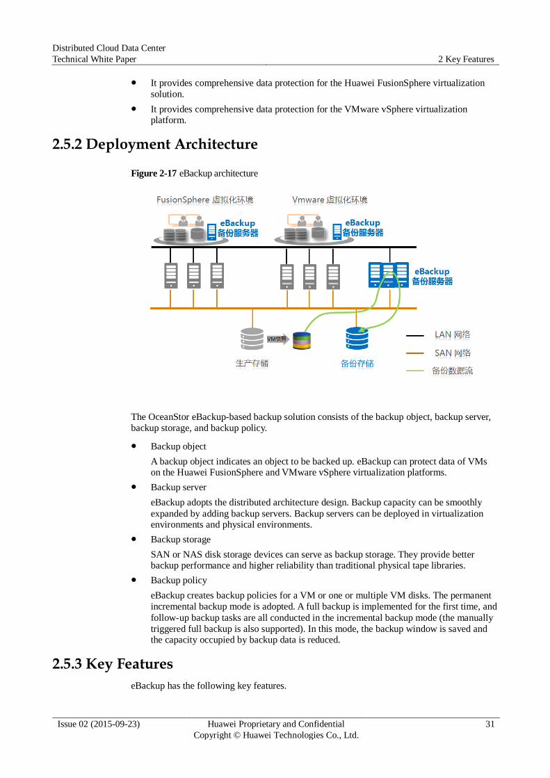
Distributed Cloud Data Center
Technical White Paper 2 Key Features
Issue 02 (2015-09-23) Huawei Proprietary and Confidential
Copyright © Huawei Technologies Co., Ltd.
31
It provides comprehensive data protection for the Huawei FusionSphere virtualization
solution.
It provides comprehensive data protection for the VMware vSphere virtualization platform.
2.5.2 Deployment Architecture
Figure 2-17 eBackup architecture
The OceanStor eBackup-based backup solution consists of the backup object, backup server,
backup storage, and backup policy.
Backup object
A backup object indicates an object to be backed up. eBackup can protect data of VMs on the Huawei FusionSphere and VMware vSphere virtualization platforms.
Backup server
eBackup adopts the distributed architecture design. Backup capacity can be smoothly
expanded by adding backup servers. Backup servers can be deployed in virtualization environments and physical environments.
Backup storage
SAN or NAS disk storage devices can serve as backup storage. They provide better backup performance and higher reliability than traditional physical tape libraries.
Backup policy
eBackup creates backup policies for a VM or one or multiple VM disks. The permanent
incremental backup mode is adopted. A full backup is implemented for the first time, and
follow-up backup tasks are all conducted in the incremental backup mode (the manually
triggered full backup is also supported). In this mode, the backup window is saved and the capacity occupied by backup data is reduced.
2.5.3 Key Features
eBackup has the following key features.
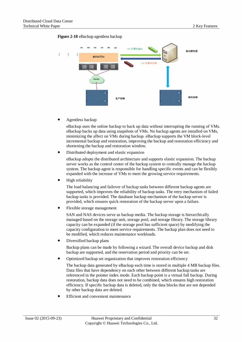
Distributed Cloud Data Center
Technical White Paper 2 Key Features
Issue 02 (2015-09-23) Huawei Proprietary and Confidential
Copyright © Huawei Technologies Co., Ltd.
32
Figure 2-18 eBackup agentless backup
Agentless backup
eBackup uses the online backup to back up data without interrupting the running of VMs.
eBackup backs up data using snapshots of VMs. No backup agents are installed on VMs,
minimizing the affect on VMs during backup. eBackup supports the VM block-level
incremental backup and restoration, improving the backup and restoration efficiency and shortening the backup and restoration window.
Distributed deployment and elastic expansion
eBackup adopts the distributed architecture and supports elastic expansion. The backup
server works as the control center of the backup system to centrally manage the backup
system. The backup agent is responsible for handling specific events and can be flexibly expanded with the increase of VMs to meet the growing service requirements.
High reliability
The load balancing and failover of backup tasks between different backup agents are
supported, which improves the reliability of backup tasks. The retry mechanism of failed
backup tasks is provided. The database backup mechanism of the backup server is provided, which ensures quick restoration of the backup server upon a failure.
Flexible storage management
SAN and NAS devices serve as backup media. The backup storage is hierarchically
managed based on the storage unit, storage pool, and storage library. The storage library
capacity can be expanded (if the storage pool has sufficient space) by modifying the
capacity configuration to meet service requirements. The backup plan does not need to be modified, which reduces maintenance workloads.
Diversified backup plans
Backup plans can be made by following a wizard. The overall device backup and disk
backup are supported, and the reservation period and priority can be set.
Optimized backup set organization that improves restoration efficiency
The backup data generated by eBackup each time is stored in multiple 4 MB backup files.
Data files that have dependency on each other between different backup tasks are
referenced in the pointer index mode. Each backup point is a virtual full backup. During
restoration, backup data does not need to be combined, which ensures high restoration
efficiency. If specific backup data is deleted, only the data blocks that are not depended by other backup data are deleted.
Efficient and convenient maintenance
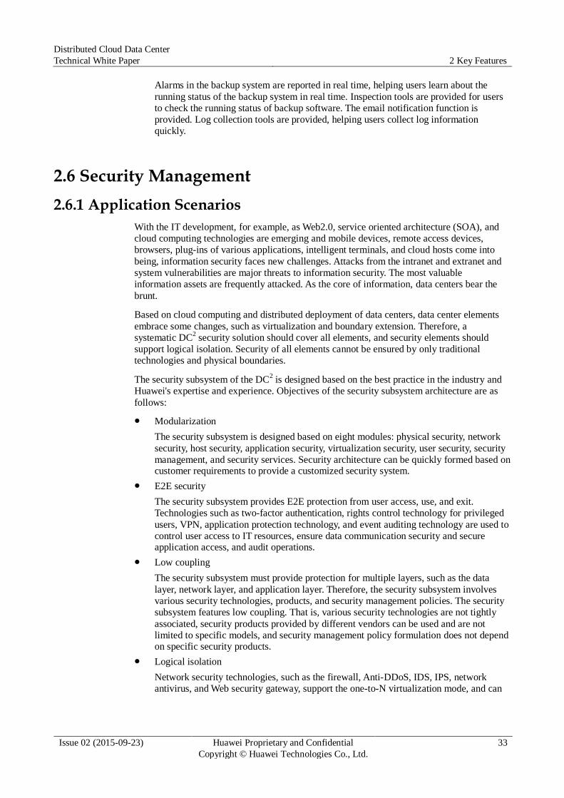
Distributed Cloud Data Center
Technical White Paper 2 Key Features
Issue 02 (2015-09-23) Huawei Proprietary and Confidential
Copyright © Huawei Technologies Co., Ltd.
33
Alarms in the backup system are reported in real time, helping users learn about the
running status of the backup system in real time. Inspection tools are provided for users
to check the running status of backup software. The email notification function is
provided. Log collection tools are provided, helping users collect log information
quickly.
2.6 Security Management
2.6.1 Application Scenarios
With the IT development, for example, as Web2.0, service oriented architecture (SOA), and
cloud computing technologies are emerging and mobile devices, remote access devices,
browsers, plug-ins of various applications, intelligent terminals, and cloud hosts come into
being, information security faces new challenges. Attacks from the intranet and extranet and
system vulnerabilities are major threats to information security. The most valuable
information assets are frequently attacked. As the core of information, data centers bear the
brunt.
Based on cloud computing and distributed deployment of data centers, data center elements
embrace some changes, such as virtualization and boundary extension. Therefore, a
systematic DC2 security solution should cover all elements, and security elements should
support logical isolation. Security of all elements cannot be ensured by only traditional
technologies and physical boundaries.
The security subsystem of the DC2 is designed based on the best practice in the industry and
Huawei's expertise and experience. Objectives of the security subsystem architecture are as
follows:
Modularization
The security subsystem is designed based on eight modules: physical security, network
security, host security, application security, virtualization security, user security, security
management, and security services. Security architecture can be quickly formed based on customer requirements to provide a customized security system.
E2E security
The security subsystem provides E2E protection from user access, use, and exit.
Technologies such as two-factor authentication, rights control technology for privileged
users, VPN, application protection technology, and event auditing technology are used to
control user access to IT resources, ensure data communication security and secure application access, and audit operations.
Low coupling
The security subsystem must provide protection for multiple layers, such as the data
layer, network layer, and application layer. Therefore, the security subsystem involves
various security technologies, products, and security management policies. The security
subsystem features low coupling. That is, various security technologies are not tightly
associated, security products provided by different vendors can be used and are not
limited to specific models, and security management policy formulation does not depend on specific security products.
Logical isolation
Network security technologies, such as the firewall, Anti-DDoS, IDS, IPS, network
antivirus, and Web security gateway, support the one-to-N virtualization mode, and can
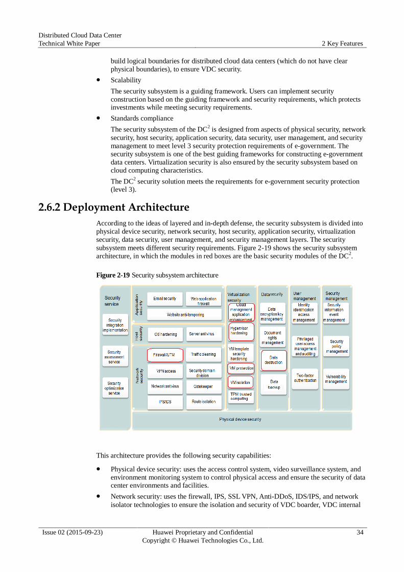
Distributed Cloud Data Center
Technical White Paper 2 Key Features
Issue 02 (2015-09-23) Huawei Proprietary and Confidential
Copyright © Huawei Technologies Co., Ltd.
34
build logical boundaries for distributed cloud data centers (which do not have clear
physical boundaries), to ensure VDC security.
Scalability
The security subsystem is a guiding framework. Users can implement security
construction based on the guiding framework and security requirements, which protects investments while meeting security requirements.
Standards compliance
The security subsystem of the DC2 is designed from aspects of physical security, network
security, host security, application security, data security, user management, and security
management to meet level 3 security protection requirements of e-government. The
security subsystem is one of the best guiding frameworks for constructing e-government
data centers. Virtualization security is also ensured by the security subsystem based on
cloud computing characteristics.
The DC2 security solution meets the requirements for e-government security protection
(level 3).
2.6.2 Deployment Architecture
According to the ideas of layered and in-depth defense, the security subsystem is divided into
physical device security, network security, host security, application security, virtualization
security, data security, user management, and security management layers. The security
subsystem meets different security requirements. Figure 2-19 shows the security subsystem
architecture, in which the modules in red boxes are the basic security modules of the DC2.
Figure 2-19 Security subsystem architecture
This architecture provides the following security capabilities:
Physical device security: uses the access control system, video surveillance system, and
environment monitoring system to control physical access and ensure the security of data center environments and facilities.
Network security: uses the firewall, IPS, SSL VPN, Anti-DDoS, IDS/IPS, and network
isolator technologies to ensure the isolation and security of VDC boarder, VDC internal
Distributed Cloud Data Center
Technical White Paper 2 Key Features
Issue 02 (2015-09-23) Huawei Proprietary and Confidential
Copyright © Huawei Technologies Co., Ltd.
35
system, data, and communication. These technologies prevent data from being damaged,
changed, or disclosed accidentally or intentionally. With these technologies, the system is reliable, secure, and able to run continuously without service interruption.
Host security: protects host OSs. Hosts are protected against attacks by security hardening, antivirus software, host IPS, and host patch management.
Virtualization security: implements virtualization layer hardening, cloud management
application hardening, and VM isolation to ensure virtualization security.
Application security: uses protection technologies, such as the email protection
technology and Web application protection technology, to protect the data on the
application layer. These technologies prevent application data from being damaged, changed, or disclosed accidentally or intentionally.
Data security: uses data encryption, residual data protection, data backup, and other
technologies to ensure data security.
User management: audits access requests from privileged users.
Security management: adopts security information and event management technologies.
Security service: covers security integration, security assessment, security optimization, and phase-specific professional services, and constructs a secure IT system for users.
2.6.3 Key Features
Network Security
The firewall, IDS, IPS, SSL VPN, Anti-DDoS, network antivirus gateway, and data ferry
technologies are used to protect systems and communication data. These technologies prevent
data from being damaged, changed, or disclosed accidentally or intentionally. With these
technologies, the system is reliable, secure, and able to run continuously without service
interruption.
Traditional physical boundaries cannot meet security requirements for scenarios where VDCs
are used as the main body of distributed cloud data centers. To meet the requirements of cloud
technology development, network security products evolve to support virtualization as well as
one-to-N device virtualization, and provide logical network security isolation. The vFW
technology is the most widely used cloud technology. In addition, cloud technology-based
software boundary firewalls and security groups provide comprehensive security protection.
vFW
A firewall is logically divided into multiple vFWs to provide independent security
insurance for enterprises and maximize resource usage of firewalls. A vFW can be provided by a physical firewall or software firewall.
Figure 2-20 Logical architecture of the vFW
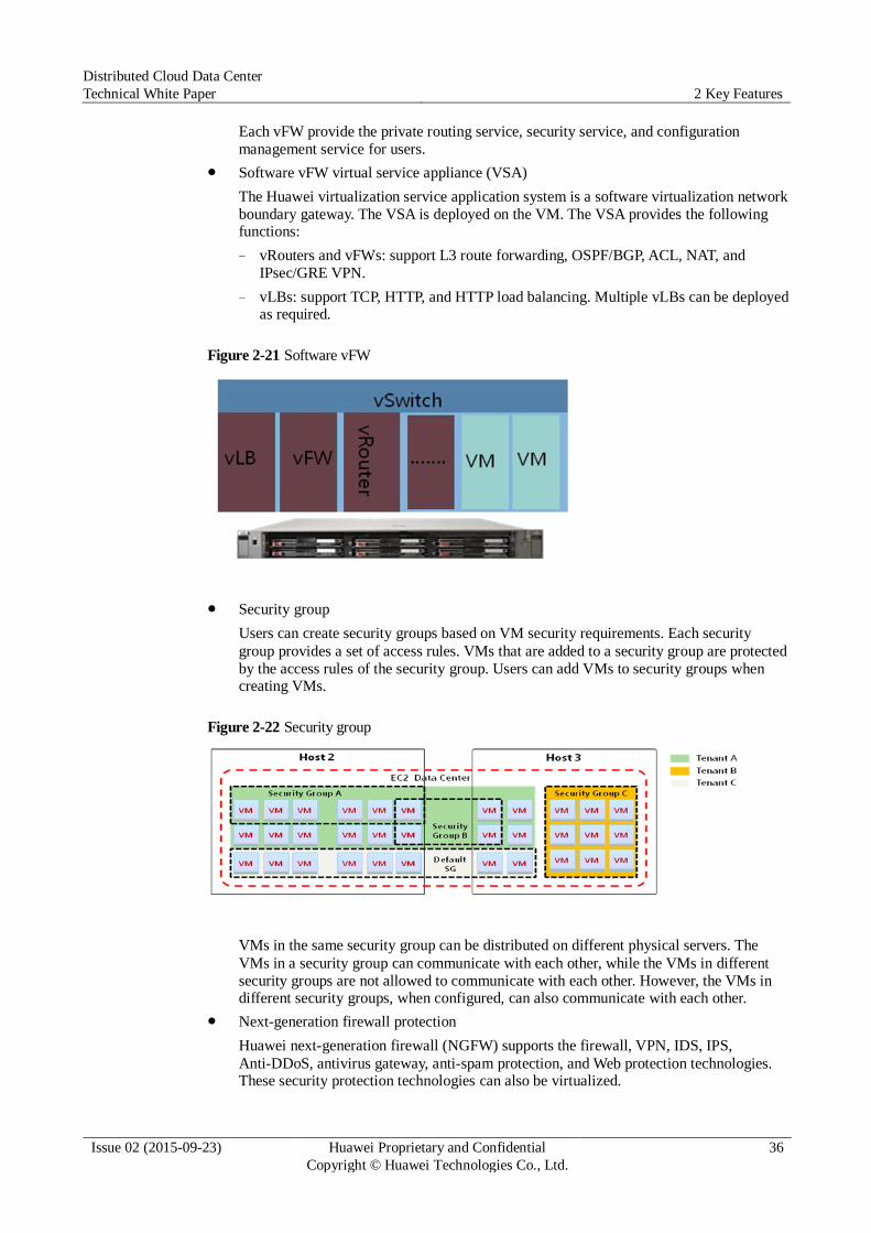
Distributed Cloud Data Center
Technical White Paper 2 Key Features
Issue 02 (2015-09-23) Huawei Proprietary and Confidential
Copyright © Huawei Technologies Co., Ltd.
36
Each vFW provide the private routing service, security service, and configuration
management service for users.
Software vFW virtual service appliance (VSA)
The Huawei virtualization service application system is a software virtualization network
boundary gateway. The VSA is deployed on the VM. The VSA provides the following functions:
− vRouters and vFWs: support L3 route forwarding, OSPF/BGP, ACL, NAT, and
IPsec/GRE VPN.
− vLBs: support TCP, HTTP, and HTTP load balancing. Multiple vLBs can be deployed as required.
Figure 2-21 Software vFW
Security group
Users can create security groups based on VM security requirements. Each security
group provides a set of access rules. VMs that are added to a security group are protected
by the access rules of the security group. Users can add VMs to security groups when creating VMs.
Figure 2-22 Security group
VMs in the same security group can be distributed on different physical servers. The
VMs in a security group can communicate with each other, while the VMs in different
security groups are not allowed to communicate with each other. However, the VMs in different security groups, when configured, can also communicate with each other.
Next-generation firewall protection
Huawei next-generation firewall (NGFW) supports the firewall, VPN, IDS, IPS,
Anti-DDoS, antivirus gateway, anti-spam protection, and Web protection technologies. These security protection technologies can also be virtualized.
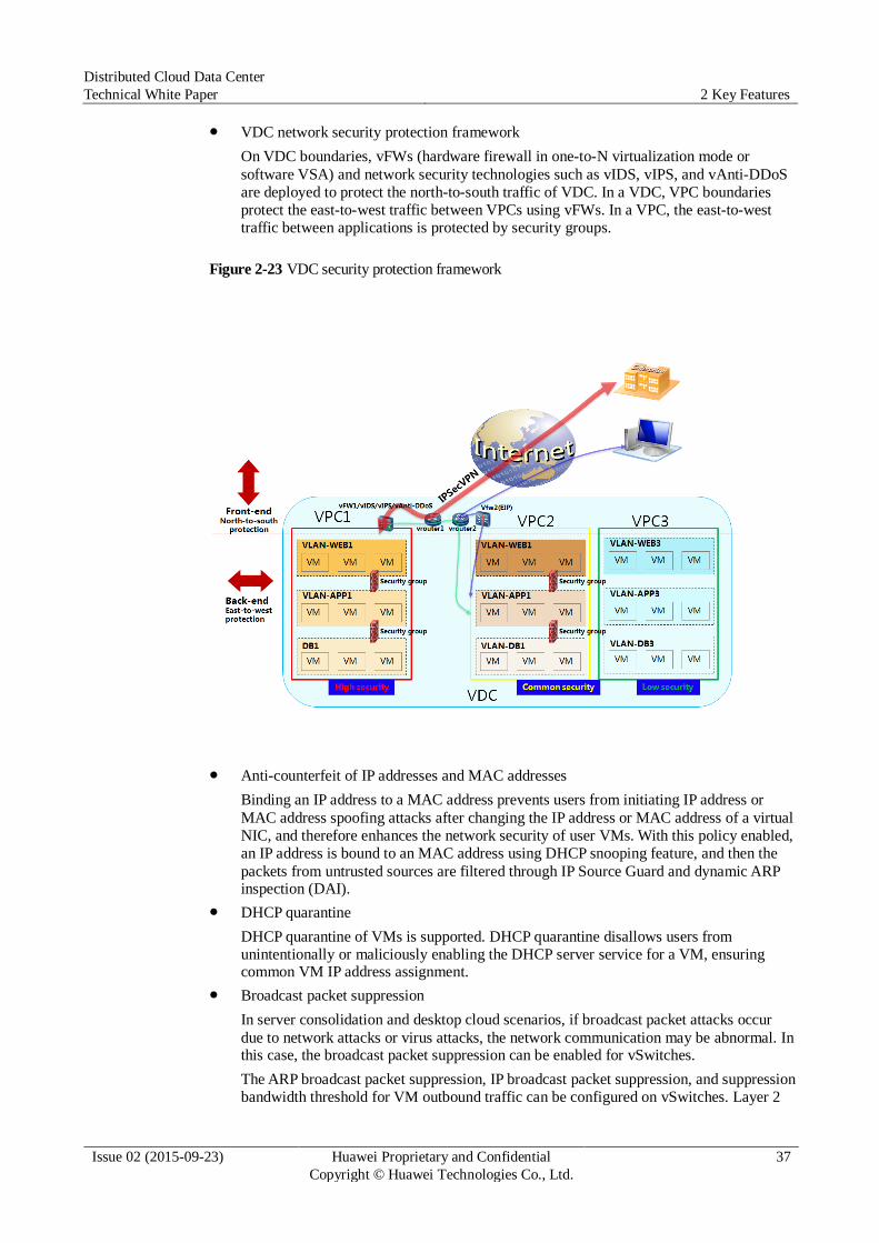
Distributed Cloud Data Center
Technical White Paper 2 Key Features
Issue 02 (2015-09-23) Huawei Proprietary and Confidential
Copyright © Huawei Technologies Co., Ltd.
37
VDC network security protection framework
On VDC boundaries, vFWs (hardware firewall in one-to-N virtualization mode or
software VSA) and network security technologies such as vIDS, vIPS, and vAnti-DDoS
are deployed to protect the north-to-south traffic of VDC. In a VDC, VPC boundaries
protect the east-to-west traffic between VPCs using vFWs. In a VPC, the east-to-west
traffic between applications is protected by security groups.
Figure 2-23 VDC security protection framework
Anti-counterfeit of IP addresses and MAC addresses
Binding an IP address to a MAC address prevents users from initiating IP address or
MAC address spoofing attacks after changing the IP address or MAC address of a virtual
NIC, and therefore enhances the network security of user VMs. With this policy enabled,
an IP address is bound to an MAC address using DHCP snooping feature, and then the
packets from untrusted sources are filtered through IP Source Guard and dynamic ARP inspection (DAI).
DHCP quarantine
DHCP quarantine of VMs is supported. DHCP quarantine disallows users from
unintentionally or maliciously enabling the DHCP server service for a VM, ensuring common VM IP address assignment.
Broadcast packet suppression
In server consolidation and desktop cloud scenarios, if broadcast packet attacks occur
due to network attacks or virus attacks, the network communication may be abnormal. In this case, the broadcast packet suppression can be enabled for vSwitches.
The ARP broadcast packet suppression, IP broadcast packet suppression, and suppression bandwidth threshold for VM outbound traffic can be configured on vSwitches. Layer 2
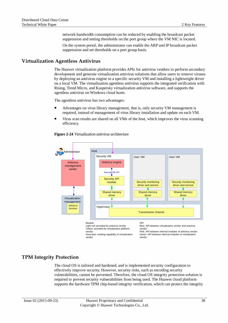
Distributed Cloud Data Center
Technical White Paper 2 Key Features
Issue 02 (2015-09-23) Huawei Proprietary and Confidential
Copyright © Huawei Technologies Co., Ltd.
38
network bandwidth consumption can be reduced by enabling the broadcast packet
suppression and setting thresholds on the port group where the VM NIC is located.
On the system portal, the administrator can enable the ARP and IP broadcast packet suppression and set thresholds on a port group basis.
Virtualization Agentless Antivirus
The Huawei virtualization platform provides APIs for antivirus vendors to perform secondary
development and generate virtualization antivirus solutions that allow users to remove viruses
by deploying an antivirus engine in a specific security VM and installing a lightweight driver
on a local VM. The virtualization agentless antivirus supports the integrated verification with
Rising, Trend Micro, and Kaspersky virtualization antivirus software, and supports the
agentless antivirus on Windows cloud hosts.
The agentless antivirus has two advantages:
Advantages on virus library management, that is, only security VM management is
required, instead of management of virus library installation and update on each VM.
Virus scan results are shared on all VMs of the host, which improves the virus scanning efficiency.
Figure 2-24 Virtualization antivirus architecture
Host
Security VM
Security VM API
Hypervisor
User VM
Antivirus
management
center
Antivirus engine
Security API
module
Module:
Light red: provided by antivirus vendor
Yellow: provided by virtualization platform
vendor
Gray blue: existing capability of virtualization
vendor
Administrator
Transmission channel
API:
Blue: API between virtualization vendor and antivirus
vendor
Pink: API between internal modules of antivirus vendor
Green: API between internal modules of virtualization
vendor
Security monitoring
driver and service
Shared memory
driver
Shared memory
driverVirtualization
management
Antivirus
function
User VM
Security monitoring
driver and service
Shared memory
driver
TPM Integrity Protection
The cloud OS is tailored and hardened, and is implemented security configuration to
effectively improve security. However, security risks, such as encoding security
vulnerabilities, cannot be prevented. Therefore, the cloud OS integrity protection solution is
required to prevent security vulnerabilities from being used. The Huawei cloud platform
supports the hardware TPM chip-based integrity verification, which can protect the integrity
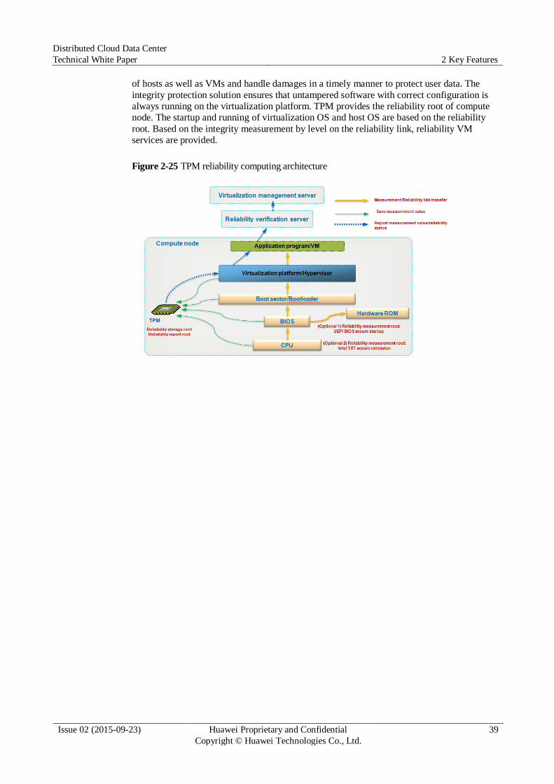
Distributed Cloud Data Center
Technical White Paper 2 Key Features
Issue 02 (2015-09-23) Huawei Proprietary and Confidential
Copyright © Huawei Technologies Co., Ltd.
39
of hosts as well as VMs and handle damages in a timely manner to protect user data. The
integrity protection solution ensures that untampered software with correct configuration is
always running on the virtualization platform. TPM provides the reliability root of compute
node. The startup and running of virtualization OS and host OS are based on the reliability
root. Based on the integrity measurement by level on the reliability link, reliability VM
services are provided.
Figure 2-25 TPM reliability computing architecture
Distributed Cloud Data Center
Technical White Paper 3 Typical Deployment
Issue 02 (2015-09-23) Huawei Proprietary and Confidential
Copyright © Huawei Technologies Co., Ltd.
40
3 Typical Deployment
About This Chapter
The following table lists the main information in this chapter.
Title Content
3.1 Single Data Center
Deployment
Describes the physical deployment and recommended
configurations of a single cloud data center.
3.2 Distributed Data Center
Deployment
Describes the deployment architecture of multiple cloud
data centers.
3.1 Single Data Center Deployment
3.1.1 Physical Architecture
Figure 3-1 shows the physical deployment for the flattened two-layer architecture.
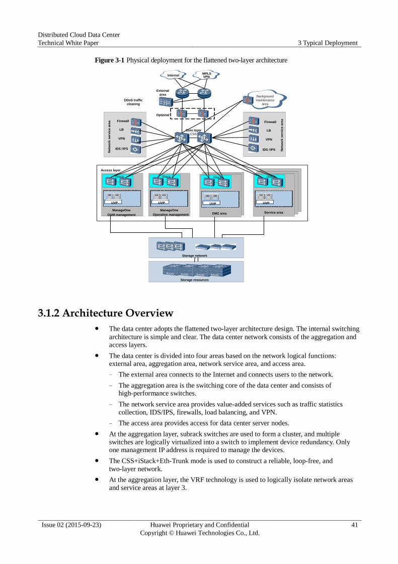
Distributed Cloud Data Center
Technical White Paper 3 Typical Deployment
Issue 02 (2015-09-23) Huawei Proprietary and Confidential
Copyright © Huawei Technologies Co., Ltd.
41
Figure 3-1 Physical deployment for the flattened two-layer architecture
3.1.2 Architecture Overview
The data center adopts the flattened two-layer architecture design. The internal switching
architecture is simple and clear. The data center network consists of the aggregation and access layers.
The data center is divided into four areas based on the network logical functions: external area, aggregation area, network service area, and access area.
− The external area connects to the Internet and connects users to the network.
− The aggregation area is the switching core of the data center and consists of high-performance switches.
− The network service area provides value-added services such as traffic statistics
collection, IDS/IPS, firewalls, load balancing, and VPN.
− The access area provides access for data center server nodes.
At the aggregation layer, subrack switches are used to form a cluster, and multiple
switches are logically virtualized into a switch to implement device redundancy. Only one management IP address is required to manage the devices.
The CSS+iStack+Eth-Trunk mode is used to construct a reliable, loop-free, and
two-layer network.
At the aggregation layer, the VRF technology is used to logically isolate network areas
and service areas at layer 3.
CSS
External
area
iStack
Core layer
DDoS traffic
cleaning
UVP
InternetMPLS VPN
Storage network
Storage resources
iStack
UVP
ManageOne
Operation management
iStack
UVP
DMZ areaManageOne
O&M management
iStack
UVP
Service area
Firewall
LB
VPN
IDS / IPS
Firewall
LB
VPN
IDS / IPS
Background
maintenance
area
Optional
Access layer
Ne
two
rk s
erv
ice
are
a
Ne
two
rk s
erv
ice
are
a
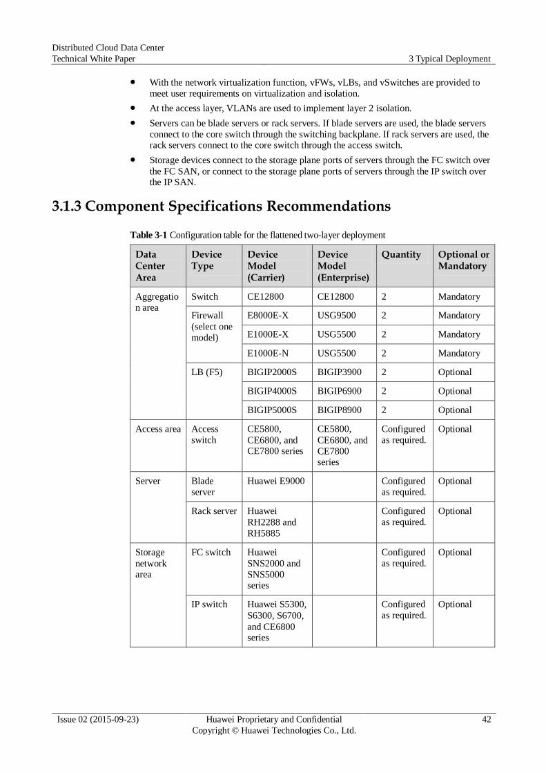
Distributed Cloud Data Center
Technical White Paper 3 Typical Deployment
Issue 02 (2015-09-23) Huawei Proprietary and Confidential
Copyright © Huawei Technologies Co., Ltd.
42
With the network virtualization function, vFWs, vLBs, and vSwitches are provided to
meet user requirements on virtualization and isolation.
At the access layer, VLANs are used to implement layer 2 isolation.
Servers can be blade servers or rack servers. If blade servers are used, the blade servers
connect to the core switch through the switching backplane. If rack servers are used, the rack servers connect to the core switch through the access switch.
Storage devices connect to the storage plane ports of servers through the FC switch over
the FC SAN, or connect to the storage plane ports of servers through the IP switch over the IP SAN.
3.1.3 Component Specifications Recommendations
Table 3-1 Configuration table for the flattened two-layer deployment
Data Center Area
Device Type
Device Model (Carrier)
Device Model (Enterprise)
Quantity Optional or Mandatory
Aggregatio
n area
Switch CE12800 CE12800 2 Mandatory
Firewall
(select one
model)
E8000E-X USG9500 2 Mandatory
E1000E-X USG5500 2 Mandatory
E1000E-N USG5500 2 Mandatory
LB (F5) BIGIP2000S BIGIP3900 2 Optional
BIGIP4000S BIGIP6900 2 Optional
BIGIP5000S BIGIP8900 2 Optional
Access area Access
switch
CE5800,
CE6800, and CE7800 series
CE5800,
CE6800, and
CE7800 series
Configured
as required.
Optional
Server Blade
server
Huawei E9000 Configured
as required.
Optional
Rack server Huawei
RH2288 and
RH5885
Configured
as required.
Optional
Storage
network area
FC switch Huawei
SNS2000 and
SNS5000 series
Configured
as required.
Optional
IP switch Huawei S5300,
S6300, S6700,
and CE6800 series
Configured
as required.
Optional
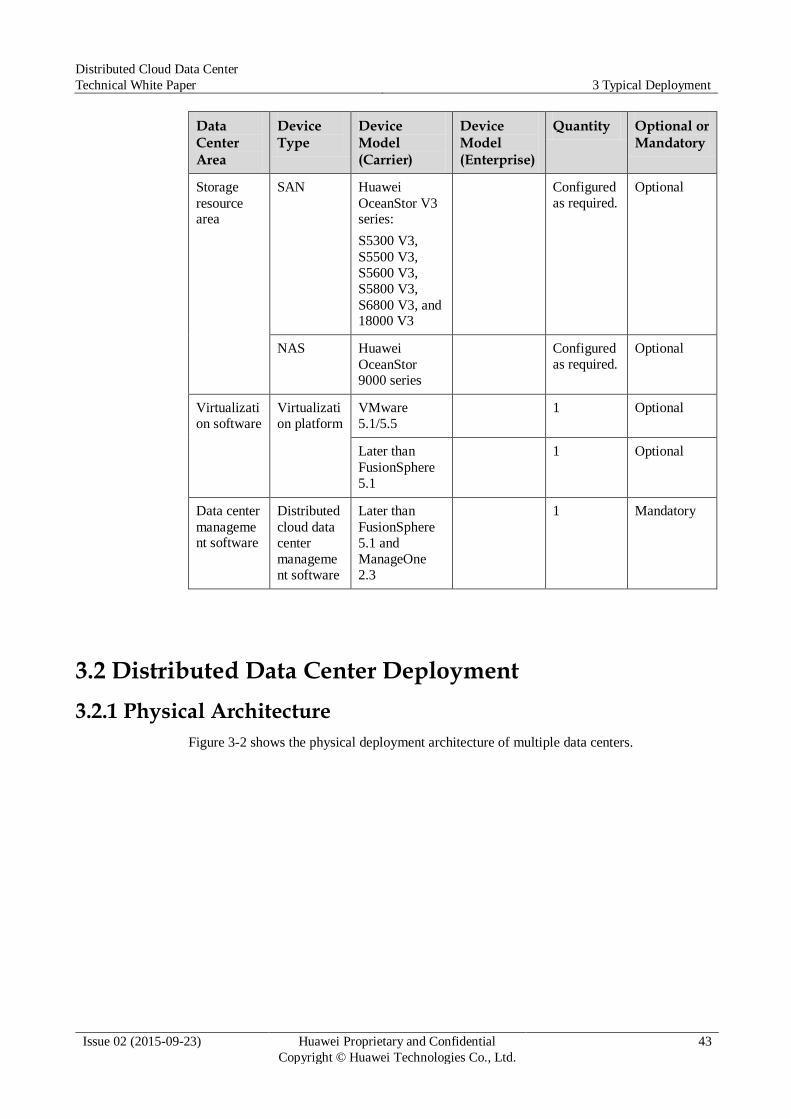
Distributed Cloud Data Center
Technical White Paper 3 Typical Deployment
Issue 02 (2015-09-23) Huawei Proprietary and Confidential
Copyright © Huawei Technologies Co., Ltd.
43
Data Center Area
Device Type
Device Model (Carrier)
Device Model (Enterprise)
Quantity Optional or Mandatory
Storage
resource area
SAN Huawei
OceanStor V3 series:
S5300 V3,
S5500 V3,
S5600 V3,
S5800 V3,
S6800 V3, and 18000 V3
Configured
as required.
Optional
NAS Huawei
OceanStor 9000 series
Configured
as required.
Optional
Virtualizati
on software
Virtualizati
on platform
VMware
5.1/5.5
1 Optional
Later than
FusionSphere
5.1
1 Optional
Data center
management software
Distributed
cloud data
center
manageme
nt software
Later than
FusionSphere
5.1 and
ManageOne
2.3
1 Mandatory
3.2 Distributed Data Center Deployment
3.2.1 Physical Architecture
Figure 3-2 shows the physical deployment architecture of multiple data centers.
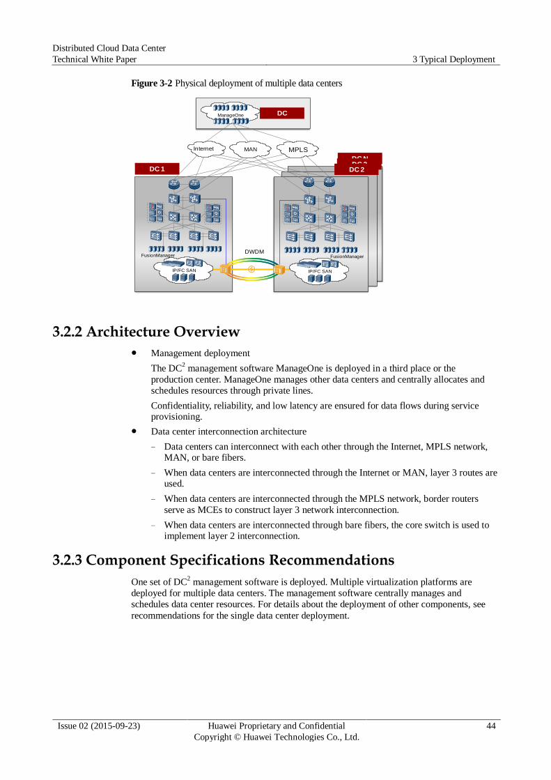
Distributed Cloud Data Center
Technical White Paper 3 Typical Deployment
Issue 02 (2015-09-23) Huawei Proprietary and Confidential
Copyright © Huawei Technologies Co., Ltd.
44
Figure 3-2 Physical deployment of multiple data centers
3.2.2 Architecture Overview
Management deployment
The DC2 management software ManageOne is deployed in a third place or the
production center. ManageOne manages other data centers and centrally allocates and
schedules resources through private lines.
Confidentiality, reliability, and low latency are ensured for data flows during service provisioning.
Data center interconnection architecture
− Data centers can interconnect with each other through the Internet, MPLS network, MAN, or bare fibers.
− When data centers are interconnected through the Internet or MAN, layer 3 routes are used.
− When data centers are interconnected through the MPLS network, border routers
serve as MCEs to construct layer 3 network interconnection.
− When data centers are interconnected through bare fibers, the core switch is used to implement layer 2 interconnection.
3.2.3 Component Specifications Recommendations
One set of DC2 management software is deployed. Multiple virtualization platforms are
deployed for multiple data centers. The management software centrally manages and
schedules data center resources. For details about the deployment of other components, see
recommendations for the single data center deployment.
DC NDC 3
DC 1
IP/FC SAN IP/FC SAN
DC 2
Internet
DWDM
ManageOne DC
MAN MPLS
FusionManager FusionManager