Document
24
The Global Magazine of Leica Geosystems Construction site in a mountain Monitoring: Reducing risk >> page 03 >> page 07 55
-
Upload
antonis-an -
Category
Documents
-
view
213 -
download
1
description
http://www.leica-geosystems.com/media/new/product_solution/Reporter_55_MAG_low_741803_en.pdf
Transcript of Document

The Global Magazine of Leica Geosystems
Construction site in a mountain
Monitoring: Reducing risk
>> page 03
>> page 07
55
� | Reporter
CON
TEN
TS
in this issue:
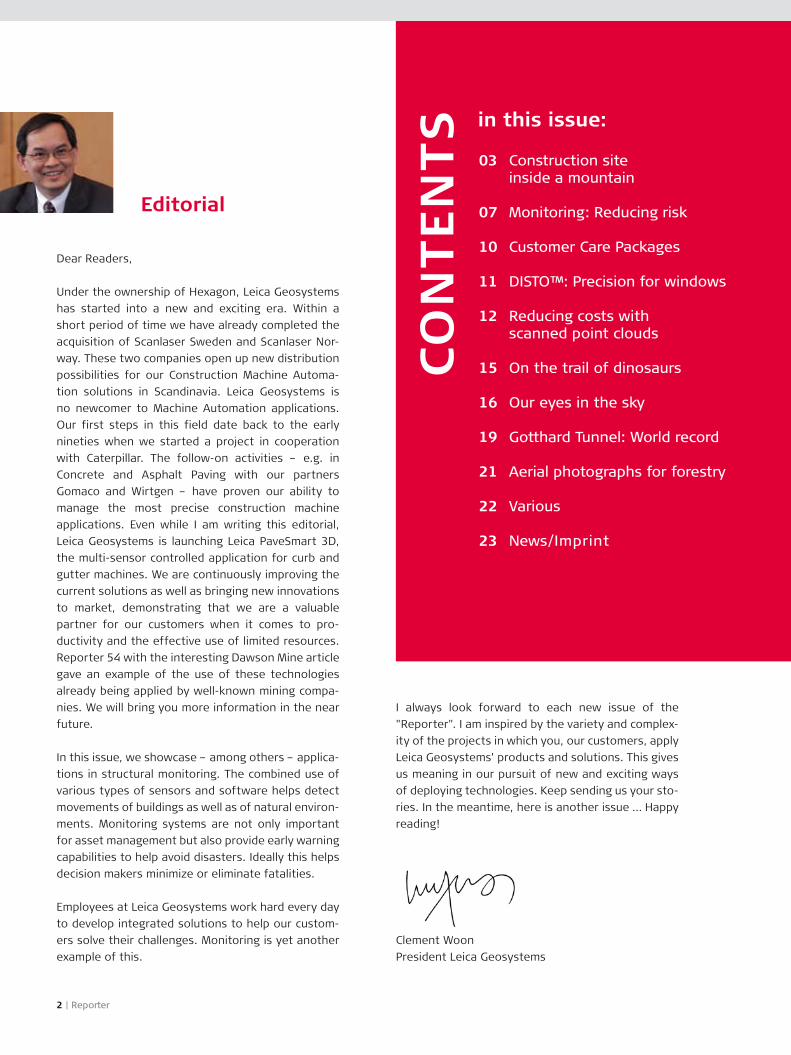
Dear Readers,
Under the ownership of Hexagon, Leica Geosystems has started into a new and exciting era. Within a short period of time we have already completed the acquisition of Scanlaser Sweden and Scanlaser Nor-way. These two companies open up new distribution possibilities for our Construction Machine Automa-tion solutions in Scandinavia. Leica Geosystems is no newcomer to Machine Automation applications. Our first steps in this field date back to the early nineties when we started a project in cooperation with Caterpillar. The follow-on activities – e.g. in Concrete and Asphalt Paving with our partners Gomaco and Wirtgen – have proven our ability to manage the most precise construction machine applications. Even while I am writing this editorial, Leica Geosystems is launching Leica PaveSmart 3D, the multi-sensor controlled application for curb and gutter machines. We are continuously improving the current solutions as well as bringing new innovations to market, demonstrating that we are a valuable partner for our customers when it comes to pro-ductivity and the effective use of limited resources. Reporter 54 with the interesting Dawson Mine article gave an example of the use of these technologies already being applied by well-known mining compa-nies. We will bring you more information in the near future.
In this issue, we showcase – among others – applica-tions in structural monitoring. The combined use of various types of sensors and software helps detect movements of buildings as well as of natural environ-ments. Monitoring systems are not only important for asset management but also provide early warning capabilities to help avoid disasters. Ideally this helps decision makers minimize or eliminate fatalities.
Employees at Leica Geosystems work hard every day to develop integrated solutions to help our custom-ers solve their challenges. Monitoring is yet another example of this.
I always look forward to each new issue of the "Reporter". I am inspired by the variety and complex-ity of the projects in which you, our customers, apply Leica Geosystems’ products and solutions. This gives us meaning in our pursuit of new and exciting ways of deploying technologies. Keep sending us your sto-ries. In the meantime, here is another issue … Happy reading!
Clement WoonPresident Leica Geosystems
Construction site inside a mountain
Monitoring: Reducing risk
Customer Care Packages
DISTO™: Precision for windows
Reducing costs with scanned point clouds
On the trail of dinosaurs
Our eyes in the sky
Gotthard Tunnel: World record
Aerial photographs for forestry
Various
News/Imprint
03
07
10
11
1�
15
16
19
�1
��
�3
Editorial

The Global Magazine of Leica Geosystems | 3
by Agnes Zeiner, Pictures: Vorarlberger Illwerke AG
So this is it – the most spectacular construc-tion site in the entire region? In front of us, at around 1000 metres above sea level, is a poorly-lit tunnel leading into the heart of the mountain, with two more similar holes at some distance. St. Barbara, the local patron saint of miners, smiles from behind the protective grating. Not that anyone who is unused to this type of loca-tion will find a lot to smile about. Never mind, here we are already, straight into the busy world of Kopswerk II, where Vorarlberger Illwerke AG have blasted the biggest power station construc-tion site in Europe into the side of a mountain.
Delivering large quantities of electricity as quickly as possible – this will be the job of Kopswerk II when it goes into partial operation in the 4th quarter of 2007 and full operation in the spring of 2008. With a cur-rent portfolio of nine power stations, four reservoirs and several surface basins, the Vorarlberger Illwerke AG supply peak-load electricity and regulating ener-gy to their partners Energie Baden Württemberg AG (EnBW) and the states of Tyrol and Vorarlberg, Aus-
tria. Deregulation of electricity and continued efforts to widen the use of alternative sources of energy such as wind power mean that increased importance is being placed on the supply of peak-load electricity and regulating energy. "Kopswerk II is not designed to continuously generate more current but rather to deliver high-quality peak-load electricity in the short-est possible time. When one of our partners signals demand, it will take less than a minute before we deliver the required peak-load electricity", explains Rupert Zischinsky, Head of Measuring Technology at Vorarlberger Illwerke and our guide through the Kop-swerk II plant. The power station will be run from the Illwerke Control Centre in Rodund in Montafon, a few kilometres away.
Energy saving energy generationPelton turbines are used to go from standstill to 100 percent output within the space of a minute. When generating regulating energy, the principle of a "hydraulic short circuit“ is applied: water is released from the Kops dam, 1800m above sea level, through the turbine, driving the turbine and generating elec-tricity. A generator in turn drives a pump which pumps the water back to the turbine, completing the
Construction site inside a mountain
>>

� | Reporter
circuit. When energy is required in the grid, water flows from the Kops reservoir, but when energy is to be taken from the grid, water is pumped back up to the Kops reservoir. The power station is optimised to keep frictional losses as low as possible: when the turbines are idling, only enough water is released from the reservoir to compensate for the small loss of water due to friction. The system virtually main-tains itself and saves a lot of energy, as the water only needs to be pumped to the turbine, but not all the way back up to the dam 800 metres further up the mountain. When the turbine is active, water flows with a pressure of 3 bar into the compensation basin Rifa located slightly higher up.
The cavern – the heart of the power stationHowever, it is also precisely this technology that allows Rupert Zischinsky and his 10-person survey team to show off all their skills. The turbines, gen-erators, and pumps are hidden 100 metres deep inside the mountain in a cavern of truly awe-inspir-ing size. The height alone is enormous: at over 60 metres high and 30 metres in diameter, the machine room could comfortably house any parish church in Austria with space to spare above the tip of the spire. Well, nearly every church. "We couldn’t really fit the Stephansdom in Vienna in“, adds Zischinsky with a smile.
surrounding concrete frame on delivery. Once the plant is fully operational, the cavern will be home to three such towers.
This in itself is going to be quite a logistical feat – each pump alone weighs around 600 tons, and the heaviest parts of the generators each weigh 123 tons and will be transported as single units through the narrow Montafon valley to the Kopswerk II – and it is going to be quite a challenge for the surveyors. Zischinsky explains: "The cavern will undergo some deformation until the work in the cavern is finished and the machines have been taken into operation for the first time. Although this is kept within limits thanks to the egg-shaped design and other fac-tors, we are still expecting deformations of up to 20 mm. We needed to calculate this in advance in order to guarantee the giant machine towers would work correctly – anything else would result in a catastrophe due to the masses that would start to move.“ Accuracies in the region of a few tenths of a millimetre will be required during the fitting of the machines. "Accuracy and reliability are vital here – not just for the team, but also for the equipment. This is one of the reasons why we decided to opt for levels, optical plummets and total stations from Leica Geosystems.“
Continuous geotechnical measurementsTwo reference points have been sunk into the floor plate of the cavern as the basis for all calculations performed by the surveyors. Daily geotechnical con-trol measurements are performed with reference to these two points. This is done to continuously log rock movement – whether due to natural causes or because of the building activities – so that appropri-ate measures can be taken immediately if any devia-tions become too great. In the cavern alone, more than 350 points have been installed which are mea-sured every day. The team is supported in its efforts by a monitoring program developed specially with Leica GeoC++ for the total station Leica TPS1200.
In addition to the continuous measurements in the cavern, checks also need to be performed in the tunnel and in the sloped shaft, which leads from the Kops reservoir to the cavern of the Kopswerk II plant, and the shafts need to be plumbed. "Our main chal-lenges in the tunnel are particularly the tight curves and the narrow diameter, which is often only a few metres", explains Zischinsky. After every 2 km of
>>
The complete machine tower comprising the tur-bine, generator and pump will be nearly 40 metres high once completed, as the first three machine parts will be placed directly above each other and will also need to be integrated vertically into the
Dimensions of the Stephansdom (St. Stephen’s cathedral):
Overall length: 107.2 m
Overall width: 34.2 m
Height of the southern tower: 136.4 m
Height of the northern tower: 68.3 m
Dimensions of the cavern:Overall length: 88 m
Maximum width: 30.5 m
Maximum height: 60.5 m
Overall height of the hydroelectric
generating set: 38 m

The measurements in the Montafon mountains demanded excellent balance and no small amount of skill – not just
on the side of the instruments.
The Global Magazine of Leica Geosystems | 5
tunnel excavation, main checks are performed which must be accurate to less than 2 ppm (i.e. 2 mm over 1 km).
Basic network with a 100-metre height differenceThe team of surveyors from Illwerke already put one of the most difficult challenges behind them: the creation of the base-network in the narrow Mon-tafon valley: "It took us the whole summer of 2003 to complete the levelling and a detail survey for the entire location. It was incredibly hard work which challenged more than just our 10-person team – we also got students to help, and even the fire brigade lent us an occasional hand", explains Rupert Zischin-sky. Some might say that the beautiful "summer of the century“ in 2003 was a present from the heavens to the Illwerke surveyors. The defining factors when drawing up the base-net-work were the geographic peculiarities of the Mon-tafon. Located directly at the foot of the Silvretta mountains with snow-covered peaks reaching above the 3000 m mark, the surveyors had to work with height differences of more than 1000 m within the base-network alone – a fact that challenged the fit-ness levels of those involved as much as the tech- >>
nology. The surrounding mountains and dense for-estation of the slopes meant that GPS could only rarely be used. The surveyors relied primarily on Leica TCA2003 total stations and Leica DNA03 lev-els. In total, around 3,871 levelling set-ups were performed, the equivalent of a horizontal precision level-run of 154 km.
Involving people and the environmentDespite the fact that up to 320 workers are involved day and night in the three different sections of the Kopswerk II project (high-pressure gallery, surge chamber and cavern), from the outside the construc-tion site is not exactly impressive. Only the number of office-, changing- and workshop- trailers, hidden from the glances of casual tourists drifting through the Montafon behind a tall fence on the opposite side of the road, gives any indication of the size of the project. The Vorarlberger Illlwerke have invested an impressive € 360 million here in order to increase their output from 1248 to 1700 MW of turbine power once the plant is fully operational, allowing them to supply around 2272 million kWh of electricity to their partners.
An unprecedented, on-going information cam-paign and the involvement of the population in the

The cavern with its three machine towers
will form the heart of the power station.
6 | Reporter
progress of the project via a designated website (www.kopswerk2.at), the project newsletter, tours through the cavern, and open communication, all combine to make Kopswerk II not just a showcase project for Vorarlberger Illwerke, but also allow the roughly 150 residents and the people of the region to share in it.
The fact that they are open to the project and have even shown interest in it is probably due to the fact that, even at this stage, the impact of the project has been minimised, since the bulk of the work is being performed underground. "Once it is up and
>>
Kopswerk II www.kopswerk�.at
Section 1: High-pressure gallery, length around 5.5 km.
Section �: High-pressure shaft (length 1135 m, overcomes a
height difference of 710 m) and surge chamber
Section 3: Cavern powerhouse and bottom water systems
Work is taking place simultaneously on all three sections.
Investment: € 360 million
Completion: 2008
Leica Geosystems equipment used:
Leica DNA03 digital level
Optical high-precision plummets NL and ZL
Leica TCRA1201 total stations
Leica TCA2003 and Leica TDA5005
high-precision total stations
Leica GPS500 receiver
Software Leica GeoC++
Vorarlberger Illwerke AG www.illwerke.at
The company Vorarlberger Illwerke AG was founded in
1924 and has been a public limited company since 1927.
The head office is in Bregenz/Austria. The principal
shareholder is the state of Vorarlberg, Austria, with a
share of over 95 percent.
Turnover: € 131 million
Employees: 561
running you won’t really notice that the power sta-tion is there, apart from the access road and a large entrance gate on the side of the mountain opposite the Rifa basin. The head water system, powerhouse and bottom water system are located inside the mountain, and because the plant uses an existing head lake there has been no need to build a reser-voir or even modify natural lakes“, Rupert Zischinsky explains with a clear sense of pride. A large-scale construction site that sets an example both socially and ecologically? If such a thing exists, it is the Kops-werk II project.

The Sunshine Skyway Bridge in Florida is the longest cable-stayed concrete bridge in the world.
The Global Magazine of Leica Geosystems | 7
Bridges with increasing spans, skyscrapers, tun-nels and railway lines all represent tough chal-lenges for engineers. In the worst case, changes in the ground or the environment can have cat-astrophic effects on such monumental struc-tures. What can be done to prevent this type of catastrophe from happening?
Potential problems need to be anticipated and dealt with during the planning phase of extreme struc-tures such as dams, tunnels or skyscrapers. This is where the structural monitoring systems from Leica Geosystems can help, as they allow continuous monitoring of critical points, resulting in a massive increase in safety. Large bridges are not only exposed
Monitoring: Reducing risk
>>
to daunting traffic loads, but also to a wide variety of extreme weather and environmental influences. Leica Geosystems monitoring systems are capable of detecting the tiniest changes – something that has been underlined by recent examples at the Jian-gyin Yangtze River Bridge in China and the Sunshine Skyway Bridge in Florida. Engineers also faced simi-lar challenges during the expansion of Dulles Airport in Washington and the construction of the Kowloon Airport Express railway line in Hong Kong.
China’s longest suspension bridgeAt 3,071 meters, the Jiangyin Yangtze River High-way Bridge is the longest suspension bridge in China and the fourth-longest in the world. It goes with-

� | Reporter
out saying that the requirements in terms of safety are correspondingly high. The satellite-based bridge monitoring system from Leica Geosystems uses the Global Positioning System (GPS) to offer valuable services. During the construction phase, environ-mental factors were seen as the primary sources of errors in and around the bridge. The bridge monitor-ing system is capable of detecting high-frequency vibrations – allowing the geometry of the bridge to be monitored in real time under any weather condi-tions. Monitoring with the aid of GPS improves the cost-effectiveness and efficiency of maintenance work, provides quantitative information which can be analyzed by senior management, offers a basis for decision-making processes relating to any traffic control measures, ensures the structural safety of the bridge, and allows a reliable assessment of the safety of the bridge.
A powerful complimentThe Sunshine Skyway Bridge in Florida was anoth-er tough challenge for the engineers. A structural monitoring system from Leica Geosystems has also been installed on this bridge – with quite some suc-cess, according to the renowned “Bridges” magazine: “The Sunshine Skyway Bridge project demonstrates that the positions of autonomous sites located on a bridge can be measured automatically using GPS,
in near real time, with centimeter-level accuracies. The results shown here are measurements every 15 minutes relative to a reference site 16 km away, and yield 0.5 centimeter horizontal and 1.7 cm vertical accuracies. These 15-minute measurements provide sufficient accuracy to reveal a complex variety of motion at each point monitored on the bridge. These GPS results were used to refine a simple numeri-cal model capable of predicting the motion of the bridge under a variety of environmental conditions. This type of monitoring is recognized as a power-ful compliment to conventional, periodic inspections and maintenance, as it can reveal subtle or unseen changes in structure from daily wear and tear, aging or extraordinary events such as hurricanes, floods or earthquakes."
Express railway line with high safety standardsThe city of Hong Kong is steadily expanding its rail-way network: The Kowloon Southern Link (KSL) – a 3.8 km railway link between the railway lines in the eastern and western parts of the metropolis – is planned as a key high-speed rail link to the airport. The US$ 8.3 million building project is due to be com-pleted by 2009. An automatic deformation monitor-ing system is being employed in order to ensure that the construction work does not have any serious
Jiangyin Yangtze River Bridge, ChinaClient:
Jiangyin Yangtze River Highway Bridge Administration,
PRC CHINA
Leica Geosystems’ instruments:
Leica GRX1200 Classic Reference Station
Leica AX1202 Geodetic Antenna
Leica AT504 Choke Ring Antenna
Leica Geosystems’ software:
Leica GPS Spider v2.0 Software
including positioning option
>>

A Leica TCA1�00 in use at Washington Dulles
airport. Picture: Marc Cheves
The Global Magazine of Leica Geosystems | 9
effect on structural stability and does not interfere with the day-to-day running of the railway and there-fore the safety of passengers.
The primary task of this system is to continuously monitor subsidence along the railway line. The sys-tems’ maximum measurement error is less than one millimeter per hundred meters. All information can be accessed via the Intranet. The engineers can con-figure the system and monitor its function via the Ethernet. In addition, they can also define differ-ent tolerances in the software in advance. If one of these measurements shows that a critical value has been reached, various messages are sent by SMS text message to the cellphones of those responsi-ble. At the same time, these messages are also sent together with a report by e-mail to the same people. This enables engineers and surveyors to check the operation settings and – if necessary – take appro-priate measures to prevent damage and ensure the continued safety of passengers. The installed sys-tem has been in continued use since February 2006 and is planned to be operational for a period of 36 months.
Airport Washington Dulles, USA
An efficient train system is also the focus of the project at the Washington Dulles airport – one of the fastest growing airports in the USA. The cur-rent expansion program also incorporates an under-ground train system.
Dieter Agate, manager at Clark Field Engineering, was aware of the immense challenge right from the start: "The nature of the job meant that tunneling work would take place in close proximity to airport buildings and active taxiways, and it was impera-tive that the work be completed safely and on time without disrupting airport operations. This meant a very extreme monitoring operation. From the begin-ning it was made clear to us that real-time deforma-tion monitoring was a top priority in order to ensure safety. The operator issued very precise and detailed specifications calling for an automated multi-tiered system that would use motorized total stations to take continuous real-time measurements at multi-ple reflectors positioned at strategic locations, net-worked through reliable radio data links to locations where the results could be monitored.“

10 | Reporter
As an additional step to meet customer expecta-tions, Leica Geosystems has widened its Active Customer Care program by establishing Custom-er Care Packages to reflect the importance that is given to customer satisfaction.
The umbrella program of “Active Customer Care” has now been enlarged in a second phase with the intro-duction of Customer Care Packages, which reflect even more the needs of Leica Geosystems’ custom-ers. “We know that our customers regard excellent after-sales service and support as a key element of their satisfaction,” says Craig Hill, Marketing Director Surveying. “Reliable equipment and quality technical support are essential ingredients to deliver maximum productivity.” Customers are accustomed to having a service contract when buying a new car, and they expect the same level of service with their survey equipment to guarantee continuous efficient opera-tion – the essential ingredient for cost-effective business operations. Leica Geosystems Customer Care Packages ensure total satisfaction by offering many benefits.
360° Support, 360° Customer SatisfactionDirect access to a network of Leica Geosystems sup-port professionals guarantees maximum productivity by ensuring an expert is only a phone call away if ever needed. In addition, cost management is easy with fixed price packages. Periodic preventative maintenance performed by highly skilled, qualified technicians ensures reliable instrument operation. With software maintenance packages customers stay up-to-date with the latest firmware and application software improvements for maximum satisfaction.
Individual Customer Care Packages for every need To address the varying demands of customers, Leica Geosystems has introduced several different Cus-tomer Care Packages (Blue, Silver and Gold) that allow customers to make use of those benefits that are most suitable for them. Packages also include local benefits to reflect specific local needs. Custom-er Care Packages are currently available in Europe for all main products. Product offering and geographical availability is constantly being expanded.
Customer Care Packages guarantee efficiency
CCP

The Global Magazine of Leica Geosystems | 11
Renowned window manufacturer Fenster Dörig AG in Appenzell (CH) has been producing wood and wood/metal windows since 195�. With more than 50 employees, the company is a significant employer in the region. In addition to wooden windows, the company also started manufactur-ing plastic windows in 1996. The process of fitting new windows relies upon an extremely high level of precision, starting with the initial careful measurements. Nothing is worse than a window which has not been accurately measured and consequently cannot be made to fit properly. The overall appearance of the house suffers – not to mention the draughts on windy days. In order to ensure that all windows are measured carefully and accurately, the window construction specialists at Dörig AG rely on the accuracy of the Leica DISTO™. Every window is measured with the Leica DISTO™. In the process, clearances and distances from brick-work to brickwork are key measurements. The width of the window sill, if installed, also needs to be mea-sured. Further control measurements also play a role in ensuring that the overall data is correct.
Writing the measurements down takes time and can be an inconvenience, which is why Fenster Dörig AG refuses to work with anything but the Leica DISTO™ plus – a device which transmits the data via wireless
DISTO™: Precisionfor windows
connection to a Pocket PC. Once Pocket PC receives the data, it is imported into a standard MS Excel table where it is imported into the correct fields. The underlying formulas in the table automatically gener-ate a warning message if the control measurements are incorrect. As a result, any mistakes are identified on-site, allowing the measurements to be repeated quickly and easily. Before the company started using the combination of Leica DISTO™ plus and Pocket PC, errors would not have been noticed until back at the office, adding a lot of time if measurements needed to be repeated on-site. The system offers further advantages in that no mistakes can be made when copying the measurements across by hand, and that there can never be any difficulty in reading the hand-writing of the person who took down the measure-ments. With the new system, measurements no lon-ger need to be written down and then transferred to a PC in the office afterwards. Another plus point is the boost to the company’s image with the customers. An engineer who uses a Pocket PC and top-of-the-range model from Leica Geosystems to measure the windows amazes cus-tomers, who are impressed by the state-of-the-art technology and the speed with which the windows are measured. All this means that customer expecta-tions of the efficiency of Fenster Dörig AG are more than confirmed right from the start.

Ramses II and the route of the Light Rail Transit railway at Gatwick airport: impressive point clouds.
1� | Reporter
High Definition Surveying (HDS) from Leica Geosystems offers cost savings and provides clients with better information for many types of as-built and topographic surveys. Leica Geo-systems solutions are the market’s number one choice based on their versatility and overall cost effectiveness.
Based on the technology of a laser scanner, HDS from Leica Geosystems has been specially developed for surveyors and other measurement professionals. The scanner scans the building or the surroundings at a rate of thousands of points per second using a reflectorless laser fan. The resulting scan data or “point cloud” is then visualised on a computer screen. The point cloud, generated from hundreds of thousands of individual measurements, looks like a 3D photograph of the object or scene and can be dis-played within a coordinate system. The highly dense point clouds supply in-depth information about the scanned object, simplifying work not only for survey-ors, but also for civil engineers, plant design engi-neers, and architects.
Reducing costs with scanned point clouds
Topographic survey of an urban roadwayWhat is the best way to go about safely surveying an urban roadway and the area around it for the purpose of designing detailed enhancements to the carriageway and its surrounds? This was the dou-ble challenge faced by Derby City Council in the UK. The City Council decided upon a laser scanned topo-graphic survey. Plowman Craven (PCA) – one of the largest geomatics companies in the UK – used Leica Geosystems HDS scanners and software to obtain the information required for the redesign of 1.5 km of carriageway and extensive accompanying mea-sures to beautify the area. This fast, accurate, and remote surveying method was the obvious choice in order to minimize traffic management and diversion measures. The benefits of this choice are clear: in comparison to conventional surveying techniques, PCA realised 35% savings in field time and 25% savings in office activi-ties with HDS. In addition, no lane closures were nec-essary, as there was no need for HDS survey teams to occupy the roadway, resulting in further savings of

Part of the PC-generated 3D model
of the oil platform.
The Global Magazine of Leica Geosystems | 13
>>
Reducing costs with scanned point clouds
around 500,000 pounds to the city. At the end of the project, the City Council was provided with compre-hensive topographic information and precise data on road lanes, channels, footpaths, frameworks, walls and much more. The data also included the complete point cloud data as an accurate archive record, which will play a key role in future activities relating to this section of the carriageway.
This example shows how Derby City Council and PCA made the most of the potential offered by HDS tech-nology. Once an object has been scanned, HDS soft-ware modules like Cyclone and Leica CloudWorx for AutoCAD can be used to efficiently obtain planning data either as 2D plans or 3D models. This process is highly automated and delivers a high level of both accuracy and detail, eliminating nearly all uncertain-ties. This ensures that planning engineers not only have a clear understanding of the conditions on-site, but can also adapt better to the situation.
Survey of Light Rail Transit systemThe North and South terminals of Gatwick airport are connected by the 5 km long automatic Light Rail Transit (LRT) system. Mason Land Survey safely per-formed an accurate maintenance survey of the exist-ing rail connection without disrupting the system’s normal operation. With the aid of HDS laser scanning systems from Leica Geosystems, it was possible to accurately measure all types of sections, including curved sections and sections which were otherwise inaccessible, at different elevations. The surveying team carried out all their HDS measurements dur-ing the nightly 3-hour window during which the sys-tem is shut down. The deliverable results, gener-ated using Cyclone, Leica CloudWorx for AutoCAD, and Bentley CloudWorx, included 2D elevation and sectional drawings of the curved segments (at 2 m intervals) and straight segments (at 10 m intervals). Mason estimated a 50% field savings compared with traditional methods for this project.
Offshore oil platform modificationOffshore oil platform modifications are very demand-ing projects – a fact that ConocoPhillips Alaska Inc. and petroleum engineering company VECO were very aware of at the start of the upgrade project for the Tyonek offshore oil platform off the coast of Alaska. As for most offshore platforms, up-to-date as-built drawings, upon which accurate modification designs could be based, were not available.
The remote location and extremely dense existing construction often result in disproportionately high overheads and operational costs when performing repairs on offshore platforms. In order to reduce these costs, ConocoPhillips and VECO chose HDS for the challenging as-built survey of the existing platform. A two-man VECO team surveyed the entire installation with HDS laser scanners from Leica Geo-systems. Afterwards, VECO staff used Leica Cyclone and Leica CloudWorx for AutoCAD, and Bentley Auto-PLANT software to generate a 3D as-built computer model for the retrofit design engineers.
With the aid of this model it was possible to accu-rately design the retrofit and safely plan the neces-sary construction for the filters and the production separator systems right down to the tiniest detail – without the design staff ever having to leave their mainland office. This not only saved expensive trip costs to the platform, but also, by virtually eliminating the amount of planned construction rework and field fit-up activities, the accurate retrofit design actually saved ConocoPhillips more than $400,000 out of the project’s $2,300,000 construction budget.
Historical buildings and statuesLaser scanning systems from Leica Geosystems are not only used to survey industrial facilities and infra-structure in general, but are also widely used to scan

1� | Reporter
Leica ScanStation is the first 3D laser scanner with four “core” total station features, offering easi-er operation, increased field & office productivity, and greater flexibility for as-built and topographical surveys:
Full field-of view (FOV)Survey-grade dual-axis tilt compensation for traversing and resectioningSurvey-grade accuracy for each measurementExcellent useful measuring range
“Many organizations, especially surveying depart-ments, have been waiting for a laser scanner that not only provides the range, accuracy, and full field-of-view of our current HDS3000 scanner, but can also be used with familiar traverse and resection workflows,” states Ken Mooyman, head of Leica Geosystems HDS. “This advance will make it easier for surveyors to learn laser scanning and will also provide further improvements in field and office productivity.”
historical buildings and monuments. Here, the prima-ry objective of the surveyors is to identify the highly detailed and often complex geometric structure of the object without touching the often delicate sur-faces.
For architects, archaeologists, and engineers, Leica Geosystems HDS point clouds are the best sources of geometric data for accurate modelling of buildings and monuments. In recent months, 3D scanning sys-tems from Leica Geosystems have been highly suc-cessful in several spectacular projects. For example, the “Forbidden City” and the “Terracotta Warriors” in China were scanned to allow damaged buildings and warriors to be reconstructed and restored using the
models of those that were still intact. In the process, the laser scans formed the basis of the project. This technique has also been applied in Egypt. The giant statue of Pharaoh Ramses II was due to be moved from its location in one of the most con-gested squares in downtown Cairo to the new Grand Egyptian Museum on the Giza Plateau which will be completed in 2010. The precise scans of the full surface of the statue of Pharaoh Ramses II and the acquisition of highly accurate data assisted in the safe transportation of the giant monolith in August.
Leica ScanStation – A New Class of Laser Scanner
>>

Comparing sizes: A � Euro coin and the imprint
of an iguanodon foot.
The Global Magazine of Leica Geosystems | 15
On the trail of dinosaursLeica Geosystems is hot on the heels of the dinosaurs thanks to a sensational discovery in Germany: the world’s most extensive trails left by iguanodon dinosaurs have been uncov-ered in the Weserbergland near Hanover/Stei-nhuder Meer, Germany. Engineering surveyors Ingenieurbüro Malige have precisely measured and mapped the footprints using instruments manufactured by Leica Geosystems. The survey results will ensure that the information is avail-able for scientific evaluation.
The tracks in a quarry in Münchehagen were made by iguanodons, which were plant-eating dinosaurs. They were over ten metres long, weighed four tonnes and lived during the Cretaceous period 140 million years ago in what was then a tropical island landscape. These land-living creatures crossed from one island to the next in their search for food, leaving behind their tracks in the sands of the lagoons. The exposed track slabs in Münchehagen extend over a length of 50 metres and a width of 25 metres – making them the longest trails of iguanodon footprints ever found.
Informative and impressiveThe dinosaur tracks provide archaeologists with important information about the way these giant creatures lived and what their surroundings were like. Exposure of the tracks has shown that dinosaur trails exist over a very wide area and in different strata in the quarry. For later scientific study the tracks needed to be measured and mapped very accurately. This is how Leica Geosystems instruments came to be involved in this unusual application. As the sur-veying engineer in charge, Karsten Malige, says: “It was something special in the truest sense of the word to walk over, touch, and survey these impres-sive tracks.”
True-to-life mappingThe methods used were also special: more than 150
control points established in the exposed area were picked up using a total station. The team then photo-graphed the tracks from a height of about 10 metres using an elevated platform and edited the photo-graphs with image processing software. The tracks and other discoveries were later plotted using CAD software and passed to the Niedersächsisches Lan-desmuseum in Hanover, Lower Saxony for evaluation by the museum. The footprints will help the scien-tists reconstruct the dinosaurs and their past.
Ingenieurbüro Malige, www.malige.deHeadquarters in Muggensturm, Germany, 5 Employees. Scope of services: Engineering surveying, design and construction surveying, deformation measurements, existing record surveying, surveying services for archaeology and palaeontology.

16 | Reporter
Our eyes in the skyMonitoring of regions, buildings and erosion, weather observations, earthquake warning sys-tems and traffic information systems – the list goes on. All these systems have been made pos-sible by the invention of Global Navigation Sat-ellite Systems (GNSS). GNSS equipment technol-ogy from Leica Geosystems offers new ways to help users equip themselves for the future.
The American Global Positioning System (GPS) has been in operation for nearly three decades now. Whereas it was initially used almost exclusively for scientific purposes, today it has become an inte-gral part of the day-to-day work of surveyors. Leica
Geosystems (who were then still called "Wild”) and Magnavox jointly launched the WM101 in 1986, the first compact GPS-surveying instrument.
New GNSS system versions are already being taken into operation, and alternatives to GPS are being built. The Russian counterpart GLONASS (Global Navigation Satellite System) for example is already functional, while the European Galileo system is due to be available from 2008 according to the Director-ate-General of the European Commission for Trans-port and Energy – although some experts believe that this date is not realistic and expect delays of several years. The new "second generation" GPS will

The Global Magazine of Leica Geosystems | 17
represent another innovation for the GNSS systems. It uses new signals and is also scheduled for release in a few years time. These developments will also particularly serve the fields of surveying and machine control – both core areas of Leica Geosystems. In order to ensure that reference stations can be operated without prob-lems in terms of the satellite systems employed in the future, Leica Geosystems offers a comprehensive range of products, which is continuously evolving and expanding with innovative new developments. The solution for reference stations is a tailor-made scal-able system, requiring only minimal operator interac-tion. This ranges from corrections for an individual reference station right up to a full range of services for a national RTK network.
Leica GPS Spider software: For individual reference stations and networksLeica GPS Spider software sets the standard for this type of requirement, an integrated solution for cen-tral monitoring and controlling of individual refer-ence stations or entire networks of stations. The software enables professional suppliers to meet the most stringent requirements for GPS services. These
include the classic areas of land surveys, land regis-ter surveys and engineering surveys, as well as, for example, the control of agricultural and construction machinery or of hydrographic surveying boats even over long distances. In addition, Leica GPS Spider can also be integrated into systems for monitoring natural and artificially created structures, includ-ing anywhere the earth’s surface is moving, where earthquakes are a constant threat or where glacial movement is measured, as well as reservoir dams, bridges and tall buildings. With the new GNSS receiv-ers, reference stations will become even more accu-rate, powerful and reliable.
Leica SpiderWeb: Convenient distribution of network dataWith Leica SpiderWeb, Leica Geosystems has devel-oped a modern solution for convenient distribution of GNSS network data for any reference station network over the Internet. Network administrators make GNSS data available to the public or to internal users via standard web browsers. Registered sup-pliers benefit from convenient e-mail based com-munications. The combination of Leica GPS Spider software and Leica SpiderWeb offers tremendous benefits and virtually endless potential applications.
New York State Department of Transportation: More safety, productivity and mobility
The New York State Department of Transportation (NYSDOT) introduced a real time incident manage-ment system that enhances the communication of incident data among incident managers at opera-tions centres and incident response personnel at the incident scene. Effective incident management achieves the goals of improved safety, reduced con-gestion, improved mobility and increased efficiency and productivity. This information includes quick data reports, accurate location information based on GPS, and digital pictures taken at the incident scene. The project includes a sophisticated GPS CORS system installed by Leica Geosystems. The installation of the reference stations started on February 28th, 2006, and was already completed on June 2nd, 2006. The project comprises Leica GRX1200 Pro, Leica AT504
Antennae and various accessories in the field, as well as Leica GPS Spider Software with site servers, cluster servers, a network server and an RTK proxy server.
>>

© A
ufn
ahm
e G
ross
bri
tan
nie
n: V
isib
le E
arth
(w
ww
.vis
ible
eart
h.n
asa.
gov)
1� | Reporter
However, SpiderWeb can also manage data for any other reference station software provided the data are made available in the standard RINEX (Receiver Independent Exchange) format.
Leica GNSS QC software for quality assuranceThe operation of reference stations is only one side of the coin – quality assurance is also a key issue. Leica GNSS QC offers excellent options for automat-ing corresponding control mechanisms and reports.
The benefits are there to be enjoyed by all users who rely on high availability and data quality, who moni-tor receiver performance, or who wish to estimate multi-path effects.
>>
The introduction of Leica SmartNet this year in Great Britain marked a breakthrough for GPS users, as they now only need one receiver – a key advantage. This was made possible by the long-standing partner-ship between Ordnance Survey (OS), the state-run
British surveying authority, and Leica Geosystems. SmartNet is based on raw data from the OS network. The network includes about 90 permanent refer-ence stations, most of which were supplied by Leica Geosystems, and is available for use by licensed partners. The Leica SmartNet service is compatible with all popular GPS receivers. The raw data received by the OS reference stations is processed with Leica SpiderNet and made available to users. Thanks to this cooperation, Leica SmartNet offers a network with high density and redundancy, which provides corrections down to centimetre level in RTK mode. In the UK, it has not taken long for this solution to prove highly successful: Only six months after the launch, the 100th Leica SmartNet licence was sold to "Seven: Geomatics", a company which operates a survey office in Glasgow and also has a construction engineering consultancy arm. Derek Blain, head of the surveying department, sees it as a great advan-tage that now he just switches on his new Leica SmartRover and receives the RTK correction data via SmartNet: "This solution has done a lot to increase our productivity. It has given us full RTK accuracy in the OS system or in any other local coordinate sys-tem without our own reference station."
SmartNet: Commercial network solutions across the country

The Global Magazine of Leica Geosystems | 19
Gotthard Tunnel: World record
by Adrian Ryf
Located in the centre of Europe, Switzerland is an important hub in the European goods and rail transport network. The Neue Eisenbahn-Alpentransversale (NEAT) is one of four large rail projects currently under construction. The 57 km base tunnel is a key component of the AlpTransit Gotthard project and from �015 will carry trains at speeds of up to �50 km/h. The tunnel is being built from five locations at once: from a north portal at Erstfeld, from intermedi-ate headings at Amsteg, Sedrun and Faido, and from a south portal at Bodio. When it opens it will be the longest rail tunnel in the world.
Set out of the base tunnel depends on a primary network of roughly 30 survey control points, deter-mined using GPS in 1995. Each construction site has five to seven permanent control points that all of the set out work for the tunnel is based on. With a con-struction period of almost 20 years in the tectoni-cally active Alpine range, maintenance and control of the survey points is obviously extremely important. On site this is achieved by taking additional, redun-
dant instrument readings each time a survey point is used. In the summer of 2005, ten years after the initial survey of the primary network, all the perma-nent survey stations were checked – not an everyday task.
Students involved in the workThe professor of Geodetic Surveying and Engineering Geodesy at the Swiss Federal Institute of Technol-ogy, ETH Zurich, has provided advice to AlpTransit Gotthard AG for over ten years and works closely with Vermessungsingenieure Gotthard-Basistunnel (VI-GBT), the surveying consortium responsible for the main setting out of the tunnel works. Students are also involved in the work: as it had done on two previous occasions, ETH Zurich organised a geodetic project course in Sedrun in the summer of 2005.
In these courses, students are given the opportu-nity to take part in real engineering projects for the benefit of everyone concerned: the students gain valuable experience for their professional careers, and the participating companies have the personnel and instruments at their disposal for extraordinary surveying operations. >>

�0 | Reporter
World record! �� GPS systems surveyingsimultaneously throughout the nightOne of the main projects on the course in 2005 was the resurveying of the Gotthard Base Tunnel primary network. It was already evident in the planning stage that the logistics of the exercise would be complex: to achieve the desired sub-centimetre accuracy it would be necessary to simultaneously survey as many sta-tions as possible in long static sessions and to survey at night, when the effect of the ionosphere would be at its minimum.
The project partners literally worked hand in hand – by pooling instruments from the VI-GBT consortium, the ETH Zurich, and the University of Northwest Swit-zerland, it was possible to simultaneously survey 28 points of the 60 km long network for twelve hours during the night of 15 July. 28 GPS systems from Leica Geosystems were used – three Leica GPS300, 16 Leica GPS500, and nine Leica GPS1200 models. The longest rail tunnel in the world has already set a record before it is finished: never before has such a large survey of this type been undertaken for an engineering project - quite certainly a Swiss and even a world record!
Identical coordinates from 1995 and �005Although the instruments were of different model generations, they interacted and functioned per-
fectly. Analysis of the data with Leica Geo Office quickly produced a baseline of the highest precision. The high relative accuracy was backed up with a vari-ant study using a number of different reference sta-tions and analysis models.
The comparison of the coordinates from the initial 1995 survey, using a four-parameter Helmert trans-formation, with the 2005 data showed that the ori-entation of the 1995 and 2005 networks were iden-tical. Minimal transverse shifts and scale differences detected are of no significance to the setting out of tunnel driving operations. Thanks to the successful resurvey of the primary network, work at Gotthard can progress to completion based on a consistently excellent set of primary survey data.
Adrian Ryf ([email protected]) lectures and researches in the field of geodetic sur-veying and engineering geodesy at the Institute for Geodesy and Photogrammetry at the Swiss Federal Institute of Technology, ETH Zurich www.geometh.ethz.ch
For further information about the project:www.alptransit.ch
>>
Primary station survey forthe Gotthard Base TunnelClient:
AlpTransit Gotthard AG (on behalf of
the Swiss Confederation)
Task:
Establishment and maintenance of the primary survey
data for the construction of the Gotthard Base Tunnel
Leica Geosystems’ instruments:
Leica GPS300
Leica GPS500
Leica GPS1200
Leica Geosystems’ software:
Leica Geo Office Software

The Global Magazine of Leica Geosystems | �1
Aerial photographs for forestry by Melinda Champagne
The market for aerial photography products for forestry and closely associated industries has changed over the past few years. Customers require higher resolution imagery and results with increased positioning accuracy. Managers of spatial data want to continuously improve the accuracy of their GIS systems to keep them as up to date as possible.
Ortho-photos of both large and small projects, are the most common client request from Kingwood’s aerial photography and spatial information division. Kingwood orthorectifies thousands of digital images each year collected with their two digital camera systems. Processing the imagery in compliance with photogrammetric standards and doing so rapidly is where ERDAS IMAGINE and Leica Photogrammetry Suite (LPS) come into the picture. Examples of proj-ects, which Kingwood has recently flown, include nearly one million acres of land damaged by hurri-canes Katrina and Rita in southern Mississippi, Loui-siana and eastern Texas as well as nearly 500,000 acres of potential habitat for the recently re-discov-ered and endangered Ivory-Bill Woodpecker which lives in the Big Woods area of eastern Arkansas.
Glen Dabney of Kingwood Forestry says, “Simplic-ity of use, logical work flow, and performance are the strong points of LPS. We work with very large mosaic files all day every day. LPS has the power to handle the imagery. Several other software packages that have the capability to process our digital imag-ery repeatedly crash when tasked with large imagery projects. We know that LPS is going to be able to handle the large data sets and we know that we are not going to have to run a process numerous times and in small blocks to get a job done.”
After Kingwood Forestry specialists acquire high res-olution imagery with one of the firms digital sensors, the processed imagery is imported into LPS to create a block file – the first step in creating ortho-photos with LPS. The interior orientation of the digital cam-era system is then retrieved from the camera calibra-tion report and the exterior orientation is extracted from the navigation data collected by the Inertial Navigation System (INS) for the particular mission. Either U.S. Geological Survey (USGS) or custom digital elevation models are then applied to the project and the images are orthorectified.
Often, multiple exposures are required to cover a project. Kingwood Forestry recently flew a 141,000-acre project of a forested area in central Mississippi that was heavily damaged by hurricane Katrina. The project required stereo coverage at an image res-olution of one square foot per pixel in false-color infrared creating 1,243 individual images. Kingwood professionals orthorectified the imagery and then used the LPS Mosaic tool to create a seamless, bal-anced color-mosaic of the project area. Next, they used the Subset function embedded in the Mosaic tool to create Digital Ortho Quarter Quads (DOQQ) with the exact same coordinates and coverage as the U.S. Geological Survey DOQQs. Dabney says, “Leica Geosystems has continually worked to improve the LPS package. We have never run across a prob-lem in processing our digital imagery that the Leica Geosystems technical support teams could not help us solve. We consider Leica Geosystems to be part of our production team. Clients want high resolu-tion, high positional accuracy, and fast turn around time. By combining LPS and our digital sensors, we can deliver the products our clients need in a speedy time frame and in a price range which allows us to remain competitive.”

�� | Reporter
On 8 September 2006, Hexagon and Leica Geosystems announced the acquisition of Mikrofyn A/S in Denmark. The company is one of Europe’s lead-ing suppliers of machine automation and laser levelling and alignment equipment for the building construc-tion and civil engineering industries. ”The acquisition of Mikrofyn is part of Hexagon’s growth strategy and commitment to global expansion within machine auto-mation technology. Mikrofyn is the largest European manufacturer of one- and two-dimensional solutions for construction machine automation and ideally com-plements Leica Geosystems’ product range of GPS, TPS, and laser based machine automation systems that maneuver infrastructure machines with increased efficiency and precision. Mikrofyn also complements
Leica Geosystems continues Expansion into Construction with Acquisition of Mikrofyn
Leica Geosystems’ existing construction laser product basket and adds a second brand to our portfolio”, says Ola Rollén, CEO and President of Hexagon AB.
”Mikrofyn has a long and successful record of coop-eration with Scanlaser, which we acquired in May this year. Although Mikrofyn and Scanlaser are set up as independent business units, their combined compe-tency will be applied globally within Leica Geosystems and Hexagon”, says Clement Woon, President of the Geosystems Division within Hexagon Measurement Technologies, to whom the new businesses will report operationally.
Burj Dubai: The tallest building in the world, surveyed with Leica Geosystems
When it is completed in two years, the Burj Dubai Tow-er in Dubai (United Arab Emirates, UAE) will be more than 800 meters tall – making it the tallest building in the world. However, the building is not only very tall, it is also quite slim. Accordingly, it is expected that the upper floors of the building will move in response to wind loads, unilateral thermal effects, crane loads, the progression of construction work, and other factors.
These effects are a particular challenge during the construction phase of tall buildings, especially as high-rise buildings under construction are also subject to tilting influences, which can result in temporary devia-tions from the normal, exactly vertical alignment.
As a result, it is necessary to develop a surveying system that can efficiently provide a large number of measuring points and can be used while the build-ing is moving. An analysis of predicted movements has been completed and a system installed with Leica Geosystems solutions, which delivers accurate posi-
tioning data for construction set out at the top level of the formwork. A combination of GPS survey tech-niques, automatic Total Stations, inclinometers, and mathematical modeling will allow the construction of the world’s tallest building as a straight structural ele-ment and provide a wealth of data on building move-ment.

Leica ALS50-II LIDAR System: Higher accuracy with
pulse rates of up to 150 kHz
News >>
Imprint
Reporter: Customer magazine of Leica Geosystems
Published by: Leica Geosystems AG, CH-9435 Heerbrugg
Editorial Office: Leica Geosystems AG, CH-9435 Heerbrugg, Switzerland, Phone +41 71 727 34 08, [email protected]
Contents responsible: Alessandra Doëll (Director Marketing Communications)
Editor: Agnes Zeiner
Publication details: The Reporter is published in English,German, French and Spanish, twice a year.
Front picture: Vorarlberger Illwerke AG
Reprints and translations, including excerpts, are subject tothe Editor’s prior permission in writing.
© Leica Geosystems AG, Heerbrugg (Switzerland), October 2006Printed in Switzerland
Leica ALS50-II LIDAR System: Higher accuracy with pulse rates of up to 150 kHzThe Leica ALS50 Airborne Laser Scanner allows data capture at pulse rates of up to 150kHz, while offering improved accuracy. It is the Airborne Laser Scanner with the highest pulse rate available for any airborne LIDAR system. With the Leica ALS50-II, users can enjoy the tightest possible planimetric spacing while achieving accuracies of 11cm (including GPS errors) at all pulse rates. The Leica ALS50-II is the only com-pact LIDAR system on the market that offers this combination of pulse rate and accuracy.
Leica PaveSmart 3D for Curb & Gutter PavingLeica PaveSmart 3D for Curb & Gutter is the world’s first fully-automated 3D all-track grade and steer control system for concrete paving equipment. Leica PaveSmart 3D extends Leica Geosystems’ revolution-ary X-Function data modelling and sharing concept to the paving world. The 3D technology tracks the position of the paver in real-time in relation to a 3D model of the jobsite, and automatically regulates the steering and elevation hydraulics to produce the fin-ished concrete product directly from the original 3D design. Stringlines become unnecessary.
Leica Piper 100/�00 – fits inside �-inch (100 mm) pipeThe new Leica Piper 100/200 is compact, rugged and designed to withstand toughest jobsite conditions. It easily sets up in small inverts, and it is the only pipe laser available that fits inside a four inch (100 mm) pipe. The Leica Piper 100/200 is aimed at contractors who need to lay storm pipe, sanitary sewer pipe, or gravity flow pipe. It is ideal anywhere line and grade is required. The Leica Piper 100/200 has a large clear display that makes it easier for contractors to read grade, line position, battery status, and level indica-tion. The Leica Piper’s bright, visible beam is focused to maintain its crisp, clear spot and size over long distances.
Contact Head Office9435 Heerbrugg, SwitzerlandPhone +41 71 727 31 31Fax +41 71 727 46 74
AustraliaBrisbane, QLD 4102Phone +61 7 3891 9772Fax +61 7 3891 9336
Belgium1831 DiegemPhone +32 2 209 0700Fax +32 2 209 0701
CanadaWillowdale, Ontario M2H 2C9Phone +1 416 497 2460Fax +1 416 497 2053
Greater China RegionChao Yang District Beijing 10020Phone +86 10 8525 1838Fax +86 10 8525 1836
Denmark2730 HerlevPhone +45 4454 0202Fax +45 4454 0222
Leica Geosystems AGHeinrich-Wild-StraßeCH-9435 HeerbruggPhone +41 71 727 31 31Fax +41 71 727 46 74www.leica-geosystems.com
France78232 Le Pecq CedexPhone +33 1 3009 1700Fax +33 1 3009 1701
Germany80993 MünchenPhone +49 89 1498 10 0Fax +49 89 1498 10 33
Italy26854 Cornegliano Laudense (LO)Phone +39 0371 697321Fax +39 0371 697333
JapanBunkyo-ku, Tokyo 113-6591Phone +81 3 5940 3011Fax +81 3 5940 3012
KoreaGangnam-gu, Seoul 135-090Phone +82 2 598 1919Fax +82 2 598 9686
Mexico03720 Mexico D.F.Phone +525 563 5011Fax +525 611 3243
Netherlands2288 ET RijswijkPhone +31 70 307 89 00Fax +31 70 307 89 19
Norway0512 OsloPhone +47 22 88 60 80Fax +47 22 88 60 81
Poland04-041 WarszawaPhone +48 22 338 15 00Fax +48 22 338 15 22
Portugal2785-543 Sao Domingos de RanaPhone +351 214 480 930Fax +351 214 480 931
Russia113093 MoskvaPhone +7 095 250 72 69Fax +7 095 250 72 53
SingaporeSingapore 738068Phone +65 6511 6511Fax +65 6511 6599
Spain08029 BarcelonaPhone +34 93 494 9440Fax +34 93 494 9442
Sweden19127 SollentunaPhone +46 8 625 3000Fax +46 8 625 3010
Switzerland8152 GlattbruggPhone +41 1 809 33 11Fax +41 1 810 79 37
United KingdomMilton Keynes MK5 8LBPhone +44 1908 256 500Fax +44 1908 609 992
USANorcross, Georgia 30092-2500Phone +1 770 776 3400Fax +1 770 776 3500
www.leica-geosystems.com
Illustrations, descriptions and technical data are not binding. All rights reserved. Printed in Switzerland. Copyright Leica Geosystems AG, Heerbrugg, Switzerland, 2006. 741803en – X.06 – RVA