Https Doc 08 a4 Apps Viewer.googleusercontent
40
Interface panel function MOTOMAN-NX100 Upon receipt of this product and prior to initial operation, read these instructions thoroughly, and retain for future reference. ' 2006 MOTOMAN Robotics Europe AB • Reg No.: MRS6036EN.0.U
-
Upload
roberto-asencion-alcantar -
Category
Documents
-
view
90 -
download
6
description
manual motoman
Transcript of Https Doc 08 a4 Apps Viewer.googleusercontent

Interface panel function
MOTOMAN-NX100
Upon receipt of this product and prior to initial
operation, read these instructions thoroughly,
and retain for future reference.
© 2006 MOTOMAN Robotics Europe AB · Reg No.: MRS6036EN.0.U

Page 2 Revised: 07-04-24 Controller_front.fm
Reference list
This manual is a revised version of the YEC document:HW0482596.4
Revision
2007-04-24First release of this manual.

MRS6036EN.0.UTOC.fm Revised: 07-04-24 Page 3
Interface panel function
1. Outline of interface panel function 5
2. Display and operations of panel screen 7Interface panel display .................................................................................7
3. Data setting and touch panel I/F instructions 13Setting procedure ........................................................................................14Details on interface panel setting items ....................................................23
4. Save and load of set data 29
5. Editing saved data 31
6. Parameters 35Clearing the status of signals .....................................................................35Allocation of general input signals to interface panel screens ................37

Interface panel function
Page 4 Revised: 07-04-24 MRS6036EN.0.UTOC.fm

MRS6036EN-ch1.fm Revised: 07-04-24 Page 5
Interface panel function
1. Outline of interface panel functionThis function makes the system construction simple and enables the reduction of operation panel and Interlock panel (hereinafter called "I/L panel") by holding the roles of operation panel and I/L board in the programming pendant (hereinafter called "PP").Users can construct the arbitrary operation panel for PP by setting data in Interface panel set-ting screen.

Interface panel function
Page 6 Revised: 07-04-24 MRS6036EN-ch1.fm

MRS6036EN-ch2.fm Revised: 07-04-24 Page 7
Interface panel functionInterface panel display
2. Display and operations of panel screen
2.1 Interface panel display! Panel screen displayFollow the operations as below to display the Interface panel.
Information!Due to some conditions during an operation, Interface panel may not appear on the screen. In that case, the massage �Cannot display at current operation mode� appears when {I/F Panel} is pressed.
Operation Explanation
1 Press {I/F panel} to display the interface panel screen.
2Press {I/F panel} while the interface panel appears on the screen.
The screen goes back to the previous display.
Short CutMain Menu I/F Panel
JOBDOUTMOVEEND
VARIABLE
B001
IN/OUT
In Out
ROBOT
SYSTEM INFO
CF
FD/CF
ARC WELDING SETUP
DISPLAY SETUP
Aa
JOB CONTENTJOB NAME MOTOMANCONTROL GROUP R1 TOOL **
STEP NO
0000000100020003000400050006000700080009
NOPLABELDOUTMOVJMOVJMOVJMOVJMOVJJUMPEND
OT#(1)ONVJ=100.00VJ=100.00VJ=100.00VJ=100.00VJ=100.00 LABEL
JOB EDIT DISPLAY UTILITY
=> MOVJ VJ=100.00

Interface panel functionInterface panel display
Page 8 Revised: 07-04-24 MRS6036EN-ch2.fm
! Panel screen operation by touch panelFollow the operations as below to perform ON/OFF operation on the panel screen by touch panel.
! Panel screen operation by PP keysFollow the operations as below to perform ON/OFF operation on the panel screen by PP keys.
Information!Set the item "INTERLOCK ENABLE" in the I/F PANEL SETUP screen to "PERMIT", and operations are allowed without pressing the [INTERLOCK] key.See the item "Interlock enable" in the table "Data of each setting items" of �Details on inter-face panel setting items� on page 23.
Operation Explanation
1Hold down [INTERLOCK] and select an appropriate button on the touch panel.
Operation Explanation
1
Use the arrow key to move to the place where ON/OFF operation is to be performed.
2 Hold down [INTERLOCK] and press [SELECT].
Short CutMain Menu I/F Panel
I/F PANEL
DATA EDIT DISPLAY UTILITY
=> MOVJ VJ=100.00
Panel 1 Panel 2 Panel 3 Panel 4 Panel 5
OPERATIONPROH PERMPROH PERM
0 6
HIT COUNT TYPE OF VEHICLE
WELD ON
COUT-UP NO. TYPE OFVEHICLE
PRECEDING
TYPE OFVEHICLE
PRECEDING
COOL WATERERR
COOL WATERERR
WELDALLOWED
WELDALLOWED
PLAY MODE HOLDTEACH MODEOPERATIONREADY
OPERATIONREADY
PLAY MODESELECT
PLAY MODESELECT
HOLDTEACH MODESELECT
TEACH MODESELECT
0 3
COOL WATERERR RESET
COOL WATERERR RESET
STOP WATERSOLENOID
OPEN
STOP WATERSOLENOID
OPEN
ATC/TOOLMNL OPRTNALLOWED
ATC/TOOLMNL OPRTNALLOWED
SHUTTLE OFF-INTRFRNC
SHUTTLE OFF-INTRFRNC
TIMER ERRRESET
TIMER ERRRESET
COOL WATERSWITCH
COOL WATERSWITCH
OPERATIONORIGINALPOSITION
OPERATIONORIGINALPOSITION
Short CutMain Menu I/F Panel
I/F PANEL
DATA EDIT DISPLAY UTILITY
=> MOVJ VJ=100.00
Panel 1 Panel 2 Panel 3 Panel 4 Panel 5
OPERATIONPROH PERMPROH PERM
0 6
HIT COUNT TYPE OF VEHICLE
WELD ON
COUT-UP NO. TYPE OFVEHICLE
PRECEDING
TYPE OFVEHICLE
PRECEDING
COOL WATERERR
COOL WATERERR
WELDALLOWED
WELDALLOWED
PLAY MODE HOLDTEACH MODEOPERATIONREADY
OPERATIONREADY
PLAY MODESELECT
PLAY MODESELECT
HOLDTEACH MODESELECT
TEACH MODESELECT
0 3
STOP WATERSOLENOID
OPEN
STOP WATERSOLENOID
OPEN
ATC/TOOLMNL OPRTNALLOWED
ATC/TOOLMNL OPRTNALLOWED
SHUTTLE OFF-INTRFRNC
SHUTTLE OFF-INTRFRNC
TIMER ERRRESET
TIMER ERRRESET
COOL WATERSWITCH
COOL WATERSWITCH
OPERATIONORIGINALPOSITION
OPERATIONORIGINALPOSITION
COOL WATERERR RESET
COOL WATERERR RESET

MRS6036EN-ch2.fm Revised: 07-04-24 Page 9
Interface panel functionInterface panel display
Information!Set the following parameter to "1" to allow operations only by the touch panel (prohibiting the operations by cursor key).Parameter: S2C301 (IF panel operation by cursor key)0: Enable, 1: Disable
! Numeric displayFollow the operations as below to display numeric values on the panel screen.
! Input of numeric valueFollow the operations below to input numeric values.
Information!Numeric values cannot be entered in the preset counter during playback.
Operation Explanation
1
Set the item "PANEL TYPE" in the I/F PANEL SETUP screen to either "Counter" or "Preset counter".
Numeric value will be displayed in either three-digit number or six-digit number according to the setting of indicated value.If the indicated value exceeds the specified number of digits (three-digit or six-digit), an asterisk "*" appears instead of numeric value.
Three-digit display: Six-digit display:
Operation Explanation
1Set the item "PANEL TYPE" in the I/F PANEL SETUP screen to "Preset counter".
2
Hold down [INTERLOCK] and touch the icon of "Preset counter" or move the cursor to the icon of "Preset counter", then press [SELECT].
Numeric values can now be entered in the Preset counter.
Three-digit display: ⇒
Six-digit display: ⇒
3 Enter numeric values with the numeric keypad.
Numeric values in the range from -99 to 999 can be entered in the three-digit preset counter. Numeric values in the range from -99999 to 999999 can be entered in the six-digit preset counter.No other numeric value is unable to be set except for the possible range of settings shown below:<Possible range of settings>B-variable: 0 to 255I-variable: -32768 to 32767Register: 0 to 65535

Interface panel functionInterface panel display
Page 10 Revised: 07-04-24 MRS6036EN-ch2.fm
! Change of panel screenFollow the operations as below to change the file number of interface panel.There are two ways of changing file number.
! Change of language on screenThe language can be changed only when bilingual function is enabled.
Operation Explanation
1 Press the page key .
The panel page changes one by one in the forward direction.
Hold down [SHIFT] and press to change the panel in the backward direction
2Instruct the page to be shown by the Touch panel directly.
Press [Shift] to show panel pages 6 to 10.
Operation Explanation
1Hold down [SHIFT] and
press .
2 The language on the screen changes.
GO BACK
PAGEGO BACK
PAGE
AREA
Short CutMain Menu I/F Panel
I/F PANEL
DATA EDIT DISPLAY UTILITY
=> MOVJ VJ=100.00
Panel 1 Panel 2 Panel 3 Panel 4 Panel 5
OPERATIONPROH PERMPROH PERM
0 0
HIT COUNT TYPE OF VEHICLE
WELD ON
COUT-UP NO. TYPE OFVEHICLE
PRECEDING
TYPE OFVEHICLE
PRECEDING
COOL WATERERR
COOL WATERERR
WELDALLOWED
WELDALLOWED
PLAY MODE HOLDTEACH MODEOPERATIONREADY
OPERATIONREADY
PLAY MODESELECT
PLAY MODESELECT
HOLDTEACH MODESELECT
TEACH MODESELECT
0 0
COOL WATERERR RESET
COOL WATERERR RESET
STOP WATERSOLENOID
OPEN
STOP WATERSOLENOID
OPEN
ATC/TOOLMNL OPRTNALLOWED
ATC/TOOLMNL OPRTNALLOWED
SHUTTLE OFF-INTRFRNC
SHUTTLE OFF-INTRFRNC
TIMER ERRRESET
TIMER ERRRESET
COOL WATERSWITCH
COOL WATERSWITCH
OPERATIONORIGINALPOSITION
OPERATIONORIGINALPOSITION
Panel 1 Panel 2 Panel 3 Panel 4 Panel 5

MRS6036EN-ch2.fm Revised: 07-04-24 Page 11
Interface panel functionInterface panel display
Information!Unless panel names are set in each language mode, the panel names will not be displayed when the screen is changed to the subject language mode.In such a case, set the panel names in the subject language mode.

Interface panel functionInterface panel display
Page 12 Revised: 07-04-24 MRS6036EN-ch2.fm

MRS6036EN-ch3.fm Revised: 07-04-24 Page 13
Interface panel function
3. Data setting and touch panel I/F instructionsSet the security level to "Management" mode. Follow the operations as below to open I/F panel setting screen.
Operation Explanation
1 Select {SYSTEM INFO} under the main menu.
2 Select {I/F PANEL SETUP}.
The I/F panel setting screen appears.
Short CutMain Menu I/F Panel
SECURITY
MANAGEMENT MODEMODE
DATA EDIT DISPLAY UTILITY
JOBDOUTMOVEEND
VARIABLE
B001
IN/OUT
In Out
ROBOT
SYSTEM INFO
CF
FD/CF
ARC WELDING
Aa
VERSION
MONITORING TIME
ALARM HISTORY
I/O MSG HISTORY
I/F PANEL SETUP
SECURITY
Short CutMain Menu I/F Panel
DATA EDIT DISPLAY UTILITY
I/F PANEL SETUPGROUP NAME Panel 1
ARRANGESETUPPANEL TYPEPANEL COLORPANEL NAMETEXT COLORSECURITYINTERLOCK ENABLEINPUT (DISP)OUTPUT (SETUP)
1AVALIDSELECTOR SWDARK RED
DARK BLUEOPERATIONPROHIBITSIGNALSIGNAL
#10010#10010
AA
LEFT ON
PAGE

Interface panel functionSetting procedure
Page 14 Revised: 07-04-24 MRS6036EN-ch3.fm
3.1 Setting procedureThe following describe the process on how to set up based on the table �Example of I/F panel setting� on page 14.
Example of I/F panel setting
Items Set data
Arrangement 1A
Setup Valid
Panel type CounterThree-digit display
Panel color Black
Panel nameTop of the counter (1st line)Middle of the counter (2nd line)Bottom of the counter (3rd line)
Text color Black
Security Operation mode
Interlock enable Prohibited
Input Variable: BB000

MRS6036EN-ch3.fm Revised: 07-04-24 Page 15
Interface panel functionSetting procedure
! I/F panel setting data and display position
Operation Explanation
1Move the cursor to the item "ARRANGE" in the I/F panel setting screen, then press [SELECT].
The arrangement setting screen appears.An item with an asterisk "*" indicates that the item has already been set (the setting is enabled).
The display position of set data is as follows:
2Move the cursor to the position where the item is to be arranged and press [SELECT].
Using the page key or the [PAGE] button changes the control group of the arrangement setting screen and a user can select the position where the item is to be arranged.
Short CutMain Menu I/F Panel
ARRANGE SELECTGROUP NAME Panel 11A
*2A3A
*4A
*1B2B
*3B4B
1C*2C*3C*4C
*1D*2D3D
*4D
*1E*2E*3E*4E
1F2F3F4F
1G2G3G4G
1H2H3H4H
DATA EDIT DISPLAY UTILITY
PAGE
Short CutMain Menu I/F Panel
I/F PANEL
DATA EDIT DISPLAY UTILITY
Panel 1 Panel 2 Panel 3 Panel 4 Panel 5
OPERATIONPROH PERM
OPERATIONPROH PERM
1A
2A
3A
4A
1B
2B
3B
4B
1C
2C
3C
4C
1D
2D
3D
4D
1E
2E
3E
4E
1F
2F
3F
4F
1G
2G
3G
4G
1H
2H
3H
4H
GO BACK
PAGE

Interface panel functionSetting procedure
Page 16 Revised: 07-04-24 MRS6036EN-ch3.fm
! Editing of setup
! Editing of panel type
Operation Explanation
1Move the cursor to the item "SETUP" in the I/F panel setting screen and press [SELECT].
The status of "SETUP" switches between "VALID" and "INVALID" with each pressing of [SELECT].If the items "INPUT (DISP)" and "OUTPUT (SETUP)" in the I/F panel setting screen are not set, the status of "SETUP" cannot be set to "VALID".(See the no.2 "SETUP" in the table "Data of each setting items" of " ".)
Operation Explanation
1Move the cursor to the item "PANEL TYPE" in the I/F panel setting screen and press [SELECT].
The list of panel types is displayed.
2 Move the cursor to the panel type to be selected and press [SELECT].
Short CutMain Menu I/F Panel
I/F PANEL SETUPGROUP NAME Panel 1
ARRANGESETUPPANEL TYPEPANEL COLORPANEL NAMETEXT COLORSECURITYINTERLOCK ENABLEINPUT (DISP)
3AINVALIDCIRCLEBLACK
BLACKOPERATIONPROHIBITNONE
INDICATION ONL
A
DATA EDIT DISPLAY UTILITY
PAGE
Short CutMain Menu I/F Panel
I/F PANEL SETUPGROUP NAME Panel 1
ARRANGESETUPPANEL TYPEPANEL COLORPANEL NAMETEXT COLORSECURITYINTERLOCK ENABLEINPUT (DISP)
3AINVALIDCIRCLEBLACK
BLACKOPERATIONPROHIBITNONE
INDICATION ONL
A
DATA EDIT DISPLAY UTILITY
PAGE
CIRCLESQUARE 1SQUARE 2SELECTOR SWCOUNTERPRESET COUNTER

MRS6036EN-ch3.fm Revised: 07-04-24 Page 17
Interface panel functionSetting procedure
! Editing of panel color
! Editing of panel name
Operation Explanation
1Move the cursor to the item "PANEL COLOR" in the I/F panel setting screen and press [SELECT].
The list of panel colors is displayed.
2 Move the cursor to the panel color to be selected and press [SELECT].
Operation Explanation
1Move the cursor to the item "PANEL NAME" in the I/F panel setting screen and press [SELECT].
The soft key pad screen appears.
2 Enter the desired panel name up to 10 one-byte characters.
Short CutMain Menu I/F Panel
I/F PANEL SETUPGROUP NAME Panel 1
ARRANGESETUPPANEL TYPEPANEL COLORPANEL NAMETEXT COLORSECURITYINTERLOCK ENABLEINPUT (DISP)
3A
INDICATION ONL
A
DATA EDIT DISPLAY UTILITY
PAGE
BLACKBLUEGREENSKY BLUEREDPURPLEYELLOWWHITELIGHT GRAYDARK BLUEDARK GREENDARK SKY BLUEDARK REDDARK PURPLEDARKE YELLOWDARK GRAY
Short CutMain Menu I/F Panel
1 2 3 4 5 6 7 8 9 0
OIUYTREWQ
A S D F
Z X C V
G
B
H
N
J K L
M Space
Result
KEYBOARD SYMBOL
P
BackSpace
DATA EDIT DISPLAY UTILITY
Cancel
Enter
CapsLockOFF
MAIN PANEL

Interface panel functionSetting procedure
Page 18 Revised: 07-04-24 MRS6036EN-ch3.fm
! Editing of text color
! Editing of security
Operation Explanation
1Move the cursor to the item "TEXT COLOR" in the I/F panel setting screen and press [SELECT].
The list of text colors is displayed.
2 Move the cursor to the text color to be selected and press [SELECT].
Operation Explanation
1Move the cursor to the item "SECURITY" in the I/F panel setting screen and press [SELECT].
The list of security modes is displayed.
2Move the cursor to the security mode to be selected and press [SELECT].
Short CutMain Menu I/F Panel
I/F PANEL SETUPGROUP NAME Panel 1
ARRANGESETUPPANEL TYPEPANEL COLORPANEL NAMETEXT COLORSECURITYINTERLOCK ENABLEINPUT (DISP)
3A
INDICATION ONL
A
DATA EDIT DISPLAY UTILITY
PAGE
BLACKBLUEGREENSKY BLUEREDPURPLEYELLOWWHITELIGHT GRAYDARK BLUEDARK GREENDARK SKY BLUEDARK REDDARK PURPLEDARK YELLOWDARK GRAY
Short CutMain Menu I/F Panel
I/F PANEL SETUPGROUP NAME Panel 1
ARRANGESETUPPANEL TYPEPANEL COLORPANEL NAMETEXT COLORSECURITYINTERLOCK ENABLEINPUT (DISP)
3AINVALIDCIRCLEBLACK
BLACKOPERATIONPROHIBITNONE
INDICATION ONL
A
DATA EIDT DISPLAY UTILITY
PAGE
OPERATION MODEEDITING MODEMANAGEMENT MODE

MRS6036EN-ch3.fm Revised: 07-04-24 Page 19
Interface panel functionSetting procedure
! Editing of interlock enable
Information!Be aware that operations are allowed without pressing the [INTERLOCK] key simultaneously if the item "INTERLOCK ENABLE" is set to "PERMIT".
! Editing of input
Operation Explanation
1
Move the cursor to the item "INTERLOCK ENABLE" in the I/F panel setting screen and press [SELECT].
The status of INTERLOCK ENABLE switches between "PROHIBIT" and "PERMIT" with each pressing of [SELECT].
Operation Explanation
1Move the cursor to the item "INPUT (DISP)" in the I/F panel setting screen and press [SELECT].
The list of input items is displayed.
2Move the cursor to the input no. setting area on the right of {INPUT (DISP)} and press [SELECT].
Enter the input no. with the numeric keypad and press [ENTER].
Short CutMain Menu I/F Panel
I/F PANEL SETUPGROUP NAME Panel 1
ARRANGESETUPPANEL TYPEPANEL COLORPANEL NAMETEXT COLORSECURITYINTERLOCK ENABLEINPUT (DISP)
3AINVALIDCIRCLEBLACK
BLACKOPERATIONPROHIBITNONE A
INDICATION ONL
DATA EDIT DISPLAY UTILITY
PAGE
Short CutMain Menu I/F Panel
I/F PANEL SETUPGROUP NAME Panel 1
ARRANGESETUPPANEL TYPEPANEL COLORPANEL NAMETEXT COLORSECURITYINTERLOCK ENABLEINPUT (DISP)
3AINVALIDCIRCLEBLACK
BLACKOPERATIONPROHIBITNONE
INDICATION ONL
A
DATA EDIT DISPLAY UTILITY
PAGE
NONESIGNAL
Interface panel functionSetting procedure
Page 20 Revised: 07-04-24 MRS6036EN-ch3.fm
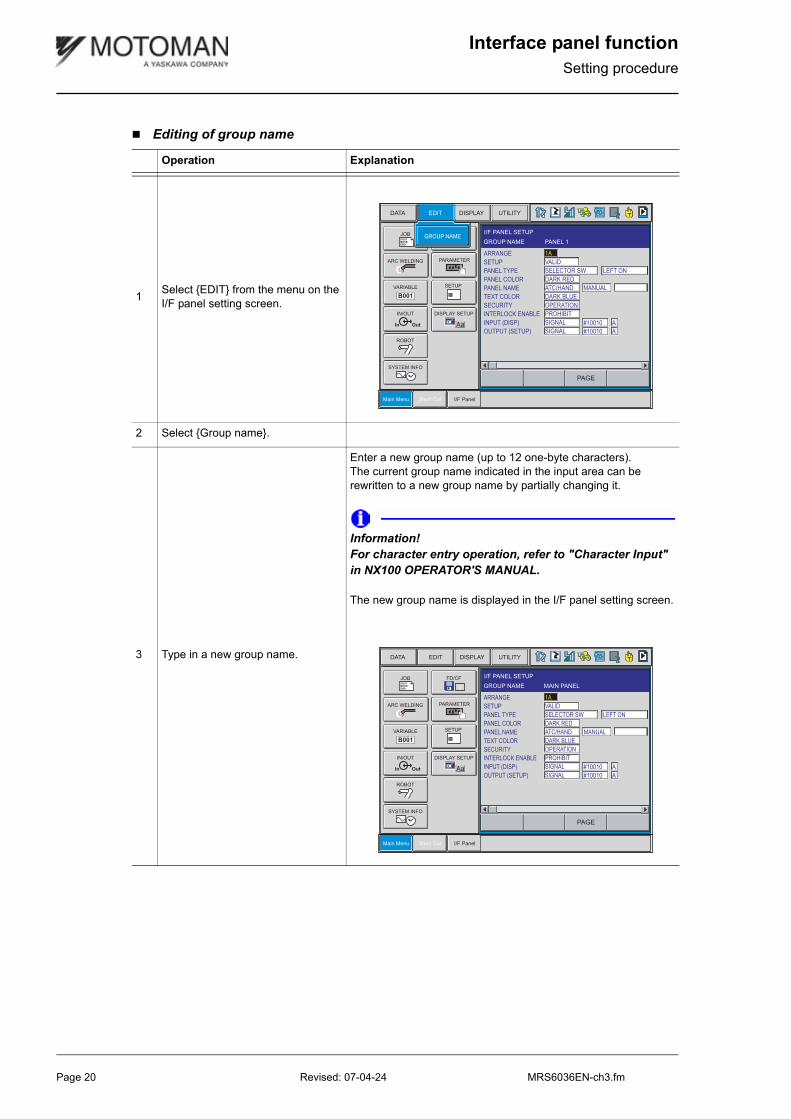
! Editing of group name
Operation Explanation
1 Select {EDIT} from the menu on the I/F panel setting screen.
2 Select {Group name}.
3 Type in a new group name.
Enter a new group name (up to 12 one-byte characters).The current group name indicated in the input area can be rewritten to a new group name by partially changing it.
Information!For character entry operation, refer to "Character Input" in NX100 OPERATOR'S MANUAL.
The new group name is displayed in the I/F panel setting screen.
I/F PANEL SETUPGROUP NAME PANEL 1
#10010#10010
AA
DATA EDIT DISPLAY UTILITY
DOUTMOVEEND
B001
In Out
CF
Aa
Main Menu Short Cut I/F Panel
GROUP NAME
SETUP
JOB
ARC WELDING
VARIABLE
IN/OUT
ROBOT
SYSTEM INFO
PARAMETER
DISPLAY SETUP
PAGE
ARRANGESETUPPANEL TYPEPANEL COLORPANEL NAMETEXT COLORSECURITYINTERLOCK ENABLEINPUT (DISP)OUTPUT (SETUP)
1AVALIDSELECTOR SWDARK REDATC/HANDDARK BLUEOPERATIONPROHIBITSIGNALSIGNAL
LEFT ON
MANUAL
I/F PANEL SETUPGROUP NAME MAIN PANEL
#10010#10010
AA
DATA DISPLAY UTILITYEDIT
DOUTMOVEEND
B001
In Out
CF
Aa
Main Menu Short Cut I/F Panel
FD/CF
SETUP
JOB
ARC WELDING
VARIABLE
IN/OUT
ROBOT
SYSTEM INFO
PARAMETER
DISPLAY SETUP
PAGE
ARRANGESETUPPANEL TYPEPANEL COLORPANEL NAMETEXT COLORSECURITYINTERLOCK ENABLEINPUT (DISP)OUTPUT (SETUP)
1AVALIDSELECTOR SWDARK REDATC/HANDDARK BLUEOPERATIONPROHIBITSIGNALSIGNAL
LEFT ON
MANUAL

MRS6036EN-ch3.fm Revised: 07-04-24 Page 21
Interface panel functionSetting procedure
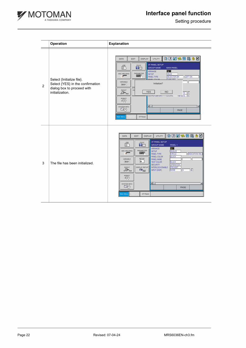
! Initialization of set dataPerform the following procedures to completely initialize the data which have been set.
4 Press {I/F PANEL} to display the I/F PANEL screen.
The new group name is displayed in the I/F panel setting screen.
Operation Explanation
1 Select {DATA} from the menu on the I/F panel setting screen.
Operation Explanation
Short CutMain Menu I/F Panel
I/F PANEL
DATA EDIT DISPLAY UTILITY
=> MOVJ VJ=100.00
Panel 2 Panel 3 Panel 4 Panel 5MAIN PANEL
OPERATIONPROH PERMPROH PERM
0 0
HIT COUNT TYPE OF VEHICLE
WELD ON
COUT-UP NO. TYPE OFVEHICLE
PRECEDING
TYPE OFVEHICLE
PRECEDING
COOL WATERERR
COOL WATERERR
WELDALLOWED
WELDALLOWED
PLAY MODE HOLDTEACH MODEOPERATIONREADY
OPERATIONREADY
PLAY MODESELECT
PLAY MODESELECT
HOLDTEACH MODESELECT
TEACH MODESELECT
0 0
COOL WATERERR RESET
COOL WATERERR RESET
STOP WATERSOLENOID
OPEN
STOP WATERSOLENOID
OPEN
ATC/TOOLMNL OPRTNALLOWED
ATC/TOOLMNL OPRTNALLOWED
SHUTTLE OFF-INTRFRNC
SHUTTLE OFF-INTRFRNC
TIMER ERRRESET
TIMER ERRRESET
COOL WATERSWITCH
COOL WATERSWITCH
OPERATIONORIGINALPOSITION
OPERATIONORIGINALPOSITION
I/F PANEL SETUPGROUP NAME MAIN PANEL
#10010#10010
AA
DISPLAY UTILITYEDIT
DOUTMOVEEND
B001
In Out
CF
Aa
Main Menu Short Cut I/F Panel
FD/CF
DATA
INITIALIZE FILE
SETUP
ARC WELDING
VARIABLE
IN/OUT
ROBOT
SYSTEM INFO
PARAMETER
DISPLAY SETUP
PAGE
ARRANGESETUPPANEL TYPEPANEL COLORPANEL NAMETEXT COLORSECURITYINTERLOCK ENABLEINPUT (DISP)OUTPUT (SETUP)
1AVALIDSELECTOR SWDARK REDATC/HANDDARK BLUEOPERATIONPROHIBITSIGNALSIGNAL
LEFT ON
MANUAL
Interface panel functionSetting procedure
Page 22 Revised: 07-04-24 MRS6036EN-ch3.fm
2
Select {Initialize file}.Select {YES} in the confirmation dialog box to proceed with initialization.
3 The file has been initialized.
Operation Explanation
I/F PANEL SETUPGROUP NAME MAIN PANEL
#10010#10010
AA
DATA DISPLAY UTILITYEDIT
DOUTMOVEEND
B001
In Out
CF
Aa
Main Menu Short Cut I/F Panel
FD/CF
SETUP
JOB
ARC WELDING
VARIABLE
IN/OUT
ROBOT
SYSTEM INFO
PARAMETER
DISPLAY SETUP
PAGE
ARRANGESETUPPANEL TYPEPANEL COLORPANEL NAMETEXT COLORSECURITYINTERLOCK ENABLEINPUT (DISP)OUTPUT (SETUP)
1AVALIDSELECTOR SWDARK RED
DARK BLUEOPERATIONPROHIBITSIGNALSIGNAL
LEFT ON
Initialize?
NOYES
I/F PANEL SETUPGROUP NAME PANEL 1
A
DATA DISPLAY UTILITYEDIT
DOUTMOVEEND
B001
In Out
CF
Aa
Main Menu Short Cut I/F Panel
FD/CF
SETUP
JOB
ARC WELDING
VARIABLE
IN/OUT
ROBOT
SYSTEM INFO
PARAMETER
DISPLAY SETUP
PAGE
ARRANGESETUPPANEL TYPEPANEL COLORPANEL NAMETEXT COLORSECURITYINTERLOCK ENABLEINPUT (DISP)
1AINVALIDCIRCLEBLACK
BLACKOPERATIONPROHIBITNONE
INDICATION ONL

MRS6036EN-ch3.fm Revised: 07-04-24 Page 23
Interface panel functionDetails on interface panel setting items
3.2 Details on interface panel setting itemsThe following describe details on the setting items of the Interface panel screen.Refer to them as required when setting the Interface panel data.
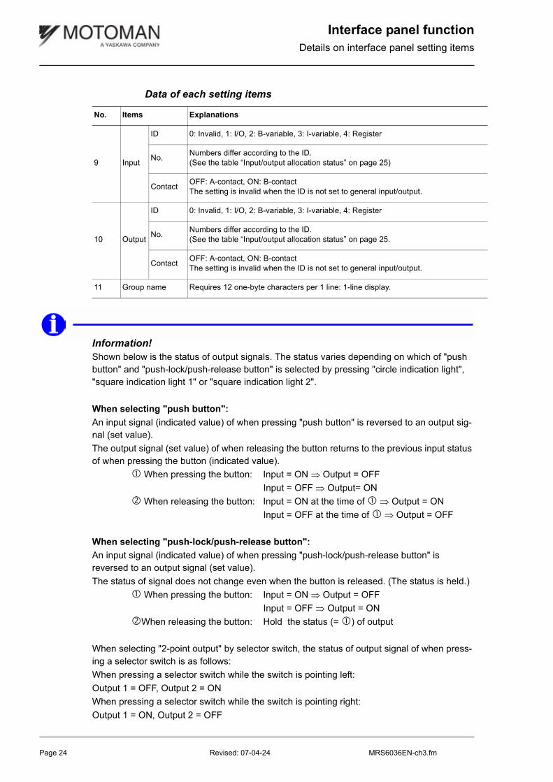
Data of each setting items
No. Items Explanations
1 Arrangement 32 positions in total: 1A to 4H
2 Setup
0: INVALID, 1: VALIDVALID ⇒ INVALID: the setup status can be changed from Valid to Invalid without conditions.INVALID ⇒ VALID: When the set parameter is OK after checking, the status can be changed from Invalid to Valid. The following setting is required for VALID status: <When Icon type is circle, square or selector switch> Input: I/O Output: none or within the range of general output signals <When Icon type is counter> Input: B-variable, I-variable, or register <When Icon type is preset counter> Input: B-variable, I-variable, or register Output: B-variable, I-variable, or register * If the setting item is edited in the Valid status, the status becomes Invalid.
3 Panel type
0:2:
4:
6:8:
10:12:16:18:
Circle indication light (display only)Circle indication light (push-lock/push-release button)Square indication light1 (push button)
Square indication light2 (display only)Square indication light2 (push-lock/push-release button)Selector switch (right: ON)Selector switch (panel operation)Counter (3-digit display)Preset counter (3-digit display)
1:3:
5:
7:9:
11:
17:19:
Circle indication light (push button)Square indication light1 (display only)
Square indication light1 (push-lock/push-release button)Square indication light2 (push button)Selector switch (left: ON)
Selector switch (2-point output)
Counter (6-digit display)Preset counter (6-digit display)
4 Panel color
0: Black, 1: Blue, 2: Green, 3: Sky blue, 4: Red, 5: Purple, 6: Yellow, 7: White, 8: Light gray, 9: Dark blue, 10: Dark green, 11: Dark sky blue, 12: Dark red, 13: Dark purple, 14: Dark yellow, 15: Dark gray, 16: Orange
5 Panel name 10 one-byte characters for one lineThree lines can be indicated at maximum.
6 Text color
0: Black, 1: Blue, 2: Green, 3: Sky blue, 4: Red, 5: Purple, 6: Yellow, 7: White, 8: Light gray, 9: Dark blue, 10: Dark green, 11: Dark sky blue, 12: Dark red, 13: Dark purple, 14: Dark yellow, 15: Dark gray, 16: Orange
7 Security 0: Operation mode, 1: Editing mode, 2: Management mode
8 Interlock enable 0: Prohibited, 1: Permitted
Interface panel functionDetails on interface panel setting items
Page 24 Revised: 07-04-24 MRS6036EN-ch3.fm
Information!Shown below is the status of output signals. The status varies depending on which of "push button" and "push-lock/push-release button" is selected by pressing "circle indication light", "square indication light 1" or "square indication light 2".
When selecting "push button":An input signal (indicated value) of when pressing "push button" is reversed to an output sig-nal (set value).The output signal (set value) of when releasing the button returns to the previous input status of when pressing the button (indicated value).
# When pressing the button: Input = ON ⇒ Output = OFF Input = OFF ⇒ Output= ON
$ When releasing the button: Input = ON at the time of # ⇒ Output = ON Input = OFF at the time of # ⇒ Output = OFF
When selecting "push-lock/push-release button":An input signal (indicated value) of when pressing "push-lock/push-release button" is reversed to an output signal (set value).The status of signal does not change even when the button is released. (The status is held.)
# When pressing the button: Input = ON ⇒ Output = OFF Input = OFF ⇒ Output = ON
$When releasing the button: Hold the status (= #) of output
When selecting "2-point output" by selector switch, the status of output signal of when press-ing a selector switch is as follows:When pressing a selector switch while the switch is pointing left:Output 1 = OFF, Output 2 = ONWhen pressing a selector switch while the switch is pointing right:Output 1 = ON, Output 2 = OFF
9 Input
ID 0: Invalid, 1: I/O, 2: B-variable, 3: I-variable, 4: Register
No. Numbers differ according to the ID.(See the table �Input/output allocation status� on page 25)
Contact OFF: A-contact, ON: B-contactThe setting is invalid when the ID is not set to general input/output.
10 Output
ID 0: Invalid, 1: I/O, 2: B-variable, 3: I-variable, 4: Register
No. Numbers differ according to the ID.(See the table �Input/output allocation status� on page 25.
Contact OFF: A-contact, ON: B-contactThe setting is invalid when the ID is not set to general input/output.
11 Group name Requires 12 one-byte characters per 1 line: 1-line display.
Data of each setting items
No. Items Explanations

MRS6036EN-ch3.fm Revised: 07-04-24 Page 25
Interface panel functionDetails on interface panel setting items
See the following table "Input/output allocation status " when allocating input/output signals.
Information!The table above describes the status of input/output allocation on I/F panel. Don�t refer to this allocation table when allocating input/output signals for concurrent I/O pro-gram.
Input/output allocation status
ID Items Range Input allocation
Output allocation Icon type
1
General input
#00010 to #01287 (1024 signals) enable disable Circle/Square indication light
Selector switch
General output
#10010 to #11287 (1024 signals) enable enable Circle/Square indication light
Selector switch
External input
#20010 to #21287 (1024 signals) enable disable Circle/Square indication light
Selector switch
External output
#30010 to #31287 (1024 signals) enable disable Circle/Square indication light
Selector switch
Special input
#40010 to #40807 (640 signals) enable disable Circle/Square indication light
Selector switch
Special output
#50010 to #51007 (800 signals) enable disable Circle/Square indication light
Selector switch
I/F panel #60010 to #60647(512 signals) enable enable Circle/Square indication light
Selector switch
Auxiliary relay
#70010 to #79997 (7992 signals) enable disable Circle/Square indication light
Selector switch
Control input
#80010 to #80647 (512 signals) enable disable Circle/Square indication light
Selector switch
Pseudo input
#82010 to #82127 (96 signals) enable disable Circle/Square indication light
Selector switch
DL input #22010 to #23287 (1024 signals) enable disable Circle/Square indication light
Selector switch
DL output #32010 to #33287 (1024 signals) enable disable Circle/Square indication light
Selector switch
2 B-variable B000 to B099(100 signals)
enable - Counter
enable enable Preset counter
3 I-variable I000 to I099(100 signals)
enable - Counter
enable enable Preset counter
4 Register M000 to M499(500 signals)
enable - Counter
enable enable Preset counter

Interface panel functionDetails on interface panel setting items
Page 26 Revised: 07-04-24 MRS6036EN-ch3.fm
The following table "Touch panel I/F" describes the the buttons corresponding to icon types.See the table when setting icon types.
Touch panel I/F
No. Items Icon Icon type
0, 1, 2 Circle indication light ON
OFF
Indicates the status of allocated signals.
The light turns on when the status of input signal (indicated value) is ON, whereas it turns off when OFF.
3, 4, 5 Square indication light1
ON
OFF
Indicates the status of allocated signals.
The light turns on when the status of input signal (indicated value) is ON, whereas it turns off when OFF.
6, 7, 8 Square indication light2 ON
OFF
Indicates the status of allocated signals.
The light turns on when the status of input signal (indicated value) is ON, whereas it turns off when OFF.
9, 10, 11, 12 Selector switch
Indicates the status of allocated signals.
When a selector switch is set to "left: ON" or "2-point output):The switch points left when the status of input signal (indicated value) is ON, whereas it points right when OFF.
When a selector switch is set to "right: ON":The switch points right when the status of input signal (indicated value) is ON, whereas it points left when OFF.

MRS6036EN-ch3.fm Revised: 07-04-24 Page 27
Interface panel functionDetails on interface panel setting items
16, 17, 18, 19
Counter (3 digits)Counter (6 digits)
Indicates the allocated variables or registers.
* The BG color of the preset counter is white.
Touch panel I/F
No. Items Icon Icon type
Interface panel functionDetails on interface panel setting items
Page 28 Revised: 07-04-24 MRS6036EN-ch3.fm

MRS6036EN-ch4.fm Revised: 07-04-24 Page 29
Interface panel function
4. Save and load of set dataSet the security level to "Management" mode. (See �Editing of security� on page 18)
Operation Explanation
1 Select {FD/PC CARD} under the main menu.
2 Select {SAVE} or {LOAD}.
3 Move the cursor to "SYSTEM DATA" and press [SELECT].
4 Move the cursor to "I/F PANEL DATA" and press [SELECT].
5 Press [ENTER].
6 Move the cursor to "YES" and press [SELECT].

Interface panel function
Page 30 Revised: 07-04-24 MRS6036EN-ch4.fm
MRS6036EN-ch5.fm Revised: 07-04-24 Page 31
Interface panel function
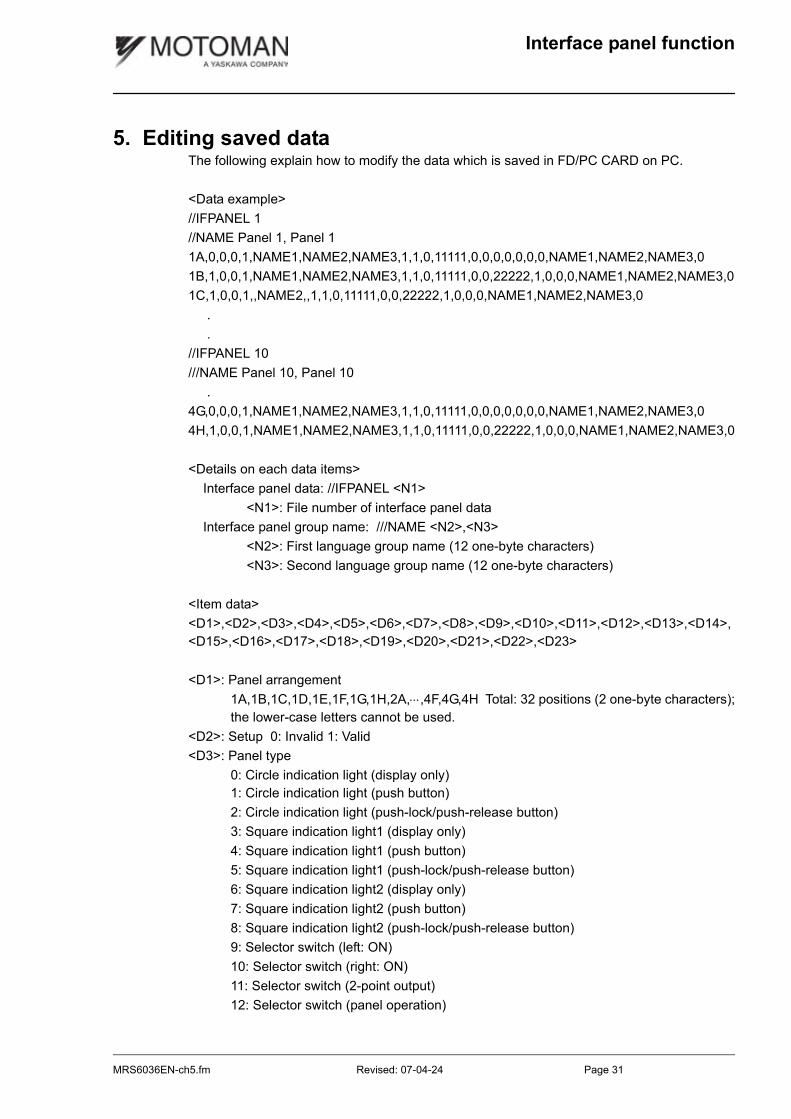
5. Editing saved dataThe following explain how to modify the data which is saved in FD/PC CARD on PC.
<Data example>//IFPANEL 1//NAME Panel 1, Panel 11A,0,0,0,1,NAME1,NAME2,NAME3,1,1,0,11111,0,0,0,0,0,0,0,NAME1,NAME2,NAME3,01B,1,0,0,1,NAME1,NAME2,NAME3,1,1,0,11111,0,0,22222,1,0,0,0,NAME1,NAME2,NAME3,01C,1,0,0,1,,NAME2,,1,1,0,11111,0,0,22222,1,0,0,0,NAME1,NAME2,NAME3,0 . .//IFPANEL 10///NAME Panel 10, Panel 10 .4G,0,0,0,1,NAME1,NAME2,NAME3,1,1,0,11111,0,0,0,0,0,0,0,NAME1,NAME2,NAME3,04H,1,0,0,1,NAME1,NAME2,NAME3,1,1,0,11111,0,0,22222,1,0,0,0,NAME1,NAME2,NAME3,0
<Details on each data items> Interface panel data: //IFPANEL <N1>
<N1>: File number of interface panel data Interface panel group name: ///NAME <N2>,<N3>
<N2>: First language group name (12 one-byte characters)<N3>: Second language group name (12 one-byte characters)
<Item data><D1>,<D2>,<D3>,<D4>,<D5>,<D6>,<D7>,<D8>,<D9>,<D10>,<D11>,<D12>,<D13>,<D14>,<D15>,<D16>,<D17>,<D18>,<D19>,<D20>,<D21>,<D22>,<D23>
<D1>: Panel arrangement1A,1B,1C,1D,1E,1F,1G,1H,2A,⋅⋅⋅,4F,4G,4H Total: 32 positions (2 one-byte characters);the lower-case letters cannot be used.
<D2>: Setup 0: Invalid 1: Valid<D3>: Panel type
0: Circle indication light (display only)1: Circle indication light (push button)2: Circle indication light (push-lock/push-release button)3: Square indication light1 (display only)4: Square indication light1 (push button)5: Square indication light1 (push-lock/push-release button)6: Square indication light2 (display only)7: Square indication light2 (push button)8: Square indication light2 (push-lock/push-release button)9: Selector switch (left: ON)10: Selector switch (right: ON)11: Selector switch (2-point output)12: Selector switch (panel operation)
Interface panel function
Page 32 Revised: 07-04-24 MRS6036EN-ch5.fm
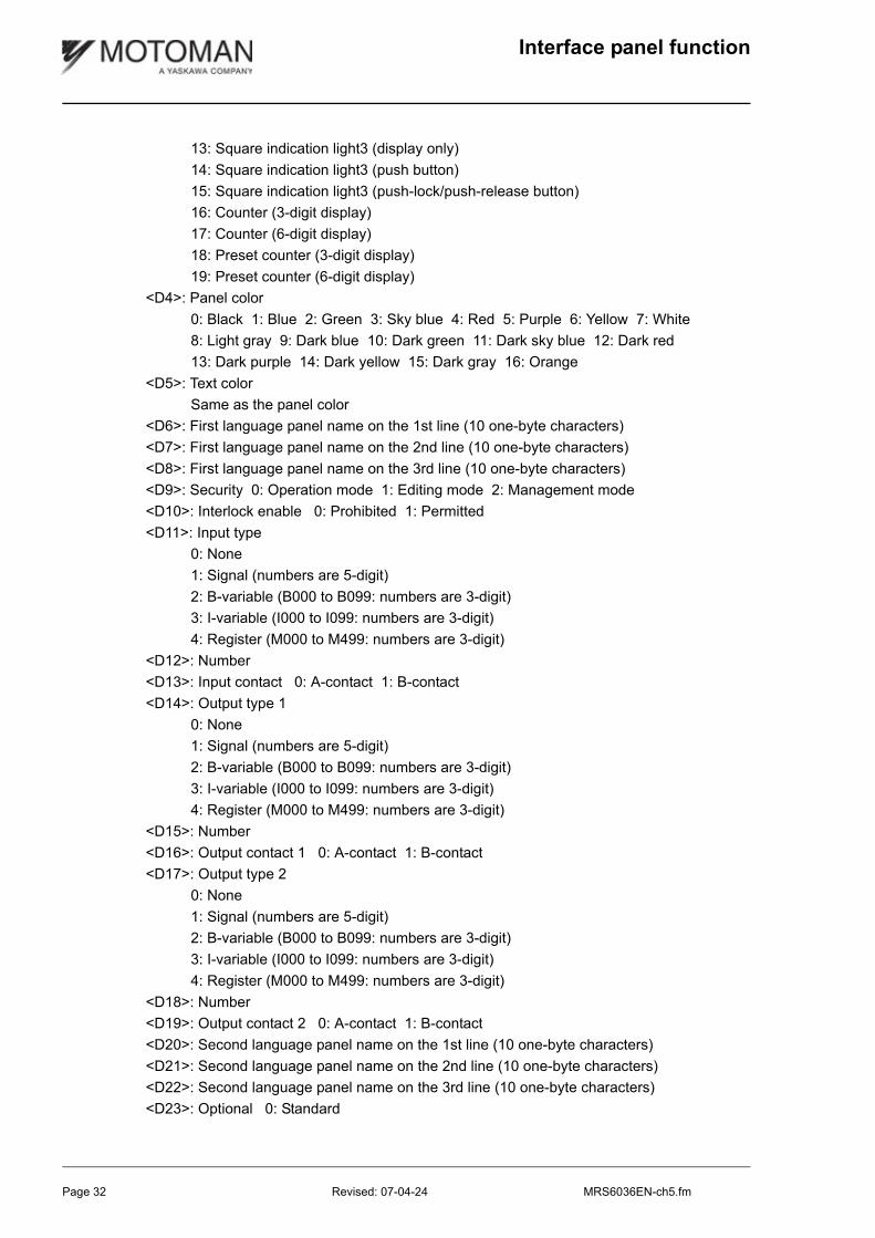
13: Square indication light3 (display only) 14: Square indication light3 (push button) 15: Square indication light3 (push-lock/push-release button) 16: Counter (3-digit display) 17: Counter (6-digit display) 18: Preset counter (3-digit display) 19: Preset counter (6-digit display)<D4>: Panel color 0: Black 1: Blue 2: Green 3: Sky blue 4: Red 5: Purple 6: Yellow 7: White 8: Light gray 9: Dark blue 10: Dark green 11: Dark sky blue 12: Dark red 13: Dark purple 14: Dark yellow 15: Dark gray 16: Orange<D5>: Text color Same as the panel color<D6>: First language panel name on the 1st line (10 one-byte characters)<D7>: First language panel name on the 2nd line (10 one-byte characters)<D8>: First language panel name on the 3rd line (10 one-byte characters)<D9>: Security 0: Operation mode 1: Editing mode 2: Management mode<D10>: Interlock enable 0: Prohibited 1: Permitted<D11>: Input type 0: None 1: Signal (numbers are 5-digit) 2: B-variable (B000 to B099: numbers are 3-digit) 3: I-variable (I000 to I099: numbers are 3-digit) 4: Register (M000 to M499: numbers are 3-digit)<D12>: Number<D13>: Input contact 0: A-contact 1: B-contact<D14>: Output type 1 0: None 1: Signal (numbers are 5-digit) 2: B-variable (B000 to B099: numbers are 3-digit) 3: I-variable (I000 to I099: numbers are 3-digit) 4: Register (M000 to M499: numbers are 3-digit)<D15>: Number<D16>: Output contact 1 0: A-contact 1: B-contact<D17>: Output type 2 0: None 1: Signal (numbers are 5-digit) 2: B-variable (B000 to B099: numbers are 3-digit) 3: I-variable (I000 to I099: numbers are 3-digit) 4: Register (M000 to M499: numbers are 3-digit)<D18>: Number<D19>: Output contact 2 0: A-contact 1: B-contact<D20>: Second language panel name on the 1st line (10 one-byte characters)<D21>: Second language panel name on the 2nd line (10 one-byte characters)<D22>: Second language panel name on the 3rd line (10 one-byte characters)<D23>: Optional 0: Standard

MRS6036EN-ch5.fm Revised: 07-04-24 Page 33
Interface panel function
Warning!% Syntax error will occur when inserting line feeds into the data "Data example".% Syntax error will occur when the number of commas differs from the saved data in FD/
PC card.% Define capital letters for variables.% Wrong signal range or type instruction will make the attribute invalid when loading.% Loading for one item is possible as follow;
//IFPANEL 4///NAME Panel 4, Panel 41A,0,0,0,1,NAME1,NAME2,NAME3,1,1,0,11111,0,0,0,0,0,0,0,NAME1,NAME2,NAME3,0

Interface panel function
Page 34 Revised: 07-04-24 MRS6036EN-ch5.fm

MRS6036EN-ch6.fm Revised: 07-04-24 Page 35
Interface panel functionClearing the status of signals
6. Parameters
6.1 Clearing the status of signalsBy setting parameters, input/output signals at the time of power supply ON or mode change can be set to "hold" or "clear".The possible settings and the timing of status signal settings are as follows:
*Notice that auxiliary relay signals have different set values of parameters from general output signals or I/F panel signals.
"Hold" and "Clear" of the status of signlas are defined as follows:"Hold" means to keep the status of the previous one at the time of when the power supply is turned OFF or the mode is changed."Clear" means to turn the status of signals into OFF regardless of the previous status at the time of when the power supply is turned OFF or the mode is changed.
! Status of general output signals at mode changeBy setting parameters from S4C032 to S4C039, it allows to set the status of general output signals (#10010 to #11287) at the time of when changing mode. For the parameter settings, refer to the table below.
Signals Timing of setting the status of signals Parameters Set values
General output signals Mode change S4C032 to S4C039 0: Hold / 1: Clear
General output signals Power supply ON S2C187 0: Hold / 1: Clear
Auxiliary relay signals Power supply ON S4C040 to S4C055 0: Clear / 1: Hold
I/F panel signals Power supply ON S4C330 to S4C333 0: Hold / 1: Clear
Parameters General output signals Set values Explanation
S4C032 #10010 to #10167
(Bit specification)
0: Hold, 1: Clear
When a bit specification is set to "1", the status of general output signals will be cleared at the time of changing mode.(Bit specification is to be set by a series of 8 signals.)
S4C033 #10170 to #10327
S4C034 #10330 to #10487
S4C035 #10490 to #10647
S4C036 #10650 to #10807
S4C037 #10810 to #10967
S4C038 #10970 to #11127
S4C039 #11130 to #11287

Interface panel functionClearing the status of signals
Page 36 Revised: 07-04-24 MRS6036EN-ch6.fm
! Status of general output signals at power supply ONBy setting parameter S2C187, it allows to set the status of general output signals (#10010 to #11287) at the time of when turning the power supply ON. For the parameter setting, refer to the table below.
! Status of auxiliary relay signals at power supply ONBy setting parameters from S4C040 to S4C055, it allows to set the status of auxiliary relay signals (#70010 to #79997) at the time of when turning the power supply ON. For the para-meter settings, refer to the table below.
Parameters General output signals Set values Explanation
S2C187 #10010 to #11287 0: Hold, 1: Clear
When S2C187 is set to "1", the status of general output signals will be cleared at the time of power supply ON.(All signals are to be set together.)
Parameters Auxiliary relay signals Set values Explanation
S4C040 #70010 to #70647
(Bit specification)
0: Clear,1: Hold
When a bit specification is set to "1", the status of auxiliary relay signals will be held at the time of power supply ON.(Bit specification is to be set by a series of 32 signals.)
S4C041 #70650 to #71287
S4C042 #71290 to #71927
S4C043 #71930 to #72567
S4C044 #72570 to #73207
S4C045 #73210 to #73847
S4C046 #73850 to #74487
S4C047 #74490 to #75127
S4C048 #75130 to #75767
S4C049 #75770 to #76407
S4C050 #76410 to #77047
S4C051 #77050 to #77687
S4C052 #77690 to #78327
S4C053 #78330 to #78967
S4C054 #78970 to #79607
S4C055 #79610 to #79997

MRS6036EN-ch6.fm Revised: 07-04-24 Page 37
Interface panel functionAllocation of general input signals to interface panel screens
! Status of I/F panel signals at power supply ONBy setting parameters from S4C330 to S4C333, it allows to set the status of I/F panel signals (#60010 to #60647) at the time of when turning the power supply ON. For the parameter set-tings, refer to the table below.
6.2 Allocation of general input signals to interface panel screensBy setting general input signal numbers to parameters from S4C350 to S4C360, general input signals can be allocated to interface panel screens. For the parameter settings, refer to the table below.
Parameters I/F panel signals Set values Explanation
S4C330 #60010 to #60167
(Bit specification)
0: Hold, 1: Clear
When a bit specification is set to "1", the status of I/F panel signals will be cleared at the time of power supply ON.(Bit specification is to be set by a series of 8 signals.)
S4C331 #60170 to #60327
S4C332 #60330 to #60487
S4C333 #60490 to #60647
Parameters Corresponding panel screens Set values Explanation
S4C350 NONE
0: No function
1 to 1024 (Integral number):General input signal numbers
Allocates the general input signals set for parameters to the panel screens corresponded to the parameters.
S4C351 Panel 1
S4C352 Panel 2
S4C353 Panel 3
S4C354 Panel 4
S4C355 Panel 5
S4C356 Panel 6
S4C357 Panel 7
S4C358 Panel 8
S4C359 Panel 9
S4C360 Panel 10

Interface panel functionAllocation of general input signals to interface panel screens
Page 38 Revised: 07-04-24 MRS6036EN-ch6.fm
! Notification of the status of general input signals
Information!In the cases below, the [I/F Panel] button flashes in the lower left of the display notifying the "ON" status of the general input signals set for the parameters.
% The case when the Interface panels are unable to get activated (during imputing characters or numeric values) when the general input signals set for the parameters turn ON.
% The case when a page button of the corresponding panel is not shown when the general input signals set for the parameters turn ON.
Operation Explanation
1
Set general input signal numbers to the parameters from S4C350 to S4C360. (Set values are available from 1 to 1024)
When the general input signal set to the parameter turns ON, the Interface panel gets activated automatically and the corresponding panel screen appears.If there are several corresponding screens, the panel of smaller number appears on the display.However, when the signal set to S4C350 (which has no corresponding panel) turns ON, the panel screen of the previous one appears on the display.
When the signals set from S4C351 to S4C360 turn ON, the page button (on which the group name is indicated) changes its color in the corresponding panel.

Notes

Specifications may be subject to change without notice
MOTOMAN Group companies:
AT MOTOMAN robotec GmbHAm concorde Park 1, B6/108-110, AT-2320 Schwechat-Wien, AustriaPhone +43-1-707-9324-15
CZ MOTOMAN robotec Czech s.r.o.Jeremiasova 1422/7b, CZ-155 00 Prague, Czech RepublicPhone +420-251-618-430
DE MOTOMAN robotec GmbHIm Katzenforst 2, DE-61476 Kronberg/Taunus, GermanyPhone: +49-6173-60-77-30
DK MOTOMAN Robotics Europe ABAnelystparken 47A, DK-8381 Tilst, DenmarkPhone: +45-7022-2477
ES MOTOMAN Robotics Iberica S.L.Avenida Marina 56, Parcela 90, ES-08830 St. Boi de Llobregat (Barcelona), SpainPhone: +34-93-6303478
FI MOTOMAN Robotics Finland OYMessinkikatu 2, FI-20380 Turku, FinlandPhone: +358-403000600
FR MOTOMAN Robotics SARLRue Nungesser et Coli, D2A Nantes-Atlantique, FR-44860 Saint-Aignan-de-Grand-Lieu, FrancePhone: +33-2-40131919
IT MOTOMAN Robotics Italia SRLVia Emilia 1420/16, IT-41100 Modena, ItalyPhone: +39-059-280496
NL MOTOMAN benelux B.VZinkstraat 70, NL-4823 AC Breda, NetherlandsPhone: +31-76-5302305
PT MOTOMAN Robotics Iberica S.L.Z. Ind. Aveiro Sul, Lote 21, N. S. Fátima, PT-3810 Aveiro, PortugalPhone: +351-234 943 900
SE MOTOMAN Robotics Europe ABBox 504, SE-385 25 Torsås, SwedenPhone: +46-480-417800
SI MOTOMAN robotec d.o.o.Lepovce 23, SI-1310 Ribnica, SloveniaPhone: +386-1-8372410
SI RISTRO d.o.o.Lepovce 23, SI-1310 Ribnica, SloveniaPhone: +386-61-8372410
UK MOTOMAN Robotics UK LtdJohnson Park, Wildmere Road, Banbury, Oxon OX16 3JU, Great BritainPhone: +44-1295-272755
Distributors:
CZ Hadyna International spol. s.r.o.Ostrava-Marianske Hory +420 596 622 636
CZ SP-Tech s.r.o.Nymburk +420 325 515 105
CH Messer Schweisstechnik AGDällikon +41-1-8471717
GR Kouvalias Robotics Avlona Attica +30-22950 42902
HU Rehm Hegesztéstechnika KftBudapest +36-30-9510065
IL KNT Engineering LtdBeit Shemesh +972-2-9905882
IL Uniweld LtdYavne +972-8-9328080
NO Optimove asLierstranda +47-32240600
PL Rywal-RHC Sp.z.o.oTorun +48 56 66 93 800
RU Weber ComechanicsMoscow +7 495 105 88 87
TR Teknodrom Robotics & Automation INCGebze/Kocaeli +90 262 678 8820
ZA Robotic Systems SA PTY LtdJohannesburg +27-11-6083182
MOTOMAN Headquarters
MOTOMAN Robotics Europe ABBox 4004, SE-390 04 Kalmar, SwedenPhone: +46-480-417800, Fax: [email protected]
MOTOMAN robotec GmbHKammerfeldstraße 1, DE-85391 Allershausen, GermanyPhone: +49-8166-90-0, Fax: [email protected]


![[MS-IPHTTPS]: IP over HTTPS (IP-HTTPS) Tunneling Protocol](https://static.fdocuments.in/doc/165x107/627be39a59665752362cd62d/ms-iphttps-ip-over-https-ip-https-tunneling-protocol.jpg)


![[MS-IPHTTPS]: IP over HTTPS (IP-HTTPS) Tunneling Protocol€¦ · IP over HTTPS (IP-HTTPS) Tunneling Protocol Intellectual Property Rights Notice for Open Specifications Documentation](https://static.fdocuments.in/doc/165x107/5f5d18b22a82be0e3640e86d/ms-iphttps-ip-over-https-ip-https-tunneling-protocol-ip-over-https-ip-https.jpg)