HT-SB600 Operation Manual - Sharp USAfiles.sharpusa.com/.../Audio/Manuals/aud_man_HTSB600.pdf ·...
24
Note: This product is recommended for flat panel TV (LCD and plasma). OPERATION MANUAL Thank you for purchasing this SHARP product. To obtain the best performance from this product, please read this manual carefully. It will guide you in operating your SHARP product. TINSEA352AWZZ Printed in Malaysia 10K R KI 1 MODEL HT-SB600 SOUND BAR SYSTEM ENGLISH HT-SB600 Sound Bar system consisting of HT-SB600 (main unit), CP-SB600 (sound bar) and CP-SW600 (subwoofer). Please confirm that only the following accessories are included. AM Loop Antenna (QANTLA004AWZZ) Remote Control (RRMCGA248AWSA) Stand x 4 (GITAUA004AW01) FM Antenna (92LFANT1535A) Wall Mount Angle x 2 (LANGKA167AWFW) Pattern Paper (TCAUHA025AWZZ) Speaker Wire (QCNWHA042AW01) Accessories
Transcript of HT-SB600 Operation Manual - Sharp USAfiles.sharpusa.com/.../Audio/Manuals/aud_man_HTSB600.pdf ·...

HT-SB600_Front EN.fm 2011January25
HT-SB600
INPUT
TIMER
ARC
TV
CLOCK
DIMMERTUNING
TUNER(BAND)
EQUALIZER X-BASS
CHANNEL VOL
VOL
VOL
INPUT
TV
BASS/TREBLE MUTE
TIMER
LINE
DIGITAL
SUBWOOFER LEVEL
PRESET
PRESET
CENTER LEVEL
1 2
1 2 1 2
3HDMI
Note:This product is recommended for flat panel TV (LCD and plasma).
OPERATION MANUAL
Thank you for purchasing this SHARP product. To obtain the best performance from this product, pleaseread this manual carefully. It will guide you in operating your SHARP product.
TINSEA352AWZZPrinted in Malaysia10K R KI 1
MODEL
HT-SB600SOUND BAR SYSTEM
ENGLISH
HT-SB600 Sound Bar system consisting of HT-SB600 (main unit), CP-SB600 (sound bar) and CP-SW600(subwoofer).
Please confirm that only the following accessories are included.
AM Loop Antenna(QANTLA004AWZZ)
Remote Control(RRMCGA248AWSA)
Stand x 4(GITAUA004AW01)
FM Antenna(92LFANT1535A)
Wall Mount Angle x 2(LANGKA167AWFW)
Pattern Paper(TCAUHA025AWZZ)
Speaker Wire(QCNWHA042AW01)
Accessories

917654321
9
2011 January 27 HT-SB600
E-1
NOTEThis equipment has been tested and found to comply withthe limits for a Class B digital device, pursuant to Part 15of the FCC Rules. These limits are designed to providereasonable protection against harmful interference in aresidential installation. This equipment generates, uses,and can radiate radio frequency energy and, if not installedand used in accordance with the instructions, may causeharmful interference to radio communications. However,there is no guarantee that interference will not occur in aparticular installation. If this equipment does causeharmful interference to radio or television reception, whichcan be determined by turning the equipment off and on,the user is encouraged to try to correct the interference byone or more of the following measures:● Reorient or relocate the receiving antenna.● Increase the separation between the equipment and
receiver.● Connect the equipment into an outlet on a circuit
different from that to which the receiver is connected.● Consult the dealer or an experienced radio/TV
technician for help.
WARNINGFCC Regulations state that any unauthorized changes ormodifications to this equipment not expressly approved bythe manufacturer could void the user’s authority to operatethis equipment.
Electricity is used to perform many useful functions, but itcan also cause personal injuries and property damage ifimproperly handled. This product has been engineeredand manufactured with the highest priority on safety.However, improper use can result in electric shock and/orfire. In order to prevent potential danger, please observethe following instructions when installing, operating andcleaning the product. To ensure your safety and prolongthe service life of this product, please read the followingprecautions carefully before use.1) Read these instructions.2) Keep these instructions.3) Heed all warnings.4) Follow all instructions.5) Do not use this apparatus near water.6) Clean only with dry cloth.7) Do not block any ventilation openings. Install in
accordance with the manufacturer’s instructions.
Special Notes
CAUTION: TO REDUCE THE RISK OF ELECTRICSHOCK, DO NOT REMOVE COVER (OR BACK).NO USER-SERVICEABLE PARTS INSIDE. REFERSERVICING TO QUALIFIED SERVICE PERSONNEL.Explanation of Graphical Symbols:
The lightning flash with arrowhead symbol,within an equilateral triangle, is intended toalert the user to the presence ofuninsulated “dangerous voltage” within theproduct’s enclosure that may be ofsufficient magnitude to constitute a risk ofelectric shock to persons.
The exclamation point within an equilateraltriangle is intended to alert the user to thepresence of important operating andmaintenance (servicing) instructions in theliterature accompanying the appliance.
WARNING: TO REDUCE THE RISK OF FIRE ORELECTRIC SHOCK, DO NOT EXPOSE THISAPPLIANCE TO RAIN OR MOISTURE.
FOR YOUR RECORDSFor your assistance in reporting this unit in case of lossor theft, please record below the model number andserial number which are located on the rear of the unit.Please retain this information.
Model number ........................................................Serial number ........................................................Date of purchase ........................................................Place of purchase ........................................................
Note to CATV system installer:This reminder is provided to call the CATV systeminstaller’s attention to Article 820 of the NationalElectrical Code that provides guidelines for propergrounding and, in particular, specifies that the cableground shall be connected to the grounding system ofthe building, as close to the point of cable entry aspractical.
Manufactured under license under U.S. Patent#: 5,451,942; 5,956,674; 5,974,380; 5,978,762;6,487,535 & other U.S. and worldwide patents issued &pending. DTS and the Symbol are registered trademarks& DTS Digital Surround and the DTS logos aretrademarks of DTS, Inc. Product includes software. © DTS, Inc. All Rights Reserved.
Manufactured under license from Dolby Laboratories.Dolby, Pro Logic, and the double-D symbol aretrademarks of Dolby Laboratories.
HDMI, the HDMI Logo, and High-Definition MultimediaInterface are trademarks or registered trademarks ofHDMI Licensing LLC in the United States and othercountries.
ENERGY STAR® Program Information
Products that have earnedthe ENERGY STAR® aredesigned to protect theenvironment throughsuperior energy efficiency.
ENERGY STAR® is a U.S. registered mark.
Important Safety Instructions

987654321
9E-2
2011 January 27 HT-SB600
8) Do not install near any heat sources such as radiators,heat registers, stoves, or other apparatus (includingamplifiers) that produce heat.
9) Do not defeat the safety purpose of the polarized orgrounding-type plug. A polarized plug has two bladeswith one wider than the other. A grounding type plughas two blades and a third grounding prong. The wideblade or the third prong are provided for your safety. Ifthe provided plug does not fit into your outlet, consult anelectrician for replacement of the obsolete outlet.
10) Protect the power cord from being walked on orpinched particularly at plugs, convenience receptacles,and the point where they exit from the apparatus.
11) Only use attachments/accessories specified by themanufacturer.
13) Unplug this apparatus during lightning storms or whenunused for long periods of time.
14) Refer all servicing to qualified service personnel.Servicing is required when the apparatus has beendamaged in any way, such as power-supply cord orplug is damaged, liquid has been spilled or objectshave fallen into the apparatus, the apparatus has beenexposed to rain or moisture, does not operate normally,or has been dropped.
Additional Safety Information15) Power Sources - This product should be operated only
from the type of power source indicated on the markinglabel. If you are not sure of the type of power supply toyour home, consult your product dealer or local powercompany. For product intended to operate from batterypower, or other sources, refer to the operatinginstructions.
16) Overloading - Do not overload wall outlets, extensioncords, or integral convenience receptacles as this canresult in a risk of fire or electric shock.
17) Object and Liquid Entry - Never push objects of anykind into this product through openings as they maytouch dangerous voltage points or short-out parts thatcould result in a fire or electric shock. Never spill liquidof any kind on the product.
18) Damage Requiring Service - Unplug this product fromthe wall outlet and refer servicing to qualified servicepersonnel under the following conditions:
a) When the AC cord or plug is damaged,b) If liquid has been spilled, or objects have fallen
into the product,c) If the product has been exposed to rain or water,d) If the product does not operate normally by
following the operating instructions. Adjust onlythose controls that are covered by the operatinginstructions as an improper adjustment of othercontrols may result in damage and will oftenrequire extensive work by a qualified technician torestore the product to its normal operation,
e) If the product has been dropped or damaged inany way, and
f) When the product exhibits a distinct change inperformance - this indicates a need for service.
19) Replacement Parts - When replacement parts arerequired, be sure the service technician has usedreplacement parts specified by the manufacturer orhave the same characteristics as the original part.Unauthorized substitutions may result in fire, electricshock, or other hazards.
20) Safety Check - Upon completion of any service orrepairs to this product, ask the service technician toperform safety checks to determine that the product isin proper operating condition.
21) Wall or ceiling mounting - When mounting the producton a wall or ceiling, be sure to install the productaccording to the method recommended by themanufacturer.
22) Power Lines - An outside antenna system should notbe located in the vicinity of overhead power lines orother electric light or power circuits, or where it can fallinto such power lines or circuits. When installing anoutside antenna system, extreme care should be takento keep from touching such power lines or circuits ascontact with them might be fatal.
23) Protective Attachment Plug - The product is equippedwith an attachment plug having overload protection.This is a safety feature. See Instruction Manual forreplacement or resetting of protective device. Ifreplacement of the plug is required, be sure the servicetechnician has used a replacement plug specified bythe manufacturer that has the same overloadprotection as the original plug.
24) Stand - Do not place the product on an unstable cart,stand, tripod or table. Placing the product on anunstable base can cause the product to fall, resultingin serious personal injuries as well as damage to theproduct. Use only a cart, stand, tripod, bracket or tablerecommended by the manufacturer or sold with theproduct. When mounting the product on a wall, be sureto follow the manufacturer's instructions. Use only themounting hardware recommended by themanufacturer.
Important Safety Instructions (continued)
12) Use only with the cart, stand, tripod,bracket, or table specified by themanufacturer, or sold with the apparatus.When a cart is used, use caution whenmoving the cart/apparatus combination toavoid injury from tip-over.

917654321
9
2011 January 27 HT-SB600
E-3
For U.S. customer only
CONSUMER LIMITED WARRANTYSHARP ELECTRONICS CORPORATION warrants to the first consumer purchaser that this Sharp brand product (the "Product"), when ship in its original container, will be free from defective workmanship and materials, and agrees that it will,at its option, either repair the defect or replace the defective Product or part thereof with a new or remanufactured equivalentat no charge to the purchaser for parts or labor for the period(s) set forth below.
This warranty does not apply to any appearance items of the Product nor to the additional excluded item(s) set forth below nor to any Product the exterior of which has been damaged or defaced, which has been subjected to improper voltage or other misuse, abnormal service or handling, or which has been altered or modified in design or construction.
In order to enforce the rights under this limited warranty, the purchaser should follow the steps set forth below and provide proof of purchase to the servicer.
The limited warranty described herein is in addition to whatever implied warranties may be granted to purchasers by law. ALL IMPLIED WARRANTIES INCLUDING THE WARRANTIES OF MERCHANTABILITY AND FITNESS FOR USE ARE LIMITED TO THE PERIOD(S) FROM THE DATE OF PURCHASE SET FORTH BELOW. Some states do not allow limitations on how long an implied warranty lasts, so the above limitation may not apply to you.
Neither the sales personnel of the seller nor any other person is authorized to make any warranties other than those described herein, or to extend the duration of any warranties beyond the time period described herein on behalf of Sharp.
The warranties described herein shall be the sole and exclusive warranties granted by Sharp and shall be the sole and exclusive remedy available to the purchaser. Correction of defects, in the manner and for the period of time described herein, shall constitute complete fulfillment of all liabilities and responsibilities of Sharp to the purchaser with respect to the Product, and shall constitute full satisfaction of all claims, whether based on contract, negligence, strict liability or otherwise.In no event shall Sharp be liable, or in any way responsible, for any damages or defects in the Product which were caused by repairs or attempted repairs performed by anyone other than an authorized servicer. Nor shall Sharp be liable or in any way responsible for any incidental or consequential economic or property damage. Some states do not allow the exclusion of incidental or consequential damages, so the above exclusion may not apply to you.
THIS WARRANTY GIVES YOU SPECIFIC LEGAL RIGHTS. YOU MAY ALSO HAVE OTHER RIGHTS WHICH VARY FROM STATE TO STATE.
Model Specific Section
Your Product Model Number & Description:
Warranty Period for this Product:
Additional Item(s) Excluded from Warranty Coverage (if any):
Where to Obtain Service:
What to do to Obtain Service:
HT-SB600 Sound Bar System
(Be sure to have this information available when you need service for your Product.)
One (1) year parts and labor from the date of purchase.
Non-functional accessories, supplies, and consumable items.
At a Sharp Authorized Servicer located in the United States. To find a location of the nearest Sharp Authorized Servicer, call Sharp toll free at 1-800-BE-SHARP.
Ship prepaid or carry in your Product to a Sharp Authorized Servicer. Be sure to have Proof of Purchase available. If you ship the Product, be sure it is insured and packaged securely.
TO OBTAIN SUPPLY, ACCESSORY OR PRODUCT INFORMATION, CALL 1-800-BE-SHARP
SHARP ELECTRONICS CORPORATIONSharp Plaza, Mahwah, New Jersey 07495-1163

987654321
9E-4
2011 January 27 HT-SB600
● Use the unit on a firm, level surface free from vibration.● Keep the unit away from direct sunlight, strong
magnetic fields, excessive dust, humidity andelectronic/electrical equipment (home computers,facsimiles, etc.) which generate electrical noise.
● Do not place anything on top of the unit.● Do not expose the unit to moisture, to temperatures
higher than 140°F (60°C) or to extremely lowtemperatures.
● If your system does not work properly, disconnect theAC power cord from the AC outlet. Plug the AC powercord back in, and then turn on your system.
● In case of an electrical storm, unplug the unit for safety.● Hold the AC power plug by the head when removing it
from the AC outlet, as pulling the cord can damageinternal wires.
● The AC power plug is used as a disconnect device andshall always remain readily operable.
● Do not remove the outer cover, as this may result inelectric shock. Refer internal service to your localSHARP service facility.
● This unit should only be used within the range of 41°F -95°F (5°C - 35°C).
● SHARP is not responsible for damage due to improperuse. Refer all servicing to a SHARP authorised servicecenter.
Warning:The voltage used must be the same as that specified onthis unit. Using this product with a higher voltage otherthan that which is specified is dangerous and may result ina fire or other type of accident causing damage. SHARPwill not be held responsible for any damage resulting fromuse of this unit with a voltage other than that which isspecified.
The sound level at a given volume setting depends onspeaker efficiency, location and various other factors. It isadvisable to avoid exposure to high volume levels, whichoccurs while turning the unit on with the volume controlsetting up high, or while continually listening at highvolumes.
This unit is fitted with a cooling fan at the rear for improvedcooling. Do not cover the opening in this section with anyobstacles.
Caution:● The unit will get warm while being used. Do not touch
the warm areas of the unit for prolonged periods toavoid injuries.
● This unit is equipped with a special function whichprotects the amplifier circuit from damages. When it isactivated, the sound switch is turned off. In this case,set the unit to the stand-by mode and turn on again.
Precautions
● Please ensure that the equipment is positioned in awell-ventilated area and ensure that there is at least 4" (10 cm) of free space along the sides, top and backof the equipment.
General
4" (10 cm)4" (10 cm) 4" (10 cm)
4" (10 cm)
Volume control
Cooling fan
Cooling fan

917654321
9
2011 January 27 HT-SB600
E-5
Reference page
1. Remote Sensor . . . . . . . . . . . . . . . . . . . . . . . . . . 152. Information Display . . . . . . . . . . . . . . . . . . . . . . . 163. Timer Indicator. . . . . . . . . . . . . . . . . . . . . . . . . . . 204. On/Stand-by Button . . . . . . . . . . . . . . . . . 16, 18, 225. Input Button . . . . . . . . . . . . . . . . . . . . . . . 12, 15, 176. Equalizer Button . . . . . . . . . . . . . . . . . . . . . . 16, 227. Volume Up/Down Button . . . . . . . . . . . . . . . . . . . 16
Reference page
1. AM Indicator . . . . . . . . . . . . . . . . . . . . . . . . . . . . 192. FM Indicator . . . . . . . . . . . . . . . . . . . . . . . . . . . . 183. FM Stereo Indicator . . . . . . . . . . . . . . . . . . . . . . 184. FM Stereo receiving Indicator . . . . . . . . . . . . . . 175. DTS Indicator . . . . . . . . . . . . . . . . . . . . . . . . . . . 176. PCM Indicator. . . . . . . . . . . . . . . . . . . . . . . . . . . . 187. X-BASS Indicator . . . . . . . . . . . . . . . . . . . . . . . . 178. MUTING Indicator . . . . . . . . . . . . . . . . . . . . . . . . 169. Dolby Digital Indicator . . . . . . . . . . . . . . . . . . . . 17
10. Dolby Pro Logic II Indicator . . . . . . . . . . . . . . . . 1711. Audio Return Channel Indicator . . . . . . . . . . . . 17
Controls and indicators
1 2 3
4 5 6 7
Front Panel
AMX-BASS
FMSTDIGITAL ARC
PCMPLMUTING
1 2 3 4 5 6
7 8 9 10 11
AMX-BASS
FMSTDIGITAL ARC
PCMPLMUTING
Display
987654321
9E-6
2011 January 27 HT-SB600
Reference page1. Digital Input Jack. . . . . . . . . . . . . . . . . . . . . . 13, 142. Line Input Jack . . . . . . . . . . . . . . . . . . . . . . . 13, 143. FM 75 Ohms Antenna Jack. . . . . . . . . . . . . . 11, 124. AM Antenna Ground Terminal . . . . . . . . . . . . . . 115. AM Loop Antenna Terminal . . . . . . . . . . . . . . . . 116. Front Speaker Terminal. . . . . . . . . . . . . . . . . . . . 117. Center Speaker Terminal . . . . . . . . . . . . . . . . . . 118. Subwoofer Terminal . . . . . . . . . . . . . . . . . . . . . . 119. HDMI (TV ARC) Output Jack. . . . . . . . . . . . . . . . 12
10. HDMI input Jack. . . . . . . . . . . . . . . . . . . . . . . . . . 1211. Cooling Fan . . . . . . . . . . . . . . . . . . . . . . . . . . . . . . 412. AC Power Cord. . . . . . . . . . . . . . . . . . . . . . . . . . . 11
Controls and indicators (continued)
9
10
11
67
8
2
34
1
5
12
The spec label (*)
The spec label illustration may be different from the actual label used(*) Label is located at the bottom of the unit
Rear Panel
917654321
9
2011 January 27 HT-SB600
E-7
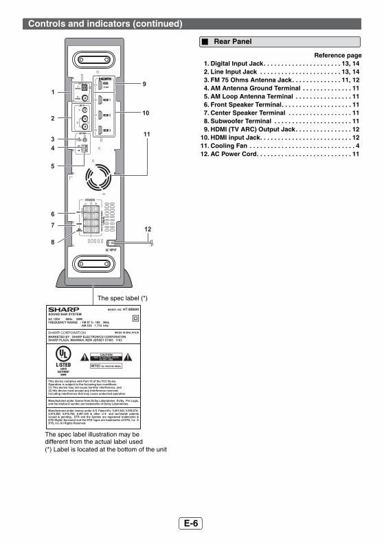
1. Left Front Speaker2. Bass Reflex Duct3. Right Front speaker4. Center Speaker
Reference page5. Right Front Speaker terminal . . . . . . . . . . . . . . . .116. Center Speaker terminal . . . . . . . . . . . . . . . . . . . .117. Left Front Speaker terminal . . . . . . . . . . . . . . . . .11
Reference page
1. Bass Reflect Duct 2. Woofer3. Speaker Terminals . . . . . . . . . . . . . . . . . . . . . . . . 11
Controls and indicators (continued)
Sound Bar
1
2 2
3
4
2
75 6
FRONT VIEW
REAR VIEW
Subwoofer
3
1
2
SUBWOOFER SYSTEM
FRONT VIEW REAR VIEW

987654321
9E-8
2011 January 27 HT-SB600
Reference page
1. Remote Control Transmitter . . . . . . . . . . . . . . . . 152. On/Stand-by Button. . . . . . . . . . . . . . . . . . . . 16, 183. TV ARC Button. . . . . . . . . . . . . . . . . . . . . . . . 12, 174. DIGITAL 1-2 Button . . . . . . . . . . . . . . . . . . . . 15, 175. CLOCK Button . . . . . . . . . . . . . . . . . . . . . . . . 16, 196. TUNING Up/Down Button . . . . . . . . . . . . . . . . . . 187. Dimmer Button. . . . . . . . . . . . . . . . . . . . . . . . . . . 168. EQUALIZER Button . . . . . . . . . . . . . . . . . . . . . . . 169. X-BASS Button . . . . . . . . . . . . . . . . . . . . . . . . . . 17
10. Subwoofer Level Down Button. . . . . . . . . . . . . . 1611. Subwoofer Level Up Button . . . . . . . . . . . . . . . . 1612. Preset Up Button . . . . . . . . . . . . . . . . . . . . . . 18, 1913. Volume Down Button. . . . . . . . . . . . . . . . . . . 16, 1714. ENTER Button . . . . . . . . . . . . . . . . . . . . . 18, 19, 2015. TV Operation Button . . . . . . . . . . . . . . . . . . . . 8, 2016. HDMI 1-2-3 Button . . . . . . . . . . . . . . . . . . . . . 12, 1717. Line 1-2 Button . . . . . . . . . . . . . . . . . . . . . . . 15, 1718. TIMER Button. . . . . . . . . . . . . . . . . . . . . . . . . 19, 2019. TUNER(BAND) Button. . . . . . . . . . . . . . . . . . 17, 1820. MUTE/Speaker Output Selection Button . . . . . . 1621. Bass/Treble Button . . . . . . . . . . . . . . . . . . . . . . . 1722. Center Speaker Level Up Button . . . . . . . . . . . . 1723. Center Speaker Level Down Button. . . . . . . . . . 1724. Volume Up Button . . . . . . . . . . . . . . . . . . . . . 16, 1725. Preset Down Button . . . . . . . . . . . . . . . . . . . 18, 19
Note:Some models of SHARP TV may not be operable.
Controls and indicators (continued)
ARC
TV
CLOCK
DIMMER TUNING TUNER(BAND)
EQUALIZER X-BASS
CHANNEL VOL
VOLVOL
INPUT
TV
BASS/TREBLE MUTE
TIMER
LINEDIGITAL
SUBWOOFER LEVEL
PRESET
PRESET
CENTER LEVEL
1 2
1 2 1 2
3
HDMI2
3
4
5
7
8
10
12
13
15
1
9
11
14
6
16
17
18
19
20
21
22
23
24
25
Remote Control
TV Operation Buttons (Only SHARP TV):On/Stand-byButton
Sets the TV power to “ON” or “STAND-BY”.
Input Select Button (TV)
Press the button to switch the input source.
Volume Up and Down Buttons
Turn up/down the TV volume.
Channel Up and Down Buttons
Switch up/down the TV channels.

917654321
9
2011 January 27 HT-SB600
E-9
Caution:● Be very careful to prevent the speaker [ 4.41 lbs. (2.0 kg)]
from falling when mounting on the wall.● Before mounting, check the wall strength. (Do not put
on the veneer plaster or whitewashed wall. The speakermay fall.) If unsure, consult a qualified servicetechnician.
● Mounting screws are not supplied. Use appropriateones.
● Check all wall mount angle screws for looseness.● Select a good location. If not, accidents may occur or
the speaker may get damaged.● SHARP is not responsible for accidents resulting
from improper installation.
SHARP designed the speakers so you may hang them onthe wall. Use proper screws (not supplied). See below forsize and type.
Note:Make sure all screws are fully tightened. (screws are notsupplied)
Safety wires (not supplied) are useful to prevent thespeaker from falling off the table.
Loop the safety wires (not supplied) into each hole asshown and tie the safety wires to the LCD TV stand.
Speaker preparation
To mount the speaker on the wall
1 Fix the pattern paper to the wall in horizontalposition as below.
2 Make a hole on the wall following the screw pointmarks on the pattern paper by using a drill.
3 Fix a wall mount plug (not supplied) into the holeusing a hammer, until it is flush with the wallsurface.
Driving screws
1/8" (3.2 mm)
3/8" (9 mm)
7/8" (Min. 22 mm)
3/16"(5 mm)
Fixing wall mount angle (Horizontal position)
Pattern paper
Wall surface
29 mm
44 mm509 mm
44 mm
29 mm
Wall surface
3/8" (8-9 mm)
1-1/4" (32 mm)
Wall surface
3/8" (8-9 mm)
1-1/4" (32 mm)
4 Screw the wall mount angle to the wall as shown inthe illustration. (Total screw is 8 pieces)
1 Align the wall mount slot at the speaker to the wallmount angle.
2 Slot the speaker into the wall mount angle.
3 Fix them securely.
Wall surface
Wall mount angle
Wall mount angle Wall
surface
Wall surface
Wall mount angle
(screws x 4)
(screws x 4)
Installing the speaker
Wall surface
Falling prevention

987654321
9E-10
2011 January 27 HT-SB600
Installation image:
Place the system as shown.
Remove the protective film covering the main unit andsubwoofer before turn on the system.
Notes:● As the sound from the system is omni-directional, you can
place the speaker anywhere you like. However, it isrecommended to place it as close to the TV as possible.
● The front panel of the speaker is not removable.
Caution:● Do not change the installation direction when the unit is
turned on. ● Do not stand or sit on the main unit and speakers as
you may be injured.
Placing the system
SUBWOOFER SYSTEM
TV
VCR DVD player Main unit
Subwoofer
Place the stand as shown.
Placing the stand
SUBWOOFER SYSTEM
SUBWOOFER SYSTEM
Stand

917654321
9
2011 January 27 HT-SB600
E-11
Caution
Make sure to unplug the AC power cord before making any connections.
System connections
FRONT
SPEAKERS
CENTER
SUBWOOFER
INPUT
+–
Main unitSubwoofer
Purple
Red
Sound Bar
Green WhiteFM antenna
AC outletAC 120 - 60 Hz
AM loop antenna
Connect the wire without insulation tube to the minus (-)terminal, and the wire with colored insulation tube to theplus (+) terminal. Make sure to match the coloredinsulation tube with terminal color before connection.
Speaker and Subwoofer connection
INPUT
INPUT
+– +
Purple
● Never mistake the FRONT, CENTER and theSUBWOOFER terminals. The main unit or thespeakers may be damaged.
● If you use other speakers with an impedance lower thanthat specified, the main unit may be damaged. Frontspeakers: 4 ohms, Subwoofer: 4 ohms.
● Do not make a mistake whenconnecting the right and the leftspeakers. The right speaker isthe one on the right side whenyou face the unit.
● Do not let the bare speakerwires touch each other.
● Do not allow any objects to fallinto or to be placed in the bassreflex duct.
● Do not stand or sit on the subwoofer/speakers. You may be injured.
FRONT
R
L
SPEAKERS
CENTER
SUBWOOFER
INCORRECT

987654321
9E-12
2011 January 27 HT-SB600
Use an outdoor FM antenna if you require better reception.Consult your dealer.
Note:When an outdoor FM antenna is used, disconnect thesupplied FM antenna wire.
The illustration below shows the flows of the signals.
Notes:● This unit supports HDMI which enables ARC (Audio
Return Channel) function.● To enable ARC function make sure to use High Speed
HDMI cable.● This structure also needs TV that supports ARC
function.● To listen to the sound from non-ARC-compatible TV,
connect the digital output from TV to this system digitalinput terminal. (refer page 13)
● This unit can be operated (power on/off, volume up/down or switch input source) via a TV or similarcomponent which supports HDMI CEC (ConsumerElectronics Control) function. If this does not work, itdoes not mean this system is faulty. Refer to theoperation manual of the respective component on howto activate the CEC function. Example: Go to the Menuof the component to search and turn on the CECfunction. Different brands may have different naming forthe CEC function. For Sharp LCD TV, it is named asAQUOS LINK.
● To watch 3D images, connect 3D-compatible TV andvideo component (Blu-ray Disc player, etc.) to thissystem.Make sure to use High Speed HDMI cables and put onthe 3D glasses, otherwise 3D images may not beviewed properly.
System connections (continued)
Supplied FM antenna:Connect the FM antenna wire to the FM75 OHMS jack and position the FMantenna wire in the direction where thestrongest signal can be received.
Supplied AM loop antenna:Connect the AM loop antenna to the AMand GND (Ground) terminals. Position theAM loop antenna for optimum reception.Place the AM loop on a shelf, etc., orattach it to a stand or a wall with screws(not supplied).
Installing the AM loop antenna:
Note:Placing the antenna on the unit or near the AC power cordmay cause noise pickup.Place the antenna away from the unit for better reception.
Caution:Turn off all other equipment before making this connection.
Antenna connection
FMantenna
<Assembling> <Attaching to the wall>
Screws (not supplied)Wall
Outdoor FM antenna
75 ohmscoaxial cable
OutdoorFMantenna
HDMI Connection
DVD/Blu-ray
Game console
Digital tuner
TV
Audio and Video signal
HDMI cables are not supplied
To select HDMI 1, 2, 3 or TV ARC function:On main unit: Press INPUT button repeatedly until
“HDMI1”, “HDMI2”, “HDMI3” or “TV ARC” appears on the display.
On remote control:
Press HDMI1, HDMI2, HDMI3 or TV ARC button.
TV
DVD, Blu-ray disc player or similar
To HDMI output terminal
To HDMI (ARC) input terminal
To HDMI input terminal
To HDMI output
terminal

917654321
9
2011 January 27 HT-SB600
E-13
The illustration below shows the flows of audio and video signals.
Notes:● Refer to the operation manual of the equipment to be connected. ● Fully insert the plugs to avoid fuzzy pictures or noises.
Connect to the TV using an optical digital audio cable or an audio cable.
Audio connections to TVs, DVD players, VCRs, etc.
Other connection (without HDMI)
DVD/Blu-ray Disc Player
VCR/Game console
Digital tuner, etc.
TV
Audio signalVideo signal
Connecting a TV, etc.
TV
Audio cable (commercially
available)
To LINE IN 2 input terminals
To LINE IN 1 input terminal
Optical digital audio cable (commercially available)
Main unit
Aud
io s
igna
l
Audio signal
To optical digital audio
output terminal
To audio output terminals
To HEADPHONE terminal
To DIGITAL IN 1 (optical) input
terminal

987654321
9E-14
2011 January 27 HT-SB600
Connect to the DVD player with an optical digital audio cable or an audio cable.
Note:Connect the DVD video cable directly to the TV (refer to the operation manual for the DVD player).
Connect to the VCR with an audio cable.
Note:Connect the VCR video cable directly to the TV (refer to the operation manual for the VCR player).
Audio connections to TVs, DVD players, VCRs, etc. (continued)
Connecting a DVD player, etc.
Blu-Ray/DVD Player/Digital tuner To audio output terminals
Audio cable (commercially
available)
To optical digital audio output
terminal
To LINE IN 2 input terminals
To DIGITAL IN 2 (coaxial) terminal input
Optical digital audio cable (commercially available)
Main unit
Aud
io s
igna
l
Audio signal
To the TV (video)
To DIGITAL IN 1 (optical)
input terminal
To coaxial digital audio output
terminal
Coaxial digital audio cable
(commercially available)
Connecting a VCR, etc.
VCR
To audio output terminals
Audio cable (commercially
available)To LINE IN 2 input terminal
Main unit Audio signal
To the TV (video)

917654321
9
2011 January 27 HT-SB600
E-15
Plastic film covering can be removed or peeled off.
Caution:● Replace all old batteries with new ones at the same
time.● Do not mix old and new batteries.● Remove the batteries if the unit will not be used for a
long period of time. This will prevent potential damagedue to battery leakage.
● Do not use rechargeable batteries (nickel-cadmiumbattery, etc.).
● Installing the batteries incorrectly may cause the unit tomalfunction.
● Batteries (battery pack or batteries installed) shall notbe exposed to excessive heat such as sunshine, fire orthe like.
Notes concerning use:● Replace the batteries if the operating distance is
reduced or if the operation becomes erratic.● Periodically clean the transmitter on the remote control
and the sensor on the unit with a soft cloth.● Exposing the sensor on the unit to strong light may
interfere with operation. Change the lighting or thedirection of the unit.
● Keep the remote control away from moisture, heat,shock, and vibrations.
Point the remote control directly at the remote sensor onthe main unit.
The remote control can be used within the rangeshown below:
To select DIGITAL IN 1 (optical input) or DIGITAL IN 2 (coaxial input) function:On main unit: Press INPUT button repeatedly until
“DIGITAL 1” or “DIGITAL 2” appears on the display.
On remote control:
Press the “DIGITAL 1” or “DIGITAL 2” button.
To select LINE IN 1 or LINE IN 2 function:On main unit: Press INPUT button repeatedly until
“LINE 1” or “LINE 2” appears on the display.
On remote control:
Press the “LINE 1” or “LINE 2” button.
Use 2 “AAA” size batteries (UM/SUM-4, R3, HP-16 orsimilar). Batteries are not included.
1 Open the battery cover.2 Insert the batteries according to the direction
indicated in the battery compartment.When inserting or removing the batteries, push them toward the battery terminals.
3 Close the battery cover.
Audio connections to TVs, DVD players, VCRs, etc. (continued)
Remote Control
Battery installation
Remote Control (continued)
Test of the remote control
ARC
TV 1 2 3
HDMI
Remote sensor
8" - 20"(0.2 m - 6 m)
15°15°

987654321
9E-16
2011 January 27 HT-SB600
Press the ON/STAND-BY button on the main unit or theremote control.● The power turns on. If the power does not turn on,
check whether the AC power cord is plugged inproperly.
To set the unit to stand-by mode:Press the ON/STAND-BY button again on the main unit orthe remote control.
Press the DIMMER button to adjust the brightness of thedisplay.
Note:If clock not previously set, “ADJUST” will be displayed fora while. (Refer “setting the clock” on page 19)
If you turn off and on the unit with the volume set to 80 orhigher, the volume starts at 40 and fades in to the last setlevel.
Remote control operation:Press the VOL + button to increase the volume and theVOL – button to decrease the volume.
Note:When the unit is turned off and back on again, muting iscanceled.
Press the EQ button on the main unit or EQUALIZERbutton on the remote control repeatedly to select thedesired equalizer mode.
Notes:● When sound from the speaker is distorted, decrease
the subwoofer level.● When changing the subwoofer level, the output level of
the Subwoofer is also changed.
Press and hold MUTE button on the remote control until“TV SPK” or “SB SPK” appear on the display to togglesound output between this unit or TV.
General control
Clock can be displayedduring power On or standbymode.Display clock:Press the CLOCK button onthe remote control. The timedisplay will appear for about 5seconds.To cancel the time display manually press the clockbutton again within 5 seconds.
ARC
TV
CLOCK
DIMMER TUNING TUNER(BAND)
EQUALIZER X-BASS
VOLVOL
BASS/TREBLE MUTE
TIMER
LINEDIGITAL
SUBWOOFER LEVEL
PRESET
CENTER LEVEL
1 2
1 2 1 2
3
HDMI
VOLVOL
To turn the power on
Display brightness control
(Display is dim)
(Display gets dimmer)
(Display is bright)
Dimmer 1
Dimmer 2
Dimmer off
Clock display
Volume auto fade-in
Main unit operation:Press the VOLUME + button to increase the volume and the VOLUME – button for decreasing.
The volume is muted temporarilywhen pressing the MUTE buttonon the remote control. Press againto restore the volume.
MUSIC (for standard sound effect)
CINEMA /GAME (for cinema/game sound effect)
SPORT (for sport broadcasting)
NEWS (for news)
DOLBY VS (Dolby Virtual Speaker)
The subwoofer level can beadjusted.To increase the level, pressthe SUBWOOFER LEVEL + button.To decrease the level, press the SUBWOOFER LEVEL – button.
The center speaker level canbe adjusted.To increase the level, pressthe CENTER LEVEL + button.
To decrease the level, press the CENTER LEVEL –button.
Volume control
00 01 02 99 100.....
Muting
MUTING
Equalizer
Subwoofer level control
-5 -4 5 4.....
Center speaker level control
-5 -4 5 4.....
Speaker output selection (HDMI connection)

917654321
9
2011 January 27 HT-SB600
E-17
Note:The backup function will protect the memorized functionmode for a few hours should there be a power failure or theAC power cord becomes disconnected.
Auto power on function:When you press any function button on the remote control,the unit will turn on. Auto power off function:The unit will automatically go to stand-by mode if:1. No signal is detected within 20 minutes.2. No reception of tuner broadcast signal within 20
minutes.
The audio return channel (ARC) function enables an HDMIARC-capable TV to send the audio stream to the HDMIOUT jack of the receiver. To use this function, you mustselect the TV ARC input and your TV must supports theARC function.
The Dolby Virtual Speaker (DVS) creates virtual surroundscomparable to the 5.1ch sound produced by the 3.1chspeaker.
When setting DVS to “ON” for 2 channel stereo signals,Dolby Pro Logic II brings out virtual sound effects throughthe signals converted into 5.1ch.
Notes:● Monaural signals do not generate surround effects.● DVS equalizer effect may not be obtained depending
on signal types (the Dolby Virtual Speaker indicatorblinks). In this case, set the DVS mode to OFF.
● The DVS can be turned OFF by selecting other presetequalizer modes.
This product incorporates decoders supporting the DolbyDigital system and DTS system.
General control (continued)
1. Press the BASS/TREBLE button to select “BASS”.
2. Within 5 seconds, press the VOLUME (+ or –) button to adjust the bass.
1. Press the BASS/TREBLE button to select “TREBLE”.
2. Within 5 seconds, press the VOLUME (+ or –) button to adjust the treble.
When the X-BASS button on the remote control is pressed, the unit will enter the extra bass mode which emphasizes the bass frequencies, and X-BASS indicator will appear. To cancel the extra bass mode, press the X-BASS or BASS/TREBLE button.
On the main unit:When pressing the INPUT button, the input source willchange. Press the INPUT button repeatedly to selectdesired input source.
On remote control:Press the LINE 1 or 2 button to select LINE IN 1 input orLINE IN 2 input.Press the DIGITAL 1 or 2 button to select DIGITAL IN 1input or DIGITAL IN 2 input.Press the HDMI 1 or 2 or 3 to select HDMI input.Press the TUNER(BAND) button repeatedly to select tunerfunction (FM ST/FM Mono/AM).Press TV ARC button to select TV ARC.
Bass control
Treble control
X-Bass control
X-BASS
X-BASS
Function
HDMI 3 TV ARCHDMI 2 DIGITAL 1
DIGITAL 2
HDMI 1
LINE 2 LINE 1FM STFMAM
The Dolby Virtual Speaker creates multichannel-like sound effects.Compared with the cinema mode, the bass soundlevel is slightly reduced.The Dolby Pro Logic II indicator also lights up if2ch sound signals are detected.
DTS (Digital Theater Systems)
One of the digital audio systems fortheatrical use. As the sound quality isemphasized, you can enjoy the realisticsound effect in the home theater system.Lights up when detecting DTS signal.
Dolby Digital One of the digital audio systems fortheatrical use. You can also enjoy thestereophonic effect in the home theatersystem.Lights up when detecting Dolby Digitalsignal.
Dolby Pro Logic II
System expanding 2ch stereo sound tomore spacious sound. When settingDolby Virtual speaker to “ON”, Dolby ProLogic II is activated to enjoy the stereosound effect.Lights up when Dolby Pro Logic II isactivated.
PCM (Pulse Code Modulation)
This is a general term for digitallyencoded audio signals on a CD or DVD.This unit lets you enjoy playback of digitalsignals from sources such as CD or DVD.The indicator lights up when a PCMsignal is detected.
Audio Return Channel (ARC) (Audio Return Channel submenu)
Dolby Virtual Speaker (DVS) sound mode
DVS

987654321
9E-18
2011 January 27 HT-SB600
Note:This product can receive FM stereo/FM monaural/AMbroadcasts.
Notes:● When radio interference occurs, auto scan tuning may
stop automatically at that point.● Auto scan tuning will skip weak signal stations.● To stop the auto tuning, press the TUNING button
again.
To receive an FM stereo transmission:● “ ” will appear when an FM broadcast is in stereo.● If the FM reception is weak, press the TUNER(BAND)
button to extinguish the “ST” indicator. The receptionchanges to monaural, and the sound becomes clearer.
You can store 40 FM stations in memory and recall themat the push of a button. (Preset tuning)
Note:The backup function protects the memorized stations for afew hours should there be a power failure or the AC powercord become disconnected.
Press the PRESET ( or ) button for less than 0.5seconds to select the desired station.
1. Hold the TUNER(BAND) button on the remote controlfor 4 seconds or more.
2. While “CLEAR” is flashing, press the ENTER button.
1 Press the ON/STAND-BY button to turn the poweron.
2 Press the INPUT button on the main unit orTUNER(BAND) button on the remote controlrepeatedly to select the desired frequency band(FM Stereo/FM Mono/AM).
3 Press the (TUNING or ) button to tune in tothe desired station.Manual tuning:Press the (TUNING or ) button as many times asrequired to tune in to the desired station.
Auto tuning: When the (TUNING or ) button is pressed formore than 0.5 seconds, scanning will startautomatically and the tuner will stop at the firstreceivable broadcast station.
Listening to the radio
TUNING
ARC
TV
CLOCK
DIMMER TUNING TUNER(BAND)
EQUALIZER X-BASS BASS/TREBLE MUTE
TIMER
LINEDIGITAL
1 2
1 2 1 2
3
HDMI
Tuning
FMST
FM stereo mode indicator
FM stereo receiving indicator
1 Perform steps 1 - 3 in “Tuning” on page 18.
2 Press the ENTER button to enter the preset tuningsaving mode.
3 Within 5 seconds, press the PRESET ( or )buttons to select the preset channel number. Store the stations in memory, in order, starting withpreset channel 1.
4 Within 5 seconds, press the ENTER button tostore that station in memory.
If the preset number indicators disappear before thestation is memorized, repeat the operation from step2.
5 Repeat steps 1 - 4 to set other stations, or tochange a preset station.When a new station is stored in memory, the stationpreviously memorized will be erased.
Listening to the radio (continued)
Memorizing a station
To recall a memorized station
To erase entire preset memory

917654321
9
2011 January 27 HT-SB600
E-19
By setting the unit to the correct time, you can use it notonly as a clock but also for timer.
In this example, the clock is set for the 12-hour (AM 12:00)display.
To confirm the time display:Press the CLOCK button. The time display will appear forabout 5 seconds.Note:“ADJUST” will appear or time will be displayed if theCLOCK button is pressed when the AC power supply isrestored after a power failure or unplugging the unit. Ifincorrect, readjust the clock as follows.To readjust the clock:Perform “Setting the clock” from step 1. If “ADJUST” doesnot appear, step 2 (for selecting the 12-hour or 24-hourdisplay) will be skipped.To change the 12-hour or 24-hour display:1. Clear all the programmed contents. [Refer to “Factory
reset, clearing all memory” on page 22 for details.]2. Perform “Setting the clock” from step 1 onwards.
You can use the unit as an alarm clock by setting the timer.Before setting timer:1. Set the unit to the correct time (page 19).
If it is not set, you cannot use the timer function.2. Prepare the sound source for playback.3. Store radio stations (page 18).
Caution:This unit cannot set the timer of other equipment.To perform the timer playback using other equipment, youshould also set the timer on the equipment separately.
1 Press the CLOCK button. If clock is not set“ADJUST” will blink. Within 5 seconds, press theENTER button.
2 Press the or button to select 12-hour or 24-hour display and then press the ENTER button.
3 Press the or button to adjust the hour and then press the ENTER button.
● Press the or button once to advance the timeby 1 hour. Hold it down to advance continuously.
● When the 12-hour display is selected, “AM” willchange automatically to “PM”.
4 Press the or button to adjust the minutes and then press the ENTER button.
● Press the or button once to advance the time by1 minute. Hold it down to advance continuously (5minutes interval).
● The hour will not advance even if minutes advancefrom “59” to “00”.
● The clock starts from “0” second (seconds are notdisplayed).
● The time display disappears after approx. 5 seconds.
Setting the clock (Remote Control only)
“AM 12:00”
“AM 0:00”
“0:00”
The 12-hour display will appear(AM 12:00 - PM 11:59)The 12-hour display will appear(AM 0:00 - PM 11:59)The 24-hour display will appear(0:00 - 23:59)
1 Turn the power on and press the TIMER button.Set the unit to the correct time if “STANDBY” does notappear.
2 Within 10 seconds, press the or button toselect “TIMER SET”, and press the ENTER button.
3 Press the or button to adjust the hour andthen press the ENTER button.
4 Press the or button to adjust the minutesand then press the ENTER button.
The start time is set and the finish time (1 hour later)will be displayed automatically.
5 Set the time to finish as in steps 3 and 4.
6 Switch input with the or buttons, and thenpress the ENTER button.
● When you select the tuner, select a station bypressing the or button, and then press theENTER button.
● If a station has not been programmed, “NOPRESET”will be displayed.
7 Adjust the volume with the or button andpress the ENTER button.Settings are displayed in order, and the unit will enterthe timer stand-by mode.
Timer operation (Remote Control only)
Setting the timer
VOLVOL
TV
SUBWOOFER LEVEL
PRESET
PRESET
CENTER LEVEL
HDMI 3 TV ARCHDMI 2 DIGITAL 1
DIGITAL 2
HDMI 1
LINE 2 LINE 1TUNER

987654321
9E-20
2011 January 27 HT-SB600
You can operate Sharp TVs with this system’s remotecontrol.
Other operable button
Timer operation (Remote Control only) (continued)
After completing the setting
When the timer setting is completed:The unit is in the timer playback stand-by mode.
When the start time isreached:Unit starts automatically and the volume increases gradually.The unit is operated by the timer. Timer LED indicator
flashes
TIMER
When the finish time is reached:The unit is set to the power stand-by modeautomatically.
To check the timer setting:1. While in the timer playback stand-by mode, press the TIMER
button.2. Within 10 seconds, press the or button to select “TIMERCAL”,
and press the ENTER button.The unit returns to the timer playback stand-by mode after the settingcontents are displayed in order.
The timer setting is canceled.
Canceling the timer playback:Timer playback is canceled by turning the power on while in the timerplayback stand-by mode. The same operation can be performed in thefollowing procedure without turning the power on.1. Press the TIMER button. “TIMEROFF” will appear.2. Within 10 seconds, press the ENTER button. Timer playback will be
canceled (the contents of the setting will not be canceled.)
Reusing the timer:Using the same setting;The timer setting will be memorized once it is entered. To reuse thesame setting, perform the following operations.1. Turn the power on and press the TIMER button. “STANDBY” will
appear. If it does not appear, set the unit to the correct time.2. Within 10 seconds, press the ENTER button. After the setting
contents are displayed in order, the unit is set to the timer playbackstand-by mode.
Changing the setting;Turn the power on, and repeat the operation from step 1 in “Settingthe timer” (page 19).
Operating the TV with the remote control
Point the remote control at the TV.1 Press the TV ON/STAND-BY button to turn on the
TV.
2 Pressing the TV CH or button enables TVchannel switching.
3 Press the TV VOL. + or - button to adjust the TVvolume.
Watching TV
Input Select Button

917654321
9
2011 January 27 HT-SB600
E-21
Many potential problems can be resolved by the owner withoutcalling a service technician.If something is wrong with this product, check the following beforecalling your authorized SHARP dealer or service center.
Sudden temperature changes, storage or operation in anextremely humid environment may cause condensationinside the cabinet or on the transmitter on the remotecontrol. Condensation can cause the unit to malfunction. Ifthis happens, leave the power on until normal playback ispossible (about 1 hour). Wipe off any condensation on thetransmitter with a soft cloth before operating the unit.
When this product is subject to strong external interference(mechanical shock, excessive static electricity, abnormalsupply voltage due to lightning, etc.) or if it is operatedincorrectly, it may malfunction.
Troubleshooting chart
Symptom Possible cause
● No sound is heard. ● Is the input signal (selection) set properly?
● Is the volume level set to “0”?
● Is muting activated?● Is HDMI compliant
equipment being used?● Is the HDMI cable
connected correctly?Connect the HDMI cable correctly and then perform the reset procedure. (refer page 22)
● Do not connect or disconnect an HDMI cable while power is on. This may lead to operation problems.
● The sound from subwoofer is not well balanced.
● Is the subwoofer level set to the minimum or maximum level?
● Power turns off suddenly.
● Is the HDMI cable connected correctly? Connect the HDMI cable correctly and then perform the reset procedure.
● Noise is heard during playback.
● Move the speaker away from any computers or mobile phones.
● When a button is pressed, the unit does not respond.
● Set the unit to the stand-by mode and then turn it back on.
● The power is not turned on.
● Is the unit unplugged? ● The protection circuit may
be activated. Unplug and plug in the power cord again after 5 minutes or more.
● 3D images not displayed on the TV.
● Depending on the TV and Video component, 3D images may not be displayed.Check the operation manual of the respective component.
● HDMI cable not support 3D image.
General
Symptom Possible cause
● The remote control does not operate properly.
● Is the battery polarity correct?
● Is the battery dead?● Is the distance or angle
incorrect?● Are there any obstructions
in front of the unit?● Is there a strong light
shining on the remote sensor?
● Is the remote control for another equipment used simultaneously?
● The unit cannot be turned on with the remote control.
● Is the AC power cord of the unit plugged in?
● Is the battery inserted?
Symptom Possible cause
● The radio makes unusual noises continuously.
● Is the unit placed near the TV or computer?
● Is the FM antenna or AM loop antenna placed properly? Move the antenna away from the AC power cord if it is located nearby.
Remote control
Tuner
Condensation
If problem occurs during operation

987654321
9E-22
2011 January 27 HT-SB600
If such a problem occurs, do the following:1. Set the unit to the stand-by mode and turn the power on
again.2. If the unit is not restored in the previous operation, unplug
and plug in the unit again, and then turn the power on.
Make sure to disconnect all output and input cablesattached to the unit before performing the factory reset.1. Press the ON/STAND-BY button to enter the power
stand-by mode.2. While pressing the EQ button, press and hold the
ON/STAND-BY button until “RESET” appears.
Caution:This operation will erase all data stored in memoryincluding clock, timer settings and tuner preset.
Periodically wipe the cabinet with a soft cloth.Caution:● Do not use chemicals for cleaning (gasoline, paint
thinner, etc.). It may damage the cabinet finish.● Do not apply oil to the inside of each component. It may
cause malfunctions.
When you fail to perform operations properly, the followingmessages are displayed on the unit.
(*): Should the same message appear even if the speaker isunplugged and plugged in, or is set to the stand-by modeand on again, contact your local dealer where youpurchased the unit.
Troubleshooting chart (continued)
Factory reset, clearing all memory
Maintenance
Cleaning the cabinet
Display Meaning● Malfunction of the surround
circuit. Place the speaker away from noise source and plug the AC power cord into another AC outlet. (*)
(Display blinks)
● When there is no input signal. Play back the connected equipment.
● Nonstandard signal. Cannot be recognized.
● Signals other than DOLBY DIGITAL, DTS, Linear PCM cannot be recognized.
● Poor connection of the digital audio input terminal.
● Turn off the unit and check if the cable is connected properly.
Timer indicator(blinks red)
● When the protection circuit is activated.
(Shown for 2 seconds)
● The cooling fan at the rear of the unit does not run. Unplug the AC power cord and check if foreign objects get caught around the cooling fan. (*)
Error indicators and warnings
or
or
or
or

917654321
9
2011 January 27 HT-SB600
E-23
As part of our policy of continuous improvement, SHARPreserves the right to make design and specificationchanges for product improvement without prior notice. Theperformance specification figures indicated are nominalvalues of production unit. There maybe some deviationsfrom these values in individual unit.
Specifications
Power source AC 120 - 60 HzPowerconsumption
88 W
Dimension Width: 4 - 1/2" (103 mm)Height: 16 - 9/16" (421 mm)Depth: 15 - 1/2" (395 mm)
Weight 12.34 lbs (5.6 kg)Output power RMS: Total 400 watts
RMS: Front Left/Right:100 watts per channel into 4 ohms at 1 kHz, 10% total harmonic distortionCenter:100 watts per channel into 4 ohms at 1 kHz, 10% total harmonic distortionSubwoofer:100 watts per channel into 4 ohms at 100 Hz, 10% total harmonic distortionFTC:Front:(Left/Right/Center):Minimum 80 watts per channel into 4 ohms at 120 Hz to 20 kHz, 1% totalharmonic distortionSubwoofer:Minimum 80 watts per channel into 4 ohms at 100 Hz, 1% total harmonicdistortion
Outputterminal
HDMI™ output: (audio/video support upto 1080p) x 1
Input terminal
Analog input (LINE 1): Stereo mini jack Ø 3.5 mm100 mV / 47 kohmsAnalog input (LINE 2): RCA type x 1pair (L/R) 500 mV / 47 kohmsCoaxial digital input (DIGITAL 2):RCA type x 1Optical digital input (DIGITAL 1):Square type x 1HDMI input: (audio/video support up to1080p) x 3
Frequencyrange
FM: 87.5 - 108.0 MHzAM: 530 - 1,710 kHz
Main unit
Tuner
Type Full Range speaker system2 -1/2" (6.5 cm) speaker
Maximuminput power
200 W
Rated input power
100 W
Impedance 4 ohmsDimensions Width: 36 - 1/4" (920 mm)
Height: 3 - 3/8" (85mm) Depth: 3 - 1/8" (79 mm)
Weight 4.41 lbs. (2.0 kg)
Type Subwoofer system 6 - 5/16" (16 cm) woofer
Maximum input power
200 W
Rated input power
100W
Impedance 4 ohmsDimensions Width: 4 - 1/2" (114 mm)
Height: 16 - 9/16" (421 mm)Depth: 15 - 1/2" (395 mm)
Weight 9.92 lbs. (4.5 kg)
Soundbar (Speaker Right / Center / Left)
Subwoofer