HSP - Global Industrial Equipment & Global … DATA SHEET PUMP OVERVIEW Hydraulic Turbine Driven...
12
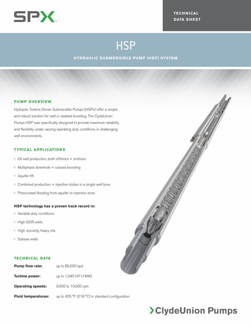
TECHNICAL DATA SHEET PUMP OVERVIEW Hydraulic Turbine Driven Submersible Pumps (HSPs) offer a simple and robust solution for well or seabed boosting. The ClydeUnion Pumps HSP was specifically designed to provide maximum reliability and flexibility under varying operating duty conditions in challenging well environments. TYPICAL APPLICATIONS • Oil well production, both offshore + onshore • Multiphase downhole + subsea boosting • Aquifer lift • Combined production + injection duties in a single well bore • Pressurized flooding from aquifer to injection zone HSP technology has a proven track record in: • Variable duty conditions • High GOR wells • High viscosity, heavy oils • Subsea wells HSP HYDRAULIC SUBMERSIBLE PUMP (HSP) SYSTEM TECHNICAL DATA Pump flow rate: up to 85,000 bpd Turbine power: up to 1,340 HP (1MW) Operating speeds: 3,000 to 10,000 rpm Fluid temperatures: up to 425 °F (218 °C) in standard configuration
Transcript of HSP - Global Industrial Equipment & Global … DATA SHEET PUMP OVERVIEW Hydraulic Turbine Driven...
TECH N ICAL
DATA S H E ET
PUMP OVERVIEW
Hydraulic Turbine Driven Submersible Pumps (HSPs) offer a simple
and robust solution for well or seabed boosting. The ClydeUnion
Pumps HSP was specifically designed to provide maximum reliability
and flexibility under varying operating duty conditions in challenging
well environments.
TYPICAL APPLICATIONS
• Oil well production, both offshore + onshore
• Multiphase downhole + subsea boosting
• Aquifer lift
• Combined production + injection duties in a single well bore
• Pressurized flooding from aquifer to injection zone
HSP technology has a proven track record in:
• Variable duty conditions
• High GOR wells
• High viscosity, heavy oils
• Subsea wells
HSPHYDRAULIC SUBMERSIBLE PUMP (HSP) SYSTEM
TECHNICAL DATA
Pump flow rate: up to 85,000 bpd
Turbine power: up to 1,340 HP (1MW)
Operating speeds: 3,000 to 10,000 rpm
Fluid temperatures: up to 425 °F (218 °C) in standard configuration
For more information about our worldwide locations, approvals, certifications, and local representatives, please visit www.spx.com.
SPX Corporation reserves the right to incorporate our latest design and material changes without notice or obligation. Design features, materials of construction and dimensional data,
as described in this bulletin, are provided for your information only and should not be relied upon unless confirmed in writing.
COPYRIGHT © 2012 SPX Corporation
P: +44 (0)141 637 7141 F: +44 (0)141 633 2399 E: [email protected]
FEATURES + BENEFITS
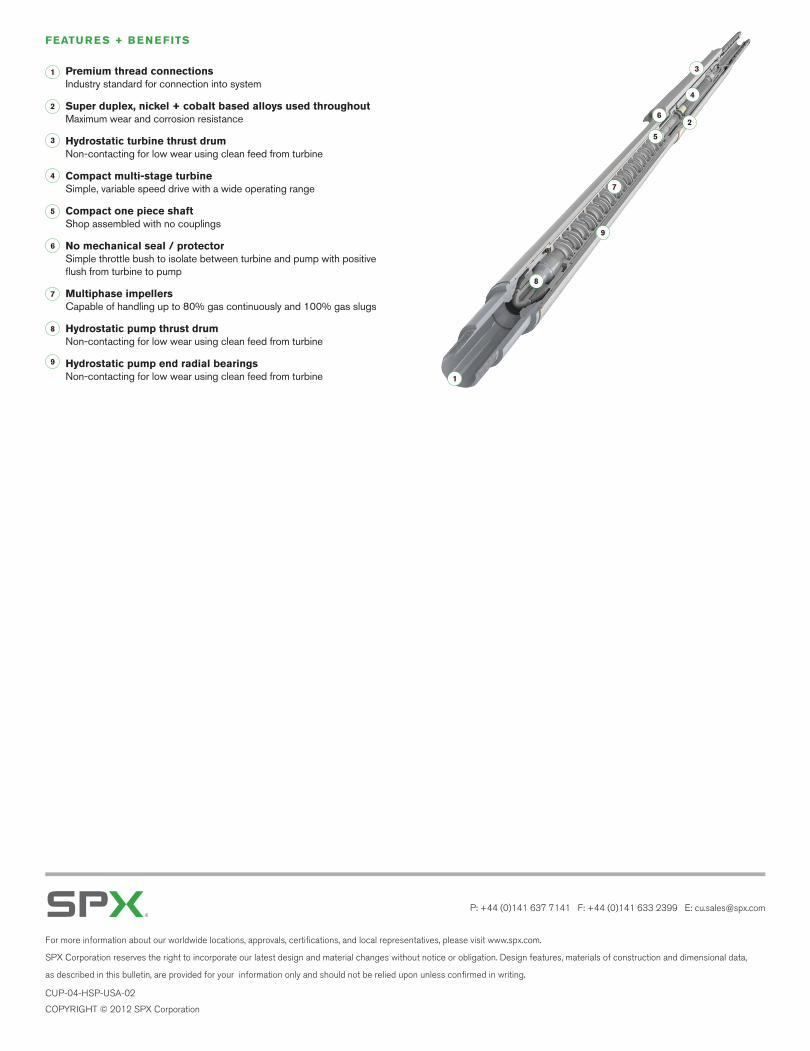
Premium thread connections Industry standard for connection into system
Super duplex, nickel + cobalt based alloys used throughout Maximum wear and corrosion resistance
Hydrostatic turbine thrust drum Non-contacting for low wear using clean feed from turbine
Compact multi-stage turbine Simple, variable speed drive with a wide operating range
Compact one piece shaft Shop assembled with no couplings
No mechanical seal / protector Simple throttle bush to isolate between turbine and pump with positive flush from turbine to pump
Multiphase impellers Capable of handling up to 80% gas continuously and 100% gas slugs
Hydrostatic pump thrust drum Non-contacting for low wear using clean feed from turbine
Hydrostatic pump end radial bearings Non-contacting for low wear using clean feed from turbine 1
2
3
4
5
6
8
7
5
4
3
2
1
6
7
8
9
9
CUP-04-HSP-USA-02
TECH N ICAL
DATA S H E ET
PUMP OVERVIEW
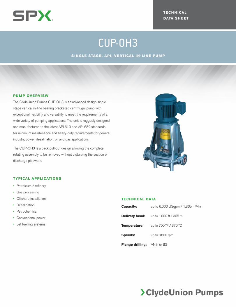
The ClydeUnion Pumps CUP-OH3 is an advanced design single
stage vertical in-line bearing bracketed centrifugal pump with
exceptional flexibility and versatility to meet the requirements of a
wide variety of pumping applications. The unit is ruggedly designed
and manufactured to the latest API 610 and API 682 standards
for minimum maintenance and heavy-duty requirements for general
industry, power, desalination, oil and gas applications.
The CUP-OH3 is a back pull-out design allowing the complete
rotating assembly to be removed without disturbing the suction or
discharge pipework.
TYPICAL APPLICATIONS
• Petroleum / refinery
• Gas processing
• Offshore installation
• Desalination
• Petrochemical
• Conventional power
• Jet fuelling systems
CUP-OH3S I NG LE STAG E, API , VE RTICAL I N-LI N E PU M P
TECHNICAL DATA
Capacity: up to 6,000 USgpm / 1,365 m³/hr
Delivery head: up to 1,000 ft / 305 m
Temperature: up to 700 °F / 370 °C
Speeds: up to 3,600 rpm
Flange drilling: ANSI or BS

For more information about our worldwide locations, approvals, certifications, and local representatives, please visit www.spx.com.
SPX Corporation reserves the right to incorporate our latest design and material changes without notice or obligation. Design features, materials of construction and dimensional data,
as described in this bulletin, are provided for your information only and should not be relied upon unless confirmed in writing.
COPYRIGHT © 2012 SPX Corporation
P: +44 (0)141 637 7141 F: +44 (0)141 633 2399 E: [email protected]
CUP-04-OH3-USA-02
TECH N ICAL
DATA S H E ET
PUMP OVERVIEW
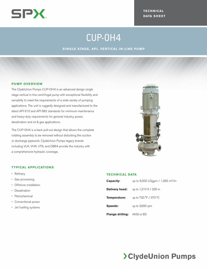
The ClydeUnion Pumps CUP-OH4 is an advanced design single
stage vertical in-line centrifugal pump with exceptional flexibility and
versatility to meet the requirements of a wide variety of pumping
applications. The unit is ruggedly designed and manufactured to the
latest API 610 and API 682 standards for minimum maintenance
and heavy-duty requirements for general industry, power,
desalination and oil & gas applications.
The CUP-OH4 is a back pull-out design that allows the complete
rotating assembly to be removed without disturbing the suction
or discharge pipework. ClydeUnion Pumps legacy brands
including VLK, VHK, VTK, and DB64 provide the industry with
a comprehensive hydraulic coverage.
TYPICAL APPLICATIONS
• Refinery
• Gas processing
• Offshore installation
• Desalination
• Petrochemical
• Conventional power
• Jet fuelling systems
CUP-OH4S I NG LE STAG E, API , VE RTICAL I N-LI N E PU M P
TECHNICAL DATA
Capacity: up to 6,000 USgpm / 1,365 m³/hr
Delivery head: up to 1,310 ft / 335 m
Temperature: up to 700 °F / 370 °C
Speeds: up to 3,600 rpm
Flange drilling: ANSI or BS

For more information about our worldwide locations, approvals, certifications, and local representatives, please visit www.spx.com.
SPX Corporation reserves the right to incorporate our latest design and material changes without notice or obligation. Design features, materials of construction and dimensional data,
as described in this bulletin, are provided for your information only and should not be relied upon unless confirmed in writing.
COPYRIGHT © 2012 SPX Corporation
P: +44 (0)141 637 7141 F: +44 (0)141 633 2399 E: [email protected]
CUP-04-OH4-USA-02
TECH N ICAL
DATA S H E ET
PUMP OVERVIEW
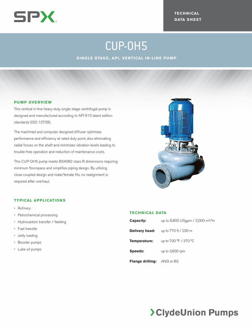
This vertical in-line heavy duty, single stage centrifugal pump is
designed and manufactured according to API 610 latest edition
standards (ISO 13709).
The machined and computer designed diffuser optimizes
performance and efficiency at rated duty point, also eliminating
radial forces on the shaft and minimizes vibration levels leading to
trouble-free operation and reduction of maintenance costs.
This CUP-OH5 pump meets BS4082 class R dimensions requiring
minimum floorspace and simplifies piping design. By utilizing
close coupled design and male/female fits, no realignment is
required after overhaul.
TYPICAL APPLICATIONS
• Refinery
• Petrochemical processing
• Hydrocarbon transfer / feeding
• Fuel transfer
• Jetty loading
• Booster pumps
• Lube oil pumps
CUP-OH5S I NG LE STAG E, API , VE RTICAL I N-LI N E PU M P
TECHNICAL DATA
Capacity: up to 8,800 USgpm / 2,000 m³/hr
Delivery head: up to 770 ft / 230 m
Temperature: up to 700 °F / 370 °C
Speeds: up to 3,600 rpm
Flange drilling: ANSI or BS

For more information about our worldwide locations, approvals, certifications, and local representatives, please visit www.spx.com.
SPX Corporation reserves the right to incorporate our latest design and material changes without notice or obligation. Design features, materials of construction and dimensional data,
as described in this bulletin, are provided for your information only and should not be relied upon unless confirmed in writing.
COPYRIGHT © 2012 SPX Corporation
P: +44 (0)141 637 7141 F: +44 (0)141 633 2399 E: [email protected]
CUP-04-OH5-USA-02
TECH N ICAL
DATA S H E ET
PUMP OVERVIEW
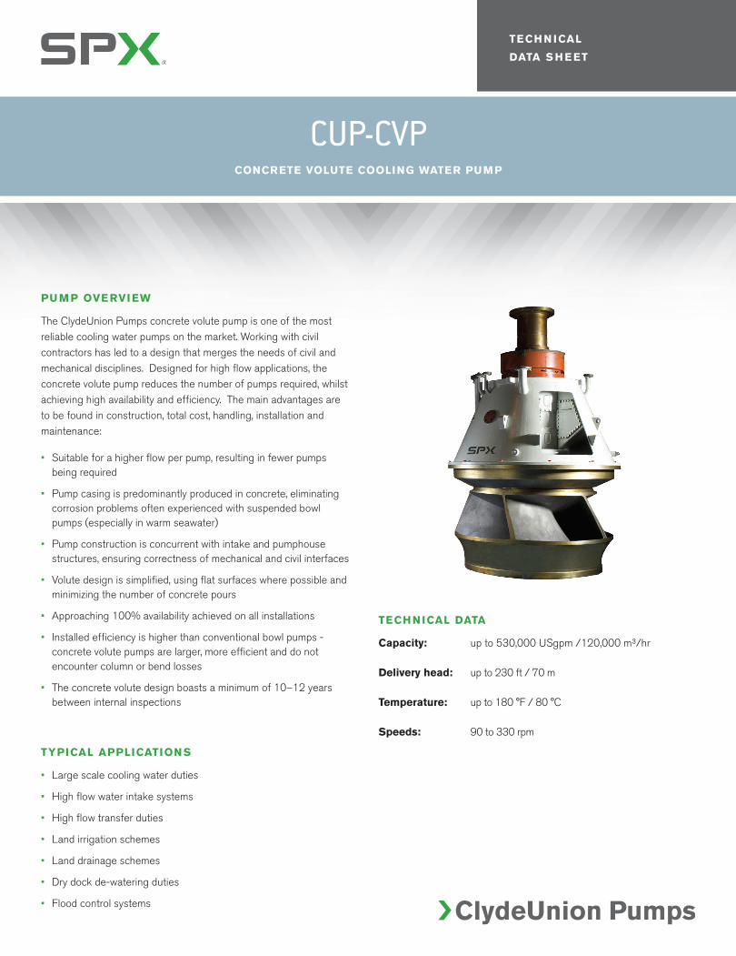
The ClydeUnion Pumps concrete volute pump is one of the most reliable cooling water pumps on the market. Working with civil contractors has led to a design that merges the needs of civil and mechanical disciplines. Designed for high flow applications, the concrete volute pump reduces the number of pumps required, whilst achieving high availability and efficiency. The main advantages are to be found in construction, total cost, handling, installation and maintenance:
• Suitable for a higher flow per pump, resulting in fewer pumps being required
• Pump casing is predominantly produced in concrete, eliminating corrosion problems often experienced with suspended bowl pumps (especially in warm seawater)
• Pump construction is concurrent with intake and pumphouse structures, ensuring correctness of mechanical and civil interfaces
• Volute design is simplified, using flat surfaces where possible and minimizing the number of concrete pours
• Approaching 100% availability achieved on all installations
• Installed efficiency is higher than conventional bowl pumps - concrete volute pumps are larger, more efficient and do not encounter column or bend losses
• The concrete volute design boasts a minimum of 10–12 years between internal inspections
TYPICAL APPLICATIONS
• Large scale cooling water duties
• High flow water intake systems
• High flow transfer duties
• Land irrigation schemes
• Land drainage schemes
• Dry dock de-watering duties
• Flood control systems
CUP-CVPCONCRETE VOLUTE COOLING WATER PUMP
TECHNICAL DATA
Capacity: up to 530,000 USgpm /120,000 m³/hr
Delivery head: up to 230 ft / 70 m
Temperature: up to 180 °F / 80 °C
Speeds: 90 to 330 rpm
For more information about our worldwide locations, approvals, certifications, and local representatives, please visit www.spx.com.
SPX Corporation reserves the right to incorporate our latest design and material changes without notice or obligation. Design features, materials of construction and dimensional data,
as described in this bulletin, are provided for your information only and should not be relied upon unless confirmed in writing.
COPYRIGHT © 2012 SPX Corporation
P: +44 (0)141 637 7141 F: +44 (0)141 633 2399 E: [email protected]
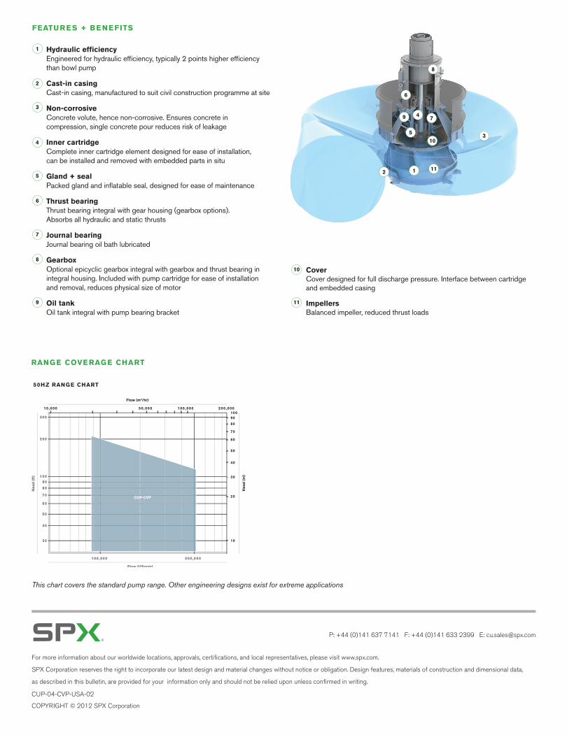
FEATURES + BENEFITS
Hydraulic efficiency Engineered for hydraulic efficiency, typically 2 points higher efficiency than bowl pump
Cast-in casing Cast-in casing, manufactured to suit civil construction programme at site
Non-corrosive Concrete volute, hence non-corrosive. Ensures concrete in compression, single concrete pour reduces risk of leakage
Inner cartridge Complete inner cartridge element designed for ease of installation, can be installed and removed with embedded parts in situ
Gland + seal Packed gland and inflatable seal, designed for ease of maintenance
Thrust bearing Thrust bearing integral with gear housing (gearbox options). Absorbs all hydraulic and static thrusts
Journal bearing Journal bearing oil bath lubricated
Gearbox Optional epicyclic gearbox integral with gearbox and thrust bearing in integral housing. Included with pump cartridge for ease of installation and removal, reduces physical size of motor
Oil tank Oil tank integral with pump bearing bracket
Cover Cover designed for full discharge pressure. Interface between cartridge and embedded casing
Impellers Balanced impeller, reduced thrust loads
12
3
4
5
6
9
8
7
5
4
3
2
1
6
7
10
10
8
9 11
11
CUP-04-CVP-USA-02
RANGE COVERAGE CHART
CUP-CVP
CUP-CVP
30
Head
(ft
)
Flow (USgpm)
Flow (m3/hr)
Head
(m
)
70
80
90 100
40
50
60
20
10
50,000 100,00010,000 200,000
100,000 500,000
200
30
300
40
50
60
70
80
90
100
This chart covers the standard pump range. Other engineering designs exist for extreme applications
50HZ RANGE CHART
TECH N ICAL
DATA S H E ET
PUMP OVERVIEW
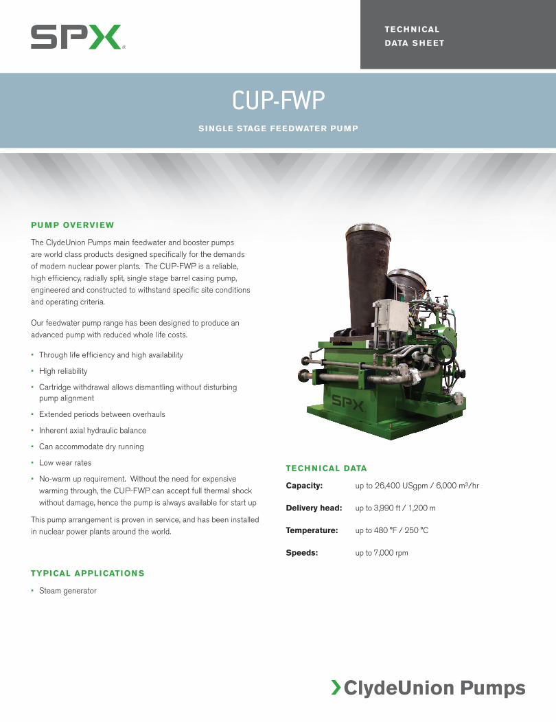
The ClydeUnion Pumps main feedwater and booster pumps are world class products designed specifically for the demands of modern nuclear power plants. The CUP-FWP is a reliable, high efficiency, radially split, single stage barrel casing pump, engineered and constructed to withstand specific site conditions and operating criteria.
Our feedwater pump range has been designed to produce an advanced pump with reduced whole life costs.
• Through life efficiency and high availability
• High reliability
• Cartridge withdrawal allows dismantling without disturbing pump alignment
• Extended periods between overhauls
• Inherent axial hydraulic balance
• Can accommodate dry running
• Low wear rates
• No-warm up requirement. Without the need for expensive warming through, the CUP-FWP can accept full thermal shock without damage, hence the pump is always available for start up
This pump arrangement is proven in service, and has been installed in nuclear power plants around the world.
TYPICAL APPLICATIONS
• Steam generator
CUP-FWPSINGLE STAGE FEEDWATER PUMP
TECHNICAL DATA
Capacity: up to 26,400 USgpm / 6,000 m³/hr
Delivery head: up to 3,990 ft / 1,200 m
Temperature: up to 480 °F / 250 °C
Speeds: up to 7,000 rpm
For more information about our worldwide locations, approvals, certifications, and local representatives, please visit www.spx.com.
SPX Corporation reserves the right to incorporate our latest design and material changes without notice or obligation. Design features, materials of construction and dimensional data,
as described in this bulletin, are provided for your information only and should not be relied upon unless confirmed in writing.
COPYRIGHT © 2012 SPX Corporation
P: +44 (0)141 637 7141 F: +44 (0)141 633 2399 E: [email protected]
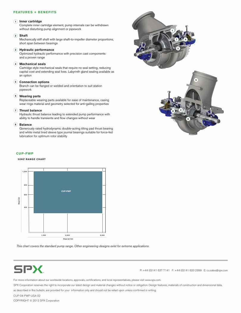
FEATURES + BENEFITS
Inner cartridge Complete inner cartridge element, pump internals can be withdrawn without disturbing pump alignment or pipework
Shaft Mechanically stiff shaft with large shaft-to-impeller diameter proportions, short span between bearings
Hydraulic performance Optimized hydraulic performance with precision cast components and a proven range
Mechanical seals Cartridge style mechanical seals that require no seal setting, reducing capital cost and extending seal lives. Labyrinth gland sealing available as an option
Connection options Branch can be flanged or welded and orientation to suit station pipework
Wearing parts Replaceable wearing parts available for ease of maintenance, casing wear rings material and geometry selected for anti-galling properties
Thrust balance Hydraulic thrust balance leading to extended pump performance with ability to handle transients and flow changes without wear
Balance Generously rated hydrodynamic double-acting tilting pad thrust bearing and white metal lined sleeve type journal bearings suitable for force-fed lubrication for optimum rotor stability
2
5
6
8
1
3
47
5
4
3
2
1
6
7
8
CUP-04-FWP-USA-02
This chart covers the standard pump range. Other engineering designs exist for extreme applications
50HZ RANGE CHART
Head
(m
)
1 ,200
Flow (m3/hr)
6,0001,000
800
600
400
2,000
CUP-FWP
CUP-FWP