HSM SERIES - RF Synthesizers - Holzworth … · HSM SERIES RF Synthesizer Modules HOLZWORTH...
16
HSM SERIES RF Synthesizer Modules HOLZWORTH INSTRUMENTATION, INC. HSM Series Jan 2014 BOULDER, COLORADO www.HOLZWORTH.com Email: [email protected] All rights reserved. Page 1 of 16 ULTRA LOW PHASE NOISE HSM DESIGN HIGHLIGHTS • Amplitude Accuracy ±0.25dB to as low as -70dBm • Frequency Switching Speed: 6µS, 100% settled • Pulse Modulation Burst Mode (internal pulse) • Onboard Precision 100MHz OCXO • 100MHz Reference Out: -165dBc/Hz 1/2 (10kHz OS) • Reference Input: 10MHz or 100MHz • SPI or USB Communications Interface • Internal Temperature Monitor Output The Holzworth HSM Series RF Synthesizer Modules are stand alone, CW sources. These sources are designed as building blocks for systems integration where performance at the foundation is critical. Holzworth synthesizers provide best in industry stability. When integrated as multiple units, the result is true phase coherency with industry leading channel-to-channel stability. Compare the HSM Series to competitive designs and discover the most compact form factor available in its overall performance class. The core architecture of the HSM Series modules is derived from Holzworth’s proprietary NON-PLL design to provide the ultimate in phase / frequency stability. This direct-digital/direct-analog hybrid design was originally developed as a key building block for our phase noise analysis products. The hybrid architecture provides frequency agility & resolution, phase continuous switching and predictable performance without compromising on spurious or phase noise performance. HSM EXTENDED FREQUENCY OPTIONS: Model No. Frequency Range Phase Noise Performance HSM1001A 250kHz to 1GHz -133dBc/Hz at 1GHz (10kHz offset) HSM2001A 250kHz to 2GHz -127dBc/Hz at 2GHz (10kHz offset) HSM3001A 250kHz to 3GHz -123dBc/Hz at 3GHz (10kHz offset) HSM4001A 250kHz to 4GHz -121dBc/Hz at 4GHz (10kHz offset) HSM6001A 250kHz to 6.7GHz -117dBc/Hz at 6GHz (10kHz offset) Note: Holzworth’s “Ultra Low Phase Noise” statement is real. We make no assumptions. 100% of all RF synthesizers manufactured by Holzworth Instrumentation are subjected to full phase noise evaluation. This critical parameter cannot be accepted as being “OK” based on spectrum analysis or an alternate test. The versatile HSM Synthesizer Modules can be controlled directly via the SPI bus, the Holzworth GUI, a preloaded lookup table, LabVIEW TM , MATLAB TM , C++, C#, etc. Some systems integrators have preferred the supported Linux platform over a Windows based PC. An advanced application example uses a preloaded lookup table in a multi-channel configuration further leveraging the unique NON-PLL characteristics to achieve switching speeds of <100ns with phase memory. The attractive performance-to-price ratios available with the Holzworth HSM Series offer optimal solutions for electronics design, manufacturing test applications, and OEM systems integration. Finally, with MTBFs greater than 200,000 hours, the HSM Series synthesizer modules have been designed to exceed the most stringent reliability requirements. PRODUCT SUMMARY
Transcript of HSM SERIES - RF Synthesizers - Holzworth … · HSM SERIES RF Synthesizer Modules HOLZWORTH...

HSM SERIES
RF Synthesizer Modules
HOLZWORTH INSTRUMENTATION, INC. HSM Series Jan 2014
BOULDER, COLORADO www.HOLZWORTH.com
Email: [email protected] All rights reserved. Page 1 of 16
ULTRA LOW PHASE NOISE
HSM DESIGN HIGHLIGHTS
• Amplitude Accuracy ±0.25dB to as low as -70dBm
• Frequency Switching Speed: 6µS, 100% settled
• Pulse Modulation Burst Mode (internal pulse)
• Onboard Precision 100MHz OCXO
• 100MHz Reference Out: -165dBc/Hz1/2
(10kHz OS)
• Reference Input: 10MHz or 100MHz
• SPI or USB Communications Interface
• Internal Temperature Monitor Output
Holz The Holzworth HSM Series RF Synthesizer Modules are stand alone, CW sources. These sources are designed as building blocks for systems integration where performance at the foundation is critical. Holzworth synthesizers provide best in industry stability. When integrated as multiple units, the result is true phase coherency with industry leading channel-to-channel stability. Compare the HSM Series to competitive designs and discover the most compact form factor available in its overall performance class. The core architecture of the HSM Series modules is derived from Holzworth’s proprietary NON-PLL design to provide the ultimate in phase / frequency stability. This direct-digital/direct-analog hybrid design was originally developed as a key building block for our phase noise analysis products. The hybrid architecture provides frequency agility & resolution, phase continuous switching and predictable performance without compromising on spurious or phase noise performance.
HSM EXTENDED FREQUENCY OPTIONS:
Model No. Frequency Range Phase Noise Performance
HSM1001A 250kHz to 1GHz -133dBc/Hz at 1GHz (10kHz offset) HSM2001A 250kHz to 2GHz -127dBc/Hz at 2GHz (10kHz offset) HSM3001A 250kHz to 3GHz -123dBc/Hz at 3GHz (10kHz offset) HSM4001A 250kHz to 4GHz -121dBc/Hz at 4GHz (10kHz offset) HSM6001A 250kHz to 6.7GHz -117dBc/Hz at 6GHz (10kHz offset)
Note: Holzworth’s “Ultra Low Phase Noise” statement is real. We make no assumptions. 100% of all RF
synthesizers manufactured by Holzworth Instrumentation are subjected to full phase noise evaluation. This critical parameter cannot be accepted as being “OK” based on spectrum analysis or an alternate test.
The versatile HSM Synthesizer Modules can be controlled directly via the SPI bus, the Holzworth GUI, a preloaded lookup table, LabVIEWTM, MATLABTM, C++, C#, etc. Some systems integrators have preferred the supported Linux platform over a Windows based PC. An advanced application example uses a preloaded lookup table in a multi-channel configuration further leveraging the unique NON-PLL characteristics to achieve switching speeds of <100ns with phase memory. The attractive performance-to-price ratios available with the Holzworth HSM Series offer optimal solutions for electronics design, manufacturing test applications, and OEM systems integration. Finally, with MTBFs greater than 200,000 hours, the HSM Series synthesizer modules have been designed to exceed the most stringent reliability requirements.
PRODUCT SUMMARY
HSM SERIES
RF Synthesizer Modules
HOLZWORTH INSTRUMENTATION, INC. HSM Series Jan 2014
BOULDER, COLORADO www.HOLZWORTH.com
Email: [email protected] All rights reserved. Page 2 of 16
ULTRA LOW PHASE NOISE
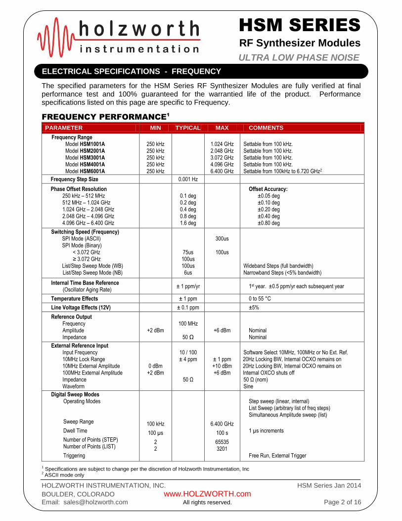
The specified parameters for the HSM Series RF Synthesizer Modules are fully verified at final performance test and 100% guaranteed for the warrantied life of the product. Performance specifications listed on this page are specific to Frequency.
FREQUENCY PERFORMANCE1
PARAMETER MIN TYPICAL MAX COMMENTS
Frequency Range Model HSM1001A Model HSM2001A Model HSM3001A Model HSM4001A Model HSM6001A
250 kHz 250 kHz 250 kHz 250 kHz 250 kHz
1.024 GHz 2.048 GHz 3.072 GHz 4.096 GHz 6.400 GHz
Settable from 100 kHz. Settable from 100 kHz. Settable from 100 kHz. Settable from 100 kHz. Settable from 100kHz to 6.720 GHz2
Frequency Step Size 0.001 Hz
Phase Offset Resolution 250 kHz – 512 MHz 512 MHz – 1.024 GHz 1.024 GHz – 2.048 GHz 2.048 GHz – 4.096 GHz 4.096 GHz – 6.400 GHz
0.1 deg 0.2 deg 0.4 deg 0.8 deg 1.6 deg
Offset Accuracy: ±0.05 deg ±0.10 deg ±0.20 deg ±0.40 deg ±0.80 deg
Switching Speed (Frequency) SPI Mode (ASCII) SPI Mode (Binary) < 3.072 GHz ≥ 3.072 GHz List/Step Sweep Mode (WB) List/Step Sweep Mode (NB) List/Step Sweep Mode (NB)
75us 100us 100us 6us
300us
100us
Wideband Steps (full bandwidth) Narrowband Steps (<5% bandwidth)
Internal Time Base Reference (Oscillator Aging Rate)
± 1 ppm/yr 1st year. ±0.5 ppm/yr each subsequent year
Temperature Effects ± 1 ppm 0 to 55 °C
Line Voltage Effects (12V) ± 0.1 ppm ±5%
Reference Output Frequency Amplitude Impedance
+2 dBm
100 MHz
50 Ω
+6 dBm
Nominal Nominal
External Reference Input Input Frequency 10MHz Lock Range 10MHz External Amplitude 100MHz External Amplitude Impedance Waveform
0 dBm +2 dBm
10 / 100 ± 4 ppm
50 Ω
± 1 ppm +10 dBm +6 dBm
Software Select 10MHz, 100MHz or No Ext. Ref. 20Hz Locking BW, Internal OCXO remains on 20Hz Locking BW, Internal OCXO remains on Internal OXCO shuts off 50 Ω (nom) Sine
Digital Sweep Modes
Operating Modes Sweep Range
Dwell Time
Number of Points (STEP) Number of Points (LIST)
Triggering
100 kHz
100 µs
2 2
6.400 GHz
100 s
65535 3201
Step sweep (linear, internal) List Sweep (arbitrary list of freq steps) Simultaneous Amplitude sweep (list)
1 µs increments
Free Run, External Trigger
1 Specifications are subject to change per the discretion of Holzworth Instrumentation, Inc
2 ASCII mode only
ELECTRICAL SPECIFICATIONS - FREQUENCY

HSM SERIES
RF Synthesizer Modules
HOLZWORTH INSTRUMENTATION, INC. HSM Series Jan 2014
BOULDER, COLORADO www.HOLZWORTH.com
Email: [email protected] All rights reserved. Page 3 of 16
ULTRA LOW PHASE NOISE
The specified parameters for the HSM Series RF Synthesizer Modules are fully verified at final performance test and 100% guaranteed for the warranted life of the product. Performance specifications listed on this page are specific to Amplitude.
AMPLITUDE PERFORMANCE1
PARAMETER MIN2
TYPICAL3
MAX2
COMMENTS
Output Power (Calibrated) -70 dBm +10 dBm Settable from -100 to +15 dBm
Resolution 0.01 dB
Connector 50 Ω SMA
SWR (S11) f < 32MHz 32MHz < f < 1.024GHz 1.024GHz < f < 6.720GHz
1.4 (-15.6 dB) 1.15 (-23.0 dB) 1.3 (-17.7 dB)
1.7 (-11.7 dB) 1.4 (-15.6 dB) 1.5 (-14 dB)
Maximum Reverse Power Max DC Voltage
> 100 kHz
25 VDC maximum by design. 10 mW (10dBm) max by design.
Switching Speed (Amplitude) SPI Mode List / Step Sweep Mode
300 µs 100 µs
Settling to within 0.1 dB.
Absolute Level Accuracy f < 10MHz 0 to -70dBm 10MHz < f < 32MHz 0 to -70dBm 32MHz < f < 4.096GHz +10 to -30dBm 32MHz < f < 4.096GHz -30 to -70dBm 4.096GHz < f < 6.4GHz +10 to -30dBm 4.096GHz < f < 6.4GHz -30 to -60dBm
+0.25/ -2.0 dB +0.1/ -1.25 dB
± 0.10 dB ± 0.25 dB ± 0.15 dB ± 0.25 dB
NS
+0.6/ -2.0 dB ± 0.5 dB ± 1.0 dB ± 0.6 dB ± 1.1 dB
SSB Phase Noise 100 MHz, 10kHz offset 500 MHz, 10kHz offset 1.0 GHz, 10kHz offset 2.0 GHz, 10kHz offset 3.0 GHz, 10kHz offset 4.0 GHz, 10kHz offset 6.0 GHz, 10kHz offset
≤ -153 dBc/Hz ≤ -139 dBc/Hz ≤ -133 dBc/Hz ≤ -127 dBc/Hz ≤ -123 dBc/Hz ≤ -121 dBc/Hz ≤ -117 dBc/Hz
≤ -145 dBc/Hz ≤ -134 dBc/Hz ≤ -128 dBc/Hz ≤ -122 dBc/Hz ≤ -117 dBc/Hz ≤ -115 dBc/Hz ≤ -111 dBc/Hz
≤ -152 dBc/Hz @ 20kHz offset ≤ -140 dBc/Hz @ 20kHz offset ≤ -134 dBc/Hz @ 20kHz offset ≤ -128 dBc/Hz @ 20kHz offset ≤ -124 dBc/Hz @ 20kHz offset ≤ -122 dBc/Hz @ 20kHz offset ≤ -118 dBc/Hz @ 20kHz offset
Harmonics (CW mode)
Pout = 0dBm Pout = +10dBm
-40 dBc -30 dBc
-30 dBc
NS
Non-Harmonics (CW mode)
250 kHz to 3.072 GHz 3.072 GHz to 6.400 GHz
-70 dBc -60 dBc
-60 dBc -50 dBc
@ 0 dBm @ 0 dBm
Sub-Harmonics (CW mode)
250 kHz to 3.072 GHz 3.072 GHz to 6.400 GHz
-70 dBc -60 dBc
-60 dBc -50dBc
@ 0 dBm @ 0 dBm
Jitter 155 MHz 622 MHz 2.488 GHz
60 fs 61 fs 55 fs
NS NS NS
100Hz < BW < 1.5MHz 1kHz < BW < 5MHz 5kHz < BW < 20MHz
1 Specifications are subject to change per the discretion of Holzworth Instrumentation, Inc.
2 All MIN/ MAX (Minimum/ Maximum) performance parameters are guaranteed and 100% verified during final performance test.
3 Typical performance is “by design” and consistent with field performance data.
ELECTRICAL SPECIFICATIONS - AMPLITUDE
*** Some applications may require reverse power protection.
25C to 35C (case temperature)

HSM SERIES
RF Synthesizer Modules
HOLZWORTH INSTRUMENTATION, INC. HSM Series Jan 2014
BOULDER, COLORADO www.HOLZWORTH.com
Email: [email protected] All rights reserved. Page 4 of 16
ULTRA LOW PHASE NOISE
The modulation parameters listed here are based on modulation functions as related to the use of an external modulation stimulus. Internal “self pulse” functions are available with the current revision of the HSM series RF synthesizers (to be specified).
PARAMETER PERFORMANCE COMMENTS
FREQUENCY MODULATION1 (Analog)
Max Deviation 100 kHz
Resolution 0.01% or 1mHz, whichever is greater
Modulation Freq. Response DC to 20 kHz (-3dB) DC Coupled
Sensitivity when using Ext. Input ± 1V peak into 50Ω + 1V: Maximum Positive Deviation 0V: Zero Deviation from Carrier
- 1V: Maximum Negative Deviation
PHASE MODULATION1 (Analog)
Modulation Deviation ±1.6 deg to ±180 deg
Frequency Response DC to 20 kHz (-3dB) DC Coupled
Resolution Frequency Dependent See Phase Offset Specification
Sensitivity when using Ext. Input ± 1V peak into 50Ω + 1V: Maximum Positive Deviation 0V: Zero Deviation from Carrier
- 1V: Maximum Negative Deviation
AMPLITUDE MODULATION1 (Analog)
AM Depth Type Linear
Depth Maximum Resolution Depth Accuracy
5% to 75%
<3% of Maximum Depth 5% of Maximum Depth
0.45 dB to 12 dB
Modulation Rate DC to 10 kHz (-3dB) DC Coupled
Sensitivity when using Ext. Input ± 1V peak for indicated Depth (into 50Ω) + 1V: Maximum Amplitude 0V: 50% of Maximum Depth
- 1V: Maximum Depth
PULSE MODULATION1 (Analog)
Risetime (Tr) <100 ns
Falltime (Tf) <100 ns
On/Off Ratio > 70dB
Minimum Pulse Width 200 ns
ALC Loop Deviation (ALC disabled) 1dB difference from ALC enabled 1 Specifications are subject to change per the discretion of Holzworth Instrumentation, Inc
PARAMETER PERFORMANCE COMMENTS
External Trigger Threshold +1.2V ±5% into 50Ω
ELECTRICAL SPECIFICATIONS - MODULATION (External Stimulus)

HSM SERIES
RF Synthesizer Modules
HOLZWORTH INSTRUMENTATION, INC. HSM Series Jan 2014
BOULDER, COLORADO www.HOLZWORTH.com
Email: [email protected] All rights reserved. Page 5 of 16
ULTRA LOW PHASE NOISE
HSM series synthesizers that have the firmware version 3.31 or higher, are capable of operating in self pulse modulation mode, which does not require an external stimulus signal.
PARAMETER PERFORMANCE COMMENTS
PULSE MODULATION1 (Analog)
Risetime (Tr) fc < 512MHz fc > 512 MHz
11ns (typical)
NOT SPECIFIED
Falltime (Tf) <100 ns
On/Off Ratio > 70dB
Minimum Pulse Width 1 us
ALC Loop Deviation (ALC disabled) 1dB difference from ALC enabled 1 Specifications are subject to change per the discretion of Holzworth Instrumentation, Inc
(Figure 1: Self Pulse Mod fc = 500MHz, 1us Pulse
2)
2 Internal pulse modulation for frequencies greater than 512MHz will exhibit increased settling time.
Contact Holzworth customer support for additional data.
ELECTRICAL SPECIFICATIONS - SELF PULSE MODULATION

HSM SERIES
RF Synthesizer Modules
HOLZWORTH INSTRUMENTATION, INC. HSM Series Jan 2014
BOULDER, COLORADO www.HOLZWORTH.com
Email: [email protected] All rights reserved. Page 6 of 16
ULTRA LOW PHASE NOISE
Pulse modulation will exhibit longer rise/fall times for frequencies greater than 512 MHz. Figures 2 and 3 below demonstrate this difference between set frequencies.
Figure 2a: Pulse Mod Rise Time, fc = 500MHz Figure 2b: Pulse Mod Rise Time, fc = 530MHz
Figure 3a: Pulse Mod Fall Time, fc = 500MHz Figure 3b: Pulse Mod Fall Time, fc = 530MHz
ELECTRICAL SPECIFICATIONS - SELF PULSE MODULATION (continued)
HSM SERIES
RF Synthesizer Modules
HOLZWORTH INSTRUMENTATION, INC. HSM Series Jan 2014
BOULDER, COLORADO www.HOLZWORTH.com
Email: [email protected] All rights reserved. Page 7 of 16
ULTRA LOW PHASE NOISE
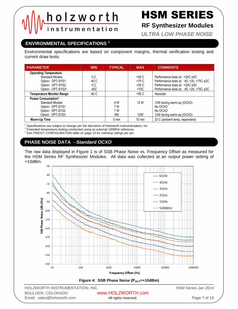
Environmental specifications are based on component margins, thermal verification testing and current draw tests.
PARAMETER MIN TYPICAL MAX COMMENTS
Operating Temperature Standard Models Option: OPT-SYS1 Option: OPT-SYS2 Option: OPT-SYS32
0 C
-40 C 0 C
-40C
+55 C +75 C +55 C +75C
Performance tests at: +20C ±5C Performance tests at: -40, +20, +75C ±2C Performance tests at: +20C ±5C Performance tests at: -40, +20, +75C ±2C
Temperature Monitor Range -40 C +85 C Absolute
Power Consumption3
Standard Models Option: OPT-SYS1 Option: OPT-SYS2 Option: OPT-SYS3
9 W 7 W 7 W 9W
12 W
12W
12W during warm-up (OCXO) No OCXO No OCXO 12W during warm-up (OCXO)
Warm-Up Time 5 min 10 min 20 C (ambient temp. dependent) 1 Specifications are subject to change per the discretion of Holzworth Instrumentation, Inc
2 Extended temperature testing conducted using an external 100MHz reference.
3 See PINOUT CONFIGURATION table on page 10 for volt/amp ratings per pin.
The raw data displayed in Figure 1 is of SSB Phase Noise vs. Frequency Offset as measured for the HSM Series RF Synthesizer Modules. All data was collected at an output power setting of +10dBm.
Figure 4: SSB Phase Noise (POUT=+10dBm)
PHASE NOISE DATA - Standard OCXO
ENVIRONMENTAL SPECIFICATIONS 1

HSM SERIES
RF Synthesizer Modules
HOLZWORTH INSTRUMENTATION, INC. HSM Series Jan 2014
BOULDER, COLORADO www.HOLZWORTH.com
Email: [email protected] All rights reserved. Page 8 of 16
ULTRA LOW PHASE NOISE
The HSM Series RF Synthesizer Modules can be equipped with an optional, high performance OCXO. Option OPT-OCXO provides an approximate 10dB improvement in the phase noise at close to the carrier (10Hz offset). The example plots contained in this section show the phase noise improvement with OPT-OCXO versus that with a standard OCXO installed.
Figure 5: SSB Phase Noise OPT-OCXO Comparison (POUT=+10dBm)
PHASE NOISE DATA - Optional OCXO

HSM SERIES
RF Synthesizer Modules
HOLZWORTH INSTRUMENTATION, INC. HSM Series Jan 2014
BOULDER, COLORADO www.HOLZWORTH.com
Email: [email protected] All rights reserved. Page 9 of 16
ULTRA LOW PHASE NOISE
The data contained in this section demonstrates the spectral purity performance of the HSM Series designs. Spectrum analyzer test settings: 300kHz Resolution BW, 30kHz Video BW.
Figure 6a: 500MHz Narrow Band Spectrum
Figure 6b: 500MHz Broad Band Spectrum
Figure 7a: 1GHz Narrow Band Spectrum
Figure 7b: 1GHz Broad Band Spectrum
Figure 8a: 2GHz Narrow Band Spectrum Figure 8b: 2GHz Broad Band Spectrum
SPECTRAL PURITY DATA

HSM SERIES
RF Synthesizer Modules
HOLZWORTH INSTRUMENTATION, INC. HSM Series Jan 2014
BOULDER, COLORADO www.HOLZWORTH.com
Email: [email protected] All rights reserved. Page 10 of 16
ULTRA LOW PHASE NOISE
Figure 9a: 3GHz Narrow Band Spectrum
Figure 9b: 3GHz Broad Band Spectrum
Figure 10a: 4GHz Narrow Band Spectrum
Figure 10b: 4GHz Broad Band Spectrum
Figure 11a: 6.4GHz Narrow Band Spectrum Figure 11b: 6.4GHz Broad Band Spectrum
Data at additional frequencies available upon request.
HSM SERIES
RF Synthesizer Modules
HOLZWORTH INSTRUMENTATION, INC. HSM Series Jan 2014
BOULDER, COLORADO www.HOLZWORTH.com
Email: [email protected] All rights reserved. Page 11 of 16
ULTRA LOW PHASE NOISE
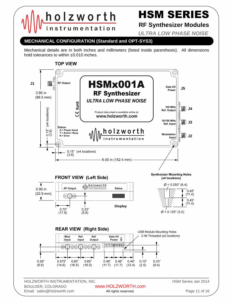
Mechanical details are in both inches and millimeters (listed inside parenthesis). All dimensions hold tolerances to within ±0.010 inches.
MECHANICAL CONFIGURATION (Standard and OPT-SYS3)
J1
J2
J3
J4
J5
Display

HSM SERIES
RF Synthesizer Modules
HOLZWORTH INSTRUMENTATION, INC. HSM Series Jan 2014
BOULDER, COLORADO www.HOLZWORTH.com
Email: [email protected] All rights reserved. Page 12 of 16
ULTRA LOW PHASE NOISE
Option “OPT-SYS1” & “OPT-SYS2” do not contain an OCXO, allowing for an extended operating temperature range and smaller form factor. An external 100MHz reference is required. OPT-SYS1 units are performance tested over full specified temperature range. Mechanical details are in both inches and millimeters (listed inside parenthesis). All dimensional tolerances are within ±0.010in.
MECHANICAL CONFIGURATION - OPTIONS: OPT-SYS1 / OPT-SYS2
J1
J2
J3
J4
J5
Display

HSM SERIES
RF Synthesizer Modules
HOLZWORTH INSTRUMENTATION, INC. HSM Series Jan 2014
BOULDER, COLORADO www.HOLZWORTH.com
Email: [email protected] All rights reserved. Page 13 of 16
ULTRA LOW PHASE NOISE
The interfaces defined within this section are cross referenced to the mechanical configuration included in this document. Ports are labeled on the synthesizer modules, but numbers are not physically printed on the module.
J-PORT DEFINITIONS
PORT LABEL DESCRIPTION
J1 RF Output SMA Jack, Multiplexed, 50ohm Input
Max Reverse Power: 10dBm (10mW)
J2 Modulation Input
SMA Jack, Multiplexed, 50ohm Input
Frequency Modulation: ± 1 V Analog Input
Amplitude Modulation: 0 to 1 V Analog Input
Phase Modulation: ± 1 V Analog Input
Trigger/Pulse mod: 1.2 V Threshold
Max Voltage: 5VDC
J3 10/100 MHz Ref. Input
SMA Jack: 10MHz/100MHz Reference Input (software selectable)
10MHz: 0dBm to +10dBm Input (PLL Lock Range: ±1ppm)
100MHz: +4 dBm out, ± 2 dB Input (Internal OCXO is shut off)
Maximum Input: 15dBm (32mW)
J4 100MHz Ref. Output
SMA Jack: 100MHz Reference Output
100MHz: +4 dBm out, ± 2 dB (nom)
Max Reverse Power: 15dBm (32mW)
J5 Data I/O - Power 2mm, 20pin (2x10) Milli-grid Shrouded Pin Header (detent type) Contains Power, Ground, SPI and Status Indicators
Display Status Tri-color LED Indicator Panel: GREEN = Power Good YELLOW = Communication Active / Busy / Not Ready RED = ERROR (i.e. no 10MHz PLL lock, Unleveled, etc.)
PINOUT CONFIGURATION
PIN No. Label PIN No. Label
1 GND 2 GND
3 + 5V, 1A (max) 4 +5V tied to pin 3
5 +12V , 400mA (nom), 600mA (warm-up)1 6 N.C. (reserved)
7 NC 8 N.C. (reserved)
9 INPUT: /RESET (10k PU to 3.3V) 10 N.C. (reserved)
11 INPUT: /CS (Synthesizer Select) 12 N.C. (reserved)
13 OUTPUT: SDO (Synthesizer Data Output) 14 OUTPUT: Power Good (OC – 47k PU to 3.3V)
15 INPUT: SDI (Synthesizer Data Input) 16 OUTPUT: /ERROR (OC – 47k PU to 3.3V)
17 INPUT: SCLK (Synthesizer Clock Input) 18 OUTPUT: /BUSY (OC – 47k PU to 3.3V)
19 GND 20 GND
INTERFACE DEFINITIONS
HSM SERIES
RF Synthesizer Modules
HOLZWORTH INSTRUMENTATION, INC. HSM Series Jan 2014
BOULDER, COLORADO www.HOLZWORTH.com
Email: [email protected] All rights reserved. Page 14 of 16
ULTRA LOW PHASE NOISE
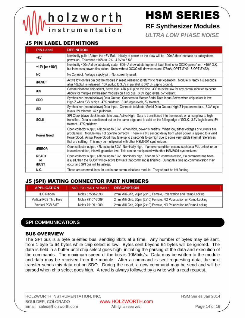
J5 PIN LABEL DEFINITIONS
PIN Label DEFINITION
+5V Nominally pulls 1A from the +5V Rail. Initially at power on the draw will be 100mA then increase as subsystems power-on. Tolerance +10% to -2%. 4.9V to 5.5V.
+12V [or +15V] Nominally 400mA draw at steady state. 600mA draw at startup for at least 5 mins for OCXO power\ on. +15V O.K.. but increases power dissipation. Units without OCXO will draw constant 175mA (OPTT-SYS1 & OPT-SYS2).
NC No Connect. Voltage supply pin. Not currently used.
/RESET Active low on this pin put the module in reset, releasing it returns to reset operation. Module is ready 1-2 seconds after /RESET is released. 10K pullup to 3.3V in parallel to 0.01uF cap to ground.
/CS Communications chip select, active low. 47K pullup on this line. /CS must be low for any communication to occur. Allows for multiple synthesizer modules on 1 spi bus. 3.3V logic levels, 5V tolerant.
SDO Synthesizer (module/slave) Data Output. Connects to Master Serial Data Input (Active when chip select is low. High-Z when /CS is high. 47K pulldown. 3.3V logic levels, 5V tolerant.
SDI Synthesizer (module/slave) Data Input. Connects to Master Serial Data Output (High-Z input on module. 3.3V logic levels, 5V tolerant. 47K pulldown.
SCLK SPI Clock (slave clock input). Idle Low, Active High. Data is transitioned into the module on a rising low to high transition. Data is transitioned out on the same edge and is valid on the falling edge of SCLK. 3.3V logic levels, 5V tolerant. 47K pulldown.
Power Good
Open collector output, 47k pullup to 3.3V. When high, power is healthy. When low, either voltages or currents are problematic. Module may not operate correctly. There is a 0.5 second delay from when power is applied to a valid PowerGood. Actual PowerGood may take up to 2 seconds to go high due to some very stable internal references that are settling. This may be multiplexed with other HSM6001 synthesizers.
/ERROR Open collector output, 47k pullup to 3.3V. Nominally high. If an error condition occurs, such as a PLL unlock or un-leveled condition, this will go active low. This can be multiplexed with other HSM6001 synthesizers.
READY or /BUSY
Open collector output, 47k pullup to 3.3V. Nominally high. After an SPI communication, if a command has been issued, then the /BUSY will go active low until that command is finished. During this time no communication may occur and SPI bus will be asleep.
N.C. These are reserved lines for use in our communications module. They should be left floating.
J5 (SPI) MATING CONNECTOR PART NUMBERS
APPLICATION MOLEX PART NUMER DESCRIPTION
IDC Ribbon Molex 87568-2093 2mm Milli-Grid, 20pin (2x10) Female, Polarization and Ramp Locking
Vertical PCB Thru Hole Molex 79107-7009 2mm Milli-Grid, 20pin (2x10) Female, NO Polarization or Ramp Locking
Vertical PCB SMT Molex 79109-1009 2mm Milli-Grid, 20pin (2x10) Female, NO Polarization or Ramp Locking
BUS OVERVIEW
The SPI bus is a byte oriented bus, sending 8bits at a time. Any number of bytes may be sent, from 1 byte to 64 bytes while chip select is low. Bytes sent beyond 64 bytes will be ignored. The data is held in a buffer until chip select goes high, initiating the parsing of the data and execution of the commands. The maximum speed of the bus is 10Mbits/s. Data may be written to the module and data may be received from the module. After a command is sent requesting data, the next transfer sends this data out on SDO. During the read, a new command may be send and will be parsed when chip select goes high. A read is always followed by a write with a read request.
SPI COMMUNICATIONS
HSM SERIES
RF Synthesizer Modules
HOLZWORTH INSTRUMENTATION, INC. HSM Series Jan 2014
BOULDER, COLORADO www.HOLZWORTH.com
Email: [email protected] All rights reserved. Page 15 of 16
ULTRA LOW PHASE NOISE
BUS HARDWARE PROTOCOL
Data is clocked into the module on the rising edge of sclk. Data is clocked out of the module on this same edge. Data output is valid on the falling edge of sclk. Data is only transferred when chip select is low. When chip select goes high, this initiates the parsing and execution of data.
CONTROLLING MULTIPLE SYNTHESIZERS
The SPI bus may be daisy chained. The Status flags can be daisy chained as well, they are open-collector. Each synthesizer requires it's own chip select in a multiple channel scenario.
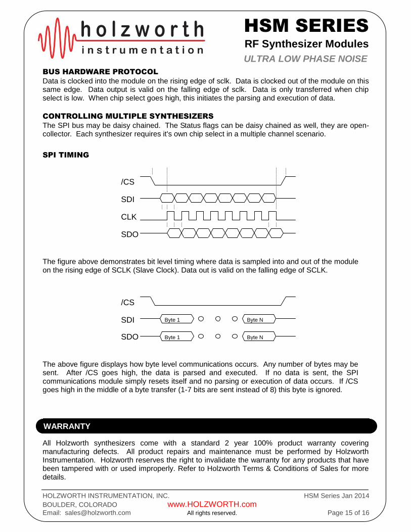
SPI TIMING
The figure above demonstrates bit level timing where data is sampled into and out of the module on the rising edge of SCLK (Slave Clock). Data out is valid on the falling edge of SCLK.
The above figure displays how byte level communications occurs. Any number of bytes may be sent. After /CS goes high, the data is parsed and executed. If no data is sent, the SPI communications module simply resets itself and no parsing or execution of data occurs. If /CS goes high in the middle of a byte transfer (1-7 bits are sent instead of 8) this byte is ignored.
All Holzworth synthesizers come with a standard 2 year 100% product warranty covering manufacturing defects. All product repairs and maintenance must be performed by Holzworth Instrumentation. Holzworth reserves the right to invalidate the warranty for any products that have been tampered with or used improperly. Refer to Holzworth Terms & Conditions of Sales for more details.
/CS
SDI
CLK
SDO
/CS
SDI
SDO
Byte 1
Byte 1
Byte N
Byte N
WARRANTY
HSM SERIES
RF Synthesizer Modules
HOLZWORTH INSTRUMENTATION, INC. HSM Series Jan 2014
BOULDER, COLORADO www.HOLZWORTH.com
Email: [email protected] All rights reserved. Page 16 of 16
ULTRA LOW PHASE NOISE
Holzworth HSM series RF synthesizers have options to assist with better meeting specific systems requirements. OPT-OCXO 10dB Improved Close to the Carrier Phase Noise OPT-SYS1 14mm Profile (no OCXO), Tested over extended Temp. Range OPT-SYS2 14mm Profile (no OCXO), Tested over standard Temp. Range OPT-SYS3 Includes internal OCXO. Tested over extended Temp. Range with external 100MHz reference. Communications modules are also made available for ease of integration or simply to match legacy laboratory communications requirements. USB, Ethernet, etc. modules can be purchased directly from Holzworth. HCM1 USB Communications Module with power supply HCM3 Ethernet Communications Module with power supply
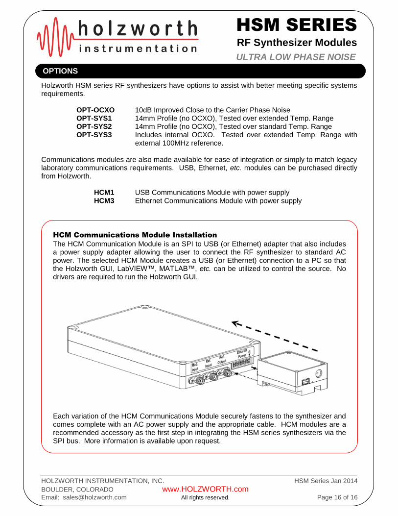
HCM Communications Module Installation
The HCM Communication Module is an SPI to USB (or Ethernet) adapter that also includes a power supply adapter allowing the user to connect the RF synthesizer to standard AC power. The selected HCM Module creates a USB (or Ethernet) connection to a PC so that the Holzworth GUI, LabVIEW™, MATLAB™, etc. can be utilized to control the source. No drivers are required to run the Holzworth GUI.
Each variation of the HCM Communications Module securely fastens to the synthesizer and comes complete with an AC power supply and the appropriate cable. HCM modules are a recommended accessory as the first step in integrating the HSM series synthesizers via the SPI bus. More information is available upon request.
OPTIONS